EP1767166B1 - System for measuring esophagus proximity - Google Patents
System for measuring esophagus proximityDownload PDFInfo
- Publication number
- EP1767166B1 EP1767166B1EP06254981AEP06254981AEP1767166B1EP 1767166 B1EP1767166 B1EP 1767166B1EP 06254981 AEP06254981 AEP 06254981AEP 06254981 AEP06254981 AEP 06254981AEP 1767166 B1EP1767166 B1EP 1767166B1
- Authority
- EP
- European Patent Office
- Prior art keywords
- catheter
- esophagus
- heart
- proximity
- signal
- Prior art date
- Legal status (The legal status is an assumption and is not a legal conclusion. Google has not performed a legal analysis and makes no representation as to the accuracy of the status listed.)
- Active
Links
- 210000003238esophagusAnatomy0.000titleclaimsabstractdescription116
- 238000000034methodMethods0.000claimsabstractdescription46
- 238000013507mappingMethods0.000claimsabstractdescription22
- 230000008569processEffects0.000claimsabstractdescription11
- 238000012545processingMethods0.000claimsabstractdescription9
- 230000000747cardiac effectEffects0.000claimsdescription27
- 210000005246left atriumAnatomy0.000claimsdescription18
- 238000012544monitoring processMethods0.000claimsdescription14
- 238000004891communicationMethods0.000claimsdescription13
- 230000000007visual effectEffects0.000claimsdescription9
- 238000013153catheter ablationMethods0.000claimsdescription3
- 238000002679ablationMethods0.000abstractdescription32
- 238000005259measurementMethods0.000abstractdescription14
- 230000006378damageEffects0.000abstractdescription8
- 239000000523sampleSubstances0.000abstractdescription6
- 230000003287optical effectEffects0.000abstractdescription3
- 230000006978adaptationEffects0.000abstract1
- 230000008054signal transmissionEffects0.000abstract1
- 210000001519tissueAnatomy0.000description16
- 210000005242cardiac chamberAnatomy0.000description14
- 230000004913activationEffects0.000description13
- 230000001746atrial effectEffects0.000description11
- UXBCHTZINZNVRG-UHFFFAOYSA-N1-n-(4-sulfamoylphenyl-ethyl)-2,4,6-trimethylpyridiniumChemical compoundCC1=CC(C)=CC(C)=[N+]1CCC1=CC=C(S(N)(=O)=O)C=C1UXBCHTZINZNVRG-UHFFFAOYSA-N0.000description8
- 230000008859changeEffects0.000description8
- WABPQHHGFIMREM-UHFFFAOYSA-Nlead(0)Chemical compound[Pb]WABPQHHGFIMREM-UHFFFAOYSA-N0.000description6
- 230000001681protective effectEffects0.000description6
- 206010003119arrhythmiaDiseases0.000description5
- 239000012530fluidSubstances0.000description5
- 210000005003heart tissueAnatomy0.000description5
- 239000000463materialSubstances0.000description5
- 238000013459approachMethods0.000description4
- 230000000694effectsEffects0.000description4
- 210000001174endocardiumAnatomy0.000description4
- 238000002594fluoroscopyMethods0.000description4
- 239000003292glueSubstances0.000description4
- 229920002635polyurethanePolymers0.000description4
- 239000004814polyurethaneSubstances0.000description4
- 206010003130Arrhythmia supraventricularDiseases0.000description3
- 206010003658Atrial FibrillationDiseases0.000description3
- 230000005355Hall effectEffects0.000description3
- 239000004642PolyimideSubstances0.000description3
- 230000002159abnormal effectEffects0.000description3
- 238000010276constructionMethods0.000description3
- 230000007423decreaseEffects0.000description3
- 238000001514detection methodMethods0.000description3
- 238000002847impedance measurementMethods0.000description3
- 210000003205muscleAnatomy0.000description3
- 239000004033plasticSubstances0.000description3
- 229920003023plasticPolymers0.000description3
- 229920001721polyimidePolymers0.000description3
- 230000033764rhythmic processEffects0.000description3
- 238000000926separation methodMethods0.000description3
- 210000001013sinoatrial nodeAnatomy0.000description3
- RYGMFSIKBFXOCR-UHFFFAOYSA-NCopperChemical group[Cu]RYGMFSIKBFXOCR-UHFFFAOYSA-N0.000description2
- 238000004026adhesive bondingMethods0.000description2
- 238000004458analytical methodMethods0.000description2
- 230000001419dependent effectEffects0.000description2
- 230000001976improved effectEffects0.000description2
- 208000015181infectious diseaseDiseases0.000description2
- 230000003902lesionEffects0.000description2
- 230000033001locomotionEffects0.000description2
- 230000000144pharmacologic effectEffects0.000description2
- 230000011218segmentationEffects0.000description2
- 230000005236sound signalEffects0.000description2
- 230000001360synchronised effectEffects0.000description2
- 230000002123temporal effectEffects0.000description2
- 230000002861ventricularEffects0.000description2
- 229910001006ConstantanInorganic materials0.000description1
- 239000004593EpoxySubstances0.000description1
- 208000006687Esophageal FistulaDiseases0.000description1
- 206010065835Oesophageal fistulaDiseases0.000description1
- 229920002614Polyether block amidePolymers0.000description1
- 208000002847Surgical WoundDiseases0.000description1
- 230000032683agingEffects0.000description1
- 230000000712assemblyEffects0.000description1
- 238000000429assemblyMethods0.000description1
- 238000010009beatingMethods0.000description1
- 210000001124body fluidAnatomy0.000description1
- 239000010839body fluidSubstances0.000description1
- 210000004375bundle of hisAnatomy0.000description1
- 210000003748coronary sinusAnatomy0.000description1
- 238000011161developmentMethods0.000description1
- 230000018109developmental processEffects0.000description1
- 230000007613environmental effectEffects0.000description1
- 230000002964excitative effectEffects0.000description1
- 210000002837heart atriumAnatomy0.000description1
- 230000001939inductive effectEffects0.000description1
- 230000007774longtermEffects0.000description1
- 239000002184metalSubstances0.000description1
- 229910052751metalInorganic materials0.000description1
- 210000004165myocardiumAnatomy0.000description1
- 230000037361pathwayEffects0.000description1
- 229920001296polysiloxanePolymers0.000description1
- 230000001902propagating effectEffects0.000description1
- 230000003252repetitive effectEffects0.000description1
- 238000010187selection methodMethods0.000description1
- 229910001220stainless steelInorganic materials0.000description1
- 239000010935stainless steelSubstances0.000description1
- 238000011477surgical interventionMethods0.000description1
- 230000003685thermal hair damageEffects0.000description1
- 230000000472traumatic effectEffects0.000description1
- 230000001960triggered effectEffects0.000description1
- 238000004148unit processMethods0.000description1
- 230000002792vascularEffects0.000description1
Images


Classifications
- A—HUMAN NECESSITIES
- A61—MEDICAL OR VETERINARY SCIENCE; HYGIENE
- A61B—DIAGNOSIS; SURGERY; IDENTIFICATION
- A61B18/00—Surgical instruments, devices or methods for transferring non-mechanical forms of energy to or from the body
- A61B18/04—Surgical instruments, devices or methods for transferring non-mechanical forms of energy to or from the body by heating
- A61B18/12—Surgical instruments, devices or methods for transferring non-mechanical forms of energy to or from the body by heating by passing a current through the tissue to be heated, e.g. high-frequency current
- A61B18/14—Probes or electrodes therefor
- A61B18/1492—Probes or electrodes therefor having a flexible, catheter-like structure, e.g. for heart ablation
- A—HUMAN NECESSITIES
- A61—MEDICAL OR VETERINARY SCIENCE; HYGIENE
- A61N—ELECTROTHERAPY; MAGNETOTHERAPY; RADIATION THERAPY; ULTRASOUND THERAPY
- A61N1/00—Electrotherapy; Circuits therefor
- A61N1/02—Details
- A61N1/04—Electrodes
- A—HUMAN NECESSITIES
- A61—MEDICAL OR VETERINARY SCIENCE; HYGIENE
- A61B—DIAGNOSIS; SURGERY; IDENTIFICATION
- A61B34/00—Computer-aided surgery; Manipulators or robots specially adapted for use in surgery
- A61B34/20—Surgical navigation systems; Devices for tracking or guiding surgical instruments, e.g. for frameless stereotaxis
- A—HUMAN NECESSITIES
- A61—MEDICAL OR VETERINARY SCIENCE; HYGIENE
- A61N—ELECTROTHERAPY; MAGNETOTHERAPY; RADIATION THERAPY; ULTRASOUND THERAPY
- A61N1/00—Electrotherapy; Circuits therefor
- A—HUMAN NECESSITIES
- A61—MEDICAL OR VETERINARY SCIENCE; HYGIENE
- A61N—ELECTROTHERAPY; MAGNETOTHERAPY; RADIATION THERAPY; ULTRASOUND THERAPY
- A61N1/00—Electrotherapy; Circuits therefor
- A61N1/02—Details
- A61N1/04—Electrodes
- A61N1/05—Electrodes for implantation or insertion into the body, e.g. heart electrode
- A61N1/0517—Esophageal electrodes
- A—HUMAN NECESSITIES
- A61—MEDICAL OR VETERINARY SCIENCE; HYGIENE
- A61B—DIAGNOSIS; SURGERY; IDENTIFICATION
- A61B18/00—Surgical instruments, devices or methods for transferring non-mechanical forms of energy to or from the body
- A61B18/04—Surgical instruments, devices or methods for transferring non-mechanical forms of energy to or from the body by heating
- A61B18/12—Surgical instruments, devices or methods for transferring non-mechanical forms of energy to or from the body by heating by passing a current through the tissue to be heated, e.g. high-frequency current
- A61B18/1206—Generators therefor
- A—HUMAN NECESSITIES
- A61—MEDICAL OR VETERINARY SCIENCE; HYGIENE
- A61B—DIAGNOSIS; SURGERY; IDENTIFICATION
- A61B18/00—Surgical instruments, devices or methods for transferring non-mechanical forms of energy to or from the body
- A61B2018/00315—Surgical instruments, devices or methods for transferring non-mechanical forms of energy to or from the body for treatment of particular body parts
- A61B2018/00345—Vascular system
- A61B2018/00351—Heart
- A—HUMAN NECESSITIES
- A61—MEDICAL OR VETERINARY SCIENCE; HYGIENE
- A61B—DIAGNOSIS; SURGERY; IDENTIFICATION
- A61B18/00—Surgical instruments, devices or methods for transferring non-mechanical forms of energy to or from the body
- A61B2018/00636—Sensing and controlling the application of energy
- A61B2018/00773—Sensed parameters
- A61B2018/00779—Power or energy
- A—HUMAN NECESSITIES
- A61—MEDICAL OR VETERINARY SCIENCE; HYGIENE
- A61B—DIAGNOSIS; SURGERY; IDENTIFICATION
- A61B18/00—Surgical instruments, devices or methods for transferring non-mechanical forms of energy to or from the body
- A61B2018/00636—Sensing and controlling the application of energy
- A61B2018/00773—Sensed parameters
- A61B2018/00839—Bioelectrical parameters, e.g. ECG, EEG
- A—HUMAN NECESSITIES
- A61—MEDICAL OR VETERINARY SCIENCE; HYGIENE
- A61B—DIAGNOSIS; SURGERY; IDENTIFICATION
- A61B18/00—Surgical instruments, devices or methods for transferring non-mechanical forms of energy to or from the body
- A61B2018/00636—Sensing and controlling the application of energy
- A61B2018/00773—Sensed parameters
- A61B2018/00869—Phase
- A—HUMAN NECESSITIES
- A61—MEDICAL OR VETERINARY SCIENCE; HYGIENE
- A61B—DIAGNOSIS; SURGERY; IDENTIFICATION
- A61B18/00—Surgical instruments, devices or methods for transferring non-mechanical forms of energy to or from the body
- A61B2018/00636—Sensing and controlling the application of energy
- A61B2018/00773—Sensed parameters
- A61B2018/00875—Resistance or impedance
- A—HUMAN NECESSITIES
- A61—MEDICAL OR VETERINARY SCIENCE; HYGIENE
- A61B—DIAGNOSIS; SURGERY; IDENTIFICATION
- A61B34/00—Computer-aided surgery; Manipulators or robots specially adapted for use in surgery
- A61B34/20—Surgical navigation systems; Devices for tracking or guiding surgical instruments, e.g. for frameless stereotaxis
- A61B2034/2046—Tracking techniques
- A61B2034/2051—Electromagnetic tracking systems
- A—HUMAN NECESSITIES
- A61—MEDICAL OR VETERINARY SCIENCE; HYGIENE
- A61B—DIAGNOSIS; SURGERY; IDENTIFICATION
- A61B90/00—Instruments, implements or accessories specially adapted for surgery or diagnosis and not covered by any of the groups A61B1/00 - A61B50/00, e.g. for luxation treatment or for protecting wound edges
- A61B90/06—Measuring instruments not otherwise provided for
- A61B2090/061—Measuring instruments not otherwise provided for for measuring dimensions, e.g. length
Definitions
- This inventionis directed to a system for measuring the proximity of the esophagus to the heart, in particular, the proximity of the esophagus to an endocardial catheter in use in the heart.
- the heartwhich is comprised of atrial, ventricular, and excitatory conduction tissue, is electrically excited to beat in a synchronous, patterned fashion.
- abnormal regions of cardiac tissuedo not follow the synchronous beating cycle associated with normally conductive tissue as in patients with normal sinus rhythm. Instead, the abnormal regions of cardiac tissue aberrantly conduct to adjacent tissue, thereby disrupting the cardiac cycle into an asynchronous cardiac rhythm.
- SAsino-atrial
- AVatrioventricular
- Bundle of Histhe cardiac muscle tissue forming the walls of the ventricular and atrial cardiac chambers.
- Cardiac arrhythmiasincluding atrial arrhythmias, may be of a multiwavelet reentrant type, characterized by multiple asynchronous loops of electrical impulses that are scattered about the atrial chamber and are often self propagating.
- cardiac arrhythmiasmay also have a focal origin, such as when an isolated region of tissue in an atrium fires autonomously in a rapid, repetitive fashion.
- pharmacological approaches intended to remedy or otherwise treat atrial arrhythmiashave been disclosed, although such pharmacological solutions are not generally believed to be entirely effective in many cases, and may in some cases result in proarrhythmia and long term inefficacy.
- pharmacological solutionsare not generally believed to be entirely effective in many cases, and may in some cases result in proarrhythmia and long term inefficacy.
- surgical approacheshave also been developed with the intention of treating atrial fibrillation.
- One particular exampleis known as the "maze procedure.”
- the maze procedureis designed to relieve atrial arrhythmia by restoring effective atrial systole and sinus node control through a prescribed pattern of incisions about the tissue wall.
- the maze procedureincluded surgical incisions in both the right and the left atrial chamber. However, more recent reports predict that the surgical maze procedure may be substantially efficacious when performed only in the left atrium.
- US-6285898discusses a method of constructing a cardiac map of a heart.
- a reference catheteris fixed in position relative to the heart and may be placed in the esophagus.
- the position of a mapping catheter relative to the reference catheteris compared to determine the position of the mapping catheter in the event that the heart exhibits overall motion within a patient's chest.
- US-A-2003/0045871relates to an ablation system with selectable current path means.
- One or more ablation electrodesare provided on a first catheter, which may be inserted into a cardiac chamber.
- One or more secondary electrodesare distributed on a second catheter, which may be located in the esophagus.
- An automatic selection proceduresends a low energy pulse signal from the ablation electrode and sensed by a selected secondary electrode. Using the sensed voltage and current a controller calculates the impedance. Once all secondary electrodes have been measured, the secondary electrode with the lowest impedance is selected. The ablation procedure may then begin.
- WO-2006/055286which forms prior art for novelty only under Article 54(3) EPC, discusses a system in which ablation catheter includes a location element and an esophageal probe also includes a location element. One of the location elements is a transmitter and the other is a receiver. The transmitter and receiver are then used to calculate the distance between location elements and determine a value for a system parameter prior to ablation beginning.
- some physicianshave used standard mapping catheters to record the pre-procedure location of the esophagus.
- a pre-procedure location determinationfails to account for the mobile nature of the esophagus.
- the esophagusgenerally does not remain stationary. Rather, the esophagus often moves back and forth thereby positioning itself in different locations relative to the heart wall. As such, the esophagus may change its location during a catheter-based endocardial procedure.
- the pre-procedure determinationfails to account for this movement. Accordingly, a need exists for a method of locating the esophagus during mapping and/or ablation procedures.
- the inventionis defined in claim 1.
- the present inventionis directed to a system for continuously monitoring proximity between a catheter in a patient's heart and his esophagus, by placing a second catheter in the patient's esophagus and monitoring the proximity between the two catheters.
- the systemcontinuously applies proximity interpretation to a measured characteristic of a proximity signal sent between the two catheters and is adapted to provide to the user of the heart catheter an audio and/or visual signal indicative of the proximity and alert when the heart catheter is too close to the esophagus.
- the systemmonitors the proximity in real time while the heart catheter is in use in the heart for cardiac ablation to minimize the risk of the heart catheter perforating or burning the esophagus.
- the systemincludes an endocardial or heart catheter positioned in a heart of the patient and an esophagus catheter positioned in the esophagus of the patient.
- a proximity signalis transmitted between the cardiac catheter and the esophagus catheter and a signal processing unit compares signals from the two catheters to determine and monitor the proximity between the two catheters.
- the cathetersare separated by a distance and the signal processing unit processes the proximity signal transmitted by one of the catheters and received by the other of the catheters to detect a characteristic of the signal for determining the distance between the catheters.
- the characteristiccan be impedance, signal amplitude or signal phase or other characteristics that change or attenuate with distance.
- the systemcontinuously monitors the distance so that changes in the distance are monitored on a real-time basis.
- a system for monitoring proximity between a cardiac catheter and an esophagus of a patientincludes a cardiac catheter equipped with a location sensor detecting location signals that are processed by a location processor to determine location of the heart catheter.
- An esophagus catheteris positioned in the esophagus of the patient at a distance from the cardiac catheter.
- a proximity signal processoris provided to process the proximity signal transmitted by one catheter and received by the other catheter to detect the distance between the catheters.
- the esophagus catheterincludes an elongated catheter body having a distal region, and at least one lumen therethrough.
- the distal regionis adapted to extend in the esophagus generally posterior the left atrium of the patient's heart, and there is at least one electrode or a plurality of electrodes mounted on the distal region adapted for electrical communication of a proximity signal with the heart catheter.
- the esophagus cathetermay also a temperature sensor and/or an electromagnetic location sensor.
- a system for measuring proximity between a cardiac catheter and an esophagus of a patientcomprising: a cardiac catheter positioned in a heart of the patient, the cardiac catheter having a location sensor detecting location signals; a first processor adapted to process the location signals to determine location of the catheter HC in the patient's heart; an esophagus catheter positioned in the esophagus of the patient and positioned a distance from the cardiac catheter; a proximity signal transmitted between the cardiac catheter and the esophagus catheter; and a second processor adapted to process the proximity signal transmitted by one of the catheters and received by the other of the catheters to measure the distance between the catheters.
- an esophagus catheterfor use in measuring proximity of a cardiac catheter in a patient's heart to the patient's esophagus, comprising: an elongated catheter body having a distal region, and at least one lumen therethrough; andat least one electrode mounted on the distal region adapted for electrical communication of a proximity signal with the cardiac catheter.
- the present inventioncan be used in a method of measuring proximity between a heart catheter positioned in a patient's heart and the patient's esophagus, by positioning an esophagus catheter in the patient's esophagus, transmitting a proximity signal between esophagus catheter and the heart catheter, and monitoring a characteristic of the proximity signal dependent on or otherwise sensitive to the distance between the catheters.
- Nonlimiting examples of suitable analysis techniques for use with the aforementioned system, device and methodinclude impedance measurement, pacing signal amplitude measurement, use of a magnetic field, use of Hall effect sensors, inductance measurement, and capacitance measurement.
- the present inventionallows a physician to continuously monitor, throughout an entire mapping and/or ablation procedure, the position of the esophagus relative to the catheter in use in the heart. This continuous, real time monitoring of the location of the esophagus accounts for the mobility of the esophagus and substantially decreases the risk of damage to the esophagus.
- the present inventionprovides an esophagus proximity measurement system S for continuously monitoring proximity between an endocardial or heart catheter in a patient's heart and his esophagus by detecting and monitoring proximity between the heart catheter and an esophagus catheter in the patient's esophagus.
- a heart catheter HCis positioned in the heart, e.g., the left atrium, and an esophagus probe catheter EC is positioned in the esophagus generally posterior of the heart catheter HC.
- the system Smonitors in real time a separation or distance between the two catheters to provide an indication of their relative position for purposes of monitoring proximity between the heart catheter and the esophagus of the patient so as to avoid the heart catheter coming too close to the esophagus and damaging the esophagus.
- An audio and/or visual signal representative of the proximity (or changes thereof)is provided to an operator while the heart catheter HC is in the patient and particularly while in use during a procedure such as mapping and/or ablation of left atrium 11 .
- the system Sincludes a location pad 22 that is placed under the patient, a communication (COM) unit 20 that processes in real time location data of the catheter HC in the patient's heart and electrophysiological data of the heart, such as Local Activation Times (LATs).
- COMcommunication
- LATsLocal Activation Times
- the system 15includes a workstation 16 (with a personal computer storing patient data and maps, a mouse and a keyboard), and a visual display 18 such as an LCD monitor to display the 3-D electroanatomical map.
- the system Salso includes an electrophysiologic (EP) junction box 30 which processes electrical activity of heart chamber muscle as detected by the catheter HC for recordation and display as electrograms on an electrophysiologic (EP) recorder 32 .
- EPelectrophysiologic
- the system Sfurther includes a signal processing unit (SPU) 34 to perform proximity interpretation by processing electrical signals that are indicative of the proximity between the two catheters. Electrical signals from both catheters HC and EC are referenced in real time to each other to determine the proximity between the catheters.
- the SPU 34has three connectors: a first connector 33 for power supply 35, a second connector 37 for the esophagus catheter EC and a third connector 39 for the heart catheter HC via a patient interface unit PIU which provides cabling connections between most if not all of the components of the system S.
- Electrode signals from the heart catheter HCare transmitted to the SPU 34 through the EP junction box 30 which splits the electrode signals between the SPU 34 and the EP Recorder 32.
- the EP junction box 30therefore receives electrode signals from both catheters HC and EC and references in real-time one or more selected characteristics of the electrode signals from the catheters that are responsive to changes in the proximity, separation or distance between the catheters HC and EC, as discussed below in further detail.
- a visual and/or audio signal representative of the proximity (or change thereof) between the catheters HC and ECis provided by an optical output 45 and/or an audio output 47.
- the operator of the heart catheter HCcan assess and be informed on a real-time basis the proximity between the heart catheter HC and the esophagus catheter EC to avoid damage to the superior wall 13 of the esophagus.
- the heart catheter HCmay be similar to an electrophysiological deflectable catheter.
- one or more of the electrodes 42 and preferably the tip electrode 40are also adapted to transmit a proximity signal that travels through a posterior wall 14 of the left atrium 11 and the superior wall 13 of the esophagus to reach the esophagus catheter EC, although it is understood by one of ordinary skill in the art that alternate embodiments may adapt the ring electrodes 42 to also sense proximity signal traveling from the esophagus EC and through the esophagus superior wall 13 and the left atrium posterior wall 14.
- a location sensor 44that is embedded within the catheter which responds to the magnetic fields generated by the location pad 22 to determine location of the heart catheter HC within the patient's heart.
- a control handle 43extends from the proximal end of the catheter body 42.
- the connector 48extends between the proximal end of the control handle 43 and the PIU 34 to transmit electrical signals to and from the heart catheter HC.
- the location pad 22 beneath the patientFor mapping a heart chamber, such as the left atrium, and creating an electroanatomical map, the location pad 22 beneath the patient generates external energy fields, for example three magnetic fields, that code a mapping space around the heart chamber with both temporal and spatial distinguishing characteristics. These fields contain information used to resolve the location and orientation of the location sensor 44 in the tip section of the heart catheter HC.
- Magnetic field signals received by the location sensor 44are transmitted through the catheter HC via lead wires to the PIU 24 via the connection 48.
- the PIU 24transmits the location signals to the COM unit 20 via connection 50 where the signals are amplified and filtered as appropriate.
- Data received from the location sensor 44is processed by the COM unit 20 to obtain location data of the tip of the catheter HC (for example, x, y and z coordinates and also pitch and roll and yaw). Accordingly, a 3-D map of the heart chamber geometry can be generated using a plurality or series of location data obtained by dragging or otherwise moving the distal tip of the heart catheter along the endocardium of the heart chamber.
- the heart chamber muscle electrical activity detected by the heart catheterare also transmitted to the COM unit 20 which serves as an electrophysiologic signal processor by calculating local activation times (LATs).
- the LATsare transmitted via connection 60 to the workstation 16 which generates a 3-D real-time electroanatomical map for viewing on the display 18.
- the map's electrophysiological informationmay be color coded and superimposed on the 3-D heart chamber geometry generated from the location mapping obtained by the location sensor of the heart catheter described hereinabove. Accordingly, an operator viewing the display is provided with a 3-D graphical representation of the patient's heart that is color coded in regions to show different LATs. For example, the color red represents shorter LATs and the color purple represents longer LATs.
- regions closest to the sinus nodeare red and regions farthest to the sinus node are purple.
- different mapsare constructed showing different activation sequences.
- the userhas access to a 3-D color-coded graphical representation of the patient's LATs.
- the system 15may also include an actuator 62, e.g., a foot pedal, in communication with the system that allows the user to accept or reject data points.
- the system 15may also include a printer 64 for printing the color-coded, 3-D graphical anatomical and/or electrophysiological representation of the heart.
- the SPU 34receives and processes signals detected by electrodes 70 on the esophagus catheter EC and the electrodes 42 on the heart catheter HC.
- the catheters and the SPU 34completes a circuit as electrical signals conduct between the two catheters by traveling through the heart tissue, the esophagus tissue and body fluids between the two catheters. Taking into consideration the known electrical properties of such tissue and fluids, the SPU 34 references the electrical signals from both catheters to each other to determine the proximity therebetween.
- an ablation energy source 90provides energy via connection 92 to the PIU 24 and the connection 48 to the catheter HC.
- the ablation energy sourcemay be RF in nature, cryogenic, ultrasonic or microwave, as understood by one of ordinary skill in the art.
- proximity interpretation performed by the SPU 34is based on impedance in the current through the catheters EC and HC, as generated by a signal generator 80 supplying a signal to, for example, the heart catheter HC.
- the signalfor example, an AC signal of 2 ⁇ Amps at 50kHz, is transmitted to the PIU 24 via connection 82 where the signal is amplified using operational amplifiers and then applied to the tip electrode 40 of the heart catheter HC via the connection 48.
- the signalflows from the tip electrode 40 of the catheter HC through the posterior wall 14 of the left atrium 11 and the superior wall 13 of the esophagus and any fluids present along this path and is sensed by the electrodes 70 on the catheter EC.
- a decrease in intercatheter impedancetriggers a visual and/or audio signal to the user via the outputs 45 and/or 47 to caution that the heart catheter distal tip is close to the esophagus.
- the audio and/or visual outputsmay, for example, be triggered when a threshold proximity has been reached.
- the activation frequency of the outputs 45 and 47may be made proportional to the intercatheter proximity.
- proximity interpretationmay also be based on a pacing signal sent by the SPU 34 to the esophagus catheter EC and transmitted by the electrodes 70 to the tip electrode 40 of the heart catheter HC. As the distance between the catheters changes, amplitude of the pacing signal increases. As understood by one of ordinary skill in the art, the activation and/or frequency of activation of the audio/visual signal to the user can be dependent on a change in the amplitude or a threshold amplitude to alert the user that the heart catheter tip is too close to the esophagus.
- the system Smay measure a temporal change in the proximity signal between the two catheter, such as monitoring the phase of the proximity signal, or use inductive sensors (more preferable for metal detection), capacitive sensors, and/or Hall Effect sensors. These sensors may be located in the tip or body of either catheter as appropriate or desired to provide the same function in monitoring on a real-time basis the proximity of the catheters to each other.
- the signal for proximity measurementmay be transmitted by either one catheter to the other catheter, as the present system detects a characteristic of the proximity signal in monitoring the distance between the two catheters, whether the characteristic is impedance, amplitude or phase.
- the heart catheter HCis introduced into the patient's body and heart through appropriate vascular access and positioned inside the heart chamber. Additional heart catheters, such as a catheter 100 positioned in the coronary sinus, may be used as a reference catheter or external reference sensors may be used in locating the position of the heart catheter HC.
- the esophagus catheter ECis also introduced into the patient's esophagus under fluoroscopy.
- the catheter HCis dragged over the endocardium, sequentially acquiring the location of its tip together with its electrogram while in stable contact with the endocardium.
- the system Sdetermines the location and orientation of the heart catheter by means of the COM unit 20 and the system 15.
- the system Sanalyses its location and presents it to the operator, thus allowing navigation without the use of fluoroscopy.
- a local activation time at each siteis determined from the intracardiac electrogram as derived from detections by the proximal ring electrodes on the catheter tip.
- the 3-D chamber geometryis reconstructed in real time by use of the set of location points sampled from the endocardium.
- the map constructedshows the activation sequence resulting from the time activation of different zones in the cardiac chamber.
- the activation mapmay be color-coded (e.g., red indicating the earliest and purple the latest activation) and is superimposed on the 3D chamber geometry.
- proximity signalsmay be sent by one catheter and received by the other catheter, with the signals being processed by the SPU 34 to provide an audio and/or visual signal to the operator on a real time basis indicating the proximity between the electrode-bearing portion of the heart catheter HC and the electrode-bearing portion of the esophagus catheter EC.
- a baseline proximity measurementmay be taken before ablation begins to represent, for example, a minimum separation or distance to be maintained between the two catheters.
- the SPU 34can be adapted to measure and store a baseline proximity measurement against which subsequent proximity measurements are compared to alert the operator when the catheters are too close to each other.
- the operatorcan monitor the distance between the two catheters on a real-time basis and is alerted when the heart catheter HC is too close to the superior wall of the esophagus and can therefore better avoid inadvertently burning the esophagus or perforating it or the wall of the left atrium.
- the present inventionalso contemplates an esophagus proximity detection system S' which can operate without mapping or navigational capabilities, where the heart and esophagus catheters can be introduced into and used in the patient entirely by fluoroscopy as appropriate.
- electrophysiologic data sensed by the electrodes 40 on an endocardial or heart catheter HCare transmitted to the PIU 24, the EP junction box 30 and then the EP recorder 32 where electrograms are stored and/or displayed.
- the ablation energy source 80is connected to the PIU 24 to energize the tip electrode 40.
- the esophagus catheter ECis connected to the SPU 34 which completes a circuit with the heart catheter HC via the EP junction box 30 and the PIU 24.
- Proximity signals generated by the signal generator 80are transmitted to the electrode 40 of the heart catheter via the connection 82, the PIU 24 and the connection 48 and are conducted through the heart wall, the esophagus wall and fluids in between, reaching the electrodes 70 of the esophagus catheter EC.
- the SPU 34processes and compares the signals from the catheters HC and EC and sends the appropriate activation signals to the optical and or audio outputs 45 and 47.
- the signals processed and compared by the SPU 34 to determine proximityare preferably those measured at the electrode locations for improved accuracy.
- Signals obtained or derived from another locationmay reflect environmental differences such as different tissues and different fluids that may alter the characteristic measured by the SPU 34.
- the heart cathetermay be similar to an electrophysiological deflectable catheter having a tip electrode and several proximal ring electrodes.
- the cathetermay be adapted for mapping and/or ablation.
- suitable ablation catheters for use as the heart catheter HC with tip electrodes and/or ablation assembliesinclude those described in US-6733499 , US-6477396 , US-6475214 and. US-6371955 .
- suitable mapping catheters for use as the heart catheter HCare described in a PCT application filed in Israel on Jan. 8, 1997, by applicant "Biosense” and titled “Mapping Catheter", the disclosure of which is incorporated herein by reference.
- a system 15 for cardiac mapping and navigationmay be a CARTO system, available from Biosense (Israel) LTD., Tirat Hacarmel, Israel, for determining the position of a catheter.
- Suitable electromagnetic sensors for use with the present inventionare described, for example, in US-5558091 , US-5443489 , US-5480422 , US-5546951 and US-5391199 .
- the illustrated embodiment of the esophagus catheter EC of FIG. 1generally comprises an elongated catheter body 112 having proximal and distal ends, and a distal region 114 that is configured to extend into the esophagus. On the distal region, there may be mounted a plurality of electrodes 70 and a distal tip electrode 71.
- the catheter body 112comprises an elongated tubular construction having a single, axial or central lumen 118.
- the catheter body 112is flexible, i.e., bendable, but substantially non-compressible along its length.
- the catheter body 112can be of any suitable construction and made of any suitable material.
- One exemplary constructioncomprises an outer wall 120 made of polyurethane or PEBAX.
- the outer wall 120may also be made of a suitable silicone containing material.
- the outer wall 120comprises an embedded braided mesh of stainless steel or the like to increase torsional stiffness of the catheter body 112 so that, when the proximal portion of the body 112 is rotated, portion of the catheter body 12 distal thereto will rotate in a corresponding manner.
- the outer diameter of the catheter body 112is not critical, but is preferably no more than about 8 french, more preferably about 7 french.
- the thickness of the outer wall 120is not critical, but is thin enough so that the central lumen 118 can accommodate one or more lead wires and any other desired wires, cables or tubes.
- the inner surface of the outer wall 120is lined with a stiffening tube 121 to provide improved torsional stability.
- the outer wall 120with an outer diameter of from about 2.29 mm (0.090 inches) to about 2.39 mm (0.094 inches) and an inner diameter of from about 1.55 mm (0.061 inches) to about 1.65 mm (0.065 inches).
- the catheter body 112i.e., that portion that can be inserted into the patient, can vary as desired.
- the lengthranges from about 110 cm to about 120 cm.
- the distal region 114 on which the electrodes 71 and 70 are mountedranges in length from about 1 cm to 8 cm, or about 2 cm to 7 cm or about 3 cm to 6 cm.
- the tip electrode 71is mounted on the distal end of the catheter body 112.
- the ring electrodes 70are preferably spaced apart from each other such that the electrodes span substantially the entire length of the distal region 114 of the catheter body 112.
- a plurality of mapping electrodesis preferred in most instances in order to ensure accurate determination of the location of the catheter EC relative to the heart catheter HC.
- the ring electrodes and/or the tip electrodemay be formed, at least in part, of a radiopaque material to aid in the alignment, under fluoroscopy, of the electrodes along the posterior wall of the left atrium.
- Each ring electrode 70 and the tip electrode 71is connected to a corresponding lead wire 150. The distal end of each lead wire 150 is attached to the corresponding electrode.
- each lead wire 150is electrically connected to the SPU 34, where the electrical signals received from the electrodes are analyzed with reference to the electrical proximity signals generated by the signal generator 80 to determine the proximity between the catheters as a means to monitor the distance between the distal tip of the heart catheter HC and the superior wall 13 of the esophagus.
- the electrodes of the esophagus cathetermay receive or transmit proximity signals, and the electrodes of the heart catheter may correspondingly transmit or receive proximity signals.
- the lead wires 150are enclosed within a protective sheath 162 to prevent contact with other components within the lumen of the catheter body 112.
- the protective sheath 162can be made of any suitable material, preferably polyimide.
- the protective sheath 162is anchored at its distal end to the proximal end of the catheter body 112 by gluing it to the side wall of the catheter body 112 with polyurethane glue or the like. As would be recognized by one of ordinary skill in the art, the protective sheath 162 can be eliminated if desired.
- One or more temperature sensorsmay be provided in the distal region 114 of the catheter body 112 to monitor the temperature of the esophageal tissue. Monitoring the temperature of the esophageal tissue allows the physician to control power delivery during ablation with the heart catheter HC in order to prevent thermal damage to the esophagus.
- thermocouplesany conventional temperature sensors, e.g. thermocouples or thermistors, may be used.
- the temperature sensorscomprise thermocouples formed by enameled wire pairs.
- One wire of each wire pairis a copper wire 153, e.g., a number 40 copper wire.
- the other wire of each wire pairis a constantan wire 154.
- the wires 153 and 154 of each wire pairare electrically isolated from each other except at their distal ends where they are twisted together, covered with a short piece of plastic tubing 155, e.g., polyimide, and covered with epoxy.
- the plastic tubings 155are anchored to the side wall of the catheter body 112 by glue or the like.
- the temperature sensorsmay be anchored anywhere along the length of the catheter body 112, such that the temperature of the esophageal tissue can be monitored.
- the wires 153 and 154extend through the central lumen 118 of the catheter body and out to a connector (not shown) connectable to a temperature monitor (not shown).
- the wires 153 and 154may be encased within a protective sheath 162, which can be made of any suitable material, preferably polyimide.
- the protective sheath 162is anchored at its distal end to the side wall of the catheter body 112 by gluing it to the side wall with polyurethane glue or the like.
- An electromagnetic sensor 174may be contained within the distal end of the esophagus catheter EC.
- the electromagnetic sensor 174is mounted to the side wall of the catheter body 112 by any suitable means, e.g., by polyurethane glue or the like.
- the electromagnetic sensor 174may be used to ensure that the distal end of the catheter EC is positioned in the esophagus at a location below the left atrium of the heart. Positioning the tip of the catheter EC generally below the left atrium ensures that the plurality of ring electrodes 70 on the distal region 114 are aligned along the posterior wall of the left atrium, and that the electrodes 70 and 71 span substantially the length of the posterior left atrial wall.
- the electromagnetic sensor 174may also be used to determine the proximity of the esophagus to the heart catheter HC, as discussed further below.
- the electromagnetic sensor 174is connected to an electromagnetic sensor cable 175, which extends through the central lumen 118 of the catheter body 112, and out through the electrical connector 37.
- the electromagnetic sensor cable 175comprises multiple wires encased within a plastic covered sheath.
- the PIU 24amplifies the signal received from the electromagnetic sensor 174 and transmits it to the COM unit 20. Because the catheter EC is designed for a single use only, the circuit board may contain and EPROM chip which shuts down the circuit board approximately 24 hours after the catheter has been used. This prevents the catheter, or at least the electromagnetic sensor from being used twice. Suitable electromagnetic sensors for use with the present invention are described, for example, in US-5558091 , US-5443489 , US-5480422 , US-5546951 and US-5391199 .
- the SPU 34analyzes the electrical signals received from the electrodes of the esophagus catheter EC and the heart catheter HC. Once analyzed, the SPU 34 generates a signal to alert the physician to the proximity of the esophagus to the distal tip region of the heart catheter HC. In one embodiment, the SPU 34 analyzes the signals through impedance measurement. Using this technique, the impedance between the electrodes on the esophagus catheter and those on the heart catheter is continuously measured. A decrease in impedance between the two catheters indicates that the electrode(s) on the heart catheter is close to the esophagus. In one embodiment, when the impedance measurement drops below a predetermined threshold value, the physician is alerted that the electrode(s) of the heart catheter is too close to the esophagus.
- pacing signal amplitude measurementis used to measure the proximity of the ablation electrode(s) to the esophagus.
- a pacing signalis sent to the electrodes on the esophagus probe catheter EC and is detected by the electrode(s) on the heart catheter HC.
- the amplitude of the pacing signalincreases, indicating that the electrode(s) of the heart catheter HC are close to the esophagus.
- the physicianis alerted that the electrode(s) of the heart catheter HC are too close to the esophagus.
- Suitable techniques for determining the proximity of the ablation electrode to the esophagusinclude inductance measurement, capacitance measurement and the use of Hall effect sensors.
Landscapes
- Health & Medical Sciences (AREA)
- Engineering & Computer Science (AREA)
- Life Sciences & Earth Sciences (AREA)
- Public Health (AREA)
- Animal Behavior & Ethology (AREA)
- Nuclear Medicine, Radiotherapy & Molecular Imaging (AREA)
- Veterinary Medicine (AREA)
- Surgery (AREA)
- General Health & Medical Sciences (AREA)
- Biomedical Technology (AREA)
- Heart & Thoracic Surgery (AREA)
- Molecular Biology (AREA)
- Medical Informatics (AREA)
- Cardiology (AREA)
- Radiology & Medical Imaging (AREA)
- Plasma & Fusion (AREA)
- Physics & Mathematics (AREA)
- Otolaryngology (AREA)
- Robotics (AREA)
- Measurement And Recording Of Electrical Phenomena And Electrical Characteristics Of The Living Body (AREA)
- Endoscopes (AREA)
Abstract
Description
- This invention is directed to a system for measuring the proximity of the esophagus to the heart, in particular, the proximity of the esophagus to an endocardial catheter in use in the heart.
- Cardiac arrhythmias, and atrial fibrillation in particular, persist as common and dangerous medical ailments, especially in the aging population. In patients with normal sinus rhythm, the heart, which is comprised of atrial, ventricular, and excitatory conduction tissue, is electrically excited to beat in a synchronous, patterned fashion. In patients with cardiac arrhythmias, abnormal regions of cardiac tissue do not follow the synchronous beating cycle associated with normally conductive tissue as in patients with normal sinus rhythm. Instead, the abnormal regions of cardiac tissue aberrantly conduct to adjacent tissue, thereby disrupting the cardiac cycle into an asynchronous cardiac rhythm. Such abnormal conduction has been previously known to occur at various regions of the heart, such as, for example, in the region of the sino-atrial (SA) node, along the conduction pathways of the atrioventricular (AV) node and the Bundle of His, or in the cardiac muscle tissue forming the walls of the ventricular and atrial cardiac chambers.
- Cardiac arrhythmias, including atrial arrhythmias, may be of a multiwavelet reentrant type, characterized by multiple asynchronous loops of electrical impulses that are scattered about the atrial chamber and are often self propagating. Alternatively, or in addition to the multiwavelet reentrant type, cardiac arrhythmias may also have a focal origin, such as when an isolated region of tissue in an atrium fires autonomously in a rapid, repetitive fashion.
- Several pharmacological approaches intended to remedy or otherwise treat atrial arrhythmias have been disclosed, although such pharmacological solutions are not generally believed to be entirely effective in many cases, and may in some cases result in proarrhythmia and long term inefficacy. Several surgical approaches have also been developed with the intention of treating atrial fibrillation. One particular example is known as the "maze procedure." In general, the maze procedure is designed to relieve atrial arrhythmia by restoring effective atrial systole and sinus node control through a prescribed pattern of incisions about the tissue wall. In the early clinical experiences reported, the maze procedure included surgical incisions in both the right and the left atrial chamber. However, more recent reports predict that the surgical maze procedure may be substantially efficacious when performed only in the left atrium.
- Success with surgical interventions through atrial segmentation, particularly with regard to the surgical Maze procedure, has inspired the development of less invasive catheter-based approaches to treat atrial fibrillation through cardiac tissue ablation. Examples of such catheter-based devices and treatment methods have generally targeted atrial segmentation with ablation catheter devices and methods adapted to form linear or curvilinear lesions in the wall tissue which defines the atrial chambers, such as those disclosed in
US-5617854 (Munsif),US-4898591 (Jang, et al.),US-5487385 (Avitall), andUS-5582609 (Swanson). The use of particular guiding sheath designs for use in ablation procedures in both the right and left atrial chambers are disclosed inUS-5427119 ,US-5497119 ,US-5564440 andUS-5575766 (Swartz et al.). In addition, various energy delivery modalities have been disclosed for forming such atrial wall lesions, and include use of microwave, laser and more commonly, radiofrequency energies to create conduction blocks along the cardiac tissue wall, as disclosed inWO-A-93/20767 US-5104393 (Isner, et al.) andUS-5,575,766 (Swartz, et al.). US-6285898 discusses a method of constructing a cardiac map of a heart. A reference catheter is fixed in position relative to the heart and may be placed in the esophagus. The position of a mapping catheter relative to the reference catheter is compared to determine the position of the mapping catheter in the event that the heart exhibits overall motion within a patient's chest.US-A-2003/0045871 relates to an ablation system with selectable current path means. One or more ablation electrodes are provided on a first catheter, which may be inserted into a cardiac chamber. One or more secondary electrodes are distributed on a second catheter, which may be located in the esophagus. An automatic selection procedure sends a low energy pulse signal from the ablation electrode and sensed by a selected secondary electrode. Using the sensed voltage and current a controller calculates the impedance. Once all secondary electrodes have been measured, the secondary electrode with the lowest impedance is selected. The ablation procedure may then begin.WO-2006/055286 , which forms prior art for novelty only under Article 54(3) EPC, discusses a system in which ablation catheter includes a location element and an esophageal probe also includes a location element. One of the location elements is a transmitter and the other is a receiver. The transmitter and receiver are then used to calculate the distance between location elements and determine a value for a system parameter prior to ablation beginning.- The success of catheter based ablation procedures has led to numerous improvements to the catheters used for the procedures. However, the traumatic nature of the ablation procedure has given rise to certain complications. One such complication is the possibility of damaging the esophagus, which lies very close to, and often touches the outer wall of the left atrium. Damage to the esophagus is sometimes caused when the esophagus touches or is close to the tissue in the left atrium that is being ablated. The heat from the ablation procedure may penetrate through the tissue of the left atrium and reach the esophagus. This damage to the esophagus is extremely dangerous, as the damaged esophagus often becomes infected. Due to this infection, an esophageal fistula, or hole in the esophagus, develops over time, causing the infection to spread to the heart wall. This damage to the esophagus carries an extremely high mortality rate.
- To avoid damage to the esophagus, a need exists for a method of locating the esophagus during catheter-based procedures within the heart, such as mapping and/or ablation. To that end, some physicians have used standard mapping catheters to record the pre-procedure location of the esophagus. However, such a pre-procedure location determination fails to account for the mobile nature of the esophagus. The esophagus generally does not remain stationary. Rather, the esophagus often moves back and forth thereby positioning itself in different locations relative to the heart wall. As such, the esophagus may change its location during a catheter-based endocardial procedure. The pre-procedure determination fails to account for this movement. Accordingly, a need exists for a method of locating the esophagus during mapping and/or ablation procedures.
- The invention is defined in
claim 1. - The present invention is directed to a system for continuously monitoring proximity between a catheter in a patient's heart and his esophagus, by placing a second catheter in the patient's esophagus and monitoring the proximity between the two catheters. The system continuously applies proximity interpretation to a measured characteristic of a proximity signal sent between the two catheters and is adapted to provide to the user of the heart catheter an audio and/or visual signal indicative of the proximity and alert when the heart catheter is too close to the esophagus. The system monitors the proximity in real time while the heart catheter is in use in the heart for cardiac ablation to minimize the risk of the heart catheter perforating or burning the esophagus.
- The system includes an endocardial or heart catheter positioned in a heart of the patient and an esophagus catheter positioned in the esophagus of the patient. A proximity signal is transmitted between the cardiac catheter and the esophagus catheter and a signal processing unit compares signals from the two catheters to determine and monitor the proximity between the two catheters. The catheters are separated by a distance and the signal processing unit processes the proximity signal transmitted by one of the catheters and received by the other of the catheters to detect a characteristic of the signal for determining the distance between the catheters. The characteristic can be impedance, signal amplitude or signal phase or other characteristics that change or attenuate with distance. The system continuously monitors the distance so that changes in the distance are monitored on a real-time basis.
- In another embodiment, a system for monitoring proximity between a cardiac catheter and an esophagus of a patient, includes a cardiac catheter equipped with a location sensor detecting location signals that are processed by a location processor to determine location of the heart catheter. An esophagus catheter is positioned in the esophagus of the patient at a distance from the cardiac catheter. A proximity signal processor is provided to process the proximity signal transmitted by one catheter and received by the other catheter to detect the distance between the catheters.
- The esophagus catheter includes an elongated catheter body having a distal region, and at least one lumen therethrough. In one embodiment, the distal region is adapted to extend in the esophagus generally posterior the left atrium of the patient's heart, and there is at least one electrode or a plurality of electrodes mounted on the distal region adapted for electrical communication of a proximity signal with the heart catheter. The esophagus catheter may also a temperature sensor and/or an electromagnetic location sensor.
- In another embodiment, there is provided a system for measuring proximity between a cardiac catheter and an esophagus of a patient, the system comprising: a cardiac catheter positioned in a heart of the patient, the cardiac catheter having a location sensor detecting location signals; a first processor adapted to process the location signals to determine location of the catheter HC in the patient's heart; an esophagus catheter positioned in the esophagus of the patient and positioned a distance from the cardiac catheter; a proximity signal transmitted between the cardiac catheter and the esophagus catheter; and a second processor adapted to process the proximity signal transmitted by one of the catheters and received by the other of the catheters to measure the distance between the catheters.
- In another embodiment, there is provided an esophagus catheter for use in measuring proximity of a cardiac catheter in a patient's heart to the patient's esophagus, comprising: an elongated catheter body having a distal region, and at least one lumen therethrough; andat least one electrode mounted on the distal region adapted for electrical communication of a proximity signal with the cardiac catheter.
- The present invention can be used in a method of measuring proximity between a heart catheter positioned in a patient's heart and the patient's esophagus, by positioning an esophagus catheter in the patient's esophagus, transmitting a proximity signal between esophagus catheter and the heart catheter, and monitoring a characteristic of the proximity signal dependent on or otherwise sensitive to the distance between the catheters.
- Nonlimiting examples of suitable analysis techniques for use with the aforementioned system, device and method include impedance measurement, pacing signal amplitude measurement, use of a magnetic field, use of Hall effect sensors, inductance measurement, and capacitance measurement. The present invention allows a physician to continuously monitor, throughout an entire mapping and/or ablation procedure, the position of the esophagus relative to the catheter in use in the heart. This continuous, real time monitoring of the location of the esophagus accounts for the mobility of the esophagus and substantially decreases the risk of damage to the esophagus.
- Embodiments of the invention will now be described by way of example with reference to the accompanying drawings, in which:
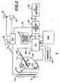
FIG. 1 is a schematic representation of a system according to one embodiment of the present invention;FIG. 2 is a schematic representation of a system according another embodiment of the present invention;FIG. 3a is a side cross-sectional view of the proximal end of the catheter body of an esophagus probe catheter according to one embodiment of the present invention;FIG. 3b is a longitudinal cross-sectional view of the proximal end of the catheter body of the esophagus catheter ofFIG. 3a , taken alongline 3b-3b;FIG. 3c is a side cross-sectional view of the distal end of the catheter body of the esophageal probe catheter ofFIG. 3 a; andFIG. 4 is a perspective view of an endocardial catheter according to one embodiment of the present invention.- Referring to
Fig. 1 , the present invention provides an esophagus proximity measurement system S for continuously monitoring proximity between an endocardial or heart catheter in a patient's heart and his esophagus by detecting and monitoring proximity between the heart catheter and an esophagus catheter in the patient's esophagus. In an embodiment of the system S, as shown inFIG.1 , a heart catheterHC is positioned in the heart, e.g., the left atrium, and an esophagus probe catheter EC is positioned in the esophagus generally posterior of the heart catheterHC. In accordance with the present invention, the system S monitors in real time a separation or distance between the two catheters to provide an indication of their relative position for purposes of monitoring proximity between the heart catheter and the esophagus of the patient so as to avoid the heart catheter coming too close to the esophagus and damaging the esophagus. An audio and/or visual signal representative of the proximity (or changes thereof) is provided to an operator while the heart catheterHC is in the patient and particularly while in use during a procedure such as mapping and/or ablation ofleft atrium 11. By monitoring the relative position of cathetersHC andEC, the operator can minimize, if not avoid, damage to superior wall13 of the esophagus such as from burn or perforation by the heart catheterHC. - In the disclosed embodiment of
FIG. 1 , the systemS includes a location pad22 that is placed under the patient, a communication (COM)unit 20 that processes in real time location data of the catheter HC in the patient's heart and electrophysiological data of the heart, such as Local Activation Times (LATs). Coupled to theCOM unit 20 is a nonfluoroscopic catheter-based electroanatomicalcardiac mapping system 15 that uses the data processed byCOM unit 20 to provide simultaneous electrophysiological and spatial information and displays a 3-D reconstruction of the mapped cardiac chamber. Thesystem 15 includes a workstation16 (with a personal computer storing patient data and maps, a mouse and a keyboard), and avisual display 18 such as an LCD monitor to display the 3-D electroanatomical map. - The systemS also includes an electrophysiologic (EP)
junction box 30 which processes electrical activity of heart chamber muscle as detected by the catheterHC for recordation and display as electrograms on an electrophysiologic (EP) recorder32. - The system S further includes a signal processing unit (SPU)34 to perform proximity interpretation by processing electrical signals that are indicative of the proximity between the two catheters. Electrical signals from both cathetersHC andEC are referenced in real time to each other to determine the proximity between the catheters. In the illustrated embodiment of
FIG. 1 , theSPU 34 has three connectors: afirst connector 33 forpower supply 35, asecond connector 37 for the esophagus catheterEC and athird connector 39 for the heart catheterHC via a patient interface unitPIU which provides cabling connections between most if not all of the components of the system S. - Electrode signals from the heart catheterHC are transmitted to the
SPU 34 through theEP junction box 30 which splits the electrode signals between theSPU 34 and the EP Recorder32. TheEP junction box 30 therefore receives electrode signals from both cathetersHC andEC and references in real-time one or more selected characteristics of the electrode signals from the catheters that are responsive to changes in the proximity, separation or distance between the cathetersHC andEC, as discussed below in further detail. In accordance with the present invention, a visual and/or audio signal representative of the proximity (or change thereof) between the cathetersHC andEC is provided by anoptical output 45 and/or anaudio output 47. As such, the operator of the heart catheterHC, particularly during ablation and mapping procedures, can assess and be informed on a real-time basis the proximity between the heart catheterHC and the esophagus catheterEC to avoid damage to the superior wall13 of the esophagus. - The heart catheterHC may be similar to an electrophysiological deflectable catheter. In one embodiment, as shown in
FIG. 4 , there is a distal portion49 that is mounted on a distal end of acatheter body 41 where the distal portion has atip electrode 40 and severalproximal ring electrodes 42 that enable recording of unipolar or bipolar signals representative of electrical activity of the heart chamber muscle, such as of theleft atrium 11. In accordance with an embodiment of the present invention, one or more of theelectrodes 42 and preferably thetip electrode 40 are also adapted to transmit a proximity signal that travels through a posterior wall14 of theleft atrium 11 and the superior wall13 of the esophagus to reach the esophagus catheterEC, although it is understood by one of ordinary skill in the art that alternate embodiments may adapt thering electrodes 42 to also sense proximity signal traveling from the esophagusEC and through the esophagus superior wall 13 and the left atrium posterior wall14. - Just proximal the tip electrode of the heart catheterHC is a location sensor44 that is embedded within the catheter which responds to the magnetic fields generated by the location pad22 to determine location of the heart catheterHC within the patient's heart.
- A control handle43 extends from the proximal end of the
catheter body 42. Theconnector 48 extends between the proximal end of the control handle43 and thePIU 34 to transmit electrical signals to and from the heart catheterHC. - For mapping a heart chamber, such as the left atrium, and creating an electroanatomical map, the location pad22 beneath the patient generates external energy fields, for example three magnetic fields, that code a mapping space around the heart chamber with both temporal and spatial distinguishing characteristics. These fields contain information used to resolve the location and orientation of the location sensor44 in the tip section of the heart catheterHC.
- Magnetic field signals received by the location sensor44 are transmitted through the catheterHC via lead wires to the
PIU 24 via theconnection 48. ThePIU 24 transmits the location signals to theCOM unit 20 via connection 50 where the signals are amplified and filtered as appropriate. Data received from the location sensor44 is processed by theCOM unit 20 to obtain location data of the tip of the catheterHC (for example, x, y and z coordinates and also pitch and roll and yaw). Accordingly, a 3-D map of the heart chamber geometry can be generated using a plurality or series of location data obtained by dragging or otherwise moving the distal tip of the heart catheter along the endocardium of the heart chamber. - Local heart electrical activity signals detected by the
ring electrodes 42 of the heart catheterHC are transmitted through the catheterHC via separate lead wires to thePIU 24 via theconnection 48. From the PIU these signals travel viaconnection 52 to theEP junction box 30 and to the EP recorder32 viaconnection 54. The EP recorder 32 records and displays the electrophysiologic data in the form of an electrocardiograph. - The heart chamber muscle electrical activity detected by the heart catheter are also transmitted to the
COM unit 20 which serves as an electrophysiologic signal processor by calculating local activation times (LATs). The LATs are transmitted via connection 60 to the workstation16 which generates a 3-D real-time electroanatomical map for viewing on thedisplay 18. The map's electrophysiological information may be color coded and superimposed on the 3-D heart chamber geometry generated from the location mapping obtained by the location sensor of the heart catheter described hereinabove. Accordingly, an operator viewing the display is provided with a 3-D graphical representation of the patient's heart that is color coded in regions to show different LATs. For example, the color red represents shorter LATs and the color purple represents longer LATs. In a normal functioning heart, regions closest to the sinus node are red and regions farthest to the sinus node are purple. Using different activation zones in the cardiac chamber, different maps are constructed showing different activation sequences. Thus, in addition to viewing the electrocardiographs provided by the EP recorder 32, the user has access to a 3-D color-coded graphical representation of the patient's LATs. - The
system 15 may also include anactuator 62, e.g., a foot pedal, in communication with the system that allows the user to accept or reject data points. Thesystem 15 may also include aprinter 64 for printing the color-coded, 3-D graphical anatomical and/or electrophysiological representation of the heart. - For proximity interpretation of the cathetersHC andEC, the
SPU 34 receives and processes signals detected byelectrodes 70 on the esophagus catheterEC and theelectrodes 42 on the heart catheterHC. The catheters and theSPU 34 completes a circuit as electrical signals conduct between the two catheters by traveling through the heart tissue, the esophagus tissue and body fluids between the two catheters. Taking into consideration the known electrical properties of such tissue and fluids, theSPU 34 references the electrical signals from both catheters to each other to determine the proximity therebetween. - Where the heart catheterHC is adapted for ablation, an
ablation energy source 90 provides energy viaconnection 92 to thePIU 24 and theconnection 48 to the catheterHC. The ablation energy source may beRF in nature, cryogenic, ultrasonic or microwave, as understood by one of ordinary skill in the art. - In one embodiment, proximity interpretation performed by the
SPU 34 is based on impedance in the current through the cathetersEC andHC, as generated by asignal generator 80 supplying a signal to, for example, the heart catheterHC. The signal, for example, an AC signal of 2µAmps at 50kHz, is transmitted to thePIU 24 viaconnection 82 where the signal is amplified using operational amplifiers and then applied to thetip electrode 40 of the heart catheterHC via theconnection 48. The signal flows from thetip electrode 40 of the catheterHC through the posterior wall14 of theleft atrium 11 and the superior wall13 of the esophagus and any fluids present along this path and is sensed by theelectrodes 70 on the catheterEC. Since the current is fixed and flows through a relatively short distance encountering generally consistent tissue and fluid media with little, if any, resistance, change in impedance in the current between the two catheters is primarily attributable to change in the distance between the catheters. Voltages at theelectrodes 70 of the esophagus catheterEC and thetip electrode 40 of the heart catheterHC are obtained and amplified by theSPU 34 which includes a microprocessor programmed to take the measured voltages and the respective fixed current outputs and apply Ohm's Law to calculate the impedance. The impedance measured (or a change in the impedance measured) can be displayed on theSPU 34 for reference by the operator. - As the cathetersHC andEC approach each other or otherwise come into close proximity of each other, a decrease in intercatheter impedance triggers a visual and/or audio signal to the user via the
outputs 45 and/or47 to caution that the heart catheter distal tip is close to the esophagus. As understood by one of ordinary skill in the art, the audio and/or visual outputs may, for example, be triggered when a threshold proximity has been reached. Or, as another example, the activation frequency of theoutputs - In another embodiment, proximity interpretation may also be based on a pacing signal sent by the
SPU 34 to the esophagus catheterEC and transmitted by theelectrodes 70 to thetip electrode 40 of the heart catheter HC. As the distance between the catheters changes, amplitude of the pacing signal increases. As understood by one of ordinary skill in the art, the activation and/or frequency of activation of the audio/visual signal to the user can be dependent on a change in the amplitude or a threshold amplitude to alert the user that the heart catheter tip is too close to the esophagus. Moreover, in alternative embodiments of the invention, the systemS may measure a temporal change in the proximity signal between the two catheter, such as monitoring the phase of the proximity signal, or use inductive sensors (more preferable for metal detection), capacitive sensors, and/or Hall Effect sensors. These sensors may be located in the tip or body of either catheter as appropriate or desired to provide the same function in monitoring on a real-time basis the proximity of the catheters to each other. - In view of the foregoing, it is further understood by one of ordinary skill in the art that the signal for proximity measurement may be transmitted by either one catheter to the other catheter, as the present system detects a characteristic of the proximity signal in monitoring the distance between the two catheters, whether the characteristic is impedance, amplitude or phase.
- Under fluoroscopic guidance, or other suitable guidance means, the heart catheterHC is introduced into the patient's body and heart through appropriate vascular access and positioned inside the heart chamber. Additional heart catheters, such as a
catheter 100 positioned in the coronary sinus, may be used as a reference catheter or external reference sensors may be used in locating the position of the heart catheterHC. The esophagus catheterEC is also introduced into the patient's esophagus under fluoroscopy. - The catheterHC is dragged over the endocardium, sequentially acquiring the location of its tip together with its electrogram while in stable contact with the endocardium. The system S determines the location and orientation of the heart catheter by means of the
COM unit 20 and thesystem 15. Thus, as the catheterHC is moved inside the heart, the system S analyses its location and presents it to the operator, thus allowing navigation without the use of fluoroscopy. - A local activation time at each site is determined from the intracardiac electrogram as derived from detections by the proximal ring electrodes on the catheter tip. The 3-D chamber geometry is reconstructed in real time by use of the set of location points sampled from the endocardium. On the basis of the various LATs, the map constructed shows the activation sequence resulting from the time activation of different zones in the cardiac chamber. The activation map may be color-coded (e.g., red indicating the earliest and purple the latest activation) and is superimposed on the 3D chamber geometry.
- As desired during mapping and/or ablation, proximity signals may be sent by one catheter and received by the other catheter, with the signals being processed by the
SPU 34 to provide an audio and/or visual signal to the operator on a real time basis indicating the proximity between the electrode-bearing portion of the heart catheterHC and the electrode-bearing portion of the esophagus catheterEC. - Where the catheter-based procedure includes ablation, a baseline proximity measurement may be taken before ablation begins to represent, for example, a minimum separation or distance to be maintained between the two catheters. To that end, the
SPU 34 can be adapted to measure and store a baseline proximity measurement against which subsequent proximity measurements are compared to alert the operator when the catheters are too close to each other. In accordance with the invention, the operator can monitor the distance between the two catheters on a real-time basis and is alerted when the heart catheterHC is too close to the superior wall of the esophagus and can therefore better avoid inadvertently burning the esophagus or perforating it or the wall of the left atrium. - The present invention also contemplates an esophagus proximity detection system S' which can operate without mapping or navigational capabilities, where the heart and esophagus catheters can be introduced into and used in the patient entirely by fluoroscopy as appropriate. As shown in
Fig. 2 , electrophysiologic data sensed by theelectrodes 40 on an endocardial or heart catheter HC are transmitted to thePIU 24, theEP junction box 30 and then the EP recorder32 where electrograms are stored and/or displayed. Where ablation is to be applied, theablation energy source 80 is connected to thePIU 24 to energize thetip electrode 40. The esophagus catheterEC is connected to theSPU 34 which completes a circuit with the heart catheterHC via theEP junction box 30 and thePIU 24. - Proximity signals generated by the
signal generator 80 are transmitted to theelectrode 40 of the heart catheter via theconnection 82, thePIU 24 and theconnection 48 and are conducted through the heart wall, the esophagus wall and fluids in between, reaching theelectrodes 70 of the esophagus catheterEC. In processes similar to those described above, theSPU 34 processes and compares the signals from the cathetersHC andEC and sends the appropriate activation signals to the optical and oraudio outputs - It is understood by one of ordinary skill in the art that for the foregoing embodiments, the signals processed and compared by the
SPU 34 to determine proximity are preferably those measured at the electrode locations for improved accuracy. Signals obtained or derived from another location (such as directly from thegenerator 80 in impedance-based proximity measurement or theSPU 34 in amplitude-based proximity measurement) may reflect environmental differences such as different tissues and different fluids that may alter the characteristic measured by theSPU 34. - For the foregoing embodiments, the heart catheter may be similar to an electrophysiological deflectable catheter having a tip electrode and several proximal ring electrodes. The catheter may be adapted for mapping and/or ablation. Nonlimiting examples of suitable ablation catheters for use as the heart catheter HC with tip electrodes and/or ablation assemblies include those described in
US-6733499 ,US-6477396 ,US-6475214 and.US-6371955 . Nonlimiting examples of suitable mapping catheters for use as the heart catheter HC are described in a PCT application filed in Israel on Jan. 8, 1997, by applicant "Biosense" and titled "Mapping Catheter", the disclosure of which is incorporated herein by reference. - Moreover, a
system 15 for cardiac mapping and navigation may be a CARTO system, available from Biosense (Israel) LTD., Tirat Hacarmel, Israel, for determining the position of a catheter. Suitable electromagnetic sensors for use with the present invention are described, for example, inUS-5558091 ,US-5443489 ,US-5480422 ,US-5546951 andUS-5391199 . - The illustrated embodiment of the esophagus catheterEC of
FIG. 1 , generally comprises anelongated catheter body 112 having proximal and distal ends, and adistal region 114 that is configured to extend into the esophagus. On the distal region, there may be mounted a plurality ofelectrodes 70 and a distal tip electrode71. - With reference to
FIG. 3 , thecatheter body 112 comprises an elongated tubular construction having a single, axial or central lumen118. Thecatheter body 112 is flexible, i.e., bendable, but substantially non-compressible along its length. Thecatheter body 112 can be of any suitable construction and made of any suitable material. One exemplary construction comprises anouter wall 120 made of polyurethane or PEBAX. Theouter wall 120 may also be made of a suitable silicone containing material. Theouter wall 120 comprises an embedded braided mesh of stainless steel or the like to increase torsional stiffness of thecatheter body 112 so that, when the proximal portion of thebody 112 is rotated, portion of thecatheter body 12 distal thereto will rotate in a corresponding manner. - The outer diameter of the
catheter body 112 is not critical, but is preferably no more than about 8 french, more preferably about 7 french. Likewise, the thickness of theouter wall 120 is not critical, but is thin enough so that the central lumen118 can accommodate one or more lead wires and any other desired wires, cables or tubes. If desired, the inner surface of theouter wall 120 is lined with astiffening tube 121 to provide improved torsional stability. In on embodiment, theouter wall 120 with an outer diameter of from about 2.29 mm (0.090 inches) to about 2.39 mm (0.094 inches) and an inner diameter of from about 1.55 mm (0.061 inches) to about 1.65 mm (0.065 inches). - The
catheter body 112, i.e., that portion that can be inserted into the patient, can vary as desired. Preferably, the length ranges from about 110 cm to about 120 cm. Thedistal region 114 on which theelectrodes 71 and70 are mounted ranges in length from about 1 cm to 8 cm, or about 2 cm to 7 cm or about 3 cm to 6 cm. - The tip electrode71 is mounted on the distal end of the
catheter body 112. Thering electrodes 70 are preferably spaced apart from each other such that the electrodes span substantially the entire length of thedistal region 114 of thecatheter body 112. A plurality of mapping electrodes is preferred in most instances in order to ensure accurate determination of the location of the catheterEC relative to the heart catheterHC. The ring electrodes and/or the tip electrode may be formed, at least in part, of a radiopaque material to aid in the alignment, under fluoroscopy, of the electrodes along the posterior wall of the left atrium.
Eachring electrode 70 and the tip electrode71 is connected to acorresponding lead wire 150. The distal end of eachlead wire 150 is attached to the corresponding electrode. The proximal end of eachlead wire 150 is electrically connected to theSPU 34, where the electrical signals received from the electrodes are analyzed with reference to the electrical proximity signals generated by thesignal generator 80 to determine the proximity between the catheters as a means to monitor the distance between the distal tip of the heart catheterHC and the superior wall13 of the esophagus. As understood by one of ordinary skill in the art, the electrodes of the esophagus catheter may receive or transmit proximity signals, and the electrodes of the heart catheter may correspondingly transmit or receive proximity signals. - As shown in
FIG. 3 , thelead wires 150 are enclosed within aprotective sheath 162 to prevent contact with other components within the lumen of thecatheter body 112. Theprotective sheath 162 can be made of any suitable material, preferably polyimide. Theprotective sheath 162 is anchored at its distal end to the proximal end of thecatheter body 112 by gluing it to the side wall of thecatheter body 112 with polyurethane glue or the like. As would be recognized by one of ordinary skill in the art, theprotective sheath 162 can be eliminated if desired. - One or more temperature sensors may be provided in the
distal region 114 of thecatheter body 112 to monitor the temperature of the esophageal tissue. Monitoring the temperature of the esophageal tissue allows the physician to control power delivery during ablation with the heart catheter HC in order to prevent thermal damage to the esophagus. - Any conventional temperature sensors, e.g. thermocouples or thermistors, may be used. In the embodiment shown in
FIGs. 3a and3c , the temperature sensors comprise thermocouples formed by enameled wire pairs. One wire of each wire pair is acopper wire 153, e.g., anumber 40 copper wire. The other wire of each wire pair is aconstantan wire 154. Thewires plastic tubing 155, e.g., polyimide, and covered with epoxy. Theplastic tubings 155 are anchored to the side wall of thecatheter body 112 by glue or the like. The temperature sensors may be anchored anywhere along the length of thecatheter body 112, such that the temperature of the esophageal tissue can be monitored. Thewires lead wires 150, thewires protective sheath 162, which can be made of any suitable material, preferably polyimide. Theprotective sheath 162 is anchored at its distal end to the side wall of thecatheter body 112 by gluing it to the side wall with polyurethane glue or the like. - An
electromagnetic sensor 174 may be contained within the distal end of the esophagus catheterEC. Theelectromagnetic sensor 174 is mounted to the side wall of thecatheter body 112 by any suitable means, e.g., by polyurethane glue or the like. Theelectromagnetic sensor 174 may be used to ensure that the distal end of the catheterEC is positioned in the esophagus at a location below the left atrium of the heart. Positioning the tip of the catheterEC generally below the left atrium ensures that the plurality ofring electrodes 70 on thedistal region 114 are aligned along the posterior wall of the left atrium, and that theelectrodes 70 and71 span substantially the length of the posterior left atrial wall. Theelectromagnetic sensor 174 may also be used to determine the proximity of the esophagus to the heart catheterHC, as discussed further below. - The
electromagnetic sensor 174 is connected to an electromagnetic sensor cable175, which extends through the central lumen118 of thecatheter body 112, and out through theelectrical connector 37. The electromagnetic sensor cable 175 comprises multiple wires encased within a plastic covered sheath. ThePIU 24 amplifies the signal received from theelectromagnetic sensor 174 and transmits it to theCOM unit 20. Because the catheterEC is designed for a single use only, the circuit board may contain and EPROM chip which shuts down the circuit board approximately 24 hours after the catheter has been used. This prevents the catheter, or at least the electromagnetic sensor from being used twice. Suitable electromagnetic sensors for use with the present invention are described, for example, inUS-5558091 ,US-5443489 ,US-5480422 ,US-5546951 andUS-5391199 . - As discussed above, the
SPU 34 analyzes the electrical signals received from the electrodes of the esophagus catheterEC and the heart catheterHC. Once analyzed, theSPU 34 generates a signal to alert the physician to the proximity of the esophagus to the distal tip region of the heart catheterHC. In one embodiment, theSPU 34 analyzes the signals through impedance measurement. Using this technique, the impedance between the electrodes on the esophagus catheter and those on the heart catheter is continuously measured. A decrease in impedance between the two catheters indicates that the electrode(s) on the heart catheter is close to the esophagus. In one embodiment, when the impedance measurement drops below a predetermined threshold value, the physician is alerted that the electrode(s) of the heart catheter is too close to the esophagus. - In an alternative embodiment, pacing signal amplitude measurement is used to measure the proximity of the ablation electrode(s) to the esophagus. Using this technique, a pacing signal is sent to the electrodes on the esophagus probe catheter EC and is detected by the electrode(s) on the heart catheter HC. As the two catheters come into proximity of each other, the amplitude of the pacing signal increases, indicating that the electrode(s) of the heart catheter HC are close to the esophagus. When the amplitude of the pacing signal rises above a threshold value, the physician is alerted that the electrode(s) of the heart catheter HC are too close to the esophagus.
- Other suitable techniques for determining the proximity of the ablation electrode to the esophagus include inductance measurement, capacitance measurement and the use of Hall effect sensors.
Claims (10)
- A system for monitoring proximity between a cardiac catheter (HC) and an esophagus of a patient, the system comprising:a cardiac catheter (HC) adapted to be positioned in a heart of the patient, the cardiac catheter comprising an electrode (40, 42);an esophagus catheter (EC) adapted to be positioned in the esophagus of the patient, the esophagus catheter comprising an electrode (70, 71);a signal processing unit (34) in electrical communication with the cardiac catheter (HC) and the esophagus catheter (EC);the signal processing unit (34) being adapted to process a proximity signal transmitted by one of the catheters (HC, EC) and received by the other of the catheters (HC, EC) to measure a characteristic of the signal for determining the distance between the electrode of the cardiac catheter and the electrode of the esophagus catheter, wherein the signal processing unit (34) is adapted to continuously process the proximity signal in real time while the cardiac catheter (HC) is in use for cardiac ablation and the signal processing unit is further adapted to generate as acoustic and/or visual alert signal when the heart cathether is too close to the esophagus while the cardiac catheter is in use for cardiac ablation.
- A system of claim 1, wherein the characteristic is impedance.
- A system of claim 1, wherein the characteristic is amplitude.
- A system of claim 1, wherein the characteristic is phase.
- A system of claim 1, wherein the signal is transmitted from the cardiac catheter (HC) to the esophagus catheter (EC).
- A system of claim 1, wherein the signal is transmitted from the esophagus catheter (EC) to the cardiac catheter (HC).
- A system of claim 1, wherein the signal is a pacing signal.
- A system of claim 1, wherein the cardiac catheter (HC) is positioned in a left atrium of the heart.
- A system of claim 1, wherein the cardiac catheter (HC) is adapted for mapping.
- A system of claim 1, wherein the esophagus catheter (EC) comprises:an elongated catheter body (112) having proximal and distal ends, and at least one lumen therethrough; and wherein the electrode of the esophagus cathether is mounted on the elongated catheter body (112).
Applications Claiming Priority (1)
| Application Number | Priority Date | Filing Date | Title |
|---|---|---|---|
| US11/236,278US8355801B2 (en) | 2005-09-26 | 2005-09-26 | System and method for measuring esophagus proximity |
Publications (2)
| Publication Number | Publication Date |
|---|---|
| EP1767166A1 EP1767166A1 (en) | 2007-03-28 |
| EP1767166B1true EP1767166B1 (en) | 2012-02-15 |
Family
ID=37635721
Family Applications (1)
| Application Number | Title | Priority Date | Filing Date |
|---|---|---|---|
| EP06254981AActiveEP1767166B1 (en) | 2005-09-26 | 2006-09-26 | System for measuring esophagus proximity |
Country Status (3)
| Country | Link |
|---|---|
| US (2) | US8355801B2 (en) |
| EP (1) | EP1767166B1 (en) |
| AT (1) | ATE545379T1 (en) |
Families Citing this family (136)
| Publication number | Priority date | Publication date | Assignee | Title |
|---|---|---|---|---|
| US10863945B2 (en)* | 2004-05-28 | 2020-12-15 | St. Jude Medical, Atrial Fibrillation Division, Inc. | Robotic surgical system with contact sensing feature |
| US8545488B2 (en) | 2004-09-17 | 2013-10-01 | The Spectranetics Corporation | Cardiovascular imaging system |
| US11478152B2 (en) | 2005-02-02 | 2022-10-25 | Intuitive Surgical Operations, Inc. | Electrophysiology mapping and visualization system |
| US8078266B2 (en) | 2005-10-25 | 2011-12-13 | Voyage Medical, Inc. | Flow reduction hood systems |
| US10064540B2 (en) | 2005-02-02 | 2018-09-04 | Intuitive Surgical Operations, Inc. | Visualization apparatus for transseptal access |
| US20080015569A1 (en) | 2005-02-02 | 2008-01-17 | Voyage Medical, Inc. | Methods and apparatus for treatment of atrial fibrillation |
| US9510732B2 (en) | 2005-10-25 | 2016-12-06 | Intuitive Surgical Operations, Inc. | Methods and apparatus for efficient purging |
| US7860555B2 (en) | 2005-02-02 | 2010-12-28 | Voyage Medical, Inc. | Tissue visualization and manipulation system |
| US8137333B2 (en) | 2005-10-25 | 2012-03-20 | Voyage Medical, Inc. | Delivery of biological compounds to ischemic and/or infarcted tissue |
| US8050746B2 (en) | 2005-02-02 | 2011-11-01 | Voyage Medical, Inc. | Tissue visualization device and method variations |
| US7860556B2 (en) | 2005-02-02 | 2010-12-28 | Voyage Medical, Inc. | Tissue imaging and extraction systems |
| US7918787B2 (en) | 2005-02-02 | 2011-04-05 | Voyage Medical, Inc. | Tissue visualization and manipulation systems |
| US7930016B1 (en) | 2005-02-02 | 2011-04-19 | Voyage Medical, Inc. | Tissue closure system |
| US20080009747A1 (en)* | 2005-02-02 | 2008-01-10 | Voyage Medical, Inc. | Transmural subsurface interrogation and ablation |
| US8221310B2 (en) | 2005-10-25 | 2012-07-17 | Voyage Medical, Inc. | Tissue visualization device and method variations |
| US10362959B2 (en)* | 2005-12-06 | 2019-07-30 | St. Jude Medical, Atrial Fibrillation Division, Inc. | System and method for assessing the proximity of an electrode to tissue in a body |
| US8403925B2 (en) | 2006-12-06 | 2013-03-26 | St. Jude Medical, Atrial Fibrillation Division, Inc. | System and method for assessing lesions in tissue |
| US8449535B2 (en)* | 2005-12-06 | 2013-05-28 | St. Jude Medical, Atrial Fibrillation Division, Inc. | System and method for assessing coupling between an electrode and tissue |
| US9254163B2 (en) | 2005-12-06 | 2016-02-09 | St. Jude Medical, Atrial Fibrillation Division, Inc. | Assessment of electrode coupling for tissue ablation |
| US8603084B2 (en) | 2005-12-06 | 2013-12-10 | St. Jude Medical, Atrial Fibrillation Division, Inc. | System and method for assessing the formation of a lesion in tissue |
| US8406866B2 (en)* | 2005-12-06 | 2013-03-26 | St. Jude Medical, Atrial Fibrillation Division, Inc. | System and method for assessing coupling between an electrode and tissue |
| US20090177111A1 (en)* | 2006-12-06 | 2009-07-09 | Miller Stephan P | System and method for displaying contact between a catheter and tissue |
| US8998890B2 (en) | 2005-12-06 | 2015-04-07 | St. Jude Medical, Atrial Fibrillation Division, Inc. | Assessment of electrode coupling for tissue ablation |
| BRPI0621017A2 (en) | 2005-12-06 | 2011-11-29 | St Jude Medical Atrial Fibrill Div | tissue ablation electrode junction evaluation |
| US9492226B2 (en)* | 2005-12-06 | 2016-11-15 | St. Jude Medical, Atrial Fibrillation Division, Inc. | Graphical user interface for real-time RF lesion depth display |
| US9055906B2 (en) | 2006-06-14 | 2015-06-16 | Intuitive Surgical Operations, Inc. | In-vivo visualization systems |
| WO2008028149A2 (en) | 2006-09-01 | 2008-03-06 | Voyage Medical, Inc. | Electrophysiology mapping and visualization system |
| US20080097476A1 (en) | 2006-09-01 | 2008-04-24 | Voyage Medical, Inc. | Precision control systems for tissue visualization and manipulation assemblies |
| US10004388B2 (en) | 2006-09-01 | 2018-06-26 | Intuitive Surgical Operations, Inc. | Coronary sinus cannulation |
| JPWO2008041755A1 (en)* | 2006-10-04 | 2010-02-04 | 東京電力株式会社 | AC / DC converter |
| RU2417732C2 (en)* | 2006-10-10 | 2011-05-10 | Байосенс Уэбстер, Инк. | Oesophageal mapping catheter |
| US10335131B2 (en)* | 2006-10-23 | 2019-07-02 | Intuitive Surgical Operations, Inc. | Methods for preventing tissue migration |
| US20080183036A1 (en) | 2006-12-18 | 2008-07-31 | Voyage Medical, Inc. | Systems and methods for unobstructed visualization and ablation |
| US8131350B2 (en) | 2006-12-21 | 2012-03-06 | Voyage Medical, Inc. | Stabilization of visualization catheters |
| US9226648B2 (en) | 2006-12-21 | 2016-01-05 | Intuitive Surgical Operations, Inc. | Off-axis visualization systems |
| US20080161890A1 (en)* | 2007-01-03 | 2008-07-03 | Boston Scientific Scimed, Inc. | Methods, systems, and apparatuses for protecting esophageal tissue during ablation |
| US10166066B2 (en)* | 2007-03-13 | 2019-01-01 | University Of Virginia Patent Foundation | Epicardial ablation catheter and method of use |
| WO2008118737A1 (en) | 2007-03-22 | 2008-10-02 | University Of Virginia Patent Foundation | Electrode catheter for ablation purposes and related method thereof |
| EP2148608A4 (en) | 2007-04-27 | 2010-04-28 | Voyage Medical Inc | Complex shape steerable tissue visualization and manipulation catheter |
| US8657805B2 (en) | 2007-05-08 | 2014-02-25 | Intuitive Surgical Operations, Inc. | Complex shape steerable tissue visualization and manipulation catheter |
| WO2008141238A1 (en) | 2007-05-11 | 2008-11-20 | Voyage Medical, Inc. | Visual electrode ablation systems |
| US8235985B2 (en) | 2007-08-31 | 2012-08-07 | Voyage Medical, Inc. | Visualization and ablation system variations |
| US8506589B2 (en)* | 2007-10-31 | 2013-08-13 | James D. Maloney | Nasogastric tube for use during an ablation procedure |
| US8529443B2 (en)* | 2007-10-31 | 2013-09-10 | James D. Maloney | Nasogastric tube for use during an ablation procedure |
| US20100241185A1 (en)* | 2007-11-09 | 2010-09-23 | University Of Virginia Patent Foundation | Steerable epicardial pacing catheter system placed via the subxiphoid process |
| US8290578B2 (en) | 2007-12-28 | 2012-10-16 | St. Jude Medical, Atrial Fibrillation Division, Inc. | Method and apparatus for complex impedance compensation |
| US9204927B2 (en) | 2009-05-13 | 2015-12-08 | St. Jude Medical, Atrial Fibrillation Division, Inc. | System and method for presenting information representative of lesion formation in tissue during an ablation procedure |
| US8858609B2 (en) | 2008-02-07 | 2014-10-14 | Intuitive Surgical Operations, Inc. | Stent delivery under direct visualization |
| WO2009143177A2 (en)* | 2008-05-19 | 2009-11-26 | Nevro Corporation | Implantable neural stimulation electrode assemblies and methods for stimulating spinal neural sites |
| US9101735B2 (en) | 2008-07-07 | 2015-08-11 | Intuitive Surgical Operations, Inc. | Catheter control systems |
| US20100049099A1 (en)* | 2008-07-18 | 2010-02-25 | Vytronus, Inc. | Method and system for positioning an energy source |
| US8333012B2 (en)* | 2008-10-10 | 2012-12-18 | Voyage Medical, Inc. | Method of forming electrode placement and connection systems |
| US8894643B2 (en) | 2008-10-10 | 2014-11-25 | Intuitive Surgical Operations, Inc. | Integral electrode placement and connection systems |
| US9403020B2 (en) | 2008-11-04 | 2016-08-02 | Nevro Corporation | Modeling positions of implanted devices in a patient |
| US9468364B2 (en) | 2008-11-14 | 2016-10-18 | Intuitive Surgical Operations, Inc. | Intravascular catheter with hood and image processing systems |
| JP5823096B2 (en)* | 2009-02-10 | 2015-11-25 | 株式会社東芝 | X-ray diagnostic apparatus and image processing method |
| US20100204561A1 (en)* | 2009-02-11 | 2010-08-12 | Voyage Medical, Inc. | Imaging catheters having irrigation |
| US9642534B2 (en) | 2009-09-11 | 2017-05-09 | University Of Virginia Patent Foundation | Systems and methods for determining location of an access needle in a subject |
| US8882759B2 (en)* | 2009-12-18 | 2014-11-11 | Covidien Lp | Microwave ablation system with dielectric temperature probe |
| US20110160832A1 (en)* | 2009-12-30 | 2011-06-30 | Amit Cohen | Electrical Metering of Active Fixation Lead Extension |
| US8694071B2 (en) | 2010-02-12 | 2014-04-08 | Intuitive Surgical Operations, Inc. | Image stabilization techniques and methods |
| US8623004B2 (en)* | 2010-03-10 | 2014-01-07 | Covidien Lp | Method for determining proximity relative to a critical structure |
| US8864761B2 (en)* | 2010-03-10 | 2014-10-21 | Covidien Lp | System and method for determining proximity relative to a critical structure |
| US8753333B2 (en)* | 2010-03-10 | 2014-06-17 | Covidien Lp | System for determining proximity relative to a nerve |
| US9814522B2 (en) | 2010-04-06 | 2017-11-14 | Intuitive Surgical Operations, Inc. | Apparatus and methods for ablation efficacy |
| US9918787B2 (en) | 2010-05-05 | 2018-03-20 | St. Jude Medical, Atrial Fibrillation Division, Inc. | Monitoring, managing and/or protecting system and method for non-targeted tissue |
| US8805519B2 (en) | 2010-09-30 | 2014-08-12 | Nevro Corporation | Systems and methods for detecting intrathecal penetration |
| US8965482B2 (en)* | 2010-09-30 | 2015-02-24 | Nevro Corporation | Systems and methods for positioning implanted devices in a patient |
| US9211094B2 (en) | 2010-12-10 | 2015-12-15 | Biosense Webster (Israel), Ltd. | System and method for detection of metal disturbance based on contact force measurement |
| US10307205B2 (en)* | 2010-12-10 | 2019-06-04 | Biosense Webster (Israel) Ltd. | System and method for detection of metal disturbance based on orthogonal field components |
| US9044244B2 (en) | 2010-12-10 | 2015-06-02 | Biosense Webster (Israel), Ltd. | System and method for detection of metal disturbance based on mutual inductance measurement |
| US9572620B2 (en)* | 2010-12-29 | 2017-02-21 | Kyungmoo Ryu | System and method for treating arrhythmias in the heart using information obtained from heart wall motion |
| US9095262B2 (en) | 2011-01-05 | 2015-08-04 | Mehdi Razavi | Guided ablation devices, systems, and methods |
| US9131853B2 (en) | 2011-07-01 | 2015-09-15 | Joseph Tiano | Medical probe and method of using same |
| US11206984B1 (en) | 2011-12-19 | 2021-12-28 | American Medical Technologies, Llc | Methods and system for cardiac mapping for atrial fibrillation using balloon based catheters utilizing medical images (CT or MRI in segments) and left ventricular lead placement for cardiac re-synchronization therapy (CRT) |
| US10413185B1 (en) | 2016-07-13 | 2019-09-17 | American Medical Technologies, Llc | Methods and system for atrial fibrillation ablation using medical images based cardiac mapping with 3-dimentional (3D) tagging with optional esophageal temperature monitoring |
| US9033968B1 (en) | 2011-12-19 | 2015-05-19 | Abl Technologies, Llc | Methods and systems of temperature based alarms, esophageal cooling and/or automatic interrupt (shut-off) during a cardic ablation procedure |
| US9393071B1 (en) | 2012-12-18 | 2016-07-19 | Abl Technologies, Llc | Methods and systems of temperature based alarms and/or automatic interrupt (shutoff) during a cardiac ablation procedure |
| US11039883B1 (en) | 2011-12-19 | 2021-06-22 | American Medical Technologies, Llc | Methods and system for atrial fibrillation ablation using balloon based catheters and utilizing medical images (CT or MRI in segments) based cardiac mapping with optional esophageal temperature monitoring |
| US9820802B1 (en) | 2015-05-11 | 2017-11-21 | American Medical Technologies, Llc | Methods and system of temperature based alarms and/or automatic interrupt (shut-off) in fluoroscopy (medical images) based mapping system for cryoballoon ablations or radiofrequency (RF) ablations for atrial fibrillation |
| AU2013211937B2 (en) | 2012-01-25 | 2016-07-28 | Nevro Corporation | Lead anchors and associated systems and methods |
| US8676331B2 (en) | 2012-04-02 | 2014-03-18 | Nevro Corporation | Devices for controlling spinal cord modulation for inhibiting pain, and associated systems and methods, including controllers for automated parameter selection |
| US9895079B2 (en)* | 2012-09-26 | 2018-02-20 | Biosense Webster (Israel) Ltd. | Electropotential mapping |
| US9623211B2 (en) | 2013-03-13 | 2017-04-18 | The Spectranetics Corporation | Catheter movement control |
| US9757200B2 (en) | 2013-03-14 | 2017-09-12 | The Spectranetics Corporation | Intelligent catheter |
| US9703317B2 (en)* | 2013-03-14 | 2017-07-11 | Biosense Webster (Israel) Ltd. | Dongle with shape memory |
| US11642169B2 (en) | 2013-03-14 | 2023-05-09 | The Spectranetics Corporation | Smart multiplexed medical laser system |
| US10758308B2 (en) | 2013-03-14 | 2020-09-01 | The Spectranetics Corporation | Controller to select optical channel parameters in a catheter |
| US9265935B2 (en) | 2013-06-28 | 2016-02-23 | Nevro Corporation | Neurological stimulation lead anchors and associated systems and methods |
| US10278775B2 (en) | 2013-12-31 | 2019-05-07 | Biosense Webster (Israel) Ltd. | Catheter utilizing optical spectroscopy for measuring tissue contact area |
| US10987168B2 (en) | 2014-05-29 | 2021-04-27 | Spectranetics Llc | System and method for coordinated laser delivery and imaging |
| US10646118B2 (en) | 2014-12-30 | 2020-05-12 | Regents Of The University Of Minnesota | Laser catheter with use of reflected light to determine material type in vascular system |
| US10646275B2 (en) | 2014-12-30 | 2020-05-12 | Regents Of The University Of Minnesota | Laser catheter with use of determined material type in vascular system in ablation of material |
| US10646274B2 (en) | 2014-12-30 | 2020-05-12 | Regents Of The University Of Minnesota | Laser catheter with use of reflected light and force indication to determine material type in vascular system |
| JP5969635B2 (en)* | 2015-01-15 | 2016-08-17 | 日本ライフライン株式会社 | catheter |
| WO2016181317A2 (en) | 2015-05-12 | 2016-11-17 | Navix International Limited | Calculation of an ablation plan |
| ITUB20155021A1 (en)* | 2015-11-03 | 2017-05-03 | Fiab S P A | Device for monitoring the optimized esophageal temperature |
| EP3422927A4 (en)* | 2016-02-29 | 2019-09-25 | The Methodist Hospital System | System and method using cardiac-esophageal impedance mapping to predict and detect esophageal injury during cardiac ablation procedures |
| US9918792B1 (en) | 2016-05-31 | 2018-03-20 | American Medical Technologies, Llc | Methods and system for atrial fibrillation ablation using a fluoroscopy and/or medical images based cardiac mapping system with optional esophageal temperature monitoring |
| US11350996B2 (en) | 2016-07-14 | 2022-06-07 | Navix International Limited | Characteristic track catheter navigation |
| US20210007673A1 (en)* | 2016-07-22 | 2021-01-14 | Northwestern University | Method and system for detecting contact between an optical probe and tissue and automating tissue measurement |
| US10042737B2 (en) | 2016-08-31 | 2018-08-07 | Microsoft Technology Licensing, Llc | Program tracing for time travel debugging and analysis |
| US10031834B2 (en) | 2016-08-31 | 2018-07-24 | Microsoft Technology Licensing, Llc | Cache-based tracing for time travel debugging and analysis |
| US10489273B2 (en) | 2016-10-20 | 2019-11-26 | Microsoft Technology Licensing, Llc | Reuse of a related thread's cache while recording a trace file of code execution |
| US10310977B2 (en) | 2016-10-20 | 2019-06-04 | Microsoft Technology Licensing, Llc | Facilitating recording a trace file of code execution using a processor cache |
| US10310963B2 (en) | 2016-10-20 | 2019-06-04 | Microsoft Technology Licensing, Llc | Facilitating recording a trace file of code execution using index bits in a processor cache |
| US10324851B2 (en) | 2016-10-20 | 2019-06-18 | Microsoft Technology Licensing, Llc | Facilitating recording a trace file of code execution using way-locking in a set-associative processor cache |
| WO2018078540A1 (en) | 2016-10-25 | 2018-05-03 | Navix International Limited | Systems and methods for registration of intra-body electrical readings with a pre-acquired three dimensional image |
| US10540250B2 (en) | 2016-11-11 | 2020-01-21 | Microsoft Technology Licensing, Llc | Reducing storage requirements for storing memory addresses and values |
| US10709507B2 (en) | 2016-11-16 | 2020-07-14 | Navix International Limited | Real-time display of treatment-related tissue changes using virtual material |
| WO2018092059A1 (en)* | 2016-11-16 | 2018-05-24 | Navix International Limited | Tissue model dynamic visual rendering |
| WO2018092071A1 (en) | 2016-11-16 | 2018-05-24 | Navix International Limited | Estimators for ablation effectiveness |
| CN110072449B (en)* | 2016-11-16 | 2023-02-24 | 纳维斯国际有限公司 | Esophageal position detection by electrical mapping |
| WO2018092062A1 (en) | 2016-11-16 | 2018-05-24 | Navix International Limited | Real-time display of tissue deformation by interactions with an intra-body probe |
| US10176630B2 (en)* | 2016-12-06 | 2019-01-08 | Biosense Webster (Israel) Ltd. | Updating an electroanatomical map |
| EP3568068A1 (en)* | 2017-01-12 | 2019-11-20 | Navix International Limited | Systems and methods for reconstruction of intra-body electrical readings to anatomical structure |
| US11471067B2 (en) | 2017-01-12 | 2022-10-18 | Navix International Limited | Intrabody probe navigation by electrical self-sensing |
| WO2018146613A2 (en)* | 2017-02-09 | 2018-08-16 | Navix International Limited | Intrabody probe navigation by electrical self-sensing |
| US11730395B2 (en) | 2017-01-12 | 2023-08-22 | Navix International Limited | Reconstruction of an anatomical structure from intrabody measurements |
| US10980999B2 (en) | 2017-03-09 | 2021-04-20 | Nevro Corp. | Paddle leads and delivery tools, and associated systems and methods |
| US10318332B2 (en) | 2017-04-01 | 2019-06-11 | Microsoft Technology Licensing, Llc | Virtual machine execution tracing |
| US10296442B2 (en) | 2017-06-29 | 2019-05-21 | Microsoft Technology Licensing, Llc | Distributed time-travel trace recording and replay |
| CN111050641B (en) | 2017-08-17 | 2023-06-09 | 纳维斯国际有限公司 | Remote imaging based on field gradients |
| US11000206B2 (en) | 2017-10-26 | 2021-05-11 | Biosense Webster (Israel) Ltd. | Esophageal probe with transmitting coils |
| US10881376B2 (en)* | 2017-11-08 | 2021-01-05 | Biosense Webster (Israel) Ltd. | System and method for providing auditory guidance in medical systems |
| US11135008B2 (en) | 2017-12-13 | 2021-10-05 | Biosense Webster (Israel) Ltd. | Graphical user interface (GUI) for displaying estimated cardiac catheter proximity to the esophagus |
| US10595938B2 (en)* | 2017-12-13 | 2020-03-24 | Biosense Webster (Israel) Ltd. | Estimating cardiac catheter proximity to the esophagus |
| EP3530315A1 (en)* | 2018-02-22 | 2019-08-28 | BIOTRONIK SE & Co. KG | A medical implant system for recapturing/explanting an implant |
| WO2019191423A1 (en) | 2018-03-29 | 2019-10-03 | Nevro Corp. | Leads having sidewall openings, and associated systems and methods |
| US11490850B2 (en)* | 2019-12-23 | 2022-11-08 | Biosense Webster (Israel) Ltd. | Handling ectopic beats in electro-anatomical mapping of the heart |
| US11711596B2 (en) | 2020-01-23 | 2023-07-25 | Covidien Lp | System and methods for determining proximity relative to an anatomical structure |
| US12094061B2 (en) | 2020-03-16 | 2024-09-17 | Covidien Lp | System and methods for updating an anatomical 3D model |
| US12233254B2 (en) | 2020-05-22 | 2025-02-25 | Avent, Inc. | System and method for muscle stimulation and/or impedance measurement to verify proper tube placement |
| US12295641B2 (en) | 2020-07-01 | 2025-05-13 | Covidien Lp | Electrosurgical forceps with swivel action nerve probe |
| WO2022093359A1 (en) | 2020-10-30 | 2022-05-05 | S4 Medical Corp | Electromagnetic sensing for use with ablation treatment |
| US12070264B2 (en) | 2021-07-23 | 2024-08-27 | Biosense Webster (Israel) Ltd. | Accurate tissue proximity |
Family Cites Families (43)
| Publication number | Priority date | Publication date | Assignee | Title |
|---|---|---|---|---|
| US4898591A (en) | 1988-08-09 | 1990-02-06 | Mallinckrodt, Inc. | Nylon-PEBA copolymer catheter |
| US4960134A (en) | 1988-11-18 | 1990-10-02 | Webster Wilton W Jr | Steerable catheter |
| US5037391A (en) | 1989-01-09 | 1991-08-06 | Pilot Cardiovascular Systems, Inc. | Steerable angioplasty device |
| US5104393A (en) | 1989-08-30 | 1992-04-14 | Angelase, Inc. | Catheter |
| US5570671A (en) | 1989-09-18 | 1996-11-05 | The Research Foundation Of State University Of New York | Method for positioning esophageal catheter for determining pressures associated with the left atrium |
| US5314466A (en) | 1992-04-13 | 1994-05-24 | Ep Technologies, Inc. | Articulated unidirectional microwave antenna systems for cardiac ablation |
| US5391199A (en) | 1993-07-20 | 1995-02-21 | Biosense, Inc. | Apparatus and method for treating cardiac arrhythmias |
| US6285898B1 (en) | 1993-07-20 | 2001-09-04 | Biosense, Inc. | Cardiac electromechanics |
| US5558091A (en) | 1993-10-06 | 1996-09-24 | Biosense, Inc. | Magnetic determination of position and orientation |
| US5582609A (en) | 1993-10-14 | 1996-12-10 | Ep Technologies, Inc. | Systems and methods for forming large lesions in body tissue using curvilinear electrode elements |
| US5575766A (en) | 1993-11-03 | 1996-11-19 | Daig Corporation | Process for the nonsurgical mapping and treatment of atrial arrhythmia using catheters guided by shaped guiding introducers |
| US5427119A (en) | 1993-11-03 | 1995-06-27 | Daig Corporation | Guiding introducer for right atrium |
| US5497774A (en) | 1993-11-03 | 1996-03-12 | Daig Corporation | Guiding introducer for left atrium |
| US5564440A (en) | 1993-11-03 | 1996-10-15 | Daig Corporation | Method for mopping and/or ablation of anomalous conduction pathways |
| US5487385A (en) | 1993-12-03 | 1996-01-30 | Avitall; Boaz | Atrial mapping and ablation catheter system |
| US5497119A (en) | 1994-06-01 | 1996-03-05 | Intel Corporation | High precision voltage regulation circuit for programming multilevel flash memory |
| US5617854A (en) | 1994-06-22 | 1997-04-08 | Munsif; Anand | Shaped catheter device and method |
| US5558665A (en) | 1994-06-24 | 1996-09-24 | Archimedes Surgical, Inc. | Surgical instrument and method for intraluminal retraction of an anatomic structure |
| NL9401107A (en) | 1994-07-01 | 1996-02-01 | Cordis Europ | Controlled bendable catheter. |
| US5681344A (en) | 1995-02-06 | 1997-10-28 | Wilson-Cook Medical Inc. | Esophageal dilation balloon catheter containing flexible nitinol wire |
| US5715832A (en) | 1995-02-28 | 1998-02-10 | Boston Scientific Corporation | Deflectable biopsy catheter |
| US6915149B2 (en)* | 1996-01-08 | 2005-07-05 | Biosense, Inc. | Method of pacing a heart using implantable device |
| US5897529A (en) | 1997-09-05 | 1999-04-27 | Cordis Webster, Inc. | Steerable deflectable catheter having improved flexibility |
| US6148222A (en) | 1998-07-10 | 2000-11-14 | Cardiocommand, Inc. | Esophageal catheters and method of use |
| US6198974B1 (en) | 1998-08-14 | 2001-03-06 | Cordis Webster, Inc. | Bi-directional steerable catheter |
| US6468260B1 (en) | 1999-05-07 | 2002-10-22 | Biosense Webster, Inc. | Single gear drive bidirectional control handle for steerable catheter |
| US6371955B1 (en) | 1999-08-10 | 2002-04-16 | Biosense Webster, Inc. | Atrial branding iron catheter and a method for treating atrial fibrillation |
| US6689062B1 (en)* | 1999-11-23 | 2004-02-10 | Microaccess Medical Systems, Inc. | Method and apparatus for transesophageal cardiovascular procedures |
| US6475214B1 (en) | 2000-05-01 | 2002-11-05 | Biosense Webster, Inc. | Catheter with enhanced ablation electrode |
| US6477396B1 (en) | 2000-07-07 | 2002-11-05 | Biosense Webster, Inc. | Mapping and ablation catheter |
| WO2002087676A2 (en)* | 2001-04-27 | 2002-11-07 | C.R. Bard, Inc. | Electrophysiology catheter for mapping and/or ablation |
| US6740080B2 (en) | 2001-08-31 | 2004-05-25 | Cardiac Pacemakers, Inc. | Ablation system with selectable current path means |
| US6895267B2 (en)* | 2001-10-24 | 2005-05-17 | Scimed Life Systems, Inc. | Systems and methods for guiding and locating functional elements on medical devices positioned in a body |
| US6733499B2 (en) | 2002-02-28 | 2004-05-11 | Biosense Webster, Inc. | Catheter having circular ablation assembly |
| US7481817B2 (en) | 2003-02-13 | 2009-01-27 | Lsi Soultions, Inc. | Instrument for surgically cutting tissue and method of use |
| US7235070B2 (en) | 2003-07-02 | 2007-06-26 | St. Jude Medical, Atrial Fibrillation Division, Inc. | Ablation fluid manifold for ablation catheter |
| US8211087B2 (en) | 2003-07-31 | 2012-07-03 | Cook Medical Technologies Llc | Distal wire stop |
| US7182761B2 (en)* | 2003-12-11 | 2007-02-27 | Scimed Life Systems, Inc. | Ablation probe with temperature sensitive electrode array |
| US20060089637A1 (en) | 2004-10-14 | 2006-04-27 | Werneth Randell L | Ablation catheter |
| US8617152B2 (en) | 2004-11-15 | 2013-12-31 | Medtronic Ablation Frontiers Llc | Ablation system with feedback |
| US20060116576A1 (en)* | 2004-12-01 | 2006-06-01 | Scimed Life Systems, Inc. | System and use thereof to provide indication of proximity between catheter and location of interest in 3-D space |
| US20060252993A1 (en) | 2005-03-23 | 2006-11-09 | Freed David I | Medical devices and systems |
| US7621908B2 (en) | 2005-11-18 | 2009-11-24 | Miller Steven W | Catheter for manipulation of the esophagus |
- 2005
- 2005-09-26USUS11/236,278patent/US8355801B2/ennot_activeExpired - Fee Related
- 2005-12-30USUS11/322,587patent/US8271095B2/ennot_activeExpired - Fee Related
- 2006
- 2006-09-26EPEP06254981Apatent/EP1767166B1/enactiveActive
- 2006-09-26ATAT06254981Tpatent/ATE545379T1/enactive
Also Published As
| Publication number | Publication date |
|---|---|
| US8271095B2 (en) | 2012-09-18 |
| US20070106287A1 (en) | 2007-05-10 |
| EP1767166A1 (en) | 2007-03-28 |
| US8355801B2 (en) | 2013-01-15 |
| ATE545379T1 (en) | 2012-03-15 |
| US20070106289A1 (en) | 2007-05-10 |
Similar Documents
| Publication | Publication Date | Title |
|---|---|---|
| EP1767166B1 (en) | System for measuring esophagus proximity | |
| EP1169973B1 (en) | Bipolar mapping of intracardiac potentials | |
| CN101766502B (en) | Dual-purpose lasso catheter with irrigation | |
| JP6209669B2 (en) | System for detecting catheter electrode entry and exit from an introducer | |
| EP2563216B1 (en) | System for performing medical procedures | |
| JP5722017B2 (en) | Mapping probe data using contact information | |
| CN102274021B (en) | Dual-purpose lasso catheter with irrigation using circumferentially arranged ring bump electrodes | |
| JP5117045B2 (en) | System and method for selectively supplying energy to a catheter electrode | |
| AU2012261575B2 (en) | Monitoring and tracking bipolar ablation | |
| CN111973272B (en) | Indicator electrode contact | |
| JP2016116858A (en) | Far field-insensitive intracardiac catheter electrodes | |
| CA2868875A1 (en) | Using catheter position and temperature measurement to detect movement from ablation point | |
| CN105030326A (en) | Prevention of steam pops during ablation | |
| CN115804606A (en) | Distal Tip Assembly Guide | |
| US12070264B2 (en) | Accurate tissue proximity | |
| US20250221649A1 (en) | Impedance based tracking of catheter location in relation to a cavity wall | |
| WO2019173288A1 (en) | Methods and systems for transmural tissue mapping | |
| US20200405385A1 (en) | Irrigation fluid monitor and alarm |
Legal Events
| Date | Code | Title | Description |
|---|---|---|---|
| PUAI | Public reference made under article 153(3) epc to a published international application that has entered the european phase | Free format text:ORIGINAL CODE: 0009012 | |
| AK | Designated contracting states | Kind code of ref document:A1 Designated state(s):AT BE BG CH CY CZ DE DK EE ES FI FR GB GR HU IE IS IT LI LT LU LV MC NL PL PT RO SE SI SK TR | |
| AX | Request for extension of the european patent | Extension state:AL BA HR MK YU | |
| 17P | Request for examination filed | Effective date:20070911 | |
| 17Q | First examination report despatched | Effective date:20071031 | |
| AKX | Designation fees paid | Designated state(s):AT BE BG CH CY CZ DE DK EE ES FI FR GB GR HU IE IS IT LI LT LU LV MC NL PL PT RO SE SI SK TR | |
| GRAP | Despatch of communication of intention to grant a patent | Free format text:ORIGINAL CODE: EPIDOSNIGR1 | |
| GRAS | Grant fee paid | Free format text:ORIGINAL CODE: EPIDOSNIGR3 | |
| GRAA | (expected) grant | Free format text:ORIGINAL CODE: 0009210 | |
| AK | Designated contracting states | Kind code of ref document:B1 Designated state(s):AT BE BG CH CY CZ DE DK EE ES FI FR GB GR HU IE IS IT LI LT LU LV MC NL PL PT RO SE SI SK TR | |
| REG | Reference to a national code | Ref country code:GB Ref legal event code:FG4D Ref country code:CH Ref legal event code:EP | |
| REG | Reference to a national code | Ref country code:IE Ref legal event code:FG4D | |
| REG | Reference to a national code | Ref country code:AT Ref legal event code:REF Ref document number:545379 Country of ref document:AT Kind code of ref document:T Effective date:20120315 | |
| REG | Reference to a national code | Ref country code:DE Ref legal event code:R096 Ref document number:602006027623 Country of ref document:DE Effective date:20120419 | |
| REG | Reference to a national code | Ref country code:NL Ref legal event code:T3 | |
| LTIE | Lt: invalidation of european patent or patent extension | Effective date:20120215 | |
| PG25 | Lapsed in a contracting state [announced via postgrant information from national office to epo] | Ref country code:LT Free format text:LAPSE BECAUSE OF FAILURE TO SUBMIT A TRANSLATION OF THE DESCRIPTION OR TO PAY THE FEE WITHIN THE PRESCRIBED TIME-LIMIT Effective date:20120215 Ref country code:IS Free format text:LAPSE BECAUSE OF FAILURE TO SUBMIT A TRANSLATION OF THE DESCRIPTION OR TO PAY THE FEE WITHIN THE PRESCRIBED TIME-LIMIT Effective date:20120615 | |
| PG25 | Lapsed in a contracting state [announced via postgrant information from national office to epo] | Ref country code:PL Free format text:LAPSE BECAUSE OF FAILURE TO SUBMIT A TRANSLATION OF THE DESCRIPTION OR TO PAY THE FEE WITHIN THE PRESCRIBED TIME-LIMIT Effective date:20120215 Ref country code:LV Free format text:LAPSE BECAUSE OF FAILURE TO SUBMIT A TRANSLATION OF THE DESCRIPTION OR TO PAY THE FEE WITHIN THE PRESCRIBED TIME-LIMIT Effective date:20120215 Ref country code:PT Free format text:LAPSE BECAUSE OF FAILURE TO SUBMIT A TRANSLATION OF THE DESCRIPTION OR TO PAY THE FEE WITHIN THE PRESCRIBED TIME-LIMIT Effective date:20120615 Ref country code:GR Free format text:LAPSE BECAUSE OF FAILURE TO SUBMIT A TRANSLATION OF THE DESCRIPTION OR TO PAY THE FEE WITHIN THE PRESCRIBED TIME-LIMIT Effective date:20120516 Ref country code:FI Free format text:LAPSE BECAUSE OF FAILURE TO SUBMIT A TRANSLATION OF THE DESCRIPTION OR TO PAY THE FEE WITHIN THE PRESCRIBED TIME-LIMIT Effective date:20120215 | |
| REG | Reference to a national code | Ref country code:AT Ref legal event code:MK05 Ref document number:545379 Country of ref document:AT Kind code of ref document:T Effective date:20120215 | |
| PG25 | Lapsed in a contracting state [announced via postgrant information from national office to epo] | Ref country code:CY Free format text:LAPSE BECAUSE OF FAILURE TO SUBMIT A TRANSLATION OF THE DESCRIPTION OR TO PAY THE FEE WITHIN THE PRESCRIBED TIME-LIMIT Effective date:20120215 | |
| PG25 | Lapsed in a contracting state [announced via postgrant information from national office to epo] | Ref country code:SI Free format text:LAPSE BECAUSE OF FAILURE TO SUBMIT A TRANSLATION OF THE DESCRIPTION OR TO PAY THE FEE WITHIN THE PRESCRIBED TIME-LIMIT Effective date:20120215 Ref country code:SE Free format text:LAPSE BECAUSE OF FAILURE TO SUBMIT A TRANSLATION OF THE DESCRIPTION OR TO PAY THE FEE WITHIN THE PRESCRIBED TIME-LIMIT Effective date:20120215 Ref country code:RO Free format text:LAPSE BECAUSE OF FAILURE TO SUBMIT A TRANSLATION OF THE DESCRIPTION OR TO PAY THE FEE WITHIN THE PRESCRIBED TIME-LIMIT Effective date:20120215 Ref country code:CZ Free format text:LAPSE BECAUSE OF FAILURE TO SUBMIT A TRANSLATION OF THE DESCRIPTION OR TO PAY THE FEE WITHIN THE PRESCRIBED TIME-LIMIT Effective date:20120215 Ref country code:DK Free format text:LAPSE BECAUSE OF FAILURE TO SUBMIT A TRANSLATION OF THE DESCRIPTION OR TO PAY THE FEE WITHIN THE PRESCRIBED TIME-LIMIT Effective date:20120215 Ref country code:EE Free format text:LAPSE BECAUSE OF FAILURE TO SUBMIT A TRANSLATION OF THE DESCRIPTION OR TO PAY THE FEE WITHIN THE PRESCRIBED TIME-LIMIT Effective date:20120215 | |
| PG25 | Lapsed in a contracting state [announced via postgrant information from national office to epo] | Ref country code:SK Free format text:LAPSE BECAUSE OF FAILURE TO SUBMIT A TRANSLATION OF THE DESCRIPTION OR TO PAY THE FEE WITHIN THE PRESCRIBED TIME-LIMIT Effective date:20120215 | |
| PLBE | No opposition filed within time limit | Free format text:ORIGINAL CODE: 0009261 | |
| STAA | Information on the status of an ep patent application or granted ep patent | Free format text:STATUS: NO OPPOSITION FILED WITHIN TIME LIMIT | |
| 26N | No opposition filed | Effective date:20121116 | |
| PG25 | Lapsed in a contracting state [announced via postgrant information from national office to epo] | Ref country code:AT Free format text:LAPSE BECAUSE OF FAILURE TO SUBMIT A TRANSLATION OF THE DESCRIPTION OR TO PAY THE FEE WITHIN THE PRESCRIBED TIME-LIMIT Effective date:20120215 | |
| REG | Reference to a national code | Ref country code:DE Ref legal event code:R097 Ref document number:602006027623 Country of ref document:DE Effective date:20121116 | |
| PG25 | Lapsed in a contracting state [announced via postgrant information from national office to epo] | Ref country code:ES Free format text:LAPSE BECAUSE OF FAILURE TO SUBMIT A TRANSLATION OF THE DESCRIPTION OR TO PAY THE FEE WITHIN THE PRESCRIBED TIME-LIMIT Effective date:20120526 Ref country code:MC Free format text:LAPSE BECAUSE OF NON-PAYMENT OF DUE FEES Effective date:20120930 | |
| REG | Reference to a national code | Ref country code:CH Ref legal event code:PL | |
| REG | Reference to a national code | Ref country code:IE Ref legal event code:MM4A | |
| PG25 | Lapsed in a contracting state [announced via postgrant information from national office to epo] | Ref country code:BG Free format text:LAPSE BECAUSE OF FAILURE TO SUBMIT A TRANSLATION OF THE DESCRIPTION OR TO PAY THE FEE WITHIN THE PRESCRIBED TIME-LIMIT Effective date:20120515 Ref country code:CH Free format text:LAPSE BECAUSE OF NON-PAYMENT OF DUE FEES Effective date:20120930 Ref country code:LI Free format text:LAPSE BECAUSE OF NON-PAYMENT OF DUE FEES Effective date:20120930 Ref country code:IE Free format text:LAPSE BECAUSE OF NON-PAYMENT OF DUE FEES Effective date:20120926 | |
| PG25 | Lapsed in a contracting state [announced via postgrant information from national office to epo] | Ref country code:TR Free format text:LAPSE BECAUSE OF FAILURE TO SUBMIT A TRANSLATION OF THE DESCRIPTION OR TO PAY THE FEE WITHIN THE PRESCRIBED TIME-LIMIT Effective date:20120215 | |
| PG25 | Lapsed in a contracting state [announced via postgrant information from national office to epo] | Ref country code:LU Free format text:LAPSE BECAUSE OF NON-PAYMENT OF DUE FEES Effective date:20120926 | |
| PG25 | Lapsed in a contracting state [announced via postgrant information from national office to epo] | Ref country code:HU Free format text:LAPSE BECAUSE OF FAILURE TO SUBMIT A TRANSLATION OF THE DESCRIPTION OR TO PAY THE FEE WITHIN THE PRESCRIBED TIME-LIMIT Effective date:20060926 | |
| REG | Reference to a national code | Ref country code:FR Ref legal event code:PLFP Year of fee payment:11 | |
| REG | Reference to a national code | Ref country code:FR Ref legal event code:PLFP Year of fee payment:12 | |
| REG | Reference to a national code | Ref country code:FR Ref legal event code:PLFP Year of fee payment:13 | |
| PGFP | Annual fee paid to national office [announced via postgrant information from national office to epo] | Ref country code:BE Payment date:20190815 Year of fee payment:14 | |
| REG | Reference to a national code | Ref country code:BE Ref legal event code:MM Effective date:20200930 | |
| PG25 | Lapsed in a contracting state [announced via postgrant information from national office to epo] | Ref country code:BE Free format text:LAPSE BECAUSE OF NON-PAYMENT OF DUE FEES Effective date:20200930 | |
| PGFP | Annual fee paid to national office [announced via postgrant information from national office to epo] | Ref country code:NL Payment date:20220819 Year of fee payment:17 | |
| REG | Reference to a national code | Ref country code:NL Ref legal event code:MM Effective date:20231001 | |
| PG25 | Lapsed in a contracting state [announced via postgrant information from national office to epo] | Ref country code:NL Free format text:LAPSE BECAUSE OF NON-PAYMENT OF DUE FEES Effective date:20231001 | |
| PG25 | Lapsed in a contracting state [announced via postgrant information from national office to epo] | Ref country code:NL Free format text:LAPSE BECAUSE OF NON-PAYMENT OF DUE FEES Effective date:20231001 | |
| PGFP | Annual fee paid to national office [announced via postgrant information from national office to epo] | Ref country code:DE Payment date:20240730 Year of fee payment:19 | |
| PGFP | Annual fee paid to national office [announced via postgrant information from national office to epo] | Ref country code:GB Payment date:20240808 Year of fee payment:19 | |
| PGFP | Annual fee paid to national office [announced via postgrant information from national office to epo] | Ref country code:FR Payment date:20240808 Year of fee payment:19 | |
| PGFP | Annual fee paid to national office [announced via postgrant information from national office to epo] | Ref country code:IT Payment date:20240812 Year of fee payment:19 |