EP1767164A1 - Electrode assembly for tissue fusion - Google Patents
Electrode assembly for tissue fusionDownload PDFInfo
- Publication number
- EP1767164A1 EP1767164A1EP05020666AEP05020666AEP1767164A1EP 1767164 A1EP1767164 A1EP 1767164A1EP 05020666 AEP05020666 AEP 05020666AEP 05020666 AEP05020666 AEP 05020666AEP 1767164 A1EP1767164 A1EP 1767164A1
- Authority
- EP
- European Patent Office
- Prior art keywords
- tissue
- engaging surfaces
- tissue engaging
- jaw members
- jaw
- Prior art date
- Legal status (The legal status is an assumption and is not a legal conclusion. Google has not performed a legal analysis and makes no representation as to the accuracy of the status listed.)
- Granted
Links
- 230000004927fusionEffects0.000titledescription4
- 238000007789sealingMethods0.000claimsabstractdescription60
- 230000004913activationEffects0.000claimsabstractdescription24
- 239000012530fluidSubstances0.000claimsabstractdescription23
- 238000000034methodMethods0.000claimsabstractdescription11
- 230000008569processEffects0.000claimsabstractdescription11
- 230000000694effectsEffects0.000claimsabstractdescription7
- 210000001519tissueAnatomy0.000description157
- 239000000463materialSubstances0.000description23
- 238000003491arrayMethods0.000description9
- PXHVJJICTQNCMI-UHFFFAOYSA-NNickelChemical compound[Ni]PXHVJJICTQNCMI-UHFFFAOYSA-N0.000description7
- 238000005345coagulationMethods0.000description4
- 230000015271coagulationEffects0.000description4
- 230000035876healingEffects0.000description4
- 229910001055inconels 600Inorganic materials0.000description4
- 239000011810insulating materialSubstances0.000description4
- 230000001105regulatory effectEffects0.000description4
- 238000011282treatmentMethods0.000description4
- -1Polybutylene TerephthalatePolymers0.000description3
- 239000000919ceramicSubstances0.000description3
- 238000000576coating methodMethods0.000description3
- 230000007797corrosionEffects0.000description3
- 238000005260corrosionMethods0.000description3
- 238000005520cutting processMethods0.000description3
- 239000012636effectorSubstances0.000description3
- 238000010438heat treatmentMethods0.000description3
- 229910052759nickelInorganic materials0.000description3
- 229920001778nylonPolymers0.000description3
- 238000002355open surgical procedureMethods0.000description3
- 230000035899viabilityEffects0.000description3
- 239000004954PolyphthalamideSubstances0.000description2
- 239000004793PolystyreneSubstances0.000description2
- 230000009471actionEffects0.000description2
- 229910045601alloyInorganic materials0.000description2
- 239000000956alloySubstances0.000description2
- 239000011248coating agentSubstances0.000description2
- 230000000295complement effectEffects0.000description2
- 238000012976endoscopic surgical procedureMethods0.000description2
- 239000012212insulatorSubstances0.000description2
- 238000012986modificationMethods0.000description2
- 230000004048modificationEffects0.000description2
- 229920001707polybutylene terephthalatePolymers0.000description2
- 229920000139polyethylene terephthalatePolymers0.000description2
- 239000005020polyethylene terephthalateSubstances0.000description2
- 229920006375polyphtalamidePolymers0.000description2
- 239000004814polyurethaneSubstances0.000description2
- 210000004872soft tissueAnatomy0.000description2
- 239000000126substanceSubstances0.000description2
- 238000001356surgical procedureMethods0.000description2
- 230000000007visual effectEffects0.000description2
- VYZAMTAEIAYCRO-UHFFFAOYSA-NChromiumChemical compound[Cr]VYZAMTAEIAYCRO-UHFFFAOYSA-N0.000description1
- 102000008186CollagenHuman genes0.000description1
- 108010035532CollagenProteins0.000description1
- 102000016942ElastinHuman genes0.000description1
- 108010014258ElastinProteins0.000description1
- 239000004677NylonSubstances0.000description1
- 229920012266Poly(ether sulfone) PESPolymers0.000description1
- 239000004721Polyphenylene oxideSubstances0.000description1
- 229910010037TiAlNInorganic materials0.000description1
- ATJFFYVFTNAWJD-UHFFFAOYSA-NTinChemical compound[Sn]ATJFFYVFTNAWJD-UHFFFAOYSA-N0.000description1
- 208000031737Tissue AdhesionsDiseases0.000description1
- DHKHKXVYLBGOIT-UHFFFAOYSA-Nacetaldehyde Diethyl AcetalNatural productsCCOC(C)OCCDHKHKXVYLBGOIT-UHFFFAOYSA-N0.000description1
- 125000002777acetyl groupChemical class[H]C([H])([H])C(*)=O0.000description1
- NIXOWILDQLNWCW-UHFFFAOYSA-Nacrylic acid groupChemical groupC(C=C)(=O)ONIXOWILDQLNWCW-UHFFFAOYSA-N0.000description1
- 229920002877acrylic styrene acrylonitrilePolymers0.000description1
- 239000004676acrylonitrile butadiene styreneSubstances0.000description1
- 125000001931aliphatic groupChemical group0.000description1
- SJKRCWUQJZIWQB-UHFFFAOYSA-Nazane;chromiumChemical compoundN.[Cr]SJKRCWUQJZIWQB-UHFFFAOYSA-N0.000description1
- 230000000740bleeding effectEffects0.000description1
- 239000008280bloodSubstances0.000description1
- 210000004369bloodAnatomy0.000description1
- 210000004204blood vesselAnatomy0.000description1
- 230000015556catabolic processEffects0.000description1
- 210000004027cellAnatomy0.000description1
- 230000008859changeEffects0.000description1
- 239000011651chromiumSubstances0.000description1
- 238000004140cleaningMethods0.000description1
- 230000001112coagulating effectEffects0.000description1
- 229920001436collagenPolymers0.000description1
- 230000000052comparative effectEffects0.000description1
- 238000010276constructionMethods0.000description1
- 230000001276controlling effectEffects0.000description1
- 229920001577copolymerPolymers0.000description1
- 230000003247decreasing effectEffects0.000description1
- 230000001419dependent effectEffects0.000description1
- 239000006185dispersionSubstances0.000description1
- 229920002549elastinPolymers0.000description1
- 239000007772electrode materialSubstances0.000description1
- 230000023597hemostasisEffects0.000description1
- 239000002874hemostatic agentSubstances0.000description1
- 229920005669high impact polystyrenePolymers0.000description1
- 239000004797high-impact polystyreneSubstances0.000description1
- 210000000936intestineAnatomy0.000description1
- 210000002429large intestineAnatomy0.000description1
- 210000004072lungAnatomy0.000description1
- 210000002751lymphAnatomy0.000description1
- 238000004519manufacturing processMethods0.000description1
- 230000007246mechanismEffects0.000description1
- 229910052751metalInorganic materials0.000description1
- 239000002184metalSubstances0.000description1
- 150000002739metalsChemical class0.000description1
- 230000017074necrotic cell deathEffects0.000description1
- CLDVQCMGOSGNIW-UHFFFAOYSA-Nnickel tinChemical compound[Ni].[Sn]CLDVQCMGOSGNIW-UHFFFAOYSA-N0.000description1
- 150000004767nitridesChemical class0.000description1
- 239000000615nonconductorSubstances0.000description1
- 235000015097nutrientsNutrition0.000description1
- 239000005416organic matterSubstances0.000description1
- 239000004033plasticSubstances0.000description1
- 229920003023plasticPolymers0.000description1
- 229920002312polyamide-imidePolymers0.000description1
- 239000004417polycarbonateSubstances0.000description1
- 229920000515polycarbonatePolymers0.000description1
- 229920001470polyketonePolymers0.000description1
- 229920000642polymerPolymers0.000description1
- 229920006380polyphenylene oxidePolymers0.000description1
- 229920002223polystyrenePolymers0.000description1
- 229920002635polyurethanePolymers0.000description1
- QMRNDFMLWNAFQR-UHFFFAOYSA-Nprop-2-enenitrile;prop-2-enoic acid;styreneChemical compoundC=CC#N.OC(=O)C=C.C=CC1=CC=CC=C1QMRNDFMLWNAFQR-UHFFFAOYSA-N0.000description1
- 238000000926separation methodMethods0.000description1
- 238000010008shearingMethods0.000description1
- 210000000813small intestineAnatomy0.000description1
- 239000010935stainless steelSubstances0.000description1
- 229910001220stainless steelInorganic materials0.000description1
- 230000001954sterilising effectEffects0.000description1
- 238000004659sterilization and disinfectionMethods0.000description1
- 229910000601superalloyInorganic materials0.000description1
- 238000009834vaporizationMethods0.000description1
- 230000008016vaporizationEffects0.000description1
- 230000002792vascularEffects0.000description1
Images


Classifications
- A—HUMAN NECESSITIES
- A61—MEDICAL OR VETERINARY SCIENCE; HYGIENE
- A61B—DIAGNOSIS; SURGERY; IDENTIFICATION
- A61B18/00—Surgical instruments, devices or methods for transferring non-mechanical forms of energy to or from the body
- A61B18/04—Surgical instruments, devices or methods for transferring non-mechanical forms of energy to or from the body by heating
- A61B18/12—Surgical instruments, devices or methods for transferring non-mechanical forms of energy to or from the body by heating by passing a current through the tissue to be heated, e.g. high-frequency current
- A61B18/14—Probes or electrodes therefor
- A61B18/1442—Probes having pivoting end effectors, e.g. forceps
- A61B18/1445—Probes having pivoting end effectors, e.g. forceps at the distal end of a shaft, e.g. forceps or scissors at the end of a rigid rod
- A—HUMAN NECESSITIES
- A61—MEDICAL OR VETERINARY SCIENCE; HYGIENE
- A61B—DIAGNOSIS; SURGERY; IDENTIFICATION
- A61B17/00—Surgical instruments, devices or methods
- A61B17/28—Surgical forceps
- A61B17/29—Forceps for use in minimally invasive surgery
- A61B2017/2926—Details of heads or jaws
- A61B2017/2945—Curved jaws
- A—HUMAN NECESSITIES
- A61—MEDICAL OR VETERINARY SCIENCE; HYGIENE
- A61B—DIAGNOSIS; SURGERY; IDENTIFICATION
- A61B18/00—Surgical instruments, devices or methods for transferring non-mechanical forms of energy to or from the body
- A61B18/04—Surgical instruments, devices or methods for transferring non-mechanical forms of energy to or from the body by heating
- A61B18/12—Surgical instruments, devices or methods for transferring non-mechanical forms of energy to or from the body by heating by passing a current through the tissue to be heated, e.g. high-frequency current
- A61B18/14—Probes or electrodes therefor
- A61B2018/1405—Electrodes having a specific shape
- A61B2018/1425—Needle
- A61B2018/1432—Needle curved
Definitions
- the present disclosurerelates to forceps used for open and/or endoscopic surgical procedures. More particularly, the present disclosure relates to a forceps which applies a unique combination of mechanical clamping pressure and electrosurgical current to micro-seal soft tissue to promote tissue healing.
- a hemostat or forcepsis a simple plier-like tool which uses mechanical action between its jaws to constrict vessels and is commonly used in open surgical procedures to grasp, dissect and/or clamp tissue.
- Electrosurgical forcepsutilize both mechanical clamping action and electrical energy to effect hemostasis by heating the tissue and blood vessels to coagulate, cauterize and/or seal tissue.
- the electrode of each opposing jaw memberis charged to a different electric potential such that when the jaw members grasp tissue, electrical energy can be selectively transferred through the tissue.
- a surgeoncan either cauterize, coagulate/desiccate and/or simply reduce or slow bleeding, by controlling the intensity, frequency and duration of the electrosurgical energy applied between the electrodes and through the tissue.
- the term "cauterization”is defined as the use of heat to destroy tissue (also called “diathermy” or “electrodiathermy”).
- the term “coagulation”is defined as a process of desiccating tissue wherein the tissue cells are ruptured and dried.
- essel sealingis defined as the process of liquefying the collagen, elastin and ground substances in the tissue so that it reforms into a fused mass with significantly-reduced demarcation between the opposing tissue structures (opposing walls of the lumen). Coagulation of small vessels is usually sufficient to permanently close them. Larger vessels or tissue need to be sealed to assure permanent closure.
- both of these parametersare affected by the thickness of the vessel or tissue being sealed. Accurate application of pressure is important for several reasons: to oppose the walls of the vessel; to reduce the tissue impedance to a low enough value that allows enough electrosurgical energy through the tissue; to overcome the forces of expansion during tissue heating; and to contribute to the end tissue thickness which is an indication of a good seal. It has been determined that a typical sealed vessel wall is optimum between 0.001 inches and 0.006 inches. Below this range, the seal may shred or tear and above this range the lumens may not be properly or effectively sealed.
- the pressure appliedbecome less relevant and the gap distance between the electrically conductive surfaces becomes more significant for effective sealing.
- the chances of the two electrically conductive surfaces touching during activationincreases as the tissue thickness and the vessels become smaller.
- tissue disposed between the two opposing jaw membersis essentially destroyed (e.g., heated, ruptured and/or dried with cauterization and coagulation and fused into a single mass with vessel sealing).
- Other known electrosurgical instrumentsinclude blade members or shearing members which simply cut tissue in a mechanical and/or electromechanical manner and, as such, also destroy tissue viability.
- the entry of fluidoften results in seal failure due to propagation of the fluid to the center of the tissue seal.
- the present disclosurerelates to a bipolar electrosurgical forceps which includes first and second opposing jaw members having respective tissue engaging surfaces associated therewith.
- the first and second jaw membersare adapted for relative movement between an open position to receive tissue and a closed position engaging tissue between the tissue engaging surfaces to effect a tissue seal upon activation of the forceps.
- the first and second jaw memberseach include an electrode having a plurality of tissue engaging surfaces which define at least one channel therebetween.
- the plurality of tissue engaging surfaces of the first jaw memberare substantially aligned with the plurality of tissue engaging surfaces of the second jaw member so as to impede fluid flow therebetween and force tissue fluid to flow within the at least one channel during the sealing process.
- the tissue engaging surfaces of the electrodesare disposed as pairs of longitudinal strips extending from a proximal end of each jaw member to a distal end thereof. At least one traversally oriented channel may be defined between respective tissue engaging surfaces on at least one jaw member.
- tissue engaging surfaces of the electrodesare disposed as series of longitudinal strips extending from a proximal end of each jaw member to a distal end thereof, with the first and second strips of the series being substantially offset relative to one another.
- tissue engaging surfaces of the electrodesare disposed as series of longitudinal strips extending from a proximal end of each jaw member to a distal end thereof, the first, second and third strips of the series being substantially offset relative to one another.
- a bipolar forceps 10is shown for use with various surgical procedures.
- Forceps 10generally includes a housing 20, a handle assembly 30, a rotating assembly 80, an activation assembly 70 and an electrode assembly 110 which mutually cooperate to grasp and seal tissue 600 (See FIGS. 5A-5C).
- an open forceps 200is also contemplated for use in connection with traditional open surgical procedures and is shown by way of example in FIG. 1B and is described below.
- either an endoscopic instrument or an open instrumentmay be utilized with the electrode assembly described herein.
- different electrical and mechanical connections and considerationsapply to each particular type of instrument, however, the novel aspects with respect to the electrode assembly and its operating characteristics remain generally consistent with respect to both the open or endoscopic designs.
- forceps 10includes a shaft 12 which has a distal end 14 dimensioned to mechanically engage a jaw assembly 110 and a proximal end 16 which mechanically engages the housing 20.
- the shaft 12may be bifurcated at the distal end 14 thereof to receive the jaw assembly 110.
- the proximal end 16 of shaft 12mechanically engages the rotating assembly 80 to facilitate rotation of the jaw assembly 110.
- proximalas is traditional, will refer to the end of the forceps 10 which is closer to the user, while the term “distal” will refer to the end which is further from the user.
- Forceps 10also includes an electrical interface or plug 300 which connects the forceps 10 to a source of electrosurgical energy, e.g., an electrosurgical generator 350 (See FIG. 3B).
- Plug 300includes a pair of prong members 302a and 302b which are dimensioned to mechanically and electrically connect the forceps 10 to the electrosurgical generator 350.
- An electrical cable 310extends from the plug 300 to a sleeve 99 which securely connects the cable 310 to the forceps 10. Cable 310 is internally divided within the housing 20 to transmit electrosurgical energy through various electrical feed paths to the jaw assembly 110 as explained in more detail below.
- Handle assembly 30includes a fixed handle 50 and a movable handle 40.
- Fixed handle 50is integrally associated with housing 20 and handle 40 is movable relative to fixed handle 50 to actuate a pair of opposing jaw members 280 and 282 of the jaw assembly 110 as explained in more detail below.
- the activation assembly 70is selectively movable by the surgeon to energize the jaw assembly 110.
- Movable handle 40 and activation assembly 70are typically of unitary construction and are operatively connected to the housing 20 and the fixed handle 50 during the assembly process.
- jaw assembly 110is attached to the distal end 14 of shaft 12 and includes a pair of opposing jaw members 280 and 282.
- Movable handle 40 of handle assembly 30imparts movement of the jaw members 280 and 282 about a pivot pin 119 from an open position wherein the jaw members 280 and 282 are disposed in spaced relation relative to one another for approximating tissue 600, to a clamping or closed position wherein the jaw members 280 and 282 cooperate to grasp tissue 600 therebetween (See FIGS. 5A-5C).
- the forceps 10may be designed such that it is fully or partially disposable depending upon a particular purpose or to achieve a particular result.
- jaw assembly 110may be selectively and releasably engageable with the distal end 14 of the shaft 12 and/or the proximal end 16 of shaft 12 may be selectively and releasably engageable with the housing 20 and the handle assembly 30.
- the forceps 10would be considered "partially disposable" or "reposable", i.e., a new or different jaw assembly 110 (or jaw assembly 110 and shaft 12) selectively replaces the old jaw assembly 110 as needed.
- an open forceps 200includes a pair of elongated shaft portions 212a each having a proximal end 216a and 216b, respectively, and a distal end 214a and 214b, respectively.
- the forceps 200includes jaw assembly 210 which attaches to distal ends 214a and 214b of shafts 212a and 212b, respectively.
- Jaw assembly 210includes opposing jaw members 280 and 282 which are pivotably connected about a pivot pin 219.
- Each shaft 212a and 212bincludes a handle 217a and 217b disposed at the proximal end 216a and 216b thereof which each define a finger hole 218a and 218b, respectively, therethrough for receiving a finger of the user.
- finger holes 218a and 218bfacilitate movement of the shafts 212a and 212b relative to one another which, in turn, pivot the jaw members 280 and 282 from an open position wherein the jaw members 280 and 282 are disposed in spaced relation relative to one another for approximating tissue 600 to a clamping or closed position wherein the jaw members 280 and 282 cooperate to grasp tissue 600 therebetween.
- a ratchet 230is included for selectively locking the jaw members 280 and 282 relative to one another at various positions during pivoting.
- Each position associated with the cooperating ratchet interfaces 230holds a specific, i.e., constant, strain energy in the shaft members 212a and 212b which, in turn, transmits a specific closing force to the jaw members 280 and 282.
- the ratchet 230may include graduations or other visual markings which enable the user to easily and quickly ascertain and control the amount of closure force desired between the jaw members 280 and 282.
- One of the shaftsincludes a proximal shaft connector /flange 221 which is designed to connect the forceps 200 to a source of electrosurgical energy such as an electrosurgical generator 350 (FIG. 3B). More particularly, flange 221 mechanically secures electrosurgical cable 310 to the forceps 200 such that the user may selectively apply electrosurgical energy as needed.
- the proximal end of the cable 310includes a similar plug 300 as described above with respect to FIG. 1A.
- the interior of cable 310houses a pair of leads which conduct different electrical potentials from the electrosurgical generator 350 to the jaw members 280 and 282 as explained below with respect to FIG. 2.
- the jaw members 280 and 282are generally symmetrical and include similar component features which cooperate to permit facile rotation about pivot 219 to effect the grasping of tissue 600.
- Each jaw member 280 and 282includes a non-conductive tissue contacting surface 284 and 286, respectively, which cooperate to engage the tissue 600 during treatment.
- the various electrical connections of the electrode assembly 210are typically configured to provide electrical continuity to an array of electrode micro-sealing pads 500 of disposed across one or both jaw members 280 and 282.
- the electrical paths 416, 426 or 516, 526 from the array of electrode micro-sealing pads 500are typically mechanically and electrically interfaced with corresponding electrical connections (not shown) disposed within shafts 212a and 212b, respectively.
- these electrical paths 416, 426 or 516, 526may be permanently soldered to the shafts 212a and 212b during the assembly process of a disposable instrument or, alternatively, selectively removable for use with a reposable instrument.
- the electrical pathsare connected to the plurality of electrode micro-sealing pads 500 within the jaw assembly 210. More particularly, the first electrical path 526 (i.e., an electrical path having a first electrical potential) is connected to each ring electrode 522 of each electrode micro-sealing pad 500. The second electrical path 516 (i.e., an electrical path having a second electrical potential) is connected to each post electrode 522 of each electrode micro-sealing pad 500.
- the electrical paths 516 and 526typically do not encumber the movement of the jaw members 280 and 282 relative to one another during the manipulation and grasping of tissue 400. Likewise, the movement of the jaw members 280 and 282 do not unnecessarily strain the electrical paths 516 and 526 or their respective connections 517, 527.
- jaw members 280 and 282both include non-conductive tissue contacting surfaces 284 and 286, respectively, disposed along substantially the entire longitudinal length thereof (i.e., extending substantially from the proximal to distal end of each respective jaw member 280 and 284).
- the non-conductive tissue contacting surfaces 284 and 286may be made from an insulative material such as ceramic due to its hardness and inherent ability to withstand high temperature fluctuations.
- the non-conductive tissue contacting surfaces 284 and 286may be made from a material or a combination of materials having a high Comparative Tracking Index (CTI) in the range of about 300 to about 600 volts.
- CTIComparative Tracking Index
- high CTI materialsinclude nylons and syndiotactic polystryrenes such as QUESTRA ® manufactured by DOW Chemical.
- Other materialsmay also be utilized either alone or in combination, e.g., Nylons, Syndiotactic-polystryrene (SPS), Polybutylene Terephthalate (PBT), Polycarbonate (PC), Acrylonitrile Butadiene Styrene (ABS), Polyphthalamide (PPA), Polymide, Polyethylene Terephthalate (PET), Polyamide-imide (PAI), Acrylic (PMMA), Polystyrene (PS and HIPS), Polyether Sulfone (PES), Aliphatic Polyketone, Acetal (POM) Copolymer, Polyurethane (PU and TPU), Nylon with Polyphenylene-oxide dispersion and Acrylonitrile Styrene Acrylate.
- the non-conductive tissue contacting surfaces 284 and 286are dimensioned to securingly engage and grasp the tissue 600 and may
- one of the jaw membersincludes at least one stop member 235a, 235b (FIG. 2) disposed on the inner facing surface of the sealing surfaces 286.
- one or more stop members 235a, 235bmay be positioned adjacent to the non-conductive sealing surfaces 284, 286 or proximate the pivot 219.
- the stop members 235a, 235bare typically designed to define a gap "G" (FIG. 5B) between opposing jaw members 280 and 282 during the micro-sealing process.
- the separation distance during micro-sealing or the gap distance "G"is within the range of about 0.001 inches (-0.03 millimeters) to about 0.006 inches (-0.016 millimeters).
- One or more stop members 235a, 235bmay be positioned on the distal end and proximal end of one or both of the jaw members 280, 282 or may be positioned between adjacent electrode micro-sealing pads 500. Moreover, the stop members 235a and 235b may be integrally associated with the non-conductive tissue contacting surfaces 284 and 286. It is envisioned that the array of electrode micro-sealing pads 500 may also act as stop members for regulating the distance "G" between opposing jaw members 280, 282 (See FIG. 4C).
- the effectiveness of the resulting micro-sealis dependent upon the pressure applied between opposing jaw members 280 and 282, the pressure applied by each electrode micro-sealing pad 500 at each micro-sealing site 620 (FIG. 4C), the gap "G" between the opposing jaw members 280 and 282 (either regaled by a stop member 235a, 235b or the array of electrode micro-sealing pads 500) and the control of the electrosurgical intensity during the micro-sealing process.
- Applying the correct forceis important to oppose the walls of the tissue; to reduce the tissue impedance to a low enough value that allows enough current through the tissue; and to overcome the forces of expansion during tissue heating in addition to contributing towards creating the required end tissue thickness which is an indication of a good micro-seal.
- Regulating the gap distance and regulating the electrosurgical intensityensure a consistent seal quality and reduce the likelihood of collateral damage to surrounding tissue.
- the electrode micro-sealing pads 500are arranged in a longitudinal, pair-like fashion along the tissue contacting surfaces 286 and/or 284. Two or more micro-sealing pads 500 may extend transversally across the tissue contacting surface 286.
- FIGS. 3A and 3Bshow one embodiment of the present disclosure wherein the electrode micro-sealing pads 500 include a ring electrode 422 disposed on one jaw members 282 and a post electrode 412 disposed on the other jaw member 280.
- the ring electrode 422includes an insulating material 424 disposed therein to form a ring electrode and insulator assembly 420 and the post electrode 422 includes an insulating material disposed therearound to form a post electrode and insulator assembly 430.
- Each post electrode assembly 430 and the ring electrode assembly 420 of this embodimenttogether define one electrode micro-sealing pad 400.
- ring electrode 422may assume any other annular or enclosed configuration or alternatively partially enclosed configuration such as a C-shape arrangement.
- the post electrode 422is concentrically centered opposite the ring electrode 422 such that when the jaw members 280 and 282 are closed about the tissue 600, electrosurgical energy flows from the ring electrode 422, through tissue 600 and to the post electrode 412.
- the insulating materials 414 and 424isolate the electrodes 412 and 422 and prevent stray current tracking to surrounding tissue.
- the electrosurgical energymay flow from the post electrode 412 to the ring electrode 422 depending upon a particular purpose.
- FIGS. 4A-4Cshow an alternate embodiment of the jaw assembly 210 according to the present disclosure for micro-sealing tissue 600 wherein each electrode micro-sealing pad 500 is disposed on a single jaw member, e.g., jaw member 280. More particularly and as best illustrated in FIG. 4B, each electrode micro-sealing pad 500 consists of an inner post electrode 512 which is surrounded by an insulative material 514, e.g., ceramic. The insulative material 514 is, in turn, encapsulated by a ring electrode 522. A second insulative material 535 (or the same insulative material 514) may be configured to encase the ring electrode 522 to prevent stray electrical currents to surrounding tissue.
- an insulative material 514e.g., ceramic
- the insulative material 514is, in turn, encapsulated by a ring electrode 522.
- a second insulative material 535(or the same insulative material 514) may be configured to encase
- the ring electrode 522is connected to the electrosurgical generator 350 by way of a cable 526 (or other conductive path) which transmits a first electrical potential to each ring electrode 522 at connection 527.
- the post electrode 512is connected to the electrosurgical generator 350 by way of a cable 516 (or other conductive path) which transmits a second electrical potential to each post electrode 522 at connection 517.
- a controller 375may be electrically interposed between the generator 350 and the electrodes 512, 522 to regulate the electrosurgical energy supplied thereto depending upon certain electrical parameters, current impedance, temperature, voltage, etc.
- the instrument or the controllermay include one or more smart sensors (not shown) which communicate with the electrosurgical generator 350 (or smart circuit, computer, feedback loop, etc.) to automatically regulate the electrosurgical intensity (waveform, current, voltage, etc.) to enhance the micro-sealing process.
- the sensormay measure or monitor one or more of the following parameters: tissue temperature, tissue impedance at the micro-seal, change in impedance of the tissue over time and/or changes in the power or current applied to the tissue over time.
- An audible or visual feedback monitor(not shown) may be employed to convey information to the surgeon regarding the overall micro-seal quality or the completion of an effective tissue micro-seal.
- a PCB circuit of flex circuitmay be utilized to provide information relating to the gap distance (e.g., a proximity detector may be employed) between the two jaw members 280 and 282, the micro-sealing pressure between the jaw members 280 and 282 prior to and during activation, load (e.g., strain gauge may be employed), the tissue thickness prior to or during activation, the impedance across the tissue during activation, the temperature during activation, the rate of tissue expansion during activation and micro-sealing. It is envisioned that the PCB circuit may be designed to provide electrical feedback to the generator 350 rotating to one or more of the above parameters either on a continuous basis or upon inquiry from the generator 350.
- loade.g., strain gauge may be employed
- a PCB circuitmay be employed to control the power, current and/or type of current waveform from the generator 350 to the jaw members 280, 282 to reduce collateral damage to surrounding tissue during activation, e.g., thermal spread, tissue vaporization and/or steam from the treatment site.
- Examples of a various control circuits, generators and algorithms which may be utilizedare disclosed in U.S. Patent No 6,228,080 and U.S. Application Serial No. 10/073,761 the entire contents of both of which are hereby incorporated by reference herein.
- the surgeoninitially approximates the tissue (FIG. 5A) between the opposing jaw member 280 and 282 and then grasps the tissue 600 (FIG. 5B) by actuating the jaw members 280, 282 to rotate about pivot 219.
- the surgeonselectively activates the generator 350 to supply electrosurgical energy to the array of the electrode micro-sealing pads 500. More particularly, electrosurgical energy flows from the ring electrode 522, through the tissue 600 and to the post electrode 512 (See FIGS. 4B and 4C). As a result thereof, an intermittent pattern of individual micro-seals 630 is created along and across the tissue 600 (See FIG. 5C).
- the arrangement of the micro-sealing pads 500 across the tissueonly seals the tissue which is between each micro-sealing pad 500 and the opposing jaw member 282.
- the adjacent tissueremains viable which, as can be appreciated, allows blood and nutrients to flow through the sealing site 620 and between the individual micro-seals 630 to promote tissue healing and reduce the chances of tissue necrosis.
- By selectively regulating the closure pressure "F”, gap distance "G”, and electrosurgical intensity, effective and consistent micro-seals 630may be created for many different tissue types.
- selective ring electrodes and post electrodesmay have varying electric potentials upon activation.
- one or a series of electrodesmay be electrically connected to a first potential and the corresponding electrodes (either on the same jaw or perhaps the opposing jaw) may be connected to a second potential.
- the corresponding electrodesmay be connected to a third potential and the corresponding electrodes connected to yet a fourth potential.
- thiswould allow different types of tissue sealing to take place at different portions of the jaw members upon activation.
- the type of sealingcould be based upon the type of tissues involved or perhaps the thickness of the tissue.
- the userwould grasp the tissue more towards the proximal portion of the opposing jaw members and to seal smaller tissue, the user would grasp the tissue more towards the distal portion of the jaw members.
- the pattern and/or density of the micro-sealing padsmay be configured to seal different types of tissue or thicknesses of tissue along the same jaw members depending upon where the tissue is grasped between opposing jaw members.
- the forceps 100, 200is less likely to become damaged since it is only intended for a single use and, therefore, does not require cleaning or sterilization.
- the functionality and consistency of the vital micro-sealing componentse.g., the conductive micro-sealing electrode pads 500, the stop member(s) 235a, 235b, and the insulative materials 514, 535 will assure a uniform and quality seal.
- Tissue pressures within a working range of about 3 kg/cm 2 to about 16 kg/cm 2 and, more particularly, within a working range of 7 kg/cm 2 to 13 kg/cm 2have been shown to be effective for micro-sealing various tissue types and vascular bundles.
- the shafts 212a and 212bare manufactured such that the spring constant of the shafts 212a and 212b, in conjunction with the placement of the interfacing surfaces of the ratchet 230, will yield pressures within the above working range.
- the successive positions of the ratchet interfacesincrease the pressure between opposing micro-sealing surfaces incrementally within the above working range.
- the outer surface of the jaw members 280 and 282may include a nickel-based material or coating which is designed to reduce adhesion between the jaw members 280, 282 (or components thereof) with the surrounding tissue during activation and micro-sealing.
- other componentssuch as the shaft portions 212a, 212b and the rings 217a, 217b may also be coated with the same or a different "non-stick" material.
- the non-stick materialsare of a class of materials that provide a smooth surface to prevent mechanical tooth adhesions.
- the tissue contacting portions of the electrodes and other portions of the micro-sealing pads 400, 500may also be made from or coated with non-stick materials.
- the non-stick materialsprovide an optimal surface energy for eliminating sticking due in part to surface texture and susceptibility to surface breakdown due electrical effects and corrosion in the presence of biologic tissues. It is envisioned that these materials exhibit superior non-stick qualities over stainless steel and should be utilized in areas where the exposure to pressure and electrosurgical energy can create localized "hot spots" more susceptible to tissue adhesion. As can be appreciated, reducing the amount that the tissue "sticks" during micro-sealing improves the overall efficacy of the instrument.
- the non-stick materialsmay be manufactured from one (or a combination of one or more) of the following “non-stick” materials: nickelchrome, chromium nitride, MedCoat 2000 manufactured by The Electrolizing Corporation of OHIO, Inconel 600 and tin-nickel.
- Inconel 600 coatingis a so-called "super alloy” which is manufactured by Special Metals, Inc. located in Conroe Texas. The alloy is primarily used in environments which require resistance to corrosion and heat.
- the high Nickel content of Inconel 600makes the material especially resistant to organic corrosion. As can be appreciated, these properties are desirable for bipolar electrosurgical instruments which are naturally exposed to high temperatures, high RF energy and organic matter.
- the resistivity of Inconel 600is typically higher than the base electrode material which further enhances desiccation and micro-seal quality.
- nitride coatingswhich include, but not are not limited to: TiN, ZrN, TiAlN, and CrN are preferred materials used for non-stick purposes. CrN has been found to be particularly useful for non-stick purposes due to its overall surface properties and optimal performance. Other classes of materials have also been found to reducing overall sticking. For example, high nickel/chrome alloys with a Ni/Cr ratio of approximately 5:1 have been found to significantly reduce sticking in bipolar instrumentation.
- micro-sealing pads 400, 500may be arranged in many different configurations across or along the jaw members 280, 282 depending upon a particular purpose.
- a knife or cutting element(not shown) may be employed to sever the tissue 600 between a series of micro-sealing pads 400, 500 depending upon a particular purpose.
- the cutting elementmay include a cutting edge to simply mechanically cut tissue 600 and/or may be configured to electrosurgically cut tissue 600.
- FIG. 6discloses a resulting tissue seal sealed by an electrosurgical forceps according to the prior art showing a potentially weaker seal area due to entry of fluid into the seal perimeter during sealing.
- tissue 600 of a lumen 602 of a patient's bodysuch as the large or small intestines or any other passage or vessel is subject to a tissue seal 604 performed by an electrosurgical forceps of the prior art (not shown).
- the tissue seal 604is typically formed utilizing radiofrequency (RF) energy.
- the lumen 602has an approximate' centerline axis X-X'.
- the seal 604has a perimeter generally of four contiguous sides 604a, 604b, 604c and 604d and a central portion 606.
- Two sides 604a and 604cextend in a direction generally orthogonal to the centerline axis X-X' of the lumen 602 and parallel to each other, while the two sides 604b and 604d extend in a direction generally parallel to the centerline axis X-X'. It has been determined that during sealing, fluid 608 may enter at a side of the perimeter such as side 604a and propagate to the central portion 606 of the tissue seal 604. A weaker seal may develop as a result of increased fluid in a particular tissue area.
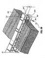
- FIG. 7Aillustrates one embodiment of a jaw member 720 of an electrode assembly 700 for use with an electrosurgical forceps which includes an electrode 721 with a plurality of slots or channels 732a and 732b.
- electrode 721 of jaw member 722 of electrode assembly 700includes a substantially longitudinal, planar, tissue engaging surface 730 which has at least first channel 732a, and typically includes a second channel 732b.
- Each channel 732a and 732bis disposed in a lengthwise direction from a proximal end 705 to a distal end 706 of the electrode 721 so as to divide surface 730 into at least two substantially longitudinal surfaces 730a and 730c.
- a third substantially longitudinal surface 730bis disposed between channels 732a and 732c.
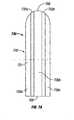
- FIG. 7Bshows upper jaw member 710 of electrode assembly 700. More particularly, upper jaw member 710 is similar to jaw member 720 and includes a corresponding electrode member 711 which has a substantially longitudinal, planar, tissue engaging surface 740. Jaw members 710 and 720 are pivotably connected around a pivot pin 719, and are movable from an open position wherein the jaw members 710 and 720 are disposed in spaced relation relative to one another for manipulating tissue 600, to a clamping or closed position wherein the jaw members 710 and 720 cooperate to grasp tissue 600 therebetween. Jaw members 710 and 720 operate in an analogous manner as described previously with respect to jaw members 280 and 282 (See FIGS. 5A-5C).
- Surface 740includes at least a first channel 742a and typically includes a second channel 742b. Each channel 742a and 742b is disposed in a lengthwise direction from a proximal end 705 to a distal end 706 of the electrode 710 so as to divide surface 740 into surfaces 740a, 740b, and 740c.
- Surface 730 of jaw member 720 and surface 740 of jaw member 710are configured so that channels 742a and 742b substantially correspond to channels 732a and 732b, and consequently, so that the surfaces 730a, 730b and 730c substantially correspond with or are in vertical registration with surfaces 740a, 740b and 740c.
- the corresponding or counterpart channels 732a and 742a, and the corresponding or counterpart channels 732b and 742bform a plurality of corresponding or counterpart electrode surfaces 730a and 740a, 730b and 740b, and 730c and 740c which form tissue seals characterized by potential tissue fluid flow paths. It is envisioned that arranging the electrodes 711 and 721 in this fashion will impede the flow of tissue fluid during the sealing process which allows a stronger seal to develop. In other words, the envisioned electrode 711 and 721 arrangement with channels 732a-732c and 742a-742c inhibits the flow of fluid through the tissue seal, thereby increasing the structural integrity of the tissue seal and decreasing the probability of tissue seal rupture.
- FIG. 8Aillustrates a jaw member 820 of an electrosurgical forceps having an electrode arrangement in accordance with yet another embodiment of the present disclosure.
- an electrode 821 of jaw member 820 of an electrode assembly 800includes a substantially longitudinal, planar, tissue engaging electrode surface 830 which has a plurality of longitudinal and transverse or traversally oriented channels 832a and 832b and 834a to 834c, respectively, which extend lengthwise from proximal end 805 to distal end 806 and across the jaw member 820.
- jaw member 810includes or is characterized by a similar arrangement.
- An electrode 811 of jaw member 810 of electrode assembly 800has a substantially longitudinal, planar tissue engaging surface 840 which includes longitudinal channels 842a and 842b and transverse channels 844a to 844c.
- Jaw member 810 and jaw member 820are pivotably connected around pivot pin 819 such that jaw members 810 and 820 are movable from an open position wherein the jaw members 810 and 820 are disposed in spaced relation relative to one another for manipulating tissue 600, to a clamping or closed position wherein the jaw members 810 and 820 cooperate to grasp tissue 600 therebetween in a similar manner to jaw members 280 and 282 (see FIGS. 5A-5C).
- each jaw member 810 and 820are arranged to complement each other to produce a uniform and effective seal. It is envisioned that the fluid path during sealing will be impeded such that a uniform, reliable and effective seal will develop upon activation of the electrodes 811 and 821.
- FIG. 9Aillustrates a jaw member 920 of an electrosurgical forceps in accordance with still another embodiment of the present disclosure. More particularly, an electrode 921 of jaw member 920 of an electrode assembly 900 has a substantially longitudinal, planar, tissue engaging electrode surface 930.
- the electrode 921includes a proximal end 905 and a distal end 906 and is bounded by first and second lateral side edges 970 and 972, respectively.
- the surface 930includes a first group 931 of substantially longitudinal slots 932 and 934 aligned in a column oriented from the proximal end 905 to the distal end 906.
- the surface 930includes a second group 941 of substantially longitudinal slots 942, 944 and 946 aligned in a column oriented from the proximal end 905 to the distal end 906.
- the first group 931 and the second group 941are disposed on the jaw surface 930 such that the slots 932 and 934 are staggered with respect to the slots 942, 944 and 946.
- jaw member 910includes or is characterized by a similar arrangement.
- An electrode 911 of jaw member 910 of an electrode assembly 900has a substantially longitudinal, planar, tissue engaging electrode surface 950 which includes a first group 951 of substantially longitudinal slots 952 and 954 aligned in a column oriented from a proximal end 907 to a distal end 908.
- the electrode 911is bounded by lateral side edges 974 and 976.
- the surface 950includes a second group 961 of substantially longitudinal slots 962, 964 and 966 aligned in a column oriented from the proximal end 907 to the distal end 908.
- the first group 951 and the second group 961are disposed on the jaw surface 950 such that the slots 952 and 954 are staggered with respect to the slots 962, 964 and 966. Furthermore, the first group 931 corresponds with or is in vertical registration with first group 951. Similarly, the second group 941 corresponds with or is in vertical registration with second group 961. The embodiments are not limited in this context.
- Jaw member 910 and jaw member 920are pivotably connected around pivot pin 919 such that jaw members 910 and 920 are movable from an open position wherein the jaw members 910 and 920 are disposed in spaced relation relative to one another for manipulating tissue 600, to a clamping or closed position wherein the jaw members 910 and 920 cooperate to grasp tissue 600 therebetween in a similar manner to jaw members 280 and 282 (see FIGS. 5A-5C).
- the staggered slot arrangementforms a tissue seal characterized by a plurality of potential flow paths.
- the electrode tissue-engaging surface patterns and channels of each jaw member 910 and 920are arranged to complement each other to produce a uniform and effective seal. It is envisioned that the fluid path during sealing will be impeded such that a uniform, reliable and effective seal will develop upon activation of the electrodes 911 and 921.
- FIGS. 10A and 10Bshow another example of an electrode arrangement across the surface of a jaw member 1020. More particularly, electrode 1021 includes one or more arrays of tissue-engaging surfaces 1032, 1042 and 1052 which are patterned across the jaw surface 1030 to impede fluid flow during activation which is believed to result in a stronger and more reliable seal.
- tissue-engaging surface arrangement of FIGS. 10A and 10Ba similar pattern is envisioned wherein arrays 1032, 1042 and 1052 are disposed within groups to define slots or flow restricting areas 1031 a through 1031f similar to previously described FIGS. 9A and 9B above.
- Jaw housing 1030is made typically from an electrically and thermally insulating material such as a temperature resistant plastic or a ceramic or a cool polymer which thermally conducts heat but which is an electrical insulator. Housing 1030 includes an inwardly facing surface 1025 which supports the various arrays of tissue engaging surfaces 1032, 1042 and 1052.
- the arrays 1032, 1042 and 1052are staggered along the length and width of the jaw surface 1025 with respect to one another. It is believed that this electrode arrangement will further impede fluid flow during electrode activation by forcing fluid flow to occur substantially around the electrodes and substantially through slots or flow restricting areas 1031a through 1031f between the array of surfaces 1032, 1042 and 1052, resulting in a more reliable seal. It is also envisioned that other staggered patterns with a greater or lesser number of surface arrays may be employed to strengthen a tissue seal depending upon a particular tissue type.
- the tissue-engaging surfaces within the arrays 1032, 1042, and 1052are arranged such that the electrode 1021 carries an electrical potential from generator 350 through lead or leads 1060 to tissue upon electrical activation. It is also envisioned that each tissue-engaging surface of each array of tissue-engaging surfaces may be individually connected to the generator 350.
- U.S. Patent Application Serial No.(attorney docket no.: 2886 PCT CIP (203-3427 PCT CIP)) by Odom et al entitled "BIPOLAR FORCEPS WITH MULTIPLE ELECTRODE ARRAY END EFFECTOR ASSEMBLY" discusses several advantages and ways to connect one or more electrodes to accomplish various surgical purposes.
- FIG. 10Bshows opposing arrays of tissue-engaging surfaces 1032 and 1033 of jaw members 1020 and 1010, respectively, each connected to a corresponding common element, e.g., conductive electrodes or plates 1021 and 1031, respectively.
- Each conductive plate 1021 and 1031carries a different electrical potential through a series of conductive connections 1072 and 1082 to each respective array 1032 and 1033.
- arranging the arrays in this fashionfacilitates manufacturing such that arrays 1032 and 1033 and conductive plates 1021 and 1031 may be held in a die or support tool which the outer housings 1030 and 1040 are overmolded.
- the jaw members 1010 and 1020which are pivotably connected at or in the vicinity of their proximal ends 1005 and 1007 around a pivot pin 1019, from an open position wherein the jaw members 1010 and 1020 are disposed in spaced relation relative to one another for approximating tissue 600, to a clamping or closed position wherein the jaw members 1010 and 1020 cooperate to grasp tissue 600 therebetween in a similar manner to jaw members 280 and 282 (see FIGS. 5A-5C).
- tissue engaging surfaces 730, 830, 930, 1030 and 740, 840, 940 and 1040 of the electrodesare disposed as a series of longitudinal strips extending from a proximal end of each jaw member to a distal end thereof, the first and second strips being substantially offset relative to one another.
- Electrodes arrangementsmay be configured for use with either an open forceps as shown in FIG. 1B or an endoscopic forceps as shown in FIG. 1A.
- an open forcepsas shown in FIG. 1B
- an endoscopic forcepsas shown in FIG. 1A.
- One skilled in the artwould recognize that different but known electrical and mechanical considerations would be necessary and apparent to convert an open instrument to an endoscopic instrument to accomplish the same purposes as described herein.
Landscapes
- Health & Medical Sciences (AREA)
- Surgery (AREA)
- Engineering & Computer Science (AREA)
- Life Sciences & Earth Sciences (AREA)
- Biomedical Technology (AREA)
- Otolaryngology (AREA)
- Nuclear Medicine, Radiotherapy & Molecular Imaging (AREA)
- Plasma & Fusion (AREA)
- Physics & Mathematics (AREA)
- Heart & Thoracic Surgery (AREA)
- Medical Informatics (AREA)
- Molecular Biology (AREA)
- Animal Behavior & Ethology (AREA)
- General Health & Medical Sciences (AREA)
- Public Health (AREA)
- Veterinary Medicine (AREA)
- Surgical Instruments (AREA)
Abstract
Description
- The present disclosure relates to forceps used for open and/or endoscopic surgical procedures. More particularly, the present disclosure relates to a forceps which applies a unique combination of mechanical clamping pressure and electrosurgical current to micro-seal soft tissue to promote tissue healing.
- A hemostat or forceps is a simple plier-like tool which uses mechanical action between its jaws to constrict vessels and is commonly used in open surgical procedures to grasp, dissect and/or clamp tissue. Electrosurgical forceps utilize both mechanical clamping action and electrical energy to effect hemostasis by heating the tissue and blood vessels to coagulate, cauterize and/or seal tissue. The electrode of each opposing jaw member is charged to a different electric potential such that when the jaw members grasp tissue, electrical energy can be selectively transferred through the tissue. A surgeon can either cauterize, coagulate/desiccate and/or simply reduce or slow bleeding, by controlling the intensity, frequency and duration of the electrosurgical energy applied between the electrodes and through the tissue.
- For the purposes herein, the term "cauterization" is defined as the use of heat to destroy tissue (also called "diathermy" or "electrodiathermy"). The term "coagulation" is defined as a process of desiccating tissue wherein the tissue cells are ruptured and dried. "Vessel sealing" is defined as the process of liquefying the collagen, elastin and ground substances in the tissue so that it reforms into a fused mass with significantly-reduced demarcation between the opposing tissue structures (opposing walls of the lumen). Coagulation of small vessels is usually sufficient to permanently close them. Larger vessels or tissue need to be sealed to assure permanent closure.
- Commonly-owned U.S. Application
Serial Nos. PCT Application Serial No. PCT/US01/11340 filed on April 6, 2001 by Dycus, et al. entitled "VESSEL SEALER AND DIVIDER",U.S. Application Serial No. 10/116,824 filed on April 5, 2002 by Tetzlaff et al. PCT Application Serial No. PCT/US01/11420 filed on April 6, 2001 by Tetzlaff et al. entitled "VESSEL SEALING INSTRUMENT" teach that to effectively seal tissue or vessels, especially large vessels, two predominant mechanical parameters must be accurately controlled: 1) the pressure applied to the vessel; and 2) the gap distance between the conductive tissue contacting surfaces (electrodes). As can be appreciated, both of these parameters are affected by the thickness of the vessel or tissue being sealed. Accurate application of pressure is important for several reasons: to oppose the walls of the vessel; to reduce the tissue impedance to a low enough value that allows enough electrosurgical energy through the tissue; to overcome the forces of expansion during tissue heating; and to contribute to the end tissue thickness which is an indication of a good seal. It has been determined that a typical sealed vessel wall is optimum between 0.001 inches and 0.006 inches. Below this range, the seal may shred or tear and above this range the lumens may not be properly or effectively sealed. - With respect to smaller vessels, the pressure applied become less relevant and the gap distance between the electrically conductive surfaces becomes more significant for effective sealing. In other words, the chances of the two electrically conductive surfaces touching during activation increases as the tissue thickness and the vessels become smaller.
- As can be appreciated, when cauterizing, coagulating or sealing vessels, the tissue disposed between the two opposing jaw members is essentially destroyed (e.g., heated, ruptured and/or dried with cauterization and coagulation and fused into a single mass with vessel sealing). Other known electrosurgical instruments include blade members or shearing members which simply cut tissue in a mechanical and/or electromechanical manner and, as such, also destroy tissue viability.
- When trying to electrosurgically treat large, soft tissues (e.g., lung, intestine, lymph ducts, etc.) to promote healing, the above-identified surgical treatments are generally impractical due to the fact that in each instance the tissue or a significant portion thereof is essentially destroyed to create the desired surgical effect, cauterization, coagulation and/or sealing. As a result thereof, the tissue is no longer viable across the treatment site, i.e., there remains no feasible path across the tissue for vascularization.
- Thus, a need exists to develop an electrosurgical forceps which effectively treats tissue while maintaining tissue viability across the treatment area to promote tissue healing.
- A need exists also to enhance sealing strength in tissue fusion by increasing resistance to fluid flow or increased pressure at the fusion site so as to minimize entry of fluid into the perimeter of the fused site during burst strength testing. The entry of fluid often results in seal failure due to propagation of the fluid to the center of the tissue seal.
- It is an object of the present disclosure to provide a bipolar electrosurgical forceps having jaw members which are configured with electrode surfaces with a plurality of flow paths so as to increase resistance to fluid flow through the tissue seal zone, or increasing pressure states at the fusion site, thereby increasing tissue seal integrity.
- The present disclosure relates to a bipolar electrosurgical forceps which includes first and second opposing jaw members having respective tissue engaging surfaces associated therewith. The first and second jaw members are adapted for relative movement between an open position to receive tissue and a closed position engaging tissue between the tissue engaging surfaces to effect a tissue seal upon activation of the forceps. The first and second jaw members each include an electrode having a plurality of tissue engaging surfaces which define at least one channel therebetween. The plurality of tissue engaging surfaces of the first jaw member are substantially aligned with the plurality of tissue engaging surfaces of the second jaw member so as to impede fluid flow therebetween and force tissue fluid to flow within the at least one channel during the sealing process.
- In one embodiment, the tissue engaging surfaces of the electrodes are disposed as pairs of longitudinal strips extending from a proximal end of each jaw member to a distal end thereof. At least one traversally oriented channel may be defined between respective tissue engaging surfaces on at least one jaw member.
- In another embodiment, the tissue engaging surfaces of the electrodes are disposed as series of longitudinal strips extending from a proximal end of each jaw member to a distal end thereof, with the first and second strips of the series being substantially offset relative to one another.
- In another embodiment, the tissue engaging surfaces of the electrodes are disposed as series of longitudinal strips extending from a proximal end of each jaw member to a distal end thereof, the first, second and third strips of the series being substantially offset relative to one another.
- Various embodiments of the subject instrument are described herein with reference to the drawings wherein:
- FIG. 1A is a perspective view of an endoscopic forceps having an electrode assembly in accordance with one embodiment of the present disclosure;
- FIG. 1B is a perspective view of an open forceps having a electrode assembly in accordance with one embodiment of the present disclosure;
- FIG. 2 is an enlarged, perspective view of the electrode assembly of the forceps of FIG. 1B shown in an open configuration;
- FIG. 3A is an enlarged, schematic view of one embodiment of the electrode assembly showing a pair of opposing, concentrically-oriented electrodes disposed on a pair of opposing jaw members;
- FIG. 3B is a partial, side cross-sectional view of the electrode assembly of FIG. 3A;
- FIG. 4A is an enlarged, schematic view of another embodiment of the electrode assembly showing a plurality of concentrically-oriented electrode micro-sealing pads disposed on the same jaw member;
- FIG. 4B is a greatly enlarged view of the area of detail in FIG. 4A showing the electrical path during activation of the electrode assembly;
- FIG. 4C is an enlarged schematic view showing the individual micro-sealing sites and viable tissue areas between the two jaw members after activation;
- FIG. 5A is a schematic, perspective view of the jaw members approximating tissue;
- FIG. 5B is a schematic, perspective view of the jaw members grasping tissue; and
- FIG. 5C is a schematic, perspective view showing a series of micro-seals disposed in a pattern across the tissue after activation of the electrode assembly.
- FIG. 6 is plan view of a tissue seal sealed by an electrosurgical forceps according to the prior art showing a potential failure mechanism due to fluid entry into the seal perimeter;
- FIG. 7A is a plan view of one jaw member of an electrosurgical forceps having an electrode with a plurality of slots in accordance with another embodiment of the present disclosure;
- FIG. 7B is a view of a distal end of jaw members of the electrosurgical forceps according to FIG. 7A;
- FIG. 8A is a plan view of one jaw member of an electrosurgical forceps having an electrode with a plurality of slots in accordance with another embodiment of the present disclosure;
- FIG. 8B is a view of a distal end of jaw members of the electrosurgical forceps according to FIG. 8A;
- FIG. 9A is a perspective view of one jaw member of an electrosurgical forceps having an electrode with a plurality of slots in accordance with another embodiment of the present disclosure;
- FIG. 9B is a view of a distal end of jaw members of the electrosurgical forceps according to FIG. 9A;
- FIG. 10A is a plan view of one jaw member of an electrosurgical forceps having an array of individual electrodes in accordance with another embodiment of the present disclosure; and
- FIG. 10B is an elevation view of an end effector assembly of an electrosurgical forceps having jaw members according to FIG. 10A.
- This application incorporates by reference herein in its entirety concurrently filed, commonly owned U.S. Patent Application Serial No. (attorney docket no.: 2886 PCT CIP (203-3427 PCT CIP)) by Odom et al entitled "BIPOLAR FORCEPS WITH MULTIPLE ELECTRODE ARRAY END EFFECTOR ASSEMBLY."
- Referring now to FIG. 1A, a
bipolar forceps 10 is shown for use with various surgical procedures.Forceps 10 generally includes ahousing 20, ahandle assembly 30, a rotatingassembly 80, an activation assembly 70 and anelectrode assembly 110 which mutually cooperate to grasp and seal tissue 600 (See FIGS. 5A-5C). Although the majority of the figure drawings depict abipolar forceps 10 for use in connection with endoscopic surgical procedures, anopen forceps 200 is also contemplated for use in connection with traditional open surgical procedures and is shown by way of example in FIG. 1B and is described below. For the purposes herein, either an endoscopic instrument or an open instrument may be utilized with the electrode assembly described herein. Obviously, different electrical and mechanical connections and considerations apply to each particular type of instrument, however, the novel aspects with respect to the electrode assembly and its operating characteristics remain generally consistent with respect to both the open or endoscopic designs. - More particularly,
forceps 10 includes ashaft 12 which has adistal end 14 dimensioned to mechanically engage ajaw assembly 110 and a proximal end 16 which mechanically engages thehousing 20. Theshaft 12 may be bifurcated at thedistal end 14 thereof to receive thejaw assembly 110. The proximal end 16 ofshaft 12 mechanically engages the rotatingassembly 80 to facilitate rotation of thejaw assembly 110. In the drawings and in the descriptions which follow, the term "proximal", as is traditional, will refer to the end of theforceps 10 which is closer to the user, while the term "distal" will refer to the end which is further from the user. Forceps 10 also includes an electrical interface or plug 300 which connects theforceps 10 to a source of electrosurgical energy, e.g., an electrosurgical generator 350 (See FIG. 3B).Plug 300 includes a pair ofprong members forceps 10 to theelectrosurgical generator 350. Anelectrical cable 310 extends from theplug 300 to asleeve 99 which securely connects thecable 310 to theforceps 10.Cable 310 is internally divided within thehousing 20 to transmit electrosurgical energy through various electrical feed paths to thejaw assembly 110 as explained in more detail below.- Handle
assembly 30 includes a fixedhandle 50 and amovable handle 40. Fixedhandle 50 is integrally associated withhousing 20 and handle 40 is movable relative to fixedhandle 50 to actuate a pair of opposingjaw members jaw assembly 110 as explained in more detail below. The activation assembly 70 is selectively movable by the surgeon to energize thejaw assembly 110.Movable handle 40 and activation assembly 70 are typically of unitary construction and are operatively connected to thehousing 20 and the fixedhandle 50 during the assembly process. - As mentioned above,
jaw assembly 110 is attached to thedistal end 14 ofshaft 12 and includes a pair of opposingjaw members Movable handle 40 ofhandle assembly 30 imparts movement of thejaw members jaw members tissue 600, to a clamping or closed position wherein thejaw members tissue 600 therebetween (See FIGS. 5A-5C). - It is envisioned that the
forceps 10 may be designed such that it is fully or partially disposable depending upon a particular purpose or to achieve a particular result. For example,jaw assembly 110 may be selectively and releasably engageable with thedistal end 14 of theshaft 12 and/or the proximal end 16 ofshaft 12 may be selectively and releasably engageable with thehousing 20 and thehandle assembly 30. In either of these two instances, theforceps 10 would be considered "partially disposable" or "reposable", i.e., a new or different jaw assembly 110 (orjaw assembly 110 and shaft 12) selectively replaces theold jaw assembly 110 as needed. - Referring now to FIGS. 1B and 2, an
open forceps 200 includes a pair ofelongated shaft portions 212a each having aproximal end 216a and 216b, respectively, and adistal end forceps 200 includesjaw assembly 210 which attaches todistal ends shafts Jaw assembly 210 includes opposingjaw members pivot pin 219. - Each
shaft handle 217a and 217b disposed at theproximal end 216a and 216b thereof which each define afinger hole 218a and 218b, respectively, therethrough for receiving a finger of the user. As can be appreciated,finger holes 218a and 218b facilitate movement of theshafts jaw members jaw members tissue 600 to a clamping or closed position wherein thejaw members tissue 600 therebetween. Aratchet 230 is included for selectively locking thejaw members - Each position associated with the cooperating ratchet interfaces 230 holds a specific, i.e., constant, strain energy in the
shaft members jaw members ratchet 230 may include graduations or other visual markings which enable the user to easily and quickly ascertain and control the amount of closure force desired between thejaw members - One of the shafts, e.g., 212b, includes a proximal shaft connector /
flange 221 which is designed to connect theforceps 200 to a source of electrosurgical energy such as an electrosurgical generator 350 (FIG. 3B). More particularly,flange 221 mechanically secureselectrosurgical cable 310 to theforceps 200 such that the user may selectively apply electrosurgical energy as needed. The proximal end of thecable 310 includes asimilar plug 300 as described above with respect to FIG. 1A. The interior ofcable 310 houses a pair of leads which conduct different electrical potentials from theelectrosurgical generator 350 to thejaw members - The
jaw members pivot 219 to effect the grasping oftissue 600. Eachjaw member tissue contacting surface tissue 600 during treatment. - As best shown in FIG. 2, the various electrical connections of the
electrode assembly 210 are typically configured to provide electrical continuity to an array ofelectrode micro-sealing pads 500 of disposed across one or bothjaw members electrical paths electrode micro-sealing pads 500 are typically mechanically and electrically interfaced with corresponding electrical connections (not shown) disposed withinshafts electrical paths shafts - As best shown in FIGS. 4A-4C, the electrical paths are connected to the plurality of
electrode micro-sealing pads 500 within thejaw assembly 210. More particularly, the first electrical path 526 (i.e., an electrical path having a first electrical potential) is connected to eachring electrode 522 of eachelectrode micro-sealing pad 500. The second electrical path 516 (i.e., an electrical path having a second electrical potential) is connected to eachpost electrode 522 of eachelectrode micro-sealing pad 500. - The
electrical paths jaw members tissue 400. Likewise, the movement of thejaw members electrical paths respective connections - As best seen in FIGS. 2-5C,
jaw members tissue contacting surfaces respective jaw member 280 and 284). The non-conductivetissue contacting surfaces tissue contacting surfaces tissue contacting surfaces tissue 600 and may include serrations (not shown) or roughened surfaces to facilitate approximating and grasping tissue. - It is envisioned that one of the jaw members, e.g., 282, includes at least one
stop member 235a, 235b (FIG. 2) disposed on the inner facing surface of the sealing surfaces 286. Alternatively or in addition, one ormore stop members 235a, 235b may be positioned adjacent to the non-conductive sealing surfaces 284, 286 or proximate thepivot 219. Thestop members 235a, 235b are typically designed to define a gap "G" (FIG. 5B) between opposingjaw members more stop members 235a, 235b may be positioned on the distal end and proximal end of one or both of thejaw members electrode micro-sealing pads 500. Moreover, thestop members 235a and 235b may be integrally associated with the non-conductivetissue contacting surfaces electrode micro-sealing pads 500 may also act as stop members for regulating the distance "G" between opposingjaw members 280, 282 (See FIG. 4C). - As mentioned above, the effectiveness of the resulting micro-seal is dependent upon the pressure applied between opposing
jaw members electrode micro-sealing pad 500 at each micro-sealing site 620 (FIG. 4C), the gap "G" between the opposingjaw members 280 and 282 (either regaled by astop member 235a, 235b or the array of electrode micro-sealing pads 500) and the control of the electrosurgical intensity during the micro-sealing process. Applying the correct force is important to oppose the walls of the tissue; to reduce the tissue impedance to a low enough value that allows enough current through the tissue; and to overcome the forces of expansion during tissue heating in addition to contributing towards creating the required end tissue thickness which is an indication of a good micro-seal. Regulating the gap distance and regulating the electrosurgical intensity ensure a consistent seal quality and reduce the likelihood of collateral damage to surrounding tissue. - As best shown in FIG. 2, the
electrode micro-sealing pads 500 are arranged in a longitudinal, pair-like fashion along thetissue contacting surfaces 286 and/or 284. Two or moremicro-sealing pads 500 may extend transversally across thetissue contacting surface 286. FIGS. 3A and 3B show one embodiment of the present disclosure wherein theelectrode micro-sealing pads 500 include aring electrode 422 disposed on onejaw members 282 and apost electrode 412 disposed on theother jaw member 280. Thering electrode 422 includes an insulatingmaterial 424 disposed therein to form a ring electrode andinsulator assembly 420 and thepost electrode 422 includes an insulating material disposed therearound to form a post electrode andinsulator assembly 430. Eachpost electrode assembly 430 and thering electrode assembly 420 of this embodiment together define oneelectrode micro-sealing pad 400. Although shown as a circular-shape,ring electrode 422 may assume any other annular or enclosed configuration or alternatively partially enclosed configuration such as a C-shape arrangement. - As best shown in FIG. 3B, the
post electrode 422 is concentrically centered opposite thering electrode 422 such that when thejaw members tissue 600, electrosurgical energy flows from thering electrode 422, throughtissue 600 and to thepost electrode 412. The insulatingmaterials electrodes post electrode 412 to thering electrode 422 depending upon a particular purpose. - FIGS. 4A-4C show an alternate embodiment of the
jaw assembly 210 according to the present disclosure formicro-sealing tissue 600 wherein eachelectrode micro-sealing pad 500 is disposed on a single jaw member, e.g.,jaw member 280. More particularly and as best illustrated in FIG. 4B, eachelectrode micro-sealing pad 500 consists of aninner post electrode 512 which is surrounded by aninsulative material 514, e.g., ceramic. Theinsulative material 514 is, in turn, encapsulated by aring electrode 522. A second insulative material 535 (or the same insulative material 514) may be configured to encase thering electrode 522 to prevent stray electrical currents to surrounding tissue. - The
ring electrode 522 is connected to theelectrosurgical generator 350 by way of a cable 526 (or other conductive path) which transmits a first electrical potential to eachring electrode 522 atconnection 527. Thepost electrode 512 is connected to theelectrosurgical generator 350 by way of a cable 516 (or other conductive path) which transmits a second electrical potential to eachpost electrode 522 atconnection 517. A controller 375 (See FIG. 4B) may be electrically interposed between thegenerator 350 and theelectrodes - Moreover, a PCB circuit of flex circuit (not shown) may be utilized to provide information relating to the gap distance (e.g., a proximity detector may be employed) between the two
jaw members jaw members generator 350 rotating to one or more of the above parameters either on a continuous basis or upon inquiry from thegenerator 350. For example, a PCB circuit may be employed to control the power, current and/or type of current waveform from thegenerator 350 to thejaw members U.S. Patent No 6,228,080 andU.S. Application Serial No. 10/073,761 the entire contents of both of which are hereby incorporated by reference herein. - In use as depicted in FIGS. 5A-5C, the surgeon initially approximates the tissue (FIG. 5A) between the opposing
jaw member jaw members pivot 219. Once the tissue is grasped, the surgeon selectively activates thegenerator 350 to supply electrosurgical energy to the array of theelectrode micro-sealing pads 500. More particularly, electrosurgical energy flows from thering electrode 522, through thetissue 600 and to the post electrode 512 (See FIGS. 4B and 4C). As a result thereof, an intermittent pattern ofindividual micro-seals 630 is created along and across the tissue 600 (See FIG. 5C). The arrangement of themicro-sealing pads 500 across the tissue only seals the tissue which is between eachmicro-sealing pad 500 and the opposingjaw member 282. The adjacent tissue remains viable which, as can be appreciated, allows blood and nutrients to flow through the sealingsite 620 and between theindividual micro-seals 630 to promote tissue healing and reduce the chances of tissue necrosis. By selectively regulating the closure pressure "F", gap distance "G", and electrosurgical intensity, effective andconsistent micro-seals 630 may be created for many different tissue types. - It is further envisioned that selective ring electrodes and post electrodes may have varying electric potentials upon activation. For example, at or proximate the distal tip of one of the jaw members, one or a series of electrodes may be electrically connected to a first potential and the corresponding electrodes (either on the same jaw or perhaps the opposing jaw) may be connected to a second potential. Towards the proximal end of the jaw member, one or a series of electrodes may be connected to a third potential and the corresponding electrodes connected to yet a fourth potential. As can be appreciated, this would allow different types of tissue sealing to take place at different portions of the jaw members upon activation. For example, the type of sealing could be based upon the type of tissues involved or perhaps the thickness of the tissue. To seal larger tissue, the user would grasp the tissue more towards the proximal portion of the opposing jaw members and to seal smaller tissue, the user would grasp the tissue more towards the distal portion of the jaw members. It is also envisioned that the pattern and/or density of the micro-sealing pads may be configured to seal different types of tissue or thicknesses of tissue along the same jaw members depending upon where the tissue is grasped between opposing jaw members.
- From the foregoing and with reference to the various figure drawings, those skilled in the art will appreciate that certain modifications can also be made to the present disclosure without departing from the scope of the same. For example, it is envisioned that by making the
forceps 100, 200 disposable, theforceps 100, 200 is less likely to become damaged since it is only intended for a single use and, therefore, does not require cleaning or sterilization. As a result, the functionality and consistency of the vital micro-sealing components, e.g., the conductivemicro-sealing electrode pads 500, the stop member(s) 235a, 235b, and theinsulative materials - Experimental results suggest that the magnitude of pressure exerted on the tissue by the micro-sealing pads 112 and 122 is important in assuring a proper surgical outcome, maintaining tissue viability. Tissue pressures within a working range of about 3 kg/cm2 to about 16 kg/cm2 and, more particularly, within a working range of 7 kg/cm2 to 13 kg/cm2 have been shown to be effective for micro-sealing various tissue types and vascular bundles.
- In one embodiment, the
shafts shafts ratchet 230, will yield pressures within the above working range. In addition, the successive positions of the ratchet interfaces increase the pressure between opposing micro-sealing surfaces incrementally within the above working range. - It is envisioned that the outer surface of the
jaw members jaw members 280, 282 (or components thereof) with the surrounding tissue during activation and micro-sealing. Moreover, it is also contemplated that other components such as theshaft portions rings 217a, 217b may also be coated with the same or a different "non-stick" material. Typically, the non-stick materials are of a class of materials that provide a smooth surface to prevent mechanical tooth adhesions. - It is also contemplated that the tissue contacting portions of the electrodes and other portions of the
micro-sealing pads - The non-stick materials may be manufactured from one (or a combination of one or more) of the following "non-stick" materials: nickelchrome, chromium nitride, MedCoat 2000 manufactured by The Electrolizing Corporation of OHIO,
Inconel 600 and tin-nickel.Inconel 600 coating is a so-called "super alloy" which is manufactured by Special Metals, Inc. located in Conroe Texas. The alloy is primarily used in environments which require resistance to corrosion and heat. The high Nickel content ofInconel 600 makes the material especially resistant to organic corrosion. As can be appreciated, these properties are desirable for bipolar electrosurgical instruments which are naturally exposed to high temperatures, high RF energy and organic matter. Moreover, the resistivity ofInconel 600 is typically higher than the base electrode material which further enhances desiccation and micro-seal quality. - One particular class of materials disclosed herein has demonstrated superior non-stick properties and, in some instances, superior micro-seal quality. For example, nitride coatings which include, but not are not limited to: TiN, ZrN, TiAlN, and CrN are preferred materials used for non-stick purposes. CrN has been found to be particularly useful for non-stick purposes due to its overall surface properties and optimal performance. Other classes of materials have also been found to reducing overall sticking. For example, high nickel/chrome alloys with a Ni/Cr ratio of approximately 5:1 have been found to significantly reduce sticking in bipolar instrumentation.
- It is also envisioned that the
micro-sealing pads jaw members tissue 600 between a series ofmicro-sealing pads tissue 600 and/or may be configured to electrosurgically cuttissue 600. - FIG. 6 discloses a resulting tissue seal sealed by an electrosurgical forceps according to the prior art showing a potentially weaker seal area due to entry of fluid into the seal perimeter during sealing. More particularly,
tissue 600 of alumen 602 of a patient's body such as the large or small intestines or any other passage or vessel is subject to atissue seal 604 performed by an electrosurgical forceps of the prior art (not shown). Thetissue seal 604 is typically formed utilizing radiofrequency (RF) energy. Thelumen 602 has an approximate' centerline axis X-X'. Theseal 604 has a perimeter generally of fourcontiguous sides central portion 606. Twosides lumen 602 and parallel to each other, while the twosides side 604a and propagate to thecentral portion 606 of thetissue seal 604. A weaker seal may develop as a result of increased fluid in a particular tissue area. - FIG. 7A illustrates one embodiment of a
jaw member 720 of anelectrode assembly 700 for use with an electrosurgical forceps which includes anelectrode 721 with a plurality of slots orchannels electrode 721 of jaw member 722 ofelectrode assembly 700 includes a substantially longitudinal, planar,tissue engaging surface 730 which has at leastfirst channel 732a, and typically includes asecond channel 732b. Eachchannel proximal end 705 to adistal end 706 of theelectrode 721 so as to dividesurface 730 into at least two substantiallylongitudinal surfaces longitudinal surface 730b is disposed betweenchannels 732a and 732c. - FIG. 7B shows
upper jaw member 710 ofelectrode assembly 700. More particularly,upper jaw member 710 is similar tojaw member 720 and includes acorresponding electrode member 711 which has a substantially longitudinal, planar,tissue engaging surface 740.Jaw members pivot pin 719, and are movable from an open position wherein thejaw members tissue 600, to a clamping or closed position wherein thejaw members tissue 600 therebetween.Jaw members jaw members 280 and 282 (See FIGS. 5A-5C). Surface 740 includes at least afirst channel 742a and typically includes asecond channel 742b. Eachchannel proximal end 705 to adistal end 706 of theelectrode 710 so as to dividesurface 740 into surfaces 740a, 740b, and 740c.Surface 730 ofjaw member 720 andsurface 740 ofjaw member 710 are configured so thatchannels channels surfaces - The corresponding or
counterpart channels counterpart channels counterpart electrode surfaces electrodes electrode channels 732a-732c and 742a-742c inhibits the flow of fluid through the tissue seal, thereby increasing the structural integrity of the tissue seal and decreasing the probability of tissue seal rupture. - FIG. 8A illustrates a
jaw member 820 of an electrosurgical forceps having an electrode arrangement in accordance with yet another embodiment of the present disclosure. More particularly, anelectrode 821 ofjaw member 820 of anelectrode assembly 800 includes a substantially longitudinal, planar, tissue engagingelectrode surface 830 which has a plurality of longitudinal and transverse or traversally orientedchannels proximal end 805 todistal end 806 and across thejaw member 820. - Referring to FIG. 8B,
jaw member 810 includes or is characterized by a similar arrangement. Anelectrode 811 ofjaw member 810 ofelectrode assembly 800 has a substantially longitudinal, planartissue engaging surface 840 which includeslongitudinal channels transverse channels 844a to 844c. Jaw member 810 andjaw member 820 are pivotably connected aroundpivot pin 819 such thatjaw members jaw members tissue 600, to a clamping or closed position wherein thejaw members tissue 600 therebetween in a similar manner tojaw members 280 and 282 (see FIGS. 5A-5C).- Much like the electrode arrangement of FIGS. 7A and 7B, the electrode tissue engaging surface pattern and channels of each
jaw member electrodes - FIG. 9A illustrates a
jaw member 920 of an electrosurgical forceps in accordance with still another embodiment of the present disclosure. More particularly, an electrode 921 ofjaw member 920 of anelectrode assembly 900 has a substantially longitudinal, planar, tissue engagingelectrode surface 930. The electrode 921 includes aproximal end 905 and adistal end 906 and is bounded by first and second lateral side edges 970 and 972, respectively. Thesurface 930 includes afirst group 931 of substantiallylongitudinal slots proximal end 905 to thedistal end 906. In one embodiment, thesurface 930 includes asecond group 941 of substantiallylongitudinal slots proximal end 905 to thedistal end 906. Thefirst group 931 and thesecond group 941 are disposed on thejaw surface 930 such that theslots slots - Referring to FIG. 9B,
jaw member 910 includes or is characterized by a similar arrangement. An electrode 911 ofjaw member 910 of anelectrode assembly 900 has a substantially longitudinal, planar, tissue engagingelectrode surface 950 which includes a first group 951 of substantiallylongitudinal slots proximal end 907 to adistal end 908. The electrode 911 is bounded by lateral side edges 974 and 976. In one embodiment, thesurface 950 includes a second group 961 of substantiallylongitudinal slots proximal end 907 to thedistal end 908. The first group 951 and the second group 961 are disposed on thejaw surface 950 such that theslots slots first group 931 corresponds with or is in vertical registration with first group 951. Similarly, thesecond group 941 corresponds with or is in vertical registration with second group 961. The embodiments are not limited in this context. Jaw member 910 andjaw member 920 are pivotably connected aroundpivot pin 919 such thatjaw members jaw members tissue 600, to a clamping or closed position wherein thejaw members tissue 600 therebetween in a similar manner tojaw members 280 and 282 (see FIGS. 5A-5C).- Yet again, the staggered slot arrangement forms a tissue seal characterized by a plurality of potential flow paths. Much like the electrode arrangements of FIGS. 7A and 7B, and 8A and 8B, the electrode tissue-engaging surface patterns and channels of each
jaw member - FIGS. 10A and 10B show another example of an electrode arrangement across the surface of a
jaw member 1020. More particularly,electrode 1021 includes one or more arrays of tissue-engagingsurfaces jaw surface 1030 to impede fluid flow during activation which is believed to result in a stronger and more reliable seal. In the particular tissue-engaging surface arrangement of FIGS. 10A and 10B, a similar pattern is envisioned whereinarrays flow restricting areas 1031 a through 1031f similar to previously described FIGS. 9A and 9B above.Jaw housing 1030 is made typically from an electrically and thermally insulating material such as a temperature resistant plastic or a ceramic or a cool polymer which thermally conducts heat but which is an electrical insulator.Housing 1030 includes an inwardly facingsurface 1025 which supports the various arrays oftissue engaging surfaces - The
arrays jaw surface 1025 with respect to one another. It is believed that this electrode arrangement will further impede fluid flow during electrode activation by forcing fluid flow to occur substantially around the electrodes and substantially through slots orflow restricting areas 1031a through 1031f between the array ofsurfaces - With particular respect to FIG. 10A, the tissue-engaging surfaces within the
arrays electrode 1021 carries an electrical potential fromgenerator 350 through lead or leads 1060 to tissue upon electrical activation. It is also envisioned that each tissue-engaging surface of each array of tissue-engaging surfaces may be individually connected to thegenerator 350. Commonly owned, concurrently filed U.S. Patent Application Serial No. (attorney docket no.: 2886 PCT CIP (203-3427 PCT CIP)) by Odom et al entitled "BIPOLAR FORCEPS WITH MULTIPLE ELECTRODE ARRAY END EFFECTOR ASSEMBLY" discusses several advantages and ways to connect one or more electrodes to accomplish various surgical purposes. - In one embodiment, FIG. 10B shows opposing arrays of tissue-engaging
surfaces jaw members plates conductive plate conductive connections respective array arrays conductive plates outer housings - The
jaw members proximal ends pivot pin 1019, from an open position wherein thejaw members tissue 600, to a clamping or closed position wherein thejaw members tissue 600 therebetween in a similar manner tojaw members 280 and 282 (see FIGS. 5A-5C). - It is envisioned that the
tissue engaging surfaces - It is also contemplated that the various aforedescribed electrode arrangements may be configured for use with either an open forceps as shown in FIG. 1B or an endoscopic forceps as shown in FIG. 1A. One skilled in the art would recognize that different but known electrical and mechanical considerations would be necessary and apparent to convert an open instrument to an endoscopic instrument to accomplish the same purposes as described herein.
- While several embodiments of the disclosure have been shown in the drawings, it is not intended that the disclosure be limited thereto, as it is intended that the disclosure be as broad in scope as the art will allow and that the specification be read likewise. Therefore, the above description should not be construed as limiting, but merely as exemplifications of preferred embodiments. Those skilled in the art will envision other modifications within the scope and spirit of the claims appended hereto.
Claims (6)
- A bipolar electrosurgical forceps, comprising:first and second opposing jaw members having respective tissue engaging surfaces associated therewith, the first and second jaw members adapted for relative movement between an open position to receive tissue and a closed position engaging tissue between said tissue engaging surfaces to effect a tissue seal upon activation of the forceps;the first and second jaw members each including an electrode having a plurality of tissue engaging surfaces which define at least one channel therebetween,the plurality of tissue engaging surfaces of the first jaw member being substantially aligned with the plurality of tissue engaging surfaces of the second jaw member so as to impede fluid flow therebetween and force tissue fluid to flow within the at least one channel during the sealing process.
- A bipolar electrosurgical forceps according to claim 1, wherein the tissue engaging surfaces of the electrodes are disposed as pairs of longitudinal strips extending from a proximal end of each jaw member to a distal end thereof.
- A bipolar electrosurgical forceps according to claim 2, wherein at least one traversally oriented channel is defined between respective tissue engaging surfaces on at least one jaw member.
- A bipolar electrosurgical forceps according to claim 1, wherein the tissue engaging surfaces of the electrodes are disposed as a series of longitudinal strips extending from a proximal end of each jaw member to a distal end thereof, the first and second strips of the series being substantially offset relative to one another.
- A bipolar electrosurgical forceps according to claim 1, wherein the tissue engaging surfaces of the electrodes are disposed as series of longitudinal strips extending from a proximal end of each jaw member to a distal end thereof, the first, second and third strips of the series being substantially offset relative to one another.
- A bipolar electrosurgical forceps, comprising:first and second opposing jaw members each having electrodes with a plurality of respective tissue engaging surfaces associated therewith, the first and second jaw members adapted for relative movement between an open position to receive tissue and a closed position engaging tissue between the tissue engaging surfaces;the tissue engaging surfaces of the first jaw member aligned in a plurality of at least two columns;the tissue engaging surfaces of the second jaw member aligned in a plurality of at least two columns;each of the tissue engaging surfaces in at least the first column of the first jaw member being aligned with a corresponding tissue engaging surface in at least the first column of the second jaw member when the first and second jaw members are in the closed position to form individual corresponding pairs of tissue engaging surfaces between the first and second jaw members, andeach of the tissue engaging surfaces in at least the second column of the first jaw member being aligned with a corresponding tissue engaging surface in at least the second column of the second jaw member when the first and second jaw members are in the closed position to form individual corresponding pairs of tissue engaging surfaces between the first and second jaw members,such that upon energization, electrosurgical energy communicates between each of the individual corresponding pairs of tissue engaging surfaces in the first and second jaw members.
Priority Applications (1)
| Application Number | Priority Date | Filing Date | Title |
|---|---|---|---|
| EP20050020666EP1767164B1 (en) | 2005-09-22 | 2005-09-22 | Electrode assembly for tissue fusion |
Applications Claiming Priority (1)
| Application Number | Priority Date | Filing Date | Title |
|---|---|---|---|
| EP20050020666EP1767164B1 (en) | 2005-09-22 | 2005-09-22 | Electrode assembly for tissue fusion |
Publications (2)
| Publication Number | Publication Date |
|---|---|
| EP1767164A1true EP1767164A1 (en) | 2007-03-28 |
| EP1767164B1 EP1767164B1 (en) | 2013-01-09 |
Family
ID=35784690
Family Applications (1)
| Application Number | Title | Priority Date | Filing Date |
|---|---|---|---|
| EP20050020666CeasedEP1767164B1 (en) | 2005-09-22 | 2005-09-22 | Electrode assembly for tissue fusion |
Country Status (1)
| Country | Link |
|---|---|
| EP (1) | EP1767164B1 (en) |
Cited By (35)
| Publication number | Priority date | Publication date | Assignee | Title |
|---|---|---|---|---|
| EP2455033A1 (en)* | 2010-11-17 | 2012-05-23 | Tyco Healthcare Group, LP | Apparatus for vascular tissue sealing with reduced energy consumption |
| US8419727B2 (en) | 2010-03-26 | 2013-04-16 | Aesculap Ag | Impedance mediated power delivery for electrosurgery |
| US8574229B2 (en) | 2006-05-02 | 2013-11-05 | Aesculap Ag | Surgical tool |
| US8696662B2 (en) | 2005-05-12 | 2014-04-15 | Aesculap Ag | Electrocautery method and apparatus |
| US8728072B2 (en) | 2005-05-12 | 2014-05-20 | Aesculap Ag | Electrocautery method and apparatus |
| US8827992B2 (en) | 2010-03-26 | 2014-09-09 | Aesculap Ag | Impedance mediated control of power delivery for electrosurgery |
| US8870867B2 (en) | 2008-02-06 | 2014-10-28 | Aesculap Ag | Articulable electrosurgical instrument with a stabilizable articulation actuator |
| US8888770B2 (en) | 2005-05-12 | 2014-11-18 | Aesculap Ag | Apparatus for tissue cauterization |
| US9173698B2 (en) | 2010-09-17 | 2015-11-03 | Aesculap Ag | Electrosurgical tissue sealing augmented with a seal-enhancing composition |
| US9339323B2 (en) | 2005-05-12 | 2016-05-17 | Aesculap Ag | Electrocautery method and apparatus |
| US9872724B2 (en) | 2012-09-26 | 2018-01-23 | Aesculap Ag | Apparatus for tissue cutting and sealing |
| US9918778B2 (en) | 2006-05-02 | 2018-03-20 | Aesculap Ag | Laparoscopic radiofrequency surgical device |
| US10004555B2 (en) | 2011-06-28 | 2018-06-26 | Aesculap Ag | Electrosurgical tissue dissecting device |
| US10154848B2 (en) | 2011-07-11 | 2018-12-18 | Covidien Lp | Stand alone energy-based tissue clips |
| US10303641B2 (en) | 2014-05-07 | 2019-05-28 | Covidien Lp | Authentication and information system for reusable surgical instruments |
| US10335183B2 (en) | 2012-06-29 | 2019-07-02 | Ethicon Llc | Feedback devices for surgical control systems |
| US10335182B2 (en) | 2012-06-29 | 2019-07-02 | Ethicon Llc | Surgical instruments with articulating shafts |
| US10335614B2 (en) | 2008-08-06 | 2019-07-02 | Ethicon Llc | Devices and techniques for cutting and coagulating tissue |
| US10342602B2 (en) | 2015-03-17 | 2019-07-09 | Ethicon Llc | Managing tissue treatment |
| US10349999B2 (en) | 2014-03-31 | 2019-07-16 | Ethicon Llc | Controlling impedance rise in electrosurgical medical devices |
| US10357303B2 (en) | 2015-06-30 | 2019-07-23 | Ethicon Llc | Translatable outer tube for sealing using shielded lap chole dissector |
| US10376305B2 (en) | 2016-08-05 | 2019-08-13 | Ethicon Llc | Methods and systems for advanced harmonic energy |
| US10383649B2 (en) | 2011-01-14 | 2019-08-20 | Covidien Lp | Trigger lockout and kickback mechanism for surgical instruments |
| US10398466B2 (en) | 2007-07-27 | 2019-09-03 | Ethicon Llc | Ultrasonic end effectors with increased active length |
| US10420580B2 (en) | 2016-08-25 | 2019-09-24 | Ethicon Llc | Ultrasonic transducer for surgical instrument |
| US10420579B2 (en) | 2007-07-31 | 2019-09-24 | Ethicon Llc | Surgical instruments |
| US10426507B2 (en) | 2007-07-31 | 2019-10-01 | Ethicon Llc | Ultrasonic surgical instruments |
| US10433900B2 (en) | 2011-07-22 | 2019-10-08 | Ethicon Llc | Surgical instruments for tensioning tissue |
| US10433865B2 (en) | 2007-11-30 | 2019-10-08 | Ethicon Llc | Ultrasonic surgical blades |
| US10441308B2 (en) | 2007-11-30 | 2019-10-15 | Ethicon Llc | Ultrasonic surgical instrument blades |
| US10441350B2 (en) | 2003-11-17 | 2019-10-15 | Covidien Ag | Bipolar forceps having monopolar extension |
| US10441345B2 (en) | 2009-10-09 | 2019-10-15 | Ethicon Llc | Surgical generator for ultrasonic and electrosurgical devices |
| US10441310B2 (en) | 2012-06-29 | 2019-10-15 | Ethicon Llc | Surgical instruments with curved section |
| US10456193B2 (en) | 2016-05-03 | 2019-10-29 | Ethicon Llc | Medical device with a bilateral jaw configuration for nerve stimulation |
| US10463421B2 (en) | 2014-03-27 | 2019-11-05 | Ethicon Llc | Two stage trigger, clamp and cut bipolar vessel sealer |
Families Citing this family (134)
| Publication number | Priority date | Publication date | Assignee | Title |
|---|---|---|---|---|
| US7364577B2 (en) | 2002-02-11 | 2008-04-29 | Sherwood Services Ag | Vessel sealing system |
| US11229472B2 (en) | 2001-06-12 | 2022-01-25 | Cilag Gmbh International | Modular battery powered handheld surgical instrument with multiple magnetic position sensors |
| US8182501B2 (en) | 2004-02-27 | 2012-05-22 | Ethicon Endo-Surgery, Inc. | Ultrasonic surgical shears and method for sealing a blood vessel using same |
| US20060079879A1 (en) | 2004-10-08 | 2006-04-13 | Faller Craig N | Actuation mechanism for use with an ultrasonic surgical instrument |
| US20070191713A1 (en) | 2005-10-14 | 2007-08-16 | Eichmann Stephen E | Ultrasonic device for cutting and coagulating |
| US7621930B2 (en) | 2006-01-20 | 2009-11-24 | Ethicon Endo-Surgery, Inc. | Ultrasound medical instrument having a medical ultrasonic blade |
| US8911460B2 (en) | 2007-03-22 | 2014-12-16 | Ethicon Endo-Surgery, Inc. | Ultrasonic surgical instruments |
| US8142461B2 (en) | 2007-03-22 | 2012-03-27 | Ethicon Endo-Surgery, Inc. | Surgical instruments |
| US8808319B2 (en) | 2007-07-27 | 2014-08-19 | Ethicon Endo-Surgery, Inc. | Surgical instruments |
| US9044261B2 (en) | 2007-07-31 | 2015-06-02 | Ethicon Endo-Surgery, Inc. | Temperature controlled ultrasonic surgical instruments |
| EP2217157A2 (en) | 2007-10-05 | 2010-08-18 | Ethicon Endo-Surgery, Inc. | Ergonomic surgical instruments |
| US8142473B2 (en) | 2008-10-03 | 2012-03-27 | Tyco Healthcare Group Lp | Method of transferring rotational motion in an articulating surgical instrument |
| US9700339B2 (en) | 2009-05-20 | 2017-07-11 | Ethicon Endo-Surgery, Inc. | Coupling arrangements and methods for attaching tools to ultrasonic surgical instruments |
| US8246618B2 (en) | 2009-07-08 | 2012-08-21 | Tyco Healthcare Group Lp | Electrosurgical jaws with offset knife |
| US8663220B2 (en) | 2009-07-15 | 2014-03-04 | Ethicon Endo-Surgery, Inc. | Ultrasonic surgical instruments |
| US10172669B2 (en) | 2009-10-09 | 2019-01-08 | Ethicon Llc | Surgical instrument comprising an energy trigger lockout |
| US9050093B2 (en) | 2009-10-09 | 2015-06-09 | Ethicon Endo-Surgery, Inc. | Surgical generator for ultrasonic and electrosurgical devices |
| US11090104B2 (en) | 2009-10-09 | 2021-08-17 | Cilag Gmbh International | Surgical generator for ultrasonic and electrosurgical devices |
| US8469981B2 (en) | 2010-02-11 | 2013-06-25 | Ethicon Endo-Surgery, Inc. | Rotatable cutting implement arrangements for ultrasonic surgical instruments |
| US8951272B2 (en) | 2010-02-11 | 2015-02-10 | Ethicon Endo-Surgery, Inc. | Seal arrangements for ultrasonically powered surgical instruments |
| US8486096B2 (en) | 2010-02-11 | 2013-07-16 | Ethicon Endo-Surgery, Inc. | Dual purpose surgical instrument for cutting and coagulating tissue |
| US8834518B2 (en) | 2010-04-12 | 2014-09-16 | Ethicon Endo-Surgery, Inc. | Electrosurgical cutting and sealing instruments with cam-actuated jaws |
| GB2480498A (en) | 2010-05-21 | 2011-11-23 | Ethicon Endo Surgery Inc | Medical device comprising RF circuitry |
| US8795327B2 (en) | 2010-07-22 | 2014-08-05 | Ethicon Endo-Surgery, Inc. | Electrosurgical instrument with separate closure and cutting members |
| US9192431B2 (en) | 2010-07-23 | 2015-11-24 | Ethicon Endo-Surgery, Inc. | Electrosurgical cutting and sealing instrument |
| US9044243B2 (en) | 2011-08-30 | 2015-06-02 | Ethcon Endo-Surgery, Inc. | Surgical cutting and fastening device with descendible second trigger arrangement |
| US9333025B2 (en) | 2011-10-24 | 2016-05-10 | Ethicon Endo-Surgery, Llc | Battery initialization clip |
| WO2013119545A1 (en) | 2012-02-10 | 2013-08-15 | Ethicon-Endo Surgery, Inc. | Robotically controlled surgical instrument |
| US9439668B2 (en) | 2012-04-09 | 2016-09-13 | Ethicon Endo-Surgery, Llc | Switch arrangements for ultrasonic surgical instruments |
| US20140005705A1 (en) | 2012-06-29 | 2014-01-02 | Ethicon Endo-Surgery, Inc. | Surgical instruments with articulating shafts |
| US9351754B2 (en) | 2012-06-29 | 2016-05-31 | Ethicon Endo-Surgery, Llc | Ultrasonic surgical instruments with distally positioned jaw assemblies |
| US9820768B2 (en) | 2012-06-29 | 2017-11-21 | Ethicon Llc | Ultrasonic surgical instruments with control mechanisms |
| US9326788B2 (en) | 2012-06-29 | 2016-05-03 | Ethicon Endo-Surgery, Llc | Lockout mechanism for use with robotic electrosurgical device |
| US9226767B2 (en) | 2012-06-29 | 2016-01-05 | Ethicon Endo-Surgery, Inc. | Closed feedback control for electrosurgical device |
| US20140005702A1 (en) | 2012-06-29 | 2014-01-02 | Ethicon Endo-Surgery, Inc. | Ultrasonic surgical instruments with distally positioned transducers |
| EP2900158B1 (en) | 2012-09-28 | 2020-04-15 | Ethicon LLC | Multi-function bi-polar forceps |
| US9095367B2 (en) | 2012-10-22 | 2015-08-04 | Ethicon Endo-Surgery, Inc. | Flexible harmonic waveguides/blades for surgical instruments |
| US20140135804A1 (en) | 2012-11-15 | 2014-05-15 | Ethicon Endo-Surgery, Inc. | Ultrasonic and electrosurgical devices |
| US10226273B2 (en) | 2013-03-14 | 2019-03-12 | Ethicon Llc | Mechanical fasteners for use with surgical energy devices |
| US9814514B2 (en) | 2013-09-13 | 2017-11-14 | Ethicon Llc | Electrosurgical (RF) medical instruments for cutting and coagulating tissue |
| US9265926B2 (en) | 2013-11-08 | 2016-02-23 | Ethicon Endo-Surgery, Llc | Electrosurgical devices |
| GB2521229A (en) | 2013-12-16 | 2015-06-17 | Ethicon Endo Surgery Inc | Medical device |
| GB2521228A (en) | 2013-12-16 | 2015-06-17 | Ethicon Endo Surgery Inc | Medical device |
| US9795436B2 (en) | 2014-01-07 | 2017-10-24 | Ethicon Llc | Harvesting energy from a surgical generator |
| US9554854B2 (en) | 2014-03-18 | 2017-01-31 | Ethicon Endo-Surgery, Llc | Detecting short circuits in electrosurgical medical devices |
| US10092310B2 (en) | 2014-03-27 | 2018-10-09 | Ethicon Llc | Electrosurgical devices |
| US10524852B1 (en) | 2014-03-28 | 2020-01-07 | Ethicon Llc | Distal sealing end effector with spacers |
| US9913680B2 (en) | 2014-04-15 | 2018-03-13 | Ethicon Llc | Software algorithms for electrosurgical instruments |
| US9757186B2 (en) | 2014-04-17 | 2017-09-12 | Ethicon Llc | Device status feedback for bipolar tissue spacer |
| US10285724B2 (en) | 2014-07-31 | 2019-05-14 | Ethicon Llc | Actuation mechanisms and load adjustment assemblies for surgical instruments |
| US10194976B2 (en) | 2014-08-25 | 2019-02-05 | Ethicon Llc | Lockout disabling mechanism |
| US9877776B2 (en) | 2014-08-25 | 2018-01-30 | Ethicon Llc | Simultaneous I-beam and spring driven cam jaw closure mechanism |
| US10194972B2 (en) | 2014-08-26 | 2019-02-05 | Ethicon Llc | Managing tissue treatment |
| US10639092B2 (en) | 2014-12-08 | 2020-05-05 | Ethicon Llc | Electrode configurations for surgical instruments |
| US10159524B2 (en) | 2014-12-22 | 2018-12-25 | Ethicon Llc | High power battery powered RF amplifier topology |
| US9848937B2 (en) | 2014-12-22 | 2017-12-26 | Ethicon Llc | End effector with detectable configurations |
| US10092348B2 (en) | 2014-12-22 | 2018-10-09 | Ethicon Llc | RF tissue sealer, shear grip, trigger lock mechanism and energy activation |
| US10111699B2 (en) | 2014-12-22 | 2018-10-30 | Ethicon Llc | RF tissue sealer, shear grip, trigger lock mechanism and energy activation |
| US10245095B2 (en) | 2015-02-06 | 2019-04-02 | Ethicon Llc | Electrosurgical instrument with rotation and articulation mechanisms |
| US10321950B2 (en) | 2015-03-17 | 2019-06-18 | Ethicon Llc | Managing tissue treatment |
| US10595929B2 (en) | 2015-03-24 | 2020-03-24 | Ethicon Llc | Surgical instruments with firing system overload protection mechanisms |
| US10314638B2 (en) | 2015-04-07 | 2019-06-11 | Ethicon Llc | Articulating radio frequency (RF) tissue seal with articulating state sensing |
| US10117702B2 (en) | 2015-04-10 | 2018-11-06 | Ethicon Llc | Surgical generator systems and related methods |
| US10130410B2 (en) | 2015-04-17 | 2018-11-20 | Ethicon Llc | Electrosurgical instrument including a cutting member decouplable from a cutting member trigger |
| US9872725B2 (en) | 2015-04-29 | 2018-01-23 | Ethicon Llc | RF tissue sealer with mode selection |
| US11020140B2 (en) | 2015-06-17 | 2021-06-01 | Cilag Gmbh International | Ultrasonic surgical blade for use with ultrasonic surgical instruments |
| US10034704B2 (en) | 2015-06-30 | 2018-07-31 | Ethicon Llc | Surgical instrument with user adaptable algorithms |
| US10898256B2 (en) | 2015-06-30 | 2021-01-26 | Ethicon Llc | Surgical system with user adaptable techniques based on tissue impedance |
| US11129669B2 (en) | 2015-06-30 | 2021-09-28 | Cilag Gmbh International | Surgical system with user adaptable techniques based on tissue type |
| US11141213B2 (en) | 2015-06-30 | 2021-10-12 | Cilag Gmbh International | Surgical instrument with user adaptable techniques |
| US11051873B2 (en) | 2015-06-30 | 2021-07-06 | Cilag Gmbh International | Surgical system with user adaptable techniques employing multiple energy modalities based on tissue parameters |
| US10154852B2 (en) | 2015-07-01 | 2018-12-18 | Ethicon Llc | Ultrasonic surgical blade with improved cutting and coagulation features |
| US10194973B2 (en) | 2015-09-30 | 2019-02-05 | Ethicon Llc | Generator for digitally generating electrical signal waveforms for electrosurgical and ultrasonic surgical instruments |
| US10595930B2 (en) | 2015-10-16 | 2020-03-24 | Ethicon Llc | Electrode wiping surgical device |
| US10959771B2 (en) | 2015-10-16 | 2021-03-30 | Ethicon Llc | Suction and irrigation sealing grasper |
| US10959806B2 (en) | 2015-12-30 | 2021-03-30 | Ethicon Llc | Energized medical device with reusable handle |
| US10179022B2 (en) | 2015-12-30 | 2019-01-15 | Ethicon Llc | Jaw position impedance limiter for electrosurgical instrument |
| US10575892B2 (en) | 2015-12-31 | 2020-03-03 | Ethicon Llc | Adapter for electrical surgical instruments |
| US11051840B2 (en) | 2016-01-15 | 2021-07-06 | Ethicon Llc | Modular battery powered handheld surgical instrument with reusable asymmetric handle housing |
| US10716615B2 (en) | 2016-01-15 | 2020-07-21 | Ethicon Llc | Modular battery powered handheld surgical instrument with curved end effectors having asymmetric engagement between jaw and blade |
| US11129670B2 (en) | 2016-01-15 | 2021-09-28 | Cilag Gmbh International | Modular battery powered handheld surgical instrument with selective application of energy based on button displacement, intensity, or local tissue characterization |
| US11229471B2 (en) | 2016-01-15 | 2022-01-25 | Cilag Gmbh International | Modular battery powered handheld surgical instrument with selective application of energy based on tissue characterization |
| US12193698B2 (en) | 2016-01-15 | 2025-01-14 | Cilag Gmbh International | Method for self-diagnosing operation of a control switch in a surgical instrument system |
| US10555769B2 (en) | 2016-02-22 | 2020-02-11 | Ethicon Llc | Flexible circuits for electrosurgical instrument |
| US10646269B2 (en) | 2016-04-29 | 2020-05-12 | Ethicon Llc | Non-linear jaw gap for electrosurgical instruments |
| US10856934B2 (en) | 2016-04-29 | 2020-12-08 | Ethicon Llc | Electrosurgical instrument with electrically conductive gap setting and tissue engaging members |
| US10485607B2 (en) | 2016-04-29 | 2019-11-26 | Ethicon Llc | Jaw structure with distal closure for electrosurgical instruments |
| US10987156B2 (en) | 2016-04-29 | 2021-04-27 | Ethicon Llc | Electrosurgical instrument with electrically conductive gap setting member and electrically insulative tissue engaging members |
| US10702329B2 (en) | 2016-04-29 | 2020-07-07 | Ethicon Llc | Jaw structure with distal post for electrosurgical instruments |
| US10245064B2 (en) | 2016-07-12 | 2019-04-02 | Ethicon Llc | Ultrasonic surgical instrument with piezoelectric central lumen transducer |
| US10893883B2 (en) | 2016-07-13 | 2021-01-19 | Ethicon Llc | Ultrasonic assembly for use with ultrasonic surgical instruments |
| US10842522B2 (en) | 2016-07-15 | 2020-11-24 | Ethicon Llc | Ultrasonic surgical instruments having offset blades |
| US10285723B2 (en) | 2016-08-09 | 2019-05-14 | Ethicon Llc | Ultrasonic surgical blade with improved heel portion |
| USD847990S1 (en) | 2016-08-16 | 2019-05-07 | Ethicon Llc | Surgical instrument |
| US10952759B2 (en) | 2016-08-25 | 2021-03-23 | Ethicon Llc | Tissue loading of a surgical instrument |
| US10751117B2 (en) | 2016-09-23 | 2020-08-25 | Ethicon Llc | Electrosurgical instrument with fluid diverter |
| US10603064B2 (en) | 2016-11-28 | 2020-03-31 | Ethicon Llc | Ultrasonic transducer |
| US11266430B2 (en) | 2016-11-29 | 2022-03-08 | Cilag Gmbh International | End effector control and calibration |
| US11033325B2 (en) | 2017-02-16 | 2021-06-15 | Cilag Gmbh International | Electrosurgical instrument with telescoping suction port and debris cleaner |
| US10799284B2 (en) | 2017-03-15 | 2020-10-13 | Ethicon Llc | Electrosurgical instrument with textured jaws |
| US11497546B2 (en) | 2017-03-31 | 2022-11-15 | Cilag Gmbh International | Area ratios of patterned coatings on RF electrodes to reduce sticking |
| US10603117B2 (en) | 2017-06-28 | 2020-03-31 | Ethicon Llc | Articulation state detection mechanisms |
| US10820920B2 (en) | 2017-07-05 | 2020-11-03 | Ethicon Llc | Reusable ultrasonic medical devices and methods of their use |
| US11033323B2 (en) | 2017-09-29 | 2021-06-15 | Cilag Gmbh International | Systems and methods for managing fluid and suction in electrosurgical systems |
| US11490951B2 (en) | 2017-09-29 | 2022-11-08 | Cilag Gmbh International | Saline contact with electrodes |
| US11484358B2 (en) | 2017-09-29 | 2022-11-01 | Cilag Gmbh International | Flexible electrosurgical instrument |
| US11452525B2 (en) | 2019-12-30 | 2022-09-27 | Cilag Gmbh International | Surgical instrument comprising an adjustment system |
| US12023086B2 (en) | 2019-12-30 | 2024-07-02 | Cilag Gmbh International | Electrosurgical instrument for delivering blended energy modalities to tissue |
| US11812957B2 (en) | 2019-12-30 | 2023-11-14 | Cilag Gmbh International | Surgical instrument comprising a signal interference resolution system |
| US12114912B2 (en) | 2019-12-30 | 2024-10-15 | Cilag Gmbh International | Non-biased deflectable electrode to minimize contact between ultrasonic blade and electrode |
| US11779329B2 (en) | 2019-12-30 | 2023-10-10 | Cilag Gmbh International | Surgical instrument comprising a flex circuit including a sensor system |
| US11937866B2 (en) | 2019-12-30 | 2024-03-26 | Cilag Gmbh International | Method for an electrosurgical procedure |
| US12064109B2 (en) | 2019-12-30 | 2024-08-20 | Cilag Gmbh International | Surgical instrument comprising a feedback control circuit |
| US11696776B2 (en) | 2019-12-30 | 2023-07-11 | Cilag Gmbh International | Articulatable surgical instrument |
| US11911063B2 (en) | 2019-12-30 | 2024-02-27 | Cilag Gmbh International | Techniques for detecting ultrasonic blade to electrode contact and reducing power to ultrasonic blade |
| US20210196357A1 (en) | 2019-12-30 | 2021-07-01 | Ethicon Llc | Electrosurgical instrument with asynchronous energizing electrodes |
| US12262937B2 (en) | 2019-12-30 | 2025-04-01 | Cilag Gmbh International | User interface for surgical instrument with combination energy modality end-effector |
| US11786291B2 (en) | 2019-12-30 | 2023-10-17 | Cilag Gmbh International | Deflectable support of RF energy electrode with respect to opposing ultrasonic blade |
| US11937863B2 (en) | 2019-12-30 | 2024-03-26 | Cilag Gmbh International | Deflectable electrode with variable compression bias along the length of the deflectable electrode |
| US12343063B2 (en) | 2019-12-30 | 2025-07-01 | Cilag Gmbh International | Multi-layer clamp arm pad for enhanced versatility and performance of a surgical device |
| US11986201B2 (en) | 2019-12-30 | 2024-05-21 | Cilag Gmbh International | Method for operating a surgical instrument |
| US11950797B2 (en) | 2019-12-30 | 2024-04-09 | Cilag Gmbh International | Deflectable electrode with higher distal bias relative to proximal bias |
| US11779387B2 (en) | 2019-12-30 | 2023-10-10 | Cilag Gmbh International | Clamp arm jaw to minimize tissue sticking and improve tissue control |
| US11684412B2 (en) | 2019-12-30 | 2023-06-27 | Cilag Gmbh International | Surgical instrument with rotatable and articulatable surgical end effector |
| US12053224B2 (en) | 2019-12-30 | 2024-08-06 | Cilag Gmbh International | Variation in electrode parameters and deflectable electrode to modify energy density and tissue interaction |
| US12336747B2 (en) | 2019-12-30 | 2025-06-24 | Cilag Gmbh International | Method of operating a combination ultrasonic / bipolar RF surgical device with a combination energy modality end-effector |
| US11660089B2 (en) | 2019-12-30 | 2023-05-30 | Cilag Gmbh International | Surgical instrument comprising a sensing system |
| US11944366B2 (en) | 2019-12-30 | 2024-04-02 | Cilag Gmbh International | Asymmetric segmented ultrasonic support pad for cooperative engagement with a movable RF electrode |
| US20210196362A1 (en) | 2019-12-30 | 2021-07-01 | Ethicon Llc | Electrosurgical end effectors with thermally insulative and thermally conductive portions |
| US11786294B2 (en) | 2019-12-30 | 2023-10-17 | Cilag Gmbh International | Control program for modular combination energy device |
| US12082808B2 (en) | 2019-12-30 | 2024-09-10 | Cilag Gmbh International | Surgical instrument comprising a control system responsive to software configurations |
| US12076006B2 (en) | 2019-12-30 | 2024-09-03 | Cilag Gmbh International | Surgical instrument comprising an orientation detection system |
| US11844562B2 (en) | 2020-03-23 | 2023-12-19 | Covidien Lp | Electrosurgical forceps for grasping, treating, and/or dividing tissue |
| US11957342B2 (en) | 2021-11-01 | 2024-04-16 | Cilag Gmbh International | Devices, systems, and methods for detecting tissue and foreign objects during a surgical operation |
Citations (4)
| Publication number | Priority date | Publication date | Assignee | Title |
|---|---|---|---|---|
| EP0875209A1 (en)* | 1997-04-04 | 1998-11-04 | Ethicon Endo-Surgery, Inc. | Electrosurgical hemostatic and stapling device |
| EP0986990A1 (en)* | 1997-06-18 | 2000-03-22 | Eggers & Associates, Inc. | Electrosurgical forceps |
| WO2004082495A1 (en)* | 2003-03-13 | 2004-09-30 | Sherwood Services Ag | Bipolar concentric electrode assembly for soft tissue fusion |
| US20050033278A1 (en)* | 2001-09-05 | 2005-02-10 | Mcclurken Michael | Fluid assisted medical devices, fluid delivery systems and controllers for such devices, and methods |
- 2005
- 2005-09-22EPEP20050020666patent/EP1767164B1/ennot_activeCeased
Patent Citations (4)
| Publication number | Priority date | Publication date | Assignee | Title |
|---|---|---|---|---|
| EP0875209A1 (en)* | 1997-04-04 | 1998-11-04 | Ethicon Endo-Surgery, Inc. | Electrosurgical hemostatic and stapling device |
| EP0986990A1 (en)* | 1997-06-18 | 2000-03-22 | Eggers & Associates, Inc. | Electrosurgical forceps |
| US20050033278A1 (en)* | 2001-09-05 | 2005-02-10 | Mcclurken Michael | Fluid assisted medical devices, fluid delivery systems and controllers for such devices, and methods |
| WO2004082495A1 (en)* | 2003-03-13 | 2004-09-30 | Sherwood Services Ag | Bipolar concentric electrode assembly for soft tissue fusion |
Cited By (49)
| Publication number | Priority date | Publication date | Assignee | Title |
|---|---|---|---|---|
| US10441350B2 (en) | 2003-11-17 | 2019-10-15 | Covidien Ag | Bipolar forceps having monopolar extension |
| US9339323B2 (en) | 2005-05-12 | 2016-05-17 | Aesculap Ag | Electrocautery method and apparatus |
| US8696662B2 (en) | 2005-05-12 | 2014-04-15 | Aesculap Ag | Electrocautery method and apparatus |
| US8728072B2 (en) | 2005-05-12 | 2014-05-20 | Aesculap Ag | Electrocautery method and apparatus |
| US8888770B2 (en) | 2005-05-12 | 2014-11-18 | Aesculap Ag | Apparatus for tissue cauterization |
| US10314642B2 (en) | 2005-05-12 | 2019-06-11 | Aesculap Ag | Electrocautery method and apparatus |
| US11058478B2 (en) | 2006-05-02 | 2021-07-13 | Aesculap Ag | Laparoscopic radiofrequency surgical device |
| US8574229B2 (en) | 2006-05-02 | 2013-11-05 | Aesculap Ag | Surgical tool |
| US9918778B2 (en) | 2006-05-02 | 2018-03-20 | Aesculap Ag | Laparoscopic radiofrequency surgical device |
| US10398466B2 (en) | 2007-07-27 | 2019-09-03 | Ethicon Llc | Ultrasonic end effectors with increased active length |
| US10426507B2 (en) | 2007-07-31 | 2019-10-01 | Ethicon Llc | Ultrasonic surgical instruments |
| US10420579B2 (en) | 2007-07-31 | 2019-09-24 | Ethicon Llc | Surgical instruments |
| US10441308B2 (en) | 2007-11-30 | 2019-10-15 | Ethicon Llc | Ultrasonic surgical instrument blades |
| US10463887B2 (en) | 2007-11-30 | 2019-11-05 | Ethicon Llc | Ultrasonic surgical blades |
| US10433866B2 (en) | 2007-11-30 | 2019-10-08 | Ethicon Llc | Ultrasonic surgical blades |
| US10433865B2 (en) | 2007-11-30 | 2019-10-08 | Ethicon Llc | Ultrasonic surgical blades |
| US8870867B2 (en) | 2008-02-06 | 2014-10-28 | Aesculap Ag | Articulable electrosurgical instrument with a stabilizable articulation actuator |
| US10335614B2 (en) | 2008-08-06 | 2019-07-02 | Ethicon Llc | Devices and techniques for cutting and coagulating tissue |
| US10441345B2 (en) | 2009-10-09 | 2019-10-15 | Ethicon Llc | Surgical generator for ultrasonic and electrosurgical devices |
| US8419727B2 (en) | 2010-03-26 | 2013-04-16 | Aesculap Ag | Impedance mediated power delivery for electrosurgery |
| US10130411B2 (en) | 2010-03-26 | 2018-11-20 | Aesculap Ag | Impedance mediated control of power delivery for electrosurgery |
| US9277962B2 (en) | 2010-03-26 | 2016-03-08 | Aesculap Ag | Impedance mediated control of power delivery for electrosurgery |
| US8827992B2 (en) | 2010-03-26 | 2014-09-09 | Aesculap Ag | Impedance mediated control of power delivery for electrosurgery |
| US9173698B2 (en) | 2010-09-17 | 2015-11-03 | Aesculap Ag | Electrosurgical tissue sealing augmented with a seal-enhancing composition |
| US8932293B2 (en) | 2010-11-17 | 2015-01-13 | Covidien Lp | Method and apparatus for vascular tissue sealing with reduced energy consumption |
| US9867654B2 (en) | 2010-11-17 | 2018-01-16 | Covidien Lp | Method and apparatus for vascular tissue sealing with reduced energy consumption |
| AU2011250824B2 (en)* | 2010-11-17 | 2014-06-12 | Covidien Lp | Method and apparatus for vascular tissue sealing with reduced energy consumption |
| EP2455033A1 (en)* | 2010-11-17 | 2012-05-23 | Tyco Healthcare Group, LP | Apparatus for vascular tissue sealing with reduced energy consumption |
| US10383649B2 (en) | 2011-01-14 | 2019-08-20 | Covidien Lp | Trigger lockout and kickback mechanism for surgical instruments |
| US11660108B2 (en) | 2011-01-14 | 2023-05-30 | Covidien Lp | Trigger lockout and kickback mechanism for surgical instruments |
| US10004555B2 (en) | 2011-06-28 | 2018-06-26 | Aesculap Ag | Electrosurgical tissue dissecting device |
| US10154848B2 (en) | 2011-07-11 | 2018-12-18 | Covidien Lp | Stand alone energy-based tissue clips |
| US10433900B2 (en) | 2011-07-22 | 2019-10-08 | Ethicon Llc | Surgical instruments for tensioning tissue |
| US10335182B2 (en) | 2012-06-29 | 2019-07-02 | Ethicon Llc | Surgical instruments with articulating shafts |
| US10441310B2 (en) | 2012-06-29 | 2019-10-15 | Ethicon Llc | Surgical instruments with curved section |
| US10335183B2 (en) | 2012-06-29 | 2019-07-02 | Ethicon Llc | Feedback devices for surgical control systems |
| US9872724B2 (en) | 2012-09-26 | 2018-01-23 | Aesculap Ag | Apparatus for tissue cutting and sealing |
| US10463421B2 (en) | 2014-03-27 | 2019-11-05 | Ethicon Llc | Two stage trigger, clamp and cut bipolar vessel sealer |
| US10349999B2 (en) | 2014-03-31 | 2019-07-16 | Ethicon Llc | Controlling impedance rise in electrosurgical medical devices |
| US10585839B2 (en) | 2014-05-07 | 2020-03-10 | Covidien Lp | Authentication and information system for reusable surgical instruments |
| US10303641B2 (en) | 2014-05-07 | 2019-05-28 | Covidien Lp | Authentication and information system for reusable surgical instruments |
| US11144495B2 (en) | 2014-05-07 | 2021-10-12 | Covidien Lp | Authentication and information system for reusable surgical instruments |
| US11886373B2 (en) | 2014-05-07 | 2024-01-30 | Covidien Lp | Authentication and information system for reusable surgical instruments |
| US12282445B2 (en) | 2014-05-07 | 2025-04-22 | Covidien Lp | Authentication and information system for reusable surgical instruments |
| US10342602B2 (en) | 2015-03-17 | 2019-07-09 | Ethicon Llc | Managing tissue treatment |
| US10357303B2 (en) | 2015-06-30 | 2019-07-23 | Ethicon Llc | Translatable outer tube for sealing using shielded lap chole dissector |
| US10456193B2 (en) | 2016-05-03 | 2019-10-29 | Ethicon Llc | Medical device with a bilateral jaw configuration for nerve stimulation |
| US10376305B2 (en) | 2016-08-05 | 2019-08-13 | Ethicon Llc | Methods and systems for advanced harmonic energy |
| US10420580B2 (en) | 2016-08-25 | 2019-09-24 | Ethicon Llc | Ultrasonic transducer for surgical instrument |
Also Published As
| Publication number | Publication date |
|---|---|
| EP1767164B1 (en) | 2013-01-09 |
Similar Documents
| Publication | Publication Date | Title |
|---|---|---|
| EP1767164B1 (en) | Electrode assembly for tissue fusion | |
| CA2520413C (en) | Bipolar forceps with multiple electrode array end effector assembly | |
| EP1601298B1 (en) | Bipolar concentric electrode assembly for soft tissue fusion | |
| US20060052779A1 (en) | Electrode assembly for tissue fusion | |
| EP1767163A1 (en) | Bipolar forceps with multiple electrode array end effector assembly | |
| US20060064086A1 (en) | Bipolar forceps with multiple electrode array end effector assembly | |
| US9980770B2 (en) | Electrically conductive/insulative over-shoe for tissue fusion | |
| US7147638B2 (en) | Electrosurgical instrument which reduces thermal damage to adjacent tissue | |
| EP1795140A2 (en) | Electrode assembly for sealing and cutting tissue and method for performing same | |
| JP5035943B2 (en) | Bipolar forceps with multi-electrode array end effector assembly | |
| JP2007075469A (en) | Electrode assembly for tissue fusion | |
| CA2520416A1 (en) | Electrode assembly for tissue fusion | |
| AU2005211585B2 (en) | Bipolar forceps with multiple electrode array end effector assembly | |
| AU2005211592A1 (en) | Electrode assembly for tissue fusion | |
| JP2011235147A (en) | Bipolar forceps with multiple electrode array end effector assembly |
Legal Events
| Date | Code | Title | Description |
|---|---|---|---|
| PUAI | Public reference made under article 153(3) epc to a published international application that has entered the european phase | Free format text:ORIGINAL CODE: 0009012 | |
| AK | Designated contracting states | Kind code of ref document:A1 Designated state(s):AT BE BG CH CY CZ DE DK EE ES FI FR GB GR HU IE IS IT LI LT LU LV MC NL PL PT RO SE SI SK TR | |
| AX | Request for extension of the european patent | Extension state:AL BA HR MK YU | |
| RAP1 | Party data changed (applicant data changed or rights of an application transferred) | Owner name:COVIDIEN AG | |
| 17P | Request for examination filed | Effective date:20070808 | |
| AKX | Designation fees paid | Designated state(s):DE ES FR GB IE IT | |
| GRAP | Despatch of communication of intention to grant a patent | Free format text:ORIGINAL CODE: EPIDOSNIGR1 | |
| GRAS | Grant fee paid | Free format text:ORIGINAL CODE: EPIDOSNIGR3 | |
| GRAA | (expected) grant | Free format text:ORIGINAL CODE: 0009210 | |
| AK | Designated contracting states | Kind code of ref document:B1 Designated state(s):DE ES FR GB IE IT | |
| REG | Reference to a national code | Ref country code:GB Ref legal event code:FG4D | |
| REG | Reference to a national code | Ref country code:IE Ref legal event code:FG4D | |
| REG | Reference to a national code | Ref country code:DE Ref legal event code:R096 Ref document number:602005037782 Country of ref document:DE Effective date:20130314 | |
| PG25 | Lapsed in a contracting state [announced via postgrant information from national office to epo] | Ref country code:ES Free format text:LAPSE BECAUSE OF FAILURE TO SUBMIT A TRANSLATION OF THE DESCRIPTION OR TO PAY THE FEE WITHIN THE PRESCRIBED TIME-LIMIT Effective date:20130420 | |
| PLBE | No opposition filed within time limit | Free format text:ORIGINAL CODE: 0009261 | |
| STAA | Information on the status of an ep patent application or granted ep patent | Free format text:STATUS: NO OPPOSITION FILED WITHIN TIME LIMIT | |
| 26N | No opposition filed | Effective date:20131010 | |
| PG25 | Lapsed in a contracting state [announced via postgrant information from national office to epo] | Ref country code:IT Free format text:LAPSE BECAUSE OF FAILURE TO SUBMIT A TRANSLATION OF THE DESCRIPTION OR TO PAY THE FEE WITHIN THE PRESCRIBED TIME-LIMIT Effective date:20130109 | |
| REG | Reference to a national code | Ref country code:DE Ref legal event code:R097 Ref document number:602005037782 Country of ref document:DE Effective date:20131010 | |
| REG | Reference to a national code | Ref country code:FR Ref legal event code:PLFP Year of fee payment:12 | |
| REG | Reference to a national code | Ref country code:FR Ref legal event code:PLFP Year of fee payment:13 | |
| REG | Reference to a national code | Ref country code:FR Ref legal event code:PLFP Year of fee payment:14 | |
| PGFP | Annual fee paid to national office [announced via postgrant information from national office to epo] | Ref country code:IE Payment date:20210820 Year of fee payment:17 | |
| PGFP | Annual fee paid to national office [announced via postgrant information from national office to epo] | Ref country code:GB Payment date:20210820 Year of fee payment:17 | |
| PGFP | Annual fee paid to national office [announced via postgrant information from national office to epo] | Ref country code:DE Payment date:20220818 Year of fee payment:18 | |
| PGFP | Annual fee paid to national office [announced via postgrant information from national office to epo] | Ref country code:FR Payment date:20220818 Year of fee payment:18 | |
| GBPC | Gb: european patent ceased through non-payment of renewal fee | Effective date:20220922 | |
| PG25 | Lapsed in a contracting state [announced via postgrant information from national office to epo] | Ref country code:IE Free format text:LAPSE BECAUSE OF NON-PAYMENT OF DUE FEES Effective date:20220922 | |
| PG25 | Lapsed in a contracting state [announced via postgrant information from national office to epo] | Ref country code:GB Free format text:LAPSE BECAUSE OF NON-PAYMENT OF DUE FEES Effective date:20220922 | |
| REG | Reference to a national code | Ref country code:DE Ref legal event code:R119 Ref document number:602005037782 Country of ref document:DE | |
| PG25 | Lapsed in a contracting state [announced via postgrant information from national office to epo] | Ref country code:FR Free format text:LAPSE BECAUSE OF NON-PAYMENT OF DUE FEES Effective date:20230930 Ref country code:DE Free format text:LAPSE BECAUSE OF NON-PAYMENT OF DUE FEES Effective date:20240403 |