EP1767129B2 - Extraction module for a capsule-based beverage production device - Google Patents
Extraction module for a capsule-based beverage production deviceDownload PDFInfo
- Publication number
- EP1767129B2 EP1767129B2EP05021062.4AEP05021062AEP1767129B2EP 1767129 B2EP1767129 B2EP 1767129B2EP 05021062 AEP05021062 AEP 05021062AEP 1767129 B2EP1767129 B2EP 1767129B2
- Authority
- EP
- European Patent Office
- Prior art keywords
- capsule
- extraction module
- motor
- detaching
- levers
- Prior art date
- Legal status (The legal status is an assumption and is not a legal conclusion. Google has not performed a legal analysis and makes no representation as to the accuracy of the status listed.)
- Active
Links
Images


Classifications
- A—HUMAN NECESSITIES
- A47—FURNITURE; DOMESTIC ARTICLES OR APPLIANCES; COFFEE MILLS; SPICE MILLS; SUCTION CLEANERS IN GENERAL
- A47J—KITCHEN EQUIPMENT; COFFEE MILLS; SPICE MILLS; APPARATUS FOR MAKING BEVERAGES
- A47J31/00—Apparatus for making beverages
- A47J31/24—Coffee-making apparatus in which hot water is passed through the filter under pressure, i.e. in which the coffee grounds are extracted under pressure
- A47J31/34—Coffee-making apparatus in which hot water is passed through the filter under pressure, i.e. in which the coffee grounds are extracted under pressure with hot water under liquid pressure
- A47J31/36—Coffee-making apparatus in which hot water is passed through the filter under pressure, i.e. in which the coffee grounds are extracted under pressure with hot water under liquid pressure with mechanical pressure-producing means
- A47J31/3604—Coffee-making apparatus in which hot water is passed through the filter under pressure, i.e. in which the coffee grounds are extracted under pressure with hot water under liquid pressure with mechanical pressure-producing means with a mechanism arranged to move the brewing chamber between loading, infusing and ejecting stations
- A47J31/3623—Cartridges being employed
- A47J31/3638—Means to eject the cartridge after brewing
- A—HUMAN NECESSITIES
- A47—FURNITURE; DOMESTIC ARTICLES OR APPLIANCES; COFFEE MILLS; SPICE MILLS; SUCTION CLEANERS IN GENERAL
- A47J—KITCHEN EQUIPMENT; COFFEE MILLS; SPICE MILLS; APPARATUS FOR MAKING BEVERAGES
- A47J31/00—Apparatus for making beverages
- A47J31/24—Coffee-making apparatus in which hot water is passed through the filter under pressure, i.e. in which the coffee grounds are extracted under pressure
- A47J31/34—Coffee-making apparatus in which hot water is passed through the filter under pressure, i.e. in which the coffee grounds are extracted under pressure with hot water under liquid pressure
- A47J31/36—Coffee-making apparatus in which hot water is passed through the filter under pressure, i.e. in which the coffee grounds are extracted under pressure with hot water under liquid pressure with mechanical pressure-producing means
- A47J31/3604—Coffee-making apparatus in which hot water is passed through the filter under pressure, i.e. in which the coffee grounds are extracted under pressure with hot water under liquid pressure with mechanical pressure-producing means with a mechanism arranged to move the brewing chamber between loading, infusing and ejecting stations
- A47J31/3623—Cartridges being employed
- A47J31/3633—Means to perform transfer from a loading position to an infusing position
Definitions
- the present inventiongenerally relates to the production of a beverage or a liquid comestible on the basis of a capsule, which capsule contains ingredients which are able to produce a beverage or liquid comestible when interacting with a liquid, such as for example hot pressurised water, introduced into the volume of the capsule.
- a liquidsuch as for example hot pressurised water
- machineshave been widely developed in which an initially hermetically sealed capsule containing beverage ingredients is inserted (while still being sealed) in an opened extraction module. Then the extraction module surrounding the capsule is tightly closed, water is injected at the first face of the capsule, the beverage is produced in the volume of the capsule and a produced beverage can be drained from a second face of the capsule.
- the used capsulehas to be removed from the extraction module.
- EP 1 095 605 A1teaches an ejection mechanism for such a capsule, wherein when opening the extraction module, automatically an ejector device, mechanically coupled to the opening movement, lifts the used capsule off its support.
- WO 2005/058111 A1discloses a device for producing a beverage from a capsule with an automatic operating cycle.
- the devicecomprises filter holding means and a dispensing unit which engage with each other in order to dispense a coffee infusion.
- mechanical conversion meansare provided for transmitting a drive action of a motor into a relative displacement of the holding means and the dispensing unit.
- a first aspect of the present inventionrelates to a device for producing a beverage from a capsule, the device comprising
- the mechanical conversion means of the devicecomprise a lever arrangement.
- the leveris connected to a spindle driven by the motor.
- the rotational drive of the motorcan be converted into a translational drive by having the spindle interact with a thread of a drive shaft.
- the lever.arrangementcan be composed of two co-parallel pairs of levers.
- the levers of each pair of leverscan be respectively connected to each other by a knee joint (46).
- the motorcan actuate directly or indirectly on the knee joint (46).
- each pair of leversIn the opened state of the extraction module each pair of levers can form an acute angle extending from the knee joint (46). In the closed state of the extraction module each pair of levers can form an obtuse angle extending from the knee joint (46).
- the extremity of one lever of each pair of levers opposite to the knee jointcan be respectively connected to one of the jaw members.
- the other extremitycan be respectively fixed in translation.
- the position and/or orientation of the motorcan follow the transfer movement of the extraction module between the opened and the closed state.
- Jaw member guiding meanscan be provided such that the jaw members are displacable along aligned trajectories when transferring the extraction module between its closed and opened state.
- the devicecan comprise a frame for mounting the extraction module and the motor to a main part of the beverage production device.
- One of the jaw memberscan comprise means for injecting a liquid into an inserted capsule.
- the respectively other jaw membercan comprise means for draining a produced beverage from an inserted capsule.
- the devicecan comprise means for actively detaching the capsule from the injection means.
- the detaching meanscan be functionally coupled to the motor-driven transfer movement of the extraction module from its closed state towards its opened state.
- a further aspect of the inventionrelates to a device for producing a beverage from a capsule containing a beverage ingredient.
- the devicecomprises an extraction module having a first jaw member and a cooperating second jaw member. In an opened state of the extraction module the jaw members are distanced from each other while in the closed state the jaw members tightly enclose a capsule space.
- a motordrives the transfer of the extraction module between the closed and opened state.
- the first and second detaching meanscan be mechanically coupled with a transfer movement of the extraction module from the closed state to the opened state such that one of the first and second detaching means is activated at a defined time after the activation of the respectively other detaching means.
- At least one of the detaching meanscan be designed to carry out a rotational detaching movement.
- a still further aspect of the present inventionrelates to a device for producing a beverage from a capsule (24), comprising a security sensor which enables the driving activity of the motor from the opened state to the closed state only as long as no obstacle is sensed in a space confined by the two approaching jaw members.
- a still further aspect of the present inventionrelates to a method for operating a capsule-based beverage production system.
- an extraction moduleis transferred, driven by a motor, from an opened state, in which the capsule is inserted, to a closed state in which the extraction module tightly encloses the inserted capsule.
- the extraction modulecomprises first jaw member and a cooperating second jaw member.
- the driving action of the motoris mechanically converted into a closure force, i.e. a force with which the jaw members approach each other, which is increasing with the course of the closure movement.
- a still further aspect of the present inventionrelates to a method for operating a capsule-based beverage production system, wherein an extraction module is transferred from a closed state, in which a beverage is produced from the inserted capsule while being tightly enclosed by the extraction module, to an opened state, the extraction module comprising a first jaw member and a cooperating second jaw member.
- the capsule (24)is actively detached from the both jaw members when the extraction module is transferred from its closed state to its opened state.
- the capsulecan be detached in a curved trajectory from at least one of the jaw members.
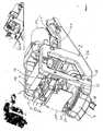
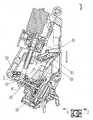
- Fig. 1shows an overview of an extraction module of the present invention.
- the extraction module for a capsule 24can be integrated in different beverage production devices, especially coffee brewing devices. It constitutes an independent module which only needs to be connected to a supply for electricity and for pressurised water (supplied e.g. from a pump connected to a thermoblock or boiler).
- the elements of the extraction moduleare fixed to a main frame 26.
- the main frame 26is composed of a left frame 1, a right frame 2, a lever axis 3, a upper frame 4, a rear frame 5 and a lower frame 6.
- the electrical motor 12drives a mechanical transmission comprising levers 19 in order to move a first jaw, i.e. a mobile brewing head support 7 carrying the upper brewer head 8 relative to a second jaw, i.e. the lower frame 6 which (in contrast to the mobile brewing head support 7) is fixed in translation to the main frame 26 and carries a lower brewing head 9 (see Figure 2 ) which is adapted to support the capsule 24.
- a first jawi.e. a mobile brewing head support 7 carrying the upper brewer head 8 relative to a second jaw, i.e. the lower frame 6 which (in contrast to the mobile brewing head support 7) is fixed in translation to the main frame 26 and carries a lower brewing head 9 (see Figure 2 ) which is adapted to support the capsule 24.
- the upper brewing head 8presents at its lower side means to inject a liquid, such as for example hot pressurised water, into the capsule 24.
- a liquidsuch as for example hot pressurised water
- the introduced liquidwill then interact with the beverage or liquid comestible ingredients contained in the capsule 24.
- the inventionencompasses all kinds of possible interactions, such as for example mixing, brewing, extracting or dissolving.
- the beverage or liquid comestiblebeing the result of the interaction of the introduced liquid and the ingredients contained in the capsule 27 can then be drained from the capsule 24 using draining means 27 connected to the lower frame 6.
- the lower frame 6 together with its lower brewing head 9constitutes a second jaw member which cooperates with the mobile brewing head support 7 and its upper brewing head 8, which together constitute a second jaw member.
- the two jaw members 6, 7can be moved relative to each other, wherein in the opened position as for example shown in Fig. 1 a capsule 24 can be inserted into the space confined by the two (distanced) jaw members 6, 7.
- the electrical motor 12can drive the upper brewing head 8 to move downwards until it reaches a closed position (which will be explained later on referring to Fig. 4 ), in which closed position the two jaw members 6, 7 tightly confine the inserted capsule 24.
- the beverage production processtakes place during the closed state of the extraction module shown in Fig. 4 .
- the replacement of a used capsule 24 by a new onetakes place when the extraction module has returned in its opened position as shown in Figure 1 .
- the rotary drive action of the motor 12is converted into a linear relative movement of the two jaw members 6, 7.
- the upper brewing head 8is guided 28 along a rectilinear column 29 being part of the main frame 26. (Actually respectively one guiding member 28 and vertical column 29 of the left frame 1 and the right frame 2, respectively, is provided at each side of the mobile brewing head support 7.)
- the motor 12is rotatably mounted to the main frame 26 at a motor block bearing axis 41.
- the sliding door 11If ever the lower edge 30 of the sliding door 11 encounters an obstacle during its downward movement, the sliding door 11 is pushed upwards against the biasing action of a spring 31 (s. Fig. 2 ) such that the sliding door 11 will activate the security switch 10 which will either cause the downward movement to be stopped or which will cause the rotation direction of the electrical motor 12 to be inverted such that the upper jaw with the sliding door 11 will eventually move upwards.
- a spring 31s. Fig. 2
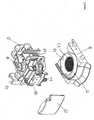
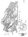
- Fig. 2shows parts of the extraction module of Fig. 1 , i.e. the security system comprising the sliding door 11, the spring 31 and the security switch 10. Further on, Fig. 2 shows in an exploded view the mobile brewing head support 7 carrying the upper brewing head 8. In Fig. 2 the two linear guiding means 28 can be seen which guide the mobile brewing head support 7 along the two co-parallel columns 29 of the main frame 26 (s. Fig. 1 ).
- FIG. 2shows a detailed view of the lower frame 6 with the lower brewing head 9.
- the lower brewing head 9comprises perforation means 32 which serve to open the lower face of the capsule 24 when the lower face of the capsule 24 is pressed against the perforation means 32.
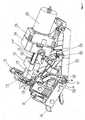
- the electric motor 12is connected to a gear box 13 fixed to a motor block support 16.
- the gear box 14drives a spindle 15, which cooperates with a shaft having two shaft guidances 18.
- the shaft 16is provided with an inner thread such that the rotational drive of the spindle 15 is converted into a translational displacement ⁇ x of the shaft 16.
- the shaft 16is connected to a lever arrangement being comprised of four levers 19 which are mounted in a knee-joint arrangement.
- the lever arrangementcomprises two coparallel pairs of levers, wherein the shaft 16 displaces translationally (s. ⁇ x) the knee joint (connection joint) 46 of each pair of levers 19.
- the upper free end of the upper lever of each pair of leversis free in rotation, but fixed in translation connected to the main frame 26 by means of a lever axis 3 (s. Fig. 1 ).
- each pair of levers 19is free in rotation, but fixed in translation to the main frame 26 (s. fig. 1 ), the lower free end of the opposed lever 19 of each pair of levers will be moved linearly downwards when, driven by the motor 12, the shaft 16 is pushing the connection point of each pair of levers 19, to the left side in Fig. 3 .
- the displacement of the shaft 16thereby is directed perpendicularly to the displacement of the free end of the lower free end of each pair of levers 19 and thus to the displacement of the mobile brewing head support 7.
- each pair of leversforms an acute angle when seen from the connection or knee-joint 46 connected to the shaft 16. Therefore, starting from the position as shown in Fig. 3 a relatively small displacement ⁇ x of the shaft 16 will result in a relatively large displacement ⁇ y of the mobile brewing head support 7.
- the mobile brewing head support 7will descend relatively fast but with relatively low force.
- each pair of leverscan actually be aligned, i.e. they form an obtuse angle of up to 180°.
- the closure forcei.e. the force with which the mobile brewing head support 7 will approach the lower frame 6 in the final phase and eventually abut against it, is much higher in this final phase of the approaching closing movement when compared to the initial stage as shown in Fig. 3 .
- the lever arrangement 19represents one example of a mechanical transmission means with varying transmission ratio during the course of the closing/opening movement.
- the closure forceis relatively low (and the closure speed relatively high).
- the mechanical transmission meansare designed such that the final stage of the closure movement, and particularly when the mobile brewing head support 7 presses against the lower frame 6.
- the electrical motor 12can be dimensioned relatively small as its torque is transmitted by mechanical transmission means (lever arrangement 19) into a closure force which is increasing with the course of the closure transfer movement.
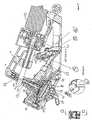
- a lower capsule detaching unit (capsule ejector) 20is shown in Fig. 3 , 4 and 5 .
- the main elements of the capsule ejector 20are essentially annular ejecting member 34 as well as an ejector control arm 35 having at its inner side (not shown in the figures) for example pins 20a engaging with inclined ramp 7b of the mobile brewing head support 7.
- Fig. 6shows a cross sectional view in the extraction module according to the present invention is in its open state.
- a useris about to insert the capsule 24.
- the lower capsule ejector 20is in a position where the outer rim portion of the capsule 24 will sandwich the annular member 34 of the lower capsule ejector 20 with regard to the lower frame 6.
- a detaching action with regard to the mobile brewing head support 7is mechanically and actively coupled to the main movement of the mobile brewing head support 7.
- an upper capsule ejector 25is provided in order to detach the capsule from the mobile brewing head support 7, and especially in order to detach the capsule from water injection means 36 housed in a concave portion of the mobile brewing head support 7.
- this upper capsule ejector 25is in an retracted position.
- the upper capsule ejector 25is moveable between the retracted position as shown in Fig. 6 and an advanced position which will be explained later on (s. for example Fig. 8 ).
- the movement of the upper capsule ejector 25is actively controlled by the interaction of the upper end of the upper capsule ejector 25 with a control cam 37 which is fixed in translation to the shaft 16. Therefore, the current relative position of the upper capsule ejector 25 vis-à-vis the mobile brewing head support 7, e.g. in the retracted or advanced position, depends on the current position of the shaft 16 (driven by the spindle 15) and the particularly designed shape the control cam 37.
- Fig. 6also the security system comprising the spring-biased sliding door 11 and the security switch 10 can be seen.
- a capsule holder 21is depicted in Fig. 6 , which can carry out a rotational movement, which is controlled by the interaction of a steering axis 22 and a spring 23 with the mobile brewing head support 7 which will be explained in detail later on.
- the capsule holder 21is provided with a stop wall 39.
- the stop wall 39extends beyond the reception claim of the lower brewing head 9 of the lower frame 6. Therefore, when the user is inserting a capsule 24 as shown in Fig. 6 , this insertion is facilitated by having the stop wall 39 protruding upwards from this reception plane.
- the perforation means 32have already open the lower surface of the capsule 24 and a produced beverage can be collected and drained through the draining channel 27.
- Fig. 7From Fig. 7 can also be seen that in this closed position of the extraction module the upper capsule ejector 25 is in its most retracted position. This retracted position is controlled by the control cam 37 provided at the end of the shaft 16.
- a comparison of figures 6 and 7shows that the motor 12, the gear box 13, the motor block support 14, the spindle 15 and the shaft 16 are not fixedly mounted to the main frame 26, but are allowed to carry out a swivel movement during a closure and opening transfer movement, respectively, of the jaw members 6, 7.
- the mentioned motor block parts(the motor 12, the gear box 13, the motor block support 14, the spindle 15 and the shaft 16) are actually fixed free in rotation to the main frame 26 by the motor block bearing axis 41 (see e.g. Figure 3 ).
- This rearward displacement of the capsule 24is promoted by the fact that the extraction module is preferably mounted in the beverage production device such that it is inclined rearward by an angle of e.g. 30°.
- the rear portion of the lower brewing head 9is positioned lower than the front portion thereof.
- the control cam 37 of the shaft 16will cause a relative protruding movement of the upper capsule ejector 25 vis-à-vis the water injection means of the upper brewing head 8.
- This detaching action of the upper capsule ejector 25 vis-à-vis the upper brewing head 8occurs before the annular member 34 of the lower capsule ejector 20 will lift the capsule 24 from the lower frame 6 in a rotational movement.
- This delay of the detaching action of the upper capsule ejector 25 and the lower capsule ejector 20, respectively,is defined by the corresponding designs of the control cam 37 of the shaft 16 and the bent control arm of the lower capsule ejector.
- a upper cam 44 of the steering axisis rotated clockwise by a recession 45 of the mobile brewing head support 7 such that the blocking effect of the steering axis 22 ceases and the capsule holder 22 can resume its upper position shown in Figure 6 , in which the stop wall 39 defines a rear stop when inserting the next capsule 24.
- the motor 12drives the opening/closure movement of the extraction module. Coupled to this main action is the delayed action of the detaching means for the upper jaw and the lower jaw, respectively. Finally, also the driving of the displacements of the capsule holder 21 are mechanically coupled to said main action.
Landscapes
- Engineering & Computer Science (AREA)
- Mechanical Engineering (AREA)
- Food Science & Technology (AREA)
- Apparatus For Making Beverages (AREA)
- Toys (AREA)
Abstract
Description
- The present invention generally relates to the production of a beverage or a liquid comestible on the basis of a capsule, which capsule contains ingredients which are able to produce a beverage or liquid comestible when interacting with a liquid, such as for example hot pressurised water, introduced into the volume of the capsule.
- Especially in the field of coffee machines, machines have been widely developed in which an initially hermetically sealed capsule containing beverage ingredients is inserted (while still being sealed) in an opened extraction module. Then the extraction module surrounding the capsule is tightly closed, water is injected at the first face of the capsule, the beverage is produced in the volume of the capsule and a produced beverage can be drained from a second face of the capsule.
- Once the beverage production process is finished, the used capsule has to be removed from the extraction module.
- Different approaches are known for facilitating the handling of such capsule-based beverage production machines.
EP 1 095 605 A1 teaches an ejection mechanism for such a capsule, wherein when opening the extraction module, automatically an ejector device, mechanically coupled to the opening movement, lifts the used capsule off its support.WO 2005/058111 A1 discloses a device for producing a beverage from a capsule with an automatic operating cycle. The device comprises filter holding means and a dispensing unit which engage with each other in order to dispense a coffee infusion. Thereby, mechanical conversion means are provided for transmitting a drive action of a motor into a relative displacement of the holding means and the dispensing unit.- In order to inject the liquid into the capsule, often needle-like elements are used which perforate the capsule from outside. Once the water injection and beverage production process is finished, the capsule tends to stay attached to these injection means. To overcome this problem,
EP 1 444 932 A1 - In view of the above it is the object of the present invention to propose a technique for a reliable and simple mechanical arrangement.
- This object is achieved by means of the features of the independent claims. The dependent claims develop further the central idea of the present invention.
- A first aspect of the present invention relates to a device for producing a beverage from a capsule, the device comprising
- an extraction module which comprises a first jaw member and a cooperating second jaw member.
- In an opened state of the extraction module the jaw members are distanced from each other. In the closed state the jaw members tightly enclose a capsule space.The device further comprises a motorwhich drives the transfer of the extraction module between the closed and opened state.Thereby, mechanical conversion means transmit the drive action of the motor into a relative displacement of the jaw members and have a variable transmission ratio converting the drive action of the motor into a closure force, i.e. a force with which the first and second jaw member are approaching each other. The closure force increases during the course of the closure movement. Thus the closure force reaches its maximum when it is needed most, i.e. when the jaw members have to enclose tightly any inserted capsule.
- Further, the mechanical conversion means of the device comprise a lever arrangement. Thereby, the lever is connected to a spindle driven by the motor.
- The rotational drive of the motor can be converted into a translational drive by having the spindle interact with a thread of a drive shaft.
- The lever.arrangement can be composed of two co-parallel pairs of levers. The levers of each pair of levers can be respectively connected to each other by a knee joint (46). The motor can actuate directly or indirectly on the knee joint (46).
- In the opened state of the extraction module each pair of levers can form an acute angle extending from the knee joint (46). In the closed state of the extraction module each pair of levers can form an obtuse angle extending from the knee joint (46).
- The extremity of one lever of each pair of levers opposite to the knee joint can be respectively connected to one of the jaw members. The other extremity can be respectively fixed in translation.
- The position and/or orientation of the motor can follow the transfer movement of the extraction module between the opened and the closed state.
- Jaw member guiding means can be provided such that the jaw members are displacable along aligned trajectories when transferring the extraction module between its closed and opened state.
- The device can comprise a frame for mounting the extraction module and the motor to a main part of the beverage production device.
- One of the jaw members can comprise means for injecting a liquid into an inserted capsule. The respectively other jaw member can comprise means for draining a produced beverage from an inserted capsule.
- The device can comprise means for actively detaching the capsule from the injection means. Thereby the detaching means can be functionally coupled to the motor-driven transfer movement of the extraction module from its closed state towards its opened state.
- A further aspect of the invention relates to a device for producing a beverage from a capsule containing a beverage ingredient. The device comprises an extraction module having a first jaw member and a cooperating second jaw member. In an opened state of the extraction module the jaw members are distanced from each other while in the closed state the jaw members tightly enclose a capsule space.
- A motor drives the transfer of the extraction module between the closed and opened state.
- First capsule detaching means are provided for actively detaching the capsule from the first jaw member, and second capsule detaching means are provided for actively detaching the capsule from the second jaw member. Thereby the first and second detaching means can be functionally coupled to the motor-driven transfer movement of the extraction module.
- The first and second detaching means can be mechanically coupled with a transfer movement of the extraction module from the closed state to the opened state such that one of the first and second detaching means is activated at a defined time after the activation of the respectively other detaching means.
- At least one of the detaching means can be designed to carry out a rotational detaching movement.
- A still further aspect of the present invention relates to a device for producing a beverage from a capsule (24), comprising a security sensor which enables the driving activity of the motor from the opened state to the closed state only as long as no obstacle is sensed in a space confined by the two approaching jaw members.
- A still further aspect of the present invention relates to a method for operating a capsule-based beverage production system. Thereby an extraction module is transferred, driven by a motor, from an opened state, in which the capsule is inserted, to a closed state in which the extraction module tightly encloses the inserted capsule. The extraction module comprises first jaw member and a cooperating second jaw member. The driving action of the motor is mechanically converted into a closure force, i.e. a force with which the jaw members approach each other, which is increasing with the course of the closure movement.
- A still further aspect of the present invention relates to a method for operating a capsule-based beverage production system, wherein an extraction module is transferred from a closed state, in which a beverage is produced from the inserted capsule while being tightly enclosed by the extraction module, to an opened state, the extraction module comprising a first jaw member and a cooperating second jaw member. Thereby the capsule (24) is actively detached from the both jaw members when the extraction module is transferred from its closed state to its opened state.
- The capsule can be detached in a curved trajectory from at least one of the jaw members.
- Further advantages, features and objects of the present invention will become evident from the following detailed description of an embodiment of the present invention when taking in conjunction with the figures of the enclosed drawings.
Fig. 1 shows an extraction module for a beverage production device according to the present invention,Fig. 2 shows components of the extraction module,Fig. 3 shows a partial view of the extraction module in an open state,Fig. 4 shows a partial view an extraction module according to the present invention when the extraction module is in its closed state.Fig. 5 shows an extraction module according to the present invention during its transfer movement from its close state to its open state,Fig. 6 shows a cross sectional view of a extraction module in the open state comparable toFig. 3 ,Fig. 7 shows a cross sectional view of an extraction module of the present invention in its closed state essentially corresponding toFig. 4 ,Fig. 8 shows a cross sectional view of the extraction module according to the present invention during its transfer movement from its close state to the open state, such thatFig. 8 is essentially corresponding toFig. 5 , andFig. 9 shows a cross-sectional view of the extraction module when in its opened state.- Before referring in detail to the figures of the enclosed drawings, a few terms will be explained:
- "Beverage" encompasses both drinkable liquids and liquid comestibles such as e.g. soups.
- A"capsule" is any closed receptacle which is able to contain a beverage ingredient in dry, liquid, solid or other form. The capsule can have a hard shell or a soft shell. It can be made from a single material or of a mix of materials. It can have all kinds of shapes, such as e.g. a pad or a cup-like shape. It can be hermetically sealed or not.
- The term"extraction" and"extraction module" has been used as it is usually used when referring to the production of a coffee beverage. It is to be understood that this term refers to all kind of interactions between a liquid and an ingredient, such as e.g. mixing, dissolving, brewing etc.
Fig. 1 shows an overview of an extraction module of the present invention.- The extraction module for a
capsule 24 can be integrated in different beverage production devices, especially coffee brewing devices. It constitutes an independent module which only needs to be connected to a supply for electricity and for pressurised water (supplied e.g. from a pump connected to a thermoblock or boiler). - As can be seen from
Figure 1 , the front part of the main frame can be raised relative to the horizontal rear part by an angle between 20° and 40°, preferably 30° to the horizontal plane. Thus thecapsule 24 will be received in the extraction module in a rearwards-inclined position, such that the insertion movement of acapsule 24 will be directed ergonomically slightly downwards. As will be explained later on, this rearward inclination of thecapsule 24 in the extraction module also promotes the removal of a usedcapsule 24 to the rear of the extraction module. - The elements of the extraction module are fixed to a
main frame 26. Themain frame 26 is composed of aleft frame 1, aright frame 2, a lever axis 3, a upper frame 4, a rear frame 5 and alower frame 6. - Generally, the extraction module is driven by an
electrical motor 12 controlled by an electronic control unit (not shown in the drawings). Note that the electronic control unit is also connected to the safety system such that it can control themotor 12 depending on an output detection signal from the safety system. - The
electrical motor 12 drives a mechanicaltransmission comprising levers 19 in order to move a first jaw, i.e. a mobilebrewing head support 7 carrying theupper brewer head 8 relative to a second jaw, i.e. thelower frame 6 which (in contrast to the mobile brewing head support 7) is fixed in translation to themain frame 26 and carries a lower brewing head 9 (seeFigure 2 ) which is adapted to support thecapsule 24. - The
upper brewing head 8 presents at its lower side means to inject a liquid, such as for example hot pressurised water, into thecapsule 24. The introduced liquid will then interact with the beverage or liquid comestible ingredients contained in thecapsule 24. The invention encompasses all kinds of possible interactions, such as for example mixing, brewing, extracting or dissolving. - The beverage or liquid comestible being the result of the interaction of the introduced liquid and the ingredients contained in the
capsule 27 can then be drained from thecapsule 24 using draining means 27 connected to thelower frame 6. - The
lower frame 6 together with its lower brewing head 9 constitutes a second jaw member which cooperates with the mobilebrewing head support 7 and itsupper brewing head 8, which together constitute a second jaw member. - Thus, the two
jaw members Fig. 1 acapsule 24 can be inserted into the space confined by the two (distanced)jaw members - Starting from the opened position as shown in
Fig. 1 , theelectrical motor 12 can drive theupper brewing head 8 to move downwards until it reaches a closed position (which will be explained later on referring toFig. 4 ), in which closed position the twojaw members capsule 24. The beverage production process takes place during the closed state of the extraction module shown inFig. 4 . The replacement of a usedcapsule 24 by a new one takes place when the extraction module has returned in its opened position as shown inFigure 1 . - The rotary drive action of the
motor 12 is converted into a linear relative movement of the twojaw members Fig. 1 , theupper brewing head 8 is guided 28 along arectilinear column 29 being part of themain frame 26. (Actually respectively one guidingmember 28 andvertical column 29 of theleft frame 1 and theright frame 2, respectively, is provided at each side of the mobilebrewing head support 7.) - The
motor 12 is rotatably mounted to themain frame 26 at a motorblock bearing axis 41. - As will be explained later on, particularly in the final approaching phase of the closure movement, the closure force, i.e. the force with which the upper and the lower jaw are approaching each other, is designed to be very high. In order to prevent both injuries of a user manipulating the extraction module and/or a damaging of parts of the shown extraction module, a security system is provided comprising a sliding
door 11 and a security switch 10 (shown inFig. 2 ). - If ever the
lower edge 30 of the slidingdoor 11 encounters an obstacle during its downward movement, the slidingdoor 11 is pushed upwards against the biasing action of a spring 31 (s.Fig. 2 ) such that the slidingdoor 11 will activate thesecurity switch 10 which will either cause the downward movement to be stopped or which will cause the rotation direction of theelectrical motor 12 to be inverted such that the upper jaw with the slidingdoor 11 will eventually move upwards. Fig. 2 shows parts of the extraction module ofFig. 1 , i.e. the security system comprising the slidingdoor 11, the spring 31 and thesecurity switch 10. Further on,Fig. 2 shows in an exploded view the mobilebrewing head support 7 carrying theupper brewing head 8. InFig. 2 the two linear guiding means 28 can be seen which guide the mobilebrewing head support 7 along the twoco-parallel columns 29 of the main frame 26 (s.Fig. 1 ).- Finally,
Fig. 2 shows a detailed view of thelower frame 6 with the lower brewing head 9. - The lower brewing head 9 comprises perforation means 32 which serve to open the lower face of the
capsule 24 when the lower face of thecapsule 24 is pressed against the perforation means 32. - In the shown example (s.
Fig. 1 ) the capsule has the shape of a pad. Correspondingly, the lower brewing head 9 is provided with afrustroconical recess 33 centering the magic matching contour of thecapsule 24. A produced beverage is collected in therecess 33 and then guided to the guidingchannel 27 underneath. Fig. 3 shows the enclosing unit according to the present invention without themain frame 26 in order to have a better view of the static and moveable parts housed inside and mounted to themain frame 26.Fig. 3 shows the enclosing unit in its opened state. This can be seen from the fact that theupper brewing unit 7 is distanced from thelower frame 6 and from the upper face of acapsule 24 placed by a user on thelower frame 6.- The
electric motor 12 is connected to agear box 13 fixed to amotor block support 16. - The
gear box 14 drives aspindle 15, which cooperates with a shaft having twoshaft guidances 18. Theshaft 16 is provided with an inner thread such that the rotational drive of thespindle 15 is converted into a translational displacement Δx of theshaft 16. - The
shaft 16 is connected to a lever arrangement being comprised of fourlevers 19 which are mounted in a knee-joint arrangement. - The lever arrangement comprises two coparallel pairs of levers, wherein the
shaft 16 displaces translationally (s. Δx) the knee joint (connection joint) 46 of each pair oflevers 19. - The upper free end of the upper lever of each pair of levers is free in rotation, but fixed in translation connected to the
main frame 26 by means of a lever axis 3 (s.Fig. 1 ). - Therefore, as the upper free end of each pair of
levers 19 is free in rotation, but fixed in translation to the main frame 26 (s.fig. 1 ), the lower free end of the opposedlever 19 of each pair of levers will be moved linearly downwards when, driven by themotor 12, theshaft 16 is pushing the connection point of each pair oflevers 19, to the left side inFig. 3 . - The displacement of the
shaft 16 thereby is directed perpendicularly to the displacement of the free end of the lower free end of each pair oflevers 19 and thus to the displacement of the mobilebrewing head support 7. - The lower free end of each pair of
levers 19 is rotatably connected to the mobilebrewing head support 7. - As a result, the rotational drive of the
spindle 15 will be converted into a translational displacement of theshaft 16, which in turn is converted into a perpendicular displacement of the mobilebrewing head support 7, which is referenced as Δy inFig. 3 . - In the opened position as shown in
Fig. 3 , each pair of levers forms an acute angle when seen from the connection or knee-joint 46 connected to theshaft 16. Therefore, starting from the position as shown inFig. 3 a relatively small displacement Δx of theshaft 16 will result in a relatively large displacement Δy of the mobilebrewing head support 7. Correspondingly, in this early stage of a closure movement, i.e. a transfer movement to lower the mobilebrewing head support 7, the mobilebrewing head support 7 will descend relatively fast but with relatively low force. - The more the mobile
brewing head support 7 is driven downwards, the more the initially acute angle of each of thepairs 19 will be converted into an obtuse angle. At the end of the closure transfer movement (s.Fig. 4 ) each pair of levers can actually be aligned, i.e. they form an obtuse angle of up to 180°. - Therefore, at the end of the approaching transfer movement, i.e. when the mobile
brewing head support 7 is about to abut against thelower frame 6, the same incremental displacement Δx of theshaft 16 will be converted in a much smaller relative displacement Δy of the mobile brewing head support 7 (when compared to the initial position as shown inFig. 3 ). On the other hand, the closure force, i.e. the force with which the mobilebrewing head support 7 will approach thelower frame 6 in the final phase and eventually abut against it, is much higher in this final phase of the approaching closing movement when compared to the initial stage as shown inFig. 3 . - Therefore, the
lever arrangement 19 represents one example of a mechanical transmission means with varying transmission ratio during the course of the closing/opening movement. In the early stage of the closing movement (starting from the open state of the extraction module) the closure force is relatively low (and the closure speed relatively high). On the other hand, the mechanical transmission means are designed such that the final stage of the closure movement, and particularly when the mobilebrewing head support 7 presses against thelower frame 6. - Note that the function of a
capsule holder 21 cooperating with a steeringaxis 22 will be explained later on. Fig. 4 shows a broken view when the closing system is in its closed position in which the mobilebrewing head support 7 and thelower frame 6 tightly enclose a capsule confinement space.- As can be seen from
Fig. 4 , themotor 12 has driven thespindle 15 such that theshaft 16 is at its most advanced position (to the left inFig. 4 ) and the pairs oflevers 19 do no longer form an acute angle, but an angle of approx. 180°. In this closed state of the extraction module a relatively low force driven from themotor 12 will cause a very high down-force of the respectivelylower lever 19 of each pairs oflevers 19. - In the position as shown in
Fig. 4 , the beverage production process takes place. Once the beverage production process has been completed, the electronic control (not shown in the figures) will control theelectric motor 12 to turn in the reverse direction, such that thespindle 15 will retract theshaft 16 such that in turn the mobilebrewing head support 7 will be lifted back to the position as shown inFig. 3 . - From the above explanations and
Figures 3 and4 it is clear that theelectrical motor 12 can be dimensioned relatively small as its torque is transmitted by mechanical transmission means (lever arrangement 19) into a closure force which is increasing with the course of the closure transfer movement. - In the following it will be explained that other movements are mechanically coupled to this main closure/opening movement of the extraction module.
- In
Fig. 3 ,4 and5 a lower capsule detaching unit (capsule ejector) 20 is shown. As can be seen particularly fromFig. 5 , the main elements of thecapsule ejector 20 are essentially annular ejectingmember 34 as well as anejector control arm 35 having at its inner side (not shown in the figures) forexample pins 20a engaging withinclined ramp 7b of the mobilebrewing head support 7. - Starting from
Fig. 3 , when the mobilebrewing head support 7 is moved linearly downwards, the extremity of thecontrol arm 35 having aninner pin 20a will slide over theramp 7a until the free extremity of thecontrol arm 35 will be placed at the most inner position of theinclined ramp 7a when the extraction module reaches its closed state as shown inFig. 4 . - On the other hand, when a capsule is inserted into the capsule insertion space between the
lower frame 6 and the mobilebrewing head support 7, theannular element 34 of thelower capsule ejector 20 is sandwiched between the rim portion of thecapsule 24 and thelower frame 6. - Now, when having finished the beverage production process the mobile
brewing head support 7 is again lifted upwards (starting from the closed state as shown inFig. 4 towards the open intermediate state ofFig. 5 ), the engagement pins 20a attached to the inner side of thecontrol arm 35 will become engaged with theinclined ramp 7b such that thebent control arm 35 will turn around a bearing axis. This in turn will cause to rotate theannular member 34 of thecapsule ejector 20 from the position as shown inFig. 4 in which it rests on the upper surface of thelower frame 6, to a rotate position as shown inFig. 5 . At the same time theannular member 34 will engage with the outer rim of the capsule 24 (s.Fig. 5 ) and detach in a rotational movement thecapsule 24 from the recession of the lower brewing head 9. - As will be explained later on, this rotational movement of the
lower capsule ejector 20 will cause to slide the (used)capsule 24 backwards into a tray (not shown in the drawings). - Due to the engagement of the
bent control arm 35 of thelower capsule ejector 20 and theramp 7b of the mobilebrewing head support 7 this detachment action lifting thecapsule 24 from thelower frame 6 is actively controlled by a mechanical coupling to the opening transfer movement of the mobilebrewing head support 7. - Further features of the invention will now be explained referring to the cross sectional view of
figures 6 to 8 . Fig. 6 shows a cross sectional view in the extraction module according to the present invention is in its open state.- A user is about to insert the
capsule 24. - The
lower capsule ejector 20 is in a position where the outer rim portion of thecapsule 24 will sandwich theannular member 34 of thelower capsule ejector 20 with regard to thelower frame 6. - As will be explained in the following, also a detaching action with regard to the mobile
brewing head support 7 is mechanically and actively coupled to the main movement of the mobilebrewing head support 7. In order to detach the capsule from the mobilebrewing head support 7, and especially in order to detach the capsule from water injection means 36 housed in a concave portion of the mobilebrewing head support 7, anupper capsule ejector 25 is provided. In the position as shown inFig. 6 thisupper capsule ejector 25 is in an retracted position. Generally, theupper capsule ejector 25 is moveable between the retracted position as shown inFig. 6 and an advanced position which will be explained later on (s. for exampleFig. 8 ). The movement of theupper capsule ejector 25 is actively controlled by the interaction of the upper end of theupper capsule ejector 25 with a control cam 37 which is fixed in translation to theshaft 16. Therefore, the current relative position of theupper capsule ejector 25 vis-à-vis the mobilebrewing head support 7, e.g. in the retracted or advanced position, depends on the current position of the shaft 16 (driven by the spindle 15) and the particularly designed shape the control cam 37. - In
Fig. 6 also the security system comprising the spring-biased slidingdoor 11 and thesecurity switch 10 can be seen. - Furthermore, a
capsule holder 21 is depicted inFig. 6 , which can carry out a rotational movement, which is controlled by the interaction of a steeringaxis 22 and aspring 23 with the mobilebrewing head support 7 which will be explained in detail later on. - In any case, the
capsule holder 21 is provided with astop wall 39. In the position as shown inFig. 6 thestop wall 39 extends beyond the reception claim of the lower brewing head 9 of thelower frame 6. Therefore, when the user is inserting acapsule 24 as shown inFig. 6 , this insertion is facilitated by having thestop wall 39 protruding upwards from this reception plane. - When the
motor 12 drives the mobilebrewing head support 7 into the closed position as shown inFig. 7 , the water injection means 38 are pushed inside the upper surface of thecapsule 24. In this position as shown inFig. 7 water under pressure can enter thecapsule 24 and the interaction with the beverage ingredients contained in thecapsule 24 can commence. - At the same time, the perforation means 32 have already open the lower surface of the
capsule 24 and a produced beverage can be collected and drained through the drainingchannel 27. - From
Fig. 7 can also be seen that in this closed position of the extraction module theupper capsule ejector 25 is in its most retracted position. This retracted position is controlled by the control cam 37 provided at the end of theshaft 16. - When the mobile
brewing head support 7 is transferred from the open position as shown inFig. 6 to the closed position as shown inFig. 7 , the initiallyupstanding stop wall 39 of thecapsule holder 21 will be pushed downwards by the mobilebrewing head support 7. When thecapsule holder 21 having thestop wall 39 is rotated (counter-clockwise in the drawings), aspring 23 will be tensioned. The tensionedspring 23 causes the steeringaxis 22 to rotate counter-clockwise, such that a downwards extending stopper arm 42 of the steeringaxis 22 will be rotated on top of an upstanding stop 43 of thecapsule holder 21. As a result, thecapsule holder 21 is blocked in its lower position shown inFigure 7 due to the blocking effect of the stopper arm 42 and the stop 43. - A comparison of
figures 6 and7 shows that themotor 12, thegear box 13, themotor block support 14, thespindle 15 and theshaft 16 are not fixedly mounted to themain frame 26, but are allowed to carry out a swivel movement during a closure and opening transfer movement, respectively, of thejaw members - The mentioned motor block parts (the
motor 12, thegear box 13, themotor block support 14, thespindle 15 and the shaft 16) are actually fixed free in rotation to themain frame 26 by the motor block bearing axis 41 (see e.g.Figure 3 ). - When, starting from the closed beverage production state as shown in
Fig. 7 , the mobilebrewing head support 7, driven by themotor 12 is moved upwards again, thecapsule holder 21 will not immediately follow this movement due to an interaction of thecapsule holder 21 with the steeringaxis 22. - This delay of the rotation of the
capsule holder 21 makes it possible that thelower capsule ejector 22 lifts, as shown infigure 9 , in a rotational movement thecapsule 24 from its recessed position, such that thecapsule 24 will eventually (as shown inFig. 9 ) slide from the inclinedlower capsule ejector 20 over a slidingsurface 40 of thecapsule holder 21 and backwards into a tray (not shown). - This rearward displacement of the
capsule 24 is promoted by the fact that the extraction module is preferably mounted in the beverage production device such that it is inclined rearward by an angle of e.g. 30°. Thus the rear portion of the lower brewing head 9 is positioned lower than the front portion thereof. - During the opening movement, i.e. the upwards movement of the mobile
brewing head support 7, the control cam 37 of theshaft 16 will cause a relative protruding movement of theupper capsule ejector 25 vis-à-vis the water injection means of theupper brewing head 8. This detaching action of theupper capsule ejector 25 vis-à-vis theupper brewing head 8 occurs before theannular member 34 of thelower capsule ejector 20 will lift thecapsule 24 from thelower frame 6 in a rotational movement. - This delay of the detaching action of the
upper capsule ejector 25 and thelower capsule ejector 20, respectively, is defined by the corresponding designs of the control cam 37 of theshaft 16 and the bent control arm of the lower capsule ejector. - As can be seen from
Figure 8 , when theshaft 16 is retracted by themotor 12 starting from the closed position as shown inFigure 7 , theupper capsule ejector 25 is held in position by a first section 37b of the control cam 37, while theupper brewing head 8 is already moving upwards. This corresponds to a relative protrusion movement of the upper capsule ejector vis-à-vis theupper brewing head 8 such that thecapsule 24 will be actively detached from the perforation and injection means 32. - Only when the
shaft 16 is retracted to an extent that theupper capsule ejector 25 start cooperating with a second, recessed section 37b of the control cam 37, theuppercapsule ejector 25 is free to follow the upwards movement of theupper brewing head 8. - In the state du ring the opening (upwards) movement of the
upper brewing head 6 shown inFigure 8 is still blocked in its lower position. - However, when the upwards opening movement reaches the position shown in
Figure 9 , aupper cam 44 of the steering axis is rotated clockwise by arecession 45 of the mobilebrewing head support 7 such that the blocking effect of the steeringaxis 22 ceases and thecapsule holder 22 can resume its upper position shown inFigure 6 , in which thestop wall 39 defines a rear stop when inserting thenext capsule 24. - To summarise, as a main action the
motor 12 drives the opening/closure movement of the extraction module. Coupled to this main action is the delayed action of the detaching means for the upper jaw and the lower jaw, respectively. Finally, also the driving of the displacements of thecapsule holder 21 are mechanically coupled to said main action. - 1
- left frame
- 2
- right frame
- 3
- lever axis
- 4
- upper frame
- 5
- rear frame
- 6
- lower frame
- 7
- mobile brewing head support
- 7a
- ramp
- 8
- upper brewing head
- 9
- lower brewing head
- 10
- security switch
- 11
- security door
- 12
- motor
- 13
- gearbox
- 14
- motor block support
- 15
- spindle
- 16
- shaft
- 17
- shaft guidance
- 18
- shaft guidance
- 19
- lever
- 20
- Capsule ejector
- 20a
- pins
- 21
- capsule holder
- 22
- steering axis
- 23
- steering axis spring
- 24
- capsule
- 25
- central capsule ejector
- 26
- main frame
- 27
- draining channel
- 28
- guiding means
- 29
- column of the main frame
- 30
- lower edge of the sliding door
- 31
- spring of the security system
- 32
- perforation means
- 33
- frustroconical recess of the lower brewing head
- 34
- annular ejecting member
- 35
- bent lower ejector control arm
- 36
- bearing axis
- 37
- control cam
- 38
- water injection means
- 39
- stop wall
- 40
- glide surface
- 41
- motor block bearing axis
- 42
- stopper arm
- 43
- upstanding stop
- 44
- upper cam
- 45
- recession
- 46
- knee joint
Claims (16)
- A device for producing a beverage from a capsule (24),comprising- an extraction module which comprises a first jaw member (6) and a cooperating second jaw member (7), wherein in an opened state of the extraction module the jaw members (6, 7) are distanced from each other while in the closed state the jaw members (6, 7) are in tight contact,- a motor (12) for controlling the transfer of the extraction module between the closed and opened state, and- mechanical conversion means (19) transmitting the drive action of the motor (12) into a relative displacement of the jaw members (6, 7), thereby having a variable transmission ratio which varies during the course of the transfer between the opened and the closed state of the extraction module,characterized in that
the mechanical conversion means (19) are designed such that they convert the drive action of the motor (12) into a closure force, i.e. a force with which the first and second jaw member (6, 7) are approaching each other, which closure force is increasing during the course of the closure movement, and
wherein the mechanical conversion means (19) further comprise a lever arrangement (19) which is connected to a threaded spindle (15) driven by the motor (12). - The device according to claim 1,
wherein the rotational drive of the motor converted into a translational drive by having the spindle (15) interact with a thread of a drive shaft (16). - The device according to any of claims 1 or 2,
wherein the lever arrangement (19) is composed of two co-parallel pairs of levers (19), the levers of each pair of levers (19) being respectively connected to each other by a knee joint (46), the motor actuating directly or indirectly on the knee joint (46). - The device according to claim 3,
wherein in the opened state of the extraction module each pair of levers (19) forms an acute angle extending from the knee joint (46), while in the closed state of the extraction module each pair of levers (19) forms an obtuse angle of up to 180° extending from the knee joint (46). - The device according to claim 2 or 3,
wherein the extremity of one lever (19) of each pair of levers opposite to the knee joint (46) is respectively connected to one of the jaw members (6, 7), while the other extremity is respectively fixed in translation. - The device according to any of the preceding claims,
wherein the position and/or orientation of the motor (12) follows the transfer movement of the extraction module between the opened and the closed state. - The device according to any of the preceding claims,
wherein jaw member guiding means (1, 2) are provided such that the jaw members (6, 7) are displacable along aligned trajectories when transferring the extraction module between its closed and opened state. - The device according to any of the preceding claims, comprising a frame (26) for mounting the extraction module and the motor (12) to a main part of the beverage production device.
- The device according to claim 8,
wherein a front part of the frame (26) is raised by an acute angle vis-à-vis a horizontal rear part of the frame. - The device according to any of the preceding claims,
wherein the capsule (24) is positioned in the extraction module in a rearwards-inclined position to the horizontal plane. - The device according to any of the preceding claims,
wherein one of the jaw members (6, 7) comprising means for injecting a liquid into an inserted capsule and the respectively other jaw member comprises means for draining a produced beverage from an inserted capsule (24). - The device according to claim 11, comprising means for actively detaching the capsule from the injection means, the detaching means being actively controlled by the motor-driven transfer movement of the extraction module from its closed state towards its opened state.
- The device according to any of the preceding claims, further comprising:- first capsule detaching means for actively detaching the capsule (24) from the first jaw member, and- second capsule detaching means for actively detaching the capsule (24) from the second jaw member, wherein the first and second detaching means are mechanically coupled with the motor-driven transfer movement of the extraction module.
- The device according to claim 13,
wherein the first and second detaching means are mechanically coupled with a transfer movement of the extraction module from the closed state to the opened state such that one of the first and second detaching means is activated at a defined time after the activation of the respectively other detaching means. - The device according to any of claims 13 or 14,
wherein at least one of the detaching means carries out a rotational detaching movement. - The device according to any of the preceding claims, further comprising:- a security sensor which enables the driving activity of the motor from the opened state to the closed state only as long as no obstacle is sensed in a space confined by the two approaching jaw members.
Priority Applications (14)
| Application Number | Priority Date | Filing Date | Title |
|---|---|---|---|
| ES05021062.4TES2317123T5 (en) | 2005-09-27 | 2005-09-27 | Extraction module for a beverage production device from capsules |
| PL05021062TPL1767129T3 (en) | 2005-09-27 | 2005-09-27 | Extraction module for a capsule-based beverage production device |
| EP05021062.4AEP1767129B2 (en) | 2005-09-27 | 2005-09-27 | Extraction module for a capsule-based beverage production device |
| PT05021062TPT1767129E (en) | 2005-09-27 | 2005-09-27 | Extraction module for a capsule-based beverage production device |
| DE602005010583TDE602005010583D1 (en) | 2005-09-27 | 2005-09-27 | Extraction module for a capsule-based beverage machine |
| DK05021062TDK1767129T3 (en) | 2005-09-27 | 2005-09-27 | Extraction module for a capsule based beverage making device |
| AT05021062TATE411757T2 (en) | 2005-09-27 | 2005-09-27 | EXTRACTION MODULE FOR A CAPSULE BASED BEVERAGE MACHINE |
| US11/534,036US8272319B2 (en) | 2005-09-27 | 2006-09-21 | Extraction module for a capsule-based beverage production device |
| JP2006260101AJP5193449B2 (en) | 2005-09-27 | 2006-09-26 | Extraction module for beverage production equipment with capsules |
| CN2006101393925ACN1939194B (en) | 2005-09-27 | 2006-09-27 | Device for producing drink from capsule |
| HK07105328.5AHK1099188B (en) | 2007-05-21 | Extraction module for a capsule-based beverage production device | |
| HR20080616THRP20080616T3 (en) | 2005-09-27 | 2008-11-26 | Extraction module for a capsule-based beverage production device |
| US13/597,707US8733229B2 (en) | 2005-09-27 | 2012-08-29 | Extraction module for a capsule-based beverage production device |
| JP2012219194AJP5558541B2 (en) | 2005-09-27 | 2012-10-01 | Extraction module for beverage production equipment with capsules |
Applications Claiming Priority (1)
| Application Number | Priority Date | Filing Date | Title |
|---|---|---|---|
| EP05021062.4AEP1767129B2 (en) | 2005-09-27 | 2005-09-27 | Extraction module for a capsule-based beverage production device |
Publications (3)
| Publication Number | Publication Date |
|---|---|
| EP1767129A1 EP1767129A1 (en) | 2007-03-28 |
| EP1767129B1 EP1767129B1 (en) | 2008-10-22 |
| EP1767129B2true EP1767129B2 (en) | 2016-10-26 |
Family
ID=35892546
Family Applications (1)
| Application Number | Title | Priority Date | Filing Date |
|---|---|---|---|
| EP05021062.4AActiveEP1767129B2 (en) | 2005-09-27 | 2005-09-27 | Extraction module for a capsule-based beverage production device |
Country Status (11)
| Country | Link |
|---|---|
| US (2) | US8272319B2 (en) |
| EP (1) | EP1767129B2 (en) |
| JP (2) | JP5193449B2 (en) |
| CN (1) | CN1939194B (en) |
| AT (1) | ATE411757T2 (en) |
| DE (1) | DE602005010583D1 (en) |
| DK (1) | DK1767129T3 (en) |
| ES (1) | ES2317123T5 (en) |
| HR (1) | HRP20080616T3 (en) |
| PL (1) | PL1767129T3 (en) |
| PT (1) | PT1767129E (en) |
Cited By (1)
| Publication number | Priority date | Publication date | Assignee | Title |
|---|---|---|---|---|
| CN110650662A (en)* | 2017-05-19 | 2020-01-03 | 奇堡股份有限公司 | Brewing module and beverage preparation machine |
Families Citing this family (148)
| Publication number | Priority date | Publication date | Assignee | Title |
|---|---|---|---|---|
| GB2449422B (en) | 2007-05-18 | 2009-09-16 | Kraft Foods R & D Inc | Improvements in or relating to beverage preparation machines |
| DE602007005954D1 (en)* | 2007-12-18 | 2010-05-27 | Nestec Sa | Device for making a drink with an adjustable closing mechanism |
| EP2265156B1 (en)* | 2008-03-14 | 2013-05-15 | Mocoffee AG | Apparatus and capsule for making a drink |
| ITTO20080375A1 (en)* | 2008-05-20 | 2009-11-21 | Sgl Italia Srl | AUTOMATIC MACHINE FOR THE PREPARATION OF DRINKS |
| CN201356446Y (en)* | 2008-12-30 | 2009-12-09 | 薛胜利 | Novel capsule-type coffee maker |
| EP2223641B1 (en) | 2009-02-18 | 2016-05-11 | Nestec S.A. | Heating device with a multi powering configuration |
| US8973488B2 (en) | 2009-10-05 | 2015-03-10 | Nestec S.A. | Cartridge extraction device |
| BR112012007816A2 (en)* | 2009-10-05 | 2016-08-30 | Nestec Sa | ergonomic capsule extraction device |
| DE102009049945A1 (en)* | 2009-10-19 | 2011-04-21 | Krüger Gmbh & Co. Kg | Brewing device and method for extracting a portion capsule |
| CN102639037B (en) | 2009-12-01 | 2015-11-25 | 雀巢产品技术援助有限公司 | Cartridge extraction device |
| FR2960399B1 (en)* | 2010-05-25 | 2013-01-11 | Cie Mediterraneenne Des Cafes | DEVICE FOR CLOSING A BREWING CHAMBER FOR A BEVERAGE PREPARATION MACHINE |
| RU2589576C2 (en) | 2010-08-13 | 2016-07-10 | Конинклейке Филипс Электроникс Н.В. | Brewing device for food product preparation |
| EP2608704B1 (en) | 2010-08-27 | 2016-06-22 | Nestec S.A. | Simple motorized brewing unit |
| DK2621317T3 (en)* | 2010-09-28 | 2014-05-26 | Nestec Sa | DEVICE AND PROCEDURE FOR REMOVING A COVER FROM A BEVERAGE MANUFACTURER |
| BR112013011242A2 (en)* | 2010-11-11 | 2016-11-01 | Nestec S A Ch | capsule, beverage production machine and system for preparing a nutritional product |
| CN201996325U (en)* | 2010-11-30 | 2011-10-05 | 漳州灿坤实业有限公司 | Sealing mechanism of high-pressure coffee machine |
| JP2013544174A (en)* | 2010-12-01 | 2013-12-12 | ネステク ソシエテ アノニム | Ergonomic user interface for motorized material chamber |
| BR112013015769A2 (en) | 2010-12-01 | 2016-10-18 | Nestec Sa | reliable indicator drink machine for user |
| CN103338683B (en)* | 2010-12-01 | 2016-08-10 | 雀巢产品技术援助有限公司 | There is the beverage machine of the capsule path of band door |
| EP2645914B1 (en) | 2010-12-01 | 2016-07-13 | Nestec S.A. | Beverage preparation machine with drop collector |
| IT1402838B1 (en)* | 2010-12-13 | 2013-09-27 | Capitani Srl | INFUSION GROUP WITH PALLET EXTRACTION PALLET |
| BR112013017104A2 (en) | 2011-01-03 | 2019-09-24 | Nestec Sa | mechanical transmission motorized beverage machine |
| MX2013007768A (en) | 2011-01-03 | 2013-11-20 | Nestec Sa | Beverage machine with a cover for an ingredient inlet. |
| CA2828408C (en) | 2011-03-14 | 2019-10-22 | Nestec S.A. | Automatic beverage machine |
| WO2012126971A1 (en) | 2011-03-23 | 2012-09-27 | Nestec S.A. | Beverage machine with a cover for an ingredient inlet |
| CA2840909A1 (en) | 2011-07-12 | 2013-01-17 | Nestec S.A. | Actuator for closing a beverage ingredient holder |
| WO2013007776A1 (en) | 2011-07-12 | 2013-01-17 | Nestec S.A. | Pivotally closing beverage ingredient holder with a lock |
| BR112014000482A2 (en) | 2011-07-12 | 2017-02-21 | Nestec Sa | pivotable lockable beverage ingredient holder with punch |
| US9428328B2 (en) | 2011-09-01 | 2016-08-30 | 2266170 Ontario Inc. | Beverage capsule |
| ITRM20110458A1 (en)* | 2011-09-05 | 2013-03-06 | Iacobucci Hf Electronics S P A | POD HOLDER DEVICE FOR BEVERAGE DISPENSING MACHINE |
| BR112014005798A2 (en) | 2011-09-16 | 2017-03-28 | Nestec Sa | secure multi-system beverage machine connector |
| JP2014526325A (en) | 2011-09-16 | 2014-10-06 | ネステク ソシエテ アノニム | Clean multi-system beverage machine |
| JP2014530035A (en) | 2011-09-16 | 2014-11-17 | ネステク ソシエテ アノニム | Multiple connections for multi-system beverage machines |
| ITVR20110180A1 (en) | 2011-09-19 | 2013-03-20 | Caffita System Spa | INFUSION DEVICE FOR THE PRODUCTION OF DRINKS BY USING CARTRIDGES, WHICH CAPSULES OR PODS |
| US10034570B2 (en) | 2011-11-09 | 2018-07-31 | LaVit Technology LLC | Capsule based system for preparing and dispensing a beverage |
| US10080459B2 (en) | 2011-11-09 | 2018-09-25 | La Vit Technology Llc | Capsule-based system for preparing and dispensing a beverage |
| DE112012001531T5 (en) | 2012-02-28 | 2013-12-24 | Nestec S.A. | Capsule-controlled motorized brewing unit |
| JP2015507993A (en) | 2012-02-28 | 2015-03-16 | ネステク ソシエテ アノニム | Cover for raw material inlet with humidity control |
| EP2633789A1 (en) | 2012-02-28 | 2013-09-04 | Nestec S.A. | Beverage preparation machine with drop management |
| JP6174680B2 (en) | 2012-04-24 | 2017-08-02 | ネステク ソシエテ アノニム | Beverage preparation machine user interface |
| ITTO20120659A1 (en)* | 2012-07-26 | 2014-01-27 | Lavazza Luigi Spa | DISPENSING UNIT FOR MACHINES FOR THE PREPARATION OF DRINKS BY CAPSULES |
| DE102012108653A1 (en) | 2012-08-20 | 2014-02-20 | Eugster/Frismag Ag Elektrohaushaltgeräte | Brewing device and method for operating a brewing device |
| RU2015116419A (en) | 2012-10-09 | 2016-11-27 | Нестек С.А. | EXTRACTION DEVICE WITH ADJUSTABLE RECEIVER FOR VARIOUS SIZES CAPSULES |
| CN104869874B (en) | 2012-10-09 | 2018-01-05 | 雀巢产品技术援助有限公司 | Extraction unit with more size magazine chambers |
| JP2015534486A (en) | 2012-10-09 | 2015-12-03 | ネステク ソシエテ アノニム | Beverage machine equipped with ingredient capsule attachment device |
| RU2015118316A (en) | 2012-10-16 | 2016-12-10 | Рэвендорс Сервисиз С.П.А. | DEVICE AND METHOD FOR DOSING DRINKS FROM CAPSULES |
| EP2730523B1 (en) | 2012-11-12 | 2016-04-06 | 2266170 Ontario, Inc. | Beverage capsule and process and system for making same |
| FR2998463B1 (en)* | 2012-11-23 | 2015-01-23 | Technopool Sarl | BEVERAGE INFUSION BEVERAGE PREPARATION DEVICE WITH SWIVEL CRADLE |
| PT2934246T (en) | 2012-12-20 | 2018-07-16 | Nestle Sa | Double ramp for closing a receptacle holder |
| WO2014096122A1 (en) | 2012-12-20 | 2014-06-26 | Nestec S.A. | Variable transmission for closing a receptacle holder |
| ES2605107T3 (en) | 2012-12-21 | 2017-03-13 | Delica Ag | Device for the preparation of a drink |
| JP5546660B1 (en)* | 2013-03-14 | 2014-07-09 | サーモス株式会社 | Potion container compression device |
| CA2905217C (en) | 2013-04-03 | 2016-11-08 | 2266170 Ontario Inc. | Capsule machine and components |
| HUE032962T2 (en) | 2013-05-14 | 2017-11-28 | Delica Ag | Brewing module and system for preparing a beverage |
| US10154752B2 (en) | 2013-05-23 | 2018-12-18 | 2266170 Ontario Inc. | Capsule housing |
| US9320382B2 (en) | 2013-07-15 | 2016-04-26 | La Vit Technology Llc | Capsule based system for preparing and dispensing a beverage |
| US10611507B2 (en) | 2013-08-20 | 2020-04-07 | 2266170 Ontario Inc. | Capsule with control member |
| US10314319B2 (en)* | 2013-11-20 | 2019-06-11 | 2266170 Ontario Inc. | Method and apparatus for accelerated or controlled degassing of roasted coffee |
| WO2015086371A1 (en) | 2013-12-11 | 2015-06-18 | Nestec S.A. | Beverage machine with a pivotable capsule gate |
| US10231573B2 (en) | 2013-12-23 | 2019-03-19 | Nestec S.A. | Simple ergonomic user-interface for a beverage machine |
| US20150257586A1 (en)* | 2014-03-11 | 2015-09-17 | Starbucks Corporation Dba Starbucks Coffee Company | Single-serve beverage production machine |
| US9439532B2 (en) | 2014-03-11 | 2016-09-13 | Starbucks Corporation | Beverage production machines with multi-chambered basket units |
| US9504348B2 (en) | 2014-03-11 | 2016-11-29 | Starbucks Corporation | Cartridge ejection systems and methods for single-serve beverage production machines |
| EP3119246A1 (en) | 2014-03-19 | 2017-01-25 | Nestec S.A. | Beverage machine with exchangeable outermost panels |
| US10336531B2 (en) | 2014-03-21 | 2019-07-02 | 2266170 Ontario Inc. | Capsule with steeping chamber |
| WO2015155145A1 (en) | 2014-04-08 | 2015-10-15 | Nestec S.A. | Multisize capsule handling with serial actuation |
| CN103948321B (en)* | 2014-04-17 | 2016-04-20 | 宁波全景电器技术有限公司 | For the parts opening/closing system of beverage extraction plant |
| US10595670B2 (en) | 2014-07-09 | 2020-03-24 | Societe Des Produits Nestle S.A. | Coupling of a device for connecting a beverage machine to a distribution network |
| EP3166457B1 (en) | 2014-07-09 | 2019-10-09 | Société des Produits Nestlé S.A. | Device for connecting a beverage machine to a distribution network with safe monitoring |
| ES2699086T3 (en) | 2014-07-09 | 2019-02-07 | Nestec Sa | Accessory to automatically supply a beverage machine with a liquid from a distribution network |
| WO2016005348A1 (en) | 2014-07-09 | 2016-01-14 | Nestec S.A. | Device for connecting a beverage machine to a distribution network with safe flow interruption |
| BR102014018479B1 (en)* | 2014-07-28 | 2022-02-01 | B.Blend Máquinas E Bebidas S.A. | Piston drive set |
| US11684204B2 (en) | 2014-11-27 | 2023-06-27 | Societe Des Produits Nestle S.A. | Liquid dispensing machine with compact drop stop |
| WO2016083485A1 (en) | 2014-11-27 | 2016-06-02 | Nestec S.A. | Liquid dispensing machine with manual drop stop |
| EP3223667A1 (en) | 2014-11-27 | 2017-10-04 | Nestec S.A. | Ergonomic handle arrangement |
| NL2014557B1 (en)* | 2015-03-31 | 2017-01-06 | Bravilor Holding Bv | Beverage preparation device. |
| US10602874B2 (en) | 2015-06-16 | 2020-03-31 | Starbucks Corporation Dba Starbucks Coffee Company | Beverage preparation systems with brew chamber access mechanisms |
| US9968217B2 (en) | 2015-06-16 | 2018-05-15 | Starbucks Corporation | Beverage preparation systems with brew chamber securing mechanisms |
| US10342377B2 (en) | 2015-06-16 | 2019-07-09 | Starbucks Corporation | Beverage preparation systems with adaptable brew chambers |
| PT3316743T (en)* | 2015-07-02 | 2021-11-19 | Nestle Sa | Compact integration of capsule handling device |
| AU2016323540C1 (en) | 2015-09-18 | 2022-01-20 | Société des Produits Nestlé S.A. | Removal of a capsule from a capsule holder |
| US11284738B2 (en) | 2015-11-11 | 2022-03-29 | Societe Des Produits Nestle S.A. | Easy connection of a liquid tank to a beverage machine |
| EP3175746A1 (en)* | 2015-12-01 | 2017-06-07 | Qbo Coffee GmbH | Machine for making beverages |
| ITUB20160433A1 (en)* | 2016-02-03 | 2017-08-03 | La Marzocco Srl | Dispensing group for a machine for preparing espresso coffee with front insertion of the filter holder |
| WO2017191018A1 (en)* | 2016-05-04 | 2017-11-09 | Nestec S.A. | Machine for preparing a beverage |
| US11178996B2 (en)* | 2016-05-23 | 2021-11-23 | Societe Des Produits Nestle S.A. | Removal of a capsule from a capsule holder |
| NL2019218B1 (en) | 2016-08-03 | 2018-07-06 | Douwe Egberts Bv | Capsule, system and use of the system for preparing double beverages like a double espresso, a double lungo and a double ristretto |
| NL2017284B1 (en) | 2016-08-03 | 2018-02-14 | Douwe Egberts Bv | System and method for preparing a beverage field and background |
| NL2017279B1 (en) | 2016-08-03 | 2018-02-14 | Douwe Egberts Bv | System for preparing a beverage |
| NL2017285B1 (en) | 2016-08-03 | 2018-02-14 | Douwe Egberts Bv | System, apparatus, method, capsule and kit of capsules for preparing a beverage |
| NL2017277B1 (en) | 2016-08-03 | 2018-02-14 | Douwe Egberts Bv | Apparatus and method for preparing a beverage and system comprising the apparatus and an exchangeable capsule |
| NL2017282B1 (en) | 2016-08-03 | 2018-02-14 | Douwe Egberts Bv | System for preparing a beverage |
| NL2017283B1 (en) | 2016-08-03 | 2018-02-14 | Douwe Egberts Bv | System and apparatus for preparing a beverage |
| NL2017281B1 (en) | 2016-08-03 | 2018-02-14 | Douwe Egberts Bv | System for preparing a beverage |
| NL2017278B1 (en) | 2016-08-03 | 2018-02-14 | Douwe Egberts Bv | System, apparatus, method, capsule and kit of capsules for preparing a beverage |
| NL2017280B1 (en) | 2016-08-03 | 2018-02-14 | Douwe Egberts Bv | System for preparing a beverage |
| PT3509464T (en) | 2016-09-09 | 2021-10-13 | Nestle Sa | BEVERAGE MACHINE WITH ERGONOMIC HANDLING |
| EP3525634B1 (en) | 2016-10-11 | 2020-10-07 | Société des Produits Nestlé S.A. | Liquid dispensing machine with speed regulator |
| RU2752302C2 (en) | 2016-10-11 | 2021-07-26 | Сосьете Де Продюи Нестле С.А. | Liquid dispensing device with drop limiter |
| CA3041722A1 (en) | 2016-11-09 | 2018-05-17 | Pepsico, Inc. | Carbonated beverage makers, methods, and systems |
| AU2018221965A1 (en) | 2017-02-15 | 2019-08-22 | 2266170 Ontario Inc. | Beverage preparation and infusion system |
| CN110753505B (en) | 2017-06-13 | 2022-03-15 | 雀巢产品有限公司 | Beverage preparation machine with capsule recognition |
| CN111132588A (en) | 2017-09-25 | 2020-05-08 | 雀巢产品有限公司 | Beverage machine with removable module |
| WO2019057619A1 (en) | 2017-09-25 | 2019-03-28 | Nestec Sa | Beverage machines with modularity |
| MX2020007168A (en) | 2017-11-15 | 2020-10-22 | Nestle Sa | A system for multi-ingredient beverage preparation from various container types. |
| US10894601B2 (en) | 2017-12-20 | 2021-01-19 | Wing Aviation Llc | Methods and systems for self-deployment of operational infrastructure by an unmanned aerial vehicle (UAV) |
| JP7242686B2 (en) | 2018-02-09 | 2023-03-20 | ソシエテ・デ・プロデュイ・ネスレ・エス・アー | Beverage preparation machine that recognizes capsules |
| EP3764850A1 (en) | 2018-03-14 | 2021-01-20 | Société des Produits Nestlé S.A. | Beverage machine with a non-homogeneous ingredient extraction configuration |
| BR112020015699A2 (en) | 2018-03-14 | 2020-12-08 | Société des Produits Nestlé S.A. | DRINKING MACHINE WITH A PARTIALLY CLOSED DISPENSING FACE |
| JP2021515626A (en) | 2018-03-14 | 2021-06-24 | ソシエテ・デ・プロデュイ・ネスレ・エス・アー | Beverage machine that controls and pierces capsules |
| JP2021515623A (en) | 2018-03-14 | 2021-06-24 | ソシエテ・デ・プロデュイ・ネスレ・エス・アー | Beverage machine with controlled outflow opening |
| EP3628195A1 (en) | 2018-09-27 | 2020-04-01 | Société des Produits Nestlé S.A. | Beverage preparation machine with recipient detection |
| US12390044B2 (en) | 2018-09-27 | 2025-08-19 | Societe Des Produits Nestle S.A. | Adaptive service unit of a beverage machine |
| PT3855986T (en) | 2018-09-27 | 2023-09-11 | Nestle Sa | Beverage machine with an actuation distribution |
| IT201800009919A1 (en) | 2018-10-30 | 2020-04-30 | La Marzocco Srl | Active water monitoring and filtration system for an espresso coffee machine and its espresso coffee machine |
| US11926009B2 (en)* | 2018-10-30 | 2024-03-12 | Evoca S.P.A. | Apparatus for restoring the shape of a beverage preparation capsule |
| WO2020089404A1 (en) | 2018-11-01 | 2020-05-07 | Société des Produits Nestlé S.A. | Capsule system with recognition means and adaptable opening and injection mechanism |
| CA3121432A1 (en) | 2018-12-12 | 2020-06-18 | Societes Des Produits Nestle S.A. | Beverage preparation machine with capsule recognition |
| NL2022190B1 (en) | 2018-12-12 | 2020-07-03 | Douwe Egberts Bv | Air purge groove |
| IT201900001623A1 (en) | 2019-02-05 | 2020-08-05 | La Marzocco Srl | Coffee grinder machine with improved dosing system and relative method |
| IT201900001629A1 (en) | 2019-02-05 | 2020-08-05 | La Marzocco Srl | Coffee grinder machine configured to provide different particle size profiles and relative method |
| CN110367825B (en)* | 2019-07-02 | 2024-06-21 | 深圳市西啡科技有限公司 | Brewing assembly and beverage machine |
| EP4070696B1 (en)* | 2019-12-02 | 2025-02-05 | Cino Technology (Shenzhen) Limited | Brewing device and beverage dispenser therewith |
| ES2975752T3 (en) | 2020-02-05 | 2024-07-12 | Nestle Sa | Capsule recognition beverage preparation machine |
| CN115023164A (en) | 2020-02-05 | 2022-09-06 | 雀巢产品有限公司 | Beverage preparation machine with capsule recognition |
| IT202000014425A1 (en)* | 2020-06-17 | 2021-12-17 | Lavazza Luigi Spa | MOTORIZED BREW UNIT |
| JP2024537023A (en) | 2021-10-13 | 2024-10-10 | ソシエテ・デ・プロデュイ・ネスレ・エス・アー | Ergonomic Drinking Machine |
| IT202100031811A1 (en) | 2021-12-20 | 2023-06-20 | Citaly Srl | Infusion group for coffee preparation machines |
| MX2024006477A (en)* | 2021-12-21 | 2024-06-19 | Nestle Sa | DRINK POD SYSTEM WITH POD EJECTOR. |
| EP4452019A1 (en) | 2021-12-22 | 2024-10-30 | Société des Produits Nestlé S.A. | Beverage preparation with a stable outlet valve |
| EP4452020A1 (en) | 2021-12-22 | 2024-10-30 | Société des Produits Nestlé S.A. | Beverage preparation with compact conditioning chamber |
| CN118338822A (en) | 2021-12-22 | 2024-07-12 | 雀巢产品有限公司 | Beverage preparation with flexible outlet valve |
| US20250151945A1 (en) | 2021-12-22 | 2025-05-15 | Societe Des Produits Nestle S.A. | Beverage preparation by stable capsule centrifugation |
| US20250151944A1 (en) | 2021-12-22 | 2025-05-15 | Société des Produits Nestlé S.A. | Beverage preparation by centrifugation with reliable capsule transfer |
| JP2025501063A (en) | 2021-12-22 | 2025-01-17 | ソシエテ・デ・プロデュイ・ネスレ・エス・アー | Beverage preparation with simple capsule transfer |
| JP2025511671A (en) | 2022-04-14 | 2025-04-16 | ソシエテ・デ・プロデュイ・ネスレ・エス・アー | Centrifugal beverage chamber with closure fastener - Patents.com |
| US20250255428A1 (en) | 2022-04-14 | 2025-08-14 | Societe Des Produits Nestle S.A. | Centrifugal chamber with capsule opening elements |
| JP2025511669A (en) | 2022-04-14 | 2025-04-16 | ソシエテ・デ・プロデュイ・ネスレ・エス・アー | Centrifugal chamber with capsule positioning guide |
| US12082761B2 (en) | 2022-06-24 | 2024-09-10 | Midea Group Co., Ltd. | Heated wash fluid circulation system for high speed reusable beverage container washing system |
| US12285144B2 (en)* | 2022-06-30 | 2025-04-29 | Midea Group Co., Ltd. | State machine and/or container-specific operational control of high speed reusable beverage container washing system |
| AU2023342231A1 (en) | 2022-09-12 | 2025-01-23 | Société des Produits Nestlé S.A. | Beverage extraction system |
| CN119731097A (en) | 2022-09-12 | 2025-03-28 | 雀巢产品有限公司 | Beverage extraction system |
| KR20250099687A (en) | 2022-11-07 | 2025-07-02 | 소시에떼 데 프로듀이 네슬레 소시에떼아노님 | Beverage making machine |
| EP4619325A1 (en)* | 2022-11-18 | 2025-09-24 | Société des Produits Nestlé S.A. | Beverage or foodstuff preparation system |
| CN120583902A (en) | 2022-12-21 | 2025-09-02 | 雀巢产品有限公司 | Beverage preparation using rotating impellers |
| WO2025011786A1 (en) | 2023-07-07 | 2025-01-16 | Société des Produits Nestlé S.A. | Piercing arrangement and related beverage extraction system |
| WO2025120122A1 (en) | 2023-12-07 | 2025-06-12 | Societe Des Produits Nestle S.A. | Reliable capsule beverage dispensing system |
| WO2025120135A1 (en) | 2023-12-07 | 2025-06-12 | Societe Des Produits Nestle S.A. | Reliable capsule removal system |
Citations (2)
| Publication number | Priority date | Publication date | Assignee | Title |
|---|---|---|---|---|
| WO2003101265A2 (en)† | 2002-06-03 | 2003-12-11 | Compagnie Mediterraneenne Des Cafes | Device for production of a drink by infusion |
| WO2004049878A1 (en)† | 2002-12-02 | 2004-06-17 | Necta Vending Solutions S.P.A. | Mechanically and hydrodynamically operated brewing unit |
Family Cites Families (30)
| Publication number | Priority date | Publication date | Assignee | Title |
|---|---|---|---|---|
| LU37835A1 (en) | ||||
| GB943913A (en)* | 1960-06-14 | 1963-12-11 | C F Taylor Metal Workers Ltd | Improvements in tea and other infusion dispensing machines |
| US3209676A (en)* | 1962-01-09 | 1965-10-05 | Melikian Inc Rudd | Coffee dispensing |
| US3143957A (en)* | 1962-07-18 | 1964-08-11 | Wm H Welsh Co Inc | Guard |
| US3272114A (en)* | 1964-05-15 | 1966-09-13 | Nat Marking Machine Co | Heat sealing apparatus |
| US3713377A (en)* | 1971-03-08 | 1973-01-30 | Mansfield Aircraft Prod Co | Beverage brewing device |
| US4501498A (en) | 1983-12-05 | 1985-02-26 | Luwa Corporation | Method and apparatus for extruding thermoplastic material |
| ES2011051B3 (en)* | 1986-02-26 | 1989-12-16 | Rolland Versini | DEVICE FOR AUTOMATIC AND INSTANT FILTERING OF FOOD LIQUIDS AND SUITABLE TO BE SUPPLIED BY DOSES CORRESPONDING TO A CONSUMPTION UNIT OR A MULTIPLE OF THIS UNIT. |
| JPS63120000A (en) | 1986-11-05 | 1988-05-24 | Hitachi Metals Ltd | Nc mechanical press for powder molding |
| TW199884B (en)* | 1991-05-08 | 1993-02-11 | Sociere Des Produits Nestle S A | |
| IT1250447B (en)* | 1991-07-03 | 1995-04-07 | Lucio Grossi | AUTOMATIC MACHINE FOR THE PRODUCTION OF COFFEE WITH DIRECT CURRENT MOTOR OPERATION AND ENDLESS SCREWS. |
| FR2689383A1 (en)* | 1992-04-06 | 1993-10-08 | Versini Rolland | Device for automatic, instantaneous percolation of food liquids under pressure. |
| BR9305586A (en)* | 1992-07-20 | 1995-05-02 | Nestle Sa | Extraction process of closed flexible bags and their device |
| DE4329597C1 (en)* | 1993-09-02 | 1994-12-15 | Hgz Maschinenbau Ag | Automated coffee machine |
| UA29495C2 (en)* | 1993-12-20 | 2000-11-15 | Компані Медітерранеенн Де Кафе (С.А.) | Automatic device to make hot drinks by means of brewing |
| JPH07195197A (en) | 1993-12-29 | 1995-08-01 | Chichibu Fuji:Kk | Sheet working device |
| DE59505973D1 (en)* | 1994-09-22 | 1999-06-24 | Eugster Frismag Ag | BREWING HEAD FOR PORTION CAPSULES IN AN ESPRESSO MACHINE |
| CN1142740C (en)* | 1997-09-05 | 2004-03-24 | 西布公司 | Brewing unit for automatic beverage dispensers comprising in particular a boiler |
| EP2030963B1 (en) | 1998-07-14 | 2011-06-08 | Basf Se | Derivatives of 1-oxyl-4-hydroxy-2,2,6,6-tetramethylpiperidine as polymerization inhibitors for (meth) acrylate monomers |
| US6079315A (en)* | 1999-01-19 | 2000-06-27 | Keurig, Inc. | Beverage filter cartridge holder |
| DK1095605T3 (en) | 1999-10-28 | 2005-01-24 | Nestle Sa | Capsule ejection device |
| EP1203554A1 (en)* | 2000-11-03 | 2002-05-08 | Societe Des Produits Nestle S.A. | Device for extracting food material stored in a reloading cartridge |
| CH694265A5 (en)* | 2001-01-24 | 2004-10-29 | Monodor Sa | Water injection device for an apparatus for the preparation of a beverage from a capsule containing the product to be extracted. |
| DE20105672U1 (en)* | 2001-03-31 | 2001-09-13 | Eugster/Frismag Ag, Romanshorn | Espresso brewing device |
| CA2470363C (en)* | 2002-01-10 | 2010-08-03 | Alfred Yoakim | Automatic device for the extraction of a substance |
| ES2194611B2 (en)* | 2002-05-08 | 2005-10-16 | Jofemar, S.A. | PREPARATION SYSTEM FOR HOT DRINKS IN AUTOMATIC MACHINES. |
| DE60303320T2 (en) | 2003-02-07 | 2006-09-21 | Nestec S.A. | Linear extraction module for preparing a beverage from a cartridge |
| US6955116B2 (en)* | 2003-06-13 | 2005-10-18 | Robert Hale | Beverage dispensing machine including cartridge ejector assembly |
| EP1495702A1 (en)* | 2003-07-10 | 2005-01-12 | Nestec S.A. | Device for the extraction of a cartridge |
| ITGE20030105A1 (en)* | 2003-12-11 | 2005-06-12 | Termozeta Spa | ESPRESSO COFFEE MACHINE. |
- 2005
- 2005-09-27PTPT05021062Tpatent/PT1767129E/enunknown
- 2005-09-27ESES05021062.4Tpatent/ES2317123T5/enactiveActive
- 2005-09-27PLPL05021062Tpatent/PL1767129T3/enunknown
- 2005-09-27DEDE602005010583Tpatent/DE602005010583D1/enactiveActive
- 2005-09-27ATAT05021062Tpatent/ATE411757T2/enactive
- 2005-09-27EPEP05021062.4Apatent/EP1767129B2/enactiveActive
- 2005-09-27DKDK05021062Tpatent/DK1767129T3/enactive
- 2006
- 2006-09-21USUS11/534,036patent/US8272319B2/ennot_activeExpired - Fee Related
- 2006-09-26JPJP2006260101Apatent/JP5193449B2/ennot_activeExpired - Fee Related
- 2006-09-27CNCN2006101393925Apatent/CN1939194B/enactiveActive
- 2008
- 2008-11-26HRHR20080616Tpatent/HRP20080616T3/enunknown
- 2012
- 2012-08-29USUS13/597,707patent/US8733229B2/enactiveActive
- 2012-10-01JPJP2012219194Apatent/JP5558541B2/ennot_activeExpired - Fee Related
Patent Citations (2)
| Publication number | Priority date | Publication date | Assignee | Title |
|---|---|---|---|---|
| WO2003101265A2 (en)† | 2002-06-03 | 2003-12-11 | Compagnie Mediterraneenne Des Cafes | Device for production of a drink by infusion |
| WO2004049878A1 (en)† | 2002-12-02 | 2004-06-17 | Necta Vending Solutions S.P.A. | Mechanically and hydrodynamically operated brewing unit |
Cited By (2)
| Publication number | Priority date | Publication date | Assignee | Title |
|---|---|---|---|---|
| CN110650662A (en)* | 2017-05-19 | 2020-01-03 | 奇堡股份有限公司 | Brewing module and beverage preparation machine |
| CN110650662B (en)* | 2017-05-19 | 2022-01-25 | 奇堡股份有限公司 | Brewing modules and beverage preparation machines |
Also Published As
| Publication number | Publication date |
|---|---|
| HRP20080616T3 (en) | 2009-01-31 |
| US20130032034A1 (en) | 2013-02-07 |
| CN1939194A (en) | 2007-04-04 |
| EP1767129B1 (en) | 2008-10-22 |
| DE602005010583D1 (en) | 2008-12-04 |
| PL1767129T3 (en) | 2009-04-30 |
| ES2317123T3 (en) | 2009-04-16 |
| JP2007098127A (en) | 2007-04-19 |
| JP5193449B2 (en) | 2013-05-08 |
| ES2317123T5 (en) | 2017-05-05 |
| CN1939194B (en) | 2010-06-09 |
| ATE411757T2 (en) | 2008-11-15 |
| HK1099188A1 (en) | 2007-08-10 |
| PT1767129E (en) | 2008-11-11 |
| US8272319B2 (en) | 2012-09-25 |
| US20070068394A1 (en) | 2007-03-29 |
| JP5558541B2 (en) | 2014-07-23 |
| EP1767129A1 (en) | 2007-03-28 |
| JP2013006073A (en) | 2013-01-10 |
| DK1767129T3 (en) | 2009-02-02 |
| US8733229B2 (en) | 2014-05-27 |
Similar Documents
| Publication | Publication Date | Title |
|---|---|---|
| EP1767129B2 (en) | Extraction module for a capsule-based beverage production device | |
| EP2033551B1 (en) | Capsule piercing module | |
| US10130211B2 (en) | Machine and system for the preparation of liquid products using capsules | |
| RU2672828C2 (en) | Treatment unit of the capsule of the device for preparation of beverages | |
| EP2961296B1 (en) | Infusion device for the production of a hot drink | |
| EP2087818B1 (en) | Filter holder for a coffee machine | |
| EP0521561A1 (en) | Automatic coffee-making machine with direct-current motor drive and worm screws | |
| EP2925196B1 (en) | Device for preparing a beverage from a capsule with a closure system involving two closure stages | |
| KR102218870B1 (en) | Brewing module | |
| HK1099188B (en) | Extraction module for a capsule-based beverage production device | |
| CN211299539U (en) | Capsule beverage machine | |
| HK1127984B (en) | Capsule piercing module | |
| HK1130168B (en) | Filter holder for a coffee machine | |
| HK1130168A1 (en) | Filter holder for a coffee machine | |
| HK1111577B (en) | Capsule piercing module |
Legal Events
| Date | Code | Title | Description |
|---|---|---|---|
| PUAI | Public reference made under article 153(3) epc to a published international application that has entered the european phase | Free format text:ORIGINAL CODE: 0009012 | |
| AK | Designated contracting states | Kind code of ref document:A1 Designated state(s):AT BE BG CH CY CZ DE DK EE ES FI FR GB GR HU IE IS IT LI LT LU LV MC NL PL PT RO SE SI SK TR | |
| AX | Request for extension of the european patent | Extension state:AL BA HR MK YU | |
| 17P | Request for examination filed | Effective date:20070427 | |
| REG | Reference to a national code | Ref country code:HK Ref legal event code:DE Ref document number:1099188 Country of ref document:HK | |
| 17Q | First examination report despatched | Effective date:20070927 | |
| AKX | Designation fees paid | Designated state(s):AT BE BG CH CY CZ DE DK EE ES FI FR GB GR HU IE IS IT LI LT LU LV MC NL PL PT RO SE SI SK TR | |
| AXX | Extension fees paid | Extension state:BA Payment date:20070427 Extension state:HR Payment date:20070427 Extension state:AL Payment date:20070427 Extension state:YU Payment date:20070427 Extension state:MK Payment date:20070427 | |
| GRAP | Despatch of communication of intention to grant a patent | Free format text:ORIGINAL CODE: EPIDOSNIGR1 | |
| GRAS | Grant fee paid | Free format text:ORIGINAL CODE: EPIDOSNIGR3 | |
| GRAA | (expected) grant | Free format text:ORIGINAL CODE: 0009210 | |
| AK | Designated contracting states | Kind code of ref document:B1 Designated state(s):AT BE BG CH CY CZ DE DK EE ES FI FR GB GR HU IE IS IT LI LT LU LV MC NL PL PT RO SE SI SK TR | |
| AX | Request for extension of the european patent | Extension state:AL BA HR MK YU | |
| REG | Reference to a national code | Ref country code:GB Ref legal event code:FG4D | |
| REG | Reference to a national code | Ref country code:CH Ref legal event code:EP | |
| REG | Reference to a national code | Ref country code:PT Ref legal event code:SC4A Free format text:AVAILABILITY OF NATIONAL TRANSLATION Effective date:20081029 | |
| REG | Reference to a national code | Ref country code:IE Ref legal event code:FG4D Ref country code:HR Ref legal event code:TUEP Ref document number:P20080616 Country of ref document:HR | |
| REF | Corresponds to: | Ref document number:602005010583 Country of ref document:DE Date of ref document:20081204 Kind code of ref document:P | |
| REG | Reference to a national code | Ref country code:GR Ref legal event code:EP Ref document number:20080403533 Country of ref document:GR | |
| REG | Reference to a national code | Ref country code:RO Ref legal event code:EPE | |
| REG | Reference to a national code | Ref country code:HR Ref legal event code:T1PR Ref document number:P20080616 Country of ref document:HR | |
| REG | Reference to a national code | Ref country code:DK Ref legal event code:T3 | |
| REG | Reference to a national code | Ref country code:SE Ref legal event code:TRGR | |
| REG | Reference to a national code | Ref country code:ES Ref legal event code:FG2A Ref document number:2317123 Country of ref document:ES Kind code of ref document:T3 | |
| PG25 | Lapsed in a contracting state [announced via postgrant information from national office to epo] | Ref country code:LT Free format text:LAPSE BECAUSE OF FAILURE TO SUBMIT A TRANSLATION OF THE DESCRIPTION OR TO PAY THE FEE WITHIN THE PRESCRIBED TIME-LIMIT Effective date:20081022 Ref country code:BG Free format text:LAPSE BECAUSE OF FAILURE TO SUBMIT A TRANSLATION OF THE DESCRIPTION OR TO PAY THE FEE WITHIN THE PRESCRIBED TIME-LIMIT Effective date:20090122 | |
| REG | Reference to a national code | Ref country code:PL Ref legal event code:T3 | |
| PG25 | Lapsed in a contracting state [announced via postgrant information from national office to epo] | Ref country code:IS Free format text:LAPSE BECAUSE OF FAILURE TO SUBMIT A TRANSLATION OF THE DESCRIPTION OR TO PAY THE FEE WITHIN THE PRESCRIBED TIME-LIMIT Effective date:20090222 Ref country code:SI Free format text:LAPSE BECAUSE OF FAILURE TO SUBMIT A TRANSLATION OF THE DESCRIPTION OR TO PAY THE FEE WITHIN THE PRESCRIBED TIME-LIMIT Effective date:20081022 Ref country code:LV Free format text:LAPSE BECAUSE OF FAILURE TO SUBMIT A TRANSLATION OF THE DESCRIPTION OR TO PAY THE FEE WITHIN THE PRESCRIBED TIME-LIMIT Effective date:20081022 | |
| REG | Reference to a national code | Ref country code:HK Ref legal event code:GR Ref document number:1099188 Country of ref document:HK | |
| REG | Reference to a national code | Ref country code:HU Ref legal event code:AG4A Ref document number:E005009 Country of ref document:HU | |
| PLBI | Opposition filed | Free format text:ORIGINAL CODE: 0009260 | |
| PG25 | Lapsed in a contracting state [announced via postgrant information from national office to epo] | Ref country code:EE Free format text:LAPSE BECAUSE OF FAILURE TO SUBMIT A TRANSLATION OF THE DESCRIPTION OR TO PAY THE FEE WITHIN THE PRESCRIBED TIME-LIMIT Effective date:20081022 | |
| PLAX | Notice of opposition and request to file observation + time limit sent | Free format text:ORIGINAL CODE: EPIDOSNOBS2 | |
| 26 | Opposition filed | Opponent name:PANCHERI, IVO Effective date:20090722 | |
| PG25 | Lapsed in a contracting state [announced via postgrant information from national office to epo] | Ref country code:SK Free format text:LAPSE BECAUSE OF FAILURE TO SUBMIT A TRANSLATION OF THE DESCRIPTION OR TO PAY THE FEE WITHIN THE PRESCRIBED TIME-LIMIT Effective date:20081022 | |
| NLR1 | Nl: opposition has been filed with the epo | Opponent name:PANCHERI, IVO | |
| PLAF | Information modified related to communication of a notice of opposition and request to file observations + time limit | Free format text:ORIGINAL CODE: EPIDOSCOBS2 | |
| PLBB | Reply of patent proprietor to notice(s) of opposition received | Free format text:ORIGINAL CODE: EPIDOSNOBS3 | |
| PG25 | Lapsed in a contracting state [announced via postgrant information from national office to epo] | Ref country code:MC Free format text:LAPSE BECAUSE OF NON-PAYMENT OF DUE FEES Effective date:20090930 | |
| PG25 | Lapsed in a contracting state [announced via postgrant information from national office to epo] | Ref country code:CY Free format text:LAPSE BECAUSE OF FAILURE TO SUBMIT A TRANSLATION OF THE DESCRIPTION OR TO PAY THE FEE WITHIN THE PRESCRIBED TIME-LIMIT Effective date:20081022 | |
| REG | Reference to a national code | Ref country code:HR Ref legal event code:ODRP Ref document number:P20080616 Country of ref document:HR Payment date:20130806 Year of fee payment:9 | |
| PGFP | Annual fee paid to national office [announced via postgrant information from national office to epo] | Ref country code:SE Payment date:20130911 Year of fee payment:9 Ref country code:RO Payment date:20130813 Year of fee payment:9 Ref country code:IE Payment date:20130910 Year of fee payment:9 Ref country code:CZ Payment date:20130906 Year of fee payment:9 Ref country code:HU Payment date:20130913 Year of fee payment:9 Ref country code:FI Payment date:20130910 Year of fee payment:9 Ref country code:DK Payment date:20130910 Year of fee payment:9 Ref country code:GR Payment date:20130813 Year of fee payment:9 | |
| PGFP | Annual fee paid to national office [announced via postgrant information from national office to epo] | Ref country code:PL Payment date:20130715 Year of fee payment:9 | |
| PGFP | Annual fee paid to national office [announced via postgrant information from national office to epo] | Ref country code:LU Payment date:20131007 Year of fee payment:9 | |
| REG | Reference to a national code | Ref country code:HR Ref legal event code:PBON Ref document number:P20080616 Country of ref document:HR Effective date:20140927 | |
| REG | Reference to a national code | Ref country code:DK Ref legal event code:EBP Effective date:20140930 | |
| PG25 | Lapsed in a contracting state [announced via postgrant information from national office to epo] | Ref country code:LU Free format text:LAPSE BECAUSE OF NON-PAYMENT OF DUE FEES Effective date:20140927 Ref country code:RO Free format text:LAPSE BECAUSE OF NON-PAYMENT OF DUE FEES Effective date:20140927 Ref country code:CZ Free format text:LAPSE BECAUSE OF NON-PAYMENT OF DUE FEES Effective date:20140927 Ref country code:FI Free format text:LAPSE BECAUSE OF NON-PAYMENT OF DUE FEES Effective date:20140927 | |
| REG | Reference to a national code | Ref country code:SE Ref legal event code:EUG | |
| REG | Reference to a national code | Ref country code:GR Ref legal event code:ML Ref document number:20080403533 Country of ref document:GR Effective date:20150403 | |
| PG25 | Lapsed in a contracting state [announced via postgrant information from national office to epo] | Ref country code:SE Free format text:LAPSE BECAUSE OF NON-PAYMENT OF DUE FEES Effective date:20140928 | |
| REG | Reference to a national code | Ref country code:IE Ref legal event code:MM4A | |
| REG | Reference to a national code | Ref country code:FR Ref legal event code:PLFP Year of fee payment:11 | |
| PG25 | Lapsed in a contracting state [announced via postgrant information from national office to epo] | Ref country code:IE Free format text:LAPSE BECAUSE OF NON-PAYMENT OF DUE FEES Effective date:20140927 Ref country code:GR Free format text:LAPSE BECAUSE OF NON-PAYMENT OF DUE FEES Effective date:20150403 Ref country code:HU Free format text:LAPSE BECAUSE OF NON-PAYMENT OF DUE FEES Effective date:20140928 | |
| PG25 | Lapsed in a contracting state [announced via postgrant information from national office to epo] | Ref country code:DK Free format text:LAPSE BECAUSE OF NON-PAYMENT OF DUE FEES Effective date:20140930 | |
| RIC2 | Information provided on ipc code assigned after grant | Ipc:A47J 31/36 20060101AFI20151123BHEP | |
| REG | Reference to a national code | Ref country code:PL Ref legal event code:LAPE | |
| PG25 | Lapsed in a contracting state [announced via postgrant information from national office to epo] | Ref country code:PL Free format text:LAPSE BECAUSE OF NON-PAYMENT OF DUE FEES Effective date:20140927 | |
| APBM | Appeal reference recorded | Free format text:ORIGINAL CODE: EPIDOSNREFNO | |
| APBP | Date of receipt of notice of appeal recorded | Free format text:ORIGINAL CODE: EPIDOSNNOA2O | |
| APAH | Appeal reference modified | Free format text:ORIGINAL CODE: EPIDOSCREFNO | |
| APBU | Appeal procedure closed | Free format text:ORIGINAL CODE: EPIDOSNNOA9O | |
| REG | Reference to a national code | Ref country code:FR Ref legal event code:PLFP Year of fee payment:12 | |
| PUAH | Patent maintained in amended form | Free format text:ORIGINAL CODE: 0009272 | |
| STAA | Information on the status of an ep patent application or granted ep patent | Free format text:STATUS: PATENT MAINTAINED AS AMENDED | |
| 27A | Patent maintained in amended form | Effective date:20161026 | |
| AK | Designated contracting states | Kind code of ref document:B2 Designated state(s):AT BE BG CH CY CZ DE DK EE ES FI FR GB GR HU IE IS IT LI LT LU LV MC NL PL PT RO SE SI SK TR | |
| AX | Request for extension of the european patent | Extension state:AL BA HR MK YU | |
| REG | Reference to a national code | Ref country code:DE Ref legal event code:R102 Ref document number:602005010583 Country of ref document:DE | |
| REG | Reference to a national code | Ref country code:CH Ref legal event code:AELC | |
| REG | Reference to a national code | Ref country code:NL Ref legal event code:FP | |
| PG25 | Lapsed in a contracting state [announced via postgrant information from national office to epo] | Ref country code:LV Free format text:LAPSE BECAUSE OF FAILURE TO SUBMIT A TRANSLATION OF THE DESCRIPTION OR TO PAY THE FEE WITHIN THE PRESCRIBED TIME-LIMIT Effective date:20161026 | |
| PG25 | Lapsed in a contracting state [announced via postgrant information from national office to epo] | Ref country code:GR Free format text:LAPSE BECAUSE OF FAILURE TO SUBMIT A TRANSLATION OF THE DESCRIPTION OR TO PAY THE FEE WITHIN THE PRESCRIBED TIME-LIMIT Effective date:20170127 | |
| REG | Reference to a national code | Ref country code:ES Ref legal event code:DC2A Ref document number:2317123 Country of ref document:ES Kind code of ref document:T5 Effective date:20170505 | |
| PG25 | Lapsed in a contracting state [announced via postgrant information from national office to epo] | Ref country code:GR Free format text:LAPSE BECAUSE OF FAILURE TO SUBMIT A TRANSLATION OF THE DESCRIPTION OR TO PAY THE FEE WITHIN THE PRESCRIBED TIME-LIMIT Effective date:20150403 | |
| REG | Reference to a national code | Ref country code:FR Ref legal event code:PLFP Year of fee payment:13 | |
| PGFP | Annual fee paid to national office [announced via postgrant information from national office to epo] | Ref country code:TR Payment date:20170920 Year of fee payment:13 | |
| REG | Reference to a national code | Ref country code:FR Ref legal event code:PLFP Year of fee payment:14 | |
| REG | Reference to a national code | Ref country code:NL Ref legal event code:PD Owner name:SOCIETE DES PRODUITS NESTLE S.A.; CH Free format text:DETAILS ASSIGNMENT: CHANGE OF OWNER(S), MERGE Effective date:20190620 | |
| REG | Reference to a national code | Ref country code:CH Ref legal event code:PFUS Owner name:SOCIETE DES PRODUITS NESTLE S.A., CH Free format text:FORMER OWNER: NESTEC S.A., CH | |
| REG | Reference to a national code | Ref country code:GB Ref legal event code:732E Free format text:REGISTERED BETWEEN 20190801 AND 20190807 | |
| PGFP | Annual fee paid to national office [announced via postgrant information from national office to epo] | Ref country code:PT Payment date:20190927 Year of fee payment:15 | |
| REG | Reference to a national code | Ref country code:AT Ref legal event code:PC Ref document number:411757 Country of ref document:AT Kind code of ref document:T Owner name:SOCIETE DES PRODUITS NESTLE S.A., CH Effective date:20190918 | |
| REG | Reference to a national code | Ref country code:BE Ref legal event code:PD Owner name:SOCIETE DES PRODUITS NESTLE S.A.; CH Free format text:DETAILS ASSIGNMENT: CHANGE OF OWNER(S), CESSION Effective date:20190712 | |
| PGFP | Annual fee paid to national office [announced via postgrant information from national office to epo] | Ref country code:BE Payment date:20190716 Year of fee payment:15 | |
| REG | Reference to a national code | Ref country code:ES Ref legal event code:PC2A Owner name:SOCIETE DES PRODUITS NESTLE S.A. Effective date:20191204 | |
| PGFP | Annual fee paid to national office [announced via postgrant information from national office to epo] | Ref country code:AT Payment date:20190827 Year of fee payment:15 Ref country code:GB Payment date:20190926 Year of fee payment:15 | |
| REG | Reference to a national code | Ref country code:DE Ref legal event code:R082 Ref document number:602005010583 Country of ref document:DE Representative=s name:MITSCHERLICH, PATENT- UND RECHTSANWAELTE PARTM, DE Ref country code:DE Ref legal event code:R081 Ref document number:602005010583 Country of ref document:DE Owner name:SOCIETE DES PRODUITS NESTLE S.A., CH Free format text:FORMER OWNER: NESTEC S.A., VEVEY, CH | |
| PGFP | Annual fee paid to national office [announced via postgrant information from national office to epo] | Ref country code:ES Payment date:20191001 Year of fee payment:15 | |
| REG | Reference to a national code | Ref country code:AT Ref legal event code:UEP Ref document number:411757 Country of ref document:AT Kind code of ref document:T Effective date:20161026 | |
| REG | Reference to a national code | Ref country code:AT Ref legal event code:MM01 Ref document number:411757 Country of ref document:AT Kind code of ref document:T Effective date:20200927 | |
| GBPC | Gb: european patent ceased through non-payment of renewal fee | Effective date:20200927 | |
| REG | Reference to a national code | Ref country code:BE Ref legal event code:MM Effective date:20200930 | |
| PG25 | Lapsed in a contracting state [announced via postgrant information from national office to epo] | Ref country code:PT Free format text:LAPSE BECAUSE OF NON-PAYMENT OF DUE FEES Effective date:20210413 | |
| PG25 | Lapsed in a contracting state [announced via postgrant information from national office to epo] | Ref country code:BE Free format text:LAPSE BECAUSE OF NON-PAYMENT OF DUE FEES Effective date:20200930 Ref country code:AT Free format text:LAPSE BECAUSE OF NON-PAYMENT OF DUE FEES Effective date:20200927 Ref country code:GB Free format text:LAPSE BECAUSE OF NON-PAYMENT OF DUE FEES Effective date:20200927 | |
| REG | Reference to a national code | Ref country code:ES Ref legal event code:FD2A Effective date:20220118 | |
| PG25 | Lapsed in a contracting state [announced via postgrant information from national office to epo] | Ref country code:ES Free format text:LAPSE BECAUSE OF NON-PAYMENT OF DUE FEES Effective date:20200928 | |
| PG25 | Lapsed in a contracting state [announced via postgrant information from national office to epo] | Ref country code:TR Free format text:LAPSE BECAUSE OF NON-PAYMENT OF DUE FEES Effective date:20180927 | |
| P01 | Opt-out of the competence of the unified patent court (upc) registered | Effective date:20230527 | |
| PGFP | Annual fee paid to national office [announced via postgrant information from national office to epo] | Ref country code:NL Payment date:20230816 Year of fee payment:19 | |
| PGFP | Annual fee paid to national office [announced via postgrant information from national office to epo] | Ref country code:IT Payment date:20230810 Year of fee payment:19 | |
| PGFP | Annual fee paid to national office [announced via postgrant information from national office to epo] | Ref country code:FR Payment date:20230808 Year of fee payment:19 Ref country code:DE Payment date:20230802 Year of fee payment:19 | |
| PGFP | Annual fee paid to national office [announced via postgrant information from national office to epo] | Ref country code:CH Payment date:20231002 Year of fee payment:19 | |
| REG | Reference to a national code | Ref country code:DE Ref legal event code:R119 Ref document number:602005010583 Country of ref document:DE | |
| REG | Reference to a national code | Ref country code:CH Ref legal event code:PL | |
| REG | Reference to a national code | Ref country code:NL Ref legal event code:MM Effective date:20241001 | |
| PG25 | Lapsed in a contracting state [announced via postgrant information from national office to epo] | Ref country code:NL Free format text:LAPSE BECAUSE OF NON-PAYMENT OF DUE FEES Effective date:20241001 | |
| PG25 | Lapsed in a contracting state [announced via postgrant information from national office to epo] | Ref country code:DE Free format text:LAPSE BECAUSE OF NON-PAYMENT OF DUE FEES Effective date:20250401 | |
| PG25 | Lapsed in a contracting state [announced via postgrant information from national office to epo] | Ref country code:IT Free format text:LAPSE BECAUSE OF NON-PAYMENT OF DUE FEES Effective date:20240927 | |
| PG25 | Lapsed in a contracting state [announced via postgrant information from national office to epo] | Ref country code:FR Free format text:LAPSE BECAUSE OF NON-PAYMENT OF DUE FEES Effective date:20240930 | |
| PG25 | Lapsed in a contracting state [announced via postgrant information from national office to epo] | Ref country code:CH Free format text:LAPSE BECAUSE OF NON-PAYMENT OF DUE FEES Effective date:20240930 |