EP1767063B1 - Anti-icing system for radomes - Google Patents
Anti-icing system for radomesDownload PDFInfo
- Publication number
- EP1767063B1 EP1767063B1EP04821783.0AEP04821783AEP1767063B1EP 1767063 B1EP1767063 B1EP 1767063B1EP 04821783 AEP04821783 AEP 04821783AEP 1767063 B1EP1767063 B1EP 1767063B1
- Authority
- EP
- European Patent Office
- Prior art keywords
- temperature
- duty cycle
- controller
- radome
- rate
- Prior art date
- Legal status (The legal status is an assumption and is not a legal conclusion. Google has not performed a legal analysis and makes no representation as to the accuracy of the status listed.)
- Expired - Lifetime
Links
- 238000010438heat treatmentMethods0.000claimsdescription53
- 230000008859changeEffects0.000claimsdescription12
- 239000000463materialSubstances0.000claimsdescription8
- 238000005259measurementMethods0.000claimsdescription6
- 230000004044responseEffects0.000claimsdescription6
- 230000005540biological transmissionEffects0.000claimsdescription2
- 238000013021overheatingMethods0.000claimsdescription2
- 238000001514detection methodMethods0.000claims2
- 238000007726management methodMethods0.000description12
- 239000003570airSubstances0.000description6
- 230000003044adaptive effectEffects0.000description4
- 238000001816coolingMethods0.000description2
- 230000007423decreaseEffects0.000description2
- 238000010586diagramMethods0.000description2
- XLYOFNOQVPJJNP-UHFFFAOYSA-NwaterSubstancesOXLYOFNOQVPJJNP-UHFFFAOYSA-N0.000description2
- 238000009825accumulationMethods0.000description1
- 239000012080ambient airSubstances0.000description1
- 230000005670electromagnetic radiationEffects0.000description1
- 230000002045lasting effectEffects0.000description1
- 238000000034methodMethods0.000description1
- 229920003023plasticPolymers0.000description1
- 239000004033plasticSubstances0.000description1
- 230000000750progressive effectEffects0.000description1
- 230000009467reductionEffects0.000description1
Images


Classifications
- B—PERFORMING OPERATIONS; TRANSPORTING
- B64—AIRCRAFT; AVIATION; COSMONAUTICS
- B64D—EQUIPMENT FOR FITTING IN OR TO AIRCRAFT; FLIGHT SUITS; PARACHUTES; ARRANGEMENT OR MOUNTING OF POWER PLANTS OR PROPULSION TRANSMISSIONS IN AIRCRAFT
- B64D15/00—De-icing or preventing icing on exterior surfaces of aircraft
- B64D15/20—Means for detecting icing or initiating de-icing
- B64D15/22—Automatic initiation by icing detector
- B—PERFORMING OPERATIONS; TRANSPORTING
- B64—AIRCRAFT; AVIATION; COSMONAUTICS
- B64D—EQUIPMENT FOR FITTING IN OR TO AIRCRAFT; FLIGHT SUITS; PARACHUTES; ARRANGEMENT OR MOUNTING OF POWER PLANTS OR PROPULSION TRANSMISSIONS IN AIRCRAFT
- B64D15/00—De-icing or preventing icing on exterior surfaces of aircraft
- B64D15/12—De-icing or preventing icing on exterior surfaces of aircraft by electric heating
- B64D15/14—De-icing or preventing icing on exterior surfaces of aircraft by electric heating controlled cyclically along length of surface
Definitions
- the present inventionrelates generally to the field of anti-icing systems and relates particularly to anti-icing systems for thin materials.
- Figure 1shows a forward portion of an aircraft 11 having radar system components 13 mounted in the nose section of aircraft 11.
- Components 13are protected from impinging air and debris by a radome 15, which is removable for accessing components 13.
- radome 15which is removable for accessing components 13.
- aircraft 11will typically encounter low ambient air temperatures and moisture, the combination of which may cause ice to form on radome 15, resulting in a reduction in the operational effectiveness of components 13.
- Ice management for a radar radome, such as radome 15,is a unique endeavor, in that radomes are typically made of materials that do not interfere with the radar operation, such as one or more types of plastics.
- electro-thermal heating elements 17 embedded in radome 15, as shown in Figure 2are used to heat at least the outer surface of radome 15.
- Elements 17are located within radome 15 with an appropriate spacing as to not interfere with the radar operation and may be configured in other, more intricate configurations.
- Prior-art ice management systemshave applied varying power to elements 17 using devices for varying the voltage supplied to elements 17. While the variable-voltage systems are effective, they are expensive, increasing the cost of the aircraft.
- variable-voltage systemstend to be relatively heavy and bulky, limiting the number of applications in which these systems can effectively be deployed.
- an ice management systemfor a structure, such as a radome exposed to atmospheric conditions, in which the system controls the operation of heating elements carried by at least a portion of the structure according to a selected duty cycle that defines time intervals of application of electrical power to the heating elements.
- an ice protection systemfor a structure, the system having at least one electro-thermal heating element carried by the structure and a controller for selectively controlling the operation of each heating element.
- the controlleroperates each heating element according to a selected duty cycle defined by a pattern of time intervals, the controller selecting the duty cycle at least partially in response to measurements of ambient conditions about the structure.
- the controllermay additionally or alternatively select the duty cycle at least partially in response to the temperature of the heated portion of the structure.
- the present inventionprovides an ice management system with many advantages, including: (1) scheduling of the duty-cycle power control with OAT and airspeed; (2) scheduling the adjustable control-temperature band with OAT and airspeed; (3) adaptive power control to compensate for ambient conditions; (4) light weight and small size, which allows for use on, e.g., unmanned aerial vehicles and cruise missiles; (5) relatively low expense; and (6) a system particularly suited for use with thin materials, such as radomes.
- the present inventionrepresents the discovery that an ice management system having heating elements may be operated according to a duty-cycle control scheme to heat a structure.
- the duty cycleis selected by a controller based on measurements of one or more ambient conditions, such as outside air temperature (OAT) and airspeed.
- the duty cyclemay be additionally or alternatively selected based on measurements of the temperature and rates of temperature increase of heated portions of the structure.
- a duty cyclecomprises a pattern of "on" and “off' commands, each command lasting for a selected number of time intervals.
- the duty cycle time interval, or framemay be any appropriate time interval, though the interval must be small enough to achieve a smooth heat exchange to the surrounding structure.
- Each duty cycle for a given applicationpreferably uses the same base time interval, though the interval size, and resulting frame rate, may be changed as desired.
- the present inventionis particularly suited for use as an anti-icing system for structures formed of thin materials.
- An example of such a structureis a radome, such as radome 15, which is required to be thin for ensuring limited interference with transmission of electromagnetic radiation through the radome.
- Structuresmay also be required to be thin for weight considerations, such as structures carried on an aircraft. It is usually desirable to maintain a certain level of heat within a thin structure to prevent ice from initially forming thereon, since these structures generally cannot be heated enough to shed ice. An additional consideration is that the colder a thin structure is, the easier it is to damage with overheating.
- the present inventionis described in reference to radomes for airborne radar systems, the invention is also applicable to radomes for ground- or sea-based radar systems and to any other structure having electro-thermal heating elements used for ice protection.
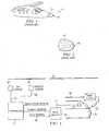
- Figure 3shows a block diagram of an anti-icing system 19 according to the invention.
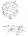
- System 19comprises a controller 21, or control module, for operating heating elements 23 embedded in a radome 25, which is depicted in Figure 4 .
- radome 25is mounted on an aircraft 27 for enclosing components 29 of a radar system carried by aircraft 29.
- Aircraft 27has a fuselage 31 and wings 33 for producing lift.
- aircraft 27carries a sensor 35 for sensing outside air temperature (OAT) and a sensor 37 for sensing the speed of air passing over the radome.
- Controller 21selectively switches through cable 38 a relay module 39 for controlling the flow of electrical power through supply lines 40 to heating elements 23.
- At least one sensor 41is embedded in radome 25 for sensing the temperature of heated portions of radome 25.
- Sensor 41is shown in an example position on radome 25 in Figure 4 , though sensor 41 is typically located within a every close distance to heating elements 23, such as, for example, a few thousandths of an inch.
- radome 25will preferably be formed to have a plurality of sensors 41 for sensing the temperature of radome 25 throughout a large surface area.
- Output from sensors 35, 37is supplied to an embedded computer in controller 21 through cables 43, 45, respectively.
- the computeruses a lookup table to ascertain the appropriate duty cycle of heating time for that OAT and airspeed combination, and controller 21 then applies that duty cycle until a different duty cycle is selected or operation of elements 23 is terminated.
- Each embedded temperature sensor 41is used as a feedback element for the temperature of radome 25, and the output from sensor 41 is supplied to controller 21 through cable 47. It is preferred that the output from OAT sensor 35 be filtered to show the lowest peak temperature in a given time period, preventing system 19 from "chasing" a constantly changing OAT.
- FIGS 6A through 6Dshow example duty cycles constructed using a 250-millisecond interval (4 Hertz).
- controller 21will signal relay module 39 to continuously supply electrical power to heating elements 23 during all time intervals ( Figure 4 ) until system 19 is switched off or until a new duty cycle is selected. This provides, in the example shown, a total power of 5,000 Watts to heating elements 23.
- controller 21will signal relay module 39 to provide power in an alternating pattern of 250 milliseconds "on,” when power is supplied to heating elements 23, and 250 milliseconds "off,” when power is not supplied to elements 23. This results in electrical power being supplied to elements 23 for 50% of the operational time, which also equates to 50% of the total power, or 2,500 Watts. All duty cycles are derived from the base interval, and this base interval may be any appropriate value as determined for the particular application.
- example duty cycles having the desired amount of powerare constructed as follows:
- nmber of ⁇ on ⁇ intervals / total number of ⁇ on ⁇ and ⁇ off ⁇ intervals% power
- Radome 25is heated until upper control temperature 49 is reached again.
- An appropriate duty cycle and an appropriate control temperature band 53are associated with all OAT and airspeed combinations, and as the airspeed increases and the temperature conduction characteristics of radome 25 changes, the control temperatures may be adjusted by system 19 in order to maintain effective anti-ice operation.
- the optimum situationis for the radome to have a constant temperature within control temperature band 53.
- ambient conditionsmay change during use of radome 25, requiring application of varying amounts of power to keep ice from forming on radome 25.
- the objective of the duty cycle controlis to deliver the appropriate amount of power to radome 15 for that particular flight regime.
- System 19is adaptive, in that controller 21 monitors the rate of heating of radome 25 using temperature sensor 41, and if a desired rate of heating is not achieved over a given time interval due to conditions such as low generator voltage or water droplets on radome 25, controller 21 will gradually increase the duty cycle setting to maintain the expected rate of heating up to an overriding maximum rate determined for the particular application. If the rate of heating is too rapid, or if overshoot of upper control temperature 51 exists, then controller 21 gradually decreases the duty cycle setting to bring the rate of heating to the desired rate.
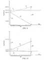
- Figure 7shows an example schedule for heating radome 25, in which the rate of heating is scheduled against the temperature of radome 25, as sensed by sensor 41.
- the heating rates shows in the graphare:
- Figure 8is an example of a combination of duty cycles used to heat radome 25 according to the heating rates shown in Figure 7 .
- controller 21uses a progression of 25%, 50%, and 66% duty cycles. Afterward, a 50% duty cycle is selected until lower control temperature 49 is reached, at which time a combination of a 33% duty cycle and a 50% duty cycle is used to heat radome 25 to upper control temperature 51. Controller 21 then switches off power to heating elements 23 until lower control temperature 49 is reached, when controller 21 reapplies the last good power setting of a 50% duty cycle.
- controller 21may select any of the available duty cycles and in any combination or sequence. The duty cycles selected by controller 21 for any temperature range will be based on the factors described above, including ambient conditions and heating rate of radome 25.
- a combination of duty cycles required to achieve a desired heating rate for a particular regionmay be determined through experimentation.
- thisis especially true for the initial region below 100°C.
- one appropriate method of heating radome 25 from the initial temperature to 100°Cis to apply power using the lowest available duty cycle, and then increase the duty cycle every 30 seconds until radome 25 reaches 100°C.
- system 19monitors for excessive rates of heating, such a progressive schedule has been found to heat radome in an effective manner without exceeding the overriding rate of 10°C per second.
- controller 21may be implemented in controller 21 to prevent overshoot of upper control temperature 51 or undershoot of control temperatures 49 when system 19 is operating within control temperature band 53, such as shown in Figures 7 and 8 .
- controller 21makes a prediction of the temperature of radome 25 at the end of the next time interval to determine whether to apply the "on" or "off" condition that is next in the sequence for that duty cycle.
- controller 21logs (1) the current temperature of radome 25, (2) the rate of change of temperature of radome 25 during the current time Interval, and (3) the rate of change of temperature of radome 25 during the most recent time interval in which the "on" or "off” condition was the opposite of the condition in the current time interval. Controller 21 then uses these data to calculate the predicted temperature at the end of the next time interval, allowing for a prediction of undershoot or overshoot due to operation according to the condition called for in the next time interval of the duty cycle.
- Figures 9 and 10illustrate examples of use of the predictor function of the present invention.
- the temperature of radome 25 near the end of a current time intervalis 119.8°C, which is plotted on the graph at point A.
- controller 21calculates a predicted temperature for the end of the next interval by using the current temperature and the rate of change of temperature logged during the most recent "on" interval. If this rate of change of temperature was +2°C per second, then that rate over a 250-millisecond time interval would cause a 0.5°C rise in the temperature of radome 25.
- the predicted temperature for the end of the next intervalis 120.3°C, which is shown on the graph at point B.
- This temperaturewould overshoot upper control temperature 51 approximately halfway through the time interval, as shown by sloping line 61.
- controller 21then alters the application of the current duty cycle, in that the next time interval is changed from an "on” interval to an "off” interval, proactively preventing the temperature of radome 25 from overshooting upper control temperature 51.
- the actual temperature of radome 25falls during interval 55, as shown by sloping line 63, to a lower temperature, such as the temperature shown at point C.
- controller 21ends the application of the duty cycle until the temperature of radome 25 falls to near lower control temperature 49.
- controller 21reapplies the last duty cycle to prevent the undershoot and maintain the temperature of radome 25 within control band 53.
- controller 21calculates a predicted temperature for the end of the next interval by using the current temperature and the rate of change of temperature logged during the most recent "off" interval. If this rate of change of temperature was -1°C per second, then that rate over a 250-millisecond time interval would cause a 0.25°C decrease in the temperature of radome 25.
- the predicted temperature for the end of the next intervalis 109.85°C, which is shown on the graph at point E.
- This temperaturewould undershoot lower control temperature 49 during the time interval, as shown by sloping line 71.
- controller 21alters the application of the current duty cycle, in that the next time interval is changed from an "off" interval to an "on” interval, proactively preventing the temperature of radome 25 from undershooting lower control temperature 49.
- the actual temperature of radome 25rises during interval 65, as shown by sloping line 73, to a higher temperature, such as the temperature shown at point F.
- the temperature of radome 25is then logged for prediction of the temperature at the end of the next interval, and the rate of change during interval 65 is logged for use in predictions for subsequent "on" time intervals.
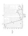
- Figure 11illustrates an example track 75 of temperature when duty-cycle control is combined with the predictor functions described above.
- lower control temperature 49is 100°C
- upper control temperature 51is 110°C
- a 80% duty cycleis being used.
- the exampleuses 125 millisecond time intervals, a heating rate of +2.7°C per second, and a cooling rate of -24°C per second.
- the 80% duty cyclecalls for application of power to heating elements 23 ( Fig. 3 ), these being the "on" intervals of the duty cycle.
- Line 77 of track 75shows the heating of radome 25 in intervals 1-3 while power is supplied to heating elements 23.
- controller 21predicts the temperature at the end of the next interval. In the example illustrated, the application of power in interval 4 would result in an overshoot of upper control temperature 51, as shown by broken line 79. The predictor function of controller 21 predicts this overshoot, as described above, and controller 21 turns off power to heating elements 23.
- controller 21When heating elements 23 are not operating, the temperature of radome 25 falls, as shown by line 81.
- controller 21reapplies power according to the previously selected duty cycle.
- the temperature of radome 25rises, as shown by line 85, as power is applied through intervals 8-11 according to the 80% duty cycle.
- the following intervalis an "off" interval in the duty cycle, but controller 21 predicts that the cooling rate of radome 25 would result in an undershoot of lower control temperature 49 in interval 12, shown by broken line 87.
- controller 21restarts application of the duty cycle sequence in interval 12, applying power through 4 intervals, as shown by line 89. This is followed by an "off" interval in interval 16, shown by line 91, and the duty cycle sequence restarts in frame 17, shown by line 93.
- the duty cycle controlis an economical way of controlling the electrical power supplied to radome 25 without requiring an expensive variable-voltage power supply.
- the fine power controlis essential to preclude overshooting upper control temperature 51 due to thermal inertia.
- the adjustment of control temperature band 53is essential due to the changing heat exchange characteristics of radome 25 with different airspeeds.
- the adaptive power controlis needed to compensate for fluctuations in generator power and due to the presence or absence water droplets on radome 25.
- the use of a predictor functionalso acts to assist in maintaining the temperature within band 53. The combination of all of these, scheduled for airspeed and OAT, allows for an effective anti-ice system 19 for radomes.
- the present inventionprovides an ice management system with many advantages, including: (1) scheduling of the duty-cycle power control with OAT and airspeed; (2) scheduling the adjustable control-temperature band with OAT and airspeed; (3) adaptive power control to compensate for ambient conditions; (4) light weight and small size, which allows for use on, e.g., unmanned aerial vehicles and cruise missiles; (5) relatively low expense; and (6) a system particularly suited for use with thin materials, such as radomes.
Landscapes
- Engineering & Computer Science (AREA)
- Aviation & Aerospace Engineering (AREA)
- Details Of Aerials (AREA)
- Control Of Temperature (AREA)
- Control Of Resistance Heating (AREA)
- Defrosting Systems (AREA)
- Radar Systems Or Details Thereof (AREA)
Description
- The present invention relates generally to the field of anti-icing systems and relates particularly to anti-icing systems for thin materials.
Figure 1 shows a forward portion of anaircraft 11 havingradar system components 13 mounted in the nose section ofaircraft 11.Components 13 are protected from impinging air and debris by aradome 15, which is removable for accessingcomponents 13. During flight,aircraft 11 will typically encounter low ambient air temperatures and moisture, the combination of which may cause ice to form onradome 15, resulting in a reduction in the operational effectiveness ofcomponents 13.- Ice management for a radar radome, such as
radome 15, is a unique endeavor, in that radomes are typically made of materials that do not interfere with the radar operation, such as one or more types of plastics. To prevent ice accumulation or to eliminate accumulated ice, electro-thermal heating elements 17 embedded inradome 15, as shown inFigure 2 , are used to heat at least the outer surface ofradome 15.Elements 17 are located withinradome 15 with an appropriate spacing as to not interfere with the radar operation and may be configured in other, more intricate configurations. - During icing conditions, electrical power is supplied to
elements 17, causing the temperature ofelements 17 to increase, which warms the materialadjacent elements 17. The amount of power supplied must be carefully controlled, however, as application of too much power can degrade and even destroy the material ofradome 15. On the other hand, application of insufficient power will allowradome 15 to accumulate ice and render the radar less effective. - Prior-art ice management systems have applied varying power to
elements 17 using devices for varying the voltage supplied toelements 17. While the variable-voltage systems are effective, they are expensive, increasing the cost of the aircraft. - In addition, the variable-voltage systems tend to be relatively heavy and bulky, limiting the number of applications in which these systems can effectively be deployed.
- Examples of known ice management systems for a structure using sensors adapted for measuring the surface temperature of the structure are disclosed in
WO-A-88 09980 US-A-5 354 015 . - In
WO-A-88 09980 claim 1. - It is against this background, and the limitations and problems associated therewith, that the present invention has been developed.
- Therefore, it is a primary objective of the present invention to provide an ice management system for a structure, such as a radome exposed to atmospheric conditions, in which the system controls the operation of heating elements carried by at least a portion of the structure according to a selected duty cycle that defines time intervals of application of electrical power to the heating elements.
- To achieve this, the system of the invention is characterized by the features claimed in the characterizing part of
claim 1. - It is a feature of the present invention to provide an ice management system that selects a duty cycle based at least partially on ambient conditions, such as air temperature and air velocity, near the structure.
- It is yet another feature of the present invention to provide an ice management system that selects a duty cycle based at least partially on a measured temperature of the heated portion of the structure.
- The above objects are achieved by providing an ice protection system for a structure, the system having at least one electro-thermal heating element carried by the structure and a controller for selectively controlling the operation of each heating element. The controller operates each heating element according to a selected duty cycle defined by a pattern of time intervals, the controller selecting the duty cycle at least partially in response to measurements of ambient conditions about the structure. The controller may additionally or alternatively select the duty cycle at least partially in response to the temperature of the heated portion of the structure.
- The present invention provides an ice management system with many advantages, including: (1) scheduling of the duty-cycle power control with OAT and airspeed; (2) scheduling the adjustable control-temperature band with OAT and airspeed; (3) adaptive power control to compensate for ambient conditions; (4) light weight and small size, which allows for use on, e.g., unmanned aerial vehicles and cruise missiles; (5) relatively low expense; and (6) a system particularly suited for use with thin materials, such as radomes.
- Additional objectives, features, and advantages will be apparent in the written description that follows.
- For a more complete understanding of the present invention, including its features and advantages, reference is now made to the detailed description of the invention taken in conjunction with the accompanying drawings in which like numerals identify like parts, and in which:
FIG. 1 is a perspective view of a front portion of a prior-art aircraft having a radar system covered by a radome;FIG. 2 is a perspective view of the prior-art radome ofFigure 1 showing heating elements embedded in the radome;FIG. 3 is a diagram of an ice management system according to the invention;FIG. 4 is a perspective view of a radome according to the invention and showing a particular configuration of heating elements;FIG. 5 is a perspective view of a front portion of an aircraft according to the invention, the ice management system ofFIG. 3 being installed on the aircraft;FIGS. 6A through 6D are graphs showing examples of duty cycles according to the invention and used by the system ofFIG. 3 ;FIG. 7 is a graph of time vs. temperature for an example heating rate schedule according to the invention and used by the system ofFIG. 3 ;FIG. 8 is a graph of time vs. temperature showing the combination of duty cycles used to achieve the heating rates shown inFIG. 7 ;FIG. 9 is a graph illustrating the use of a predictor function implemented in the system of the invention and acting to prevent overshoot of an upper control temperature;FIG. 10 is a graph illustrating the use of a predictor function implemented in the system of the invention and acting to prevent undershoot of a lower control temperature; andFIG. 11 is a graph showing the use over time of duty-cycle control and a predictor function to maintain a temperature of a radome within a control-temperature band.- The present invention represents the discovery that an ice management system having heating elements may be operated according to a duty-cycle control scheme to heat a structure. The duty cycle is selected by a controller based on measurements of one or more ambient conditions, such as outside air temperature (OAT) and airspeed. The duty cycle may be additionally or alternatively selected based on measurements of the temperature and rates of temperature increase of heated portions of the structure.
- A duty cycle comprises a pattern of "on" and "off' commands, each command lasting for a selected number of time intervals. The duty cycle time interval, or frame, may be any appropriate time interval, though the interval must be small enough to achieve a smooth heat exchange to the surrounding structure. Each duty cycle for a given application preferably uses the same base time interval, though the interval size, and resulting frame rate, may be changed as desired.
- The present invention is particularly suited for use as an anti-icing system for structures formed of thin materials. An example of such a structure is a radome, such as
radome 15, which is required to be thin for ensuring limited interference with transmission of electromagnetic radiation through the radome. Structures may also be required to be thin for weight considerations, such as structures carried on an aircraft. It is usually desirable to maintain a certain level of heat within a thin structure to prevent ice from initially forming thereon, since these structures generally cannot be heated enough to shed ice. An additional consideration is that the colder a thin structure is, the easier it is to damage with overheating. Though the present invention is described in reference to radomes for airborne radar systems, the invention is also applicable to radomes for ground- or sea-based radar systems and to any other structure having electro-thermal heating elements used for ice protection. - Referring to
Figures 3 through 5 ,Figure 3 shows a block diagram of ananti-icing system 19 according to the invention.System 19 comprises acontroller 21, or control module, foroperating heating elements 23 embedded in aradome 25, which is depicted inFigure 4 . As shown inFigure 5 ,radome 25 is mounted on anaircraft 27 for enclosingcomponents 29 of a radar system carried byaircraft 29.Aircraft 27 has afuselage 31 andwings 33 for producing lift. - Referring again to
Figure 3 ,aircraft 27 carries asensor 35 for sensing outside air temperature (OAT) and asensor 37 for sensing the speed of air passing over the radome.Controller 21 selectively switches through cable 38 arelay module 39 for controlling the flow of electrical power throughsupply lines 40 toheating elements 23. At least onesensor 41 is embedded inradome 25 for sensing the temperature of heated portions ofradome 25.Sensor 41 is shown in an example position onradome 25 inFigure 4 , thoughsensor 41 is typically located within a every close distance toheating elements 23, such as, for example, a few thousandths of an inch. Though only one embeddedsensor 41 is shown,radome 25 will preferably be formed to have a plurality ofsensors 41 for sensing the temperature ofradome 25 throughout a large surface area. - Output from
sensors controller 21 throughcables controller 21 then applies that duty cycle until a different duty cycle is selected or operation ofelements 23 is terminated. Each embeddedtemperature sensor 41 is used as a feedback element for the temperature ofradome 25, and the output fromsensor 41 is supplied tocontroller 21 throughcable 47. It is preferred that the output fromOAT sensor 35 be filtered to show the lowest peak temperature in a given time period, preventingsystem 19 from "chasing" a constantly changing OAT. Figures 6A through 6D show example duty cycles constructed using a 250-millisecond interval (4 Hertz). For example, if the appropriate duty cycle is 100%, which is shown inFigure 6A ,controller 21 will signalrelay module 39 to continuously supply electrical power toheating elements 23 during all time intervals (Figure 4 ) untilsystem 19 is switched off or until a new duty cycle is selected. This provides, in the example shown, a total power of 5,000 Watts toheating elements 23. If a 50% duty cycle, as shown inFigure 6C , is selected,controller 21 will signalrelay module 39 to provide power in an alternating pattern of 250 milliseconds "on," when power is supplied toheating elements elements 23. This results in electrical power being supplied toelements 23 for 50% of the operational time, which also equates to 50% of the total power, or 2,500 Watts. All duty cycles are derived from the base interval, and this base interval may be any appropriate value as determined for the particular application.- For any interval, example duty cycles having the desired amount of power are constructed as follows:
- 25% - one interval on, three intervals off, as shown in
Figure 6D - 33% - one interval on, two intervals off
- 50% - one interval on, one interval off
- 66% - two intervals on, one interval off
- 75% - three intervals on, one interval off, as shown in
Figure 6B - 80% - four intervals on, one interval off
- These are examples, in that a duty cycle having a desired power level may be constructed by combining "on" and "off" intervals in a combination using the formula:

For example, a duty cycle having 3 intervals on and two intervals off is calculated as providing 60% of the total power:
- Referring to
Figure 7 and 8 , in addition to duty cycles being scheduled for a given OAT and airspeed, there is also an associated "on"temperature 49 and "off"temperature 51 ofradome 25 for each given airspeed and OAT regime.Temperatures control temperature band 53 betweentemperatures Temperatures band 53, are adjusted higher or lower as airspeed and OAT change. While system 19 (Figure 3 ) is operating, the selected duty cycle would be applied untilupper control temperature 49 is reached, then power toheating elements 23 is switched off.Radome 25 then cools untillower control temperature 51 is reached, at which point power is reapplied toelements 23 using the previously selected duty cycle.Radome 25 is heated untilupper control temperature 49 is reached again. An appropriate duty cycle and an appropriatecontrol temperature band 53 are associated with all OAT and airspeed combinations, and as the airspeed increases and the temperature conduction characteristics ofradome 25 changes, the control temperatures may be adjusted bysystem 19 in order to maintain effective anti-ice operation. - The optimum situation is for the radome to have a constant temperature within
control temperature band 53. However, ambient conditions may change during use ofradome 25, requiring application of varying amounts of power to keep ice from forming onradome 25. As mentioned above, the objective of the duty cycle control is to deliver the appropriate amount of power to radome 15 for that particular flight regime.System 19 is adaptive, in thatcontroller 21 monitors the rate of heating ofradome 25 usingtemperature sensor 41, and if a desired rate of heating is not achieved over a given time interval due to conditions such as low generator voltage or water droplets onradome 25,controller 21 will gradually increase the duty cycle setting to maintain the expected rate of heating up to an overriding maximum rate determined for the particular application. If the rate of heating is too rapid, or if overshoot ofupper control temperature 51 exists, thencontroller 21 gradually decreases the duty cycle setting to bring the rate of heating to the desired rate. Figure 7 shows an example schedule forheating radome 25, in which the rate of heating is scheduled against the temperature ofradome 25, as sensed bysensor 41. The heating rates shows in the graph are:- Below 100°C
If the temperature ofradome 25 is below 100°C, the desired heating rate is 10°C per second.System 19 starts operation ofheating elements 23 at the minimum duty cycle and updates the selection of duty cycle once per second to achieve the desired rate of increase of 10°C per second. - Between 100°C and
lower control temperature 49
If the temperature ofradome 25 is between 100°C andlower control temperature 49, the desired heating rate is 5°C per second.System 19 updates the selection of duty cycle once per second to achieve the desired rate of increase of 5°C per second. - Within
control temperature band 53
If the temperature ofradome 25 is withincontrol temperature band 53, the desired heating rate is 2°C per second.System 19 updates the selection of duty cycle once per second to achieve the desired rate of increase of 2°C per second.System 19 also monitors the upper control temperature at 4 Hz.
Whenupper control temperature 51 is reached, electrical power toheating elements 23 is removed untillower control temperature 49 is reached, then the last known good duty-cycle setting is applied and monitored for the same 2°C increase per second. Figure 8 is an example of a combination of duty cycles used to heatradome 25 according to the heating rates shown inFigure 7 . In the example shown, to obtain the desired rate of increase of 10°C per second (as in the example shown inFigure 7 ) up to 100°C,controller 21 uses a progression of 25%, 50%, and 66% duty cycles. Afterward, a 50% duty cycle is selected untillower control temperature 49 is reached, at which time a combination of a 33% duty cycle and a 50% duty cycle is used to heatradome 25 toupper control temperature 51.Controller 21 then switches off power toheating elements 23 untillower control temperature 49 is reached, whencontroller 21 reapplies the last good power setting of a 50% duty cycle. In a particular application,controller 21 may select any of the available duty cycles and in any combination or sequence. The duty cycles selected bycontroller 21 for any temperature range will be based on the factors described above, including ambient conditions and heating rate ofradome 25.- Alternatively, a combination of duty cycles required to achieve a desired heating rate for a particular region may be determined through experimentation. In the example of
radome 25, this is especially true for the initial region below 100°C. For example, it has been determined from experimental data that one appropriate method ofheating radome 25 from the initial temperature to 100°C is to apply power using the lowest available duty cycle, and then increase the duty cycle every 30 seconds untilradome 25reaches 100°C. Though system 19 monitors for excessive rates of heating, such a progressive schedule has been found to heat radome in an effective manner without exceeding the overriding rate of 10°C per second. - In addition, a predictor function may be implemented in
controller 21 to prevent overshoot ofupper control temperature 51 or undershoot ofcontrol temperatures 49 whensystem 19 is operating withincontrol temperature band 53, such as shown inFigures 7 and 8 . For every time interval in a duty cycle,controller 21 makes a prediction of the temperature ofradome 25 at the end of the next time interval to determine whether to apply the "on" or "off" condition that is next in the sequence for that duty cycle. Using the output fromsensors 41,controller 21 logs (1) the current temperature ofradome 25, (2) the rate of change of temperature ofradome 25 during the current time Interval, and (3) the rate of change of temperature ofradome 25 during the most recent time interval in which the "on" or "off" condition was the opposite of the condition in the current time interval.Controller 21 then uses these data to calculate the predicted temperature at the end of the next time interval, allowing for a prediction of undershoot or overshoot due to operation according to the condition called for in the next time interval of the duty cycle. Figures 9 and 10 illustrate examples of use of the predictor function of the present invention. InFigure 9 , for example, the temperature ofradome 25 near the end of a current time interval is 119.8°C, which is plotted on the graph at point A. If thenext interval 55, bounded bydotted lines controller 21 calculates a predicted temperature for the end of the next interval by using the current temperature and the rate of change of temperature logged during the most recent "on" interval. If this rate of change of temperature was +2°C per second, then that rate over a 250-millisecond time interval would cause a 0.5°C rise in the temperature ofradome 25. Thus, the predicted temperature for the end of the next interval is 120.3°C, which is shown on the graph at point B. This temperature would overshootupper control temperature 51 approximately halfway through the time interval, as shown by slopingline 61. To avoid the overshoot,controller 21 then alters the application of the current duty cycle, in that the next time interval is changed from an "on" interval to an "off" interval, proactively preventing the temperature ofradome 25 from overshootingupper control temperature 51. The actual temperature ofradome 25 falls duringinterval 55, as shown by slopingline 63, to a lower temperature, such as the temperature shown at point C. The temperature ofradome 25 is then logged for prediction of the temperature at the end of the next interval, and the rate of change duringinterval 55 is logged for use in predictions for subsequent "off" time intervals. In the preferred embodiment, when an overshoot is predicted,controller 21 ends the application of the duty cycle until the temperature ofradome 25 falls to nearlower control temperature 49. When the predictor function predicts an undershoot, as described below,controller 21 reapplies the last duty cycle to prevent the undershoot and maintain the temperature ofradome 25 withincontrol band 53.- As shown in
Figure 10 , a similar prediction and altering of power delivery is done for an "off" interval to predict undershoot oflower control temperature 49. For example, the temperature ofradome 25 near the end of a current time interval is 110.1°C, which is plotted on the graph at point D. If thenext interval 65, bounded bydotted lines controller 21 calculates a predicted temperature for the end of the next interval by using the current temperature and the rate of change of temperature logged during the most recent "off" interval. If this rate of change of temperature was -1°C per second, then that rate over a 250-millisecond time interval would cause a 0.25°C decrease in the temperature ofradome 25. Thus, the predicted temperature for the end of the next interval is 109.85°C, which is shown on the graph at point E. This temperature would undershootlower control temperature 49 during the time interval, as shown by slopingline 71. To avoid the undershoot,controller 21 then alters the application of the current duty cycle, in that the next time interval is changed from an "off" interval to an "on" interval, proactively preventing the temperature ofradome 25 from undershootinglower control temperature 49. The actual temperature ofradome 25 rises duringinterval 65, as shown by slopingline 73, to a higher temperature, such as the temperature shown at point F. The temperature ofradome 25 is then logged for prediction of the temperature at the end of the next interval, and the rate of change duringinterval 65 is logged for use in predictions for subsequent "on" time intervals. Figure 11 illustrates anexample track 75 of temperature when duty-cycle control is combined with the predictor functions described above. In the example shown,lower control temperature 49 is 100°C,upper control temperature 51 is 110°C, and a 80% duty cycle is being used. In addition, the example uses 125 millisecond time intervals, a heating rate of +2.7°C per second, and a cooling rate of -24°C per second.- In time intervals 1-4, the 80% duty cycle calls for application of power to heating elements 23 (
Fig. 3 ), these being the "on" intervals of the duty cycle. Line 77 oftrack 75 shows the heating ofradome 25 in intervals 1-3 while power is supplied toheating elements 23. During all time intervals whilesystem 19 is operating,controller 21 predicts the temperature at the end of the next interval. In the example illustrated, the application of power ininterval 4 would result in an overshoot ofupper control temperature 51, as shown bybroken line 79. The predictor function ofcontroller 21 predicts this overshoot, as described above, andcontroller 21 turns off power toheating elements 23. - When heating
elements 23 are not operating, the temperature ofradome 25 falls, as shown by line 81. When the temperature in the next interval is predicted to undershootlower control temperature 49, as shown ininterval 8 bybroken line 83,controller 21 reapplies power according to the previously selected duty cycle. In the example, the temperature ofradome 25 rises, as shown byline 85, as power is applied through intervals 8-11 according to the 80% duty cycle. The following interval is an "off" interval in the duty cycle, butcontroller 21 predicts that the cooling rate ofradome 25 would result in an undershoot oflower control temperature 49 ininterval 12, shown by broken line 87. To prevent the undershoot,controller 21 restarts application of the duty cycle sequence ininterval 12, applying power through 4 intervals, as shown byline 89. This is followed by an "off" interval ininterval 16, shown byline 91, and the duty cycle sequence restarts inframe 17, shown byline 93. - Since the instantaneous available electrical power is too much for the application, the duty cycle control is an economical way of controlling the electrical power supplied to
radome 25 without requiring an expensive variable-voltage power supply. The fine power control is essential to preclude overshootingupper control temperature 51 due to thermal inertia. In addition, the adjustment ofcontrol temperature band 53 is essential due to the changing heat exchange characteristics ofradome 25 with different airspeeds. Also, the adaptive power control is needed to compensate for fluctuations in generator power and due to the presence or absence water droplets onradome 25. The use of a predictor function also acts to assist in maintaining the temperature withinband 53. The combination of all of these, scheduled for airspeed and OAT, allows for aneffective anti-ice system 19 for radomes. - The present invention provides an ice management system with many advantages, including: (1) scheduling of the duty-cycle power control with OAT and airspeed; (2) scheduling the adjustable control-temperature band with OAT and airspeed; (3) adaptive power control to compensate for ambient conditions; (4) light weight and small size, which allows for use on, e.g., unmanned aerial vehicles and cruise missiles; (5) relatively low expense; and (6) a system particularly suited for use with thin materials, such as radomes.


Claims (11)
- An ice management system (19) for a structure (25), the system (19) comprising:at least one electro-thermal heating element (23) carried by the structure (25) for heating a heated portion of the structure (25);a controller (21) for selectively controlling the operation of each heating element (23),an outside air temperature sensor; andat least one embedded temperature sensor carried by the structure for sensing a temperature of a portion of the heated portion;characterized in that the controller (21) operates each heating element (23) according to a selected duty cycle defined by a pattern of time intervals, the controller (21) selecting the duty cycle at least partially in response (43, 45) to measurements of an air temperature (OAT) from the outside air temperature sensor and a velocity of air passing over the structure (25), the controller (21) selecting the duty cycle to approximately maintain a rate of increase of a temperature of the heated portion to a selected rate;wherein the controller selects the duty cycle at least partially in response to an output of the at least one embedded temperature sensor; andwherein the at least one embedded temperature sensor is no more than a few multiples of 25 microns (thousandths of an inch) from the at least one electro-thermal heating element.
- The system according to claim 1,characterized in that each time interval is a pre-determined length.
- The system according to claim 1,characterized in that the time intervals are of equal length.
- The system according to claim 1,characterized in that each time interval is about 250 milliseconds.
- The system according to claim 1,characterized in that the measurements of ambient conditions include a measurement of moisture about the structure (25).
- The system according to claim 1,
wherein the controller includes a predictor function;
wherein the predictor function prevents overheating and underheating of the structure;
wherein the predictor function is based at least on the temperature of a portion of the heated portion, a rate of change in the temperature of a portion of the heated portion during the time interval while the at least one electro-thermal heating element is on, and a rate of change in the temperature of a portion of the heated portion during the time interval while the at least one electro-thermal heating element is off; and
wherein the controller selects the duty cycle at least partially in response to a output of the predictor function. - The system according to claim 1,characterized in further comprising:at least one ice detection sensor:wherein the controller (21) selects the duty cycle at least partially in response to a output of the at least one ice detection sensor.
- The system according to claim 1,characterized in that the controller (21) selects the duty cycle that approximately maintains a temperature of the heated portion within a selected temperature range.
- The system according to claim 1,characterized in that the structure (25) is a thin material.
- The system according to claim 1,characterized in that the structure (25) is a radome (25) adapted for enclosing a radar system (29).
- The system according to claim 1,characterized in that each heating element (23) is configured to allow transmission of at least a selected frequency of electromagnetic energy through the structure (25).
Applications Claiming Priority (2)
| Application Number | Priority Date | Filing Date | Title |
|---|---|---|---|
| US57864904P | 2004-06-10 | 2004-06-10 | |
| PCT/US2004/041266WO2006001830A2 (en) | 2004-06-10 | 2004-12-09 | Anti-icing system for radomes |
Publications (3)
| Publication Number | Publication Date |
|---|---|
| EP1767063A2 EP1767063A2 (en) | 2007-03-28 |
| EP1767063A4 EP1767063A4 (en) | 2009-06-10 |
| EP1767063B1true EP1767063B1 (en) | 2014-06-18 |
Family
ID=35782202
Family Applications (1)
| Application Number | Title | Priority Date | Filing Date |
|---|---|---|---|
| EP04821783.0AExpired - LifetimeEP1767063B1 (en) | 2004-06-10 | 2004-12-09 | Anti-icing system for radomes |
Country Status (6)
| Country | Link |
|---|---|
| US (1) | US8969765B2 (en) |
| EP (1) | EP1767063B1 (en) |
| CN (1) | CN101411243B (en) |
| BR (1) | BRPI0418889A (en) |
| CA (1) | CA2569053C (en) |
| WO (1) | WO2006001830A2 (en) |
Families Citing this family (18)
| Publication number | Priority date | Publication date | Assignee | Title |
|---|---|---|---|---|
| EP2004488B1 (en)* | 2006-03-17 | 2012-04-25 | Ultra Electronics Limited | Ice protection system |
| US8331888B2 (en)* | 2006-05-31 | 2012-12-11 | The Boeing Company | Remote programmable reference |
| US8280674B2 (en)* | 2008-01-24 | 2012-10-02 | Raytheon Company | Apparatus for measuring surface temperature using embedded components |
| TWI501534B (en)* | 2011-01-21 | 2015-09-21 | Delta Electronics Inc | System and method for controlling quasi-resonant inverter and electric heating device employing the same |
| US8541720B2 (en) | 2011-04-12 | 2013-09-24 | Raytheon Company | Apparatus for remotely measuring surface temperature using embedded components |
| DE102011078746A1 (en)* | 2011-07-06 | 2013-01-10 | Robert Bosch Gmbh | Device for detecting object i.e. airplane, during docking of object at gate of airport, has measuring device for detecting distance pattern and detecting object in area when portion of distance pattern remains constant temporally |
| DE102012002132A1 (en) | 2012-02-03 | 2013-08-08 | Airbus Operations Gmbh | Anti-icing system for an aircraft and method of operating an anti-icing system |
| EP2692640A3 (en)* | 2012-07-31 | 2017-04-19 | Goodrich Corporation | Ice protection system |
| CN105329445A (en)* | 2015-10-10 | 2016-02-17 | 中国商用飞机有限责任公司 | Electric heating ice prevention/removal control method for fixed-wing aircraft |
| US10543926B2 (en)* | 2015-12-21 | 2020-01-28 | Sikorsky Aircraft Corporation | Ice protection systems |
| CN106892123A (en)* | 2015-12-21 | 2017-06-27 | 中国航空工业集团公司西安飞机设计研究所 | A kind of electrothermal frontal windshield heating system |
| US10442539B2 (en)* | 2017-05-12 | 2019-10-15 | Bell Helicopter Textron Inc. | Anti-ice system for thermally fragile materials |
| GB2565842B (en)* | 2017-08-25 | 2020-04-01 | Ge Aviat Systems Ltd | Method and apparatus for predicting conditions favorable for icing |
| US10710732B2 (en) | 2017-09-15 | 2020-07-14 | Bell Helicopter Textron Inc. | Rotary aircraft ice protection system |
| US20190377064A1 (en)* | 2018-06-06 | 2019-12-12 | GM Global Technology Operations LLC | Method and apparatus for deicing of sensor systems in a vehicle |
| CN108820227B (en)* | 2018-07-03 | 2021-12-03 | 上海工程技术大学 | Predictive ice prevention and removal method utilizing graphene heating film |
| US11465759B2 (en)* | 2018-07-13 | 2022-10-11 | The Boeing Company | Multi-mode generator for ice protection on aircraft |
| KR102692546B1 (en)* | 2022-03-18 | 2024-08-06 | 엘아이지넥스원 주식회사 | The apparatus, method, and system for controlling heat generation of a homing sensor mounted on an aircraft |
Citations (3)
| Publication number | Priority date | Publication date | Assignee | Title |
|---|---|---|---|---|
| US3002718A (en)* | 1960-07-08 | 1961-10-03 | Kaman Aircraft Corp | Rotor blade deicing system |
| EP0855340A2 (en)* | 1997-01-21 | 1998-07-29 | The B.F. Goodrich Company | Hybrid deicer with element sequence control |
| US20030155467A1 (en)* | 2002-02-11 | 2003-08-21 | Victor Petrenko | Systems and methods for modifying an ice-to-object interface |
Family Cites Families (16)
| Publication number | Priority date | Publication date | Assignee | Title |
|---|---|---|---|---|
| DE2443224C3 (en)* | 1974-09-10 | 1979-02-22 | Licentia Patent-Verwaltungs-Gmbh, 6000 Frankfurt | Process for deicing engine, wing and tail unit systems on missiles |
| US4292502A (en)* | 1979-02-05 | 1981-09-29 | The B.F. Goodrich Company | Helicopter deicer control system |
| US4980673A (en) | 1987-06-10 | 1990-12-25 | Rosemount Inc. | Ice detector circuit |
| US5011098A (en)* | 1988-12-30 | 1991-04-30 | The Boeing Company | Thermal anti-icing system for aircraft |
| JPH03175510A (en) | 1989-12-04 | 1991-07-30 | Sharp Corp | Heater temperature controller |
| US5528249A (en)* | 1992-12-09 | 1996-06-18 | Gafford; George | Anti-ice radome |
| US5354015A (en)* | 1993-08-10 | 1994-10-11 | Meador Robert H | System for warning the flight crew on board an aircraft of pre-flight aircraft icing |
| JP3175510B2 (en) | 1994-06-29 | 2001-06-11 | 日本鋼管株式会社 | Temperature measuring device for high temperature liquid using optical fiber |
| US5691736A (en)* | 1995-03-28 | 1997-11-25 | Loral Vought Systems Corporation | Radome with secondary heat shield |
| US5657951A (en) | 1995-06-23 | 1997-08-19 | The B.F. Goodrich Company | Electrothermal de-icing system |
| US5709470A (en)* | 1995-07-10 | 1998-01-20 | Cnc Development, Inc. | Method and apparatus for detecting ice buildup |
| US6279856B1 (en)* | 1997-09-22 | 2001-08-28 | Northcoast Technologies | Aircraft de-icing system |
| US6237874B1 (en)* | 1997-09-22 | 2001-05-29 | Northcoast Technologies | Zoned aircraft de-icing system and method |
| US5934617A (en)* | 1997-09-22 | 1999-08-10 | Northcoast Technologies | De-ice and anti-ice system and method for aircraft surfaces |
| US6462313B1 (en)* | 2001-02-20 | 2002-10-08 | Micron Technology, Inc. | Method and apparatus to control temperature in an RTP system |
| US6612673B1 (en)* | 2002-04-29 | 2003-09-02 | Hewlett-Packard Development Company, L.P. | System and method for predicting dynamic thermal conditions of an inkjet printing system |
- 2004
- 2004-12-09EPEP04821783.0Apatent/EP1767063B1/ennot_activeExpired - Lifetime
- 2004-12-09WOPCT/US2004/041266patent/WO2006001830A2/ennot_activeApplication Discontinuation
- 2004-12-09CACA2569053Apatent/CA2569053C/ennot_activeExpired - Lifetime
- 2004-12-09BRBRPI0418889-6Apatent/BRPI0418889A/ennot_activeIP Right Cessation
- 2004-12-09CNCN200480043308.9Apatent/CN101411243B/ennot_activeExpired - Fee Related
- 2004-12-09USUS11/629,021patent/US8969765B2/enactiveActive
Patent Citations (3)
| Publication number | Priority date | Publication date | Assignee | Title |
|---|---|---|---|---|
| US3002718A (en)* | 1960-07-08 | 1961-10-03 | Kaman Aircraft Corp | Rotor blade deicing system |
| EP0855340A2 (en)* | 1997-01-21 | 1998-07-29 | The B.F. Goodrich Company | Hybrid deicer with element sequence control |
| US20030155467A1 (en)* | 2002-02-11 | 2003-08-21 | Victor Petrenko | Systems and methods for modifying an ice-to-object interface |
Also Published As
| Publication number | Publication date |
|---|---|
| US8969765B2 (en) | 2015-03-03 |
| WO2006001830A3 (en) | 2007-02-01 |
| EP1767063A2 (en) | 2007-03-28 |
| CA2569053C (en) | 2014-10-14 |
| CN101411243A (en) | 2009-04-15 |
| BRPI0418889A (en) | 2007-12-11 |
| CN101411243B (en) | 2012-03-28 |
| WO2006001830A2 (en) | 2006-01-05 |
| CA2569053A1 (en) | 2006-01-05 |
| EP1767063A4 (en) | 2009-06-10 |
| US20070295712A1 (en) | 2007-12-27 |
Similar Documents
| Publication | Publication Date | Title |
|---|---|---|
| EP1767063B1 (en) | Anti-icing system for radomes | |
| EP2004488B1 (en) | Ice protection system | |
| US8746622B2 (en) | Aircraft de-icing system and method | |
| EP2202151B1 (en) | Aircraft with an ice protection system | |
| US11414196B2 (en) | Ice protection system and controller | |
| US7708227B2 (en) | Energy-efficient electro-thermal ice-protection system | |
| US4458137A (en) | Electric heater arrangement for fluid flow stream sensors | |
| EP2163475B1 (en) | Propeller deicing system | |
| US5657951A (en) | Electrothermal de-icing system | |
| EP3899267B1 (en) | Improvements relating to wind turbine blade anti-ice systems | |
| US8727607B2 (en) | Method of calibrating a heater system | |
| CA2822630C (en) | Ice protection system | |
| US12325524B2 (en) | Adjustable ice protection system parting strip | |
| US6867391B2 (en) | Control system for electrostatic discharge mitigation | |
| CA3051332A1 (en) | De-icing system and method | |
| HK40042013A (en) | Apparatus and method for detecting water or ice | |
| WO2002026559A1 (en) | Drainmast with integral electronic temperature control |
Legal Events
| Date | Code | Title | Description |
|---|---|---|---|
| PUAI | Public reference made under article 153(3) epc to a published international application that has entered the european phase | Free format text:ORIGINAL CODE: 0009012 | |
| 17P | Request for examination filed | Effective date:20061207 | |
| AK | Designated contracting states | Kind code of ref document:A2 Designated state(s):AT BE BG CH CY CZ DE DK EE ES FI FR GB GR HU IE IS IT LI LT LU MC NL PL PT RO SE SI SK TR | |
| AX | Request for extension of the european patent | Extension state:AL BA HR LV MK YU | |
| RIC1 | Information provided on ipc code assigned before grant | Ipc:H05B 11/00 20060101AFI20070511BHEP Ipc:B64D 15/12 20060101ALI20070511BHEP Ipc:B64D 15/22 20060101ALI20070511BHEP Ipc:B64D 15/20 20060101ALI20070511BHEP | |
| RIN1 | Information on inventor provided before grant (corrected) | Inventor name:DREWES, DONAVAN Inventor name:FROMAN, GARY, S. | |
| DAX | Request for extension of the european patent (deleted) | ||
| A4 | Supplementary search report drawn up and despatched | Effective date:20090512 | |
| 17Q | First examination report despatched | Effective date:20090903 | |
| GRAP | Despatch of communication of intention to grant a patent | Free format text:ORIGINAL CODE: EPIDOSNIGR1 | |
| INTG | Intention to grant announced | Effective date:20140326 | |
| GRAS | Grant fee paid | Free format text:ORIGINAL CODE: EPIDOSNIGR3 | |
| GRAA | (expected) grant | Free format text:ORIGINAL CODE: 0009210 | |
| AK | Designated contracting states | Kind code of ref document:B1 Designated state(s):AT BE BG CH CY CZ DE DK EE ES FI FR GB GR HU IE IS IT LI LT LU MC NL PL PT RO SE SI SK TR | |
| REG | Reference to a national code | Ref country code:GB Ref legal event code:FG4D | |
| REG | Reference to a national code | Ref country code:CH Ref legal event code:EP | |
| REG | Reference to a national code | Ref country code:AT Ref legal event code:REF Ref document number:673986 Country of ref document:AT Kind code of ref document:T Effective date:20140715 | |
| REG | Reference to a national code | Ref country code:IE Ref legal event code:FG4D | |
| REG | Reference to a national code | Ref country code:DE Ref legal event code:R096 Ref document number:602004045310 Country of ref document:DE Effective date:20140731 | |
| PG25 | Lapsed in a contracting state [announced via postgrant information from national office to epo] | Ref country code:GR Free format text:LAPSE BECAUSE OF FAILURE TO SUBMIT A TRANSLATION OF THE DESCRIPTION OR TO PAY THE FEE WITHIN THE PRESCRIBED TIME-LIMIT Effective date:20140919 Ref country code:CY Free format text:LAPSE BECAUSE OF FAILURE TO SUBMIT A TRANSLATION OF THE DESCRIPTION OR TO PAY THE FEE WITHIN THE PRESCRIBED TIME-LIMIT Effective date:20140618 Ref country code:FI Free format text:LAPSE BECAUSE OF FAILURE TO SUBMIT A TRANSLATION OF THE DESCRIPTION OR TO PAY THE FEE WITHIN THE PRESCRIBED TIME-LIMIT Effective date:20140618 Ref country code:LT Free format text:LAPSE BECAUSE OF FAILURE TO SUBMIT A TRANSLATION OF THE DESCRIPTION OR TO PAY THE FEE WITHIN THE PRESCRIBED TIME-LIMIT Effective date:20140618 | |
| REG | Reference to a national code | Ref country code:NL Ref legal event code:VDEP Effective date:20140618 | |
| REG | Reference to a national code | Ref country code:AT Ref legal event code:MK05 Ref document number:673986 Country of ref document:AT Kind code of ref document:T Effective date:20140618 | |
| REG | Reference to a national code | Ref country code:LT Ref legal event code:MG4D | |
| PG25 | Lapsed in a contracting state [announced via postgrant information from national office to epo] | Ref country code:SE Free format text:LAPSE BECAUSE OF FAILURE TO SUBMIT A TRANSLATION OF THE DESCRIPTION OR TO PAY THE FEE WITHIN THE PRESCRIBED TIME-LIMIT Effective date:20140618 | |
| PG25 | Lapsed in a contracting state [announced via postgrant information from national office to epo] | Ref country code:RO Free format text:LAPSE BECAUSE OF FAILURE TO SUBMIT A TRANSLATION OF THE DESCRIPTION OR TO PAY THE FEE WITHIN THE PRESCRIBED TIME-LIMIT Effective date:20140618 Ref country code:ES Free format text:LAPSE BECAUSE OF FAILURE TO SUBMIT A TRANSLATION OF THE DESCRIPTION OR TO PAY THE FEE WITHIN THE PRESCRIBED TIME-LIMIT Effective date:20140618 Ref country code:PT Free format text:LAPSE BECAUSE OF FAILURE TO SUBMIT A TRANSLATION OF THE DESCRIPTION OR TO PAY THE FEE WITHIN THE PRESCRIBED TIME-LIMIT Effective date:20141020 Ref country code:CZ Free format text:LAPSE BECAUSE OF FAILURE TO SUBMIT A TRANSLATION OF THE DESCRIPTION OR TO PAY THE FEE WITHIN THE PRESCRIBED TIME-LIMIT Effective date:20140618 Ref country code:SK Free format text:LAPSE BECAUSE OF FAILURE TO SUBMIT A TRANSLATION OF THE DESCRIPTION OR TO PAY THE FEE WITHIN THE PRESCRIBED TIME-LIMIT Effective date:20140618 Ref country code:EE Free format text:LAPSE BECAUSE OF FAILURE TO SUBMIT A TRANSLATION OF THE DESCRIPTION OR TO PAY THE FEE WITHIN THE PRESCRIBED TIME-LIMIT Effective date:20140618 | |
| PG25 | Lapsed in a contracting state [announced via postgrant information from national office to epo] | Ref country code:IS Free format text:LAPSE BECAUSE OF FAILURE TO SUBMIT A TRANSLATION OF THE DESCRIPTION OR TO PAY THE FEE WITHIN THE PRESCRIBED TIME-LIMIT Effective date:20141018 Ref country code:NL Free format text:LAPSE BECAUSE OF FAILURE TO SUBMIT A TRANSLATION OF THE DESCRIPTION OR TO PAY THE FEE WITHIN THE PRESCRIBED TIME-LIMIT Effective date:20140618 Ref country code:PL Free format text:LAPSE BECAUSE OF FAILURE TO SUBMIT A TRANSLATION OF THE DESCRIPTION OR TO PAY THE FEE WITHIN THE PRESCRIBED TIME-LIMIT Effective date:20140618 Ref country code:AT Free format text:LAPSE BECAUSE OF FAILURE TO SUBMIT A TRANSLATION OF THE DESCRIPTION OR TO PAY THE FEE WITHIN THE PRESCRIBED TIME-LIMIT Effective date:20140618 | |
| REG | Reference to a national code | Ref country code:DE Ref legal event code:R097 Ref document number:602004045310 Country of ref document:DE | |
| PLBE | No opposition filed within time limit | Free format text:ORIGINAL CODE: 0009261 | |
| STAA | Information on the status of an ep patent application or granted ep patent | Free format text:STATUS: NO OPPOSITION FILED WITHIN TIME LIMIT | |
| PG25 | Lapsed in a contracting state [announced via postgrant information from national office to epo] | Ref country code:DK Free format text:LAPSE BECAUSE OF FAILURE TO SUBMIT A TRANSLATION OF THE DESCRIPTION OR TO PAY THE FEE WITHIN THE PRESCRIBED TIME-LIMIT Effective date:20140618 | |
| 26N | No opposition filed | Effective date:20150319 | |
| PG25 | Lapsed in a contracting state [announced via postgrant information from national office to epo] | Ref country code:BE Free format text:LAPSE BECAUSE OF FAILURE TO SUBMIT A TRANSLATION OF THE DESCRIPTION OR TO PAY THE FEE WITHIN THE PRESCRIBED TIME-LIMIT Effective date:20140618 | |
| PG25 | Lapsed in a contracting state [announced via postgrant information from national office to epo] | Ref country code:SI Free format text:LAPSE BECAUSE OF FAILURE TO SUBMIT A TRANSLATION OF THE DESCRIPTION OR TO PAY THE FEE WITHIN THE PRESCRIBED TIME-LIMIT Effective date:20140618 Ref country code:LU Free format text:LAPSE BECAUSE OF FAILURE TO SUBMIT A TRANSLATION OF THE DESCRIPTION OR TO PAY THE FEE WITHIN THE PRESCRIBED TIME-LIMIT Effective date:20141209 | |
| REG | Reference to a national code | Ref country code:CH Ref legal event code:PL | |
| REG | Reference to a national code | Ref country code:IE Ref legal event code:MM4A | |
| PG25 | Lapsed in a contracting state [announced via postgrant information from national office to epo] | Ref country code:LI Free format text:LAPSE BECAUSE OF NON-PAYMENT OF DUE FEES Effective date:20141231 Ref country code:CH Free format text:LAPSE BECAUSE OF NON-PAYMENT OF DUE FEES Effective date:20141231 Ref country code:IE Free format text:LAPSE BECAUSE OF NON-PAYMENT OF DUE FEES Effective date:20141209 | |
| REG | Reference to a national code | Ref country code:FR Ref legal event code:PLFP Year of fee payment:12 | |
| PG25 | Lapsed in a contracting state [announced via postgrant information from national office to epo] | Ref country code:MC Free format text:LAPSE BECAUSE OF FAILURE TO SUBMIT A TRANSLATION OF THE DESCRIPTION OR TO PAY THE FEE WITHIN THE PRESCRIBED TIME-LIMIT Effective date:20140618 Ref country code:BG Free format text:LAPSE BECAUSE OF FAILURE TO SUBMIT A TRANSLATION OF THE DESCRIPTION OR TO PAY THE FEE WITHIN THE PRESCRIBED TIME-LIMIT Effective date:20140618 | |
| PG25 | Lapsed in a contracting state [announced via postgrant information from national office to epo] | Ref country code:TR Free format text:LAPSE BECAUSE OF FAILURE TO SUBMIT A TRANSLATION OF THE DESCRIPTION OR TO PAY THE FEE WITHIN THE PRESCRIBED TIME-LIMIT Effective date:20140618 Ref country code:HU Free format text:LAPSE BECAUSE OF FAILURE TO SUBMIT A TRANSLATION OF THE DESCRIPTION OR TO PAY THE FEE WITHIN THE PRESCRIBED TIME-LIMIT; INVALID AB INITIO Effective date:20041209 | |
| REG | Reference to a national code | Ref country code:FR Ref legal event code:PLFP Year of fee payment:13 | |
| PG25 | Lapsed in a contracting state [announced via postgrant information from national office to epo] | Ref country code:IT Free format text:LAPSE BECAUSE OF NON-PAYMENT OF DUE FEES Effective date:20151209 | |
| PG25 | Lapsed in a contracting state [announced via postgrant information from national office to epo] | Ref country code:IT Free format text:LAPSE BECAUSE OF NON-PAYMENT OF DUE FEES Effective date:20151209 | |
| PGRI | Patent reinstated in contracting state [announced from national office to epo] | Ref country code:IT Effective date:20170710 | |
| REG | Reference to a national code | Ref country code:FR Ref legal event code:PLFP Year of fee payment:14 | |
| PGFP | Annual fee paid to national office [announced via postgrant information from national office to epo] | Ref country code:GB Payment date:20221227 Year of fee payment:19 Ref country code:FR Payment date:20221227 Year of fee payment:19 | |
| PGFP | Annual fee paid to national office [announced via postgrant information from national office to epo] | Ref country code:DE Payment date:20221228 Year of fee payment:19 | |
| PGFP | Annual fee paid to national office [announced via postgrant information from national office to epo] | Ref country code:IT Payment date:20231220 Year of fee payment:20 | |
| REG | Reference to a national code | Ref country code:DE Ref legal event code:R119 Ref document number:602004045310 Country of ref document:DE | |
| GBPC | Gb: european patent ceased through non-payment of renewal fee | Effective date:20231209 | |
| PG25 | Lapsed in a contracting state [announced via postgrant information from national office to epo] | Ref country code:DE Free format text:LAPSE BECAUSE OF NON-PAYMENT OF DUE FEES Effective date:20240702 | |
| PG25 | Lapsed in a contracting state [announced via postgrant information from national office to epo] | Ref country code:GB Free format text:LAPSE BECAUSE OF NON-PAYMENT OF DUE FEES Effective date:20231209 | |
| PG25 | Lapsed in a contracting state [announced via postgrant information from national office to epo] | Ref country code:FR Free format text:LAPSE BECAUSE OF NON-PAYMENT OF DUE FEES Effective date:20231231 | |
| PG25 | Lapsed in a contracting state [announced via postgrant information from national office to epo] | Ref country code:GB Free format text:LAPSE BECAUSE OF NON-PAYMENT OF DUE FEES Effective date:20231209 Ref country code:FR Free format text:LAPSE BECAUSE OF NON-PAYMENT OF DUE FEES Effective date:20231231 Ref country code:DE Free format text:LAPSE BECAUSE OF NON-PAYMENT OF DUE FEES Effective date:20240702 |