EP1764579B1 - Method to Determine the Orthogonality of the Axes of a Coordinate Measuring Machine - Google Patents
Method to Determine the Orthogonality of the Axes of a Coordinate Measuring MachineDownload PDFInfo
- Publication number
- EP1764579B1 EP1764579B1EP20050020192EP05020192AEP1764579B1EP 1764579 B1EP1764579 B1EP 1764579B1EP 20050020192EP20050020192EP 20050020192EP 05020192 AEP05020192 AEP 05020192AEP 1764579 B1EP1764579 B1EP 1764579B1
- Authority
- EP
- European Patent Office
- Prior art keywords
- turntable
- axis
- measuring machine
- rotation
- coordinate measuring
- Prior art date
- Legal status (The legal status is an assumption and is not a legal conclusion. Google has not performed a legal analysis and makes no representation as to the accuracy of the status listed.)
- Expired - Lifetime
Links
Images
Classifications
- G—PHYSICS
- G01—MEASURING; TESTING
- G01B—MEASURING LENGTH, THICKNESS OR SIMILAR LINEAR DIMENSIONS; MEASURING ANGLES; MEASURING AREAS; MEASURING IRREGULARITIES OF SURFACES OR CONTOURS
- G01B21/00—Measuring arrangements or details thereof, where the measuring technique is not covered by the other groups of this subclass, unspecified or not relevant
- G01B21/02—Measuring arrangements or details thereof, where the measuring technique is not covered by the other groups of this subclass, unspecified or not relevant for measuring length, width, or thickness
- G01B21/04—Measuring arrangements or details thereof, where the measuring technique is not covered by the other groups of this subclass, unspecified or not relevant for measuring length, width, or thickness by measuring coordinates of points
- G01B21/042—Calibration or calibration artifacts
Definitions
- the inventionrelates to a method for determining perpendicularity deviations between the Z-axis movement of a 3D coordinate measuring machine relative to the other two axes of movement and a method for correcting these perpendicularity deviations of a 3D coordinate measuring machine.
- rotary tablesare frequently used in coordinate measuring technology in conjunction with 3D coordinate measuring machines in order to improve the accessibility of the workpiece for the 3D coordinate measuring machine.
- a turntableis placed stationary in the coordinate system of the 3D coordinate measuring machine.
- a workpiece to be measuredis mounted on the turntable. If the position and orientation of the axis of rotation of the turntable in the coordinate system of the coordinate measuring machine of the control of the 3D coordinate measuring machine are known, the various features of the workpiece can be very elegant measure in a workpiece-related coordinate system, which is independent of the angular position of the turntable.
- the position and orientation of a rotation axis of a turntable on a coordinate measuring machineare determined by measuring a ball mounted on the turntable from its axis of rotation in the radial direction in different angular positions of the turntable from the coordinate measuring machine.
- the ball centerslie on an assumed circular path, which spans a plane whose plane normal coincides in the center of the circle with the axis of rotation of the turntable.
- this level normalis anchored as the axis of rotation of the turntable in the coordinate system of the 3D coordinate measuring machine and formed from it a turntable coordinate system, which is firmly connected to the turntable surface.
- the perpendicularity of the linear axes of the coordinate measuring machine to each otherplays an important role.
- the perpendicularity of that axis of the coordinate measuring machinewhich includes the smallest angle with the axis of rotation of the rotary table (referred to below as the Z axis) with respect to the other two axes of the coordinate measuring machine, has a critical effect on the rotary axis determination of the rotary table.
- the above-mentioned sphere circlemoves parallel to its circle plane when the balls are measured at different heights with respect to the Z axis and the angles between the Z axis of the CMM and the other two axes are not exactly 90 °.
- the position of the axis of rotation of the turntableis dependent on the height at which the balls are measured over the table top, whereby the uniqueness of the axis of rotation of the turntable is lost.
- a different turntable axis positionwould have to be used for the pending coordinate transformations for each individual measuring point. However, this is not practical at all.
- DE 101 22 080 A1describes a method for determining the orthogonality of the axes of a coordinate measuring machine with a turntable.
- a test specimenis used with two probing balls, which are arranged at a radial distance from the axis of rotation of the turntable and at different distances to the turntable surface.
- the centers of the two circles, which describe the two probing balls in different angular positions of the turntableare determined and from this the inclination of the axis of rotation of the turntable is determined to the axes of movement of the coordinate measuring machine.
- the technical problem underlying the inventionis to avoid the disadvantage of perpendicularity deviations of the Z-axis of the coordinate measuring machine relative to the other axes by the perpendicularity deviation between the linear axes of motion of a 3D coordinate measuring machine is determined in the process of the calibration of the turntable, and a To specify a method for correcting the perpendicularity deviation between the linear axes of motion of a 3D coordinate measuring machine.
- the inventive methodmakes it possible to determine the determination of the perpendicularity deviation between the axes of movement of a 3D coordinate measuring machine together with the calibration process of the turntable.
- the Measuring the first specimen in different angular positions of the turntableis namely part of the Einmessvorganges the turntable, in which, as described above in the prior art, the ball is measured in different angular positions of the turntable in the coordinate measuring machine and, as described above, the axis of rotation of the Turntable is determined.
- the first specimen or a second specimenis also measured at different distances from the turntable also in different angular positions of the turntable. If the test specimen is a sphere, in turn the circular path on which the sphere centers lie is determined.
- the radial distance of the centers of the two circlesis determined, which in turn allows the perpendicularity deviation of the 3D coordinate measuring machine to be determined, since the height difference between the test pieces between the first measurement and the second measurement is known.
- the method steps of measuring and evaluating the method described abovecan be carried out in a changed order. For example, it is possible to first measure the specimens in the two different distances from the turntable and then perform the evaluation.
- a ballis used as a test object, the ball center is determined in each case in the different angular positions.
- the measured values of the test specimensare subsequently corrected with the values of the perpendicularity deviation.
- the position of the turntableis determined from the corrected measured values in order to increase the measuring accuracy.
- the ascertained perpendicularity deviationsbecome used for the correction of probing to be performed.
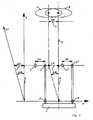
- a turntable 1is arranged on a 3D coordinate measuring machine (not shown).
- a physical axis of rotation 5 of the turntable 1is oriented approximately parallel to a movement axis of the 3D coordinate measuring machine, namely to the Z-axis.
- a Einmesskugel 2is shown in two 180 ° offset turntable positions 2, 2 '. In the upper part of Fig. 1, a circle 8 is shown, which describes a ball center of the Einmesskugel 2 when the turntable 1 occupies different angular positions.
- the measuring ball 2When the measuring ball 2 is measured in a position spaced apart from the turntable surface by h, it changes nothing in the measured position of the physical axis of rotation 5 in the coordinate system of the 3D coordinate measuring machine, if this is constructed strictly Cartesian, that is, the angle between the axes (in Fig. 1 in the X and Z axis shown) is exactly 90 °.
- the method according to the inventionmakes use of the effect of the height-dependent rotary axis offset for determining the perpendicularity deviation of that movement axis of the 3D coordinate measuring machine which runs parallel to the turntable axis to the other two axes.
- the turntable axis 5is determined twice, each with a ball 2, 3, which are mounted at different heights on the turntable 1, by measuring the circles 8, 9 described above.
- the upper circle 9is projected onto the lower circle 8. This results in a radial distance .DELTA.X of the two circle centers in the X direction of the coordinate system of the 3D coordinate measuring machine or .DELTA.Y in the Y direction (not shown).
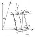
- the physical axis of rotation 5 of the turntable 1is not exactly parallel to one of the axes of movement of the 3D coordinate measuring machine, in the present case to the Z axis.
- the Einmesskugeln 2, 3 with respect to this axis of movementdifferent heights.
- the ball 2is measured in the 180 ° position, for example with a slightly too large X-coordinate. This leads to a slight tilting of the circle 8 and to an elliptical distortion.
Landscapes
- Physics & Mathematics (AREA)
- General Physics & Mathematics (AREA)
- A Measuring Device Byusing Mechanical Method (AREA)
Description
Translated fromGermanDie Erfindung betrifft ein Verfahren zur Bestimmung von Rechtwinkligkeitsabweichungen zwischen der Z-Bewegungsachse eines 3D-Koordinatenmessgerätes gegenüber den beiden anderen Bewegungsachsen sowie ein Verfahren zur Korrektur dieser Rechtwinkligkeitsabweichungen eines 3D-Koordinatenmessgerätes.The invention relates to a method for determining perpendicularity deviations between the Z-axis movement of a 3D coordinate measuring machine relative to the other two axes of movement and a method for correcting these perpendicularity deviations of a 3D coordinate measuring machine.
Gemäß dem Stand der Technik werden in der Koordinatenmesstechnik häufig Drehtische in Verbindung mit 3D-Koordinatenmessgeräten eingesetzt, um die Zugänglichkeit des Werkstückes für das 3D-Koordinatenmessgerät zu verbessern. Dabei wird ein Drehtisch ortsfest im Koordinatensystem des 3D-Koordinatenmessgerätes platziert. Auf dem Drehtisch wird ein zu messendes Werkstück montiert. Wenn die Lage und Orientierung der Drehachse des Drehtisches im Koordinatensystem des Koordinatenmessgerätes der Steuerung des 3D-Koordinatenmessgerätes bekannt sind, lassen sich die verschiedenen Merkmale des Werkstückes sehr elegant in einem werkstückbezogenen Koordinatensystem messen, das von der Winkelstellung des Drehtisches unabhängig ist.According to the state of the art, rotary tables are frequently used in coordinate measuring technology in conjunction with 3D coordinate measuring machines in order to improve the accessibility of the workpiece for the 3D coordinate measuring machine. In this case, a turntable is placed stationary in the coordinate system of the 3D coordinate measuring machine. A workpiece to be measured is mounted on the turntable. If the position and orientation of the axis of rotation of the turntable in the coordinate system of the coordinate measuring machine of the control of the 3D coordinate measuring machine are known, the various features of the workpiece can be very elegant measure in a workpiece-related coordinate system, which is independent of the angular position of the turntable.
Nach dem Stand der Technik werden die Lage und Orientierung einer Drehachse eines Drehtisches auf einer Koordinatenmessmaschine dadurch bestimmt, dass eine auf dem Drehtisch von seiner Drehachse in radialer Richtung beabstandet montierte Kugel in verschiedenen Winkelstellungen des Drehtisches von der Koordinatenmessmaschine gemessen wird. Dabei liegen die Kugelmittelpunkte auf einer angenommenen Kreisbahn, die eine Ebene aufspannt, deren Ebenennormale im Kreismittelpunkt mit der Drehachse des Drehtisches zusammenfällt. Mit den in der Koordinatenmesstechnik üblichen und vorhandenen Methoden wird diese Ebenennormale als Drehachse des Drehtisches im Koordinatensystem des 3D-Koordinatenmessgerätes verankert und aus ihr ein Drehtischkoordinatensystem gebildet, das fest mit der Drehtischoberfläche verbunden ist.According to the prior art, the position and orientation of a rotation axis of a turntable on a coordinate measuring machine are determined by measuring a ball mounted on the turntable from its axis of rotation in the radial direction in different angular positions of the turntable from the coordinate measuring machine. The ball centers lie on an assumed circular path, which spans a plane whose plane normal coincides in the center of the circle with the axis of rotation of the turntable. With the usual in coordinate measuring and existing methods this level normal is anchored as the axis of rotation of the turntable in the coordinate system of the 3D coordinate measuring machine and formed from it a turntable coordinate system, which is firmly connected to the turntable surface.
Diesen Vorgang bezeichnet man als das so genannte "Einmessen des Drehtisches".This process is known as the so-called "measuring the turntable".
Dabei spielt die Rechtwinkligkeit der linearen Achsen des Koordinatenmessgerätes zueinander eine wichtige Rolle. Insbesondere die Rechtwinkligkeit derjenigen Achse des Koordinatenmessgerätes, die mit der Drehachse des Drehtisches den kleinsten Winkel einschließt (im Folgenden Z-Achse genannt) gegenüber den beiden anderen Achsen des Koordinatenmessgerätes, wirkt sich kritisch auf die Drehachsenbestimmung des Drehtisches aus. Der oben erwähnte Kugelkreis wandert parallel zu seiner Kreisebene, wenn die Kugeln in unterschiedlichen Höhen bezogen auf die Z-Achse gemessen werden und die Winkel zwischen der Z-Achse des Koordinatenmessgerätes und den beiden anderen Achsen nicht exakt 90° betragen. Damit ist die Lage der Drehachse des Drehtisches abhängig von der Höhe, in der die Kugeln über der Tischplatte gemessen werden, wodurch die Eindeutigkeit der Drehachse des Drehtisches verloren geht. Beim Messen eines Werkstückes müsste, abhängig von der Höhe des Messpunktes über der Drehtischplatte, für die anstehenden Koordinatentransformationen für jeden einzelnen Messpunkt jeweils eine andere Drehtischachsenlage zugrunde gelegt werden. Dies ist jedoch überhaupt nicht praktikabel.The perpendicularity of the linear axes of the coordinate measuring machine to each other plays an important role. In particular, the perpendicularity of that axis of the coordinate measuring machine, which includes the smallest angle with the axis of rotation of the rotary table (referred to below as the Z axis) with respect to the other two axes of the coordinate measuring machine, has a critical effect on the rotary axis determination of the rotary table. The above-mentioned sphere circle moves parallel to its circle plane when the balls are measured at different heights with respect to the Z axis and the angles between the Z axis of the CMM and the other two axes are not exactly 90 °. Thus, the position of the axis of rotation of the turntable is dependent on the height at which the balls are measured over the table top, whereby the uniqueness of the axis of rotation of the turntable is lost. When measuring a workpiece, depending on the height of the measuring point above the turntable plate, a different turntable axis position would have to be used for the pending coordinate transformations for each individual measuring point. However, this is not practical at all.
Das der Erfindung zugrunde liegende technische Problem besteht darin, den Nachteil von Rechtwinkligkeitsabweichungen der Z-Achse des Koordinatenmessgerätes gegenüber den anderen Achsen zu vermeiden, indem bei dem Vorgang des Einmessens des Drehtisches die Rechtwinkligkeitsabweichung zwischen den linearen Bewegungsachsen eines 3D-Koordinatenmessgerätes ermittelt wird, sowie ein Verfahren zur Korrektur der Rechtwinkligkeitsabweichung zwischen den linearen Bewegungsachsen eines 3D-Koordinatenmessgerätes anzugeben.The technical problem underlying the invention is to avoid the disadvantage of perpendicularity deviations of the Z-axis of the coordinate measuring machine relative to the other axes by the perpendicularity deviation between the linear axes of motion of a 3D coordinate measuring machine is determined in the process of the calibration of the turntable, and a To specify a method for correcting the perpendicularity deviation between the linear axes of motion of a 3D coordinate measuring machine.
Dieses technische Problem wird durch ein Verfahren mit den Merkmalen gemäß Anspruch 1 sowie durch ein Verfahren mit den Merkmalen gemäß Anspruch 4 gelöst.This technical problem is solved by a method having the features according to
Gemäß der Erfindung weist das Verfahren zur Bestimmung von Rechtwinkligkeitsabweichungen zwischen der Z-Bewegungsachse eines 3D-Koordinatenmessgerätes gegenüber den beiden anderen Bewegungsachsen folgende Verfahrensschritte auf:
- Messen eines ersten Prüfkörpers in verschiedenen Winkelstellungen eines Drehtisches, dessen Drehachse ungefähr parallel zur Z-Bewegungsachse des 3D-Koordinatenmessgerätes orientiert ist, wobei der Prüfkörper mit einem radialen Abstand zur Drehachse und mit einem ersten Abstand zur Drehtischoberfläche auf dem Drehtisch angeordnet ist,
- Auswerten eines ersten, unteren Kreises, der durch einen Bezugspunkt des Prüfkörpers in verschiedenen Winkelstellungen des Drehtisches beschrieben wird,
- Messen des ersten Prüfkörpers oder eines zweiten Prüfkörpers, der ebenfalls mit einem radialen Abstand zur Drehachse des Drehtisches und in einem zweiten Abstand zur Drehtischoberfläche auf dem Drehtisch angeordnet ist, in verschiedenen Winkelstellungen des Drehtisches,
- Auswerten eines zweiten, oberen Kreises, der durch einen Bezugspunkt des Prüfkörpers in dem zweiten Abstand in den verschiedenen Winkelstellungen des Drehtisches beschrieben wird,
- Projizieren des oberen Kreises auf den unteren Kreis,
- Bestimmen der Rechtwinkligkeitsabweichung der Z-Bewegungsachse gegenüber den beiden anderen Bewegungsachsen des 3D-Koordinatenmessgerätes aus der Höhendifferenz zwischen den Abständen der Prüfkörper über der Drehtischoberfläche und aus den Abständen der Kreismittelpunkte der beiden Kreise in Richtung der beiden anderen Bewegungsachsen des 3D-Koordinatenmessgerätes nach der Projektion.
- Measuring a first test specimen in different angular positions of a turntable, the axis of rotation of which is oriented approximately parallel to the Z axis of movement of the 3D coordinate measuring machine, the test specimen being arranged at a radial distance from the axis of rotation and at a first distance to the turntable surface on the turntable,
- Evaluating a first, lower circle, which is described by a reference point of the test specimen in different angular positions of the turntable,
- Measuring the first specimen or a second specimen, which is also arranged at a radial distance from the axis of rotation of the turntable and at a second distance to the turntable surface on the turntable, in different angular positions of the turntable,
- Evaluating a second, upper circle, which is described by a reference point of the test specimen in the second distance in the different angular positions of the turntable,
- Projecting the upper circle onto the lower circle,
- Determining the perpendicularity deviation of the Z-movement axis relative to the other two axes of movement of the 3D coordinate measuring machine from the height difference between the distances between the test specimens on the turntable surface and from the distances of the circle centers of the two circles in the direction of the other two axes of movement of the 3D coordinate measuring machine after the projection.
Durch das erfindungsgemäße Verfahren ist es möglich, die Bestimmung der Rechtwinkligkeitsabweichung zwischen den Bewegungsachsen eines 3D-Koordinatenmessgerätes zusammen mit dem Einmessvorgang des Drehtisches zu bestimmen. Das Messen des ersten Prüfkörpers in verschiedenen Winkelstellungen des Drehtisches ist nämlich Teil des Einmessvorganges des Drehtisches, bei dem, wie oben im Stand der Technik beschrieben, die Kugel in verschiedenen Winkelstellungen des Drehtisches in der Koordinatenmessmaschine gemessen wird und hieraus, wie oben beschrieben, die Drehachse des Drehtisches bestimmt wird.The inventive method makes it possible to determine the determination of the perpendicularity deviation between the axes of movement of a 3D coordinate measuring machine together with the calibration process of the turntable. The Measuring the first specimen in different angular positions of the turntable is namely part of the Einmessvorganges the turntable, in which, as described above in the prior art, the ball is measured in different angular positions of the turntable in the coordinate measuring machine and, as described above, the axis of rotation of the Turntable is determined.
Gemäß dem erfindungsgemäßen Verfahren wird der erste Prüfkörper oder ein zweiter Prüfkörper zusätzlich in einem anderen Abstand zum Drehtisch ebenfalls in verschiedenen Winkelstellungen des Drehtisches gemessen. Handelt es sich bei dem Prüfkörper um eine Kugel, wird wiederum die Kreisbahn, auf der die Kugelmittelpunkte liegen, bestimmt.According to the method of the invention, the first specimen or a second specimen is also measured at different distances from the turntable also in different angular positions of the turntable. If the test specimen is a sphere, in turn the circular path on which the sphere centers lie is determined.
Der radiale Abstand der Mittelpunkte der beiden Kreise wird bestimmt, wodurch wiederum die Rechtwinkligkeitsabweichung des 3D-Koordinatenmessgerätes bestimmt werden kann, da die Höhendifferenz zwischen den Prüfkörpern zwischen der ersten Messung und der zweiten Messung bekannt ist.The radial distance of the centers of the two circles is determined, which in turn allows the perpendicularity deviation of the 3D coordinate measuring machine to be determined, since the height difference between the test pieces between the first measurement and the second measurement is known.
Die Verfahrensschritte des Messens und des Auswertens des oben beschriebenen Verfahrens können in geänderter Reihenfolge durchgeführt werden. Beispielsweise ist es möglich, erst die Prüfkörper in den beiden unterschiedlichen Abständen vom Drehtisch zu messen und anschließend die Auswertung durchzuführen.The method steps of measuring and evaluating the method described above can be carried out in a changed order. For example, it is possible to first measure the specimens in the two different distances from the turntable and then perform the evaluation.
Gemäß einer besonders bevorzugten Ausführungsform der Erfindung wird als Prüfkörper eine Kugel verwendet, deren Kugelmittelpunkt jeweils in den verschiedenen Winkelstellungen bestimmt wird.According to a particularly preferred embodiment of the invention, a ball is used as a test object, the ball center is determined in each case in the different angular positions.
Die Bestimmung der räumlichen Lage des Kreises, den die auf dem Drehtisch montierte Kugel beschreibt, erfolgt vorteilhaft mit den folgenden Schritten:
- Messung der Kugel mit mindestens vier Antastpunkten in mindestens drei Winkelstellungen des Drehtisches,
- Berechnen der Kugelmittelpunkte,
- Berechnen einer besteingepassten Ebene durch die Kugelmittelpunkte,
- Projizieren der Kugelmittelpunkte in die berechnete Ebene,
- Berechnen des Kreises, den die projizierten Kugelmittelpunkte in der berechneten Ebene beschreiben,
- Berechnen der Lage des Kreismittelpunktes des berechneten Kreises im Koordinatensystem des Koordinatenmessgerätes,
- Berechnen der Orientierung der Ebenennormalen der berechneten Ebene im Koordinatensystem des Koordinatenmessgerätes.
- Measuring the ball with at least four probing points in at least three angular positions of the turntable,
- Calculating the sphere centers,
- Calculating a best fitted plane through the sphere centers,
- Projecting the sphere centers into the calculated plane,
- Calculating the circle that the projected sphere centers describe in the calculated plane,
- Calculating the position of the circle center of the calculated circle in the coordinate system of the coordinate measuring machine,
- Calculating the orientation of the plane normal of the calculated plane in the coordinate system of the coordinate measuring machine.
Durch die Bestimmung der Rechtwinkligkeitsabweichung gemäß dem erfindungsgemäßen Verfahren ist es möglich, mit einem Teil der beim Einmessen des Drehtisches ohnehin bestimmten Messwerte die Rechtwinkligkeitsabweichung des Koordinatenmessgerätes mit zu bestimmen.By determining the perpendicularity deviation according to the method according to the invention, it is possible to use a part of the measured values, which in any case are determined during the measuring of the turntable, to also determine the perpendicularity deviation of the coordinate measuring machine.
Vorteilhaft werden mit den Werten der Rechtwinkligkeitsabweichung die Messwerte der Prüfkörper nachträglich korrigiert.Advantageously, the measured values of the test specimens are subsequently corrected with the values of the perpendicularity deviation.
Gemäß einer weiteren vorteilhaften Ausführungsform des erfindungsgemäßen Verfahrens wird die Lage des Drehtisches aus den korrigierten Messwerten bestimmt, um die Messgenauigkeit zu erhöhen.According to a further advantageous embodiment of the method according to the invention, the position of the turntable is determined from the corrected measured values in order to increase the measuring accuracy.
Gemäß einer weiteren vorteilhaften Ausführungsform des erfindungsgemäßen Verfahrens werden die ermittelten Rechtwinkligkeitsabweichungen zur Korrektur von durchzuführenden Antastungen herangezogen.According to a further advantageous embodiment of the method according to the invention, the ascertained perpendicularity deviations become used for the correction of probing to be performed.
Weitere Merkmale und Vorteile der Erfindung ergeben sich anhand der zugehörigen Zeichnung, in der mehrere Ausführungsbeispiele des erfindungsgemäßen Verfahrens nur beispielhaft dargestellt sind. In der Zeichnung zeigen:
- Fig. 1
- die Bestimmung der Rechtwinkligkeitsabweichung eines Koordinatenmessgerätes beim Einmessen eines Drehtisches mit einer ungefähr parallel zu einer der Bewegungsachsen des 3D-Koordinatenmessgerätes angeordneten Drehachse;
- Fig. 2
- Bestimmung der Rechtwinkligkeitsabweichung mit einem Drehtisch, dessen Drehachse nicht exakt parallel zu einer der Bewegungsachsen des 3D-Koordinatenmessgerätes ausgerichtet ist.
- Fig. 1
- the determination of the perpendicularity deviation of a coordinate measuring machine when measuring a turntable with an approximately parallel to one of the axes of movement of the 3D coordinate measuring machine arranged axis of rotation;
- Fig. 2
- Determination of the perpendicularity deviation with a turntable whose axis of rotation is not aligned exactly parallel to one of the axes of motion of the 3D coordinate measuring machine.
Gemäß Fig. 1 ist ein Drehtisch 1 auf einem 3D-Koordinatenmessgerät (nicht dargestellt) angeordnet. Eine physikalische Drehachse 5 des Drehtisches 1 ist ungefähr parallel zu einer Bewegungsachse des 3D-Koordinatenmessgerätes orientiert, nämlich zu der Z-Achse. Eine Einmesskugel 2 ist in zwei 180° versetzten Drehtischstellungen 2, 2' dargestellt. Im oberen Teil der Fig. 1 ist ein Kreis 8 dargestellt, den ein Kugelmittelpunkt der Einmesskugel 2 beschreibt, wenn der Drehtisch 1 verschiedene Winkelstellungen einnimmt.1, a
Wenn die Einmesskugel 2 in einer um h von der Drehtischoberfläche beabstandeten Lage gemessen wird, ändert sich nichts an der gemessenen Lage der physikalischen Drehachse 5 im Koordinatensystem des 3D-Koordinatenmessgerätes, sofern dieses streng kartesisch aufgebaut ist, das heißt, der Winkel zwischen den Achsen (in Fig. 1 in X- und Z-Achse dargestellt) exakt 90° beträgt.When the measuring
In der Praxis kommen durchaus Abweichungen von der Rechtwinkligkeit von mehreren Winkelsekunden vor, die dann dazu führen, dass die beiden Kreise 8 (gemessen mit der Kugel 2) und 9 (gemessen mit einer Kugel 3) nicht zu der gleichen gemessenen Lage der physikalischen Drehachse führen, sondern scheinbar zwei Drehachsen mit einem seitlichen Abstand von ΔX ergeben. Dies führt bei Messungen eines Werkstückes auf dem Drehtisch 1 unter Ausnutzung eines, mit Hilfe der, aus dem Kreis 8 erzeugten, gemessenen Drehachse, mitdrehenden Koordinatensystems zu Messfehlern, die mit wachsendem Abstand der Messpunkte von der Ebene des Kreises 8 immer größer werden.In practice, deviations from the perpendicularity of several angular seconds occur, which then lead to the fact that the two circles 8 (measured with the ball 2) and 9 (measured with a ball 3) do not lead to the same measured position of the physical axis of rotation , but apparently two axes of rotation with a lateral distance of .DELTA.X result. This results in measurements of a workpiece on the
Insbesondere bei 3D-Koordinatenmessgeräten, die in der Fertigung stehen und dort erheblichen Temperaturschwankungen ausgesetzt sind, ist die Stabilität der Rechtwinkligkeit der Verfahrachsen nicht unter allen Umständen gewährleistet.Especially with 3D coordinate measuring machines that are in production and there are exposed to significant temperature fluctuations, the stability of the perpendicularity of the axes is not guaranteed under all circumstances.
Das erfindungsgemäße Verfahren nutzt den Effekt des höhenabhängigen Drehachsenversatzes zur Bestimmung der Rechtwinkligkeitsabweichung derjenigen Bewegungsachse des 3D-Koordinatenmessgerätes, die parallel zur Drehtischachse verläuft, zu den beiden anderen Achsen aus.The method according to the invention makes use of the effect of the height-dependent rotary axis offset for determining the perpendicularity deviation of that movement axis of the 3D coordinate measuring machine which runs parallel to the turntable axis to the other two axes.
Bei dem erfindungsgemäßen Verfahren wird die Drehtischachse 5 zweimal mit je einer Kugel 2, 3, die in unterschiedlichen Höhen auf dem Drehtisch 1 montiert sind, durch Messen der oben beschriebenen Kreise 8, 9 bestimmt. Der obere Kreis 9 wird auf den unteren Kreis 8 projiziert. Dabei ergibt sich ein radialer Abstand ΔX der beiden Kreismittelpunkte in X-Richtung des Koordinatensystems des 3D-Koordinatenmessgerätes beziehungsweise ΔY in Y-Richtung (nicht dargestellt).In the method according to the invention, the
Aus diesem Abstand und der Höhendifferenz h der Kugeln über der Drehtischplatte lässt sich die Rechtwinkligkeitsabweichung Δα über die Formeln
- Gl. 1

- Gl. 2


- Eq. 1
- Eq. 2
Gemäß Fig. 2 liegt die physikalische Drehachse 5 des Drehtisches 1 nicht exakt parallel zu einer der Bewegungsachsen des 3D-Koordinatenmessgerätes, im vorliegenden Fall zur Z-Achse. In diesem Fall durchlaufen die Einmesskugeln 2, 3 bezüglich dieser Bewegungsachse verschiedene Höhen. Dadurch wird die Kugel 2 in der 180°-Stellung beispielsweise mit einer etwas zu großen X-Koordinate gemessen. Dies führt zu einem leichten Kippen des Kreises 8 sowie zu einer elliptischen Verzerrung.2, the physical axis of
Beide Effekte treffen in gleichem Maße auch auf die obere Kugel 3 zu, so dass im Ergebnis die Winkelberechnung korrekt bleibt, wenn sie wie in Gleichung 1 oder Gleichung 2 durchgeführt wird und die beiden Ellipsen weiterhin als Kreise behandelt werden. Die Abstände ΔX und ΔY werden jetzt in der Kreisebene der unteren Kugel 2 nach Projektion des oberen Kreises 9 auf den unteren Kreis 8 bestimmt. Wie in Fig. 2 dargestellt, wird durch die Rechtwinkligkeitsabweichung des Koordinatenmessgerätes die Lage 4, 4' der Prüfkörper 3, 3' erfasst. Der durch die Lagebestimmung der Kugeln 3, 3' in der Lage 4, 4' ermittelte Kreis 9 und dessen Mittelpunkt 10 hat einen radialen Abstand ΔX von dem tatsächlichen Mittelpunkt 11, der auf der physikalischen Drehachse 5 liegt.Both effects apply equally to the
- 11
- Drehtischturntable
- 22
- Prüfkörperspecimen
- 3, 3'3, 3 '
- Prüfkörperspecimen
- 4, 4'4, 4 '
- Lagelocation
- 55
- Drehachseaxis of rotation
- 77
- Abstand ΔXDistance ΔX
- 88th
- Kreiscircle
- 99
- Kreiscircle
- 1010
- MittelpunktFocus
- 1111
- Mittelpunkt in Höhe hMidpoint in height h
Claims (6)
- A method of determining the rectangularity deviation between the Z-movement axis of a 3D co-ordinate-measuring machine with respect to the two other movement axes having the following method steps:a) measuring a first test body (2) in different angular settings of a turntable (1), the axis of rotation (5) of which is orientated substantially parallel to the Z-movement axis of the 3D co-ordinate-measuring machine, wherein the test body (2) is arranged on the turntable (1) at a radial distance from the axis of rotation (5) and at a first distance from the surface of the turntable,b) evaluating a first, lower circle (8) which is described by a reference point of the test body (2) in the different angular settings of the turntable (1),c) measuring the first test body (2) or a second test body (3) which is likewise arranged on the turntable (1) at a radial distance from the axis of rotation (5) of the turntable (1) and at a second distance from the surface of the turntable, in different angular settings of the turntable (1),d) evaluating a second, upper circle (9) which is described by a reference point of the test body (2, 3) at the second distance in the different angular settings of the turntable (1),e) projecting the upper circle (9) onto the lower circle (8), andf) determining the rectangularity deviation of the Z-movement axis with respect to the two other movement axes of the 3D co-ordinate-measuring machine from the difference in height(h) between the distances of the test bodies (2, 3) above the surface of the turntable and from the distances(ΔX andΔY) of the centres of the two circles (8, 9) in the direction of the two other movement axes of the 3D co-ordinate-measuring machine after the projection.
- A method according to Claim 1, in which the method steps b) and c) are carried out in a reversed sequence.
- A method according to any one of Claims 1 to 2, wherein a sphere is used as the test body (2, 3).
- A method of correcting the rectangularity deviation between the Z-movement axis of a 3D co-ordinate-measuring machine with respect to the two other movement axes, in which the rectangularity deviation is determined by a method according to any one of Claims 1 to 3, and the measurement values of the test bodies (2, 3) are subsequently corrected with the rectangularity deviations determined.
- A method according to Claim 4, wherein the position of the axis of rotation (5) is determined from the corrected measurement values.
- A method according to Claim 4, wherein the rectangularity deviations determined are used to correct sensings to be carried out.
Priority Applications (2)
| Application Number | Priority Date | Filing Date | Title |
|---|---|---|---|
| EP20050020192EP1764579B1 (en) | 2005-09-16 | 2005-09-16 | Method to Determine the Orthogonality of the Axes of a Coordinate Measuring Machine |
| DE200550002357DE502005002357D1 (en) | 2005-09-16 | 2005-09-16 | Method for determining the squareness between the axes of a 3D coordinate measuring machine |
Applications Claiming Priority (1)
| Application Number | Priority Date | Filing Date | Title |
|---|---|---|---|
| EP20050020192EP1764579B1 (en) | 2005-09-16 | 2005-09-16 | Method to Determine the Orthogonality of the Axes of a Coordinate Measuring Machine |
Publications (2)
| Publication Number | Publication Date |
|---|---|
| EP1764579A1 EP1764579A1 (en) | 2007-03-21 |
| EP1764579B1true EP1764579B1 (en) | 2007-12-26 |
Family
ID=35478849
Family Applications (1)
| Application Number | Title | Priority Date | Filing Date |
|---|---|---|---|
| EP20050020192Expired - LifetimeEP1764579B1 (en) | 2005-09-16 | 2005-09-16 | Method to Determine the Orthogonality of the Axes of a Coordinate Measuring Machine |
Country Status (2)
| Country | Link |
|---|---|
| EP (1) | EP1764579B1 (en) |
| DE (1) | DE502005002357D1 (en) |
Cited By (25)
| Publication number | Priority date | Publication date | Assignee | Title |
|---|---|---|---|---|
| US8001697B2 (en) | 2010-01-20 | 2011-08-23 | Faro Technologies, Inc. | Counter balance for coordinate measurement device |
| US8284407B2 (en) | 2010-01-20 | 2012-10-09 | Faro Technologies, Inc. | Coordinate measuring machine having an illuminated probe end and method of operation |
| US8533967B2 (en) | 2010-01-20 | 2013-09-17 | Faro Technologies, Inc. | Coordinate measurement machines with removable accessories |
| US8615893B2 (en) | 2010-01-20 | 2013-12-31 | Faro Technologies, Inc. | Portable articulated arm coordinate measuring machine having integrated software controls |
| US8630314B2 (en) | 2010-01-11 | 2014-01-14 | Faro Technologies, Inc. | Method and apparatus for synchronizing measurements taken by multiple metrology devices |
| US8638446B2 (en) | 2010-01-20 | 2014-01-28 | Faro Technologies, Inc. | Laser scanner or laser tracker having a projector |
| US8677643B2 (en) | 2010-01-20 | 2014-03-25 | Faro Technologies, Inc. | Coordinate measurement machines with removable accessories |
| US8832954B2 (en) | 2010-01-20 | 2014-09-16 | Faro Technologies, Inc. | Coordinate measurement machines with removable accessories |
| US8875409B2 (en) | 2010-01-20 | 2014-11-04 | Faro Technologies, Inc. | Coordinate measurement machines with removable accessories |
| US8898919B2 (en) | 2010-01-20 | 2014-12-02 | Faro Technologies, Inc. | Coordinate measurement machine with distance meter used to establish frame of reference |
| US8997362B2 (en) | 2012-07-17 | 2015-04-07 | Faro Technologies, Inc. | Portable articulated arm coordinate measuring machine with optical communications bus |
| US9074883B2 (en) | 2009-03-25 | 2015-07-07 | Faro Technologies, Inc. | Device for optically scanning and measuring an environment |
| US9113023B2 (en) | 2009-11-20 | 2015-08-18 | Faro Technologies, Inc. | Three-dimensional scanner with spectroscopic energy detector |
| US9168654B2 (en) | 2010-11-16 | 2015-10-27 | Faro Technologies, Inc. | Coordinate measuring machines with dual layer arm |
| US9210288B2 (en) | 2009-11-20 | 2015-12-08 | Faro Technologies, Inc. | Three-dimensional scanner with dichroic beam splitters to capture a variety of signals |
| USRE45854E1 (en) | 2006-07-03 | 2016-01-19 | Faro Technologies, Inc. | Method and an apparatus for capturing three-dimensional data of an area of space |
| US9329271B2 (en) | 2010-05-10 | 2016-05-03 | Faro Technologies, Inc. | Method for optically scanning and measuring an environment |
| US9372265B2 (en) | 2012-10-05 | 2016-06-21 | Faro Technologies, Inc. | Intermediate two-dimensional scanning with a three-dimensional scanner to speed registration |
| US9417316B2 (en) | 2009-11-20 | 2016-08-16 | Faro Technologies, Inc. | Device for optically scanning and measuring an environment |
| US9417056B2 (en) | 2012-01-25 | 2016-08-16 | Faro Technologies, Inc. | Device for optically scanning and measuring an environment |
| US9513107B2 (en) | 2012-10-05 | 2016-12-06 | Faro Technologies, Inc. | Registration calculation between three-dimensional (3D) scans based on two-dimensional (2D) scan data from a 3D scanner |
| US9529083B2 (en) | 2009-11-20 | 2016-12-27 | Faro Technologies, Inc. | Three-dimensional scanner with enhanced spectroscopic energy detector |
| US9551575B2 (en) | 2009-03-25 | 2017-01-24 | Faro Technologies, Inc. | Laser scanner having a multi-color light source and real-time color receiver |
| US10175037B2 (en) | 2015-12-27 | 2019-01-08 | Faro Technologies, Inc. | 3-D measuring device with battery pack |
| CN110421393A (en)* | 2019-05-29 | 2019-11-08 | 陕西飞机工业(集团)有限公司 | A kind of method of the quick secondary centering of numerical control milling workpiece |
Families Citing this family (8)
| Publication number | Priority date | Publication date | Assignee | Title |
|---|---|---|---|---|
| US9628775B2 (en) | 2010-01-20 | 2017-04-18 | Faro Technologies, Inc. | Articulated arm coordinate measurement machine having a 2D camera and method of obtaining 3D representations |
| US9607239B2 (en) | 2010-01-20 | 2017-03-28 | Faro Technologies, Inc. | Articulated arm coordinate measurement machine having a 2D camera and method of obtaining 3D representations |
| US10067231B2 (en) | 2012-10-05 | 2018-09-04 | Faro Technologies, Inc. | Registration calculation of three-dimensional scanner data performed between scans based on measurements by two-dimensional scanner |
| DE102013204581A1 (en)* | 2013-03-15 | 2014-09-18 | Carl Zeiss Industrielle Messtechnik Gmbh | Method for correcting an angular deviation in the operation of a coordinate measuring machine |
| CN107883979B (en)* | 2016-09-30 | 2021-03-12 | 北京诺亦腾科技有限公司 | Method and system for unifying inertial sensor coordinate system and reference coordinate system |
| DE102017220876B4 (en)* | 2017-11-22 | 2020-12-24 | Ford Global Technologies, Llc | Method and device for determining position and orientation |
| CN108151672B (en)* | 2017-12-28 | 2023-01-06 | 华中科技大学 | Shaft shape tolerance measuring instrument based on projection imaging |
| CN115355861B (en)* | 2022-10-19 | 2022-12-30 | 中国科学院长春光学精密机械与物理研究所 | Axis Alignment Method in Measurement of Rotary Parts |
Family Cites Families (4)
| Publication number | Priority date | Publication date | Assignee | Title |
|---|---|---|---|---|
| DE2940633C2 (en)* | 1979-10-06 | 1986-01-02 | Ernst Leitz Wetzlar Gmbh, 6330 Wetzlar | Method for determining the axis of rotation of a rotary table in multi-coordinate measuring devices |
| DE19815098B4 (en)* | 1998-04-03 | 2005-07-14 | Leitz Messtechnik Gmbh | Method for measuring turntable deviations |
| JP2001330428A (en)* | 2000-05-23 | 2001-11-30 | Natl Inst Of Advanced Industrial Science & Technology Meti | Method for evaluating measurement error of three-dimensional measuring machine and gauge for three-dimensional measuring machine |
| DE10122080A1 (en)* | 2001-05-07 | 2002-11-14 | Carl Zeiss 3D Metrology Servic | Method for determining properties of a coordinate measuring machine and test object therefor |
- 2005
- 2005-09-16EPEP20050020192patent/EP1764579B1/ennot_activeExpired - Lifetime
- 2005-09-16DEDE200550002357patent/DE502005002357D1/ennot_activeExpired - Lifetime
Cited By (37)
| Publication number | Priority date | Publication date | Assignee | Title |
|---|---|---|---|---|
| USRE45854E1 (en) | 2006-07-03 | 2016-01-19 | Faro Technologies, Inc. | Method and an apparatus for capturing three-dimensional data of an area of space |
| US9074883B2 (en) | 2009-03-25 | 2015-07-07 | Faro Technologies, Inc. | Device for optically scanning and measuring an environment |
| US9551575B2 (en) | 2009-03-25 | 2017-01-24 | Faro Technologies, Inc. | Laser scanner having a multi-color light source and real-time color receiver |
| US9529083B2 (en) | 2009-11-20 | 2016-12-27 | Faro Technologies, Inc. | Three-dimensional scanner with enhanced spectroscopic energy detector |
| US9417316B2 (en) | 2009-11-20 | 2016-08-16 | Faro Technologies, Inc. | Device for optically scanning and measuring an environment |
| US9210288B2 (en) | 2009-11-20 | 2015-12-08 | Faro Technologies, Inc. | Three-dimensional scanner with dichroic beam splitters to capture a variety of signals |
| US9113023B2 (en) | 2009-11-20 | 2015-08-18 | Faro Technologies, Inc. | Three-dimensional scanner with spectroscopic energy detector |
| US8630314B2 (en) | 2010-01-11 | 2014-01-14 | Faro Technologies, Inc. | Method and apparatus for synchronizing measurements taken by multiple metrology devices |
| US8898919B2 (en) | 2010-01-20 | 2014-12-02 | Faro Technologies, Inc. | Coordinate measurement machine with distance meter used to establish frame of reference |
| US8028432B2 (en) | 2010-01-20 | 2011-10-04 | Faro Technologies, Inc. | Mounting device for a coordinate measuring machine |
| US8638446B2 (en) | 2010-01-20 | 2014-01-28 | Faro Technologies, Inc. | Laser scanner or laser tracker having a projector |
| US8942940B2 (en) | 2010-01-20 | 2015-01-27 | Faro Technologies, Inc. | Portable articulated arm coordinate measuring machine and integrated electronic data processing system |
| US8683709B2 (en) | 2010-01-20 | 2014-04-01 | Faro Technologies, Inc. | Portable articulated arm coordinate measuring machine with multi-bus arm technology |
| US8763266B2 (en) | 2010-01-20 | 2014-07-01 | Faro Technologies, Inc. | Coordinate measurement device |
| US8832954B2 (en) | 2010-01-20 | 2014-09-16 | Faro Technologies, Inc. | Coordinate measurement machines with removable accessories |
| US8875409B2 (en) | 2010-01-20 | 2014-11-04 | Faro Technologies, Inc. | Coordinate measurement machines with removable accessories |
| US8001697B2 (en) | 2010-01-20 | 2011-08-23 | Faro Technologies, Inc. | Counter balance for coordinate measurement device |
| US8276286B2 (en) | 2010-01-20 | 2012-10-02 | Faro Technologies, Inc. | Display for coordinate measuring machine |
| US8677643B2 (en) | 2010-01-20 | 2014-03-25 | Faro Technologies, Inc. | Coordinate measurement machines with removable accessories |
| US9009000B2 (en) | 2010-01-20 | 2015-04-14 | Faro Technologies, Inc. | Method for evaluating mounting stability of articulated arm coordinate measurement machine using inclinometers |
| US8601702B2 (en) | 2010-01-20 | 2013-12-10 | Faro Technologies, Inc. | Display for coordinate measuring machine |
| US8537374B2 (en) | 2010-01-20 | 2013-09-17 | Faro Technologies, Inc. | Coordinate measuring machine having an illuminated probe end and method of operation |
| US8615893B2 (en) | 2010-01-20 | 2013-12-31 | Faro Technologies, Inc. | Portable articulated arm coordinate measuring machine having integrated software controls |
| US8533967B2 (en) | 2010-01-20 | 2013-09-17 | Faro Technologies, Inc. | Coordinate measurement machines with removable accessories |
| US8284407B2 (en) | 2010-01-20 | 2012-10-09 | Faro Technologies, Inc. | Coordinate measuring machine having an illuminated probe end and method of operation |
| US8171650B2 (en) | 2010-01-20 | 2012-05-08 | Faro Technologies, Inc. | Intelligent repeatable arm mounting system |
| US9329271B2 (en) | 2010-05-10 | 2016-05-03 | Faro Technologies, Inc. | Method for optically scanning and measuring an environment |
| US9168654B2 (en) | 2010-11-16 | 2015-10-27 | Faro Technologies, Inc. | Coordinate measuring machines with dual layer arm |
| US9417056B2 (en) | 2012-01-25 | 2016-08-16 | Faro Technologies, Inc. | Device for optically scanning and measuring an environment |
| US8997362B2 (en) | 2012-07-17 | 2015-04-07 | Faro Technologies, Inc. | Portable articulated arm coordinate measuring machine with optical communications bus |
| US9513107B2 (en) | 2012-10-05 | 2016-12-06 | Faro Technologies, Inc. | Registration calculation between three-dimensional (3D) scans based on two-dimensional (2D) scan data from a 3D scanner |
| US9372265B2 (en) | 2012-10-05 | 2016-06-21 | Faro Technologies, Inc. | Intermediate two-dimensional scanning with a three-dimensional scanner to speed registration |
| US9618620B2 (en) | 2012-10-05 | 2017-04-11 | Faro Technologies, Inc. | Using depth-camera images to speed registration of three-dimensional scans |
| US11112501B2 (en) | 2012-10-05 | 2021-09-07 | Faro Technologies, Inc. | Using a two-dimensional scanner to speed registration of three-dimensional scan data |
| US10175037B2 (en) | 2015-12-27 | 2019-01-08 | Faro Technologies, Inc. | 3-D measuring device with battery pack |
| CN110421393A (en)* | 2019-05-29 | 2019-11-08 | 陕西飞机工业(集团)有限公司 | A kind of method of the quick secondary centering of numerical control milling workpiece |
| CN110421393B (en)* | 2019-05-29 | 2021-07-16 | 陕西飞机工业(集团)有限公司 | Method for rapidly and secondarily aligning numerical control milling workpiece |
Also Published As
| Publication number | Publication date |
|---|---|
| EP1764579A1 (en) | 2007-03-21 |
| DE502005002357D1 (en) | 2008-02-07 |
Similar Documents
| Publication | Publication Date | Title |
|---|---|---|
| EP1764579B1 (en) | Method to Determine the Orthogonality of the Axes of a Coordinate Measuring Machine | |
| EP2093537B1 (en) | Process and device for the determination of the alignment of two rotatable machine parts | |
| EP2844953B1 (en) | Method for determining the axis of a turntable of a coordinate measuring device | |
| DE112018001621B4 (en) | DETECTOR, SURFACE PROPERTIES MEASURING DEVICE AND ROUNDNESS MEASURING DEVICE | |
| EP2776785B1 (en) | Preparing a tactile probing coordinate measuring machine for operation | |
| WO2014114737A2 (en) | Method and device for determining the geometry of structures by means of computer tomography | |
| EP3255378A1 (en) | Measuring device and method for adjusting the position of a rotation-symmetrical workpiece | |
| EP2834595A1 (en) | Method and device for reducing errors in a turning device during the determination of coordinates of a workpiece or during the machining of a workpiece | |
| WO2015044210A1 (en) | Reduction of errors of a rotating device used during the determination of co-ordinates of a workpiece or during the machining of a workpiece | |
| EP4027104B1 (en) | Method for measuring a numerically controlled machine tool | |
| DE102019208946A1 (en) | Method and device for determining a position of an axis of rotation of a turntable as well as turntable and coordinate measuring machine | |
| DE102015226387A1 (en) | Method for carrying out measurements with a test element in a coordinate measuring machine or a machine tool | |
| EP3314203B1 (en) | Adapter element for assembling a rotational apparatus in the measurement space of a coordinate measuring machine | |
| DE19815098B4 (en) | Method for measuring turntable deviations | |
| EP4102173A1 (en) | Method for positioning a body with an angle scale | |
| DE19907880A1 (en) | Laser measuring method for azimuth, elevation and offset of workpiece spindles in machine tool uses laser measurements for calculating relative angular positions of spindle axes relative to pre-defined reference plane | |
| EP0729005A1 (en) | Measuring device with 6 degrees of freedom | |
| DE3781674T2 (en) | POSITION DETERMINATION METHOD WITHIN THE MEASURING SPACE OF A COORDINATE MEASURING DEVICE AND THE LIKE AND SYSTEM THEREFOR. | |
| DE3320983A1 (en) | TRANSPORTABLE DEVICE FOR CHECKING THE TOOTHED FRAME PROFILE AND TOOTHED FLANGE LINES (TOOTH SLOPES) OF GEARS ON TOOTHING MACHINES OR TOOTHED FRAME GRINDING MACHINES, AND FOR POSITIONING THIS MACHINE AND THE ORGANIZING DEVICE AND THE ORAING MACHINE | |
| DE102015205569B4 (en) | Calibration of a moving part of a coordinate measuring machine or a tactile probe attached to it | |
| DE60032635T2 (en) | METHOD AND DEVICE FOR TESTING TOOLING MACHINES | |
| DE102009020977A1 (en) | Bevel gear normal has calibration reference surface, which is designed such that coordinate system of bevel gear normal is determined, and two geometric elements are configured in form of spheres or sphere portions | |
| DE2938662C2 (en) | ||
| DE102007056773A1 (en) | Method for determining position of virtual bias point relative to coordinate system of industrial robot, involves determining well-known position of virtual bias point for determining position of measuring point in coordinate system | |
| DE102019219973B4 (en) | Method and device for calibrating a sensor and computer program |
Legal Events
| Date | Code | Title | Description |
|---|---|---|---|
| PUAI | Public reference made under article 153(3) epc to a published international application that has entered the european phase | Free format text:ORIGINAL CODE: 0009012 | |
| 17P | Request for examination filed | Effective date:20060202 | |
| AK | Designated contracting states | Kind code of ref document:A1 Designated state(s):AT BE BG CH CY CZ DE DK EE ES FI FR GB GR HU IE IS IT LI LT LU LV MC NL PL PT RO SE SI SK TR | |
| AX | Request for extension of the european patent | Extension state:AL BA HR MK YU | |
| GRAP | Despatch of communication of intention to grant a patent | Free format text:ORIGINAL CODE: EPIDOSNIGR1 | |
| GRAS | Grant fee paid | Free format text:ORIGINAL CODE: EPIDOSNIGR3 | |
| GRAA | (expected) grant | Free format text:ORIGINAL CODE: 0009210 | |
| AKX | Designation fees paid | Designated state(s):CH DE FR GB IT LI | |
| AK | Designated contracting states | Kind code of ref document:B1 Designated state(s):CH DE FR GB IT LI | |
| REG | Reference to a national code | Ref country code:GB Ref legal event code:FG4D Free format text:NOT ENGLISH | |
| REG | Reference to a national code | Ref country code:CH Ref legal event code:EP | |
| REF | Corresponds to: | Ref document number:502005002357 Country of ref document:DE Date of ref document:20080207 Kind code of ref document:P | |
| GBV | Gb: ep patent (uk) treated as always having been void in accordance with gb section 77(7)/1977 [no translation filed] | ||
| EN | Fr: translation not filed | ||
| PLBE | No opposition filed within time limit | Free format text:ORIGINAL CODE: 0009261 | |
| STAA | Information on the status of an ep patent application or granted ep patent | Free format text:STATUS: NO OPPOSITION FILED WITHIN TIME LIMIT | |
| 26N | No opposition filed | Effective date:20080929 | |
| PG25 | Lapsed in a contracting state [announced via postgrant information from national office to epo] | Ref country code:GB Free format text:LAPSE BECAUSE OF FAILURE TO SUBMIT A TRANSLATION OF THE DESCRIPTION OR TO PAY THE FEE WITHIN THE PRESCRIBED TIME-LIMIT Effective date:20071226 | |
| PG25 | Lapsed in a contracting state [announced via postgrant information from national office to epo] | Ref country code:FR Free format text:LAPSE BECAUSE OF FAILURE TO SUBMIT A TRANSLATION OF THE DESCRIPTION OR TO PAY THE FEE WITHIN THE PRESCRIBED TIME-LIMIT Effective date:20081017 | |
| REG | Reference to a national code | Ref country code:CH Ref legal event code:PL | |
| PG25 | Lapsed in a contracting state [announced via postgrant information from national office to epo] | Ref country code:LI Free format text:LAPSE BECAUSE OF NON-PAYMENT OF DUE FEES Effective date:20090930 Ref country code:CH Free format text:LAPSE BECAUSE OF NON-PAYMENT OF DUE FEES Effective date:20090930 | |
| PG25 | Lapsed in a contracting state [announced via postgrant information from national office to epo] | Ref country code:IT Free format text:LAPSE BECAUSE OF NON-PAYMENT OF DUE FEES Effective date:20080930 | |
| PGFP | Annual fee paid to national office [announced via postgrant information from national office to epo] | Ref country code:DE Payment date:20240918 Year of fee payment:20 |