EP1764124B1 - Intra-aortic balloon catheter having a fiberoptic sensor - Google Patents
Intra-aortic balloon catheter having a fiberoptic sensorDownload PDFInfo
- Publication number
- EP1764124B1 EP1764124B1EP06024468AEP06024468AEP1764124B1EP 1764124 B1EP1764124 B1EP 1764124B1EP 06024468 AEP06024468 AEP 06024468AEP 06024468 AEP06024468 AEP 06024468AEP 1764124 B1EP1764124 B1EP 1764124B1
- Authority
- EP
- European Patent Office
- Prior art keywords
- catheter
- tube
- pressure
- sensor
- tip
- Prior art date
- Legal status (The legal status is an assumption and is not a legal conclusion. Google has not performed a legal analysis and makes no representation as to the accuracy of the status listed.)
- Expired - Lifetime
Links
- 239000000835fiberSubstances0.000claimsdescription13
- 239000012528membraneSubstances0.000claimsdescription12
- 230000036772blood pressureEffects0.000claimsdescription9
- 239000007789gasSubstances0.000description12
- 230000001681protective effectEffects0.000description9
- 238000013459approachMethods0.000description8
- 239000012530fluidSubstances0.000description8
- 238000012544monitoring processMethods0.000description8
- 230000005693optoelectronicsEffects0.000description5
- 239000004642PolyimideSubstances0.000description4
- 239000000463materialSubstances0.000description4
- 229920001721polyimidePolymers0.000description4
- 230000004044responseEffects0.000description3
- 239000000523sampleSubstances0.000description3
- MWUXSHHQAYIFBG-UHFFFAOYSA-NNitric oxideChemical compoundO=[N]MWUXSHHQAYIFBG-UHFFFAOYSA-N0.000description2
- 239000000956alloySubstances0.000description2
- 229910045601alloyInorganic materials0.000description2
- 230000004872arterial blood pressureEffects0.000description2
- 230000008901benefitEffects0.000description2
- 238000013461designMethods0.000description2
- 238000001514detection methodMethods0.000description2
- 230000009977dual effectEffects0.000description2
- 238000005516engineering processMethods0.000description2
- 230000006870functionEffects0.000description2
- 239000011521glassSubstances0.000description2
- 239000001307heliumSubstances0.000description2
- 229910052734heliumInorganic materials0.000description2
- SWQJXJOGLNCZEY-UHFFFAOYSA-Nhelium atomChemical compound[He]SWQJXJOGLNCZEY-UHFFFAOYSA-N0.000description2
- KHYBPSFKEHXSLX-UHFFFAOYSA-NiminotitaniumChemical compound[Ti]=NKHYBPSFKEHXSLX-UHFFFAOYSA-N0.000description2
- 238000003780insertionMethods0.000description2
- 230000037431insertionEffects0.000description2
- 238000005259measurementMethods0.000description2
- 238000000034methodMethods0.000description2
- 229910001000nickel titaniumInorganic materials0.000description2
- 230000003287optical effectEffects0.000description2
- 229920002635polyurethanePolymers0.000description2
- 239000004814polyurethaneSubstances0.000description2
- 238000012545processingMethods0.000description2
- 238000005086pumpingMethods0.000description2
- 208000028399Critical IllnessDiseases0.000description1
- JVTAAEKCZFNVCJ-UHFFFAOYSA-MLactateChemical compoundCC(O)C([O-])=OJVTAAEKCZFNVCJ-UHFFFAOYSA-M0.000description1
- 208000007536ThrombosisDiseases0.000description1
- 230000003466anti-cipated effectEffects0.000description1
- 210000000709aortaAnatomy0.000description1
- QVGXLLKOCUKJST-UHFFFAOYSA-Natomic oxygenChemical compound[O]QVGXLLKOCUKJST-UHFFFAOYSA-N0.000description1
- 239000008280bloodSubstances0.000description1
- 210000004369bloodAnatomy0.000description1
- 238000009530blood pressure measurementMethods0.000description1
- 239000000919ceramicSubstances0.000description1
- 230000008859changeEffects0.000description1
- 150000001875compoundsChemical class0.000description1
- 238000012937correctionMethods0.000description1
- 230000000694effectsEffects0.000description1
- 229920001971elastomerPolymers0.000description1
- 239000000806elastomerSubstances0.000description1
- 239000003792electrolyteSubstances0.000description1
- 239000000499gelSubstances0.000description1
- 239000003193general anesthetic agentSubstances0.000description1
- 238000001727in vivoMethods0.000description1
- 230000013011matingEffects0.000description1
- 230000007246mechanismEffects0.000description1
- 230000003278mimic effectEffects0.000description1
- 239000001301oxygenSubstances0.000description1
- 229910052760oxygenInorganic materials0.000description1
- 239000004033plasticSubstances0.000description1
- 229920003023plasticPolymers0.000description1
- 229920000642polymerPolymers0.000description1
- 229920001296polysiloxanePolymers0.000description1
- 229910052710siliconInorganic materials0.000description1
- 239000010703siliconSubstances0.000description1
- 238000002560therapeutic procedureMethods0.000description1
- 238000013022ventingMethods0.000description1
Images


Classifications
- A—HUMAN NECESSITIES
- A61—MEDICAL OR VETERINARY SCIENCE; HYGIENE
- A61M—DEVICES FOR INTRODUCING MEDIA INTO, OR ONTO, THE BODY; DEVICES FOR TRANSDUCING BODY MEDIA OR FOR TAKING MEDIA FROM THE BODY; DEVICES FOR PRODUCING OR ENDING SLEEP OR STUPOR
- A61M25/00—Catheters; Hollow probes
- A61M25/10—Balloon catheters
- A61M25/1006—Balloons formed between concentric tubes
- A—HUMAN NECESSITIES
- A61—MEDICAL OR VETERINARY SCIENCE; HYGIENE
- A61B—DIAGNOSIS; SURGERY; IDENTIFICATION
- A61B5/00—Measuring for diagnostic purposes; Identification of persons
- A61B5/02—Detecting, measuring or recording for evaluating the cardiovascular system, e.g. pulse, heart rate, blood pressure or blood flow
- A61B5/021—Measuring pressure in heart or blood vessels
- A61B5/0215—Measuring pressure in heart or blood vessels by means inserted into the body
- A—HUMAN NECESSITIES
- A61—MEDICAL OR VETERINARY SCIENCE; HYGIENE
- A61M—DEVICES FOR INTRODUCING MEDIA INTO, OR ONTO, THE BODY; DEVICES FOR TRANSDUCING BODY MEDIA OR FOR TAKING MEDIA FROM THE BODY; DEVICES FOR PRODUCING OR ENDING SLEEP OR STUPOR
- A61M60/00—Blood pumps; Devices for mechanical circulatory actuation; Balloon pumps for circulatory assistance
- A61M60/10—Location thereof with respect to the patient's body
- A61M60/122—Implantable pumps or pumping devices, i.e. the blood being pumped inside the patient's body
- A61M60/126—Implantable pumps or pumping devices, i.e. the blood being pumped inside the patient's body implantable via, into, inside, in line, branching on, or around a blood vessel
- A61M60/135—Implantable pumps or pumping devices, i.e. the blood being pumped inside the patient's body implantable via, into, inside, in line, branching on, or around a blood vessel inside a blood vessel, e.g. using grafting
- A61M60/139—Implantable pumps or pumping devices, i.e. the blood being pumped inside the patient's body implantable via, into, inside, in line, branching on, or around a blood vessel inside a blood vessel, e.g. using grafting inside the aorta, e.g. intra-aortic balloon pumps
- A—HUMAN NECESSITIES
- A61—MEDICAL OR VETERINARY SCIENCE; HYGIENE
- A61M—DEVICES FOR INTRODUCING MEDIA INTO, OR ONTO, THE BODY; DEVICES FOR TRANSDUCING BODY MEDIA OR FOR TAKING MEDIA FROM THE BODY; DEVICES FOR PRODUCING OR ENDING SLEEP OR STUPOR
- A61M60/00—Blood pumps; Devices for mechanical circulatory actuation; Balloon pumps for circulatory assistance
- A61M60/20—Type thereof
- A61M60/295—Balloon pumps for circulatory assistance
- A—HUMAN NECESSITIES
- A61—MEDICAL OR VETERINARY SCIENCE; HYGIENE
- A61M—DEVICES FOR INTRODUCING MEDIA INTO, OR ONTO, THE BODY; DEVICES FOR TRANSDUCING BODY MEDIA OR FOR TAKING MEDIA FROM THE BODY; DEVICES FOR PRODUCING OR ENDING SLEEP OR STUPOR
- A61M60/00—Blood pumps; Devices for mechanical circulatory actuation; Balloon pumps for circulatory assistance
- A61M60/50—Details relating to control
- A61M60/508—Electronic control means, e.g. for feedback regulation
- A61M60/515—Regulation using real-time patient data
- A61M60/531—Regulation using real-time patient data using blood pressure data, e.g. from blood pressure sensors
- A—HUMAN NECESSITIES
- A61—MEDICAL OR VETERINARY SCIENCE; HYGIENE
- A61M—DEVICES FOR INTRODUCING MEDIA INTO, OR ONTO, THE BODY; DEVICES FOR TRANSDUCING BODY MEDIA OR FOR TAKING MEDIA FROM THE BODY; DEVICES FOR PRODUCING OR ENDING SLEEP OR STUPOR
- A61M25/00—Catheters; Hollow probes
- A61M2025/0001—Catheters; Hollow probes for pressure measurement
- A61M2025/0002—Catheters; Hollow probes for pressure measurement with a pressure sensor at the distal end
- A—HUMAN NECESSITIES
- A61—MEDICAL OR VETERINARY SCIENCE; HYGIENE
- A61M—DEVICES FOR INTRODUCING MEDIA INTO, OR ONTO, THE BODY; DEVICES FOR TRANSDUCING BODY MEDIA OR FOR TAKING MEDIA FROM THE BODY; DEVICES FOR PRODUCING OR ENDING SLEEP OR STUPOR
- A61M25/00—Catheters; Hollow probes
- A61M25/0043—Catheters; Hollow probes characterised by structural features
- A61M2025/0063—Catheters; Hollow probes characterised by structural features having means, e.g. stylets, mandrils, rods or wires to reinforce or adjust temporarily the stiffness, column strength or pushability of catheters which are already inserted into the human body
- A—HUMAN NECESSITIES
- A61—MEDICAL OR VETERINARY SCIENCE; HYGIENE
- A61M—DEVICES FOR INTRODUCING MEDIA INTO, OR ONTO, THE BODY; DEVICES FOR TRANSDUCING BODY MEDIA OR FOR TAKING MEDIA FROM THE BODY; DEVICES FOR PRODUCING OR ENDING SLEEP OR STUPOR
- A61M25/00—Catheters; Hollow probes
- A61M25/01—Introducing, guiding, advancing, emplacing or holding catheters
- A61M2025/018—Catheters having a lateral opening for guiding elongated means lateral to the catheter
- A—HUMAN NECESSITIES
- A61—MEDICAL OR VETERINARY SCIENCE; HYGIENE
- A61M—DEVICES FOR INTRODUCING MEDIA INTO, OR ONTO, THE BODY; DEVICES FOR TRANSDUCING BODY MEDIA OR FOR TAKING MEDIA FROM THE BODY; DEVICES FOR PRODUCING OR ENDING SLEEP OR STUPOR
- A61M25/00—Catheters; Hollow probes
- A61M25/10—Balloon catheters
- A61M2025/1043—Balloon catheters with special features or adapted for special applications
- A61M2025/1093—Balloon catheters with special features or adapted for special applications having particular tip characteristics
- A—HUMAN NECESSITIES
- A61—MEDICAL OR VETERINARY SCIENCE; HYGIENE
- A61M—DEVICES FOR INTRODUCING MEDIA INTO, OR ONTO, THE BODY; DEVICES FOR TRANSDUCING BODY MEDIA OR FOR TAKING MEDIA FROM THE BODY; DEVICES FOR PRODUCING OR ENDING SLEEP OR STUPOR
- A61M2205/00—General characteristics of the apparatus
- A61M2205/33—Controlling, regulating or measuring
- A61M2205/3306—Optical measuring means
- A—HUMAN NECESSITIES
- A61—MEDICAL OR VETERINARY SCIENCE; HYGIENE
- A61M—DEVICES FOR INTRODUCING MEDIA INTO, OR ONTO, THE BODY; DEVICES FOR TRANSDUCING BODY MEDIA OR FOR TAKING MEDIA FROM THE BODY; DEVICES FOR PRODUCING OR ENDING SLEEP OR STUPOR
- A61M2205/00—General characteristics of the apparatus
- A61M2205/33—Controlling, regulating or measuring
- A61M2205/3331—Pressure; Flow
Definitions
- the inventionrelates to a catheter having enhanced pressure sensing capabilities. More particularly, the invention relates to single and dual lumen intra-aortic balloon catheters having a fiberoptic sensor connected to the catheter.
- a key function of many cathetersis that of continuously monitoring blood pressure. In many cases, this monitoring must be performed with accurate measurement of high frequency components. For example, reliable detection of the dicrotic notch of the aortic blood pressure waveform typically requires a pressure signal having a bandwidth of 15Hz or better. Detection of the dicrotic notch is generally used for the inflation/deflation timing of an intra-aortic balloon (“IAB") catheter.
- IABintra-aortic balloon
- IABPintra-aortic balloon pumping
- IAB cathetershave two lumens in the catheter: a gas shuttle lumen and an inner guidewire lumen.
- the gas shuttle lumenhas to be large enough to allow the gas to shuttle back and forth without undue restriction to ensure speedy inflation and deflation of the IAB membrane.
- In order to make the catheter smallerit is desirable to remove the inner guidewire lumen or tube, thus requiring an alternate means for measuring arterial pressure.
- Another means for monitoring blood pressureis to use a micromanometer, such as marketed by companies such as Millar, Endosonics, and Radi. See U.S. Patents Nos. 5,431,628 and 5,902,248 . These devices can have excellent frequency responses, with system bandwidths greater that 200Hz. They are not subject to the negative effects of bubbles and catheter whip, and retain good performance even in the presence of small blood clots. Unfortunately, they are very expensive, prone to signal drift, and can suffer from electrical interference. A common source of electrical interference in the setting of IABP therapy is the use of electrosurgery. In this situation, it is desirable to maintain a reliable pressure signal with which to trigger the balloon, as the ECG signal which normally triggers IABP operation becomes completely unreliable.
- European Patent Application EP 0307 162discloses an apparatus for positioning a sensor probe in vivo, including a probe advancement mechanism and a mating interconnection for positioning a distal end of an indwelling catheter. The distal tip of the probe is advanced through the catheter to a predetermined position with respect to the distal tip of the catheter at which the sensor measurement is made.
- European Patent Application EP 0 234 046discloses an intra-aortic balloon pump apparatus which comprises a catheter with a pressure transducer.
- United States Published Patent 5,427,114discloses an apparatus for determining pressure at one or a number of intermediate points along a catheter inserted into a closed cavity.
- the inventionis an IAB catheter system, with either a double or single lumen, having enhanced blood pressure sensing capability.
- the IAB catheterhas a fiberoptic sensor built into the tip of the IAB or connected to another part of the catheter.
- the fiberoptic sensoris for sensing blood pressure and includes a diaphragm over a chamber with a vacuum.
- Fiberoptic sensorshave the advantage of being immune to electrical interference, and have the potential to be lower in cost than electronic micromanometers.
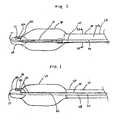
- FIG 1is a longitudinal cross sectional view of a distal end of a coaxial IAB catheter having a fiberoptic sensor in the tip.
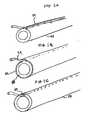
- FIG 1Ais a perspective view of distal end of inner tube 58, shown independent of catheter 10, with pressure sensing line 24 connected to an outer surface of inner tube 58.
- FIG 1Bis a perspective view of a distal end of inner tube 58, shown independent of catheter 10, with pressure sensing line sandwiched between an outer surface of inner tube 58 and an outer layer.
- FIG 1Cis a perspective view of a distal end of inner tube 58, shown independent of catheter 10, with pressure sensing line 24 embedded in the wall of inner tube 58.
- FIG 2is a longitudinal cross sectional view of a distal end of a co-lumen IAB catheter having a fiberoptic sensor in the tip.
- FIG 2Ais a transverse cross sectional view of the co-lumen IAB catheter in FIG 2 taken along lines 2A-2A.
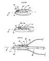
- FIG 3Ais a longitudinal cross sectional view of the tip having an embedded fiberoptic sensor in a first configuration.
- FIG 3Bis a longitudinal cross sectional view of the tip having an embedded fiberoptic sensor in a second configuration.
- FIG 3Cis a longitudinal cross sectional view of the tip having an embedded fiberoptic sensor in a third configuration.
- FIG 3Dis a longitudinal cross sectional view of the tip having an embedded fiberoptic sensor in a fourth configuration.
- FIG 1illustrates a longitudinal cross section of a distal portion of a dual lumen intra-aortic balloon (“IAB") catheter 10 comprising an outer tube 56, an inner tube 58, a tip 20, and a balloon membrane 30 connected on one end to the outer tube 56 and on the opposite end to the tip 20.
- Tip 20defines a tip lumen 21.
- Inner tube 58is disposed within the outer tube 56 and is connected to the tip 20 at its distal end.
- Inner tube 58defines an inner lumen 60 and outer tube 56 defines an outer lumen 28.
- Outer lumen 28is used for shuttling helium or another appropriate working gas or fluid for inflation and deflation of the balloon membrane 30.
- Outer tube 56may be coil or braid reinforced and made from polyurethane or polyimide.
- Inner tube 58may be made from polyimide or an alloy with shape memory and superelastic properties commonly referred to as Ni-Ti, NITINOLTM, and other industry names. Inner tube 58 may be connected to an inner surface of the outer tube 56 at one or more points to enhance pushability, stability, pumping speed, and pressure fidelity. Furthermore, inner tube 58 may be made from two or more tubes joined end-to-end, as disclosed in U.S. Patent No. 6,024,693 , or may have an inner tube having a variable diameter, as disclosed in. U.S. Patent Application No. 09/764831, filed on January 17, 2001 . Fiber optic sensor 22 is embedded in or attached to the tip 20 and preferably has a diameter less than or equal to (0.762 mm inches) 0.03.
- Pressure sensing line 24may be affixed to inner tube 58 and connects fiber optic sensor 22 to an optoelectronic interface (not shown) via an industry-standard "SC" connector (not shown).
- Pressure sensing line 24preferably is made of glass, but may be made of plastic or another material, and preferably has a diameter less than or equal to 0,152 mm (0.006 inches) Note that fiberoptic sensor 22 may be positioned in alternate locations along IAB catheter 10 as well as on a distal tip of an independent catheter that can be disposed within inner lumen 58.
- FIGS 1A-1Cillustrate perspective views of a distal end of inner tube 58 with pressure sensing line 24 connected to inner tube 58 in various configurations.
- pressure sensing line 24is connected to an outer surface of inner tube 58.
- pressure sensing line 24is disposed between inner tube 58 and a thin walled tube 64, which preferably is heat shrinkable. Heat shrinkable tubing with a wall thickness of less than or equal to (0.0254 mm inches) (0.001 mm) is available from Advanced Polymers, Inc., Salem, NH.
- pressure sensing line 24is embedded in the wall of inner tube 58. Note that although pressure sensing line 24 is shown running along a longitudinal axis of inner tube 58 it may also be wound helically.
- FIG 2illustrates a distal portion of another embodiment of the IAB catheter 10, comprising a balloon membrane 30, a tip 20, a co-lumen tube 56, an inner lumen extension tube 66, and a fiberoptic sensor 22.
- a co-lumen IABis disclosed in U.S. Patent No. 6,024,693 and U.S. Patent Application Serial No .09/412, 718, filed on October 5, 1999 .
- Tip 20is connected to a distal end of the balloon membrane 30 and to a distal end of the inner lumen extension tube 66. Tip 20 defines a tip lumen 21.
- a distal end of the co-lumen tube 56is connected to a proximal end of the balloon membrane 30 and to a proximal end of the inner lumen extension tube 66.
- the co-lumen tube 56may be coil or braid reinforced and made from polyurethane or polyimide.
- the preferred material for inner lumen extension tube 66is an alloy with shape memory and superelastic properties commonly referred to as Ni-Ti, NITINOLTM, and other industry names.
- Inner lumen extension tube 66may also be made from polyimide.
- the fiberoptic sensor 22is attached to tip 20 and pressure sensing line 24 which communicates signals generated by the fiberoptic sensor 22 to an optoelectronic interface (not shown).
- the pressure sensing line 24may be connected to the inner lumen extension tube 66 and co-lumen tube 56 in any of the ways pressure sensing line 24 is connected to the inner tube 58, illustrated in FIGS 1A-1C . Furthermore, the pressure sensing line may be embedded in the outer tube 56 as illustrated in FIG 2A .
- FIG 2Aillustrates a transverse cross section of outer tube 56, taken along line 2A-2A illustrated in FIG 2 , with pressure sensing line 24 embedded in the wall.
- Outer tube 56defines two distinct lumens, inner lumen 60 and outer lumen 28.
- Outer lumen 28is used for shuttling helium or another appropriate fluid or gas for inflation and deflation of balloon membrane 30.
- pressure sensing line 24may be embedded at a different location in outer tube 56, may be connected to a surface of outer tube 56, or may freely reside in outer lumen 28.
- the fiberoptic sensor 22may be positioned in alternate locations along IAB catheter 10 as well as on a distal tip of an independent catheter that can be disposed within the inner lumen 60.
- FIGS 3A-3Dillustrate alternate configurations for tip 20 incorporating a forward looking fiber optic sensor 22.
- longitudinal cross sections of tip 20are shown independent of the rest of catheter 10 for clarity.
- fiber optic sensoris embedded in tip 20 parallel to the longitudinal axis of tip 20 labeled A.
- Fiber optic sensor 22has an approximate outer diameter of 0.0635 mm (0.0025 inches) and has a pressure sensing surface or diaphragm 80 on a distal end which is exposed to protective pocket 82.
- Diaphragm 80may be made from silicone approximately 6 microns thick and is protected from physical damage and blood contact by protective pocket 82, which may contain a gel, fluid, gas, elastomer, or any other flexible protective material.
- Diaphragm 80may project into the pocket or may be flush with the protective pocket 82 wall.
- Membrane 84prevents leakage of gel or protective pocket 82.
- Pressure sensing line 24comprises a fiberoptic fiber having an outer diameter of approximately 0.152 mm (0.006 inches).
- FIG 3Band also FIGS 1 and 3
- the gel or protective pocket 82is shifted proximally.
- FIG 3Ca distal portion of balloon membrane 30 is used to seal protective pocket 82.
- protective pocket 82opens into inner lumen 60.
- Membrane 84prevents leakage of gel out of protective pocket 82.
- fiberoptic sensor 22is exposed to arterial pressure via tip lumen 21 and is less likely to be damaged upon insertion and placement of IAB catheter 10. Note that although forward looking fiber optic pressure sensors are illustrated, use of side looking sensors is anticipated as well.
- the fiberoptic sensor 22can be used to measure other important physiologic variables, such as, but not limited to temperature (as in the Luna Innovations sensor noted below), pCO2, pO2, pH, oxygen saturation, lactate, CPK, anesthetic agent concentration, various biological compounds, electrolytes, and nitric oxide. Blood pressure, as well as at least some of these variables, could be measured using either extrinsic or intrinsic fiberoptic sensors.
- Extrinsic sensorsuse the fiberoptic fiber to communicate information from a separate structure which is attached to the fiber.
- Intrinsic sensorssense information as a result of physical changes of the fiber itself. Intrinsic sensors have a particular advantage of being extremely small, rugged, and low in cost.
- the pressure sensing line 24terminates in an optoelectronic interface which provides a light source, light detector, optical components (such as a lens, splitter, and interferometer), power supply, and signal processing means.
- This optoelectronic interfaceis known in the art and can be connected to or integrated with another electronic device, such as a monitor or intra-aortic balloon pump.
- Light originating from the interfacetravels down the fiberoptic fiber, i.e. the pressure sensing line 24, by the well-known principal of total internal reflection to the sensing element.
- the sensing elementincorporates pressure responsive means which modifies the character of the light as a function of pressure. The modified light is in turn reflected back through the fiber to the interface.
- the optical components, light detector, and signal processing elements of the interfacework together to produce an electrical output that characterizes the pressure at the sensor. This output is translated into a displayed pressure waveform or digital pressure display by the IABP or monitor.
- Fiberoptic pressure monitoring sensors and optoelectronic interfaces suitable for this applicationare manufactured by several companies, including FISO Technologies Inc. (Quebec, Canada) and Luna Innovations (Blacksburg, VA).
- FISOutilizes a white light interferometric approach, as described in U.S. patents nos. 5,202,939 and 5,392,117 .
- Luna Innovationsuses a laser light source in an approach similar to that described in U.S. patent no. 5,301,001 .
- the fiberoptic sensoritself.
- One typewould employ a deformable diaphragm separated from the end of one or more fiberoptic fibers by a chamber.
- the chambermay be filled with air and vented to atmosphere to eliminate temperature-induced pressure changes within the chamber (these would be associated with signal drift).
- a disadvantage of this design in an IAB catheteris that an air-venting tube is required which occupies a portion of the cross-sectional area of the catheter. This tube reduces the potential to produce the catheter in a small size with acceptable performance.
- a more desirable approach to a fiberoptic pressure sensor for a small catheteris to utilize a design without a vent tube (as illustrated in FIGS 1, 2, and 3A-3D ).
- a sensorcan be produced by positioning the sensor diaphragm over a chamber with a vacuum (as currently practiced by FISO). With this approach, a sensor can be constructed which has little temperature-induced drift, assuming that the materials which are used to build the diaphragm and chamber have small coefficients of thermal expansion (ceramics, glass, and silicon are good choices).
- This approachmakes the device an absolute pressure sensor, which requires a separate barometric pressure sensor to convert absolute pressures to gauge pressures. In IABP applications, such a barometric pressure sensor could be built into the pump.
- Patent No. 5,158,529teaches another possible means for assuring the accuracy of gauge pressure values as indicated by a sensor in the IAB catheter; this approach compares the blood pressure values indicated by the catheter sensor with pressure values in the gas within a partially-filled catheter and pump, and adjusts the sensor-indicated pressure to agree with the gas pressure.
- Another approach to constructing a non-vented pressure sensoris to trap a gas in the chamber beneath the diaphragm and to monitor its temperature (as currently practiced by Luna Innovations). In this case, knowledge of the gas temperature within the chamber allows for correction of temperature-induced pressure changes. Ideally, if a gas is to occupy the chamber, it is dry and inert. It is possible that appropriate selection of the bias gas would improve linearization of the sensor or change its dynamic range.
Landscapes
- Health & Medical Sciences (AREA)
- Heart & Thoracic Surgery (AREA)
- Engineering & Computer Science (AREA)
- Life Sciences & Earth Sciences (AREA)
- Cardiology (AREA)
- Animal Behavior & Ethology (AREA)
- Veterinary Medicine (AREA)
- Public Health (AREA)
- Biomedical Technology (AREA)
- General Health & Medical Sciences (AREA)
- Anesthesiology (AREA)
- Hematology (AREA)
- Mechanical Engineering (AREA)
- Vascular Medicine (AREA)
- Biophysics (AREA)
- Medical Informatics (AREA)
- Surgery (AREA)
- Physics & Mathematics (AREA)
- Physiology (AREA)
- Pathology (AREA)
- Molecular Biology (AREA)
- Child & Adolescent Psychology (AREA)
- Transplantation (AREA)
- Pulmonology (AREA)
- Media Introduction/Drainage Providing Device (AREA)
- Measuring And Recording Apparatus For Diagnosis (AREA)
- Measuring Pulse, Heart Rate, Blood Pressure Or Blood Flow (AREA)
- Measurement Of The Respiration, Hearing Ability, Form, And Blood Characteristics Of Living Organisms (AREA)
Abstract
Description
- The invention relates to a catheter having enhanced pressure sensing capabilities. More particularly, the invention relates to single and dual lumen intra-aortic balloon catheters having a fiberoptic sensor connected to the catheter.
- A key function of many catheters is that of continuously monitoring blood pressure. In many cases, this monitoring must be performed with accurate measurement of high frequency components. For example, reliable detection of the dicrotic notch of the aortic blood pressure waveform typically requires a pressure signal having a bandwidth of 15Hz or better. Detection of the dicrotic notch is generally used for the inflation/deflation timing of an intra-aortic balloon ("IAB") catheter.
- Conventional invasive pressure monitoring is performed with low-cost fluid-filled transducers. A typical disposable monitoring kit, inclusive of all tubing, a continuous flush device, and a pre-calibrated transducer is very affordable. Unfortunately, these systems have several drawbacks. One major drawback is that bubbles or clots in the monitoring lines can reduce the frequency response of the system to a level below 15Hz, creating an "overdamped" condition. In other cases, the characteristics of the catheter and tubing can result in "ringing", which is associated with an underdamped condition. Furthermore, fluid-filled catheters can suffer from "catheter whip" (motion artifact), which is manifested as one or more high frequency deflections in the pressure signal. These problems can degrade the usefulness of the signal in applications such as intra-aortic balloon pumping (IABP). In particular, it is difficult, if not impossible, to automatically provide optimal timing of IABP using a pressure signal with a frequency response below 15Hz, or using signals with ringing or whip artifacts that mimic the physiologic dicrotic notch.
- Another disadvantage of the traditional fluid-filled transducer is that it requires the use of an inner guidewire tube. Traditionally, IAB catheters have two lumens in the catheter: a gas shuttle lumen and an inner guidewire lumen. The gas shuttle lumen has to be large enough to allow the gas to shuttle back and forth without undue restriction to ensure speedy inflation and deflation of the IAB membrane. In order to make the catheter smaller it is desirable to remove the inner guidewire lumen or tube, thus requiring an alternate means for measuring arterial pressure.
- Another means for monitoring blood pressure is to use a micromanometer, such as marketed by companies such as Millar, Endosonics, and Radi. See
U.S. Patents Nos. 5,431,628 and5,902,248 . These devices can have excellent frequency responses, with system bandwidths greater that 200Hz. They are not subject to the negative effects of bubbles and catheter whip, and retain good performance even in the presence of small blood clots. Unfortunately, they are very expensive, prone to signal drift, and can suffer from electrical interference. A common source of electrical interference in the setting of IABP therapy is the use of electrosurgery. In this situation, it is desirable to maintain a reliable pressure signal with which to trigger the balloon, as the ECG signal which normally triggers IABP operation becomes completely unreliable. Conventional fluid-filled transducer systems are relatively immune from this type of interference. Attempts have been made to use micromanometers for IABP timing, seeU.S. Patent Nos. 3,585,983 and4,733,652 . These attempts proved to be unreliable, as the device may be damaged during insertion and is also prone to signal drift. To address the drift issue,U.S. Patent no. 5,158,529 discloses a method for rezeroing the micromanometer by using the pressure from a partially filled balloon as it rests in the aorta. However, this method requires momentary interruption of IABP, which may be harmful to the critically ill patient. - While standard IAB catheters incorporating a fluid-filled transducer pressure measurement system or IAB catheters incorporating micromanometers may be suitable for the particular purpose employed, or for general use, they would not be as suitable for the purposes of the present invention as disclosed hereafter.
European Patent ApplicationEP 0307 162 discloses an apparatus for positioning a sensor probe in vivo, including a probe advancement mechanism and a mating interconnection for positioning a distal end of an indwelling catheter. The distal tip of the probe is advanced through the catheter to a predetermined position with respect to the distal tip of the catheter at which the sensor measurement is made.
European Patent ApplicationEP 0 234 046 discloses an intra-aortic balloon pump apparatus which comprises a catheter with a pressure transducer.
United States Published Patent5,427,114 discloses an apparatus for determining pressure at one or a number of intermediate points along a catheter inserted into a closed cavity. - Accordingly, there is a need for a reliable and affordable pressure monitoring approach that has high bandwidth pressure sensing, low signal drift, and freedom from electrosurgical interference. There is also a need to incorporate this technology into intra-aortic balloon catheters having small cross sectional profiles.
- The invention is an IAB catheter system, with either a double or single lumen, having enhanced blood pressure sensing capability. The IAB catheter has a fiberoptic sensor built into the tip of the IAB or connected to another part of the catheter.
The fiberoptic sensor is for sensing blood pressure and includes a diaphragm over a chamber with a vacuum. - Fiberoptic sensors have the advantage of being immune to electrical interference, and have the potential to be lower in cost than electronic micromanometers.
- To the accomplishment of the above and related objects the invention may be embodied in the form illustrated in the accompanying drawings. Attention is called to the fact, however, that the drawings are illustrative only. Variations are contemplated as being part of the invention, limited only by the scope of the claims.
- In the drawings, like elements are depicted by like reference numerals. The drawings are briefly described as follows.
FIG 1 is a longitudinal cross sectional view of a distal end of a coaxial IAB catheter having a fiberoptic sensor in the tip.FIG 1A is a perspective view of distal end ofinner tube 58, shown independent ofcatheter 10, withpressure sensing line 24 connected to an outer surface ofinner tube 58.FIG 1B is a perspective view of a distal end ofinner tube 58, shown independent ofcatheter 10, with pressure sensing line sandwiched between an outer surface ofinner tube 58 and an outer layer.FIG 1C is a perspective view of a distal end ofinner tube 58, shown independent ofcatheter 10, withpressure sensing line 24 embedded in the wall ofinner tube 58.FIG 2 is a longitudinal cross sectional view of a distal end of a co-lumen IAB catheter having a fiberoptic sensor in the tip.FIG 2A is a transverse cross sectional view of the co-lumen IAB catheter inFIG 2 taken along lines 2A-2A.FIG 3A is a longitudinal cross sectional view of the tip having an embedded fiberoptic sensor in a first configuration.FIG 3B is a longitudinal cross sectional view of the tip having an embedded fiberoptic sensor in a second configuration.FIG 3C is a longitudinal cross sectional view of the tip having an embedded fiberoptic sensor in a third configuration.FIG 3D is a longitudinal cross sectional view of the tip having an embedded fiberoptic sensor in a fourth configuration.FIG 1 illustrates a longitudinal cross section of a distal portion of a dual lumen intra-aortic balloon ("IAB")catheter 10 comprising anouter tube 56, aninner tube 58, atip 20, and aballoon membrane 30 connected on one end to theouter tube 56 and on the opposite end to thetip 20.Tip 20 defines atip lumen 21.Inner tube 58 is disposed within theouter tube 56 and is connected to thetip 20 at its distal end.Inner tube 58 defines aninner lumen 60 andouter tube 56 defines anouter lumen 28.Outer lumen 28 is used for shuttling helium or another appropriate working gas or fluid for inflation and deflation of theballoon membrane 30.Outer tube 56 may be coil or braid reinforced and made from polyurethane or polyimide.Inner tube 58 may be made from polyimide or an alloy with shape memory and superelastic properties commonly referred to as Ni-Ti, NITINOL™, and other industry names.Inner tube 58 may be connected to an inner surface of theouter tube 56 at one or more points to enhance pushability, stability, pumping speed, and pressure fidelity.
Furthermore,inner tube 58 may be made from two or more tubes joined end-to-end, as disclosed inU.S. Patent No. 6,024,693 , or may have an inner tube having a variable diameter, as disclosed in.U.S. Patent Application No. 09/764831, filed on January 17, 2001 Fiber optic sensor 22 is embedded in or attached to thetip 20 and preferably has a diameter less than or equal to (0.762 mm inches) 0.03. A forward looking end of thefiberoptic sensor 22 faces chamber 23.Pressure sensing line 24 may be affixed toinner tube 58 and connectsfiber optic sensor 22 to an optoelectronic interface (not shown) via an industry-standard "SC" connector (not shown).Pressure sensing line 24 preferably is made of glass, but may be made of plastic or another material, and preferably has a diameter less than or equal to 0,152 mm (0.006 inches) Note thatfiberoptic sensor 22 may be positioned in alternate locations alongIAB catheter 10 as well as on a distal tip of an independent catheter that can be disposed withininner lumen 58.FIGS 1A-1C illustrate perspective views of a distal end ofinner tube 58 withpressure sensing line 24 connected toinner tube 58 in various configurations. InFIG 1A ,pressure sensing line 24, is connected to an outer surface ofinner tube 58. InFIG 1B ,pressure sensing line 24 is disposed betweeninner tube 58 and a thin walled tube 64, which preferably is heat shrinkable. Heat shrinkable tubing witha wall thickness of less than or equal to (0.0254 mm inches) (0.001 mm) is available from Advanced Polymers, Inc., Salem, NH. InFIG 1C ,pressure sensing line 24 is embedded in the wall ofinner tube 58. Note that althoughpressure sensing line 24 is shown running along a longitudinal axis ofinner tube 58 it may also be wound helically.FIG 2 illustrates a distal portion of another embodiment of theIAB catheter 10, comprising aballoon membrane 30, atip 20, aco-lumen tube 56, an innerlumen extension tube 66, and afiberoptic sensor 22. Detailed structure of a co-lumen IAB is disclosed inU.S. Patent No. 6,024,693 andU.S. Patent Application Serial No .09/412, 718, filed on October 5, 1999 Tip 20 is connected to a distal end of theballoon membrane 30 and to a distal end of the innerlumen extension tube 66.Tip 20 defines atip lumen 21. A distal end of theco-lumen tube 56 is connected to a proximal end of theballoon membrane 30 and to a proximal end of the innerlumen extension tube 66. Theco-lumen tube 56 may be coil or braid reinforced and made from polyurethane or polyimide. The preferred material for innerlumen extension tube 66 is an alloy with shape memory and superelastic properties commonly referred to as Ni-Ti, NITINOL™, and other industry names. Innerlumen extension tube 66 may also be made from polyimide. Thefiberoptic sensor 22 is attached to tip 20 andpressure sensing line 24 which communicates signals generated by thefiberoptic sensor 22 to an optoelectronic interface (not shown). Thepressure sensing line 24 may be connected to the innerlumen extension tube 66 andco-lumen tube 56 in any of the wayspressure sensing line 24 is connected to theinner tube 58, illustrated inFIGS 1A-1C . Furthermore, the pressure sensing line may be embedded in theouter tube 56 as illustrated inFIG 2A .FIG 2A illustrates a transverse cross section ofouter tube 56, taken along line 2A-2A illustrated inFIG 2 , withpressure sensing line 24 embedded in the wall.Outer tube 56 defines two distinct lumens,inner lumen 60 andouter lumen 28.Outer lumen 28 is used for shuttling helium or another appropriate fluid or gas for inflation and deflation ofballoon membrane 30. Note thatpressure sensing line 24 may be embedded at a different location inouter tube 56, may be connected to a surface ofouter tube 56, or may freely reside inouter lumen 28. Note also that thefiberoptic sensor 22 may be positioned in alternate locations alongIAB catheter 10 as well as on a distal tip of an independent catheter that can be disposed within theinner lumen 60.FIGS 3A-3D illustrate alternate configurations fortip 20 incorporating a forward lookingfiber optic sensor 22. InFIG 3A and FIG 3B longitudinal cross sections oftip 20 are shown independent of the rest ofcatheter 10 for clarity. InFIG 3A fiber optic sensor is embedded intip 20 parallel to the longitudinal axis oftip 20 labeled A.Fiber optic sensor 22 has an approximate outer diameter of 0.0635 mm (0.0025 inches) and has a pressure sensing surface ordiaphragm 80 on a distal end which is exposed toprotective pocket 82.Diaphragm 80 may be made from silicone approximately 6 microns thick and is protected from physical damage and blood contact byprotective pocket 82, which may contain a gel, fluid, gas, elastomer, or any other flexible protective material.Diaphragm 80 may project into the pocket or may be flush with theprotective pocket 82 wall.Membrane 84 prevents leakage of gel orprotective pocket 82.Pressure sensing line 24 comprises a fiberoptic fiber having an outer diameter of approximately 0.152 mm (0.006 inches). InFIG 3B (and alsoFIGS 1 and3 ) the gel orprotective pocket 82 is shifted proximally. InFIG 3C a distal portion ofballoon membrane 30 is used to sealprotective pocket 82. InFIG 3D protective pocket 82 opens intoinner lumen 60.Membrane 84 prevents leakage of gel out ofprotective pocket 82. In thislocation fiberoptic sensor 22 is exposed to arterial pressure viatip lumen 21 and is less likely to be damaged upon insertion and placement ofIAB catheter 10. Note that although forward looking fiber optic pressure sensors are illustrated, use of side looking sensors is anticipated as well.- In addition to sensing blood pressure, the
fiberoptic sensor 22 can be used to measure other important physiologic variables, such as, but not limited to temperature (as in the Luna Innovations sensor noted below), pCO2, pO2, pH, oxygen saturation, lactate, CPK, anesthetic agent concentration, various biological compounds, electrolytes, and nitric oxide. Blood pressure, as well as at least some of these variables, could be measured using either extrinsic or intrinsic fiberoptic sensors. Extrinsic sensors use the fiberoptic fiber to communicate information from a separate structure which is attached to the fiber. Intrinsic sensors sense information as a result of physical changes of the fiber itself. Intrinsic sensors have a particular advantage of being extremely small, rugged, and low in cost. - As indicated above the
pressure sensing line 24 terminates in an optoelectronic interface which provides a light source, light detector, optical components (such as a lens, splitter, and interferometer), power supply, and signal processing means. This optoelectronic interface is known in the art and can be connected to or integrated with another electronic device, such as a monitor or intra-aortic balloon pump. Light originating from the interface travels down the fiberoptic fiber, i.e. thepressure sensing line 24, by the well-known principal of total internal reflection to the sensing element. The sensing element incorporates pressure responsive means which modifies the character of the light as a function of pressure. The modified light is in turn reflected back through the fiber to the interface. The optical components, light detector, and signal processing elements of the interface work together to produce an electrical output that characterizes the pressure at the sensor. This output is translated into a displayed pressure waveform or digital pressure display by the IABP or monitor. - Fiberoptic pressure monitoring sensors and optoelectronic interfaces suitable for this application are manufactured by several companies, including FISO Technologies Inc. (Quebec, Canada) and Luna Innovations (Blacksburg, VA). FISO utilizes a white light interferometric approach, as described in
U.S. patents nos. 5,202,939 and5,392,117 .
Luna Innovations uses a laser light source in an approach similar to that described inU.S. patent no. 5,301,001 . - There are a variety of possible configurations for the fiberoptic sensor itself. One type would employ a deformable diaphragm separated from the end of one or more fiberoptic fibers by a chamber. The chamber may be filled with air and vented to atmosphere to eliminate temperature-induced pressure changes within the chamber (these would be associated with signal drift). A disadvantage of this design in an IAB catheter is that an air-venting tube is required which occupies a portion of the cross-sectional area of the catheter. This tube reduces the potential to produce the catheter in a small size with acceptable performance.
- A more desirable approach to a fiberoptic pressure sensor for a small catheter is to utilize a design without a vent tube (as illustrated in
FIGS 1, 2, and 3A-3D ). Such a sensor can be produced by positioning the sensor diaphragm over a chamber with a vacuum (as currently practiced by FISO). With this approach, a sensor can be constructed which has little temperature-induced drift, assuming that the materials which are used to build the diaphragm and chamber have small coefficients of thermal expansion (ceramics, glass, and silicon are good choices). This approach makes the device an absolute pressure sensor, which requires a separate barometric pressure sensor to convert absolute pressures to gauge pressures. In IABP applications, such a barometric pressure sensor could be built into the pump.U.S. Patent No. 5,158,529 teaches another possible means for assuring the accuracy of gauge pressure values as indicated by a sensor in the IAB catheter; this approach compares the blood pressure values indicated by the catheter sensor with pressure values in the gas within a partially-filled catheter and pump, and adjusts the sensor-indicated pressure to agree with the gas pressure. - Another approach to constructing a non-vented pressure sensor is to trap a gas in the chamber beneath the diaphragm and to monitor its temperature (as currently practiced by Luna Innovations). In this case, knowledge of the gas temperature within the chamber allows for correction of temperature-induced pressure changes. Ideally, if a gas is to occupy the chamber, it is dry and inert. It is possible that appropriate selection of the bias gas would improve linearization of the sensor or change its dynamic range.
Claims (2)
- A balloon catheter system comprising a fiberoptic sensor catheter and a balloon catheter (10), said balloon catheter comprising a balloon membrane (30), a tip (20) having a tip lumen (21), an outer tube (56), and an inner tube (58) disposed within an outer surface of said outer tube, said inner tube extending beyond a distal end of the outer tube (56), a distal end of the balloon membrane (30) being connected to the tip (20) and to a distal end of the inner tube (58), said fiberoptic sensor catheter comprising a tube having a fiberoptic sensor (22) connected to a distal end, said fiberoptic sensor (22) being connected to a distal end of a fiberoptic fiber (24) which is connected to the tube, said fiberoptic sensor catheter fitting within the inner tube (58) and in the tip lumen (21), wherein said fiberoptic sensor (22) is for sensing blood pressure and includes a diaphragm over a chamber with a vacuum.
- The balloon catheter system as claimed in claim 1 wherein the inner tube (58) is connected to the outer tube (56).
Priority Applications (1)
| Application Number | Priority Date | Filing Date | Title |
|---|---|---|---|
| EP10009992AEP2275162A3 (en) | 2000-12-12 | 2001-12-10 | Intra-aortic balloon catheter having a fiberoptic sensor |
Applications Claiming Priority (4)
| Application Number | Priority Date | Filing Date | Title |
|---|---|---|---|
| US09/734,755US20020072679A1 (en) | 2000-12-12 | 2000-12-12 | Intra-aortic balloon catheter having a fiberoptic sensor |
| US09/925,143US20020072680A1 (en) | 2000-12-12 | 2001-08-09 | Intra-aortic balloon catheter having a fiberoptic sensor |
| EP04003691AEP1419796B1 (en) | 2000-12-12 | 2001-12-10 | Intra-aortic balloon catheter having a fiberoptic sensor |
| EP01270357AEP1409057B1 (en) | 2000-12-12 | 2001-12-10 | Intra-Aortic balloon catheter having a fiberoptic sensor |
Related Parent Applications (3)
| Application Number | Title | Priority Date | Filing Date |
|---|---|---|---|
| EP04003691ADivisionEP1419796B1 (en) | 2000-12-12 | 2001-12-10 | Intra-aortic balloon catheter having a fiberoptic sensor |
| EP01270357.5Division | 2001-12-10 | ||
| EP04003691.5Division | 2004-02-19 |
Related Child Applications (1)
| Application Number | Title | Priority Date | Filing Date |
|---|---|---|---|
| EP10009992.8Division-Into | 2010-09-20 |
Publications (3)
| Publication Number | Publication Date |
|---|---|
| EP1764124A2 EP1764124A2 (en) | 2007-03-21 |
| EP1764124A3 EP1764124A3 (en) | 2007-05-30 |
| EP1764124B1true EP1764124B1 (en) | 2011-01-19 |
Family
ID=27112778
Family Applications (4)
| Application Number | Title | Priority Date | Filing Date |
|---|---|---|---|
| EP06024468AExpired - LifetimeEP1764124B1 (en) | 2000-12-12 | 2001-12-10 | Intra-aortic balloon catheter having a fiberoptic sensor |
| EP01270357AExpired - LifetimeEP1409057B1 (en) | 2000-12-12 | 2001-12-10 | Intra-Aortic balloon catheter having a fiberoptic sensor |
| EP04003691AExpired - LifetimeEP1419796B1 (en) | 2000-12-12 | 2001-12-10 | Intra-aortic balloon catheter having a fiberoptic sensor |
| EP08001306AExpired - LifetimeEP1911484B1 (en) | 2000-12-12 | 2001-12-10 | Intra-aortic balloon catheter having a fiberoptic sensor |
Family Applications After (3)
| Application Number | Title | Priority Date | Filing Date |
|---|---|---|---|
| EP01270357AExpired - LifetimeEP1409057B1 (en) | 2000-12-12 | 2001-12-10 | Intra-Aortic balloon catheter having a fiberoptic sensor |
| EP04003691AExpired - LifetimeEP1419796B1 (en) | 2000-12-12 | 2001-12-10 | Intra-aortic balloon catheter having a fiberoptic sensor |
| EP08001306AExpired - LifetimeEP1911484B1 (en) | 2000-12-12 | 2001-12-10 | Intra-aortic balloon catheter having a fiberoptic sensor |
Country Status (4)
| Country | Link |
|---|---|
| EP (4) | EP1764124B1 (en) |
| AT (1) | ATE387927T1 (en) |
| AU (1) | AU2002220271A1 (en) |
| WO (1) | WO2002047751A2 (en) |
Cited By (1)
| Publication number | Priority date | Publication date | Assignee | Title |
|---|---|---|---|---|
| EP4338786A1 (en) | 2022-09-13 | 2024-03-20 | NuPulseCV, Inc. | Intra-aortic balloon pump assembly with pressure sensor |
Families Citing this family (61)
| Publication number | Priority date | Publication date | Assignee | Title |
|---|---|---|---|---|
| US6999807B2 (en) | 2003-01-23 | 2006-02-14 | Scimed Life Systems, Inc. | pH measuring balloon |
| US8075498B2 (en) | 2005-03-04 | 2011-12-13 | Endosense Sa | Medical apparatus system having optical fiber load sensing capability |
| EP2363073B1 (en) | 2005-08-01 | 2015-10-07 | St. Jude Medical Luxembourg Holding S.à.r.l. | Medical apparatus system having optical fiber load sensing capability |
| US8989528B2 (en) | 2006-02-22 | 2015-03-24 | Hansen Medical, Inc. | Optical fiber grating sensors and methods of manufacture |
| US8567265B2 (en) | 2006-06-09 | 2013-10-29 | Endosense, SA | Triaxial fiber optic force sensing catheter |
| US8157789B2 (en) | 2007-05-24 | 2012-04-17 | Endosense Sa | Touch sensing catheter |
| US8622935B1 (en) | 2007-05-25 | 2014-01-07 | Endosense Sa | Elongated surgical manipulator with body position and distal force sensing |
| EP2626030A3 (en) | 2007-08-14 | 2017-03-08 | Koninklijke Philips N.V. | Robotic instrument systems and methods utilizing optical fiber sensors |
| RU2478338C2 (en) | 2008-09-11 | 2013-04-10 | Эсист Медикал Системз, Инк. | Device and method of physiological sensor delivery |
| JP5347656B2 (en)* | 2009-03-31 | 2013-11-20 | 日本ゼオン株式会社 | catheter |
| DE102009047845A1 (en)* | 2009-09-30 | 2011-03-31 | Abiomed Europe Gmbh | Ventricular Assist Device |
| US8771289B2 (en) | 2009-12-21 | 2014-07-08 | Acist Medical Systems, Inc. | Thrombus removal device and system |
| EP2560722A2 (en) | 2010-04-21 | 2013-02-27 | The Regents of the University of Michigan | Fluoroscopy-independent, endovascular aortic occlusion system |
| US20120071752A1 (en) | 2010-09-17 | 2012-03-22 | Sewell Christopher M | User interface and method for operating a robotic medical system |
| US20120191079A1 (en) | 2011-01-20 | 2012-07-26 | Hansen Medical, Inc. | System and method for endoluminal and translumenal therapy |
| CN103607961B (en) | 2011-04-14 | 2016-12-14 | 圣犹达医疗用品卢森堡控股有限公司 | Compact force sensor for conduit |
| JP6059207B2 (en) | 2011-05-11 | 2017-01-11 | アシスト・メディカル・システムズ,インコーポレイテッド | Intravascular detection method and detection system |
| US20130030363A1 (en) | 2011-07-29 | 2013-01-31 | Hansen Medical, Inc. | Systems and methods utilizing shape sensing fibers |
| DE102012207053A1 (en) | 2012-04-27 | 2013-10-31 | Abiomed Europe Gmbh | INTRAVASAL ROTATION BLOOD PUMP |
| DE102012207049A1 (en)* | 2012-04-27 | 2015-08-13 | Abiomed Europe Gmbh | INTRAVASAL ROTATION BLOOD PUMP |
| US9241641B2 (en) | 2012-07-20 | 2016-01-26 | Acist Medical Systems, Inc. | Fiber optic sensor assembly for sensor delivery device |
| US10569062B2 (en) | 2013-09-09 | 2020-02-25 | Prytime Medical Devices, Inc. | Low profile occlusion catheter |
| US10130269B2 (en) | 2013-11-14 | 2018-11-20 | Medtronic Vascular, Inc | Dual lumen catheter for providing a vascular pressure measurement |
| US9877660B2 (en) | 2013-11-14 | 2018-01-30 | Medtronic Vascular Galway | Systems and methods for determining fractional flow reserve without adenosine or other pharmalogical agent |
| US9913585B2 (en) | 2014-01-15 | 2018-03-13 | Medtronic Vascular, Inc. | Catheter for providing vascular pressure measurements |
| US10232142B2 (en) | 2014-06-10 | 2019-03-19 | Prytime Medical Devices, Inc. | Conduit guiding tip |
| US10244951B2 (en) | 2014-06-10 | 2019-04-02 | Acist Medical Systems, Inc. | Physiological sensor delivery device and method |
| US10201284B2 (en) | 2014-06-16 | 2019-02-12 | Medtronic Vascular Inc. | Pressure measuring catheter having reduced error from bending stresses |
| US11330989B2 (en) | 2014-06-16 | 2022-05-17 | Medtronic Vascular, Inc. | Microcatheter sensor design for mounting sensor to minimize induced strain |
| US10973418B2 (en) | 2014-06-16 | 2021-04-13 | Medtronic Vascular, Inc. | Microcatheter sensor design for minimizing profile and impact of wire strain on sensor |
| JP6184929B2 (en)* | 2014-10-10 | 2017-08-23 | 国立大学法人東北大学 | Manufacturing method of catheter with sensor |
| US10194812B2 (en) | 2014-12-12 | 2019-02-05 | Medtronic Vascular, Inc. | System and method of integrating a fractional flow reserve device with a conventional hemodynamic monitoring system |
| CA2980018C (en) | 2015-03-19 | 2018-02-20 | Prytime Medical Devices, Inc. | System and method for low-profile occlusion balloon catheter |
| EP3088018A1 (en)* | 2015-04-30 | 2016-11-02 | ECP Entwicklungsgesellschaft mbH | Rotor for a fluid pump and method and mould for its preparation |
| US11445937B2 (en) | 2016-01-07 | 2022-09-20 | St. Jude Medical International Holding S.À R.L. | Medical device with multi-core fiber for optical sensing |
| US10368872B2 (en)* | 2016-06-02 | 2019-08-06 | Prytime Medical Devices, Inc. | System and method for low profile occlusion balloon catheter |
| US10342906B2 (en) | 2016-06-06 | 2019-07-09 | Abiomed, Inc. | Blood pump assembly having a sensor and a sensor shield |
| US11272850B2 (en) | 2016-08-09 | 2022-03-15 | Medtronic Vascular, Inc. | Catheter and method for calculating fractional flow reserve |
| EP4327732A3 (en) | 2017-01-12 | 2024-04-24 | The Regents of The University of California | Endovascular perfusion augmentation for critical care |
| US11330994B2 (en) | 2017-03-08 | 2022-05-17 | Medtronic Vascular, Inc. | Reduced profile FFR catheter |
| CA3060519A1 (en) | 2017-04-21 | 2018-10-25 | The Regents Of The University Of California | Aortic flow meter and pump for partial-aortic occlusion |
| US10646122B2 (en) | 2017-04-28 | 2020-05-12 | Medtronic Vascular, Inc. | FFR catheter with covered distal pressure sensor and method of manufacture |
| JP2017209501A (en)* | 2017-05-26 | 2017-11-30 | 国立大学法人東北大学 | Catheter with sensor |
| US11235124B2 (en) | 2017-08-09 | 2022-02-01 | Medtronic Vascular, Inc. | Collapsible catheter and method for calculating fractional flow reserve |
| US11219741B2 (en) | 2017-08-09 | 2022-01-11 | Medtronic Vascular, Inc. | Collapsible catheter and method for calculating fractional flow reserve |
| CN112004563B (en) | 2018-02-01 | 2024-08-06 | 施菲姆德控股有限责任公司 | Intravascular blood pump and methods of use and manufacture |
| ES2915828T3 (en) | 2018-04-20 | 2022-06-27 | Acist Medical Sys Inc | Evaluation of a glass |
| US12161857B2 (en) | 2018-07-31 | 2024-12-10 | Shifamed Holdings, Llc | Intravascular blood pumps and methods of use |
| EP3833273A4 (en) | 2018-08-06 | 2022-06-29 | Prytime Medical Devices, Inc. | System and method for low profile occlusion balloon catheter |
| US11185244B2 (en) | 2018-08-13 | 2021-11-30 | Medtronic Vascular, Inc. | FFR catheter with suspended pressure sensor |
| WO2020073047A1 (en) | 2018-10-05 | 2020-04-09 | Shifamed Holdings, Llc | Intravascular blood pumps and methods of use |
| JP7404360B2 (en) | 2018-10-31 | 2023-12-25 | アシスト・メディカル・システムズ,インコーポレイテッド | fluid pressure sensor protection |
| WO2021011473A1 (en) | 2019-07-12 | 2021-01-21 | Shifamed Holdings, Llc | Intravascular blood pumps and methods of manufacture and use |
| US12121713B2 (en) | 2019-09-25 | 2024-10-22 | Shifamed Holdings, Llc | Catheter blood pumps and collapsible blood conduits |
| EP4501393A3 (en) | 2019-09-25 | 2025-04-09 | Shifamed Holdings, LLC | Catheter blood pumps and collapsible pump housings |
| EP4072650A4 (en) | 2019-12-11 | 2024-01-10 | Shifamed Holdings, LLC | Descending aorta and vena cava blood pumps |
| US11975158B2 (en)* | 2020-01-10 | 2024-05-07 | Boston Scientific Scimed, Inc. | Medical device with haptic sensing capabilities |
| EP4121159A2 (en) | 2020-03-16 | 2023-01-25 | Certus Critical Care, Inc. | Blood flow control devices, systems, and methods and error detection thereof |
| JP7505546B2 (en)* | 2020-03-30 | 2024-06-25 | 日本ゼオン株式会社 | Sensor-equipped catheter |
| WO2022197895A1 (en) | 2021-03-18 | 2022-09-22 | Prytime Medical Devices, Inc. | Vascular occlusion catheter |
| CN120615019A (en)* | 2023-03-14 | 2025-09-09 | 脉凯斯私人有限公司 | Catheter components |
Family Cites Families (34)
| Publication number | Priority date | Publication date | Assignee | Title |
|---|---|---|---|---|
| US3585983A (en) | 1968-03-05 | 1971-06-22 | Adrian Kantrowitz | Cardiac assisting pump |
| US4201222A (en)* | 1977-08-31 | 1980-05-06 | Thomas Haase | Method and apparatus for in vivo measurement of blood gas partial pressures, blood pressure and blood pulse |
| US4934996A (en)* | 1984-02-27 | 1990-06-19 | Boston Scientific Corporation | Pressure-controlled intermittent coronary sinus occlusion apparatus and method |
| SE441725B (en)* | 1985-01-10 | 1985-11-04 | Bertil Hok | SYSTEMS FOR PHYSIOLOGICAL PRESSURE RECORDS |
| JPH0628632B2 (en)* | 1985-12-31 | 1994-04-20 | アイシン精機株式会社 | Aortic balloon pump device |
| US4733652A (en) | 1985-12-31 | 1988-03-29 | Aisin Seiki Kabushiki Kaisha | Intra-aortic balloon |
| US4795434A (en)* | 1987-09-10 | 1989-01-03 | C. R. Bard, Inc. | Apparatus for positioning a sensor in vivo |
| US4924877A (en)* | 1988-11-25 | 1990-05-15 | Ambrook Medical Concepts, Inc. | Pressure sensing catheter |
| US5042985A (en)* | 1989-05-11 | 1991-08-27 | Advanced Cardiovascular Systems, Inc. | Dilatation catheter suitable for peripheral arteries |
| US5313957A (en)* | 1990-01-05 | 1994-05-24 | Medamicus, Inc. | Guide wire mounted pressure transducer |
| JP2902040B2 (en) | 1990-03-29 | 1999-06-07 | アイシン精機株式会社 | Drive device of balloon pump with arterial pressure sensor |
| US5766151A (en)* | 1991-07-16 | 1998-06-16 | Heartport, Inc. | Endovascular system for arresting the heart |
| US5795325A (en)* | 1991-07-16 | 1998-08-18 | Heartport, Inc. | Methods and apparatus for anchoring an occluding member |
| US5209727A (en)* | 1992-01-29 | 1993-05-11 | Interventional Technologies, Inc. | Guide wire with integral angioplasty balloon |
| US5335658A (en)* | 1992-06-29 | 1994-08-09 | Minnesota Mining And Manufacturing Company | Intravascular blood parameter sensing system |
| CA2074289C (en) | 1992-07-21 | 1999-09-14 | Claude Belleville | Fabry-perot optical sensing device for measuring a physical parameter |
| US5431628A (en) | 1992-09-29 | 1995-07-11 | Millar Instruments, Inc. | Pressure-sensing diagnostic catheter |
| CA2113684A1 (en) | 1993-01-19 | 1994-07-20 | Robert L. Wilcox | Single-lumen over-the-wire iab catheter |
| US5427114A (en)* | 1993-08-19 | 1995-06-27 | Fiberoptic Sensor Technologies, Inc. | Dual pressure sensing catheter |
| US5429597A (en)* | 1994-03-01 | 1995-07-04 | Boston Scientific Corporation | Kink resistant balloon catheter and method for use |
| US5505699A (en)* | 1994-03-24 | 1996-04-09 | Schneider (Usa) Inc. | Angioplasty device |
| EP0674912A1 (en)* | 1994-03-31 | 1995-10-04 | Leocor, Inc. | Coaxial/Double lumen catheter |
| US5779688A (en)* | 1994-10-28 | 1998-07-14 | Intella Interventional Systems, Inc. | Low profile balloon-on-a-wire catheter with shapeable and/or deflectable tip and method |
| US5716373A (en)* | 1995-07-19 | 1998-02-10 | Datascope Investment Corp. | Support member for reduced diameter balloon catheter, and intra-aortic balloon catheter using the same |
| US5701905A (en)* | 1995-11-13 | 1997-12-30 | Localmed, Inc. | Guide catheter with sensing element |
| US5906606A (en)* | 1995-12-04 | 1999-05-25 | Target Therapuetics, Inc. | Braided body balloon catheter |
| IL127138A0 (en)* | 1996-05-20 | 1999-09-22 | Percusurge Inc | Catheter balloon core wire |
| US5902248A (en) | 1996-11-06 | 1999-05-11 | Millar Instruments, Inc. | Reduced size catheter tip measurement device |
| US5928155A (en)* | 1997-01-24 | 1999-07-27 | Cardiox Corporation | Cardiac output measurement with metabolizable analyte containing fluid |
| WO1999013934A1 (en)* | 1997-09-12 | 1999-03-25 | Nippon Zeon Co., Ltd. | Balloon catheter |
| DE69828429T2 (en)* | 1997-10-08 | 2005-12-08 | Kaneka Corp. | BALLOON CATHETER AND MANUFACTURING METHOD THEREFOR |
| US5916153A (en)* | 1997-10-27 | 1999-06-29 | Rhea, Jr.; W. Gardner | Multifunction catheter |
| US6024693A (en) | 1998-10-16 | 2000-02-15 | Datascope Investment Corp. | Intra-aortic balloon catheter |
| JP4191849B2 (en)* | 1999-05-28 | 2008-12-03 | 泉工医科工業株式会社 | Balloon catheter |
- 2001
- 2001-12-10EPEP06024468Apatent/EP1764124B1/ennot_activeExpired - Lifetime
- 2001-12-10EPEP01270357Apatent/EP1409057B1/ennot_activeExpired - Lifetime
- 2001-12-10EPEP04003691Apatent/EP1419796B1/ennot_activeExpired - Lifetime
- 2001-12-10EPEP08001306Apatent/EP1911484B1/ennot_activeExpired - Lifetime
- 2001-12-10WOPCT/US2001/047707patent/WO2002047751A2/ennot_activeApplication Discontinuation
- 2001-12-10ATAT04003691Tpatent/ATE387927T1/ennot_activeIP Right Cessation
- 2001-12-10AUAU2002220271Apatent/AU2002220271A1/ennot_activeAbandoned
Cited By (1)
| Publication number | Priority date | Publication date | Assignee | Title |
|---|---|---|---|---|
| EP4338786A1 (en) | 2022-09-13 | 2024-03-20 | NuPulseCV, Inc. | Intra-aortic balloon pump assembly with pressure sensor |
Also Published As
| Publication number | Publication date |
|---|---|
| ATE387927T1 (en) | 2008-03-15 |
| EP1911484A2 (en) | 2008-04-16 |
| EP1764124A2 (en) | 2007-03-21 |
| EP1419796B1 (en) | 2008-03-05 |
| EP1911484B1 (en) | 2010-09-22 |
| EP1409057B1 (en) | 2008-09-24 |
| WO2002047751A2 (en) | 2002-06-20 |
| EP1419796A3 (en) | 2005-05-04 |
| EP1409057A2 (en) | 2004-04-21 |
| AU2002220271A1 (en) | 2002-06-24 |
| WO2002047751A3 (en) | 2003-05-01 |
| EP1419796A2 (en) | 2004-05-19 |
| EP1764124A3 (en) | 2007-05-30 |
| EP1911484A3 (en) | 2008-06-18 |
Similar Documents
| Publication | Publication Date | Title |
|---|---|---|
| EP1764124B1 (en) | Intra-aortic balloon catheter having a fiberoptic sensor | |
| US20020072679A1 (en) | Intra-aortic balloon catheter having a fiberoptic sensor | |
| US6935999B2 (en) | Intra-aortic balloon catheter having a dual sensor pressure sensing system | |
| US4991590A (en) | Fiber optic intravascular blood pressure transducer | |
| US4951669A (en) | Blood parameter measurement system | |
| US5701905A (en) | Guide catheter with sensing element | |
| EP3508116B1 (en) | Fiber optic sensor assembly for sensor delivery device | |
| EP0479341B1 (en) | Intravascular blood parameter measurement system | |
| US6398738B1 (en) | Method and apparatus for reconstructing a high fidelity pressure waveform with a balloon catheter | |
| US4711249A (en) | Circumferential membrane, fluid coupled catheter | |
| US20130116579A1 (en) | Medical system, and a method in relation to the medical system | |
| CN110049729B (en) | Guidewire system for measuring intravascular pressure | |
| JP2000333913A (en) | Balloon catheter | |
| WO2012092441A2 (en) | Lumen based pressure sensing guidewire system with distortion correction | |
| HK1129609A (en) | Intra-aortic balloon catheter having a fiberoptic sensor | |
| HK1067320B (en) | Intra-aortic balloon catheter having a fiberoptic sensor | |
| WO2018047796A1 (en) | Pressure measuring catheter | |
| JP2006515219A (en) | pH measurement balloon | |
| JP2000300524A (en) | Balloon catheter | |
| HK40011379B (en) | Fiber optic sensor assembly for sensor delivery device | |
| HK1067288B (en) | Intra-aortic balloon catheter having a dual sensor pressure sensing system |
Legal Events
| Date | Code | Title | Description |
|---|---|---|---|
| PUAI | Public reference made under article 153(3) epc to a published international application that has entered the european phase | Free format text:ORIGINAL CODE: 0009012 | |
| 17P | Request for examination filed | Effective date:20061124 | |
| AC | Divisional application: reference to earlier application | Ref document number:1419796 Country of ref document:EP Kind code of ref document:P Ref document number:1409057 Country of ref document:EP Kind code of ref document:P | |
| AK | Designated contracting states | Kind code of ref document:A2 Designated state(s):AT BE CH CY DE DK ES FI FR GB GR IE IT LI LU MC NL PT SE TR | |
| PUAL | Search report despatched | Free format text:ORIGINAL CODE: 0009013 | |
| AK | Designated contracting states | Kind code of ref document:A3 Designated state(s):AT BE CH CY DE DK ES FI FR GB GR IE IT LI LU MC NL PT SE TR | |
| 17Q | First examination report despatched | Effective date:20071114 | |
| AKX | Designation fees paid | Designated state(s):AT BE CH CY DE DK ES FI FR GB GR IE IT LI LU MC NL PT SE TR | |
| GRAP | Despatch of communication of intention to grant a patent | Free format text:ORIGINAL CODE: EPIDOSNIGR1 | |
| GRAS | Grant fee paid | Free format text:ORIGINAL CODE: EPIDOSNIGR3 | |
| GRAA | (expected) grant | Free format text:ORIGINAL CODE: 0009210 | |
| AC | Divisional application: reference to earlier application | Ref document number:1409057 Country of ref document:EP Kind code of ref document:P Ref document number:1419796 Country of ref document:EP Kind code of ref document:P | |
| AK | Designated contracting states | Kind code of ref document:B1 Designated state(s):AT BE CH CY DE DK ES FI FR GB GR IE IT LI LU MC NL PT SE TR | |
| REG | Reference to a national code | Ref country code:GB Ref legal event code:FG4D | |
| REG | Reference to a national code | Ref country code:CH Ref legal event code:EP | |
| REG | Reference to a national code | Ref country code:IE Ref legal event code:FG4D | |
| REF | Corresponds to: | Ref document number:60143916 Country of ref document:DE Date of ref document:20110303 Kind code of ref document:P | |
| REG | Reference to a national code | Ref country code:DE Ref legal event code:R096 Ref document number:60143916 Country of ref document:DE Effective date:20110303 | |
| REG | Reference to a national code | Ref country code:NL Ref legal event code:VDEP Effective date:20110119 | |
| PG25 | Lapsed in a contracting state [announced via postgrant information from national office to epo] | Ref country code:PT Free format text:LAPSE BECAUSE OF FAILURE TO SUBMIT A TRANSLATION OF THE DESCRIPTION OR TO PAY THE FEE WITHIN THE PRESCRIBED TIME-LIMIT Effective date:20110519 Ref country code:SE Free format text:LAPSE BECAUSE OF FAILURE TO SUBMIT A TRANSLATION OF THE DESCRIPTION OR TO PAY THE FEE WITHIN THE PRESCRIBED TIME-LIMIT Effective date:20110119 Ref country code:GR Free format text:LAPSE BECAUSE OF FAILURE TO SUBMIT A TRANSLATION OF THE DESCRIPTION OR TO PAY THE FEE WITHIN THE PRESCRIBED TIME-LIMIT Effective date:20110420 Ref country code:ES Free format text:LAPSE BECAUSE OF FAILURE TO SUBMIT A TRANSLATION OF THE DESCRIPTION OR TO PAY THE FEE WITHIN THE PRESCRIBED TIME-LIMIT Effective date:20110430 | |
| PG25 | Lapsed in a contracting state [announced via postgrant information from national office to epo] | Ref country code:CY Free format text:LAPSE BECAUSE OF FAILURE TO SUBMIT A TRANSLATION OF THE DESCRIPTION OR TO PAY THE FEE WITHIN THE PRESCRIBED TIME-LIMIT Effective date:20110119 Ref country code:AT Free format text:LAPSE BECAUSE OF FAILURE TO SUBMIT A TRANSLATION OF THE DESCRIPTION OR TO PAY THE FEE WITHIN THE PRESCRIBED TIME-LIMIT Effective date:20110119 Ref country code:FI Free format text:LAPSE BECAUSE OF FAILURE TO SUBMIT A TRANSLATION OF THE DESCRIPTION OR TO PAY THE FEE WITHIN THE PRESCRIBED TIME-LIMIT Effective date:20110119 Ref country code:BE Free format text:LAPSE BECAUSE OF FAILURE TO SUBMIT A TRANSLATION OF THE DESCRIPTION OR TO PAY THE FEE WITHIN THE PRESCRIBED TIME-LIMIT Effective date:20110119 Ref country code:NL Free format text:LAPSE BECAUSE OF FAILURE TO SUBMIT A TRANSLATION OF THE DESCRIPTION OR TO PAY THE FEE WITHIN THE PRESCRIBED TIME-LIMIT Effective date:20110119 | |
| PG25 | Lapsed in a contracting state [announced via postgrant information from national office to epo] | Ref country code:DK Free format text:LAPSE BECAUSE OF FAILURE TO SUBMIT A TRANSLATION OF THE DESCRIPTION OR TO PAY THE FEE WITHIN THE PRESCRIBED TIME-LIMIT Effective date:20110119 | |
| PLBE | No opposition filed within time limit | Free format text:ORIGINAL CODE: 0009261 | |
| STAA | Information on the status of an ep patent application or granted ep patent | Free format text:STATUS: NO OPPOSITION FILED WITHIN TIME LIMIT | |
| 26N | No opposition filed | Effective date:20111020 | |
| REG | Reference to a national code | Ref country code:DE Ref legal event code:R097 Ref document number:60143916 Country of ref document:DE Effective date:20111020 | |
| PG25 | Lapsed in a contracting state [announced via postgrant information from national office to epo] | Ref country code:MC Free format text:LAPSE BECAUSE OF NON-PAYMENT OF DUE FEES Effective date:20111231 | |
| REG | Reference to a national code | Ref country code:CH Ref legal event code:PL | |
| REG | Reference to a national code | Ref country code:FR Ref legal event code:ST Effective date:20120831 | |
| REG | Reference to a national code | Ref country code:AT Ref legal event code:MK05 Ref document number:495781 Country of ref document:AT Kind code of ref document:T Effective date:20110119 | |
| REG | Reference to a national code | Ref country code:IE Ref legal event code:MM4A | |
| PG25 | Lapsed in a contracting state [announced via postgrant information from national office to epo] | Ref country code:IE Free format text:LAPSE BECAUSE OF NON-PAYMENT OF DUE FEES Effective date:20111210 Ref country code:LI Free format text:LAPSE BECAUSE OF NON-PAYMENT OF DUE FEES Effective date:20111231 Ref country code:CH Free format text:LAPSE BECAUSE OF NON-PAYMENT OF DUE FEES Effective date:20111231 | |
| PG25 | Lapsed in a contracting state [announced via postgrant information from national office to epo] | Ref country code:FR Free format text:LAPSE BECAUSE OF NON-PAYMENT OF DUE FEES Effective date:20120102 | |
| PG25 | Lapsed in a contracting state [announced via postgrant information from national office to epo] | Ref country code:LU Free format text:LAPSE BECAUSE OF NON-PAYMENT OF DUE FEES Effective date:20111210 | |
| PG25 | Lapsed in a contracting state [announced via postgrant information from national office to epo] | Ref country code:TR Free format text:LAPSE BECAUSE OF FAILURE TO SUBMIT A TRANSLATION OF THE DESCRIPTION OR TO PAY THE FEE WITHIN THE PRESCRIBED TIME-LIMIT Effective date:20110119 | |
| PGFP | Annual fee paid to national office [announced via postgrant information from national office to epo] | Ref country code:GB Payment date:20151125 Year of fee payment:15 | |
| PGFP | Annual fee paid to national office [announced via postgrant information from national office to epo] | Ref country code:DE Payment date:20151230 Year of fee payment:15 Ref country code:IT Payment date:20151210 Year of fee payment:15 | |
| REG | Reference to a national code | Ref country code:DE Ref legal event code:R119 Ref document number:60143916 Country of ref document:DE | |
| GBPC | Gb: european patent ceased through non-payment of renewal fee | Effective date:20161210 | |
| PG25 | Lapsed in a contracting state [announced via postgrant information from national office to epo] | Ref country code:IT Free format text:LAPSE BECAUSE OF NON-PAYMENT OF DUE FEES Effective date:20161210 | |
| PG25 | Lapsed in a contracting state [announced via postgrant information from national office to epo] | Ref country code:DE Free format text:LAPSE BECAUSE OF NON-PAYMENT OF DUE FEES Effective date:20170701 Ref country code:GB Free format text:LAPSE BECAUSE OF NON-PAYMENT OF DUE FEES Effective date:20161210 |