EP1761196B1 - Zirconium oxide-based dental implant and method for producing said dental implant - Google Patents
Zirconium oxide-based dental implant and method for producing said dental implantDownload PDFInfo
- Publication number
- EP1761196B1 EP1761196B1EP05745593AEP05745593AEP1761196B1EP 1761196 B1EP1761196 B1EP 1761196B1EP 05745593 AEP05745593 AEP 05745593AEP 05745593 AEP05745593 AEP 05745593AEP 1761196 B1EP1761196 B1EP 1761196B1
- Authority
- EP
- European Patent Office
- Prior art keywords
- dental implant
- abutment
- bone
- anchorage part
- green compact
- Prior art date
- Legal status (The legal status is an assumption and is not a legal conclusion. Google has not performed a legal analysis and makes no representation as to the accuracy of the status listed.)
- Expired - Lifetime
Links
Images

Classifications
- A—HUMAN NECESSITIES
- A61—MEDICAL OR VETERINARY SCIENCE; HYGIENE
- A61C—DENTISTRY; APPARATUS OR METHODS FOR ORAL OR DENTAL HYGIENE
- A61C13/00—Dental prostheses; Making same
- A61C13/0003—Making bridge-work, inlays, implants or the like
- A—HUMAN NECESSITIES
- A61—MEDICAL OR VETERINARY SCIENCE; HYGIENE
- A61C—DENTISTRY; APPARATUS OR METHODS FOR ORAL OR DENTAL HYGIENE
- A61C13/00—Dental prostheses; Making same
- A61C13/0003—Making bridge-work, inlays, implants or the like
- A61C13/0004—Computer-assisted sizing or machining of dental prostheses
- A—HUMAN NECESSITIES
- A61—MEDICAL OR VETERINARY SCIENCE; HYGIENE
- A61C—DENTISTRY; APPARATUS OR METHODS FOR ORAL OR DENTAL HYGIENE
- A61C8/00—Means to be fixed to the jaw-bone for consolidating natural teeth or for fixing dental prostheses thereon; Dental implants; Implanting tools
- A61C8/0003—Not used, see subgroups
- A61C8/0004—Consolidating natural teeth
- A61C8/0006—Periodontal tissue or bone regeneration
- A—HUMAN NECESSITIES
- A61—MEDICAL OR VETERINARY SCIENCE; HYGIENE
- A61C—DENTISTRY; APPARATUS OR METHODS FOR ORAL OR DENTAL HYGIENE
- A61C8/00—Means to be fixed to the jaw-bone for consolidating natural teeth or for fixing dental prostheses thereon; Dental implants; Implanting tools
- A61C8/0012—Means to be fixed to the jaw-bone for consolidating natural teeth or for fixing dental prostheses thereon; Dental implants; Implanting tools characterised by the material or composition, e.g. ceramics, surface layer, metal alloy
- A—HUMAN NECESSITIES
- A61—MEDICAL OR VETERINARY SCIENCE; HYGIENE
- A61C—DENTISTRY; APPARATUS OR METHODS FOR ORAL OR DENTAL HYGIENE
- A61C8/00—Means to be fixed to the jaw-bone for consolidating natural teeth or for fixing dental prostheses thereon; Dental implants; Implanting tools
- A61C8/0048—Connecting the upper structure to the implant, e.g. bridging bars
- A61C8/005—Connecting devices for joining an upper structure with an implant member, e.g. spacers
- A61C8/0069—Connecting devices for joining an upper structure with an implant member, e.g. spacers tapered or conical connection
- A—HUMAN NECESSITIES
- A61—MEDICAL OR VETERINARY SCIENCE; HYGIENE
- A61C—DENTISTRY; APPARATUS OR METHODS FOR ORAL OR DENTAL HYGIENE
- A61C8/00—Means to be fixed to the jaw-bone for consolidating natural teeth or for fixing dental prostheses thereon; Dental implants; Implanting tools
- A61C8/0048—Connecting the upper structure to the implant, e.g. bridging bars
- A61C8/0075—Implant heads specially designed for receiving an upper structure
- A—HUMAN NECESSITIES
- A61—MEDICAL OR VETERINARY SCIENCE; HYGIENE
- A61C—DENTISTRY; APPARATUS OR METHODS FOR ORAL OR DENTAL HYGIENE
- A61C8/00—Means to be fixed to the jaw-bone for consolidating natural teeth or for fixing dental prostheses thereon; Dental implants; Implanting tools
- A61C8/0048—Connecting the upper structure to the implant, e.g. bridging bars
- A61C8/005—Connecting devices for joining an upper structure with an implant member, e.g. spacers
- A61C8/0054—Connecting devices for joining an upper structure with an implant member, e.g. spacers having a cylindrical implant connecting part
- A—HUMAN NECESSITIES
- A61—MEDICAL OR VETERINARY SCIENCE; HYGIENE
- A61C—DENTISTRY; APPARATUS OR METHODS FOR ORAL OR DENTAL HYGIENE
- A61C8/00—Means to be fixed to the jaw-bone for consolidating natural teeth or for fixing dental prostheses thereon; Dental implants; Implanting tools
- A61C8/0087—Means for sterile storage or manipulation of dental implants
Definitions
- the inventionrelates to a dental implant according to the preamble of claim 1.
- a dental implant of the type mentioned in the introductionin which the transition between the implant, the abutment and the attached superstructure has no such aesthetic problems due to the selected zirconia-based material.
- the problem hereis the fact that such "ready-made” implants must be kept in many different variants at the dental technician or in the factory operation, in order to be able to be picked out as appropriate after appropriate measurement on the patient. Nevertheless, optimal adaptation is hardly possible.
- the inventionis based on the object of further developing a dental implant of the type mentioned at the outset, or of demonstrating a production method therefor, that optimum adaptation is ensured with ease of use and good permanent properties.
- a dental implant for a patientcomprising an anchoring part for anchoring the dental implant in the bone and an abutment for fixing a crown or the like superstructure, which with the anchoring part is connected or connectable, wherein the anchoring part and the abutment are made of zirconium oxide, achieved in that the anchoring part and / or the abutment has special sections corresponding to individual dimensions of the patient's bones and / or gums, which has a roughened and to adhere to the bone and / or have for growth into the gum surface formed, wherein the special sections are made on the green body before its final sintering.
- An essential point of the inventionis that only coarsely assembled green body (anchoring part and abutment) must be kept, while necessary for the composite osteogenesis surface treatment can be made according to surveying specifications (tomographic images) in the dental laboratory.
- surveying specificationstomographic images
- the special sectionsare roughened on the surface of the green body by means of sandblasting. This technique is very simple and leads to an optimal osteogenesis surface roughness.
- the anchoring part and the abutmentare integrally formed in a preferred embodiment of the invention. As a result, not only optimum durability is achieved, but also results in an aesthetically optimal implant.
- the transition region between the anchoring part and the abutmentis preferably made according to the individual dimensions of the bone of the patient, in particular by processing the green body. As a result, the individual circumstances are particularly well taken into account.
- the anchoring partin one embodiment of the invention, has a surface for knocking into a cylindrical or conical bore in the bone and a concentric bore for receiving a pin for holding, guiding and tapping the anchoring part.
- a particularly precise insertion of the implantis possible without the need for overly complex stencils or adjusting devices.
- the borepreferably leads through the abutment into the anchoring part, so that the exact introduction of the implant is made possible.
- the anchoring partis preferably made separately from the abutment in one embodiment of the invention and has a coaxial bore, which on the one hand serves again for knocking by means of a pin and which on the other hand can be used for fastening the abutment provided with a corresponding pin.
- the boreis formed and has a widening, in particular at its upper end, that it can be closed by a silicone plug during a period of time in which the gums heal after knocking the anchoring part into the bone.
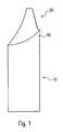
- the dental implantconsists of an anchoring part 10 for anchoring the dental implant in the bone and an abutment 20 on which the Supra structure is placed in a known manner.
- the anchoring parthas special sections 40 and in particular in the region of the transition between anchoring part 10 and abutment 20, which are made on the green body by sandblasting according to the patient data.
- a dental implantis inserted in a bone 1.
- a cylindrical or (in the case of a correspondingly different shape) slightly conical hole in the bone 1is drilled into the bone 1 and the dental implant is inserted.
- a channel 11, in particular a cylindrical boreis introduced in the dental implant, in which a Einklopfx 12 can be used.
- This Einklopfx 12serves to hold the dental implant and by means of a Hämmerchens (see Fig. 3 ).
- this embodiment of the inventionin which the channel 11 for receiving the Einklopfloches 12 is also passed through the abutment 20, then, if (as in Fig. 2 shown) in the upper jaw an implant should be used, since there usually an angled abutment is necessary.
- the shapingtakes place here via DVT / CT and computer in such a way that the patient is "measured” and a suitable computer implantation is used to design an optimally fitting dental implant.
- the real bodyis then made of zirconium oxide in the dental laboratory.
- an anchoring part 10is provided in accordance with the specifications obtained by digital recordings with special areas 4 such that the osteogenesis takes place or is promoted in the precalculated areas.
- the thus formed anchoring part 10is then inserted into the bone, whereupon the channel 11 is closed by means of a silicone plug 13. After inserting the Gums closed over the implant. This closure results in improved bone formation when the implant protrudes into the oral cavity during the healing phase. By the silicone plug 13 ingrowth of the gums in the channel 11 is prevented.
- the implantAfter the healing phase of implant and bone, the implant must be exposed again by means of a longitudinal cut or punched hole (depending on the situation), as in Fig. 5 is shown.
- the abutment 20 made of zirconium oxide with a holding piece 21is integrally cemented with the aid of a Justierrschreibchens 4 made of plastic in the anchoring part 10 and in the provided there channel 11, wherein the made of plastic Justierröhren particular ensures a blood-free working surface.
- After removal of the cement residuescan be cemented directly to the abutment 20 a temporary.
- a particular advantage hereis that a transfer impression of the implant is not necessary, since all parts in the dental laboratory can be prepared in advance on the basis of supplied data, which include models with mucosal thickness measurement or DVT / CT data.
- connection between anchoring part 10 and abutment 20has a so-called “platform switch", as this in the 6 and 7 is indicated because now an adhesive bond between the abutment 20 and the anchoring part 10 has arisen, which can cause tissue irritation.
- Thisis known in implantology, with investigations showing that the bone can retract to about 1.6 to 2 mm from this source of interference. Therefore, the distance from the adhesive gap to the bone to about 1.5 to 2 mm to lay (see double arrow in Fig. 7 ) to prevent bone loss around the implant.
Landscapes
- Health & Medical Sciences (AREA)
- Life Sciences & Earth Sciences (AREA)
- Veterinary Medicine (AREA)
- Epidemiology (AREA)
- Dentistry (AREA)
- Animal Behavior & Ethology (AREA)
- General Health & Medical Sciences (AREA)
- Public Health (AREA)
- Oral & Maxillofacial Surgery (AREA)
- Orthopedic Medicine & Surgery (AREA)
- Engineering & Computer Science (AREA)
- Ceramic Engineering (AREA)
- Biomedical Technology (AREA)
- Developmental Biology & Embryology (AREA)
- Dental Prosthetics (AREA)
- Prostheses (AREA)
- Materials For Medical Uses (AREA)
- Dental Preparations (AREA)
Abstract
Description
Translated fromGermanDie Erfindung betrifft ein Dentalimplantat nach dem Oberbegriff des Patentanspruches 1.The invention relates to a dental implant according to the preamble of
Dentalimplantate werden seit einiger Zeit erfolgreich eingesetzt. In vielen Fällen wird als Material Titan verwendet, mit dem eine sichere Verbundosteogenese erreicht werden kann. Allerdings sind optische Probleme nur durch sehr aufwändige Maßnahmen zu vermeiden.Dental implants have been used successfully for some time. In many cases, the material used is titanium, with which secure composite osteogenesis can be achieved. However, optical problems can only be avoided by very costly measures.
Aus der
Aus der
Der Erfindung liegt die Aufgabe zu Grunde, ein Dentalimplantat der eingangs genannten Art dahin gehend weiter zu bilden bzw. eine Herstellungsverfahren hierfür aufzuzeigen, dass eine optimale Anpassung bei leichter Einsetzbarkeit und guten Dauereigenschaften sichergestellt wird.The invention is based on the object of further developing a dental implant of the type mentioned at the outset, or of demonstrating a production method therefor, that optimum adaptation is ensured with ease of use and good permanent properties.
Diese Aufgabe wird bei einem Dentalimplantat für einen Patienten, umfassend ein Verankerungsteil zum Verankern des Dentalimplantats im Knochen und ein Abutment zur Befestigung einer Krone oder dergleichen Suprakonstruktion, das mit dem Verankerungsteil verbunden oder verbindbar ist, wobei das Verankerungsteil und das Abutment auf Zirkonoxidbasis gefertigt sind, dadurch gelöst, dass das Verankerungsteil und/oder das Abutment Sonderabschnitte entsprechend individuellen Abmessungen von Knochen und/oder Zahnfleisch des Patienten aufweist, welche eine aufgerauhte und zur Verwachsung mit dem Knochen und/oder zum Einwachsen in das Zahnfleisch ausgebildete Oberfläche aufweisen, wobei die Sonderabschnitte am Grünkörper vor dessen abschließendem Sintern gefertigt sind.This object is achieved in a dental implant for a patient, comprising an anchoring part for anchoring the dental implant in the bone and an abutment for fixing a crown or the like superstructure, which with the anchoring part is connected or connectable, wherein the anchoring part and the abutment are made of zirconium oxide, achieved in that the anchoring part and / or the abutment has special sections corresponding to individual dimensions of the patient's bones and / or gums, which has a roughened and to adhere to the bone and / or have for growth into the gum surface formed, wherein the special sections are made on the green body before its final sintering.
Ein wesentlicher Punkt der Erfindung liegt darin, dass nur grob konfektionierte Grünkörper (Verankerungsteil und Abutment) vorgehalten werden müssen, während die für die Verbundosteogenese notwendige Oberflächenbearbeitung nach entsprechenden Vermessungsvorgaben (tomographische Aufnahmen) im Dentallabor vorgenommen werden kann. Dadurch, dass am Grünkörper gearbeitet wird, kann eine optimale Oberflächenaufrauhung stattfinden, die am fertig gesinterten Produkt aufgrund dessen großer Härte fast unmöglich ist. Durch diese individuelle Oberflächengestaltung können auch Knochendefekte durch Osteogenese in optimaler Weise behoben werden.An essential point of the invention is that only coarsely assembled green body (anchoring part and abutment) must be kept, while necessary for the composite osteogenesis surface treatment can be made according to surveying specifications (tomographic images) in the dental laboratory. The fact that working on the green body, an optimal surface roughening take place, which is almost impossible on the finished sintered product due to its high hardness. Through this individual surface design, bone defects can be corrected by osteogenesis in an optimal way.
Vorzugsweise werden die Sonderabschnitte auf der Oberfläche des Grünkörpers mittels Sandstrahlen aufgerauht. Diese Technik ist sehr einfach und führt zu einer die Osteogenese optimal fördernden Oberflächenrauhigkeit.Preferably, the special sections are roughened on the surface of the green body by means of sandblasting. This technique is very simple and leads to an optimal osteogenesis surface roughness.
Das Verankerungsteil und das Abutment sind bei einer bevorzugten Ausführungsform der Erfindung einstückig ausgebildet. Dadurch wird nicht nur eine optimale Haltbarkeit erzielt, vielmehr ergibt sich auch ein in ästhetischer Hinsicht optimales Implantat.The anchoring part and the abutment are integrally formed in a preferred embodiment of the invention. As a result, not only optimum durability is achieved, but also results in an aesthetically optimal implant.
Der Übergangsbereich zwischen dem Verankerungsteil und dem Abutment wird vorzugsweise entsprechend den individuellen Abmessungen des Knochens des Patienten insbesondere durch Bearbeitung des Grünkörpers gefertigt. Dadurch kann den individuellen Gegebenheiten besonders gut Rechnung getragen werden.The transition region between the anchoring part and the abutment is preferably made according to the individual dimensions of the bone of the patient, in particular by processing the green body. As a result, the individual circumstances are particularly well taken into account.
Das Verankerungsteil weist bei einer Ausführungsform der Erfindung eine zum Einklopfen in eine zylindrische oder konische Bohrung im Knochen ausgebildete Oberfläche und eine konzentrische Bohrung zur Aufnahme eines Stiftes auf, zum Halten, Führen und Einklopfen des Verankerungsteils. Dadurch ist ein besonders exaktes Einbringen des Implantates möglich, ohne dass allzu aufwändige Schablonen oder Justiereinrichtungen verwendet werden müssten. Bei einer einstückigen Ausbildung von Verankerungsteil und Abutment führt die Bohrung vorzugsweise durch das Abutment in das Verankerungsteil hinein, so dass die exakte Einbringung des Implantates ermöglicht wird.The anchoring part, in one embodiment of the invention, has a surface for knocking into a cylindrical or conical bore in the bone and a concentric bore for receiving a pin for holding, guiding and tapping the anchoring part. As a result, a particularly precise insertion of the implant is possible without the need for overly complex stencils or adjusting devices. In a one-piece design of anchoring part and abutment, the bore preferably leads through the abutment into the anchoring part, so that the exact introduction of the implant is made possible.
Das Verankerungsteil wird bei einer Ausführungsform der Erfindung vorzugsweise getrennt vom Abutment gefertigt und weist eine koaxiale Bohrung auf, die einerseits wieder zum Einklopfen mittels eines Stiftes dient und die andererseits zum Befestigen des mit einem entsprechenden Stift versehenen Abutments verwendbar ist.The anchoring part is preferably made separately from the abutment in one embodiment of the invention and has a coaxial bore, which on the one hand serves again for knocking by means of a pin and which on the other hand can be used for fastening the abutment provided with a corresponding pin.
Die Bohrung ist derart ausgebildet und weist insbesondere an ihrem oberen Ende eine Aufweitung auf, dass sie durch einen Silikonstopfen während einer Zeitdauer verschließbar ist, in welcher das Zahnfleisch nach dem Einklopfen des Verankerungsteil in den Knochen heilt.The bore is formed and has a widening, in particular at its upper end, that it can be closed by a silicone plug during a period of time in which the gums heal after knocking the anchoring part into the bone.
Weiterhin wird die Aufgabe durch ein Verfahren zum Herstellen eines Dentalimplantates gelöst, umfassend die Schritte
- Herstellen einer 3-dimensionalen, digitalen Abbildung eines Bereiches von Knochen und Zahnfleisch eines Patienten, in welchen das Dentalimplantat einzusetzen ist,
- Anfertigen einer digitalen Repräsentation des Dentalimplantates,
- Fräsen eines Zirkonoxid-Grünkörpers entsprechend dem Dentalimplantat mit Übermaß zur Kompensation einer Schrumpfung,
- Sandstrahlen von Sonderabschnitten des Grünkörpers entsprechend der digitalen Abbildung und der digitalen Repräsentation,
- Gegebenenfalls Anbringen von Bohrungen im Grünkörper und
- Brennen/Sintern des bearbeiteten Grünkörpers.
- Producing a 3-dimensional, digital image of a region of bone and gums of a patient in which the dental implant is to be inserted,
- Making a digital representation of the dental implant,
- Milling a zirconia green body according to the dental implant with oversize to compensate for shrinkage,
- Sandblasting special sections of the green body according to the digital imaging and the digital representation,
- If necessary, attach holes in the green body and
- Burning / sintering of the processed green body.
Nachfolgend wird die Erfindung anhand von Abbildungen näher erläutert. Hierbei zeigen
Fig. 1 eine Seitenansicht eines Dentalimplantats,Fig. 2 eine schematisierte Darstellung eines eingesetzten Dentalimplantates mit Darstellung von Knochen und Zahnfleisch,Fig. 3 eine Darstellung zur Erläuterung des Einklopfens des Dentalimplantates,Fig. 4 eine schematisierte Darstellung eines eingesetzten Verankerungsteils mit Knochen und Zahnfleisch,Fig. 5 eine Darstellung zur Erläuterung des Einsetzens eines Abutments in das Verankerungsteil,Fig. 6 eine Darstellung der Anordnung im vollständig eingesetzten Zustand undFig. 7 eine vergrößerte Darstellung des Abschnittes XII ausFig. 6 .
Fig. 1 a side view of a dental implant,Fig. 2 a schematic representation of a dental implant used with representation of bone and gums,Fig. 3 a representation for explaining the tapping of the dental implant,Fig. 4 a schematic representation of an inserted anchoring part with bone and gums,Fig. 5 a representation for explaining the insertion of an abutment in the anchoring part,Fig. 6 a representation of the arrangement in the fully inserted state andFig. 7 an enlarged view of the section XII fromFig. 6 ,
In der nachfolgenden Beschreibung werden für gleiche und gleich wirkende Teile dieselben Bezugsziffern verwendet.In the following description, the same reference numerals are used for the same and like parts.
Wie in
In
Abschließend wird die Suprakonstruktion 30 aufgesetzt.Finally, the
Besonders vorteilhaft ist diese Ausführungsform der Erfindung, bei welcher der Kanal 11 zur Aufnahme des Einklopfstiftes 12 auch durch das Abutment 20 hindurchgeführt ist, dann, wenn (wie in
Bei der in
Nach der Einheilphase von Implantat und Knochen muss das Implantat mittels eines Längsschnittes oder Stanzloches (situationsabhängig) wieder freigelegt werden, wie dies in
Die Verbindung zwischen Verankerungsteil 10 und Abutment 20 hat einen sogenannten "Platform-Switch", wie dieser in den
Bei der hier gezeigten Ausführungsform der Erfindung ist noch als weiterer Vorteil zu erwähnen, dass durch die rotationssymmetrische Ausbildung des Verankerungsteils 10 (ohne Gewinde) noch kleine Rotationsänderungen während des Einsetzens vom Zahnarzt vorgenommen werden können, wobei das Einklopfen mittels der hier gezeigten Anordnung mit einem konzentrischen Kanal 11 eine besonders einfache und bei stark abgewinkeltem Abutment verwendbare Behandlungsmethode ist.In the embodiment of the invention shown here is yet to mention a further advantage that can be made by the rotationally symmetrical design of the anchoring part 10 (without thread) even small changes in rotation during insertion by the dentist, the knocking by means of the arrangement shown here with a
- 11
- Knochenbone
- 22
- Zahnfleischgums
- 44
- JustierröhrchenJustierröhrchen
- 1010
- Verankerungsteilanchoring part
- 1111
- Kanalchannel
- 1212
- EinklopfstiftEinklopfstift
- 1313
- Silikonstopfensilicone plugs
- 2020
- Abutmentabutment
- 2121
- Haltestiftretaining pin
- 3030
- Suprakonstruktionsuperstructure
- 4040
- Sonderabschnittspecial section
Claims (8)
- Dental implant for a patient, comprising
an anchorage part (10) for anchoring the dental implant in the bone and an abutment (20) for fastening a crown or superconstruction (30) of this kind which is or can be connected to the anchorage part (10), wherein the anchorage part (10) and the abutment are zirconium oxide-based,
characterised in that
the anchorage part (10) and/or the abutment (20) have/has special portions (40) which have a roughened surface which is formed to fuse with bone and/or to grow into the gums, wherein the special portions (40) are made on the green compact before this is finally sintered. - Dental implant according to Claim 1,
characterised in that
the special portions (40) are roughened by means of sandblasting. - Dental implant according to any one of the preceding Claims,
characterised in that
the transition region between the anchorage part (10) and the abutment (20) is made according to individual dimensions of the bone of the patient, in particular by machining the green compact. - Dental implant according to any one of the preceding Claims,
characterised in that
the anchorage part and the abutment are formed in one piece. - Dental implant according to any one of the preceding Claims,
characterised in that
the anchorage part (10) has a surface which is formed for driving into a cylindrical or conical hole in the bone, and a concentric hole (11) for receiving a pin (12) for retaining, guiding and driving in the anchorage part (10). - Dental implant according to Claim 5,
characterised in that,
if the anchorage part (10) and the abutment (20) are formed in one piece, the hole (11) reaches through the abutment (20) into the anchorage part (10). - Dental implant according to any one of Claims 1 - 3,
characterised in that
the anchorage part (10) is made separate from the abutment (20) and has a coaxial hole (11) for fastening the abutment (20) provided with a corresponding pin (1), which hole can be closed by a silicone plug (13). - Method for producing a dental implant, comprising the steps- producing a 3-dimensional, digital image of a region of the bone and gums of a patient in which the dental implant is to be inserted,- producing a digital representation of the dental implant,- milling a zirconium oxide green compact corresponding to the dental implant with an oversize to compensate for shrinkage,- sandblasting special portions of the green compact according to the digital image and the digital representation,- optionally making holes in the green compact and- firing/sintering the machined green compact.
Applications Claiming Priority (2)
| Application Number | Priority Date | Filing Date | Title |
|---|---|---|---|
| DE102004027959ADE102004027959B4 (en) | 2004-06-08 | 2004-06-08 | Dental implant and method for its production |
| PCT/EP2005/006010WO2005120386A1 (en) | 2004-06-08 | 2005-06-03 | Zirconium oxide-based dental implant and method for producing said dental implant |
Publications (4)
| Publication Number | Publication Date |
|---|---|
| EP1761196A1 EP1761196A1 (en) | 2007-03-14 |
| EP1761196B1true EP1761196B1 (en) | 2008-08-27 |
| EP1761196B9 EP1761196B9 (en) | 2009-08-12 |
| EP1761196B2 EP1761196B2 (en) | 2011-06-15 |
Family
ID=34968681
Family Applications (1)
| Application Number | Title | Priority Date | Filing Date |
|---|---|---|---|
| EP05745593AExpired - LifetimeEP1761196B2 (en) | 2004-06-08 | 2005-06-03 | Zirconium oxide-based dental implant and method for producing said dental implant |
Country Status (8)
| Country | Link |
|---|---|
| US (2) | US8048345B2 (en) |
| EP (1) | EP1761196B2 (en) |
| AT (1) | ATE406144T1 (en) |
| DE (3) | DE102004027959B4 (en) |
| DK (1) | DK1761196T4 (en) |
| ES (1) | ES2313347T5 (en) |
| PT (1) | PT1761196E (en) |
| WO (1) | WO2005120386A1 (en) |
Families Citing this family (43)
| Publication number | Priority date | Publication date | Assignee | Title |
|---|---|---|---|---|
| US20060163774A1 (en)* | 2005-01-25 | 2006-07-27 | Norbert Abels | Methods for shaping green bodies and articles made by such methods |
| US20060166159A1 (en) | 2005-01-25 | 2006-07-27 | Norbert Abels | Laser shaping of green metal body used in manufacturing an orthodontic bracket |
| DE102005008273A1 (en)* | 2005-02-22 | 2006-08-24 | Mundorf, Sönke, Dr. | Tooth implant comprises a bone anchoring part having an outer surface for anchoring in the jawbone and formed as a tissue anchoring part and a tooth alignment part fixed to the bone anchoring part on which a crown is fixed |
| DE06785810T1 (en) | 2005-06-30 | 2016-03-10 | Biomet 3I, Llc | METHOD FOR PRODUCING COMPONENTS OF A DENTAL IMPLANT |
| AT502881B1 (en)* | 2005-10-05 | 2007-08-15 | Pirker Wolfgang Ddr | DENTAL IMPLANT |
| US11219511B2 (en) | 2005-10-24 | 2022-01-11 | Biomet 3I, Llc | Methods for placing an implant analog in a physical model of the patient's mouth |
| DE102006062712A1 (en)* | 2006-02-03 | 2007-08-30 | Maxon Motor Gmbh | Implant and method of making an implant |
| DE102006005034A1 (en)* | 2006-02-03 | 2007-08-16 | Maxon Motor Gmbh | Manufacturing method of implant designed for incorporation in bone by powder injection molding of binder, involves increasing upper surface hardness before closing sinters, while upper surface is roughened in green part |
| EP2292178A1 (en) | 2006-02-28 | 2011-03-09 | Straumann Holding AG | Two-part implant |
| DE102006033547A1 (en)* | 2006-07-20 | 2008-01-24 | Dieter Keller | implant |
| JP2010513330A (en)* | 2006-12-22 | 2010-04-30 | トーメン メディカル アーゲー | Dental implant and manufacturing method thereof |
| DE102007002144A1 (en)* | 2007-01-15 | 2008-07-17 | Aepsilon Rechteverwaltungs Gmbh | Procedures relating to implants and a computer-readable medium and a computer |
| DE102007026325B4 (en)* | 2007-04-20 | 2019-05-09 | Zv3 - Zircon Vision Gmbh | Artificial dentures |
| DE102007038958A1 (en) | 2007-08-15 | 2009-02-19 | Inocermic Gesellschaft für innovative Keramik mbH | Process for the production of implants and components by direct shaping |
| DE102007057917B3 (en)* | 2007-12-01 | 2009-05-07 | Hans-Jürgen Moje | Roughening the surface of zirconium oxide ceramic implants, e.g. for dental applications, involves clamping the formed, presintered implant in a rotating holder and grit-blasting with zircon grains |
| DE202008010483U1 (en) | 2008-08-06 | 2008-10-16 | Moje, Hans-Jürgen | Structure for endoprostheses |
| US20110127700A1 (en)* | 2008-08-07 | 2011-06-02 | Deru Gmbh | Method for producing a ceramic component |
| DE102008037859B4 (en)* | 2008-08-15 | 2012-09-27 | Oechsler Ag | Dental implant |
| ES2423032T3 (en) | 2008-12-01 | 2013-09-17 | Straumann Holding Ag | Fixing pin |
| DE102009003650A1 (en)* | 2009-03-20 | 2010-09-30 | Degudent Gmbh | Method of making an abutment |
| DE102009001782A1 (en) | 2009-03-24 | 2010-09-30 | Sirona Dental Systems Gmbh | gingivaformer |
| US8246870B2 (en)* | 2009-06-01 | 2012-08-21 | Layton Grant H | Dental implant system and method of use |
| US20110262882A1 (en)* | 2010-04-26 | 2011-10-27 | William Nordquist | Natural Tooth Replacement (NTR): An Alternative to Tooth Root Canal (RCT) Therapy and Immediate Root-Form Implant Placement Into Extraction Socket |
| US20120237902A1 (en)* | 2011-03-17 | 2012-09-20 | Joseph Maniscalco Dds Pc | Techniques for providing custom-formed implants |
| DE102011015299A1 (en) | 2011-03-21 | 2012-09-27 | Zm Präzisionsdentaltechnik Gmbh | Dental implant |
| FR2982478B1 (en)* | 2011-11-15 | 2014-01-10 | Robert Fromental | DENTAL IMPLANT FOR IMMEDIATE POST-EXTRACTIONAL IMPLANTATION |
| US10507081B2 (en) | 2012-01-10 | 2019-12-17 | Esthetic Implant Solutions, Llc | Methods for taking an impression or scanning without requiring removal of a temporary healing abutment |
| US10568720B2 (en) | 2012-01-10 | 2020-02-25 | Estetic Implant Solutions, LLC | Dental implants with markers for determining three-dimensional positioning |
| US10016260B2 (en) | 2012-01-10 | 2018-07-10 | Mark H. Blaisdell | Anatomical healing abutments, kits, and methods |
| US11253345B2 (en) | 2012-01-10 | 2022-02-22 | Esthetic Implant Solutions, Llc | Methods for integrating scans including 3D cone beam scan for positioning of implant and fabrication of dental prosthesis |
| US9895209B2 (en) | 2012-01-10 | 2018-02-20 | Mark H. Blaisdell | Casting jig including elongate handle for chair-side manufacture of customizable sculptable anatomical healing caps, and method for forming bis-acrylic crown |
| US9572640B2 (en) | 2012-10-02 | 2017-02-21 | Mark H. Blaisdell | Casting jig for chair-side manufacture of customizable sculptable anatomical healing caps |
| US10595970B2 (en) | 2012-01-10 | 2020-03-24 | Esthetic Implant Solutions, Llc | Bonding of soft gingival tissues with anatomical and other dental prostheses |
| US10709525B2 (en) | 2012-01-10 | 2020-07-14 | Esthetic Implant Solutions, Llc | Methods for taking an oral scan without requiring removal of a temporary healing abutment |
| US8628327B1 (en) | 2012-10-02 | 2014-01-14 | Mark H. Blaisdell | Casting jig for chair-side manufacture of customizable sculptable anatomical healing caps |
| US20220151742A1 (en) | 2012-01-10 | 2022-05-19 | Esthetic Implant Solutions, Llc | Methods for integrating scans including 3d cone beam scan for positioning of implant and fabrication of dental prosthesis |
| US9168110B2 (en) | 2012-05-29 | 2015-10-27 | Biomet 3I, Llc | Dental implant system having enhanced soft-tissue growth features |
| EP2892462A1 (en) | 2012-09-04 | 2015-07-15 | 3M Innovative Properties Company | Method of producing a dental restoration |
| KR101469833B1 (en)* | 2013-12-06 | 2014-12-08 | 오상훈 | Link for customized zirconia abutment of dental implant |
| USD765856S1 (en) | 2014-02-14 | 2016-09-06 | Vita Zahnfabrik H. Rauter Gmbh & Co. Kg | Dental implant |
| KR101715474B1 (en)* | 2015-05-18 | 2017-03-10 | 오상훈 | The link of customized zirconia abutment for droping out and node of zirconia coping |
| US10449019B2 (en) | 2016-07-20 | 2019-10-22 | Natural Dental Implants Ag | Systems and methods for securing a dental implant |
| US11559379B2 (en) | 2018-04-12 | 2023-01-24 | Esthetic Implant Solutions, Llc | Dental implants with markers for determining three-dimensional positioning |
Family Cites Families (17)
| Publication number | Priority date | Publication date | Assignee | Title |
|---|---|---|---|---|
| US4854873A (en)* | 1987-10-13 | 1989-08-08 | Hall Surgical Division Of Zimmer, Inc. | Oral implant |
| US4853353A (en)* | 1988-01-25 | 1989-08-01 | Allied-Signal Inc. | Method for preventing low-temperature degradation of tetragonal zirconia containing materials |
| US4891343A (en)* | 1988-08-10 | 1990-01-02 | W. R. Grace & Co.-Conn. | Stabilized zirconia |
| CH688894A5 (en)* | 1993-05-07 | 1998-05-15 | Metoxit Ag | Using yttrium-stabilized zirconium oxide for the production of semifinished products for prostheses through dense sintering |
| DE19530981A1 (en)* | 1995-08-23 | 1997-02-27 | Marcus Dr Simon | Prefabricated ceramic event structure for forming artificial crown stumps for prosthetic restorations |
| US20050023710A1 (en)* | 1998-07-10 | 2005-02-03 | Dmitri Brodkin | Solid free-form fabrication methods for the production of dental restorations |
| US6354836B1 (en)* | 1998-08-20 | 2002-03-12 | Jeneric/Pentron, Inc. | Methods of producing dental restorations using CAD/CAM and manufactures thereof |
| US7655586B1 (en)* | 2003-05-29 | 2010-02-02 | Pentron Ceramics, Inc. | Dental restorations using nanocrystalline materials and methods of manufacture |
| US7011689B2 (en)* | 1998-12-09 | 2006-03-14 | Societe Europeenne Des Produits Refractaires | Melted alumina-zirconia ceramic grains, abrasive tools and refractory parts produced from said grains |
| US6217333B1 (en)* | 2000-05-09 | 2001-04-17 | Carlo Ercoli | Dental implant for promoting reduced interpoximal resorption |
| DE10065971A1 (en)* | 2000-11-25 | 2002-06-06 | Hermsdorfer Inst Tech Keramik | Process for the production of ceramic dentures and then high-strength ceramic dentures |
| DE10159683A1 (en)* | 2001-11-30 | 2003-06-18 | Michael Gahlert | Dantalimplantat |
| US6655961B2 (en)* | 2001-12-03 | 2003-12-02 | Richard Day Cottrell | Modified dental implant fixture |
| FR2843957B1 (en)* | 2002-08-28 | 2004-10-22 | Ondeo Degremont | WASTE DRYING PLANT, ESPECIALLY WATER PURIFICATION SLUDGE |
| EP1396237A1 (en)* | 2002-09-05 | 2004-03-10 | Elephant Dental B.V. | Strengthened ceramic restoration |
| WO2004103203A2 (en)* | 2003-05-16 | 2004-12-02 | Nobel Biocare Services Ag | Dental implant system |
| PT1529498E (en)* | 2003-11-05 | 2014-09-17 | Dentsply Implants Mfg Gmbh | Multi part non metal implant |
- 2004
- 2004-06-08DEDE102004027959Apatent/DE102004027959B4/ennot_activeExpired - Lifetime
- 2004-06-08DEDE202004020338Upatent/DE202004020338U1/ennot_activeExpired - Lifetime
- 2005
- 2005-06-03EPEP05745593Apatent/EP1761196B2/ennot_activeExpired - Lifetime
- 2005-06-03DKDK05745593.3Tpatent/DK1761196T4/enactive
- 2005-06-03WOPCT/EP2005/006010patent/WO2005120386A1/enactiveIP Right Grant
- 2005-06-03USUS11/570,257patent/US8048345B2/ennot_activeExpired - Lifetime
- 2005-06-03ESES05745593Tpatent/ES2313347T5/ennot_activeExpired - Lifetime
- 2005-06-03ATAT05745593Tpatent/ATE406144T1/enactive
- 2005-06-03PTPT05745593Tpatent/PT1761196E/enunknown
- 2005-06-03DEDE502005005202Tpatent/DE502005005202D1/ennot_activeExpired - Lifetime
- 2011
- 2011-10-28USUS13/283,639patent/US20120107774A1/ennot_activeAbandoned
Also Published As
| Publication number | Publication date |
|---|---|
| US20080057475A1 (en) | 2008-03-06 |
| US8048345B2 (en) | 2011-11-01 |
| ES2313347T3 (en) | 2009-03-01 |
| EP1761196A1 (en) | 2007-03-14 |
| DK1761196T4 (en) | 2011-09-26 |
| DE502005005202D1 (en) | 2008-10-09 |
| DK1761196T3 (en) | 2008-12-15 |
| WO2005120386A1 (en) | 2005-12-22 |
| EP1761196B2 (en) | 2011-06-15 |
| DE102004027959B4 (en) | 2009-11-12 |
| DE102004027959A1 (en) | 2006-01-05 |
| PT1761196E (en) | 2008-12-03 |
| US20120107774A1 (en) | 2012-05-03 |
| ES2313347T5 (en) | 2011-11-15 |
| ATE406144T1 (en) | 2008-09-15 |
| EP1761196B9 (en) | 2009-08-12 |
| DE202004020338U1 (en) | 2005-05-12 |
Similar Documents
| Publication | Publication Date | Title |
|---|---|---|
| EP1761196B1 (en) | Zirconium oxide-based dental implant and method for producing said dental implant | |
| EP1855610B1 (en) | Two-part dental implant system | |
| DE102012201092B4 (en) | Dental implant system | |
| EP1617783B1 (en) | Dental implant | |
| DE102010021601A1 (en) | analog implant | |
| WO2008006868A1 (en) | Tooth implant with machinable construction | |
| DE202012102746U1 (en) | Dental implant abutment system | |
| DE102013014660A1 (en) | Supraconstruction for an implant system, blank for its manufacture and associated screwdriver | |
| WO2014012973A2 (en) | Dental implant abutment system | |
| DE102005006979A1 (en) | Ceramic endosseous dental implant | |
| WO2008086978A1 (en) | Method relating to implants, and a machine-readable medium and a computer | |
| DE20023670U1 (en) | Manufactured teeth for placement on prepared natural teeth or fragments | |
| EP2742905A1 (en) | Dental implant | |
| EP1786354B1 (en) | Dental implant system | |
| DE202008007189U1 (en) | Abutment for a screw implant in a jawbone | |
| EP3545904B1 (en) | Method for producing a working model for dental use from a digitised replication | |
| DE102006045188B4 (en) | Construction for a two-part dental implant | |
| DE202006013265U1 (en) | Dental implant, comprising slightly bent conical upper part with several v-shaped anchoring segments | |
| DE102007025164A1 (en) | Methods and apparatus for creating a model of a patient's dentition | |
| EP2845562A1 (en) | Implant and system for dental prosthesis | |
| DE10331524A1 (en) | Dental implant | |
| EP2331008B1 (en) | Implant system for fixing artificial teeth | |
| CH707689A1 (en) | Zahnimplatat. | |
| DE102004034800B4 (en) | Body for dental crown abutment system | |
| EP4082476A1 (en) | Dental implant system |
Legal Events
| Date | Code | Title | Description |
|---|---|---|---|
| PUAI | Public reference made under article 153(3) epc to a published international application that has entered the european phase | Free format text:ORIGINAL CODE: 0009012 | |
| 17P | Request for examination filed | Effective date:20070104 | |
| AK | Designated contracting states | Kind code of ref document:A1 Designated state(s):AT BE BG CH CY CZ DE DK EE ES FI FR GB GR HU IE IS IT LI LT LU MC NL PL PT RO SE SI SK TR | |
| 17Q | First examination report despatched | Effective date:20070521 | |
| DAX | Request for extension of the european patent (deleted) | ||
| GRAP | Despatch of communication of intention to grant a patent | Free format text:ORIGINAL CODE: EPIDOSNIGR1 | |
| GRAS | Grant fee paid | Free format text:ORIGINAL CODE: EPIDOSNIGR3 | |
| GRAA | (expected) grant | Free format text:ORIGINAL CODE: 0009210 | |
| AK | Designated contracting states | Kind code of ref document:B1 Designated state(s):AT BE BG CH CY CZ DE DK EE ES FI FR GB GR HU IE IS IT LI LT LU MC NL PL PT RO SE SI SK TR | |
| REG | Reference to a national code | Ref country code:GB Ref legal event code:FG4D Free format text:NOT ENGLISH | |
| REG | Reference to a national code | Ref country code:CH Ref legal event code:EP | |
| REG | Reference to a national code | Ref country code:IE Ref legal event code:FG4D Free format text:LANGUAGE OF EP DOCUMENT: GERMAN | |
| REF | Corresponds to: | Ref document number:502005005202 Country of ref document:DE Date of ref document:20081009 Kind code of ref document:P | |
| REG | Reference to a national code | Ref country code:CH Ref legal event code:NV Representative=s name:TROESCH SCHEIDEGGER WERNER AG | |
| REG | Reference to a national code | Ref country code:SE Ref legal event code:TRGR | |
| REG | Reference to a national code | Ref country code:PT Ref legal event code:SC4A Free format text:AVAILABILITY OF NATIONAL TRANSLATION Effective date:20081120 | |
| REG | Reference to a national code | Ref country code:DK Ref legal event code:T3 | |
| PG25 | Lapsed in a contracting state [announced via postgrant information from national office to epo] | Ref country code:LT Free format text:LAPSE BECAUSE OF FAILURE TO SUBMIT A TRANSLATION OF THE DESCRIPTION OR TO PAY THE FEE WITHIN THE PRESCRIBED TIME-LIMIT Effective date:20080827 Ref country code:IS Free format text:LAPSE BECAUSE OF FAILURE TO SUBMIT A TRANSLATION OF THE DESCRIPTION OR TO PAY THE FEE WITHIN THE PRESCRIBED TIME-LIMIT Effective date:20081227 | |
| PG25 | Lapsed in a contracting state [announced via postgrant information from national office to epo] | Ref country code:SI Free format text:LAPSE BECAUSE OF FAILURE TO SUBMIT A TRANSLATION OF THE DESCRIPTION OR TO PAY THE FEE WITHIN THE PRESCRIBED TIME-LIMIT Effective date:20080827 | |
| REG | Reference to a national code | Ref country code:ES Ref legal event code:FG2A Ref document number:2313347 Country of ref document:ES Kind code of ref document:T3 | |
| PLBI | Opposition filed | Free format text:ORIGINAL CODE: 0009260 | |
| REG | Reference to a national code | Ref country code:IE Ref legal event code:FD4D | |
| 26 | Opposition filed | Opponent name:MAXON MOTOR GMBH Effective date:20090316 | |
| PG25 | Lapsed in a contracting state [announced via postgrant information from national office to epo] | Ref country code:IE Free format text:LAPSE BECAUSE OF FAILURE TO SUBMIT A TRANSLATION OF THE DESCRIPTION OR TO PAY THE FEE WITHIN THE PRESCRIBED TIME-LIMIT Effective date:20080827 Ref country code:BG Free format text:LAPSE BECAUSE OF FAILURE TO SUBMIT A TRANSLATION OF THE DESCRIPTION OR TO PAY THE FEE WITHIN THE PRESCRIBED TIME-LIMIT Effective date:20081127 | |
| PG25 | Lapsed in a contracting state [announced via postgrant information from national office to epo] | Ref country code:SK Free format text:LAPSE BECAUSE OF FAILURE TO SUBMIT A TRANSLATION OF THE DESCRIPTION OR TO PAY THE FEE WITHIN THE PRESCRIBED TIME-LIMIT Effective date:20080827 Ref country code:CZ Free format text:LAPSE BECAUSE OF FAILURE TO SUBMIT A TRANSLATION OF THE DESCRIPTION OR TO PAY THE FEE WITHIN THE PRESCRIBED TIME-LIMIT Effective date:20080827 Ref country code:RO Free format text:LAPSE BECAUSE OF FAILURE TO SUBMIT A TRANSLATION OF THE DESCRIPTION OR TO PAY THE FEE WITHIN THE PRESCRIBED TIME-LIMIT Effective date:20080827 | |
| PLBI | Opposition filed | Free format text:ORIGINAL CODE: 0009260 | |
| PLAX | Notice of opposition and request to file observation + time limit sent | Free format text:ORIGINAL CODE: EPIDOSNOBS2 | |
| NLR1 | Nl: opposition has been filed with the epo | Opponent name:MAXON MOTOR GMBH | |
| PLAB | Opposition data, opponent's data or that of the opponent's representative modified | Free format text:ORIGINAL CODE: 0009299OPPO | |
| 26 | Opposition filed | Opponent name:MAXON MOTOR GMBH Effective date:20090316 Opponent name:STRAUMANN HOLDING AG Effective date:20090527 | |
| PG25 | Lapsed in a contracting state [announced via postgrant information from national office to epo] | Ref country code:EE Free format text:LAPSE BECAUSE OF FAILURE TO SUBMIT A TRANSLATION OF THE DESCRIPTION OR TO PAY THE FEE WITHIN THE PRESCRIBED TIME-LIMIT Effective date:20080827 | |
| R26 | Opposition filed (corrected) | Opponent name:MAXON MOTOR GMBH Effective date:20090316 Opponent name:STRAUMANN HOLDING AG Effective date:20090527 | |
| PLAB | Opposition data, opponent's data or that of the opponent's representative modified | Free format text:ORIGINAL CODE: 0009299OPPO | |
| NLR1 | Nl: opposition has been filed with the epo | Opponent name:MAXON MOTOR GMBH Opponent name:STRAUMANN HOLDING AG | |
| PLBB | Reply of patent proprietor to notice(s) of opposition received | Free format text:ORIGINAL CODE: EPIDOSNOBS3 | |
| NLR1 | Nl: opposition has been filed with the epo | Opponent name:MAXON MOTOR GMBH Opponent name:STRAUMANN HOLDING AG | |
| PG25 | Lapsed in a contracting state [announced via postgrant information from national office to epo] | Ref country code:PL Free format text:LAPSE BECAUSE OF FAILURE TO SUBMIT A TRANSLATION OF THE DESCRIPTION OR TO PAY THE FEE WITHIN THE PRESCRIBED TIME-LIMIT Effective date:20080827 | |
| PG25 | Lapsed in a contracting state [announced via postgrant information from national office to epo] | Ref country code:GR Free format text:LAPSE BECAUSE OF FAILURE TO SUBMIT A TRANSLATION OF THE DESCRIPTION OR TO PAY THE FEE WITHIN THE PRESCRIBED TIME-LIMIT Effective date:20081128 | |
| PUAH | Patent maintained in amended form | Free format text:ORIGINAL CODE: 0009272 | |
| STAA | Information on the status of an ep patent application or granted ep patent | Free format text:STATUS: PATENT MAINTAINED AS AMENDED | |
| 27A | Patent maintained in amended form | Effective date:20110615 | |
| AK | Designated contracting states | Kind code of ref document:B2 Designated state(s):AT BE BG CH CY CZ DE DK EE ES FI FR GB GR HU IE IS IT LI LT LU MC NL PL PT RO SE SI SK TR | |
| PG25 | Lapsed in a contracting state [announced via postgrant information from national office to epo] | Ref country code:HU Free format text:LAPSE BECAUSE OF FAILURE TO SUBMIT A TRANSLATION OF THE DESCRIPTION OR TO PAY THE FEE WITHIN THE PRESCRIBED TIME-LIMIT Effective date:20090228 | |
| REG | Reference to a national code | Ref country code:CH Ref legal event code:PUE Owner name:ZV3 - ZIRCON VISION GMBH Free format text:WINGES, WOLFGANG#KARL-GUENTZEL-STRASSE 17#36251 BAD HERSFELD (DE) $ FEITH, JOHAN#OSTERWALDSTRASSE 79#80805 MUENCHEN (DE) -TRANSFER TO- ZV3 - ZIRCON VISION GMBH#HANS-URMILLER-RING 46C#82515 WOLFRATSHAUSEN (DE) Ref country code:CH Ref legal event code:AEN Free format text:AUFRECHTERHALTUNG DES PATENTES IN GEAENDERTER FORM | |
| REG | Reference to a national code | Ref country code:DE Ref legal event code:R102 Ref document number:502005005202 Country of ref document:DE Effective date:20110615 Ref country code:DE Ref legal event code:R081 Ref document number:502005005202 Country of ref document:DE Owner name:ZV3 - ZIRCON VISION GMBH, DE Free format text:FORMER OWNER: WOLFGANG WINGES,JOHAN FEITH, , DE Effective date:20110509 Ref country code:DE Ref legal event code:R081 Ref document number:502005005202 Country of ref document:DE Owner name:ZV3 - ZIRCON VISION GMBH, DE Free format text:FORMER OWNERS: WINGES, WOLFGANG, 36251 BAD HERSFELD, DE; FEITH, JOHAN, DR., 80805 MUENCHEN, DE Effective date:20110509 | |
| REG | Reference to a national code | Ref country code:FR Ref legal event code:TP | |
| REG | Reference to a national code | Ref country code:GB Ref legal event code:732E Free format text:REGISTERED BETWEEN 20110728 AND 20110803 | |
| REG | Reference to a national code | Ref country code:NL Ref legal event code:T3 | |
| REG | Reference to a national code | Ref country code:DK Ref legal event code:T4 | |
| PG25 | Lapsed in a contracting state [announced via postgrant information from national office to epo] | Ref country code:CY Free format text:LAPSE BECAUSE OF FAILURE TO SUBMIT A TRANSLATION OF THE DESCRIPTION OR TO PAY THE FEE WITHIN THE PRESCRIBED TIME-LIMIT Effective date:20080827 | |
| REG | Reference to a national code | Ref country code:SE Ref legal event code:RPEO | |
| REG | Reference to a national code | Ref country code:NL Ref legal event code:SD Effective date:20111019 | |
| REG | Reference to a national code | Ref country code:ES Ref legal event code:DC2A Ref document number:2313347 Country of ref document:ES Kind code of ref document:T5 Effective date:20111115 | |
| REG | Reference to a national code | Ref country code:FR Ref legal event code:PLFP Year of fee payment:12 | |
| REG | Reference to a national code | Ref country code:FR Ref legal event code:PLFP Year of fee payment:13 | |
| REG | Reference to a national code | Ref country code:FR Ref legal event code:PLFP Year of fee payment:14 | |
| P01 | Opt-out of the competence of the unified patent court (upc) registered | Effective date:20231027 | |
| PGFP | Annual fee paid to national office [announced via postgrant information from national office to epo] | Ref country code:GB Payment date:20240618 Year of fee payment:20 | |
| PGFP | Annual fee paid to national office [announced via postgrant information from national office to epo] | Ref country code:DE Payment date:20240628 Year of fee payment:20 | |
| PGFP | Annual fee paid to national office [announced via postgrant information from national office to epo] | Ref country code:DK Payment date:20240624 Year of fee payment:20 Ref country code:MC Payment date:20240620 Year of fee payment:20 | |
| PGFP | Annual fee paid to national office [announced via postgrant information from national office to epo] | Ref country code:LU Payment date:20240625 Year of fee payment:20 | |
| PGFP | Annual fee paid to national office [announced via postgrant information from national office to epo] | Ref country code:NL Payment date:20240625 Year of fee payment:20 | |
| PGFP | Annual fee paid to national office [announced via postgrant information from national office to epo] | Ref country code:AT Payment date:20240618 Year of fee payment:20 | |
| PGFP | Annual fee paid to national office [announced via postgrant information from national office to epo] | Ref country code:FR Payment date:20240625 Year of fee payment:20 Ref country code:FI Payment date:20240624 Year of fee payment:20 | |
| PGFP | Annual fee paid to national office [announced via postgrant information from national office to epo] | Ref country code:PT Payment date:20240516 Year of fee payment:20 | |
| PGFP | Annual fee paid to national office [announced via postgrant information from national office to epo] | Ref country code:TR Payment date:20240517 Year of fee payment:20 Ref country code:SE Payment date:20240624 Year of fee payment:20 Ref country code:BE Payment date:20240625 Year of fee payment:20 | |
| PGFP | Annual fee paid to national office [announced via postgrant information from national office to epo] | Ref country code:IT Payment date:20240619 Year of fee payment:20 | |
| PGFP | Annual fee paid to national office [announced via postgrant information from national office to epo] | Ref country code:CH Payment date:20240701 Year of fee payment:20 Ref country code:ES Payment date:20240710 Year of fee payment:20 | |
| REG | Reference to a national code | Ref country code:DE Ref legal event code:R071 Ref document number:502005005202 Country of ref document:DE | |
| REG | Reference to a national code | Ref country code:NL Ref legal event code:MK Effective date:20250602 | |
| REG | Reference to a national code | Ref country code:DK Ref legal event code:EUP Expiry date:20250603 | |
| REG | Reference to a national code | Ref country code:CH Ref legal event code:PL | |
| REG | Reference to a national code | Ref country code:GB Ref legal event code:PE20 Expiry date:20250602 | |
| REG | Reference to a national code | Ref country code:ES Ref legal event code:FD2A Effective date:20250626 | |
| PG25 | Lapsed in a contracting state [announced via postgrant information from national office to epo] | Ref country code:ES Free format text:LAPSE BECAUSE OF EXPIRATION OF PROTECTION Effective date:20250604 Ref country code:GB Free format text:LAPSE BECAUSE OF EXPIRATION OF PROTECTION Effective date:20250602 | |
| REG | Reference to a national code | Ref country code:AT Ref legal event code:MK07 Ref document number:406144 Country of ref document:AT Kind code of ref document:T Effective date:20250603 | |
| PG25 | Lapsed in a contracting state [announced via postgrant information from national office to epo] | Ref country code:PT Free format text:LAPSE BECAUSE OF EXPIRATION OF PROTECTION Effective date:20250616 | |
| REG | Reference to a national code | Ref country code:SE Ref legal event code:EUG | |
| REG | Reference to a national code | Ref country code:BE Ref legal event code:MK Effective date:20250603 |