EP1759672A1 - Controlling a phacoemulsification surgical system by transitioning between pulse and burst modes - Google Patents
Controlling a phacoemulsification surgical system by transitioning between pulse and burst modesDownload PDFInfo
- Publication number
- EP1759672A1 EP1759672A1EP06118988AEP06118988AEP1759672A1EP 1759672 A1EP1759672 A1EP 1759672A1EP 06118988 AEP06118988 AEP 06118988AEP 06118988 AEP06118988 AEP 06118988AEP 1759672 A1EP1759672 A1EP 1759672A1
- Authority
- EP
- European Patent Office
- Prior art keywords
- pulses
- time
- amplitude
- pulse
- foot pedal
- Prior art date
- Legal status (The legal status is an assumption and is not a legal conclusion. Google has not performed a legal analysis and makes no representation as to the accuracy of the status listed.)
- Granted
Links
Images


Classifications
- A—HUMAN NECESSITIES
- A61—MEDICAL OR VETERINARY SCIENCE; HYGIENE
- A61F—FILTERS IMPLANTABLE INTO BLOOD VESSELS; PROSTHESES; DEVICES PROVIDING PATENCY TO, OR PREVENTING COLLAPSING OF, TUBULAR STRUCTURES OF THE BODY, e.g. STENTS; ORTHOPAEDIC, NURSING OR CONTRACEPTIVE DEVICES; FOMENTATION; TREATMENT OR PROTECTION OF EYES OR EARS; BANDAGES, DRESSINGS OR ABSORBENT PADS; FIRST-AID KITS
- A61F9/00—Methods or devices for treatment of the eyes; Devices for putting in contact-lenses; Devices to correct squinting; Apparatus to guide the blind; Protective devices for the eyes, carried on the body or in the hand
- A61F9/007—Methods or devices for eye surgery
- A61F9/00736—Instruments for removal of intra-ocular material or intra-ocular injection, e.g. cataract instruments
- A61F9/00745—Instruments for removal of intra-ocular material or intra-ocular injection, e.g. cataract instruments using mechanical vibrations, e.g. ultrasonic
- B—PERFORMING OPERATIONS; TRANSPORTING
- B06—GENERATING OR TRANSMITTING MECHANICAL VIBRATIONS IN GENERAL
- B06B—METHODS OR APPARATUS FOR GENERATING OR TRANSMITTING MECHANICAL VIBRATIONS OF INFRASONIC, SONIC, OR ULTRASONIC FREQUENCY, e.g. FOR PERFORMING MECHANICAL WORK IN GENERAL
- B06B1/00—Methods or apparatus for generating mechanical vibrations of infrasonic, sonic, or ultrasonic frequency
- B06B1/02—Methods or apparatus for generating mechanical vibrations of infrasonic, sonic, or ultrasonic frequency making use of electrical energy
- B06B1/0207—Driving circuits
- B06B1/0215—Driving circuits for generating pulses, e.g. bursts of oscillations, envelopes
- A—HUMAN NECESSITIES
- A61—MEDICAL OR VETERINARY SCIENCE; HYGIENE
- A61B—DIAGNOSIS; SURGERY; IDENTIFICATION
- A61B17/00—Surgical instruments, devices or methods
- A61B2017/00017—Electrical control of surgical instruments
- A61B2017/00137—Details of operation mode
- A61B2017/00154—Details of operation mode pulsed
- A61B2017/00159—Pulse shapes
- A—HUMAN NECESSITIES
- A61—MEDICAL OR VETERINARY SCIENCE; HYGIENE
- A61B—DIAGNOSIS; SURGERY; IDENTIFICATION
- A61B17/00—Surgical instruments, devices or methods
- A61B2017/00017—Electrical control of surgical instruments
- A61B2017/00137—Details of operation mode
- A61B2017/00154—Details of operation mode pulsed
- A61B2017/00172—Pulse trains, bursts, intermittent continuous operation
- A61B2017/00176—Two pulses, e.g. second pulse having an effect different from the first one
- A—HUMAN NECESSITIES
- A61—MEDICAL OR VETERINARY SCIENCE; HYGIENE
- A61B—DIAGNOSIS; SURGERY; IDENTIFICATION
- A61B17/00—Surgical instruments, devices or methods
- A61B2017/00017—Electrical control of surgical instruments
- A61B2017/00137—Details of operation mode
- A61B2017/00154—Details of operation mode pulsed
- A61B2017/00181—Means for setting or varying the pulse energy
- A—HUMAN NECESSITIES
- A61—MEDICAL OR VETERINARY SCIENCE; HYGIENE
- A61B—DIAGNOSIS; SURGERY; IDENTIFICATION
- A61B17/00—Surgical instruments, devices or methods
- A61B2017/00973—Surgical instruments, devices or methods pedal-operated
- A61B2017/00977—Surgical instruments, devices or methods pedal-operated the depression depth determining the power rate
Definitions
- the present inventionrelates generally to the field of ophthalmic surgery and, more particularly, to a method of manipulating the shapes, sequences and durations of pulses of ultrasonic energy generated by an ultrasound handpiece of a phacoemulsification surgical system.
- the human eyefunctions to provide vision by transmitting light through a clear outer portion called the cornea, and focusing the image by way of a lens onto a retina.
- the quality of the focused imagedepends on many factors including the size and shape of the eye, and the transparency of the cornea and lens.
- visiondeteriorates because of the diminished light that can be transmitted to the retina.
- This deficiencyis medically known as a cataract.
- An accepted treatment for cataractsis to surgically remove the cataract and replace the lens with an artificial intraocular lens (IOL).
- IOLintraocular lens
- the majority of cataractous lensesare removed using a surgical technique called phacoemulsification.
- phacoemulsificationa thin cutting tip or needle is inserted into the diseased lens and vibrated ultrasonically. The vibrating cutting tip liquefies or emulsifies the lens, which is aspirated out of the eye.
- the diseased lensonce removed, is replaced by an IOL.
- a typical ultrasonic surgical device suitable for an ophthalmic procedureincludes an ultrasonically driven handpiece, an attached cutting tip, an irrigating sleeve or other suitable irrigation device, and an electronic control console.
- the handpiece assemblyis attached to the control console by an electric cable or connector and flexible tubings.
- a surgeoncontrols the amount of ultrasonic energy that is delivered to the cutting tip of the handpiece and applied to tissue by pressing a foot pedal to request power up to the maximum amount of power set on the console.
- Tubingssupply irrigation fluid to and draw aspiration fluid from the eye through the handpiece assembly.
- the operative part of the handpieceis a centrally located, hollow resonating bar or horn that is attached to piezoelectric crystals.
- the crystalsare controlled by the console and supply ultrasonic vibrations that drive both the horn and the attached cutting tip during phacoemulsification.
- the crystal/horn assemblyis suspended within the hollow body or shell of the handpiece by flexible mountings.
- the handpiece bodyterminates in a reduced diameter portion or nosecone at the body's distal end.
- the noseconeis externally threaded to accept the irrigation sleeve.
- the horn boreis internally threaded at its distal end to receive the external threads of the cutting tip.
- the irrigation sleevealso has an internally threaded bore that is screwed onto the external threads of the nosecone.
- the cutting tipis adjusted so that the tip projects only a predetermined amount past the open end of the irrigating sleeve.
- the ends of the cutting tip and the irrigating sleeveare inserted into a small incision in the cornea, sclera, or other location.
- One known cutting tipis ultrasonically vibrated along its longitudinal axis within the irrigating sleeve by the crystal-driven ultrasonic horn, thereby emulsifying the selected tissue in situ.
- the hollow bore of the cutting tipcommunicates with the bore in the horn that in turn communicates with the aspiration line from the handpiece to the console.
- Other suitable cutting tipsinclude piezoelectric elements that produce both longitudinal and torsional oscillations.
- U.S. Patent No. 6,402,769Boukhny
- a reduced pressure or vacuum source in the consoledraws or aspirates emulsified tissue from the eye through the open end of the cutting tip, the cutting tip and horn bores and the aspiration line, and into a collection device.
- the aspiration of emulsified tissueis aided by a saline solution or other irrigant that is injected into the surgical site through the small annular gap between the inside surface of the irrigating sleeve and the cutting tip.
- One known techniqueis to make the incision into the anterior chamber of the eye as small as possible in order to reduce the risk of induced astigmatism. These small incisions result in very tight wounds that squeeze the irrigating sleeve tightly against the vibrating tip. Friction between the irrigating sleeve and the vibrating tip generates heat. The risk of the tip overheating and burning tissue is reduced by the cooling effect of the aspirated fluid flowing inside the tip.
- Some known surgical systemsuse "pulse mode” in which the amplitude of fixed-width pulses can be varied using a controller, such as a foot pedal.
- Other known surgical systemsutilize "burst mode” in which each pulse of a series of periodic, fixed width, constant amplitude pulses is followed by an "off" time. The off time can be varied using a controller.
- Other known systemsuse pulses having an initial maximum power level followed by a lower power level. For example, Publication No. PCT/US2004/007318 describes pulses that rise from zero to an initial, maximum power level, and then subsequently decrease to lower levels.
- Cavitationis the formation of small bubbles resulting from the back and forth movement of an ultrasonic tip. This movement causes pockets of low and high pressure. As the ultrasonic tip moves backwards, it vaporizes liquid due to a low local pressure and generates bubbles. The bubbles are compressed as the tip moves forwards and implode. Imploding bubbles can create unwanted heat and forces and complicate surgical procedures and present dangers to the patient.
- a method of generating ultrasonic energy for use with an ophthalmic surgical deviceincludes generating pulses having an on-time, a first off-time, and a first amplitude.
- the first off-timeis greater than the on-time.
- the methodincludes reducing the first off-time of the pulses and increasing the amplitude of the pulses from the first amplitude to a second amplitude when the first off-time is reduced to a pre-determined second off-time.
- the first off-timecan be reduced in response to a controller, such as a foot pedal.
- the first off-timecan be reduced until the foot pedal reaches a pre-determined position corresponding to a certain off-time of the pulses, after which the off-time remains constant.
- the amplitude of the pulsesis increased after the pre-determined second off-time is about the same as the on-time in response to the foot pedal.
- the off-time and the amplitudecan be adjusted with continuous movement of a single controller.
- a method of generating ultrasonic energy for use with an ophthalmic surgical deviceincludes generating burst mode pulses and transforming burst mode pulses into pulse mode pulses in response to a controller.
- a method of generating ultrasonic energy for use with an ophthalmic surgical deviceincludes generating pulse mode pulses and transforming pulse mode pulses into burst mode pulses in response to a controller.
- Burst mode pulsesare generated by generating pulses having an on-time, a first off-time and a first amplitude. Burst mode pulses are transformed into pulse mode pulses by reducing the first off-time of the pulses to a second off-time in response to the controller. When the second off-time reaches a pre-determined value, the amplitude of the pulses is increased from the first amplitude to a second amplitude in response to the controller.
- the pre-determined valuecan be the same as the on-time or another desired value. The on-time remains constant during the transforming step.
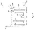
- Figure 1illustrates one suitable system and represents the INFINIT ® Vision System available from Alcon Laboratories, Inc., 6201 South Freeway, Q-148, Fort Worth, Texas 76134.
- Figure 2Aillustrates an exemplary control system 100 that can be used with this system.
- the control system 100is used to operate an ultrasound handpiece 112 and includes a control console 114, which has a control module or CPU 116, an aspiration, vacuum or peristaltic pump 118, a handpiece power supply 120, an irrigation flow or pressure sensor 122 and a valve 124.
- a control console 114which has a control module or CPU 116, an aspiration, vacuum or peristaltic pump 118, a handpiece power supply 120, an irrigation flow or pressure sensor 122 and a valve 124.
- Various ultrasound handpieces 112 and cutting tipscan be utilized including, but not limited to, handpieces and tips described in U.S. Pat. Nos.
- the CPU 116may be any suitable microprocessor, micro-controller, computer or digital logic controller.
- the pump 118may be a peristaltic, a diaphragm, a Venturi or other suitable pump.
- the power supply 120may be any suitable ultrasonic driver.
- the irrigation pressure sensor 122may be various commercially available sensors.
- the valve 124may be any suitable valve such as a solenoid-activated pinch valve.
- An infusion of an irrigation fluid, such as salinemay be provided by a saline source 126, which may be any commercially available irrigation solution provided in bottles or bags.
- the irrigation pressure sensor 122is connected to the handpiece 112 and the infusion fluid source 126 through irrigation lines 130, 132 and 134.
- the irrigation pressure sensor 122measures the flow or pressure of irrigation fluid from the source 126 to the handpiece 112 and supplies this information to the CPU 116 through the cable 136.
- the irrigation fluid flow datamay be used by the CPU 116 to control the operating parameters of the console 114 using software commands.
- the CPU 116may, through a cable 140, vary the output of the power supply 120 being sent to the handpiece 112 and the tip 113 though a power cable 142.
- the CPU 116may also use data supplied by the irrigation pressure sensor 122 to vary the operation of the pump 118 and/or valves through a cable 144.
- the pump 118aspirates fluid from the handpiece 112 through a line 146 and into a collection container 128 through line 148.
- the CPU 116may also use data supplied by the irrigation pressure sensor 122 and the applied output of power supply 120 to provide audible tones to the user. Additional details concerning such surgical systems can be found in U.S. Patent Nos. 6,179,808 (Boukhny, et al. ) and 6,261,283 (Morgan, et al. ).
- the control console 114can be programmed to control and manipulate pulses that are delivered to the handpiece 112 and, in turn, control the power of the pulses of the handpiece that is used during surgery.
- the pulsesare generated in packets or in on periods and off periods.
- the pulseshave a 50% duty cycle. Indeed, various on-times, off-times and duty cycles can be used for different applications.
- a maximum power level of 100%is the maximum attainable power (i.e., maximum stroke or displacement of the ultrasonic tip).
- 50% powerrefers to half of the maximum attainable power.
- Power levelsare represented as a percentage (%) of the maximum attainable power.
- Figures 3-21can be organized as micro-bursts or packets of pulses, as shown in Figures 2B and 2C.
- the packets or bursts of pulsesare provided to the ultrasound handpiece, which generates a generally corresponding output at the ultrasonic tip.
- one or both of the rise and decay components 310 and 312 of each pulse 300can be programmed separately from a natural rise and natural decay.
- rise and decay components 310 and 312can be programmed with linear and/or non-linear functions separately from natural rise and decay times that occur due to switching an amplifier on and off to generate pulses.
- pulsese.g., square and rectangular pulses
- such pulseshave natural rise and decay times, e.g., exponential rise and decay times, which are caused by a load or impedance.
- typical natural decay timescan be about 4 milliseconds (ms).
- Embodimentsin contrast, are directed to controlling linear rise and linear decay times separately from natural transitions that are caused by switching an amplifier on and off by setting or programming the rise and/or decay functions.
- Controlling the rise and decay components 310 and 312 and rise and decay times 312 and 322provides advantageously allows different pulse configurations to be generated for particular surgical applications and systems.
- pulses having programmed rise components 310 that gradually increase in powerallow the lens material to be positioned more accurately.
- Gradual power transitionsfor example, do not prematurely push the lens material away from the tip of the handpiece.
- known systems using pulses having sharp minimum to maximum transitionsmay inadvertently push lens material away from the tip too quickly, thus complicating the surgical procedure.
- pulses that include programmed rise componentscan improve the positioning and cutting of lens material and the effectiveness of surgical procedures.
- programming decay components and pulse timesallows less energy to be delivered to the eye, resulting in less heating of the tissue.
- the programmed rise and/or decay componentis programmed according to a linear function.
- each pulse 300is programmed with two linear components - a linear rise component 310 and a linear decay component 320.
- the linear rise component 310increases from a first amplitude to a second amplitude.
- An intermediate component 330extends between the linear components 310 and 320 at a second amplitude.
- the decay component 330decreases from the second amplitude to a third amplitude.
- the linear rise component 310has a linear rise time 312
- the linear decay component 320has a linear decay time 322
- the maximum amplitude component 330has a maximum amplitude or active or "on" time 332.
- Linear rise and linear decay times 312 and 322can vary depending on the maximum power level of a pulse since more time is typically required to reach higher power levels.
- the linear rise time 312can be programmed to be about 5 ms to about 500 ms. If a pulse must reach 100% power, the duration of the linear rise time 312 may be longer. However, if the pulse must reach less than 100% power, then the linear rise time 312 can be shorter, e.g. less than or about 5 ms. Linear rise time 312 durations may increase with increasing power levels and can be appropriately programmed using the control console 114. If necessary, the rate at which the linear component increases can be limited to protect power components, such as an amplifier.
- the linear decay time 322can be programmed to be about 5 ms to about 500 ms.
- the liner decay time 322is programmed using the control console 114 so that power decays linearly and about 70% of the power dissipates in about 2 ms, and about 98% of the power dissipates in about 4 ms.
- the linear decay time 322may be longer than, about the same as, or shorter than the linear rise time 312.
- Figure 3illustrates the decay time 322 being longer than the rise time 312.
- the linear decay time 322can be longer or slower than a natural decay time.
- the rise and decay ratesmay also be the same so that the pulse is symmetrical and has both programmed rise and decay components.
- the maximum amplitude or active or "on" time 332can vary with different applications.
- the maximum amplitude timecan be about 5 ms to about 500 ms.
- the intermediate component 330has a constant amplitude (at the second amplitude).
- the duration of the maximum amplitude timecan be less than 5 ms depending on, for example, required power and resulting heat considerations.
- the amplitudemay vary across the intermediate component 330, e.g., increase or decrease between the first and second components 310 and 320.
- the rise component 310begins at a non-zero level. In an alternative embodiment, the rise component 310 can begin at a zero level. The initial power level may depend on the particular surgical procedure and system configuration. Similarly, the decay component 320 can end at a zero or non-zero power level.
- Figure 3illustrates the first and third amplitudes being about the same. In alternative embodiments, they can be different. For example, the third amplitude at the end of the decay component 320 can be greater than the first amplitude.
- the programmed rise and/or decay componentcan be a non-linear component.
- a non-linear componentcan be programmed according to logarithmic, exponential and other non-linear functions.
- Figure 3illustrates linear rise and decay components.
- one or both of the rise and decay componentscan be programmed with a non-linear function.
- a pulse 400is programmed with linear rise and linear decay components 310 and 320 that meet at a maximum point 410 at a second amplitude rather than having an intermediate component 330, as shown in Figure 3.
- the programmed rise and decay times 312 and 322are equal.
- the linear rise and decay components 310 and 320meet at a midpoint.
- linear rise and decay times 312 and 322can be programmed to be about 5 ms to about 500 ms.
- the rise and decay timesmay not be equal, and the maximum point 410 may not be a midpoint.
- pulses having one or more linear and/or non-linear componentscan be combined with other pulses and pulse patterns.
- Figures 5-8illustrate pulses having programmed linear components, however, one or more programmed linear components can be replaced with a programmed non-linear component.
- Figure 5illustrates a sequence or combination 500 of pulses having a first rectangular pulse 510, a second rectangular pulse 520, a pulse 530 having a linear decay component, a pulse 540 having a linear rise component and a pulse 550 having linear rise and linear decay components, similar to the pulse shown in Figure 4.
- Figure 6illustrates a sequence or combination 600 of pulses according to another embodiment that includes a pulse 610 having linear rise and decay components and an intermediate component, similar to the pulse shown in Figure 3, a rectangular pulse 620, a rectangular pulse 630 having a longer duration than pulse 620, a pulse 640 having a linear decay component and a pulse 650 having a linear rise component.
- Figure 7illustrates yet a further embodiment of a sequence or combination 700 of pulses that includes a pulse 710 having a linear decay component, a multi-segment rectangular pulse 720 having decreasing amplitude, a pulse 730 having a linear decay component, a pulse 740 having a linear decay component and a 750 pulse having both linear rise and linear decay components, similar to the pulse shown in Figure 4, and another rectangular pulse 760.
- Figure 8illustrates a further alternative embodiment of a sequence or combination 800 of pulses having the same maximum amplitude and at least one pulse having a linear component.
- Figure 8illustrates a pulse 810 having a linear decay component, a multi-segment rectangular pulse 820 having decreasing amplitude, a pulse 810 having a linear decay component, a pulse 840 having a linear decay component, a pulse 850 having both linear rise and decay components, similar to the pulse shown in Figure 4, and a rectangular pulse 860.
- each pulse in a packet of pulsescan have an attribute that differentiates it from other pulses, e.g., based on different amplitude, duration, shape, number of programmed linear components and/or power.
- pulse combinationscan have pulses having different powers, amplitudes, shapes and durations.
- pulse combinationscan have different numbers of pulses, different numbers of rectangular and square pulses, different numbers of pulses having linear components, different numbers of pulses having one linear component, numbers of pulses having two linear components, and different numbers of pulses having two linear components and a constant amplitude component.
- the rectangular pulses and pulses having one or more linear componentcan be placed in different positions and sequences, e.g., and at the beginning or end of a pulse sequence, or somewhere in between.
- the order of rectangular (or other shaped pulses) and pulses having a linear componentcan be altered depending on the surgical application and the system used. Certain pulses may be grouped together or commingled with other types of pulses.
- rectangular pulses 510 and 520are grouped together and pulses 520, 530 and 540 having a linear component are grouped together.
- one or more non-rectangular pulsescan be between the rectangular pulses so that the rectangular pulses are commingled with different types pulses.
- one or more pulses that do not include a linear componentcan be placed between the pulses having a programmed linear component.
- pulses having a programmed linear componentare included in a pattern of pulses in which each pulse has sequentially decreasing power or increasing power.
- Figures 9-11illustrate pulse sequences in which each pulse has sequentially higher power
- Figures 12-14illustrate pulse sequences in which each pulse has sequentially decreasing power.
- an alternative embodimentincludes a sequence or combination 900 of pulses that includes pulses 910, 920, 930, 940 and 950, each of which is similar to the pulses shown in Figure 3.
- Each successive pulsehas a higher power (P1-P5) than a prior pulse.
- pulse 930has a power P3, which is greater than the power P2 of pulse 920.
- Figure 10illustrates an alternative embodiment in which a sequence or combination 1000 of pulses includes pulses 1010, 1020, 1030, 1040, and 1050, each of which is similar to the pulses shown in Figure 4. Each successive pulse has a higher power than a prior pulse.
- Figure 11illustrates yet a further embodiment in which a sequence or combination 1100 of pulses includes pulses of various shapes and sizes, including rectangular pulses and at least one pulse having a linear component. Each successive pulse has a higher power than a prior pulse.
- a sequence or group of pulses having an initial low power level and subsequent increasing power levelsmay be useful to effectively hold and control lens material at a tip of an ultrasound handpiece, while gradually increasing power to emulsify lens material.
- a sequence or combination 1200 of pulsesincludes pulses 1210, 1220, 1230, 1240 and 1250, each of which is similar to the pulse shown in Figure 3.
- Each pulseincludes a programmed linear rise component 310 and a programmed linear decay component 320.
- Each pulsehas reduced power relative to a prior pulse. For example, pulse P3 has less power than pulse P2, and pulse P4 has less power than pulse P3.
- a sequence or group of pulsesincludes pulses 1310, 1320, 1330, 1340 and 1350. Each pulse is similar to the pulse shown in Figure 4, and each pulse has reduced power relative to a prior pulse.
- Figure 14illustrates yet a further embodiment in which a sequence or combination 1400 of pulses 1410, 1420, 1430, 1440 and 1450 having reduced power over time.
- the combination 1400includes pulses having different shapes and sizes, including rectangular pulses and pulses having a linear component.
- alternative embodimentsare directed to transforming pulses between different pulse modes in response to a controller, such as a foot pedal or foot switch.
- pulsesare transferred between burst and pulse modes.
- Pulse patternsare shown relative to four foot pedal positions, which may or may not be defined by a detent or position indicator. Persons skilled in the art will appreciate that a foot pedal or switch can have other numbers of positions, and that the transitions described herein can be performed by pressing and releasing the foot pedal.
- burst modeprovides a series of periodic, fixed width, constant amplitude pulses 1500 of ultrasonic power, each of which is followed by an "off" time 1510.
- the off time 1510 between pulses 1500is controlled by the surgeon's input by moving or pressing the foot pedal.
- each pulse 1500has a fixed "on” time 1520, and a variable “off” time 1510, and the "off” time 1510 is adjusted based on the user's manipulation of the foot pedal.
- Burst mode pulsescan have active times of about 5 ms to about 500 ms.
- burst mode pulsesmay be "fixed burst" mode pulses as shown in Figure 15 or, alternatively, be “linear burst” mode pulses as shown in Figure 16.
- fixed burst modepressing the foot pedal decreases the off-time 1510, while the amplitude of the pulses remains constant.
- linear burst modepressing the foot pedal decreases the off-time 1500 and, in addition, adjusts the amplitude. In the illustrated embodiment, pressing the foot pedal increases the amplitude.
- the power "Off" time 1510can be adjusted, and the amplitude of pulses may or may not be adjusted.
- Figures 15 and 16illustrate a foot pedal in four positions.
- the off time 1510decreases when the foot pedal is initially at Position 1 and pressed further to Position 2.
- the number of fixed width, constant amplitude pulses 1500increases as the foot pedal is pressed.
- the off time 1510eventually reaches a pre-determined off time 1520, e.g., the on time 1520 or another suitable time. Pressing the foot pedal further from position 3 to position 4 reduces the off time 1510 to zero, i.e., a 100% on-time 1520 (continuous mode).
- the pulsesare linear burst mode pulses, and the amplitude of the pulses also increases as the foot pedal is moved among different positions.
- the amplitude of fixed-width pulses 1700changes according to the position of the foot pedal. In the illustrated embodiment, the amplitude increases by pressing the foot pedal.
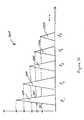
- FIG. 18illustrates transitioning from burst mode to pulse mode.
- the foot pedalis pressed from Position 1 to Position 2 to decrease the off time 1510.
- the off-timedecreases further when the foot pedal is pressed from Position 2 to Position 3.
- the number of fixed width, constant amplitude pulses in a period of timeincreases as the foot pedal is pressed further.
- the off time 1510eventually reaches a pre-determined value, such as the on time 1520 or another suitable value.
- the pre-determined valueis equal to the on-time 1520.
- the pulse amplitudeis then adjusted after the off time 1510 is the same as the on time 1520 (or another suitable value), thereby increasing energy generated by the handpiece, and transforming pulses from burst mode to pulse mode pulses.
- pulsesare transformed from pulse mode to burst mode pulses. If the system is initially in pulse mode and the foot pedal is pressed to position 4, releasing the foot pedal initially decreases the amplitude of the pulses. After the amplitude reaches a pre-determined amplitude, releasing the foot pedal further results in adjusting the burst mode and increasing the power "Off" time 1510, thereby providing fewer fixed width pulses 1500 in a given time and less power to the ultrasonic tip 113, in order to cool the tip 113.
- a surgeoncan advantageously switch between burst mode and pulse mode pulses by manipulating a single controller, e.g., by pressing and releasing the foot pedal.
- This arrangementis particularly beneficial since these transformations can be achieved without the interruptions and adjustments that are otherwise associated with changing to different pulse modes, e.g., adjusting parameters on a display screen or interface.
- embodimentsadvantageously allow continuous pulse transitions by pressing and releasing the foot pedal as part of a natural and continuous motion of the surgeon's foot, thereby simplifying the configuration and operation of surgical equipment and simplifying surgical procedures.
- the amount of power of each pulsecan be gradually increased by utilizing a multi-step or multi-segment pulse 2000.
- a multi-segment pulsecan have two, three, four and other numbers of segments.
- the two-segment pulse shown in Figure 20is provided for purposes of illustration, not limitation.
- a first step 2010has less power than a subsequent step 2020.
- a first pulse segment 2010is at a first amplitude for a pre-determined time, followed by a second pulse segment 2020 at a second amplitude for a predetermined time.
- Configuring a multi-segment pulse to provide a gradual transition from low power to higher powerprovides the ability to hold and emulsify lens material more accurately in contrast to abrupt transitions from low to maximum power levels such as in a typical square, which can inadvertently move lens material away from the tip during cutting of the lens material
- a multi-segment pulse 2100may have more than two segments of increasing amplitude.
- a pulsehas three pulse segments 2110, 2120 and 2130. Other pulses may have four, five and other numbers of pulse segments as needed.
- the different pulses and pulse patterns described aboveare pulses of ultrasonic energy that can be delivered in packets to transducer elements of the handpiece.
- ultrasonic energyis delivered to piezoelectric elements as intermittent packets of pulses that are separated by an off period.
- the pulses patterns according to alternative embodiments of the invention described aboveare delivered to piezoelectric elements of an ultrasound handpiece during these "on" times and within these packets.
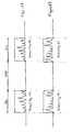
- Figure 23illustrates packets of pulses of ultrasonic energy having sequentially increasing power, as shown in Figure 10.
- Figure 24illustrates packets of pulses of ultrasonic energy having sequentially decreasing power, as shown in Figure 13.
- a packetmay have one or multiple groups of pulses, and that a packet may end at the end of a group of pulses or in the middle of a group of pulses.
- Figures 22 and 23illustrate a packet ending with the second pulse in a group of pulses. The packet may also end with the last pulse in the group of pulses.
- Figures 22 and 23are provided for purposes of illustration, not limitation. Persons skilled in the art will also appreciate that the embodiments of pulses described in this specification are not required to be framed or organized in packets in order to control the ultrasound handpiece.
Landscapes
- Health & Medical Sciences (AREA)
- Engineering & Computer Science (AREA)
- Ophthalmology & Optometry (AREA)
- Life Sciences & Earth Sciences (AREA)
- General Health & Medical Sciences (AREA)
- Biomedical Technology (AREA)
- Heart & Thoracic Surgery (AREA)
- Vascular Medicine (AREA)
- Nuclear Medicine, Radiotherapy & Molecular Imaging (AREA)
- Animal Behavior & Ethology (AREA)
- Surgery (AREA)
- Public Health (AREA)
- Veterinary Medicine (AREA)
- Mechanical Engineering (AREA)
- Surgical Instruments (AREA)
- Ultra Sonic Daignosis Equipment (AREA)
- Electrotherapy Devices (AREA)
- Laser Surgery Devices (AREA)
- Processing Of Color Television Signals (AREA)
Abstract
Description
- The present invention relates generally to the field of ophthalmic surgery and, more particularly, to a method of manipulating the shapes, sequences and durations of pulses of ultrasonic energy generated by an ultrasound handpiece of a phacoemulsification surgical system.
- The human eye functions to provide vision by transmitting light through a clear outer portion called the cornea, and focusing the image by way of a lens onto a retina. The quality of the focused image depends on many factors including the size and shape of the eye, and the transparency of the cornea and lens. When age or disease causes the lens to become less transparent, vision deteriorates because of the diminished light that can be transmitted to the retina. This deficiency is medically known as a cataract. An accepted treatment for cataracts is to surgically remove the cataract and replace the lens with an artificial intraocular lens (IOL). In the United States, the majority of cataractous lenses are removed using a surgical technique called phacoemulsification. During this procedure, a thin cutting tip or needle is inserted into the diseased lens and vibrated ultrasonically. The vibrating cutting tip liquefies or emulsifies the lens, which is aspirated out of the eye. The diseased lens, once removed, is replaced by an IOL.
- A typical ultrasonic surgical device suitable for an ophthalmic procedure includes an ultrasonically driven handpiece, an attached cutting tip, an irrigating sleeve or other suitable irrigation device, and an electronic control console. The handpiece assembly is attached to the control console by an electric cable or connector and flexible tubings. A surgeon controls the amount of ultrasonic energy that is delivered to the cutting tip of the handpiece and applied to tissue by pressing a foot pedal to request power up to the maximum amount of power set on the console. Tubings supply irrigation fluid to and draw aspiration fluid from the eye through the handpiece assembly.
- The operative part of the handpiece is a centrally located, hollow resonating bar or horn that is attached to piezoelectric crystals. The crystals are controlled by the console and supply ultrasonic vibrations that drive both the horn and the attached cutting tip during phacoemulsification. The crystal/horn assembly is suspended within the hollow body or shell of the handpiece by flexible mountings. The handpiece body terminates in a reduced diameter portion or nosecone at the body's distal end. The nosecone is externally threaded to accept the irrigation sleeve. Likewise, the horn bore is internally threaded at its distal end to receive the external threads of the cutting tip. The irrigation sleeve also has an internally threaded bore that is screwed onto the external threads of the nosecone. The cutting tip is adjusted so that the tip projects only a predetermined amount past the open end of the irrigating sleeve.
- In use, the ends of the cutting tip and the irrigating sleeve are inserted into a small incision in the cornea, sclera, or other location. One known cutting tip is ultrasonically vibrated along its longitudinal axis within the irrigating sleeve by the crystal-driven ultrasonic horn, thereby emulsifying the selected tissue in situ. The hollow bore of the cutting tip communicates with the bore in the horn that in turn communicates with the aspiration line from the handpiece to the console. Other suitable cutting tips include piezoelectric elements that produce both longitudinal and torsional oscillations. One example of such a cutting tip is described in
U.S. Patent No. 6,402,769 (Boukhny ). - A reduced pressure or vacuum source in the console draws or aspirates emulsified tissue from the eye through the open end of the cutting tip, the cutting tip and horn bores and the aspiration line, and into a collection device. The aspiration of emulsified tissue is aided by a saline solution or other irrigant that is injected into the surgical site through the small annular gap between the inside surface of the irrigating sleeve and the cutting tip.
- One known technique is to make the incision into the anterior chamber of the eye as small as possible in order to reduce the risk of induced astigmatism. These small incisions result in very tight wounds that squeeze the irrigating sleeve tightly against the vibrating tip. Friction between the irrigating sleeve and the vibrating tip generates heat. The risk of the tip overheating and burning tissue is reduced by the cooling effect of the aspirated fluid flowing inside the tip.
- Some known surgical systems use "pulse mode" in which the amplitude of fixed-width pulses can be varied using a controller, such as a foot pedal. Other known surgical systems utilize "burst mode" in which each pulse of a series of periodic, fixed width, constant amplitude pulses is followed by an "off" time. The off time can be varied using a controller. Other known systems use pulses having an initial maximum power level followed by a lower power level. For example, Publication
No. PCT/US2004/007318 describes pulses that rise from zero to an initial, maximum power level, and then subsequently decrease to lower levels. - While known surgical systems have been used effectively, they can be improved by allowing greater control over pulses for use with various surgical devices and applications. For example, known systems that use square or rectangular pulses typically have power levels that increase very quickly to a maximum power level. Sharp pulse transitions can reduce the ability to hold and emulsify lens material. More specifically, when lens material is held at a tip of an ultrasound hand piece by vacuum, the very fast (almost immediate) ramping of a pulse to a maximum power level can displace or push the lens material away from the tip too quickly. This, in turn, complicates cutting of the lens material. In other words, rapid power transitions can create an imbalance between vacuum at the ultrasonic tip that holds or positions the lens material and the ability to emulsify lens material.
- Other known systems operate at high power levels when less power or no power would suffice. For example, with rectangular pulses, an initial high power level may be needed to provide power to emulsify lens material. However, after the material is pushed away or emulsified, additional power may not be needed. Rectangular pulses that apply the same amount of power after movement or emulsification of lens material can result in excessive heat being applied to tissue, which can harm the patient.
- Further, pulse patterns that are used by some known surgical systems do not adequately reduce cavitation effects. Cavitation is the formation of small bubbles resulting from the back and forth movement of an ultrasonic tip. This movement causes pockets of low and high pressure. As the ultrasonic tip moves backwards, it vaporizes liquid due to a low local pressure and generates bubbles. The bubbles are compressed as the tip moves forwards and implode. Imploding bubbles can create unwanted heat and forces and complicate surgical procedures and present dangers to the patient.
- Therefore, a need continues to exist for methods that allow pulse shapes and durations to be manipulated for different phacoemulsification applications and procedures.
- The present invention provides methods of generating ultrasonic energy for use with an ophthalmic surgical device, in accordance with claims which follow. In accordance with one embodiment of the invention, a method of generating ultrasonic energy for use with an ophthalmic surgical device includes generating pulses having an on-time, a first off-time, and a first amplitude. The first off-time is greater than the on-time. The method includes reducing the first off-time of the pulses and increasing the amplitude of the pulses from the first amplitude to a second amplitude when the first off-time is reduced to a pre-determined second off-time.
- The first off-time can be reduced in response to a controller, such as a foot pedal. The first off-time can be reduced until the foot pedal reaches a pre-determined position corresponding to a certain off-time of the pulses, after which the off-time remains constant. The amplitude of the pulses is increased after the pre-determined second off-time is about the same as the on-time in response to the foot pedal. The off-time and the amplitude can be adjusted with continuous movement of a single controller.
- In accordance with another embodiment of the invention, a method of generating ultrasonic energy for use with an ophthalmic surgical device includes generating burst mode pulses and transforming burst mode pulses into pulse mode pulses in response to a controller.
- In accordance with a further embodiment of the invention, a method of generating ultrasonic energy for use with an ophthalmic surgical device includes generating pulse mode pulses and transforming pulse mode pulses into burst mode pulses in response to a controller.
- Transforming between burst and pulse modes can be performed in response to movement of the foot pedal and begins after the foot pedal reaches a pre-determined position. Burst mode pulses are generated by generating pulses having an on-time, a first off-time and a first amplitude. Burst mode pulses are transformed into pulse mode pulses by reducing the first off-time of the pulses to a second off-time in response to the controller. When the second off-time reaches a pre-determined value, the amplitude of the pulses is increased from the first amplitude to a second amplitude in response to the controller. The pre-determined value can be the same as the on-time or another desired value. The on-time remains constant during the transforming step.
- Referring now to the drawings, in which like reference numbers represent corresponding parts throughout and in which:
- Figure 1 illustrates an exemplary phacoemulsification surgical system that may be used with various embodiments;
- Figure 2A is block diagram showing components of an exemplary phacoemulsification surgical system;
- Figures 2B and 2C illustrate pulses for use with a phacoemulsification surgical system;
- Figure 3 illustrates pulses having linear rise and linear decay components and a constant maximum amplitude component according to one embodiment;
- Figure 4 illustrates pulses having linear rise and linear decay components that meet at a maximum point according to a further embodiment;
- Figure 5 illustrates a combination of pulses having a rectangular pulse and a pulse having a linear component according to another embodiment;
- Figure 6 illustrates a combination of pulses having a rectangular pulse and a pulse having a linear component according to further embodiment;
- Figure 7 illustrates a combination of pulses having a rectangular pulse and a pulse having a linear component according to yet a further embodiment;
- Figure 8 illustrates a combination of pulses having a rectangular pulse and a pulse having a linear component at the same amplitude according to one embodiment;
- Figure 9 illustrates pulses having linear rise and decay components, a constant amplitude component that has sequentially increasing power according to one embodiment;
- Figure 10 illustrates pulses having linear rise and decay components that meet at a maximum point and that have sequentially increasing power according to a further embodiment;
- Figure 11 illustrates a combination of rectangular pulses and pulses having a linear component having sequentially increasing power according to one embodiment;
- Figure 12 illustrates pulses having linear rise and decay components, a constant amplitude component and sequentially decreasing power according to one embodiment;
- Figure 13 illustrates pulses having linear rise and linear decay components that meet at a maximum point and having sequentially decreasing power according to a further embodiment;
- Figure 14 illustrates a combination of rectangular pulses and pulses having a linear component and that have sequentially decreasing power according to another embodiment;
- Figure 15 illustrates known fixed burst mode pulses;
- Figure 16 illustrates known linear burst mode pulses;
- Figure 17 illustrates known pulse mode pulses;
- Figure 18 illustrates continuous transformation of burst mode pulses to pulse mode pulses in response to a controller according to one embodiment;
- Figure 19 illustrates continuous transformation of pulse mode pulses to burst mode pulses in response to a controller according to another embodiment;
- Figure 20 illustrates multi-segment rectangular pulses having two pulse segments with increasing amplitude according to yet another embodiment;
- Figure 21 illustrates a multi-segment rectangular pulse according to an alternative embodiment having three pulse segments with increasing amplitude;
- Figure 22 illustrates packets of pulses of ultrasonic energy shown in Figure 10; and
- Figure 23 illustrates packets of pulses of ultrasonic energy shown in Figure 13.
- This specification describes embodiments of methods of manipulating pulses of ultrasonic energy to control a surgical system for use in, for example, phacoemulsification surgery. Embodiments can be implemented on commercially available surgical systems or consoles through appropriate hardware and software controls. Figures 1 and 2 illustrate exemplary surgical systems.
- Figure 1 illustrates one suitable system and represents the INFINIT® Vision System available from Alcon Laboratories, Inc., 6201 South Freeway, Q-148, Fort Worth, Texas 76134. Figure 2A illustrates an
exemplary control system 100 that can be used with this system. - The
control system 100 is used to operate an ultrasound handpiece 112 and includes a control console 114, which has a control module or CPU 116, an aspiration, vacuum or peristaltic pump 118, a handpiece power supply 120, an irrigation flow orpressure sensor 122 and avalve 124. Various ultrasound handpieces 112 and cutting tips can be utilized including, but not limited to, handpieces and tips described inU.S. Pat. Nos. 3,589,363 ;4,223,676 ;4,246,902 ;4,493,694 ;4,515,583 ;4,589,415 ;4,609,368 ;4,869,715 ;4,922,902 ;4,989,583 ;5,154,694 and5,359,996 . The CPU 116 may be any suitable microprocessor, micro-controller, computer or digital logic controller. The pump 118 may be a peristaltic, a diaphragm, a Venturi or other suitable pump. The power supply 120 may be any suitable ultrasonic driver. Theirrigation pressure sensor 122 may be various commercially available sensors. Thevalve 124 may be any suitable valve such as a solenoid-activated pinch valve. An infusion of an irrigation fluid, such as saline, may be provided by asaline source 126, which may be any commercially available irrigation solution provided in bottles or bags. - In use, the
irrigation pressure sensor 122 is connected to the handpiece 112 and theinfusion fluid source 126 throughirrigation lines 130, 132 and 134. Theirrigation pressure sensor 122 measures the flow or pressure of irrigation fluid from thesource 126 to the handpiece 112 and supplies this information to the CPU 116 through the cable 136. The irrigation fluid flow data may be used by the CPU 116 to control the operating parameters of the console 114 using software commands. For example, the CPU 116 may, through a cable 140, vary the output of the power supply 120 being sent to the handpiece 112 and thetip 113 though apower cable 142. The CPU 116 may also use data supplied by theirrigation pressure sensor 122 to vary the operation of the pump 118 and/or valves through a cable 144. The pump 118 aspirates fluid from the handpiece 112 through aline 146 and into a collection container 128 throughline 148. The CPU 116 may also use data supplied by theirrigation pressure sensor 122 and the applied output of power supply 120 to provide audible tones to the user. Additional details concerning such surgical systems can be found inU.S. Patent Nos. 6,179,808 (Boukhny, et al. ) and6,261,283 (Morgan, et al. ). - The control console 114 can be programmed to control and manipulate pulses that are delivered to the handpiece 112 and, in turn, control the power of the pulses of the handpiece that is used during surgery. Referring to Figures 2B and 2C, the pulses are generated in packets or in on periods and off periods. In the illustrated example, the pulses have a 50% duty cycle. Indeed, various on-times, off-times and duty cycles can be used for different applications.
- The following description assumes that a maximum power level of 100% is the maximum attainable power (i.e., maximum stroke or displacement of the ultrasonic tip). In other words, 50% power refers to half of the maximum attainable power. Power levels are represented as a percentage (%) of the maximum attainable power. Embodiments of pulse manipulation that can be used with the exemplary phacoemulsification surgical system described above are illustrated in Figures 3-21, which can be organized as micro-bursts or packets of pulses, as shown in Figures 2B and 2C. The packets or bursts of pulses are provided to the ultrasound handpiece, which generates a generally corresponding output at the ultrasonic tip.
- Referring to Figure 3, according to one embodiment, one or both of the rise and
decay components pulse 300 can be programmed separately from a natural rise and natural decay. For example rise anddecay components - Controlling the rise and
decay components decay times rise components 310 that gradually increase in power allow the lens material to be positioned more accurately. Gradual power transitions, for example, do not prematurely push the lens material away from the tip of the handpiece. In contrast, known systems using pulses having sharp minimum to maximum transitions may inadvertently push lens material away from the tip too quickly, thus complicating the surgical procedure. Accordingly, pulses that include programmed rise components can improve the positioning and cutting of lens material and the effectiveness of surgical procedures. Further, programming decay components and pulse times allows less energy to be delivered to the eye, resulting in less heating of the tissue. - According to one embodiment, the programmed rise and/or decay component is programmed according to a linear function. In the embodiment illustrated in Figure 3, each
pulse 300 is programmed with two linear components - alinear rise component 310 and alinear decay component 320. Thelinear rise component 310 increases from a first amplitude to a second amplitude. Anintermediate component 330 extends between thelinear components decay component 330 decreases from the second amplitude to a third amplitude. - The
linear rise component 310 has alinear rise time 312, thelinear decay component 320 has alinear decay time 322, and themaximum amplitude component 330 has a maximum amplitude or active or "on"time 332. Linear rise andlinear decay times - In one embodiment, the
linear rise time 312 can be programmed to be about 5 ms to about 500 ms. If a pulse must reach 100% power, the duration of thelinear rise time 312 may be longer. However, if the pulse must reach less than 100% power, then thelinear rise time 312 can be shorter, e.g. less than or about 5 ms.Linear rise time 312 durations may increase with increasing power levels and can be appropriately programmed using the control console 114. If necessary, the rate at which the linear component increases can be limited to protect power components, such as an amplifier. - According to one embodiment, the
linear decay time 322 can be programmed to be about 5 ms to about 500 ms. In one embodiment, theliner decay time 322 is programmed using the control console 114 so that power decays linearly and about 70% of the power dissipates in about 2 ms, and about 98% of the power dissipates in about 4 ms. Thelinear decay time 322 may be longer than, about the same as, or shorter than thelinear rise time 312. For example, Figure 3 illustrates thedecay time 322 being longer than therise time 312. Thelinear decay time 322 can be longer or slower than a natural decay time. The rise and decay rates may also be the same so that the pulse is symmetrical and has both programmed rise and decay components. - The maximum amplitude or active or "on"
time 332 can vary with different applications. The maximum amplitude time can be about 5 ms to about 500 ms. In the illustrated embodiment, theintermediate component 330 has a constant amplitude (at the second amplitude). In an alternative embodiment, the duration of the maximum amplitude time can be less than 5 ms depending on, for example, required power and resulting heat considerations. In further alternative embodiments, the amplitude may vary across theintermediate component 330, e.g., increase or decrease between the first andsecond components - In the illustrated embodiment, the
rise component 310 begins at a non-zero level. In an alternative embodiment, therise component 310 can begin at a zero level. The initial power level may depend on the particular surgical procedure and system configuration. Similarly, thedecay component 320 can end at a zero or non-zero power level. Figure 3 illustrates the first and third amplitudes being about the same. In alternative embodiments, they can be different. For example, the third amplitude at the end of thedecay component 320 can be greater than the first amplitude. - In an alternative embodiment, the programmed rise and/or decay component can be a non-linear component. A non-linear component can be programmed according to logarithmic, exponential and other non-linear functions. For purposes of explanation, not limitation, Figure 3 illustrates linear rise and decay components. However, one or both of the rise and decay components can be programmed with a non-linear function.
- Referring to Figure 4, according to an alternative embodiment, a
pulse 400 is programmed with linear rise andlinear decay components maximum point 410 at a second amplitude rather than having anintermediate component 330, as shown in Figure 3. In the illustrated embodiment, the programmed rise anddecay times decay components decay times maximum point 410 may not be a midpoint. - Referring to Figures 5-8, in alternative embodiments, pulses having one or more linear and/or non-linear components can be combined with other pulses and pulse patterns. For purposes of explanation, not limitation, Figures 5-8 illustrate pulses having programmed linear components, however, one or more programmed linear components can be replaced with a programmed non-linear component.
- Figure 5 illustrates a sequence or
combination 500 of pulses having a firstrectangular pulse 510, a secondrectangular pulse 520, a pulse 530 having a linear decay component, apulse 540 having a linear rise component and apulse 550 having linear rise and linear decay components, similar to the pulse shown in Figure 4. - Figure 6 illustrates a sequence or
combination 600 of pulses according to another embodiment that includes apulse 610 having linear rise and decay components and an intermediate component, similar to the pulse shown in Figure 3, a rectangular pulse 620, a rectangular pulse 630 having a longer duration than pulse 620, a pulse 640 having a linear decay component and apulse 650 having a linear rise component. - Figure 7 illustrates yet a further embodiment of a sequence or
combination 700 of pulses that includes apulse 710 having a linear decay component, a multi-segmentrectangular pulse 720 having decreasing amplitude, apulse 730 having a linear decay component, apulse 740 having a linear decay component and a 750 pulse having both linear rise and linear decay components, similar to the pulse shown in Figure 4, and anotherrectangular pulse 760. - Figure 8 illustrates a further alternative embodiment of a sequence or
combination 800 of pulses having the same maximum amplitude and at least one pulse having a linear component. In particular, Figure 8 illustrates apulse 810 having a linear decay component, a multi-segment rectangular pulse 820 having decreasing amplitude, apulse 810 having a linear decay component, apulse 840 having a linear decay component, apulse 850 having both linear rise and decay components, similar to the pulse shown in Figure 4, and arectangular pulse 860. - As illustrated in Figures 5-8, each pulse in a packet of pulses can have an attribute that differentiates it from other pulses, e.g., based on different amplitude, duration, shape, number of programmed linear components and/or power. For example, pulse combinations can have pulses having different powers, amplitudes, shapes and durations. Further, pulse combinations can have different numbers of pulses, different numbers of rectangular and square pulses, different numbers of pulses having linear components, different numbers of pulses having one linear component, numbers of pulses having two linear components, and different numbers of pulses having two linear components and a constant amplitude component. Thus, embodiments surgeons to customize pulses to suite particular surgical procedures and phacoemulsification systems.
- As shown in Figure 5-8, the rectangular pulses and pulses having one or more linear component, can be placed in different positions and sequences, e.g., and at the beginning or end of a pulse sequence, or somewhere in between. The order of rectangular (or other shaped pulses) and pulses having a linear component can be altered depending on the surgical application and the system used. Certain pulses may be grouped together or commingled with other types of pulses.
- For example, referring to Figure 5,
rectangular pulses pulses - Referring to Figures 9-14, in alternative embodiments, pulses having a programmed linear component are included in a pattern of pulses in which each pulse has sequentially decreasing power or increasing power. Figures 9-11 illustrate pulse sequences in which each pulse has sequentially higher power, and Figures 12-14 illustrate pulse sequences in which each pulse has sequentially decreasing power.
- Referring to Figure 9, an alternative embodiment includes a sequence or
combination 900 of pulses that includespulses pulse 930 has a power P3, which is greater than the power P2 ofpulse 920. - Figure 10 illustrates an alternative embodiment in which a sequence or
combination 1000 of pulses includespulses - Figure 11 illustrates yet a further embodiment in which a sequence or
combination 1100 of pulses includes pulses of various shapes and sizes, including rectangular pulses and at least one pulse having a linear component. Each successive pulse has a higher power than a prior pulse. A sequence or group of pulses having an initial low power level and subsequent increasing power levels may be useful to effectively hold and control lens material at a tip of an ultrasound handpiece, while gradually increasing power to emulsify lens material. - Referring to Figure 12, according to another embodiment, a sequence or
combination 1200 of pulses includespulses linear rise component 310 and a programmedlinear decay component 320. Each pulse has reduced power relative to a prior pulse. For example, pulse P3 has less power than pulse P2, and pulse P4 has less power than pulse P3. - In an alternative embodiment, referring to Figure 13, a sequence or group of pulses includes
pulses combination 1400 ofpulses combination 1400 includes pulses having different shapes and sizes, including rectangular pulses and pulses having a linear component. - Referring to Figures 15-19, alternative embodiments are directed to transforming pulses between different pulse modes in response to a controller, such as a foot pedal or foot switch. According to one embodiment, pulses are transferred between burst and pulse modes. Pulse patterns are shown relative to four foot pedal positions, which may or may not be defined by a detent or position indicator. Persons skilled in the art will appreciate that a foot pedal or switch can have other numbers of positions, and that the transitions described herein can be performed by pressing and releasing the foot pedal.
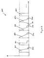
- Referring to Figure 15, "burst" mode provides a series of periodic, fixed width,
constant amplitude pulses 1500 of ultrasonic power, each of which is followed by an "off"time 1510. Theoff time 1510 betweenpulses 1500 is controlled by the surgeon's input by moving or pressing the foot pedal. In other words, in burst mode, eachpulse 1500 has a fixed "on"time 1520, and a variable "off"time 1510, and the "off"time 1510 is adjusted based on the user's manipulation of the foot pedal. Burst mode pulses can have active times of about 5 ms to about 500 ms. The spacing between bursts or the "off-time" can be about 0 ms (when the foot pedal is fully depressed and power is continuous) to about 2.5 seconds. The off-time can depend on the application and system, for example, the desired amount of cooling or heat dissipation that may be required. Burst mode pulses may be "fixed burst" mode pulses as shown in Figure 15 or, alternatively, be "linear burst" mode pulses as shown in Figure 16. In fixed burst mode, pressing the foot pedal decreases the off-time 1510, while the amplitude of the pulses remains constant. In linear burst mode, pressing the foot pedal decreases the off-time 1500 and, in addition, adjusts the amplitude. In the illustrated embodiment, pressing the foot pedal increases the amplitude. Thus, in both fixed and linear burst modes, the power "Off"time 1510 can be adjusted, and the amplitude of pulses may or may not be adjusted. - More particularly, Figures 15 and 16 illustrate a foot pedal in four positions. The
off time 1510 decreases when the foot pedal is initially atPosition 1 and pressed further toPosition 2. The number of fixed width,constant amplitude pulses 1500 increases as the foot pedal is pressed. As the foot pedal is pressed fromPosition 2 toPosition 3, theoff time 1510 eventually reaches a pre-determined offtime 1520, e.g., the ontime 1520 or another suitable time. Pressing the foot pedal further fromposition 3 toposition 4 reduces theoff time 1510 to zero, i.e., a 100% on-time 1520 (continuous mode). A similar process is illustrated in Figure 16, except that the pulses are linear burst mode pulses, and the amplitude of the pulses also increases as the foot pedal is moved among different positions. - Referring to Figure 17, in "pulse" mode, the amplitude of fixed-
width pulses 1700 changes according to the position of the foot pedal. In the illustrated embodiment, the amplitude increases by pressing the foot pedal. - Referring to Figures 18 and 19, alternative embodiments are directed to transforming pulses between burst and pulse modes in response to movement of the foot pedal. Figure 18 illustrates transitioning from burst mode to pulse mode. The foot pedal is pressed from
Position 1 toPosition 2 to decrease theoff time 1510. The off-time decreases further when the foot pedal is pressed fromPosition 2 toPosition 3. The number of fixed width, constant amplitude pulses in a period of time increases as the foot pedal is pressed further. As the foot pedal is pressed further, theoff time 1510 eventually reaches a pre-determined value, such as the ontime 1520 or another suitable value. In the illustrated embodiment, the pre-determined value is equal to the on-time 1520. The pulse amplitude is then adjusted after theoff time 1510 is the same as the on time 1520 (or another suitable value), thereby increasing energy generated by the handpiece, and transforming pulses from burst mode to pulse mode pulses. - Referring to Figure 19, in an alternative embodiment, pulses are transformed from pulse mode to burst mode pulses. If the system is initially in pulse mode and the foot pedal is pressed to
position 4, releasing the foot pedal initially decreases the amplitude of the pulses. After the amplitude reaches a pre-determined amplitude, releasing the foot pedal further results in adjusting the burst mode and increasing the power "Off"time 1510, thereby providing fewer fixedwidth pulses 1500 in a given time and less power to theultrasonic tip 113, in order to cool thetip 113. - As shown in Figures 18 and 19, a surgeon can advantageously switch between burst mode and pulse mode pulses by manipulating a single controller, e.g., by pressing and releasing the foot pedal. This arrangement is particularly beneficial since these transformations can be achieved without the interruptions and adjustments that are otherwise associated with changing to different pulse modes, e.g., adjusting parameters on a display screen or interface. Instead, embodiments advantageously allow continuous pulse transitions by pressing and releasing the foot pedal as part of a natural and continuous motion of the surgeon's foot, thereby simplifying the configuration and operation of surgical equipment and simplifying surgical procedures.
- Referring to Figure 20, in a further alternative embodiment, the amount of power of each pulse can be gradually increased by utilizing a multi-step or
multi-segment pulse 2000. Persons skilled in the art will appreciate that a multi-segment pulse can have two, three, four and other numbers of segments. Thus, the two-segment pulse shown in Figure 20 is provided for purposes of illustration, not limitation. - In the illustrated embodiment, a
first step 2010 has less power than asubsequent step 2020. For example, as shown in Figure 20, afirst pulse segment 2010 is at a first amplitude for a pre-determined time, followed by asecond pulse segment 2020 at a second amplitude for a predetermined time. Configuring a multi-segment pulse to provide a gradual transition from low power to higher power provides the ability to hold and emulsify lens material more accurately in contrast to abrupt transitions from low to maximum power levels such as in a typical square, which can inadvertently move lens material away from the tip during cutting of the lens material Referring to Figure 21, in alternative embodiments, amulti-segment pulse 2100 may have more than two segments of increasing amplitude. In the illustrated embodiment, a pulse has threepulse segments - The different pulses and pulse patterns described above are pulses of ultrasonic energy that can be delivered in packets to transducer elements of the handpiece. For example, as shown in Figures 2B and 2C, ultrasonic energy is delivered to piezoelectric elements as intermittent packets of pulses that are separated by an off period. The pulses patterns according to alternative embodiments of the invention described above are delivered to piezoelectric elements of an ultrasound handpiece during these "on" times and within these packets.
- For example, Figure 23 illustrates packets of pulses of ultrasonic energy having sequentially increasing power, as shown in Figure 10. As a further example, Figure 24 illustrates packets of pulses of ultrasonic energy having sequentially decreasing power, as shown in Figure 13. Persons skilled in the art will appreciate that a packet may have one or multiple groups of pulses, and that a packet may end at the end of a group of pulses or in the middle of a group of pulses. For example, Figures 22 and 23 illustrate a packet ending with the second pulse in a group of pulses. The packet may also end with the last pulse in the group of pulses. Accordingly, Figures 22 and 23 are provided for purposes of illustration, not limitation. Persons skilled in the art will also appreciate that the embodiments of pulses described in this specification are not required to be framed or organized in packets in order to control the ultrasound handpiece.
- Although references have been made in the foregoing description to various embodiments, persons of skilled in the art will recognize that insubstantial modifications, alterations, and substitutions can be made to the described embodiments without departing from the scope of embodiments.
Claims (25)
- A method of generating ultrasonic energy for use with an ophthalmic surgical device (112), the method comprising:generating pulses (1500,1700) having an on-time (1520), a first off-time (1510), and a first amplitude, the first off-time being greater than the on-time;reducing the first off-time of the pulses; andincreasing the amplitude of the pulses from the first amplitude to a second amplitude when the first off-time is reduced to a pre-determined second off-time.
- The method of claim 1, wherein reducing the first off-time (1510) comprises reducing the first off-time in response to a controller.
- The method of claim 2, wherein the controller is a foot pedal and reducing the first off-time (1510) comprises reducing the first off-time in response to movement of the foot pedal.
- The method of claim 3, wherein reducing the first off-time (1510) comprises reducing the first off-time until the foot pedal reaches a pre-determined position, after which the off-time remains constant.
- The method of claim 1, wherein increasing the amplitude of the pulses from the first amplitude to the second amplitude begins after the pre-determined second off-time is about the same as the on-time (1520).
- The method of claim 1, wherein increasing the amplitude comprises increasing the amplitude from the first amplitude to the second amplitude in response to a controller.
- The method of claim 6, wherein the controller is a foot pedal and the first amplitude is increased in response to movement of the foot pedal.
- The method of claim 7, wherein increasing the amplitude of the pulses (1500,1700) from the first amplitude to the second amplitude begins after the foot pedal is moved to a predetermined position.
- The method of claim 1, wherein the controller is a foot pedal and continuous movement of the foot pedal initially reduces the first off-time (1510) and then increases the amplitude from the first amplitude to the second amplitude.
- The method of claim 1, wherein the first off-time (1510) and the first amplitude are adjustable in response to the same controller.
- The method of claim 1, wherein the on-time (1520) remains substantially constant during the steps of reducing the first off-time (1510) and increasing the first amplitude.
- The method of claim 1, wherein generating pulses (1500,1700) comprises generating rectangular pulses.
- A method of generating ultrasonic energy for use with an ophthalmic surgical device, the method comprising:generating burst mode pulses (1500); andtransforming the burst mode pulses into pulse mode pulses (1700) in response to a controller.
- The method of claim 13, wherein the controller is a foot pedal and transforming is performed in response to movement of the foot pedal.
- The method of claim 14, wherein transforming begins after the foot pedal reaches a predetermined position.
- The method of claim 13, wherein generating burst mode pulses (1500) comprises generating rectangular pulses.
- The method of claim 13, wherein generating burst mode pulses (1500) comprises generating pulses having an on-time (1520), a first off-time (1510) and a first amplitude, and transforming the burst mode pulses comprises:reducing the first off-time of the pulses to a second off-time in response to the controller, and when the second off-time reaches a pre-determined value,increasing the amplitude of the pulses from the first amplitude to a second amplitude in response to the controller.
- The method of claim 17, wherein the pre-determined value comprises the on-time (1520) and increasing the amplitude of the pulses from the first amplitude to the second amplitude begins after the second off-time is about the same as the on-time.
- The method of claim 13, wherein the on-time remains (1520) constant during the transforming step.
- A method of generating ultrasonic energy for use with an ophthalmic surgical device, the method comprisinggenerating pulse mode pulses (1700); andtransforming the pulse mode pulses into burst mode pulses (1500) in response to a controller.
- The method of claim 20, wherein the controller is a foot pedal and transforming is performed in response to movement of the foot pedal.
- The method of claim 21, wherein transforming begins after the foot pedal reaches a predetermined position.
- The method of claim 20, wherein generating pulse mode pulses (1700) comprises generating rectangular pulses.
- The method of claim 20, wherein generating pulse mode pulses (1700) comprisesgenerating pulses having an on-time, a first off-time and a first amplitude,transforming the pulse mode pulses comprising reducing the amplitude from a first amplitude to a second amplitude in response to the controller, andwhen the second amplitude reaches a pre-determined amplitude, increasing the first off-time to a second off-time in response to the controller.
- The method of claim 24, wherein the on-time remains constant during the transforming step.
Applications Claiming Priority (3)
| Application Number | Priority Date | Filing Date | Title |
|---|---|---|---|
| US11/215,923US8353297B2 (en) | 2005-08-31 | 2005-08-31 | Pulse manipulation for controlling a phacoemulsification surgical system |
| US11/216,724US20070078379A1 (en) | 2005-08-31 | 2005-08-31 | Controlling a phacoemulsification surgical system by transitioning between pulse and burst modes |
| US11/216,475US20070056596A1 (en) | 2005-08-31 | 2005-08-31 | Pulse manipulation for controlling a phacoemulsification surgical system |
Publications (2)
| Publication Number | Publication Date |
|---|---|
| EP1759672A1true EP1759672A1 (en) | 2007-03-07 |
| EP1759672B1 EP1759672B1 (en) | 2009-05-27 |
Family
ID=38282346
Family Applications (4)
| Application Number | Title | Priority Date | Filing Date |
|---|---|---|---|
| EP06118988AActiveEP1759672B1 (en) | 2005-08-31 | 2006-08-16 | Controlling a phacoemulsification surgical system by transitioning between pulse and burst modes |
| EP06118991AActiveEP1759674B1 (en) | 2005-08-31 | 2006-08-16 | Pulse manipulation for controlling a phacoemulsification surgical system |
| EP06118989AActiveEP1759673B1 (en) | 2005-08-31 | 2006-08-16 | Pulse manipulation for controlling a phacoemulsification surgical system |
| EP07107964AActiveEP1832259B1 (en) | 2005-08-31 | 2006-08-16 | Pulse amplitude manipulation for controlling a phacoemulsification surgical system |
Family Applications After (3)
| Application Number | Title | Priority Date | Filing Date |
|---|---|---|---|
| EP06118991AActiveEP1759674B1 (en) | 2005-08-31 | 2006-08-16 | Pulse manipulation for controlling a phacoemulsification surgical system |
| EP06118989AActiveEP1759673B1 (en) | 2005-08-31 | 2006-08-16 | Pulse manipulation for controlling a phacoemulsification surgical system |
| EP07107964AActiveEP1832259B1 (en) | 2005-08-31 | 2006-08-16 | Pulse amplitude manipulation for controlling a phacoemulsification surgical system |
Country Status (8)
| Country | Link |
|---|---|
| US (4) | US20070078379A1 (en) |
| EP (4) | EP1759672B1 (en) |
| JP (3) | JP4838075B2 (en) |
| AT (3) | ATE432059T1 (en) |
| AU (3) | AU2006203721B2 (en) |
| CA (3) | CA2555955C (en) |
| DE (3) | DE602006006948D1 (en) |
| ES (3) | ES2325869T3 (en) |
Cited By (5)
| Publication number | Priority date | Publication date | Assignee | Title |
|---|---|---|---|---|
| WO2013045093A1 (en)* | 2011-09-29 | 2013-04-04 | Carl Zeiss Meditec Ag | Ophthalmic surgical pulse control device |
| EP3110378A4 (en)* | 2014-02-28 | 2017-11-29 | Excel-Lens, Inc. | Laser assisted cataract surgery |
| US10206817B2 (en) | 2014-02-28 | 2019-02-19 | Excel-Lens, Inc. | Laser assisted cataract surgery |
| US10231872B2 (en) | 2014-02-28 | 2019-03-19 | Excel-Lens, Inc. | Laser assisted cataract surgery |
| US10327951B2 (en) | 2014-02-28 | 2019-06-25 | Excel-Lens, Inc. | Laser assisted cataract surgery |
Families Citing this family (236)
| Publication number | Priority date | Publication date | Assignee | Title |
|---|---|---|---|---|
| JP2906163B2 (en) | 1990-02-20 | 1999-06-14 | 日本真空技術株式会社 | Sputtering equipment |
| US6780165B2 (en)* | 1997-01-22 | 2004-08-24 | Advanced Medical Optics | Micro-burst ultrasonic power delivery |
| US7169123B2 (en)* | 1997-01-22 | 2007-01-30 | Advanced Medical Optics, Inc. | Control of pulse duty cycle based upon footswitch displacement |
| US11229472B2 (en) | 2001-06-12 | 2022-01-25 | Cilag Gmbh International | Modular battery powered handheld surgical instrument with multiple magnetic position sensors |
| US7316664B2 (en) | 2002-10-21 | 2008-01-08 | Advanced Medical Optics, Inc. | Modulated pulsed ultrasonic power delivery system and method |
| US7077820B1 (en)* | 2002-10-21 | 2006-07-18 | Advanced Medical Optics, Inc. | Enhanced microburst ultrasonic power delivery system and method |
| EP2604235A1 (en) | 2003-03-12 | 2013-06-19 | Abbott Medical Optics Inc. | System and method for pulsed ultrasonic power delivery employing cavitation effects |
| US8182501B2 (en) | 2004-02-27 | 2012-05-22 | Ethicon Endo-Surgery, Inc. | Ultrasonic surgical shears and method for sealing a blood vessel using same |
| US20060079879A1 (en) | 2004-10-08 | 2006-04-13 | Faller Craig N | Actuation mechanism for use with an ultrasonic surgical instrument |
| US7945341B2 (en)* | 2004-11-30 | 2011-05-17 | Alcon, Inc. | Graphical user interface for selecting pulse parameters in a phacoemulsification surgical system |
| US20070078379A1 (en)* | 2005-08-31 | 2007-04-05 | Alcon, Inc. | Controlling a phacoemulsification surgical system by transitioning between pulse and burst modes |
| US8380126B1 (en) | 2005-10-13 | 2013-02-19 | Abbott Medical Optics Inc. | Reliable communications for wireless devices |
| US8565839B2 (en) | 2005-10-13 | 2013-10-22 | Abbott Medical Optics Inc. | Power management for wireless devices |
| US20070191713A1 (en) | 2005-10-14 | 2007-08-16 | Eichmann Stephen E | Ultrasonic device for cutting and coagulating |
| US7621930B2 (en) | 2006-01-20 | 2009-11-24 | Ethicon Endo-Surgery, Inc. | Ultrasound medical instrument having a medical ultrasonic blade |
| US7785336B2 (en) | 2006-08-01 | 2010-08-31 | Abbott Medical Optics Inc. | Vacuum sense control for phaco pulse shaping |
| US8491528B2 (en) | 2006-11-09 | 2013-07-23 | Abbott Medical Optics Inc. | Critical alignment of fluidics cassettes |
| US9295765B2 (en)* | 2006-11-09 | 2016-03-29 | Abbott Medical Optics Inc. | Surgical fluidics cassette supporting multiple pumps |
| US9522221B2 (en) | 2006-11-09 | 2016-12-20 | Abbott Medical Optics Inc. | Fluidics cassette for ocular surgical system |
| US8414534B2 (en) | 2006-11-09 | 2013-04-09 | Abbott Medical Optics Inc. | Holding tank devices, systems, and methods for surgical fluidics cassette |
| US10959881B2 (en) | 2006-11-09 | 2021-03-30 | Johnson & Johnson Surgical Vision, Inc. | Fluidics cassette for ocular surgical system |
| US20080234709A1 (en) | 2007-03-22 | 2008-09-25 | Houser Kevin L | Ultrasonic surgical instrument and cartilage and bone shaping blades therefor |
| US8057498B2 (en) | 2007-11-30 | 2011-11-15 | Ethicon Endo-Surgery, Inc. | Ultrasonic surgical instrument blades |
| US8911460B2 (en) | 2007-03-22 | 2014-12-16 | Ethicon Endo-Surgery, Inc. | Ultrasonic surgical instruments |
| US8226675B2 (en) | 2007-03-22 | 2012-07-24 | Ethicon Endo-Surgery, Inc. | Surgical instruments |
| US8142461B2 (en) | 2007-03-22 | 2012-03-27 | Ethicon Endo-Surgery, Inc. | Surgical instruments |
| US10485699B2 (en) | 2007-05-24 | 2019-11-26 | Johnson & Johnson Surgical Vision, Inc. | Systems and methods for transverse phacoemulsification |
| US10363166B2 (en) | 2007-05-24 | 2019-07-30 | Johnson & Johnson Surgical Vision, Inc. | System and method for controlling a transverse phacoemulsification system using sensed data |
| US10596032B2 (en) | 2007-05-24 | 2020-03-24 | Johnson & Johnson Surgical Vision, Inc. | System and method for controlling a transverse phacoemulsification system with a footpedal |
| US8348967B2 (en) | 2007-07-27 | 2013-01-08 | Ethicon Endo-Surgery, Inc. | Ultrasonic surgical instruments |
| US8808319B2 (en) | 2007-07-27 | 2014-08-19 | Ethicon Endo-Surgery, Inc. | Surgical instruments |
| US8523889B2 (en) | 2007-07-27 | 2013-09-03 | Ethicon Endo-Surgery, Inc. | Ultrasonic end effectors with increased active length |
| US8257377B2 (en) | 2007-07-27 | 2012-09-04 | Ethicon Endo-Surgery, Inc. | Multiple end effectors ultrasonic surgical instruments |
| US8882791B2 (en) | 2007-07-27 | 2014-11-11 | Ethicon Endo-Surgery, Inc. | Ultrasonic surgical instruments |
| US8252012B2 (en) | 2007-07-31 | 2012-08-28 | Ethicon Endo-Surgery, Inc. | Ultrasonic surgical instrument with modulator |
| US9044261B2 (en) | 2007-07-31 | 2015-06-02 | Ethicon Endo-Surgery, Inc. | Temperature controlled ultrasonic surgical instruments |
| US8512365B2 (en) | 2007-07-31 | 2013-08-20 | Ethicon Endo-Surgery, Inc. | Surgical instruments |
| US8430898B2 (en) | 2007-07-31 | 2013-04-30 | Ethicon Endo-Surgery, Inc. | Ultrasonic surgical instruments |
| US10342701B2 (en)* | 2007-08-13 | 2019-07-09 | Johnson & Johnson Surgical Vision, Inc. | Systems and methods for phacoemulsification with vacuum based pumps |
| AU2008300924B2 (en) | 2007-09-13 | 2013-06-06 | Carl Zeiss Meditec Ag | Phacoemulsification device and method for operating the same |
| EP2217157A2 (en) | 2007-10-05 | 2010-08-18 | Ethicon Endo-Surgery, Inc. | Ergonomic surgical instruments |
| USD594983S1 (en) | 2007-10-05 | 2009-06-23 | Ethicon Endo-Surgery, Inc. | Handle assembly for surgical instrument |
| US7901423B2 (en) | 2007-11-30 | 2011-03-08 | Ethicon Endo-Surgery, Inc. | Folded ultrasonic end effectors with increased active length |
| US10010339B2 (en) | 2007-11-30 | 2018-07-03 | Ethicon Llc | Ultrasonic surgical blades |
| US8403862B2 (en)* | 2007-12-20 | 2013-03-26 | Yeda Research And Development Co. Ltd. | Time-based imaging |
| US9089360B2 (en)* | 2008-08-06 | 2015-07-28 | Ethicon Endo-Surgery, Inc. | Devices and techniques for cutting and coagulating tissue |
| US8058771B2 (en)* | 2008-08-06 | 2011-11-15 | Ethicon Endo-Surgery, Inc. | Ultrasonic device for cutting and coagulating with stepped output |
| AU2015227493B2 (en)* | 2008-08-06 | 2017-03-09 | Ethicon Endo-Surgery, Inc. | Ultrasonic device for cutting and coagulating with stepped output |
| US12214224B2 (en) | 2008-08-06 | 2025-02-04 | Cilag Gmbh International | Generator for use with an ultrasonic surgical instrument |
| JP5301936B2 (en)* | 2008-09-30 | 2013-09-25 | 株式会社ニデック | Ultrasonic surgical device |
| US9795507B2 (en) | 2008-11-07 | 2017-10-24 | Abbott Medical Optics Inc. | Multifunction foot pedal |
| AU2009313402C1 (en) | 2008-11-07 | 2015-10-15 | Johnson & Johnson Surgical Vision, Inc. | Automatically switching different aspiration levels and/or pumps to an ocular probe |
| WO2010054145A1 (en) | 2008-11-07 | 2010-05-14 | Abbott Medical Optics Inc. | Surgical cassette apparatus |
| EP3156012B1 (en) | 2008-11-07 | 2021-10-20 | Johnson & Johnson Surgical Vision, Inc. | Adjustable foot pedal control for ophthalmic surgery |
| EP2341878B1 (en)* | 2008-11-07 | 2017-06-21 | Abbott Medical Optics Inc. | Semi-automatic device calibraton |
| US10349925B2 (en)* | 2008-11-07 | 2019-07-16 | Johnson & Johnson Surgical Vision, Inc. | Method for programming foot pedal settings and controlling performance through foot pedal variation |
| EP2373265B1 (en) | 2008-11-07 | 2016-03-09 | Abbott Medical Optics Inc. | Controlling of multiple pumps |
| CA2743086C (en) | 2008-11-07 | 2017-12-05 | Abbott Medical Optics Inc. | Automatically pulsing different aspiration levels to an ocular probe |
| US9999710B2 (en)* | 2009-01-07 | 2018-06-19 | Med-Logics, Inc. | Tissue removal devices, systems and methods |
| US9492317B2 (en) | 2009-03-31 | 2016-11-15 | Abbott Medical Optics Inc. | Cassette capture mechanism |
| US9700339B2 (en) | 2009-05-20 | 2017-07-11 | Ethicon Endo-Surgery, Inc. | Coupling arrangements and methods for attaching tools to ultrasonic surgical instruments |
| US8650728B2 (en) | 2009-06-24 | 2014-02-18 | Ethicon Endo-Surgery, Inc. | Method of assembling a transducer for a surgical instrument |
| US8663220B2 (en) | 2009-07-15 | 2014-03-04 | Ethicon Endo-Surgery, Inc. | Ultrasonic surgical instruments |
| US8461744B2 (en) | 2009-07-15 | 2013-06-11 | Ethicon Endo-Surgery, Inc. | Rotating transducer mount for ultrasonic surgical instruments |
| US9017326B2 (en)* | 2009-07-15 | 2015-04-28 | Ethicon Endo-Surgery, Inc. | Impedance monitoring apparatus, system, and method for ultrasonic surgical instruments |
| US10172669B2 (en) | 2009-10-09 | 2019-01-08 | Ethicon Llc | Surgical instrument comprising an energy trigger lockout |
| US11090104B2 (en) | 2009-10-09 | 2021-08-17 | Cilag Gmbh International | Surgical generator for ultrasonic and electrosurgical devices |
| US10441345B2 (en) | 2009-10-09 | 2019-10-15 | Ethicon Llc | Surgical generator for ultrasonic and electrosurgical devices |
| US9050093B2 (en) | 2009-10-09 | 2015-06-09 | Ethicon Endo-Surgery, Inc. | Surgical generator for ultrasonic and electrosurgical devices |
| US9168054B2 (en) | 2009-10-09 | 2015-10-27 | Ethicon Endo-Surgery, Inc. | Surgical generator for ultrasonic and electrosurgical devices |
| USRE47996E1 (en) | 2009-10-09 | 2020-05-19 | Ethicon Llc | Surgical generator for ultrasonic and electrosurgical devices |
| US20110137231A1 (en)* | 2009-12-08 | 2011-06-09 | Alcon Research, Ltd. | Phacoemulsification Hand Piece With Integrated Aspiration Pump |
| US20110144567A1 (en)* | 2009-12-15 | 2011-06-16 | Alcon Research, Ltd. | Phacoemulsification Hand Piece With Integrated Aspiration Pump and Cartridge |
| US8579928B2 (en) | 2010-02-11 | 2013-11-12 | Ethicon Endo-Surgery, Inc. | Outer sheath and blade arrangements for ultrasonic surgical instruments |
| US8531064B2 (en) | 2010-02-11 | 2013-09-10 | Ethicon Endo-Surgery, Inc. | Ultrasonically powered surgical instruments with rotating cutting implement |
| US8323302B2 (en) | 2010-02-11 | 2012-12-04 | Ethicon Endo-Surgery, Inc. | Methods of using ultrasonically powered surgical instruments with rotatable cutting implements |
| US8382782B2 (en) | 2010-02-11 | 2013-02-26 | Ethicon Endo-Surgery, Inc. | Ultrasonic surgical instruments with partially rotating blade and fixed pad arrangement |
| US9259234B2 (en) | 2010-02-11 | 2016-02-16 | Ethicon Endo-Surgery, Llc | Ultrasonic surgical instruments with rotatable blade and hollow sheath arrangements |
| US8469981B2 (en) | 2010-02-11 | 2013-06-25 | Ethicon Endo-Surgery, Inc. | Rotatable cutting implement arrangements for ultrasonic surgical instruments |
| US8961547B2 (en) | 2010-02-11 | 2015-02-24 | Ethicon Endo-Surgery, Inc. | Ultrasonic surgical instruments with moving cutting implement |
| US8951272B2 (en) | 2010-02-11 | 2015-02-10 | Ethicon Endo-Surgery, Inc. | Seal arrangements for ultrasonically powered surgical instruments |
| US8486096B2 (en) | 2010-02-11 | 2013-07-16 | Ethicon Endo-Surgery, Inc. | Dual purpose surgical instrument for cutting and coagulating tissue |
| US8419759B2 (en) | 2010-02-11 | 2013-04-16 | Ethicon Endo-Surgery, Inc. | Ultrasonic surgical instrument with comb-like tissue trimming device |
| GB2480498A (en) | 2010-05-21 | 2011-11-23 | Ethicon Endo Surgery Inc | Medical device comprising RF circuitry |
| US8795327B2 (en) | 2010-07-22 | 2014-08-05 | Ethicon Endo-Surgery, Inc. | Electrosurgical instrument with separate closure and cutting members |
| US9192431B2 (en) | 2010-07-23 | 2015-11-24 | Ethicon Endo-Surgery, Inc. | Electrosurgical cutting and sealing instrument |
| US9149388B2 (en) | 2010-09-29 | 2015-10-06 | Alcon Research, Ltd. | Attenuated RF power for automated capsulorhexis |
| US8979890B2 (en) | 2010-10-01 | 2015-03-17 | Ethicon Endo-Surgery, Inc. | Surgical instrument with jaw member |
| US8888809B2 (en) | 2010-10-01 | 2014-11-18 | Ethicon Endo-Surgery, Inc. | Surgical instrument with jaw member |
| US20120083800A1 (en)* | 2010-10-04 | 2012-04-05 | Lutz Andersohn | Systems and methods for defining a transition point of a foot pedal of an ophthalmic surgery system |
| US8968293B2 (en) | 2011-04-12 | 2015-03-03 | Covidien Lp | Systems and methods for calibrating power measurements in an electrosurgical generator |
| US20120302941A1 (en)* | 2011-05-23 | 2012-11-29 | Dan Teodorescu | Phacoemulsification systems and associated user-interfaces and methods |
| US9259265B2 (en) | 2011-07-22 | 2016-02-16 | Ethicon Endo-Surgery, Llc | Surgical instruments for tensioning tissue |
| USD700967S1 (en) | 2011-08-23 | 2014-03-11 | Covidien Ag | Handle for portable surgical device |
| US9050627B2 (en) | 2011-09-02 | 2015-06-09 | Abbott Medical Optics Inc. | Systems and methods for ultrasonic power measurement and control of phacoemulsification systems |
| USD687549S1 (en) | 2011-10-24 | 2013-08-06 | Ethicon Endo-Surgery, Inc. | Surgical instrument |
| US9333025B2 (en) | 2011-10-24 | 2016-05-10 | Ethicon Endo-Surgery, Llc | Battery initialization clip |
| WO2013119545A1 (en) | 2012-02-10 | 2013-08-15 | Ethicon-Endo Surgery, Inc. | Robotically controlled surgical instrument |
| WO2013142009A1 (en) | 2012-03-17 | 2013-09-26 | Abbott Medical Optics, Inc. | Surgical cassette |
| US9724118B2 (en) | 2012-04-09 | 2017-08-08 | Ethicon Endo-Surgery, Llc | Techniques for cutting and coagulating tissue for ultrasonic surgical instruments |
| US9237921B2 (en) | 2012-04-09 | 2016-01-19 | Ethicon Endo-Surgery, Inc. | Devices and techniques for cutting and coagulating tissue |
| US9439668B2 (en) | 2012-04-09 | 2016-09-13 | Ethicon Endo-Surgery, Llc | Switch arrangements for ultrasonic surgical instruments |
| US9241731B2 (en) | 2012-04-09 | 2016-01-26 | Ethicon Endo-Surgery, Inc. | Rotatable electrical connection for ultrasonic surgical instruments |
| US9226766B2 (en) | 2012-04-09 | 2016-01-05 | Ethicon Endo-Surgery, Inc. | Serial communication protocol for medical device |
| US20140005705A1 (en) | 2012-06-29 | 2014-01-02 | Ethicon Endo-Surgery, Inc. | Surgical instruments with articulating shafts |
| US9408622B2 (en) | 2012-06-29 | 2016-08-09 | Ethicon Endo-Surgery, Llc | Surgical instruments with articulating shafts |
| US9326788B2 (en) | 2012-06-29 | 2016-05-03 | Ethicon Endo-Surgery, Llc | Lockout mechanism for use with robotic electrosurgical device |
| US9283045B2 (en) | 2012-06-29 | 2016-03-15 | Ethicon Endo-Surgery, Llc | Surgical instruments with fluid management system |
| US9198714B2 (en) | 2012-06-29 | 2015-12-01 | Ethicon Endo-Surgery, Inc. | Haptic feedback devices for surgical robot |
| US9226767B2 (en) | 2012-06-29 | 2016-01-05 | Ethicon Endo-Surgery, Inc. | Closed feedback control for electrosurgical device |
| US9393037B2 (en) | 2012-06-29 | 2016-07-19 | Ethicon Endo-Surgery, Llc | Surgical instruments with articulating shafts |
| US20140005702A1 (en) | 2012-06-29 | 2014-01-02 | Ethicon Endo-Surgery, Inc. | Ultrasonic surgical instruments with distally positioned transducers |
| US9351754B2 (en) | 2012-06-29 | 2016-05-31 | Ethicon Endo-Surgery, Llc | Ultrasonic surgical instruments with distally positioned jaw assemblies |
| US9820768B2 (en) | 2012-06-29 | 2017-11-21 | Ethicon Llc | Ultrasonic surgical instruments with control mechanisms |
| NL2009424C2 (en) | 2012-09-06 | 2014-03-10 | D O R C Dutch Ophthalmic Res Ct International B V | Irrigation/aspiration system, cartridge, pump unit, surgical machine, method for controlling. |
| EP2900158B1 (en) | 2012-09-28 | 2020-04-15 | Ethicon LLC | Multi-function bi-polar forceps |
| US10201365B2 (en) | 2012-10-22 | 2019-02-12 | Ethicon Llc | Surgeon feedback sensing and display methods |
| US9095367B2 (en) | 2012-10-22 | 2015-08-04 | Ethicon Endo-Surgery, Inc. | Flexible harmonic waveguides/blades for surgical instruments |
| US20140135804A1 (en) | 2012-11-15 | 2014-05-15 | Ethicon Endo-Surgery, Inc. | Ultrasonic and electrosurgical devices |
| CA2882220A1 (en) | 2012-12-11 | 2014-06-19 | Alcon Research Ltd. | Phacoemulsification hand piece with integrated aspiration and irrigation pump |
| US9730835B2 (en) | 2012-12-19 | 2017-08-15 | Novartis Ag | Burst mode vitrectomy system |
| US9962288B2 (en) | 2013-03-07 | 2018-05-08 | Novartis Ag | Active acoustic streaming in hand piece for occlusion surge mitigation |
| US10226273B2 (en) | 2013-03-14 | 2019-03-12 | Ethicon Llc | Mechanical fasteners for use with surgical energy devices |
| US9693896B2 (en) | 2013-03-15 | 2017-07-04 | Novartis Ag | Systems and methods for ocular surgery |
| US9126219B2 (en) | 2013-03-15 | 2015-09-08 | Alcon Research, Ltd. | Acoustic streaming fluid ejector |
| US9241728B2 (en) | 2013-03-15 | 2016-01-26 | Ethicon Endo-Surgery, Inc. | Surgical instrument with multiple clamping mechanisms |
| US9545337B2 (en) | 2013-03-15 | 2017-01-17 | Novartis Ag | Acoustic streaming glaucoma drainage device |
| US9915274B2 (en) | 2013-03-15 | 2018-03-13 | Novartis Ag | Acoustic pumps and systems |
| US9750638B2 (en) | 2013-03-15 | 2017-09-05 | Novartis Ag | Systems and methods for ocular surgery |
| JP6427169B2 (en) | 2013-04-26 | 2018-11-21 | メッド−ロジックス,インク. | Tissue removing apparatus, system and method |
| US9814514B2 (en) | 2013-09-13 | 2017-11-14 | Ethicon Llc | Electrosurgical (RF) medical instruments for cutting and coagulating tissue |
| US9265926B2 (en) | 2013-11-08 | 2016-02-23 | Ethicon Endo-Surgery, Llc | Electrosurgical devices |
| GB2521229A (en) | 2013-12-16 | 2015-06-17 | Ethicon Endo Surgery Inc | Medical device |
| GB2521228A (en) | 2013-12-16 | 2015-06-17 | Ethicon Endo Surgery Inc | Medical device |
| US9795436B2 (en) | 2014-01-07 | 2017-10-24 | Ethicon Llc | Harvesting energy from a surgical generator |
| CN103763570B (en)* | 2014-01-20 | 2017-02-01 | 华侨大学 | Rapid HEVC intra-frame prediction method based on SATD |
| US9554854B2 (en) | 2014-03-18 | 2017-01-31 | Ethicon Endo-Surgery, Llc | Detecting short circuits in electrosurgical medical devices |
| US10463421B2 (en) | 2014-03-27 | 2019-11-05 | Ethicon Llc | Two stage trigger, clamp and cut bipolar vessel sealer |
| US10092310B2 (en) | 2014-03-27 | 2018-10-09 | Ethicon Llc | Electrosurgical devices |
| US9737355B2 (en) | 2014-03-31 | 2017-08-22 | Ethicon Llc | Controlling impedance rise in electrosurgical medical devices |
| US9913680B2 (en) | 2014-04-15 | 2018-03-13 | Ethicon Llc | Software algorithms for electrosurgical instruments |
| US9700333B2 (en) | 2014-06-30 | 2017-07-11 | Ethicon Llc | Surgical instrument with variable tissue compression |
| US10285724B2 (en) | 2014-07-31 | 2019-05-14 | Ethicon Llc | Actuation mechanisms and load adjustment assemblies for surgical instruments |
| US9974689B2 (en) | 2014-11-06 | 2018-05-22 | Novartis Ag | Dual mode vitrectomy surgical system |
| US10639092B2 (en) | 2014-12-08 | 2020-05-05 | Ethicon Llc | Electrode configurations for surgical instruments |
| US10159524B2 (en) | 2014-12-22 | 2018-12-25 | Ethicon Llc | High power battery powered RF amplifier topology |
| US10245095B2 (en) | 2015-02-06 | 2019-04-02 | Ethicon Llc | Electrosurgical instrument with rotation and articulation mechanisms |
| US10342602B2 (en) | 2015-03-17 | 2019-07-09 | Ethicon Llc | Managing tissue treatment |
| US10321950B2 (en) | 2015-03-17 | 2019-06-18 | Ethicon Llc | Managing tissue treatment |
| US10595929B2 (en) | 2015-03-24 | 2020-03-24 | Ethicon Llc | Surgical instruments with firing system overload protection mechanisms |
| US10314638B2 (en) | 2015-04-07 | 2019-06-11 | Ethicon Llc | Articulating radio frequency (RF) tissue seal with articulating state sensing |
| DE102015005331B3 (en)* | 2015-04-25 | 2016-08-18 | Carl Zeiss Meditec Ag | Control device for a phacoemulsification system and phacoemulsification system with such a control device |
| US10034684B2 (en) | 2015-06-15 | 2018-07-31 | Ethicon Llc | Apparatus and method for dissecting and coagulating tissue |
| US11020140B2 (en) | 2015-06-17 | 2021-06-01 | Cilag Gmbh International | Ultrasonic surgical blade for use with ultrasonic surgical instruments |
| US10898256B2 (en) | 2015-06-30 | 2021-01-26 | Ethicon Llc | Surgical system with user adaptable techniques based on tissue impedance |
| US11129669B2 (en) | 2015-06-30 | 2021-09-28 | Cilag Gmbh International | Surgical system with user adaptable techniques based on tissue type |
| US10034704B2 (en) | 2015-06-30 | 2018-07-31 | Ethicon Llc | Surgical instrument with user adaptable algorithms |
| US11051873B2 (en) | 2015-06-30 | 2021-07-06 | Cilag Gmbh International | Surgical system with user adaptable techniques employing multiple energy modalities based on tissue parameters |
| US10357303B2 (en) | 2015-06-30 | 2019-07-23 | Ethicon Llc | Translatable outer tube for sealing using shielded lap chole dissector |
| US11141213B2 (en) | 2015-06-30 | 2021-10-12 | Cilag Gmbh International | Surgical instrument with user adaptable techniques |
| US10154852B2 (en) | 2015-07-01 | 2018-12-18 | Ethicon Llc | Ultrasonic surgical blade with improved cutting and coagulation features |
| US10194973B2 (en) | 2015-09-30 | 2019-02-05 | Ethicon Llc | Generator for digitally generating electrical signal waveforms for electrosurgical and ultrasonic surgical instruments |
| US10959771B2 (en) | 2015-10-16 | 2021-03-30 | Ethicon Llc | Suction and irrigation sealing grasper |
| US10595930B2 (en) | 2015-10-16 | 2020-03-24 | Ethicon Llc | Electrode wiping surgical device |
| US10179022B2 (en) | 2015-12-30 | 2019-01-15 | Ethicon Llc | Jaw position impedance limiter for electrosurgical instrument |
| US10959806B2 (en) | 2015-12-30 | 2021-03-30 | Ethicon Llc | Energized medical device with reusable handle |
| US10575892B2 (en) | 2015-12-31 | 2020-03-03 | Ethicon Llc | Adapter for electrical surgical instruments |
| US11051840B2 (en) | 2016-01-15 | 2021-07-06 | Ethicon Llc | Modular battery powered handheld surgical instrument with reusable asymmetric handle housing |
| US11129670B2 (en) | 2016-01-15 | 2021-09-28 | Cilag Gmbh International | Modular battery powered handheld surgical instrument with selective application of energy based on button displacement, intensity, or local tissue characterization |
| US11229471B2 (en) | 2016-01-15 | 2022-01-25 | Cilag Gmbh International | Modular battery powered handheld surgical instrument with selective application of energy based on tissue characterization |
| US10716615B2 (en) | 2016-01-15 | 2020-07-21 | Ethicon Llc | Modular battery powered handheld surgical instrument with curved end effectors having asymmetric engagement between jaw and blade |
| US12193698B2 (en) | 2016-01-15 | 2025-01-14 | Cilag Gmbh International | Method for self-diagnosing operation of a control switch in a surgical instrument system |
| US10624785B2 (en) | 2016-01-30 | 2020-04-21 | Carl Zeiss Meditec Cataract Technology Inc. | Devices and methods for ocular surgery |
| US10555769B2 (en) | 2016-02-22 | 2020-02-11 | Ethicon Llc | Flexible circuits for electrosurgical instrument |
| US10646269B2 (en) | 2016-04-29 | 2020-05-12 | Ethicon Llc | Non-linear jaw gap for electrosurgical instruments |
| US10485607B2 (en) | 2016-04-29 | 2019-11-26 | Ethicon Llc | Jaw structure with distal closure for electrosurgical instruments |
| US10987156B2 (en) | 2016-04-29 | 2021-04-27 | Ethicon Llc | Electrosurgical instrument with electrically conductive gap setting member and electrically insulative tissue engaging members |
| US10702329B2 (en) | 2016-04-29 | 2020-07-07 | Ethicon Llc | Jaw structure with distal post for electrosurgical instruments |
| US10856934B2 (en) | 2016-04-29 | 2020-12-08 | Ethicon Llc | Electrosurgical instrument with electrically conductive gap setting and tissue engaging members |
| US10456193B2 (en) | 2016-05-03 | 2019-10-29 | Ethicon Llc | Medical device with a bilateral jaw configuration for nerve stimulation |
| US10245064B2 (en) | 2016-07-12 | 2019-04-02 | Ethicon Llc | Ultrasonic surgical instrument with piezoelectric central lumen transducer |
| US10893883B2 (en) | 2016-07-13 | 2021-01-19 | Ethicon Llc | Ultrasonic assembly for use with ultrasonic surgical instruments |
| US10842522B2 (en) | 2016-07-15 | 2020-11-24 | Ethicon Llc | Ultrasonic surgical instruments having offset blades |
| US10376305B2 (en) | 2016-08-05 | 2019-08-13 | Ethicon Llc | Methods and systems for advanced harmonic energy |
| US10285723B2 (en) | 2016-08-09 | 2019-05-14 | Ethicon Llc | Ultrasonic surgical blade with improved heel portion |
| USD847990S1 (en) | 2016-08-16 | 2019-05-07 | Ethicon Llc | Surgical instrument |
| US10952759B2 (en) | 2016-08-25 | 2021-03-23 | Ethicon Llc | Tissue loading of a surgical instrument |
| US10736649B2 (en) | 2016-08-25 | 2020-08-11 | Ethicon Llc | Electrical and thermal connections for ultrasonic transducer |
| US10751117B2 (en) | 2016-09-23 | 2020-08-25 | Ethicon Llc | Electrosurgical instrument with fluid diverter |
| US10603064B2 (en) | 2016-11-28 | 2020-03-31 | Ethicon Llc | Ultrasonic transducer |
| US11266430B2 (en) | 2016-11-29 | 2022-03-08 | Cilag Gmbh International | End effector control and calibration |
| US11033325B2 (en) | 2017-02-16 | 2021-06-15 | Cilag Gmbh International | Electrosurgical instrument with telescoping suction port and debris cleaner |
| US10799284B2 (en) | 2017-03-15 | 2020-10-13 | Ethicon Llc | Electrosurgical instrument with textured jaws |
| US11497546B2 (en) | 2017-03-31 | 2022-11-15 | Cilag Gmbh International | Area ratios of patterned coatings on RF electrodes to reduce sticking |
| US11278450B2 (en) | 2017-05-04 | 2022-03-22 | Carl Zeiss Meditec Cataract Technology Inc. | Devices and methods for ocular surgery |
| US10603117B2 (en) | 2017-06-28 | 2020-03-31 | Ethicon Llc | Articulation state detection mechanisms |
| US10820920B2 (en) | 2017-07-05 | 2020-11-03 | Ethicon Llc | Reusable ultrasonic medical devices and methods of their use |
| US11033323B2 (en) | 2017-09-29 | 2021-06-15 | Cilag Gmbh International | Systems and methods for managing fluid and suction in electrosurgical systems |
| US11490951B2 (en) | 2017-09-29 | 2022-11-08 | Cilag Gmbh International | Saline contact with electrodes |
| US11484358B2 (en) | 2017-09-29 | 2022-11-01 | Cilag Gmbh International | Flexible electrosurgical instrument |
| US10940039B2 (en)* | 2017-10-31 | 2021-03-09 | Surgical Design Corporation | Automatic ultrasonic phacoemulsification control |
| KR102782862B1 (en) | 2018-06-05 | 2025-03-19 | 칼 짜이스 메디텍 캐터랙트 테크놀로지 인크. | Ophthalmic Microsurgical Instruments, Systems and Methods of Use |
| JP2020018626A (en)* | 2018-08-01 | 2020-02-06 | 株式会社ニデック | Ophthalmic operation device |
| JP7434340B2 (en) | 2019-02-01 | 2024-02-20 | カール・ツァイス・メディテック・キャタラクト・テクノロジー・インコーポレイテッド | Ophthalmic cutting instrument with integrated suction pump |
| KR20220010739A (en) | 2019-05-17 | 2022-01-26 | 칼 짜이스 메디텍 캐터랙트 테크놀로지 인크. | Ophthalmic Cutting Instrument with Integral Suction Pump |
| CA3142864A1 (en) | 2019-06-07 | 2020-12-10 | Carl Zeiss Meditec Cataract Technology Inc. | Multi-stage trigger for ophthalmology cutting tool |
| US11877953B2 (en) | 2019-12-26 | 2024-01-23 | Johnson & Johnson Surgical Vision, Inc. | Phacoemulsification apparatus |
| US11786291B2 (en) | 2019-12-30 | 2023-10-17 | Cilag Gmbh International | Deflectable support of RF energy electrode with respect to opposing ultrasonic blade |
| US20210196357A1 (en) | 2019-12-30 | 2021-07-01 | Ethicon Llc | Electrosurgical instrument with asynchronous energizing electrodes |
| US11684412B2 (en) | 2019-12-30 | 2023-06-27 | Cilag Gmbh International | Surgical instrument with rotatable and articulatable surgical end effector |
| US11937863B2 (en) | 2019-12-30 | 2024-03-26 | Cilag Gmbh International | Deflectable electrode with variable compression bias along the length of the deflectable electrode |
| US11452525B2 (en) | 2019-12-30 | 2022-09-27 | Cilag Gmbh International | Surgical instrument comprising an adjustment system |
| US12343063B2 (en) | 2019-12-30 | 2025-07-01 | Cilag Gmbh International | Multi-layer clamp arm pad for enhanced versatility and performance of a surgical device |
| US12053224B2 (en) | 2019-12-30 | 2024-08-06 | Cilag Gmbh International | Variation in electrode parameters and deflectable electrode to modify energy density and tissue interaction |
| US11786294B2 (en) | 2019-12-30 | 2023-10-17 | Cilag Gmbh International | Control program for modular combination energy device |
| US12082808B2 (en) | 2019-12-30 | 2024-09-10 | Cilag Gmbh International | Surgical instrument comprising a control system responsive to software configurations |
| US11812957B2 (en) | 2019-12-30 | 2023-11-14 | Cilag Gmbh International | Surgical instrument comprising a signal interference resolution system |
| US11986201B2 (en) | 2019-12-30 | 2024-05-21 | Cilag Gmbh International | Method for operating a surgical instrument |
| US12064109B2 (en) | 2019-12-30 | 2024-08-20 | Cilag Gmbh International | Surgical instrument comprising a feedback control circuit |
| US12336747B2 (en) | 2019-12-30 | 2025-06-24 | Cilag Gmbh International | Method of operating a combination ultrasonic / bipolar RF surgical device with a combination energy modality end-effector |
| US11944366B2 (en) | 2019-12-30 | 2024-04-02 | Cilag Gmbh International | Asymmetric segmented ultrasonic support pad for cooperative engagement with a movable RF electrode |
| US11660089B2 (en) | 2019-12-30 | 2023-05-30 | Cilag Gmbh International | Surgical instrument comprising a sensing system |
| US12114912B2 (en) | 2019-12-30 | 2024-10-15 | Cilag Gmbh International | Non-biased deflectable electrode to minimize contact between ultrasonic blade and electrode |
| US11779387B2 (en) | 2019-12-30 | 2023-10-10 | Cilag Gmbh International | Clamp arm jaw to minimize tissue sticking and improve tissue control |
| US20210196362A1 (en) | 2019-12-30 | 2021-07-01 | Ethicon Llc | Electrosurgical end effectors with thermally insulative and thermally conductive portions |
| US12262937B2 (en) | 2019-12-30 | 2025-04-01 | Cilag Gmbh International | User interface for surgical instrument with combination energy modality end-effector |
| US12023086B2 (en) | 2019-12-30 | 2024-07-02 | Cilag Gmbh International | Electrosurgical instrument for delivering blended energy modalities to tissue |
| US11911063B2 (en) | 2019-12-30 | 2024-02-27 | Cilag Gmbh International | Techniques for detecting ultrasonic blade to electrode contact and reducing power to ultrasonic blade |
| US11696776B2 (en) | 2019-12-30 | 2023-07-11 | Cilag Gmbh International | Articulatable surgical instrument |
| US12076006B2 (en) | 2019-12-30 | 2024-09-03 | Cilag Gmbh International | Surgical instrument comprising an orientation detection system |
| US11950797B2 (en) | 2019-12-30 | 2024-04-09 | Cilag Gmbh International | Deflectable electrode with higher distal bias relative to proximal bias |
| US11937866B2 (en) | 2019-12-30 | 2024-03-26 | Cilag Gmbh International | Method for an electrosurgical procedure |
| US11779329B2 (en) | 2019-12-30 | 2023-10-10 | Cilag Gmbh International | Surgical instrument comprising a flex circuit including a sensor system |
| US11771594B2 (en) | 2021-04-26 | 2023-10-03 | Johnson & Johnson Surgical Vision, Inc. | Controlling intraocular pressure during phacoemulsification procedure |
| US11771818B2 (en) | 2021-04-26 | 2023-10-03 | Johnson & Johnson Surgical Vision, Inc. | Fluid dynamics control |
| US11957342B2 (en) | 2021-11-01 | 2024-04-16 | Cilag Gmbh International | Devices, systems, and methods for detecting tissue and foreign objects during a surgical operation |
Citations (3)
| Publication number | Priority date | Publication date | Assignee | Title |
|---|---|---|---|---|
| WO2004080505A2 (en) | 2003-03-12 | 2004-09-23 | Advanced Medical Optics, Inc. | System and method for pulsed ultrasonic power delivery employing cavitation effects |
| US20040193182A1 (en) | 2003-01-15 | 2004-09-30 | Shigeo Yaguchi | Ultrasonic surgery apparatus |
| US20050209560A1 (en) | 2004-03-22 | 2005-09-22 | Alcon, Inc. | Method of controlling a surgical system based on a rate of change of an operating parameter |
Family Cites Families (48)
| Publication number | Priority date | Publication date | Assignee | Title |
|---|---|---|---|---|
| NL145136C (en)* | 1967-07-25 | 1900-01-01 | ||
| US3941122A (en)* | 1974-04-08 | 1976-03-02 | Bolt Beranek And Newman, Inc. | High frequency ultrasonic process and apparatus for selectively dissolving and removing unwanted solid and semi-solid materials and the like |
| US4223676A (en)* | 1977-12-19 | 1980-09-23 | Cavitron Corporation | Ultrasonic aspirator |
| US4246902A (en)* | 1978-03-10 | 1981-01-27 | Miguel Martinez | Surgical cutting instrument |
| US4493694A (en)* | 1980-10-17 | 1985-01-15 | Cooper Lasersonics, Inc. | Surgical pre-aspirator |
| US4515583A (en)* | 1983-10-17 | 1985-05-07 | Coopervision, Inc. | Operative elliptical probe for ultrasonic surgical instrument and method of its use |
| US4609368A (en)* | 1984-08-22 | 1986-09-02 | Dotson Robert S Jun | Pneumatic ultrasonic surgical handpiece |
| US4589415A (en)* | 1984-08-31 | 1986-05-20 | Haaga John R | Method and system for fragmenting kidney stones |
| US4922902A (en)* | 1986-05-19 | 1990-05-08 | Valleylab, Inc. | Method for removing cellular material with endoscopic ultrasonic aspirator |
| JPS62193316A (en)* | 1986-02-19 | 1987-08-25 | Sony Corp | Output circuit |
| US4827911A (en)* | 1986-04-02 | 1989-05-09 | Cooper Lasersonics, Inc. | Method and apparatus for ultrasonic surgical fragmentation and removal of tissue |
| US4869715A (en)* | 1988-04-21 | 1989-09-26 | Sherburne Fred S | Ultrasonic cone and method of construction |
| US4989583A (en)* | 1988-10-21 | 1991-02-05 | Nestle S.A. | Ultrasonic cutting tip assembly |
| US5154694A (en)* | 1989-06-06 | 1992-10-13 | Kelman Charles D | Tissue scraper device for medical use |
| US5090425A (en)* | 1990-03-02 | 1992-02-25 | Stahl Norman O | Method of controlling astigmatism during eye surgery |
| US5346491A (en)* | 1991-03-28 | 1994-09-13 | Sony Corporation | Feed device for bipolar electrodes for capsulotomy |
| JP3209545B2 (en)* | 1991-08-06 | 2001-09-17 | オリンパス光学工業株式会社 | Ultrasonic drive |
| JPH06194559A (en)* | 1992-12-25 | 1994-07-15 | Olympus Optical Co Ltd | Rapidly deformable piezoelectric actuator |
| US6120523A (en)* | 1994-02-24 | 2000-09-19 | Radiance Medical Systems, Inc. | Focalized intraluminal balloons |
| JPH08252261A (en)* | 1995-03-17 | 1996-10-01 | Toshiba Corp | Ultrasonic therapy equipment |
| JPH09299381A (en)* | 1996-05-20 | 1997-11-25 | Olympus Optical Co Ltd | Ultrasonic operation device |
| JP3807783B2 (en)* | 1996-05-31 | 2006-08-09 | 株式会社ニデック | Ophthalmic ultrasound surgery device |
| US6007517A (en)* | 1996-08-19 | 1999-12-28 | Anderson; R. David | Rapid exchange/perfusion angioplasty catheter |
| US6780165B2 (en)* | 1997-01-22 | 2004-08-24 | Advanced Medical Optics | Micro-burst ultrasonic power delivery |
| US6629948B2 (en) | 1997-01-22 | 2003-10-07 | Advanced Medical Optics | Rapid pulse phaco power for burn free surgery |
| US5913823A (en)* | 1997-07-15 | 1999-06-22 | Acuson Corporation | Ultrasound imaging method and system for transmit signal generation for an ultrasonic imaging system capable of harmonic imaging |
| US6083193A (en) | 1998-03-10 | 2000-07-04 | Allergan Sales, Inc. | Thermal mode phaco apparatus and method |
| IT1299401B1 (en) | 1998-03-27 | 2000-03-16 | Optikon 2000 Spa | PROCEDURE FOR OPTIMIZING THE DRIVING OF A PIEZOELECTRIC ACTUATOR, IN PARTICULAR FOR FACOEMULSIFIER DEVICES, |
| US6402769B1 (en)* | 1998-06-29 | 2002-06-11 | Alcon Universal Ltd. | Torsional ultrasound handpiece |
| KR100285662B1 (en)* | 1999-01-30 | 2001-03-15 | 박성하 | Apparatus for driving a magnetostriction oscillator using a PWM circuit |
| US6027515A (en)* | 1999-03-02 | 2000-02-22 | Sound Surgical Technologies Llc | Pulsed ultrasonic device and method |
| US6179808B1 (en)* | 1999-06-18 | 2001-01-30 | Alcon Laboratories, Inc. | Method of controlling the operating parameters of a surgical system |
| US6494862B1 (en)* | 1999-07-13 | 2002-12-17 | Advanced Cardiovascular Systems, Inc. | Substance delivery apparatus and a method of delivering a therapeutic substance to an anatomical passageway |
| US6261283B1 (en)* | 1999-08-31 | 2001-07-17 | Alcon Universal Ltd. | Liquid venting surgical system and cassette |
| US6319220B1 (en) | 1999-12-03 | 2001-11-20 | Stephen S. Bylsma | Phacoemulsification apparatus |
| US6884252B1 (en)* | 2000-04-04 | 2005-04-26 | Circuit Tree Medical, Inc. | Low frequency cataract fragmenting device |
| CA2416555C (en)* | 2000-10-17 | 2008-05-20 | Alcon, Inc. | Mappable foot controller for microsurgical system |
| US20040015104A1 (en)* | 2002-02-11 | 2004-01-22 | Gold-T Tech, Inc. | Method for preventing thrombus formation |
| US7363088B2 (en)* | 2002-02-15 | 2008-04-22 | Hak Ja Han | Human-body potential controlling electrotherapeutic device |
| US7316664B2 (en)* | 2002-10-21 | 2008-01-08 | Advanced Medical Optics, Inc. | Modulated pulsed ultrasonic power delivery system and method |
| US7077820B1 (en)* | 2002-10-21 | 2006-07-18 | Advanced Medical Optics, Inc. | Enhanced microburst ultrasonic power delivery system and method |
| EP2604235A1 (en)* | 2003-03-12 | 2013-06-19 | Abbott Medical Optics Inc. | System and method for pulsed ultrasonic power delivery employing cavitation effects |
| DE10331792A1 (en)* | 2003-07-11 | 2005-02-17 | Medizinisches Laserzentrum Lübeck GmbH | Laser with dose rate control |
| US6939317B2 (en)* | 2003-08-10 | 2005-09-06 | Jaime Zacharias | Repetitive progressive axial displacement pattern for phacoemulsifier needle tip |
| US7625388B2 (en)* | 2004-03-22 | 2009-12-01 | Alcon, Inc. | Method of controlling a surgical system based on a load on the cutting tip of a handpiece |
| US7572242B2 (en)* | 2004-03-22 | 2009-08-11 | Alcon, Inc. | Method of operating an ultrasound handpiece |
| US7645255B2 (en)* | 2004-03-22 | 2010-01-12 | Alcon, Inc. | Method of controlling a surgical system based on irrigation flow |
| US20070078379A1 (en)* | 2005-08-31 | 2007-04-05 | Alcon, Inc. | Controlling a phacoemulsification surgical system by transitioning between pulse and burst modes |
- 2005
- 2005-08-31USUS11/216,724patent/US20070078379A1/ennot_activeAbandoned
- 2005-08-31USUS11/216,475patent/US20070056596A1/ennot_activeAbandoned
- 2005-08-31USUS11/215,923patent/US8353297B2/enactiveActive
- 2006
- 2006-08-08CACA2555955Apatent/CA2555955C/ennot_activeExpired - Fee Related
- 2006-08-16ESES06118988Tpatent/ES2325869T3/enactiveActive
- 2006-08-16EPEP06118988Apatent/EP1759672B1/enactiveActive
- 2006-08-16EPEP06118991Apatent/EP1759674B1/enactiveActive
- 2006-08-16ATAT06118988Tpatent/ATE432059T1/ennot_activeIP Right Cessation
- 2006-08-16ESES06118991Tpatent/ES2323809T3/enactiveActive
- 2006-08-16ATAT07107964Tpatent/ATE433311T1/ennot_activeIP Right Cessation
- 2006-08-16EPEP06118989Apatent/EP1759673B1/enactiveActive
- 2006-08-16DEDE602006006948Tpatent/DE602006006948D1/enactiveActive
- 2006-08-16DEDE602006007209Tpatent/DE602006007209D1/enactiveActive
- 2006-08-16DEDE602006006949Tpatent/DE602006006949D1/enactiveActive
- 2006-08-16ESES07107964Tpatent/ES2325287T3/enactiveActive
- 2006-08-16ATAT06118991Tpatent/ATE432060T1/ennot_activeIP Right Cessation
- 2006-08-16EPEP07107964Apatent/EP1832259B1/enactiveActive
- 2006-08-21CACA2556527Apatent/CA2556527C/ennot_activeExpired - Fee Related
- 2006-08-21CACA2556639Apatent/CA2556639C/ennot_activeExpired - Fee Related
- 2006-08-28AUAU2006203721Apatent/AU2006203721B2/ennot_activeCeased
- 2006-08-28AUAU2006203720Apatent/AU2006203720B2/ennot_activeCeased
- 2006-08-28AUAU2006203723Apatent/AU2006203723B2/ennot_activeCeased
- 2006-08-30JPJP2006233562Apatent/JP4838075B2/enactiveActive
- 2006-08-30JPJP2006233478Apatent/JP4838074B2/enactiveActive
- 2006-08-30JPJP2006233694Apatent/JP4838076B2/enactiveActive
- 2010
- 2010-09-03USUS12/875,249patent/US20100331764A1/ennot_activeAbandoned
Patent Citations (3)
| Publication number | Priority date | Publication date | Assignee | Title |
|---|---|---|---|---|
| US20040193182A1 (en) | 2003-01-15 | 2004-09-30 | Shigeo Yaguchi | Ultrasonic surgery apparatus |
| WO2004080505A2 (en) | 2003-03-12 | 2004-09-23 | Advanced Medical Optics, Inc. | System and method for pulsed ultrasonic power delivery employing cavitation effects |
| US20050209560A1 (en) | 2004-03-22 | 2005-09-22 | Alcon, Inc. | Method of controlling a surgical system based on a rate of change of an operating parameter |
Cited By (9)
| Publication number | Priority date | Publication date | Assignee | Title |
|---|---|---|---|---|
| WO2013045093A1 (en)* | 2011-09-29 | 2013-04-04 | Carl Zeiss Meditec Ag | Ophthalmic surgical pulse control device |
| EP3110378A4 (en)* | 2014-02-28 | 2017-11-29 | Excel-Lens, Inc. | Laser assisted cataract surgery |
| CN109124871A (en)* | 2014-02-28 | 2019-01-04 | 易格赛尔透镜有限公司 | Laser Assisted Cataract Surgery |
| US10206817B2 (en) | 2014-02-28 | 2019-02-19 | Excel-Lens, Inc. | Laser assisted cataract surgery |
| US10231872B2 (en) | 2014-02-28 | 2019-03-19 | Excel-Lens, Inc. | Laser assisted cataract surgery |
| US10327951B2 (en) | 2014-02-28 | 2019-06-25 | Excel-Lens, Inc. | Laser assisted cataract surgery |
| US10561531B2 (en) | 2014-02-28 | 2020-02-18 | Excel-Lens, Inc. | Laser assisted cataract surgery |
| CN109124871B (en)* | 2014-02-28 | 2021-11-02 | 易格赛尔透镜有限公司 | Laser Assisted Cataract Surgery |
| CN113925677A (en)* | 2014-02-28 | 2022-01-14 | 易格赛尔透镜有限公司 | Laser Assisted Cataract Surgery |
Also Published As
Similar Documents
| Publication | Publication Date | Title |
|---|---|---|
| EP1759673B1 (en) | Pulse manipulation for controlling a phacoemulsification surgical system | |
| US7846126B2 (en) | System and method for modulated surgical procedure irrigation and aspiration | |
| US5700240A (en) | Phacoemulsification system having ultrasonic power controlled by aspiration vacuum sensor | |
| JP3561227B2 (en) | Control method of lens ultrasonic suction device | |
| US20100324581A1 (en) | Torsional Ultrasound Hand Piece That Eliminates Chatter | |
| US20080139994A1 (en) | Torsional Ultrasound at Resonant Frequencies That Eliminate Chatter | |
| JP5266345B2 (en) | How to generate energy for use in ophthalmic surgery equipment | |
| JP5166559B2 (en) | How to generate energy for use in ophthalmic surgery equipment |
Legal Events
| Date | Code | Title | Description |
|---|---|---|---|
| PUAI | Public reference made under article 153(3) epc to a published international application that has entered the european phase | Free format text:ORIGINAL CODE: 0009012 | |
| AK | Designated contracting states | Kind code of ref document:A1 Designated state(s):AT BE BG CH CY CZ DE DK EE ES FI FR GB GR HU IE IS IT LI LT LU LV MC NL PL PT RO SE SI SK TR | |
| AX | Request for extension of the european patent | Extension state:AL BA HR MK YU | |
| 17P | Request for examination filed | Effective date:20070510 | |
| AKX | Designation fees paid | Designated state(s):AT BE BG CH CY CZ DE DK EE ES FI FR GB GR HU IE IS IT LI LT LU LV MC NL PL PT RO SE SI SK TR | |
| 17Q | First examination report despatched | Effective date:20080515 | |
| GRAP | Despatch of communication of intention to grant a patent | Free format text:ORIGINAL CODE: EPIDOSNIGR1 | |
| RIN1 | Information on inventor provided before grant (corrected) | Inventor name:FANNEY, DOUGLAS M. Inventor name:BOUKHNY, MIKHAIL Inventor name:DACQUAY, BRUNO | |
| GRAC | Information related to communication of intention to grant a patent modified | Free format text:ORIGINAL CODE: EPIDOSCIGR1 | |
| GRAC | Information related to communication of intention to grant a patent modified | Free format text:ORIGINAL CODE: EPIDOSCIGR1 | |
| GRAS | Grant fee paid | Free format text:ORIGINAL CODE: EPIDOSNIGR3 | |
| GRAA | (expected) grant | Free format text:ORIGINAL CODE: 0009210 | |
| AK | Designated contracting states | Kind code of ref document:B1 Designated state(s):AT BE BG CH CY CZ DE DK EE ES FI FR GB GR HU IE IS IT LI LT LU LV MC NL PL PT RO SE SI SK TR | |
| REG | Reference to a national code | Ref country code:GB Ref legal event code:FG4D | |
| REG | Reference to a national code | Ref country code:CH Ref legal event code:EP | |
| REG | Reference to a national code | Ref country code:IE Ref legal event code:FG4D | |
| REF | Corresponds to: | Ref document number:602006006948 Country of ref document:DE Date of ref document:20090709 Kind code of ref document:P | |
| RAP2 | Party data changed (patent owner data changed or rights of a patent transferred) | Owner name:ALCON, INC. | |
| REG | Reference to a national code | Ref country code:ES Ref legal event code:FG2A Ref document number:2325869 Country of ref document:ES Kind code of ref document:T3 | |
| NLT2 | Nl: modifications (of names), taken from the european patent patent bulletin | Owner name:ALCON, INC. Effective date:20090805 | |
| PG25 | Lapsed in a contracting state [announced via postgrant information from national office to epo] | Ref country code:AT Free format text:LAPSE BECAUSE OF FAILURE TO SUBMIT A TRANSLATION OF THE DESCRIPTION OR TO PAY THE FEE WITHIN THE PRESCRIBED TIME-LIMIT Effective date:20090527 Ref country code:FI Free format text:LAPSE BECAUSE OF FAILURE TO SUBMIT A TRANSLATION OF THE DESCRIPTION OR TO PAY THE FEE WITHIN THE PRESCRIBED TIME-LIMIT Effective date:20090527 Ref country code:LT Free format text:LAPSE BECAUSE OF FAILURE TO SUBMIT A TRANSLATION OF THE DESCRIPTION OR TO PAY THE FEE WITHIN THE PRESCRIBED TIME-LIMIT Effective date:20090527 Ref country code:PT Free format text:LAPSE BECAUSE OF FAILURE TO SUBMIT A TRANSLATION OF THE DESCRIPTION OR TO PAY THE FEE WITHIN THE PRESCRIBED TIME-LIMIT Effective date:20090927 | |
| NLV1 | Nl: lapsed or annulled due to failure to fulfill the requirements of art. 29p and 29m of the patents act | ||
| PG25 | Lapsed in a contracting state [announced via postgrant information from national office to epo] | Ref country code:SE Free format text:LAPSE BECAUSE OF FAILURE TO SUBMIT A TRANSLATION OF THE DESCRIPTION OR TO PAY THE FEE WITHIN THE PRESCRIBED TIME-LIMIT Effective date:20090827 Ref country code:IS Free format text:LAPSE BECAUSE OF FAILURE TO SUBMIT A TRANSLATION OF THE DESCRIPTION OR TO PAY THE FEE WITHIN THE PRESCRIBED TIME-LIMIT Effective date:20090927 Ref country code:SI Free format text:LAPSE BECAUSE OF FAILURE TO SUBMIT A TRANSLATION OF THE DESCRIPTION OR TO PAY THE FEE WITHIN THE PRESCRIBED TIME-LIMIT Effective date:20090527 Ref country code:PL Free format text:LAPSE BECAUSE OF FAILURE TO SUBMIT A TRANSLATION OF THE DESCRIPTION OR TO PAY THE FEE WITHIN THE PRESCRIBED TIME-LIMIT Effective date:20090527 Ref country code:NL Free format text:LAPSE BECAUSE OF FAILURE TO SUBMIT A TRANSLATION OF THE DESCRIPTION OR TO PAY THE FEE WITHIN THE PRESCRIBED TIME-LIMIT Effective date:20090527 Ref country code:LV Free format text:LAPSE BECAUSE OF FAILURE TO SUBMIT A TRANSLATION OF THE DESCRIPTION OR TO PAY THE FEE WITHIN THE PRESCRIBED TIME-LIMIT Effective date:20090527 | |
| PG25 | Lapsed in a contracting state [announced via postgrant information from national office to epo] | Ref country code:CZ Free format text:LAPSE BECAUSE OF FAILURE TO SUBMIT A TRANSLATION OF THE DESCRIPTION OR TO PAY THE FEE WITHIN THE PRESCRIBED TIME-LIMIT Effective date:20090527 Ref country code:DK Free format text:LAPSE BECAUSE OF FAILURE TO SUBMIT A TRANSLATION OF THE DESCRIPTION OR TO PAY THE FEE WITHIN THE PRESCRIBED TIME-LIMIT Effective date:20090527 Ref country code:EE Free format text:LAPSE BECAUSE OF FAILURE TO SUBMIT A TRANSLATION OF THE DESCRIPTION OR TO PAY THE FEE WITHIN THE PRESCRIBED TIME-LIMIT Effective date:20090527 Ref country code:RO Free format text:LAPSE BECAUSE OF FAILURE TO SUBMIT A TRANSLATION OF THE DESCRIPTION OR TO PAY THE FEE WITHIN THE PRESCRIBED TIME-LIMIT Effective date:20090527 | |
| PG25 | Lapsed in a contracting state [announced via postgrant information from national office to epo] | Ref country code:BE Free format text:LAPSE BECAUSE OF FAILURE TO SUBMIT A TRANSLATION OF THE DESCRIPTION OR TO PAY THE FEE WITHIN THE PRESCRIBED TIME-LIMIT Effective date:20090527 Ref country code:SK Free format text:LAPSE BECAUSE OF FAILURE TO SUBMIT A TRANSLATION OF THE DESCRIPTION OR TO PAY THE FEE WITHIN THE PRESCRIBED TIME-LIMIT Effective date:20090527 | |
| PG25 | Lapsed in a contracting state [announced via postgrant information from national office to epo] | Ref country code:MC Free format text:LAPSE BECAUSE OF NON-PAYMENT OF DUE FEES Effective date:20090831 Ref country code:BG Free format text:LAPSE BECAUSE OF FAILURE TO SUBMIT A TRANSLATION OF THE DESCRIPTION OR TO PAY THE FEE WITHIN THE PRESCRIBED TIME-LIMIT Effective date:20090827 | |
| PLBE | No opposition filed within time limit | Free format text:ORIGINAL CODE: 0009261 | |
| STAA | Information on the status of an ep patent application or granted ep patent | Free format text:STATUS: NO OPPOSITION FILED WITHIN TIME LIMIT | |
| 26N | No opposition filed | Effective date:20100302 | |
| PG25 | Lapsed in a contracting state [announced via postgrant information from national office to epo] | Ref country code:IE Free format text:LAPSE BECAUSE OF NON-PAYMENT OF DUE FEES Effective date:20090816 | |
| PG25 | Lapsed in a contracting state [announced via postgrant information from national office to epo] | Ref country code:GR Free format text:LAPSE BECAUSE OF FAILURE TO SUBMIT A TRANSLATION OF THE DESCRIPTION OR TO PAY THE FEE WITHIN THE PRESCRIBED TIME-LIMIT Effective date:20090828 | |
| REG | Reference to a national code | Ref country code:CH Ref legal event code:PL | |
| PG25 | Lapsed in a contracting state [announced via postgrant information from national office to epo] | Ref country code:LI Free format text:LAPSE BECAUSE OF NON-PAYMENT OF DUE FEES Effective date:20100831 Ref country code:LU Free format text:LAPSE BECAUSE OF NON-PAYMENT OF DUE FEES Effective date:20090816 Ref country code:CH Free format text:LAPSE BECAUSE OF NON-PAYMENT OF DUE FEES Effective date:20100831 | |
| PG25 | Lapsed in a contracting state [announced via postgrant information from national office to epo] | Ref country code:HU Free format text:LAPSE BECAUSE OF FAILURE TO SUBMIT A TRANSLATION OF THE DESCRIPTION OR TO PAY THE FEE WITHIN THE PRESCRIBED TIME-LIMIT Effective date:20091128 | |
| PG25 | Lapsed in a contracting state [announced via postgrant information from national office to epo] | Ref country code:TR Free format text:LAPSE BECAUSE OF FAILURE TO SUBMIT A TRANSLATION OF THE DESCRIPTION OR TO PAY THE FEE WITHIN THE PRESCRIBED TIME-LIMIT Effective date:20090527 | |
| PG25 | Lapsed in a contracting state [announced via postgrant information from national office to epo] | Ref country code:CY Free format text:LAPSE BECAUSE OF FAILURE TO SUBMIT A TRANSLATION OF THE DESCRIPTION OR TO PAY THE FEE WITHIN THE PRESCRIBED TIME-LIMIT Effective date:20090527 | |
| REG | Reference to a national code | Ref country code:FR Ref legal event code:PLFP Year of fee payment:11 | |
| REG | Reference to a national code | Ref country code:FR Ref legal event code:PLFP Year of fee payment:12 | |
| REG | Reference to a national code | Ref country code:FR Ref legal event code:PLFP Year of fee payment:13 | |
| PGFP | Annual fee paid to national office [announced via postgrant information from national office to epo] | Ref country code:ES Payment date:20190902 Year of fee payment:14 Ref country code:IT Payment date:20190821 Year of fee payment:14 | |
| REG | Reference to a national code | Ref country code:GB Ref legal event code:732E Free format text:REGISTERED BETWEEN 20200109 AND 20200115 | |
| REG | Reference to a national code | Ref country code:GB Ref legal event code:732E Free format text:REGISTERED BETWEEN 20200116 AND 20200122 | |
| REG | Reference to a national code | Ref country code:DE Ref legal event code:R082 Ref document number:602006006948 Country of ref document:DE Representative=s name:MEISSNER BOLTE PATENTANWAELTE RECHTSANWAELTE P, DE Ref country code:DE Ref legal event code:R081 Ref document number:602006006948 Country of ref document:DE Owner name:ALCON INC., CH Free format text:FORMER OWNER: ALCON INC., HUENENBERG, CH | |
| REG | Reference to a national code | Ref country code:ES Ref legal event code:PC2A Owner name:ALCON INC. Effective date:20200331 | |
| REG | Reference to a national code | Ref country code:ES Ref legal event code:FD2A Effective date:20211230 | |
| PG25 | Lapsed in a contracting state [announced via postgrant information from national office to epo] | Ref country code:ES Free format text:LAPSE BECAUSE OF NON-PAYMENT OF DUE FEES Effective date:20200817 | |
| PG25 | Lapsed in a contracting state [announced via postgrant information from national office to epo] | Ref country code:IT Free format text:LAPSE BECAUSE OF NON-PAYMENT OF DUE FEES Effective date:20200816 | |
| P01 | Opt-out of the competence of the unified patent court (upc) registered | Effective date:20230505 | |
| PGFP | Annual fee paid to national office [announced via postgrant information from national office to epo] | Ref country code:DE Payment date:20240717 Year of fee payment:19 | |
| PGFP | Annual fee paid to national office [announced via postgrant information from national office to epo] | Ref country code:GB Payment date:20240718 Year of fee payment:19 | |
| PGFP | Annual fee paid to national office [announced via postgrant information from national office to epo] | Ref country code:FR Payment date:20240726 Year of fee payment:19 |