EP1759651B1 - Return electrode pad with conductive element grid - Google Patents
Return electrode pad with conductive element gridDownload PDFInfo
- Publication number
- EP1759651B1 EP1759651B1EP06018206AEP06018206AEP1759651B1EP 1759651 B1EP1759651 B1EP 1759651B1EP 06018206 AEP06018206 AEP 06018206AEP 06018206 AEP06018206 AEP 06018206AEP 1759651 B1EP1759651 B1EP 1759651B1
- Authority
- EP
- European Patent Office
- Prior art keywords
- electrosurgical
- return electrode
- conductive
- patient
- conductive elements
- Prior art date
- Legal status (The legal status is an assumption and is not a legal conclusion. Google has not performed a legal analysis and makes no representation as to the accuracy of the status listed.)
- Not-in-force
Links
- 239000000853adhesiveSubstances0.000claimsdescription10
- 230000001070adhesive effectEffects0.000claimsdescription10
- 238000001356surgical procedureMethods0.000claimsdescription6
- 238000012546transferMethods0.000claimsdescription3
- 230000001419dependent effectEffects0.000claims3
- 238000000034methodMethods0.000description7
- 238000010438heat treatmentMethods0.000description5
- 239000012790adhesive layerSubstances0.000description4
- 230000001788irregularEffects0.000description3
- 239000000463materialSubstances0.000description3
- 238000012544monitoring processMethods0.000description3
- 230000000694effectsEffects0.000description2
- 239000011888foilSubstances0.000description2
- 235000015110jelliesNutrition0.000description2
- 239000008274jellySubstances0.000description2
- 239000002184metalSubstances0.000description2
- 239000004820Pressure-sensitive adhesiveSubstances0.000description1
- 238000013459approachMethods0.000description1
- 239000008280bloodSubstances0.000description1
- 210000004369bloodAnatomy0.000description1
- 230000008859changeEffects0.000description1
- 230000001112coagulating effectEffects0.000description1
- 238000010276constructionMethods0.000description1
- 230000009849deactivationEffects0.000description1
- 230000007423decreaseEffects0.000description1
- 230000003247decreasing effectEffects0.000description1
- 238000013461designMethods0.000description1
- 230000005611electricityEffects0.000description1
- 238000002847impedance measurementMethods0.000description1
- 239000000203mixtureSubstances0.000description1
- 230000007420reactivationEffects0.000description1
- 230000001105regulatory effectEffects0.000description1
Images


Classifications
- A—HUMAN NECESSITIES
- A61—MEDICAL OR VETERINARY SCIENCE; HYGIENE
- A61B—DIAGNOSIS; SURGERY; IDENTIFICATION
- A61B18/00—Surgical instruments, devices or methods for transferring non-mechanical forms of energy to or from the body
- A61B18/04—Surgical instruments, devices or methods for transferring non-mechanical forms of energy to or from the body by heating
- A61B18/12—Surgical instruments, devices or methods for transferring non-mechanical forms of energy to or from the body by heating by passing a current through the tissue to be heated, e.g. high-frequency current
- A61B18/14—Probes or electrodes therefor
- A61B18/16—Indifferent or passive electrodes for grounding
- A—HUMAN NECESSITIES
- A61—MEDICAL OR VETERINARY SCIENCE; HYGIENE
- A61B—DIAGNOSIS; SURGERY; IDENTIFICATION
- A61B17/00—Surgical instruments, devices or methods
- A61B2017/00017—Electrical control of surgical instruments
- A61B2017/00022—Sensing or detecting at the treatment site
- A61B2017/00084—Temperature
- A—HUMAN NECESSITIES
- A61—MEDICAL OR VETERINARY SCIENCE; HYGIENE
- A61B—DIAGNOSIS; SURGERY; IDENTIFICATION
- A61B18/00—Surgical instruments, devices or methods for transferring non-mechanical forms of energy to or from the body
- A61B2018/00053—Mechanical features of the instrument of device
- A61B2018/0016—Energy applicators arranged in a two- or three dimensional array
Definitions
- the present disclosureis directed to an electrosurgical apparatus and, is particularly directed to a patient return electrode pad containing grids and an apparatus for performing monopolar surgery using the same.
- a source or active electrodedelivers energy, such as radio frequency energy, from an electrosurgical generator to a patient.
- a return electrodecarries the current back to the electrosurgical generator.
- the source electrodeis typically a hand-held instrument placed by the surgeon at the surgical site and the high current density flow at this electrode creates the desired surgical effect of cutting and/or coagulating tissue.
- the patient return electrodeis placed at a remote site from the source electrode and is typically in the form of a pad adhesively adhered to the patient.
- the return electrodetypically has a relatively large patient contact surface area to minimize heating at that site because the smaller the surface area, the greater the current density and the greater the intensity of the heat. That is, the area of the return electrode that is adhered to the patient is generally important because it is the current density of the electrical signal that heats the tissue. A larger surface contact area is desirable to reduce heat intensity.
- the size of return electrodesis based on assumptions of the maximum current seen in surgery and the duty cycle (e.g., the percentage of time the generator is on) during the procedure.
- the first types of return electrodeswere in the form of large metal plates covered with conductive jelly. Later, adhesive electrodes were developed with a single metal foil covered with conductive jelly or conductive adhesive.
- RECQMsReturn Electrode Contact Quality Monitors
- These split electrodesconsist of two separate conductive foils arranged as two halves of a single return electrode.
- the hardware circuituses an AC signal between the two electrode halves to measure the impedance therebetween. This impedance measurement is indicative of how well the return electrode is adhered to the patient since the impedance between the two halves is directly related to the area of patient contact. That is, if the electrode begins to peel from the patient, the impedance increases since the contact area of the electrode decreases.
- Current RECQMsare designed to sense this change in impedance so that when the percentage increase in impedance exceeds a predetermined value or the measured impedance exceeds a threshold level, the electrosurgical generator is shut down to reduce the chances of burning the patient.
- US-A-4 343 308discloses an electrosurgical grounding pad with a temperature sensor. As the temperature of the grounding pad approaches a potentially dangerous level, an alarm indicates to operating room personnel the possible burn condition.
- EP 1 051 949discloses an electrosurgical return electrode monitor. The preamble of claim 1 is based on this document.
- the present disclosureprovides an electrosurgical return electrode for use in monopolar surgery.
- the return electrodecomprises a conductive pad including a plurality of conductive elements.
- the return electrodefurther includes a plurality of temperature sensors which are each operatively engaged with a respective one of the plurality of conductive elements on a top surface of the conductive pad and which measure the temperature of a portion of a patient in contact with the respective conductive element.
- the present disclosuremay also include a connection device which selectively enables the transfer of radio frequency current from an active electrode to at least one of the plurality of conductive elements.
- the connection devicemay be connected, disconnected, activated, deactivated and/or adjusted to a conductive element when the temperature of the patient in contact with the respective conductive element reaches a predetermined level. Specifically, if the temperature of a portion of the patient is too high, the conductive element contacting the patient at that location may be disconnected from the connection device. If the temperature of a portion of the patient in contact with a conductive element is cool enough, the conductive element in that location can be connected (or reconnected) to the connection device.
- each of the conductive elementsmay be approximately the same size.
- certain conductive elementsmay be a different size from the rest.
- the conductive elements around the perimeter of the conductive padmay be relatively smaller than the remainder of the conductive elements.
- an adhesive portionis included on the electrosurgical return electrode which facilitates the adhesion between at least a portion of the conductive pad and a patient.
- This adhesive portionmay be capable of conducting electricity.
- connection deviceis connectable to an electrosurgical generator and to each of the plurality of the conductive elements.
- each of the temperature sensorsprefferably be able to measure the temperature of a patient's skin in contact therewith and/or in contact with the corresponding conductive element.
- connection devicemay be located on the conductive pad, on an electrosurgical generator, or at a location between the conductive pad and the electrosurgical generator.
- the electrosurgical return electrodeprefferably be entirely disposable, partially disposable, or entirely re-usable. It is further envisioned for some portions of the electrosurgical return electrode to be disposable and for some portions to be re-usable. For example, the conductive elements may be re-usable, while an adhesive may be disposable.
- the present disclosurealso provides an electrosurgical apparatus for performing electrosurgery on a patient according to claim 12.
- FIG. 1is a schematic illustration of a monopolar electrosurgical system
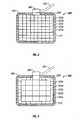
- FIG. 2is a plan view of an electrosurgical return electrode according to an embodiment of the present disclosure, illustrating a conductive pad having a grid of conductive elements of substantially equal sizes;
- FIG. 3is a plan view of an electrosurgical return electrode according to an embodiment of the present disclosure, illustrating a conductive pad having a grid of conductive elements of various sizes;
- FIG. 4is an enlarged schematic cross-sectional view of a portion of the return electrodes of FIGS. 1-3 .
- the electrosurgical systemgenerally includes a return electrode 200, a connection device 300 for connecting the return electrode 200 to a generator 120, and a plurality of temperature sensors 400 disposed on or operatively associated with the return electrode 200 ( FIG. 4 ).
- the return electrode 200is illustrated placed under a patient "P.”
- the plurality of temperature sensors 400are in operative engagement with the return electrode 200 and operatively connect to the connection device 300 via a second cable 250.
- the connection device 300may be operatively connected to the generator 120 ( FIG. 1 ), may be operatively connected to the return electrode 200 ( FIGS. 2 and 3 ), or may be disposed between the return electrode 200 and a generator 120 ( FIG. 4 ).
- a surgical instrumentfor treating tissue at the surgical site is designated by reference number 110.
- Electrosurgical energyis supplied to the surgical instrument 110 by the generator 120 via a first cable 130 to cut, coagulate, blend, etc. tissue.
- the return electrode 200returns the excess energy delivered by the surgical instrument 110 to the patient "P" back to the generator 120 via a wire 140. It is envisioned for the wire 140 to be incorporated into the second cable 250.
- FIGS. 2, 3 and 4illustrate various embodiments of the return electrode 200 for use in monopolar electrosurgery.
- the return electrode 200is a conductive pad 210 having a top surface 212 ( FIG. 4 ) and a bottom surface 214 ( FIG. 4 ).
- the return electrode 200is designed and configured to receive current during monopolar electrosurgery. While the figures depict the return electrode 200 in a general rectangular shape, it is within the scope of the disclosure for the return electrode 200 to have any regular or irregular shape.
- the conductive pad 210is comprised of a plurality of conductive elements (only conductive elements 220a - 220f are labeled for clarity) arranged in a regular or irregular array.
- Each of the plurality of conductive elements 220may be equally-sized or differently-sized and may form a grid/array or be disposed in any other grid-like arrangement on the conductive pad 210. It is also envisioned and within the scope of the present disclosure for the plurality of conductive elements 220 to be arranged in a spiral or radial orientation (not shown) on the conductive pad 210. While the figures depict the conductive elements 220 in a generally rectangular shape, it is within the scope of the present disclosure for the conductive elements 220 to have any regular or irregular shape.
- the plurality of temperature sensors 400include individual temperature sensors (illustrated as 400a-400f , corresponding to conductive elements 220a - 220f, respectively), which are able to measure the temperature of a patient's skin in contact therewith.
- the plurality of temperature sensors 400are operatively connected to the plurality of conductive elements 220 on the top surface 212 of the conductive pad 210.
- one of the plurality of temperature sensors 400is operatively connected to one of the plurality of conductive elements 220.
- individual temperature sensor 400amay be operatively connected to conductive element 220a.
- Each of the plurality of temperature sensors 400is connected to the connection device 300 via a respective second cable 250.
- temperature sensor 400amay be connected to the connection device 300 via second cable 250a.
- each of the second cables 250 connected to each of the temperature sensors 400is not illustrated in FIGS. 2 and 3 .
- the area of the return electrode 200 that is in contact with the patient "P"affects the current density of a signal that heats the patient "P.”
- the greater the contact area of the return electrode 200the smaller the current density and the less heating of the tissue.
- the greater the heating of the tissuethe greater the probability of burning the tissue. It is therefore important to either ensure a relative high amount of contact area between the return electrode 200 and the patient "P,” or otherwise maintain a relatively low current density on the return electrode 200.
- While there are various methods of maintaining a relatively low current densityincluding, inter alia, the use of electrosurgical return electrode monitors (REMs), such as the one described in commonly-owned U.S. Patent No. 6,565,559 ), the present disclosure ensures the return electrode 200 maintains a low current density by monitoring the temperature of each of the plurality of conductive elements 220 of the return electrode 200.
- REMselectrosurgical return electrode monitors
- Each temperature sensor 400 of the present disclosurehas the ability to measure the temperature of the patient "P" that is in contact therewith.
- each conductive element 220 of the present disclosuremay be connected and/or disconnected to the connection device 300 or may be activated and/or deactivated as needed, or may be adjusted as needed.
- that conductive element 220may either be connected, disconnected, activated, deactivated or adjusted as needed. For example, if a conductive element (e.g., 220a ) along the perimeter of the conductive pad 210 becomes relatively hot, that conductive element 220a may be disconnected from the connection device 300, deactivated or adjusted to receive a lower amount of energy.
- the conductive element 220awould not receive any more energy or receive a reduced amount of energy and the temperature in the area of the patient "P" contacting the conductive element 220a would consequently no longer rise. It is envisioned and within the scope of the present disclosure for the disconnection/re-connection, deactivation/reactivation of the conductive elements 220 to occur automatically as a result of an algorithm or the like provided in the electrosurgical generator 120.
- a disconnected conductive elemente.g., 220a
- a relatively lower temperaturei.e., cools down
- the temperature of the return electrode 200can be relatively consistent throughout the entire surface thereof, thus reducing the possibility of "hot spots" and patient burns.
- portions of the perimeter of the return electrode 200may become hot at a faster rate than the center of the return electrode 200.
- Monitoring the temperature of the patient "P" in contact with the smaller conductive elements 220would allow greater control of the overall temperature of the portions of the patient "P" in contact with the return electrode 200.
- the return electrode 200as a whole, would be able to receive a greater amount of current, as some new procedures necessitate.
- an adhesive layer 500to be disposed on the return electrode 200, as illustrated in FIGS. 2 and 3 .
- the adhesive layer 500may be conductive and may be made from materials that include, but are not limited to, a polyhesive adhesive; a Z axis adhesive; or a water-insoluble, hydrophilic, pressure-sensitive adhesive and is desirably made of a polyhesive adhesive. Such materials are described in U.S. Patent Nos. 4,699,146 and 4,750,482 .
- a function of the adhesive layer 500is to ensure an optimal surface contact area between the return electrode 200 and the patient "P" and thus to limit the possibility of a patient burn.
- the return electrode 200it is envisioned for the return electrode 200 to be entirely disposable, entirely re-usable, or a combination thereof.
- the conductive elements 220are re-usable, while the adhesive layer 500 is disposable.
- Other combinations of disposable/reusable portions of the return electrode 200are envisioned and within the scope of the present disclosure.
- a multiplexer 260may be employed to control switching of the plurality of conductive elements 220, as illustrated in Fig. 4 .
- the multiplexer 260may be configured to regulate the current in any fashion by switching on and off various amounts of the plurality of conductive elements 220. While the multiplexer 260 is illustrated between the generator 120 and the connection device 300, other locations for the multiplexer 260 are envisioned and within the scope of the present disclosure.
- the methodincludes providing a return electrode 200 as described above; placing the return electrode 200 in contact with a patient "P”; generating electrosurgical energy via the generator 120; supplying the electrosurgical energy to the patient “P” via the active electrode 110; measuring the temperature of the portions of the patient “P” in contact with the plurality of conductive elements 220 via the plurality of temperature sensors 400; and monitoring the temperature of the portions of the patient “P” in contact with the plurality of conductive elements 220.
- a conductive elemente.g., 220a
- a conductive elemente.g., 220a
- connection device 300may be connected (or reconnected) to the connection device 300, or re-activated when the portion of the patient "P" in contact with that conductive element 220b falls to a predetermined temperature.
- this methodcan be utilized to maintain a relatively constant temperature where the return electrode 200 contacts the patient "P.”
- the return electrode 200may be at least partially coated with a positive temperature coefficient (PTC) material to help distribute the heat across the return electrode 200.
- PTCpositive temperature coefficient
Landscapes
- Health & Medical Sciences (AREA)
- Surgery (AREA)
- Engineering & Computer Science (AREA)
- Life Sciences & Earth Sciences (AREA)
- Biomedical Technology (AREA)
- Otolaryngology (AREA)
- Nuclear Medicine, Radiotherapy & Molecular Imaging (AREA)
- Plasma & Fusion (AREA)
- Physics & Mathematics (AREA)
- Heart & Thoracic Surgery (AREA)
- Medical Informatics (AREA)
- Molecular Biology (AREA)
- Animal Behavior & Ethology (AREA)
- General Health & Medical Sciences (AREA)
- Public Health (AREA)
- Veterinary Medicine (AREA)
- Surgical Instruments (AREA)
Description
- The present disclosure is directed to an electrosurgical apparatus and, is particularly directed to a patient return electrode pad containing grids and an apparatus for performing monopolar surgery using the same.
- During electrosurgery, a source or active electrode delivers energy, such as radio frequency energy, from an electrosurgical generator to a patient. A return electrode carries the current back to the electrosurgical generator. In monopolar electrosurgery, the source electrode is typically a hand-held instrument placed by the surgeon at the surgical site and the high current density flow at this electrode creates the desired surgical effect of cutting and/or coagulating tissue. The patient return electrode is placed at a remote site from the source electrode and is typically in the form of a pad adhesively adhered to the patient.
- The return electrode typically has a relatively large patient contact surface area to minimize heating at that site because the smaller the surface area, the greater the current density and the greater the intensity of the heat. That is, the area of the return electrode that is adhered to the patient is generally important because it is the current density of the electrical signal that heats the tissue. A larger surface contact area is desirable to reduce heat intensity. The size of return electrodes is based on assumptions of the maximum current seen in surgery and the duty cycle (e.g., the percentage of time the generator is on) during the procedure. The first types of return electrodes were in the form of large metal plates covered with conductive jelly. Later, adhesive electrodes were developed with a single metal foil covered with conductive jelly or conductive adhesive. However, one problem with these adhesive electrodes was that if a portion peeled from the patient, the contact area of the electrode with the patient decreased, thereby increasing the current density at the adhered portion and, in turn, increasing the heat applied to the tissue. This risked burning the patient in the area under the adhered portion of the return electrode if the tissue was heated beyond the point where circulation of blood could cool the skin.
- To address this problem, split return electrodes and hardware circuits, generically called Return Electrode Contact Quality Monitors (RECQMs), were developed. These split electrodes consist of two separate conductive foils arranged as two halves of a single return electrode. The hardware circuit uses an AC signal between the two electrode halves to measure the impedance therebetween. This impedance measurement is indicative of how well the return electrode is adhered to the patient since the impedance between the two halves is directly related to the area of patient contact. That is, if the electrode begins to peel from the patient, the impedance increases since the contact area of the electrode decreases. Current RECQMs are designed to sense this change in impedance so that when the percentage increase in impedance exceeds a predetermined value or the measured impedance exceeds a threshold level, the electrosurgical generator is shut down to reduce the chances of burning the patient.
- As new surgical procedures continue to be developed that utilize higher current and higher duty cycles, increased heating of tissue under the return electrode may occur. It would therefore be advantageous to design a return electrode pad which has the ability of reducing the likelihood of patient burns, while still being able to dissipate an increased amount of heat.
US-A-4 343 308 discloses an electrosurgical grounding pad with a temperature sensor. As the temperature of the grounding pad approaches a potentially dangerous level, an alarm indicates to operating room personnel the possible burn condition.EP 1 051 949 discloses an electrosurgical return electrode monitor. The preamble of claim 1 is based on this document. - The present disclosure provides an electrosurgical return electrode for use in monopolar surgery. The return electrode comprises a conductive pad including a plurality of conductive elements. The return electrode further includes a plurality of temperature sensors which are each operatively engaged with a respective one of the plurality of conductive elements on a top surface of the conductive pad and which measure the temperature of a portion of a patient in contact with the respective conductive element.
- The present disclosure may also include a connection device which selectively enables the transfer of radio frequency current from an active electrode to at least one of the plurality of conductive elements. In operation, the connection device may be connected, disconnected, activated, deactivated and/or adjusted to a conductive element when the temperature of the patient in contact with the respective conductive element reaches a predetermined level. Specifically, if the temperature of a portion of the patient is too high, the conductive element contacting the patient at that location may be disconnected from the connection device. If the temperature of a portion of the patient in contact with a conductive element is cool enough, the conductive element in that location can be connected (or reconnected) to the connection device.
- It is envisioned for the plurality of conductive elements to form a grid. Additionally, each of the conductive elements may be approximately the same size. Alternatively, certain conductive elements may be a different size from the rest. For example, the conductive elements around the perimeter of the conductive pad may be relatively smaller than the remainder of the conductive elements.
- In an embodiment, an adhesive portion is included on the electrosurgical return electrode which facilitates the adhesion between at least a portion of the conductive pad and a patient. This adhesive portion may be capable of conducting electricity.
- In a particularly useful embodiment, the connection device is connectable to an electrosurgical generator and to each of the plurality of the conductive elements.
- It is envisioned for each of the temperature sensors to be able to measure the temperature of a patient's skin in contact therewith and/or in contact with the corresponding conductive element.
- The connection device may be located on the conductive pad, on an electrosurgical generator, or at a location between the conductive pad and the electrosurgical generator.
- It is envisioned for the electrosurgical return electrode to be entirely disposable, partially disposable, or entirely re-usable. It is further envisioned for some portions of the electrosurgical return electrode to be disposable and for some portions to be re-usable. For example, the conductive elements may be re-usable, while an adhesive may be disposable.
- The present disclosure also provides an electrosurgical apparatus for performing electrosurgery on a patient according to claim 12.
- For a better understanding of the present disclosure and to show how it may be carried into effect, reference will now be made by way of example to the accompanying drawings.
- The above and other aspects, features, and advantages of the present disclosure will become more apparent in light of the following detailed description when taken in conjunction with the accompanying drawings in which:
FIG. 1 is a schematic illustration of a monopolar electrosurgical system;FIG. 2 is a plan view of an electrosurgical return electrode according to an embodiment of the present disclosure, illustrating a conductive pad having a grid of conductive elements of substantially equal sizes;FIG. 3 is a plan view of an electrosurgical return electrode according to an embodiment of the present disclosure, illustrating a conductive pad having a grid of conductive elements of various sizes; andFIG. 4 is an enlarged schematic cross-sectional view of a portion of the return electrodes ofFIGS. 1-3 .- Embodiments of the presently disclosed temperature regulating patient return electrode of using the same will be described herein below with reference to the accompanying drawing figures wherein like reference numerals identify similar or identical elements. In the following description, well-known functions or constructions are not described in detail to avoid obscuring the disclosure in unnecessary detail.
- Referring initially to
FIG. 1 , a schematic illustration of a monopolarelectrosurgical system 100 is shown. The electrosurgical system generally includes areturn electrode 200, aconnection device 300 for connecting thereturn electrode 200 to agenerator 120, and a plurality oftemperature sensors 400 disposed on or operatively associated with the return electrode 200 (FIG. 4 ). InFIG. 1 , thereturn electrode 200 is illustrated placed under a patient "P." The plurality oftemperature sensors 400 are in operative engagement with thereturn electrode 200 and operatively connect to theconnection device 300 via asecond cable 250. Theconnection device 300 may be operatively connected to the generator 120 (FIG. 1 ), may be operatively connected to the return electrode 200 (FIGS. 2 and 3 ), or may be disposed between thereturn electrode 200 and a generator 120 (FIG. 4 ). - A surgical instrument (e.g., an active electrode) for treating tissue at the surgical site is designated by
reference number 110. Electrosurgical energy is supplied to thesurgical instrument 110 by thegenerator 120 via afirst cable 130 to cut, coagulate, blend, etc. tissue. Thereturn electrode 200 returns the excess energy delivered by thesurgical instrument 110 to the patient "P" back to thegenerator 120 via awire 140. It is envisioned for thewire 140 to be incorporated into thesecond cable 250. FIGS. 2, 3 and4 illustrate various embodiments of thereturn electrode 200 for use in monopolar electrosurgery. Generally, thereturn electrode 200 is aconductive pad 210 having a top surface 212 (FIG. 4 ) and a bottom surface 214 (FIG. 4 ). Thereturn electrode 200 is designed and configured to receive current during monopolar electrosurgery. While the figures depict thereturn electrode 200 in a general rectangular shape, it is within the scope of the disclosure for thereturn electrode 200 to have any regular or irregular shape.- As illustrated in
FIGS. 2, 3 and4 , theconductive pad 210 is comprised of a plurality of conductive elements (onlyconductive elements 220a - 220f are labeled for clarity) arranged in a regular or irregular array. Each of the plurality of conductive elements 220 may be equally-sized or differently-sized and may form a grid/array or be disposed in any other grid-like arrangement on theconductive pad 210. It is also envisioned and within the scope of the present disclosure for the plurality of conductive elements 220 to be arranged in a spiral or radial orientation (not shown) on theconductive pad 210. While the figures depict the conductive elements 220 in a generally rectangular shape, it is within the scope of the present disclosure for the conductive elements 220 to have any regular or irregular shape. - As illustrated in
FIG. 4 , the plurality oftemperature sensors 400 include individual temperature sensors (illustrated as 400a-400f , corresponding toconductive elements 220a - 220f, respectively), which are able to measure the temperature of a patient's skin in contact therewith. The plurality oftemperature sensors 400 are operatively connected to the plurality of conductive elements 220 on thetop surface 212 of theconductive pad 210. In such an arrangement, one of the plurality oftemperature sensors 400 is operatively connected to one of the plurality of conductive elements 220. For example,individual temperature sensor 400a may be operatively connected toconductive element 220a. Each of the plurality oftemperature sensors 400 is connected to theconnection device 300 via a respectivesecond cable 250. For example,temperature sensor 400a may be connected to theconnection device 300 viasecond cable 250a. In the interest of clarity, each of thesecond cables 250 connected to each of thetemperature sensors 400 is not illustrated inFIGS. 2 and 3 . - Generally, the area of the
return electrode 200 that is in contact with the patient "P" affects the current density of a signal that heats the patient "P." The smaller the contact area thereturn electrode 200 has with the patient "P," the greater the current density and the greater and more concentrated the heating of tissue is. Conversely, the greater the contact area of thereturn electrode 200, the smaller the current density and the less heating of the tissue. Further, the greater the heating of the tissue, the greater the probability of burning the tissue. It is therefore important to either ensure a relative high amount of contact area between thereturn electrode 200 and the patient "P," or otherwise maintain a relatively low current density on thereturn electrode 200. - While there are various methods of maintaining a relatively low current density (including, inter alia, the use of electrosurgical return electrode monitors (REMs), such as the one described in commonly-owned
U.S. Patent No. 6,565,559 ), the present disclosure ensures thereturn electrode 200 maintains a low current density by monitoring the temperature of each of the plurality of conductive elements 220 of thereturn electrode 200. - Each
temperature sensor 400 of the present disclosure has the ability to measure the temperature of the patient "P" that is in contact therewith. Further, each conductive element 220 of the present disclosure may be connected and/or disconnected to theconnection device 300 or may be activated and/or deactivated as needed, or may be adjusted as needed. When the temperature of the patient "P" in contact with a particular conductive element 220 reaches a predetermined level, that conductive element 220 may either be connected, disconnected, activated, deactivated or adjusted as needed. For example, if a conductive element (e.g., 220a ) along the perimeter of theconductive pad 210 becomes relatively hot, thatconductive element 220a may be disconnected from theconnection device 300, deactivated or adjusted to receive a lower amount of energy. In this example, theconductive element 220a would not receive any more energy or receive a reduced amount of energy and the temperature in the area of the patient "P" contacting theconductive element 220a would consequently no longer rise. It is envisioned and within the scope of the present disclosure for the disconnection/re-connection, deactivation/reactivation of the conductive elements 220 to occur automatically as a result of an algorithm or the like provided in theelectrosurgical generator 120. - It is also envisioned and within the scope of the present disclosure for a disconnected conductive element, e.g., 220a, to be reconnected to the
connection device 300 when the temperature of the patient "P" in contact with thecorresponding temperature sensor 400a falls to a relatively lower temperature (i.e., cools down). Utilizing these features, the temperature of thereturn electrode 200 can be relatively consistent throughout the entire surface thereof, thus reducing the possibility of "hot spots" and patient burns. - During electrosurgical use of the
return electrode 200, portions of the perimeter of thereturn electrode 200 may become hot at a faster rate than the center of thereturn electrode 200. In such a situation, as seen inFIG. 3 , it may be desirable to have the conductive elements 220 near the perimeter of thereturn electrode 200 be smaller than the remaining conductive elements 220. Monitoring the temperature of the patient "P" in contact with the smaller conductive elements 220 would allow greater control of the overall temperature of the portions of the patient "P" in contact with thereturn electrode 200. Thus, thereturn electrode 200, as a whole, would be able to receive a greater amount of current, as some new procedures necessitate. - To further limit the possibility of patient burns, it is envisioned for an
adhesive layer 500 to be disposed on thereturn electrode 200, as illustrated inFIGS. 2 and 3 . Theadhesive layer 500 may be conductive and may be made from materials that include, but are not limited to, a polyhesive adhesive; a Z axis adhesive; or a water-insoluble, hydrophilic, pressure-sensitive adhesive and is desirably made of a polyhesive adhesive. Such materials are described inU.S. Patent Nos. 4,699,146 and4,750,482 . A function of theadhesive layer 500 is to ensure an optimal surface contact area between thereturn electrode 200 and the patient "P" and thus to limit the possibility of a patient burn. - It is envisioned for the
return electrode 200 to be entirely disposable, entirely re-usable, or a combination thereof. In one embodiment, the conductive elements 220 are re-usable, while theadhesive layer 500 is disposable. Other combinations of disposable/reusable portions of thereturn electrode 200 are envisioned and within the scope of the present disclosure. - It is envisioned that a
multiplexer 260 may be employed to control switching of the plurality of conductive elements 220, as illustrated inFig. 4 . For example, it is envisioned that themultiplexer 260 may be configured to regulate the current in any fashion by switching on and off various amounts of the plurality of conductive elements 220. While themultiplexer 260 is illustrated between thegenerator 120 and theconnection device 300, other locations for themultiplexer 260 are envisioned and within the scope of the present disclosure. - There is also disclosed a method of performing monopolar electrosurgery. The method includes providing a
return electrode 200 as described above; placing thereturn electrode 200 in contact with a patient "P"; generating electrosurgical energy via thegenerator 120; supplying the electrosurgical energy to the patient "P" via theactive electrode 110; measuring the temperature of the portions of the patient "P" in contact with the plurality of conductive elements 220 via the plurality oftemperature sensors 400; and monitoring the temperature of the portions of the patient "P" in contact with the plurality of conductive elements 220. Utilizing this method, a conductive element (e.g., 220a) may be disconnected or deactivated from theconnection device 300 when the portion of the patient "P" in contact with theconductive element 220a reaches a predetermined temperature. Additionally, a conductive element (e.g., 220a) may be connected (or reconnected) to theconnection device 300, or re-activated when the portion of the patient "P" in contact with thatconductive element 220b falls to a predetermined temperature. As can be appreciated, this method can be utilized to maintain a relatively constant temperature where thereturn electrode 200 contacts the patient "P." - While several embodiments of the disclosure have been shown in the drawings, the above description should be construed merely as exemplifications of preferred embodiments. For example, it is envisioned for the
return electrode 200 to be at least partially coated with a positive temperature coefficient (PTC) material to help distribute the heat across thereturn electrode 200.
Claims (15)
- An electrosurgical return electrode pad (200) for use in monopolar surgery, comprising:a conductive pad (210) including a plurality of conductive elements (220a-220f) and having a top surface (212) and a bottom surface (214), the conductive pad defining a perimeter;characterised in that:the return electrode further comprises a plurality of temperature sensors, each temperature sensor being operatively engaged with a respective one of the plurality of conductive elements (220a-220f) on the top surface of the conductive pad, wherein each temperature sensor is configured to measure a temperature of a portion of a patient(P) in contact with the respective conductive element (220a-220f).
- The electrosurgical return electrode (200) according to claim 1, further comprising a connection device (300) which selectively enables the transfer of radio frequency energy from an active electrode to at least one of the plurality of conductive elements (220a-220f), wherein the connection device (300) may be at least one of connected, disconnected, activated, deactivated and adjusted to a conductive element when the temperature of a corresponding portion of the patient (P) reaches a predetermined level.
- The electrosurgical return electrode (200) according to any of the preceding claims, wherein the plurality of conductive elements (220a-220f) forms a grid.
- The electrosurgical return electrode (200) according to any of the preceding claims, wherein each of the plurality of conductive elements (220a-220f) is approximately the same size.
- The electrosurgical return electrode (200) according to any of claims 1 to 3, wherein at least one of the plurality of conductive elements (220a-220f) is a different size than the remainder of the conductive elements.
- The electrosurgical return electrode (200) according to claim 5, wherein the conductive elements (220a-220f) along the perimeter of the conductive pad are relatively smaller than the remainder of the conductive elements.
- The electrosurgical return electrode (200) according to any of the preceding claims, further comprising an adhesive portion (500) which adheres at least a portion of the conductive pad (210) to a patient (P).
- The electrosurgical return electrode (200) according to claim 2 or any of claims 3 to 7 when dependent on claim 2, wherein the connection device (300) transfers radio frequency energy from an active electrode to each of the plurality of conductive elements (220a-220f).
- The electrosurgical return electrode (200) according to any of the preceding claims, wherein each temperature sensor (400a-400f) is adapted to contact a patient (P).
- The electrosurgical return electrode (200) according to claim 2 or any of claims 3 to 9 when dependent on claim 2, wherein the connection device (300) is i) disposed on the conductive pad (210) ii) disposed on an electrosurgical generator (120) or iii) disposed between the conductive pad (210) and an electrosurgical generator (120).
- The electrosurgical return electrode (200) according to claim 2 or any of claims 3 to 7 when dependent on claim 2, further comprising a multiplexer (260) that is disposed adjacent the connection device (300) and that controls switching of the plurality of conductive, elements (220a-220f).
- An electrosurgical apparatus (100) for performing electrosurgery on a patient (P), the electrosurgical apparatus comprising:an electrosurgical generator (120) to produce electrosurgical energy;characterised in that the apparatus comprisesan electrosurgical return electrode (200) according.to any one of the preceding claims that is selectively connectable to the electrosurgical generator (120).
- The electrosurgical apparatus of claim 12 for performing monopolar surgery, comprising:an active electrode for supplying the electrosurgical energy to the patient.
- The electrosurgical apparatus of claim 12 or 13, the electrosurgical generator configured to monitor the temperature of each portion of a patient in contact with the respective conductive element and to disconnect or deactivate an element if the temperature reaches a predetermined level.
- The electrosurgical apparatus of claim 14, the electrosurgical generator configured to connect or activate an element if the temperature reaches a predetermined level.
Applications Claiming Priority (1)
| Application Number | Priority Date | Filing Date | Title |
|---|---|---|---|
| US11/218,110US20070049914A1 (en) | 2005-09-01 | 2005-09-01 | Return electrode pad with conductive element grid and method |
Publications (2)
| Publication Number | Publication Date |
|---|---|
| EP1759651A1 EP1759651A1 (en) | 2007-03-07 |
| EP1759651B1true EP1759651B1 (en) | 2009-08-26 |
Family
ID=37074199
Family Applications (1)
| Application Number | Title | Priority Date | Filing Date |
|---|---|---|---|
| EP06018206ANot-in-forceEP1759651B1 (en) | 2005-09-01 | 2006-08-31 | Return electrode pad with conductive element grid |
Country Status (5)
| Country | Link |
|---|---|
| US (1) | US20070049914A1 (en) |
| EP (1) | EP1759651B1 (en) |
| CA (1) | CA2556496A1 (en) |
| DE (1) | DE602006008710D1 (en) |
| ES (1) | ES2330775T3 (en) |
Cited By (1)
| Publication number | Priority date | Publication date | Assignee | Title |
|---|---|---|---|---|
| DE102020003524A1 (en) | 2020-06-12 | 2021-12-16 | Coco Beteiligungsgesellschaft mbH | Monitoring unit and high-frequency surgical system with such a monitoring unit |
Families Citing this family (40)
| Publication number | Priority date | Publication date | Assignee | Title |
|---|---|---|---|---|
| AU2002303942B2 (en)* | 2001-06-01 | 2006-06-22 | Covidien Ag | Return pad cable connector |
| JP2005533607A (en) | 2002-07-25 | 2005-11-10 | シャーウッド・サービシーズ・アクチェンゲゼルシャフト | Electrosurgical pencil with drag detection |
| US6860881B2 (en) | 2002-09-25 | 2005-03-01 | Sherwood Services Ag | Multiple RF return pad contact detection system |
| CA2542849C (en)* | 2003-10-23 | 2013-08-20 | Sherwood Services Ag | Redundant temperature monitoring in electrosurgical systems for safety mitigation |
| CA2541037A1 (en) | 2005-03-31 | 2006-09-30 | Sherwood Services Ag | Temperature regulating patient return electrode and return electrode monitoring system |
| US7500974B2 (en) | 2005-06-28 | 2009-03-10 | Covidien Ag | Electrode with rotatably deployable sheath |
| US7736359B2 (en)* | 2006-01-12 | 2010-06-15 | Covidien Ag | RF return pad current detection system |
| US20070244478A1 (en)* | 2006-04-18 | 2007-10-18 | Sherwood Services Ag | System and method for reducing patient return electrode current concentrations |
| CN101505668A (en)* | 2006-06-20 | 2009-08-12 | 奥尔特克斯公司 | Prosthetic valve implant site preparation techniques |
| US20080051777A1 (en)* | 2006-08-28 | 2008-02-28 | Dieter Haemmerich | Radiofrequency ablation device for reducing the incidence of skin burns |
| US7637907B2 (en) | 2006-09-19 | 2009-12-29 | Covidien Ag | System and method for return electrode monitoring |
| US7722603B2 (en)* | 2006-09-28 | 2010-05-25 | Covidien Ag | Smart return electrode pad |
| US7927329B2 (en)* | 2006-09-28 | 2011-04-19 | Covidien Ag | Temperature sensing return electrode pad |
| US20080228180A1 (en)* | 2007-03-13 | 2008-09-18 | Halt Medical, Inc | Ablation system and heat preventing electrodes therefor |
| US8021360B2 (en)* | 2007-04-03 | 2011-09-20 | Tyco Healthcare Group Lp | System and method for providing even heat distribution and cooling return pads |
| US20080249524A1 (en)* | 2007-04-03 | 2008-10-09 | Tyco Healthcare Group Lp | System and method for providing even heat distribution and cooling return pads |
| US8777940B2 (en) | 2007-04-03 | 2014-07-15 | Covidien Lp | System and method for providing even heat distribution and cooling return pads |
| US8080007B2 (en)* | 2007-05-07 | 2011-12-20 | Tyco Healthcare Group Lp | Capacitive electrosurgical return pad with contact quality monitoring |
| US8231614B2 (en)* | 2007-05-11 | 2012-07-31 | Tyco Healthcare Group Lp | Temperature monitoring return electrode |
| US8388612B2 (en)* | 2007-05-11 | 2013-03-05 | Covidien Lp | Temperature monitoring return electrode |
| AU2015203526B2 (en)* | 2007-05-11 | 2016-10-20 | Covidien Lp | Temperature monitoring return electrode |
| US20080312651A1 (en)* | 2007-06-15 | 2008-12-18 | Karl Pope | Apparatus and methods for selective heating of tissue |
| US8801703B2 (en) | 2007-08-01 | 2014-08-12 | Covidien Lp | System and method for return electrode monitoring |
| US8100898B2 (en) | 2007-08-01 | 2012-01-24 | Tyco Healthcare Group Lp | System and method for return electrode monitoring |
| US20090171341A1 (en)* | 2007-12-28 | 2009-07-02 | Karl Pope | Dispersive return electrode and methods |
| US8343144B2 (en)* | 2008-02-11 | 2013-01-01 | Expandoheat, Llc | Apparatus and method for vessel sealing and tissue coagulation |
| US8486059B2 (en)* | 2008-02-15 | 2013-07-16 | Covidien Lp | Multi-layer return electrode |
| US8172835B2 (en) | 2008-06-05 | 2012-05-08 | Cutera, Inc. | Subcutaneous electric field distribution system and methods |
| US20090306647A1 (en)* | 2008-06-05 | 2009-12-10 | Greg Leyh | Dynamically controllable multi-electrode apparatus & methods |
| US20100022999A1 (en)* | 2008-07-24 | 2010-01-28 | Gollnick David A | Symmetrical rf electrosurgical system and methods |
| DE102009013917A1 (en)* | 2008-10-30 | 2010-05-12 | Erbe Elektromedizin Gmbh | Electrosurgical device with a temperature measuring device, method for determining a temperature and / or a temperature change at a neutral electrode |
| US8211097B2 (en)* | 2009-02-13 | 2012-07-03 | Cutera, Inc. | Optimizing RF power spatial distribution using frequency control |
| US9192430B2 (en)* | 2009-05-01 | 2015-11-24 | Covidien Lp | Electrosurgical instrument with time limit circuit |
| US20110238058A1 (en)* | 2010-03-29 | 2011-09-29 | Estech, Inc. (Endoscopic Technologies, Inc.) | Indifferent electrode pad systems and methods for tissue ablation |
| US9566109B2 (en) | 2013-07-18 | 2017-02-14 | Covidien Lp | Limited-use surgical devices |
| US10874457B2 (en) | 2016-09-27 | 2020-12-29 | Cardiac Pacemakers, Inc. | Segmented ground pads for electrophysiology systems |
| US11504179B2 (en) | 2019-06-25 | 2022-11-22 | Covidien Lp | Electrosurgical plug for energy activation of surgical instruments |
| US11452559B2 (en) | 2019-06-25 | 2022-09-27 | Covidien Lp | Electrosurgical plug for energy activation of surgical instruments |
| EP3847986A1 (en)* | 2020-01-13 | 2021-07-14 | Erbe Elektromedizin GmbH | Neutral electrode and method for producing same |
| AT527092A1 (en)* | 2023-04-03 | 2024-10-15 | Leonh Lang Holding Gmbh | Measuring device for measuring a temperature at a medical electrode |
Family Cites Families (100)
| Publication number | Priority date | Publication date | Assignee | Title |
|---|---|---|---|---|
| GB617203A (en)* | 1945-07-11 | 1949-02-02 | Philips Nv | Improvements in or relating to high-frequency energy devices for medical purposes |
| US3642008A (en)* | 1968-09-25 | 1972-02-15 | Medical Plastics Inc | Ground electrode and test circuit |
| US3933157A (en)* | 1973-10-23 | 1976-01-20 | Aktiebolaget Stille-Werner | Test and control device for electrosurgical apparatus |
| US4067342A (en)* | 1976-04-06 | 1978-01-10 | Medtronic, Inc. | Tape electrode |
| US4188927A (en)* | 1978-01-12 | 1980-02-19 | Valleylab, Inc. | Multiple source electrosurgical generator |
| US4314559A (en)* | 1979-12-12 | 1982-02-09 | Corning Glass Works | Nonstick conductive coating |
| US4494541A (en)* | 1980-01-17 | 1985-01-22 | Medical Plastics, Inc. | Electrosurgery safety monitor |
| US4343308A (en) | 1980-06-09 | 1982-08-10 | Gross Robert D | Surgical ground detector |
| US4895169A (en)* | 1980-08-08 | 1990-01-23 | Darox Corporation | Disposable non-invasive stimulating electrode set |
| US4562838A (en)* | 1981-01-23 | 1986-01-07 | Walker William S | Electrosurgery instrument |
| US4427006A (en)* | 1982-01-18 | 1984-01-24 | Medical Research Associates, Ltd. #1 | Electrosurgical instruments |
| US4699146A (en) | 1982-02-25 | 1987-10-13 | Valleylab, Inc. | Hydrophilic, elastomeric, pressure-sensitive adhesive |
| US4750482A (en) | 1982-02-25 | 1988-06-14 | Pfizer Inc. | Hydrophilic, elastomeric, pressure-sensitive adhesive |
| US4492231A (en)* | 1982-09-17 | 1985-01-08 | Auth David C | Non-sticking electrocautery system and forceps |
| US4725713A (en)* | 1982-10-22 | 1988-02-16 | Graco Inc. | Electrically heated hose employing a hose simulator for temperature control |
| US4643193A (en)* | 1985-06-04 | 1987-02-17 | C. R. Bard, Inc. | ECG electrode with sensing element having a conductive coating in a pattern thereon |
| US4640279A (en)* | 1985-08-08 | 1987-02-03 | Oximetrix, Inc. | Combination surgical scalpel and electrosurgical instrument |
| US4642128A (en)* | 1985-09-11 | 1987-02-10 | Xanar, Inc. | Smoke evacuator system with electronic control circuitry |
| DE8602882U1 (en)* | 1986-02-05 | 1986-04-03 | Preh, Elektrofeinmechanische Werke Jakob Preh Nachf. Gmbh & Co, 8740 Bad Neustadt | Electric hand control device |
| US4722761A (en)* | 1986-03-28 | 1988-02-02 | Baxter Travenol Laboratories, Inc. | Method of making a medical electrode |
| US4901719A (en)* | 1986-04-08 | 1990-02-20 | C. R. Bard, Inc. | Electrosurgical conductive gas stream equipment |
| US4988334A (en)* | 1986-04-09 | 1991-01-29 | Valleylab, Inc. | Ultrasonic surgical system with aspiration tubulation connector |
| US4807621A (en)* | 1987-06-03 | 1989-02-28 | Siemens Aktiengesellschaft | Multi-element flat electrode especially useful for HF-surgery |
| US4799480A (en)* | 1987-08-04 | 1989-01-24 | Conmed | Electrode for electrosurgical apparatus |
| US4903696A (en)* | 1988-10-06 | 1990-02-27 | Everest Medical Corporation | Electrosurgical generator |
| US4986839A (en)* | 1988-11-10 | 1991-01-22 | Surgical Laser Products, Inc. | Self-contained air enhancement and laser plume evacuation system |
| EP0390937B1 (en)* | 1989-04-01 | 1994-11-02 | Erbe Elektromedizin GmbH | Device for the surveillance of the adherence of neutral electrodes in high-frequency surgery |
| US5088997A (en)* | 1990-03-15 | 1992-02-18 | Valleylab, Inc. | Gas coagulation device |
| WO1991017027A1 (en)* | 1990-05-10 | 1991-11-14 | Buck Byron L | Rotary die cutting system for sheet material |
| US5599347A (en)* | 1991-02-13 | 1997-02-04 | Applied Medical Resources Corporation | Surgical trocar with cutoff circuit |
| US5286255A (en)* | 1991-07-29 | 1994-02-15 | Linvatec Corporation | Surgical forceps |
| US6022347A (en)* | 1991-08-12 | 2000-02-08 | Karl Storz Gmbh & Co. | High-frequency surgical generator for adjusted cutting and coagulation |
| US5178605A (en)* | 1991-09-23 | 1993-01-12 | Alcon Surgical, Inc. | Coaxial flow irrigating and aspirating ultrasonic handpiece |
| US5276079A (en)* | 1991-11-15 | 1994-01-04 | Minnesota Mining And Manufacturing Company | Pressure-sensitive poly(n-vinyl lactam) adhesive composition and method for producing and using same |
| AU652494B2 (en)* | 1991-11-15 | 1994-08-25 | Minnesota Mining And Manufacturing Company | Solid state conductive polymer compositions, biomedical electrodes containing such compositions, and method of preparing same |
| GB9125280D0 (en)* | 1991-11-28 | 1992-01-29 | Smiths Industries Plc | Patient support tables and monitors |
| US5601224A (en)* | 1992-10-09 | 1997-02-11 | Ethicon, Inc. | Surgical instrument |
| US5720745A (en)* | 1992-11-24 | 1998-02-24 | Erbe Electromedizin Gmbh | Electrosurgical unit and method for achieving coagulation of biological tissue |
| GB9306637D0 (en)* | 1993-03-30 | 1993-05-26 | Smiths Industries Plc | Electrosurgery monitor and appartus |
| JP3683909B2 (en)* | 1993-10-08 | 2005-08-17 | ロゴジンスキ,チェーム | Device for treating spinal conditions |
| US5380320A (en)* | 1993-11-08 | 1995-01-10 | Advanced Surgical Materials, Inc. | Electrosurgical instrument having a parylene coating |
| US5484434A (en)* | 1993-12-06 | 1996-01-16 | New Dimensions In Medicine, Inc. | Electrosurgical scalpel |
| US5382247A (en)* | 1994-01-21 | 1995-01-17 | Valleylab Inc. | Technique for electrosurgical tips and method of manufacture and use |
| US5484398A (en)* | 1994-03-17 | 1996-01-16 | Valleylab Inc. | Methods of making and using ultrasonic handpiece |
| US6030381A (en)* | 1994-03-18 | 2000-02-29 | Medicor Corporation | Composite dielectric coating for electrosurgical implements |
| US5540722A (en)* | 1994-05-16 | 1996-07-30 | Physiometrix, Inc. | Switch apparatus and method for switching between multiple electrodes for diagnostic and therapeutic procedures |
| US5713895A (en)* | 1994-12-30 | 1998-02-03 | Valleylab Inc | Partially coated electrodes |
| US5486162A (en)* | 1995-01-11 | 1996-01-23 | Fibrasonics, Inc. | Bubble control device for an ultrasonic surgical probe |
| US6409722B1 (en)* | 1998-07-07 | 2002-06-25 | Medtronic, Inc. | Apparatus and method for creating, maintaining, and controlling a virtual electrode used for the ablation of tissue |
| US6179837B1 (en)* | 1995-03-07 | 2001-01-30 | Enable Medical Corporation | Bipolar electrosurgical scissors |
| US5707369A (en)* | 1995-04-24 | 1998-01-13 | Ethicon Endo-Surgery, Inc. | Temperature feedback monitor for hemostatic surgical instrument |
| AU5841096A (en)* | 1995-05-31 | 1996-12-18 | Nuvotek Ltd | Electrosurgical cutting and coagulation apparatus |
| US5720744A (en)* | 1995-06-06 | 1998-02-24 | Valleylab Inc | Control system for neurosurgery |
| US5658302A (en)* | 1995-06-07 | 1997-08-19 | Baxter International Inc. | Method and device for endoluminal disruption of venous valves |
| US5868742A (en)* | 1995-10-18 | 1999-02-09 | Conmed Corporation | Auxiliary reference electrode and potential referencing technique for endoscopic electrosurgical instruments |
| US5712543A (en)* | 1995-10-31 | 1998-01-27 | Smith & Nephew Endoscopy Inc. | Magnetic switching element for controlling a surgical device |
| US7267675B2 (en)* | 1996-01-05 | 2007-09-11 | Thermage, Inc. | RF device with thermo-electric cooler |
| US7006874B2 (en)* | 1996-01-05 | 2006-02-28 | Thermage, Inc. | Treatment apparatus with electromagnetic energy delivery device and non-volatile memory |
| US7115123B2 (en)* | 1996-01-05 | 2006-10-03 | Thermage, Inc. | Handpiece with electrode and non-volatile memory |
| US20040000316A1 (en)* | 1996-01-05 | 2004-01-01 | Knowlton Edward W. | Methods for creating tissue effect utilizing electromagnetic energy and a reverse thermal gradient |
| US7473251B2 (en)* | 1996-01-05 | 2009-01-06 | Thermage, Inc. | Methods for creating tissue effect utilizing electromagnetic energy and a reverse thermal gradient |
| US6413255B1 (en)* | 1999-03-09 | 2002-07-02 | Thermage, Inc. | Apparatus and method for treatment of tissue |
| US6350276B1 (en)* | 1996-01-05 | 2002-02-26 | Thermage, Inc. | Tissue remodeling apparatus containing cooling fluid |
| US5601618A (en)* | 1996-02-26 | 1997-02-11 | James; Brian C. | Stimulation and heating device |
| AUPO044596A0 (en)* | 1996-06-14 | 1996-07-11 | Skop Gmbh Ltd | Improved electrical signal supply |
| US7166102B2 (en)* | 1996-10-30 | 2007-01-23 | Megadyne Medical Products, Inc. | Self-limiting electrosurgical return electrode |
| JP2001521420A (en)* | 1997-04-04 | 2001-11-06 | ミネソタ マイニング アンド マニュファクチャリング カンパニー | Method and apparatus for managing the state of contact of a biomedical electrode with patient skin |
| US6312426B1 (en)* | 1997-05-30 | 2001-11-06 | Sherwood Services Ag | Method and system for performing plate type radiofrequency ablation |
| US6032063A (en)* | 1997-12-09 | 2000-02-29 | Vital Connections, Inc. | Distributed resistance leadwire harness assembly for physiological monitoring during magnetic resonance imaging |
| US6068627A (en)* | 1997-12-10 | 2000-05-30 | Valleylab, Inc. | Smart recognition apparatus and method |
| US6461352B2 (en)* | 1999-05-11 | 2002-10-08 | Stryker Corporation | Surgical handpiece with self-sealing switch assembly |
| US6258085B1 (en) | 1999-05-11 | 2001-07-10 | Sherwood Services Ag | Electrosurgical return electrode monitor |
| US6471659B2 (en)* | 1999-12-27 | 2002-10-29 | Neothermia Corporation | Minimally invasive intact recovery of tissue |
| US7041101B2 (en)* | 1999-12-27 | 2006-05-09 | Neothermia Corporation | Electrosurgical accessing of tissue with controlled collateral thermal phenomena |
| US6347246B1 (en)* | 2000-02-03 | 2002-02-12 | Axelgaard Manufacturing Company, Ltd. | Electrotransport adhesive for iontophoresis device |
| DE60119002T2 (en)* | 2000-02-16 | 2006-11-23 | Sherwood Services Ag | Electrosurgical device with enriched inert gas |
| CA2299752A1 (en)* | 2000-02-28 | 2001-08-28 | Cst Coldswitch Technologies Inc. | Electro-surgical pencil with smoke evacuation |
| US6511479B2 (en)* | 2000-02-28 | 2003-01-28 | Conmed Corporation | Electrosurgical blade having directly adhered uniform coating of silicone release material and method of manufacturing same |
| USD453833S1 (en)* | 2001-01-24 | 2002-02-19 | Ethicon, Inc. | Handle for surgical instrument |
| USD453222S1 (en)* | 2001-04-30 | 2002-01-29 | Jon C. Garito | Electrosurgical handpiece |
| AU2002303942B2 (en)* | 2001-06-01 | 2006-06-22 | Covidien Ag | Return pad cable connector |
| US6796828B2 (en)* | 2001-06-01 | 2004-09-28 | Sherwood Services Ag | Return pad cable connector |
| US6923804B2 (en)* | 2001-07-12 | 2005-08-02 | Neothermia Corporation | Electrosurgical generator |
| US6652514B2 (en)* | 2001-09-13 | 2003-11-25 | Alan G. Ellman | Intelligent selection system for electrosurgical instrument |
| US6685704B2 (en)* | 2002-02-26 | 2004-02-03 | Megadyne Medical Products, Inc. | Utilization of an active catalyst in a surface coating of an electrosurgical instrument |
| US20040030330A1 (en)* | 2002-04-18 | 2004-02-12 | Brassell James L. | Electrosurgery systems |
| US20040015216A1 (en)* | 2002-05-30 | 2004-01-22 | Desisto Stephen R. | Self-evacuating electrocautery device |
| US6855140B2 (en)* | 2002-06-06 | 2005-02-15 | Thomas E. Albrecht | Method of tissue lesion removal |
| US6840948B2 (en)* | 2002-06-06 | 2005-01-11 | Ethicon-Endo Surgery, Inc. | Device for removal of tissue lesions |
| JP3905482B2 (en)* | 2002-07-09 | 2007-04-18 | オリンパス株式会社 | Surgery system |
| US6730079B2 (en)* | 2002-07-22 | 2004-05-04 | Medtronic Vidamed, Inc. | Method for calculating impedance and apparatus utilizing same |
| US6887237B2 (en)* | 2002-07-22 | 2005-05-03 | Medtronic, Inc. | Method for treating tissue with a wet electrode and apparatus for using same |
| US6855141B2 (en)* | 2002-07-22 | 2005-02-15 | Medtronic, Inc. | Method for monitoring impedance to control power and apparatus utilizing same |
| US6860881B2 (en)* | 2002-09-25 | 2005-03-01 | Sherwood Services Ag | Multiple RF return pad contact detection system |
| US6923809B2 (en)* | 2003-07-30 | 2005-08-02 | Neothermia Corporation | Minimally invasive instrumentation for recovering tissue |
| US7169145B2 (en)* | 2003-11-21 | 2007-01-30 | Megadyne Medical Products, Inc. | Tuned return electrode with matching inductor |
| US20060041252A1 (en)* | 2004-08-17 | 2006-02-23 | Odell Roger C | System and method for monitoring electrosurgical instruments |
| US7422589B2 (en)* | 2004-08-17 | 2008-09-09 | Encision, Inc. | System and method for performing an electrosurgical procedure |
| US7465302B2 (en)* | 2004-08-17 | 2008-12-16 | Encision, Inc. | System and method for performing an electrosurgical procedure |
| US20080009846A1 (en)* | 2006-07-06 | 2008-01-10 | Sherwood Services Ag | Electrosurgical return electrode with an involuted edge |
- 2005
- 2005-09-01USUS11/218,110patent/US20070049914A1/ennot_activeAbandoned
- 2006
- 2006-08-17CACA002556496Apatent/CA2556496A1/ennot_activeAbandoned
- 2006-08-31ESES06018206Tpatent/ES2330775T3/enactiveActive
- 2006-08-31DEDE602006008710Tpatent/DE602006008710D1/enactiveActive
- 2006-08-31EPEP06018206Apatent/EP1759651B1/ennot_activeNot-in-force
Cited By (2)
| Publication number | Priority date | Publication date | Assignee | Title |
|---|---|---|---|---|
| DE102020003524A1 (en) | 2020-06-12 | 2021-12-16 | Coco Beteiligungsgesellschaft mbH | Monitoring unit and high-frequency surgical system with such a monitoring unit |
| DE102020003524B4 (en) | 2020-06-12 | 2023-03-23 | Coco Beteiligungsgesellschaft mbH | Monitoring unit and high-frequency surgical system with such a monitoring unit |
Also Published As
| Publication number | Publication date |
|---|---|
| CA2556496A1 (en) | 2007-03-01 |
| US20070049914A1 (en) | 2007-03-01 |
| DE602006008710D1 (en) | 2009-10-08 |
| ES2330775T3 (en) | 2009-12-15 |
| EP1759651A1 (en) | 2007-03-07 |
Similar Documents
| Publication | Publication Date | Title |
|---|---|---|
| EP1759651B1 (en) | Return electrode pad with conductive element grid | |
| EP1707151B1 (en) | Temperature regulating patient return electrode and return electrode monitoring system | |
| EP1808144B1 (en) | RF return pad current detection system | |
| AU2007200187B2 (en) | RF return pad current distribution system | |
| CA2585107C (en) | System and method for reducing patient return electrode current concentrations | |
| EP2129312B1 (en) | Apparatus for moderating return electrode temperature | |
| EP1905374B1 (en) | Smart return electrode pad | |
| US20080009846A1 (en) | Electrosurgical return electrode with an involuted edge | |
| EP2223666B1 (en) | Devices for detecting heating under a patient return electrode | |
| EP1905372B1 (en) | Temperature sensing return electrode pad | |
| US20090171341A1 (en) | Dispersive return electrode and methods | |
| US20090138011A1 (en) | Intermittent ablation rf driving for moderating return electrode temperature | |
| US20090187177A1 (en) | Impedance responsive ablation rf driving for moderating return electrode temperature | |
| EP2087849B1 (en) | Hybrid contact quality monitoring return electrode | |
| WO2009094392A2 (en) | Intermittent ablation rf driving for moderating return electrode temperature |
Legal Events
| Date | Code | Title | Description |
|---|---|---|---|
| PUAI | Public reference made under article 153(3) epc to a published international application that has entered the european phase | Free format text:ORIGINAL CODE: 0009012 | |
| AK | Designated contracting states | Kind code of ref document:A1 Designated state(s):AT BE BG CH CY CZ DE DK EE ES FI FR GB GR HU IE IS IT LI LT LU LV MC NL PL PT RO SE SI SK TR | |
| AX | Request for extension of the european patent | Extension state:AL BA HR MK YU | |
| RAP1 | Party data changed (applicant data changed or rights of an application transferred) | Owner name:COVIDIEN AG | |
| 17P | Request for examination filed | Effective date:20070801 | |
| 17Q | First examination report despatched | Effective date:20070912 | |
| AKX | Designation fees paid | Designated state(s):DE ES FR GB IE IT | |
| RTI1 | Title (correction) | Free format text:RETURN ELECTRODE PAD WITH CONDUCTIVE ELEMENT GRID | |
| GRAP | Despatch of communication of intention to grant a patent | Free format text:ORIGINAL CODE: EPIDOSNIGR1 | |
| GRAS | Grant fee paid | Free format text:ORIGINAL CODE: EPIDOSNIGR3 | |
| GRAA | (expected) grant | Free format text:ORIGINAL CODE: 0009210 | |
| AK | Designated contracting states | Kind code of ref document:B1 Designated state(s):DE ES FR GB IE IT | |
| REG | Reference to a national code | Ref country code:GB Ref legal event code:FG4D | |
| REG | Reference to a national code | Ref country code:IE Ref legal event code:FG4D | |
| REF | Corresponds to: | Ref document number:602006008710 Country of ref document:DE Date of ref document:20091008 Kind code of ref document:P | |
| REG | Reference to a national code | Ref country code:ES Ref legal event code:FG2A Ref document number:2330775 Country of ref document:ES Kind code of ref document:T3 | |
| PLBE | No opposition filed within time limit | Free format text:ORIGINAL CODE: 0009261 | |
| STAA | Information on the status of an ep patent application or granted ep patent | Free format text:STATUS: NO OPPOSITION FILED WITHIN TIME LIMIT | |
| 26N | No opposition filed | Effective date:20100527 | |
| PGFP | Annual fee paid to national office [announced via postgrant information from national office to epo] | Ref country code:ES Payment date:20130826 Year of fee payment:8 | |
| PGFP | Annual fee paid to national office [announced via postgrant information from national office to epo] | Ref country code:IT Payment date:20130822 Year of fee payment:8 | |
| PG25 | Lapsed in a contracting state [announced via postgrant information from national office to epo] | Ref country code:IT Free format text:LAPSE BECAUSE OF NON-PAYMENT OF DUE FEES Effective date:20140831 | |
| REG | Reference to a national code | Ref country code:ES Ref legal event code:FD2A Effective date:20150925 | |
| PG25 | Lapsed in a contracting state [announced via postgrant information from national office to epo] | Ref country code:ES Free format text:LAPSE BECAUSE OF NON-PAYMENT OF DUE FEES Effective date:20140901 | |
| REG | Reference to a national code | Ref country code:FR Ref legal event code:PLFP Year of fee payment:11 | |
| REG | Reference to a national code | Ref country code:FR Ref legal event code:PLFP Year of fee payment:12 | |
| REG | Reference to a national code | Ref country code:FR Ref legal event code:PLFP Year of fee payment:13 | |
| PGFP | Annual fee paid to national office [announced via postgrant information from national office to epo] | Ref country code:GB Payment date:20200722 Year of fee payment:15 | |
| PGFP | Annual fee paid to national office [announced via postgrant information from national office to epo] | Ref country code:FR Payment date:20210722 Year of fee payment:16 Ref country code:IE Payment date:20210722 Year of fee payment:16 | |
| PGFP | Annual fee paid to national office [announced via postgrant information from national office to epo] | Ref country code:DE Payment date:20210720 Year of fee payment:16 | |
| GBPC | Gb: european patent ceased through non-payment of renewal fee | Effective date:20210831 | |
| PG25 | Lapsed in a contracting state [announced via postgrant information from national office to epo] | Ref country code:GB Free format text:LAPSE BECAUSE OF NON-PAYMENT OF DUE FEES Effective date:20210831 | |
| REG | Reference to a national code | Ref country code:DE Ref legal event code:R119 Ref document number:602006008710 Country of ref document:DE | |
| PG25 | Lapsed in a contracting state [announced via postgrant information from national office to epo] | Ref country code:IE Free format text:LAPSE BECAUSE OF NON-PAYMENT OF DUE FEES Effective date:20220831 Ref country code:FR Free format text:LAPSE BECAUSE OF NON-PAYMENT OF DUE FEES Effective date:20220831 Ref country code:DE Free format text:LAPSE BECAUSE OF NON-PAYMENT OF DUE FEES Effective date:20230301 |