EP1757322A1 - Collateral ventilation bypass system with retention features - Google Patents
Collateral ventilation bypass system with retention featuresDownload PDFInfo
- Publication number
- EP1757322A1 EP1757322A1EP06254388AEP06254388AEP1757322A1EP 1757322 A1EP1757322 A1EP 1757322A1EP 06254388 AEP06254388 AEP 06254388AEP 06254388 AEP06254388 AEP 06254388AEP 1757322 A1EP1757322 A1EP 1757322A1
- Authority
- EP
- European Patent Office
- Prior art keywords
- conduit
- lung
- lungs
- air
- collateral ventilation
- Prior art date
- Legal status (The legal status is an assumption and is not a legal conclusion. Google has not performed a legal analysis and makes no representation as to the accuracy of the status listed.)
- Granted
Links
- 238000009423ventilationMethods0.000titleclaimsabstractdescription57
- 230000014759maintenance of locationEffects0.000titleclaimsabstractdescription21
- 210000004072lungAnatomy0.000claimsabstractdescription162
- 238000007789sealingMethods0.000claimsdescription14
- 239000007789gasSubstances0.000claimsdescription8
- 208000006545Chronic Obstructive Pulmonary DiseaseDiseases0.000abstractdescription12
- 239000003570airSubstances0.000description97
- 238000000034methodMethods0.000description31
- 210000003437tracheaAnatomy0.000description26
- QVGXLLKOCUKJST-UHFFFAOYSA-Natomic oxygenChemical compound[O]QVGXLLKOCUKJST-UHFFFAOYSA-N0.000description22
- 210000000621bronchiAnatomy0.000description22
- 239000001301oxygenSubstances0.000description22
- 229910052760oxygenInorganic materials0.000description22
- 210000003491skinAnatomy0.000description19
- 210000001519tissueAnatomy0.000description16
- 210000000779thoracic wallAnatomy0.000description14
- 206010014561EmphysemaDiseases0.000description13
- 238000002640oxygen therapyMethods0.000description13
- 206010006451bronchitisDiseases0.000description12
- 239000000853adhesiveSubstances0.000description11
- 230000001070adhesive effectEffects0.000description11
- 230000006870functionEffects0.000description11
- 230000007774longtermEffects0.000description11
- 210000004379membraneAnatomy0.000description11
- 239000012528membraneSubstances0.000description11
- 210000003097mucusAnatomy0.000description11
- 210000000115thoracic cavityAnatomy0.000description11
- 239000012530fluidSubstances0.000description10
- 230000029058respiratory gaseous exchangeEffects0.000description10
- 206010006458Bronchitis chronicDiseases0.000description9
- 208000007451chronic bronchitisDiseases0.000description9
- 239000010410layerSubstances0.000description8
- 238000012423maintenanceMethods0.000description8
- 239000000463materialSubstances0.000description7
- 210000003800pharynxAnatomy0.000description7
- 230000001684chronic effectEffects0.000description6
- 201000010099diseaseDiseases0.000description6
- 208000037265diseases, disorders, signs and symptomsDiseases0.000description6
- 210000004224pleuraAnatomy0.000description6
- 239000000126substanceSubstances0.000description6
- 210000003123bronchioleAnatomy0.000description5
- 239000003795chemical substances by applicationSubstances0.000description5
- 210000004081ciliaAnatomy0.000description5
- 230000006378damageEffects0.000description5
- 230000007423decreaseEffects0.000description5
- 210000000867larynxAnatomy0.000description5
- 229910001000nickel titaniumInorganic materials0.000description5
- HLXZNVUGXRDIFK-UHFFFAOYSA-Nnickel titaniumChemical compound[Ti].[Ti].[Ti].[Ti].[Ti].[Ti].[Ti].[Ti].[Ti].[Ti].[Ti].[Ni].[Ni].[Ni].[Ni].[Ni].[Ni].[Ni].[Ni].[Ni].[Ni].[Ni].[Ni].[Ni].[Ni]HLXZNVUGXRDIFK-UHFFFAOYSA-N0.000description5
- 210000001331noseAnatomy0.000description5
- 239000000565sealantSubstances0.000description5
- 230000000153supplemental effectEffects0.000description5
- 238000001356surgical procedureMethods0.000description5
- CURLTUGMZLYLDI-UHFFFAOYSA-NCarbon dioxideChemical compoundO=C=OCURLTUGMZLYLDI-UHFFFAOYSA-N0.000description4
- 241000124008MammaliaSpecies0.000description4
- 238000004140cleaningMethods0.000description4
- 239000011248coating agentSubstances0.000description4
- 238000000576coating methodMethods0.000description4
- 230000006835compressionEffects0.000description4
- 238000007906compressionMethods0.000description4
- 238000011038discontinuous diafiltration by volume reductionMethods0.000description4
- 238000003780insertionMethods0.000description4
- 230000037431insertionEffects0.000description4
- 210000003928nasal cavityAnatomy0.000description4
- 210000003281pleural cavityAnatomy0.000description4
- 230000002829reductive effectEffects0.000description4
- 239000007787solidSubstances0.000description4
- 238000011282treatmentMethods0.000description4
- 208000019693Lung diseaseDiseases0.000description3
- 210000004712air sacAnatomy0.000description3
- 239000008280bloodSubstances0.000description3
- 210000004369bloodAnatomy0.000description3
- 230000003182bronchodilatating effectEffects0.000description3
- 230000015556catabolic processEffects0.000description3
- 210000000254ciliated cellAnatomy0.000description3
- 238000004891communicationMethods0.000description3
- 230000008878couplingEffects0.000description3
- 238000010168coupling processMethods0.000description3
- 238000005859coupling reactionMethods0.000description3
- 239000003814drugSubstances0.000description3
- 229940079593drugDrugs0.000description3
- 239000002085irritantSubstances0.000description3
- 231100000021irritantToxicity0.000description3
- 230000007246mechanismEffects0.000description3
- 230000000737periodic effectEffects0.000description3
- 230000000241respiratory effectEffects0.000description3
- 206010011224CoughDiseases0.000description2
- 239000012080ambient airSubstances0.000description2
- 230000000740bleeding effectEffects0.000description2
- 229910002092carbon dioxideInorganic materials0.000description2
- 239000001569carbon dioxideSubstances0.000description2
- 238000006243chemical reactionMethods0.000description2
- 238000002591computed tomographyMethods0.000description2
- 239000000470constituentSubstances0.000description2
- 230000006837decompressionEffects0.000description2
- 238000013461designMethods0.000description2
- 238000003745diagnosisMethods0.000description2
- 238000009792diffusion processMethods0.000description2
- 210000002919epithelial cellAnatomy0.000description2
- 239000003292glueSubstances0.000description2
- PCHJSUWPFVWCPO-UHFFFAOYSA-NgoldChemical compound[Au]PCHJSUWPFVWCPO-UHFFFAOYSA-N0.000description2
- 239000010931goldSubstances0.000description2
- 229910052737goldInorganic materials0.000description2
- 230000002427irreversible effectEffects0.000description2
- 238000002595magnetic resonance imagingMethods0.000description2
- 239000013618particulate matterSubstances0.000description2
- 230000008569processEffects0.000description2
- 210000003456pulmonary alveoliAnatomy0.000description2
- 230000002685pulmonary effectEffects0.000description2
- 230000005855radiationEffects0.000description2
- 230000002285radioactive effectEffects0.000description2
- 238000001959radiotherapyMethods0.000description2
- 239000002356single layerSubstances0.000description2
- 239000000454talcSubstances0.000description2
- 229910052623talcInorganic materials0.000description2
- 208000035143Bacterial infectionDiseases0.000description1
- 108010006654BleomycinProteins0.000description1
- 206010013975DyspnoeasDiseases0.000description1
- 102000004190EnzymesHuman genes0.000description1
- 108090000790EnzymesProteins0.000description1
- 206010061218InflammationDiseases0.000description1
- 241000238413OctopusSpecies0.000description1
- 208000036142Viral infectionDiseases0.000description1
- 230000009471actionEffects0.000description1
- 230000001154acute effectEffects0.000description1
- 238000003915air pollutionMethods0.000description1
- 230000003872anastomosisEffects0.000description1
- 210000003484anatomyAnatomy0.000description1
- 238000013459approachMethods0.000description1
- 208000022362bacterial infectious diseaseDiseases0.000description1
- 230000009286beneficial effectEffects0.000description1
- 239000000560biocompatible materialSubstances0.000description1
- 229960001561bleomycinDrugs0.000description1
- OYVAGSVQBOHSSS-UAPAGMARSA-Obleomycin A2Chemical compoundN([C@H](C(=O)N[C@H](C)[C@@H](O)[C@H](C)C(=O)N[C@@H]([C@H](O)C)C(=O)NCCC=1SC=C(N=1)C=1SC=C(N=1)C(=O)NCCC[S+](C)C)[C@@H](O[C@H]1[C@H]([C@@H](O)[C@H](O)[C@H](CO)O1)O[C@@H]1[C@H]([C@@H](OC(N)=O)[C@H](O)[C@@H](CO)O1)O)C=1N=CNC=1)C(=O)C1=NC([C@H](CC(N)=O)NC[C@H](N)C(N)=O)=NC(N)=C1COYVAGSVQBOHSSS-UAPAGMARSA-O0.000description1
- 230000036760body temperatureEffects0.000description1
- 210000000038chestAnatomy0.000description1
- 208000013116chronic coughDiseases0.000description1
- 230000001010compromised effectEffects0.000description1
- 238000010276constructionMethods0.000description1
- 230000008602contractionEffects0.000description1
- 230000007812deficiencyEffects0.000description1
- 230000000916dilatatory effectEffects0.000description1
- 230000003292diminished effectEffects0.000description1
- 238000002224dissectionMethods0.000description1
- 230000009189divingEffects0.000description1
- 229960003722doxycyclineDrugs0.000description1
- XQTWDDCIUJNLTR-CVHRZJFOSA-Ndoxycycline monohydrateChemical compoundO.O=C1C2=C(O)C=CC=C2[C@H](C)[C@@H]2C1=C(O)[C@]1(O)C(=O)C(C(N)=O)=C(O)[C@@H](N(C)C)[C@@H]1[C@H]2OXQTWDDCIUJNLTR-CVHRZJFOSA-N0.000description1
- 238000002651drug therapyMethods0.000description1
- 230000000694effectsEffects0.000description1
- 210000002615epidermisAnatomy0.000description1
- 210000002409epiglottisAnatomy0.000description1
- 230000003628erosive effectEffects0.000description1
- 210000003238esophagusAnatomy0.000description1
- 238000003384imaging methodMethods0.000description1
- 230000001771impaired effectEffects0.000description1
- 239000007943implantSubstances0.000description1
- 238000002513implantationMethods0.000description1
- 208000015181infectious diseaseDiseases0.000description1
- 230000004054inflammatory processEffects0.000description1
- 230000007794irritationEffects0.000description1
- 239000007788liquidSubstances0.000description1
- 238000012153long-term therapyMethods0.000description1
- 238000011866long-term treatmentMethods0.000description1
- 239000000314lubricantSubstances0.000description1
- 238000010297mechanical methods and processMethods0.000description1
- 230000005226mechanical processes and functionsEffects0.000description1
- 239000007769metal materialSubstances0.000description1
- 230000005012migrationEffects0.000description1
- 238000013508migrationMethods0.000description1
- 210000004877mucosaAnatomy0.000description1
- 230000009972noncorrosive effectEffects0.000description1
- 230000000414obstructive effectEffects0.000description1
- 210000000056organAnatomy0.000description1
- RVTZCBVAJQQJTK-UHFFFAOYSA-Noxygen(2-);zirconium(4+)Chemical compound[O-2].[O-2].[Zr+4]RVTZCBVAJQQJTK-UHFFFAOYSA-N0.000description1
- 230000001575pathological effectEffects0.000description1
- 230000002085persistent effectEffects0.000description1
- 229920001296polysiloxanePolymers0.000description1
- 229920002635polyurethanePolymers0.000description1
- 239000004814polyurethaneSubstances0.000description1
- 238000011084recoveryMethods0.000description1
- 230000009467reductionEffects0.000description1
- 230000001105regulatory effectEffects0.000description1
- 210000002345respiratory systemAnatomy0.000description1
- 230000035807sensationEffects0.000description1
- 229910001285shape-memory alloyInorganic materials0.000description1
- 238000011272standard treatmentMethods0.000description1
- 239000003894surgical glueSubstances0.000description1
- 230000009747swallowingEffects0.000description1
- 238000010408sweepingMethods0.000description1
- 239000012780transparent materialSubstances0.000description1
- 230000000472traumatic effectEffects0.000description1
- 230000002792vascularEffects0.000description1
- 230000003612virological effectEffects0.000description1
Images


Classifications
- A—HUMAN NECESSITIES
- A61—MEDICAL OR VETERINARY SCIENCE; HYGIENE
- A61M—DEVICES FOR INTRODUCING MEDIA INTO, OR ONTO, THE BODY; DEVICES FOR TRANSDUCING BODY MEDIA OR FOR TAKING MEDIA FROM THE BODY; DEVICES FOR PRODUCING OR ENDING SLEEP OR STUPOR
- A61M39/00—Tubes, tube connectors, tube couplings, valves, access sites or the like, specially adapted for medical use
- A61M39/02—Access sites
- A61M39/0247—Semi-permanent or permanent transcutaneous or percutaneous access sites to the inside of the body
- A—HUMAN NECESSITIES
- A61—MEDICAL OR VETERINARY SCIENCE; HYGIENE
- A61M—DEVICES FOR INTRODUCING MEDIA INTO, OR ONTO, THE BODY; DEVICES FOR TRANSDUCING BODY MEDIA OR FOR TAKING MEDIA FROM THE BODY; DEVICES FOR PRODUCING OR ENDING SLEEP OR STUPOR
- A61M16/00—Devices for influencing the respiratory system of patients by gas treatment, e.g. ventilators; Tracheal tubes
- A61M16/04—Tracheal tubes
- A61M16/0402—Special features for tracheal tubes not otherwise provided for
- A61M16/0404—Special features for tracheal tubes not otherwise provided for with means for selective or partial lung respiration
- A61M16/0406—Special features for tracheal tubes not otherwise provided for with means for selective or partial lung respiration implanted flow modifiers
- A—HUMAN NECESSITIES
- A61—MEDICAL OR VETERINARY SCIENCE; HYGIENE
- A61M—DEVICES FOR INTRODUCING MEDIA INTO, OR ONTO, THE BODY; DEVICES FOR TRANSDUCING BODY MEDIA OR FOR TAKING MEDIA FROM THE BODY; DEVICES FOR PRODUCING OR ENDING SLEEP OR STUPOR
- A61M16/00—Devices for influencing the respiratory system of patients by gas treatment, e.g. ventilators; Tracheal tubes
- A61M16/04—Tracheal tubes
- A61M16/0434—Cuffs
- A61M16/0454—Redundant cuffs
- A61M16/0459—Redundant cuffs one cuff behind another
- A—HUMAN NECESSITIES
- A61—MEDICAL OR VETERINARY SCIENCE; HYGIENE
- A61M—DEVICES FOR INTRODUCING MEDIA INTO, OR ONTO, THE BODY; DEVICES FOR TRANSDUCING BODY MEDIA OR FOR TAKING MEDIA FROM THE BODY; DEVICES FOR PRODUCING OR ENDING SLEEP OR STUPOR
- A61M16/00—Devices for influencing the respiratory system of patients by gas treatment, e.g. ventilators; Tracheal tubes
- A61M16/10—Preparation of respiratory gases or vapours
- A61M16/105—Filters
- A61M16/106—Filters in a path
- A61M16/107—Filters in a path in the inspiratory path
- A—HUMAN NECESSITIES
- A61—MEDICAL OR VETERINARY SCIENCE; HYGIENE
- A61M—DEVICES FOR INTRODUCING MEDIA INTO, OR ONTO, THE BODY; DEVICES FOR TRANSDUCING BODY MEDIA OR FOR TAKING MEDIA FROM THE BODY; DEVICES FOR PRODUCING OR ENDING SLEEP OR STUPOR
- A61M16/00—Devices for influencing the respiratory system of patients by gas treatment, e.g. ventilators; Tracheal tubes
- A61M16/0087—Environmental safety or protection means, e.g. preventing explosion
- A61M16/009—Removing used or expired gases or anaesthetic vapours
- A—HUMAN NECESSITIES
- A61—MEDICAL OR VETERINARY SCIENCE; HYGIENE
- A61M—DEVICES FOR INTRODUCING MEDIA INTO, OR ONTO, THE BODY; DEVICES FOR TRANSDUCING BODY MEDIA OR FOR TAKING MEDIA FROM THE BODY; DEVICES FOR PRODUCING OR ENDING SLEEP OR STUPOR
- A61M16/00—Devices for influencing the respiratory system of patients by gas treatment, e.g. ventilators; Tracheal tubes
- A61M16/04—Tracheal tubes
- A61M16/0434—Cuffs
- A—HUMAN NECESSITIES
- A61—MEDICAL OR VETERINARY SCIENCE; HYGIENE
- A61M—DEVICES FOR INTRODUCING MEDIA INTO, OR ONTO, THE BODY; DEVICES FOR TRANSDUCING BODY MEDIA OR FOR TAKING MEDIA FROM THE BODY; DEVICES FOR PRODUCING OR ENDING SLEEP OR STUPOR
- A61M16/00—Devices for influencing the respiratory system of patients by gas treatment, e.g. ventilators; Tracheal tubes
- A61M16/04—Tracheal tubes
- A61M16/0463—Tracheal tubes combined with suction tubes, catheters or the like; Outside connections
- A—HUMAN NECESSITIES
- A61—MEDICAL OR VETERINARY SCIENCE; HYGIENE
- A61M—DEVICES FOR INTRODUCING MEDIA INTO, OR ONTO, THE BODY; DEVICES FOR TRANSDUCING BODY MEDIA OR FOR TAKING MEDIA FROM THE BODY; DEVICES FOR PRODUCING OR ENDING SLEEP OR STUPOR
- A61M16/00—Devices for influencing the respiratory system of patients by gas treatment, e.g. ventilators; Tracheal tubes
- A61M16/20—Valves specially adapted to medical respiratory devices
- A61M16/208—Non-controlled one-way valves, e.g. exhalation, check, pop-off non-rebreathing valves
- A—HUMAN NECESSITIES
- A61—MEDICAL OR VETERINARY SCIENCE; HYGIENE
- A61M—DEVICES FOR INTRODUCING MEDIA INTO, OR ONTO, THE BODY; DEVICES FOR TRANSDUCING BODY MEDIA OR FOR TAKING MEDIA FROM THE BODY; DEVICES FOR PRODUCING OR ENDING SLEEP OR STUPOR
- A61M39/00—Tubes, tube connectors, tube couplings, valves, access sites or the like, specially adapted for medical use
- A61M39/02—Access sites
- A61M39/0247—Semi-permanent or permanent transcutaneous or percutaneous access sites to the inside of the body
- A61M2039/0252—Semi-permanent or permanent transcutaneous or percutaneous access sites to the inside of the body for access to the lungs
- A—HUMAN NECESSITIES
- A61—MEDICAL OR VETERINARY SCIENCE; HYGIENE
- A61M—DEVICES FOR INTRODUCING MEDIA INTO, OR ONTO, THE BODY; DEVICES FOR TRANSDUCING BODY MEDIA OR FOR TAKING MEDIA FROM THE BODY; DEVICES FOR PRODUCING OR ENDING SLEEP OR STUPOR
- A61M39/00—Tubes, tube connectors, tube couplings, valves, access sites or the like, specially adapted for medical use
- A61M39/02—Access sites
- A61M39/0247—Semi-permanent or permanent transcutaneous or percutaneous access sites to the inside of the body
- A61M2039/0297—Semi-permanent or permanent transcutaneous or percutaneous access sites to the inside of the body at least part of it being inflatable, e.g. for anchoring, sealing or removing
- A—HUMAN NECESSITIES
- A61—MEDICAL OR VETERINARY SCIENCE; HYGIENE
- A61M—DEVICES FOR INTRODUCING MEDIA INTO, OR ONTO, THE BODY; DEVICES FOR TRANSDUCING BODY MEDIA OR FOR TAKING MEDIA FROM THE BODY; DEVICES FOR PRODUCING OR ENDING SLEEP OR STUPOR
- A61M2210/00—Anatomical parts of the body
- A61M2210/10—Trunk
- A61M2210/101—Pleural cavity
- A—HUMAN NECESSITIES
- A61—MEDICAL OR VETERINARY SCIENCE; HYGIENE
- A61M—DEVICES FOR INTRODUCING MEDIA INTO, OR ONTO, THE BODY; DEVICES FOR TRANSDUCING BODY MEDIA OR FOR TAKING MEDIA FROM THE BODY; DEVICES FOR PRODUCING OR ENDING SLEEP OR STUPOR
- A61M2210/00—Anatomical parts of the body
- A61M2210/10—Trunk
- A61M2210/1025—Respiratory system
- A61M2210/1039—Lungs
Definitions
- the present inventionrelates to systems and methods for treating diseased lungs, and more particularly, to devices and methods for removing trapped air in the lungs.
- oxygen therapywhen provided, be as cost effective as possible.
- tracheotomy tubesare satisfactory for their intended purpose, they are not intended for chronic usage by outpatients as a means for delivering supplemental oxygen to spontaneously breathing patients with chronic obstructive pulmonary disease.
- Such tracheotomy tubesare generally designed so as to provide the total air supply to the patient for a relatively short period of time.
- the tracheotomy tubesare generally of rigid or semi-rigid construction and of caliber ranging from 2.5 mm outside diameter in infants to 15 mm outside diameter in adults. They are normally inserted in an operating room as a surgical procedure or during emergency situations, through the crico-thyroid membrane where the tissue is less vascular and the possibility of bleeding is reduced. These devices are intended to permit passage of air in both directions until normal breathing has been restored by other means.
- JacobsAnother type of tracheotomy tube is disclosed in Jacobs, US-3,682,166 and US-3,788,326 .
- the catheter described thereinis placed over 14 or 16-gauge needle and inserted through the crico-thyroid membrane for supplying air or oxygen and vacuum on an emergency basis to restore the breathing of a non-breathing patient.
- the air or oxygenis supplied at 30 to 100 psi for inflation and deflation of the patient's lungs.
- the Jacobs catheterlike the other tracheotomy tubes previously used, is not suitable for long-term outpatient use, and could not easily be adapted to such use.
- transtracheal cathetersDue to the limited functionality of tracheotomy tubes, transtracheal catheters have been proposed and used for long term supplemental oxygen therapy.
- the small diameter transtracheal catheter (16 gauge) developed by Dr. Henry J. Heimlich(described in THE ANNALS OF OTOLOGY, RHINOLOGY & LARYNGOLOGY, November-December 1982 ; Respiratory Rehabilitation with Transtracheal Oxygen System) has been used by the insertion of a relatively large cutting needle (14 gauge) into the trachea at the mid-point between the cricothyroid membrane and the sternal notch.
- This catheter sizecan supply oxygen up to about 3 liters per minute at low pressures, such as 2 psi which may be insufficient for patients who require higher flow rates.
- Chronic obstructive pulmonary diseasediseases associated with chronic obstructive pulmonary disease include chronic bronchitis and emphysema.
- One aspect of an emphysematous lungis that the communicating flow of air between neighboring air sacs is much more prevalent as compared to healthy lungs. This phenomenon is known as collateral ventilation.
- Another aspect of an emphysematous lungis that air cannot be expelled from the native airways due to the loss of tissue elastic recoil and radial support of the airways. Essentially, the loss of elastic recoil of the lung tissue contributes to the inability of individuals to exhale completely. The loss of radial support of the airways also allows a collapsing phenomenon to occur during the expiratory phase of breathing.
- This collapsing phenomenonalso intensifies the inability for individuals to exhale completely. As the inability to exhale completely increases, residual volume in the lungs also increases. This then causes the lung to establish in a hyperinflated state where an individual can only take short shallow breaths. Essentially, air is not effectively expelled and stale air accumulates in the lungs. Once the stale air accumulates in the lungs, the individual is deprived of oxygen.
- the present inventionovercomes the limitations in treating diseases associated with chronic obstructive pulmonary disorders as briefly described above.
- the present inventioncomprises a collateral ventilation bypass system comprising at least one conduit extending into at least one lung at a predetermined location for removing trapped gases from the at least one lung and a fixation device operatively associated with the at least one conduit positioned inside the at least one lung to substantially prevent unnecessary movement of the at least one conduit.
- the collateral ventilation bypass trap system of the present inventionutilizes the above-described collateral ventilation phenomenon to increase the expiratory flow from a diseased lung or lungs, thereby treating another aspect of chronic obstructive pulmonary disease.
- the most collaterally ventilated area of the lung or lungsis determined utilizing the scanning techniques described above. Once this area or areas are located, a conduit or conduits are positioned in a passage or passages that access the outer pleural layer of the diseased lung or lungs.
- the conduit or conduitsutilize the collateral ventilation of the lung or lungs and allow the entrapped air to bypass the native airways and be expelled to a containment system outside of the body.
- the tracheaor other proximal airways, including the bronchus, may be utilized for expelling trapped air rather than a containment/trap device.
- Retention devicesmay be utilized to secure the various components of the collateral ventilation bypass trap system in position.
- the retention devicesmay take one or a maximum of configurations.
- Airtypically enters the mammalian body through the nostrils and flows into the nasal cavities. As the air passes through the nostrils and nasal cavities, it is filtered, moistened and raised or lowered to approximately body temperature. The back of the nasal cavities is continuous with the pharynx (throat region); therefore, air may reach the pharynx from the nasal cavities or from the mouth. Accordingly, if equipped, the mammal may breath through its nose or mouth. Generally air from the mouth is not as filtered or temperature regulated as air from the nostrils. The air in the pharynx flows from an opening in the floor of the pharynx and into the larynx (voice box).
- the epiglottisautomatically closes off the larynx during swallowing so that solids and/or liquids enter the esophagus rather than the lower air passageways or airways.
- the airpasses into the trachea, which divides into two branches, referred to as the bronchi.
- the bronchiare connected to the lungs.
- the lungsare large, paired, spongy, elastic organs, which are positioned in the thoracic cavity.
- the lungsare in contact with the walls of the thoracic cavity.
- the right lungcomprises three lobes and the left lung comprises two lobes.
- Lungsare paired in, all mammals, but the number of lobes or sections of lungs varies from mammal to mammal. Healthy lungs, as discussed below, have a tremendous surface area for gas/air exchange.
- Both the left and right lungis covered with a pleural membrane. Essentially, the pleural membrane around each lung forms a continuous sac that encloses the lung. A pleural membrane also forms a lining for the thoracic cavity.
- the space between the pleural membrane forming the lining of the thoracic cavity and the pleural membranes enclosing the lungsis referred to as the pleural cavity.
- the pleural cavitycomprises a film of fluid that serves as a lubricant between the lungs and the chest wall.
- An extremely thin, single layer of epithelial cells lining each alveolus wall and an extremely thin, single layer of epithelial cells lining the capillary wallsseparate the air/gas in the alveolus from the blood.
- Oxygen molecules in higher concentrationpass by simple diffusion through the two thin layers from the alveoli into the blood in the pulmonary capillaries.
- carbon dioxide molecules in higher concentrationpass by simple diffusion through the two thin layers from the blood in the pulmonary capillaries into the alveoli.
- Breathingis a mechanical process involving inspiration and expiration.
- the thoracic cavityis normally a closed system and air cannot enter or leave the lungs except through the trachea. If the chest wall is somehow compromised and air/gas enters the pleural cavity, the lungs will typically collapse.
- the volume of the thoracic cavityis increased by the contraction of the diaphragm, the volume of the lungs is also increased.
- the pressure of the air in the lungsfalls slightly below the pressure of the air external to the body (ambient air pressure). Accordingly, as a result of this slight pressure differential, external or ambient air flows through the respiratory passageways described above and fills the lungs until the pressure equalizes. This process is inspiration.
- the volume of the thoracic cavitydecreases, which in turn decreases the volume of the lungs.
- the pressure of the air in the lungsrises slightly above the pressure of the air external to the body. Accordingly, as a result of this slight pressure differential, the air in the alveoli is expelled through the respiratory passageways until the pressure equalizes. This process is expiration.
- Chronic obstructive pulmonary diseaseis a persistent obstruction of the airways caused by chronic bronchitis and pulmonary emphysema. In the United States alone, approximately fourteen million people suffer from some form of chronic obstructive pulmonary disease and it is in the top ten leading causes of death.
- Chronic bronchitis and acute bronchitisshare certain similar characteristics; however, they are distinct diseases. Both chronic and acute bronchitis involve inflammation and constriction of the bronchial tubes and the bronchioles; however, acute bronchitis is generally associated with a viral and/or bacterial infection and its duration is typically much shorter than chronic bronchitis. In chronic bronchitis, the bronchial tubes secrete too much mucus as part of the body's defensive mechanisms to inhaled foreign substances. Mucus membranes comprising ciliated cells (hair like structures) line the trachea and bronchi.
- the ciliated cells or ciliacontinuously push or sweep the mucus secreted from the mucus membranes in a direction away from the lungs and into the pharynx where it is periodically swallowed.
- This sweeping action of the ciliafunctions to keep foreign matter from reaching the lungs.
- the ciliated cellsmay become damaged, leading to a decrease in the efficiency of the cilia to sweep the bronchial tubes and trachea of the mucus containing the foreign matter. This in turn causes the bronchioles to become constricted and inflamed and the individual becomes short of breath.
- the individualwill develop a chronic cough as a means of attempting to clear the airways of excess mucus.
- Pulmonary emphysemais a disease in which the alveoli walls, which are normally fairly rigid structures, are destroyed. The destruction of the alveoli walls is irreversible. Pulmonary emphysema may be caused by a number of factors, including chronic bronchitis, long term exposure to inhaled irritants, e.g. air pollution, which damage the cilia, enzyme deficiencies and other pathological conditions. In pulmonary emphysema, the alveoli of the lungs lose their elasticity, and eventually the walls between adjacent alveoli are destroyed.
- alveoli wallsare destroyed, thereby causing a decrease in air exchange surface area. As more alveoli walls are destroyed, collateral ventilation resistance is lowered.
- pulmonary emphysemacauses an increase in collateral ventilation and to a certain extent, chronic bronchitis also causes an increase in collateral ventilation.
- collateral ventilationthe communicating flow of air between neighboring air sacs (alveoli), known as collateral ventilation, is much more prevalent as compared to a normal lung. Since air cannot be expelled from the native airways due to the loss of tissue elastic recoil and radial support of the airways (dynamic collapse during exhalation), the increase in collateral ventilation does not significantly assist an individual in breathing.
- the individualdevelops dsypnea. Accordingly, if it can be determined where collateral ventilation is occurring, then the diseased lung tissue may be directly treated.
- Various methodsmay be utilized to determine the diseased tissue locations, for example, computerized axial tomography or CAT scans, magnetic resonance imaging or MRI, positron emission tomograph or PET, and/or standard X-ray imaging.
- emphysemais distinguished as irreversible damage to lung tissue.
- the breakdown of lung tissueleads to the reduced ability for the lungs to recoil.
- the tissue breakdownalso leads to the loss of radial support of the native airways. Consequently, the loss of elastic recoil of the lung tissue contributes to the inability for individuals with emphysema to exhale completely.
- the loss of radial support of the native airwaysalso allows a collapsing phenomenon to occur during the expiratory phase of breathing. This collapsing phenomenon also intensifies the inability for individuals to exhale completely. As the inability to exhale increases, residual volume in the lungs also increases. This then causes the lung to establish in a hyperinflated state wherein an individual can only take short shallow breaths.
- the collateral ventilation bypass trap system of the present inventionutilizes the above-described collateral ventilation phenomenon to increase the expiratory flow from a diseased lung or lungs, thereby treating another aspect of chronic obstructive pulmonary disease.
- the most collaterally ventilated area of the lung or lungsis determined utilizing the scanning techniques described above. Once this area or areas are located, a conduit or conduits are positioned in a passage or passages that access the outer pleural layer of the diseased lung or lungs.
- the conduit or conduitsutilize the collateral ventilation of the lung or lungs and allows the entrapped air to bypass the native airways and be expelled to a containment system outside of the body.
- FIG. 1illustrates a first exemplary collateral ventilation bypass trap system 100.
- the system 100comprises a trap 102, an air carrying conduit 104 and a filter/one-way valve 106.
- the air carrying conduit 104creates a fluid communication link between an individual's lung 108 and the trap 102 through the filter/one-way valve 106. It is important to note that although a single conduit 104 is illustrated, multiple conduits may be utilized in each lung 108 if it is determined that there is more than one area of high collateral ventilation.
- the trap 102may comprise any suitable device for collecting discharge from the individual's lung or lungs 108. Essentially, the trap 102 is simply a containment vessel for temporarily storing discharge from the lungs, for example, mucous and other fluids that may accumulate in the lungs.
- the trap 102may comprise any suitable shape and may be formed from any suitable metallic or non-metallic materials. Preferably, the trap 102 should be formed from a lightweight, non-corrosive material. In addition, the trap 102 should be designed in such a manner as to allow for effective and efficient cleaning.
- the trap 102may comprise disposable liners that may be removed when the trap 102 is full.
- the trap 102may be formed from a transparent material or comprise an indicator window so that it may be easily determined when the trap 102 should be emptied or cleaned.
- a lightweight trap 102increases the patient's mobility.
- the filter/one-way valve 106may be attached to the trap 102 by any suitable means, including threaded fittings or compression type fittings commonly utilized in compressor connections.
- the filter/one-way valve 106serves a number of functions.
- the filter/one-way valve 106allows the air from the individual's lung or lungs 108 to exit the trap 102 while maintaining the fluid discharge and solid particulate matter in the trap 102.
- This filter/one-way valve 106would essentially maintain the pressure in the trap 102 below that of the pressure inside the individual's lung or lungs 108 so that the flow of air from the lungs 108 to the trap 102 is maintained in this one direction.
- the filter portion of the filter/one-way valve 106may be designed to capture particulate matter of a particular size which is suspended in the air, but allows the clean air to pass therethrough and be vented to the ambient environment.
- the filter portionmay also be designed in such a manner as to reduce the moisture content of the exhaled air.
- the air carrying conduit 104connects the trap 102 to the lung or lungs 108 of the patient through the filter/one-way valve 106.
- the air carrying conduit 104may comprise any suitable biocompatible tubing having a resistance to the gases contained in air.
- the air carrying conduit 104comprises tubing having an inside diameter in the range from about 1.59 mm (1/16 inch) to about 12.7 mm (1/2 inch), and more preferably from about 3.18 mm (1/8 inch) to about 6.35 mm (1/4 inch).
- the filter/one-way valve 106may comprise any suitable valve which allows air to flow from the lung or lungs 108 through the air carrying conduit 104, but not from the trap 102 back to the lungs 108. For example, a simple check valve may be utilized.
- the air carrying conduit 104may be connected to the filter/one-way valve 106 by any suitable means. Preferably, a quick release mechanism is utilized so that the trap may be easily removed for maintenance.
- the air carrying conduit 104passes through the lung 108 at the site determined to have the highest degree of collateral ventilation. If more than one site is determined, multiple air carrying conduits 104 may be utilized.
- the connection of multiple air carrying conduits 104 to the filter/one-way valve 106may be accomplished by any suitable means, including an octopus device similar to that utilized in scuba diving regulators.
- the air carrying conduit 104is preferably able to withstand and resist collapsing once in place. Since air will travel through the conduit 104, if the conduit is crushed and unable to recover, the effectiveness of the system is diminished. Accordingly, a crush recoverable material may be incorporated into the air carrying conduit 104 in order to make it crush recoverable. Any number of suitable materials may be utilized. For example, Nitinol incorporated into the conduit 104 will give the conduit collapse resistance and collapse recovery properties. In this type of exemplary embodiment, nitinol wire may be embedded in the conduit 104 and treated or programmed to maintain an expanded diameter. In other words, the conduit 104 may comprise a polymeric coating over a suitably arranged nitinol base structure. The polymeric coating or cover layer may be formed from any available biocompatible polymeric materials, including polytetrafleurethelene, silicone and polyurethanes.
- Expandable features at the end of the conduit 104may be used to aid in maintaining contact and sealing the conduit 104 to the lung pleura. Nitinol incorporated into the conduit 104 will provide the ability to deliver the conduit 104 in a compressed state and then deployed in an expanded state to secure it in place. Shoulders at the end of the conduit may also provide a mechanical stop for insertion and an area for an adhesive/sealant to join as described in detail subsequently.
- an airtight sealis preferably maintained where the air carrying conduit 104 passes through the thoracic cavity and lungs 108. This seal is maintained in order to sustain the inflation/functionality of the lungs. If the seal is breached, air may enter the cavity and cause the lungs to collapse.
- One exemplary method for creating the sealcomprises forming adhesions between the visceral pleura of the lung and the inner wall of the thoracic cavity. This may be achieved using either chemical methods, including irritants such as Doxycycline and/or Bleomycin, surgical methods, including pleurectomy or thorascopic talc pleurodesis, or radiotherapy methods, including radioactive gold or external radiation.
- a sealed joint between the air carrying conduit 104 and the outer pleural layerincludes using various glues to help with the adhesion/sealing of the air carrying conduit 104.
- Focal Inc.markets a sealant available under the tradename Focal/Seal-L which is indicated for use on a lung for sealing purposes. Focal/Seal-L is activated by light in order to cure the sealant.
- Another seal available under the tradename Thorexwhich is manufactured by Surgical Sealants Inc., is currently conducting a clinical trial for lung sealing indications. Thorex is a two-part sealant that has a set curing time after the two parts are mixed.
- the creation of the opening in the chest cavitymay be accomplished in a number of ways.
- the proceduremay be accomplished using an open chest procedure, aternotomy or thoracotomy.
- the proceduremay be accomplished using a laproscopic technique, which is less invasive.
- the sealshould be established while the lung is at least partially inflated in order to maintain a solid adhesive surface.
- the openingmay then be made after the joint has been adequately created between the conduit component and the lung pleural surface.
- the openingshould be adequate in cross-sectional area in order to provide sufficient decompression of the hyperinflated lung.
- This openingmay be created using a number of different techniques such as cutting, piercing, dilating, blunt dissection, radio frequency energy, ultrasonic energy, microwave energy, or cryoblative energy.
- the air carrying conduit 104may be sealed to the skin by any suitable means. Similarly to ostomy pouches or bags, the air carrying conduit 104 may be sealed to the skin at the site of the ventilation bypass. In one exemplary embodiment as illustrated in Figure 2, the air carrying conduit 104 may be sealed to the skin of the thoracic wall utilizing an adhesive. As illustrated, the air carrying conduit 104 comprises a flange 200 having a biocompatible adhesive coating on the skin contacting surface. The biocompatible adhesive would provide a fluid tight seal between the flange 200 and the skin or epidermis of the thoracic wall. In a preferred embodiment, the biocompatible adhesive provides a temporary fluid tight seal such that the air carrying conduit 104 may be disconnected from the ventilation bypass site. This would allow for the site to be cleaned and for the collateral ventilation bypass system 100 to undergo periodic maintenance.
- Figure 3illustrates another exemplary embodiment for sealing the air carrying conduit 104 to the skin of the thoracic wall at the site of the ventilation bypass.
- a coupling plate 300is sealed to the skin at the site of the ventilation bypass by a biocompatible adhesive coating or any other suitable means.
- the air carrying conduit 104is then connected to the coupling plate 300 by any suitable means, including threaded couplings and locking rings.
- the exemplary embodimentalso allows for cleaning of the site and maintenance of the system 100.
- Figure 4illustrates yet another exemplary embodiment for sealing the air carrying conduit 104 to the skin of the thoracic wall at the site of the ventilation bypass.
- balloon flanges 400may be utilized to create the seal.
- the balloon flanges 400may be attached to the air carrying conduit 104 such that in the deflated state, the air carrying conduit 104 and one of the balloon flanges passes through the ventilation bypass anastomosis.
- the balloon flanges 400are spaced apart a sufficient distance such that the balloon flanges remain on opposite sides of the thoracic wall. When inflated, the balloons expand and form a fluid tight seal by sandwiching the thoracic wall.
- this exemplary embodimentallows for easy removal of the air carrying conduit 104.
- Figure 5illustrates yet another exemplary embodiment for sealing the air carrying conduit 104 to the skin of the thoracic wall at the site of the ventilation bypass.
- a single balloon flange 500is utilized in combination with a fixed flange 502.
- the balloon flange 500is connected to the air carrying conduit 104 in the same manner as described above.
- the balloon flange 500when inflated, forms the fluid tight seal.
- the fixed flange 502which is maintained against the skin of the thoracic wall, provides the structural support against which the balloon exerts pressure to form the seal.
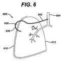
- Figure 6illustrates another exemplary collateral ventilation bypass system 600.
- the tracheais utilized to remove trapped air rather than the native airways.
- a first conduit 602extends from the patient's trachea 604, or other proximal airways, including the bronchus, to a position external of the patient's body.
- a second conduit 606is connected to the first conduit 602 via a fitting 608 and passes through the thoracic wall 610 and passes through the lung 612 at the site determined to have the highest degree of collateral ventilation. If more than one site is determined to have a high degree of collateral ventilation, multiple conduits may be utilized.
- the pressure in the lungsis greater than the pressure in the trachea 604; accordingly, the air in the highly collaterilized areas of the lung will travel through the first and second conduits 602, 606 to the trachea 604 and out of the patient's nose and mouth with the normally exhaled air.
- the first and second conduits 602, 606may comprise any suitable biocompatible tubing having a resistance to the various gases and other constituents contained in inhaled and exhaled air.
- the first and second conduits 602, 606comprise tubing having an inside diameter in the range from about 1.59 mm (1/16 inch) to about 12.7 mm (1/2 inch), and more preferably from about 3.18 mm (1/8 inch) to about 6.35 mm (1/4 inch).
- the connection of the first conduit 602 to the trachea 604may comprise any suitable airtight seal.
- a fluid communication link between the trachea 604 and the first conduit 602may be established in a manner identical to that established for a tracheotomy.
- an airtight sealis preferably maintained where the second conduit 606 passes through the thoracic wall 610 and into the lungs 612.
- An exemplary method for creating this airtight sealcomprises forming adhesions between the visceral pleura of the lung and the parietal pleura. This may be achieved using either chemical methods, including irritants, surgical methods, including pleurectomy or thorascopic talc pleurodesis, or radiotherapy methods, including radioactive gold or external radiation as is described in detail above.
- conduits 602, 606may be sealed to the skin at the sites by any known methods, including those described above with respect to Figures 2 through 5.
- the connection of the extrathoracic component, conduit 606,may comprise a drug, chemical, agent, or other means for preventing or substantially reducing the risk of infection.
- the fitting 608 connecting the first and second conduits 602, 606may comprise any suitable device for creating an airtight seal.
- the fitting 608may comprise any type of threaded or non-threaded union, compression fittings similar to compressor type fittings or any other suitable device for establishing an airtight seal and providing for quick release between the two ends of the fitting 608.
- This type of designwould allow easy access for periodic maintenance of the system 600, for example, cleaning the conduits 602, 606. Since the fitting 608 is external to the body, access to the inner body component of the system 600 would be easier. Essentially, access of the system 600 from outside the body would allow for maintenance and diagnosis/observation of the system 600 without subjecting the patient to additional stress and risk. It would also be less time consuming for the doctor.
- FIG. 7illustrates an alternate exemplary embodiment of the exemplary collateral ventilation bypass system 600 described above.
- the system 700comprises an externally positioned access port 708.
- a conduit 702extends from the patient's trachea 704, or other proximal airways, including the bronchus, through a suitable passageway internal to the patient's body and then passes through the lung 712 at the site determined to have the highest degree of collateral ventilation.
- the access port 708may be placed in-line with the conduit 702 such that at least a portion of the access port 708 is accessible outside of the body.
- the access port 708should allow the patient or a doctor to open the port and access the system 700 within the patient's body for maintenance and diagnosis/observation of the system 700 as described above.
- the access port 708may comprise any suitable device for providing an airtight seal when closed and easy access to the conduit 702 when open.
- the access port 708may comprise various valve arrangements and connectors for connecting other components which may be utilized for various functions. For example, oxygen may be supplied directly to the patient's lungs 712 if needed. In this instance, a valve may be needed to prevent the oxygen from bypassing the lungs 712 and go straight to the trachea 704.
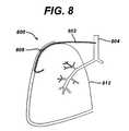
- the extrathoracic access port 708, illustrated in Figure 7may be positioned just under the skin so that it is accessible percutaneously. Essentially, the access port would not truly be extrathoracic, but rather just located under the skin and accessible extrathoracically. In this exemplary embodiment access would not be as easily accessible; however, the access point would remain more discrete than the previously described exemplary embodiments.
- Figure 8illustrates this exemplary embodiment.
- the collateral ventilation bypass system 800comprises a conduit 802 that extends from the patient's trachea 804, or other proximal airways, including the bronchus, through a suitable passageway internal to the patient's body and then passes through the lung 812 at the site determined to have the highest degree of collateral ventilation.
- a conduit 802that extends from the patient's trachea 804, or other proximal airways, including the bronchus, through a suitable passageway internal to the patient's body and then passes through the lung 812 at the site determined to have the highest degree of collateral ventilation.
- an internal access port 808may be placed in-line with the conduit 802.
- the access port 808may comprise any suitable device that allows access via percutaneous means. All remaining components may be the same as described above. In addition, all seals may be accomplished as described above.
- valvesmay be incorporated throughout the systems to prevent mucus and other substances from entering or re-entering the lung.
- the main function of the systemis to allow exhalation.
- patients with emphysemahave increased resistance to expiration and not inhalation.
- Any suitable valvesmay be utilized, for example, one-way check valves.
- Figure 9illustrates yet another alternate exemplary collateral ventilation bypass system 900.
- the trachea or other proximal airwaysincluding the bronchus, is utilized to remove air trapped in the lung or lungs.
- a conduit 902extends from the patient's bronchus 904 and passes directly into the lung 906 at the site determined to have the highest degree of collateral ventilation. If more than one site is determined to have a high degree of collateral ventilation, multiple conduits may be utilized.
- the conduit 902 in this exemplary embodimentdoes not leave the patient's body.
- the conduit 902may comprise any suitable biocompatible tubing having a resistance to the various gases and other constituents contained in inhaled and exhaled air.
- the conduit 902comprises tubing having an inside diameter in the range from about 1.59 mm (1/16 inch) to about 12.7 mm (1 ⁇ 2 inch), and more preferably in the range from about 3.18 mm (1/8 inch) to about 6.35 mm (1 ⁇ 4 inch).
- the conduit 902may comprise all of the characteristics described above.
- the conduit 902may also comprise modified ends.
- expandable features at each endmay be utilized to maintain contact and sealing between the conduit 902 and/or the bronchus 904, the trachea 908, and the lung 906 pleura.
- nitinol or other similar property materialsmay be incorporated into the conduit 902 and thus provide the conduit 902 to be delivered in a smaller diameter compressed state and then deployed in a larger diameter expanded state to help secure it in place.
- shoulders at each end of the conduit 902may also provide a mechanical stop for insertion and an area for an adhesive/sealant to join.
- the conduit 902may be introduced into the body of the patient in a number of ways, including those described herein.
- the conduit 902may be introduced utilizing an open-chest procedure, for example, a sternotomy or thoracotomy.
- the conduit 902may be introduced utilizing a laproscopic technique to make the procedure less invasive. It is important to note that the conduit 902 may be incorporated into the opening creating device. If the conduit 902 is incorporated with the opening creating device, the conduit 902 may be inserted and established in the same step as the opening creation.
- an airtight sealis preferably made between the conduit 902 and the outer pleural layer of the lung 906. This seal is maintained in order to sustain the inflation/functionality of the lungs. If the seal is breached, air can enter the pleural space and cause the lungs to collapse.
- One method for creating the sealinvolves pleuroderis or forming adhesions between the visceral pleura of the lung and the inner wall of the thoracic cavity as briefly described above and in more detail subsequently.
- a sealed joint between the conduit 902 and the outer pleural layerincludes using various glues to help with the adhesion/sealing of the conduit 902 as described above. Regardless of the procedure utilized, the seal should be established while the lung is at least partially inflated in order to maintain a solid adhesive surface. The opening may then be made after the joint has been adequately created between the conduit 902 and the lung pleural surface. The opening should be adequate in cross-sectional area in order to provide sufficient decompression of the hyperinflated lung.
- connection of the conduit 902 to the trachea or bronchus 904should also be an airtight seal.
- fluid communication between the bronchus 904 and the conduit 902may be established in a manner identical to that established for a tracheotomy.
- the conduit 902may be positioned at any suitable location within the patient's body. Preferably, the conduit 902 is positioned such that it will not affect the patient's ability to function normally.
- valves or filtersmay be incorporated into the conduit to prevent mucus and other substances from entering or re-entering the lung.
- the main function of the collateral ventilation bypass systemis to allow exhalation.
- patients with emphysemahave increased resistance to expiration and not inspiration.
- Any suitable valvesmay be utilized, for example, one-way check valves.
- the collateral ventilation bypass systems of the present inventionmay comprise one or more retention devices to prevent or substantially inhibit the migration of system components, such as conduits, into and out of the lungs and trachea.
- retention devices described hereinmay be utilized with any of the collateral ventilation bypass systems described herein or for any system in which elements are preferably held in position, for ease of explanation they will be described with respect to the exemplary embodiment illustrated in Figure 1.
- Retention devicesmay be needed to be incorporated into the design in order to prevent the components from migrating into or out of fixed positions within the lungs.
- Retention devicescould include embodiments both in the lung tissue and outside the thoracic wall, for example, on the skin.
- the retention devicemay only be required for a predetermined period of time or as a permanent implant. If the retention device is utilized as a temporary measure, it may be used after initial implantation to allow a tract to form and/or heal around the device. Once a tract is formed, any subsequent retention devices may only require an element on the skin of the patient as opposed to an additional element in the lung or lungs. However, similar to gastrostomy procedures, a device may require a chronic internal retention feature.
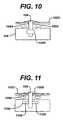
- the retention devicecomprises a balloon type retention element.
- Figure 10illustrates this exemplary balloon type retention element 1000.
- the air conduit 104( Figure 1) passes through the skin 1002, between ribs 1004 and into lung porenchymal tissue 108.
- the balloon element 1000is secured to the air carrying conduit 104 by any suitable means, including adhesive, with the balloon in a deflated state, the conduit 104 and the balloon 1000 are positioned in the lung 108 of the patient. Once all elements are in the correct position, the balloon is inflated so that the conduit cannot be removed from the patient's lung until the balloon is deflated.
- the balloon 1000may be inflated and deflated in any number of ways, including through a separate conduit positioned within the air carrying conduit 104. In an alternate exemplary embodiment, an additional balloon may be positioned outside of the lung 108 so that the air carrying conduit may not be moved in either direction.
- the balloon 1000 within the lungmay be coated with one or more agents to prevent possible damage to or reaction by the lungs.
- the retention devicecomprises a hinged structure 1100 and an external retention component 1104.
- Figure 11illustrates the exemplary embodiment.
- the air conduit 104passes through the skin 1102, between ribs 1104 and into lung parenchymal tissue 100.
- the hinged structure 1100is attached to the air carrying conduit 104 such that during insertion each flap 1106 is substantially parallel to the air carrying conduit 104 and substantially perpendicular to the air carrying conduit 104 after placement.
- the flaps 1106 of the hinged structure 1100may be controlled by spring type hinges, a separate spring structure similar to these utilized in toggle bolts or be constructed from a superelastic shape memory alloy such as nitinol.
- the flaps 1106may comprise any suitable biocompatible material and be covered with one or more agents and/or material comprising agents to prevent possible damage to or reaction by the lungs.
- a plate 1103may be positioned around and affixed to the air carrying conduit 104 outside of the lung 108.
- This plate 1108may comprise any suitable material and be attached to the skin 11102 by any suitable means, including adhesive.
- a single componentmay be utilized. With the external devices, they can be constructed such that the air carrying conduits 104 may be detached for the reasons stated above, for example, maintenance.
Landscapes
- Health & Medical Sciences (AREA)
- Pulmonology (AREA)
- Heart & Thoracic Surgery (AREA)
- Life Sciences & Earth Sciences (AREA)
- General Health & Medical Sciences (AREA)
- Biomedical Technology (AREA)
- Anesthesiology (AREA)
- Hematology (AREA)
- Engineering & Computer Science (AREA)
- Animal Behavior & Ethology (AREA)
- Public Health (AREA)
- Veterinary Medicine (AREA)
- Emergency Medicine (AREA)
- Biophysics (AREA)
- Gastroenterology & Hepatology (AREA)
- Media Introduction/Drainage Providing Device (AREA)
- External Artificial Organs (AREA)
- Pharmaceuticals Containing Other Organic And Inorganic Compounds (AREA)
- Medicines Containing Material From Animals Or Micro-Organisms (AREA)
- Infusion, Injection, And Reservoir Apparatuses (AREA)
- Respiratory Apparatuses And Protective Means (AREA)
Abstract
Description
- The present invention relates to systems and methods for treating diseased lungs, and more particularly, to devices and methods for removing trapped air in the lungs.
- As a result of studies that date back to the 1930's and particularly studies conducted in the 1960's and early 1970's, it has been determined that long-term continuous oxygen therapy is beneficial in the treatment of hypoxemic patients with chronic obstructive pulmonary disease. In other words, a patient's life and quality of life can be improved by providing a constant supplemental supply of oxygen to the patient's lungs.
- However, with the desire to contain medical costs, there is a growing concern that the additional cost of providing continuous oxygen therapy for chronic lung disease will create an excessive increase in the annual cost of oxygen therapy. Thus, it is desirable that oxygen therapy, when provided, be as cost effective as possible.
- The standard treatment for patients requiring supplemental oxygen is still to deliver oxygen from an oxygen source by means of a nasal cannula. Such treatment, however, requires a large amount of oxygen, which is wasteful and can cause soreness and irritation to the nose, as well as being potentially aggravating. Other undesirable effects have also been reported. Various other medical approaches, which have been proposed to help reduce the cost of continuous oxygen therapy, have been studied.
- Various devices and methods have been devised for performing emergency cricothyroidotomies and for providing a tracheotomy tube so that a patient whose airway is otherwise blocked may continue to breath. Such devices are generally intended only for use with a patient who is not breathing spontaneously and are not suitable for the long term treatment of chronic lung disease. Typically, such devices are installed by puncturing the skin to create a hole into the cricoid membrane of the larynx above the trachea into which a relatively large curved tracheotomy tube is inserted. As previously described, the use of such tubes has been restricted medically to emergency situations where the patient would otherwise suffocate due to the blockage of the airway. Such emergency tracheotomy tubes are not suitable for long term therapy after the airway blockage is removed.
- Other devices which have been found satisfactory for emergency or ventilator use are described in
US-953,922 to Rogers ;US-2,873,742 to Shelden ;US-3,384,087 to Brummelkamp ;US-3,511,243 to Toy ;US-3,556,103 to Calhoun ;US-2,991,787 to Shelden, et al ;US-3,688,773 to Weiss ;US-3,817,250 to Weiss, et al. ; andUS-3,916,903 to Pozzi . - Although tracheotomy tubes are satisfactory for their intended purpose, they are not intended for chronic usage by outpatients as a means for delivering supplemental oxygen to spontaneously breathing patients with chronic obstructive pulmonary disease. Such tracheotomy tubes are generally designed so as to provide the total air supply to the patient for a relatively short period of time. The tracheotomy tubes are generally of rigid or semi-rigid construction and of caliber ranging from 2.5 mm outside diameter in infants to 15 mm outside diameter in adults. They are normally inserted in an operating room as a surgical procedure or during emergency situations, through the crico-thyroid membrane where the tissue is less vascular and the possibility of bleeding is reduced. These devices are intended to permit passage of air in both directions until normal breathing has been restored by other means.
- Another type of tracheotomy tube is disclosed in Jacobs,
US-3,682,166 andUS-3,788,326 . The catheter described therein is placed over 14 or 16-gauge needle and inserted through the crico-thyroid membrane for supplying air or oxygen and vacuum on an emergency basis to restore the breathing of a non-breathing patient. The air or oxygen is supplied at 30 to 100 psi for inflation and deflation of the patient's lungs. The Jacobs catheter, like the other tracheotomy tubes previously used, is not suitable for long-term outpatient use, and could not easily be adapted to such use. - Due to the limited functionality of tracheotomy tubes, transtracheal catheters have been proposed and used for long term supplemental oxygen therapy. For example the small diameter transtracheal catheter (16 gauge) developed by Dr. Henry J. Heimlich (described inTHE ANNALS OF OTOLOGY, RHINOLOGY & LARYNGOLOGY, November-December 1982; Respiratory Rehabilitation with Transtracheal Oxygen System) has been used by the insertion of a relatively large cutting needle (14 gauge) into the trachea at the mid-point between the cricothyroid membrane and the sternal notch. This catheter size can supply oxygen up to about 3 liters per minute at low pressures, such as 2 psi which may be insufficient for patients who require higher flow rates. It does not, however, lend itself to outpatient use and maintenance, such as periodic removal and cleaning, primarily because the connector between the catheter and the oxygen supply hose is adjacent and against the anterior portion of the trachea and cannot be easily seen and manipulated by the patient. Furthermore, the catheter is not provided with positive means to protect against kinking or collapsing which would prevent its effective use on an outpatient basis. Such a feature is not only desirable but necessary for long term outpatient and home care use. Also, because of its structure, i.e. only one exit opening, the oxygen from the catheter is directed straight down the trachea toward the bifurcation between the bronchi. Because of the normal anatomy of the bronchi wherein the left bronchus is at a more acute angle to the trachea than the right bronchus, more of the oxygen from that catheter tends to be directed into the right bronchus rather than being directed or mixed for more equal utilization by both bronchi. Also, as structured, the oxygen can strike the carina, resulting in an undesirable tickling sensation and cough. In addition, in such devices, if a substantial portion of the oxygen is directed against the back wall of the trachea causing erosion of the mucosa in this area which may cause chapping and bleeding. Overall, because of the limited output from the device, it may not operate to supply sufficient supplemental oxygen when the patient is exercising or otherwise quite active or has severe disease.
- Diseases associated with chronic obstructive pulmonary disease include chronic bronchitis and emphysema. One aspect of an emphysematous lung is that the communicating flow of air between neighboring air sacs is much more prevalent as compared to healthy lungs. This phenomenon is known as collateral ventilation. Another aspect of an emphysematous lung is that air cannot be expelled from the native airways due to the loss of tissue elastic recoil and radial support of the airways. Essentially, the loss of elastic recoil of the lung tissue contributes to the inability of individuals to exhale completely. The loss of radial support of the airways also allows a collapsing phenomenon to occur during the expiratory phase of breathing. This collapsing phenomenon also intensifies the inability for individuals to exhale completely. As the inability to exhale completely increases, residual volume in the lungs also increases. This then causes the lung to establish in a hyperinflated state where an individual can only take short shallow breaths. Essentially, air is not effectively expelled and stale air accumulates in the lungs. Once the stale air accumulates in the lungs, the individual is deprived of oxygen.
- Currently, treatments for chronic obstructive pulmonary disease include bronchodilating drugs, oxygen therapy as described above, and lung volume reduction surgery. Bronchodilating drugs only work on a percentage of patients with chronic obstructive pulmonary disease and generally only provides short-term relief. Oxygen therapy is impractical for the reasons described above, and lung volume reduction surgery is an extremely traumatic procedure that involves removing part of the lung. The long term benefits of lung volume reduction surgery are not fully known.
- Accordingly, there exists a need for safely and effectively removing trapped air from a diseased lung or lungs.
- The present invention overcomes the limitations in treating diseases associated with chronic obstructive pulmonary disorders as briefly described above.
- In accordance with one aspect, the present invention comprises a collateral ventilation bypass system comprising at least one conduit extending into at least one lung at a predetermined location for removing trapped gases from the at least one lung and a fixation device operatively associated with the at least one conduit positioned inside the at least one lung to substantially prevent unnecessary movement of the at least one conduit.
- The collateral ventilation bypass trap system of the present invention utilizes the above-described collateral ventilation phenomenon to increase the expiratory flow from a diseased lung or lungs, thereby treating another aspect of chronic obstructive pulmonary disease. Essentially, the most collaterally ventilated area of the lung or lungs is determined utilizing the scanning techniques described above. Once this area or areas are located, a conduit or conduits are positioned in a passage or passages that access the outer pleural layer of the diseased lung or lungs. The conduit or conduits utilize the collateral ventilation of the lung or lungs and allow the entrapped air to bypass the native airways and be expelled to a containment system outside of the body.
- In an alternate embodiment, the trachea, or other proximal airways, including the bronchus, may be utilized for expelling trapped air rather than a containment/trap device.
- Retention devices may be utilized to secure the various components of the collateral ventilation bypass trap system in position. The retention devices may take one or a maximum of configurations.
- Air typically enters the mammalian body through the nostrils and flows into the nasal cavities. As the air passes through the nostrils and nasal cavities, it is filtered, moistened and raised or lowered to approximately body temperature. The back of the nasal cavities is continuous with the pharynx (throat region); therefore, air may reach the pharynx from the nasal cavities or from the mouth. Accordingly, if equipped, the mammal may breath through its nose or mouth. Generally air from the mouth is not as filtered or temperature regulated as air from the nostrils. The air in the pharynx flows from an opening in the floor of the pharynx and into the larynx (voice box). The epiglottis automatically closes off the larynx during swallowing so that solids and/or liquids enter the esophagus rather than the lower air passageways or airways. From the larynx, the air passes into the trachea, which divides into two branches, referred to as the bronchi. The bronchi are connected to the lungs.
- The lungs are large, paired, spongy, elastic organs, which are positioned in the thoracic cavity. The lungs are in contact with the walls of the thoracic cavity. In humans, the right lung comprises three lobes and the left lung comprises two lobes. Lungs are paired in, all mammals, but the number of lobes or sections of lungs varies from mammal to mammal. Healthy lungs, as discussed below, have a tremendous surface area for gas/air exchange. Both the left and right lung is covered with a pleural membrane. Essentially, the pleural membrane around each lung forms a continuous sac that encloses the lung. A pleural membrane also forms a lining for the thoracic cavity. The space between the pleural membrane forming the lining of the thoracic cavity and the pleural membranes enclosing the lungs is referred to as the pleural cavity. The pleural cavity comprises a film of fluid that serves as a lubricant between the lungs and the chest wall.
- In the lungs, the bronchi branch into a multiplicity of smaller vessels referred to as bronchioles. Typically, there are more than one million bronchioles in each lung. Each bronchiole ends in a cluster of extremely small air sacs referred to as alveoli. An extremely thin, single layer of epithelial cells lining each alveolus wall and an extremely thin, single layer of epithelial cells lining the capillary walls separate the air/gas in the alveolus from the blood. Oxygen molecules in higher concentration pass by simple diffusion through the two thin layers from the alveoli into the blood in the pulmonary capillaries. Simultaneously, carbon dioxide molecules in higher concentration pass by simple diffusion through the two thin layers from the blood in the pulmonary capillaries into the alveoli.
- Breathing is a mechanical process involving inspiration and expiration. The thoracic cavity is normally a closed system and air cannot enter or leave the lungs except through the trachea. If the chest wall is somehow compromised and air/gas enters the pleural cavity, the lungs will typically collapse. When the volume of the thoracic cavity is increased by the contraction of the diaphragm, the volume of the lungs is also increased. As the volume of the lungs increase, the pressure of the air in the lungs falls slightly below the pressure of the air external to the body (ambient air pressure). Accordingly, as a result of this slight pressure differential, external or ambient air flows through the respiratory passageways described above and fills the lungs until the pressure equalizes. This process is inspiration. When the diaphragm is relaxed, the volume of the thoracic cavity decreases, which in turn decreases the volume of the lungs. As the volume of the lungs decrease, the pressure of the air in the lungs rises slightly above the pressure of the air external to the body. Accordingly, as a result of this slight pressure differential, the air in the alveoli is expelled through the respiratory passageways until the pressure equalizes. This process is expiration.
- Continued insult to the respiratory system may result in various diseases, for example, chronic obstructive pulmonary disease. Chronic obstructive pulmonary disease is a persistent obstruction of the airways caused by chronic bronchitis and pulmonary emphysema. In the United States alone, approximately fourteen million people suffer from some form of chronic obstructive pulmonary disease and it is in the top ten leading causes of death.
- Chronic bronchitis and acute bronchitis share certain similar characteristics; however, they are distinct diseases. Both chronic and acute bronchitis involve inflammation and constriction of the bronchial tubes and the bronchioles; however, acute bronchitis is generally associated with a viral and/or bacterial infection and its duration is typically much shorter than chronic bronchitis. In chronic bronchitis, the bronchial tubes secrete too much mucus as part of the body's defensive mechanisms to inhaled foreign substances. Mucus membranes comprising ciliated cells (hair like structures) line the trachea and bronchi. The ciliated cells or cilia continuously push or sweep the mucus secreted from the mucus membranes in a direction away from the lungs and into the pharynx where it is periodically swallowed. This sweeping action of the cilia functions to keep foreign matter from reaching the lungs. Foreign matter that is not filtered by the nose and larynx, as described above, becomes trapped in the mucus and is propelled by the cilia into the pharynx. When too much mucus is secreted, the ciliated cells may become damaged, leading to a decrease in the efficiency of the cilia to sweep the bronchial tubes and trachea of the mucus containing the foreign matter. This in turn causes the bronchioles to become constricted and inflamed and the individual becomes short of breath. In addition, the individual will develop a chronic cough as a means of attempting to clear the airways of excess mucus.
- Individuals who suffer from chronic bronchitis may develop pulmonary emphysema. Pulmonary emphysema is a disease in which the alveoli walls, which are normally fairly rigid structures, are destroyed. The destruction of the alveoli walls is irreversible. Pulmonary emphysema may be caused by a number of factors, including chronic bronchitis, long term exposure to inhaled irritants, e.g. air pollution, which damage the cilia, enzyme deficiencies and other pathological conditions. In pulmonary emphysema, the alveoli of the lungs lose their elasticity, and eventually the walls between adjacent alveoli are destroyed. Accordingly, as more and more alveoli walls are lost, the air exchange (oxygen and carbon dioxide) surface area of the lungs is reduced until air exchange becomes seriously impaired. The combination of mucus hypersecretion (described above) and dynamic airway compression are mechanisms of airflow limitation in chronic obstructive pulmonary disease. Dynamic airway compression results from the loss of tethering forces exerted on the airway due to the reduction in lung tissue elasticity. In other words, the breakdown of lung tissue leads to the reduced ability of the lungs to recoil and the loss of radial support of the airways. Consequently, the loss of elastic recoil of the lung tissue contributes to the inability of individuals to exhale completely. The loss of radial support of the airways also allows a collapsing phenomenon to occur during the expiratory phase of breathing. This collapsing phenomenon also intensifies the inability for individuals to exhale completely. As the inability to exhale completely increases, residual volume in the lungs also increases. This then causes the lung to establish in a hyperinflated state where an individual can only take short shallow breaths. Essentially, air is not effectively expelled and stale air accumulates in the lungs. Once the stale air accumulates in the lungs, the individual is deprived of oxygen. There is no cure for pulmonary emphysema, only various treatments, including exercise, drug therapy, such as bronchodilating agents, lung volume reduction surgery and long term oxygen therapy.
- In emphysema, alveoli walls are destroyed, thereby causing a decrease in air exchange surface area. As more alveoli walls are destroyed, collateral ventilation resistance is lowered. In other words, pulmonary emphysema causes an increase in collateral ventilation and to a certain extent, chronic bronchitis also causes an increase in collateral ventilation. Essentially, in an emphysematous lung, the communicating flow of air between neighboring air sacs (alveoli), known as collateral ventilation, is much more prevalent as compared to a normal lung. Since air cannot be expelled from the native airways due to the loss of tissue elastic recoil and radial support of the airways (dynamic collapse during exhalation), the increase in collateral ventilation does not significantly assist an individual in breathing. The individual develops dsypnea. Accordingly, if it can be determined where collateral ventilation is occurring, then the diseased lung tissue may be directly treated. Various methods may be utilized to determine the diseased tissue locations, for example, computerized axial tomography or CAT scans, magnetic resonance imaging or MRI, positron emission tomograph or PET, and/or standard X-ray imaging.
- As set forth above, emphysema is distinguished as irreversible damage to lung tissue. The breakdown of lung tissue leads to the reduced ability for the lungs to recoil. The tissue breakdown also leads to the loss of radial support of the native airways. Consequently, the loss of elastic recoil of the lung tissue contributes to the inability for individuals with emphysema to exhale completely. The loss of radial support of the native airways also allows a collapsing phenomenon to occur during the expiratory phase of breathing. This collapsing phenomenon also intensifies the inability for individuals to exhale completely. As the inability to exhale increases, residual volume in the lungs also increases. This then causes the lung to establish in a hyperinflated state wherein an individual can only take short shallow breaths.
- The collateral ventilation bypass trap system of the present invention utilizes the above-described collateral ventilation phenomenon to increase the expiratory flow from a diseased lung or lungs, thereby treating another aspect of chronic obstructive pulmonary disease. Essentially, the most collaterally ventilated area of the lung or lungs is determined utilizing the scanning techniques described above. Once this area or areas are located, a conduit or conduits are positioned in a passage or passages that access the outer pleural layer of the diseased lung or lungs. The conduit or conduits utilize the collateral ventilation of the lung or lungs and allows the entrapped air to bypass the native airways and be expelled to a containment system outside of the body.
- Embodiments of the invention will now be described by way of example with reference to the accompanying drawings, in which:
- Figure 1 is a diagrammatic representation of a first exemplary embodiment of a collateral ventilation bypass trap system in accordance with the present invention.
- Figure 2 is a diagrammatic representation of a first exemplary embodiment of a sealing device utilized in conjunction with the long term oxygen therapy system of the present invention.
- Figure 3 is a diagrammatic representation of a second exemplary embodiment of a sealing device utilized in conjunction with the long term oxygen therapy system of the present invention.
- Figure 4 is a diagrammatic representation of a third exemplary embodiment of a sealing device utilized in conjunction with the long term oxygen therapy system of the present invention.
- Figure 5 is a diagrammatic representation of a fourth exemplary embodiment of a sealing device utilized in conjunction with the long term oxygen therapy system of the present invention.
- Figure 6 is a diagrammatic representation of a second exemplary embodiment of a collateral ventilation bypass system in accordance with the present invention.
- Figure 7 is a diagrammatic representation of a third exemplary embodiment of a collateral ventilation bypass system in accordance with the present invention.
- Figure 8 is a diagrammatic representation of a fourth exemplary embodiment of a collateral ventilation bypass system in accordance with the present invention.
- Figure 9 is a diagrammatic representation of an exemplary embodiment of an intra-thoracic collateral ventilation bypass system in accordance with the present invention.
- Figure 10 is a diagrammatic representation of a first exemplary embodiment of a retention device in accordance with the present invention.
- Figure 11 is a diagrammatic representation of a second exemplary embodiment of a retention device in accordance with the present invention.
- Figure 1 illustrates a first exemplary collateral ventilation
bypass trap system 100. Thesystem 100 comprises atrap 102, anair carrying conduit 104 and a filter/one-way valve 106. Theair carrying conduit 104 creates a fluid communication link between an individual'slung 108 and thetrap 102 through the filter/one-way valve 106. It is important to note that although asingle conduit 104 is illustrated, multiple conduits may be utilized in eachlung 108 if it is determined that there is more than one area of high collateral ventilation. - The
trap 102 may comprise any suitable device for collecting discharge from the individual's lung orlungs 108. Essentially, thetrap 102 is simply a containment vessel for temporarily storing discharge from the lungs, for example, mucous and other fluids that may accumulate in the lungs. Thetrap 102 may comprise any suitable shape and may be formed from any suitable metallic or non-metallic materials. Preferably, thetrap 102 should be formed from a lightweight, non-corrosive material. In addition, thetrap 102 should be designed in such a manner as to allow for effective and efficient cleaning. In one exemplary embodiment, thetrap 102 may comprise disposable liners that may be removed when thetrap 102 is full. Thetrap 102 may be formed from a transparent material or comprise an indicator window so that it may be easily determined when thetrap 102 should be emptied or cleaned. Alightweight trap 102 increases the patient's mobility. - The filter/one-
way valve 106 may be attached to thetrap 102 by any suitable means, including threaded fittings or compression type fittings commonly utilized in compressor connections. The filter/one-way valve 106 serves a number of functions. The filter/one-way valve 106 allows the air from the individual's lung orlungs 108 to exit thetrap 102 while maintaining the fluid discharge and solid particulate matter in thetrap 102. This filter/one-way valve 106 would essentially maintain the pressure in thetrap 102 below that of the pressure inside the individual's lung orlungs 108 so that the flow of air from thelungs 108 to thetrap 102 is maintained in this one direction. The filter portion of the filter/one-way valve 106 may be designed to capture particulate matter of a particular size which is suspended in the air, but allows the clean air to pass therethrough and be vented to the ambient environment. The filter portion may also be designed in such a manner as to reduce the moisture content of the exhaled air. - The
air carrying conduit 104 connects thetrap 102 to the lung orlungs 108 of the patient through the filter/one-way valve 106. Theair carrying conduit 104 may comprise any suitable biocompatible tubing having a resistance to the gases contained in air. Theair carrying conduit 104 comprises tubing having an inside diameter in the range from about 1.59 mm (1/16 inch) to about 12.7 mm (1/2 inch), and more preferably from about 3.18 mm (1/8 inch) to about 6.35 mm (1/4 inch). The filter/one-way valve 106 may comprise any suitable valve which allows air to flow from the lung orlungs 108 through theair carrying conduit 104, but not from thetrap 102 back to thelungs 108. For example, a simple check valve may be utilized. Theair carrying conduit 104 may be connected to the filter/one-way valve 106 by any suitable means. Preferably, a quick release mechanism is utilized so that the trap may be easily removed for maintenance. - As illustrated in Figure 1, the
air carrying conduit 104 passes through thelung 108 at the site determined to have the highest degree of collateral ventilation. If more than one site is determined, multipleair carrying conduits 104 may be utilized. The connection of multipleair carrying conduits 104 to the filter/one-way valve 106 may be accomplished by any suitable means, including an octopus device similar to that utilized in scuba diving regulators. - The
air carrying conduit 104 is preferably able to withstand and resist collapsing once in place. Since air will travel through theconduit 104, if the conduit is crushed and unable to recover, the effectiveness of the system is diminished. Accordingly, a crush recoverable material may be incorporated into theair carrying conduit 104 in order to make it crush recoverable. Any number of suitable materials may be utilized. For example, Nitinol incorporated into theconduit 104 will give the conduit collapse resistance and collapse recovery properties. In this type of exemplary embodiment, nitinol wire may be embedded in theconduit 104 and treated or programmed to maintain an expanded diameter. In other words, theconduit 104 may comprise a polymeric coating over a suitably arranged nitinol base structure. The polymeric coating or cover layer may be formed from any available biocompatible polymeric materials, including polytetrafleurethelene, silicone and polyurethanes. - Expandable features at the end of the
conduit 104 may be used to aid in maintaining contact and sealing theconduit 104 to the lung pleura. Nitinol incorporated into theconduit 104 will provide the ability to deliver theconduit 104 in a compressed state and then deployed in an expanded state to secure it in place. Shoulders at the end of the conduit may also provide a mechanical stop for insertion and an area for an adhesive/sealant to join as described in detail subsequently. - In order for the exemplary collateral ventilation
bypass trap system 100 to function, an airtight seal is preferably maintained where theair carrying conduit 104 passes through the thoracic cavity andlungs 108. This seal is maintained in order to sustain the inflation/functionality of the lungs. If the seal is breached, air may enter the cavity and cause the lungs to collapse. One exemplary method for creating the seal comprises forming adhesions between the visceral pleura of the lung and the inner wall of the thoracic cavity. This may be achieved using either chemical methods, including irritants such as Doxycycline and/or Bleomycin, surgical methods, including pleurectomy or thorascopic talc pleurodesis, or radiotherapy methods, including radioactive gold or external radiation. All of these methods are known in the relevant art for creating pleurodesis. In another alternate exemplary embodiment, a sealed joint between theair carrying conduit 104 and the outer pleural layer includes using various glues to help with the adhesion/sealing of theair carrying conduit 104. Currently, Focal Inc. markets a sealant available under the tradename Focal/Seal-L which is indicated for use on a lung for sealing purposes. Focal/Seal-L is activated by light in order to cure the sealant. Another seal available under the tradename Thorex, which is manufactured by Surgical Sealants Inc., is currently conducting a clinical trial for lung sealing indications. Thorex is a two-part sealant that has a set curing time after the two parts are mixed. - The creation of the opening in the chest cavity may be accomplished in a number of ways. For example, the procedure may be accomplished using an open chest procedure, aternotomy or thoracotomy. Alternately, the procedure may be accomplished using a laproscopic technique, which is less invasive. Regardless of the procedure utilized, the seal should be established while the lung is at least partially inflated in order to maintain a solid adhesive surface. The opening may then be made after the joint has been adequately created between the conduit component and the lung pleural surface. The opening should be adequate in cross-sectional area in order to provide sufficient decompression of the hyperinflated lung. This opening, as stated above, may be created using a number of different techniques such as cutting, piercing, dilating, blunt dissection, radio frequency energy, ultrasonic energy, microwave energy, or cryoblative energy.
- The
air carrying conduit 104 may be sealed to the skin by any suitable means. Similarly to ostomy pouches or bags, theair carrying conduit 104 may be sealed to the skin at the site of the ventilation bypass. In one exemplary embodiment as illustrated in Figure 2, theair carrying conduit 104 may be sealed to the skin of the thoracic wall utilizing an adhesive. As illustrated, theair carrying conduit 104 comprises aflange 200 having a biocompatible adhesive coating on the skin contacting surface. The biocompatible adhesive would provide a fluid tight seal between theflange 200 and the skin or epidermis of the thoracic wall. In a preferred embodiment, the biocompatible adhesive provides a temporary fluid tight seal such that theair carrying conduit 104 may be disconnected from the ventilation bypass site. This would allow for the site to be cleaned and for the collateralventilation bypass system 100 to undergo periodic maintenance. - Figure 3 illustrates another exemplary embodiment for sealing the
air carrying conduit 104 to the skin of the thoracic wall at the site of the ventilation bypass. In this exemplary embodiment, acoupling plate 300 is sealed to the skin at the site of the ventilation bypass by a biocompatible adhesive coating or any other suitable means. Theair carrying conduit 104 is then connected to thecoupling plate 300 by any suitable means, including threaded couplings and locking rings. The exemplary embodiment also allows for cleaning of the site and maintenance of thesystem 100. - Figure 4 illustrates yet another exemplary embodiment for sealing the
air carrying conduit 104 to the skin of the thoracic wall at the site of the ventilation bypass. In this exemplary embodiment,balloon flanges 400 may be utilized to create the seal. Theballoon flanges 400 may be attached to theair carrying conduit 104 such that in the deflated state, theair carrying conduit 104 and one of the balloon flanges passes through the ventilation bypass anastomosis. Theballoon flanges 400 are spaced apart a sufficient distance such that the balloon flanges remain on opposite sides of the thoracic wall. When inflated, the balloons expand and form a fluid tight seal by sandwiching the thoracic wall. Once again, this exemplary embodiment allows for easy removal of theair carrying conduit 104. - Figure 5 illustrates yet another exemplary embodiment for sealing the
air carrying conduit 104 to the skin of the thoracic wall at the site of the ventilation bypass. In this exemplary embodiment, asingle balloon flange 500 is utilized in combination with a fixedflange 502. Theballoon flange 500 is connected to theair carrying conduit 104 in the same manner as described above. In this exemplary embodiment, theballoon flange 500, when inflated, forms the fluid tight seal. The fixedflange 502, which is maintained against the skin of the thoracic wall, provides the structural support against which the balloon exerts pressure to form the seal. - In operation, when an individual exhales, the pressure in the lungs is greater than the pressure in the
trap 102. Accordingly, the air in the highly collaterilized areas of the lung will travel through theair carrying conduit 104 to thetrap 102. This operation will allow the individual to more easily and completely exhale. - Figure 6 illustrates another exemplary collateral
ventilation bypass system 600. In this exemplary embodiment, the trachea is utilized to remove trapped air rather than the native airways. As illustrated, afirst conduit 602 extends from the patient'strachea 604, or other proximal airways, including the bronchus, to a position external of the patient's body. Asecond conduit 606 is connected to thefirst conduit 602 via a fitting 608 and passes through thethoracic wall 610 and passes through thelung 612 at the site determined to have the highest degree of collateral ventilation. If more than one site is determined to have a high degree of collateral ventilation, multiple conduits may be utilized. In operation, when the patient exhales, the pressure in the lungs is greater than the pressure in thetrachea 604; accordingly, the air in the highly collaterilized areas of the lung will travel through the first andsecond conduits trachea 604 and out of the patient's nose and mouth with the normally exhaled air. - The first and
second conduits second conduits - The connection of the
first conduit 602 to thetrachea 604 may comprise any suitable airtight seal. For example, a fluid communication link between thetrachea 604 and thefirst conduit 602 may be established in a manner identical to that established for a tracheotomy. In addition, as stated above, in order for the collateralventilation bypass system 600 to function, an airtight seal is preferably maintained where thesecond conduit 606 passes through thethoracic wall 610 and into thelungs 612. An exemplary method for creating this airtight seal comprises forming adhesions between the visceral pleura of the lung and the parietal pleura. This may be achieved using either chemical methods, including irritants, surgical methods, including pleurectomy or thorascopic talc pleurodesis, or radiotherapy methods, including radioactive gold or external radiation as is described in detail above. - The
conduits conduit 606, may comprise a drug, chemical, agent, or other means for preventing or substantially reducing the risk of infection. - The fitting 608 connecting the first and
second conduits system 600, for example, cleaning theconduits system 600 would be easier. Essentially, access of thesystem 600 from outside the body would allow for maintenance and diagnosis/observation of thesystem 600 without subjecting the patient to additional stress and risk. It would also be less time consuming for the doctor. - Figure 7 illustrates an alternate exemplary embodiment of the exemplary collateral
ventilation bypass system 600 described above. In this exemplary embodiment, thesystem 700 comprises an externally positionedaccess port 708. As illustrated, aconduit 702 extends from the patient'strachea 704, or other proximal airways, including the bronchus, through a suitable passageway internal to the patient's body and then passes through thelung 712 at the site determined to have the highest degree of collateral ventilation. As set forth above, if more than one site is determined to have a high degree of collateral ventilation, multiple conduits may be utilized. At the desired location within the body, theaccess port 708 may be placed in-line with theconduit 702 such that at least a portion of theaccess port 708 is accessible outside of the body. Essentially, theaccess port 708 should allow the patient or a doctor to open the port and access thesystem 700 within the patient's body for maintenance and diagnosis/observation of thesystem 700 as described above. - The
access port 708 may comprise any suitable device for providing an airtight seal when closed and easy access to theconduit 702 when open. Theaccess port 708 may comprise various valve arrangements and connectors for connecting other components which may be utilized for various functions. For example, oxygen may be supplied directly to the patient'slungs 712 if needed. In this instance, a valve may be needed to prevent the oxygen from bypassing thelungs 712 and go straight to thetrachea 704. - All the remaining components may be the same as described above. In addition, all seals may be accomplished as described above.
- In yet another alternate exemplary embodiment, the
extrathoracic access port 708, illustrated in Figure 7, may be positioned just under the skin so that it is accessible percutaneously. Essentially, the access port would not truly be extrathoracic, but rather just located under the skin and accessible extrathoracically. In this exemplary embodiment access would not be as easily accessible; however, the access point would remain more discrete than the previously described exemplary embodiments. Figure 8 illustrates this exemplary embodiment. - As illustrated in Figure 8, the collateral
ventilation bypass system 800 comprises aconduit 802 that extends from the patient'strachea 804, or other proximal airways, including the bronchus, through a suitable passageway internal to the patient's body and then passes through thelung 812 at the site determined to have the highest degree of collateral ventilation. As set forth above, if more than one site is determined to have a high degree of collateral ventilation, multiple conduits may be utilized. At the desired location within the body, aninternal access port 808 may be placed in-line with theconduit 802. Theaccess port 808 may comprise any suitable device that allows access via percutaneous means. All remaining components may be the same as described above. In addition, all seals may be accomplished as described above. - It is important to note that in each of the above-described exemplary embodiments, additional components may be added that function to prevent flow from the trachea end of the conduit to the lung. For example, one or more valves may be incorporated throughout the systems to prevent mucus and other substances from entering or re-entering the lung. The main function of the system is to allow exhalation. In theory, patients with emphysema have increased resistance to expiration and not inhalation. Any suitable valves may be utilized, for example, one-way check valves.
- Figure 9 illustrates yet another alternate exemplary collateral
ventilation bypass system 900. In this exemplary embodiment, like the exemplary embodiments illustrated in Figures 6-8, the trachea or other proximal airways, including the bronchus, is utilized to remove air trapped in the lung or lungs. As illustrated, aconduit 902 extends from the patient'sbronchus 904 and passes directly into thelung 906 at the site determined to have the highest degree of collateral ventilation. If more than one site is determined to have a high degree of collateral ventilation, multiple conduits may be utilized. In operation, when the patient exhales, the pressure in the lungs is greater than the pressure in thebronchus 904; accordingly, the air in the highly collateralized area or areas of the lung will travel through theconduit 902 to thebronchus 904, into thetrachea 908 and out of the patient's nose and mouth, not shown, with the normally exhaled air. - The
conduit 902 in this exemplary embodiment does not leave the patient's body. Theconduit 902 may comprise any suitable biocompatible tubing having a resistance to the various gases and other constituents contained in inhaled and exhaled air. As in previously described exemplary embodiments, theconduit 902 comprises tubing having an inside diameter in the range from about 1.59 mm (1/16 inch) to about 12.7 mm (½ inch), and more preferably in the range from about 3.18 mm (1/8 inch) to about 6.35 mm (¼ inch). In addition, theconduit 902 may comprise all of the characteristics described above. - The
conduit 902 may also comprise modified ends. For example, expandable features at each end may be utilized to maintain contact and sealing between theconduit 902 and/or thebronchus 904, thetrachea 908, and thelung 906 pleura. Once again, nitinol or other similar property materials may be incorporated into theconduit 902 and thus provide theconduit 902 to be delivered in a smaller diameter compressed state and then deployed in a larger diameter expanded state to help secure it in place. Alternately, shoulders at each end of theconduit 902 may also provide a mechanical stop for insertion and an area for an adhesive/sealant to join. - The
conduit 902 may be introduced into the body of the patient in a number of ways, including those described herein. In one exemplary embodiment, theconduit 902 may be introduced utilizing an open-chest procedure, for example, a sternotomy or thoracotomy. In al alternate exemplary embodiment, theconduit 902 may be introduced utilizing a laproscopic technique to make the procedure less invasive. It is important to note that theconduit 902 may be incorporated into the opening creating device. If theconduit 902 is incorporated with the opening creating device, theconduit 902 may be inserted and established in the same step as the opening creation. - As stated in the above-described exemplary embodiments, in order for the collateral
ventilation bypass system 900 to function, an airtight seal is preferably made between theconduit 902 and the outer pleural layer of thelung 906. This seal is maintained in order to sustain the inflation/functionality of the lungs. If the seal is breached, air can enter the pleural space and cause the lungs to collapse. One method for creating the seal involves pleuroderis or forming adhesions between the visceral pleura of the lung and the inner wall of the thoracic cavity as briefly described above and in more detail subsequently. In another alternate exemplary embodiment, a sealed joint between theconduit 902 and the outer pleural layer includes using various glues to help with the adhesion/sealing of theconduit 902 as described above. Regardless of the procedure utilized, the seal should be established while the lung is at least partially inflated in order to maintain a solid adhesive surface. The opening may then be made after the joint has been adequately created between theconduit 902 and the lung pleural surface. The opening should be adequate in cross-sectional area in order to provide sufficient decompression of the hyperinflated lung. - The connection of the
conduit 902 to the trachea orbronchus 904 should also be an airtight seal. For example, fluid communication between thebronchus 904 and theconduit 902 may be established in a manner identical to that established for a tracheotomy. - The
conduit 902 may be positioned at any suitable location within the patient's body. Preferably, theconduit 902 is positioned such that it will not affect the patient's ability to function normally. - It is important to note that in the above-described exemplary embodiment, additional components may be added that function to prevent flow from the bronchus to the lung. For example, one or more valves or filters may be incorporated into the conduit to prevent mucus and other substances from entering or re-entering the lung. The main function of the collateral ventilation bypass system is to allow exhalation. In theory, patients with emphysema have increased resistance to expiration and not inspiration. Any suitable valves may be utilized, for example, one-way check valves.
- In accordance with another exemplary embodiment, the collateral ventilation bypass systems of the present invention may comprise one or more retention devices to prevent or substantially inhibit the migration of system components, such as conduits, into and out of the lungs and trachea. Although the retention devices described herein may be utilized with any of the collateral ventilation bypass systems described herein or for any system in which elements are preferably held in position, for ease of explanation they will be described with respect to the exemplary embodiment illustrated in Figure 1.
- Essentially, if a system having one or more components is positioned so that it accesses the lung or lungs through the thoracic wall, devices may be needed to be incorporated into the design in order to prevent the components from migrating into or out of fixed positions within the lungs. Retention devices could include embodiments both in the lung tissue and outside the thoracic wall, for example, on the skin. The retention device may only be required for a predetermined period of time or as a permanent implant. If the retention device is utilized as a temporary measure, it may be used after initial implantation to allow a tract to form and/or heal around the device. Once a tract is formed, any subsequent retention devices may only require an element on the skin of the patient as opposed to an additional element in the lung or lungs. However, similar to gastrostomy procedures, a device may require a chronic internal retention feature.
- In accordance with once exemplary embodiment, the retention device comprises a balloon type retention element. Figure 10 illustrates this exemplary balloon
type retention element 1000. As illustrated, the air conduit 104 (Figure 1) passes through theskin 1002, betweenribs 1004 and intolung porenchymal tissue 108. Theballoon element 1000 is secured to theair carrying conduit 104 by any suitable means, including adhesive, with the balloon in a deflated state, theconduit 104 and theballoon 1000 are positioned in thelung 108 of the patient. Once all elements are in the correct position, the balloon is inflated so that the conduit cannot be removed from the patient's lung until the balloon is deflated. Theballoon 1000 may be inflated and deflated in any number of ways, including through a separate conduit positioned within theair carrying conduit 104. In an alternate exemplary embodiment, an additional balloon may be positioned outside of thelung 108 so that the air carrying conduit may not be moved in either direction. Theballoon 1000 within the lung may be coated with one or more agents to prevent possible damage to or reaction by the lungs. - In accordance with another exemplary embodiment, the retention device comprises a hinged
structure 1100 and anexternal retention component 1104. Figure 11 illustrates the exemplary embodiment. As illustrated, theair conduit 104 passes through theskin 1102, betweenribs 1104 and intolung parenchymal tissue 100. The hingedstructure 1100 is attached to theair carrying conduit 104 such that during insertion eachflap 1106 is substantially parallel to theair carrying conduit 104 and substantially perpendicular to theair carrying conduit 104 after placement. Theflaps 1106 of the hingedstructure 1100 may be controlled by spring type hinges, a separate spring structure similar to these utilized in toggle bolts or be constructed from a superelastic shape memory alloy such as nitinol. Theflaps 1106 may comprise any suitable biocompatible material and be covered with one or more agents and/or material comprising agents to prevent possible damage to or reaction by the lungs. In this exemplary embodiment, a plate 1103 may be positioned around and affixed to theair carrying conduit 104 outside of thelung 108. This plate 1108 may comprise any suitable material and be attached to the skin 11102 by any suitable means, including adhesive. As in the above-described exemplary embodiment, a single component may be utilized. With the external devices, they can be constructed such that theair carrying conduits 104 may be detached for the reasons stated above, for example, maintenance.
Claims (6)
- A collateral ventilation bypass system comprising:at least one conduit extending into at least one lung at a predetermined location for removing trapped gases from the at least one lung; anda fixation device operatively associated with the at least one conduit positioned inside the at least one lung to substantially prevent unnecessary movement of the at least one conduit.
- The collateral ventilation bypass system according to claim 1, further comprising a sealing device for establishing an airtight seal between the conduit and the lung.
- The collateral ventilation bypass system according to Claim 1, wherein the fixation device comprises at least one balloon operatively associated with the conduit.
- The collateral ventilation bypass system according to Claim 3, wherein the fixation device comprises two balloons operatively associated with the conduit.
- The collateral ventilation bypass system according to claim 1, wherein the fixation device comprises at least one balloon and at least one retention plate, both operatively associated with the conduits.
- The collateral ventilation bypass system according to claim 1, wherein the fixation device comprises at least one hinged device operatively associated with the conduit.
Applications Claiming Priority (1)
| Application Number | Priority Date | Filing Date | Title |
|---|---|---|---|
| US11/209,299US8104474B2 (en) | 2005-08-23 | 2005-08-23 | Collateral ventilation bypass system with retention features |
Publications (2)
| Publication Number | Publication Date |
|---|---|
| EP1757322A1true EP1757322A1 (en) | 2007-02-28 |
| EP1757322B1 EP1757322B1 (en) | 2010-02-24 |
Family
ID=37433658
Family Applications (1)
| Application Number | Title | Priority Date | Filing Date |
|---|---|---|---|
| EP06254388ANot-in-forceEP1757322B1 (en) | 2005-08-23 | 2006-08-21 | Collateral ventilation bypass system with retention features |
Country Status (6)
| Country | Link |
|---|---|
| US (1) | US8104474B2 (en) |
| EP (1) | EP1757322B1 (en) |
| JP (1) | JP2007054626A (en) |
| AT (1) | ATE458519T1 (en) |
| CA (1) | CA2556647C (en) |
| DE (1) | DE602006012401D1 (en) |
Cited By (1)
| Publication number | Priority date | Publication date | Assignee | Title |
|---|---|---|---|---|
| US20090209970A1 (en)* | 2008-02-19 | 2009-08-20 | Portaero, Inc. | Single-phase surgical procedure for creating a pneumostoma to treat chronic obstructive pulmonary disease |
Families Citing this family (27)
| Publication number | Priority date | Publication date | Assignee | Title |
|---|---|---|---|---|
| US7883471B2 (en)* | 2001-09-10 | 2011-02-08 | Pulmonx Corporation | Minimally invasive determination of collateral ventilation in lungs |
| US7811274B2 (en)* | 2003-05-07 | 2010-10-12 | Portaero, Inc. | Method for treating chronic obstructive pulmonary disease |
| US7426929B2 (en) | 2003-05-20 | 2008-09-23 | Portaero, Inc. | Intra/extra-thoracic collateral ventilation bypass system and method |
| US7533667B2 (en)* | 2003-05-29 | 2009-05-19 | Portaero, Inc. | Methods and devices to assist pulmonary decompression |
| US7252086B2 (en)* | 2003-06-03 | 2007-08-07 | Cordis Corporation | Lung reduction system |
| US7377278B2 (en)* | 2003-06-05 | 2008-05-27 | Portaero, Inc. | Intra-thoracic collateral ventilation bypass system and method |
| US7682332B2 (en) | 2003-07-15 | 2010-03-23 | Portaero, Inc. | Methods to accelerate wound healing in thoracic anastomosis applications |
| US7398782B2 (en)* | 2004-11-19 | 2008-07-15 | Portaero, Inc. | Method for pulmonary drug delivery |
| US8220460B2 (en)* | 2004-11-19 | 2012-07-17 | Portaero, Inc. | Evacuation device and method for creating a localized pleurodesis |
| US20060118126A1 (en)* | 2004-11-19 | 2006-06-08 | Don Tanaka | Methods and devices for controlling collateral ventilation |
| US7824366B2 (en)* | 2004-12-10 | 2010-11-02 | Portaero, Inc. | Collateral ventilation device with chest tube/evacuation features and method |
| US8104474B2 (en) | 2005-08-23 | 2012-01-31 | Portaero, Inc. | Collateral ventilation bypass system with retention features |
| US20140142455A1 (en)* | 2005-12-07 | 2014-05-22 | Pulmonx Corporation | Minimally invasive determination of collateral ventilation in lungs |
| US8523782B2 (en)* | 2005-12-07 | 2013-09-03 | Pulmonx Corporation | Minimally invasive determination of collateral ventilation in lungs |
| US7406963B2 (en) | 2006-01-17 | 2008-08-05 | Portaero, Inc. | Variable resistance pulmonary ventilation bypass valve and method |
| US8163034B2 (en)* | 2007-05-11 | 2012-04-24 | Portaero, Inc. | Methods and devices to create a chemically and/or mechanically localized pleurodesis |
| US20080281151A1 (en)* | 2007-05-11 | 2008-11-13 | Portaero, Inc. | Pulmonary pleural stabilizer |
| US7931641B2 (en) | 2007-05-11 | 2011-04-26 | Portaero, Inc. | Visceral pleura ring connector |
| US20080283065A1 (en)* | 2007-05-15 | 2008-11-20 | Portaero, Inc. | Methods and devices to maintain patency of a lumen in parenchymal tissue of the lung |
| US8062315B2 (en)* | 2007-05-17 | 2011-11-22 | Portaero, Inc. | Variable parietal/visceral pleural coupling |
| US20080295829A1 (en)* | 2007-05-30 | 2008-12-04 | Portaero, Inc. | Bridge element for lung implant |
| US8336540B2 (en)* | 2008-02-19 | 2012-12-25 | Portaero, Inc. | Pneumostoma management device and method for treatment of chronic obstructive pulmonary disease |
| US8475389B2 (en)* | 2008-02-19 | 2013-07-02 | Portaero, Inc. | Methods and devices for assessment of pneumostoma function |
| US8347881B2 (en)* | 2009-01-08 | 2013-01-08 | Portaero, Inc. | Pneumostoma management device with integrated patency sensor and method |
| US8518053B2 (en)* | 2009-02-11 | 2013-08-27 | Portaero, Inc. | Surgical instruments for creating a pneumostoma and treating chronic obstructive pulmonary disease |
| AU2016323425B2 (en) | 2015-09-15 | 2020-10-22 | Averto Medical, Inc. | Devices and methods for anchoring a sheath in a tissue cavity |
| US10413441B2 (en)* | 2015-11-18 | 2019-09-17 | Incontinent Control Devices, Inc. | Colostomy balloon plug |
Citations (14)
| Publication number | Priority date | Publication date | Assignee | Title |
|---|---|---|---|---|
| US953922A (en) | 1907-06-17 | 1910-04-05 | John B Rogers | Tracheal cannula or tube. |
| US2873742A (en) | 1954-07-14 | 1959-02-17 | Research Corp | Surgical instruments |
| US2991787A (en) | 1957-04-11 | 1961-07-11 | Sierra Eng Co | Tracheotomy instrument |
| US3384087A (en) | 1962-11-12 | 1968-05-21 | Brummelkamp Reindert | Tracheotome |
| US3511243A (en) | 1967-07-18 | 1970-05-12 | Frederic J Toy | Apparatus for providing a breathing conduit communicating with the trachea at the base of the neck |
| US3556103A (en) | 1968-03-15 | 1971-01-19 | Edward J Calhoun | Tracheotomy instrument |
| US3682166A (en) | 1970-07-29 | 1972-08-08 | Harvey Barry Jacobs | Emergency percutaneous trans-tracheal high flow oxygen catheter-type resuscitator for restoration of breathing in non-breathing patients |
| US3688773A (en) | 1970-04-16 | 1972-09-05 | Sol Weiss | Device for performing a tracheostomy and other surgical procedures |
| US3788326A (en) | 1970-07-29 | 1974-01-29 | H Jacobs | Distally perforated catheter for use in ventilating system |
| US3817250A (en) | 1972-10-24 | 1974-06-18 | Int Medical Devices Inc | Instrument for performing a tracheostomy and other surgical procedures |
| US3916903A (en) | 1973-07-20 | 1975-11-04 | Reta M H Pozzi | Cricothyroid puncture apparatus |
| US20020077593A1 (en)* | 1999-10-21 | 2002-06-20 | Pulmonx | Apparatus and method for isolated lung access |
| US20040078026A1 (en)* | 2002-10-21 | 2004-04-22 | Wagner Robert B. | Method and apparatus for pleural drainage |
| EP1475117A2 (en)* | 2003-05-07 | 2004-11-10 | Cordis Corporation | Delivery devices for localized pleurodesis agent delivery |
Family Cites Families (249)
| Publication number | Priority date | Publication date | Assignee | Title |
|---|---|---|---|---|
| US733152A (en) | 1902-08-30 | 1903-07-07 | Murdoch Chisholm | Empyema drainage device. |
| US2206687A (en) | 1937-11-29 | 1940-07-02 | Martha F Mckesson | Pleural diagnosis and treatment |
| US2867213A (en)* | 1957-06-12 | 1959-01-06 | Jr Paul A Thomas | Flutter valve for drainage of the pleural cavity |
| GB862795A (en) | 1958-06-12 | 1961-03-15 | Bodin Girin & Cie Tissus Ind | Tubular members provided with corrugated walls and method for producing same |
| US3253594A (en) | 1963-07-30 | 1966-05-31 | Frank E Matthews | Peritoneal cannula |
| US3463159A (en) | 1965-02-16 | 1969-08-26 | Henry J Heimlich | Instrument for drainage of the chest |
| US3638649A (en)* | 1969-07-07 | 1972-02-01 | Univ Minnesota | Implantable prosthetic pass-through device |
| US3777757A (en) | 1971-01-08 | 1973-12-11 | R Gray | Sucking wound plug and chest aspirator |
| US3815608A (en)* | 1972-03-10 | 1974-06-11 | East West Med Prod | Retaining catheter |
| US4153058A (en) | 1977-07-05 | 1979-05-08 | Nehme Alexander E | Pleural decompression catheter |
| US4291694A (en) | 1979-10-29 | 1981-09-29 | Chai S | Apparatus and method for performing a thoracic operation |
| US4439189A (en)* | 1981-06-18 | 1984-03-27 | Bentley Laboratories, Inc. | Pleural drainage system |
| US4465062A (en) | 1982-05-14 | 1984-08-14 | Gina Versaggi | Noninvasive seal for a sucking chest wound |
| US4872869A (en) | 1982-06-09 | 1989-10-10 | Smith & Nephew (Latin America), Inc. | Low profile ostomy device |
| US4502482A (en)* | 1983-05-23 | 1985-03-05 | Deluccia Victor C | Endotracheal tube complex |
| JPS6122868A (en)* | 1984-07-25 | 1986-01-31 | フアンダテツク ソシエテ アノニム | Liquid drain tube |
| US4583977A (en)* | 1984-08-15 | 1986-04-22 | Vsesojuzny Nauchno-Issledovatelsky Institut Meditsiuskikh Polimerov | Device for lengthy fixation of a tube introduced into the patient's body |
| DK151044C (en) | 1984-12-07 | 1988-05-16 | Coloplast As | STOMI EQUIPMENT CONSISTING OF A BANDAGE, A STOMIPOUS AND A CIRCUIT, AND PLATE COUPLING AND POCKET COUPLING FOR USE THEREOF |
| US4664660A (en) | 1985-04-01 | 1987-05-12 | Becton, Dickinson And Company | Chest drainage apparatus with ambient air sealing |
| JPH0321226Y2 (en)* | 1985-11-13 | 1991-05-09 | ||
| DK158827C (en) | 1986-09-04 | 1991-01-14 | Coloplast As | REUSABLE CLUTCHING ORGANIZATION FOR STOMPOSE BAGS AND DISPOSAL AND STOMIPOUS SYSTEM FOR USE IN CONNECTION WITH IT |
| EP0323451B1 (en) | 1986-09-16 | 1991-08-28 | Edward Michael Goldberg | Chest drainage apparatus |
| US4799494A (en)* | 1986-10-22 | 1989-01-24 | Wang Ko P | Percutaneous aspiration lung biopsy needle assembly |
| US4889534A (en) | 1986-12-04 | 1989-12-26 | Hollister Incorporated | Ostomy appliance with three-lement coupling ring assembly |
| GB8629424D0 (en) | 1986-12-09 | 1987-01-21 | Craig Med Prod Ltd | Ostomy bag coupling |
| US4813929A (en)* | 1987-02-19 | 1989-03-21 | Neal Semrad | Chest tube device and method of inserting device |
| US5356386A (en) | 1987-06-05 | 1994-10-18 | Uresil Corporation | Apparatus for locating body cavities |
| US4944724A (en) | 1987-06-05 | 1990-07-31 | Uresil Corporation | Apparatus for locating body cavities having signaling indicator |
| US4913045A (en)* | 1988-03-23 | 1990-04-03 | Satake Engineering Co., Ltd. | Polished-rice humidifying apparatus and rice milling system |
| US4869717A (en) | 1988-04-25 | 1989-09-26 | Adair Edwin Lloyd | Gas insufflation needle with instrument port |
| US4959054A (en) | 1988-11-23 | 1990-09-25 | Clemson University | Pharmaceutically protected percutaneous devices |
| US4976688A (en) | 1989-02-03 | 1990-12-11 | Rosenblum Jeffrey L | Position-adjustable thoracic catheter |
| US5004456A (en)* | 1989-03-10 | 1991-04-02 | Arrow International Investment Corporation | In-dwelling catheter |
| US5336206A (en) | 1989-08-15 | 1994-08-09 | United States Surgical Corporation | Trocar penetration depth indicator and guide tube positioning device |
| US5217441A (en) | 1989-08-15 | 1993-06-08 | United States Surgical Corporation | Trocar guide tube positioning device |
| CA2028618C (en) | 1989-11-17 | 2001-12-11 | Peter Leslie Steer | Ostomy coupling |
| JPH0756022Y2 (en)* | 1989-12-28 | 1995-12-25 | 住友ベークライト株式会社 | Indwelling tube in the esophagus |
| US5078689A (en)* | 1990-05-14 | 1992-01-07 | Keller Alan M | Device for removing body fluids |
| US5401262A (en)* | 1990-07-20 | 1995-03-28 | Atrium Medical Corporation | Fluid recovery system |
| US5060645A (en) | 1990-08-14 | 1991-10-29 | Russell David N | Tracheostomy tube assembly |
| US5218957A (en) | 1990-10-19 | 1993-06-15 | Ballard Medical Products | Multi-layered transtracheal catheter |
| US5230332A (en) | 1990-10-22 | 1993-07-27 | Ballard Medical Products | Methods and apparatus for a micro-tracheal catheter hub assembly |
| US5137509A (en) | 1991-04-17 | 1992-08-11 | Dexide, Inc. | Surgical insufflation instrument |
| US5139485A (en) | 1991-05-03 | 1992-08-18 | Ethicon, Inc. | Verress needle with enhanced acoustical means |
| US5230350A (en) | 1991-05-29 | 1993-07-27 | Tabex Industries, Inc. | Moisture barrier for indwelling catheters and the like |
| DK152991A (en)* | 1991-08-30 | 1993-02-28 | Coloplast As | ADAPT TO USE WITH STOMI EQUIPMENT |
| US5376376A (en) | 1992-01-13 | 1994-12-27 | Li; Shu-Tung | Resorbable vascular wound dressings |
| CA2106236A1 (en)* | 1992-09-23 | 1994-03-24 | Jude S. Sauer | Apparatus and method for anchoring surgical instrumentation |
| US5263939A (en) | 1992-10-09 | 1993-11-23 | Surgin Surgical Instrumentation, Inc. | Retainer for laparoscopic cannula |
| WO1994009838A1 (en)* | 1992-11-04 | 1994-05-11 | Denver Biomaterials, Inc. | Apparatus for removal of pleural effusion fluid |
| NL9300231A (en) | 1993-02-04 | 1994-09-01 | Cordis Europ | Angiography catheter. |
| DK170206B1 (en)* | 1993-02-22 | 1995-06-19 | Coloplast As | An ostomy coupling |
| US5389077A (en)* | 1993-03-03 | 1995-02-14 | Uresil Corporation | Minimally invasive body cavity penetrating instruments |
| US5315992A (en) | 1993-03-10 | 1994-05-31 | Dalton William J | Triple cuff endobronchial tube with selective multiple outlets served by a single airflow passage |
| US5354310A (en)* | 1993-03-22 | 1994-10-11 | Cordis Corporation | Expandable temporary graft |
| US5312331A (en) | 1993-04-15 | 1994-05-17 | Knoepfler Dennis J | Method and apparatus for talc pleurodesis |
| US5478333A (en) | 1994-03-04 | 1995-12-26 | Asherman, Jr.; Richard E. | Medical dressing for treating open chest injuries |
| DK75993D0 (en)* | 1993-06-25 | 1993-06-25 | Ole Jensen | A OSTOMY APPLIANCE COMPRISING A FLEXIBLE POUCH AND A FACEPLATE, A FLEXIBLE POUCH OF AN OSTOMY APPLIANCE, AND A FACEPLATE OF AN OSTOMY APPLIANCE |
| US5366478A (en) | 1993-07-27 | 1994-11-22 | Ethicon, Inc. | Endoscopic surgical sealing device |
| WO1995018642A1 (en) | 1994-01-07 | 1995-07-13 | Omar Omirana | Adhesive surgical retaining device |
| US5354283A (en) | 1994-01-07 | 1994-10-11 | Little Rapids Corporation | Trocar retention apparatus |
| US5431633A (en) | 1994-05-06 | 1995-07-11 | Global Fury, Inc. | Noninvasive device for preventing pressure build-up in pleural space and reducing possibility of development of a tension pneumothorax from an open pneumothorax |
| GB9507666D0 (en) | 1995-04-13 | 1995-05-31 | Squibb & Sons Inc | Ostomy coupling |
| US5634937A (en) | 1995-05-19 | 1997-06-03 | General Surgical Innovations, Inc. | Skin seal with inflatable membrane |
| US5738661A (en)* | 1995-06-16 | 1998-04-14 | Larice; Gennaro | Medical device for holding a feeding tube and use thereof |
| US5588424A (en) | 1995-06-28 | 1996-12-31 | The Cleveland Clinic Foundation | Bronchial blocker endotracheal apparatus |
| US6605063B2 (en)* | 1998-09-21 | 2003-08-12 | Gerald G. Bousquet | Transcutaneous access device |
| JPH0928666A (en)* | 1995-07-21 | 1997-02-04 | Olympus Optical Co Ltd | Trocar |
| US5660175A (en) | 1995-08-21 | 1997-08-26 | Dayal; Bimal | Endotracheal device |
| US5728066A (en)* | 1995-12-13 | 1998-03-17 | Daneshvar; Yousef | Injection systems and methods |
| US6273912B1 (en) | 1996-02-28 | 2001-08-14 | Impra, Inc. | Flanged graft for end-to-side anastomosis |
| US5951588A (en) | 1996-02-29 | 1999-09-14 | Moenning; Stephen P. | Apparatus and method for protecting a port site opening in the wall of a body cavity |
| US5931821A (en) | 1996-03-05 | 1999-08-03 | Tyco Group S.A.R.L. | Chest drainage unit with controlled automatic excess negativity relief feature |
| US5607413A (en)* | 1996-03-12 | 1997-03-04 | Dansac A/S | Convex ostomy faceplate with floating flange and finger recess |
| CA2186656C (en) | 1996-08-20 | 2007-11-06 | Peter Leslie Steer | An ostomy coupling |
| AUPO322396A0 (en) | 1996-10-25 | 1996-11-21 | Robinson, Gavin J.B. Dr | A method of measuring cardiac output by pulmonary exchange of oxygen and an inert gas with the blood utilising a divided airway |
| US5807341A (en) | 1996-12-11 | 1998-09-15 | Team Medical Llc | Medical catheter dressing device |
| JPH10309321A (en) | 1997-03-11 | 1998-11-24 | San Medical Gijutsu Kenkyusho:Kk | Skin button |
| US6283988B1 (en) | 1997-04-07 | 2001-09-04 | Broncus Technologies, Inc. | Bronchial stenter having expandable electrodes |
| US6634363B1 (en) | 1997-04-07 | 2003-10-21 | Broncus Technologies, Inc. | Methods of treating lungs having reversible obstructive pulmonary disease |
| US6083255A (en) | 1997-04-07 | 2000-07-04 | Broncus Technologies, Inc. | Bronchial stenter |
| US6411852B1 (en) | 1997-04-07 | 2002-06-25 | Broncus Technologies, Inc. | Modification of airways by application of energy |
| US6488673B1 (en) | 1997-04-07 | 2002-12-03 | Broncus Technologies, Inc. | Method of increasing gas exchange of a lung |
| US6273907B1 (en) | 1997-04-07 | 2001-08-14 | Broncus Technologies, Inc. | Bronchial stenter |
| US6200333B1 (en)* | 1997-04-07 | 2001-03-13 | Broncus Technologies, Inc. | Bronchial stenter |
| US5972026A (en) | 1997-04-07 | 1999-10-26 | Broncus Technologies, Inc. | Bronchial stenter having diametrically adjustable electrodes |
| GB2324729B (en)* | 1997-04-30 | 2002-01-02 | Bradford Hospitals Nhs Trust | Lung treatment device |
| US5954636A (en) | 1997-07-15 | 1999-09-21 | Schwartz; Roy E. | Pediatric endotracheal tube with bronchial blocker and method for selectively blocking respiratory airflow to a pediatric patient's lung |
| JPH11128338A (en)* | 1997-08-27 | 1999-05-18 | Sumitomo Bakelite Co Ltd | Body fluid discharging tube |
| US5954766A (en) | 1997-09-16 | 1999-09-21 | Zadno-Azizi; Gholam-Reza | Body fluid flow control device |
| US6330882B1 (en) | 1998-03-06 | 2001-12-18 | Ronald French | Emergency apparatus for evacuating air from the body cavity |
| US5997509A (en) | 1998-03-06 | 1999-12-07 | Cornell Research Foundation, Inc. | Minimally invasive gene therapy delivery device and method |
| AUPP229498A0 (en) | 1998-03-11 | 1998-04-09 | Oldfield Family Holdings Pty Limited | Endotracheal tube for selective bronchial occlusion |
| US6599311B1 (en) | 1998-06-05 | 2003-07-29 | Broncus Technologies, Inc. | Method and assembly for lung volume reduction |
| US6997189B2 (en)* | 1998-06-05 | 2006-02-14 | Broncus Technologies, Inc. | Method for lung volume reduction |
| US6174323B1 (en)* | 1998-06-05 | 2001-01-16 | Broncus Technologies, Inc. | Method and assembly for lung volume reduction |
| US7198635B2 (en) | 2000-10-17 | 2007-04-03 | Asthmatx, Inc. | Modification of airways by application of energy |
| US6293930B1 (en) | 1998-06-11 | 2001-09-25 | Hollister Incorporated | Low-profile ostomy faceplate with recessed coupling ring |
| US6093276A (en)* | 1998-06-11 | 2000-07-25 | Hollister Incorporated | In-line method of manufacture of ostomy appliance faceplate |
| US6736797B1 (en) | 1998-06-19 | 2004-05-18 | Unomedical A/S | Subcutaneous infusion set |
| SE512807C2 (en) | 1998-09-02 | 2000-05-15 | Bjoern Flodin | Device for supplying inhalation gas to and removing exhalation gas from a patient |
| US6358269B1 (en)* | 1998-11-02 | 2002-03-19 | Ralph Aye | Method of treating peripheral bronchopleural fistulas |
| DE19852848C1 (en) | 1998-11-11 | 2000-08-24 | Klaus Affeld | Method for forming an infection protection cuff for the passage of a channel through the skin into the interior of the body and device therefor |
| US6334441B1 (en)* | 1998-11-23 | 2002-01-01 | Mallinckrodt Medical, Inc. | Phonation valve for breathing tube |
| FR2787336B1 (en)* | 1998-12-22 | 2001-06-08 | Francis Navarro | DEVICE FOR HOLDING AT LEAST ONE DRAIN OR THE LIKE |
| JP3641381B2 (en)* | 1999-03-10 | 2005-04-20 | テルモ株式会社 | Medical tube and manufacturing method thereof |
| US9814869B1 (en) | 1999-06-15 | 2017-11-14 | C.R. Bard, Inc. | Graft-catheter vascular access system |
| US6287290B1 (en) | 1999-07-02 | 2001-09-11 | Pulmonx | Methods, systems, and kits for lung volume reduction |
| US7815590B2 (en)* | 1999-08-05 | 2010-10-19 | Broncus Technologies, Inc. | Devices for maintaining patency of surgically created channels in tissue |
| US20040073155A1 (en) | 2000-01-14 | 2004-04-15 | Broncus Technologies, Inc. | Methods and devices for maintaining patency of surgically created channels in tissue |
| US20050177144A1 (en) | 1999-08-05 | 2005-08-11 | Broncus Technologies, Inc. | Methods and devices for maintaining patency of surgically created channels in a body organ |
| US7022088B2 (en) | 1999-08-05 | 2006-04-04 | Broncus Technologies, Inc. | Devices for applying energy to tissue |
| US6749606B2 (en) | 1999-08-05 | 2004-06-15 | Thomas Keast | Devices for creating collateral channels |
| US20050137715A1 (en) | 1999-08-05 | 2005-06-23 | Broncus Technologies, Inc. | Methods and devices for maintaining patency of surgically created channels in a body organ |
| US7175644B2 (en) | 2001-02-14 | 2007-02-13 | Broncus Technologies, Inc. | Devices and methods for maintaining collateral channels in tissue |
| US6712812B2 (en)* | 1999-08-05 | 2004-03-30 | Broncus Technologies, Inc. | Devices for creating collateral channels |
| US20050060044A1 (en)* | 1999-08-05 | 2005-03-17 | Ed Roschak | Methods and devices for maintaining patency of surgically created channels in a body organ |
| US7462162B2 (en)* | 2001-09-04 | 2008-12-09 | Broncus Technologies, Inc. | Antiproliferative devices for maintaining patency of surgically created channels in a body organ |
| US20030130657A1 (en) | 1999-08-05 | 2003-07-10 | Tom Curtis P. | Devices for applying energy to tissue |
| US7422584B2 (en) | 2002-07-05 | 2008-09-09 | Broncus Technologies, Inc. | Extrapleural airway device and method |
| EP1400204A1 (en) | 1999-08-05 | 2004-03-24 | Broncus Technologies, Inc. | Methods and devices for creating collateral channels in the lungs |
| US6517519B1 (en)* | 1999-08-13 | 2003-02-11 | The Johns Hopkins University | Device and method for rapid chest tube insertion |
| US6293951B1 (en) | 1999-08-24 | 2001-09-25 | Spiration, Inc. | Lung reduction device, system, and method |
| US6328689B1 (en) | 2000-03-23 | 2001-12-11 | Spiration, Inc., | Lung constriction apparatus and method |
| US6416554B1 (en) | 1999-08-24 | 2002-07-09 | Spiration, Inc. | Lung reduction apparatus and method |
| US6402754B1 (en) | 1999-10-20 | 2002-06-11 | Spiration, Inc. | Apparatus for expanding the thorax |
| WO2001045568A1 (en) | 1999-12-20 | 2001-06-28 | Dexterity Surgical, Inc. | Adjustable surgical wound protector and retractor |
| US6679264B1 (en)* | 2000-03-04 | 2004-01-20 | Emphasys Medical, Inc. | Methods and devices for use in performing pulmonary procedures |
| US20030070683A1 (en) | 2000-03-04 | 2003-04-17 | Deem Mark E. | Methods and devices for use in performing pulmonary procedures |
| US6770070B1 (en) | 2000-03-17 | 2004-08-03 | Rita Medical Systems, Inc. | Lung treatment apparatus and method |
| US6514290B1 (en)* | 2000-03-31 | 2003-02-04 | Broncus Technologies, Inc. | Lung elastic recoil restoring or tissue compressing device and method |
| US6443156B1 (en) | 2000-08-02 | 2002-09-03 | Laura E. Niklason | Separable double lumen endotracheal tube |
| NL1016549C2 (en)* | 2000-10-06 | 2002-04-10 | Stork Screens Bv | Method for the production of a card protected against interference radiation with a printed circuit. |
| US6569121B1 (en) | 2000-10-12 | 2003-05-27 | Benjamin Warren Purow | Sheath device with dressing for prevention of pneumothorax |
| US7104987B2 (en)* | 2000-10-17 | 2006-09-12 | Asthmatx, Inc. | Control system and process for application of energy to airway walls and other mediums |
| US6585639B1 (en) | 2000-10-27 | 2003-07-01 | Pulmonx | Sheath and method for reconfiguring lung viewing scope |
| US20060135947A1 (en) | 2000-10-27 | 2006-06-22 | Pulmonx | Occlusal stent and methods for its use |
| US6527761B1 (en) | 2000-10-27 | 2003-03-04 | Pulmonx, Inc. | Methods and devices for obstructing and aspirating lung tissue segments |
| US20030186904A1 (en) | 2001-01-08 | 2003-10-02 | Human Genome Sciences, Inc. | Keratinocyte growth factor-2 |
| AU2002241902A1 (en) | 2001-01-18 | 2002-07-30 | The Brigham And Women's Hospital, Inc. | Prosthetic device for respiratory patients |
| US20020112729A1 (en) | 2001-02-21 | 2002-08-22 | Spiration, Inc. | Intra-bronchial obstructing device that controls biological interaction with the patient |
| US7798147B2 (en)* | 2001-03-02 | 2010-09-21 | Pulmonx Corporation | Bronchial flow control devices with membrane seal |
| US7011094B2 (en)* | 2001-03-02 | 2006-03-14 | Emphasys Medical, Inc. | Bronchial flow control devices and methods of use |
| IL142228A (en) | 2001-03-23 | 2006-12-31 | Hospitec Inc | Method and system for intubation |
| US6609521B1 (en) | 2001-04-09 | 2003-08-26 | Regents Of The University Of Minnesota | Endotracheal tube |
| RU2192185C1 (en) | 2001-05-04 | 2002-11-10 | Фатихов Рашит Габдуллович | Pleural cavity drainage apparatus |
| WO2002096325A1 (en) | 2001-05-27 | 2002-12-05 | Schurr Marc O | Medical implant |
| US6520183B2 (en)* | 2001-06-11 | 2003-02-18 | Memorial Sloan-Kettering Cancer Center | Double endobronchial catheter for one lung isolation anesthesia and surgery |
| US6860847B2 (en)* | 2001-07-10 | 2005-03-01 | Spiration, Inc. | Constriction device viewable under X ray fluoroscopy |
| US6491706B1 (en)* | 2001-07-10 | 2002-12-10 | Spiration, Inc. | Constriction device including fixation structure |
| US6638253B2 (en) | 2001-07-17 | 2003-10-28 | Eugene Michael Breznock | Method and apparatus for chest drainage |
| EP1407715B1 (en) | 2001-07-18 | 2010-09-29 | Sumitomo Bakelite Company Limited | Medical treating instrument |
| JP4602602B2 (en)* | 2001-07-19 | 2010-12-22 | オリンパス株式会社 | Medical instruments |
| US6743259B2 (en)* | 2001-08-03 | 2004-06-01 | Core Medical, Inc. | Lung assist apparatus and methods for use |
| US20050137611A1 (en) | 2001-09-04 | 2005-06-23 | Broncus Technologies, Inc. | Methods and devices for maintaining surgically created channels in a body organ |
| AU2002324884A1 (en) | 2001-09-04 | 2003-03-18 | Broncus Technologies, Inc. | Conduits having distal cage structure for maintaining collateral channels in tissue and related methods |
| US20050060042A1 (en)* | 2001-09-04 | 2005-03-17 | Broncus Technologies, Inc. | Methods and devices for maintaining surgically created channels in a body organ |
| US7708712B2 (en)* | 2001-09-04 | 2010-05-04 | Broncus Technologies, Inc. | Methods and devices for maintaining patency of surgically created channels in a body organ |
| US20050060041A1 (en)* | 2001-09-04 | 2005-03-17 | Broncus Technologies, Inc. | Methods and devices for maintaining surgically created channels in a body organ |
| US7883471B2 (en) | 2001-09-10 | 2011-02-08 | Pulmonx Corporation | Minimally invasive determination of collateral ventilation in lungs |
| US20030051733A1 (en)* | 2001-09-10 | 2003-03-20 | Pulmonx | Method and apparatus for endobronchial diagnosis |
| US20030050648A1 (en) | 2001-09-11 | 2003-03-13 | Spiration, Inc. | Removable lung reduction devices, systems, and methods |
| WO2003022134A2 (en)* | 2001-09-11 | 2003-03-20 | Pulmonx | Methods of endobronchial diagnosis using imaging |
| US7172581B2 (en)* | 2001-09-24 | 2007-02-06 | Coloplast A/S | Ostomy appliance with a removable, washable and reusable sealing member |
| US6632239B2 (en) | 2001-10-02 | 2003-10-14 | Spiration, Inc. | Constriction device including reinforced suture holes |
| CA2458595C (en) | 2001-10-11 | 2007-12-04 | Peter M. Wilson | Bronchial flow control devices and methods of use |
| US6589161B2 (en) | 2001-10-18 | 2003-07-08 | Spiration, Inc. | Constriction device including tear resistant structures |
| WO2003061480A1 (en) | 2001-10-20 | 2003-07-31 | Applied Medical Resources Corporation | Wound retraction apparatus and method |
| US6592594B2 (en) | 2001-10-25 | 2003-07-15 | Spiration, Inc. | Bronchial obstruction device deployment system and method |
| US20030127090A1 (en) | 2001-11-14 | 2003-07-10 | Emphasys Medical, Inc. | Active pump bronchial implant devices and methods of use thereof |
| US6695791B2 (en)* | 2002-01-04 | 2004-02-24 | Spiration, Inc. | System and method for capturing body tissue samples |
| US6827086B2 (en) | 2002-02-01 | 2004-12-07 | Spiration, Inc. | Device and method of isolating deleterious body tissue located within healthy body tissue |
| US6846292B2 (en)* | 2002-02-19 | 2005-01-25 | Mohamed Bakry | Pleural biopsy and brushing needle |
| US20060235432A1 (en) | 2002-02-21 | 2006-10-19 | Devore Lauri J | Intra-bronchial obstructing device that controls biological interaction with the patient |
| US20030154988A1 (en) | 2002-02-21 | 2003-08-21 | Spiration, Inc. | Intra-bronchial device that provides a medicant intra-bronchially to the patient |
| US6929637B2 (en) | 2002-02-21 | 2005-08-16 | Spiration, Inc. | Device and method for intra-bronchial provision of a therapeutic agent |
| AU2003220124A1 (en) | 2002-03-08 | 2003-09-22 | Emphasys Medical, Inc. | Methods and devices for inducing collapse in lung regions fed by collateral pathways |
| US20030181356A1 (en) | 2002-03-11 | 2003-09-25 | Edward Ingenito | Compositions and methods for treating emphysema |
| US20030216769A1 (en) | 2002-05-17 | 2003-11-20 | Dillard David H. | Removable anchored lung volume reduction devices and methods |
| US20030181922A1 (en) | 2002-03-20 | 2003-09-25 | Spiration, Inc. | Removable anchored lung volume reduction devices and methods |
| US20030195511A1 (en) | 2002-04-16 | 2003-10-16 | Spiration, Inc. | Device for and method of removing deleterious body tissue from a site within a patient |
| US20030195385A1 (en) | 2002-04-16 | 2003-10-16 | Spiration, Inc. | Removable anchored lung volume reduction devices and methods |
| WO2003088820A2 (en) | 2002-04-19 | 2003-10-30 | Broncus Technologies, Inc. | Devices for maintaining surgically created openings |
| US6770063B2 (en) | 2002-04-23 | 2004-08-03 | Uresil, L.P. | Thoracic vent kit |
| US7207946B2 (en) | 2002-05-09 | 2007-04-24 | Spiration, Inc. | Automated provision of information related to air evacuation from a chest cavity |
| US20030212412A1 (en) | 2002-05-09 | 2003-11-13 | Spiration, Inc. | Intra-bronchial obstructing device that permits mucus transport |
| US6852108B2 (en)* | 2002-05-14 | 2005-02-08 | Spiration, Inc. | Apparatus and method for resecting and removing selected body tissue from a site inside a patient |
| ITMI20021273A1 (en) | 2002-06-11 | 2003-12-11 | Milano Politecnico | SYSTEM AND METHOD FOR THE AUTOMATIC DETECTION OF THE EXPIRATORY FLOW LIMITATION |
| US7819908B2 (en) | 2002-06-17 | 2010-10-26 | Aeris Therapeutics, Inc. | Compositions and methods for reducing lung volume |
| WO2003105676A2 (en)* | 2002-06-17 | 2003-12-24 | Bistech, Inc. | Compositions and methods for reducing lung volume |
| US20040010209A1 (en)* | 2002-07-15 | 2004-01-15 | Spiration, Inc. | Device and method for measuring the diameter of an air passageway |
| US20040059263A1 (en)* | 2002-09-24 | 2004-03-25 | Spiration, Inc. | Device and method for measuring the diameter of an air passageway |
| US7086398B2 (en)* | 2002-07-31 | 2006-08-08 | Cordis Corporation | Long term oxygen therapy system |
| US6886558B2 (en)* | 2002-08-28 | 2005-05-03 | Cordis Corporation | Collateral ventilation bypass trap system |
| US20040073241A1 (en) | 2002-10-11 | 2004-04-15 | Spiration, Inc. | Implantable tissue constriction device and method for suppressing leakage of fluid from resectioned body tissue |
| JP2004215804A (en)* | 2003-01-14 | 2004-08-05 | Nippon Sherwood Medical Industries Ltd | Gastrostomy tube |
| DE10302310A1 (en)* | 2003-01-20 | 2004-07-29 | Freitag, Lutz, Dr. | Patient lung reduction method, e.g. for treating pulmonary emphysema, whereby a bronchial catheter is inserted into an over-swollen lung area and the supplying bronchopulmonary closed in synchronism with patient breathing |
| US20040144387A1 (en) | 2003-01-28 | 2004-07-29 | David Amar | Double-balloon endobronchial catheter for one lung isolation anesthesia and surgery |
| US20040210248A1 (en) | 2003-03-12 | 2004-10-21 | Spiration, Inc. | Apparatus, method and assembly for delivery of intra-bronchial devices |
| US7100616B2 (en) | 2003-04-08 | 2006-09-05 | Spiration, Inc. | Bronchoscopic lung volume reduction method |
| US8082921B2 (en)* | 2003-04-25 | 2011-12-27 | Anthony David Wondka | Methods, systems and devices for desufflating a lung area |
| US7426929B2 (en) | 2003-05-20 | 2008-09-23 | Portaero, Inc. | Intra/extra-thoracic collateral ventilation bypass system and method |
| US7533667B2 (en) | 2003-05-29 | 2009-05-19 | Portaero, Inc. | Methods and devices to assist pulmonary decompression |
| US6916310B2 (en) | 2003-05-30 | 2005-07-12 | Codman & Shurtleff, Inc. | Percutaneous access device |
| JP2006526432A (en)* | 2003-06-02 | 2006-11-24 | ホリスター・インコーポレイテッド | Sticky face plate for stoma device, stoma device, and method for cleaning face plate |
| US7252086B2 (en) | 2003-06-03 | 2007-08-07 | Cordis Corporation | Lung reduction system |
| US7377278B2 (en) | 2003-06-05 | 2008-05-27 | Portaero, Inc. | Intra-thoracic collateral ventilation bypass system and method |
| US7588033B2 (en)* | 2003-06-18 | 2009-09-15 | Breathe Technologies, Inc. | Methods, systems and devices for improving ventilation in a lung area |
| US7195017B2 (en)* | 2003-07-03 | 2007-03-27 | Cordis Corporation | Collateral ventilation bypass trap system |
| US7682332B2 (en)* | 2003-07-15 | 2010-03-23 | Portaero, Inc. | Methods to accelerate wound healing in thoracic anastomosis applications |
| US8002740B2 (en) | 2003-07-18 | 2011-08-23 | Broncus Technologies, Inc. | Devices for maintaining patency of surgically created channels in tissue |
| US8308682B2 (en) | 2003-07-18 | 2012-11-13 | Broncus Medical Inc. | Devices for maintaining patency of surgically created channels in tissue |
| US7192420B2 (en)* | 2003-08-08 | 2007-03-20 | Whiteford Bruce W | Ostomy adapter with multiple adhesives for reliable sealing |
| CN1905917B (en)* | 2003-08-18 | 2011-08-03 | 门罗生命公司 | Method and device for non-invasive ventilation with nasal interface |
| US20050103340A1 (en) | 2003-08-20 | 2005-05-19 | Wondka Anthony D. | Methods, systems & devices for endobronchial ventilation and drug delivery |
| US7135010B2 (en) | 2003-09-30 | 2006-11-14 | Damage Control Surgical Technologies, Inc. | Method and apparatus for rapid deployment chest drainage |
| US20050171396A1 (en) | 2003-10-20 | 2005-08-04 | Cyberheart, Inc. | Method for non-invasive lung treatment |
| US7036509B2 (en) | 2003-12-04 | 2006-05-02 | Emphasys Medical, Inc. | Multiple seal port anesthesia adapter |
| US7195016B2 (en)* | 2004-01-07 | 2007-03-27 | E. Benson Hood Laboratories | Transtracheal oxygen stent |
| US20050178389A1 (en) | 2004-01-27 | 2005-08-18 | Shaw David P. | Disease indications for selective endobronchial lung region isolation |
| US7121280B2 (en) | 2004-03-17 | 2006-10-17 | Cook Critical Care Incorporated | Medical devices and methods of selectively and alternately isolating bronchi or lungs |
| US7670282B2 (en) | 2004-06-14 | 2010-03-02 | Pneumrx, Inc. | Lung access device |
| US7553810B2 (en) | 2004-06-16 | 2009-06-30 | Pneumrx, Inc. | Lung volume reduction using glue composition |
| US7678767B2 (en) | 2004-06-16 | 2010-03-16 | Pneumrx, Inc. | Glue compositions for lung volume reduction |
| EP3542736A1 (en)* | 2004-06-16 | 2019-09-25 | PneumRx, Inc. | Intra-bronchial lung volume reduction system |
| US7608579B2 (en) | 2004-06-16 | 2009-10-27 | Pneumrx, Inc. | Lung volume reduction using glue compositions |
| US20050281800A1 (en) | 2004-06-16 | 2005-12-22 | Glen Gong | Targeting sites of damaged lung tissue |
| US7766891B2 (en)* | 2004-07-08 | 2010-08-03 | Pneumrx, Inc. | Lung device with sealing features |
| CA2591543A1 (en) | 2004-07-19 | 2006-02-09 | Broncus Technologies, Inc. | Methods and devices for maintaining patency of surgically created channels in a body organ |
| US20060047291A1 (en)* | 2004-08-20 | 2006-03-02 | Uptake Medical Corporation | Non-foreign occlusion of an airway and lung collapse |
| US20060130830A1 (en) | 2004-09-07 | 2006-06-22 | Uptake Medical Corporation | Intra-bronchial implants for improved attachment |
| US20060079838A1 (en) | 2004-10-08 | 2006-04-13 | Walker Steven C | Movable Balloon anchor for medical devices |
| MX2007005937A (en) | 2004-11-16 | 2007-09-11 | Robert L Barry | Device and method for lung treatment. |
| US20060162731A1 (en) | 2004-11-16 | 2006-07-27 | Pulmonx | Pulmonary occlusal stent delivery catheter, loading system and methods of use |
| US20060118126A1 (en) | 2004-11-19 | 2006-06-08 | Don Tanaka | Methods and devices for controlling collateral ventilation |
| US7398782B2 (en) | 2004-11-19 | 2008-07-15 | Portaero, Inc. | Method for pulmonary drug delivery |
| US8220460B2 (en) | 2004-11-19 | 2012-07-17 | Portaero, Inc. | Evacuation device and method for creating a localized pleurodesis |
| US7824366B2 (en) | 2004-12-10 | 2010-11-02 | Portaero, Inc. | Collateral ventilation device with chest tube/evacuation features and method |
| US20070186932A1 (en) | 2006-01-06 | 2007-08-16 | Pulmonx | Collateral pathway treatment using agent entrained by aspiration flow current |
| US7731651B2 (en) | 2005-03-17 | 2010-06-08 | Spiration, Inc. | Device to deploy a resilient sleeve to constrict on body tissue |
| US20070055175A1 (en)* | 2005-05-25 | 2007-03-08 | Pulmosonix Pty Ltd | Devices and methods for tissue analysis |
| WO2006130873A2 (en) | 2005-06-01 | 2006-12-07 | Broncus Technologies, Inc. | Methods and devices for maintaining surgically created channels in a body organ |
| US20070142742A1 (en) | 2005-07-13 | 2007-06-21 | Pulmonx | Methods and systems for segmental lung diagnostics |
| US7628789B2 (en)* | 2005-08-17 | 2009-12-08 | Pulmonx Corporation | Selective lung tissue ablation |
| US8104474B2 (en) | 2005-08-23 | 2012-01-31 | Portaero, Inc. | Collateral ventilation bypass system with retention features |
| KR20130066707A (en) | 2005-09-21 | 2013-06-20 | 다스크 테크날러지, 엘엘씨 | Methods and compositions for organ and tissue functionality |
| JP2007105475A (en) | 2005-10-11 | 2007-04-26 | Bristol Myers Squibb Co | Ostomy coupling |
| US20070186933A1 (en) | 2006-01-17 | 2007-08-16 | Pulmonx | Systems and methods for delivering flow restrictive element to airway in lungs |
| US7406963B2 (en) | 2006-01-17 | 2008-08-05 | Portaero, Inc. | Variable resistance pulmonary ventilation bypass valve and method |
- 2005
- 2005-08-23USUS11/209,299patent/US8104474B2/ennot_activeExpired - Fee Related
- 2006
- 2006-08-21ATAT06254388Tpatent/ATE458519T1/ennot_activeIP Right Cessation
- 2006-08-21EPEP06254388Apatent/EP1757322B1/ennot_activeNot-in-force
- 2006-08-21DEDE602006012401Tpatent/DE602006012401D1/enactiveActive
- 2006-08-21CACA002556647Apatent/CA2556647C/ennot_activeExpired - Fee Related
- 2006-08-22JPJP2006225508Apatent/JP2007054626A/enactivePending
Patent Citations (14)
| Publication number | Priority date | Publication date | Assignee | Title |
|---|---|---|---|---|
| US953922A (en) | 1907-06-17 | 1910-04-05 | John B Rogers | Tracheal cannula or tube. |
| US2873742A (en) | 1954-07-14 | 1959-02-17 | Research Corp | Surgical instruments |
| US2991787A (en) | 1957-04-11 | 1961-07-11 | Sierra Eng Co | Tracheotomy instrument |
| US3384087A (en) | 1962-11-12 | 1968-05-21 | Brummelkamp Reindert | Tracheotome |
| US3511243A (en) | 1967-07-18 | 1970-05-12 | Frederic J Toy | Apparatus for providing a breathing conduit communicating with the trachea at the base of the neck |
| US3556103A (en) | 1968-03-15 | 1971-01-19 | Edward J Calhoun | Tracheotomy instrument |
| US3688773A (en) | 1970-04-16 | 1972-09-05 | Sol Weiss | Device for performing a tracheostomy and other surgical procedures |
| US3682166A (en) | 1970-07-29 | 1972-08-08 | Harvey Barry Jacobs | Emergency percutaneous trans-tracheal high flow oxygen catheter-type resuscitator for restoration of breathing in non-breathing patients |
| US3788326A (en) | 1970-07-29 | 1974-01-29 | H Jacobs | Distally perforated catheter for use in ventilating system |
| US3817250A (en) | 1972-10-24 | 1974-06-18 | Int Medical Devices Inc | Instrument for performing a tracheostomy and other surgical procedures |
| US3916903A (en) | 1973-07-20 | 1975-11-04 | Reta M H Pozzi | Cricothyroid puncture apparatus |
| US20020077593A1 (en)* | 1999-10-21 | 2002-06-20 | Pulmonx | Apparatus and method for isolated lung access |
| US20040078026A1 (en)* | 2002-10-21 | 2004-04-22 | Wagner Robert B. | Method and apparatus for pleural drainage |
| EP1475117A2 (en)* | 2003-05-07 | 2004-11-10 | Cordis Corporation | Delivery devices for localized pleurodesis agent delivery |
Cited By (3)
| Publication number | Priority date | Publication date | Assignee | Title |
|---|---|---|---|---|
| US20090209970A1 (en)* | 2008-02-19 | 2009-08-20 | Portaero, Inc. | Single-phase surgical procedure for creating a pneumostoma to treat chronic obstructive pulmonary disease |
| US8491602B2 (en)* | 2008-02-19 | 2013-07-23 | Portaero, Inc. | Single-phase surgical procedure for creating a pneumostoma to treat chronic obstructive pulmonary disease |
| US8506577B2 (en)* | 2008-02-19 | 2013-08-13 | Portaero, Inc. | Two-phase surgical procedure for creating a pneumostoma to treat chronic obstructive pulmonary disease |
Also Published As
| Publication number | Publication date |
|---|---|
| US20070051372A1 (en) | 2007-03-08 |
| US8104474B2 (en) | 2012-01-31 |
| EP1757322B1 (en) | 2010-02-24 |
| DE602006012401D1 (en) | 2010-04-08 |
| JP2007054626A (en) | 2007-03-08 |
| CA2556647A1 (en) | 2007-02-23 |
| CA2556647C (en) | 2009-06-30 |
| ATE458519T1 (en) | 2010-03-15 |
Similar Documents
| Publication | Publication Date | Title |
|---|---|---|
| EP1757322B1 (en) | Collateral ventilation bypass system with retention features | |
| US7426929B2 (en) | Intra/extra-thoracic collateral ventilation bypass system and method | |
| US7406963B2 (en) | Variable resistance pulmonary ventilation bypass valve and method | |
| US7377278B2 (en) | Intra-thoracic collateral ventilation bypass system and method | |
| US7896008B2 (en) | Lung reduction system | |
| AU2003236462B2 (en) | Collateral ventilation bypass trap system | |
| US7811274B2 (en) | Method for treating chronic obstructive pulmonary disease | |
| US7533667B2 (en) | Methods and devices to assist pulmonary decompression | |
| US8220460B2 (en) | Evacuation device and method for creating a localized pleurodesis | |
| US7195017B2 (en) | Collateral ventilation bypass trap system | |
| EP1669095A1 (en) | Collateral ventilation device with chest tube/evacuation features | |
| CA2466636A1 (en) | Localized pleurodesis chemical delivery | |
| CA2469114A1 (en) | Methods and devices to assist pulmonary decompression | |
| CA2469523A1 (en) | Lung reduction system |
Legal Events
| Date | Code | Title | Description |
|---|---|---|---|
| PUAI | Public reference made under article 153(3) epc to a published international application that has entered the european phase | Free format text:ORIGINAL CODE: 0009012 | |
| AK | Designated contracting states | Kind code of ref document:A1 Designated state(s):AT BE BG CH CY CZ DE DK EE ES FI FR GB GR HU IE IS IT LI LT LU LV MC NL PL PT RO SE SI SK TR | |
| AX | Request for extension of the european patent | Extension state:AL BA HR MK YU | |
| 17P | Request for examination filed | Effective date:20070531 | |
| 17Q | First examination report despatched | Effective date:20070712 | |
| RAP1 | Party data changed (applicant data changed or rights of an application transferred) | Owner name:RESPIRA, INC. | |
| AKX | Designation fees paid | Designated state(s):AT BE BG CH CY CZ DE DK EE ES FI FR GB GR HU IE IS IT LI LT LU LV MC NL PL PT RO SE SI SK TR | |
| RAP1 | Party data changed (applicant data changed or rights of an application transferred) | Owner name:PORTAERO, INC. | |
| GRAP | Despatch of communication of intention to grant a patent | Free format text:ORIGINAL CODE: EPIDOSNIGR1 | |
| GRAS | Grant fee paid | Free format text:ORIGINAL CODE: EPIDOSNIGR3 | |
| GRAA | (expected) grant | Free format text:ORIGINAL CODE: 0009210 | |
| AK | Designated contracting states | Kind code of ref document:B1 Designated state(s):AT BE BG CH CY CZ DE DK EE ES FI FR GB GR HU IE IS IT LI LT LU LV MC NL PL PT RO SE SI SK TR | |
| REG | Reference to a national code | Ref country code:GB Ref legal event code:FG4D | |
| REG | Reference to a national code | Ref country code:CH Ref legal event code:EP | |
| REG | Reference to a national code | Ref country code:IE Ref legal event code:FG4D | |
| REF | Corresponds to: | Ref document number:602006012401 Country of ref document:DE Date of ref document:20100408 Kind code of ref document:P | |
| REG | Reference to a national code | Ref country code:CH Ref legal event code:NV Representative=s name:E. BLUM & CO. AG PATENT- UND MARKENANWAELTE VSP | |
| REG | Reference to a national code | Ref country code:NL Ref legal event code:VDEP Effective date:20100224 | |
| LTIE | Lt: invalidation of european patent or patent extension | Effective date:20100224 | |
| PG25 | Lapsed in a contracting state [announced via postgrant information from national office to epo] | Ref country code:IS Free format text:LAPSE BECAUSE OF FAILURE TO SUBMIT A TRANSLATION OF THE DESCRIPTION OR TO PAY THE FEE WITHIN THE PRESCRIBED TIME-LIMIT Effective date:20100624 Ref country code:LT Free format text:LAPSE BECAUSE OF FAILURE TO SUBMIT A TRANSLATION OF THE DESCRIPTION OR TO PAY THE FEE WITHIN THE PRESCRIBED TIME-LIMIT Effective date:20100224 Ref country code:PT Free format text:LAPSE BECAUSE OF FAILURE TO SUBMIT A TRANSLATION OF THE DESCRIPTION OR TO PAY THE FEE WITHIN THE PRESCRIBED TIME-LIMIT Effective date:20100625 | |
| PG25 | Lapsed in a contracting state [announced via postgrant information from national office to epo] | Ref country code:AT Free format text:LAPSE BECAUSE OF FAILURE TO SUBMIT A TRANSLATION OF THE DESCRIPTION OR TO PAY THE FEE WITHIN THE PRESCRIBED TIME-LIMIT Effective date:20100224 Ref country code:FI Free format text:LAPSE BECAUSE OF FAILURE TO SUBMIT A TRANSLATION OF THE DESCRIPTION OR TO PAY THE FEE WITHIN THE PRESCRIBED TIME-LIMIT Effective date:20100224 Ref country code:LV Free format text:LAPSE BECAUSE OF FAILURE TO SUBMIT A TRANSLATION OF THE DESCRIPTION OR TO PAY THE FEE WITHIN THE PRESCRIBED TIME-LIMIT Effective date:20100224 Ref country code:PL Free format text:LAPSE BECAUSE OF FAILURE TO SUBMIT A TRANSLATION OF THE DESCRIPTION OR TO PAY THE FEE WITHIN THE PRESCRIBED TIME-LIMIT Effective date:20100224 Ref country code:SI Free format text:LAPSE BECAUSE OF FAILURE TO SUBMIT A TRANSLATION OF THE DESCRIPTION OR TO PAY THE FEE WITHIN THE PRESCRIBED TIME-LIMIT Effective date:20100224 | |
| PG25 | Lapsed in a contracting state [announced via postgrant information from national office to epo] | Ref country code:GR Free format text:LAPSE BECAUSE OF FAILURE TO SUBMIT A TRANSLATION OF THE DESCRIPTION OR TO PAY THE FEE WITHIN THE PRESCRIBED TIME-LIMIT Effective date:20100525 Ref country code:EE Free format text:LAPSE BECAUSE OF FAILURE TO SUBMIT A TRANSLATION OF THE DESCRIPTION OR TO PAY THE FEE WITHIN THE PRESCRIBED TIME-LIMIT Effective date:20100224 Ref country code:ES Free format text:LAPSE BECAUSE OF FAILURE TO SUBMIT A TRANSLATION OF THE DESCRIPTION OR TO PAY THE FEE WITHIN THE PRESCRIBED TIME-LIMIT Effective date:20100604 Ref country code:NL Free format text:LAPSE BECAUSE OF FAILURE TO SUBMIT A TRANSLATION OF THE DESCRIPTION OR TO PAY THE FEE WITHIN THE PRESCRIBED TIME-LIMIT Effective date:20100224 Ref country code:BE Free format text:LAPSE BECAUSE OF FAILURE TO SUBMIT A TRANSLATION OF THE DESCRIPTION OR TO PAY THE FEE WITHIN THE PRESCRIBED TIME-LIMIT Effective date:20100224 Ref country code:CY Free format text:LAPSE BECAUSE OF FAILURE TO SUBMIT A TRANSLATION OF THE DESCRIPTION OR TO PAY THE FEE WITHIN THE PRESCRIBED TIME-LIMIT Effective date:20100224 Ref country code:RO Free format text:LAPSE BECAUSE OF FAILURE TO SUBMIT A TRANSLATION OF THE DESCRIPTION OR TO PAY THE FEE WITHIN THE PRESCRIBED TIME-LIMIT Effective date:20100224 Ref country code:SE Free format text:LAPSE BECAUSE OF FAILURE TO SUBMIT A TRANSLATION OF THE DESCRIPTION OR TO PAY THE FEE WITHIN THE PRESCRIBED TIME-LIMIT Effective date:20100224 | |
| PG25 | Lapsed in a contracting state [announced via postgrant information from national office to epo] | Ref country code:SK Free format text:LAPSE BECAUSE OF FAILURE TO SUBMIT A TRANSLATION OF THE DESCRIPTION OR TO PAY THE FEE WITHIN THE PRESCRIBED TIME-LIMIT Effective date:20100224 Ref country code:CZ Free format text:LAPSE BECAUSE OF FAILURE TO SUBMIT A TRANSLATION OF THE DESCRIPTION OR TO PAY THE FEE WITHIN THE PRESCRIBED TIME-LIMIT Effective date:20100224 Ref country code:BG Free format text:LAPSE BECAUSE OF FAILURE TO SUBMIT A TRANSLATION OF THE DESCRIPTION OR TO PAY THE FEE WITHIN THE PRESCRIBED TIME-LIMIT Effective date:20100524 | |
| PLBE | No opposition filed within time limit | Free format text:ORIGINAL CODE: 0009261 | |
| STAA | Information on the status of an ep patent application or granted ep patent | Free format text:STATUS: NO OPPOSITION FILED WITHIN TIME LIMIT | |
| PG25 | Lapsed in a contracting state [announced via postgrant information from national office to epo] | Ref country code:DK Free format text:LAPSE BECAUSE OF FAILURE TO SUBMIT A TRANSLATION OF THE DESCRIPTION OR TO PAY THE FEE WITHIN THE PRESCRIBED TIME-LIMIT Effective date:20100224 | |
| 26N | No opposition filed | Effective date:20101125 | |
| PG25 | Lapsed in a contracting state [announced via postgrant information from national office to epo] | Ref country code:IT Free format text:LAPSE BECAUSE OF FAILURE TO SUBMIT A TRANSLATION OF THE DESCRIPTION OR TO PAY THE FEE WITHIN THE PRESCRIBED TIME-LIMIT Effective date:20100224 Ref country code:MC Free format text:LAPSE BECAUSE OF NON-PAYMENT OF DUE FEES Effective date:20100831 | |
| PG25 | Lapsed in a contracting state [announced via postgrant information from national office to epo] | Ref country code:IE Free format text:LAPSE BECAUSE OF NON-PAYMENT OF DUE FEES Effective date:20100821 | |
| PG25 | Lapsed in a contracting state [announced via postgrant information from national office to epo] | Ref country code:LU Free format text:LAPSE BECAUSE OF NON-PAYMENT OF DUE FEES Effective date:20100821 Ref country code:HU Free format text:LAPSE BECAUSE OF FAILURE TO SUBMIT A TRANSLATION OF THE DESCRIPTION OR TO PAY THE FEE WITHIN THE PRESCRIBED TIME-LIMIT Effective date:20100825 | |
| PG25 | Lapsed in a contracting state [announced via postgrant information from national office to epo] | Ref country code:TR Free format text:LAPSE BECAUSE OF FAILURE TO SUBMIT A TRANSLATION OF THE DESCRIPTION OR TO PAY THE FEE WITHIN THE PRESCRIBED TIME-LIMIT Effective date:20100224 | |
| PGFP | Annual fee paid to national office [announced via postgrant information from national office to epo] | Ref country code:GB Payment date:20130215 Year of fee payment:7 Ref country code:CH Payment date:20130215 Year of fee payment:7 Ref country code:DE Payment date:20130216 Year of fee payment:7 Ref country code:FR Payment date:20130304 Year of fee payment:7 | |
| REG | Reference to a national code | Ref country code:CH Ref legal event code:PL | |
| GBPC | Gb: european patent ceased through non-payment of renewal fee | Effective date:20130821 | |
| PG25 | Lapsed in a contracting state [announced via postgrant information from national office to epo] | Ref country code:LI Free format text:LAPSE BECAUSE OF NON-PAYMENT OF DUE FEES Effective date:20130831 Ref country code:DE Free format text:LAPSE BECAUSE OF NON-PAYMENT OF DUE FEES Effective date:20140301 Ref country code:CH Free format text:LAPSE BECAUSE OF NON-PAYMENT OF DUE FEES Effective date:20130831 | |
| REG | Reference to a national code | Ref country code:DE Ref legal event code:R119 Ref document number:602006012401 Country of ref document:DE Effective date:20140301 | |
| REG | Reference to a national code | Ref country code:FR Ref legal event code:ST Effective date:20140430 | |
| PG25 | Lapsed in a contracting state [announced via postgrant information from national office to epo] | Ref country code:GB Free format text:LAPSE BECAUSE OF NON-PAYMENT OF DUE FEES Effective date:20130821 | |
| PG25 | Lapsed in a contracting state [announced via postgrant information from national office to epo] | Ref country code:FR Free format text:LAPSE BECAUSE OF NON-PAYMENT OF DUE FEES Effective date:20130902 |