EP1756984B1 - Sir estimation in a wireless receiver - Google Patents
Sir estimation in a wireless receiverDownload PDFInfo
- Publication number
- EP1756984B1 EP1756984B1EP05750275AEP05750275AEP1756984B1EP 1756984 B1EP1756984 B1EP 1756984B1EP 05750275 AEP05750275 AEP 05750275AEP 05750275 AEP05750275 AEP 05750275AEP 1756984 B1EP1756984 B1EP 1756984B1
- Authority
- EP
- European Patent Office
- Prior art keywords
- signal
- interference ratio
- sir
- average
- average signal
- Prior art date
- Legal status (The legal status is an assumption and is not a legal conclusion. Google has not performed a legal analysis and makes no representation as to the accuracy of the status listed.)
- Expired - Lifetime
Links
Images


Classifications
- H—ELECTRICITY
- H04—ELECTRIC COMMUNICATION TECHNIQUE
- H04B—TRANSMISSION
- H04B1/00—Details of transmission systems, not covered by a single one of groups H04B3/00 - H04B13/00; Details of transmission systems not characterised by the medium used for transmission
- H04B1/69—Spread spectrum techniques
- H04B1/707—Spread spectrum techniques using direct sequence modulation
- H04B1/7097—Interference-related aspects
- H04B1/711—Interference-related aspects the interference being multi-path interference
- H04B1/7115—Constructive combining of multi-path signals, i.e. RAKE receivers
- H04B1/712—Weighting of fingers for combining, e.g. amplitude control or phase rotation using an inner loop
- H—ELECTRICITY
- H04—ELECTRIC COMMUNICATION TECHNIQUE
- H04B—TRANSMISSION
- H04B17/00—Monitoring; Testing
- H04B17/30—Monitoring; Testing of propagation channels
- H04B17/309—Measuring or estimating channel quality parameters
- H—ELECTRICITY
- H04—ELECTRIC COMMUNICATION TECHNIQUE
- H04B—TRANSMISSION
- H04B2201/00—Indexing scheme relating to details of transmission systems not covered by a single group of H04B3/00 - H04B13/00
- H04B2201/69—Orthogonal indexing scheme relating to spread spectrum techniques in general
- H04B2201/707—Orthogonal indexing scheme relating to spread spectrum techniques in general relating to direct sequence modulation
- H04B2201/7097—Direct sequence modulation interference
- H04B2201/709727—GRAKE type RAKE receivers
Definitions
- the present inventionrelates generally to signal processing in a wireless network and more particularly to estimating a signal-to-interference ratio (SIR) in a wireless receiver.
- SIRsignal-to-interference ratio
- Receivers in wireless networkstypically calculate performance parameters to evaluate the receiver and/or to assess certain network level parameters, such as transmit power, data rate, etc.
- One performance parameter of particular interest to wireless receivers in a spread spectrum networkis the signal-to-interference ratio (SIR) associated with the received signals.
- SIRsignal-to-interference ratio
- Conventional receiverstypically calculate the SIR associated with the received signals and use the calculated SIR to adapt the network level parameters to current channel conditions. For example, the calculated SIR may be used to control mobile station transmit power, data transmission rate, mobile station scheduling, etc.
- the accuracy of network adaptation to current channel conditionsdepends on the accuracy of the SIR estimates as well as the amount of time expended to generate the SIR estimates.
- the receivermay use a combination of chip samples and despread symbols to estimate the SIR. While this approach may provide accurate SIR estimates in a timely manner, this approach requires a complex receiver architecture with access to both chip samples and despread values.
- Another receivermay use symbol estimates provided by a RAKE receiver output to estimate the SIR.
- RAKE receiver outputmay be used to estimate the SIR.
- the resulting SIRdoes not correspond to current receiver performance and channel conditions. Therefore, while this approach requires a significantly less complex receiver architecture, the resulting SIR estimates are insufficient for real-time operations, such as power control, rate adaptation, etc.
- Still other receiversmay use despread symbols (pilot or data) to generate a finger SIR for each finger of a RAKE receiver. Summing the finger SIRs provides an SIR estimate that may be used for real-time operations. However, because the despread symbols typically contain a considerable amount of noise, the resulting SIR estimate is often biased. Conventional networks may remove this bias by subtracting an estimate of the bias from the current SIR estimate. However, the bias estimation process can overestimate the bias. As a result, using subtraction to remove the bias can result in negative, and therefore inaccurate, SIR estimates.
- EP-A-1239615describes a method and apparatus that removes bias from a SIR estimate by computing a corrected SIR using mean values of the signal and noise powers and correction coefficients.
- an SIR processor in an SIR estimator of a wireless receivercomprises an initial SIR calculator, an average SIR calculator, and a bias remover.
- the initial SIR calculatorcalculates the initial SIR based on the signal received by the wireless receiver, while the average SIR calculator generates an average SIR.
- the bias removerremoves the bias from the initial SIR.
- the SIR estimatorderives despread values from the baseband signal r(t).
- the SIR estimatoruses the despread values to generate channel estimates and noise statistics, which are in turn used by the SIR processor to calculate the initial and average SIR estimates.
- the bias removergenerates a scaling factor based on the average SIR and an offset parameter, where the offset parameter is derived from a count of the despread values processed by the wireless receiver.
- the bias removercomprises a converter that generates the scaling factor and a multiplier that multiplies the initial SIR by the scaling factor to remove the bias from the initial SIR.
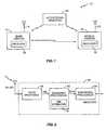
- FIG. 1illustrates an exemplary spread spectrum wireless communication network 10.
- the wireless communication network 10includes at least one base station 12, at least one mobile station 20, and possibly one or more interfering objects 18.
- the term "mobile station”may include a cellular radiotelephone with or without a multi-line display; a Personal Communications System (PCS) terminal that may combine a cellular radiotelephone with data processing, facsimile and data communications capabilities; a personal data assistant (PDA) that can include a radiotelephone, pager, Internet/intranet access, Web browser, organizer, calendar, and/or a global positioning system (GPS) receiver; and a conventional laptop and/or palmtop receiver or other appliance that includes a radiotelephone transceiver.
- Mobile stationsmay also be referred to as "pervasive computing" devices.
- Base station 12includes one or more antennas 14 for transmitting/receiving spread spectrum signals with one or more symbols to/from mobile station 20.
- the transmitted signalstypically include traffic and pilot signals.
- Objectssuch as interfering object 18, cause multiple "echoes" or delayed versions of the transmitted symbols to arrive at mobile station 20 at different times.
- Receiver 16processes the multiple symbol images at mobile station 20.
- mobile station 20may transmit symbols via one or more antennas 22 along multiple paths to base station 12, where receiver 16 processes the multiple received symbol images.
- FIG. 2illustrates an exemplary receiver 16 for base station 12 and/or mobile station 20.
- Receiver 16receives and processes the symbols of the received signals to generate received symbol estimates.
- An exemplary receiver 16includes a receiver front end 26, a baseband processor 30, and an additional processor 28.
- Receiver front end 26typically includes filters, mixers, and/or conversion circuits, such as analog-to-digital converters, to produce a series of digitized baseband signal samples r(t) corresponding to the received signal.
- Baseband processor 30demodulates the baseband signal r(t) to produce symbol estimates ⁇ (m) corresponding to the received signal.
- the symbol estimates ⁇ (m)are then processed further, as necessary, in additional processor 28.
- additional processor 28may include a turbo decoder (not shown) that determines information bit values based on the symbol estimates provided by the baseband processor 30. These information bit values may then be converted to speech, images, etc.
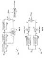
- baseband processor 30may include a signal-to-interference ratio (SIR) estimator 32 for estimating an SIR from the baseband signal r(t).
- SIR estimator 32athat includes despread unit 34, channel estimator 36, magnitude squared calculator 38, noise power estimator 40, divider 42, and accumulator 44.
- Despread unit 34despreads the received signal to generate a vector of despread symbols or values y .
- Each element of the vector of despread symbols ycorresponds to different timing offsets associated with different signal paths of the multi-path channel.
- channel estimator 36Based on each element of the vector of despread symbols y, channel estimator 36 generates a vector of channel estimates c .
- Magnitude squared calculator 38generates a vector of signal power estimates ⁇ based on each element of the vector of channel estimates c . Further, noise power estimator 40 generates a vector of noise power estimates N ⁇ based on the despread symbols y and the channel estimates c . Divider 42 divides each element in the vector of signal power estimates ⁇ by the corresponding element in the vector of noise power estimates N ⁇ to generate a vector of initial finger SIR estimates SIR init . The elements of the vector of initial finger SIR estimates SIR init are accumulated in accumulator 44 to produce a final SIR estimate SIR final corresponding to the baseband signal r(t). While the SIR estimator 32a of Figure 3 generates an SIR final appropriate for real-time operations, it does not account for the bias caused by the noisy channel estimates used to generate the SIR final .
- One way to reduce the bias associated with the SIR estimateis to reduce the noise present in the channel estimates c used to generate the SIR estimate. At low Doppler spreads, this may be accomplished by smoothing the channel estimates c over time. However, time sensitive network operations that rely on accurate SIR estimates often cannot wait the amount of time required to smooth the channel estimates c . As such, this method is not useful for time sensitive operations.
- SIR estimator 32Another way to reduce bias is to generate an initial SIR estimate and to remove bias from the initial SIR estimate.
- Figure 4illustrates this SIR estimator 32a.
- SIR estimator 32aincludes a signal power estimator 46, a signal combiner 48, a noise power estimator 50, a noise combiner 52, and a divider 54.
- Signal power estimator 46 and noise power estimator 50generate a signal power estimate ⁇ and noise power estimate N ⁇ , respectively, directly from the baseband signal r(t).
- the SIR estimator 32a of Figure 4removes signal bias by subtracting an estimate of the signal bias from the signal power estimate ⁇ in signal combiner 48 to generate a modified signal power estimate ⁇ '.
- noise combiner 52subtracts an estimate of the noise bias from the noise power estimate N ⁇ to generate a modified noise power estimate N ⁇ '.
- Divider 54divides the modified signal power estimate ⁇ ' by the modified noise power estimate N ⁇ ' to generate the final SIR estimate (SIR final ) corresponding to the baseband signal r(t). While this embodiment accounts for the bias, this embodiment is also prone to errors caused by overestimating the signal or noise bias terms, which may result in a negative SIR final .
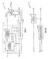
- FIG. 5illustrates a block diagram of an exemplary SIR estimator 32b according to the present invention.
- SIR estimator 32bprovides a final SIR estimate (SIR final ) that accounts for bias without introducing the subtraction errors caused by past SIR estimation approaches.
- SIR estimator 32bcomprises a despread unit 34, a channel estimator 36, a noise statistics estimator 56, and an SIR processor 100.
- Despread unit 34despreads the baseband signal r(t) to generate a vector of despread symbols y .
- each element of the vector of despread symbolscorresponds to different timing offsets associated with different signal paths of the multi-path channel.
- channel estimator 36Based on the despread symbols, channel estimator 36 generates a vector of channel estimates c according to any means known in the art.
- the despread values yare also provided to the noise statistics estimator 56.
- Noise statistics estimator 56estimates the noise statistics between the despread symbols y from different path delays.
- the noise statisticsmay be any statistics that represent the noise elements of the despread symbols y , such as 2 nd order statistics or correlations between the noise on the despread symbols. Because those skilled in the art will appreciate that “covariance” is a special case of “cross-correlation” with zero mean, the terms “correlation” and “covariance,” as used herein, should be understood as interchangeable unless the context of a particular passage makes an explicit distinction between the two terms.
- a noise statistics matrix, referred to herein as noise correlation matrix R Nmay be obtained, for example, by setting R N equal to M .
- noise correlation matrix R Nmay be obtained by smoothing past M values, using an exponential filter, and then setting R N equal to the smoothed M . It will be appreciated that because M and R N are Hermitian symmetric, only the upper or lower triangles of these matrices have to be computed, which greatly simplifies the calculation complexity.
- noise correlation matrix R Nmay be calculated according to any means known in the art. Exemplary methods are described in U.S. Patent Application Serial No. 10/811699 entitled “Impairment Correlation Estimation in a Spread Spectrum System” and filed 29 March 2004, and U.S. Patent Application Serial No. 10/800167 entitled “Method and Apparatus for Parameter Estimation in a Generalized RAKE Receiver” and filed 12 March 2004.
- SIR processor 100derives SIR final from the channel estimates c and the noise correlation matrix R N as described further below. It will be appreciated that due to the time sensitive nature of SIR estimation for some network operations, channel estimates c refer to values that may be formed using short-term data for the purposes of SIR estimation. Therefore, the SIR estimation channel estimates c may differ from the channel estimates calculated for a demodulator, where time delays are not as critical. As a result, a demodulator (not shown) in baseband processor 30 may use a different channel estimator that generates different channel estimates based on, for example, long-term data. While the present invention describes an SIR processor 100 that uses different channel estimates than those used in the demodulator, it will be appreciated by those skilled in the art that the SIR processor 100 and the demodulator could share channel estimates provided by a single channel estimator to simplify the receiver architecture.
- FIG. 6illustrates an exemplary embodiment of an SIR processor 100 according to the present invention.
- the SIR processor 100 of Figure 6assumes that the noise on the despread symbols y is correlated, which may occur due to dispersive channel interference and/or filters in the receiver front-end 26.
- SIR processor 100comprises an initial SIR calculator 102, an average SIR calculator 104, and a bias remover 106.
- Initial SIR calculator 102includes a weight calculator 108, a signal power estimator 110, a noise power estimator 116, and a divider 120 for deriving an initial SIR estimate (SIR init ) based on channel estimates c and noise correlation matrix R N .
- the SIR estimation weighting factors wmay differ from the weighting factors calculated for a demodulator, where time delays are not as critical.
- the SIR processor 100 of the present inventionincludes a weight calculator 108 that may derive weighting factors w different from those used by the demodulator.
- the SIR estimator 32b and the demodulatorcould share weighting factors provided by a single weight calculator to simplify the receiver architecture.
- initial SIR calculator 102calculates the signal and noise power estimates used to compute SIR init . More particularly, signal power estimator 110 generates an estimate of the overall signal power ⁇ based on the channel estimates c and the weighting factors w according to any means known in the art.
- Figure 6Aillustrates an exemplary signal power estimator 110.
- Noise power estimator 116generates an overall noise power estimate N ⁇ based on the noise correlation matrix R N and the weighting factors w according to any means known in the art.
- Bias remover 106further refines SIR init by removing bias from SIR init using an average SIR estimate ( SIR ) generated by average SIR calculator 104.
- bias remover 106comprises a multiplier that multiplies the initial SIR estimate SIR init by a scaling factor f derived from the average SIR estimate SIR . By multiplying SIR init by an average SIR based scaling factor f , bias remover 106 removes bias from the initial SIR estimate SIR init to generate the final SIR estimate SIR final .
- Figure 6Cillustrates an exemplary average SIR calculator 104 for the SIR processor 100 of Figure 6 .
- Average SIR calculator 104includes a signal statistics estimator 122, a signal quadratic computer 124, a noise quadratic computer 126, and a divider 128. While Figure 6C illustrates separate quadratic computers 124, 126 for calculating the average signal and noise powers, respectively, those skilled in the art will appreciate that these quadratic computers 124, 126 may be combined into a single quadratic computer that calculates both of the average signal and noise powers.
- Signal statistics estimator 122calculates a signal correlation matrix Q based on the channel estimates c and the noise correlation matrix R N .
- An exemplary signal statistics estimator 122is shown in Figure 6D .
- Signal statistics estimator 122comprises an outer product calculator 132, a smoothing filter 134, a multiplier 136, and a combiner 138.
- Smoothing filter 134smoothes the outer product of the channel estimates c, provided by outer product calculator 132, over time to generate a channel estimate correlation matrix P shown in Equation 8:
- PE cc H , where E ⁇ denotes the expected value. It will be appreciated that because P is Hermitian symmetric, only the upper or the lower triangles of the channel estimate correlation matrix have to be computed, which can greatly simplify the calculation complexity of the present invention.
- channel estimate correlation matrix Prepresents a biased estimate of the signal correlation matrix Q . Therefore, to remove the bias, signal statistics estimator 122 subtracts a scaled version of the noise correlation matrix, provided by multiplier 136, in combiner 138 to generate the signal correlation matrix Q , as shown in Equation 9:
- Kmay also include relative power or energy levels between pilot and traffic data. When K is large, or when there is interest in simplifying operations, Q may be set equal to P .
- Divider 128generates the average SIR ( SIR ) by dividing the average signal power S by the average noise power N .
- FIG. 6Eillustrates an exemplary bias remover 106 for the SIR processor 100 of Figure 6 .
- Bias remover 106includes a converter 130 and a multiplier 131.
- Multiplier 131removes bias from the initial SIR estimate SIR init and generates the final SIR estimate SIR final by scaling the initial SIR estimate SIR init using the scaling factor f provided by converter 130.
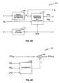
- the SIR processor 100 of Figure 7comprises an initial SIR calculator 150, a bias remover 154, and an average SIR calculator 156.
- SIR initc H ⁇ R N - 1 ⁇ c .
- Gauss-Seidelmay be used to obtain R N -1 c first.
- bias remover 154uses an average SIR estimate SIR provided by average SIR calculator 156 to remove bias from SIR init .
- Figure 7Aillustrates an exemplary average SIR calculator 156 for the SIR processor 100 shown in Figure 7 .
- Average SIR calculator 156comprises a signal statistics estimator 158, which generates a signal correlation matrix Q as described above.
- the Trace of a matrixmay be computed in any of a number of ways.
- Equation 15may be solved using the Gauss-Seidel or Gauss-Jordan iterative approach, for example.
- Equation 15Another way to solve Equation 15, and therefore to approximate the Trace of the product of R N -1 and Q , is to assume that the noise correlation matrix R N and the signal correlation matrix Q are diagonal. This may be established by ignoring the off-diagonal elements of R N and Q and/or setting the off-diagonal elements to zero.
- the average SIR estimate SIRmay be approximated as the sum of the delay path SIR values, where the delay path SIR values are obtained by dividing the diagonal elements of Q (delay path signal powers) by the diagonal elements of R N (delay path noise powers), as shown in Equation 16:
- Equation 13may be approximated as the sum of the delay path SIR values, where each finger has its own average signal and noise power.
- bias remover 154removes bias from the initial SIR estimate SIR init using the average SIR estimate SIR .
- bias remover 154comprises a multiplier that multiplies SIR init by a scaling factor f derived from SIR .
- Figure 8illustrates still another exemplary embodiment of an SIR processor 100.
- This embodimentuses an approximate form of joint scaling, which is an extension of G-RAKE used to account for noisy channel estimates when forming combining weights.
- the SIR processor 100 of Figure 8also includes an initial SIR calculator 170, an average SIR calculator 180, and a bias remover 190.
- initial SIR calculator 170refines the channel estimates c before calculating SIR init .
- initial SIR calculator 170comprises a channel estimation processor 174 and an inverse quadratic computer 172.
- Channel estimation processor 174shown in Figure 8A , includes a channel estimation matrix calculator 176 and a matrix multiplier 178.
- MMSEMinimum Mean Square Error
- Channel estimation processor 174refines the original channel estimates c by applying the channel estimation matrix A to the channel estimates c in matrix multiplier 178 to generate the modified channel estimates c ⁇ .
- the embodiment of Figure 8is similar to the embodiment of Figure 7 . The primary difference is the modification of the channel estimates c by channel estimation matrix A that produces the modified channel estimates c ⁇ .
- channel estimation matrix Aalso modifies the average SIR estimate SIR .
- Figure 8Billustrates an exemplary average SIR calculator 180 for the SIR processor 100 of Figure 8 .
- average SIR calculator 180 of Figure 8Bcomprises a signal statistics estimator 182.
- average SIR calculator 180includes a matrix squared calculator 184 and a modified average SIR processor 186 that replaces the average SIR processor 160 of Figure 7A .
- modified average SIR processor 186computes two average SIR estimates, SIR 1 and SIR 2 .
- FIG 8Cillustrates an exemplary bias remover 190 for the SIR processor 100 of Figure 8 that removes bias from SIR init using SIR 1 and SIR 2 .
- Bias remover 190includes a converter 188 and a multiplier 189.
- a H Amay be approximated as the identity matrix, and SIR 1 and SIR 2 may be computed according to the methods described above with reference to Figure 7 .
- multiplier 189removes bias from the SIR init to generate the final SIR estimate SIR final by scaling the initial SIR estimate SIR init using the scaling factor f provided by converter 188.
- FIG. 9shows an exemplary method for implementing the present invention.
- the SIR processor 100calculates an initial SIR estimate SIR init based on the received signal (Block 200). Further, SIR processor 100 generates an average SIR estimate SIR based on the received signal (Block 210). Using the average SIR estimate SIR , SIR processor 100 removes bias from the initial SIR estimate SIR init to generate the final SIR estimate SIR final (Block 220).
- SIR processor 100 of the present inventionis shown having various separate components, those skilled in the art will appreciate that two or more of these components may be combined into the same functional circuit. Further, those skilled in the art will appreciate that one or more of these circuits may be embodied in hardware and/or software (including firmware, software, micro-code, etc.), including an application specific integrated circuit (ASIC), field programmable gate array (FPGA), etc. Software or code to implement the present invention may be stored in any known computer readable medium.
- ASICapplication specific integrated circuit
- FPGAfield programmable gate array
- a scaling factor fmay be derived from the average SIR estimate SIR , that in turn is derived from the baseband signal r(t).
- the SIR processor 100 of the present inventionremoves bias present in SIR init using the average SIR estimate SIR .
- SIRmay be approximated by smoothing past final SIR values.
- a target SIR used in a power control loop, a nominal SIR, or a worst case SIRmay be defined as the SIR and used to calculate the scaling factor f .
- the resulting final SIR estimate SIR finalmay be used in real-time operations, such as power control, rate adaptation, etc.
- the present inventionmay avoid the problem of a negative final SIR estimate SIR final by multiplying the initial SIR estimate SIR init by a scaling factor f to remove bias.
- the multiplicative approach of the present inventionas compared to the conventional subtractive approach, may improve the accuracy of a final SIR estimate by 20% for a standard RAKE receiver. The accuracy improvements are even greater (40% - 70%) in receivers that use a grid approach to finger placement, as described in U.S. Patent Application Serial No.
- final SIR estimatemay also be used to determine a long term SIR.
- final SIR estimates computed over one or more framesmay be averaged to generate a long-term SIR estimate.
- This long-term SIR estimatemay be provided to a base station or other network entity as a long-term quality measure.
- SIR processor 100may use the long-term SIR estimate as the average SIR estimate used to calculate the scaling factor f .
- these despread symbolsmay be based on pilot symbols, data symbols, and/or a pilot channel that is treated as a continuous series of pilot symbols.
- the number of symbols and/or the type of symbolsmay be selectively changed based on the current channel conditions. For example, a Doppler spread estimator may be used to determine how quickly a channel is changing. If the channel is changing rapidly, only the symbols from a single time slot, for example, may be used. If the channel is changing slowly, then symbols from multiple past slots may be used. For the slowly changing channels, channel estimator 36 and/or noise statistics estimator 56 may exponentially weight the contributions from older slots and/or compensate each slot for changes in the transmit power due to power control.
- the present inventionis not so limiting and may be applied to networks with multiple transmit and/or receive antennas.
- fingers of the spread spectrum receiverare assigned to certain paths from certain antennas. Therefore, vector quantities, such as the despread symbols, channel estimates, etc., may still be collected into vectors.
- the elements in the vectorshave both a path and an antenna index. For example, when there are two receive antennas, where each antenna receives signals from two different paths, the vector quantities are of length four and the matrices are of size 4x4.
- SIR processor 100may separately generate an initial SIR estimate for each transmitted signal and then sum the individual initial SIR estimates to obtain an overall initial SIR estimate SIR init .
- bias removalmay occur either before or after the summation.
- present inventionmay be used with transmit diversity systems.
Landscapes
- Engineering & Computer Science (AREA)
- Computer Networks & Wireless Communication (AREA)
- Signal Processing (AREA)
- Quality & Reliability (AREA)
- Physics & Mathematics (AREA)
- Electromagnetism (AREA)
- Mobile Radio Communication Systems (AREA)
- Monitoring And Testing Of Transmission In General (AREA)
- Circuits Of Receivers In General (AREA)
- Input Circuits Of Receivers And Coupling Of Receivers And Audio Equipment (AREA)
- Noise Elimination (AREA)
Abstract
Description
- The present invention relates generally to signal processing in a wireless network and more particularly to estimating a signal-to-interference ratio (SIR) in a wireless receiver.
- Receivers in wireless networks typically calculate performance parameters to evaluate the receiver and/or to assess certain network level parameters, such as transmit power, data rate, etc. One performance parameter of particular interest to wireless receivers in a spread spectrum network is the signal-to-interference ratio (SIR) associated with the received signals. Conventional receivers typically calculate the SIR associated with the received signals and use the calculated SIR to adapt the network level parameters to current channel conditions. For example, the calculated SIR may be used to control mobile station transmit power, data transmission rate, mobile station scheduling, etc.
- The accuracy of network adaptation to current channel conditions depends on the accuracy of the SIR estimates as well as the amount of time expended to generate the SIR estimates. Currently, there are many ways to estimate the SIR in a spread spectrum network. For example, the receiver may use a combination of chip samples and despread symbols to estimate the SIR. While this approach may provide accurate SIR estimates in a timely manner, this approach requires a complex receiver architecture with access to both chip samples and despread values.
- Another receiver may use symbol estimates provided by a RAKE receiver output to estimate the SIR. However, because current RAKE output symbols correspond to symbols received well in the past, the resulting SIR does not correspond to current receiver performance and channel conditions. Therefore, while this approach requires a significantly less complex receiver architecture, the resulting SIR estimates are insufficient for real-time operations, such as power control, rate adaptation, etc.
- Still other receivers may use despread symbols (pilot or data) to generate a finger SIR for each finger of a RAKE receiver. Summing the finger SIRs provides an SIR estimate that may be used for real-time operations. However, because the despread symbols typically contain a considerable amount of noise, the resulting SIR estimate is often biased. Conventional networks may remove this bias by subtracting an estimate of the bias from the current SIR estimate. However, the bias estimation process can overestimate the bias. As a result, using subtraction to remove the bias can result in negative, and therefore inaccurate, SIR estimates.
EP-A-1239615 describes a method and apparatus that removes bias from a SIR estimate by computing a corrected SIR using mean values of the signal and noise powers and correction coefficients.- The present invention describes a method and apparatus that removes bias from an initial estimate of signal-to-interference ratio (SIR). In an exemplary embodiment, an SIR processor in an SIR estimator of a wireless receiver comprises an initial SIR calculator, an average SIR calculator, and a bias remover. The initial SIR calculator calculates the initial SIR based on the signal received by the wireless receiver, while the average SIR calculator generates an average SIR. Using the average SIR, the bias remover removes the bias from the initial SIR.
- In an exemplary embodiment, the SIR estimator derives despread values from the baseband signal r(t). The SIR estimator uses the despread values to generate channel estimates and noise statistics, which are in turn used by the SIR processor to calculate the initial and average SIR estimates.
- Further, according to an exemplary embodiment of the present invention, the bias remover generates a scaling factor based on the average SIR and an offset parameter, where the offset parameter is derived from a count of the despread values processed by the wireless receiver. In this embodiment, the bias remover comprises a converter that generates the scaling factor and a multiplier that multiplies the initial SIR by the scaling factor to remove the bias from the initial SIR.
Figure 1 illustrates an exemplary wireless network.Figure 2 illustrates an exemplary wireless receiver in the wireless network ofFigure 1 .Figure 3 illustrates a block diagram of an SIR estimator.Figure 4 illustrates a block diagram of another SIR estimator.Figure 5 illustrates a block diagram of an exemplary SIR estimator according to the present invention.Figure 6 illustrates a block diagram of an exemplary SIR processor for the SIR estimator ofFigure 5 .Figures 6A and 6B illustrate block diagrams of exemplary signal and noise power estimators, respectively, for the SIR processor ofFigure 6 .Figure 6C illustrates a block diagram of an exemplary average SIR calculator for the SIR processor ofFigure 6 .Figure 6D illustrates a block diagram of an exemplary signal statistics estimator for the average SIR calculator ofFigure 6C .Figure 6E illustrates a block diagram of an exemplary bias remover for the SIR processor ofFigure 6 .Figure 7 illustrates a block diagram of another exemplary SIR processor for the SIR estimator ofFigure 5 .Figure 7A illustrates a block diagram of an exemplary average SIR calculator for the SIR processor ofFigure 7 .Figure 8 illustrates a block diagram of another exemplary SIR processor for the SIR estimator ofFigure 5 .Figure 8A illustrates a block diagram of an exemplary channel estimation processor for the SIR processor ofFigure 8 .Figure 8B illustrates a block diagram of an exemplary average SIR calculator for the SIR processor ofFigure 8 .Figure 8C illustrates a block diagram of an exemplary bias remover for the SIR processor ofFigure 8 .Figure 9 illustrates an exemplary flow chart for the method of the present invention.Figure 1 illustrates an exemplary spread spectrumwireless communication network 10. Thewireless communication network 10 includes at least onebase station 12, at least onemobile station 20, and possibly one or moreinterfering objects 18. As used herein, the term "mobile station" may include a cellular radiotelephone with or without a multi-line display; a Personal Communications System (PCS) terminal that may combine a cellular radiotelephone with data processing, facsimile and data communications capabilities; a personal data assistant (PDA) that can include a radiotelephone, pager, Internet/intranet access, Web browser, organizer, calendar, and/or a global positioning system (GPS) receiver; and a conventional laptop and/or palmtop receiver or other appliance that includes a radiotelephone transceiver. Mobile stations may also be referred to as "pervasive computing" devices.Base station 12 includes one ormore antennas 14 for transmitting/receiving spread spectrum signals with one or more symbols to/frommobile station 20. The transmitted signals typically include traffic and pilot signals. Objects, such as interferingobject 18, cause multiple "echoes" or delayed versions of the transmitted symbols to arrive atmobile station 20 at different times. Receiver 16 processes the multiple symbol images atmobile station 20. Similarly,mobile station 20 may transmit symbols via one ormore antennas 22 along multiple paths tobase station 12, wherereceiver 16 processes the multiple received symbol images.Figure 2 illustrates anexemplary receiver 16 forbase station 12 and/ormobile station 20.Receiver 16 receives and processes the symbols of the received signals to generate received symbol estimates. Anexemplary receiver 16 includes areceiver front end 26, abaseband processor 30, and anadditional processor 28.Receiver front end 26 typically includes filters, mixers, and/or conversion circuits, such as analog-to-digital converters, to produce a series of digitized baseband signal samples r(t) corresponding to the received signal.Baseband processor 30 demodulates the baseband signal r(t) to produce symbol estimates ŝ(m) corresponding to the received signal. The symbol estimates ŝ(m) are then processed further, as necessary, inadditional processor 28. For example,additional processor 28 may include a turbo decoder (not shown) that determines information bit values based on the symbol estimates provided by thebaseband processor 30. These information bit values may then be converted to speech, images, etc.- As shown in
Figure 2 ,baseband processor 30 may include a signal-to-interference ratio (SIR)estimator 32 for estimating an SIR from the baseband signal r(t).Figure 3 illustrates anSIR estimator 32a that includesdespread unit 34,channel estimator 36, magnitude squaredcalculator 38,noise power estimator 40,divider 42, andaccumulator 44.Despread unit 34 despreads the received signal to generate a vector of despread symbols or valuesy. Each element of the vector of despread symbolsy corresponds to different timing offsets associated with different signal paths of the multi-path channel. Based on each element of the vector of despread symbols y,channel estimator 36 generates a vector of channel estimatesc. Magnitude squaredcalculator 38 generates a vector of signal power estimatesŜ based on each element of the vector of channel estimatesc. Further,noise power estimator 40 generates a vector of noise power estimatesN̂ based on the despread symbolsy and the channel estimatesc.Divider 42 divides each element in the vector of signal power estimatesŜ by the corresponding element in the vector of noise power estimatesN̂ to generate a vector of initial finger SIR estimatesSIRinit. The elements of the vector of initial finger SIR estimatesSIRinit are accumulated inaccumulator 44 to produce a final SIR estimate SIRfinal corresponding to the baseband signal r(t). While theSIR estimator 32a ofFigure 3 generates an SIR final appropriate for real-time operations, it does not account for the bias caused by the noisy channel estimates used to generate the SIRfinal. - One way to reduce the bias associated with the SIR estimate is to reduce the noise present in the channel estimates c used to generate the SIR estimate. At low Doppler spreads, this may be accomplished by smoothing the channel estimates c over time. However, time sensitive network operations that rely on accurate SIR estimates often cannot wait the amount of time required to smooth the channel estimatesc. As such, this method is not useful for time sensitive operations.
- Another way to reduce bias is to generate an initial SIR estimate and to remove bias from the initial SIR estimate.
WO 01/65717 SIR estimator 32 that may be used to remove bias from an initial SIR estimate.Figure 4 illustrates thisSIR estimator 32a. In this embodiment,SIR estimator 32a includes asignal power estimator 46, asignal combiner 48, anoise power estimator 50, anoise combiner 52, and adivider 54.Signal power estimator 46 andnoise power estimator 50 generate a signal power estimate Ŝ and noise power estimate N̂, respectively, directly from the baseband signal r(t). However, unlike theSIR estimator 32a ofFigure 3 , theSIR estimator 32a ofFigure 4 removes signal bias by subtracting an estimate of the signal bias from the signal power estimate Ŝ insignal combiner 48 to generate a modified signal power estimate Ŝ'. Similarly,noise combiner 52 subtracts an estimate of the noise bias from the noise power estimate N̂ to generate a modified noise power estimate N̂'.Divider 54 divides the modified signal power estimate Ŝ' by the modified noise power estimate N̂' to generate the final SIR estimate (SIRfinal) corresponding to the baseband signal r(t). While this embodiment accounts for the bias, this embodiment is also prone to errors caused by overestimating the signal or noise bias terms, which may result in a negative SIRfinal. Figure 5 illustrates a block diagram of anexemplary SIR estimator 32b according to the present invention.SIR estimator 32b provides a final SIR estimate (SIRfinal) that accounts for bias without introducing the subtraction errors caused by past SIR estimation approaches.SIR estimator 32b comprises adespread unit 34, achannel estimator 36, anoise statistics estimator 56, and anSIR processor 100.Despread unit 34 despreads the baseband signal r(t) to generate a vector of despread symbolsy. As understood by those skilled in the art, each element of the vector of despread symbols corresponds to different timing offsets associated with different signal paths of the multi-path channel. Based on the despread symbols,channel estimator 36 generates a vector of channel estimatesc according to any means known in the art. For example, channel estimate vectorc may be derived according to:
where K represents the number of pilot symbols processed by thereceiver 16, b(i) represents a known pilot symbol for theith symbol period, b* (i) represents the complex conjugate of b(i), and y(i) represents the vector of despread symbols or values from different path delays for theith symbol period.- The despread valuesy, along with the channel estimatesc, are also provided to the
noise statistics estimator 56.Noise statistics estimator 56 estimates the noise statistics between the despread symbolsy from different path delays. The noise statistics may be any statistics that represent the noise elements of the despread symbolsy, such as 2nd order statistics or correlations between the noise on the despread symbols. Because those skilled in the art will appreciate that "covariance" is a special case of "cross-correlation" with zero mean, the terms "correlation" and "covariance," as used herein, should be understood as interchangeable unless the context of a particular passage makes an explicit distinction between the two terms. - In an exemplary embodiment,
noise statistics estimator 56 estimates the correlation matrixM between the impairment on the despread symbolsy according to either of Equations 2A or 2B:

where superscript "H" denotes the conjugate transpose. A noise statistics matrix, referred to herein as noise correlation matrixRN, may be obtained, for example, by settingRN equal toM. Alternatively, noise correlation matrixRN may be obtained by smoothing pastM values, using an exponential filter, and then settingRN equal to the smoothedM. It will be appreciated that becauseM andRN are Hermitian symmetric, only the upper or lower triangles of these matrices have to be computed, which greatly simplifies the calculation complexity. - Those skilled in the art will appreciate that the present invention is not limited to the above described noise statistics calculation methods. Indeed, noise correlation matrixRN may be calculated according to any means known in the art. Exemplary methods are described in
U.S. Patent Application Serial No. 10/811699 entitled "Impairment Correlation Estimation in a Spread Spectrum System" and filed 29 March 2004, andU.S. Patent Application Serial No. 10/800167 entitled "Method and Apparatus for Parameter Estimation in a Generalized RAKE Receiver" and filed 12 March 2004. SIR processor 100 derives SIRfinal from the channel estimates c and the noise correlation matrixRN as described further below. It will be appreciated that due to the time sensitive nature of SIR estimation for some network operations, channel estimates c refer to values that may be formed using short-term data for the purposes of SIR estimation. Therefore, the SIR estimation channel estimates c may differ from the channel estimates calculated for a demodulator, where time delays are not as critical. As a result, a demodulator (not shown) inbaseband processor 30 may use a different channel estimator that generates different channel estimates based on, for example, long-term data. While the present invention describes anSIR processor 100 that uses different channel estimates than those used in the demodulator, it will be appreciated by those skilled in the art that theSIR processor 100 and the demodulator could share channel estimates provided by a single channel estimator to simplify the receiver architecture.Figure 6 illustrates an exemplary embodiment of anSIR processor 100 according to the present invention. TheSIR processor 100 ofFigure 6 assumes that the noise on the despread symbols y is correlated, which may occur due to dispersive channel interference and/or filters in the receiver front-end 26.SIR processor 100 comprises aninitial SIR calculator 102, anaverage SIR calculator 104, and abias remover 106.Initial SIR calculator 102 includes aweight calculator 108, asignal power estimator 110, anoise power estimator 116, and adivider 120 for deriving an initial SIR estimate (SIRinit) based on channel estimatesc and noise correlation matrixRN.- To that end,
weight calculator 108 calculates a vector of weighting factorsw based on the channel estimatesc according to any known means. For example, whenreceiver 16 includes a traditional RAKE receiver, weighting factorsw may be approximated according to Equation 3:
receiver 16 includes a generalized RAKE (G-RAKE) receiver,weight calculator 108 may use both the channel estimates c and the noise correlation matrixRN to calculate the weighting factors w according to:
U.S. Patent Application Serial No. 10/672127 
whereF depends on channel and noise statistics. In any event, it will be appreciated that, as with the channel estimates, weighting factorsw refer to values that may be formed using short-term data for the purposes of SIR estimation. Therefore, the SIR estimation weighting factorsw may differ from the weighting factors calculated for a demodulator, where time delays are not as critical. As a result, theSIR processor 100 of the present invention includes aweight calculator 108 that may derive weighting factorsw different from those used by the demodulator. However, it will be appreciated by those skilled in the art that theSIR estimator 32b and the demodulator could share weighting factors provided by a single weight calculator to simplify the receiver architecture. - Based on the calculated weighting factorsw,
initial SIR calculator 102 calculates the signal and noise power estimates used to compute SIRinit. More particularly, signalpower estimator 110 generates an estimate of the overall signal power Ŝ based on the channel estimatesc and the weighting factorsw according to any means known in the art.Figure 6A illustrates an exemplarysignal power estimator 110.Signal power estimator 110 includes aninner product calculator 112 and a magnitude squaredcalculator 114. Magnitude squaredcalculator 114 squares the magnitude of the inner product of the channel estimatesc and the weighting factorsw provided byinner product calculator 112 to generate the signal power estimate Ŝ, as shown in Equation 6:
Noise power estimator 116 generates an overall noise power estimate N̂ based on the noise correlation matrixRN and the weighting factorsw according to any means known in the art. An exemplarynoise power estimator 116 comprising aquadratic computer 118, as illustrated inFigure 6B , may derive the noise power estimate N̂ from the noise correlation matrixRN and the weighting factorsw according to Equation 7:
Divider 120 divides the signal power estimate Ŝ by the noise power estimate N̂ to generate the initial SIR estimate SIRinit.Bias remover 106 further refines SIRinit by removing bias from SIRinit using an average SIR estimate (SIR ) generated byaverage SIR calculator 104. In a preferred embodiment,bias remover 106 comprises a multiplier that multiplies the initial SIR estimate SIRinit by a scaling factorf derived from the average SIR estimateSIR . By multiplying SIRinit by an average SIR based scaling factorf, biasremover 106 removes bias from the initial SIR estimate SIRinit to generate the final SIR estimate SIRfinal.Figure 6C illustrates an exemplaryaverage SIR calculator 104 for theSIR processor 100 ofFigure 6 .Average SIR calculator 104 includes asignal statistics estimator 122, a signalquadratic computer 124, a noisequadratic computer 126, and adivider 128. WhileFigure 6C illustrates separatequadratic computers quadratic computers Signal statistics estimator 122 calculates a signal correlation matrixQ based on the channel estimates c and the noise correlation matrixRN. An exemplarysignal statistics estimator 122 is shown inFigure 6D .Signal statistics estimator 122 comprises anouter product calculator 132, a smoothingfilter 134, amultiplier 136, and acombiner 138.Smoothing filter 134 smoothes the outer product of the channel estimates c, provided byouter product calculator 132, over time to generate a channel estimate correlation matrixP shown in Equation 8:
where E{} denotes the expected value. It will be appreciated that becauseP is Hermitian symmetric, only the upper or the lower triangles of the channel estimate correlation matrix have to be computed, which can greatly simplify the calculation complexity of the present invention.- Because the channel estimates c include noise due to estimation error, channel estimate correlation matrixP represents a biased estimate of the signal correlation matrixQ. Therefore, to remove the bias,
signal statistics estimator 122 subtracts a scaled version of the noise correlation matrix, provided bymultiplier 136, incombiner 138 to generate the signal correlation matrixQ, as shown in Equation 9:
where β depends on the number (K) of despread symbols used to estimate the vector of channel estimatesc. K may also include relative power or energy levels between pilot and traffic data. When K is large, or when there is interest in simplifying operations,Q may be set equal toP. Signal statistics estimator 122 provides signal correlation matrixQ to signalquadratic computer 124, which calculates an average signal powerS according to Equation 10:
quadratic computer 126 uses noise correlation matrixRN to calculate an average noise powerN according to Equation 11:
Divider 128 generates the average SIR (SIR ) by dividing the average signal powerS by the average noise powerN .Figure 6E illustrates anexemplary bias remover 106 for theSIR processor 100 ofFigure 6 .Bias remover 106 includes aconverter 130 and amultiplier 131.Converter 130 derives a scaling factorf from the average SIR estimateSIR provided by the output ofaverage SIR calculator 104 according to:
where α represents an offset parameter derived from the number (K) of despread symbols used to generate the channel estimatesc. K may also include relative power or energy levels between pilot and traffic data. In a preferred embodiment, the offset parameter α may be calculated according to α = 1/K. Multiplier 131 removes bias from the initial SIR estimate SIRinit and generates the final SIR estimate SIRfinal by scaling the initial SIR estimate SIRinit using the scaling factorf provided byconverter 130.- Turning now to
Figure 7 , another embodiment of anexemplary SIR processor 100 will be described. Like theSIR processor 100 ofFigure 6 , theSIR processor 100 ofFigure 7 comprises aninitial SIR calculator 150, abias remover 154, and anaverage SIR calculator 156. For this embodiment, it is assumed that a G-RAKE receiver is used, where the weighting factors are calculated according to Equation 4. Therefore theinitial SIR calculator 150 can use an inversequadratic computer 152 to calculate the initial SIR estimate SIRinit according to:
- As with the first embodiment,
bias remover 154 uses an average SIR estimateSIR provided byaverage SIR calculator 156 to remove bias from SIRinit.Figure 7A illustrates an exemplaryaverage SIR calculator 156 for theSIR processor 100 shown inFigure 7 .Average SIR calculator 156 comprises asignal statistics estimator 158, which generates a signal correlation matrixQ as described above.Average SIR calculator 156 further comprises anaverage SIR processor 160 that uses the signal correlation matrixQ and the noise correlation matrixRN to calculate an average SIR estimateSIR according to:
where Tr{} denotes the Trace of the product ofRN-1 andQ. The Trace of a matrix may be computed in any of a number of ways. For example, one way to compute the Trace of the product ofRN-1 andQ is to solve for the columns of the product by solving:
whereq is a column ofQ. Equation 15 may be solved using the Gauss-Seidel or Gauss-Jordan iterative approach, for example. - Another way to solve Equation 15, and therefore to approximate the Trace of the product ofRN-1 andQ, is to assume that the noise correlation matrixRN and the signal correlation matrixQ are diagonal. This may be established by ignoring the off-diagonal elements ofRN andQ and/or setting the off-diagonal elements to zero. In either case, the average SIR estimate
SIR may be approximated as the sum of the delay path SIR values, where the delay path SIR values are obtained by dividing the diagonal elements ofQ (delay path signal powers) by the diagonal elements of RN (delay path noise powers), as shown in Equation 16:
wherein J represents the number of delay paths processed by the receiver. Because the off-diagonal elements are ignored (or set to zero), the off-diagonal elements ofQ do not need to be calculated, which saves processing time. This approach for estimatingSIR is particularly effective when the baseband processor includes a traditional RAKE receiver and the noise present in the different despread symbols is uncorrelated. It will be appreciated that the assumption that the noise correlation matrixRN is diagonal also simplifies the SIRinit calculation. As a result, Equation 13 may be approximated as the sum of the delay path SIR values, where each finger has its own average signal and noise power. - Still another way to approximate the Trace of the product ofRN-1 andQ is to assume that the noise correlation matrixRN is diagonal and that the noise associated with each delay path processed by the receiver is stationary noise, and therefore, has the same noise power N. As a result, the diagonal elements of the noise correlation matrixRN are equivalent. Therefore,
SIR may be computed according to:
where J represents the number of fingers or delay paths processed by the receiver. It will be appreciated that the assumption that the noise correlation matrixRN is diagonal also simplifies the SIRinit calculation. As a result, Equation 13 simplifies to the sum of the finger signal power values divided by the noise power N. - Once
SIR is calculated, biasremover 154 removes bias from the initial SIR estimate SIRinit using the average SIR estimateSIR . In an exemplary embodiment,bias remover 154 comprises a multiplier that multiplies SIRinit by a scaling factorf derived fromSIR . For this embodiment,bias remover 154 may compute theSIR based scaling factorf inconverter 130 ofFigure 6E according to:
where α is an offset parameter that may be calculated according to α = J/K , where J represents the number of delay paths processed by the receiver and K represents the number of symbols used to calculate the channel estimates c. Figure 8 illustrates still another exemplary embodiment of anSIR processor 100. This embodiment uses an approximate form of joint scaling, which is an extension of G-RAKE used to account for noisy channel estimates when forming combining weights. As with the previous embodiments, theSIR processor 100 ofFigure 8 also includes aninitial SIR calculator 170, anaverage SIR calculator 180, and abias remover 190. However, in this embodiment,initial SIR calculator 170 refines the channel estimates c before calculating SIRinit.- To that end,
initial SIR calculator 170 comprises achannel estimation processor 174 and an inversequadratic computer 172.Channel estimation processor 174, shown inFigure 8A , includes a channelestimation matrix calculator 176 and amatrix multiplier 178. Channelestimation matrix calculator 176 computes a channel estimation matrix A according to:
where K represents the number of despread symbols used to calculate the channel estimates c and may also include the effects of power level differences between pilot and traffic data. Because channel estimation matrixA depends on the signal statisticsQ and the noise statisticsRN, as shown in Equation 19, channel estimation matrixA provides a form of MMSE (Minimum Mean Square Error) channel estimation. Channel estimation processor 174 refines the original channel estimates c by applying the channel estimation matrix A to the channel estimatesc inmatrix multiplier 178 to generate the modified channel estimatesc̃.Initial SIR calculator 170 then calculates the initial SIR estimate SIRinit in inversequadratic computer 172 using the modified channel estimatesc̃, as shown in Equation 20:
Equation 20, the embodiment ofFigure 8 is similar to the embodiment ofFigure 7 . The primary difference is the modification of the channel estimatesc by channel estimation matrixA that produces the modified channel estimatesc̃.- Further, channel estimation matrixA also modifies the average SIR estimate
SIR .Figure 8B illustrates an exemplaryaverage SIR calculator 180 for theSIR processor 100 ofFigure 8 . As with theaverage SIR calculator 156 ofFigure 7A ,average SIR calculator 180 ofFigure 8B comprises asignal statistics estimator 182. In addition,average SIR calculator 180 includes a matrix squaredcalculator 184 and a modifiedaverage SIR processor 186 that replaces theaverage SIR processor 160 ofFigure 7A . In the embodiment ofFigure 8B , modifiedaverage SIR processor 186 computes two average SIR estimates,SIR 1 andSIR 2. The first average SIR estimateSIR 1 is calculated according toEquation 14, which is repeated here as Equation 21:
SIR 2 is derived from the square of the channel estimation matrix A provided by matrix squaredcalculator 184, as well as the signal correlation matrixQ and the noise correlation matrixRN, as shown by Equation 22:
Equation 22,SIR 2 essentially has a scaling down factor that depends on the channel estimation matrix A, which intuitively accounts for the noise in the channel estimates c. Figure 8C illustrates anexemplary bias remover 190 for theSIR processor 100 ofFigure 8 that removes bias from SIRinit usingSIR 1 andSIR 2.Bias remover 190 includes aconverter 188 and amultiplier 189. Using theSIR 1 andSIR 2 provided byaverage SIR calculator 180,converter 188 may compute a scaling factorf according to:
where α may be calculated as α = (1/K)Tr{AHA}. In some embodiments it may be desirable to simplify the computations associated withSIR 1 andSIR 2. To that end,AHA may be approximated as the identity matrix, andSIR 1 andSIR 2 may be computed according to the methods described above with reference toFigure 7 . In any event,multiplier 189 removes bias from the SIRinit to generate the final SIR estimate SIRfinal by scaling the initial SIR estimate SIRinit using the scaling factorf provided byconverter 188.- The above describes a method and an apparatus for removing bias from an initial SIR estimate SIRinit to calculate a final SIR estimate SIRfinal.
Figure 9 shows an exemplary method for implementing the present invention. According to the present invention, theSIR processor 100 calculates an initial SIR estimate SIRinit based on the received signal (Block 200). Further,SIR processor 100 generates an average SIR estimate SIR based on the received signal (Block 210). Using the average SIR estimateSIR ,SIR processor 100 removes bias from the initial SIR estimate SIRinit to generate the final SIR estimate SIRfinal (Block 220). - While the
SIR processor 100 of the present invention is shown having various separate components, those skilled in the art will appreciate that two or more of these components may be combined into the same functional circuit. Further, those skilled in the art will appreciate that one or more of these circuits may be embodied in hardware and/or software (including firmware, software, micro-code, etc.), including an application specific integrated circuit (ASIC), field programmable gate array (FPGA), etc. Software or code to implement the present invention may be stored in any known computer readable medium. - As shown in
Figures 6-8 and in the above description, a scaling factorf may be derived from the averageSIR estimateSIR , that in turn is derived from the baseband signal r(t). As a result, theSIR processor 100 of the present invention removes bias present in SIRinit using the average SIR estimateSIR . While the above describes several ways to calculateSIR , the present invention is not limited to these methods. For example,SIR may be approximated by smoothing past final SIR values. Further, it will be appreciated that a target SIR used in a power control loop, a nominal SIR, or a worst case SIR may be defined as theSIR and used to calculate the scaling factorf. - Because the above described method and apparatus may compute SIRfinal relatively instantaneously, the resulting final SIR estimate SIRfinal may be used in real-time operations, such as power control, rate adaptation, etc. Further, unlike past solutions, the present invention may avoid the problem of a negative final SIR estimate SIRfinal by multiplying the initial SIR estimate SIRinit by a scaling factorf to remove bias. Preliminary tests have shown that the multiplicative approach of the present invention, as compared to the conventional subtractive approach, may improve the accuracy of a final SIR estimate by 20% for a standard RAKE receiver. The accuracy improvements are even greater (40% - 70%) in receivers that use a grid approach to finger placement, as described in
U.S. Patent Application Serial No. 10/653679 - While the above describes calculating a final SIR estimate SIRfinal for real-time operations, it will be appreciated by those skilled in the art that the final SIR estimate may also be used to determine a long term SIR. For example, final SIR estimates computed over one or more frames may be averaged to generate a long-term SIR estimate. This long-term SIR estimate may be provided to a base station or other network entity as a long-term quality measure. Further, once this long-term SIR estimate is computed,
SIR processor 100 may use the long-term SIR estimate as the average SIR estimate used to calculate the scaling factorf. - The above also describes the invention in terms of despread symbols y derived from the baseband signal r(t). It will be appreciated by those skilled in the art that these despread symbols may be based on pilot symbols, data symbols, and/or a pilot channel that is treated as a continuous series of pilot symbols. Further still, the number of symbols and/or the type of symbols may be selectively changed based on the current channel conditions. For example, a Doppler spread estimator may be used to determine how quickly a channel is changing. If the channel is changing rapidly, only the symbols from a single time slot, for example, may be used. If the channel is changing slowly, then symbols from multiple past slots may be used. For the slowly changing channels,
channel estimator 36 and/ornoise statistics estimator 56 may exponentially weight the contributions from older slots and/or compensate each slot for changes in the transmit power due to power control. - While the above wireless network was described in terms of a single transmit and/or receive antenna, the present invention is not so limiting and may be applied to networks with multiple transmit and/or receive antennas. In this case, fingers of the spread spectrum receiver are assigned to certain paths from certain antennas. Therefore, vector quantities, such as the despread symbols, channel estimates, etc., may still be collected into vectors. However, for the multiple transmit/receive antenna system, the elements in the vectors have both a path and an antenna index. For example, when there are two receive antennas, where each antenna receives signals from two different paths, the vector quantities are of length four and the matrices are of size 4x4. Further, for the multiple transmit antenna system in which different scrambled spreading codes are used on the different transmit antennas, it is typically reasonable to assume that noise and fading terms are uncorrelated. As a result,
SIR processor 100 may separately generate an initial SIR estimate for each transmitted signal and then sum the individual initial SIR estimates to obtain an overall initial SIR estimate SIRinit. In this scenario, bias removal may occur either before or after the summation. It will also be appreciated that the present invention may be used with transmit diversity systems. - The present invention may, of course, be carried out in other ways than those specifically set forth herein without departing from essential characteristics of the invention. The present embodiments are to be considered in all respects as illustrative and not restrictive, and all changes coming within the meaning and equivalency range of the appended claims are intended to be embraced therein.


Claims (46)
- A method of removing bias from an initial signal-to-interference ratio generated by a wireless receiver comprising:calculating the initial signal-to-interference ratio based on a signal received by the wireless receiver;generating an average signal-to-interference ratio; andusing the average signal-to-interference ratio to remove the bias from the initial signal-to-interference ratio.
- The method of claim 1 wherein generating the average signal-to-interference ratio comprises calculating the average signal-to-interference ratio based on channel estimates and noise statistics derived from the received signal.
- The method of claim 2 wherein calculating the average signal-to-interference ratio based on channel estimates and noise statistics derived from the received signal comprises calculating the average signal-to-interference ratio based on channel estimates and noise statistics derived from despread values of the received signal.
- The method of claim 2 wherein using the average signal-to-interference ratio to remove the bias from the initial signal-to-interference ratio comprises:generating a scaling factor based on the average signal-to-interference ratio; andmultiplying the initial signal-to-interference ratio by the scaling factor to remove the bias.
- The method of claim 4 wherein generating the scaling factor based on the average signal-to-interference ratio includes modifying the average signal-to-interference ratio by an offset parameter.
- The method of claim 5 wherein generating the average signal-to-interference ratio comprises:calculating a signal correlation matrix based on the channel estimates; andcalculating the average signal-to-interference ratio based on the signal correlation matrix and the noise statistics.
- The method of claim 6 wherein generating the scaling factor based on the average signal-to-interference ratio comprises generating the scaling factor according to:

whereSIR represents the average signal-to-interference ratio and α represents the offset parameter. - The method of claim 7 wherein the offset parameter is derived from at least one of a count of despread values processed by the wireless receiver to generate the channel estimates and a count of the paths of a multi-path channel processed by the wireless receiver.
- The method of claim 6 wherein calculating the average signal-to-interference ratio based on the signal correlation matrix and the noise statistics comprises:calculating weighting factors based on the channel estimates;calculating an average signal power based on the signal correlation matrix and the weighting factors;calculating an average noise power based on the noise statistics and the weighting factors; andcalculating the average signal-to-interference ratio based on the average signal power and the average noise power.
- The method of claim 9 wherein generating the scaling factor based on the average signal-to-interference ratio comprises generating the scaling factor according to:

whereSIR represents the average signal-to-interference ratio and α represents the offset parameter. - The method of claim 10 wherein the offset parameter is derived from at least one of a count of despread values processed by the wireless receiver to generate the channel estimates and a count of the paths of the multi-path channel processed by the wireless receiver.
- The method of claim 6 further comprising:calculating a channel estimation matrix based on the noise statistics and the signal correlation matrix; andcalculating a different average signal-to-interference ratio based on the channel estimation matrix;wherein generating the scaling factor based on the average signal-to-interference ratio comprises processing both average signal-to-interference ratios to calculate the scaling factor.
- The method of claim 12 wherein processing both average signal-to-interference ratios to generate the scaling factor comprises generating the scaling factor according to:

whereSIR 1 represents the average signal-to-interference ratio,SIR 2 represents the different signal-to-interference ratio, and α represents the offset parameter. - The method of claim 13 wherein the offset parameter is derived from at least one of the channel estimation matrix and a count of despread values processed by the wireless receiver to generate the channel estimates.
- The method of claim 1 wherein calculating the initial signal-to-interference ratio based on the received signal comprises calculating the initial signal-to-interference ratio based on channel estimates and noise statistics derived from the received signal.
- The method of claim 15 wherein calculating the initial signal-to-interference ratio based on the channel estimates and the noise statistics comprises:calculating weighting factors based on the channel estimates;generating a signal power estimate based on the weighting factors;generating a noise power estimate based on the weighting factors; andcalculating the initial signal-to-interference ratio based on the generated signal and noise power estimates.
- The method of claim 15 wherein calculating the initial signal-to-interference ratio based on the channel estimates and the noise statistics comprises combining the channel estimates and the noise statistics in an inverse quadratic computer to calculate the initial signal-to-interference ratio.
- The method of claim 17 further comprising:calculating a signal correlation matrix based on the channel estimates;calculating a channel estimation matrix based on the signal correlation matrix and the noise statistics; andcalculating modified channel estimates based on the channel estimation matrix;wherein combining the channel estimates and the noise statistics in the inverse quadratic computer comprises combining the modified channel estimates and the noise statistics in the inverse quadratic computer to calculate the initial signal-to-interference ratio.
- The method of claim 1 wherein generating the average signal-to-interference ratio comprises generating the average signal-to-interference ratio based on the received signal.
- The method of claim 1 wherein generating the average signal-to-interference ratio comprises smoothing past signal-to-interference values associated with the wireless receiver.
- The method of claim 1 wherein generating the average signal-to-interference ratio comprises identifying a target signal-to-interference ratio as the average signal-to-interference ratio.
- A signal-to-interference ratio processor in a wireless receiver for removing bias from an initial signal-to-interference ratio, the signal-to-interference ratio processor comprising:an initial signal-to-interference ratio calculator (102) to calculate the initial signal-to-interference ratio based on a signal received by the wireless receiver;an average signal-to-interference ratio calculator (104) to generate an average signal-to-interference ratio; anda bias remover (106) to remove the bias from the initial signal-to-interference ratio using the average signal-to-interference ratio.
- The signal-to-interference ratio processor of claim 22 wherein the average signal-to-interference ratio calculator generates the average signal-to-interference ratio based on channel estimates and noise statistics derived from the received signal.
- The signal-to-interference ratio processor of claim 23 wherein the average signal to interference ratio calculator derives the channel estimates and the noise statistics from despread values derived from the received signal.
- The signal-to-interference ratio processor of claim 23 wherein the bias remover comprises:a converter (130) to generate a scaling factor based on the average signal-to-interference ratio; anda multiplier (131) to remove the bias by multiplying the initial signal-to-interference ratio by the scaling factor.
- The signal-to-interference ratio processor of claim 25 wherein the converter generates the scaling factor by modifying the average signal-to-interference ratio by an offset parameter.
- The signal-to-interference ratio processor of claim 26 wherein the average signal-to-interference ratio calculator further comprises:a signal statistics estimator (122) to estimate a signal correlation matrix based on the channel estimates; andan average signal-to-interference ratio estimator (104) to calculate the average signal-to-interference ratio based on the signal correlation matrix and the noise statistics.
- The signal-to-interference ratio processor of claim 27 wherein the offset parameter is derived from at least one of a count of despread values processed by the wireless receiver and a count of delay paths in a multi-path channel processed by the wireless receiver.
- The signal-to-interference ratio processor of claim 27 wherein the average signal-to-interference ratio estimator comprises at least one quadratic computer (124) to calculate an average signal power based on the channel estimates and to calculate an average noise power based on the noise statistics.
- The signal-to-interference ratio processor of claim 29 wherein the offset parameter is derived from at least one of a count of despread values processed by the wireless receiver and a count of the paths of the multi-path channel processed by the wireless receiver.
- The signal-to-interference ratio processor of claim 27 wherein the average signal-to-interference ratio estimator further comprises a matrix multiplier to square a channel estimation matrix derived from the signal correlation matrix and the noise statistics and wherein the average signal-to-interference ratio estimator estimates a different average signal-to-interference ratio based on the squared channel estimation matrix.
- The signal-to-interference ratio processor of claim 31 wherein the offset parameter is derived from at least one of the channel estimation matrix and a count of despread values processed by the wireless receiver.
- The signal-to-interference ratio processor of claim 22 wherein the initial signal-to-interference ratio calculator calculates the initial signal-to-interference ratio based on channel estimates and noise statistics derived from the received signal.
- The signal-to-interference ratio processor of claim 33 wherein the initial signal-to-interference ratio calculator comprises:a weight calculator (108) to calculate weighting factors based on the channel estimates;one or more power estimators (110, 116) to generate a signal power estimate and a noise power estimate based on the weighting factors; anda combiner to derive the initial signal-to-interference ratio from the signal power estimate and the noise power estimate.
- The signal-to-interference ratio processor of claim 33 wherein the initial signal-to-interference ratio calculator comprises an inverse quadratic computer (152, 172) to calculate the initial signal-to-interference ratio based on the channel estimates and the noise statistics.
- The signal-to-interference ratio processor of claim 35 wherein the initial signal-to-interference ratio calculator further comprises a channel estimation processor (174) to calculate modified channel estimates based, on the channel estimates, wherein the inverse quadratic computer generates the initial signal-to-interference ratio based on the modified channel estimates and the noise statistics.
- The signal-to-interference ratio processor of claim 36 wherein the channel estimation processor comprises:a channel estimation matrix calculator (176) to calculate a channel estimation matrix based on the noise statistics; anda matrix multiplier (178) to generate the modified channel estimates based on the channel estimates and the channel estimation matrix.
- The signal-to-interference ratio processor of claim 22 wherein the wireless receiver is disposed in at least one of a mobile station and a base station.
- The signal-to-interference ratio processor of claim 22 wherein the average signal-to-interference ratio calculator generates the average signal-to-interference ratio based on the received signal.
- The signal-to-interference ratio processor of claim 22 wherein the average signal-to-interference ratio calculator smoothes past signal-to-interference values to generate the average signal-to-interference.
- The signal-to-interference ratio processor of claim 22 wherein the average signal-to-interference ratio calculator identifies a target signal-to-interference ratio as the average signal-to-interference ratio.
- A computer readable media stored in a wireless communication device for storing a set of instructions to remove the bias from an signal-to-interference ratio estimate, the set of instructions adaped to perform the steps of the method of claim 1.
- The computer readable media of claim 42 wherein the instructions to use the average signal-to-interference ratio to remove the bias from the initial signal-to-interference ratio comprise:instructions to calculate a scaling factor based on the average signal-to-interference ratio; andinstructions to multiply the initial signal-to-interterence ratio by the scaling factor to remove the bias from the initial signal-to-interference ratio.
- The computer readable media of claim 42 wherein the computer readable media embodied in at least one of hardware and software.
- The computer readable media of claim 42 wherein the wireless communication device comprises a mobile station.
- The computer readable media of claim 42 wherein the wireless communication device comprises a base station.


Applications Claiming Priority (2)
| Application Number | Priority Date | Filing Date | Title |
|---|---|---|---|
| US10/869,456US8599972B2 (en) | 2004-06-16 | 2004-06-16 | SIR estimation in a wireless receiver |
| PCT/EP2005/005927WO2005125066A1 (en) | 2004-06-16 | 2005-06-02 | Sir estimation in a wireless receiver |
Publications (2)
| Publication Number | Publication Date |
|---|---|
| EP1756984A1 EP1756984A1 (en) | 2007-02-28 |
| EP1756984B1true EP1756984B1 (en) | 2008-02-27 |
Family
ID=34955983
Family Applications (1)
| Application Number | Title | Priority Date | Filing Date |
|---|---|---|---|
| EP05750275AExpired - LifetimeEP1756984B1 (en) | 2004-06-16 | 2005-06-02 | Sir estimation in a wireless receiver |
Country Status (8)
| Country | Link |
|---|---|
| US (1) | US8599972B2 (en) |
| EP (1) | EP1756984B1 (en) |
| JP (1) | JP4782781B2 (en) |
| CN (1) | CN101002409B (en) |
| AT (1) | ATE387764T1 (en) |
| DE (1) | DE602005005050T2 (en) |
| ES (1) | ES2299038T3 (en) |
| WO (1) | WO2005125066A1 (en) |
Families Citing this family (28)
| Publication number | Priority date | Publication date | Assignee | Title |
|---|---|---|---|---|
| US7643549B2 (en)* | 2004-09-28 | 2010-01-05 | Broadcom Corporation | Wireless device having a hardware accelerator to support equalization processing |
| SG124304A1 (en)* | 2005-01-20 | 2006-08-30 | St Microelectronics Asia | Method and system for adaptive channel estimation in pilot symbol assisted modulation systems |
| WO2006087808A1 (en)* | 2005-02-18 | 2006-08-24 | Fujitsu Limited | Interference-reduced receiver apparatus |
| FI20055368A0 (en)* | 2005-06-30 | 2005-06-30 | Nokia Corp | Recipient and method for processing received data |
| TWI279112B (en)* | 2005-10-27 | 2007-04-11 | Silicon Integrated Sys Corp | A diversity receiver |
| JP4774306B2 (en)* | 2006-02-02 | 2011-09-14 | 富士通株式会社 | Interference reduction receiving apparatus and method |
| US7613258B2 (en)* | 2006-02-28 | 2009-11-03 | O2Micro International Ltd. | Apparatus and method for determining GPS tracking loop parameter based on SNR estimation |
| GB0606532D0 (en)* | 2006-03-31 | 2006-05-10 | Matsushita Electric Industrial Co Ltd | Signal-To-Noise Ratio Estimation For Digital Signal Decoding |
| EP2015476B1 (en)* | 2006-04-27 | 2018-01-24 | Lenovo Innovations Limited (Hong Kong) | Mobile communication device and reception quality information creation method |
| US9509366B2 (en) | 2007-04-04 | 2016-11-29 | Via Technologies, Inc. | Interference estimation circuit and method |
| US20090122928A1 (en)* | 2007-11-13 | 2009-05-14 | Horizon Semiconductors Ltd. | Apparatus and method for frequency estimation in the presence of narrowband gaussian noise |
| FI20085457A0 (en)* | 2008-05-15 | 2008-05-15 | Nokia Corp | Device, method and computer program for demodulation |
| US7733975B1 (en)* | 2008-12-31 | 2010-06-08 | Mediatek Inc. | Method for estimating phase error in MIMO OFDM communications system |
| US8724741B2 (en)* | 2009-10-02 | 2014-05-13 | Telefonaktiebolaget L M Ericsson (Publ) | Signal quality estimation from coupling matrix |
| US8862175B2 (en) | 2009-12-29 | 2014-10-14 | Telefonaktiebolaget L M Ericsson (Publ) | Correction of estimated SIR used for transmit power control |
| JP5682226B2 (en)* | 2010-10-25 | 2015-03-11 | ソニー株式会社 | Receiving device and method, demodulating device and method, and program |
| TW201238260A (en)* | 2011-01-05 | 2012-09-16 | Nec Casio Mobile Comm Ltd | Receiver, reception method, and computer program |
| CN103299564A (en)* | 2011-01-05 | 2013-09-11 | Nec卡西欧移动通信株式会社 | Mobile communication device and channel quality index estimation method |
| US9054903B2 (en) | 2011-06-10 | 2015-06-09 | Telefonaktiebolaget L M Ericsson (Publ) | Signal equalization with compensation for scrambling code correlation |
| US8787427B2 (en)* | 2012-05-10 | 2014-07-22 | Telefonaktiebolaget L M Ericsson (Publ) | Chip-level processing for joint demodulation in CDMA receivers |
| CN104412115B (en)* | 2012-07-06 | 2016-11-02 | 日本电气株式会社 | Fading Doppler frequency estimation device and fading Doppler frequency estimation method |
| JP6070417B2 (en)* | 2013-05-29 | 2017-02-01 | 富士通株式会社 | Wireless communication apparatus, weighting factor calculation method, and weighting factor calculation program |
| EP2814197B1 (en)* | 2013-06-13 | 2017-10-18 | Airbus Defence and Space GmbH | Method for carrier-to-noise ratio estimation in GNSS receivers |
| US9629003B2 (en)* | 2013-10-07 | 2017-04-18 | Samsung Electronics Co., Ltd. | Computing system with factor estimation mechanism and method of operation thereof |
| US9706421B2 (en)* | 2013-12-06 | 2017-07-11 | Qualcomm Incorporated | Apparatus and method for sire bias compensation |
| RU2598693C1 (en)* | 2015-03-25 | 2016-09-27 | ООО "Топкон Позишионинг Системс" | Method and apparatus for estimating current signal-noise ratio |
| KR102122118B1 (en)* | 2018-06-05 | 2020-06-26 | 전북대학교산학협력단 | A method of digital communication based on statistical evidence of the ratio of bases in a gene sequence |
| US11757543B2 (en)* | 2019-02-14 | 2023-09-12 | Apple Inc. | Methods for SNR, Es and Noc setup for NR performance requirements |
Family Cites Families (37)
| Publication number | Priority date | Publication date | Assignee | Title |
|---|---|---|---|---|
| CN1078988C (en) | 1995-06-13 | 2002-02-06 | Ntt移动通信网株式会社 | CDMA demodulator |
| JP3013763B2 (en) | 1995-08-25 | 2000-02-28 | 日本電気株式会社 | Carrier synchronization unit |
| CA2224271C (en) | 1996-04-12 | 2002-06-11 | Ntt Mobile Communications Network Inc. | Method and instrument for measuring receiving sir and transmission power controller |
| US6002715A (en) | 1996-07-11 | 1999-12-14 | Motorola, Inc. | Method for a receiver unit to determine a quality value for a received signal |
| JPH10190497A (en) | 1996-12-27 | 1998-07-21 | Fujitsu Ltd | SIR measurement device |
| EP0856955A3 (en) | 1997-01-29 | 2000-09-06 | YRP Mobile Telecommunications Key Technology Research Laboratories Co., Ltd. | CDMA power control system |
| US6108374A (en) | 1997-08-25 | 2000-08-22 | Lucent Technologies, Inc. | System and method for measuring channel quality information |
| US6292519B1 (en) | 1998-03-11 | 2001-09-18 | Telefonaktiebolaget Lm Ericsson (Publ) | Correction of signal-to-interference ratio measurements |
| US6144861A (en) | 1998-04-07 | 2000-11-07 | Telefonaktiebolaget Lm Ericsson | Downlink power control in a cellular mobile radio communications system |
| US6157820A (en) | 1998-06-12 | 2000-12-05 | Ericsson Inc. | Pilot strength measurement and multipath delay searcher for CDMA receiver |
| JP3589889B2 (en)* | 1999-02-26 | 2004-11-17 | 三菱電機株式会社 | Apparatus and method for measuring desired signal power to interference signal power ratio of detected signal |
| FI991448A7 (en) | 1999-06-24 | 2000-12-25 | Nokia Corp | Transmission power control method |
| JP2001016166A (en) | 1999-07-01 | 2001-01-19 | Matsushita Electric Ind Co Ltd | Transmission power control method and transmission / reception device |
| US6426971B1 (en) | 1999-09-13 | 2002-07-30 | Qualcomm Incorporated | System and method for accurately predicting signal to interference and noise ratio to improve communications system performance |
| JP3545663B2 (en) | 2000-01-14 | 2004-07-21 | 松下電器産業株式会社 | SIR measuring device and SIR measuring method |
| FI20000158A0 (en) | 2000-01-27 | 2000-01-27 | Nokia Networks Oy | Procedure and recipient in a communication system |
| US6259752B1 (en) | 2000-02-01 | 2001-07-10 | Conexant Systems, Inc. | System for cancelling internal interference in a receiver |
| US6885694B1 (en) | 2000-02-29 | 2005-04-26 | Telefonaktiebolaget Lm Ericsson (Publ) | Correction of received signal and interference estimates |
| KR101184483B1 (en) | 2000-07-26 | 2012-09-19 | 인터디지탈 테크날러지 코포레이션 | Fast adaptive power control for a variable multirate communications system |
| US6618433B1 (en)* | 2000-08-04 | 2003-09-09 | Intel Corporation | Family of linear multi-user detectors (MUDs) |
| JP2002076989A (en)* | 2000-08-31 | 2002-03-15 | Nippon Soken Inc | Spread spectrum receiver |
| JP3479836B2 (en) | 2000-09-18 | 2003-12-15 | 日本電気株式会社 | CDMA receiver |
| JP3559237B2 (en)* | 2000-11-09 | 2004-08-25 | 松下電器産業株式会社 | Desired wave to interference wave power ratio measurement circuit and desired wave to interference wave power ratio measurement method |
| JP2002185398A (en) | 2000-12-18 | 2002-06-28 | Sony Corp | Method and system for controlling transmission power |
| US6975672B2 (en) | 2001-01-08 | 2005-12-13 | Ericsson Inc. | Apparatus and methods for intersymbol interference compensation in spread spectrum communications |
| US7184497B2 (en) | 2001-05-04 | 2007-02-27 | Lucent Technologies Inc. | Method of estimating a signal-to-interference+noise ratio (SINR) |
| US7106792B2 (en) | 2001-06-04 | 2006-09-12 | Qualcomm, Inc. | Method and apparatus for estimating the signal to interference-plus-noise ratio of a wireless channel |
| US6907093B2 (en) | 2001-08-08 | 2005-06-14 | Viasat, Inc. | Method and apparatus for relayed communication using band-pass signals for self-interference cancellation |
| US7330446B2 (en) | 2001-09-21 | 2008-02-12 | Industrial Technology Research Institute | Closed-loop power control method for a code-division multiple-access cellular system |
| US6985741B2 (en) | 2001-11-09 | 2006-01-10 | Telefonaktiebolaget Lm Ericsson (Publ) | Estimation of interference in a radio communication network |
| GB2382748A (en) | 2001-11-28 | 2003-06-04 | Ipwireless Inc | Signal to noise plus interference ratio (SNIR) estimation with corection factor |
| US20030114179A1 (en) | 2001-12-17 | 2003-06-19 | D.S.P.C. Technologies Ltd. | Method and apparatus for generating a quality measure target value based on channel conditions |
| US6996164B1 (en) | 2002-01-15 | 2006-02-07 | Viasat, Inc. | Self-interference removal using converter compensation in a relayed communication system |
| GB2384665B (en) | 2002-01-25 | 2004-11-17 | Toshiba Res Europ Ltd | Reciever processing systems |
| EP1341335B1 (en) | 2002-02-28 | 2015-09-23 | Intel Corporation | Channel monitoring for improved parameter selection in a communication system |
| US6760370B2 (en) | 2002-04-03 | 2004-07-06 | Interdigital Technology Corporation | Low bias method for estimating small signal-to-noise ratio |
| JP3559030B2 (en)* | 2002-10-16 | 2004-08-25 | 松下電器産業株式会社 | Wireless receiver and SIR calculation method |
- 2004
- 2004-06-16USUS10/869,456patent/US8599972B2/enactiveActive
- 2005
- 2005-06-02ATAT05750275Tpatent/ATE387764T1/ennot_activeIP Right Cessation
- 2005-06-02EPEP05750275Apatent/EP1756984B1/ennot_activeExpired - Lifetime
- 2005-06-02DEDE602005005050Tpatent/DE602005005050T2/ennot_activeExpired - Lifetime
- 2005-06-02CNCN2005800273864Apatent/CN101002409B/ennot_activeExpired - Fee Related
- 2005-06-02ESES05750275Tpatent/ES2299038T3/ennot_activeExpired - Lifetime
- 2005-06-02JPJP2007515814Apatent/JP4782781B2/ennot_activeExpired - Fee Related
- 2005-06-02WOPCT/EP2005/005927patent/WO2005125066A1/enactiveIP Right Grant
Also Published As
| Publication number | Publication date |
|---|---|
| DE602005005050T2 (en) | 2009-03-26 |
| JP2008503122A (en) | 2008-01-31 |
| EP1756984A1 (en) | 2007-02-28 |
| ATE387764T1 (en) | 2008-03-15 |
| US20050281358A1 (en) | 2005-12-22 |
| WO2005125066A1 (en) | 2005-12-29 |
| ES2299038T3 (en) | 2008-05-16 |
| DE602005005050D1 (en) | 2008-04-10 |
| CN101002409A (en) | 2007-07-18 |
| US8599972B2 (en) | 2013-12-03 |
| JP4782781B2 (en) | 2011-09-28 |
| CN101002409B (en) | 2012-08-15 |
Similar Documents
| Publication | Publication Date | Title |
|---|---|---|
| EP1756984B1 (en) | Sir estimation in a wireless receiver | |
| US7397842B2 (en) | Method and apparatus for combining weight computation in a DS-CDMA RAKE receiver | |
| JP5575859B2 (en) | Received signal prediction system and method in a wireless communication system | |
| US7536158B2 (en) | Impairment correlation estimation in a spread spectrum system | |
| EP2232717B1 (en) | Speed-based, hybrid parametric/non-parametric equalization | |
| EP2074702B1 (en) | Doppler frequency control of g-rake receiver | |
| US8040938B2 (en) | Method and apparatus for extended least squares estimation for generalized rake receiver parameters using multiple base stations | |
| EP2165422B1 (en) | Method and apparatus for interference suppression in a wireless communication receiver | |
| EP1897237B1 (en) | A method and apparatus for using chip sample correlations in one or more received signal processing operations | |
| EP1766836B1 (en) | Method and apparatus to compensate for receiver frequency error in noise estimation processing | |
| JP2009260968A6 (en) | Received signal prediction system and method in a wireless communication system | |
| US20060072485A1 (en) | Method and apparatus for suppressing communication signal interference | |
| EP2162995B1 (en) | Method and apparatus for removing pilot channel amplitude dependencies from rake receiver output | |
| EP2062368B1 (en) | Method and apparatus for shared parameter estimation in a generalized rake receiver | |
| US8295417B2 (en) | Method and apparatus for efficient estimation of interference in a wireless receiver | |
| EP1926219B1 (en) | Interference reduction apparatus and method | |
| US20060251024A1 (en) | Arrangements and method for power estimation | |
| EP2304879B1 (en) | A method and apparatus for demodulation of qam signal using symbol-specific amplitude reference estimation | |
| HK1109518A (en) | Sir estimation in a wireless receiver | |
| JP2004289758A (en) | Interference reduction device | |
| KR20070020561A (en) | SIR Estimation in Wireless Receiver |
Legal Events
| Date | Code | Title | Description |
|---|---|---|---|
| PUAI | Public reference made under article 153(3) epc to a published international application that has entered the european phase | Free format text:ORIGINAL CODE: 0009012 | |
| 17P | Request for examination filed | Effective date:20070108 | |
| AK | Designated contracting states | Kind code of ref document:A1 Designated state(s):AT BE BG CH CY CZ DE DK EE ES FI FR GB GR HU IE IS IT LI LT LU MC NL PL PT RO SE SI SK TR | |
| GRAP | Despatch of communication of intention to grant a patent | Free format text:ORIGINAL CODE: EPIDOSNIGR1 | |
| DAX | Request for extension of the european patent (deleted) | ||
| GRAS | Grant fee paid | Free format text:ORIGINAL CODE: EPIDOSNIGR3 | |
| GRAA | (expected) grant | Free format text:ORIGINAL CODE: 0009210 | |
| AK | Designated contracting states | Kind code of ref document:B1 Designated state(s):AT BE BG CH CY CZ DE DK EE ES FI FR GB GR HU IE IS IT LI LT LU MC NL PL PT RO SE SI SK TR | |
| REG | Reference to a national code | Ref country code:GB Ref legal event code:FG4D | |
| REG | Reference to a national code | Ref country code:CH Ref legal event code:EP | |
| REG | Reference to a national code | Ref country code:IE Ref legal event code:FG4D | |
| REF | Corresponds to: | Ref document number:602005005050 Country of ref document:DE Date of ref document:20080410 Kind code of ref document:P | |
| REG | Reference to a national code | Ref country code:ES Ref legal event code:FG2A Ref document number:2299038 Country of ref document:ES Kind code of ref document:T3 | |
| PG25 | Lapsed in a contracting state [announced via postgrant information from national office to epo] | Ref country code:IS Free format text:LAPSE BECAUSE OF FAILURE TO SUBMIT A TRANSLATION OF THE DESCRIPTION OR TO PAY THE FEE WITHIN THE PRESCRIBED TIME-LIMIT Effective date:20080627 Ref country code:FI Free format text:LAPSE BECAUSE OF FAILURE TO SUBMIT A TRANSLATION OF THE DESCRIPTION OR TO PAY THE FEE WITHIN THE PRESCRIBED TIME-LIMIT Effective date:20080227 | |
| NLV1 | Nl: lapsed or annulled due to failure to fulfill the requirements of art. 29p and 29m of the patents act | ||
| PG25 | Lapsed in a contracting state [announced via postgrant information from national office to epo] | Ref country code:AT Free format text:LAPSE BECAUSE OF FAILURE TO SUBMIT A TRANSLATION OF THE DESCRIPTION OR TO PAY THE FEE WITHIN THE PRESCRIBED TIME-LIMIT Effective date:20080227 | |
| PG25 | Lapsed in a contracting state [announced via postgrant information from national office to epo] | Ref country code:BE Free format text:LAPSE BECAUSE OF FAILURE TO SUBMIT A TRANSLATION OF THE DESCRIPTION OR TO PAY THE FEE WITHIN THE PRESCRIBED TIME-LIMIT Effective date:20080227 Ref country code:SI Free format text:LAPSE BECAUSE OF FAILURE TO SUBMIT A TRANSLATION OF THE DESCRIPTION OR TO PAY THE FEE WITHIN THE PRESCRIBED TIME-LIMIT Effective date:20080227 Ref country code:PL Free format text:LAPSE BECAUSE OF FAILURE TO SUBMIT A TRANSLATION OF THE DESCRIPTION OR TO PAY THE FEE WITHIN THE PRESCRIBED TIME-LIMIT Effective date:20080227 | |
| PG25 | Lapsed in a contracting state [announced via postgrant information from national office to epo] | Ref country code:NL Free format text:LAPSE BECAUSE OF FAILURE TO SUBMIT A TRANSLATION OF THE DESCRIPTION OR TO PAY THE FEE WITHIN THE PRESCRIBED TIME-LIMIT Effective date:20080227 Ref country code:DK Free format text:LAPSE BECAUSE OF FAILURE TO SUBMIT A TRANSLATION OF THE DESCRIPTION OR TO PAY THE FEE WITHIN THE PRESCRIBED TIME-LIMIT Effective date:20080227 Ref country code:CZ Free format text:LAPSE BECAUSE OF FAILURE TO SUBMIT A TRANSLATION OF THE DESCRIPTION OR TO PAY THE FEE WITHIN THE PRESCRIBED TIME-LIMIT Effective date:20080227 Ref country code:PT Free format text:LAPSE BECAUSE OF FAILURE TO SUBMIT A TRANSLATION OF THE DESCRIPTION OR TO PAY THE FEE WITHIN THE PRESCRIBED TIME-LIMIT Effective date:20080721 Ref country code:SK Free format text:LAPSE BECAUSE OF FAILURE TO SUBMIT A TRANSLATION OF THE DESCRIPTION OR TO PAY THE FEE WITHIN THE PRESCRIBED TIME-LIMIT Effective date:20080227 Ref country code:SE Free format text:LAPSE BECAUSE OF FAILURE TO SUBMIT A TRANSLATION OF THE DESCRIPTION OR TO PAY THE FEE WITHIN THE PRESCRIBED TIME-LIMIT Effective date:20080527 | |
| ET | Fr: translation filed | ||
| PG25 | Lapsed in a contracting state [announced via postgrant information from national office to epo] | Ref country code:RO Free format text:LAPSE BECAUSE OF FAILURE TO SUBMIT A TRANSLATION OF THE DESCRIPTION OR TO PAY THE FEE WITHIN THE PRESCRIBED TIME-LIMIT Effective date:20080227 | |
| PLBE | No opposition filed within time limit | Free format text:ORIGINAL CODE: 0009261 | |
| STAA | Information on the status of an ep patent application or granted ep patent | Free format text:STATUS: NO OPPOSITION FILED WITHIN TIME LIMIT | |
| PG25 | Lapsed in a contracting state [announced via postgrant information from national office to epo] | Ref country code:LT Free format text:LAPSE BECAUSE OF FAILURE TO SUBMIT A TRANSLATION OF THE DESCRIPTION OR TO PAY THE FEE WITHIN THE PRESCRIBED TIME-LIMIT Effective date:20080227 Ref country code:MC Free format text:LAPSE BECAUSE OF NON-PAYMENT OF DUE FEES Effective date:20080630 | |
| 26N | No opposition filed | Effective date:20081128 | |
| PG25 | Lapsed in a contracting state [announced via postgrant information from national office to epo] | Ref country code:BG Free format text:LAPSE BECAUSE OF FAILURE TO SUBMIT A TRANSLATION OF THE DESCRIPTION OR TO PAY THE FEE WITHIN THE PRESCRIBED TIME-LIMIT Effective date:20080527 Ref country code:EE Free format text:LAPSE BECAUSE OF FAILURE TO SUBMIT A TRANSLATION OF THE DESCRIPTION OR TO PAY THE FEE WITHIN THE PRESCRIBED TIME-LIMIT Effective date:20080227 Ref country code:IE Free format text:LAPSE BECAUSE OF NON-PAYMENT OF DUE FEES Effective date:20080603 | |
| PG25 | Lapsed in a contracting state [announced via postgrant information from national office to epo] | Ref country code:CY Free format text:LAPSE BECAUSE OF FAILURE TO SUBMIT A TRANSLATION OF THE DESCRIPTION OR TO PAY THE FEE WITHIN THE PRESCRIBED TIME-LIMIT Effective date:20080227 | |
| PG25 | Lapsed in a contracting state [announced via postgrant information from national office to epo] | Ref country code:IT Free format text:LAPSE BECAUSE OF FAILURE TO SUBMIT A TRANSLATION OF THE DESCRIPTION OR TO PAY THE FEE WITHIN THE PRESCRIBED TIME-LIMIT Effective date:20080227 | |
| REG | Reference to a national code | Ref country code:CH Ref legal event code:PL | |
| PG25 | Lapsed in a contracting state [announced via postgrant information from national office to epo] | Ref country code:LI Free format text:LAPSE BECAUSE OF NON-PAYMENT OF DUE FEES Effective date:20090630 Ref country code:CH Free format text:LAPSE BECAUSE OF NON-PAYMENT OF DUE FEES Effective date:20090630 | |
| PG25 | Lapsed in a contracting state [announced via postgrant information from national office to epo] | Ref country code:LU Free format text:LAPSE BECAUSE OF NON-PAYMENT OF DUE FEES Effective date:20080602 Ref country code:HU Free format text:LAPSE BECAUSE OF FAILURE TO SUBMIT A TRANSLATION OF THE DESCRIPTION OR TO PAY THE FEE WITHIN THE PRESCRIBED TIME-LIMIT Effective date:20080828 | |
| PG25 | Lapsed in a contracting state [announced via postgrant information from national office to epo] | Ref country code:TR Free format text:LAPSE BECAUSE OF FAILURE TO SUBMIT A TRANSLATION OF THE DESCRIPTION OR TO PAY THE FEE WITHIN THE PRESCRIBED TIME-LIMIT Effective date:20080227 | |
| PG25 | Lapsed in a contracting state [announced via postgrant information from national office to epo] | Ref country code:GR Free format text:LAPSE BECAUSE OF FAILURE TO SUBMIT A TRANSLATION OF THE DESCRIPTION OR TO PAY THE FEE WITHIN THE PRESCRIBED TIME-LIMIT Effective date:20080528 | |
| REG | Reference to a national code | Ref country code:FR Ref legal event code:PLFP Year of fee payment:12 | |
| REG | Reference to a national code | Ref country code:FR Ref legal event code:PLFP Year of fee payment:13 | |
| REG | Reference to a national code | Ref country code:FR Ref legal event code:PLFP Year of fee payment:14 | |
| PGFP | Annual fee paid to national office [announced via postgrant information from national office to epo] | Ref country code:IT Payment date:20190321 Year of fee payment:13 | |
| PGFP | Annual fee paid to national office [announced via postgrant information from national office to epo] | Ref country code:DE Payment date:20210629 Year of fee payment:17 Ref country code:FR Payment date:20210625 Year of fee payment:17 | |
| PGFP | Annual fee paid to national office [announced via postgrant information from national office to epo] | Ref country code:GB Payment date:20210628 Year of fee payment:17 | |
| REG | Reference to a national code | Ref country code:ES Ref legal event code:FD2A Effective date:20211026 | |
| PG25 | Lapsed in a contracting state [announced via postgrant information from national office to epo] | Ref country code:ES Free format text:LAPSE BECAUSE OF NON-PAYMENT OF DUE FEES Effective date:20200603 | |
| REG | Reference to a national code | Ref country code:DE Ref legal event code:R119 Ref document number:602005005050 Country of ref document:DE | |
| GBPC | Gb: european patent ceased through non-payment of renewal fee | Effective date:20220602 | |
| PG25 | Lapsed in a contracting state [announced via postgrant information from national office to epo] | Ref country code:FR Free format text:LAPSE BECAUSE OF NON-PAYMENT OF DUE FEES Effective date:20220630 | |
| PG25 | Lapsed in a contracting state [announced via postgrant information from national office to epo] | Ref country code:GB Free format text:LAPSE BECAUSE OF NON-PAYMENT OF DUE FEES Effective date:20220602 Ref country code:DE Free format text:LAPSE BECAUSE OF NON-PAYMENT OF DUE FEES Effective date:20230103 |