EP1754446B1 - Fired device lockout for a curved cutter stapler with a free moving trigger - Google Patents
Fired device lockout for a curved cutter stapler with a free moving triggerDownload PDFInfo
- Publication number
- EP1754446B1 EP1754446B1EP06254312.9AEP06254312AEP1754446B1EP 1754446 B1EP1754446 B1EP 1754446B1EP 06254312 AEP06254312 AEP 06254312AEP 1754446 B1EP1754446 B1EP 1754446B1
- Authority
- EP
- European Patent Office
- Prior art keywords
- slide bar
- firing
- surgical stapler
- tabs
- lock tab
- Prior art date
- Legal status (The legal status is an assumption and is not a legal conclusion. Google has not performed a legal analysis and makes no representation as to the accuracy of the status listed.)
- Active
Links
Images


Classifications
- A—HUMAN NECESSITIES
- A61—MEDICAL OR VETERINARY SCIENCE; HYGIENE
- A61B—DIAGNOSIS; SURGERY; IDENTIFICATION
- A61B17/00—Surgical instruments, devices or methods
- A61B17/068—Surgical staplers, e.g. containing multiple staples or clamps
- A61B17/072—Surgical staplers, e.g. containing multiple staples or clamps for applying a row of staples in a single action, e.g. the staples being applied simultaneously
- A—HUMAN NECESSITIES
- A61—MEDICAL OR VETERINARY SCIENCE; HYGIENE
- A61B—DIAGNOSIS; SURGERY; IDENTIFICATION
- A61B17/00—Surgical instruments, devices or methods
- A61B17/32—Surgical cutting instruments
- A—HUMAN NECESSITIES
- A61—MEDICAL OR VETERINARY SCIENCE; HYGIENE
- A61B—DIAGNOSIS; SURGERY; IDENTIFICATION
- A61B17/00—Surgical instruments, devices or methods
- A61B2017/0023—Surgical instruments, devices or methods disposable
- A—HUMAN NECESSITIES
- A61—MEDICAL OR VETERINARY SCIENCE; HYGIENE
- A61B—DIAGNOSIS; SURGERY; IDENTIFICATION
- A61B17/00—Surgical instruments, devices or methods
- A61B17/068—Surgical staplers, e.g. containing multiple staples or clamps
- A61B17/072—Surgical staplers, e.g. containing multiple staples or clamps for applying a row of staples in a single action, e.g. the staples being applied simultaneously
- A61B2017/07214—Stapler heads
- A61B2017/07221—Stapler heads curved
- A—HUMAN NECESSITIES
- A61—MEDICAL OR VETERINARY SCIENCE; HYGIENE
- A61B—DIAGNOSIS; SURGERY; IDENTIFICATION
- A61B17/00—Surgical instruments, devices or methods
- A61B17/32—Surgical cutting instruments
- A61B2017/320052—Guides for cutting instruments
- A—HUMAN NECESSITIES
- A61—MEDICAL OR VETERINARY SCIENCE; HYGIENE
- A61B—DIAGNOSIS; SURGERY; IDENTIFICATION
- A61B90/00—Instruments, implements or accessories specially adapted for surgery or diagnosis and not covered by any of the groups A61B1/00 - A61B50/00, e.g. for luxation treatment or for protecting wound edges
- A61B90/03—Automatic limiting or abutting means, e.g. for safety
- A61B2090/038—Automatic limiting or abutting means, e.g. for safety during shipment
- A—HUMAN NECESSITIES
- A61—MEDICAL OR VETERINARY SCIENCE; HYGIENE
- A61B—DIAGNOSIS; SURGERY; IDENTIFICATION
- A61B90/00—Instruments, implements or accessories specially adapted for surgery or diagnosis and not covered by any of the groups A61B1/00 - A61B50/00, e.g. for luxation treatment or for protecting wound edges
- A61B90/08—Accessories or related features not otherwise provided for
- A61B2090/0814—Preventing re-use
Definitions
- the present inventionrelates to surgical stapling and cutting instruments adapted for use in the diagnosis and therapy of pathologies treated by stapled resection. More particularly, the invention relates to a lockout mechanism for utilization in conjunction with surgical stapling and cutting instruments.
- Surgical stapling and cutting instrumentsare commonly utilized in the diagnosis and treatment of pathologies treated by stapled resection. Surgical stapling and cutting instruments provide a mechanism to extend the transluminal exploitation of mechanical suturing devices introduced via the anal canal, mouth, stomach and service accesses. Although surgical stapling and cutting instruments are most commonly utilized with rectal pathologies, surgical stapling and cutting instruments may be used in a variety of environments.
- These instrumentsgenerally include a support frame, an anvil attached to the support frame and a cartridge housing carrying a plurality of staples.
- the instrumentsalso include a driver within the cartridge housing which pushes all of the staples out simultaneously into the anvil to form the staples into a generally B-shape, suturing tissue together.
- these instrumentsinclude approximation mechanisms that allow for the cartridge housing and anvil to move relative to each other to accept tissue therebetween.
- the instrumentsinclude a firing mechanism for moving the driver forward to form the staples against the anvil.
- lockout mechanismpermitting activation and/or deactivation of the approximation means such that the cartridge module may be utilized as a clamp when needed during an emergency.
- the lockout mechanismis designed such that the firing mechanism only works for a cartridge module that has not been previously used.
- prior lockout systemsrequire the device to survive high stress if the user should try to defeat the lockout mechanism.
- the present lockout mechanismdisengages the firing mechanism altogether removing any force transmission that would require the device to survive high loads.
- US5470008discloses a surgical stapler having a lockout mechanism comprising a movable barrier plate within the cartridge housing.
- the barner plateallows the firing bar to pass through a central opening of the plate and to push a staple driver to fire the staples. After firing, the firing bar is retracted and the barrier plate moves to block the firing bar from re-entry into the cartridge housing.
- US5413267discloses a surgical stapler with spent cartridge sensing and lockout means.
- the staplerhas a lockout mechanism comprising a pin which extrudes from its embedded position within the end effector frame to its lock position to block the firing bar from contact with the staple driver within the cartridge driver after firing and retraction of the firing bar.
- the present inventionprovides a surgical stapler adapted for applying a plurality of surgical fasteners to body tissue as claimed in appended claim 1. Further preferred embodiments are specified in the remaining appended claims.
- the surgical staplerincludes an anvil structure and a cartridge housing containing a plurality of surgical fasteners and a knife.
- the cartridge housing and anvil structureare relatively movable between a first spaced apart position and a second position in close approximation with one another.
- a firing mechanismis associated with the cartridge housing for ejecting the surgical fasteners from the cartridge housing to be driven against the anvil structure.
- the firing mechanismincludes a slide bar at its distal end adjacent the cartridge housing.
- a lockout mechanisminteracts with the cartridge housing for selective activation and deactivation.
- the lockout mechanismincludes a lock tab that interferes with the slide bar of the firing mechanism moving the slide bar such that tabs on the slide bar move out of alignment with tabs on the knife during firing of the linear surgical stapler to prevent subsequent firing of the linear surgical stapler.
- a surgical instrument 20adapted for applying a plurality of surgical fasteners to body tissue.
- the surgical instrument 20includes an anvil 122 and a cartridge housing 121 containing a plurality of surgical fasteners.
- the cartridge housing 121 and anvil 122are relatively movable between a first spaced apart position and a second position in close approximation with one another.
- a firing mechanismis associated with the cartridge housing 121 for ejecting the surgical fasteners from the cartridge housing 121 to be driven against the anvil 122.
- a lockout mechanism 180interacts with the cartridge housing 121 for selective activation and deactivation of the closing mechanism.
- a lockout mechanism 180interacts with the cartridge housing 121 for selective activation and deactivation.
- the lockout mechanism 180includes a lock tab 182 that interferes with a slide bar 184 of the firing mechanism moving the slide bar 184 rotationally such that tabs 186 on the slide bar 184 move out of alignment with tabs 188 on the knife 126 during firing of the linear surgical stapler to prevent subsequent firing of the linear surgical stapler.
- a surgical stapling and cutting instrumentin particular, a linear surgical stapler 20 which is designed to staple and cut tissue.
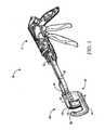
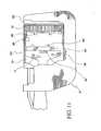
- the linear surgical stapler 20has a handle 21 at a first proximal end and an end effector 80 at an opposite distal end.
- the end effector 80is curved in accordance with a preferred embodiment of the present invention.
- Right and left hand structural plates(often called “handle plates") 34, 35, respectively, connect the handle 21 to the end effector 80 of the instrument (the left hand handle plate is not shown in Figure 1 ).
- the handle 21has a right hand shroud 22 coupled to a left hand shroud (the left hand shroud is not shown in Figure 1 ).
- the handle 21also has a body portion 23 to grip and maneuver the linear surgical stapler 20 (see Figures 2 to 5 ).
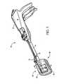
- the end effector 80is a surgical fastening assembly that includes a cartridge module 120 and a C-shaped supporting structure 81.
- the term C-shapedis used throughout the specification to describe the concave nature of the supporting structure 81 and the cartridge module 120.
- the C-shaped constructionfacilitates enhanced functionality and the use of the term C-shaped in the present specification should be construed to include a variety of concave shapes which would similarly enhance the functionality of surgical stapling and cutting instruments.
- a C-shaped constructionis contemplated in accordance with a preferred embodiment of the present invention, those skilled in the art will appreciate the supporting structure may take various shapes without departing from the scope of the present invention.
- the distal end 30 of a closure member 28is disposed to receive the cartridge module 120.
- the end effector 80also includes a safety lockout mechanism 180 (best seen in Figures 6 to 8 ) for preventing the firing of a previously fired cartridge module 120.
- the cartridge module 120contains a cartridge housing 121 coupled to an anvil 122.
- the cartridge module 120also includes a retaining pin 125, a knife 126, a removable retainer 160, a tissue contacting surface 127 which displays a plurality of staple-containing slots 128 in staggered formation in one or more rows (that is, staple lines) on either side of the knife 126.
- Staples(not shown) are fired from the cartridge housing 121 against staple-forming surface 129 of the anvil 122 that faces the tissue-contacting surface 127 of the cartridge housing 121.
- the present linear surgical stapler 20is designed as a multiple firing device with a replaceable cartridge module 120.
- many of the underlying concepts of the present inventionmay be equally applied in single firing devices without departing from the scope of the present invention.
- operation components other than the lockout mechanismare disclosed in commonly owned U.S. Patent No. 11/014,910 , entitled “CURVED CUTTER STAPLER SHAPED FOR MALE PELVIS", filed 12/20/2004.
- the cartridge module 120is provided with a lock tab 182 that interferes with a slide bar 184 positioned at the distal end of the firing bar 43, moving the slide bar 184 rotationally so that tabs 186 on the slide bar 184 are positioned in line with tabs 188 on the knife 126 prior to firing.
- the firing bar 43moves the driver 131 and the knife 126 toward the tissue, thus stapling and cutting the predetermined tissue area.
- the firing bar 43moves the lock tab 182 distally to a neutral position in the cartridge module 120.
- the driver 131 and the lock tab 182remain in the distal position in the cartridge module 120.
- the slide bar 184then rotates into its disconnect position by a spring 190 because the lock tab 182 no longer forces it into its firing position.
- the knife 126will be moved proximally by either employing a spring loading mechanism (not shown) which will act to move the knife 126 rearwardly after firing or selectively locking hooks incorporated into the mating tabs of the slide bar and knife. It is contemplated the locking hooks would be similar to those used in linking the knife to the firing bar as disclosed in U.S. Patent Application Serial No. 11/014,895 , entitled "KNIFE RETRACTION ARM FOR A CURVED CUTTER STAPLER".
- knife retractioncould be accomplished by making the timing between slide bar and lock tab such that the tabs on the slide bar can hook into the knife (or vice versa) such that the rotation of the slide bar causes the disengagement of the retraction hooks between the knife and slide bar only after the knife has been retracted enough to prevent the knife from being exposed outside the cartridge.
- the firing bar 43is free to move distally thereafter as it will not engage or actuate either the driver 131 or knife 126. More particularly, the tabs 186 of the slide bar 184 will not move with the firing bar 43 because the tabs 186 of the slide bar 184 rotate into a disconnect position. The driver 131 remains in the forward proximal position.
- the lockout mechanism 180includes a lock tab 182 integrally formed with the cartridge housing 121 of the cartridge module 120.
- the lockout mechanism 180further includes a firing bar 43 having a slide bar 184 with forwardly extending tabs 186, or prongs, aligned with the knife 126 and driver 131 for subsequent contact therewith.
- the slide bar 184is rotationally mounted to the distal end of the firing bar 43 and interacts with the lock tab 182 to control positioning thereof in a manner which will be discussed below in greater detail.
- the lock tab 182is shaped and dimensioned to engage the distal end of the firing bar 43, in particular, the side bar 184, both before and during actuation of the linear surgical stapler 20.
- the lock tab 182engages the slide bar 184 to ensure that the slide bar tabs 186 are properly aligned with knife tabs 188 extending rearwardly from the proximal end of the knife 126.
- the distal end of the firing bar 43which is provided with a forwardly extending slide bar 184 having aligned tabs 186 extending therefrom, contact the knife 126 and driver 131 to move the knife 126 and driver 131 forward into contact with the anvil 122 to form staples between the driver and anvil.
- the slide bar 184 at the distal end of the firing bar 43contacts knife tabs 188 rearwardly extending from the proximal end of the knife 126. It is the alignment of the slide bar tabs 186 with the knife tabs 188 that permits movement of the knife 126 to cut tissue in a desired manner. Movement of the knife 126 to this forward position ultimately results in cutting of the tissue.
- the firing bar 43In addition to moving the knife 126 and driver 131, the firing bar 43 also moves the lock tab 182 forward into alignment with the proximal side of the knife 126. As the firing bar 43 retracts (see Figure 8 ), the cartridge housing 121 structure moves proximally, although the lock tab 182 remains substantially positioned adjacent the proximal end of the knife 126 and ceases to remain in contact with the slide bar 184. Without the lock tab 182 in contact with the slide bar 184, the slide bar 184 rotates to a lock position. In this lock position, the tabs 186 along the slide bar 184 are out of alignment with the knife tabs 188.
- the present lockout mechanismmay be employed in a variety of environments without departing from the scope of the present invention.
- the embodiment described abovecould be constructed solely as a stapler, without a knife and with the tabs formed on the driver.
- a variation of the present lockout mechanismmay be employed in a surgical instrument not including a knife.
- the knifeis removed and the lock tab is formed as part of the driver and driver tabs.
- this embodimentdiscloses a variation of the lock tab structure disclosed above used in conjunction with an apparatus not including a knife, the various components of the two embodiments could certainly be interchanged without departing from the scope of the invention.
- the cartridge module 220is provided with a lock tab 282 that interferes with a slide bar 284 positioned at the distal end of the firing bar 43, moving the slide bar 284 so tabs 286 on the slide bar 284 are positioned in line with tabs 288 on the driver 231 prior to firing.
- the lock tab 282is formed as part of the driver 231 and moves with the driver 231 during approximation and firing.
- the firing bar 43moves the driver 231 toward the tissue, thus stapling the predetermined tissue area.
- the lock tab 282is moved distally with the driver 231 to a neutral position in the cartridge module 220. After the firing transmission assembly is retracted, the driver 231 and the lock tab 282 remain in the distal position in the cartridge module 220. The slide bar 284 then moves into its disconnect position
- the firing bar 43is free to move distally thereafter as it will not engage or actuate the driver 231. More particularly, the driver 231 will not move with the firing bar 43 because the tabs 286 of the slide bar 284 move into a disconnect position out of alignment with the tabs 288 of the driver 231. The driver 231 remains in the forward proximal position apart from the firing bar 43 after firing.
- the lockout mechanism 280includes a lock tab 282 integrally formed with the driver 231.
- the lockout mechanism 280further includes a firing bar 43 having a slide bar 284 with forwardly extending tabs 286, or prongs, aligned with the driver 231 for subsequent contact therewith.
- the slide bar 284is mounted to the distal end of the firing bar 43 in a manner permitting movement relative thereto and interacts with the lock tab 282 to control positioning thereof in a manner which will be discussed below in greater detail.
- the lock tab 282is shaped and dimensioned to engage the distal end of the firing bar 43, in particular, the side bar 284, both before and during actuation of the linear surgical stapler 20.
- the lock tab 282engages the slide bar 284 to ensure that the slide bar tabs 286 are properly aligned with driver tabs 288 extending rearwardly from the proximal end of the driver 231.
- the distal end of the firing bar 43which is provided with a forwardly extending slide bar 284 having aligned tabs 286 extending therefrom, contacts the driver 231 to move the driver 231 forward into contact with the anvil 222 to form staples between the driver 231 and anvil 222.
- the slide bar 284 at the distal end of the firing bar 43contacts driver tabs 288 rearwardly extending from the proximal end of the driver 231. It is the alignment of the slide bar tabs 286 with the knife tabs 288 that permits movement of the driver 231 to fire the staples in a desired manner.
- the firing bar 43In addition to moving the driver 231, the firing bar 43 also moves the lock tab 282 forward with the driver 231 to which it is attached. As the firing bar 43 retracts (see Figure 8 ), the lock tab 282 remains substantially positioned adjacent the proximal end of the driver 231 and ceases to remain in contact with the slide bar 284. Without the lock tab 282 in contact with the slide bar 284, the slide bar 284 moves to a lock position. In this lock position, the tabs 286 along the slide bar 284 are out of alignment with the driver tabs 288.
- the firing barcould contact the lock tab attached to the driver and slightly push the driver forward even after the slide bar has moved.
- thismay be remedied in a variety of ways by moving the lock tab out of alignment with the firing bar after actuation thereof or otherwise preventing the firing bar from engaging the lock tab after actuation thereof.
- the devicecould be made such that the firing bar no longer lies transversely relative to the lock tab after firing.
- the present inventionovercomes the deficiency of the prior art in that prior art designs mechanically prevent the firing bar from moving distally. As such, and unlike prior art lockout systems which require the device to survive high stress if the user should try to defeat the lockout mechanism, the present lockout mechanism disengages the firing mechanism altogether removing any force transmission that would require the device to survive high loads, that is, the firing bar is entirely disconnected from the driver and/or knife after firing thereof. This allows for a wider range of materials that could be used to produce the device and structures that are less bulky as the device does not have to survive high lockout loads. This would allow for easier manufacturability and cost savings while giving the user a more ergonomically compatible device.
- the present lockout mechanismprovides clear feedback that the lockout mechanism has been activated and may, therefore, not be confused with a jammed system; that is, after the system is fired the firing bar moves freely in a manner which is clearly indicative of a fired system and could not be confused with a jammed system.
Landscapes
- Health & Medical Sciences (AREA)
- Life Sciences & Earth Sciences (AREA)
- Surgery (AREA)
- Heart & Thoracic Surgery (AREA)
- Engineering & Computer Science (AREA)
- Biomedical Technology (AREA)
- Nuclear Medicine, Radiotherapy & Molecular Imaging (AREA)
- Medical Informatics (AREA)
- Molecular Biology (AREA)
- Animal Behavior & Ethology (AREA)
- General Health & Medical Sciences (AREA)
- Public Health (AREA)
- Veterinary Medicine (AREA)
- Surgical Instruments (AREA)
Description
- The present invention relates to surgical stapling and cutting instruments adapted for use in the diagnosis and therapy of pathologies treated by stapled resection. More particularly, the invention relates to a lockout mechanism for utilization in conjunction with surgical stapling and cutting instruments.
- Surgical stapling and cutting instruments are commonly utilized in the diagnosis and treatment of pathologies treated by stapled resection. Surgical stapling and cutting instruments provide a mechanism to extend the transluminal exploitation of mechanical suturing devices introduced via the anal canal, mouth, stomach and service accesses. Although surgical stapling and cutting instruments are most commonly utilized with rectal pathologies, surgical stapling and cutting instruments may be used in a variety of environments.
- Over time, surgical stapling and cutting instruments have been developed. These instruments generally include a support frame, an anvil attached to the support frame and a cartridge housing carrying a plurality of staples. The instruments also include a driver within the cartridge housing which pushes all of the staples out simultaneously into the anvil to form the staples into a generally B-shape, suturing tissue together. In addition, these instruments include approximation mechanisms that allow for the cartridge housing and anvil to move relative to each other to accept tissue therebetween. Finally, the instruments include a firing mechanism for moving the driver forward to form the staples against the anvil.
- In addition to the basic components of the stapling and cutting instruments, these products need a lockout mechanism permitting activation and/or deactivation of the approximation means such that the cartridge module may be utilized as a clamp when needed during an emergency. However, the lockout mechanism is designed such that the firing mechanism only works for a cartridge module that has not been previously used.
- Current surgical stapling instruments include a firing bar lockout that is activated by the driver. When a new cartridge module is loaded into the instrument, the location of the driver, as it relates to the cartridge module in the instrument, interferes with the lockout arm in a way so as to let the instrument fire staples. After the instrument fires staples, the location of the driver moves distally in a way that it no longer interferes with the lockout arm. The lockout arm moves to a position that now interferes with the firing bar, but prevents the firing bar from moving distally. However, prior art lockout mechanism do not provide a clear indication that the instrument has been previously fired. As such, prior lockout mechanism may be simply confused with an instrument that has been jammed.
- In addition, prior lockout systems require the device to survive high stress if the user should try to defeat the lockout mechanism. As will be discussed below in greater detail, the present lockout mechanism disengages the firing mechanism altogether removing any force transmission that would require the device to survive high loads.
US5470008 discloses a surgical stapler having a lockout mechanism comprising a movable barrier plate within the cartridge housing. The barner plate allows the firing bar to pass through a central opening of the plate and to push a staple driver to fire the staples. After firing, the firing bar is retracted and the barrier plate moves to block the firing bar from re-entry into the cartridge housing.US5413267 discloses a surgical stapler with spent cartridge sensing and lockout means. The stapler has a lockout mechanism comprising a pin which extrudes from its embedded position within the end effector frame to its lock position to block the firing bar from contact with the staple driver within the cartridge driver after firing and retraction of the firing bar.- As such, a need exists for an improved lockout mechanism that provides a clear indication that the lockout mechanism has been activated and overcomes the other shortcomings of prior art lockout mechanisms. The present invention provides such a lockout mechanism.
- The present invention provides a surgical stapler adapted for applying a plurality of surgical fasteners to body tissue as claimed in appended claim 1. Further preferred embodiments are specified in the remaining appended claims. The surgical stapler includes an anvil structure and a cartridge housing containing a plurality of surgical fasteners and a knife. The cartridge housing and anvil structure are relatively movable between a first spaced apart position and a second position in close approximation with one another. A firing mechanism is associated with the cartridge housing for ejecting the surgical fasteners from the cartridge housing to be driven against the anvil structure. The firing mechanism includes a slide bar at its distal end adjacent the cartridge housing. A lockout mechanism interacts with the cartridge housing for selective activation and deactivation. The lockout mechanism includes a lock tab that interferes with the slide bar of the firing mechanism moving the slide bar such that tabs on the slide bar move out of alignment with tabs on the knife during firing of the linear surgical stapler to prevent subsequent firing of the linear surgical stapler.
- It is also an object of the present invention to provide a surgical stapler wherein the lock tab rotationally moves the slide bar.
- It is another object of the present invention to provide a surgical stapler wherein during firing of the linear surgical stapler the firing mechanism moves the lock tab distally to a neutral position in the cartridge module.
- It is a further object of the present invention to provide a surgical stapler wherein after the lock tab is moved distally the firing mechanism is retracted and a knife driver and the lock tab remain in the distal position in the cartridge module.
- It is also another object of the present invention to provide a surgical stapler wherein retraction of the firing mechanism causes the knife and slide bar to be moved proximally away from the lock tab, and the slide bar rotates into its disconnect position.
- It is yet another object of the present invention to provide a surgical stapler wherein the slide bar is spring biased.
- It is a further object of the present invention to provide a surgical stapler wherein the lock tab is integrally formed with a cartridge housing of the cartridge module.
- It is still a further object of the present invention to provide a surgical stapler wherein prior to actuation of the firing mechanism the slide bar includes distally extending prongs aligned with the knife and knife driver for subsequent contact therewith.
- It is also an object of the present invention to provide a surgical stapler wherein prior to actuation of the firing mechanism the lock tab engages the slide bar to ensure that the prongs are properly aligned with knife tabs extending proximally from the proximal end of the knife.
- Other objects and advantages of the present invention will become apparent from the following detailed description when viewed in conjunction with the accompanying drawings, which set forth certain embodiments of the invention.
Figure 1 is a perspective view of the linear surgical stapler in accordance with the present invention.Figure 2 is perspective view of the linear surgical stapler with the cartridge module removed.Figure 3 is a perspective view of the linear surgical stapler with the cartridge housing moved to an intermediate position.Figure 4 is a perspective view of the linear surgical stapler with the cartridge housing moved to a closed position.Figure 5 is a perspective view of the linear surgical stapler with the firing trigger in a firing position.Figures 6 through 8 show the various steps involved in the actuation of the present linear surgical stapler.Figures 9 through 11 show the various steps involved in the actuation of the present linear surgical stapler in accordance with an alternate embodiment thereof.- The detailed embodiments of the present invention are disclosed herein. It should be understood, however, that the disclosed embodiments are merely exemplary of the invention, which may be embodied in various forms. Therefore, the details disclosed herein are not to be interpreted as limiting, but merely as the basis for the claims and as a basis for teaching one skilled in the art how to make and/or use the invention.
- With reference to the various figures, a
surgical instrument 20 adapted for applying a plurality of surgical fasteners to body tissue is disclosed. Thesurgical instrument 20 includes ananvil 122 and acartridge housing 121 containing a plurality of surgical fasteners. The cartridge housing 121 andanvil 122 are relatively movable between a first spaced apart position and a second position in close approximation with one another. A firing mechanism is associated with thecartridge housing 121 for ejecting the surgical fasteners from thecartridge housing 121 to be driven against theanvil 122. Alockout mechanism 180 interacts with thecartridge housing 121 for selective activation and deactivation of the closing mechanism. Alockout mechanism 180 interacts with thecartridge housing 121 for selective activation and deactivation. Thelockout mechanism 180 includes alock tab 182 that interferes with aslide bar 184 of the firing mechanism moving theslide bar 184 rotationally such thattabs 186 on theslide bar 184 move out of alignment withtabs 188 on theknife 126 during firing of the linear surgical stapler to prevent subsequent firing of the linear surgical stapler. - Referring to
Figure 1 in combination withFigures 2 to 5 , there is shown a surgical stapling and cutting instrument, in particular, a linearsurgical stapler 20 which is designed to staple and cut tissue. The linearsurgical stapler 20 has ahandle 21 at a first proximal end and anend effector 80 at an opposite distal end. Theend effector 80 is curved in accordance with a preferred embodiment of the present invention. Right and left hand structural plates (often called "handle plates") 34, 35, respectively, connect thehandle 21 to theend effector 80 of the instrument (the left hand handle plate is not shown inFigure 1 ). Thehandle 21 has a right hand shroud 22 coupled to a left hand shroud (the left hand shroud is not shown inFigure 1 ). Thehandle 21 also has abody portion 23 to grip and maneuver the linear surgical stapler 20 (seeFigures 2 to 5 ). - The
end effector 80 is a surgical fastening assembly that includes acartridge module 120 and a C-shaped supportingstructure 81. The term C-shaped is used throughout the specification to describe the concave nature of the supportingstructure 81 and thecartridge module 120. The C-shaped construction facilitates enhanced functionality and the use of the term C-shaped in the present specification should be construed to include a variety of concave shapes which would similarly enhance the functionality of surgical stapling and cutting instruments. Although a C-shaped construction is contemplated in accordance with a preferred embodiment of the present invention, those skilled in the art will appreciate the supporting structure may take various shapes without departing from the scope of the present invention. Thedistal end 30 of aclosure member 28 is disposed to receive thecartridge module 120. Theend effector 80 also includes a safety lockout mechanism 180 (best seen inFigures 6 to 8 ) for preventing the firing of a previously firedcartridge module 120. Thecartridge module 120 contains acartridge housing 121 coupled to ananvil 122. Thecartridge module 120 also includes a retainingpin 125, aknife 126, aremovable retainer 160, atissue contacting surface 127 which displays a plurality of staple-containingslots 128 in staggered formation in one or more rows (that is, staple lines) on either side of theknife 126. Staples (not shown) are fired from thecartridge housing 121 against staple-formingsurface 129 of theanvil 122 that faces the tissue-contactingsurface 127 of thecartridge housing 121. - As will become apparent based upon the following disclosure, the present linear
surgical stapler 20 is designed as a multiple firing device with areplaceable cartridge module 120. However, it should be understood that many of the underlying concepts of the present invention may be equally applied in single firing devices without departing from the scope of the present invention. With this in mind, operation components other than the lockout mechanism are disclosed in commonly ownedU.S. Patent No. 11/014,910 - Referring to
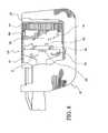
Figures 6 though 8 (cut away view into cartridge and support structure), the components of the fireddevice lockout mechanism 180 will now be described. In accordance with a preferred embodiment of the present invention, thecartridge module 120 is provided with alock tab 182 that interferes with aslide bar 184 positioned at the distal end of the firingbar 43, moving theslide bar 184 rotationally so thattabs 186 on theslide bar 184 are positioned in line withtabs 188 on theknife 126 prior to firing. - When the firing transmission assembly is moved distally, the firing
bar 43 moves thedriver 131 and theknife 126 toward the tissue, thus stapling and cutting the predetermined tissue area. During firing, the firingbar 43 moves thelock tab 182 distally to a neutral position in thecartridge module 120. After the firing transmission assembly is retracted, thedriver 131 and thelock tab 182 remain in the distal position in thecartridge module 120. Theslide bar 184 then rotates into its disconnect position by aspring 190 because thelock tab 182 no longer forces it into its firing position. - It is contemplated the
knife 126 will be moved proximally by either employing a spring loading mechanism (not shown) which will act to move theknife 126 rearwardly after firing or selectively locking hooks incorporated into the mating tabs of the slide bar and knife. It is contemplated the locking hooks would be similar to those used in linking the knife to the firing bar as disclosed inU.S. Patent Application Serial No. 11/014,895 , entitled "KNIFE RETRACTION ARM FOR A CURVED CUTTER STAPLER". - It is further contemplated knife retraction could be accomplished by making the timing between slide bar and lock tab such that the tabs on the slide bar can hook into the knife (or vice versa) such that the rotation of the slide bar causes the disengagement of the retraction hooks between the knife and slide bar only after the knife has been retracted enough to prevent the knife from being exposed outside the cartridge.
- The firing
bar 43 is free to move distally thereafter as it will not engage or actuate either thedriver 131 orknife 126. More particularly, thetabs 186 of theslide bar 184 will not move with the firingbar 43 because thetabs 186 of theslide bar 184 rotate into a disconnect position. Thedriver 131 remains in the forward proximal position. - More particularly, and with reference to
Figures 6 to 8 , thelockout mechanism 180 includes alock tab 182 integrally formed with thecartridge housing 121 of thecartridge module 120. Thelockout mechanism 180 further includes a firingbar 43 having aslide bar 184 with forwardly extendingtabs 186, or prongs, aligned with theknife 126 anddriver 131 for subsequent contact therewith. Theslide bar 184 is rotationally mounted to the distal end of the firingbar 43 and interacts with thelock tab 182 to control positioning thereof in a manner which will be discussed below in greater detail. As such, thelock tab 182 is shaped and dimensioned to engage the distal end of the firingbar 43, in particular, theside bar 184, both before and during actuation of the linearsurgical stapler 20. - Prior to actuation of the firing transmission assembly, and with reference to
Figure 6 , thelock tab 182 engages theslide bar 184 to ensure that theslide bar tabs 186 are properly aligned withknife tabs 188 extending rearwardly from the proximal end of theknife 126. Upon actuation of the firing transmission assembly and forward movement of the firing bar 43 (seeFigure 7 ), the distal end of the firingbar 43, which is provided with a forwardly extendingslide bar 184 having alignedtabs 186 extending therefrom, contact theknife 126 anddriver 131 to move theknife 126 anddriver 131 forward into contact with theanvil 122 to form staples between the driver and anvil. Specifically, theslide bar 184 at the distal end of the firingbar 43contacts knife tabs 188 rearwardly extending from the proximal end of theknife 126. It is the alignment of theslide bar tabs 186 with theknife tabs 188 that permits movement of theknife 126 to cut tissue in a desired manner. Movement of theknife 126 to this forward position ultimately results in cutting of the tissue. - In addition to moving the
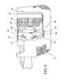
knife 126 anddriver 131, the firingbar 43 also moves thelock tab 182 forward into alignment with the proximal side of theknife 126. As the firingbar 43 retracts (seeFigure 8 ), thecartridge housing 121 structure moves proximally, although thelock tab 182 remains substantially positioned adjacent the proximal end of theknife 126 and ceases to remain in contact with theslide bar 184. Without thelock tab 182 in contact with theslide bar 184, theslide bar 184 rotates to a lock position. In this lock position, thetabs 186 along theslide bar 184 are out of alignment with theknife tabs 188. In this position, although the firingbar 43 may still be moved distally toward theknife 126 anddriver 131, thetabs 186 of theslide bar 184 will not contact theknife tabs 188 and the firingbar 43 is, therefore, unable to move theknife 126 forward toward theanvil 122. - As those skilled in the art will certainly appreciate, the present lockout mechanism may be employed in a variety of environments without departing from the scope of the present invention. For example, the embodiment described above could be constructed solely as a stapler, without a knife and with the tabs formed on the driver.
- In addition, and with reference to
Figures 9 ,10 and11 , a variation of the present lockout mechanism may be employed in a surgical instrument not including a knife. In accordance with this embodiment, the knife is removed and the lock tab is formed as part of the driver and driver tabs. Although this embodiment discloses a variation of the lock tab structure disclosed above used in conjunction with an apparatus not including a knife, the various components of the two embodiments could certainly be interchanged without departing from the scope of the invention. - With reference to
Figures 9 ,10 and11 , the components of this alternate embodiment of the fireddevice lockout mechanism 280 will now be described. In accordance with a preferred embodiment of the present invention, thecartridge module 220 is provided with alock tab 282 that interferes with aslide bar 284 positioned at the distal end of the firingbar 43, moving theslide bar 284 sotabs 286 on theslide bar 284 are positioned in line withtabs 288 on thedriver 231 prior to firing. In fact, thelock tab 282 is formed as part of thedriver 231 and moves with thedriver 231 during approximation and firing. - When the firing transmission assembly is moved distally, the firing
bar 43 moves thedriver 231 toward the tissue, thus stapling the predetermined tissue area. During approximation and firing, thelock tab 282 is moved distally with thedriver 231 to a neutral position in thecartridge module 220. After the firing transmission assembly is retracted, thedriver 231 and thelock tab 282 remain in the distal position in thecartridge module 220. Theslide bar 284 then moves into its disconnect position - The firing
bar 43 is free to move distally thereafter as it will not engage or actuate thedriver 231. More particularly, thedriver 231 will not move with the firingbar 43 because thetabs 286 of theslide bar 284 move into a disconnect position out of alignment with thetabs 288 of thedriver 231. Thedriver 231 remains in the forward proximal position apart from the firingbar 43 after firing. - More particularly, and with reference to
Figures 6 to 8 , thelockout mechanism 280 includes alock tab 282 integrally formed with thedriver 231. Thelockout mechanism 280 further includes a firingbar 43 having aslide bar 284 with forwardly extendingtabs 286, or prongs, aligned with thedriver 231 for subsequent contact therewith. Theslide bar 284 is mounted to the distal end of the firingbar 43 in a manner permitting movement relative thereto and interacts with thelock tab 282 to control positioning thereof in a manner which will be discussed below in greater detail. Thelock tab 282 is shaped and dimensioned to engage the distal end of the firingbar 43, in particular, theside bar 284, both before and during actuation of the linearsurgical stapler 20. - Prior to actuation of the firing transmission assembly, and with reference to
Figure 6 , thelock tab 282 engages theslide bar 284 to ensure that theslide bar tabs 286 are properly aligned withdriver tabs 288 extending rearwardly from the proximal end of thedriver 231. Upon actuation of the firing transmission assembly and forward movement of the firing bar 43 (seeFigure 7 ), the distal end of the firingbar 43, which is provided with a forwardly extendingslide bar 284 having alignedtabs 286 extending therefrom, contacts thedriver 231 to move thedriver 231 forward into contact with theanvil 222 to form staples between thedriver 231 andanvil 222. Specifically, theslide bar 284 at the distal end of the firingbar 43contacts driver tabs 288 rearwardly extending from the proximal end of thedriver 231. It is the alignment of theslide bar tabs 286 with theknife tabs 288 that permits movement of thedriver 231 to fire the staples in a desired manner. - In addition to moving the
driver 231, the firingbar 43 also moves thelock tab 282 forward with thedriver 231 to which it is attached. As the firingbar 43 retracts (seeFigure 8 ), thelock tab 282 remains substantially positioned adjacent the proximal end of thedriver 231 and ceases to remain in contact with theslide bar 284. Without thelock tab 282 in contact with theslide bar 284, theslide bar 284 moves to a lock position. In this lock position, thetabs 286 along theslide bar 284 are out of alignment with thedriver tabs 288. In this position, although the firingbar 43 may still be moved distally toward thedriver 231, thetabs 286 of theslide bar 284 will not contact thedriver tabs 288 and the firingbar 43 is, therefore, unable to move thedriver 231 forward toward theanvil 122. - As those skilled in the art may appreciate, it is possible the firing bar could contact the lock tab attached to the driver and slightly push the driver forward even after the slide bar has moved. However, this may be remedied in a variety of ways by moving the lock tab out of alignment with the firing bar after actuation thereof or otherwise preventing the firing bar from engaging the lock tab after actuation thereof. For example, the device could be made such that the firing bar no longer lies transversely relative to the lock tab after firing.
- The present invention overcomes the deficiency of the prior art in that prior art designs mechanically prevent the firing bar from moving distally. As such, and unlike prior art lockout systems which require the device to survive high stress if the user should try to defeat the lockout mechanism, the present lockout mechanism disengages the firing mechanism altogether removing any force transmission that would require the device to survive high loads, that is, the firing bar is entirely disconnected from the driver and/or knife after firing thereof. This allows for a wider range of materials that could be used to produce the device and structures that are less bulky as the device does not have to survive high lockout loads. This would allow for easier manufacturability and cost savings while giving the user a more ergonomically compatible device. In addition, the present lockout mechanism provides clear feedback that the lockout mechanism has been activated and may, therefore, not be confused with a jammed system; that is, after the system is fired the firing bar moves freely in a manner which is clearly indicative of a fired system and could not be confused with a jammed system.
- While the preferred embodiments have been shown and described, it will be understood that there is no intent to limit the invention by such disclosure, but rather, is intended to cover all modifications and alternate constructions falling within the scope of the invention.
Claims (10)
- A surgical stapler (20) adapted for applying a plurality of surgical fasteners to body tissue, the surgical stapler comprising:an anvil structure (122, 222);a cartridge housing (121, 221) including at least one driving component (126, 231) for the application of surgical fasteners housed therein;a firing mechanism; anda lockout mechanism (180, 280) for activation and deactivation of the firing mechanism by disconnecting the firing mechanism from the driving component housed within the cartridge housing,wherein the cartridge housing contains a plurality of surgical fasteners, the cartridge housing and anvil structure being relatively movable between a first spaced apart position and a second position in close approximation with one another;wherein the firing mechanism is adapted to cooperate with the driving component housed within the cartridge housing for ejecting the surgical fasteners from the cartridge housing to be driven against the anvil structure;
characterized in that,
the firing mechanism comprises a slide bar (184, 284) at its distal end and the lockout mechanism includes a lock tab (182, 282) that interferes with the slide bar, wherein the lock tab is adapted to move distally with the slide bar during the firing of the surgical stapler in which the slide bar can be moved into connection with the driving component, and adapted to disengage the slide bar such that the slide bar moves into a disconnect position in which the slide bar is prevented from connection with the driving component by the lock tab to prevent subsequent firing of the surgical stapler. - The surgical stapler according to claim 1, wherein the cartridge housing (121) contains a knife (126).
- The surgical stapler according to claim 2, wherein the lock tab (182) is adapted to engage the slide bar (184) of the firing mechanism to ensure that prior to actuation of firing mechanism tabs (186) on the slide bar are properly aligned with tabs (188) on the knife, moving the slide bar such that the tabs (186) on the slide bar move out of alignment with the tabs (188) on the knife during firing of the surgical stapler to disconnect the firing mechanism from the knife and prevent subsequent firing of the surgical stapler.
- The surgical stapler according to claim 3, wherein after the lock tab is moved distally the firing mechanism is retracted, and the lock tab remains in the distal position in the cartridge housing.
- The surgical stapler according to claim 4, wherein retraction of the firing mechanism causes the slide bar to be moved proximally away from the lock tab, and the slide bar moves into its disconnect position.
- The surgical stapler according to claim 1, wherein the cartridge housing (221) contains a driver (231) for ejecting the surgical fasteners from the cartridge housing against the anvil structure.
- The surgical stapler according to claim 6, wherein the lock tab (282) is adapted to engage the slide bar (284) of the firing mechanism to ensure that prior to actuation of the firing mechanism tabs (286) on the slide bar are properly aligned with tabs (288) on the driver, moving the slide bar such that the tabs (286) on the slide bar move out of alignment with the tabs (288) on the driver during firing of the surgical stapler to disconnect the firing mechanism from the driver and prevent subsequent firing of the surgical stapler.
- The surgical stapler according to claim 7, wherein after the lock tab (282) is moved distally the firing mechanism is retracted, and the lock tab remains in the distal position in the cartridge housing.
- The surgical stapler according to claim 3 or 7, wherein the tabs on the slide bar and on the driving component are prongs.
- The surgical stapler according to any preceding claim, wherein the slide bar is rotationally mounted a distal end of a firing bar (43).
Priority Applications (1)
| Application Number | Priority Date | Filing Date | Title |
|---|---|---|---|
| PL06254312TPL1754446T3 (en) | 2005-08-18 | 2006-08-17 | Fired device lockout for a curved cutter stapler with a free moving trigger |
Applications Claiming Priority (1)
| Application Number | Priority Date | Filing Date | Title |
|---|---|---|---|
| US11/206,298US7886953B2 (en) | 2005-08-18 | 2005-08-18 | Fired device lockout for a curved cutter stapler with a free moving trigger |
Publications (3)
| Publication Number | Publication Date |
|---|---|
| EP1754446A2 EP1754446A2 (en) | 2007-02-21 |
| EP1754446A3 EP1754446A3 (en) | 2008-11-05 |
| EP1754446B1true EP1754446B1 (en) | 2015-09-16 |
Family
ID=37499746
Family Applications (1)
| Application Number | Title | Priority Date | Filing Date |
|---|---|---|---|
| EP06254312.9AActiveEP1754446B1 (en) | 2005-08-18 | 2006-08-17 | Fired device lockout for a curved cutter stapler with a free moving trigger |
Country Status (9)
| Country | Link |
|---|---|
| US (1) | US7886953B2 (en) |
| EP (1) | EP1754446B1 (en) |
| JP (1) | JP5000232B2 (en) |
| CN (1) | CN1919149B (en) |
| AU (1) | AU2006203409B2 (en) |
| BR (1) | BRPI0603366B8 (en) |
| CA (1) | CA2556381C (en) |
| ES (1) | ES2556246T3 (en) |
| PL (1) | PL1754446T3 (en) |
Families Citing this family (90)
| Publication number | Priority date | Publication date | Assignee | Title |
|---|---|---|---|---|
| US7464847B2 (en) | 2005-06-03 | 2008-12-16 | Tyco Healthcare Group Lp | Surgical stapler with timer and feedback display |
| US10285694B2 (en) | 2001-10-20 | 2019-05-14 | Covidien Lp | Surgical stapler with timer and feedback display |
| US20090090763A1 (en)* | 2007-10-05 | 2009-04-09 | Tyco Healthcare Group Lp | Powered surgical stapling device |
| CA2609970C (en) | 2005-06-03 | 2014-08-12 | Tyco Healthcare Group Lp | Battery powered surgical instrument |
| US11291443B2 (en) | 2005-06-03 | 2022-04-05 | Covidien Lp | Surgical stapler with timer and feedback display |
| US7431188B1 (en) | 2007-03-15 | 2008-10-07 | Tyco Healthcare Group Lp | Surgical stapling apparatus with powered articulation |
| US7950560B2 (en) | 2007-04-13 | 2011-05-31 | Tyco Healthcare Group Lp | Powered surgical instrument |
| US20080255413A1 (en) | 2007-04-13 | 2008-10-16 | Michael Zemlok | Powered surgical instrument |
| US8800837B2 (en) | 2007-04-13 | 2014-08-12 | Covidien Lp | Powered surgical instrument |
| US11259801B2 (en) | 2007-04-13 | 2022-03-01 | Covidien Lp | Powered surgical instrument |
| US7823760B2 (en) | 2007-05-01 | 2010-11-02 | Tyco Healthcare Group Lp | Powered surgical stapling device platform |
| US7931660B2 (en) | 2007-05-10 | 2011-04-26 | Tyco Healthcare Group Lp | Powered tacker instrument |
| US8517241B2 (en) | 2010-04-16 | 2013-08-27 | Covidien Lp | Hand-held surgical devices |
| US8967443B2 (en) | 2007-10-05 | 2015-03-03 | Covidien Lp | Method and apparatus for determining parameters of linear motion in a surgical instrument |
| US8960520B2 (en) | 2007-10-05 | 2015-02-24 | Covidien Lp | Method and apparatus for determining parameters of linear motion in a surgical instrument |
| US7922063B2 (en) | 2007-10-31 | 2011-04-12 | Tyco Healthcare Group, Lp | Powered surgical instrument |
| US7819298B2 (en)* | 2008-02-14 | 2010-10-26 | Ethicon Endo-Surgery, Inc. | Surgical stapling apparatus with control features operable with one hand |
| US7988028B2 (en) | 2008-09-23 | 2011-08-02 | Tyco Healthcare Group Lp | Surgical instrument having an asymmetric dynamic clamping member |
| US8360298B2 (en) | 2008-09-23 | 2013-01-29 | Covidien Lp | Surgical instrument and loading unit for use therewith |
| US8393516B2 (en)* | 2009-02-26 | 2013-03-12 | Covidien Lp | Surgical stapling apparatus with curved cartridge and anvil assemblies |
| US8821514B2 (en)* | 2009-06-08 | 2014-09-02 | Covidien Lp | Powered tack applier |
| US8225979B2 (en) | 2009-10-30 | 2012-07-24 | Tyco Healthcare Group Lp | Locking shipping wedge |
| US8360296B2 (en) | 2010-09-09 | 2013-01-29 | Ethicon Endo-Surgery, Inc. | Surgical stapling head assembly with firing lockout for a surgical stapler |
| US8899461B2 (en) | 2010-10-01 | 2014-12-02 | Covidien Lp | Tissue stop for surgical instrument |
| US8444038B2 (en) | 2010-10-01 | 2013-05-21 | Covidien Lp | Tissue stop for surgical instrument |
| US9211122B2 (en) | 2011-03-14 | 2015-12-15 | Ethicon Endo-Surgery, Inc. | Surgical access devices with anvil introduction and specimen retrieval structures |
| US8397972B2 (en) | 2011-03-18 | 2013-03-19 | Covidien Lp | Shipping wedge with lockout |
| CN102835983B (en)* | 2011-06-21 | 2016-08-17 | 伊西康内外科公司 | Linear staplers |
| CN103083053A (en)* | 2011-11-07 | 2013-05-08 | 苏州天臣国际医疗科技有限公司 | Nail head assembly of stitching device and sewing cutting device |
| CN102551827B (en)* | 2012-02-03 | 2014-02-05 | 北京中法派尔特医疗设备有限公司 | Stitching instrument with cutter |
| US9113881B2 (en) | 2012-03-16 | 2015-08-25 | Covidien Lp | Travel clip for surgical staple cartridge |
| US8518055B1 (en) | 2012-05-11 | 2013-08-27 | Ethicon, Inc. | Applicator instruments for dispensing surgical fasteners during open repair procedures |
| US9364228B2 (en)* | 2012-05-11 | 2016-06-14 | Ethicon, Llc | Applicator instruments having distal end caps for facilitating the accurate placement of surgical fasteners during open repair procedures |
| US10575716B2 (en) | 2012-05-11 | 2020-03-03 | Ethicon Llc | Applicator instruments with imaging systems for dispensing surgical fasteners during open repair procedures |
| US10561432B2 (en) | 2013-03-05 | 2020-02-18 | Covidien Lp | Pivoting screw for use with a pair of jaw members of a surgical instrument |
| USD717431S1 (en) | 2013-03-05 | 2014-11-11 | Ethicon, Inc. | Applicator instrument |
| USD707820S1 (en) | 2013-03-05 | 2014-06-24 | Ethicon, Inc. | Contoured tip |
| US9649109B2 (en) | 2013-03-14 | 2017-05-16 | C.R. Bard, Inc. | Surgical instrument with an actuation lockout |
| US9707005B2 (en) | 2014-02-14 | 2017-07-18 | Ethicon Llc | Lockout mechanisms for surgical devices |
| US10335147B2 (en)* | 2014-06-25 | 2019-07-02 | Ethicon Llc | Method of using lockout features for surgical stapler cartridge |
| US10702269B2 (en) | 2014-12-25 | 2020-07-07 | Covidien Lp | Surgical stapling devices |
| US10092290B2 (en) | 2015-03-17 | 2018-10-09 | Covidien Lp | Surgical instrument, loading unit for use therewith and related methods |
| US10159471B2 (en) | 2015-05-13 | 2018-12-25 | C.R. Bard, Inc. | Actuation lockout for a surgical instrument |
| US10405858B2 (en) | 2015-06-30 | 2019-09-10 | C.R. Bard, Inc. | Actuation lockout for a surgical instrument |
| US10420552B2 (en) | 2016-04-01 | 2019-09-24 | Ethicon Llc | Surgical stapling system configured to provide selective cutting of tissue |
| US11284890B2 (en) | 2016-04-01 | 2022-03-29 | Cilag Gmbh International | Circular stapling system comprising an incisable tissue support |
| JP7010838B2 (en) | 2016-04-01 | 2022-01-26 | エシコン エルエルシー | Surgical staple fasteners |
| JP6957499B2 (en)* | 2016-04-01 | 2021-11-02 | エシコン エルエルシーEthicon LLC | Surgical staple system with used cartridge lockout |
| US10413297B2 (en)* | 2016-04-01 | 2019-09-17 | Ethicon Llc | Surgical stapling system configured to apply annular rows of staples having different heights |
| US10531874B2 (en) | 2016-04-01 | 2020-01-14 | Ethicon Llc | Surgical cutting and stapling end effector with anvil concentric drive member |
| AU2017258826A1 (en) | 2016-12-02 | 2018-06-21 | Covidien Lp | Surgical stapling instrument with curved end effector |
| MX2019007295A (en)* | 2016-12-21 | 2019-10-15 | Ethicon Llc | Surgical instrument system comprising an end effector lockout and a firing assembly lockout. |
| US11311295B2 (en) | 2017-05-15 | 2022-04-26 | Covidien Lp | Adaptive powered stapling algorithm with calibration factor |
| US11207066B2 (en) | 2017-10-30 | 2021-12-28 | Covidien Lp | Apparatus for endoscopic procedures |
| US12185949B2 (en) | 2017-10-30 | 2025-01-07 | Covidien Lp | Apparatus for endoscopic procedures |
| US10987104B2 (en) | 2017-10-30 | 2021-04-27 | Covidien Lp | Apparatus for endoscopic procedures |
| US10993714B2 (en) | 2017-11-28 | 2021-05-04 | Covidien Lp | Surgical stapling instrument and associated trigger mechanisms |
| US10945730B2 (en) | 2018-06-25 | 2021-03-16 | Covidien Lp | Stapling device with selectively advanceable alignment pin |
| US11497490B2 (en) | 2018-07-09 | 2022-11-15 | Covidien Lp | Powered surgical devices including predictive motor control |
| US12137902B2 (en) | 2018-07-25 | 2024-11-12 | Covidien Lp | Adaptive anti-twitch algorithm for powered surgical devices |
| US11197734B2 (en) | 2018-10-30 | 2021-12-14 | Covidien Lp | Load sensing devices for use in surgical instruments |
| US11369372B2 (en) | 2018-11-28 | 2022-06-28 | Covidien Lp | Surgical stapler adapter with flexible cable assembly, flexible fingers, and contact clips |
| US11202635B2 (en) | 2019-02-04 | 2021-12-21 | Covidien Lp | Programmable distal tilt position of end effector for powered surgical devices |
| US11376006B2 (en) | 2019-02-06 | 2022-07-05 | Covidien Lp | End effector force measurement with digital drive circuit |
| US11219461B2 (en) | 2019-03-08 | 2022-01-11 | Covidien Lp | Strain gauge stabilization in a surgical device |
| WO2021022407A1 (en) | 2019-08-02 | 2021-02-11 | Covidien Lp | Surgical stapling device with curved tool assembly |
| CN114727818A (en) | 2019-11-01 | 2022-07-08 | 柯惠有限合伙公司 | Surgical Stapling Device with Blade Lock |
| US11534163B2 (en) | 2019-11-21 | 2022-12-27 | Covidien Lp | Surgical stapling instruments |
| WO2021120046A1 (en) | 2019-12-18 | 2021-06-24 | Covidien Lp | Surgical stapling device with shipping cap |
| WO2021155483A1 (en) | 2020-02-03 | 2021-08-12 | Covidien Lp | Tissue guide for curved end effectors |
| US11458244B2 (en) | 2020-02-07 | 2022-10-04 | Covidien Lp | Irrigating surgical apparatus with positive pressure fluid |
| US11553913B2 (en) | 2020-02-11 | 2023-01-17 | Covidien Lp | Electrically-determining tissue cut with surgical stapling apparatus |
| JP2023524928A (en) | 2020-02-27 | 2023-06-14 | コヴィディエン リミテッド パートナーシップ | Surgical stapling device with reloadable cartridge |
| WO2021168761A1 (en)* | 2020-02-28 | 2021-09-02 | Covidien Lp | Staple cartridge with retractable knife assembly |
| US12029470B2 (en) | 2020-05-21 | 2024-07-09 | Covidien Lp | Simultaneous RF monopolar calibration using a shared return electrode |
| US11744584B2 (en) | 2020-06-09 | 2023-09-05 | Covidien Lp | Alignment pin assembly for surgical stapler |
| CN111700668B (en)* | 2020-06-18 | 2021-03-16 | 苏州贝诺医疗器械有限公司 | Transverse intracavity stitching instrument with compact structure |
| US11622768B2 (en) | 2020-07-13 | 2023-04-11 | Covidien Lp | Methods and structure for confirming proper assembly of powered surgical stapling systems |
| US12193884B2 (en) | 2020-11-17 | 2025-01-14 | Covidien Lp | Contactless force measurement of motor torque in powered surgical device |
| US11653919B2 (en) | 2020-11-24 | 2023-05-23 | Covidien Lp | Stapler line reinforcement continuity |
| US11744580B2 (en) | 2020-11-24 | 2023-09-05 | Covidien Lp | Long stapler reloads with continuous cartridge |
| US12343010B2 (en) | 2020-12-17 | 2025-07-01 | Covidien Lp | Stapling device with curved end effector |
| WO2022178758A1 (en)* | 2021-02-25 | 2022-09-01 | Covidien Lp | Anvil assembly with reduced deflection |
| JP2024511662A (en) | 2021-03-30 | 2024-03-14 | コヴィディエン リミテッド パートナーシップ | Surgical anastomosis device including loading unit alignment indicator |
| US12016556B2 (en) | 2021-05-03 | 2024-06-25 | Covidien Lp | Handheld electromechanical surgical system |
| US11684362B2 (en) | 2021-06-07 | 2023-06-27 | Covidien Lp | Handheld electromechanical surgical system |
| US11771432B2 (en) | 2021-06-29 | 2023-10-03 | Covidien Lp | Stapling and cutting to default values in the event of strain gauge data integrity loss |
| US12268390B2 (en) | 2021-07-19 | 2025-04-08 | Covidien Lp | Stapling device with replaceable cartridge module |
| US12161341B2 (en) | 2021-09-07 | 2024-12-10 | Covidien Lp | Slow speed staple and staple relaxation for stapling optimization |
| US11832823B2 (en) | 2022-02-08 | 2023-12-05 | Covidien Lp | Determination of anvil release during anastomosis |
Family Cites Families (18)
| Publication number | Priority date | Publication date | Assignee | Title |
|---|---|---|---|---|
| US4527724A (en)* | 1983-06-10 | 1985-07-09 | Senmed, Inc. | Disposable linear surgical stapling instrument |
| US4665916A (en)* | 1985-08-09 | 1987-05-19 | United States Surgical Corporation | Surgical stapler apparatus |
| US5116349A (en)* | 1990-05-23 | 1992-05-26 | United States Surgical Corporation | Surgical fastener apparatus |
| CA2055943C (en)* | 1990-12-06 | 2003-09-23 | Daniel P. Rodak | Surgical fastening apparatus with locking mechanism |
| US5413267A (en) | 1991-05-14 | 1995-05-09 | United States Surgical Corporation | Surgical stapler with spent cartridge sensing and lockout means |
| EP0596543B1 (en)* | 1991-05-14 | 1999-08-11 | United States Surgical Corporation | Surgical stapler with spent cartridge sensing and lockout means |
| CA2078794C (en)* | 1991-10-18 | 1998-10-06 | Frank J. Viola | Locking device for an apparatus for applying surgical fasteners |
| US5470008A (en)* | 1993-12-20 | 1995-11-28 | United States Surgical Corporation | Apparatus for applying surgical fasteners |
| WO1995023557A1 (en)* | 1994-03-01 | 1995-09-08 | United States Surgical Corporation | Surgical stapler with anvil sensor and lockout |
| CN1067544C (en)* | 1994-11-14 | 2001-06-27 | 张祖仁 | Suturing device for surgical operation |
| US5632432A (en)* | 1994-12-19 | 1997-05-27 | Ethicon Endo-Surgery, Inc. | Surgical instrument |
| US5735445A (en)* | 1995-03-07 | 1998-04-07 | United States Surgical Corporation | Surgical stapler |
| US5706998A (en)* | 1995-07-17 | 1998-01-13 | United States Surgical Corporation | Surgical stapler with alignment pin locking mechanism |
| US6805273B2 (en)* | 2002-11-04 | 2004-10-19 | Federico Bilotti | Surgical stapling instrument |
| US6817508B1 (en)* | 2000-10-13 | 2004-11-16 | Tyco Healthcare Group, Lp | Surgical stapling device |
| US20050143759A1 (en) | 2003-12-30 | 2005-06-30 | Kelly William D. | Curved cutter stapler shaped for male pelvis |
| US7147139B2 (en)* | 2003-12-30 | 2006-12-12 | Ethicon Endo-Surgery, Inc | Closure plate lockout for a curved cutter stapler |
| US7134587B2 (en)* | 2003-12-30 | 2006-11-14 | Ethicon Endo-Surgery, Inc. | Knife retraction arm for a curved cutter stapler |
- 2005
- 2005-08-18USUS11/206,298patent/US7886953B2/enactiveActive
- 2006
- 2006-08-08AUAU2006203409Apatent/AU2006203409B2/ennot_activeCeased
- 2006-08-16BRBRPI0603366Apatent/BRPI0603366B8/enactiveIP Right Grant
- 2006-08-17EPEP06254312.9Apatent/EP1754446B1/enactiveActive
- 2006-08-17JPJP2006222588Apatent/JP5000232B2/enactiveActive
- 2006-08-17PLPL06254312Tpatent/PL1754446T3/enunknown
- 2006-08-17ESES06254312.9Tpatent/ES2556246T3/enactiveActive
- 2006-08-17CACA2556381Apatent/CA2556381C/ennot_activeExpired - Fee Related
- 2006-08-18CNCN2006101216973Apatent/CN1919149B/enactiveActive
Also Published As
| Publication number | Publication date |
|---|---|
| AU2006203409B2 (en) | 2012-03-22 |
| CA2556381C (en) | 2014-05-13 |
| ES2556246T3 (en) | 2016-01-14 |
| BRPI0603366A (en) | 2007-09-04 |
| JP2007050260A (en) | 2007-03-01 |
| BRPI0603366B8 (en) | 2021-06-22 |
| US7886953B2 (en) | 2011-02-15 |
| US20070039995A1 (en) | 2007-02-22 |
| CA2556381A1 (en) | 2007-02-18 |
| CN1919149B (en) | 2010-08-25 |
| BRPI0603366B1 (en) | 2018-02-14 |
| PL1754446T3 (en) | 2016-03-31 |
| JP5000232B2 (en) | 2012-08-15 |
| EP1754446A3 (en) | 2008-11-05 |
| AU2006203409A1 (en) | 2007-03-08 |
| EP1754446A2 (en) | 2007-02-21 |
| CN1919149A (en) | 2007-02-28 |
Similar Documents
| Publication | Publication Date | Title |
|---|---|---|
| EP1754446B1 (en) | Fired device lockout for a curved cutter stapler with a free moving trigger | |
| EP3545868B1 (en) | Surgical instrument comprising a jaw lockout | |
| EP1749486B1 (en) | Swing gate for device lockout in a curved cutter stapler | |
| US20250160832A1 (en) | Methods for controlling a surgical stapler | |
| US11219453B2 (en) | Surgical stapling devices with cartridge compatible closure and firing lockout arrangements | |
| US11278280B2 (en) | Surgical instrument comprising a jaw closure lockout | |
| MXPA06009444A (en) | Fired device lockout for a curved cutter stapler with a free moving trigger |
Legal Events
| Date | Code | Title | Description |
|---|---|---|---|
| PUAI | Public reference made under article 153(3) epc to a published international application that has entered the european phase | Free format text:ORIGINAL CODE: 0009012 | |
| AK | Designated contracting states | Kind code of ref document:A2 Designated state(s):AT BE BG CH CY CZ DE DK EE ES FI FR GB GR HU IE IS IT LI LT LU LV MC NL PL PT RO SE SI SK TR | |
| AX | Request for extension of the european patent | Extension state:AL BA HR MK YU | |
| PUAL | Search report despatched | Free format text:ORIGINAL CODE: 0009013 | |
| AK | Designated contracting states | Kind code of ref document:A3 Designated state(s):AT BE BG CH CY CZ DE DK EE ES FI FR GB GR HU IE IS IT LI LT LU LV MC NL PL PT RO SE SI SK TR | |
| AX | Request for extension of the european patent | Extension state:AL BA HR MK RS | |
| 17P | Request for examination filed | Effective date:20090424 | |
| 17Q | First examination report despatched | Effective date:20090602 | |
| AKX | Designation fees paid | Designated state(s):AT BE BG CH CY CZ DE DK EE ES FI FR GB GR HU IE IS IT LI LT LU LV MC NL PL PT RO SE SI SK TR | |
| GRAP | Despatch of communication of intention to grant a patent | Free format text:ORIGINAL CODE: EPIDOSNIGR1 | |
| INTG | Intention to grant announced | Effective date:20150522 | |
| GRAS | Grant fee paid | Free format text:ORIGINAL CODE: EPIDOSNIGR3 | |
| GRAA | (expected) grant | Free format text:ORIGINAL CODE: 0009210 | |
| AK | Designated contracting states | Kind code of ref document:B1 Designated state(s):AT BE BG CH CY CZ DE DK EE ES FI FR GB GR HU IE IS IT LI LT LU LV MC NL PL PT RO SE SI SK TR | |
| REG | Reference to a national code | Ref country code:GB Ref legal event code:FG4D | |
| REG | Reference to a national code | Ref country code:CH Ref legal event code:EP | |
| REG | Reference to a national code | Ref country code:IE Ref legal event code:FG4D | |
| REG | Reference to a national code | Ref country code:AT Ref legal event code:REF Ref document number:749134 Country of ref document:AT Kind code of ref document:T Effective date:20151015 | |
| REG | Reference to a national code | Ref country code:DE Ref legal event code:R096 Ref document number:602006046653 Country of ref document:DE | |
| REG | Reference to a national code | Ref country code:ES Ref legal event code:FG2A Ref document number:2556246 Country of ref document:ES Kind code of ref document:T3 Effective date:20160114 | |
| REG | Reference to a national code | Ref country code:NL Ref legal event code:MP Effective date:20150916 | |
| PG25 | Lapsed in a contracting state [announced via postgrant information from national office to epo] | Ref country code:FI Free format text:LAPSE BECAUSE OF FAILURE TO SUBMIT A TRANSLATION OF THE DESCRIPTION OR TO PAY THE FEE WITHIN THE PRESCRIBED TIME-LIMIT Effective date:20150916 Ref country code:LV Free format text:LAPSE BECAUSE OF FAILURE TO SUBMIT A TRANSLATION OF THE DESCRIPTION OR TO PAY THE FEE WITHIN THE PRESCRIBED TIME-LIMIT Effective date:20150916 Ref country code:LT Free format text:LAPSE BECAUSE OF FAILURE TO SUBMIT A TRANSLATION OF THE DESCRIPTION OR TO PAY THE FEE WITHIN THE PRESCRIBED TIME-LIMIT Effective date:20150916 Ref country code:GR Free format text:LAPSE BECAUSE OF FAILURE TO SUBMIT A TRANSLATION OF THE DESCRIPTION OR TO PAY THE FEE WITHIN THE PRESCRIBED TIME-LIMIT Effective date:20151217 | |
| REG | Reference to a national code | Ref country code:LT Ref legal event code:MG4D | |
| REG | Reference to a national code | Ref country code:AT Ref legal event code:MK05 Ref document number:749134 Country of ref document:AT Kind code of ref document:T Effective date:20150916 | |
| PG25 | Lapsed in a contracting state [announced via postgrant information from national office to epo] | Ref country code:SE Free format text:LAPSE BECAUSE OF FAILURE TO SUBMIT A TRANSLATION OF THE DESCRIPTION OR TO PAY THE FEE WITHIN THE PRESCRIBED TIME-LIMIT Effective date:20150916 | |
| PG25 | Lapsed in a contracting state [announced via postgrant information from national office to epo] | Ref country code:NL Free format text:LAPSE BECAUSE OF FAILURE TO SUBMIT A TRANSLATION OF THE DESCRIPTION OR TO PAY THE FEE WITHIN THE PRESCRIBED TIME-LIMIT Effective date:20150916 | |
| PG25 | Lapsed in a contracting state [announced via postgrant information from national office to epo] | Ref country code:EE Free format text:LAPSE BECAUSE OF FAILURE TO SUBMIT A TRANSLATION OF THE DESCRIPTION OR TO PAY THE FEE WITHIN THE PRESCRIBED TIME-LIMIT Effective date:20150916 Ref country code:SK Free format text:LAPSE BECAUSE OF FAILURE TO SUBMIT A TRANSLATION OF THE DESCRIPTION OR TO PAY THE FEE WITHIN THE PRESCRIBED TIME-LIMIT Effective date:20150916 Ref country code:IS Free format text:LAPSE BECAUSE OF FAILURE TO SUBMIT A TRANSLATION OF THE DESCRIPTION OR TO PAY THE FEE WITHIN THE PRESCRIBED TIME-LIMIT Effective date:20160116 | |
| PG25 | Lapsed in a contracting state [announced via postgrant information from national office to epo] | Ref country code:PT Free format text:LAPSE BECAUSE OF FAILURE TO SUBMIT A TRANSLATION OF THE DESCRIPTION OR TO PAY THE FEE WITHIN THE PRESCRIBED TIME-LIMIT Effective date:20160118 Ref country code:RO Free format text:LAPSE BECAUSE OF FAILURE TO SUBMIT A TRANSLATION OF THE DESCRIPTION OR TO PAY THE FEE WITHIN THE PRESCRIBED TIME-LIMIT Effective date:20150916 Ref country code:AT Free format text:LAPSE BECAUSE OF FAILURE TO SUBMIT A TRANSLATION OF THE DESCRIPTION OR TO PAY THE FEE WITHIN THE PRESCRIBED TIME-LIMIT Effective date:20150916 | |
| REG | Reference to a national code | Ref country code:DE Ref legal event code:R097 Ref document number:602006046653 Country of ref document:DE | |
| REG | Reference to a national code | Ref country code:FR Ref legal event code:PLFP Year of fee payment:11 | |
| PLBE | No opposition filed within time limit | Free format text:ORIGINAL CODE: 0009261 | |
| STAA | Information on the status of an ep patent application or granted ep patent | Free format text:STATUS: NO OPPOSITION FILED WITHIN TIME LIMIT | |
| 26N | No opposition filed | Effective date:20160617 | |
| PG25 | Lapsed in a contracting state [announced via postgrant information from national office to epo] | Ref country code:DK Free format text:LAPSE BECAUSE OF FAILURE TO SUBMIT A TRANSLATION OF THE DESCRIPTION OR TO PAY THE FEE WITHIN THE PRESCRIBED TIME-LIMIT Effective date:20150916 | |
| PG25 | Lapsed in a contracting state [announced via postgrant information from national office to epo] | Ref country code:SI Free format text:LAPSE BECAUSE OF FAILURE TO SUBMIT A TRANSLATION OF THE DESCRIPTION OR TO PAY THE FEE WITHIN THE PRESCRIBED TIME-LIMIT Effective date:20150916 | |
| PG25 | Lapsed in a contracting state [announced via postgrant information from national office to epo] | Ref country code:BE Free format text:LAPSE BECAUSE OF FAILURE TO SUBMIT A TRANSLATION OF THE DESCRIPTION OR TO PAY THE FEE WITHIN THE PRESCRIBED TIME-LIMIT Effective date:20150916 | |
| PG25 | Lapsed in a contracting state [announced via postgrant information from national office to epo] | Ref country code:MC Free format text:LAPSE BECAUSE OF FAILURE TO SUBMIT A TRANSLATION OF THE DESCRIPTION OR TO PAY THE FEE WITHIN THE PRESCRIBED TIME-LIMIT Effective date:20150916 | |
| REG | Reference to a national code | Ref country code:CH Ref legal event code:PL | |
| PG25 | Lapsed in a contracting state [announced via postgrant information from national office to epo] | Ref country code:LI Free format text:LAPSE BECAUSE OF NON-PAYMENT OF DUE FEES Effective date:20160831 Ref country code:CH Free format text:LAPSE BECAUSE OF NON-PAYMENT OF DUE FEES Effective date:20160831 | |
| REG | Reference to a national code | Ref country code:IE Ref legal event code:MM4A | |
| REG | Reference to a national code | Ref country code:FR Ref legal event code:PLFP Year of fee payment:12 | |
| PG25 | Lapsed in a contracting state [announced via postgrant information from national office to epo] | Ref country code:IE Free format text:LAPSE BECAUSE OF NON-PAYMENT OF DUE FEES Effective date:20160817 | |
| PG25 | Lapsed in a contracting state [announced via postgrant information from national office to epo] | Ref country code:LU Free format text:LAPSE BECAUSE OF NON-PAYMENT OF DUE FEES Effective date:20160817 | |
| PG25 | Lapsed in a contracting state [announced via postgrant information from national office to epo] | Ref country code:CY Free format text:LAPSE BECAUSE OF FAILURE TO SUBMIT A TRANSLATION OF THE DESCRIPTION OR TO PAY THE FEE WITHIN THE PRESCRIBED TIME-LIMIT Effective date:20150916 Ref country code:HU Free format text:LAPSE BECAUSE OF FAILURE TO SUBMIT A TRANSLATION OF THE DESCRIPTION OR TO PAY THE FEE WITHIN THE PRESCRIBED TIME-LIMIT; INVALID AB INITIO Effective date:20060817 | |
| PG25 | Lapsed in a contracting state [announced via postgrant information from national office to epo] | Ref country code:TR Free format text:LAPSE BECAUSE OF FAILURE TO SUBMIT A TRANSLATION OF THE DESCRIPTION OR TO PAY THE FEE WITHIN THE PRESCRIBED TIME-LIMIT Effective date:20150916 | |
| REG | Reference to a national code | Ref country code:FR Ref legal event code:PLFP Year of fee payment:13 | |
| PG25 | Lapsed in a contracting state [announced via postgrant information from national office to epo] | Ref country code:BG Free format text:LAPSE BECAUSE OF FAILURE TO SUBMIT A TRANSLATION OF THE DESCRIPTION OR TO PAY THE FEE WITHIN THE PRESCRIBED TIME-LIMIT Effective date:20150916 | |
| PGFP | Annual fee paid to national office [announced via postgrant information from national office to epo] | Ref country code:ES Payment date:20190902 Year of fee payment:14 Ref country code:CZ Payment date:20190730 Year of fee payment:14 | |
| PG25 | Lapsed in a contracting state [announced via postgrant information from national office to epo] | Ref country code:CZ Free format text:LAPSE BECAUSE OF NON-PAYMENT OF DUE FEES Effective date:20200817 | |
| REG | Reference to a national code | Ref country code:ES Ref legal event code:FD2A Effective date:20220110 | |
| PG25 | Lapsed in a contracting state [announced via postgrant information from national office to epo] | Ref country code:ES Free format text:LAPSE BECAUSE OF NON-PAYMENT OF DUE FEES Effective date:20200818 | |
| PGFP | Annual fee paid to national office [announced via postgrant information from national office to epo] | Ref country code:DE Payment date:20240702 Year of fee payment:19 | |
| PGFP | Annual fee paid to national office [announced via postgrant information from national office to epo] | Ref country code:GB Payment date:20240701 Year of fee payment:19 | |
| PGFP | Annual fee paid to national office [announced via postgrant information from national office to epo] | Ref country code:FR Payment date:20240702 Year of fee payment:19 | |
| PGFP | Annual fee paid to national office [announced via postgrant information from national office to epo] | Ref country code:PL Payment date:20240716 Year of fee payment:19 | |
| PGFP | Annual fee paid to national office [announced via postgrant information from national office to epo] | Ref country code:IT Payment date:20240710 Year of fee payment:19 |