EP1753353B1 - Spinal arthoplasty system - Google Patents
Spinal arthoplasty systemDownload PDFInfo
- Publication number
- EP1753353B1 EP1753353B1EP05773210AEP05773210AEP1753353B1EP 1753353 B1EP1753353 B1EP 1753353B1EP 05773210 AEP05773210 AEP 05773210AEP 05773210 AEP05773210 AEP 05773210AEP 1753353 B1EP1753353 B1EP 1753353B1
- Authority
- EP
- European Patent Office
- Prior art keywords
- prosthesis
- vertebrae
- face
- intervertebral
- spacer
- Prior art date
- Legal status (The legal status is an assumption and is not a legal conclusion. Google has not performed a legal analysis and makes no representation as to the accuracy of the status listed.)
- Ceased
Links
- 239000007943implantSubstances0.000claimsabstractdescription30
- 238000000034methodMethods0.000claimsabstractdescription21
- 238000011882arthroplastyMethods0.000claimsdescription18
- 239000000463materialSubstances0.000claimsdescription3
- 230000006835compressionEffects0.000claimsdescription2
- 238000007906compressionMethods0.000claimsdescription2
- 125000006850spacer groupChemical group0.000claims6
- 230000000712assemblyEffects0.000claims1
- 238000000429assemblyMethods0.000claims1
- 230000000694effectsEffects0.000claims1
- 238000000926separation methodMethods0.000claims1
- 230000007850degenerationEffects0.000description5
- 238000004873anchoringMethods0.000description4
- 238000003780insertionMethods0.000description3
- 230000037431insertionEffects0.000description3
- 230000007170pathologyEffects0.000description2
- 241001080024TellesSpecies0.000description1
- 230000003412degenerative effectEffects0.000description1
- 238000006073displacement reactionMethods0.000description1
- 239000013536elastomeric materialSubstances0.000description1
- 230000004927fusionEffects0.000description1
- 210000003041ligamentAnatomy0.000description1
- 230000002093peripheral effectEffects0.000description1
- 210000000278spinal cordAnatomy0.000description1
- 239000013589supplementSubstances0.000description1
Images


Classifications
- A—HUMAN NECESSITIES
- A61—MEDICAL OR VETERINARY SCIENCE; HYGIENE
- A61F—FILTERS IMPLANTABLE INTO BLOOD VESSELS; PROSTHESES; DEVICES PROVIDING PATENCY TO, OR PREVENTING COLLAPSING OF, TUBULAR STRUCTURES OF THE BODY, e.g. STENTS; ORTHOPAEDIC, NURSING OR CONTRACEPTIVE DEVICES; FOMENTATION; TREATMENT OR PROTECTION OF EYES OR EARS; BANDAGES, DRESSINGS OR ABSORBENT PADS; FIRST-AID KITS
- A61F2/00—Filters implantable into blood vessels; Prostheses, i.e. artificial substitutes or replacements for parts of the body; Appliances for connecting them with the body; Devices providing patency to, or preventing collapsing of, tubular structures of the body, e.g. stents
- A61F2/02—Prostheses implantable into the body
- A61F2/30—Joints
- A61F2/44—Joints for the spine, e.g. vertebrae, spinal discs
- A61F2/442—Intervertebral or spinal discs, e.g. resilient
- A61F2/4425—Intervertebral or spinal discs, e.g. resilient made of articulated components
- A—HUMAN NECESSITIES
- A61—MEDICAL OR VETERINARY SCIENCE; HYGIENE
- A61B—DIAGNOSIS; SURGERY; IDENTIFICATION
- A61B17/00—Surgical instruments, devices or methods
- A61B17/56—Surgical instruments or methods for treatment of bones or joints; Devices specially adapted therefor
- A61B17/58—Surgical instruments or methods for treatment of bones or joints; Devices specially adapted therefor for osteosynthesis, e.g. bone plates, screws or setting implements
- A61B17/68—Internal fixation devices, including fasteners and spinal fixators, even if a part thereof projects from the skin
- A61B17/70—Spinal positioners or stabilisers, e.g. stabilisers comprising fluid filler in an implant
- A61B17/7062—Devices acting on, attached to, or simulating the effect of, vertebral processes, vertebral facets or ribs ; Tools for such devices
- A—HUMAN NECESSITIES
- A61—MEDICAL OR VETERINARY SCIENCE; HYGIENE
- A61F—FILTERS IMPLANTABLE INTO BLOOD VESSELS; PROSTHESES; DEVICES PROVIDING PATENCY TO, OR PREVENTING COLLAPSING OF, TUBULAR STRUCTURES OF THE BODY, e.g. STENTS; ORTHOPAEDIC, NURSING OR CONTRACEPTIVE DEVICES; FOMENTATION; TREATMENT OR PROTECTION OF EYES OR EARS; BANDAGES, DRESSINGS OR ABSORBENT PADS; FIRST-AID KITS
- A61F2/00—Filters implantable into blood vessels; Prostheses, i.e. artificial substitutes or replacements for parts of the body; Appliances for connecting them with the body; Devices providing patency to, or preventing collapsing of, tubular structures of the body, e.g. stents
- A61F2/02—Prostheses implantable into the body
- A61F2/30—Joints
- A61F2/44—Joints for the spine, e.g. vertebrae, spinal discs
- A61F2/442—Intervertebral or spinal discs, e.g. resilient
- A—HUMAN NECESSITIES
- A61—MEDICAL OR VETERINARY SCIENCE; HYGIENE
- A61B—DIAGNOSIS; SURGERY; IDENTIFICATION
- A61B17/00—Surgical instruments, devices or methods
- A61B17/56—Surgical instruments or methods for treatment of bones or joints; Devices specially adapted therefor
- A61B17/58—Surgical instruments or methods for treatment of bones or joints; Devices specially adapted therefor for osteosynthesis, e.g. bone plates, screws or setting implements
- A61B17/68—Internal fixation devices, including fasteners and spinal fixators, even if a part thereof projects from the skin
- A61B17/70—Spinal positioners or stabilisers, e.g. stabilisers comprising fluid filler in an implant
- A61B17/7053—Spinal positioners or stabilisers, e.g. stabilisers comprising fluid filler in an implant with parts attached to bones or to each other by flexible wires, straps, sutures or cables
- A—HUMAN NECESSITIES
- A61—MEDICAL OR VETERINARY SCIENCE; HYGIENE
- A61F—FILTERS IMPLANTABLE INTO BLOOD VESSELS; PROSTHESES; DEVICES PROVIDING PATENCY TO, OR PREVENTING COLLAPSING OF, TUBULAR STRUCTURES OF THE BODY, e.g. STENTS; ORTHOPAEDIC, NURSING OR CONTRACEPTIVE DEVICES; FOMENTATION; TREATMENT OR PROTECTION OF EYES OR EARS; BANDAGES, DRESSINGS OR ABSORBENT PADS; FIRST-AID KITS
- A61F2/00—Filters implantable into blood vessels; Prostheses, i.e. artificial substitutes or replacements for parts of the body; Appliances for connecting them with the body; Devices providing patency to, or preventing collapsing of, tubular structures of the body, e.g. stents
- A61F2/02—Prostheses implantable into the body
- A61F2/30—Joints
- A61F2002/30001—Additional features of subject-matter classified in A61F2/28, A61F2/30 and subgroups thereof
- A61F2002/30316—The prosthesis having different structural features at different locations within the same prosthesis; Connections between prosthetic parts; Special structural features of bone or joint prostheses not otherwise provided for
- A61F2002/30329—Connections or couplings between prosthetic parts, e.g. between modular parts; Connecting elements
- A61F2002/30331—Connections or couplings between prosthetic parts, e.g. between modular parts; Connecting elements made by longitudinally pushing a protrusion into a complementarily-shaped recess, e.g. held by friction fit
- A61F2002/30362—Connections or couplings between prosthetic parts, e.g. between modular parts; Connecting elements made by longitudinally pushing a protrusion into a complementarily-shaped recess, e.g. held by friction fit with possibility of relative movement between the protrusion and the recess
- A61F2002/30364—Rotation about the common longitudinal axis
- A61F2002/30365—Rotation about the common longitudinal axis with additional means for limiting said rotation
- A—HUMAN NECESSITIES
- A61—MEDICAL OR VETERINARY SCIENCE; HYGIENE
- A61F—FILTERS IMPLANTABLE INTO BLOOD VESSELS; PROSTHESES; DEVICES PROVIDING PATENCY TO, OR PREVENTING COLLAPSING OF, TUBULAR STRUCTURES OF THE BODY, e.g. STENTS; ORTHOPAEDIC, NURSING OR CONTRACEPTIVE DEVICES; FOMENTATION; TREATMENT OR PROTECTION OF EYES OR EARS; BANDAGES, DRESSINGS OR ABSORBENT PADS; FIRST-AID KITS
- A61F2/00—Filters implantable into blood vessels; Prostheses, i.e. artificial substitutes or replacements for parts of the body; Appliances for connecting them with the body; Devices providing patency to, or preventing collapsing of, tubular structures of the body, e.g. stents
- A61F2/02—Prostheses implantable into the body
- A61F2/30—Joints
- A61F2002/30001—Additional features of subject-matter classified in A61F2/28, A61F2/30 and subgroups thereof
- A61F2002/30316—The prosthesis having different structural features at different locations within the same prosthesis; Connections between prosthetic parts; Special structural features of bone or joint prostheses not otherwise provided for
- A61F2002/30329—Connections or couplings between prosthetic parts, e.g. between modular parts; Connecting elements
- A61F2002/30331—Connections or couplings between prosthetic parts, e.g. between modular parts; Connecting elements made by longitudinally pushing a protrusion into a complementarily-shaped recess, e.g. held by friction fit
- A61F2002/30362—Connections or couplings between prosthetic parts, e.g. between modular parts; Connecting elements made by longitudinally pushing a protrusion into a complementarily-shaped recess, e.g. held by friction fit with possibility of relative movement between the protrusion and the recess
- A61F2002/30364—Rotation about the common longitudinal axis
- A61F2002/30367—Rotation about the common longitudinal axis with additional means for preventing said rotation
- A—HUMAN NECESSITIES
- A61—MEDICAL OR VETERINARY SCIENCE; HYGIENE
- A61F—FILTERS IMPLANTABLE INTO BLOOD VESSELS; PROSTHESES; DEVICES PROVIDING PATENCY TO, OR PREVENTING COLLAPSING OF, TUBULAR STRUCTURES OF THE BODY, e.g. STENTS; ORTHOPAEDIC, NURSING OR CONTRACEPTIVE DEVICES; FOMENTATION; TREATMENT OR PROTECTION OF EYES OR EARS; BANDAGES, DRESSINGS OR ABSORBENT PADS; FIRST-AID KITS
- A61F2/00—Filters implantable into blood vessels; Prostheses, i.e. artificial substitutes or replacements for parts of the body; Appliances for connecting them with the body; Devices providing patency to, or preventing collapsing of, tubular structures of the body, e.g. stents
- A61F2/02—Prostheses implantable into the body
- A61F2/30—Joints
- A61F2002/30001—Additional features of subject-matter classified in A61F2/28, A61F2/30 and subgroups thereof
- A61F2002/30316—The prosthesis having different structural features at different locations within the same prosthesis; Connections between prosthetic parts; Special structural features of bone or joint prostheses not otherwise provided for
- A61F2002/30329—Connections or couplings between prosthetic parts, e.g. between modular parts; Connecting elements
- A61F2002/30331—Connections or couplings between prosthetic parts, e.g. between modular parts; Connecting elements made by longitudinally pushing a protrusion into a complementarily-shaped recess, e.g. held by friction fit
- A61F2002/30362—Connections or couplings between prosthetic parts, e.g. between modular parts; Connecting elements made by longitudinally pushing a protrusion into a complementarily-shaped recess, e.g. held by friction fit with possibility of relative movement between the protrusion and the recess
- A61F2002/30369—Limited lateral translation of the protrusion within a larger recess
- A—HUMAN NECESSITIES
- A61—MEDICAL OR VETERINARY SCIENCE; HYGIENE
- A61F—FILTERS IMPLANTABLE INTO BLOOD VESSELS; PROSTHESES; DEVICES PROVIDING PATENCY TO, OR PREVENTING COLLAPSING OF, TUBULAR STRUCTURES OF THE BODY, e.g. STENTS; ORTHOPAEDIC, NURSING OR CONTRACEPTIVE DEVICES; FOMENTATION; TREATMENT OR PROTECTION OF EYES OR EARS; BANDAGES, DRESSINGS OR ABSORBENT PADS; FIRST-AID KITS
- A61F2/00—Filters implantable into blood vessels; Prostheses, i.e. artificial substitutes or replacements for parts of the body; Appliances for connecting them with the body; Devices providing patency to, or preventing collapsing of, tubular structures of the body, e.g. stents
- A61F2/02—Prostheses implantable into the body
- A61F2/30—Joints
- A61F2002/30001—Additional features of subject-matter classified in A61F2/28, A61F2/30 and subgroups thereof
- A61F2002/30316—The prosthesis having different structural features at different locations within the same prosthesis; Connections between prosthetic parts; Special structural features of bone or joint prostheses not otherwise provided for
- A61F2002/30329—Connections or couplings between prosthetic parts, e.g. between modular parts; Connecting elements
- A61F2002/30383—Connections or couplings between prosthetic parts, e.g. between modular parts; Connecting elements made by laterally inserting a protrusion, e.g. a rib into a complementarily-shaped groove
- A61F2002/30387—Dovetail connection
- A—HUMAN NECESSITIES
- A61—MEDICAL OR VETERINARY SCIENCE; HYGIENE
- A61F—FILTERS IMPLANTABLE INTO BLOOD VESSELS; PROSTHESES; DEVICES PROVIDING PATENCY TO, OR PREVENTING COLLAPSING OF, TUBULAR STRUCTURES OF THE BODY, e.g. STENTS; ORTHOPAEDIC, NURSING OR CONTRACEPTIVE DEVICES; FOMENTATION; TREATMENT OR PROTECTION OF EYES OR EARS; BANDAGES, DRESSINGS OR ABSORBENT PADS; FIRST-AID KITS
- A61F2/00—Filters implantable into blood vessels; Prostheses, i.e. artificial substitutes or replacements for parts of the body; Appliances for connecting them with the body; Devices providing patency to, or preventing collapsing of, tubular structures of the body, e.g. stents
- A61F2/02—Prostheses implantable into the body
- A61F2/30—Joints
- A61F2002/30001—Additional features of subject-matter classified in A61F2/28, A61F2/30 and subgroups thereof
- A61F2002/30316—The prosthesis having different structural features at different locations within the same prosthesis; Connections between prosthetic parts; Special structural features of bone or joint prostheses not otherwise provided for
- A61F2002/30329—Connections or couplings between prosthetic parts, e.g. between modular parts; Connecting elements
- A61F2002/30428—Connections or couplings between prosthetic parts, e.g. between modular parts; Connecting elements made by inserting a protrusion into a slot
- A—HUMAN NECESSITIES
- A61—MEDICAL OR VETERINARY SCIENCE; HYGIENE
- A61F—FILTERS IMPLANTABLE INTO BLOOD VESSELS; PROSTHESES; DEVICES PROVIDING PATENCY TO, OR PREVENTING COLLAPSING OF, TUBULAR STRUCTURES OF THE BODY, e.g. STENTS; ORTHOPAEDIC, NURSING OR CONTRACEPTIVE DEVICES; FOMENTATION; TREATMENT OR PROTECTION OF EYES OR EARS; BANDAGES, DRESSINGS OR ABSORBENT PADS; FIRST-AID KITS
- A61F2/00—Filters implantable into blood vessels; Prostheses, i.e. artificial substitutes or replacements for parts of the body; Appliances for connecting them with the body; Devices providing patency to, or preventing collapsing of, tubular structures of the body, e.g. stents
- A61F2/02—Prostheses implantable into the body
- A61F2/30—Joints
- A61F2002/30001—Additional features of subject-matter classified in A61F2/28, A61F2/30 and subgroups thereof
- A61F2002/30316—The prosthesis having different structural features at different locations within the same prosthesis; Connections between prosthetic parts; Special structural features of bone or joint prostheses not otherwise provided for
- A61F2002/30535—Special structural features of bone or joint prostheses not otherwise provided for
- A61F2002/30604—Special structural features of bone or joint prostheses not otherwise provided for modular
- A—HUMAN NECESSITIES
- A61—MEDICAL OR VETERINARY SCIENCE; HYGIENE
- A61F—FILTERS IMPLANTABLE INTO BLOOD VESSELS; PROSTHESES; DEVICES PROVIDING PATENCY TO, OR PREVENTING COLLAPSING OF, TUBULAR STRUCTURES OF THE BODY, e.g. STENTS; ORTHOPAEDIC, NURSING OR CONTRACEPTIVE DEVICES; FOMENTATION; TREATMENT OR PROTECTION OF EYES OR EARS; BANDAGES, DRESSINGS OR ABSORBENT PADS; FIRST-AID KITS
- A61F2/00—Filters implantable into blood vessels; Prostheses, i.e. artificial substitutes or replacements for parts of the body; Appliances for connecting them with the body; Devices providing patency to, or preventing collapsing of, tubular structures of the body, e.g. stents
- A61F2/02—Prostheses implantable into the body
- A61F2/30—Joints
- A61F2002/30001—Additional features of subject-matter classified in A61F2/28, A61F2/30 and subgroups thereof
- A61F2002/30621—Features concerning the anatomical functioning or articulation of the prosthetic joint
- A61F2002/30649—Ball-and-socket joints
- A—HUMAN NECESSITIES
- A61—MEDICAL OR VETERINARY SCIENCE; HYGIENE
- A61F—FILTERS IMPLANTABLE INTO BLOOD VESSELS; PROSTHESES; DEVICES PROVIDING PATENCY TO, OR PREVENTING COLLAPSING OF, TUBULAR STRUCTURES OF THE BODY, e.g. STENTS; ORTHOPAEDIC, NURSING OR CONTRACEPTIVE DEVICES; FOMENTATION; TREATMENT OR PROTECTION OF EYES OR EARS; BANDAGES, DRESSINGS OR ABSORBENT PADS; FIRST-AID KITS
- A61F2/00—Filters implantable into blood vessels; Prostheses, i.e. artificial substitutes or replacements for parts of the body; Appliances for connecting them with the body; Devices providing patency to, or preventing collapsing of, tubular structures of the body, e.g. stents
- A61F2/02—Prostheses implantable into the body
- A61F2/30—Joints
- A61F2/30767—Special external or bone-contacting surface, e.g. coating for improving bone ingrowth
- A61F2/30771—Special external or bone-contacting surface, e.g. coating for improving bone ingrowth applied in original prostheses, e.g. holes or grooves
- A61F2002/30841—Sharp anchoring protrusions for impaction into the bone, e.g. sharp pins, spikes
- A—HUMAN NECESSITIES
- A61—MEDICAL OR VETERINARY SCIENCE; HYGIENE
- A61F—FILTERS IMPLANTABLE INTO BLOOD VESSELS; PROSTHESES; DEVICES PROVIDING PATENCY TO, OR PREVENTING COLLAPSING OF, TUBULAR STRUCTURES OF THE BODY, e.g. STENTS; ORTHOPAEDIC, NURSING OR CONTRACEPTIVE DEVICES; FOMENTATION; TREATMENT OR PROTECTION OF EYES OR EARS; BANDAGES, DRESSINGS OR ABSORBENT PADS; FIRST-AID KITS
- A61F2/00—Filters implantable into blood vessels; Prostheses, i.e. artificial substitutes or replacements for parts of the body; Appliances for connecting them with the body; Devices providing patency to, or preventing collapsing of, tubular structures of the body, e.g. stents
- A61F2/02—Prostheses implantable into the body
- A61F2/30—Joints
- A61F2/30767—Special external or bone-contacting surface, e.g. coating for improving bone ingrowth
- A61F2/30771—Special external or bone-contacting surface, e.g. coating for improving bone ingrowth applied in original prostheses, e.g. holes or grooves
- A61F2002/30878—Special external or bone-contacting surface, e.g. coating for improving bone ingrowth applied in original prostheses, e.g. holes or grooves with non-sharp protrusions, for instance contacting the bone for anchoring, e.g. keels, pegs, pins, posts, shanks, stems, struts
- A61F2002/30884—Fins or wings, e.g. longitudinal wings for preventing rotation within the bone cavity
- A—HUMAN NECESSITIES
- A61—MEDICAL OR VETERINARY SCIENCE; HYGIENE
- A61F—FILTERS IMPLANTABLE INTO BLOOD VESSELS; PROSTHESES; DEVICES PROVIDING PATENCY TO, OR PREVENTING COLLAPSING OF, TUBULAR STRUCTURES OF THE BODY, e.g. STENTS; ORTHOPAEDIC, NURSING OR CONTRACEPTIVE DEVICES; FOMENTATION; TREATMENT OR PROTECTION OF EYES OR EARS; BANDAGES, DRESSINGS OR ABSORBENT PADS; FIRST-AID KITS
- A61F2/00—Filters implantable into blood vessels; Prostheses, i.e. artificial substitutes or replacements for parts of the body; Appliances for connecting them with the body; Devices providing patency to, or preventing collapsing of, tubular structures of the body, e.g. stents
- A61F2/02—Prostheses implantable into the body
- A61F2/30—Joints
- A61F2/44—Joints for the spine, e.g. vertebrae, spinal discs
- A61F2/442—Intervertebral or spinal discs, e.g. resilient
- A61F2/4425—Intervertebral or spinal discs, e.g. resilient made of articulated components
- A61F2002/443—Intervertebral or spinal discs, e.g. resilient made of articulated components having two transversal endplates and at least one intermediate component
- A—HUMAN NECESSITIES
- A61—MEDICAL OR VETERINARY SCIENCE; HYGIENE
- A61F—FILTERS IMPLANTABLE INTO BLOOD VESSELS; PROSTHESES; DEVICES PROVIDING PATENCY TO, OR PREVENTING COLLAPSING OF, TUBULAR STRUCTURES OF THE BODY, e.g. STENTS; ORTHOPAEDIC, NURSING OR CONTRACEPTIVE DEVICES; FOMENTATION; TREATMENT OR PROTECTION OF EYES OR EARS; BANDAGES, DRESSINGS OR ABSORBENT PADS; FIRST-AID KITS
- A61F2/00—Filters implantable into blood vessels; Prostheses, i.e. artificial substitutes or replacements for parts of the body; Appliances for connecting them with the body; Devices providing patency to, or preventing collapsing of, tubular structures of the body, e.g. stents
- A61F2/02—Prostheses implantable into the body
- A61F2/30—Joints
- A61F2/44—Joints for the spine, e.g. vertebrae, spinal discs
- A61F2/442—Intervertebral or spinal discs, e.g. resilient
- A61F2002/444—Intervertebral or spinal discs, e.g. resilient for replacing the nucleus pulposus
- A—HUMAN NECESSITIES
- A61—MEDICAL OR VETERINARY SCIENCE; HYGIENE
- A61F—FILTERS IMPLANTABLE INTO BLOOD VESSELS; PROSTHESES; DEVICES PROVIDING PATENCY TO, OR PREVENTING COLLAPSING OF, TUBULAR STRUCTURES OF THE BODY, e.g. STENTS; ORTHOPAEDIC, NURSING OR CONTRACEPTIVE DEVICES; FOMENTATION; TREATMENT OR PROTECTION OF EYES OR EARS; BANDAGES, DRESSINGS OR ABSORBENT PADS; FIRST-AID KITS
- A61F2/00—Filters implantable into blood vessels; Prostheses, i.e. artificial substitutes or replacements for parts of the body; Appliances for connecting them with the body; Devices providing patency to, or preventing collapsing of, tubular structures of the body, e.g. stents
- A61F2/02—Prostheses implantable into the body
- A61F2/30—Joints
- A61F2/44—Joints for the spine, e.g. vertebrae, spinal discs
- A61F2002/448—Joints for the spine, e.g. vertebrae, spinal discs comprising multiple adjacent spinal implants within the same intervertebral space or within the same vertebra, e.g. comprising two adjacent spinal implants
- A—HUMAN NECESSITIES
- A61—MEDICAL OR VETERINARY SCIENCE; HYGIENE
- A61F—FILTERS IMPLANTABLE INTO BLOOD VESSELS; PROSTHESES; DEVICES PROVIDING PATENCY TO, OR PREVENTING COLLAPSING OF, TUBULAR STRUCTURES OF THE BODY, e.g. STENTS; ORTHOPAEDIC, NURSING OR CONTRACEPTIVE DEVICES; FOMENTATION; TREATMENT OR PROTECTION OF EYES OR EARS; BANDAGES, DRESSINGS OR ABSORBENT PADS; FIRST-AID KITS
- A61F2220/00—Fixations or connections for prostheses classified in groups A61F2/00 - A61F2/26 or A61F2/82 or A61F9/00 or A61F11/00 or subgroups thereof
- A61F2220/0025—Connections or couplings between prosthetic parts, e.g. between modular parts; Connecting elements
- A61F2220/0033—Connections or couplings between prosthetic parts, e.g. between modular parts; Connecting elements made by longitudinally pushing a protrusion into a complementary-shaped recess, e.g. held by friction fit
Definitions
- the present inventionrelates to a spinal arthroplasty system.
- This operation to treat degenerative pathologies of the intervertebral diskcan be performed by an earlier surgical approach or by a posterior approach.
- nucleus prosthesesAnother technique for the treatment of this type of pathology consists in using implants allowing the replacement of the single nucleus pulposus of the intervertebral disc. These implants are called nucleus prostheses.
- the prosthesisis inserted into the central part of the intervertebral disc after removal of the nucleus. They are generally made of a hydrophilic material expanding to its final size within 24 or 48 hours after the operation and have viscoelastic characteristics tending to reproduce the mechanical behavior of the nucleus.
- intervertebral disc prostheseswhatever the approach used or the use of nucleus prosthesis, are limited by the state of the posterior structures of the vertebral level to be treated.
- posterior structureis meant the posterior joints formed between the articular facets of the vertebrae disposed above and below the diseased disc.
- the indication of intervertebral disk prosthesis or nucleus prosthesisis then often considered too severe for a partial or total disc prosthesis to be used in good conditions and with real chances of success.
- An object of the present inventionis to provide a spinal arthroplasty system which allows the use of total intervertebral disc prostheses even in the case of severe degeneration of the posterior articular elements of the vertebrae disposed above and below the diseased disc.
- the spinal arthroplasty system intended to be placed between two contiguous vertebraeis characterized in that it comprises a total intervertebral disk prosthesis chosen from the group of mechanical rotulative prostheses and a shim intended to be disposed between the spinous processes of the two vertebrae, said wedge having at each of its ends a housing for receiving one of the spinous processes, and at least one link for holding each apophysis in a housing of said wedge.
- the intervertebral implantdisposed between the spinous processes of the vertebrae disposed on either side of the diseased disc, the relative mechanical stop function of relative movement is applied which the vertebrae are subject to degeneration. could no longer implement.
- a mechanical intervertebral disc spindle implant or a nucleus implantunder optimal conditions.
- the wedge of the intervertebral implantmakes it possible to limit the relative movements of the two vertebrae in the different mobility plans.
- the systemcomprises an intervertebral disk prosthesis comprising a first assembly having a fixation face on a vertebra and an active face, a portion of which has the shape of a first substantially spherical concave cap, and a second assembly having a fixing face on the other vertebra and an active face, a portion of which has the shape of a second substantially convex spherical cap to cooperate with the first spherical cap.
- the disk prosthesisconstituted by the two elements comprising the spherical conjugate caps allows to allow relative movements of the two vertebrae close to the two natural relative movements.
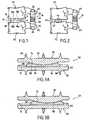
- FIG. 1a first embodiment of the spinal arthroplasty system according to the invention is shown in simplified form.
- the spinal arthroplasty systemconsists of an intervertebral disk prosthesis 12 and an intervertebral implant 14.
- the prosthesis intervertebral disc 12is mounted between the plates a and b vertebrae V1 and V2.
- the prosthesis 12consists essentially of two elements 16 and 18 which have a fixing face 18a, 16a on the trays of the vertebrae and a face 16b, 18b defining a common contact face in the form of a spherical cap. Thanks to the contact surfaces 18b and 16b, the two elements of the prosthesis can move in a relative manner thus allowing at least a part of the relative natural movement of the vertebrae V1 and V2.
- the intervertebral implant 14essentially consists of a shim 20 which has at its ends grooves 22 and 24 intended to receive the spinous processes A1 and A2.
- the securing of the wedge 14 with the spinners A1 and A2is achieved by two straps 26 and 28 whose ends are integral with the wedge 20 and which surround the processes.
- the central portion 30 of the shim 14is elastically deformable, which allows a certain relative movement between the vertebrae V1 and V2.
- the intervertebral implant 14acts as a limiting device for the relative movements of the two vertebrae. which would normally have played the posterior articulations when they are in good condition. It is also understood that the combination of the intervertebral disk prosthesis and the intervertebral implant makes it possible to solve the problem of replacing the natural intervertebral disk in the particular conditions under consideration.
- a spinal arthroplasty system forming part of the inventionis also shown in a simplified manner.
- the natural intervertebral disk 40has a more limited degeneration.
- the peripheral portion 42 of the natural diskis preserved and its nucleus pulposus is replaced with a nucleus prosthesis 44 which is substituted for the central part of the natural disk.
- the nucleus prosthesesare in themselves known as already indicated and generally consist of a hydrophilic material expanding to its final size within 24 or 48 hours after the operation. These nucleus prostheses which constitute in fact a partial prosthesis of the natural disc have viscoelastic characteristics tending to reproduce the mechanical behavior of the nucleus.
- nucleus prosthesisis only possible if the posterior structures of the vertebrae are in perfect condition since the nucleus prosthesis does not allow any guidance of the relative movements of the two vertebrae, whereas the disc prostheses intervertebral allow some limited guidance.
- Intervertebral disk nucleus prosthesesare described in European Spine Journal Volume 11, Supplement 2, October 2002 and in SPINE Volume 27 (11) June 1st, 2002 pp 1245 to 1247 .
- the nucleus prosthesis 44is completed by an intervertebral implant 14 identical to that described in connection with the figure 1 .
- the intervertebral implantis disposed between the spinous processes A1 and A2, and serves to limit the possibilities of relative movements between the two vertebrae to be substituted in this function for the posterior structures of the vertebrae which are degenerate .
- the spinal arthroplasty systemconsists of an intervertebral disc prosthesis which may have a large number of different structures and an intervertebral relative motion limitation implant which may also present many different structures.
- the first set 52 of the prosthesis 50comprises a fixation face 54 provided with anchoring means 56 in the vertebra plate and one face contact 58 in the form of a spherical cap.
- the second element 60 of the prosthesisis constituted by a fastener 62 whose attachment face 64 is provided with anchoring members such as 66 and a contact piece 68.
- the part 68comprises a sliding face 70 which can cooperate with the bottom of a counterbore 72 made in the first part 62.
- the second part 68also comprises an active face 74 in the form of a spherical cap to cooperate with the spherical cap-shaped surface 58 of the first assembly 52.
- intervertebral disk prosthesisnot only allows a relative rotulating movement through the presence of the two spherical caps but also a translational movement.
- Such an intervertebral disk prosthesisis described in more detail in the patent application. PCT WO 00/53127 .
- Other intervertebral implant prosthesesare described for example in the European patent application EP 176,728 .
- intervertebral disc implant prosthesisthat can be placed by posterior approach.
- Two preferred examples of prosthesis of this typewill be described with reference to Figures 4 and 5 on the one hand and 6 and 7 on the other hand.
- the prosthesis 80comprises a first set of prosthesis 82 and a second set of prosthesis 84.
- the first set 82consists of a first fixing element 86 and a first prosthesis element 88 while the second set 84 is constituted by a second fixing element 90 and a second prosthesis element 92.
- the fixing element 90will be described, the fixing element 86 being identical to it.
- the element 90has the general shape of a rectangular plate having a fixing face 93 provided with anchoring means 94 in the vertebra plate and an opposite face of cooperation 96.
- the groove 98has an engagement portion 98a that opens into one of the flanges of the part 90 and a second portion 98b perpendicular thereto.
- the Figure 5Cshows the prosthesis elements 88 and 92.
- the prosthesis element 88has a cooperation face 100 which comprises a recessed portion 102 in which is formed a locking member 104 constituted by a pin whose connecting portion 106 to the surface 102 has a reduced diameter. The dimensions of the pin 104 are determined in such a way that it can be engaged in the groove 98.
- the prosthesis member 88also has an active face 108 which essentially defines a convex spherical cap surface 110.
- the prosthesis element 92has the same architecture as the prosthesis element 88 with the exception that its active face 108 'defines a concave spherical cap-shaped surface 112 capable of cooperating with the convex spherical cap 110 of the prosthesis element 88.
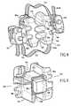
- the figure 6shows that the prosthesis 120 is constituted by two fastening elements 122 and 124 and by two prosthesis elements 126 and 128 each prosthesis element being constituted by two separate parts 126a and 126b for the element 126 and 128a and 128b for the element 128.
- the Figures 7A and 7Bshow the fixing element 124, the fixing element 122 being identical to it.
- the fixing element 124is constituted by a substantially rectangular plate 130 whose attachment face 130a is equipped with anchoring members such as 132.
- the other face 130b of the plate 130is equipped with two locking members 134 and 136.
- Each locking member 134, 136has the form of a bar whose cross section is T-shaped.
- each locking membercomprises a longitudinal groove 138 to give the locking members a certain elasticity.
- FIGS 7C to 7Eshow the parts 128a and 128b of the prosthesis element 128.
- Each piece 128a and 128b of the prosthesis element 128has in its cooperation face 140 a T-shaped groove 142 capable of receiving the locking members 134 and 136. It is understood that when the parts 128a and 128b are secured with the plate 130, these parts are immobilized relative to each other.
- the contact faces 144 of the parts 128a and 128bdefine a spherical cap portion.
- the two spherical cap portions thus definedbelong to the same spherical cap when the parts 128a and 128b are secured to one another by means of the part of the fastener element 124.
- the parts 126a and 126bhave an active face whose meeting defines a concave spherical cap.
- the embodiment of the intervertebral disk prosthesiswhich has just been described is particularly well suited to its introduction by posterior approach.
- the surgeoncan initially place on the vertebral plates simultaneously or successively the two fastening elements 122 and 124. Then, he sets up on either side of the spinal cord the parts 126a and 126b constituting the prosthesis element 126 by locking them on the fastening element 122 and, in the same manner, it sets up the parts 128a and 128b of the prosthesis element 128 and locks them on the fixing element 124.
- the positioning and locking of the parts constituting the prosthesis elementscan be achieved by displacements of these parts in a plane substantially perpendicular to the common axis of the vertebrae between which the prosthesis is to be placed.
- the implant 140is constituted as has already been explained by a interspinous wedge 142 and two straps or ligaments 144 and 146 to secure the ends of the wedge with the spinous processes of the vertebrae.
- the wedge 142comprises a body whose ends comprise grooves or housings 148 and 150 intended to receive the spinous processes.
- the central portion 152 of the body of the shimhas recesses 154, 156 parallel to the grooves 148 and 150.
- the recesses 154 and 156are intended to impart some elasticity or flexibility to the body of the hold and thus to allow some movement relative between the two vertebrae.
- the straps 144 and 146have a first end 146a, 144a which is integral with the body of the shim and a second end 144b, 146b which is engaged in self-locking locking devices 160 and 162 which can be clipped onto the side walls 164 and 166 of the hold body.
- This intervertebral implantis described in more detail in the patent application WO 02/071960 in the name of the plaintiff.
- the intervertebral implant shown on the figure 9is described in detail in the French patent application 01 015 494 in the name of the plaintiff.
- the shim 170 shown on the figure 9is constituted by two separate parts respectively referenced 172 and 174.
- the piece 172defines an upper groove 176 for a spinous process and the workpiece 174 defines a lower groove 178 for the spinous process of the other vertebra.
- the inner walls of parts 172 and 174define a substantially parallelepipedal volume V. Inside this volume V is mounted a substantially parallelepipedal part 180 made of an elastomeric material having compressibility properties.
- the two pieces 172 and 174are held together by a link 182 engaged in passages made in the parts 172 and 174 so that the link 182 completely surrounds the volume V.
- each piece 172 and 174 of the hold 170is equipped with clipping means 184 and 186 for fixing self-locking systems similar to the systems 160 and 162 of the figure 8 .
- These systemsmake it possible to fix with tightness analogous links to the links 144 and 146 of the figure 8 to ensure the securing of the wedge 170 with the spinous processes of the vertebrae.
- the wedge 170allows a movement of approximation of the spinners by compression of the piece 180.
- the link 182by limiting the relative movement possibilities of the pieces 172 and 174 limits the possibilities of spacing these same thorny.
- interepinal wedge having a certain elasticityis particularly interesting since the at least partial intervertebral disc prosthesis, whether it is a rotulative mechanical prosthesis or a disk nucleus prosthesis, allows a rotational movement. of the two vertebrae which is certainly limited by the hold, but which remains partly allowed.
- the recesses 154 and 156pass through the middle part of the wedge from one end to the other and in the embodiment of the figure 9 the middle part of the shim has a coefficient of elasticity greater than that of its ends.
Landscapes
- Health & Medical Sciences (AREA)
- Orthopedic Medicine & Surgery (AREA)
- Engineering & Computer Science (AREA)
- Biomedical Technology (AREA)
- Neurology (AREA)
- Life Sciences & Earth Sciences (AREA)
- Animal Behavior & Ethology (AREA)
- Veterinary Medicine (AREA)
- Public Health (AREA)
- Heart & Thoracic Surgery (AREA)
- General Health & Medical Sciences (AREA)
- Cardiology (AREA)
- Vascular Medicine (AREA)
- Transplantation (AREA)
- Oral & Maxillofacial Surgery (AREA)
- Surgery (AREA)
- Nuclear Medicine, Radiotherapy & Molecular Imaging (AREA)
- Medical Informatics (AREA)
- Molecular Biology (AREA)
- Prostheses (AREA)
Abstract
Description
Translated fromFrenchLa présente invention a pour objet un système d'arthroplastie rachidienne.The present invention relates to a spinal arthroplasty system.
Le principe du remplacement d'un disque intervertébral par une prothèse de type mécanique afin de réaliser une arthroplastie rachidienne est connu et décrit dans de nombreux documents.The principle of replacing an intervertebral disc with a mechanical type of prosthesis in order to perform spinal arthroplasty is known and described in numerous documents.
Cette opération visant à traiter les pathologies dégénératives du disque intervertébral peut être réalisée par un abord chirurgical antérieur ou par un abord postérieur.This operation to treat degenerative pathologies of the intervertebral disk can be performed by an earlier surgical approach or by a posterior approach.
Une autre technique pour permettre le traitement de ce type de pathologie consiste à utiliser des implants permettant le remplacement du seul nucléus pulposus du disque intervertébral. Ces implants sont dits prothèses de nucléus. La prothèse est insérée dans la partie centrale du disque intervertébral après ablation du nucléus. Ils sont en général constitués d'un matériau hydrophile s'expansant jusqu'à sa taille définitive dans les 24 ou 48 heures qui suivent l'opération et présentent des caractéristiques viscoélastiques tendant à reproduire le comportement mécanique du nucléus.Another technique for the treatment of this type of pathology consists in using implants allowing the replacement of the single nucleus pulposus of the intervertebral disc. These implants are called nucleus prostheses. The prosthesis is inserted into the central part of the intervertebral disc after removal of the nucleus. They are generally made of a hydrophilic material expanding to its final size within 24 or 48 hours after the operation and have viscoelastic characteristics tending to reproduce the mechanical behavior of the nucleus.
Toutefois, les indications relatives à l'utilisation des prothèses de disque intervertébral, quelque soit la voie d'abord utilisée ou l'utilisation de prothèse de nucléus, sont limitées par l'état des structures postérieures du niveau vertébral à traiter. On entend par structure postérieure, les articulations postérieures réalisées entre les facettes articulaires des vertèbres disposées au-dessus et en dessous du disque malade. Dans les cas où les articulations postérieures sont elles-mêmes atteintes par la dégénérescence, l'indication de prothèse de disque intervertébral ou de prothèse de nucléus est alors souvent jugée trop sévère pour qu'une prothèse discale partielle ou totale puisse être utilisée dans de bonnes conditions et avec des chances réelles de succès. Cela est dû notamment au fait qu'aussi bien dans le cas de prothèse intervertébrale mécanique que de prothèse de nucléus, ces dispositifs visant à remplacer au moins partiellement le disque intervertébral naturel ne comportent pas de butée mécanique des mouvements relatifs des vertèbres adjacentes. Dans ce cas, les vertèbres elles-mêmes et du fait de leur dégénérescence ne constituent plus ces butées mécaniques de limitation de mouvement relatif. Le chirurgien n'a donc souvent pas d'autres alternatives que de procéder à une fusion du niveau vertébral concerné en utilisant par exemple un système comportant des vis pédiculaires reliées à des tiges pour immobiliser les deux vertèbres, ce qui bien sûr peut diminuer le confort du patient.However, the indications relating to the use of intervertebral disc prostheses, whatever the approach used or the use of nucleus prosthesis, are limited by the state of the posterior structures of the vertebral level to be treated. By posterior structure is meant the posterior joints formed between the articular facets of the vertebrae disposed above and below the diseased disc. In cases where the posterior joints are themselves affected by degeneration, the indication of intervertebral disk prosthesis or nucleus prosthesis is then often considered too severe for a partial or total disc prosthesis to be used in good conditions and with real chances of success. This is due in particular to the fact that both in the case of mechanical intervertebral prosthesis and nucleus prosthesis, these devices for replacing at least partially the natural intervertebral disc do not comprise mechanical stop relative movements of adjacent vertebrae. In this case, the vertebrae themselves and because of their degeneracy no longer constitute these mechanical stops relative movement limitation. The surgeon therefore often has no other alternative than perform a fusion of the vertebral level concerned using for example a system comprising pedicle screws connected to rods to immobilize the two vertebrae, which of course can reduce the comfort of the patient.
Un autre exemple de système d'arthroplastie rachidienne est divulgué dans la demande
Un objet de la présente invention est de fournir un système d'arthroplastie rachidienne qui permet l'utilisation de prothèses de disque intervertébral totales même dans le cas de dégénérescence sévère des éléments articulaires postérieurs des vertèbres disposées au-dessus et en dessous du disque malade.An object of the present invention is to provide a spinal arthroplasty system which allows the use of total intervertebral disc prostheses even in the case of severe degeneration of the posterior articular elements of the vertebrae disposed above and below the diseased disc.
Pour atteindre ce but selon l'invention, le système d'arthroplastie rachidienne destiné à être mis en place entre deux vertèbres contiguës se caractérise en ce qu'il comprend une prothèse totale de disque intervertébral choisie dans le groupe des prothèses mécaniques rotulantes et une cale destinée à être disposée entre les apophyses épineuses des deux vertèbres, ladite cale comportant à chacune de ses extrémités un logement pour recevoir une des apophyses épineuses, et au moins un lien pour maintenir chaque apophyse dans un logement de ladite cale.To achieve this object according to the invention, the spinal arthroplasty system intended to be placed between two contiguous vertebrae is characterized in that it comprises a total intervertebral disk prosthesis chosen from the group of mechanical rotulative prostheses and a shim intended to be disposed between the spinous processes of the two vertebrae, said wedge having at each of its ends a housing for receiving one of the spinous processes, and at least one link for holding each apophysis in a housing of said wedge.
On comprend que grâce à l'utilisation de l'implant intervertébral disposé entre les apophyses épineuses des vertèbres disposées de part et d'autre du disque malade, on met en oeuvre la fonction de butée mécanique de mouvement relatif que les vertèbres objet de la dégénérescence ne pouvaient plus mettre en oeuvre. Ainsi, il est possible d'utiliser un implant mécanique rotulant de disque intervertébral ou un implant de nucléus dans des conditions optimales. En effet, la cale de l'implant intervertébral permet de limiter les mouvements relatifs des deux vertèbres dans les différents plans de mobilité.It will be understood that by virtue of the use of the intervertebral implant disposed between the spinous processes of the vertebrae disposed on either side of the diseased disc, the relative mechanical stop function of relative movement is applied which the vertebrae are subject to degeneration. could no longer implement. Thus, it is possible to use a mechanical intervertebral disc spindle implant or a nucleus implant under optimal conditions. In fact, the wedge of the intervertebral implant makes it possible to limit the relative movements of the two vertebrae in the different mobility plans.
Selon un premier mode de mise en oeuvre, le système comprend une prothèse de disque intervertébral comportant un premier ensemble présentant une face de fixation sur une vertèbre et une face active dont une partie a la forme d'une première calotte sensiblement sphérique concave, et un deuxième ensemble présentant une face de fixation sur l'autre vertèbre et une face active dont une partie a la forme d'une deuxième calotte sensiblement sphérique convexe pour coopérer avec la première calotte sphérique. Comme cela est par ailleurs bien connu, la prothèse de disque constituée par les deux éléments comportant les calottes sphériques conjuguées permet d'autoriser des mouvements relatifs des deux vertèbres proches des deux mouvements relatifs naturels.According to a first embodiment, the system comprises an intervertebral disk prosthesis comprising a first assembly having a fixation face on a vertebra and an active face, a portion of which has the shape of a first substantially spherical concave cap, and a second assembly having a fixing face on the other vertebra and an active face, a portion of which has the shape of a second substantially convex spherical cap to cooperate with the first spherical cap. As is otherwise well Known, the disk prosthesis constituted by the two elements comprising the spherical conjugate caps allows to allow relative movements of the two vertebrae close to the two natural relative movements.
D'autres caractéristiques et avantages de l'invention apparaîtront mieux à la lecture de la description qui suit de plusieurs modes de réalisation de l'invention donnés à titre d'exemples non limitatifs. La description se réfère aux dessins annexés sur lesquels :
- la
figure 1 est une vue simplifiée du premier mode de mise en oeuvre avec une prothèse de disque, intervertébral ; - la
figure 2 est une vue simplifiée d'un système utilisant une prothèse de nucléus, me faisant pas partie de l'invention définie dans la revendication 1 annexée ; - les
figures 3A et 3B illustrent en coupe diamétrale un premier mode de réalisation de la prothèse de disque intervertébral ; - la
figure 4 montre en perspective un deuxième mode de réalisation de la prothèse de disque intervertébral ; - les
figures 5A, 5B et 5C montrent les différentes parties de la prothèse de disque intervertébral représentée sur lafigure 4 ; - la
figure 6 montre en perspective un troisième mode de réalisation de la prothèse de disque intervertébral ; - les
figures 7A à 7E montrent en détail les différentes parties de la prothèse de disque intervertébral montrée sur lesfigures 6 ; - la
figure 8 montre en perspective un premier mode de réalisation de l'implant intervertébral ; et - la
figure 9 montre en perspective un deuxième mode de réalisation de l'implant intervertébral.
- the
figure 1 is a simplified view of the first embodiment with a disk prosthesis, intervertebral; - the
figure 2 is a simplified view of a system using a nucleus prosthesis, not forming part of the invention defined in appended claim 1; - the
Figures 3A and 3B illustrate in diametrical section a first embodiment of the intervertebral disk prosthesis; - the
figure 4 shows in perspective a second embodiment of the intervertebral disk prosthesis; - the
FIGS. 5A, 5B and 5C show the different parts of the intervertebral disc prosthesis shown on thefigure 4 ; - the
figure 6 shows in perspective a third embodiment of the intervertebral disk prosthesis; - the
Figures 7A to 7E show in detail the different parts of the intervertebral disk prosthesis shown on thefigures 6 ; - the
figure 8 shows in perspective a first embodiment of the intervertebral implant; and - the
figure 9 shows in perspective a second embodiment of the intervertebral implant.
Sur la
Sur cette figure, apparaissent les vertèbres V1 et V2 ainsi que leurs apophyses épineuses A1 et A2. Dans ce mode de réalisation, le système d'arthroplastie rachidienne est constitué par une prothèse de disque intervertébral 12 et par un implant intervertébral 14. La prothèse de disque intervertébral 12 est montée entre les plateaux a et b des vertèbres V1 et V2. La prothèse 12 est essentiellement constituée par deux éléments 16 et 18 qui présentent une face 18a, 16a de fixation sur les plateaux des vertèbres et une face 16b, 18b définissant une face commune de contact en forme de calotte sphérique. Grâce aux surfaces de contact 18b et 16b, les deux éléments de la prothèse peuvent se déplacer de façon relative autorisant ainsi au moins une partie du mouvement naturel relatif des vertèbres V1 et V2.In this figure, appear the vertebrae V1 and V2 and their spinous processes A1 and A2. In this embodiment, the spinal arthroplasty system consists of an
L'implant intervertébral 14 est essentiellement constitué par une cale 20 qui présente à ses extrémités des gorges 22 et 24 destinées à recevoir les apophyses épineuses A1 et A2. La solidarisation de la cale 14 avec les épineuses A1 et A2 est réalisée par deux sangles 26 et 28 dont les extrémités sont solidaires de la cale 20 et qui entourent les apophyses. De préférence, la partie centrale 30 de la cale 14 est élastiquement déformable, ce qui autorise un certain mouvement relatif entre les vertèbres V1 et V2.The
On comprend que dans le cas considéré pour l'invention, c'est-à-dire dans le cas où les articulations postérieures des vertèbres sont atteintes par une dégénérescence, l'implant intervertébral 14 joue le rôle de limitateur des mouvements relatifs des deux vertèbres qu'auraient joué normalement les articulations postérieures lorsqu'elles sont en bon état. On comprend également que la combinaison de la prothèse de disque intervertébral et de l'implant intervertébral permet de résoudre le problème du remplacement du disque intervertébral naturel dans les conditions particulières considérées.It is understood that in the case considered for the invention, that is to say in the case where the posterior articulations of the vertebrae are affected by degeneration, the
Sur la
Des prothèses de nucleus de disques intervertébraux sont décrites dans
Dans ce système d'arthroplastie rachidienne, la prothèse de nucléus 44 est complétée par un implant intervertébral 14 identique à celui qui a été décrit en liaison avec la
On comprend que selon le premier mode de réalisation de l'invention, le système d'arthroplastie rachidienne est constitué par une prothèse de disque intervertébral qui peut présenter un grand nombre de structures différentes et par un implant intervertébral de limitation de mouvement relatif qui peut également présenter de nombreuses structures différentes.It will be understood that according to the first embodiment of the invention, the spinal arthroplasty system consists of an intervertebral disc prosthesis which may have a large number of different structures and an intervertebral relative motion limitation implant which may also present many different structures.
Dans la description qui suit, on va décrire différentes prothèses de disque intervertébral utilisables dans l'invention, ainsi que différents implants intervertébraux également utilisables dans cette invention.In the description which follows, various intervertebral disk prostheses used in the invention will be described, as well as various intervertebral implants also usable in this invention.
Sur les
On comprend que cette prothèse de disque intervertébral permet non seulement un mouvement relatif rotulant grâce à la présence des deux calottes sphériques mais également un mouvement de translation. Une telle prothèse de disque intervertébral est décrite plus en détails dans la demande de brevet
Dans tous les cas, la mise en place de la prothèse d'implant intervertébral du type décrit précédemment se fait par abord antérieur. On comprend que le plus souvent une telle solution n'est pas optimale puisqu'en revanche l'implant intervertébral 14 doit être mis en place par abord postérieur.In all cases, the insertion of the intervertebral implant prosthesis of the type described above is done by anterior approach. It is understood that most often such a solution is not optimal since, on the other hand, the
Pour remédier à cet inconvénient, il est souhaitable d'utiliser une prothèse d'implant de disque intervertébral susceptible d'être mise en place par abord postérieur. On va décrire deux exemples préférés de prothèse de ce type par référence aux
En se référant tout d'abord aux
En se référant aux
Dans la face de coopération 96 est ménagée une rainure 98 débouchant dans la face 96 et dont la section droite est en forme de T comme le montre la
La
L'élément de prothèse 92 présente la même architecture que l'élément de prothèse 88 à l'exception du fait que sa face active 108' définit une surface en forme de calotte sphérique concave 112 apte à coopérer avec la calotte sphérique convexe 110 de l'élément de prothèse 88.The
La mise en place par abord postérieur de la prothèse de disque intervertébral 80 est réalisée de la manière suivante :
- dans une première phase le chirurgien met en place successivement ou simultanément les éléments de
fixation 82et 84. Cette mise en place par abord postérieur est possible du fait de la dimension relativement réduite des éléments de fixation. Dans un deuxième temps, le chirurgien introduit successivement chaque élément de prothèse 88et 92 de telle manière que le téton d'ancrage 104 pénètre dans la partie d'introduction de la rainure 98 de l'élément de fixation correspondant. Puis par un pivotement de 90° le chirurgien déplace le téton 104 dans la deuxième partie 98b de la rainure 98 jusqu'à obtention de son immobilisation. On obtient ainsi un verrouillage de chaque élément de prothèse sur l'élément de fixation. Il faut souligner que grâce aux modes de réalisation des éléments de verrouillage respectifs (rainure 98, téton 104) le verrouillage des éléments de prothèse sur les éléments de fixation se fait uniquement par un mouvement des éléments de prothèse dans un plan perpendiculaire à l'axe commun des deux vertèbres entre lesquelles la prothèse doit être mise en place.
- in a first phase the surgeon sets up successively or simultaneously the
fastening elements prosthesis element anchor pin 104 enters the insertion portion of thegroove 98 of the corresponding fastening element. Then by pivoting 90 ° the surgeon moves thepin 104 in thesecond portion 98b of thegroove 98 until it is immobilized. This provides a lock of each prosthetic element on the fastener. It should be emphasized that, thanks to the embodiments of the respective locking elements (groove 98, pin 104), the locking of the prosthesis elements on the fastening elements is done solely by a movement of the prosthesis elements in a plane perpendicular to the axis. the two vertebrae between which the prosthesis is to be placed.
En se référant maintenant aux
La
Les
Les
Chaque pièce 128a et 128b de l'élément de prothèse 128 comporte dans sa face de coopération 140 une rainure débouchante 142 en forme de T apte à recevoir les organes de verrouillage 134 et 136. On comprend que lorsque les pièces 128a et 128b sont solidarisées avec la plaque 130, ces pièces sont immobilisées l'une par rapport à l'autre. Les faces de contact 144 des pièces 128a et 128b définissent une portion de calotte sphérique. Les deux portions de calottes sphériques ainsi définies appartiennent à une même calotte sphérique lorsque les pièces 128a et 128b sont solidarisées l'une à l'autre à l'aide de la pièce de l'élément de fixation 124. De la même manière, les pièces 126a et 126b ont une face active dont la réunion définit une calotte sphérique concave.Each
On comprend que le mode de réalisation de la prothèse de disque intervertébral qui vient d'être décrit est particulièrement bien adapté à sa mise en place par abord postérieur. En effet, le chirurgien peut dans un premier temps mettre en place sur les plateaux vertébraux simultanément ou successivement les deux éléments de fixation 122 et 124. Ensuite, il met en place de part et d'autre de la moelle épinière les pièces 126a et 126b constituant l'élément de prothèse 126 en verrouillant celles-ci sur l'élément de fixation 122 puis, de la même manière, il met en place les pièces 128a et 128b de l'élément de prothèse 128 et verrouille celles-ci sur l'élément de fixation 124. De plus, comme dans le mode de réalisation décrit précédemment, la mise en place et le verrouillage des pièces constituant les éléments de prothèse peut être réalisée par des déplacements de ces pièces dans un plan sensiblement perpendiculaire à l'axe commun des vertèbres entre lesquelles la prothèse doit être placée.It is understood that the embodiment of the intervertebral disk prosthesis which has just been described is particularly well suited to its introduction by posterior approach. In fact, the surgeon can initially place on the vertebral plates simultaneously or successively the two
En se référant maintenant aux
Sur la
L'implant intervertébral représenté sur la
La cale 170 représentée sur la
On comprend que grâce à la présence du bloc élastiquement déformable 180, la cale 170 autorise un mouvement de rapprochement des épineuses par compression de la pièce 180. En revanche, le lien 182 en limitant les possibilités de déplacements relatifs des pièces 172 et 174 limite les possibilités d'écartement de ces mêmes épineuses.It will be understood that, thanks to the presence of the elastically
L'utilisation d'une cale interépinale présentant une certaine élasticité est particulièrement intéressante puisque la prothèse au moins partielle de disque intervertébral, qu'il s'agisse d'une prothèse mécanique rotulante ou d'une prothèse de nucleus de disque autorise un mouvement rotulant des deux vertèbres qui est certes limité par la cale, mais qui reste en partie autorisé.The use of an interepinal wedge having a certain elasticity is particularly interesting since the at least partial intervertebral disc prosthesis, whether it is a rotulative mechanical prosthesis or a disk nucleus prosthesis, allows a rotational movement. of the two vertebrae which is certainly limited by the hold, but which remains partly allowed.
Il va de soi que d'autres types d'implants intervertébraux disposés entre les apophyses épineuses des vertèbres entourant le disque intervertébral à remplacer pourraient être utilisés dès lors que, de préférence, il présentent certaines possibilités illimitées de déplacements relatifs des apophyses épineuses des vertèbres.It goes without saying that other types of intervertebral implants disposed between the spinous processes of the vertebrae surrounding the intervertebral disk to be replaced could be used provided that, preferably, there are certain unlimited possibilities of relative movements of the spinous processes of the vertebrae.
Plus généralement, de préférence, dans le mode de réalisation de la
Claims (7)
- A spinal arthroplasty system intended to be placed between two contiguous vertebrae, the system comprising an intervertebral implant (14) comprising:- a spacer (20) intended to be placed between the spinous processes of the two vertebrae, said spacer (20) having a housing (22, 24) at each of its ends for receiving one of the spinous processes; and- at least one tie (26, 28) for holding each process in a housing (22, 24) of said spacer (20),
the system beingcharacterized in that it further comprises a total prosthesis of the intervertebral disk (12) selected from the group of ball-and-socket type mechanical prostheses. - A spinal arthroplasty system according to claim 1,characterized in that it comprises a ball-and-socket type mechanical prosthesis of the intervertebral disk (12) comprising:- a first assembly (52, 82) presenting a fastening face for fastening to a vertebra and an active face having a portion in the form of a first cap being substantially spherical convex; and- a second assembly (60, 84) presenting a fastening face for fastening to a vertebra and an active face including a portion in the form of a second cap being substantially spherical convex, for co-operating with the first spherical cap.
- A spinal arthroplasty system according to claim 2,characterized in that each of said first and second assemblies of said prosthesis includes a fastener element (86, 90, 122, 124) including said fastening face and a prosthesis element (88, 92, 126, 128) including said active face, said elements being provided with mechanical means for securing them together.
- A spinal arthroplasty system according to claim 2 or 3,characterized in that each prosthesis element (126, 128) comprises two distinct parts (126a, 126b, 128a, 128b) intended to be placed side by side, each part having a fastening face and an active face, andin that each prosthesis assembly further comprises means (122, 124) for securing the two parts together, the active faces of the two secured parts defining one of said spherical caps.
- A spinal arthroplasty system according to claim 1,characterized in that each prosthesis assembly is constituted by a single part.
- A spinal arthroplasty system according to any one of claims 1 to 5,characterized in that said spacer (170) comprises two ends (172, 174), each including one of said housings (176, 178), and a middle portion including means (180) deformable in compression that are active when the two vertebrae move towards each other, and tie means (182) for limiting the extent to which the ends of said spacer can move apart under the effect of mutual separation movements between the vertebrae.
- A spinal arthroplasty system according to any one of claims 1 to 5,characterized in that said spacer (140) is made out of a single material and its middle portion (152) includes recesses (154, 156) passing right through it.
Applications Claiming Priority (2)
| Application Number | Priority Date | Filing Date | Title |
|---|---|---|---|
| FR0405720AFR2870719B1 (en) | 2004-05-27 | 2004-05-27 | SPINAL ARTHROPLASTY SYSTEM |
| PCT/FR2005/001301WO2005117728A1 (en) | 2004-05-27 | 2005-05-26 | Spinal arthoplasty system |
Publications (2)
| Publication Number | Publication Date |
|---|---|
| EP1753353A1 EP1753353A1 (en) | 2007-02-21 |
| EP1753353B1true EP1753353B1 (en) | 2011-11-09 |
Family
ID=34948692
Family Applications (1)
| Application Number | Title | Priority Date | Filing Date |
|---|---|---|---|
| EP05773210ACeasedEP1753353B1 (en) | 2004-05-27 | 2005-05-26 | Spinal arthoplasty system |
Country Status (6)
| Country | Link |
|---|---|
| US (1) | US20080015693A1 (en) |
| EP (1) | EP1753353B1 (en) |
| JP (1) | JP2008500085A (en) |
| AU (1) | AU2005249247A1 (en) |
| FR (1) | FR2870719B1 (en) |
| WO (1) | WO2005117728A1 (en) |
Families Citing this family (67)
| Publication number | Priority date | Publication date | Assignee | Title |
|---|---|---|---|---|
| US6068630A (en)* | 1997-01-02 | 2000-05-30 | St. Francis Medical Technologies, Inc. | Spine distraction implant |
| US7972337B2 (en) | 2005-12-28 | 2011-07-05 | Intrinsic Therapeutics, Inc. | Devices and methods for bone anchoring |
| US7717961B2 (en) | 1999-08-18 | 2010-05-18 | Intrinsic Therapeutics, Inc. | Apparatus delivery in an intervertebral disc |
| US7998213B2 (en)* | 1999-08-18 | 2011-08-16 | Intrinsic Therapeutics, Inc. | Intervertebral disc herniation repair |
| EP1624832A4 (en)* | 1999-08-18 | 2008-12-24 | Intrinsic Therapeutics Inc | Devices and method for augmenting a vertebral disc nucleus |
| US8323341B2 (en) | 2007-09-07 | 2012-12-04 | Intrinsic Therapeutics, Inc. | Impaction grafting for vertebral fusion |
| US7553329B2 (en)* | 1999-08-18 | 2009-06-30 | Intrinsic Therapeutics, Inc. | Stabilized intervertebral disc barrier |
| CA2425951C (en)* | 1999-08-18 | 2008-09-16 | Intrinsic Therapeutics, Inc. | Devices and method for nucleus pulposus augmentation and retention |
| US7094258B2 (en)* | 1999-08-18 | 2006-08-22 | Intrinsic Therapeutics, Inc. | Methods of reinforcing an annulus fibrosis |
| FR2812186B1 (en)* | 2000-07-25 | 2003-02-28 | Spine Next Sa | FLEXIBLE CONNECTION PIECE FOR SPINAL STABILIZATION |
| FR2812185B1 (en) | 2000-07-25 | 2003-02-28 | Spine Next Sa | SEMI-RIGID CONNECTION PIECE FOR RACHIS STABILIZATION |
| FR2824261B1 (en) | 2001-05-04 | 2004-05-28 | Ldr Medical | INTERVERTEBRAL DISC PROSTHESIS AND IMPLEMENTATION METHOD AND TOOLS |
| US8048117B2 (en) | 2003-05-22 | 2011-11-01 | Kyphon Sarl | Interspinous process implant and method of implantation |
| US7909853B2 (en)* | 2004-09-23 | 2011-03-22 | Kyphon Sarl | Interspinous process implant including a binder and method of implantation |
| FR2846550B1 (en) | 2002-11-05 | 2006-01-13 | Ldr Medical | INTERVERTEBRAL DISC PROSTHESIS |
| JP2007515988A (en)* | 2003-06-20 | 2007-06-21 | イントリンジック セラピューティックス インコーポレイテッド | Device and method for delivering an implant from an annular defect of an intervertebral disc |
| US7875077B2 (en)* | 2004-01-09 | 2011-01-25 | Warsaw Orthopedic, Inc. | Support structure device and method |
| US20050171608A1 (en) | 2004-01-09 | 2005-08-04 | Sdgi Holdings, Inc. | Centrally articulating spinal device and method |
| US7901459B2 (en)* | 2004-01-09 | 2011-03-08 | Warsaw Orthopedic, Inc. | Split spinal device and method |
| EP2113227B1 (en) | 2004-02-04 | 2015-07-29 | LDR Medical | Intervertebral disc prosthesis |
| FR2865629B1 (en) | 2004-02-04 | 2007-01-26 | Ldr Medical | INTERVERTEBRAL DISC PROSTHESIS |
| FR2869528B1 (en) | 2004-04-28 | 2007-02-02 | Ldr Medical | INTERVERTEBRAL DISC PROSTHESIS |
| US8012209B2 (en)* | 2004-09-23 | 2011-09-06 | Kyphon Sarl | Interspinous process implant including a binder, binder aligner and method of implantation |
| US9055981B2 (en) | 2004-10-25 | 2015-06-16 | Lanx, Inc. | Spinal implants and methods |
| US8241330B2 (en) | 2007-01-11 | 2012-08-14 | Lanx, Inc. | Spinous process implants and associated methods |
| WO2006058221A2 (en) | 2004-11-24 | 2006-06-01 | Abdou Samy M | Devices and methods for inter-vertebral orthopedic device placement |
| FR2879436B1 (en) | 2004-12-22 | 2007-03-09 | Ldr Medical | INTERVERTEBRAL DISC PROSTHESIS |
| US7488330B2 (en)* | 2005-01-27 | 2009-02-10 | Depuy Spine, Inc. | Modular static intervertebral trial |
| US8034079B2 (en) | 2005-04-12 | 2011-10-11 | Warsaw Orthopedic, Inc. | Implants and methods for posterior dynamic stabilization of a spinal motion segment |
| FR2887762B1 (en) | 2005-06-29 | 2007-10-12 | Ldr Medical Soc Par Actions Si | INTERVERTEBRAL DISC PROSTHESIS INSERTION INSTRUMENTATION BETWEEN VERTEBRATES |
| FR2891135B1 (en) | 2005-09-23 | 2008-09-12 | Ldr Medical Sarl | INTERVERTEBRAL DISC PROSTHESIS |
| FR2893838B1 (en) | 2005-11-30 | 2008-08-08 | Ldr Medical Soc Par Actions Si | PROSTHESIS OF INTERVERTEBRAL DISC AND INSTRUMENTATION OF INSERTION OF THE PROSTHESIS BETWEEN VERTEBRATES |
| US8105357B2 (en)* | 2006-04-28 | 2012-01-31 | Warsaw Orthopedic, Inc. | Interspinous process brace |
| FR2907329B1 (en)* | 2006-10-20 | 2009-02-27 | Jean Taylor | INTEREPINEAL VERTEBRAL PROSTHESIS |
| US9247968B2 (en) | 2007-01-11 | 2016-02-02 | Lanx, Inc. | Spinous process implants and associated methods |
| US9265532B2 (en) | 2007-01-11 | 2016-02-23 | Lanx, Inc. | Interspinous implants and methods |
| US8465546B2 (en) | 2007-02-16 | 2013-06-18 | Ldr Medical | Intervertebral disc prosthesis insertion assemblies |
| JP5087081B2 (en)* | 2007-05-11 | 2012-11-28 | トヨタ自動車株式会社 | Side impact airbag control device |
| FR2916956B1 (en) | 2007-06-08 | 2012-12-14 | Ldr Medical | INTERSOMATIC CAGE, INTERVERTEBRAL PROSTHESIS, ANCHORING DEVICE AND IMPLANTATION INSTRUMENTATION |
| US20080312694A1 (en)* | 2007-06-15 | 2008-12-18 | Peterman Marc M | Dynamic stabilization rod for spinal implants and methods for manufacturing the same |
| US20110196492A1 (en)* | 2007-09-07 | 2011-08-11 | Intrinsic Therapeutics, Inc. | Bone anchoring systems |
| US20090093819A1 (en)* | 2007-10-05 | 2009-04-09 | Abhijeet Joshi | Anisotropic spinal stabilization rod |
| US20090093843A1 (en)* | 2007-10-05 | 2009-04-09 | Lemoine Jeremy J | Dynamic spine stabilization system |
| US20090248077A1 (en)* | 2008-03-31 | 2009-10-01 | Derrick William Johns | Hybrid dynamic stabilization |
| JP5687197B2 (en) | 2008-09-03 | 2015-03-18 | シンピライカ スパイン, インコーポレイテッド | Method and apparatus for coupling a prosthesis to a spinal segment |
| US20100114165A1 (en)* | 2008-11-04 | 2010-05-06 | Abbott Spine, Inc. | Posterior dynamic stabilization system with pivoting collars |
| US20100160968A1 (en)* | 2008-12-19 | 2010-06-24 | Abbott Spine Inc. | Systems and methods for pedicle screw-based spine stabilization using flexible bands |
| US8114135B2 (en)* | 2009-01-16 | 2012-02-14 | Kyphon Sarl | Adjustable surgical cables and methods for treating spinal stenosis |
| US8764806B2 (en) | 2009-12-07 | 2014-07-01 | Samy Abdou | Devices and methods for minimally invasive spinal stabilization and instrumentation |
| FR2961687B1 (en)* | 2010-06-23 | 2015-05-22 | Cousin Biotech | LONGILINE ELEMENT RETENTION DEVICE SUITABLE FOR MAINTAINING DETERMINED INTERVERTEBRAL CLEARANCE |
| US8496689B2 (en) | 2011-02-23 | 2013-07-30 | Farzad Massoudi | Spinal implant device with fusion cage and fixation plates and method of implanting |
| US8425560B2 (en) | 2011-03-09 | 2013-04-23 | Farzad Massoudi | Spinal implant device with fixation plates and lag screws and method of implanting |
| US8449616B2 (en)* | 2011-03-15 | 2013-05-28 | Axiomed Spine Corporation | Apparatus for replacing a damaged spinal disc |
| US8845728B1 (en) | 2011-09-23 | 2014-09-30 | Samy Abdou | Spinal fixation devices and methods of use |
| US11812923B2 (en) | 2011-10-07 | 2023-11-14 | Alan Villavicencio | Spinal fixation device |
| US20130226240A1 (en) | 2012-02-22 | 2013-08-29 | Samy Abdou | Spinous process fixation devices and methods of use |
| US9198767B2 (en) | 2012-08-28 | 2015-12-01 | Samy Abdou | Devices and methods for spinal stabilization and instrumentation |
| US9320617B2 (en) | 2012-10-22 | 2016-04-26 | Cogent Spine, LLC | Devices and methods for spinal stabilization and instrumentation |
| US10857003B1 (en) | 2015-10-14 | 2020-12-08 | Samy Abdou | Devices and methods for vertebral stabilization |
| US10973648B1 (en) | 2016-10-25 | 2021-04-13 | Samy Abdou | Devices and methods for vertebral bone realignment |
| US10744000B1 (en) | 2016-10-25 | 2020-08-18 | Samy Abdou | Devices and methods for vertebral bone realignment |
| US10881523B2 (en)* | 2017-07-05 | 2021-01-05 | Keith L Doty | Motion preserving spinal total disc replacement apparatus, method and related systems |
| US11179248B2 (en) | 2018-10-02 | 2021-11-23 | Samy Abdou | Devices and methods for spinal implantation |
| CA3147517A1 (en) | 2019-08-21 | 2021-02-25 | Cheng-Lun SOO | Interspinous-interlaminar stabilization systems and methods |
| WO2021127635A1 (en) | 2019-12-19 | 2021-06-24 | FloSpine, LLC | Expandable intervertebral implant |
| US11752007B2 (en) | 2021-01-05 | 2023-09-12 | FloSpine, LLC | Expandable intervertebral implant system and method |
| CN117442394B (en)* | 2023-12-25 | 2024-03-08 | 北京爱康宜诚医疗器材有限公司 | Linkage type vertebral body prosthesis |
Family Cites Families (12)
| Publication number | Priority date | Publication date | Assignee | Title |
|---|---|---|---|---|
| EP0176728B1 (en) | 1984-09-04 | 1989-07-26 | Humboldt-Universität zu Berlin | Intervertebral-disc prosthesis |
| US5425773A (en)* | 1992-01-06 | 1995-06-20 | Danek Medical, Inc. | Intervertebral disk arthroplasty device |
| US5676701A (en)* | 1993-01-14 | 1997-10-14 | Smith & Nephew, Inc. | Low wear artificial spinal disc |
| US6679915B1 (en)* | 1998-04-23 | 2004-01-20 | Sdgi Holdings, Inc. | Articulating spinal implant |
| US6368350B1 (en) | 1999-03-11 | 2002-04-09 | Sulzer Spine-Tech Inc. | Intervertebral disc prosthesis and method |
| FR2822051B1 (en)* | 2001-03-13 | 2004-02-27 | Spine Next Sa | INTERVERTEBRAL IMPLANT WITH SELF-LOCKING ATTACHMENT |
| FR2828398B1 (en)* | 2001-08-08 | 2003-09-19 | Jean Taylor | VERTEBRA STABILIZATION ASSEMBLY |
| FR2832917B1 (en)* | 2001-11-30 | 2004-09-24 | Spine Next Sa | ELASTICALLY DEFORMABLE INTERVERTEBRAL IMPLANT |
| US6572653B1 (en)* | 2001-12-07 | 2003-06-03 | Rush E. Simonson | Vertebral implant adapted for posterior insertion |
| US6899735B2 (en)* | 2002-10-02 | 2005-05-31 | Sdgi Holdings, Inc. | Modular intervertebral prosthesis system |
| US7083649B2 (en)* | 2002-10-29 | 2006-08-01 | St. Francis Medical Technologies, Inc. | Artificial vertebral disk replacement implant with translating pivot point |
| US7235101B2 (en)* | 2003-09-15 | 2007-06-26 | Warsaw Orthopedic, Inc. | Revisable prosthetic device |
- 2004
- 2004-05-27FRFR0405720Apatent/FR2870719B1/ennot_activeExpired - Fee Related
- 2005
- 2005-05-26WOPCT/FR2005/001301patent/WO2005117728A1/enactiveApplication Filing
- 2005-05-26USUS11/597,758patent/US20080015693A1/ennot_activeAbandoned
- 2005-05-26EPEP05773210Apatent/EP1753353B1/ennot_activeCeased
- 2005-05-26JPJP2007514015Apatent/JP2008500085A/enactivePending
- 2005-05-26AUAU2005249247Apatent/AU2005249247A1/ennot_activeAbandoned
Also Published As
| Publication number | Publication date |
|---|---|
| FR2870719A1 (en) | 2005-12-02 |
| WO2005117728A1 (en) | 2005-12-15 |
| US20080015693A1 (en) | 2008-01-17 |
| JP2008500085A (en) | 2008-01-10 |
| FR2870719B1 (en) | 2007-09-21 |
| AU2005249247A1 (en) | 2005-12-15 |
| EP1753353A1 (en) | 2007-02-21 |
Similar Documents
| Publication | Publication Date | Title |
|---|---|---|
| EP1753353B1 (en) | Spinal arthoplasty system | |
| EP1675535B1 (en) | Intervertebral implant | |
| EP1414358B1 (en) | Vertebra stabilizing assembly | |
| EP0441668B1 (en) | Sacrum bearing block for rachidian osteosynthesis | |
| EP1585448B1 (en) | System for treatment of degeneration of an intervertebral disc | |
| EP1948092B1 (en) | Implant, especially partial implant of the head of the ulna | |
| WO2005118015A1 (en) | Set for treating the degeneracy of an intervertebral disc | |
| FR2858546A1 (en) | INTERVERTEBRAL DISC PROSTHESIS | |
| WO1994004100A1 (en) | Intervertebral disk prosthesis | |
| FR2909860A1 (en) | Partial or total intervertebral disk articular prosthesis for use in orthopedic surgery, has upper and lower articular surfaces respectively tapered at pole by other surfaces delimiting mobility space between them | |
| EP1720472A1 (en) | Dynamic linking element for a spinal attachment system, and spinal attachment system including said linking element | |
| FR2971139A1 (en) | PLATE FOR THE OSTEOSYNTHESIS OF THE LOMBO-SACRED JOINT | |
| WO2005053579A1 (en) | Postero-lateral intervertebral disc prosthesis | |
| FR2929105A1 (en) | PROSTHESIS OF VERTEBRAL DISC, IN PARTICULAR FOR CERVICAL VERTEBRATES | |
| EP1795135B1 (en) | Apparatus for lateral dynamic lateral stabilisation of the spine | |
| EP2398423B1 (en) | Intervertebral disc prosthesis | |
| FR3057760A1 (en) | RANGE FOR KNEE PROSTHESIS | |
| FR2920665A1 (en) | Intervertebral cage for replacing damaged intervertebral disk, has parallelepiped and pyramid-shaped parts that are joined such that height of pyramid-shaped part is parallel to planes of opposed surfaces of parallelepiped part | |
| EP1706076B1 (en) | Intervertebral discal prosthesis | |
| FR2913329A1 (en) | Intervertebral stabilization assembly for connecting adjacent vertebrae, has extra-discal elastic pad independent of extra-discal ligament and compressed during lordosis of adjacent vertebrae to control lordosis | |
| FR2935258A1 (en) | OSTEOSYNTHESIS EQUIPMENT FOR THE REPLACEMENT OF A JOINT BONE HEAD ON THE CORRESPONDING BONE | |
| FR2971700A1 (en) | INTERVERTEBRAL DISC PROSTHESIS | |
| WO2008142220A1 (en) | Intervertebral implant for the human or animal body |
Legal Events
| Date | Code | Title | Description |
|---|---|---|---|
| PUAI | Public reference made under article 153(3) epc to a published international application that has entered the european phase | Free format text:ORIGINAL CODE: 0009012 | |
| 17P | Request for examination filed | Effective date:20061124 | |
| AK | Designated contracting states | Kind code of ref document:A1 Designated state(s):DE ES FR GB IT | |
| DAX | Request for extension of the european patent (deleted) | ||
| RBV | Designated contracting states (corrected) | Designated state(s):DE ES FR GB IT | |
| 17Q | First examination report despatched | Effective date:20090506 | |
| RAP1 | Party data changed (applicant data changed or rights of an application transferred) | Owner name:ZIMMER SPINE | |
| GRAP | Despatch of communication of intention to grant a patent | Free format text:ORIGINAL CODE: EPIDOSNIGR1 | |
| GRAS | Grant fee paid | Free format text:ORIGINAL CODE: EPIDOSNIGR3 | |
| GRAA | (expected) grant | Free format text:ORIGINAL CODE: 0009210 | |
| AK | Designated contracting states | Kind code of ref document:B1 Designated state(s):DE ES FR GB IT | |
| REG | Reference to a national code | Ref country code:GB Ref legal event code:FG4D Free format text:NOT ENGLISH | |
| REG | Reference to a national code | Ref country code:DE Ref legal event code:R096 Ref document number:602005031117 Country of ref document:DE Effective date:20120126 | |
| PG25 | Lapsed in a contracting state [announced via postgrant information from national office to epo] | Ref country code:IT Free format text:LAPSE BECAUSE OF FAILURE TO SUBMIT A TRANSLATION OF THE DESCRIPTION OR TO PAY THE FEE WITHIN THE PRESCRIBED TIME-LIMIT Effective date:20111109 | |
| PLBE | No opposition filed within time limit | Free format text:ORIGINAL CODE: 0009261 | |
| STAA | Information on the status of an ep patent application or granted ep patent | Free format text:STATUS: NO OPPOSITION FILED WITHIN TIME LIMIT | |
| 26N | No opposition filed | Effective date:20120810 | |
| REG | Reference to a national code | Ref country code:DE Ref legal event code:R097 Ref document number:602005031117 Country of ref document:DE Effective date:20120810 | |
| PG25 | Lapsed in a contracting state [announced via postgrant information from national office to epo] | Ref country code:ES Free format text:LAPSE BECAUSE OF FAILURE TO SUBMIT A TRANSLATION OF THE DESCRIPTION OR TO PAY THE FEE WITHIN THE PRESCRIBED TIME-LIMIT Effective date:20120220 | |
| REG | Reference to a national code | Ref country code:FR Ref legal event code:PLFP Year of fee payment:12 | |
| REG | Reference to a national code | Ref country code:FR Ref legal event code:PLFP Year of fee payment:13 | |
| REG | Reference to a national code | Ref country code:FR Ref legal event code:PLFP Year of fee payment:14 | |
| PGFP | Annual fee paid to national office [announced via postgrant information from national office to epo] | Ref country code:GB Payment date:20200317 Year of fee payment:16 | |
| PGFP | Annual fee paid to national office [announced via postgrant information from national office to epo] | Ref country code:FR Payment date:20200323 Year of fee payment:16 | |
| PGFP | Annual fee paid to national office [announced via postgrant information from national office to epo] | Ref country code:DE Payment date:20200319 Year of fee payment:16 | |
| REG | Reference to a national code | Ref country code:DE Ref legal event code:R119 Ref document number:602005031117 Country of ref document:DE | |
| GBPC | Gb: european patent ceased through non-payment of renewal fee | Effective date:20210526 | |
| PG25 | Lapsed in a contracting state [announced via postgrant information from national office to epo] | Ref country code:GB Free format text:LAPSE BECAUSE OF NON-PAYMENT OF DUE FEES Effective date:20210526 Ref country code:DE Free format text:LAPSE BECAUSE OF NON-PAYMENT OF DUE FEES Effective date:20211201 | |
| PG25 | Lapsed in a contracting state [announced via postgrant information from national office to epo] | Ref country code:FR Free format text:LAPSE BECAUSE OF NON-PAYMENT OF DUE FEES Effective date:20210531 |