EP1752106A1 - Surgical retractor - Google Patents
Surgical retractorDownload PDFInfo
- Publication number
- EP1752106A1 EP1752106A1EP05107376AEP05107376AEP1752106A1EP 1752106 A1EP1752106 A1EP 1752106A1EP 05107376 AEP05107376 AEP 05107376AEP 05107376 AEP05107376 AEP 05107376AEP 1752106 A1EP1752106 A1EP 1752106A1
- Authority
- EP
- European Patent Office
- Prior art keywords
- truncated
- surgical retractor
- plate
- retractor according
- shape
- Prior art date
- Legal status (The legal status is an assumption and is not a legal conclusion. Google has not performed a legal analysis and makes no representation as to the accuracy of the status listed.)
- Withdrawn
Links
- 125000006850spacer groupChemical group0.000claimsdescription29
- 238000004804windingMethods0.000claimsdescription3
- 210000000038chestAnatomy0.000description5
- 210000002837heart atriumAnatomy0.000description5
- 239000000463materialSubstances0.000description5
- 238000002324minimally invasive surgeryMethods0.000description4
- 238000001356surgical procedureMethods0.000description3
- 230000000747cardiac effectEffects0.000description2
- 239000013013elastic materialSubstances0.000description2
- 239000004033plasticSubstances0.000description2
- 229920003023plasticPolymers0.000description2
- 210000001519tissueAnatomy0.000description2
- 241000287107PasserSpecies0.000description1
- 229910001069Ti alloyInorganic materials0.000description1
- 230000006978adaptationEffects0.000description1
- 238000007675cardiac surgeryMethods0.000description1
- 230000000694effectsEffects0.000description1
- 230000014759maintenance of locationEffects0.000description1
- 239000002184metalSubstances0.000description1
- 229910052751metalInorganic materials0.000description1
- 239000007769metal materialSubstances0.000description1
- 230000003387muscularEffects0.000description1
- 210000000056organAnatomy0.000description1
- 230000003071parasitic effectEffects0.000description1
- 230000002093peripheral effectEffects0.000description1
- 239000004810polytetrafluoroethyleneSubstances0.000description1
- 229920001343polytetrafluoroethylenePolymers0.000description1
- 239000010935stainless steelSubstances0.000description1
- 229910001220stainless steelInorganic materials0.000description1
- 210000001562sternumAnatomy0.000description1
- 239000003351stiffenerSubstances0.000description1
Images


Classifications
- A—HUMAN NECESSITIES
- A61—MEDICAL OR VETERINARY SCIENCE; HYGIENE
- A61B—DIAGNOSIS; SURGERY; IDENTIFICATION
- A61B17/00—Surgical instruments, devices or methods
- A61B17/02—Surgical instruments, devices or methods for holding wounds open, e.g. retractors; Tractors
- A61B17/0293—Surgical instruments, devices or methods for holding wounds open, e.g. retractors; Tractors with ring member to support retractor elements
- A—HUMAN NECESSITIES
- A61—MEDICAL OR VETERINARY SCIENCE; HYGIENE
- A61B—DIAGNOSIS; SURGERY; IDENTIFICATION
- A61B17/00—Surgical instruments, devices or methods
- A61B17/02—Surgical instruments, devices or methods for holding wounds open, e.g. retractors; Tractors
- A61B17/0218—Surgical instruments, devices or methods for holding wounds open, e.g. retractors; Tractors for minimally invasive surgery
- A—HUMAN NECESSITIES
- A61—MEDICAL OR VETERINARY SCIENCE; HYGIENE
- A61B—DIAGNOSIS; SURGERY; IDENTIFICATION
- A61B17/00—Surgical instruments, devices or methods
- A61B17/34—Trocars; Puncturing needles
- A61B17/3417—Details of tips or shafts, e.g. grooves, expandable, bendable; Multiple coaxial sliding cannulas, e.g. for dilating
- A61B17/3421—Cannulas
- A61B17/3423—Access ports, e.g. toroid shape introducers for instruments or hands
- A—HUMAN NECESSITIES
- A61—MEDICAL OR VETERINARY SCIENCE; HYGIENE
- A61B—DIAGNOSIS; SURGERY; IDENTIFICATION
- A61B17/00—Surgical instruments, devices or methods
- A61B17/34—Trocars; Puncturing needles
- A61B17/3417—Details of tips or shafts, e.g. grooves, expandable, bendable; Multiple coaxial sliding cannulas, e.g. for dilating
- A61B17/3421—Cannulas
- A61B17/3439—Cannulas with means for changing the inner diameter of the cannula, e.g. expandable
- A—HUMAN NECESSITIES
- A61—MEDICAL OR VETERINARY SCIENCE; HYGIENE
- A61B—DIAGNOSIS; SURGERY; IDENTIFICATION
- A61B18/00—Surgical instruments, devices or methods for transferring non-mechanical forms of energy to or from the body
- A61B18/04—Surgical instruments, devices or methods for transferring non-mechanical forms of energy to or from the body by heating
- A61B18/12—Surgical instruments, devices or methods for transferring non-mechanical forms of energy to or from the body by heating by passing a current through the tissue to be heated, e.g. high-frequency current
- A61B18/14—Probes or electrodes therefor
- A61B18/1402—Probes for open surgery
- A—HUMAN NECESSITIES
- A61—MEDICAL OR VETERINARY SCIENCE; HYGIENE
- A61B—DIAGNOSIS; SURGERY; IDENTIFICATION
- A61B17/00—Surgical instruments, devices or methods
- A61B17/00234—Surgical instruments, devices or methods for minimally invasive surgery
- A61B2017/00238—Type of minimally invasive operation
- A61B2017/00243—Type of minimally invasive operation cardiac
- A—HUMAN NECESSITIES
- A61—MEDICAL OR VETERINARY SCIENCE; HYGIENE
- A61B—DIAGNOSIS; SURGERY; IDENTIFICATION
- A61B17/00—Surgical instruments, devices or methods
- A61B17/02—Surgical instruments, devices or methods for holding wounds open, e.g. retractors; Tractors
- A61B2017/0212—Cushions or pads, without holding arms, as tissue retainers, e.g. for retracting viscera
- A—HUMAN NECESSITIES
- A61—MEDICAL OR VETERINARY SCIENCE; HYGIENE
- A61B—DIAGNOSIS; SURGERY; IDENTIFICATION
- A61B18/00—Surgical instruments, devices or methods for transferring non-mechanical forms of energy to or from the body
- A61B2018/00982—Surgical instruments, devices or methods for transferring non-mechanical forms of energy to or from the body combined with or comprising means for visual or photographic inspections inside the body, e.g. endoscopes
Definitions
- the inventionrelates to surgical retractors, and in particular to retractors used in the field of minimally invasive surgery, for example for operations in the cardiac field.
- the spacersare instruments intended to clear the operative field by spreading the edges of an incision or a natural orifice.
- the operatorhas a relatively large operating field, due to the use of sternotomy.
- the situationis quite different in the case of minimally invasive surgery: the access routes are incisions of reduced dimensions practiced especially between the ribs; the operator does not have a direct view of the operating field, but a view via an endoscope; the instruments must be operated remotely in a very small space and are therefore very differently handled.
- This type of retractoris also used in minimally invasive surgery.
- the object of the inventionis a surgical retractor which comprises an elastic plate wound on itself about an axis forming the side wall of a substantially truncated conical shape.
- This plateis adapted to adopt a substantially cylindrical shape, of diameter less than or equal to the reduced section of its truncated-conical shape. It comprises hooking means capable of keeping the wound side wall to a determined diameter. These last means may be, in particular, snaps, or even a button and a buttonhole.
- the elastic plate which constitutes the wall lateral shape of the truncated-conical formspontaneously adopts a truncated-conical form.
- the elastic plate which constitutes the side wall of the truncated-conical shapespontaneously adopts a substantially planar shape.
- the platepreferably has a substantially truncated crescent shape, the inner curve of this crescent, in an arc, having a length corresponding to the perimeter of the reduced section of the truncated cone, and comprises, in place of crescent horns, two sides substantially parallel to each other, of length corresponding to the height of the truncated cone.
- the surgical retractor of the inventionpreferably comprises protuberances disposed on the flanks of the truncated-conical wall.
- gripping meanscapable of grasping the side corresponding to the broad section of its truncated-conical shape.
- gripping meansare preferably capable of cooperating with gripping means mounted at the end of elongated positioning tools, said positioning tools for winding the plate and its retention. in wound position.
- these positioning toolscomprise connecting means for securing them to each other so as to facilitate their handling, and in particular with the spacer held in the wound position.
- the inner face of the surgical retractor according to the inventionis treated, preferably, so as to avoid parasitic reflections. It can thus be made of a frosted material, which may be metal or a plastic material, so as to avoid such reflections.
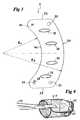
- Fig. 1shows the conditions under which a minimally invasive intra-thoracic surgery is performed: the instruments 2 are introduced into the thorax via incisions of reduced dimensions, without cut-outs of the ribs 3 or the sternum 4.
- Fig. 2shows the retractor of the invention 6 set up for an intervention on a cardiac atrium 8.
- the walls of the heart 10being relatively thin and muscular at the level of the atrium 8, it would be difficult to place spacers there 3.
- the spacer 6consists essentially of a plate 12, made of an elastic material, wound on itself to form the side wall of a truncated cone. . This truncated cone is pushed through an incision 14 inside the atrium 8.
- the reduced section 16 of the truncated conedelimits the surgical field, while the conicity of the wall largely frees the area movement of the surgical instruments and the field of view of the operator which corresponds, in this case, to the field covered by an endoscope 18, placed near the axis of the truncated cone, on the side of its widest section 20.
- Fig. 3shows an embodiment of the spacer 6.
- the elastic plate 12in the absence of stress, adopts a substantially flat shape.
- Its crescent shape amputated by its two hornscorresponds substantially to the side wall of a truncated cone and comprises two sides in an arc of an inner circle 16 of length corresponding to the small section of a truncated cone and radius R1, and an outer side 20 of radius R2 partially corresponding to the circumference of the large section of the truncated cone.
- the large section 20is amputated a portion of its circumference by two substantially parallel sides 22 starting from the ends of the side 16.
- the plate 12is provided, on the side corresponding to the small section of the truncated cone, hooking means 24, 26 cooperating with each other to maintain the retractor in shape as soon as they have been engaged in one another .
- attachment meansare, as shown in FIG. 3, a button 24 and a buttonhole 26 with stop 28, but it goes without saying that other embodiments (staples, snaps, etc.) can be used.
- Several attachment pointscan be provided, which makes it possible to vary the nominal diameter of the spacer according to the size of the organ to be operated.
- Protuberances 32arranged here longitudinally, protrude along the plate. They play an accessory role of stiffener, but their essential function is to avoid an effect of adhesion of the internal walls of the incised member 14 against the continuous surface of the plate 12.
- Fig. 4shows another embodiment of the spacer of the invention.
- useis made of a very long buttonhole 27, also provided with stop means 28, which allows an automatic adaptation of the diameter to the length of the incision.
- stop means 28which allows an automatic adaptation of the diameter to the length of the incision.
- itis possible to significantly reduce the diameter of the spacer in the wound state.
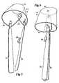
- Figs. 5 and 6provide a better understanding of the role of the gripping means 30 as well as the manner in which the spacer is put in place.
- the operatorhas two elongated positioning instruments 34. Each of these instruments is provided, at its distal end, gripping means 36 (here, a button head 36) adapted to cooperate with the gripper means 30 of the spacer.
- the operatorcan wrap the plate 12 on itself (see Fig. 4).
- the thus-formed rollof small diameter, can easily be inserted into the chest 3, 4 through an incision and placed in the atrium 8.
- the instruments 34are specifically designed to be easily folded and fit therefore at various angles of intervention.
- the positioning tools 34are provided with a fastening clamp 38.
- the presence of this fastening clamp 38facilitates the work as a team, the retractor can pass from hand to hand in the course of intervention without risk of taking place, which saves precious time for the surgeon and the patient.
- the self-elasticity of the plate 12causes the spacer to unfold and adopt the required truncated-conical shape.
- Figs. 7, 8 and 9show another way of introducing the spacer into place.
- the operatoris here calling, rather than the instruments of introduction 34 described above, to conventional locking tongs (or forceps) 40.
- the operatorforces the plate to wind on itself until a cylindrical roll of reduced diameter. It locks the spacer in this position using a locking pliers 40. Finally, it introduces the retractor in place (Fig. 9).
- the spacercan be made of plastics, such as PET or PTFE, and also of a biocompatible metal material such as stainless steel, titanium alloys, etc.
- the retractoras well as the placement instruments 34, available in different standardized sizes, may be either reusable or designed for a single use.
- the spacercan be made of an opaque material, translucent or transparent. However, whatever material is used, it is important that the inner wall minimize reflections that may disturb the operator. For this purpose, this wall can be frosted.
Landscapes
- Health & Medical Sciences (AREA)
- Life Sciences & Earth Sciences (AREA)
- Surgery (AREA)
- Molecular Biology (AREA)
- General Health & Medical Sciences (AREA)
- Biomedical Technology (AREA)
- Heart & Thoracic Surgery (AREA)
- Medical Informatics (AREA)
- Nuclear Medicine, Radiotherapy & Molecular Imaging (AREA)
- Animal Behavior & Ethology (AREA)
- Engineering & Computer Science (AREA)
- Public Health (AREA)
- Veterinary Medicine (AREA)
- Surgical Instruments (AREA)
- Saccharide Compounds (AREA)
- Dental Preparations (AREA)
- Materials For Medical Uses (AREA)
Abstract
Description
Translated fromFrenchL'invention se rapporte aux écarteurs chirurgicaux, et notamment aux écarteurs utilisés dans le domaine de la chirurgie mini- invasive, par exemple pour les opérations dans le domaine cardiaque.The invention relates to surgical retractors, and in particular to retractors used in the field of minimally invasive surgery, for example for operations in the cardiac field.
Les écarteurs sont des instruments destinés à dégager le champ opératoire en écartant les bords d'une incision ou d'un orifice naturel. Ainsi en chirurgie cardiaque classique, l'opérateur dispose d'un champ opératoire relativement large, du fait du recours à la sternotomie. Il en va tout autrement dans le cas de la chirurgie mini-invasive : les voies d'accès sont des incisions de dimensions réduites pratiquées notamment entres les côtes ; l'opérateur ne dispose pas d'une vue directe sur le champ opératoire, mais d'une vue via un endoscope ; les instruments doivent être actionnés à distance dans un espace très réduit et sont donc d'un maniement très différents.The spacers are instruments intended to clear the operative field by spreading the edges of an incision or a natural orifice. Thus in conventional cardiac surgery, the operator has a relatively large operating field, due to the use of sternotomy. The situation is quite different in the case of minimally invasive surgery: the access routes are incisions of reduced dimensions practiced especially between the ribs; the operator does not have a direct view of the operating field, but a view via an endoscope; the instruments must be operated remotely in a very small space and are therefore very differently handled.
On connaît dans le domaine des écarteurs classiques qui affectent la forme de crochets spatulés.Conventional spacers are known in the art which affect the shape of spatulate hooks.
Ce type d'écarteur est d'ailleurs utilisé en chirurgie mini-invasive.This type of retractor is also used in minimally invasive surgery.
Dans le cas de chirurgie intra-thoracique sans sternotomie, il est nécessaire d'exercer une traction de l'extérieur, soit via un opérateur qui maintient l'écarteur au moyen d'un manche, soit pas haubanage aux tissus environnants, ce y compris la cage thoracique, soit par des fils perforant la cage thoracique.
Il existe par ailleurs des écarteurs que l'on peut qualifier d'écarteurs périphériques, utilisés par exemple en chirurgie oculaire (voir
Toutefois, ce type d'écarteur n'est utilisable que dans des opérations ne posant aucun problème d'accessibilité et où la profondeur de champ est réduite. On connaît, de même, par
There are also spacers that can be described as peripheral spacers, used for example in ocular surgery (see
However, this type of spacer can only be used in operations that pose no accessibility problem and where the depth of field is reduced. We also know, by
On a cherché à réaliser un écarteur de faible encombrement, facile à introduire sous une forme compacte, qui permette tant un accès ainsi qu'une vue dégagée d'un champ opératoire réduit.It has been sought to provide a compact retractor, easy to introduce in a compact form, which allows both access and an unobstructed view of a reduced operative field.
L'objet de l'invention est un écarteur chirurgical qui comprend une plaque élastique enroulée sur elle-même autour d'un axe en formant la paroi latérale d'une forme sensiblement tronc-conique. Cette plaque est apte à adopter une forme en substance cylindrique, de diamètre inférieur ou égal à la section réduite de sa forme tronc-conique. Elle comprend des moyens d'accrochage aptes à maintenir la paroi latérale enroulée à un diamètre déterminé. Ces derniers moyens peuvent être, notamment, des boutons-pression, voire un bouton et une boutonnière.The object of the invention is a surgical retractor which comprises an elastic plate wound on itself about an axis forming the side wall of a substantially truncated conical shape. This plate is adapted to adopt a substantially cylindrical shape, of diameter less than or equal to the reduced section of its truncated-conical shape. It comprises hooking means capable of keeping the wound side wall to a determined diameter. These last means may be, in particular, snaps, or even a button and a buttonhole.
Suivant une forme de réalisation, en l'absence de sollicitation, la plaque élastique qui constitue la paroi latérale de la forme tronc-conique adopte spontanément une forme tronc-conique.According to one embodiment, in the absence of stress, the elastic plate which constitutes the wall lateral shape of the truncated-conical form spontaneously adopts a truncated-conical form.
Suivant une autre forme de réalisation, en l'absence de sollicitation, la plaque élastique qui constitue la paroi latérale de la forme tronc-conique adopte spontanément une forme en substance plane. Dans ce cas, la plaque a de préférence une forme sensiblement en croissant tronqué, la courbe intérieure de ce croissant, en arc de cercle, ayant une longueur correspondant au périmètre de la section réduite du tronc de cône, et comprend, en lieu et place des cornes du croissant, deux côtés sensiblement parallèles entre eux, de longueur correspondant à la hauteur du tronc de cône.According to another embodiment, in the absence of stress, the elastic plate which constitutes the side wall of the truncated-conical shape spontaneously adopts a substantially planar shape. In this case, the plate preferably has a substantially truncated crescent shape, the inner curve of this crescent, in an arc, having a length corresponding to the perimeter of the reduced section of the truncated cone, and comprises, in place of crescent horns, two sides substantially parallel to each other, of length corresponding to the height of the truncated cone.
L'écarteur chirurgical de l'invention comprend de préférence des protubérances disposées sur les flancs de la paroi tronc-conique.The surgical retractor of the invention preferably comprises protuberances disposed on the flanks of the truncated-conical wall.
Il comprend avantageusement des moyens de saisie aptes à sa saisie du côté correspondant à la section large de sa forme tronc-conique.It advantageously comprises gripping means capable of grasping the side corresponding to the broad section of its truncated-conical shape.
Ces moyens de saisie sont, de préférence, aptes à coopérer avec des moyens de préhension montés à l'extrémité d'outils de mise en place de forme allongée, les dits outils de mise en place permettant l'enroulement de la plaque et son maintien en position enroulée.These gripping means are preferably capable of cooperating with gripping means mounted at the end of elongated positioning tools, said positioning tools for winding the plate and its retention. in wound position.
Suivant une forme de réalisation avantageuse, ces outils de mise en place comprennent des moyens de liaison permettant de les solidariser entre eux de façon à faciliter leur manipulation, et notamment avec l'écarteur maintenu en position enroulée.According to an advantageous embodiment, these positioning tools comprise connecting means for securing them to each other so as to facilitate their handling, and in particular with the spacer held in the wound position.
La face interne de l'écarteur chirurgical selon l'invention est traitée, de préférence, de façon à éviter les reflets parasites. Elle peut ainsi être réalisée en un matériau dépoli, qui peut être du métal ou une matière plastique, de façon à éviter de tels reflets.The inner face of the surgical retractor according to the invention is treated, preferably, so as to avoid parasitic reflections. It can thus be made of a frosted material, which may be metal or a plastic material, so as to avoid such reflections.
Ces aspects ainsi que d'autres aspects de l'invention seront clarifiés dans la description détaillée de modes de réalisation particuliers de l'invention, référence étant faite aux dessins des figures, dans lesquelles :
- La Fig.1 est une vue schématique en perspective, avec arrachement, d'une intervention intra-thoracique mini-invasive typique.
- La Fig.2 est une vue en perspective d'un écarteur suivant l'invention mis en place dans une oreillette d'un coeur.
- La Fig.3 est une vue en plan d'un écarteur suivant l'invention étalé à plat.
- La Fig.4 est une vue en plan d'un autre mode de réalisation d'un écarteur suivant l'invention étalé à plat.
- Les Fig. 4 et 5 sont des vues en perspective d'instruments de manipulation d'un écarteur suivant l'invention, maintenant l'écarteur respectivement déployé et enroulé sous forme compacte pour l'introduction.
- Les Fig. 6, 7 et 8 sont des vues en perspective de l'écarteur de la Fig. 4 à différents stades de manipulation.
- Fig.1 is a schematic perspective view, with cutaway, of a typical intrathoracic minimally invasive procedure.
- Fig.2 is a perspective view of a spacer according to the invention set up in an atrium of a heart.
- Fig.3 is a plan view of a spacer according to the invention spread flat.
- Fig.4 is a plan view of another embodiment of a spacer according to the invention spread flat.
- Figs. 4 and 5 are perspective views of instruments for handling a spacer according to the invention, maintaining the spacer respectively deployed and wound in compact form for introduction.
- Figs. 6, 7 and 8 are perspective views of the spacer of FIG. 4 at different stages of handling.
Les figures ne sont pas dessinées à l'échelle. Généralement, des éléments semblables sont dénotés par des références semblables dans les figures. La présente invention sera décrite dans le cadre de modes de réalisations spécifiques, choisis à titre illustratifs et non limitatifsThe figures are not drawn to scale. Generally, similar elements are denoted by similar references in the figures. The present invention will be described in the context of specific achievements, chosen for illustrative and non-limiting purposes
La Fig. 1 montre les conditions dans lesquelles on pratique une chirurgie intra-thoracique mini-invasive : les instruments 2 sont introduits à l'intérieur du thorax via des incisions de dimensions réduites, sans découpes des côtes 3 ou du sternum 4.Fig. 1 shows the conditions under which a minimally invasive intra-thoracic surgery is performed: the
La Fig. 2 montre l'écarteur de l'invention 6 mis en place pour une intervention sur une oreillette cardiaque 8. Les parois du coeur 10 étant relativement minces et peu musculeuses au niveau de l'oreillette 8, il serait délicat d'y placer des écarteurs classiques amarrés à la cage thoracique 3. Comme on le voit, l'écarteur 6 est constitué essentiellement d'une plaque 12, réalisée en un matériau élastique, enroulée sur elle-même de façon à former la paroi latérale d'un tronc du cône. Ce tronc de cône est enfoncé, au-travers d'une incision 14, à l'intérieur de l'oreillette 8. La section réduite 16 du tronc de cône délimite le champ opératoire, cependant que la conicité de la paroi dégage largement la zone de déplacement des instruments chirurgicaux et le champ visuel de l'opérateur qui correspond, en l'occurrence, au champ couvert par un endoscope 18, placé près de l'axe du tronc de cône, du côté de sa section la plus large 20.Fig. 2 shows the retractor of the
La Fig. 3 montre une forme de réalisation de l'écarteur 6. Dans cette forme de réalisation, la plaque 12, élastique, en l'absence de sollicitation, adopte une forme sensiblement plane. Sa forme en croissant amputé de ses deux cornes correspond sensiblement à la paroi latérale d'un tronc de cône et comprend deux côtés en arc de cercle: un côté intérieur 16 de longueur correspondant à la petite section d'un tronc de cône et de rayon R1, et un côté extérieur 20 de rayon R2 correspondant partiellement à la circonférence de la grande section du tronc de cône. Comme on peut le voir à la Fig. 3, la grande section 20 est amputée d'une partie de sa circonférence par deux côtés 22 sensiblement parallèles partant des extrémités du coté 16.Fig. 3 shows an embodiment of the
La plaque 12 est munie, du côté correspondant à la petite section du tronc de cône, de moyens d'accrochage 24, 26 coopérant entre eux pour maintenir l'écarteur en forme dès qu'ils ont été engagés l'un dans l'autre.The
Ces moyens d'accrochage sont, comme représentés à la Fig. 3, un bouton 24 et une boutonnière 26 avec arrêt 28, mais il va de soi que d'autres modes de réalisations (agrafes, boutons-pression, etc.) peuvent être utilisés. On peut prévoir plusieurs points d'accrochage, ce qui permet de faire varier le diamètre nominal de l'écarteur en fonction de la taille de l'organe à opérer.These attachment means are, as shown in FIG. 3, a
Près des deux extrémités du côté correspondant à la circonférence de la grande section du tronc de cône sont visibles des moyens de saisie 30, en l'occurrence des ouvertures 30. Leur rôle sera expliqué plus loin.Near both ends of the side corresponding to the circumference of the large section of the truncated cone are visible input means 30, in this
Des protubérances 32, disposées ici longitudinalement, font saillie le long de la plaque. Elles jouent un rôle accessoire de raidisseur, mais leur fonction essentielle est d'éviter un effet d'adhérence des parois internes de l'organe incisé 14 contre la surface continue de la plaque 12.
La Fig. 4 montre un autre mode de réalisation de l'écarteur de l'invention. Dans ce mode de réalisation, on fait appel à une très longue boutonnière 27, également munie de moyens d'arrêts 28, ce qui permet une adaptation automatique du diamètre à la longueur de l'incision. En outre, on peut ainsi réduire de façon importante le diamètre de l'écarteur à l'état enroulé.Fig. 4 shows another embodiment of the spacer of the invention. In this embodiment, use is made of a very
Les Fig. 5 et 6 permettent de mieux comprendre le rôle des moyens de saisie 30 ainsi que la façon dont l'écarteur est mis en place. Pour insérer l'écarteur 6 à l'intérieur de la cage thoracique 3, 4, l'opérateur dispose de deux instruments de mise en place 34 de forme allongée. Chacun de ces instruments est muni, à son extrémité distale, de moyens de préhension 36 (ici, une tête en bouton 36) aptes à coopérer avec les moyens de saisie 30 de l'écarteur.Figs. 5 and 6 provide a better understanding of the role of the gripping means 30 as well as the manner in which the spacer is put in place. To insert the
En manipulant les deux instruments 34, l'opérateur peut enrouler sur elle-même la plaque 12 (voir Fig. 4). Le rouleau ainsi formé, de faible diamètre, peut aisément être inséré dans le thorax 3, 4 au-travers d'une incision et mis en place dans l'oreillette 8. Les instruments 34 sont spécifiquement conçus pour être facilement pliés et s'adaptent donc à divers angles d'interventions.By manipulating the two
Pour éviter que la plaque 12 ne se déroule par inadvertance et pour permettre leur manipulation d'une seule main, les outils de mise en place 34 sont munis d'une pince de solidarisation 38. La présence de cette pince de solidarisation 38 facilite le travail en équipe, l'écarteur pouvant passer de main en main en cours d'intervention sans risque de se dérouler, d'où un gain de temps précieux pour le chirurgien et le patient.
Aussitôt que les outils de mise en place 34 sont désolidarisés, l'élasticité propre de la plaque 12 contraint l'écarteur à se déplier et à adopter la forme tronc-conique requise.To prevent the
As soon as the
Les Fig. 7, 8 et 9 montrent une autre façon d'introduire l'écarteur en place. L'opérateur fait ici appel, plutôt qu'aux instruments de mise en place 34 décrits plus haut, à des pinces à verrouillage (ou forceps) 40 classiques.Figs. 7, 8 and 9 show another way of introducing the spacer into place. The operator is here calling, rather than the instruments of
A la Fig. 7, l'opérateur enroule la plaque sur elle - même et verrouille l'écarteur en position grossièrement tronc-conique à l'aide des moyens d'accrochage.In FIG. 7, the operator winds the plate on itself and locks the spacer in a roughly truncated conical position using the hooking means.
A la Fig. 8, l'opérateur force la plaque à s'enrouler sur elle-même jusqu'à obtention d'un rouleau cylindrique de diamètre réduit. Il verrouille l'écarteur dans cette position à l'aide d'une pince à verrouillage 40. Il introduit enfin l'écarteur en place (Fig. 9). On remarquera que la forme sensiblement plane de la plaque élastique 12 permet un stockage à plat, particulièrement peu encombrant, et évite tout fluage dans le cas où la plaque est réalisée en matériaux sensibles à ce phénomène. On peut réaliser l'écarteur en matières plastiques, tels que le PET ou le PTFE, et également en un matériau métallique bio-compatible tel que l'acier inoxydable, les alliages de Titane etc.In FIG. 8, the operator forces the plate to wind on itself until a cylindrical roll of reduced diameter. It locks the spacer in this position using a locking
L'écarteur, de même que les instruments de mise en place 34, décliné en différentes dimensions standardisées, peut être, soit réutilisable, soit conçu pour un seul usage.The retractor, as well as the
Les avantages lié à la forme dépliée plane n'empêchent cependant pas de réaliser un écarteur suivant la présente invention présentant, en l'absence de sollicitations, une forme au repos tronc-conique. Cependant, même réalisé sous une telle forme, il est préférable de le doter de moyens d'accrochage, afin que la pression des tissus ne le force à se réenrouler partiellement au cours de l'opération.The advantages associated with the flat unfolded shape do not, however, prevent a retractor according to the present invention having, in the absence of stresses, a truncated-conical shape at rest. However, even made in such a form, it is preferable to provide it with attachment means, so that the tissue pressure does not force it to rewind partially during the operation.
L'écarteur peut être réalisé en un matériau opaque, translucide ou transparent. Cependant, quel que soit le matériau utilisé, il est important que la paroi intérieure réduise au maximum les reflets susceptibles de perturber l'opérateur. A cet effet, cette paroi peut être dépolie.The spacer can be made of an opaque material, translucent or transparent. However, whatever material is used, it is important that the inner wall minimize reflections that may disturb the operator. For this purpose, this wall can be frosted.
Les différentes opérations de l'emploi de l'écarteur suivant l'invention peuvent donc se résumer ainsi :
- prévoir une plaque en un matériau élastique apte à adopter une forme sensiblement tronc-conique;
- amener ladite plaque à sa forme tronc-conique;
- saisir ladite plaque du côté de son grand diamètre et l'enrouler sur elle-même de façon à former un cylindre de diamètre réduit;
- passer l'écarteur au-travers de l'incision;
- laisser l'écarteur se dérouler de façon à ce qu'il reprenne sa forme tronc-conique.
- provide a plate of an elastic material adapted to adopt a substantially truncated conical shape;
- bringing said plate to its truncated conical shape;
- grasping said plate on the side of its large diameter and winding it on itself so as to form a cylinder of reduced diameter;
- pass the retractor through the incision;
- let the spreader unfold so that it resumes its truncated-conical shape.
Il apparaîtra évident pour l'homme du métier que la présente invention n'est pas limitée à ce qui a été décrit ci-dessus. L'invention réside également dans chacune des caractéristiques nouvelles et dans la combinaison entre elles de ces différentes caractéristiques.It will be apparent to those skilled in the art that the present invention is not limited to what has been described above. The invention also resides in each of the new features and in the combination of these different characteristics.
Claims (10)
Translated fromFrenchcaractérisé en ce qu'il comprend
une plaque élastique (12) enroulée sur elle-même autour d'un axe en formant la paroi latérale d'une forme sensiblement tronc-conique, la dite plaque (12) étant apte à adapter une forme en substance cylindrique de diamètre inférieur ou égal à la section réduite de sa forme tronc-conique et comprenant des moyens d'accrochage (24, 26) aptes à maintenir la paroi latérale tronc-conique enroulée à un diamètre déterminé.Surgical retractor
characterized in that it comprises
an elastic plate (12) wound on itself about an axis forming the side wall of a substantially truncated conical shape, said plate (12) being adapted to adapt a substantially cylindrical shape of diameter less than or equal to the reduced section of its truncated-conical shape and comprising attachment means (24, 26) able to maintain the truncated-conical side wall wound to a determined diameter.
caractérisé en ce qu'en l'absence de sollicitation, la plaque élastique (12) qui constitue la paroi latérale de la forme tronc-conique adopte spontanément une forme tronc-conique.Surgical retractor according to claim 1,
characterized in that in the absence of stress, the elastic plate (12) which constitutes the side wall of the truncated-conical shape spontaneously adopts a truncated-conical shape.
caractérisé en ce que, en l'absence de sollicitation, la plaque élastique (12) qui constitue la paroi latérale de la forme tronc-conique adopte spontanément une forme en substance plane.Surgical retractor according to claim 1,
characterized in that , in the absence of stress, the elastic plate (12) which constitutes the side wall of the truncated-conical shape spontaneously adopts a substantially planar shape.
caractérisé en ce que les moyens de saisie (30) sont aptes à coopérer avec des moyens de préhension (36) montés à l'extrémité d'outils de mise en place (34) de forme allongée, les dits outils de mise en place (34) permettant l'enroulement de la plaque (12).Surgical retractor according to claim 7,
characterized in that the gripping means (30) are adapted to cooperate with gripping means (36) mounted at the end of elongated positioning tools (34), the so-called setting tools ( 34) for winding the plate (12).
Priority Applications (12)
| Application Number | Priority Date | Filing Date | Title |
|---|---|---|---|
| EP05107376AEP1752106A1 (en) | 2005-08-11 | 2005-08-11 | Surgical retractor |
| PL06708717TPL1912576T3 (en) | 2005-08-11 | 2006-03-10 | Surgical retractor |
| CN2006800286869ACN101237826B (en) | 2005-08-11 | 2006-03-10 | Surgical retractor |
| CA002618197ACA2618197A1 (en) | 2005-08-11 | 2006-03-10 | Surgical retractor |
| PCT/EP2006/060618WO2007017294A1 (en) | 2005-08-11 | 2006-03-10 | Surgical retractor |
| DE602006005935TDE602006005935D1 (en) | 2005-08-11 | 2006-03-10 | SURGICAL RETRACTOR |
| US11/372,520US7871374B2 (en) | 2005-08-11 | 2006-03-10 | Surgical retractor |
| JP2008525498AJP4994376B2 (en) | 2005-08-11 | 2006-03-10 | Surgical retractor |
| ES06708717TES2324311T3 (en) | 2005-08-11 | 2006-03-10 | SURGICAL RETRACTOR. |
| EP06708717AEP1912576B1 (en) | 2005-08-11 | 2006-03-10 | Surgical retractor |
| AT06708717TATE426364T1 (en) | 2005-08-11 | 2006-03-10 | SURGICAL RETRACTOR |
| BRPI0615007-1ABRPI0615007A2 (en) | 2005-08-11 | 2006-03-10 | surgical retractor |
Applications Claiming Priority (1)
| Application Number | Priority Date | Filing Date | Title |
|---|---|---|---|
| EP05107376AEP1752106A1 (en) | 2005-08-11 | 2005-08-11 | Surgical retractor |
Publications (1)
| Publication Number | Publication Date |
|---|---|
| EP1752106A1true EP1752106A1 (en) | 2007-02-14 |
Family
ID=35335769
Family Applications (2)
| Application Number | Title | Priority Date | Filing Date |
|---|---|---|---|
| EP05107376AWithdrawnEP1752106A1 (en) | 2005-08-11 | 2005-08-11 | Surgical retractor |
| EP06708717ANot-in-forceEP1912576B1 (en) | 2005-08-11 | 2006-03-10 | Surgical retractor |
Family Applications After (1)
| Application Number | Title | Priority Date | Filing Date |
|---|---|---|---|
| EP06708717ANot-in-forceEP1912576B1 (en) | 2005-08-11 | 2006-03-10 | Surgical retractor |
Country Status (11)
| Country | Link |
|---|---|
| US (1) | US7871374B2 (en) |
| EP (2) | EP1752106A1 (en) |
| JP (1) | JP4994376B2 (en) |
| CN (1) | CN101237826B (en) |
| AT (1) | ATE426364T1 (en) |
| BR (1) | BRPI0615007A2 (en) |
| CA (1) | CA2618197A1 (en) |
| DE (1) | DE602006005935D1 (en) |
| ES (1) | ES2324311T3 (en) |
| PL (1) | PL1912576T3 (en) |
| WO (1) | WO2007017294A1 (en) |
Cited By (1)
| Publication number | Priority date | Publication date | Assignee | Title |
|---|---|---|---|---|
| FR2980355A1 (en)* | 2011-09-26 | 2013-03-29 | Delacroix Chevalier | Surgical spacer device i.e. offset bracket for maintaining incision during invasive microsurgery on e.g. lung, has strip including free end passed through opening of tensioner to form ring having minimum outer diameter and maximum opening |
Families Citing this family (27)
| Publication number | Priority date | Publication date | Assignee | Title |
|---|---|---|---|---|
| US20080033251A1 (en)* | 2006-06-30 | 2008-02-07 | Ali Araghi | Surgical retractor and method of use |
| US20080183044A1 (en)* | 2007-01-26 | 2008-07-31 | Dennis Colleran | Flexible surgical retractor and method of use |
| US8062217B2 (en)* | 2007-01-26 | 2011-11-22 | Theken Spine, Llc | Surgical retractor with removable blades and method of use |
| CN102014770A (en) | 2008-04-23 | 2011-04-13 | 约翰·霍普金斯大学 | Contoured elastomeric barrier for bowel retention and method of use |
| EP2165651B1 (en)* | 2008-09-19 | 2011-08-17 | Sorin Biomedica Cardio S.R.L. | Surgical tool for vascular exposure and access |
| US8137267B2 (en)* | 2009-04-08 | 2012-03-20 | Ethicon Endo-Surgery, Inc. | Retractor with flexible sleeve |
| US20100305407A1 (en)* | 2009-06-02 | 2010-12-02 | Farley Daniel K | Malleable Port Retractor |
| US8979748B2 (en)* | 2009-10-23 | 2015-03-17 | James L. Chappuis | Devices and methods for temporarily retaining spinal rootlets within dural sac |
| US8388525B2 (en)* | 2009-12-09 | 2013-03-05 | Miami Instruments Llc | Atrial lift retractor |
| WO2011099553A1 (en)* | 2010-02-12 | 2011-08-18 | 株式会社メディカル・パイン | Rib spreader |
| US8721538B2 (en)* | 2010-05-10 | 2014-05-13 | St. Louis University | Distractor |
| US20120088960A1 (en)* | 2010-10-12 | 2012-04-12 | Kubisen Steven J | Bowel packing device having a tether |
| USD664651S1 (en)* | 2010-12-23 | 2012-07-31 | Karl Storz Gmbh & Co. Kg | Atrium retractor |
| USD664652S1 (en)* | 2010-12-23 | 2012-07-31 | Karl Storz Gmbh & Co. Kg | Atrium retractor |
| US9119665B2 (en)* | 2011-03-21 | 2015-09-01 | Covidien Lp | Thoracic access port including foldable anchor |
| DE102012001500B4 (en) | 2012-01-27 | 2019-04-25 | Cardiomedical Gmbh | Surgical retractor |
| US9375200B2 (en)* | 2013-03-12 | 2016-06-28 | Siemens Medical Solutions Usa, Inc. | Ultrasound transducer with differential mode signaling |
| DE102013205519B4 (en) | 2013-03-27 | 2019-05-23 | Fehling Instruments Gmbh & Co. Kg | Spreader for the atrium of the heart |
| JP6328950B2 (en)* | 2014-02-19 | 2018-05-23 | 日機装株式会社 | Surgical area securing device |
| JP6292141B2 (en)* | 2015-01-29 | 2018-03-14 | 独立行政法人国立病院機構 | Retractor |
| KR102008130B1 (en)* | 2016-07-25 | 2019-08-06 | 고우리쯔 다이가쿠 호오진 오사카 시리쯔 다이가쿠 | Small incision under light surgery |
| AU2017324450B2 (en)* | 2016-09-12 | 2022-09-29 | Applied Medical Resources Corporation | Surgical robotic access system for irregularly shaped robotic actuators and associated robotic surgical instruments |
| US9928813B1 (en)* | 2017-06-26 | 2018-03-27 | Andrew M. Washburn | Rollable and adjustable mute for brass instruments |
| JP7235776B2 (en) | 2018-06-12 | 2023-03-08 | テルモ カーディオバスキュラー システムズ コーポレイション | Circular retractor for cardiovascular valve procedures |
| IT201800007267A1 (en)* | 2018-07-17 | 2020-01-17 | Tissue retractor for the retraction of incisions | |
| CN111789642B (en)* | 2020-07-02 | 2023-06-20 | 泰升医疗有限公司 | Retractor components and retractors |
| US11826036B2 (en) | 2021-12-03 | 2023-11-28 | Lsi Solutions, Inc. | Epigastric retractor |
Citations (5)
| Publication number | Priority date | Publication date | Assignee | Title |
|---|---|---|---|---|
| US5342385A (en) | 1991-02-05 | 1994-08-30 | Norelli Robert A | Fluid-expandable surgical retractor |
| US6083155A (en) | 1999-04-16 | 2000-07-04 | Nuvue Technologies, L.L.C. | Eyelid speculum |
| US20030191371A1 (en)* | 2002-04-05 | 2003-10-09 | Smith Maurice M. | Devices and methods for percutaneous tissue retraction and surgery |
| WO2004021899A1 (en)* | 2002-09-05 | 2004-03-18 | Endius Incorporated | System and methods for performing minimally-invasive surgical procedures |
| US20040116954A1 (en)* | 1998-08-20 | 2004-06-17 | Endius Inc. | Surgical tool for use in expanding a cannula |
Family Cites Families (9)
| Publication number | Priority date | Publication date | Assignee | Title |
|---|---|---|---|---|
| US2605582A (en)* | 1946-07-24 | 1952-08-05 | Raney R Allen | Inlet tube for use in bait traps |
| US5255678A (en)* | 1991-06-21 | 1993-10-26 | Ecole Polytechnique | Mapping electrode balloon |
| US5630813A (en)* | 1994-12-08 | 1997-05-20 | Kieturakis; Maciej J. | Electro-cauterizing dissector and method for facilitating breast implant procedure |
| US6063155A (en)* | 1998-04-06 | 2000-05-16 | Orinoco Iron, C.A. | Fluidized bed process for the production of iron carbide |
| DE69920896T2 (en)* | 1998-04-23 | 2005-11-17 | Boston Scientific Ltd., St. Michael | MEDICAL DEVICE WHICH ENABLES ACCESS TO THE BODY |
| US6652553B2 (en)* | 1998-08-20 | 2003-11-25 | Endius Incorporated | Surgical tool for use in expanding a cannula |
| US7144393B2 (en)* | 2001-05-15 | 2006-12-05 | Dipoto Gene P | Structure for receiving surgical instruments |
| US6945933B2 (en)* | 2002-06-26 | 2005-09-20 | Sdgi Holdings, Inc. | Instruments and methods for minimally invasive tissue retraction and surgery |
| CN1254217C (en)* | 2004-02-26 | 2006-05-03 | 上海交通大学 | Radio frequency ablation electrode for treating auricular fibrillation |
- 2005
- 2005-08-11EPEP05107376Apatent/EP1752106A1/ennot_activeWithdrawn
- 2006
- 2006-03-10DEDE602006005935Tpatent/DE602006005935D1/enactiveActive
- 2006-03-10ATAT06708717Tpatent/ATE426364T1/ennot_activeIP Right Cessation
- 2006-03-10EPEP06708717Apatent/EP1912576B1/ennot_activeNot-in-force
- 2006-03-10BRBRPI0615007-1Apatent/BRPI0615007A2/ennot_activeIP Right Cessation
- 2006-03-10CNCN2006800286869Apatent/CN101237826B/ennot_activeExpired - Fee Related
- 2006-03-10ESES06708717Tpatent/ES2324311T3/enactiveActive
- 2006-03-10JPJP2008525498Apatent/JP4994376B2/ennot_activeExpired - Fee Related
- 2006-03-10USUS11/372,520patent/US7871374B2/ennot_activeExpired - Fee Related
- 2006-03-10PLPL06708717Tpatent/PL1912576T3/enunknown
- 2006-03-10WOPCT/EP2006/060618patent/WO2007017294A1/enactiveApplication Filing
- 2006-03-10CACA002618197Apatent/CA2618197A1/ennot_activeAbandoned
Patent Citations (5)
| Publication number | Priority date | Publication date | Assignee | Title |
|---|---|---|---|---|
| US5342385A (en) | 1991-02-05 | 1994-08-30 | Norelli Robert A | Fluid-expandable surgical retractor |
| US20040116954A1 (en)* | 1998-08-20 | 2004-06-17 | Endius Inc. | Surgical tool for use in expanding a cannula |
| US6083155A (en) | 1999-04-16 | 2000-07-04 | Nuvue Technologies, L.L.C. | Eyelid speculum |
| US20030191371A1 (en)* | 2002-04-05 | 2003-10-09 | Smith Maurice M. | Devices and methods for percutaneous tissue retraction and surgery |
| WO2004021899A1 (en)* | 2002-09-05 | 2004-03-18 | Endius Incorporated | System and methods for performing minimally-invasive surgical procedures |
Cited By (1)
| Publication number | Priority date | Publication date | Assignee | Title |
|---|---|---|---|---|
| FR2980355A1 (en)* | 2011-09-26 | 2013-03-29 | Delacroix Chevalier | Surgical spacer device i.e. offset bracket for maintaining incision during invasive microsurgery on e.g. lung, has strip including free end passed through opening of tensioner to form ring having minimum outer diameter and maximum opening |
Also Published As
| Publication number | Publication date |
|---|---|
| DE602006005935D1 (en) | 2009-05-07 |
| JP4994376B2 (en) | 2012-08-08 |
| US7871374B2 (en) | 2011-01-18 |
| EP1912576B1 (en) | 2009-03-25 |
| JP2009504214A (en) | 2009-02-05 |
| BRPI0615007A2 (en) | 2011-05-03 |
| ATE426364T1 (en) | 2009-04-15 |
| CN101237826B (en) | 2010-10-13 |
| PL1912576T3 (en) | 2009-09-30 |
| US20070038032A1 (en) | 2007-02-15 |
| CN101237826A (en) | 2008-08-06 |
| EP1912576A1 (en) | 2008-04-23 |
| ES2324311T3 (en) | 2009-08-04 |
| CA2618197A1 (en) | 2007-02-15 |
| WO2007017294A1 (en) | 2007-02-15 |
Similar Documents
| Publication | Publication Date | Title |
|---|---|---|
| EP1752106A1 (en) | Surgical retractor | |
| CA2307735C (en) | Multipurpose catheter | |
| EP0621007B1 (en) | Ligaturing and/or suturing system for endoscopic sugery | |
| EP1827260B1 (en) | Perforating trocar | |
| EP3256055B1 (en) | Surgical staple having two movable arms connected by a transverse connection area | |
| WO2011007062A1 (en) | Surgical device for expanding and positioning a therapeutic tissue, in particular a hernia prosthesis, by coelioscopy | |
| WO2010100338A1 (en) | Microsurgery clamp, in particular microincision capsulorhexis clamp | |
| FR2827756A1 (en) | Snare and associated applicators used in endoscopic surgery comprises bandage circumscribing esophagus to form closed loop | |
| EP1778097B1 (en) | Parietal anchoring tool and device, in particular for laparoscopic or coelioscopic surgery | |
| EP3509503B1 (en) | Endoscopic needle carrier | |
| LU100245B1 (en) | Apparatus for storing and inserting an intraocular lens | |
| EP3958754B1 (en) | Device for the treatment of haemorrhoidal disease | |
| FR3032608A1 (en) | ENDOSCOPIC SURGERY SYSTEM FORMED ON ONE PART BY A PLURALITY OF STAPLES AND ON THE OTHER BY AN ENDOSCOPIC APPLICATOR. | |
| EP3565485B1 (en) | Surgical staple having two movable branches connected by a transverse connecting zone | |
| EP2938285B1 (en) | Assembly including at least one implant and a gripping device, and method of preparation for the firring of he implant of an assembly of the aforementioned type | |
| EP0974375B1 (en) | Balloon device with nominally adjustable diameter | |
| FR2908034A1 (en) | Laparoscopic retractor for use in e.g. laparoscopic device, has return device with control unit to control return elements constituted of thumb wheel arranged on handle and arranged to cooperate with threaded rod | |
| FR3138766A1 (en) | Surgical suture system including improved cap | |
| CN213821692U (en) | Hysteroscopic tissue snare | |
| WO2002064326A1 (en) | Scissors with interchangeable blades | |
| FR2846868A1 (en) | Removable anvil support for stapler comprises first long part with removable connection to stapler and second long part with connection to anvil | |
| FR2546736A1 (en) | Surgical instrument for curving and calibrating pins | |
| EP4018961A1 (en) | Guiding device for the installation of a maxillofacial-zygomatic implant | |
| FR3092487A1 (en) | ARTICULATED OBSTETRICAL SPATULA | |
| EP3763297A1 (en) | Bone anchoring device |
Legal Events
| Date | Code | Title | Description |
|---|---|---|---|
| PUAI | Public reference made under article 153(3) epc to a published international application that has entered the european phase | Free format text:ORIGINAL CODE: 0009012 | |
| AK | Designated contracting states | Kind code of ref document:A1 Designated state(s):AT BE BG CH CY CZ DE DK EE ES FI FR GB GR HU IE IS IT LI LT LU LV MC NL PL PT RO SE SI SK TR | |
| AX | Request for extension of the european patent | Extension state:AL BA HR MK YU | |
| AKX | Designation fees paid | ||
| REG | Reference to a national code | Ref country code:DE Ref legal event code:8566 | |
| STAA | Information on the status of an ep patent application or granted ep patent | Free format text:STATUS: THE APPLICATION IS DEEMED TO BE WITHDRAWN | |
| 18D | Application deemed to be withdrawn | Effective date:20070815 |