EP1751631B1 - Markup language-based, dynamic process graphics in a process plant user interface - Google Patents
Markup language-based, dynamic process graphics in a process plant user interfaceDownload PDFInfo
- Publication number
- EP1751631B1 EP1751631B1EP05745149AEP05745149AEP1751631B1EP 1751631 B1EP1751631 B1EP 1751631B1EP 05745149 AEP05745149 AEP 05745149AEP 05745149 AEP05745149 AEP 05745149AEP 1751631 B1EP1751631 B1EP 1751631B1
- Authority
- EP
- European Patent Office
- Prior art keywords
- user interface
- graphic display
- graphics
- display
- graphic
- Prior art date
- Legal status (The legal status is an assumption and is not a legal conclusion. Google has not performed a legal analysis and makes no representation as to the accuracy of the status listed.)
- Ceased
Links
Images


Classifications
- G—PHYSICS
- G05—CONTROLLING; REGULATING
- G05B—CONTROL OR REGULATING SYSTEMS IN GENERAL; FUNCTIONAL ELEMENTS OF SUCH SYSTEMS; MONITORING OR TESTING ARRANGEMENTS FOR SUCH SYSTEMS OR ELEMENTS
- G05B19/00—Programme-control systems
- G05B19/02—Programme-control systems electric
- G05B19/04—Programme control other than numerical control, i.e. in sequence controllers or logic controllers
- G05B19/042—Programme control other than numerical control, i.e. in sequence controllers or logic controllers using digital processors
- G05B19/0426—Programming the control sequence
- G—PHYSICS
- G05—CONTROLLING; REGULATING
- G05B—CONTROL OR REGULATING SYSTEMS IN GENERAL; FUNCTIONAL ELEMENTS OF SUCH SYSTEMS; MONITORING OR TESTING ARRANGEMENTS FOR SUCH SYSTEMS OR ELEMENTS
- G05B19/00—Programme-control systems
- G05B19/02—Programme-control systems electric
- G—PHYSICS
- G05—CONTROLLING; REGULATING
- G05B—CONTROL OR REGULATING SYSTEMS IN GENERAL; FUNCTIONAL ELEMENTS OF SUCH SYSTEMS; MONITORING OR TESTING ARRANGEMENTS FOR SUCH SYSTEMS OR ELEMENTS
- G05B19/00—Programme-control systems
- G05B19/02—Programme-control systems electric
- G05B19/04—Programme control other than numerical control, i.e. in sequence controllers or logic controllers
- G05B19/042—Programme control other than numerical control, i.e. in sequence controllers or logic controllers using digital processors
- G05B19/0423—Input/output
- G05B19/0425—Safety, monitoring
- G—PHYSICS
- G05—CONTROLLING; REGULATING
- G05B—CONTROL OR REGULATING SYSTEMS IN GENERAL; FUNCTIONAL ELEMENTS OF SUCH SYSTEMS; MONITORING OR TESTING ARRANGEMENTS FOR SUCH SYSTEMS OR ELEMENTS
- G05B19/00—Programme-control systems
- G05B19/02—Programme-control systems electric
- G05B19/04—Programme control other than numerical control, i.e. in sequence controllers or logic controllers
- G05B19/042—Programme control other than numerical control, i.e. in sequence controllers or logic controllers using digital processors
- G05B19/0428—Safety, monitoring
- G—PHYSICS
- G05—CONTROLLING; REGULATING
- G05B—CONTROL OR REGULATING SYSTEMS IN GENERAL; FUNCTIONAL ELEMENTS OF SUCH SYSTEMS; MONITORING OR TESTING ARRANGEMENTS FOR SUCH SYSTEMS OR ELEMENTS
- G05B19/00—Programme-control systems
- G05B19/02—Programme-control systems electric
- G05B19/418—Total factory control, i.e. centrally controlling a plurality of machines, e.g. direct or distributed numerical control [DNC], flexible manufacturing systems [FMS], integrated manufacturing systems [IMS] or computer integrated manufacturing [CIM]
- G05B19/4185—Total factory control, i.e. centrally controlling a plurality of machines, e.g. direct or distributed numerical control [DNC], flexible manufacturing systems [FMS], integrated manufacturing systems [IMS] or computer integrated manufacturing [CIM] characterised by the network communication
- G—PHYSICS
- G05—CONTROLLING; REGULATING
- G05B—CONTROL OR REGULATING SYSTEMS IN GENERAL; FUNCTIONAL ELEMENTS OF SUCH SYSTEMS; MONITORING OR TESTING ARRANGEMENTS FOR SUCH SYSTEMS OR ELEMENTS
- G05B19/00—Programme-control systems
- G05B19/02—Programme-control systems electric
- G05B19/418—Total factory control, i.e. centrally controlling a plurality of machines, e.g. direct or distributed numerical control [DNC], flexible manufacturing systems [FMS], integrated manufacturing systems [IMS] or computer integrated manufacturing [CIM]
- G05B19/41885—Total factory control, i.e. centrally controlling a plurality of machines, e.g. direct or distributed numerical control [DNC], flexible manufacturing systems [FMS], integrated manufacturing systems [IMS] or computer integrated manufacturing [CIM] characterised by modeling, simulation of the manufacturing system
- G—PHYSICS
- G05—CONTROLLING; REGULATING
- G05B—CONTROL OR REGULATING SYSTEMS IN GENERAL; FUNCTIONAL ELEMENTS OF SUCH SYSTEMS; MONITORING OR TESTING ARRANGEMENTS FOR SUCH SYSTEMS OR ELEMENTS
- G05B23/00—Testing or monitoring of control systems or parts thereof
- G05B23/02—Electric testing or monitoring
- G05B23/0205—Electric testing or monitoring by means of a monitoring system capable of detecting and responding to faults
- G05B23/0259—Electric testing or monitoring by means of a monitoring system capable of detecting and responding to faults characterized by the response to fault detection
- G05B23/0267—Fault communication, e.g. human machine interface [HMI]
- G—PHYSICS
- G06—COMPUTING OR CALCULATING; COUNTING
- G06F—ELECTRIC DIGITAL DATA PROCESSING
- G06F11/00—Error detection; Error correction; Monitoring
- G06F11/30—Monitoring
- G06F11/32—Monitoring with visual or acoustical indication of the functioning of the machine
- G—PHYSICS
- G06—COMPUTING OR CALCULATING; COUNTING
- G06F—ELECTRIC DIGITAL DATA PROCESSING
- G06F13/00—Interconnection of, or transfer of information or other signals between, memories, input/output devices or central processing units
- G—PHYSICS
- G06—COMPUTING OR CALCULATING; COUNTING
- G06F—ELECTRIC DIGITAL DATA PROCESSING
- G06F13/00—Interconnection of, or transfer of information or other signals between, memories, input/output devices or central processing units
- G06F13/38—Information transfer, e.g. on bus
- G06F13/382—Information transfer, e.g. on bus using universal interface adapter
- G06F13/387—Information transfer, e.g. on bus using universal interface adapter for adaptation of different data processing systems to different peripheral devices, e.g. protocol converters for incompatible systems, open system
- G—PHYSICS
- G06—COMPUTING OR CALCULATING; COUNTING
- G06F—ELECTRIC DIGITAL DATA PROCESSING
- G06F16/00—Information retrieval; Database structures therefor; File system structures therefor
- G—PHYSICS
- G06—COMPUTING OR CALCULATING; COUNTING
- G06F—ELECTRIC DIGITAL DATA PROCESSING
- G06F8/00—Arrangements for software engineering
- G06F8/20—Software design
- G—PHYSICS
- G06—COMPUTING OR CALCULATING; COUNTING
- G06F—ELECTRIC DIGITAL DATA PROCESSING
- G06F8/00—Arrangements for software engineering
- G06F8/30—Creation or generation of source code
- G06F8/38—Creation or generation of source code for implementing user interfaces
- G—PHYSICS
- G06—COMPUTING OR CALCULATING; COUNTING
- G06F—ELECTRIC DIGITAL DATA PROCESSING
- G06F9/00—Arrangements for program control, e.g. control units
- G—PHYSICS
- G06—COMPUTING OR CALCULATING; COUNTING
- G06F—ELECTRIC DIGITAL DATA PROCESSING
- G06F9/00—Arrangements for program control, e.g. control units
- G06F9/06—Arrangements for program control, e.g. control units using stored programs, i.e. using an internal store of processing equipment to receive or retain programs
- G06F9/44—Arrangements for executing specific programs
- G06F9/448—Execution paradigms, e.g. implementations of programming paradigms
- G06F9/4488—Object-oriented
- G—PHYSICS
- G06—COMPUTING OR CALCULATING; COUNTING
- G06F—ELECTRIC DIGITAL DATA PROCESSING
- G06F9/00—Arrangements for program control, e.g. control units
- G06F9/06—Arrangements for program control, e.g. control units using stored programs, i.e. using an internal store of processing equipment to receive or retain programs
- G06F9/44—Arrangements for executing specific programs
- G06F9/451—Execution arrangements for user interfaces
- G—PHYSICS
- G06—COMPUTING OR CALCULATING; COUNTING
- G06N—COMPUTING ARRANGEMENTS BASED ON SPECIFIC COMPUTATIONAL MODELS
- G06N5/00—Computing arrangements using knowledge-based models
- G06N5/04—Inference or reasoning models
- G—PHYSICS
- G06—COMPUTING OR CALCULATING; COUNTING
- G06Q—INFORMATION AND COMMUNICATION TECHNOLOGY [ICT] SPECIALLY ADAPTED FOR ADMINISTRATIVE, COMMERCIAL, FINANCIAL, MANAGERIAL OR SUPERVISORY PURPOSES; SYSTEMS OR METHODS SPECIALLY ADAPTED FOR ADMINISTRATIVE, COMMERCIAL, FINANCIAL, MANAGERIAL OR SUPERVISORY PURPOSES, NOT OTHERWISE PROVIDED FOR
- G06Q10/00—Administration; Management
- G06Q10/06—Resources, workflows, human or project management; Enterprise or organisation planning; Enterprise or organisation modelling
- G—PHYSICS
- G06—COMPUTING OR CALCULATING; COUNTING
- G06Q—INFORMATION AND COMMUNICATION TECHNOLOGY [ICT] SPECIALLY ADAPTED FOR ADMINISTRATIVE, COMMERCIAL, FINANCIAL, MANAGERIAL OR SUPERVISORY PURPOSES; SYSTEMS OR METHODS SPECIALLY ADAPTED FOR ADMINISTRATIVE, COMMERCIAL, FINANCIAL, MANAGERIAL OR SUPERVISORY PURPOSES, NOT OTHERWISE PROVIDED FOR
- G06Q50/00—Information and communication technology [ICT] specially adapted for implementation of business processes of specific business sectors, e.g. utilities or tourism
- G06Q50/04—Manufacturing
- G—PHYSICS
- G06—COMPUTING OR CALCULATING; COUNTING
- G06T—IMAGE DATA PROCESSING OR GENERATION, IN GENERAL
- G06T13/00—Animation
- H—ELECTRICITY
- H04—ELECTRIC COMMUNICATION TECHNIQUE
- H04L—TRANSMISSION OF DIGITAL INFORMATION, e.g. TELEGRAPHIC COMMUNICATION
- H04L67/00—Network arrangements or protocols for supporting network services or applications
- H04L67/01—Protocols
- H04L67/12—Protocols specially adapted for proprietary or special-purpose networking environments, e.g. medical networks, sensor networks, networks in vehicles or remote metering networks
- H—ELECTRICITY
- H04—ELECTRIC COMMUNICATION TECHNIQUE
- H04L—TRANSMISSION OF DIGITAL INFORMATION, e.g. TELEGRAPHIC COMMUNICATION
- H04L67/00—Network arrangements or protocols for supporting network services or applications
- H04L67/2866—Architectures; Arrangements
- H04L67/289—Intermediate processing functionally located close to the data consumer application, e.g. in same machine, in same home or in same sub-network
- H—ELECTRICITY
- H04—ELECTRIC COMMUNICATION TECHNIQUE
- H04L—TRANSMISSION OF DIGITAL INFORMATION, e.g. TELEGRAPHIC COMMUNICATION
- H04L67/00—Network arrangements or protocols for supporting network services or applications
- H04L67/50—Network services
- H04L67/51—Discovery or management thereof, e.g. service location protocol [SLP] or web services
- H—ELECTRICITY
- H04—ELECTRIC COMMUNICATION TECHNIQUE
- H04L—TRANSMISSION OF DIGITAL INFORMATION, e.g. TELEGRAPHIC COMMUNICATION
- H04L67/00—Network arrangements or protocols for supporting network services or applications
- H04L67/50—Network services
- H04L67/56—Provisioning of proxy services
- H—ELECTRICITY
- H04—ELECTRIC COMMUNICATION TECHNIQUE
- H04L—TRANSMISSION OF DIGITAL INFORMATION, e.g. TELEGRAPHIC COMMUNICATION
- H04L67/00—Network arrangements or protocols for supporting network services or applications
- H04L67/50—Network services
- H04L67/75—Indicating network or usage conditions on the user display
- G—PHYSICS
- G05—CONTROLLING; REGULATING
- G05B—CONTROL OR REGULATING SYSTEMS IN GENERAL; FUNCTIONAL ELEMENTS OF SUCH SYSTEMS; MONITORING OR TESTING ARRANGEMENTS FOR SUCH SYSTEMS OR ELEMENTS
- G05B2219/00—Program-control systems
- G05B2219/20—Pc systems
- G05B2219/23—Pc programming
- G05B2219/23424—Select construction element from function library
- G—PHYSICS
- G05—CONTROLLING; REGULATING
- G05B—CONTROL OR REGULATING SYSTEMS IN GENERAL; FUNCTIONAL ELEMENTS OF SUCH SYSTEMS; MONITORING OR TESTING ARRANGEMENTS FOR SUCH SYSTEMS OR ELEMENTS
- G05B2219/00—Program-control systems
- G05B2219/20—Pc systems
- G05B2219/25—Pc structure of the system
- G05B2219/25067—Graphic configuration control system
- G—PHYSICS
- G05—CONTROLLING; REGULATING
- G05B—CONTROL OR REGULATING SYSTEMS IN GENERAL; FUNCTIONAL ELEMENTS OF SUCH SYSTEMS; MONITORING OR TESTING ARRANGEMENTS FOR SUCH SYSTEMS OR ELEMENTS
- G05B2219/00—Program-control systems
- G05B2219/20—Pc systems
- G05B2219/25—Pc structure of the system
- G05B2219/25428—Field device
- G—PHYSICS
- G05—CONTROLLING; REGULATING
- G05B—CONTROL OR REGULATING SYSTEMS IN GENERAL; FUNCTIONAL ELEMENTS OF SUCH SYSTEMS; MONITORING OR TESTING ARRANGEMENTS FOR SUCH SYSTEMS OR ELEMENTS
- G05B2219/00—Program-control systems
- G05B2219/30—Nc systems
- G05B2219/31—From computer integrated manufacturing till monitoring
- G05B2219/31467—Display of operating conditions of machines, workcells, selected programs
- G—PHYSICS
- G05—CONTROLLING; REGULATING
- G05B—CONTROL OR REGULATING SYSTEMS IN GENERAL; FUNCTIONAL ELEMENTS OF SUCH SYSTEMS; MONITORING OR TESTING ARRANGEMENTS FOR SUCH SYSTEMS OR ELEMENTS
- G05B2219/00—Program-control systems
- G05B2219/30—Nc systems
- G05B2219/31—From computer integrated manufacturing till monitoring
- G05B2219/31469—Graphical display of process as function of detected alarm signals
- G—PHYSICS
- G05—CONTROLLING; REGULATING
- G05B—CONTROL OR REGULATING SYSTEMS IN GENERAL; FUNCTIONAL ELEMENTS OF SUCH SYSTEMS; MONITORING OR TESTING ARRANGEMENTS FOR SUCH SYSTEMS OR ELEMENTS
- G05B2219/00—Program-control systems
- G05B2219/30—Nc systems
- G05B2219/31—From computer integrated manufacturing till monitoring
- G05B2219/31472—Graphical display of process
- G—PHYSICS
- G05—CONTROLLING; REGULATING
- G05B—CONTROL OR REGULATING SYSTEMS IN GENERAL; FUNCTIONAL ELEMENTS OF SUCH SYSTEMS; MONITORING OR TESTING ARRANGEMENTS FOR SUCH SYSTEMS OR ELEMENTS
- G05B2219/00—Program-control systems
- G05B2219/30—Nc systems
- G05B2219/31—From computer integrated manufacturing till monitoring
- G05B2219/31474—Icon display for quick access of detailed information
- G—PHYSICS
- G05—CONTROLLING; REGULATING
- G05B—CONTROL OR REGULATING SYSTEMS IN GENERAL; FUNCTIONAL ELEMENTS OF SUCH SYSTEMS; MONITORING OR TESTING ARRANGEMENTS FOR SUCH SYSTEMS OR ELEMENTS
- G05B2219/00—Program-control systems
- G05B2219/30—Nc systems
- G05B2219/32—Operator till task planning
- G05B2219/32128—Gui graphical user interface
- G—PHYSICS
- G05—CONTROLLING; REGULATING
- G05B—CONTROL OR REGULATING SYSTEMS IN GENERAL; FUNCTIONAL ELEMENTS OF SUCH SYSTEMS; MONITORING OR TESTING ARRANGEMENTS FOR SUCH SYSTEMS OR ELEMENTS
- G05B2219/00—Program-control systems
- G05B2219/30—Nc systems
- G05B2219/32—Operator till task planning
- G05B2219/32342—Real time simulation
- G—PHYSICS
- G06—COMPUTING OR CALCULATING; COUNTING
- G06F—ELECTRIC DIGITAL DATA PROCESSING
- G06F2111/00—Details relating to CAD techniques
- G06F2111/12—Symbolic schematics
- G—PHYSICS
- G06—COMPUTING OR CALCULATING; COUNTING
- G06F—ELECTRIC DIGITAL DATA PROCESSING
- G06F2113/00—Details relating to the application field
- G06F2113/14—Pipes
- G—PHYSICS
- G06—COMPUTING OR CALCULATING; COUNTING
- G06F—ELECTRIC DIGITAL DATA PROCESSING
- G06F30/00—Computer-aided design [CAD]
- G06F30/10—Geometric CAD
- G06F30/12—Geometric CAD characterised by design entry means specially adapted for CAD, e.g. graphical user interfaces [GUI] specially adapted for CAD
- H—ELECTRICITY
- H04—ELECTRIC COMMUNICATION TECHNIQUE
- H04L—TRANSMISSION OF DIGITAL INFORMATION, e.g. TELEGRAPHIC COMMUNICATION
- H04L12/00—Data switching networks
- H04L12/28—Data switching networks characterised by path configuration, e.g. LAN [Local Area Networks] or WAN [Wide Area Networks]
- H04L12/40—Bus networks
- H04L2012/4026—Bus for use in automation systems
- Y—GENERAL TAGGING OF NEW TECHNOLOGICAL DEVELOPMENTS; GENERAL TAGGING OF CROSS-SECTIONAL TECHNOLOGIES SPANNING OVER SEVERAL SECTIONS OF THE IPC; TECHNICAL SUBJECTS COVERED BY FORMER USPC CROSS-REFERENCE ART COLLECTIONS [XRACs] AND DIGESTS
- Y02—TECHNOLOGIES OR APPLICATIONS FOR MITIGATION OR ADAPTATION AGAINST CLIMATE CHANGE
- Y02A—TECHNOLOGIES FOR ADAPTATION TO CLIMATE CHANGE
- Y02A10/00—TECHNOLOGIES FOR ADAPTATION TO CLIMATE CHANGE at coastal zones; at river basins
- Y02A10/40—Controlling or monitoring, e.g. of flood or hurricane; Forecasting, e.g. risk assessment or mapping
- Y—GENERAL TAGGING OF NEW TECHNOLOGICAL DEVELOPMENTS; GENERAL TAGGING OF CROSS-SECTIONAL TECHNOLOGIES SPANNING OVER SEVERAL SECTIONS OF THE IPC; TECHNICAL SUBJECTS COVERED BY FORMER USPC CROSS-REFERENCE ART COLLECTIONS [XRACs] AND DIGESTS
- Y02—TECHNOLOGIES OR APPLICATIONS FOR MITIGATION OR ADAPTATION AGAINST CLIMATE CHANGE
- Y02P—CLIMATE CHANGE MITIGATION TECHNOLOGIES IN THE PRODUCTION OR PROCESSING OF GOODS
- Y02P80/00—Climate change mitigation technologies for sector-wide applications
- Y02P80/40—Minimising material used in manufacturing processes
- Y—GENERAL TAGGING OF NEW TECHNOLOGICAL DEVELOPMENTS; GENERAL TAGGING OF CROSS-SECTIONAL TECHNOLOGIES SPANNING OVER SEVERAL SECTIONS OF THE IPC; TECHNICAL SUBJECTS COVERED BY FORMER USPC CROSS-REFERENCE ART COLLECTIONS [XRACs] AND DIGESTS
- Y02—TECHNOLOGIES OR APPLICATIONS FOR MITIGATION OR ADAPTATION AGAINST CLIMATE CHANGE
- Y02P—CLIMATE CHANGE MITIGATION TECHNOLOGIES IN THE PRODUCTION OR PROCESSING OF GOODS
- Y02P90/00—Enabling technologies with a potential contribution to greenhouse gas [GHG] emissions mitigation
- Y02P90/02—Total factory control, e.g. smart factories, flexible manufacturing systems [FMS] or integrated manufacturing systems [IMS]
- Y—GENERAL TAGGING OF NEW TECHNOLOGICAL DEVELOPMENTS; GENERAL TAGGING OF CROSS-SECTIONAL TECHNOLOGIES SPANNING OVER SEVERAL SECTIONS OF THE IPC; TECHNICAL SUBJECTS COVERED BY FORMER USPC CROSS-REFERENCE ART COLLECTIONS [XRACs] AND DIGESTS
- Y02—TECHNOLOGIES OR APPLICATIONS FOR MITIGATION OR ADAPTATION AGAINST CLIMATE CHANGE
- Y02P—CLIMATE CHANGE MITIGATION TECHNOLOGIES IN THE PRODUCTION OR PROCESSING OF GOODS
- Y02P90/00—Enabling technologies with a potential contribution to greenhouse gas [GHG] emissions mitigation
- Y02P90/30—Computing systems specially adapted for manufacturing
- Y—GENERAL TAGGING OF NEW TECHNOLOGICAL DEVELOPMENTS; GENERAL TAGGING OF CROSS-SECTIONAL TECHNOLOGIES SPANNING OVER SEVERAL SECTIONS OF THE IPC; TECHNICAL SUBJECTS COVERED BY FORMER USPC CROSS-REFERENCE ART COLLECTIONS [XRACs] AND DIGESTS
- Y02—TECHNOLOGIES OR APPLICATIONS FOR MITIGATION OR ADAPTATION AGAINST CLIMATE CHANGE
- Y02P—CLIMATE CHANGE MITIGATION TECHNOLOGIES IN THE PRODUCTION OR PROCESSING OF GOODS
- Y02P90/00—Enabling technologies with a potential contribution to greenhouse gas [GHG] emissions mitigation
- Y02P90/80—Management or planning
- Y02P90/84—Greenhouse gas [GHG] management systems
- Y—GENERAL TAGGING OF NEW TECHNOLOGICAL DEVELOPMENTS; GENERAL TAGGING OF CROSS-SECTIONAL TECHNOLOGIES SPANNING OVER SEVERAL SECTIONS OF THE IPC; TECHNICAL SUBJECTS COVERED BY FORMER USPC CROSS-REFERENCE ART COLLECTIONS [XRACs] AND DIGESTS
- Y04—INFORMATION OR COMMUNICATION TECHNOLOGIES HAVING AN IMPACT ON OTHER TECHNOLOGY AREAS
- Y04S—SYSTEMS INTEGRATING TECHNOLOGIES RELATED TO POWER NETWORK OPERATION, COMMUNICATION OR INFORMATION TECHNOLOGIES FOR IMPROVING THE ELECTRICAL POWER GENERATION, TRANSMISSION, DISTRIBUTION, MANAGEMENT OR USAGE, i.e. SMART GRIDS
- Y04S40/00—Systems for electrical power generation, transmission, distribution or end-user application management characterised by the use of communication or information technologies, or communication or information technology specific aspects supporting them
- Y04S40/18—Network protocols supporting networked applications, e.g. including control of end-device applications over a network
- Y—GENERAL TAGGING OF NEW TECHNOLOGICAL DEVELOPMENTS; GENERAL TAGGING OF CROSS-SECTIONAL TECHNOLOGIES SPANNING OVER SEVERAL SECTIONS OF THE IPC; TECHNICAL SUBJECTS COVERED BY FORMER USPC CROSS-REFERENCE ART COLLECTIONS [XRACs] AND DIGESTS
- Y10—TECHNICAL SUBJECTS COVERED BY FORMER USPC
- Y10S—TECHNICAL SUBJECTS COVERED BY FORMER USPC CROSS-REFERENCE ART COLLECTIONS [XRACs] AND DIGESTS
- Y10S715/00—Data processing: presentation processing of document, operator interface processing, and screen saver display processing
- Y10S715/961—Operator interface with visual structure or function dictated by intended use
- Y10S715/965—Operator interface with visual structure or function dictated by intended use for process control and configuration
Definitions
- the present inventionrelates generally to process plants and, more particularly, to process plant user interfaces having dynamic, integrated process graphics.
- Distributed process control systemslike those used in chemical, petroleum or other processes, typically include one or more process controllers communicatively coupled to one or more field devices via analog, digital or combined analog/digital buses.
- the field deviceswhich may be, for example, valves, valve positioners, switches and transmitters (e.g., temperature, pressure, level and flow rate sensors), are located within the process environment and perform process functions such as opening or closing valves, measuring process parameters, etc.
- Smart field devicessuch as the field devices conforming to the well-known Fieldbus protocol, may also perform control calculations, alarming functions, and other control functions commonly implemented within the controller.
- the process controllerswhich are also typically located within the plant environment, receive signals indicative of process measurements made by the field devices and/or other information pertaining to the field devices and execute a controller application that runs, for example, different control modules which make process control decisions, generate control signals based on the received information and coordinate with the control modules or blocks being performed in the field devices, such as HART and Fieldbus field devices.
- the control modules in the controllersend the control signals over the communication lines to the field devices to thereby control the operation of the process.
- Information from the field devices and the controlleris usually made available over a data highway to one or more other hardware devices, such as operator workstations, personal computers, data historians, report generators, centralized databases, etc., typically placed in control rooms or other locations away from the harsher plant environment.
- These hardware devicesrun applications that may, for example, enable an operator to perform functions with respect to the process, such as changing settings of the process control routine, modifying the operation of the control modules within the controller or the field devices, viewing the current state of the process, viewing alarms generated by field devices and controllers, simulating the operation of the process for the purpose of training personnel or testing the process control software, keeping and updating a configuration database, etc.
- the DeltaVTTM control systemsold by Emerson Process Management includes multiple applications stored within and executed by different devices located at diverse places within a process plant.
- a configuration applicationwhich resides in one or more operator workstations, enables users to create or change process control modules and download these process control modules via a data highway to dedicated distributed controllers.
- these control modulesare made up of communicatively interconnected function blocks, which are objects in an object oriented programming protocol, which perform functions within the control scheme based on inputs thereto and which provide outputs to other function blocks within the control scheme.
- the configuration applicationmay also allow a designer to create or change operator interfaces which are used by a viewing application to display data to an operator and to enable the operator to change settings, such as set points, within the process control routine.
- Each dedicated controller and, in some cases, field devicesstores and executes a controller application that runs the control modules assigned and downloaded thereto to implement actual process control functionality.
- the viewing applicationswhich may be run on one or more operator workstations, receive data from the controller application via the data highway and display this data to process control system designers, operators, or users using the user interfaces, and may provide any of a number of different views, such as an operator's view, an engineer's view, a technician's view, etc.
- a data historian applicationis typically stored in and executed by a data historian device that collects and stores some or all of the data provided across the data highway while a configuration database application may run in a still further computer attached to the data highway to store the current process control routine configuration and data associated therewith.
- the configuration databasemay be located in the same workstation as the configuration application.
- graphical display applicationshave been used to support control configuration applications to enable a configuration engineer to graphically create control programs to be downloaded to the control devices within a process plant.
- graphical display applicationshave been used to enable control operators to view the current functioning of the process plant, or areas of the process plant, to enable maintenance personnel to view the state of hardware devices within the process plant, to enable simulation of the process plant, etc.
- these graphical display applicationshave, in the past, been created as part of, or to support, the specific applications with which they are associated, and thus are generally limited in usefulness to the specific process function for which they were created. For example, it is difficult, if not impossible, to use a graphical program created to support a control operator in a maintenance, configuration or simulation function.
- Some process control configuration applicationspresently include a library of template objects, such as function block template objects and, in some cases, control module template objects, which are used to create a control strategy for a process plant.
- the template objectshave default properties, settings and methods associated therewith and the engineer using a graphical configuration application can select these template objects and essentially place copies of the selected template objects into a configuration screen to develop a control module.
- the engineerinterconnects the inputs and outputs of these objects and changes their parameters, names, tags and other properties to create a specific control module for a specific use in the process plant. The engineer can then instantiate the control module and download it to the appropriate controller or controllers and field devices for execution during operation of the process plant.
- the engineermay use a different graphical display creation application to create one or more separate displays for operators, maintenance personnel, etc. within the process plant by selecting and building display objects in the display creation application.
- These displaysare typically implemented on a system wide basis in one or more of the workstations, which provide the preconfigured displays to the operator or maintenance persons regarding the operating state of the control system or the devices within the plant.
- These displaysgenerally take the form of alarming displays that receive and display alarms generated by controllers or devices within the process plant, control displays indicating the operating state of the controllers and other devices within the process plant, maintenance displays indicating the functioning state of the devices within the process plant, etc.
- these displaysare generally preconfigured to display, in known manners, information or data received from the process control modules or the devices within the process plant.
- displaysare created through the use of objects that have a graphic associated with a physical or logical element and that is communicatively tied to the physical or logical element to receive data about the physical or logical element.
- the objectmay change the graphic on the display screen based on the received data to illustrate, for example, that a tank is half full, to illustrate the flow measured by a flow sensor, etc.
- these graphical displays used for configuration, operator control, maintenance and simulation activitiesare generally created separately from one another using different graphical editors.
- the display creation applicationmay have template graphical display items, such as tanks, valves, sensors, operator control buttons like slide bars, on/off switches, etc. which may be placed on a screen in any desired configuration to create an operator display, maintenance display and the like.
- template graphical display itemssuch as tanks, valves, sensors, operator control buttons like slide bars, on/off switches, etc.
- individual graphic itemsWhen placed onto the screen, individual graphic items may be interconnected on the screen in a manner that provides some information or display of the inner-workings of the process plant to users.
- the display creatormust manually tie each of the graphical items to data generated within the process plant, such as data measured by sensors or indicative of valve positions, etc. by specifying a communication link between the graphic item and the relevant data source within the process plant. This process is tedious, time consuming and maybe fraught with error.
- control template objects within the control configuration application and the display items within the display creation applicationare convenient because they can be copied and used to create many different control modules and graphical displays
- many medium to large sized process plantshave numerous instances of the same or similar equipment that can be controlled and viewed using the same basic general control module and display.
- a general control module or display moduleis created and this general control or display module is then copied for each of the different pieces of equipment for which it is applicable.
- each of the new control or display modulesmust be manually altered in the configuration application to specify the particular equipment to which it is attached and all of these control and display modules must then be instantiated and downloaded to the process control system.
- control modules and displays items discussed aboveare typically not modular. Thus, after being copied, each of the control modules and displays must be manually and individually altered using the appropriate configuration application to specify the equipment within the plant to which they are to be associated. In a plant having many copies of the same type of equipment (i.e., replicated equipment), this process is tedious, time consuming and fraught with operator introduced errors. Still further, once programmed, these different control modules and displays are not aware of each other. Therefore, to make a change to the control modules once created, the engineer or operator must manually make the same change to each of the different control modules for the different replicated equipment which, again, is time consuming and tedious. The same problem applies for the graphical views created for the different sets of replicated equipment within the plant.
- this control module or graphical viewexists as a separate entity or object within the system without any automatic awareness of the other control modules or graphical displays that are the same or similar to it.
- changes applicable to every one of the control modules and graphical displays of a particular typemust be made individually on those modules and displays.
- This problemis even more evident when graphical views are created for the same equipment but in different functional contexts within the plant, such as for control viewing, maintenance viewing and simulation functions. In this case, the graphical views are created separately without any knowledge or awareness of one another.
- graphical support for various process plant activitieshas been provided after the fact, and as part of the actual activity being performed, graphical support is not integrated in the plant environment in a manner that enables common graphics to be created and used within the plant at the various different functional levels of the plant.
- error detection and other programmingis useful for detecting conditions, errors, alarms; etc. associated with control loops running on the different controllers and problems within the individual devices.
- error detectionhas traditionally been performed at the different functional levels of the process plant and has been displayed on graphic displays created for those different functional activities. It has been difficult, therefore, to program the process control system to recognize system-level conditions or errors that must be detected by analyzing data from different, possible diversely located devices within the process plant and even more difficult to show these types of errors on operator displays that have not been created to indicate or present such system-level condition information to operators or maintenance personnel. Also, it is difficult to animate objects within operator displays with these alternate sources of information or data for the different elements within the display.
- a user interface systemfor a process plant according to claim 1 and a corresponding method according to claim 24.
- the user interface systemincludes a computer-readable medium, and a graphic display editor to configure a process graphic display having a graphic display element representative of a process plant element of the process plant.
- Configuration information for the process graphic display generated by the graphic display editoris stored in the computer-readable medium in accordance with a declarative language.
- the user interface systemfurther includes a graphics rendering engine to generate a depiction of the process graphic display during runtime based on commands derived from the configuration information.
- the declarative languagemay define an extensible format for expressing the configuration information.
- the configuration informationmay be stored in accordance with an object model framework based on the declarative language.
- the object model frameworkmay define primitive shape objects made available by the graphic display editor to configure the process graphic display to include an additional graphic display element constructed from the primitive shape objects.
- the object model frameworkmay also or alternatively define a composite object made available by the graphic display editor to configure the process graphic display to include an additional graphic display element constructed from the composite object.
- the graphic display editormay include graphical editing tools to create the composite object from previously constructed process model objects stored in the computer-readable medium. The graphical editing tools may also be defined via the object model framework.
- the declarative languageis an extensible markup language.
- the declarative languagemay also or alternatively define an XML-based format for describing the configuration information.
- the user interface systemmay also include a conversion engine, program or other tool to generate the commands in accordance with a further declarative language based on graphics-related information of the configuration information.
- the further declarative languagemay, in certain cases, set forth the graphics-related language in accordance with a vector graphics format.
- the conversion enginemay also or alternatively generate further commands specifying a data conversion routine for the graphic display element.
- the conversion enginemay still further generate a data source reference file from the configuration information for the process graphic display that identifies a data source for data to be displayed in connection with the graphic display element.
- an object entitystored in a computer-readable medium for use with a user interface system for a process plant.
- the object entityincludes first and second portions.
- the first portiondefines graphics for a depiction of a process plant element of the process plant via the user interface, while the second portion identifies a data source for data indicative of on-line operation of the process plant element to be displayed via the depiction.
- the graphical parameteris set forth in a declarative format.
- the first portiondefines an instance of a shape object utilized in rendering the depiction.
- the first portiondefines an instance of a composite shape object utilized in rendering the depiction.
- the declarative formatmay be in accordance with an extensible markup language.
- the declarative formatmay include a vector graphics format for expressing the graphics.
- the first portionmay further define a data conversion parameter to specify a graphical depiction of the data indicative of on-line operation of the process plant element.
- the object entitymay also include a third portion defining a method to be implemented to simulate the on-line operation of the process plant element.
- the object entitymay also include a third portion defining a method to be implemented to simulate the on-line operation of the process plant element.
- the third portionmay be set forth in the declarative format.
- the second portionmay also be set forth in the declarative format.
- the graphicsmay include animated elements having animation indicative of the on-line operation of the process plant element.
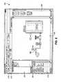
- Fig. 1is a block diagram of a distributed process control network located within a process plant including an operator workstation that implements a display routine which uses smart process objects to create process modules and graphic displays to simulate the operation of the process plant;
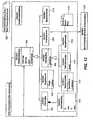
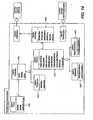
- Fig. 2is a logical block diagram of a set of applications and other entities, including smart process objects and process modules, stored in the operator workstation of Fig. 1 , which may be used to implement enhanced functionality in a process plant;
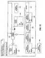
- Fig. 3is a simplified depiction of a configuration screen used by a configuration engineer to create a process graphic display or a process module using smart process objects stored in an object library;
- Fig. 4is a detailed depiction of an exemplary process graphic display including a depiction of streams and connection elements within the process plant, the depiction being created by interconnecting the graphic display elements of a number of smart process obj ects;
- Fig. 5is a logical block diagram of a manner in which process modules using smart process objects may be created in and implemented within an existing process control network;
- Figs. 6-11are depictions of portions of multiple exemplary process graphic displays configured and constructed using a markup language-based object model
- Figs. 12-14are simplified representations of respective portions of an object model framework set forth in a class diagram identifying relationships between classes of the object model framework;
- Fig. 15is a schematic representation of the defining components of an exemplary process graphic display, including a rendering definition set forth in a declarative language;
- Fig. 16is a schematic representation of the defining components of an exemplary composite shape class that may be used in creating and configuring a process graphic display;
- Fig. 17is a schematic representation of a database storage instance diagram that identifies relationships between an exemplary process graphic display utilizing a number of composite shapes having defined parameters;
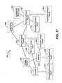
- Fig. 18is a schematic representation of assemblies created in connection with the generation of a runtime process graphic display from the configuration environment components described in connection with Figs. 15 and 16 ;
- Fig. 19is a further schematic representation of assemblies, files and other items created in connection with the generation of a runtime process graphic display.
- Fig. 20is a schematic representation of a data source object model portion of the object model framework for an exemplary data source.
- the process plant user interface system disclosed hereinis generally configured and structured to present user information and content in support of the operation and maintenance of the process plant in a consistent and familiar form, and in an extensible and flexible manner.
- the content and information presented via the user interfaceis created, configured, stored and processed in a manner that enables broad, configurable and customizable access thereto.
- the user interface and its graphic structurese.g., graphic display elements representative of process plant elements, as well as menu, panel, faceplate and other user interface structures
- links to other documents or data sources, and any other embedded or composite shapesare set forth, configured, and defined in a flexible and extensible format.
- the formatmay be defined by a declarative (or markup) language referred to herein as PGXML (Process Graphics Extensible Markup Language).
- PGXMLmay be based on the industry standard markup language XML.
- the comprehensive definition of the user interface via PGXMLmay also support the rendering of advanced graphics.
- the PGXML script to be described hereinmay be convertible into a vector graphics format, such as Microsoft XAML or Scalable Vector Graphics (SVG).
- Non-graphics related components of the PGXML scriptmay then be used to create and establish data structures, commands or other instructions, and files to support the other functionality defined via the PGXML description of the user interface.
- the PGXML scriptgenerally sets forth internal definitions of the graphics structures of the graphic display elements to be depicted in a display, as well as other aspects of the elements, in order to support the generation of process graphics runtime files to be downloaded to the workstations and other display devices on which the display will be depicted.
- a primary purpose of the user interfaceis to provide a virtual view into the process plant at a system level.
- described hereinis a modular, object-oriented approach to defining a user interface that provides the virtual view of the process plant in both on-line and off-line contexts and that enables interaction and control at the system level.
- the graphical objectsmay include properties that specify data sources for process values from the process plant, for process control values from the process control system, and for values and data from other systems or sources, as described below. Such properties, and the files and other data generated therefrom, accordingly establish data communication links for the process graphics rendered from the graphical objects.
- Fig. 1an example process plant 10 in which smart process objects are used to form process graphic displays and process modules, both of which may be integrated with control modules to provide enhanced control and simulation within the plant environment, is illustrated in detail.
- the process plant 10uses a distributed process control system having one or more controllers 12, each connected to one or more field devices 14 and 16 via input/output (I/O) devices or cards 18 which may be, for example, Fieldbus interfaces, Profibus interfaces, HART interfaces, standard 4-20 ma interfaces, etc.
- the controllers 12are also coupled to one or more host or operator workstations 20 and 22 via a data highway 24 which may be, for example, an Ethernet link.
- a database 28may be connected to the data highway 24 and operates as a data historian that collects and stores parameter, status and other data associated with the controllers and field devices within the plant 10 and/or as a configuration database that stores the current configuration of the process control system within the plant 10 as downloaded to and stored within the controllers 12 and field devices 14 and 16. While the controllers 12, I/O cards 18 and field devices 14 and 16 are typically located down within and distributed throughout the sometimes harsh plant environment, the operator workstations 20 and 22 and the database 28 are usually located in control rooms or other less harsh environments easily assessable by controller or maintenance personnel.
- each of the controllers 12which may be by way of example, the DeltaV TM controller sold by Emerson Process Management, stores and executes a controller application that implements a control strategy using any number of different, independently executed, control modules or blocks 29.
- Each of the control modules 29can be made up of what are commonly referred to as function blocks wherein each function block is a part or a subroutine of an overall control routine and operates in conjunction with other function blocks (via communications called links) to implement process control loops within the process plant 10.
- function blockswhich may be objects in an object oriented programming protocol, typically perform one of an input function, such as that associated with a transmitter, a sensor or other process parameter measurement device, a control function, such as that associated with a control routine that performs PID, fuzzy logic, etc. control, or an output function that controls the operation of some device, such as a valve, to perform some physical function within the process plant 10.
- an input functionsuch as that associated with a transmitter, a sensor or other process parameter measurement device
- a control functionsuch as that associated with a control routine that performs PID, fuzzy logic, etc. control
- an output function that controls the operation of some devicesuch as a valve
- MPCsmodel predictive controllers
- optimizersetc.
- the Fieldbus protocol and the DeltaV system protocoluse control modules and function blocks designed and implemented in an object oriented programming protocol
- the control modulescould be designed using any desired control programming scheme including, for example, sequential function block, ladder logic, etc. and are not limited to being designed and implemented using the function block or any other particular programming technique.
- the field devices 14 and 16 connected to the controllers 12may be standard 4-20 ma devices, may be smart field devices, such as HART, Profibus, or FOUNDATION TM Fieldbus field devices, which include a processor and a memory, or may be any other desired type of device. Some of these devices, such as Fieldbus field devices (labeled with reference number 16 in Fig. 1 ), may store and execute modules, or sub-modules, such as function blocks, associated with the control strategy implemented in the controllers 12. Function blocks 30, which are illustrated in Fig. 1 as being disposed in two different ones of the Fieldbus field devices 16, may be executed in conjunction with the execution of the control modules 29 within the controllers 12 to implement process control, as is well known.
- Fieldbus field deviceslabeled with reference number 16 in Fig. 1
- Function blocks 30, which are illustrated in Fig. 1 as being disposed in two different ones of the Fieldbus field devices 16may be executed in conjunction with the execution of the control modules 29 within the controllers 12 to implement process control, as is well known.
- the field devices 14 and 16may be any types of devices, such as sensors, valves, transmitters, positioners, etc.
- the I/O devices 18may be any types of I/O devices conforming to any desired communication or controller protocol such as HART, Fieldbus, Profibus, etc.
- the workstation 20includes a suite of operator interface applications and other data structures 32 which can be accessed by any authorized user (sometimes referred to herein as a configuration engineer and sometimes as an operator although other types of users may exist) to view and provide functionality with respect to devices, units, etc. connected within the process plant 10.
- the suite of operator interface applications 32is stored in a memory 34 of the workstation 20 and each of the applications or entities within the suite of applications 32 is adapted to be executed on a processor 36 associated with the workstation 20. While the entire suite of applications 32 is illustrated as being stored in the workstation 20, some of these applications or other entities could be stored in and executed in other workstations or computer devices within or associated with the plant 10.
- the suite of applicationscan provide display outputs to a display screen 37 associated with the workstation 20 or any other desired display screen or display device, including hand-held devices, laptops, other workstations, printers, etc.
- the applications within the suite of applications 32may be broken up and executed on two or more computers or machines and may be configured to operate in conjunction with one another.
- the suite of applications 32provides for or enables the creation and use of three different types of entities, the operation of which may be integrated together to provide for enhanced control, simulation, and display functions within the process plant 10. More particularly, the suite of applications 32 may be used to create and implement process graphic displays 35 (which generally provide an operator display pertaining to a portion of the process plant), process modules 39 (which generally provide a simulation of a portion of a process plant) and process control modules, such as the control modules 29, which generally provide or perform on-line control of the process.
- the process control modules 29are generally well known in the art and may include any type of control module, such as function block control modules, etc.
- the process graphic display elements 35which are described in more detail below, are generally elements that are used by an operator, engineer or other displays to provide information to a user, such as an operator, about the operation, configuration or set-up of the process plant and the elements therein.
- the process modules 39are generally closely tied to the process graphic display elements 35 and may be used to perform simulations of the operation of the process plant or of some of the different elements therein connected in the manner depicted in the process graphic displays 35.
- the process graphic displays 35 and process modules 39are illustrated as being stored in and executed by the workstations 20 and 22, although the process graphic displays 35 and the process modules 39 could be downloaded to and executed in any other computer associated with the process control plant 10, including laptops, handheld devices, etc.
- Fig. 2illustrates some of the applications and data structures or other entities within the suite of applications 32 of the workstation 20.
- the suite of applications 32includes control module, process module, and graphic display configuration applications 38 which are used by a configuration engineer to create control modules, process modules (also called process flow modules) and the associated graphic displays.
- control module configuration application 38may be any standard or known control module configuration application
- the process module and graphic display configuration application(s)may create process modules and graphic displays using one or more smart process objects, the nature of which are described in more detail below.
- the process module and process graphic configuration applications 38are shown separately, one configuration application could create both of these types of elements.
- a library 40 of smart process objects 42includes example or template smart process objects 42 that may be accessed, copied and used by the configuration application 38 to create process modules 39 and graphic displays 35.
- the configuration application 38may be used to create one or more process modules 39, each of which is made up of or created from one or more smart process objects 42 and may include one or more process flow or simulation algorithms 45, which are stored in a process module memory 46.
- the configuration application 38may be used to create one or more graphic displays 35, each of which is made up of or created from one or more smart process objects 42 and may include any number of display elements connected together.
- One of the graphic displays 35bis illustrated in Fig. 2 in expanded form and includes a depiction of a set of process elements, such as valves, tanks, sensors and flow transmitters, interconnected by connection elements which may be pipes, conduit, power cables, conveyors, etc.
- An execution engine 48operates or implements each of the graphic displays 35 and the process modules 39 during runtime to create one or more process displays for an operator as defined by the graphic displays 35 and to implement simulation functionality associated with the process modules 39.
- the execution engine 48may use a rules database 50 defining the logic to be implemented on the process modules 39 as a whole and the smart process objects within those modules in particular.
- the execution engine 48may also use a connection matrix 52 which defines the connections between the process elements within the plant 10 as well as within the process modules 39 to implement the functionality for the process modules 39.
- Fig. 2illustrates one of the smart process objects 42e in more detail. While the smart process object 42e is illustrated as being one of the template smart process objects, it will be understood that other smart process objects will generally include the same or similar elements, features, parameters, etc. as described with respect to the smart process object 42e and that the specifics or values of these elements, features and parameters may be changed or varied from smart process object to smart process object depending on the nature and use of that smart process object. Furthermore, while the smart process object 42e may be an object within an object oriented programming environment and thus include data stores, inputs and outputs and methods associated therewith, this smart process object may be created by and implemented within any other desired programming paradigm or protocol.
- the smart process object 42ebefore being instantiated, is an object that is associated with a particular type of entity, such as a physical or a logical entity, within the process plant 10 of Fig. 1 . However, after being copied and instantiated, the smart process object 42e may be tied to a particular entity within the process plant.
- the smart process object 42eincludes a data store 53 that is used to store data received from or pertaining to the logical entity with which the smart process object 42e is associated.
- the data store 53generally includes a data store 53a that stores general or permanent information about the entity to which the smart process object 42e pertains, like manufacturer, revision, name, type, etc.
- a data store 53bmay store variable or changing data, such as parameter data, status data, input and output data, cost or other data about the entity to which the smart process object 42e pertains including data associated with the entity as it has existed in the past or as it now exists within the process plant 10.
- the smart process object 42emay be configured or programmed to receive this data (e.g., cost data) on a periodic or non-periodic basis, from the entity itself via any desired communication link, from the historian 28 via the Ethernet bus 24 or in any other desired manner.
- a data store 53cmay store a graphical representation of the entity to which the smart process object 42e pertains and which is used for actual display to the operator via an operator interface, such as the screen 37 associated with the workstation 20 of Fig. 1 .
- the graphical representationmay include place holders (marked by underlines within the data store 53c) for information about the entity, such as information defined by the parameter or other variable data about the entity as stored in the data store 53b.
- This parameter datamay be displayed in the graphical place holders when the graphical representation is presented to the operator on a display device 37 as part of one of the graphic displays 35.
- the graphical representation (and the smart process object 42e)may also include predefined connection points (marked by an "X" in the data store 53c) that enable an operator or configuration engineer to attach upstream or downstream components to the process element, as depicted by the graphical representation.
- connection pointsalso enable the smart process object 42e to be aware of the elements connected to that smart object as configured within a process module and may specify a type of connection element that must be used, such as a pipe, a duct, etc., a stream associated with that element, etc.
- the smart process object 42emay also include one or more inputs 54 and outputs 56 to enable communication with other smart process objects within or outside of a process module in which the smart process object 42 is used.
- the connections of the inputs 54 and outputs 56 to other smart process objectsmay be configured by a configuration engineer during configuration of a process module by simply connecting other smart process objects to these inputs and outputs or by specifying particular communications that are to take place between smart process objects. Some of these inputs and outputs may be defined as being connected to the smart process objects connected at the predefined connection points for the smart process object as discussed above.
- These inputs 54 and outputs 56may also be determined or defined by a set of rules within the rule database 50 and the connection matrix 52 defining the connections between different devices or entities within the plant 10.
- the inputs 54 and the outputs 56which include data stores or buffers associated therewith will, generally speaking, be used to provide communications of data from other smart process objects to the smart process object 42e or to provide communications of data stored within or generated by the smart process object 42e to other smart process objects. These inputs and outputs may also be used to provide communications between the smart process object 42e and other objects within the process control system, such as control modules within the controllers 12, field devices 14,16, etc.
- the smart process object 42ealso includes a method storage 58 that is used to store zero, one or more methods 60 (illustrated as methods 60a, 60b and 60c in Fig. 2 ) which may be algorithms to be implemented by the smart process object 42e during execution of a process module in which the smart process object 42e is used.
- the methods 60 stored in the method storage 58will use the data stored within the data storage portions 53 a and 53b and data obtained from other smart process objects or even data from other sources, such as the configuration database or historian 28, via the inputs 54 and the outputs 56 to determine information about the process plant 10 or an entity within the plant 10.
- the methods 60may determine poor or bad operating conditions associated with the entity defined by the smart process object 42e, errors associated with that or other entities within the process plant 10, etc.
- the methods 60may be preconfigured or provided based on the type or class of smart process object and will generally be executed each time the smart process object 42e is executed within the execution engine 48 during runtime.
- Some example methods 60 that may be provided within a smart process object, such as the smart process object 42e,include detecting leaks, dead band, dead time, movement, variability, condition monitoring, computing costs, or other conditions associated with the entity.
- the methods 60may also be provided to help simulate the operation of the process entity associated with the smart process object on the material flowing through that process entity.
- the methods 60may be provided to calculate mass balances, energy balances, flows, temperatures, compositions, vapor states, and other system-level or stream level parameters associated with the material in the plant 10, to simulate operation of the element so as to calculate expected outputs based on provided inputs, etc.
- theseare but a few of the methods that can be stored in and run by a smart process object 42e, and there are many other methods that may be used, with such methods generally being determined by the type of entity being represented, the manner in which that entity is connected in and used in a process plant as well as other factors.
- the smart process object 42emay store and execute methods that detect system-level conditions, errors, etc., these methods may also be used to determine other information about devices, logical elements, such as process control modules and loops, and other non-system-level entities.
- the methods 60may be programmed or provided in any desired programming language, such as C, C++, C#, etc. or may be referenced to or may define applicable rules within the rule database 50 that should be run for the smart process object 42e during execution.
- each smart process objectmay include a library of applicable algorithms or methods which may be used to define the simulation behavior of the smart process object when connected within a process module.
- a libraryis illustrated in a pull down menu 61 for the smart process object 42e of Fig. 2 and a similar menu may be associated with each other smart process object.
- the configuration engineermay define the simulation behavior of a smart process object when this smart process object is placed in a process module 39 by selecting one of the library of simulation algorithms (called method 1, method 2, etc.) via, for example, the pull down menu 61. In this manner, the configuration engineer may define different simulation behaviors for a smart process object depending on the type or nature of the process for which the smart process object is being used to model.
- the configuration engineermay instead provide a proprietary or other user supplied algorithm to define the simulation behavior of the process element defined by the smart process block.
- a user defined algorithmillustrated as the "user defined” entry in the pull down menu 61
- This functionalityenables the simulation behavior to be customized by the user to thereby provide for better or more accurate simulation.
- the smart process objects 42 or each process module 39may include an operator actuatable switch (such as an electronic switch or a flag) that disables the use of the simulation algorithms within the smart process objects and that, instead, causes the behavior of the process module to be determined by a high fidelity simulation package or program, such as one provided by HYSYS.
- an operator actuatable switchsuch as an electronic switch or a flag
- the smart process object or the process moduleobtains simulated parameters from the high fidelity simulation, as opposed to using the simulation algorithms within the smart process objects themselves.
- the engine 48During execution of a graphic display 35 or a process module 39 by the execution engine 48, the engine 48 implements the communications defined by the inputs 54 and outputs 56 to each of the smart process objects in the graphic display 35 or process module 39 and may implement the methods 60 for each of those objects to perform the functionality provided by the methods 60.
- the functionality of the methods 60may be located in programming within the smart process object or defined by a set of rules within the rule database 50 that the engine 48 executes, based on the type, class, identification, tag name, etc. of a smart process object, to implement the functionality defined by those rules.
- an instance of the smart process object 42ehas a tag or unique name within the context of the process module with which the smart process object 42e is associated and this tag or unique name may be used to provide communications to and from the smart process object 42e and may be referenced by the execution engine 48 during runtime.
- Process module tagsshould be unique within the control system configuration. This tagging convention enables elements within the process modules 39 to be referenced by elements within others of the process graphic displays 35, process modules 39 and even the control modules 29.
- the parameters of the smart process object 42ecan be simple parameters, such as simple values, structured parameters or smart parameters that know the expected units and attributes associated therewith.
- Smart parameterscan be interpreted and used by the process rules engine or execution engine 48 to assure all signals are being sent in the same units or are converted properly. Smart rules can also be used to turn on and turn off groups of alarms for the smart process objects (or process modules) to create a smart alarm strategy and/or interface for the operator. Still further, smart process object classes can be associated with equipment and module classes within the process control strategy of the plant 10 to provide a known linkage between a smart process object and the process variables it will need to interpret or access.
- Smart process objectswhen used in process graphic displays or process modules, may also include mode of operation, status, and alarm behavior so that these smart objects may be put in different modes during runtime, such as the off, start-up, and normal modes, may provide a status associated with the object based on its current operating state, and may provide alarms based on detected conditions, such as a parameter out of range, limited, high variability, etc. Furthermore, the status may be reflected in the smart process object's connection and relied upon, or used, to animate the view of the graphic display element rendered for the object. Status may also be back calculated through smart process objects to affect a state of smart process objects that occurred earlier in the process or displays.
- smart process objectsmay also have a class/subclass hierarchy which enables them to be categorized in class libraries, to be collected together in a composite structure, etc. Still further, smart process objects may utilize information from other elements, such as control modules and other objects to enable the smart process object to recognize when its associated entity is busy or, for example, acquired by a batch control process within the plant 10.
- Smart process objectsmay be associated with any desired process entity, such as physical devices like pumps, tanks, valves, etc., or logical entities such as process areas, measurements or actuators, control strategies, etc.
- smart process objectsmay be associated with connectors, such a piping, conduit, wiring, conveyors, or any other device or entity that moves material, electricity, gas, etc. from one point to another point within the process.
- Smart process objects that are associated with connectorssometimes referred to herein as smart links or connector elements, are also tagged (even though the actual device or connector itself may not be tagged or able to communicate within the process plant 10), and are generally used to represent material flow between other elements in the process.
- Smart linkswill typically include properties or parameters that define how different materials or phenomena (such as electricity) flow through the connection (e.g. steam, electricity, water, sewage, etc.) These parameters may indicate the type and nature of flow (such as the general speed, friction coefficients, type of flow like turbulent or non-turbulent, electromagnetic, etc.) through the connector and the possible direction or directions of flow through the connector.
- Smart linksmay include programming or methods that ensure that the units of the source and destination object to which the smart link connects, match and, if not, may perform a conversion. The methods of the smart link may also model the flow through the connector using a model or an algorithm to estimate the speed or nature of the flow through the actual connectors, length and size of the physical connections, transport delay, etc.
- the stored parameters for the smart process objectmay be used in these methods.
- the smart links or connector elementsenable smart process objects to be aware of the other upstream and downstream objects or entities.
- smart linksmay, for example, define the connections between other objects, the type of fluid, such as liquid, gas, electricity, etc. within the system, the upstream and downstream side of the entities, which other entities are upstream and downstream of the entity for this smart process object, the direction of material, fluid, electric flow, etc. in any desired or convenient manner.
- the matrix 52may be created prior to execution of process flow modules and may define for the smart links the interconnections between the different devices within the plant and, therefore, the interconnections between the different smart process objects.
- the execution engine 48may use the matrix 52 to ascertain the upstream and downstream entities and thereby define the communications between the smart process objects and the methods associated with the smart process objects. Still further, one or more sets of rules may be provided to be used by the smart process objects to interact with each other and to obtain data from each other as needed for the methods within the smart process objects and to resolve the impact of smart objects associated with output connections.
- the smart process object 42emay also include hot links, such as URLs, to key documentation which may be applicable to the type of object, or which may be specific to the instance (depending on the criticality and application) of the device to which the smart process object 42e pertains.
- the documentationmay be vendor supplied as well as user-specific. Some examples of documentation include configuration, start-up and shut-down procedures, operational and maintenance documentation.
- an operatormay click on the object as displayed in an operator display to bring up the instance specific (if any) and generic documentation for the object or associated device. Also, the operator may be able to add/delete/change documentation independently of the system software such as maintenance requests, records of operational problems, etc.
- hot linksmay be user configurable or changeable to provide the ability to add knowledge links to objects in the an operator interface, to provide for quick navigation to appropriate information associated with the object and to provide the ability to add work instructions specific to the customer, to the specific object type or even to the specific instance of the object.
- process modules and process graphicsare described above as being created together by the interconnection of different smart process objects, they may be created separately.
- a process graphicmay be created using smart process objects and, when completed, a process module for that graphic may be generated based on graphic elements and their interconnections in the graphic display.
- the process modulemay be first created using smart process objects and, once created, a graphic display for that process module may be automatically generated by the configuration application 38 using the graphic display elements in the smart process objects used to create the process module.
- a process module and a graphic displaymay be created separately and the individual elements within these two entities may be tied together manually by referencing one another (e.g., using the tag properties of the elements within the graphic display and the process module).
- a smart process objectmay be referenced by multiple displays.
- a process graphic display and an associated process modulemay be run independently or separately, although they will typically communicate parameters and information back and forth as desired or needed.
- a set of predefined graphic elementsmay be provided in the configuration application to enable a user to construct operator or graphic displays that reflect the process plant. These graphic elements are designed to dynamically show on-line measurements and actuators that interface with the control system. In addition, unmeasured parameters that reflect process operation may be calculated using on-line process simulation provided in the process modules and may be shown as an integral part of the associated graphic displays.
- the process simulation provided by the process modulesmay be used in place of the process measurement values in the graphic elements and in the associated control modules. These values, which are calculated by the associated process modules, may be based on the actuator position or state as well as manual disturbance values illustrated in the process graphics.
- the process graphic displays and control modulesmay be used in both on-line or control situation and in off-line or simulation situations.
- the static portion of the graphic elementswill, in many cases, appear similar to the three dimensional components included in known graphics libraries, further unique features or properties of these graphic elements, the information displayed with these elements, and their links to the control system I/O and process simulation modules is described below with respect to a number of possible types and examples of graphic elements.
- Stream elementsgenerally define a stream of material in the process plant and may be exposed in the graphic display to show the composition, density, flow, temperature, pressure, weight, and/or any other parameters defining the stream of material.
- Stream elementsmay be defined at the input of the process module and provided to elements within the process module to thereby enable the flow of material through the process module to be modeled and depicted in the graphic display.
- stream elementsmay be illustrated at the output or end of the process module to illustrate in the graphic display the material output of the portion of the process plant depicted by the graphic display.
- Stream elementsalso may be used to define how different graphic displays (and the associated process modules) are connected with one another.
- the output stream in one process modulemay be the input stream in another process module and may supply the values used at the input stream of the other process module.
- Streamsmay contain the following four parts: name (e.g., pH stream), direction (e.g., flow input), measurement (e.g., flow, pressure, temperature), and composition (e.g., nitrogen, ammonia, etc.) However, streams could have other parts or parameters if so desired.
- Process connection elementsdefine the manner in which materials within the plant, such as solid materials, liquid and vapor, and gases are delivered or carried from one device to another.
- three different types of process connectionsincluding piping, ducts and conveyors may be used.
- other connection elementssuch as electrical cables to address power flow in electro-chemical processes, etc. may be used as well.
- Pipingis generally used to illustrate (and simulate) liquid and high pressure vapor or gas flow within the plant.
- Ductsare generally used to illustrate (and simulate) low pressure gas flow within the plant.
- Conveyorsare generally used to illustrate (and simulate) the movement of solid material between processing units.
- each process connection elementdefines the type of connection, such as a pipe connection, a duct connection or a conveyor connection that is used to provide material at the input or output of a device.
- connection elementmay start at a processing element output, an actuator element output or a stream element output. In a similar manner, a connection element may terminate at a processing element input, an actuator element input or a stream input.
- connection elementmay be automatically displayed when the cursor is placed over the connection element in the graphic display. Also, the properties associated with a connection element may be exposed for permanent display by placing a measurement or estimated property element (defined below) on the connection element. If desired, a connection element may be created by holding the left mouse button down over an element output (such as a stream output, a processing element output or an actuator element output) and, while holding down a button on the mouse, positioning the cursor over an element input. For the connection to be established successfully, the input and the output types (pipe, duct, or conveyor) of the upstream and the downstream elements must match. The connection will automatically take on the type of the upstream element.
- element outputsuch as a stream output, a processing element output or an actuator element output
- piping elementscan be shown or depicted in the process graphic display as a pipe connection
- duct elementse.g., air or gas
- conveyor elementsmay be shown as conveyor belts.
- Piping, duct and conveyor element connectionscan be automatically routed between processing elements and arrows may be displayed outside the depiction of these elements to show the direction of the flow.
- a "T" elementmay be included in the pipe, duct or conveyor.
- "T" elementsmay be used to combine multiple outputs.
- the color or other graphic property of a conveyor elementmay change to indicate its status, e.g., running/stopped, flowing/not flowing, plugged, etc.
- the material flow along a conveyoris determined by the motor drive connected to the conveyor.
- a motor drive actuatorwhich is an actuator element described in more detail below
- measurement elementscan be connected to pipe, duct and conveyor elements to make it possible to expose measurements associated with the pipe, duct or conveyor elements, such as the speed of the conveyor or the flow of material in a pipe or duct, the properties of the material on or in the conveyor, pipe or duct, e.g. moisture or weight.
- an exposed property elementmay be added to display properties of the material on or in the pipe, duct or conveyor that are not measured, for example, the composition of the material.
- each of the piping, duct and conveyor connection elementsmay graphically and dynamically reflect a lost connection (e.g., by a color change), and that a selected property (pressure, temperature, length, etc.) is outside configured limits (e.g., by a color change).
- parameters calculated by the associated process modulemay be exposed in the graphic. For example, properties provided by the upstream connection, whether the connection status is bad or good, limits on one or more selected parameters of the connection element, etc. may be exposed in the graphic display to provide information to the operator about the connection element or the stream being transferred by the connection element.
- actuator elementsare elements that perform some actuation function with respect to the stream and may be placed between different connection elements or between a processing element and a connection element.
- actuator elementsinclude a regulating valve (with actuator), an on-off valve (with actuator), a pump (with motor), a force draft fan (with motor), an induced draft fan (with motor), an eductor (with on-off valve), a damper (with drive), a feeder (with variable speed motor), a conveyor motor drive (which may be attached to a conveyor element), etc.
- the graphic depiction of the valve elementsmay dynamically reflect the implied valve position (by animation, for example), valve failure (by a color change, for example), the valve full open/closed position (by a color change, for example), and the AO, DO, DC, setpoint, PV, OUT, mode, etc. (by a numeric string or other indication, for example) of the associated control block controlling that valve.
- the simulation element associated with the valve elements(used in the process module) may have simulation algorithms that calculate parameters associated with the valve actuator, such as the discharge pressure, mass flow, liquid temperature, liquid composition, inlet pressure, and outlet pressure. These simulated or calculated parameters may be exposed in the process graphic, if so desired.
- the user or configuration engineermust usually configure the reference to an AO, DO or DC block in a control module associated with the valve as well as the valve type (e.g., linear, quick opening, equal percentage, valve sizing, etc.) and the stroke time from open to close.
- the simulation algorithms available to simulate the operation of the valve on the material flowing through the valvemay be dependent upon the type of the valve and sizing information.
- the graphic depiction of pump elementsmay dynamically reflect the motor status (using, for example, a color change), the associated DO or DC function block mode and setpoint (using, for example, strings), the motor speed (if variable speed drive is used), the AO setpoint, PV, OUT mode (if variable speed drive is used) and other desired parameters.
- the process simulationused in the process module
- the process simulationmay determine or calculate parameters such as the discharge pressure, liquid composition, liquid temperature, and mass flow, which parameters may be exposed in the graphic display. The user may need to define a pump curve based on the pump type.
- the usermay configure the reference to the DO or DC block associated with the motor start/stop, the reference to the associated AO function block for variable speed drive (if used), and the pump curve (e.g., pressure versus flow) for the defining the operation of the pump.
- the reference to the DO or DC block associated with the motor start/stopthe reference to the associated AO function block for variable speed drive (if used)
- the pump curvee.g., pressure versus flow
- the graphic depiction of a force draft or an induced fan actuator elementmay have a depiction that dynamically reflects the motor status, DO or DC function block mode and setpoint, motor speed (if variable speed drive is used), the AO setpoint, PV, OUT, DO or DC function block mode (if variable speed drive is used) and other desired parameters, any of which may be exposed in the graphic display.
- the process simulation element(used in a process module) for this element may determine or calculate parameters such as the discharge pressure, gas composition, gas temperature, and gas mass flow, which parameters may be exposed in the graphic display.
- the usermay configure the reference to the associated DC block for motor start/stop, the reference to an AO block for variable speed drive (if used), and the fan curve (pressure versus flow) for defining the simulated operation of the fan.
- a particular type of actuatormay only be used with a specific type of connection, e.g., a pipe, a duct or a conveyor.
- the table belowdefines some example connection limitations for typical actuator elements. Pipe Duct Conveyor Regulating valve X On-Off Valve X Pump X Eductor X Force Draft Fan X Induced Draft Fan X Damper Drive X Feeder X X Motor Drive X
- Processing elementsinclude plant equipment that processes the materials or streams in the plant in some manner. Generally speaking, all inputs and outputs to and from processing elements will be made through connection elements. Standard processing elements include tanks (vertical and horizontal), heaters, static mixers, reactors, mixers, air heaters and any other elements that perform some type of simple or standard processing activity. For standard processing elements, the user may specify the number of inputs and outputs to the element along with the physical equipment properties e.g. size, volume, etc. The simulation algorithm and static representation of these standard processing elements may be set so that they cannot be modified by the user but may be selectable as described above at configuration time.
- custom processing elementsmay be implemented as custom processing elements.
- the static representation, number of inputs and outputs and the simulation algorithm of such custom processing elementsmay be modified to meet the user interface requirements.
- the tank standard processing elementmay be configured based on the pipe connections to the tank and the tank element may dynamically reflect the level in the tank (using, e.g., dynamic animation), and the level at 100% or empty (using a color change, for example).
- the process module simulation for the tankmay calculate and expose, via the graphic display, parameters such as the outlet temperature, the outlet composition, the liquid temperature and the simulated level of the tank.
- the user or configuration engineermay need to configure the number of input and output connections, the complete connections to the tank, the tank properties, such as size (e.g., diameter and height), etc.
- the heater processing elementmay dynamically calculate and reflect, via the graphic display, the heat transfer coefficient (e.g., using a color change), the outlet product temperature, the inlet product temperature, the outlet pressure (assuming fixed drop), etc.
- the heat transfer coefficiente.g., using a color change
- the outlet product temperaturee.g., the inlet product temperature
- the outlet pressureassuming fixed drop
- a user or configuration engineermay need to configure the complete connections to the heater, the heater surface area and the heat transfer coefficient when clean.
- Non-standard processing elementssuch as distillation columns, evaporators, separators, boilers, etc. may be represented graphically using a custom processing element in which the simulation associated with the vessel may be user defined if not included in a standard selection.
- the processing in these elementsmay be described or defined as a step response model relating each input to each output of the vessel. Inputs may be gas and/or liquid streams.
- the usermay define the equations that describe the relationships between the inputs and outputs of the processing element and these equations may be stored in the process module using that element to perform simulation.
- some simple static graph representationsmay be provided to help the user quickly create the static graphics associated with a custom processing element. If these simple graphics are used, then the user may need to only specify the desired number of input and output connections and the type of connection supported (e.g., pipe, duct, or conveyor) supported by the custom processing element. In response, the graphic item will be displayed and can be immediately used in the creation of the operator graphic. If desired, the gains and any dynamics associated with each input and output of the process element may be specified if the user elects to specify the simulation algorithm as step responses. If the user selects a custom algorithm, then an expression editor may be provided for the user to define the simulation algorithm. Based on the method selected, the properties of the custom processing element outputs may be calculated differently. Furthermore, the user may reference one or more of the algorithms that they have defined in a separate software assembly.
- the usermay reference one or more of the algorithms that they have defined in a separate software assembly.
- pre-defined composites or templatesmay be provided for creating custom processing elements.
- These templatesmay include, for example, a boiler template having a custom algorithm that calculates the exit gas O 2 , the exit gas CO, the steam generated, the boiler drum level and the boiler draft.
- a templatemay be based on a single fuel input. However, by modifying the template, it is possible to simulate boilers with multiple fuels.
- Other pre-defined templatesmay include a specialized vessel-cyclone separator template, which may be used with in conjunction with a spray dryer custom processing element, and which may include a step response model to model the operation of the separator.
- a column template, a spray dryer, and an evaporator bodymay utilize a step response model to define the expected process response.
- the concentration of the outlet flow and vapor releasecan be calculated.
- Multiple evaporator elementsmay be connected together along with heat exchanger and eductor elements to create a multiple-effect evaporator.
- a specialized vessel-stack custom template processing elementmay be used with the boiler processing element.
- the properties of the inletmay be carried through the stack with no modifications if so desired, or to reflect emissions reductions performed in the stack.
- Measurement elementsinclude transmitter elements, which may be used in the graphic display to access the measurement value associated with a physical transmitter, and switch elements. Generally, the transmitter element may dynamically reflect bad or uncertain status, the mode of the associated AI function block in the control module, the measurement value and units, etc. associated with an actual transmitter (sensor) or other data associated with the actual transmitter. In an off-line mode (or simulation mode) the transmitter element may be used to access and display the simulation value provided by the process module rather than the value associated with the AI or PCI block or may be used to provide a measurement value to the associated AI block in the control module as a measurement to be used in the simulated control routine.
- the transmitter elementcan be added to a connection element or to a processing element and, when such a transmitter element is added to the display, the user will generally need to identify the associated AI, PCI or DI block in controller scheme that is providing the measurement.
- the on-line modethe value of the measurement may be shown next to this measurement element.
- the off-line modeor simulation mode
- the simulated value of the measurement(as developed by the corresponding process module) may be automatically displayed.
- the usercan elect to switch control and display to the simulated value in the event of a measurement failure.
- a switch elementmay dynamically reflect a bad or uncertain status, the mode of the associated DI (e.g., manual or OS), and the discrete value of a switch (on, off, etc.)
- the usermay use the switch display element to access and change the switch parameters in the graphic display and control module by selecting a simulation value or a manual value and status and by manually entering the value and status of the switch.
- a usermay generally configure the switch element by providing a reference to an associated DI block in the control scheme, a reference to the element property that triggers the switch, and the limit and deadband associated with a change of state of the switch.
- An estimated property elementgenerally exposes an estimated property of the system as determined by the process module and may be added to a connection or processing element to display any property of that element. When this element is placed on a connection element or on a piece of equipment, the user can browse and select the properties that will be displayed. Thus, simulated properties that are not available through a physical measurement may be exposed through the use of the estimated properties element.
- Such an estimated property elementmay dynamically reflect a good/bad connection, the estimated property value(s), and a property that is outside of an associated limit or change. A user must generally configure the reference to property(s) to be displayed and the limits and color changes for the element if the property is outside of the limits.
- transmitter elements and estimated property elementsmay be referenced during on-line operation or off-line simulation. These properties may also be made visible in the process graphic display.
- a configuration display 64includes a library or template section 65 and a configuration section 66.
- the template section 65includes a depiction of sets of template smart process objects 67, which may include the smart process objects 42 of Fig. 2 and may be any of the connection, measurement, stream, processing, and estimated property elements described above. If desired, non-smart elements 68 that only have a graphic definition may also be provided.
- the templates 67 and 68are generic objects that may be dragged and dropped onto the configuration section 66 to create an instance of a smart process object within a process module or graphic display (or both).
- a partially completed process graphic display 35cis illustrated as including a valve, two tanks, two pumps, a flow transmitter and two sensors interconnected by flow path connectors, which may be smart links or connector elements as described above and providing a stream output. It will be noted that the graphic display 35c may be made up of both smart process objects and non-smart elements.
- the configuration engineermay select and drag the smart process objects 67 and the elements 68 illustrated in the template section 65 onto the configuration section 66 and drop them there in any desired location.
- the configuration engineerwill select and drag one or more smart device process objects 67a or non-smart elements 68 depicting devices onto the configuration section 66.
- the configuration engineerwill then interconnect the smart device process objects within the configuration section 66 with smart connector process objects 67b and may place input and output streams 67c into the display.
- non-smart elementsmay be added to the display.
- the configuration engineermay change the properties of each of the smart process objects during this process using pop-up properties menus, etc.
- the configuration engineermay define rules or other functionality associated with the module.
- rulesmay be execution rules such as those associated with the performance of system-level methods, like mass balance and flow calculations.
- the process engineer or operatormay also decide to add trends and faceplates that would be useful when the process display is on-line.
- the configuration engineermay save that display in a memory and may, at that time, or later, instantiate and download that display to the execution engine 48 in a manner that the execution engine 48 may provide a graphic display.
- the configuration engineercould create a process module in the same or similar manner although different graphics may be depicted for process module elements as opposed to process graphic display elements.
- the operatormay elect to turn on levels of detail while they are running the plant. For example, one of the levels of detail would show the composition at each connection.
- the process graphic or process modulemay be provided with a specific tag.
- smart process object elements within a graphics display or a process modulemay be provided a tag including an alias that can be filled in or selected at runtime by, for example, the execution engine 48 based on other factors, such as a piece of equipment or a route selected within the process control system.
- alias names and indirect referencing in process control systemsis discussed in detail in U.S. Patent No. 6,385,496 , which is assigned to the assignee of the present invention and which is hereby expressly incorporated by reference herein. Any of these techniques may be used to provide and resolve aliases in tags for the smart process objects described herein. With the use of aliases and the like, the same process module may include or be used to support different views for sets of equipment, etc.
- the configuration application 38may be used to design the display 64 of Fig. 3 in a multi-layered manner such that, for example, tabs (View 1, View 2 and View 3) may be used to access and create different views of the process module or graphic display. These tabs may be used in this configuration environment to access and create the different views, and may, or may not, be made available for switching between such views during runtime (i.e., when the execution engine 48 generates the process graphic display for a user). In either case, the different views may be selectively provided to support different users associated with the process plant.
- the configuration application 38automatically stores the smart process objects, along with the connections therebetween, in a database.
- This databasemay then be used to create other process modules and graphic displays using one or more of the same smart process objects.
- the configuration engineercan simply reference the smart process object, as already created and stored within the database, and any methods, etc. stored therewith to place that smart process object in the further display.
- the databasemay be populated as the process control modules and graphic displays are created and the database may be used at any time to create and execute other displays and modules using smart process objects which already exist within the process flow database.
- each smart process object within the databasemay support or be used in process modules and referenced in multiple graphic displays.
- the process modulesmay be constructed by building displays for these modules and then specifying flow algorithms to be used in or associated with process modules.
- individual process modulesmay be spread across and executed by different computers and process modules may be communicatively connected to one other to operate in conjunction with each other, either on the same or on different computers. When this is done, input and output streams will be externally referenced to tie process modules together.
- the configuration engineermay, as part of the process module or graphic display creation, attach or provide the simulation algorithm of the process module.
- These simulation algorithmsmay be preconfigured to calculate or determine certain process or system-level properties, such as mass balance calculations, flow calculations, efficiency calculations, economic calculations, etc. with respect to the process depicted or modeled by the process module.
- the process modulesthemselves may have mode, status, and alarm behavior, can be assigned to workstations, and may be downloaded as part of the display downloads.
- the simulation algorithmsmay be executed by the execution engine 48 to perform mass or heat balancing, flow routing, flow efficiency, flow optimization, economic calculations related to process simulation or other desired calculations using the data provided in the smart process objects of the process module.
- these simulation algorithmsmay access parameters from the control strategy, i.e., the control modules associated with and downloaded to the controllers, field devices, etc. and may, conversely, provide data or information to these control modules.
- the execution engine 48is needed to enable the process algorithms to execute across an amalgamation of all process objects and links configured on all displays.
- the simulation algorithms(within the process modules) will generally execute regardless of whether any associated graphic display is loaded, i.e., called up and currently displaying information to a user.
- the simulation algorithmsmay be cross-checked across the entire process 10 or across defined subsets of the process 10.
- the execution engine 48may provide a display to an operator on an operator interface depicting the interconnected objects or entities within the process module based on the graphic display associated with that process module. The parameters, graphics, etc. of the display will be determined by the configuration and interconnection of the smart elements within the process module.
- alarms and other information to be provided on this or other displaysmay be defined and generated by the methods within the smart process objects and the simulation algorithms associated with a particular process module.
- the execution engine 48may provide a display for a process module to more than one operator interface or may be configured or set to provide no display, even though the execution engine 48 continues to execute the process flow module and thereby perform the methods, alarm behavior, flow algorithms, etc. associated therewith.
- Fig. 4illustrates an exemplary process graphic display 100 that may be created using the elements and configuration applications described above.
- the graphic display 100depicts a portion of process plant that produces white vinegar from water, acid and a base.
- the process graphic display 100includes four stream elements 102 at inputs thereto defining the streams of Base Feed, Acid Feed, Water Feed and cooling water.
- the Base Feed stream 102is delivered through a piping connection element 104 to an actuator element in the form of a valve 106.
- the output of the valve 106is connected to a first input of a mixer 108 via a piping connection element 104.
- the Acid Feed 102is connected to a transmitter element 110 and then to a further valve 112 which is connected to the mixer 108.
- the Acid Feed 102 and transmitter 110, the transmitter 110 and the valve 112 and the valve 112 and the mixer 108are connected via piping connection elements 114.
- an output of the mixer 108is connected to a heat exchanger 122 via piping and two transmitters 124 and 126.
- the cooling water stream 102is delivered to the heat exchanger 122 via a valve 128 and exits the heat exchanger via a valve 130 to produce a return water stream element 131.
- the output of the heat exchanger 122is delivered through a transmitter element 132 and a valve 134 to provide an output Acetic Acid stream element 136. While not always called out in particular, the elements in the graphic display are in all cases connected with one another via piping connection elements.
- display boxes 140which may be generated as properties of the display elements themselves or which may be separate elements in the form of transmitter and estimated property elements or element that reference blocks in control modules, are illustrated in the graphic display 100 to indicate or expose parameters, such as process variable (PV) values, setpoint (SP) values, OUT values, etc. associated with the different elements. Additionally, if the user were to place a cursor over some of the elements, the display 100 may illustrate other values associated with the referenced elements. For example, placing the cursor over one of the stream elements (such as the Acetic Acid stream output 136), may cause the graphic to indicate the composition, pressure, temperature, density, flow rate, etc. of the acid stream at this point in the process.
- the stream elementssuch as the Acetic Acid stream output 136
- the values and parameters displayed on the graphic display 100may be delivered from an actual referenced transmitter within the process control system (such as from an AI block in the control system), or from a process module simulation element that simulates the functionality of the element.
- the graphic display 100 of Fig. 4may be provided to a user during operation of the process which makes white vinegar or to implement a simulation of that process to be used, for example, to perform design or operator training activities.
- the functionality of the smart process objects, the graphic display elements and the process modules described hereinmay operate in the operator workstation 20 and does not need to be downloaded to and configured within the controllers, field devices, etc. within the plant 10, which makes this functionality easier to implement, view, change, etc. Further, this functionality enables system level determinations to be made more easily than within the process devices, controllers, etc. because the information pertaining to the devices on a system level is all typically available to the operator workstation 20 in general and to the execution engine 48 in particular whereas all of this information is not typically made available to each controller and field device within the process plant 10.
- some of the logic associated with the process modulesmay be embedded in the devices, equipment and controllers down within the process plant.
- the use of smart process objects to create integrated process control modules and graphic displaysenables the execution engine 48 to, for example, automatically detect leaks and produce smart alarms with minimal amounts of user configuration activities, to calculate and track flow and mass balances within the plant 10, to track losses within the plant 10 and to provide higher level diagnostics for the plant 10 and to simulate the operation of the plant during engineering design and operator training.
- Fig. 5depicts one possible manner of integrating the execution engine 48 and the process modules and graphic displays used thereby within a process plant having a distributed control strategy.
- Process algorithms 224may be connected to these display class definitions prior to runtime and then the display class definitions and flow algorithms bound thereto may be instantiated and provided to the graphic display/ process module runtime environment 226 (which may be implemented in the form of one or more execution engines 48 in one or more workstations).
- the graphic display/process module runtime environment 226uses a download script parser 228 to parse the code during execution (i.e., to perform just in time object code conversion) and uses a ruled-based execution engine 230 to execute flow algorithms or other rule based procedures provided for or bound to the display classes. During this process, the graphic display/process module runtime environment 226 may communicate with the control module runtime environment 232, which may be executed in controllers and field devices associated with the process, to provide data or information to the control module runtime environment 232 or to access data or other information from the control module runtime environment 232.
- the graphic display/process module runtime environment 226may communicate with the control module runtime environment 232 using any desired or preconfigured communication networks, such as the Ethernet bus 24 of Fig. 1 . Still further, other methods of integrating the graphic displays, process modules and control modules described herein into a standard process control system or process plant may be used as well.
- each smart process objectrepresents a physical device or process plant element.
- each smart process objectdefines a graphic display element that may be used in a process graphic display depicting that element.
- Each smart process objectmay also define or establish a simulation model of the process plant element, which may include one or more algorithms, methods, or other actions directed to providing an off-line simulation of the process plant element.
- a smart process objectmay include a rendering definition of a graphic display element to be displayed to the operator, data storage for storing parameters pertaining to the location (e.g., path) and processing of data indicative of the on-line operation of the process plant element, and methods, algorithms, or other steps that may be implemented as a result of events occurring while the graphic display element is displayed via the user interface.
- the methods, algorithms, and other processing called for by the smart process objectsmay be implemented by the execution engine.
- the content and information generated from this implementationmay be presented via the process graphic displays, which may also be generated by the execution engine, or by one or more rendering engines (e.g., a vector graphics rendering engine) provided to depict the process graphic display on one or more display devices, respectively.
- Patent Application Serial Number 11/014,307entitled “Process Plant Simulation Using Smart Connection Elements,” which was filed December 16, 2004, the entire disclosures of which are hereby expressly incorporated by reference in their entirety herein.
- Figs. 5-8 thereofshows nested process graphic displays
- Fig. 6shows an association of a process module associated with a process graphic display
- Figs. 7A and 7Bshow the communication interconnections between, and the integration of, a process graphic display, a process module and a control module
- Fig. 5shows nested process graphic displays
- Fig. 6shows an association of a process module associated with a process graphic display
- Figs. 7A and 7B thereofshow the communication interconnections between, and the integration of, a process graphic display, a process module and a control module
- the script set forth in the markup languageis directed to generating the dynamic graphics of the displays and display elements described herein.
- the information set forth in the Markup language formatalso defines the functionality (i.e., operation or behavior) of the elements depicted in the display, including actions related to data conversions, event handling, and other actions supported by the smart process objects associated with the elements.
- the information set forth in the markup languagemay include script or code that establishes any functional or operational aspect of a process graphic display, and any graphic display element thereof, as well as any aspect or functionality of the user interface itself.
- the markup languagedefines these graphics and other aspects of the user interface in accordance with an object model, the architecture, or framework, of which is also described below.
- object modelthe architecture, or framework
- a declarative or markup languagegenerally supports the generation of the process plant user interfaces shown and described herein for use during both configuration and runtime environments and, more generally, to operate and maintain the process plant. Basing the presentation of information across these various contexts on a markup language enables the information to be presented and stored in a form that is accessible to users in a consistent and familiar manner regardless of, for instance, where the user wants to use the information.
- the user interfaceincluding its menu structures, links to other documents, links to external information, embedded and replaceable shapes, etc., are described in a flexible and extensible format.
- the markup language internal to the configuration and runtime environments establishing this format, PGXMLis described below in connection with a number of embodiments.
- PGXMLmay alternatively be based on any other markup or declarative language.
- process graphics information set forth using PGXMLmay be subsequently converted in connection with instantiation, compilation, downloading, rendering, or other processing steps.
- processingmay include a conversion of certain information described in PGXML into other declarative formats, such as Microsoft's internal format for user interfaces, XAML (Extensible Application Markup Language), or the open source format, SVG (scalable vector graphics).
- the PGXML information converted into such vector graphics formatsmay generally be used in a framework and with extensions to support the entirety of the dynamic and other graphics defined via the internal PGXML format.
- An exemplary process graphics framework and, more generally, process graphics architecture for generating such process graphics utilizing PGXML and XAML scriptare described below.
- the XML-based process graphics architecture and frameworkmay utilize one or more object models, including, for instance, an internal object model represented and defined by PGXML, and the object model represented and defined by XAML, to specify the drawing shapes and other graphics utilized by, and presented in, the user interface.
- the XAML formatspecifies the drawing shapes utilizing vector graphics commands.
- XAML scriptcan support dynamic data representations (i.e., animation) in addition to static data. Using this capability, the dynamic shapes and attributes of the process graphics elements may therefore be associated with real-time values, historical values, physical properties such as mass-flow and composition, and other process or simulation data of a variable nature. In this sense, the XML-based graphics described herein are data-driven.
- XAMLis the schematic representation of Microsoft's WinFX Avalon implementation, which forms an element of Microsoft's Longhorn operating system release along with the Indigo client-server architecture.
- the object model and other details regarding XAML and Avalonare well known to those skilled in the art, and further information regarding each may be found at the Microsoft Internet website for developers of Avalon-based software, msdn.microsoft.com/longhorn.
- XAMLsupports vector graphic shapes consisting of straight lines and curves, images, and text. It supports the basic graphical shapes including rectangles, circles, ellipses, and polygons. Additional basic, primitive or other shapes relevant to process plants and manufacturing may be added, as described below.
- User interfaces utilizing the XAML formatmay also implement animation techniques as complicated as generating three-dimensional morphing effects. Such animation and other complex effects may be incorporated into the process graphics as described below.
- the vector graphics nature of the XAML formatallows such complex graphical information to be stored in a sequence of text-based commands that draw various vector graphic shapes. This information can be converted by various methods to display an application-specific graphics image.
- Another general capability provided via the XAML formatis scalability. Use of the XAML format in process graphics allows graphic display elements to be re-sized or scaled without jagged edges because redrawing instructions are sent to a rendering program capable of implementing XAML-based commands, rather than being sent as pixel values in a bitmap.
- the execution engine 48 of the runtime environmentmay provide one or more rendering engines for each target environment, at least one of which may be dedicated to processing the XAML-based commands for the generation of the process graphic displays described herein.
- the process graphics and, more generally, the process plant user interfacemay be generated in a consistent manner regardless of the nature of the display device.
- the user interfaceis accordingly not limited to implementations involving a workstation, although such workstations still may be involved in a server, database, or other capacity.
- the user interface solutionmay be provided and, thus, the process graphic displays may be generated, via an Internet, or web, communication connection established via browser or other software compatible with the language.
- the XML-based and/or XAML scriptsmay be downloaded to remote devices simply having a rendering engine (as opposed to having an entire copy of the user interface application installed thereon).
- the run-time environment provided by the process graphic displaysbecomes an Internet or web application having all of the integrated simulation and other functionality described above in connection with process modules, etc.
- every element in a process graphic displaymay be animated.
- the Avalon frameworksupports bitmap-style filter effects for creating high-impact graphics.
- These filter effectsalso generally provide configuration engineers and other users the ability to add a variety of effects directly to graphic display elements and text in the configuration environment.
- the process graphicsmay include and support effects such as blending, tiling, shape rotation or transformation, morphing, offset, merging, and special lighting.
- effectssuch as blending, tiling, shape rotation or transformation, morphing, offset, merging, and special lighting.
- Such filter effectsmay also be applied separately or in any combination with a vector image, such that special effects such as mouse-over features may be assigned to any XAML graphical object.
- the vector graphics and other above-described features, advantages and capabilities provided by XAMLmay be utilized at runtime in process graphic displays and graphic display elements thereof having animation and other dynamic graphics features.
- markup languagessuch as XML and XAML also makes it convenient for the configuration, runtime and other user interface applications 32 to store and communicate process graphics and other data via download scripts. Because process graphic elements may be stored as text, the user interfaces applications 32 may generally include search functionality to support searches for text within images.
- the XML-based object model disclosed herein, and the framework or architecture established thereby,has a number of advantages in addition to advanced graphics.
- the use of XML-based descriptionsproduces small file sizes that allow for fast downloading.
- the extensible nature of the object modelenables the generation of a significant library of pre-built graphic display elements that can be supplemented.
- the frameworkmay include an object model having groups, composites, classes and templates, further details of which are described below.
- the configuration engineer or other usermay generate graphic display elements (e.g., shapes, composites, classes, and templates) from external information regarding device, equipment, or other entities.
- the information for the graphic display element for such entities, as well as entire process graphic displaysmay be imported from third-party providers such as INtools.
- the XML-based architecture disclosed hereinalso supports utilizing and displaying data at runtime that is derived from a number of different sources in a distributed computing environment.
- the data displayed via the process graphicsmay originate in an associated process control system (e.g., the DeltaV Historian), an OPC-based system, any XML file, or any other source or system.
- the process graphics architectureincludes an abstraction or data source layer to establish the relationship of the data to the XAML-based graphic. For instance, if the XAML script for a process graphics elements describes an image that represents data in terms of pixels (e.g., filling a bar), the real-time data may be provided by instrumentation located in the process plant in units of degrees Fahrenheit.
- the data sourceis identified and a logical relationship between the graphical element and the data is established and provided along with the code necessary for conversion, scaling, etc. prior to the rendering of the process graphic element.
- the resulting process graphics user interfaceprovides the data in a format easily understood and not subject to misinterpretation.
- the XML-based functionalityis provided and realized within the suite of interface applications and data structures 32 described herein above.
- the process graphicsmay be created in a configuration environment that includes the graphic display configuration application 38, which, in turn, may have a number of operational modes for creating graphics display elements, e.g., shapes, composites, classes, templates, and dynamos, each of which is described in greater detail herein below.
- the configuration application 38may generally present a graphics editor having a number of integrated tools (e.g., GUI and other tools) used for a number of tasks, including, for instance, creating scripts and binding graphics to data sources. The steps taken during the use of such tools is described further herein below.
- the runtime environmentinvolves the implementation of the XAML-based commands by the aforementioned execution engine 48. More specifically, the runtime environment may include an interface application to provide back-end support for executing and rendering the process graphic displays and elements thereof inside the framework as defined by a runtime workspace.
- Figs. 6-11where like elements are identified with like reference numerals, the configuration of process graphic displays and the creation of graphic display elements are now described in connection with an exemplary interface or environment 300, which may be generated by the configuration application 38 or via any other device capable of rendering the XML-based process graphics.
- the process graphic display being created, and each of the graphic display elements thereof,are described internally via the PGMXL format during this configuration process. Further details regarding the manner in which the PGXML format supports and defines these displays and elements is provided below.
- the interface 300generally provides the graphics editor for a configuration engineer or other user to create and define the process graphics for the runtime environments for plant operations, engineering, maintenance, management, and other roles defined for the plant.
- Figs. 6-11progressively depict a process graphic display being created using the interface 300, which may have a number of sections or panels dedicated to defining attributes, parameters or other aspects of the process graphic display and the graphic display elements thereof.
- the interface 300may include one or more organizational panels 302, 304 to provide contextual or overview information for the graphic displays.
- the panel 302may present the name of the process graphic display and its relative location within the plant (e.g., its relationship to other process graphic displays).
- the panel 302may also list and arrange the various process graphic displays already created by plant area or by any other desired criterion.
- the panel 304may identify the names of each graphic display element that have been added to a work area, or canvas section 306 of the interface 300. As described above, a generic version of each element may have been selected and dragged from a palette section 308 into the canvas section 306.
- the palette section 306may include a number of sub-sections for different types of elements to represent the different equipment, instrumentation, or other process plant elements to be represented by he process graphic display being created. For instance, the palette section 306 may include an actuator sub-section ( Fig. 6 ), a processing equipment sub-section ( Fig. 7 ), a measurement device sub-section ( Fig. 8 ), and a special (or custom) sub-section ( Fig. 9 ).
- the editor interface 300also includes one or more toolbars 310, 312 that present the various editing tools for graphics selection, creation, editing and other processing.
- connectionAfter graphic display elements are dragged from a palette into the canvas section 306, the user may connect the elements together by, for instance, holding down the left mouse button over a connection point and moving the cursor to a destination connector. The resulting connection may then be automatically drawn by the editor 300 between the two elements in an auto-routing fashion. Alternatively, an elbow or bend in a connection may be automatically provided each time the mouse button is released before the cursor reaches a defined connection point. Further, the type of connection (e.g., pipe, conveyor or duct) may automatically be defined by the definition of the nature of the connection points. In the example shown in Figs 6-9 , a pipe 314 is created at a downstream connection point of a pump 316. When a connection supports multiple types of connections, then the default connection type may be defined by, for instance, selecting a toolbar icon 317.
- the default connection typemay be defined by, for instance, selecting a toolbar icon 317.
- Fig. 8shows a transmitter 320 represented by a graphic display element having information specifying one or more function block references as a data source, e.g., F1521/A13 for the AI_REF parameter.
- a dialogmay be provided that allows the user to define the path to the desired data source, e.g., control module/block/parameter. Further information regarding the specification of parameters, reference parameters, attributes and other aspects of graphic display elements is set forth below.
- common processing elementssuch as tanks, mixers, heat exchanges may be added to the display using the processing equipment palette.
- a processing elementsuch as a tank 322
- itmay then be stretched to a size that is appropriate for the display.
- Selecting an element like the tank 322also provides an opportunity to specify the number of input and output streams, or connection points, for the element via the panel 318 (see, e.g., In Streams, Out Streams).
- the position of connection pointsmay also be modified through the corresponding parameters shown in the panel 318 (see, e.g., In1 Position, Out1 Position).
- the custom equipment palette shown in Fig. 9may be supplied for less common processing equipment, stream elements, and references to other process graphic displays (i.e., display references). For example, the starting and ending points of a stream may be identified. Internal stream references allow the source of the stream to be named via the panel 318 as shown. External stream references may include parameters used to identify the associated stream defined in another display.
- Fig. 9also shows another example of a special graphic display element, namely a generic, or template, display reference 330, which is provided in the palette section 308 to support an identification of another process graphic display for presentation of the referenced display within the current display and with, by implication, all of its associated functionality and underlying graphic display elements.
- Fig. 10shows a portion of a simplified process graphic display indicated generally at 350 after the display reference template 330 has been selected and dragged into the canvas section for placement and connection within the process graphic display 350.
- the configuration engineerhas modified the display reference template 330 to identify an evaporator display 352.
- a "DISPLAY_REF" parameter in the panel 318may be modified or specified to identify the process graphic display by name and, in some cases, path.
- Fig. 11provides an example of a customized content layer of a process graphic display and, specifically, a pump 360 thereof having an estimated property element 362 that is shown when a user has, for instance, engineering access privileges.
- a usermay select or be provided with one or more content layers of the process graphic display commensurate with the characteristics of the user's profile, which may specify the user's access privileges.
- the useris provided with access to simulation information calculating the pump discharge pressure of the pump 360 via the estimated property element 362.
- the above-described graphic display elementsmay be pre-defined or created by a configuration engineer or other user at any time.
- the manner in which the configuration application 38 enables the creation or definition of these graphic display elementsutilizes an object model framework and respective PGXML descriptions.
- Each elementmay have a set of intrinsic properties that correspond to process variables, constants, or other external values.
- the elementmay define several visual representations that may include dynamic behavior, for example color changes or animation. Changes in values received from the process control system may prompt the dynamic behavior of the elements in the display to alter their visualization.
- the first toolmay be an element editor used to configure process graphic elements, thereby adding custom elements to a number of pre-configured process graphic elements that may be included in the process plant user interface system.
- the second toolmay be a display editor used to build process graphic displays from a library of graphic display elements.
- the usermay opt to add an animation and enter configuration information for the selected animation through dialog boxes and expression editors.
- the expressionsmay refer to the intrinsic properties of the element. For example, to specify a color change of a pump from blue to green when the pump is on, the user would apply a color change animation having an expression referring to the IsOn property of the pump in specifying which color to use.
- the creation of a process graphic displayis similar to the creation of graphic display elements, in the sense that the user may draw primitive graphical shapes (as described further below).
- the configuration engineer or other usermay also select a composite shape from a library of previously defined composite shapes. The availability of such previously defined shapes may be shown in the panels 302, 304 described above.
- the above-referenced primitive shapes and composite shapesare based upon shape classes and composite shape classes, respectively, to enable their re-use via instances of the class.
- the use of such object classesprovides for convenient parameter or other updates to each instance of the composite shape, updates that occur automatically via a modification to the respective shape class.
- the ability to define additional composite shape classes using the aforementioned editing toolsprovides flexibility to this modular approach to defining the process graphic displays.
- each smart process object and, accordingly, each graphic display elementis composed of a set of shape objects, or composite objects formed therefrom, in accordance with the object model framework, the graphics and other configuration information for the objects being described in respective rendering definitions set forth in PGXML.
- the process graphic objects described and shown hereinmay be constructed from primitive graphics defined by respective shape objects arranged as graphical building blocks.
- each shape object described in PGXMLis later converted into corresponding XAML graphics objects (or other graphics formats, such as SVG) in preparation for rendering.
- Each shape classmay have a fixed set of properties or parameters. Changing the property values of an instance of the shape class, i.e., a shape usage, may result in a change in the graphical depiction of the shape. Properties may, for example, specify values for such aspects as size, position, color, line thickness, or transparency. Alternatively, or in addition, some properties or parameters of a shape class may change the behavior of the shape usage. Exemplary behaviors include enabling or disabling data entry, and hiding the shape or any part thereof. Parameters or property values may be assigned a fixed value or a dynamic value.
- a value formatter object(described in further detail below) is created to establish and maintain the general manner in which the value is determined by, for instance, defining a reference and/or path string.
- a shape's properties or parametersmay therefore obtain values from the properties of other shape usages.
- the shapemay further define dynamic behaviors related to calculations or transformations to be performed on such values.
- Shape classesmay also define events that trigger the execution of script commands (also set forth in connection with the shape class) or, in some cases, a command defined globally for the user interface (e.g., a right-click selection to display a user interface menu). Events may involve the selection of the shape or other user action or, alternatively, involve a programmed reaction to a property value change.
- shape classesform the foundation of, or basic infrastructure, for process graphic displays and composite shape classes. More specifically, a shape object may be used within a display or a composite shape, an instance of which may be instantiated as a graphic display element.
- Shape objects defined in the object model frameworkinclude, for example, the following primitive shapes: rectangles; circles; ellipses; lines (single and multi-line); polygons; and, paths. Further types of shape objects include the container shapes, such as symbols. Symbols may be used to represent nodes, or icons, in a process shape hierarchy that may be used to depict hierarchal relationships between different graphic display elements and process graphic displays.
- the configuration and runtime environmentsmay provide a user with an option to display the hierarchy using such symbols in the panels 302 or 304.
- the symbolsmay then provide a convenient visual indication of the nature (e.g., display, display element, element attribute, etc.) of the node in the hierarchy.
- a shape icon for a displaymay include a miniature depiction of the plant, while a shape icon for an attribute or property of an element may be a small circle.
- a shape icon for a containere.g., group and composite
- shape iconsthat may be used include a generic picture with a paint brush to signify a bitmap, and a generic display with an overlaid link to signify a link to external shapes, such as documents.
- Further shape objectsinclude types of text shapes, such as text and text paths (i.e., a graphic element that understands runtime paths to establish a data location within the runtime environment).
- shape objectsmay be reference shapes, such as a link or other reference to an image, an HTTP or other link, or any one of a number of user interface shapes, such as buttons, check boxes, sliders, etc.
- attributesFor each shape object or group of shape objects, one or more attributes may be assigned.
- Exemplary attributesinclude tool tips (i.e., a small box appearing in association with the shape object that provides a description or other information for the shape object when the mouse pointer or other selection mechanism is hovered over the shape), a context or other menu (e.g., a drop down menu from which a help file may be launched), a drag/drop behavior definition (e.g., details regarding the assignment of a tag), and zoom and span definitions.
- Shape objects, shape properties, and groups of shape objectsmay also have behaviors associated therewith.
- a shape objectmay have action- or alert- based behaviors in response to data received from a data source (as described further below).
- Conditional behaviorse.g., if-then-else, switch, etc.
- Other behaviorsmay also be defined via custom scripts.
- the behaviorsmay be defined via code in the form of scripts set forth in association with the shape object, and may utilize any desired programming language, such as C#. The instructions set forth via the script may then be implemented at runtime to update properties and parameters of the shape object or composite shape object, thereby modifying the appearance of the process graphic display.
- the configuration application 38generally provides the configuration engineer or other user the capability to perform a number of actions on shape objects and groups of shapes.
- the configuration application 38may support create, copy/paste, move, replace, resize, and other functions typically provided in graphical user interface environments. Any static shape, or grouping of shapes, may also be converted to a dynamic shape in anticipation of the capabilities of the underlying XAML framework.
- a usermay define a conveyer group, convert the group to a dynamic group, expose or assign parameters related to the animation of the conveyor, and add script to define the movement of the conveyor.
- the configuration application 38may also support the addition of a listener behavior that registers an event and specifies an action to be taken upon occurrence of the event (e.g.
- Still further actions that may be taken in connection with a shape object or group of shapesare the loading of a URL or XAML script, or any of the general user interface commands such as print and view changes (e.g., move to front or back, move one forward or backward, etc.).
- Shape group objectsmay be created or associated using a selection or other tool provided by the configuration application 38.
- the selection tool(s)may also be used, for example, to define which shapes are to be made dynamic or, more generally, to select one or more shapes to assign any other functionality.
- the selection toolsmay also be used to expose or view attributes of shape objects in connection with binding the object to an input or output data source. Further information regarding data binding is described herein below.
- Shape objectsmay be combined to form custom or configured groups of shapes, or shape group objects, and saved as part of a library for later use in another process graphic display either singly or as part of a composite shapes.
- the previously created shape group or compositemay be selected and dragged from a pallet section of the user interface (e.g., the aforementioned library or template section 65 or pallet section 308) into a canvas section (e.g., the configuration section 65 or section 306) that acts as a work area for the creation of new process graphic displays or graphic display elements, such as new groups of shapes or composite structures.
- An exemplary user interface systemmay include a library of any number (e.g., 100) of pre-defined composite shape classes to support the modeling of a particular plant.
- the flexible, modular aspect of the disclosed user interface systemsupports modification of the library to, for instance, define new composite shape classes, as desired.
- the modular nature of the user interface systemallows these shape classes and composite shape classes to be applied and re-used in the creation of the many displays (e.g., 1000) that may be needed to comprehensively represent the process plant.
- each composite shape classmay have, in its PGXML description or via an associated list, table or other identification, each instance of the class identified so that the automatic propagation of changes may be made in connection with the saving, storage or other recordation of the composite shape class object.
- the object model framework utilized by the user interface systemmay also define a number of classes directed to other aspects of the configuration and runtime environments. These classes may, for instance, be utilized in defining aspects of process graphic displays, composite shapes, and data sources for displays and elements thereof. Specifically, Fig. 12 shows only a small, exemplary portion of the object model framework dedicated to specifying data conversion methods.
- a smart process objectmay dynamically display a data value in a number of ways, including, for instance, a bar or color change. When configuring a graphic display element, whether a specific instance or a template, a value converter attribute may be added thereto.
- the datamay be converted in accordance via one of five different conversion methods specified by corresponding sub-classes of a general ValueConverterBase class 400: ColorLookup class 402, RangeConverter class 404, FormatterBase class 406, CustomConverter class 408, and BooleanConverter 410).
- Each respective classmay have any number of parameters or attributes that will be specified upon instantiation (see, e.g., the InRange and OutRange parameters of the RangeConverter class 404).
- the ColorLookup class 402may correspond with a smart process object behavior that causes a color of the object to change in accordance with a current data value.
- a tankmay have a fluid depicted therein via a color to indicate when the fluid level is appropriate (e.g., green), dangerously high (e.g., red), or inappropriately low (e.g., yellow).
- a colorto indicate when the fluid level is appropriate (e.g., green), dangerously high (e.g., red), or inappropriately low (e.g., yellow).
- the specification of the various fluid levels and other information necessary to implement these color changesmay be set forth via a sub-class owned by the ColorLookup class 402, namely a ColorLookupEntry class 412.
- the FormatterBase class 406has a number of sub-classes specifying different types of possible data formatting methods catering to different data types. Examples include a NumberFormatter class 414, a DateTimeFormatter class 416, and a GeneralFormatter class 418, which may be related to converting the data value to a string for display, as noted in a block 419.
- the 12may also indicate a relationship between classes via a line connecting two classes, such as the relationship between the CustomConverter class 408 and a Delta V.ProcessGraphics.Base.Scripts.ScriptBase class 420, which may provide a user with an opportunity to specify custom script or other commands to implement custom instructions for, in this case, formatting the data.
- Fig. 12also notes in a block 422 that definitions of instantiated objects of the above-described classes may be stored in a dynamic link library (DLL) file created in preparation for downloading the process graphic display to a workstation for implementation of the runtime environment.
- the DLL filemay set forth the definitions of the formatting and other methods to be executed when the process graphic display is rendered.
- the DLL filemay include instructions compiled from, for instance, C# code.
- the C# or other codemay, in turn, have been generated at the point that the process graphics information is converted into XAML script.
- Fig. 13shows another portion of the object model framework corresponding with a class diagram directed to exemplary behaviors or actions that may be specified for a graphic display element.
- Each available behavior or actionis specified via script instructions, and the object model provides a framework for specifying the instructions in object-oriented fashion rather than as a block of unorganized, instance-specific code. In this fashion, the instructions may be conveniently reused and customized.
- One exemplary behavior to be defined via objects of these classesmay involving a user pressing or actuating a button of a graphic display element, such as a panel graphic that provides a switch option having an on/off toggle.
- the panel elementmay then utilize an IScript class 430 to generally identify the behavior, which in turn has a ScriptBase sub-class 432 owning a ScriptArg class 434 and a ScriptAttribute class 435 to identify a number of arguments or attributes, respectively, to be utilized in the script instructions to be defined.
- the ScriptBase sub-class 432has, in turn, a number of sub-classes 436-439 to specify a number of pre-defined actions (e.g., showing a display, such as a faceplate panel) and a sub-class 440 to specify a custom script.
- One or more of the sub-classes specifying pre-defined actionsmay have one or more respective sub-classes to define parameters or other aspects of the action to be implemented (see, e.g., the GraphicParameter sub-class 442).
- Fig. 14shows yet another portion of an exemplary object model framework. This portion is directed to defining serialization objects that, in some embodiments, may be utilized to support the move from the configuration environment to the runtime environment. Specifically, a number of classes are defmed to specify actions taken by the user interface system for serializing (or, in other portions of the class diagram, deserializing) other objects that define the process graphic displays. When implemented, these classes may form a part of the configuration application 38 that converts the representations of the graphic structures being created in the editor into PGXML script (serialization), as well as part of a conversion engine, program or other tool that may process the PGXML script (de-serialization). In either case, the exemplary framework and objects shown in Fig.
- the PGXML script generated during the configuration processis converted into, for instance, one or more files to be utilized during runtime generation (rendering) of the displays or, alternatively, to be utilized to generate other files used during display rendering (e.g., compiled files). Further details regarding the conversion process and the files generated therein are described herein below, but generally speaking, PGXML provides a neutral, initial (or base) format to support the use of any one of a number of different rendering engines and graphics object frameworks.
- the objects being serializedspecify or include XML-based content describing aspects of the process graphic displays and their constituent graphic display elements.
- XML-based contentdescribing aspects of the process graphic displays and their constituent graphic display elements.
- the definitions of the displays and display elements that are described via the PGXML languageare parsed in accordance with the processing steps specified via the classes shown in Fig. 14 .
- a PGLibSerializer class 450and a PGSerializer class 452, each of which are sub-classes of a SerializerBase class 454 that generally identifies the type of serialization operation to be implemented (i.e., Serialize, Deserialize, OnError).
- a PGParser class 456to define an object that implements a deserialization of an XML script fragment or other script fragment to be saved as XML script.
- Serialization processing steps taken in accordance with the PGSerializer class 452are further specified via attributes established in an XMLBlobHelper class 458, as well as via a DisplaySerializer sub-class 460 and a CompositeShapeSerializer sub-class 462.
- Fig. 14The classes and sub-classes specified in Fig. 14 represent only a subset of the processing steps that may be taken in preparation for downloading and implementing the displays of the runtime environment. Moreover, it should be understood that the object model and processing technique specified via Fig. 14 are exemplary in nature, and the PGXML script may be processed in other ways known to those skilled in the art of processing XML-based descriptions and script.
- a process graphic display 500 created in the configuration environmentprovides an exemplary view of its components prior to being converted or processed for execution in the run-time environment.
- the display 500includes a rendering definition 502 that includes the PGXML description of the graphics to be rendered. Because this portion of the PGXML script does not involve the functionality of the display 500, the rendering definition 502 corresponds with the portion of the display 500 that may remain unknown to the configuration database 28.
- Most of the data defining a process graphic display or element thereofmay be stored in the configuration database 28 in an opaque manner, in which case the nature or details of the data are not known to the configuration database 28 or an index thereof beyond a general identification of the graphic display element to which the data pertains.
- Such datamay typically define the graphics portion of the graphic display element in a discrete, or separate, manner from the remainder of the element definition.
- portions of the display 500are generally stored in the configuration database 28 to support tracking through a renaming step implemented by the user after the configuration. More specifically, such portions may include a property reference table 504 that ties a property reference in the rendering definition 502 to a usage property or parameter.
- a property reference table 504that ties a property reference in the rendering definition 502 to a usage property or parameter.
- a generic exampleis shown in Fig. 15 for a reference having a placeholder ###.##, where the usage parameter is identified as DVSYS:LIC-101/PID1/PV.CV.
- the reference table 504may further include specifications of scripts and events in addition to the dynamic properties shown in Fig. 15 . As described below in greater detail, the properties or parameters of the usage are, in turn, tied to a data source in a data bindings table or list 506.
- the data sourcemay be specified via a data path or location information, such as FIC-109/PID2/OUT.CV, which, in this example, specifies a data location for information to be received from the process control system (although other data sources both internal and external to the network 10 may be used).
- the data bindings table 506may provide a list of all of the data source references for the display 500.
- the data sourcesmay be identified via aliases that are resolved by the configuration application 38.
- the display 500may further include one or more value formatter objects (not shown), each of which having tokenized expressions that contain associations to other objects and property references for the formatting of content to be displayed.
- the displaymay also include data source references that establish additional ties to database objects, and references to a usage's composite shape classes.
- the display 500is a simplified display in the sense that generally a number of different elements of the display will require dedicated property reference tables and data source binding lists.
- Fig. 16shows the components of an exemplary composite shape class 510 that may be used in a more typical display.
- the composite shape class 510may be utilized to create more complex composite shape classes, the usages of which may then be involved in building a display.
- the composite shape class 510is created from shape usages, Line1, Rect1, and Rect2.
- the composite shape class 510includes a rendering definition 512 that relies upon shape classes 514 and 516 for the line and rectangular shape usages, respectively.
- the shape classes 514 and 516, as well as the composite shape class 510may have a number of properties and events.
- a propertyis dynamic
- a reference path for data to support the dynamic graphicsmay be resolved via association with a shape's property, resolved via an alias, or resolved through the use of a script.
- the properties of internal usagesmay be exposed as a parameter to be configured by the user of the display editor in the configuration application (see, e.g., the panel 318 of Figs. 6-9 ), such that the property may be configured when the composite shape class is used within a display or another composite shape class.
- the composite shape class 510may be separated into the rendering definition 512 and one or more reference tables 518-520. While the details set forth in the rendering definition 512 may be unknown to the configuration database 28, items to be tracked may be pulled out of the PGXML script defining the composite shape class to become entries in one of the reference tables 518-520. Each entry in a reference table may have an associated value formatter entry in the configuration database 28.
- the value formattermay contain assignments to properties or parameters, which may contain specific data source references or be left for later binding when a composite shape usage is created from the composite shape class.
- the names of composite shape usages of a composite shape classmay be stored in association with the class, such that a modification to the class is carried forward, or propagated, to each of the usages.
- graphic parameter usagesmay be stored in association with the definitions of the graphic parameter.
- the value formattermay also include scripts and events for the parameter or property. These data items may be stored in reference or other tables similar to the reference tables 518-520.
- the composite shape class 510may also include a table 522 defining parameters created from the properties of, for instance, the shape class usages. More particularly, the table 522 correlates an alias (i.e., STUFF) to resolve all dynamic properties that refer thereto. Two other parameters are also defined to be exposed for the class, namely ALARM, which is tied to the BGCOLOR property of the usage LINE1, and FLOW_RATE which is tied to a width property of usages RECT1 and RECT2.
- ALARMwhich is tied to the BGCOLOR property of the usage LINE1
- FLOW_RATEwhich is tied to a width property of usages RECT1 and RECT2.
- composite shape classesmay also contain linked or embedded usages of other composite shape classes. Such nested composite shapes may be useful when several shapes are combined together to form a generic composite shape class.
- the usage's properties or graphic parameters of the composite shape class usagesmay be partially bound with one or more aliases in the data source paths specified. As a result, a new parameter is created for each unique alias, thereby allowing the user to create a specialized but still reusable composite shape class that requires minimal configuration when placed on a display. In this way, more complex composite shape classes may be created from simpler composite shape classes.
- a composite shape classmay be created for a limit indicator, which may involve the depiction of a triangular object having a corner positioned to point to, and therefore identify, a level on a bargraph.
- One or more instances of the limit indicator composite shape classmay therefore be used in a level indicator composite shape class to identify various levels in, for instance, a tank.
- a user in the runtime environmentmay generally be restricted from implementing changes to a composite shape class.
- This control over the classmay be realized by only allowing the user to modify the appearance of a specific usage of the class through changes to the values or definitions of the usage's parameters. In this way, the user may only be permitted to change the data sources for the specific composite shape usage or instance currently shown, rather than the underlying graphics structure.
- Fig. 17is a schematic representation of a database storage instance diagram indicated generally at 550 that identifies the relationships between an exemplary process graphic display named Display1 and its subsidiary objects, data for all of which may be stored in the configuration database 28.
- Display1an exemplary process graphic display
- the object 552 for the display itselfexists and may be stored in the configuration database 28.
- the object 552may support the creation of a display class, if desired, that may be used in the creation of more complex displays.
- the displaycontains and utilizes an element usage or instance 554 of a composite shape class for a pump.
- the element usage 554is named "Pump1" and may be further defined by an element definition 556 and alternative visualizations 558 and 560 for a motor pump and a hand pump, respectively.
- an instance of the display 552may depict one of the two available visualizations of the pump, as desired by the configuration engineer.
- the pump composite shape 556has two internal properties made available as parameters to be configured, namely an IsOn parameter object class or definition 562 and a Speed parameter object class or definition 564.
- the usage 554utilizes instances or usages 566 and 568 of the corresponding parameter definitions 562 and 564 to support the configuration of the pump usage 554.
- the display 552includes two attributes 570 and 572 that are linked to the pump parameter usages 566 and 568, respectively. In this particular example, these attributes 570 and 572 of the display 552 have already been specified by, for instance, the configuration engineer via the panel 318.
- the display attribute 570has specified that the IsOn parameter is bound to a data source 574 having a path or location "Mod1/" (the full name of which is truncated for convenience).
- the display attribute 572has specified that the Speed parameter is bound to a data source 576 having a path or location "Mod1/" (the full name of which is also truncated for convenience).
- the intrinsic properties of the pumpare bound to control runtime variables, the values of which will be depicted in the runtime environment's generation of the display 552.
- parametersmay constitute user-specified configuration items for a display that are made available in one of the above-described editors during the configuration of a display instance, or even during runtime in, for instance, off-line situations where a parameter may be changed to modify a simulation.
- the graphical aspects and other properties of a graphic display elementmay be specified in the configuration environment as properties of an object class, such as a composite shape class, such that the object is completely defined without the need for any further specification of parameters to support, for instance, dynamic behavior during runtime.
- the properties of a composite shape class for a static elementsuch as a static shape having a static color, may be fully established via the internal properties of the class.
- the PGXML definition of the graphic display elementdefines a reference to a parameter to be later established during, for instance, configuration via the editor.
- the object class propertiesmay lead to graphic display parameters in support of advanced, dynamic graphics.
- Fig. 18is a simplified representation of the manner in which the configuration information generated during the configuration environment is processed, in accordance with certain embodiments, in preparation for implementation in the runtime environment.
- a number of assembliesare created from a display instance or usage, the configuration information of which is set forth as a PGXML rendering definition.
- the assembly 600generally includes and defines both graphical and non-graphical aspects. For instance, in an embodiment utilizing Microsoft Avalon vector graphics, the graphical aspects of the rendering definition are converted into XAML script, while non-graphical aspects relating to, for instance, data conversions and event handling are set forth in code-behind instructions (e.g., C# code). These components may then be compiled into the display graphic class assembly 600.
- Other embodimentsmay convert the PGXML definition into other graphics formats, such as SVG.
- the displaymay contain instances of both composite shape classes and shape classes. While these usages may be converted into Avalon controls and have their own assemblies (as described below), the properties of the display, shape and composite shape usages that are bound to process control data may be linked or bound to a property defined in a separately generated assembly 602, which may be referred to as a data source binding class.
- a data source binding classthe display graphic class assembly 600 and the data source binding class assembly 602 are combined into a single assembly.
- the data source binding class assembly 602may contain a specification of the generated bindings to all of the data source references (shown schematically as data sources 603) implicated by the display instance, as well as all of the corresponding links to the display class. In this sense, the assembly 602 and data sources 603 include all of the data source references for the display and its constituent composite shapes and other shapes.
- Each PGXML rendering definition of the composite shapes utilized in the displayare processed into separate assemblies 604, 606.
- instances of composite shape classes that are linked or otherwise relatedmay be grouped into a single assembly dedicated thereto, such as the assembly 604.
- the total number of assemblies createdmay be reduced by processing all of the embedded composite shape classes into a single separated assembly, such as the assembly 606.
- the display assembly 600 and the assembly 606may be combined for optimization.
- Shape Classes utilized in the displayare processed into respective assemblies, such as a shape assembly 608, separate from and external to the generated display and composite shape class assemblies.
- the shape classes assembly(ies)may be pre-built in cases where the shape classes are pre-defined to avoid having to generate and download them. That is, when shapes are pre-installed on a system, their respective assemblies may be loaded from a workstation having the configuration application, or downloaded from the configuration database 28, to each of the workstations or other display devices that will be generating a depiction of the display having the shapes.
- the resulting shape assembliesmay be added when the other assemblies for a display are downloaded, thereby avoiding a reinstallation on the operator workstations or other display devices.
- the shape assemblies 608may be generated from respective rendering definitions set forth in PGXML or, alternately, in code instructions set forth in, for instance, C#.
- Fig. 19shows the processing steps involved in the conversion of PGXML configuration information into control assemblies, such as those assemblies discussed in connection with Fig. 18 , as well as the compilation and other processing of such assemblies into files for deployment to a runtime implementation. Such processing generally occurs after element and display configuration is complete, and the resulting data is stored in the configuration database 28.
- the processing and deployment steps shown in Fig. 19may be executed by a conversion engine or other tool implemented by one or more computers, processors or other devices in the network 10 capable of such processing.
- the processing steps taken by the conversion engine or toolare primarily executed by a Pro+ workstation, which may, but need not, also provide the user interface for the configuration application 38.
- dividing line 610generally designates the respective tasks and file locations associated with a configuration workstation (e.g., the Pro+ workstation used in connection with DeltaV installations from Emerson Process Management) and an operator workstation.
- a configuration workstatione.g., the Pro+ workstation used in connection with DeltaV installations from Emerson Process Management
- operator workstatione.g., the Pro+ workstation used in connection with DeltaV installations from Emerson Process Management
- the process graphics deployment strategy steps shown in Fig. 19are based on a Microsoft Avalon (XAML) implementation, although, in other embodiments, other graphic schemes may be utilized.
- XAMLMicrosoft Avalon
- the SVG formatmay be utilized, in which case the deployment steps would be similar but not identical to those shown in Fig. 19 due to the manner in which the SVG script is processed and implemented.
- the process graphic displays and graphic display elements thereofare created and configured using the configuration application 38 and, more particularly, one or more graphic editors or editing tools.
- the displays and elementsare described via the above-described object classes, such that each element is defined by a respective element definition 612 and element usage description 614, and each display is defined by a respective display definition 616.
- Each definition or descriptionmay be set forth in PGXML script (particularly the definitions 612 and 616), and therefore includes a rendering definition to be converted into the XAML graphics format.
- each element definition 612is converted into a XAML file 618 (e.g., control.xaml) that sets forth Avalon controls directed to rendering the graphic structures defined for the element class.
- XAML file 618e.g., control.xaml
- control assembly files 620are derived or generated from the element usage definitions 614. It should be noted that, while the data binding and other information stored in connection with the element usage descriptions 614 may be set forth in reference tables or lists, as described above, such information may also or alternatively be set forth using PGXML descriptions.
- graphics portions of the display definition 616are also converted to XAML script 622, which may be set forth in a separate file (e.g., display.xaml).
- the other portions of the display definition 616may be processed to generate one or more additional code-behind files 624 that contain instructions involved in implementing dynamic aspects of the display, including specifying the underlying data sources and events giving rise to such aspects.
- the code-behind file 624may include a custom data source list that identifies each of the references utilized in the display. The list of referenced elements may be used to decide which control assemblies to download with the display.
- the Avalon controls and other XAML script filesmay then be compiled to support the runtime environment.
- the compilationsresult in one or more dynamic-link library (DLL) files that set forth the rendering and other commands to be executed at runtime.
- DLLdynamic-link library
- a first DLL file 626may set forth commands for rendering the XAML controls for the graphic display elements, while a second DLL file 628 may be directed to the commands for depicting the display.
- the compiling stepmay not be necessary due to the manner in which graphics instructions are rendered.
- the compiled versions of the control and display assembliesmay then be downloaded or otherwise transmitted to any number of workstations or other display devices on which the process graphic display is to be rendered.
- the files 626 and 628are downloaded to a memory 630 that may, for instance, be part of an operator workstation or shared among a number of workstations.
- a process graphic runtime application 632creates a runtime workspace 634 utilizing a computer-readable medium in which the execution and other processing of runtime instances 636 and 638 of the DLL files 626 and 628 may be implemented, respectively, to render the process graphics display.
- the runtime workspace 634may include one or more application domains 640 and 642 utilized in the Avalon framework for execution of applications.
- the DLL files 636 and 638are then loaded into one of the application domains 640 to generate a user interface pane configured to show the display.
- a display data source file 644is accessed or activated and the display is rendered utilizing the data gathered from the sources identified in the file 644.
- the data source file 644is a custom data adapter that effectively connects the Avalon graphics to backend data sources, such as the process control system.
- Data bindingsmay have two components: an identification of a data source and a data source reference.
- the bound valueis fully qualified, meaning, the bound value resolves to a specific data source hardcoded in, for instance, the PGXML script defining the class.
- a data source identificationmay include a path name, such as "DVRT:LIC-101/PID1/PV.CV.”
- the displaywill change, thereby establishing the display's or.display element's dynamic behavior and providing a continuous manner of communication (i.e., a communication link) between the rendered display and the data sources.
- data sourcesinclude a process control system runtime system (e.g., DeltaV runtime, DvRt), a process control historian, process control system events and alarms, process control system diagnostic data, and other external systems, such as Ovation, Provox (POC), OPC, and AMS.
- Fig. 20is a schematic representation of an exemplary data source object model portion 650 of the object model framework to support the above-described data source functionality.
- a custom data sourceis generated for each process graphic display.
- the configuration engineer or other usermay configure the IsOn property of the pump to bind to an item on a path in a data source, such as a path beginning with 'MOD1 ⁇ ...' of the process control system.
- the pump instancemay then contain a bind statement referring to an intermediate variable name.
- the custom data sourcemay also be generated (or modified) to include a property with the same name.
- the data source object model 650may include a data source manager object 652 for typically several registered data sources.
- a data source manager object 652for typically several registered data sources.
- the DvRt data source 654 and other control system data sourcesare organized as sub-classes of an IDataSource class 656, which may specify register (or memory storage location) information for the data source path expressions.
- the active data sources organized under the IDataSource class 656are, in turn, under a DvDataSource manager 658 dedicated to managing the control system portion of the data sources managed under the IDataSourceManager class 652.
- the custom data source for a displayis derived via a DataSourceBase class 660 that has access to the DvRtDataSource class 654 via objects in a notification class 662 and a registration class 664.
- Objects of the DataSourceBase class 660may be generated using the references extracted from the display.
- a binding object 662 of an IBindingObject class 664is added to the data source for each reference in the display.
- An IPropertyChange class 666may also be utilized in the processing of the custom data source for the display.
- the Avalon (or other graphics) controls derived from the PGXML scriptmay data bind dependency properties to a data source.
- the value of the dependency propertyis provided by the data source at runtime, and changes to the underlying value are then reflected in the dependency property. If the user provides a new value, this is automatically pushed in the data source.
- the path for the data value to be retrieved from the data sourcemay be referred to herein as the data source reference.
- the data source reference syntaxmay be different between several different embodiments having, for instance, different control systems or other types of data sources.
- the data source referencemay have a property to indicate the format or syntax, such as alphanumeric or float.
- Examples of data source references for the commercially available systems noted parentheticallyinclude LIC-101/PID1/PV.CV (DeltaV), and POINT/PARAMETER.FIELD (Provox). As described above, combining the data source and the data source reference allows the runtime workspace to obtain data value(s) used to drive the dynamic behavior in a display.
- a "Value Formatter” objectmay be created at configuration time.
- the Value Formatter objectmay specify the details of the binding, such as the usage and property, or parameter, that is bound, and the data source, and data source reference.
- the Value Formattermay include additional data, such as formatting, data conversion (lookup tables, linear, range, or scripted functions), error handling, refresh rate, and a minimum value change.
- one or more lookup tablesmay be stored in the configuration database 28 to assist in data binding.
- the Value Formatter objectsmay be associated with a lookup table at configuration time.
- the lookup tablesmay be downloaded to the workstations and a data source extension for global variables and lookup tables may be provided. Such lookup tables may be shared between displays and downloaded independently of the displays.
- the data binding of parameters and other information set forth and defined via PGXML descriptionssupports advanced, dynamic graphics having animation tied to, or controlled by, the process plant data to which the graphics pertain, in a flexible, extendible, and configurable manner.
- shape classes and composite shape classesto build process graphic displays in a modular, extensible fashion provides further flexibility to the configuration engineer. With instances of such composite shapes in displays associated, or linked, with the library objects (e.g., composite shape classes) from which they were instantiated, automatic propagation of updates may occur through a single change to the library class.
- each process graphic display, and graphic display element contained thereinis recorded in a respective textual description set forth in a first declarative format.
- Script commands in each descriptionprovide an efficient, non-memory intensive mechanism for defining the displays, despite the complexity of the graphics to be rendered.
- the declarative format and, therefore, the script commandsmay be based on any one of a number of different markup languages. More particularly, a markup language based on XML may be relied upon to set forth a rendering definition, or XML blob, for each display and display element. To support advanced graphics, such as animation, the markup language may also define such graphics in accordance with a vector graphics scheme.
- each XML-based descriptionmay accordingly include one or more data source references that generally identify a data source location for each respective dynamic graphic parameter (e.g., a tank interior's changing color) to be modified in accordance with the data.
- the data source locationmay also be left open for later specification during configuration via the editors, such that the script identifies an alias or placeholder to refer to the data source or path information to be specified later.
- the XML-based languagemay be referred to as PGXML, or process graphics XML.
- each PGXML description of the process graphic displays and graphic display elementsis processed to generate (i) script in a vector graphics format compatible with a graphics rendering engine to be used, and (ii) code having instructions specifying the data source references and any other non-graphics functionality (e.g., behaviors) of the display.
- the vector graphics format of the scriptmay also be a declarative, or XML-based language.
- the vector graphics scriptmay be set forth in Microsoft XAML (Extensible Application Markup Language).
- Other embodimentsmay utilize other formats, such as the open source format SVG (Scalable Vector Graphics).
- SVGScalable Vector Graphics
- the capability to use any of the available vector graphics architecturesis made possible because the PGXML descriptions are set forth in a separate format outside of the format or object model directly used in rendering the graphics structures.
- the codemay be set forth in C# or any other suitable programming language, as desired.
- the vector graphics script and associated codeare then combined and compiled into files that set forth executable commands for the operator workstation or other user display device.
- a respective dynamic-link library (DLL) filemay be created for each process graphic display and graphic display element.
- DLLdynamic-link library
- any of the software described hereinmay be stored in any computer readable memory such as on a magnetic disk, a laser disk, or other storage medium, in a RAM or ROM of a computer or processor, etc.
- this softwaremay be delivered to a user, a process plant or an operator workstation using any known or desired delivery method including, for example, on a computer readable disk or other transportable computer storage mechanism or over a communication channel such as a telephone line, the Internet, the World Wide Web, any other local area network or wide area network, etc. (which delivery is viewed as being the same as or interchangeable with providing such software via a transportable storage medium).
- this softwaremay be provided directly without modulation or encryption or may be modulated and/or encrypted using any suitable modulation carrier wave and/or encryption technique before being transmitted over a communication channel.
Landscapes
- Engineering & Computer Science (AREA)
- Theoretical Computer Science (AREA)
- Physics & Mathematics (AREA)
- General Physics & Mathematics (AREA)
- Software Systems (AREA)
- General Engineering & Computer Science (AREA)
- Automation & Control Theory (AREA)
- Signal Processing (AREA)
- Computer Networks & Wireless Communication (AREA)
- Manufacturing & Machinery (AREA)
- Business, Economics & Management (AREA)
- Quality & Reliability (AREA)
- Human Computer Interaction (AREA)
- Human Resources & Organizations (AREA)
- Economics (AREA)
- Strategic Management (AREA)
- Health & Medical Sciences (AREA)
- Computing Systems (AREA)
- General Health & Medical Sciences (AREA)
- General Business, Economics & Management (AREA)
- Tourism & Hospitality (AREA)
- Marketing (AREA)
- Entrepreneurship & Innovation (AREA)
- Data Mining & Analysis (AREA)
- Medical Informatics (AREA)
- Artificial Intelligence (AREA)
- Educational Administration (AREA)
- Operations Research (AREA)
- Development Economics (AREA)
- Mathematical Physics (AREA)
- Evolutionary Computation (AREA)
- Computational Linguistics (AREA)
- Primary Health Care (AREA)
- Game Theory and Decision Science (AREA)
- Databases & Information Systems (AREA)
- Testing And Monitoring For Control Systems (AREA)
- User Interface Of Digital Computer (AREA)
- Programmable Controllers (AREA)
- Stored Programmes (AREA)
- Digital Computer Display Output (AREA)
Abstract
Description
- The present invention relates generally to process plants and, more particularly, to process plant user interfaces having dynamic, integrated process graphics.
- Distributed process control systems, like those used in chemical, petroleum or other processes, typically include one or more process controllers communicatively coupled to one or more field devices via analog, digital or combined analog/digital buses. The field devices, which may be, for example, valves, valve positioners, switches and transmitters (e.g., temperature, pressure, level and flow rate sensors), are located within the process environment and perform process functions such as opening or closing valves, measuring process parameters, etc. Smart field devices, such as the field devices conforming to the well-known Fieldbus protocol, may also perform control calculations, alarming functions, and other control functions commonly implemented within the controller. The process controllers, which are also typically located within the plant environment, receive signals indicative of process measurements made by the field devices and/or other information pertaining to the field devices and execute a controller application that runs, for example, different control modules which make process control decisions, generate control signals based on the received information and coordinate with the control modules or blocks being performed in the field devices, such as HART and Fieldbus field devices. The control modules in the controller send the control signals over the communication lines to the field devices to thereby control the operation of the process.
- Information from the field devices and the controller is usually made available over a data highway to one or more other hardware devices, such as operator workstations, personal computers, data historians, report generators, centralized databases, etc., typically placed in control rooms or other locations away from the harsher plant environment.
These hardware devices run applications that may, for example, enable an operator to perform functions with respect to the process, such as changing settings of the process control routine, modifying the operation of the control modules within the controller or the field devices, viewing the current state of the process, viewing alarms generated by field devices and controllers, simulating the operation of the process for the purpose of training personnel or testing the process control software, keeping and updating a configuration database, etc. - As an example, the DeltaVT™ control system, sold by Emerson Process Management includes multiple applications stored within and executed by different devices located at diverse places within a process plant. A configuration application, which resides in one or more operator workstations, enables users to create or change process control modules and download these process control modules via a data highway to dedicated distributed controllers. Typically, these control modules are made up of communicatively interconnected function blocks, which are objects in an object oriented programming protocol, which perform functions within the control scheme based on inputs thereto and which provide outputs to other function blocks within the control scheme. The configuration application may also allow a designer to create or change operator interfaces which are used by a viewing application to display data to an operator and to enable the operator to change settings, such as set points, within the process control routine. Each dedicated controller and, in some cases, field devices, stores and executes a controller application that runs the control modules assigned and downloaded thereto to implement actual process control functionality. The viewing applications, which may be run on one or more operator workstations, receive data from the controller application via the data highway and display this data to process control system designers, operators, or users using the user interfaces, and may provide any of a number of different views, such as an operator's view, an engineer's view, a technician's view, etc. A data historian application is typically stored in and executed by a data historian device that collects and stores some or all of the data provided across the data highway while a configuration database application may run in a still further computer attached to the data highway to store the current process control routine configuration and data associated therewith. Alternatively, the configuration database may be located in the same workstation as the configuration application.
- As the number and type of control and support applications used in a process control environment have increased, different graphical display applications have been provided to enable users to effectively configure and use these applications. For example, graphical display applications have been used to support control configuration applications to enable a configuration engineer to graphically create control programs to be downloaded to the control devices within a process plant. Additionally, graphical display applications have been used to enable control operators to view the current functioning of the process plant, or areas of the process plant, to enable maintenance personnel to view the state of hardware devices within the process plant, to enable simulation of the process plant, etc. However, these graphical display applications have, in the past, been created as part of, or to support, the specific applications with which they are associated, and thus are generally limited in usefulness to the specific process function for which they were created. For example, it is difficult, if not impossible, to use a graphical program created to support a control operator in a maintenance, configuration or simulation function.
- Some process control configuration applications presently include a library of template objects, such as function block template objects and, in some cases, control module template objects, which are used to create a control strategy for a process plant. The template objects have default properties, settings and methods associated therewith and the engineer using a graphical configuration application can select these template objects and essentially place copies of the selected template objects into a configuration screen to develop a control module. During the process of selecting and placing the template objects into the configuration screen, the engineer interconnects the inputs and outputs of these objects and changes their parameters, names, tags and other properties to create a specific control module for a specific use in the process plant. The engineer can then instantiate the control module and download it to the appropriate controller or controllers and field devices for execution during operation of the process plant.
- Thereafter, the engineer may use a different graphical display creation application to create one or more separate displays for operators, maintenance personnel, etc. within the process plant by selecting and building display objects in the display creation application. These displays are typically implemented on a system wide basis in one or more of the workstations, which provide the preconfigured displays to the operator or maintenance persons regarding the operating state of the control system or the devices within the plant. These displays generally take the form of alarming displays that receive and display alarms generated by controllers or devices within the process plant, control displays indicating the operating state of the controllers and other devices within the process plant, maintenance displays indicating the functioning state of the devices within the process plant, etc. However, these displays are generally preconfigured to display, in known manners, information or data received from the process control modules or the devices within the process plant. In some known systems, displays are created through the use of objects that have a graphic associated with a physical or logical element and that is communicatively tied to the physical or logical element to receive data about the physical or logical element. The object may change the graphic on the display screen based on the received data to illustrate, for example, that a tank is half full, to illustrate the flow measured by a flow sensor, etc. However, these graphical displays used for configuration, operator control, maintenance and simulation activities are generally created separately from one another using different graphical editors.
- Thus, similar to the control configuration application, the display creation application may have template graphical display items, such as tanks, valves, sensors, operator control buttons like slide bars, on/off switches, etc. which may be placed on a screen in any desired configuration to create an operator display, maintenance display and the like. When placed onto the screen, individual graphic items may be interconnected on the screen in a manner that provides some information or display of the inner-workings of the process plant to users. However, to animate the graphic display, the display creator must manually tie each of the graphical items to data generated within the process plant, such as data measured by sensors or indicative of valve positions, etc. by specifying a communication link between the graphic item and the relevant data source within the process plant. This process is tedious, time consuming and maybe fraught with error.
- While the control template objects within the control configuration application and the display items within the display creation application are convenient because they can be copied and used to create many different control modules and graphical displays, there is often a need to create numerous of the same control module and graphical display for different equipment within the process plant. For example, many medium to large sized process plants have numerous instances of the same or similar equipment that can be controlled and viewed using the same basic general control module and display. To create these numerous control modules and displays, however, a general control module or display module is created and this general control or display module is then copied for each of the different pieces of equipment for which it is applicable. Of course, after being copied, each of the new control or display modules must be manually altered in the configuration application to specify the particular equipment to which it is attached and all of these control and display modules must then be instantiated and downloaded to the process control system.
- Unfortunately, the control modules and displays items discussed above are typically not modular. Thus, after being copied, each of the control modules and displays must be manually and individually altered using the appropriate configuration application to specify the equipment within the plant to which they are to be associated. In a plant having many copies of the same type of equipment (i.e., replicated equipment), this process is tedious, time consuming and fraught with operator introduced errors. Still further, once programmed, these different control modules and displays are not aware of each other. Therefore, to make a change to the control modules once created, the engineer or operator must manually make the same change to each of the different control modules for the different replicated equipment which, again, is time consuming and tedious. The same problem applies for the graphical views created for the different sets of replicated equipment within the plant. In other words, once a specific control module or a specific graphical view is created (individually or by being copied from a template object) and is then tied to a particular set of equipment within the plant, this control module or graphical view exists as a separate entity or object within the system without any automatic awareness of the other control modules or graphical displays that are the same or similar to it. As a result, changes applicable to every one of the control modules and graphical displays of a particular type must be made individually on those modules and displays. This problem is even more evident when graphical views are created for the same equipment but in different functional contexts within the plant, such as for control viewing, maintenance viewing and simulation functions. In this case, the graphical views are created separately without any knowledge or awareness of one another.
- Thus, while graphic displays have been provided in and associated with different applications used for different general activities performed within a process plant, these graphic displays and associated graphic display editors were generally added on at the functional level of the application for which they were created to support. As a result, the graphical editors, to the extent they existed, have only enabled the user to create graphics that support specific functionality needed by a specific application. Previous process plants did not provide a graphical display editor that could be used by or that could support the graphical needs of various or multiple activities being performed in the context of plant configuration and support. Thus, for example, a graphical display editor used to support or enable control configuration activities only enabled the user to create control programs and did not support the needs or functionality of operator or maintenance displays. Similarly, graphic display editors used for creating operator views, maintenance views, etc. to be provided to a control operator or maintenance technician during operation of a plant, did not support functionality associated with configuration activities, simulation activities, etc. As a result of the graphic display needs being supported at the individual functional levels of the process plant, such as at the control configuration, maintenance support, control operator support and simulation support functional levels, different ones of the displays created by these various editors end up modeling and depicting the same components within the plant, which results in the duplication of graphical display efforts by various different personnel with the process plant. This duplication of effort is manifested not only in the effort needed to create the different graphical displays depicting the same process element for different uses, but also in the effort needed to tie the graphical elements used in different display applications to the actual hardware or software elements within the process plant to which they are associated.
- Because graphical support for various process plant activities has been provided after the fact, and as part of the actual activity being performed, graphical support is not integrated in the plant environment in a manner that enables common graphics to be created and used within the plant at the various different functional levels of the plant.
- This non-integration of graphics leads to the graphics actually created for then different functions being different from function to function or from application to application, which can lead to confusion on the part of users who while familiar with one specific type of graphical display, might occasionally need to view different displays associated with different operations or functions within the plant. Likewise, as noted above, the provision of graphical display support at the various different functional levels of the plant leads to the duplication of graphic support, both in creating displays and properly connecting the elements within the displays to actual hardware or software elements within the plant.
- Additionally, error detection and other programming is useful for detecting conditions, errors, alarms; etc. associated with control loops running on the different controllers and problems within the individual devices. Such error detection has traditionally been performed at the different functional levels of the process plant and has been displayed on graphic displays created for those different functional activities. It has been difficult, therefore, to program the process control system to recognize system-level conditions or errors that must be detected by analyzing data from different, possible diversely located devices within the process plant and even more difficult to show these types of errors on operator displays that have not been created to indicate or present such system-level condition information to operators or maintenance personnel. Also, it is difficult to animate objects within operator displays with these alternate sources of information or data for the different elements within the display.
US 2004/0075689 is considered as the closest prior art and discloses a user interface system according to the preamble ofclaim 1.- In accordance with one aspect of the disclosure, disclosed is a user interface system for a process plant according to
claim 1 and a corresponding method according toclaim 24. The user interface system includes a computer-readable medium, and a graphic display editor to configure a process graphic display having a graphic display element representative of a process plant element of the process plant. Configuration information for the process graphic display generated by the graphic display editor is stored in the computer-readable medium in accordance with a declarative language. The user interface system further includes a graphics rendering engine to generate a depiction of the process graphic display during runtime based on commands derived from the configuration information. - The declarative language may define an extensible format for expressing the configuration information. Alternatively, or in addition, the configuration information may be stored in accordance with an object model framework based on the declarative language. The object model framework may define primitive shape objects made available by the graphic display editor to configure the process graphic display to include an additional graphic display element constructed from the primitive shape objects. The object model framework may also or alternatively define a composite object made available by the graphic display editor to configure the process graphic display to include an additional graphic display element constructed from the composite object. The graphic display editor may include graphical editing tools to create the composite object from previously constructed process model objects stored in the computer-readable medium. The graphical editing tools may also be defined via the object model framework.
- In some embodiments, the declarative language is an extensible markup language. The declarative language may also or alternatively define an XML-based format for describing the configuration information.
- The user interface system may also include a conversion engine, program or other tool to generate the commands in accordance with a further declarative language based on graphics-related information of the configuration information. The further declarative language may, in certain cases, set forth the graphics-related language in accordance with a vector graphics format. The conversion engine may also or alternatively generate further commands specifying a data conversion routine for the graphic display element. The conversion engine may still further generate a data source reference file from the configuration information for the process graphic display that identifies a data source for data to be displayed in connection with the graphic display element.
- In accordance with another aspect of the disclosure, disclosed is an object entity stored in a computer-readable medium for use with a user interface system for a process plant. The object entity includes first and second portions. The first portion defines graphics for a depiction of a process plant element of the process plant via the user interface, while the second portion identifies a data source for data indicative of on-line operation of the process plant element to be displayed via the depiction. The graphical parameter is set forth in a declarative format.
- In some embodiments, the first portion defines an instance of a shape object utilized in rendering the depiction. Alternatively or in addition, the first portion defines an instance of a composite shape object utilized in rendering the depiction. In either case, the declarative format may be in accordance with an extensible markup language. Furthermore, the declarative format may include a vector graphics format for expressing the graphics.
- The first portion may further define a data conversion parameter to specify a graphical depiction of the data indicative of on-line operation of the process plant element. The object entity may also include a third portion defining a method to be implemented to simulate the on-line operation of the process plant element. The object entity may also include a third portion defining a method to be implemented to simulate the on-line operation of the process plant element. The third portion may be set forth in the declarative format. The second portion may also be set forth in the declarative format. The graphics may include animated elements having animation indicative of the on-line operation of the process plant element.
Fig. 1 is a block diagram of a distributed process control network located within a process plant including an operator workstation that implements a display routine which uses smart process objects to create process modules and graphic displays to simulate the operation of the process plant;Fig. 2 is a logical block diagram of a set of applications and other entities, including smart process objects and process modules, stored in the operator workstation ofFig. 1 , which may be used to implement enhanced functionality in a process plant;Fig. 3 is a simplified depiction of a configuration screen used by a configuration engineer to create a process graphic display or a process module using smart process objects stored in an object library;Fig. 4 is a detailed depiction of an exemplary process graphic display including a depiction of streams and connection elements within the process plant, the depiction being created by interconnecting the graphic display elements of a number of smart process obj ects;Fig. 5 is a logical block diagram of a manner in which process modules using smart process objects may be created in and implemented within an existing process control network;Figs. 6-11 are depictions of portions of multiple exemplary process graphic displays configured and constructed using a markup language-based object model;Figs. 12-14 are simplified representations of respective portions of an object model framework set forth in a class diagram identifying relationships between classes of the object model framework;Fig. 15 is a schematic representation of the defining components of an exemplary process graphic display, including a rendering definition set forth in a declarative language;Fig. 16 is a schematic representation of the defining components of an exemplary composite shape class that may be used in creating and configuring a process graphic display;Fig. 17 is a schematic representation of a database storage instance diagram that identifies relationships between an exemplary process graphic display utilizing a number of composite shapes having defined parameters;Fig. 18 is a schematic representation of assemblies created in connection with the generation of a runtime process graphic display from the configuration environment components described in connection withFigs. 15 and16 ;Fig. 19 is a further schematic representation of assemblies, files and other items created in connection with the generation of a runtime process graphic display; and,Fig. 20 is a schematic representation of a data source object model portion of the object model framework for an exemplary data source.- The process plant user interface system disclosed herein is generally configured and structured to present user information and content in support of the operation and maintenance of the process plant in a consistent and familiar form, and in an extensible and flexible manner. The content and information presented via the user interface is created, configured, stored and processed in a manner that enables broad, configurable and customizable access thereto. To these ends, and to address the above-described shortcomings and limitations of past process plant user interfaces, the user interface and its graphic structures (e.g., graphic display elements representative of process plant elements, as well as menu, panel, faceplate and other user interface structures), links to other documents or data sources, and any other embedded or composite shapes, are set forth, configured, and defined in a flexible and extensible format. The format may be defined by a declarative (or markup) language referred to herein as PGXML (Process Graphics Extensible Markup Language). As described further herein, PGXML may be based on the industry standard markup language XML. The comprehensive definition of the user interface via PGXML may also support the rendering of advanced graphics. To this end, the PGXML script to be described herein may be convertible into a vector graphics format, such as Microsoft XAML or Scalable Vector Graphics (SVG). Non-graphics related components of the PGXML script may then be used to create and establish data structures, commands or other instructions, and files to support the other functionality defined via the PGXML description of the user interface. Thus, the PGXML script generally sets forth internal definitions of the graphics structures of the graphic display elements to be depicted in a display, as well as other aspects of the elements, in order to support the generation of process graphics runtime files to be downloaded to the workstations and other display devices on which the display will be depicted.
- A primary purpose of the user interface is to provide a virtual view into the process plant at a system level. To this end, described herein is a modular, object-oriented approach to defining a user interface that provides the virtual view of the process plant in both on-line and off-line contexts and that enables interaction and control at the system level. Generally speaking, the graphical objects may include properties that specify data sources for process values from the process plant, for process control values from the process control system, and for values and data from other systems or sources, as described below. Such properties, and the files and other data generated therefrom, accordingly establish data communication links for the process graphics rendered from the graphical objects.
- The following disclosure of various embodiments of the process plant user interface solution begins with a contextual description of an exemplary process plant for which the user interface may be provided. Following that section is a description of the types of smart process objects that specify graphical, simulation and other functionality to support the depiction of both on-line and simulated operation of the process plant. An object model framework and declarative language for these smart process objects are then described.
- Referring now to
Fig. 1 , anexample process plant 10 in which smart process objects are used to form process graphic displays and process modules, both of which may be integrated with control modules to provide enhanced control and simulation within the plant environment, is illustrated in detail. In particular, theprocess plant 10 uses a distributed process control system having one ormore controllers 12, each connected to one ormore field devices cards 18 which may be, for example, Fieldbus interfaces, Profibus interfaces, HART interfaces, standard 4-20 ma interfaces, etc. Thecontrollers 12 are also coupled to one or more host oroperator workstations data highway 24 which may be, for example, an Ethernet link. Adatabase 28 may be connected to thedata highway 24 and operates as a data historian that collects and stores parameter, status and other data associated with the controllers and field devices within theplant 10 and/or as a configuration database that stores the current configuration of the process control system within theplant 10 as downloaded to and stored within thecontrollers 12 andfield devices controllers 12, I/O cards 18 andfield devices operator workstations database 28 are usually located in control rooms or other less harsh environments easily assessable by controller or maintenance personnel. - As is known, each of the
controllers 12, which may be by way of example, the DeltaV™ controller sold by Emerson Process Management, stores and executes a controller application that implements a control strategy using any number of different, independently executed, control modules or blocks 29. Each of thecontrol modules 29 can be made up of what are commonly referred to as function blocks wherein each function block is a part or a subroutine of an overall control routine and operates in conjunction with other function blocks (via communications called links) to implement process control loops within theprocess plant 10. As is well known, function blocks, which may be objects in an object oriented programming protocol, typically perform one of an input function, such as that associated with a transmitter, a sensor or other process parameter measurement device, a control function, such as that associated with a control routine that performs PID, fuzzy logic, etc. control, or an output function that controls the operation of some device, such as a valve, to perform some physical function within theprocess plant 10. Of course hybrid and other types of complex function blocks exist such as model predictive controllers (MPCs), optimizers, etc. While the Fieldbus protocol and the DeltaV system protocol use control modules and function blocks designed and implemented in an object oriented programming protocol, the control modules could be designed using any desired control programming scheme including, for example, sequential function block, ladder logic, etc. and are not limited to being designed and implemented using the function block or any other particular programming technique. - In the
plant 10 illustrated inFig. 1 , thefield devices controllers 12 may be standard 4-20 ma devices, may be smart field devices, such as HART, Profibus, or FOUNDATION™ Fieldbus field devices, which include a processor and a memory, or may be any other desired type of device. Some of these devices, such as Fieldbus field devices (labeled withreference number 16 inFig. 1 ), may store and execute modules, or sub-modules, such as function blocks, associated with the control strategy implemented in thecontrollers 12. Function blocks 30, which are illustrated inFig. 1 as being disposed in two different ones of theFieldbus field devices 16, may be executed in conjunction with the execution of thecontrol modules 29 within thecontrollers 12 to implement process control, as is well known. Of course, thefield devices O devices 18 may be any types of I/O devices conforming to any desired communication or controller protocol such as HART, Fieldbus, Profibus, etc. - In the
process plant 10 ofFig. 1 , theworkstation 20 includes a suite of operator interface applications andother data structures 32 which can be accessed by any authorized user (sometimes referred to herein as a configuration engineer and sometimes as an operator although other types of users may exist) to view and provide functionality with respect to devices, units, etc. connected within theprocess plant 10. The suite ofoperator interface applications 32 is stored in amemory 34 of theworkstation 20 and each of the applications or entities within the suite ofapplications 32 is adapted to be executed on aprocessor 36 associated with theworkstation 20. While the entire suite ofapplications 32 is illustrated as being stored in theworkstation 20, some of these applications or other entities could be stored in and executed in other workstations or computer devices within or associated with theplant 10. Furthermore, the suite of applications can provide display outputs to adisplay screen 37 associated with theworkstation 20 or any other desired display screen or display device, including hand-held devices, laptops, other workstations, printers, etc. Likewise, the applications within the suite ofapplications 32 may be broken up and executed on two or more computers or machines and may be configured to operate in conjunction with one another. - Generally speaking, the suite of
applications 32 provides for or enables the creation and use of three different types of entities, the operation of which may be integrated together to provide for enhanced control, simulation, and display functions within theprocess plant 10. More particularly, the suite ofapplications 32 may be used to create and implement process graphic displays 35 (which generally provide an operator display pertaining to a portion of the process plant), process modules 39 (which generally provide a simulation of a portion of a process plant) and process control modules, such as thecontrol modules 29, which generally provide or perform on-line control of the process. Theprocess control modules 29 are generally well known in the art and may include any type of control module, such as function block control modules, etc. The processgraphic display elements 35, which are described in more detail below, are generally elements that are used by an operator, engineer or other displays to provide information to a user, such as an operator, about the operation, configuration or set-up of the process plant and the elements therein. Theprocess modules 39 are generally closely tied to the processgraphic display elements 35 and may be used to perform simulations of the operation of the process plant or of some of the different elements therein connected in the manner depicted in the processgraphic displays 35. The processgraphic displays 35 andprocess modules 39 are illustrated as being stored in and executed by theworkstations graphic displays 35 and theprocess modules 39 could be downloaded to and executed in any other computer associated with theprocess control plant 10, including laptops, handheld devices, etc. Fig. 2 illustrates some of the applications and data structures or other entities within the suite ofapplications 32 of theworkstation 20. In particular, the suite ofapplications 32 includes control module, process module, and graphicdisplay configuration applications 38 which are used by a configuration engineer to create control modules, process modules (also called process flow modules) and the associated graphic displays. While the controlmodule configuration application 38 may be any standard or known control module configuration application, the process module and graphic display configuration application(s) may create process modules and graphic displays using one or more smart process objects, the nature of which are described in more detail below. Still further, while the process module and processgraphic configuration applications 38 are shown separately, one configuration application could create both of these types of elements.- A
library 40 of smart process objects 42 includes example or template smart process objects 42 that may be accessed, copied and used by theconfiguration application 38 to createprocess modules 39 andgraphic displays 35. As will be understood, theconfiguration application 38 may be used to create one ormore process modules 39, each of which is made up of or created from one or more smart process objects 42 and may include one or more process flow orsimulation algorithms 45, which are stored in aprocess module memory 46. Additionally, theconfiguration application 38 may be used to create one or moregraphic displays 35, each of which is made up of or created from one or more smart process objects 42 and may include any number of display elements connected together. One of thegraphic displays 35b is illustrated inFig. 2 in expanded form and includes a depiction of a set of process elements, such as valves, tanks, sensors and flow transmitters, interconnected by connection elements which may be pipes, conduit, power cables, conveyors, etc. - An
execution engine 48 operates or implements each of thegraphic displays 35 and theprocess modules 39 during runtime to create one or more process displays for an operator as defined by thegraphic displays 35 and to implement simulation functionality associated with theprocess modules 39. Theexecution engine 48 may use arules database 50 defining the logic to be implemented on theprocess modules 39 as a whole and the smart process objects within those modules in particular. Theexecution engine 48 may also use aconnection matrix 52 which defines the connections between the process elements within theplant 10 as well as within theprocess modules 39 to implement the functionality for theprocess modules 39. Fig. 2 illustrates one of the smart process objects 42e in more detail. While thesmart process object 42e is illustrated as being one of the template smart process objects, it will be understood that other smart process objects will generally include the same or similar elements, features, parameters, etc. as described with respect to thesmart process object 42e and that the specifics or values of these elements, features and parameters may be changed or varied from smart process object to smart process object depending on the nature and use of that smart process object. Furthermore, while thesmart process object 42e may be an object within an object oriented programming environment and thus include data stores, inputs and outputs and methods associated therewith, this smart process object may be created by and implemented within any other desired programming paradigm or protocol.- As will be understood, the
smart process object 42e, before being instantiated, is an object that is associated with a particular type of entity, such as a physical or a logical entity, within theprocess plant 10 ofFig. 1 . However, after being copied and instantiated, thesmart process object 42e may be tied to a particular entity within the process plant. In any event, thesmart process object 42e includes a data store 53 that is used to store data received from or pertaining to the logical entity with which thesmart process object 42e is associated. The data store 53 generally includes adata store 53a that stores general or permanent information about the entity to which thesmart process object 42e pertains, like manufacturer, revision, name, type, etc. Adata store 53b may store variable or changing data, such as parameter data, status data, input and output data, cost or other data about the entity to which thesmart process object 42e pertains including data associated with the entity as it has existed in the past or as it now exists within theprocess plant 10. Of course, thesmart process object 42e may be configured or programmed to receive this data (e.g., cost data) on a periodic or non-periodic basis, from the entity itself via any desired communication link, from thehistorian 28 via theEthernet bus 24 or in any other desired manner. Adata store 53c may store a graphical representation of the entity to which thesmart process object 42e pertains and which is used for actual display to the operator via an operator interface, such as thescreen 37 associated with theworkstation 20 ofFig. 1 . Of course, the graphical representation may include place holders (marked by underlines within thedata store 53c) for information about the entity, such as information defined by the parameter or other variable data about the entity as stored in thedata store 53b. This parameter data may be displayed in the graphical place holders when the graphical representation is presented to the operator on adisplay device 37 as part of one of thegraphic displays 35. The graphical representation (and thesmart process object 42e) may also include predefined connection points (marked by an "X" in thedata store 53c) that enable an operator or configuration engineer to attach upstream or downstream components to the process element, as depicted by the graphical representation. Of course, these connection points also enable thesmart process object 42e to be aware of the elements connected to that smart object as configured within a process module and may specify a type of connection element that must be used, such as a pipe, a duct, etc., a stream associated with that element, etc. - The
smart process object 42e may also include one ormore inputs 54 andoutputs 56 to enable communication with other smart process objects within or outside of a process module in which the smart process object 42 is used. The connections of theinputs 54 andoutputs 56 to other smart process objects may be configured by a configuration engineer during configuration of a process module by simply connecting other smart process objects to these inputs and outputs or by specifying particular communications that are to take place between smart process objects. Some of these inputs and outputs may be defined as being connected to the smart process objects connected at the predefined connection points for the smart process object as discussed above. Theseinputs 54 andoutputs 56 may also be determined or defined by a set of rules within therule database 50 and theconnection matrix 52 defining the connections between different devices or entities within theplant 10. Theinputs 54 and theoutputs 56, which include data stores or buffers associated therewith will, generally speaking, be used to provide communications of data from other smart process objects to thesmart process object 42e or to provide communications of data stored within or generated by thesmart process object 42e to other smart process objects. These inputs and outputs may also be used to provide communications between thesmart process object 42e and other objects within the process control system, such as control modules within thecontrollers 12,field devices - As illustrated in
Fig. 2 , thesmart process object 42e also includes amethod storage 58 that is used to store zero, one or more methods 60 (illustrated asmethods Fig. 2 ) which may be algorithms to be implemented by thesmart process object 42e during execution of a process module in which thesmart process object 42e is used. Generally, the methods 60 stored in themethod storage 58 will use the data stored within thedata storage portions historian 28, via theinputs 54 and theoutputs 56 to determine information about theprocess plant 10 or an entity within theplant 10. For example, the methods 60 may determine poor or bad operating conditions associated with the entity defined by thesmart process object 42e, errors associated with that or other entities within theprocess plant 10, etc. The methods 60 may be preconfigured or provided based on the type or class of smart process object and will generally be executed each time thesmart process object 42e is executed within theexecution engine 48 during runtime. Some example methods 60 that may be provided within a smart process object, such as thesmart process object 42e, include detecting leaks, dead band, dead time, movement, variability, condition monitoring, computing costs, or other conditions associated with the entity. - The methods 60 may also be provided to help simulate the operation of the process entity associated with the smart process object on the material flowing through that process entity. Thus, the methods 60 may be provided to calculate mass balances, energy balances, flows, temperatures, compositions, vapor states, and other system-level or stream level parameters associated with the material in the
plant 10, to simulate operation of the element so as to calculate expected outputs based on provided inputs, etc. Of course, these are but a few of the methods that can be stored in and run by asmart process object 42e, and there are many other methods that may be used, with such methods generally being determined by the type of entity being represented, the manner in which that entity is connected in and used in a process plant as well as other factors. It is important to note that, while thesmart process object 42e may store and execute methods that detect system-level conditions, errors, etc., these methods may also be used to determine other information about devices, logical elements, such as process control modules and loops, and other non-system-level entities. If desired, the methods 60 may be programmed or provided in any desired programming language, such as C, C++, C#, etc. or may be referenced to or may define applicable rules within therule database 50 that should be run for thesmart process object 42e during execution. - If desired, each smart process object may include a library of applicable algorithms or methods which may be used to define the simulation behavior of the smart process object when connected within a process module. Such a library is illustrated in a pull down
menu 61 for thesmart process object 42e ofFig. 2 and a similar menu may be associated with each other smart process object. The configuration engineer may define the simulation behavior of a smart process object when this smart process object is placed in aprocess module 39 by selecting one of the library of simulation algorithms (calledmethod 1,method 2, etc.) via, for example, the pull downmenu 61. In this manner, the configuration engineer may define different simulation behaviors for a smart process object depending on the type or nature of the process for which the smart process object is being used to model. - If desired, the configuration engineer may instead provide a proprietary or other user supplied algorithm to define the simulation behavior of the process element defined by the smart process block. Such a user defined algorithm (illustrated as the "user defined" entry in the pull down menu 61) may be provided to and stored in a smart process object when that smart process object is placed within or used within a
process module 39. This functionality enables the simulation behavior to be customized by the user to thereby provide for better or more accurate simulation. If desired, and as will be described in more detail later, the smart process objects 42 or eachprocess module 39 may include an operator actuatable switch (such as an electronic switch or a flag) that disables the use of the simulation algorithms within the smart process objects and that, instead, causes the behavior of the process module to be determined by a high fidelity simulation package or program, such as one provided by HYSYS. In this case, the smart process object or the process module obtains simulated parameters from the high fidelity simulation, as opposed to using the simulation algorithms within the smart process objects themselves. - During execution of a
graphic display 35 or aprocess module 39 by theexecution engine 48, theengine 48 implements the communications defined by theinputs 54 andoutputs 56 to each of the smart process objects in thegraphic display 35 orprocess module 39 and may implement the methods 60 for each of those objects to perform the functionality provided by the methods 60. As noted above, the functionality of the methods 60 may be located in programming within the smart process object or defined by a set of rules within therule database 50 that theengine 48 executes, based on the type, class, identification, tag name, etc. of a smart process object, to implement the functionality defined by those rules. - It will be noted that an instance of the
smart process object 42e has a tag or unique name within the context of the process module with which thesmart process object 42e is associated and this tag or unique name may be used to provide communications to and from thesmart process object 42e and may be referenced by theexecution engine 48 during runtime. Process module tags should be unique within the control system configuration. This tagging convention enables elements within theprocess modules 39 to be referenced by elements within others of the processgraphic displays 35,process modules 39 and even thecontrol modules 29. Still further, the parameters of thesmart process object 42e can be simple parameters, such as simple values, structured parameters or smart parameters that know the expected units and attributes associated therewith. Smart parameters can be interpreted and used by the process rules engine orexecution engine 48 to assure all signals are being sent in the same units or are converted properly. Smart rules can also be used to turn on and turn off groups of alarms for the smart process objects (or process modules) to create a smart alarm strategy and/or interface for the operator. Still further, smart process object classes can be associated with equipment and module classes within the process control strategy of theplant 10 to provide a known linkage between a smart process object and the process variables it will need to interpret or access. - Smart process objects, when used in process graphic displays or process modules, may also include mode of operation, status, and alarm behavior so that these smart objects may be put in different modes during runtime, such as the off, start-up, and normal modes, may provide a status associated with the object based on its current operating state, and may provide alarms based on detected conditions, such as a parameter out of range, limited, high variability, etc. Furthermore, the status may be reflected in the smart process object's connection and relied upon, or used, to animate the view of the graphic display element rendered for the object. Status may also be back calculated through smart process objects to affect a state of smart process objects that occurred earlier in the process or displays. As described further below, smart process objects may also have a class/subclass hierarchy which enables them to be categorized in class libraries, to be collected together in a composite structure, etc. Still further, smart process objects may utilize information from other elements, such as control modules and other objects to enable the smart process object to recognize when its associated entity is busy or, for example, acquired by a batch control process within the
plant 10. - Smart process objects may be associated with any desired process entity, such as physical devices like pumps, tanks, valves, etc., or logical entities such as process areas, measurements or actuators, control strategies, etc. In some cases, smart process objects may be associated with connectors, such a piping, conduit, wiring, conveyors, or any other device or entity that moves material, electricity, gas, etc. from one point to another point within the process. Smart process objects that are associated with connectors, sometimes referred to herein as smart links or connector elements, are also tagged (even though the actual device or connector itself may not be tagged or able to communicate within the process plant 10), and are generally used to represent material flow between other elements in the process.
- Smart links will typically include properties or parameters that define how different materials or phenomena (such as electricity) flow through the connection (e.g. steam, electricity, water, sewage, etc.) These parameters may indicate the type and nature of flow (such as the general speed, friction coefficients, type of flow like turbulent or non-turbulent, electromagnetic, etc.) through the connector and the possible direction or directions of flow through the connector. Smart links may include programming or methods that ensure that the units of the source and destination object to which the smart link connects, match and, if not, may perform a conversion. The methods of the smart link may also model the flow through the connector using a model or an algorithm to estimate the speed or nature of the flow through the actual connectors, length and size of the physical connections, transport delay, etc. The stored parameters for the smart process object (such as friction parameters) may be used in these methods. Thus, in essence, the smart links or connector elements enable smart process objects to be aware of the other upstream and downstream objects or entities. Of course, smart links may, for example, define the connections between other objects, the type of fluid, such as liquid, gas, electricity, etc. within the system, the upstream and downstream side of the entities, which other entities are upstream and downstream of the entity for this smart process object, the direction of material, fluid, electric flow, etc. in any desired or convenient manner. In one embodiment, the
matrix 52 may be created prior to execution of process flow modules and may define for the smart links the interconnections between the different devices within the plant and, therefore, the interconnections between the different smart process objects. In fact, theexecution engine 48 may use thematrix 52 to ascertain the upstream and downstream entities and thereby define the communications between the smart process objects and the methods associated with the smart process objects. Still further, one or more sets of rules may be provided to be used by the smart process objects to interact with each other and to obtain data from each other as needed for the methods within the smart process objects and to resolve the impact of smart objects associated with output connections. - If desired, the
smart process object 42e may also include hot links, such as URLs, to key documentation which may be applicable to the type of object, or which may be specific to the instance (depending on the criticality and application) of the device to which thesmart process object 42e pertains. The documentation may be vendor supplied as well as user-specific. Some examples of documentation include configuration, start-up and shut-down procedures, operational and maintenance documentation. If desired, an operator may click on the object as displayed in an operator display to bring up the instance specific (if any) and generic documentation for the object or associated device. Also, the operator may be able to add/delete/change documentation independently of the system software such as maintenance requests, records of operational problems, etc. Furthermore, these hot links may be user configurable or changeable to provide the ability to add knowledge links to objects in the an operator interface, to provide for quick navigation to appropriate information associated with the object and to provide the ability to add work instructions specific to the customer, to the specific object type or even to the specific instance of the object. - While the process modules and process graphics are described above as being created together by the interconnection of different smart process objects, they may be created separately. For example, a process graphic may be created using smart process objects and, when completed, a process module for that graphic may be generated based on graphic elements and their interconnections in the graphic display. Alternatively, the process module may be first created using smart process objects and, once created, a graphic display for that process module may be automatically generated by the
configuration application 38 using the graphic display elements in the smart process objects used to create the process module. Still further, a process module and a graphic display may be created separately and the individual elements within these two entities may be tied together manually by referencing one another (e.g., using the tag properties of the elements within the graphic display and the process module). Through this mechanism, a smart process object may be referenced by multiple displays. In any event, once created, a process graphic display and an associated process module may be run independently or separately, although they will typically communicate parameters and information back and forth as desired or needed. - Generally speaking, a set of predefined graphic elements may be provided in the configuration application to enable a user to construct operator or graphic displays that reflect the process plant. These graphic elements are designed to dynamically show on-line measurements and actuators that interface with the control system. In addition, unmeasured parameters that reflect process operation may be calculated using on-line process simulation provided in the process modules and may be shown as an integral part of the associated graphic displays.
- Additionally, in an offline environment used for engineering or training simulation purposes, the process simulation provided by the process modules may be used in place of the process measurement values in the graphic elements and in the associated control modules. These values, which are calculated by the associated process modules, may be based on the actuator position or state as well as manual disturbance values illustrated in the process graphics. In this manner, the process graphic displays and control modules may be used in both on-line or control situation and in off-line or simulation situations. Also, while the static portion of the graphic elements will, in many cases, appear similar to the three dimensional components included in known graphics libraries, further unique features or properties of these graphic elements, the information displayed with these elements, and their links to the control system I/O and process simulation modules is described below with respect to a number of possible types and examples of graphic elements.
- Generally speaking the graphic elements and simulation algorithms in the process module associated with a smart process object fall into a one of a number of different types of process elements including stream elements, process connection elements, actuator elements, processing elements, measurement elements and estimated property elements. Stream elements generally define a stream of material in the process plant and may be exposed in the graphic display to show the composition, density, flow, temperature, pressure, weight, and/or any other parameters defining the stream of material. Stream elements may be defined at the input of the process module and provided to elements within the process module to thereby enable the flow of material through the process module to be modeled and depicted in the graphic display. Similarly, stream elements may be illustrated at the output or end of the process module to illustrate in the graphic display the material output of the portion of the process plant depicted by the graphic display. Stream elements also may be used to define how different graphic displays (and the associated process modules) are connected with one another. For example, the output stream in one process module may be the input stream in another process module and may supply the values used at the input stream of the other process module. Streams may contain the following four parts: name (e.g., pH stream), direction (e.g., flow input), measurement (e.g., flow, pressure, temperature), and composition (e.g., nitrogen, ammonia, etc.) However, streams could have other parts or parameters if so desired.
- Process connection elements define the manner in which materials within the plant, such as solid materials, liquid and vapor, and gases are delivered or carried from one device to another. To clearly illustrate the material flow through the process, three different types of process connections including piping, ducts and conveyors may be used. Of course other connection elements, such as electrical cables to address power flow in electro-chemical processes, etc. may be used as well. Piping is generally used to illustrate (and simulate) liquid and high pressure vapor or gas flow within the plant. Ducts are generally used to illustrate (and simulate) low pressure gas flow within the plant. Conveyors are generally used to illustrate (and simulate) the movement of solid material between processing units. As a result, each process connection element defines the type of connection, such as a pipe connection, a duct connection or a conveyor connection that is used to provide material at the input or output of a device.
- If desired, the properties of the material that is being transferred by a connection are determined by the upstream input. This information plus a connection status variable defining if the connection is complete may be made available as properties of the connection element on the graphic display. A connection element may start at a processing element output, an actuator element output or a stream element output. In a similar manner, a connection element may terminate at a processing element input, an actuator element input or a stream input.
- The properties of a connection element may be automatically displayed when the cursor is placed over the connection element in the graphic display. Also, the properties associated with a connection element may be exposed for permanent display by placing a measurement or estimated property element (defined below) on the connection element. If desired, a connection element may be created by holding the left mouse button down over an element output (such as a stream output, a processing element output or an actuator element output) and, while holding down a button on the mouse, positioning the cursor over an element input. For the connection to be established successfully, the input and the output types (pipe, duct, or conveyor) of the upstream and the downstream elements must match. The connection will automatically take on the type of the upstream element.
- If desired, piping elements can be shown or depicted in the process graphic display as a pipe connection, duct elements (e.g., air or gas) can be shown as a duct, and conveyor elements may be shown as conveyor belts. Piping, duct and conveyor element connections can be automatically routed between processing elements and arrows may be displayed outside the depiction of these elements to show the direction of the flow. If an upstream output is common to two connections, then a "T" element may be included in the pipe, duct or conveyor. Similarly, "T" elements may be used to combine multiple outputs. The color or other graphic property of a conveyor element may change to indicate its status, e.g., running/stopped, flowing/not flowing, plugged, etc. Generally speaking, the material flow along a conveyor is determined by the motor drive connected to the conveyor. Thus, a motor drive actuator (which is an actuator element described in more detail below) may be connected to the conveyor. Additionally, measurement elements (described below) can be connected to pipe, duct and conveyor elements to make it possible to expose measurements associated with the pipe, duct or conveyor elements, such as the speed of the conveyor or the flow of material in a pipe or duct, the properties of the material on or in the conveyor, pipe or duct, e.g. moisture or weight. Also, an exposed property element may be added to display properties of the material on or in the pipe, duct or conveyor that are not measured, for example, the composition of the material.
- If desired, each of the piping, duct and conveyor connection elements may graphically and dynamically reflect a lost connection (e.g., by a color change), and that a selected property (pressure, temperature, length, etc.) is outside configured limits (e.g., by a color change). Furthermore, parameters calculated by the associated process module may be exposed in the graphic. For example, properties provided by the upstream connection, whether the connection status is bad or good, limits on one or more selected parameters of the connection element, etc. may be exposed in the graphic display to provide information to the operator about the connection element or the stream being transferred by the connection element.
- Generally speaking, actuator elements are elements that perform some actuation function with respect to the stream and may be placed between different connection elements or between a processing element and a connection element. Examples of actuator elements include a regulating valve (with actuator), an on-off valve (with actuator), a pump (with motor), a force draft fan (with motor), an induced draft fan (with motor), an eductor (with on-off valve), a damper (with drive), a feeder (with variable speed motor), a conveyor motor drive (which may be attached to a conveyor element), etc.
- The graphic depiction of the valve elements may dynamically reflect the implied valve position (by animation, for example), valve failure (by a color change, for example), the valve full open/closed position (by a color change, for example), and the AO, DO, DC, setpoint, PV, OUT, mode, etc. (by a numeric string or other indication, for example) of the associated control block controlling that valve. The simulation element associated with the valve elements (used in the process module) may have simulation algorithms that calculate parameters associated with the valve actuator, such as the discharge pressure, mass flow, liquid temperature, liquid composition, inlet pressure, and outlet pressure. These simulated or calculated parameters may be exposed in the process graphic, if so desired. However, the user or configuration engineer must usually configure the reference to an AO, DO or DC block in a control module associated with the valve as well as the valve type (e.g., linear, quick opening, equal percentage, valve sizing, etc.) and the stroke time from open to close. Of course, the simulation algorithms available to simulate the operation of the valve on the material flowing through the valve may be dependent upon the type of the valve and sizing information.
- The graphic depiction of pump elements may dynamically reflect the motor status (using, for example, a color change), the associated DO or DC function block mode and setpoint (using, for example, strings), the motor speed (if variable speed drive is used), the AO setpoint, PV, OUT mode (if variable speed drive is used) and other desired parameters. Likewise, the process simulation (used in the process module) for this element may determine or calculate parameters such as the discharge pressure, liquid composition, liquid temperature, and mass flow, which parameters may be exposed in the graphic display. The user may need to define a pump curve based on the pump type. However, the user may configure the reference to the DO or DC block associated with the motor start/stop, the reference to the associated AO function block for variable speed drive (if used), and the pump curve (e.g., pressure versus flow) for the defining the operation of the pump.
- The graphic depiction of a force draft or an induced fan actuator element may have a depiction that dynamically reflects the motor status, DO or DC function block mode and setpoint, motor speed (if variable speed drive is used), the AO setpoint, PV, OUT, DO or DC function block mode (if variable speed drive is used) and other desired parameters, any of which may be exposed in the graphic display. The process simulation element (used in a process module) for this element may determine or calculate parameters such as the discharge pressure, gas composition, gas temperature, and gas mass flow, which parameters may be exposed in the graphic display. The user may configure the reference to the associated DC block for motor start/stop, the reference to an AO block for variable speed drive (if used), and the fan curve (pressure versus flow) for defining the simulated operation of the fan.
- In some cases a particular type of actuator may only be used with a specific type of connection, e.g., a pipe, a duct or a conveyor. The table below defines some example connection limitations for typical actuator elements.
Pipe Duct Conveyor Regulating valve X On-Off Valve X Pump X Eductor X Force Draft Fan X Induced Draft Fan X Damper Drive X Feeder X X Motor Drive X - Processing elements include plant equipment that processes the materials or streams in the plant in some manner. Generally speaking, all inputs and outputs to and from processing elements will be made through connection elements. Standard processing elements include tanks (vertical and horizontal), heaters, static mixers, reactors, mixers, air heaters and any other elements that perform some type of simple or standard processing activity. For standard processing elements, the user may specify the number of inputs and outputs to the element along with the physical equipment properties e.g. size, volume, etc. The simulation algorithm and static representation of these standard processing elements may be set so that they cannot be modified by the user but may be selectable as described above at configuration time. Of course, if desired, other, typically more complex plant equipment (such as distillation columns, evaporators, separators, boilers, etc.) may be implemented as custom processing elements. The static representation, number of inputs and outputs and the simulation algorithm of such custom processing elements may be modified to meet the user interface requirements. Once a custom processing element has been defined, it may be saved as a composite or template that may be reused or used as a starting point in the creation of other processing elements.
- The tank standard processing element (either vertical or horizontal) may be configured based on the pipe connections to the tank and the tank element may dynamically reflect the level in the tank (using, e.g., dynamic animation), and the level at 100% or empty (using a color change, for example). The process module simulation for the tank may calculate and expose, via the graphic display, parameters such as the outlet temperature, the outlet composition, the liquid temperature and the simulated level of the tank. However, to tie the tank into the system, the user or configuration engineer may need to configure the number of input and output connections, the complete connections to the tank, the tank properties, such as size (e.g., diameter and height), etc.
- The heater processing element may dynamically calculate and reflect, via the graphic display, the heat transfer coefficient (e.g., using a color change), the outlet product temperature, the inlet product temperature, the outlet pressure (assuming fixed drop), etc. A user or configuration engineer may need to configure the complete connections to the heater, the heater surface area and the heat transfer coefficient when clean.
- Of course, other processing elements such as a static mixer, a reactor, a mixer, an air heater, a heat exchanger, etc. may have display and simulation capabilities that are tailored to these types of devices. Non-standard processing elements, such as distillation columns, evaporators, separators, boilers, etc. may be represented graphically using a custom processing element in which the simulation associated with the vessel may be user defined if not included in a standard selection. The processing in these elements may be described or defined as a step response model relating each input to each output of the vessel. Inputs may be gas and/or liquid streams. Optionally, the user may define the equations that describe the relationships between the inputs and outputs of the processing element and these equations may be stored in the process module using that element to perform simulation. If desired, some simple static graph representations may be provided to help the user quickly create the static graphics associated with a custom processing element. If these simple graphics are used, then the user may need to only specify the desired number of input and output connections and the type of connection supported (e.g., pipe, duct, or conveyor) supported by the custom processing element. In response, the graphic item will be displayed and can be immediately used in the creation of the operator graphic. If desired, the gains and any dynamics associated with each input and output of the process element may be specified if the user elects to specify the simulation algorithm as step responses. If the user selects a custom algorithm, then an expression editor may be provided for the user to define the simulation algorithm. Based on the method selected, the properties of the custom processing element outputs may be calculated differently. Furthermore, the user may reference one or more of the algorithms that they have defined in a separate software assembly.
- Additionally, several pre-defined composites or templates may be provided for creating custom processing elements. These templates may include, for example, a boiler template having a custom algorithm that calculates the exit gas O2, the exit gas CO, the steam generated, the boiler drum level and the boiler draft. Such a template may be based on a single fuel input. However, by modifying the template, it is possible to simulate boilers with multiple fuels. Other pre-defined templates may include a specialized vessel-cyclone separator template, which may be used with in conjunction with a spray dryer custom processing element, and which may include a step response model to model the operation of the separator. Likewise, a column template, a spray dryer, and an evaporator body may utilize a step response model to define the expected process response. In an evaporator, based on the energy input and the concentration of the input flow, the concentration of the outlet flow and vapor release can be calculated. Multiple evaporator elements may be connected together along with heat exchanger and eductor elements to create a multiple-effect evaporator. Similarly, a specialized vessel-stack custom template processing element may be used with the boiler processing element. In this case, the properties of the inlet may be carried through the stack with no modifications if so desired, or to reflect emissions reductions performed in the stack.
- Other types of elements that can be used to create process graphic displays and process modules include measurement elements and property elements. Measurement elements include transmitter elements, which may be used in the graphic display to access the measurement value associated with a physical transmitter, and switch elements. Generally, the transmitter element may dynamically reflect bad or uncertain status, the mode of the associated AI function block in the control module, the measurement value and units, etc. associated with an actual transmitter (sensor) or other data associated with the actual transmitter. In an off-line mode (or simulation mode) the transmitter element may be used to access and display the simulation value provided by the process module rather than the value associated with the AI or PCI block or may be used to provide a measurement value to the associated AI block in the control module as a measurement to be used in the simulated control routine. The transmitter element can be added to a connection element or to a processing element and, when such a transmitter element is added to the display, the user will generally need to identify the associated AI, PCI or DI block in controller scheme that is providing the measurement. In the on-line mode, the value of the measurement may be shown next to this measurement element. In the off-line mode (or simulation mode) the simulated value of the measurement (as developed by the corresponding process module) may be automatically displayed. In on-line operation, the user can elect to switch control and display to the simulated value in the event of a measurement failure.
- A switch element may dynamically reflect a bad or uncertain status, the mode of the associated DI (e.g., manual or OS), and the discrete value of a switch (on, off, etc.) When in an off-line simulation mode, the user may use the switch display element to access and change the switch parameters in the graphic display and control module by selecting a simulation value or a manual value and status and by manually entering the value and status of the switch. However, a user may generally configure the switch element by providing a reference to an associated DI block in the control scheme, a reference to the element property that triggers the switch, and the limit and deadband associated with a change of state of the switch.
- An estimated property element generally exposes an estimated property of the system as determined by the process module and may be added to a connection or processing element to display any property of that element. When this element is placed on a connection element or on a piece of equipment, the user can browse and select the properties that will be displayed. Thus, simulated properties that are not available through a physical measurement may be exposed through the use of the estimated properties element. Such an estimated property element may dynamically reflect a good/bad connection, the estimated property value(s), and a property that is outside of an associated limit or change. A user must generally configure the reference to property(s) to be displayed and the limits and color changes for the element if the property is outside of the limits.
- As will be understood, by attaching transmitter elements and estimated property elements to processing elements, actuator elements and connection elements, the properties associated with the inputs and outputs of these process plant elements may be referenced during on-line operation or off-line simulation. These properties may also be made visible in the process graphic display.
- Generally speaking, an operator may run or execute the
configuration application 38 to create one ormore process modules 39 or graphic displays for implementation during operation of theprocess 10 or for implementation in a simulation environment. In one embodiment, theconfiguration application 38 presents a configuration display, such as that illustrated inFig. 3 , to the configuration engineer. As seen inFig. 3 , aconfiguration display 64 includes a library ortemplate section 65 and aconfiguration section 66. Thetemplate section 65 includes a depiction of sets of template smart process objects 67, which may include the smart process objects 42 ofFig. 2 and may be any of the connection, measurement, stream, processing, and estimated property elements described above. If desired,non-smart elements 68 that only have a graphic definition may also be provided. Essentially, thetemplates configuration section 66 to create an instance of a smart process object within a process module or graphic display (or both). A partially completed processgraphic display 35c is illustrated as including a valve, two tanks, two pumps, a flow transmitter and two sensors interconnected by flow path connectors, which may be smart links or connector elements as described above and providing a stream output. It will be noted that thegraphic display 35c may be made up of both smart process objects and non-smart elements. - When creating a graphic display, such as the
graphic display 35c (or a process module), the configuration engineer may select and drag the smart process objects 67 and theelements 68 illustrated in thetemplate section 65 onto theconfiguration section 66 and drop them there in any desired location. Generally, the configuration engineer will select and drag one or more smart device process objects 67a ornon-smart elements 68 depicting devices onto theconfiguration section 66. The configuration engineer will then interconnect the smart device process objects within theconfiguration section 66 with smart connector process objects 67b and may place input andoutput streams 67c into the display. Moreover, non-smart elements may be added to the display. The configuration engineer may change the properties of each of the smart process objects during this process using pop-up properties menus, etc. and, in particular, may change the methods, parameters, tags, names, hot links, modes, classes, inputs and outputs, etc. associated with these smart process objects. When the process or configuration engineer has created a process module with each of the desired elements, typically representing a process configuration, area, etc., the configuration engineer may define rules or other functionality associated with the module. Such rules may be execution rules such as those associated with the performance of system-level methods, like mass balance and flow calculations. The process engineer or operator may also decide to add trends and faceplates that would be useful when the process display is on-line. After creating thegraphic display 35c, the configuration engineer may save that display in a memory and may, at that time, or later, instantiate and download that display to theexecution engine 48 in a manner that theexecution engine 48 may provide a graphic display. Of course, the configuration engineer could create a process module in the same or similar manner although different graphics may be depicted for process module elements as opposed to process graphic display elements. Furthermore, the operator may elect to turn on levels of detail while they are running the plant. For example, one of the levels of detail would show the composition at each connection. - As noted above, the process graphic or process module may be provided with a specific tag. For example, smart process object elements within a graphics display or a process module may be provided a tag including an alias that can be filled in or selected at runtime by, for example, the
execution engine 48 based on other factors, such as a piece of equipment or a route selected within the process control system. The use of alias names and indirect referencing in process control systems is discussed in detail inU.S. Patent No. 6,385,496 , which is assigned to the assignee of the present invention and which is hereby expressly incorporated by reference herein. Any of these techniques may be used to provide and resolve aliases in tags for the smart process objects described herein. With the use of aliases and the like, the same process module may include or be used to support different views for sets of equipment, etc. - The
configuration application 38 may be used to design thedisplay 64 ofFig. 3 in a multi-layered manner such that, for example, tabs (View 1,View 2 and View 3) may be used to access and create different views of the process module or graphic display. These tabs may be used in this configuration environment to access and create the different views, and may, or may not, be made available for switching between such views during runtime (i.e., when theexecution engine 48 generates the process graphic display for a user). In either case, the different views may be selectively provided to support different users associated with the process plant. - Generally, when the configuration engineer creates a process module or a graphic display, the
configuration application 38 automatically stores the smart process objects, along with the connections therebetween, in a database. This database may then be used to create other process modules and graphic displays using one or more of the same smart process objects. As such, when creating the further displays, the configuration engineer can simply reference the smart process object, as already created and stored within the database, and any methods, etc. stored therewith to place that smart process object in the further display. In this manner, the database may be populated as the process control modules and graphic displays are created and the database may be used at any time to create and execute other displays and modules using smart process objects which already exist within the process flow database. Using such a database, each smart process object within the database may support or be used in process modules and referenced in multiple graphic displays. As will also be understood, the process modules may be constructed by building displays for these modules and then specifying flow algorithms to be used in or associated with process modules. Of course, individual process modules may be spread across and executed by different computers and process modules may be communicatively connected to one other to operate in conjunction with each other, either on the same or on different computers. When this is done, input and output streams will be externally referenced to tie process modules together. - As noted above, the configuration engineer may, as part of the process module or graphic display creation, attach or provide the simulation algorithm of the process module. These simulation algorithms may be preconfigured to calculate or determine certain process or system-level properties, such as mass balance calculations, flow calculations, efficiency calculations, economic calculations, etc. with respect to the process depicted or modeled by the process module. As a result, the process modules themselves may have mode, status, and alarm behavior, can be assigned to workstations, and may be downloaded as part of the display downloads. If desired, the simulation algorithms may be executed by the
execution engine 48 to perform mass or heat balancing, flow routing, flow efficiency, flow optimization, economic calculations related to process simulation or other desired calculations using the data provided in the smart process objects of the process module. Still further, these simulation algorithms may access parameters from the control strategy, i.e., the control modules associated with and downloaded to the controllers, field devices, etc. and may, conversely, provide data or information to these control modules. - It will be understood that the
execution engine 48 is needed to enable the process algorithms to execute across an amalgamation of all process objects and links configured on all displays. Thus, the simulation algorithms (within the process modules) will generally execute regardless of whether any associated graphic display is loaded, i.e., called up and currently displaying information to a user. Of course, the simulation algorithms may be cross-checked across theentire process 10 or across defined subsets of theprocess 10. It will also be understood that, during execution of any particular process module, theexecution engine 48 may provide a display to an operator on an operator interface depicting the interconnected objects or entities within the process module based on the graphic display associated with that process module. The parameters, graphics, etc. of the display will be determined by the configuration and interconnection of the smart elements within the process module. Furthermore, alarms and other information to be provided on this or other displays may be defined and generated by the methods within the smart process objects and the simulation algorithms associated with a particular process module. If desired, theexecution engine 48 may provide a display for a process module to more than one operator interface or may be configured or set to provide no display, even though theexecution engine 48 continues to execute the process flow module and thereby perform the methods, alarm behavior, flow algorithms, etc. associated therewith. Fig. 4 illustrates an exemplary processgraphic display 100 that may be created using the elements and configuration applications described above. In particular, thegraphic display 100 depicts a portion of process plant that produces white vinegar from water, acid and a base. As illustrated inFig. 4 , the processgraphic display 100 includes fourstream elements 102 at inputs thereto defining the streams of Base Feed, Acid Feed, Water Feed and cooling water. TheBase Feed stream 102 is delivered through apiping connection element 104 to an actuator element in the form of avalve 106. The output of thevalve 106 is connected to a first input of amixer 108 via apiping connection element 104. In a similar manner, theAcid Feed 102 is connected to atransmitter element 110 and then to afurther valve 112 which is connected to themixer 108. TheAcid Feed 102 andtransmitter 110, thetransmitter 110 and thevalve 112 and thevalve 112 and themixer 108 are connected via pipingconnection elements 114.- As can be easily seen, an output of the
mixer 108 is connected to aheat exchanger 122 via piping and twotransmitters water stream 102 is delivered to theheat exchanger 122 via avalve 128 and exits the heat exchanger via avalve 130 to produce a returnwater stream element 131. Likewise, the output of theheat exchanger 122 is delivered through atransmitter element 132 and avalve 134 to provide an output AceticAcid stream element 136. While not always called out in particular, the elements in the graphic display are in all cases connected with one another via piping connection elements. - It will be understood that
display boxes 140, which may be generated as properties of the display elements themselves or which may be separate elements in the form of transmitter and estimated property elements or element that reference blocks in control modules, are illustrated in thegraphic display 100 to indicate or expose parameters, such as process variable (PV) values, setpoint (SP) values, OUT values, etc. associated with the different elements. Additionally, if the user were to place a cursor over some of the elements, thedisplay 100 may illustrate other values associated with the referenced elements. For example, placing the cursor over one of the stream elements (such as the Acetic Acid stream output 136), may cause the graphic to indicate the composition, pressure, temperature, density, flow rate, etc. of the acid stream at this point in the process. Of course, the values and parameters displayed on thegraphic display 100 may be delivered from an actual referenced transmitter within the process control system (such as from an AI block in the control system), or from a process module simulation element that simulates the functionality of the element. Thegraphic display 100 ofFig. 4 may be provided to a user during operation of the process which makes white vinegar or to implement a simulation of that process to be used, for example, to perform design or operator training activities. - It will be understood that the functionality of the smart process objects, the graphic display elements and the process modules described herein may operate in the
operator workstation 20 and does not need to be downloaded to and configured within the controllers, field devices, etc. within theplant 10, which makes this functionality easier to implement, view, change, etc. Further, this functionality enables system level determinations to be made more easily than within the process devices, controllers, etc. because the information pertaining to the devices on a system level is all typically available to theoperator workstation 20 in general and to theexecution engine 48 in particular whereas all of this information is not typically made available to each controller and field device within theprocess plant 10. However, when it is advantageous to do so, some of the logic associated with the process modules, such as primitives, may be embedded in the devices, equipment and controllers down within the process plant. The use of smart process objects to create integrated process control modules and graphic displays enables theexecution engine 48 to, for example, automatically detect leaks and produce smart alarms with minimal amounts of user configuration activities, to calculate and track flow and mass balances within theplant 10, to track losses within theplant 10 and to provide higher level diagnostics for theplant 10 and to simulate the operation of the plant during engineering design and operator training. Fig. 5 depicts one possible manner of integrating theexecution engine 48 and the process modules and graphic displays used thereby within a process plant having a distributed control strategy. As illustrated inFig. 5 , thedisplay class definitions 220 created by or associated with the process modules providing displays to an operator during execution by theexecution engine 48 and are provided to the control configuration database andengineering tools 222 which may use and organize these display class definitions in any desired manner within the control strategy documentation.Process algorithms 224 may be connected to these display class definitions prior to runtime and then the display class definitions and flow algorithms bound thereto may be instantiated and provided to the graphic display/ process module runtime environment 226 (which may be implemented in the form of one ormore execution engines 48 in one or more workstations). The graphic display/processmodule runtime environment 226 uses adownload script parser 228 to parse the code during execution (i.e., to perform just in time object code conversion) and uses a ruled-basedexecution engine 230 to execute flow algorithms or other rule based procedures provided for or bound to the display classes. During this process, the graphic display/processmodule runtime environment 226 may communicate with the controlmodule runtime environment 232, which may be executed in controllers and field devices associated with the process, to provide data or information to the controlmodule runtime environment 232 or to access data or other information from the controlmodule runtime environment 232. Of course, the graphic display/processmodule runtime environment 226 may communicate with the controlmodule runtime environment 232 using any desired or preconfigured communication networks, such as theEthernet bus 24 ofFig. 1 . Still further, other methods of integrating the graphic displays, process modules and control modules described herein into a standard process control system or process plant may be used as well.- As described above and shown in the exemplary process graphic display of
Fig. 4 , smart process objects have both graphical and simulation elements, and are used to depict both on-line and simulated operation of process plant elements found in a plant. An object class model framework and declarative format to support the creation of the graphical and simulation elements of the smart process objects are set forth in greater detail in connection with one or more embodiments. Generally speaking, each smart process object represents a physical device or process plant element. To this end, each smart process object defines a graphic display element that may be used in a process graphic display depicting that element. Each smart process object may also define or establish a simulation model of the process plant element, which may include one or more algorithms, methods, or other actions directed to providing an off-line simulation of the process plant element. In certain embodiments, a smart process object may include a rendering definition of a graphic display element to be displayed to the operator, data storage for storing parameters pertaining to the location (e.g., path) and processing of data indicative of the on-line operation of the process plant element, and methods, algorithms, or other steps that may be implemented as a result of events occurring while the graphic display element is displayed via the user interface. The methods, algorithms, and other processing called for by the smart process objects may be implemented by the execution engine. The content and information generated from this implementation may be presented via the process graphic displays, which may also be generated by the execution engine, or by one or more rendering engines (e.g., a vector graphics rendering engine) provided to depict the process graphic display on one or more display devices, respectively. - Before describing in greater detail the manner in which the objects and declarative format support the definition and processing of the process graphic displays and graphic display elements thereof, it should be noted that further information regarding smart process objects and process graphic displays and their use with process modules, may be found in (i)
U.S. Patent Application Serial Number 10/278,469U.S. Patent Application Serial Number 10/625,481U.S. Patent Application Serial Number 11/014,307 , entitled "Process Plant Simulation Using Smart Connection Elements," which was filed December 16, 2004, the entire disclosures of which are hereby expressly incorporated by reference in their entirety herein. For instance, inU.S. Patent Application Serial No. 11/014,307 , reference is made toFigs. 5-8 thereof and the corresponding textual subject matter set forth in paragraphs [0075] to [0107], whereFig. 5 thereof shows nested process graphic displays,Fig. 6 thereof shows an association of a process module associated with a process graphic display,Figs. 7A and 7B thereof show the communication interconnections between, and the integration of, a process graphic display, a process module and a control module, andFig. 8 thereof shows an interconnected process and control modules providing advanced control and simulation capabilities. Further information regarding the configuration of process graphic displays using a display editor that may, for instance, be provided as part of theconfiguration application 38, may be found in the commonly assigned international application concurrently filed herewith, identified herein above, and also claiming priority to the U.S. provisional application referenced above and entitled "Graphics Integration into a Process Configuration and Control Environment," the entire disclosure of which is hereby incorporated by reference. - Further details related to the manner in which smart process objects are configured and defined in the configuration environment of the disclosed process plant user interface solution, as well as assembled, compiled or otherwise processed for use in the runtime environment thereof, are now described in connection with certain embodiments that utilize a declarative, or markup, language to support the configuration, generation and operation of the above-described smart process objects and their associated process graphics. Generally speaking, the format established by the markup language, and the script set forth therein, may be utilized to define and support a process plant user interface (and user interface system) having modular, dynamic process graphics that are data-bound or linked to the process plant equipment, process control elements, and other systems or devices to which they pertain. As a further result, the resulting user interface is extensible and flexible, thereby enabling users to create or modify the user interfaces as process plant conditions, equipment, control routines, etc. warrant.
- As described below, the script set forth in the markup language is directed to generating the dynamic graphics of the displays and display elements described herein. In addition to supporting the respective structures of the process graphics, the information set forth in the Markup language format also defines the functionality (i.e., operation or behavior) of the elements depicted in the display, including actions related to data conversions, event handling, and other actions supported by the smart process objects associated with the elements. More generally, the information set forth in the markup language may include script or code that establishes any functional or operational aspect of a process graphic display, and any graphic display element thereof, as well as any aspect or functionality of the user interface itself.
- The markup language defines these graphics and other aspects of the user interface in accordance with an object model, the architecture, or framework, of which is also described below. The manner in which the information set forth in accordance with the object model and markup language is processed (e.g., converted) in preparation of, for instance, the runtime environment, is also described, including any processing steps taken by, for example, the
download script parser 228 or other entity serving as a script conversion or processing engine. - The use of a declarative or markup language generally supports the generation of the process plant user interfaces shown and described herein for use during both configuration and runtime environments and, more generally, to operate and maintain the process plant. Basing the presentation of information across these various contexts on a markup language enables the information to be presented and stored in a form that is accessible to users in a consistent and familiar manner regardless of, for instance, where the user wants to use the information. As a further result, the user interface, including its menu structures, links to other documents, links to external information, embedded and replaceable shapes, etc., are described in a flexible and extensible format. The markup language internal to the configuration and runtime environments establishing this format, PGXML, is described below in connection with a number of embodiments. While based on the industry standard extensible markup language (XML), PGXML may alternatively be based on any other markup or declarative language. Furthermore, and as discussed in greater detail below, the process graphics information set forth using PGXML may be subsequently converted in connection with instantiation, compilation, downloading, rendering, or other processing steps. Such processing may include a conversion of certain information described in PGXML into other declarative formats, such as Microsoft's internal format for user interfaces, XAML (Extensible Application Markup Language), or the open source format, SVG (scalable vector graphics). The PGXML information converted into such vector graphics formats (e.g., XAML or SVG) may generally be used in a framework and with extensions to support the entirety of the dynamic and other graphics defined via the internal PGXML format. An exemplary process graphics framework and, more generally, process graphics architecture for generating such process graphics utilizing PGXML and XAML script are described below.
- The XML-based process graphics architecture and framework may utilize one or more object models, including, for instance, an internal object model represented and defined by PGXML, and the object model represented and defined by XAML, to specify the drawing shapes and other graphics utilized by, and presented in, the user interface.
The XAML format specifies the drawing shapes utilizing vector graphics commands. Furthermore, as is well known to those users of Microsoft's WinFX Avalon implementation, XAML script can support dynamic data representations (i.e., animation) in addition to static data. Using this capability, the dynamic shapes and attributes of the process graphics elements may therefore be associated with real-time values, historical values, physical properties such as mass-flow and composition, and other process or simulation data of a variable nature. In this sense, the XML-based graphics described herein are data-driven. - By way of background, XAML is the schematic representation of Microsoft's WinFX Avalon implementation, which forms an element of Microsoft's Longhorn operating system release along with the Indigo client-server architecture. The object model and other details regarding XAML and Avalon are well known to those skilled in the art, and further information regarding each may be found at the Microsoft Internet website for developers of Avalon-based software, msdn.microsoft.com/longhorn. Briefly stated, XAML supports vector graphic shapes consisting of straight lines and curves, images, and text. It supports the basic graphical shapes including rectangles, circles, ellipses, and polygons. Additional basic, primitive or other shapes relevant to process plants and manufacturing may be added, as described below. User interfaces utilizing the XAML format may also implement animation techniques as complicated as generating three-dimensional morphing effects. Such animation and other complex effects may be incorporated into the process graphics as described below.
- The vector graphics nature of the XAML format allows such complex graphical information to be stored in a sequence of text-based commands that draw various vector graphic shapes. This information can be converted by various methods to display an application-specific graphics image. Another general capability provided via the XAML format is scalability. Use of the XAML format in process graphics allows graphic display elements to be re-sized or scaled without jagged edges because redrawing instructions are sent to a rendering program capable of implementing XAML-based commands, rather than being sent as pixel values in a bitmap. The
execution engine 48 of the runtime environment may provide one or more rendering engines for each target environment, at least one of which may be dedicated to processing the XAML-based commands for the generation of the process graphic displays described herein. - Because the images are vector-based, the same high-quality images are produced regardless of where a display is rendered, i.e., whether on smart phones, handhelds, high-end monitors, or other display devices. Therefore, the process graphics and, more generally, the process plant user interface may be generated in a consistent manner regardless of the nature of the display device. The user interface is accordingly not limited to implementations involving a workstation, although such workstations still may be involved in a server, database, or other capacity. Furthermore, because of the use of a markup language, the user interface solution may be provided and, thus, the process graphic displays may be generated, via an Internet, or web, communication connection established via browser or other software compatible with the language. In such cases, the XML-based and/or XAML scripts may be downloaded to remote devices simply having a rendering engine (as opposed to having an entire copy of the user interface application installed thereon). In other words, the run-time environment provided by the process graphic displays becomes an Internet or web application having all of the integrated simulation and other functionality described above in connection with process modules, etc.
- Using the XML-based object model and framework described below together with the XAML script generated therefrom, every element in a process graphic display may be animated. The Avalon framework, in turn, supports bitmap-style filter effects for creating high-impact graphics. These filter effects also generally provide configuration engineers and other users the ability to add a variety of effects directly to graphic display elements and text in the configuration environment. For example, the process graphics may include and support effects such as blending, tiling, shape rotation or transformation, morphing, offset, merging, and special lighting. It should be understood that these and other XAML- or Avalon-based effects may be made available in connection with the exemplary process graphic displays and elements thereof shown in the figures hereof.
Such filter effects may also be applied separately or in any combination with a vector image, such that special effects such as mouse-over features may be assigned to any XAML graphical object. - In embodiments where the PGXML descriptions are converted to XAML, the vector graphics and other above-described features, advantages and capabilities provided by XAML may be utilized at runtime in process graphic displays and graphic display elements thereof having animation and other dynamic graphics features.
- The text-based nature of markup languages such as XML and XAML also makes it convenient for the configuration, runtime and other
user interface applications 32 to store and communicate process graphics and other data via download scripts. Because process graphic elements may be stored as text, theuser interfaces applications 32 may generally include search functionality to support searches for text within images. - The XML-based object model disclosed herein, and the framework or architecture established thereby, has a number of advantages in addition to advanced graphics. For example, the use of XML-based descriptions produces small file sizes that allow for fast downloading. Additionally, the extensible nature of the object model enables the generation of a significant library of pre-built graphic display elements that can be supplemented. To this end, the framework may include an object model having groups, composites, classes and templates, further details of which are described below. As also described below, the configuration engineer or other user may generate graphic display elements (e.g., shapes, composites, classes, and templates) from external information regarding device, equipment, or other entities. For example, the information for the graphic display element for such entities, as well as entire process graphic displays, may be imported from third-party providers such as INtools.
- The XML-based architecture disclosed herein also supports utilizing and displaying data at runtime that is derived from a number of different sources in a distributed computing environment. For example, and as referred to above, the data displayed via the process graphics may originate in an associated process control system (e.g., the DeltaV Historian), an OPC-based system, any XML file, or any other source or system. To these ends, the process graphics architecture includes an abstraction or data source layer to establish the relationship of the data to the XAML-based graphic. For instance, if the XAML script for a process graphics elements describes an image that represents data in terms of pixels (e.g., filling a bar), the real-time data may be provided by instrumentation located in the process plant in units of degrees Fahrenheit. As described further below, the data source is identified and a logical relationship between the graphical element and the data is established and provided along with the code necessary for conversion, scaling, etc. prior to the rendering of the process graphic element. In this way, the resulting process graphics user interface provides the data in a format easily understood and not subject to misinterpretation.
- The XML-based functionality is provided and realized within the suite of interface applications and
data structures 32 described herein above. Specifically, the process graphics may be created in a configuration environment that includes the graphicdisplay configuration application 38, which, in turn, may have a number of operational modes for creating graphics display elements, e.g., shapes, composites, classes, templates, and dynamos, each of which is described in greater detail herein below. Theconfiguration application 38 may generally present a graphics editor having a number of integrated tools (e.g., GUI and other tools) used for a number of tasks, including, for instance, creating scripts and binding graphics to data sources. The steps taken during the use of such tools is described further herein below. After configuration and conversion to the XAML format, the runtime environment involves the implementation of the XAML-based commands by theaforementioned execution engine 48. More specifically, the runtime environment may include an interface application to provide back-end support for executing and rendering the process graphic displays and elements thereof inside the framework as defined by a runtime workspace. - Turning now to
Figs. 6-11 , where like elements are identified with like reference numerals, the configuration of process graphic displays and the creation of graphic display elements are now described in connection with an exemplary interface orenvironment 300, which may be generated by theconfiguration application 38 or via any other device capable of rendering the XML-based process graphics. The process graphic display being created, and each of the graphic display elements thereof, are described internally via the PGMXL format during this configuration process. Further details regarding the manner in which the PGXML format supports and defines these displays and elements is provided below. - The
interface 300 generally provides the graphics editor for a configuration engineer or other user to create and define the process graphics for the runtime environments for plant operations, engineering, maintenance, management, and other roles defined for the plant.Figs. 6-11 progressively depict a process graphic display being created using theinterface 300, which may have a number of sections or panels dedicated to defining attributes, parameters or other aspects of the process graphic display and the graphic display elements thereof. For instance, theinterface 300 may include one or moreorganizational panels panel 302 may present the name of the process graphic display and its relative location within the plant (e.g., its relationship to other process graphic displays). Thepanel 302 may also list and arrange the various process graphic displays already created by plant area or by any other desired criterion. Thepanel 304 may identify the names of each graphic display element that have been added to a work area, orcanvas section 306 of theinterface 300. As described above, a generic version of each element may have been selected and dragged from apalette section 308 into thecanvas section 306. Thepalette section 306 may include a number of sub-sections for different types of elements to represent the different equipment, instrumentation, or other process plant elements to be represented by he process graphic display being created. For instance, thepalette section 306 may include an actuator sub-section (Fig. 6 ), a processing equipment sub-section (Fig. 7 ), a measurement device sub-section (Fig. 8 ), and a special (or custom) sub-section (Fig. 9 ). Theeditor interface 300 also includes one ormore toolbars - After graphic display elements are dragged from a palette into the
canvas section 306, the user may connect the elements together by, for instance, holding down the left mouse button over a connection point and moving the cursor to a destination connector. The resulting connection may then be automatically drawn by theeditor 300 between the two elements in an auto-routing fashion. Alternatively, an elbow or bend in a connection may be automatically provided each time the mouse button is released before the cursor reaches a defined connection point. Further, the type of connection (e.g., pipe, conveyor or duct) may automatically be defined by the definition of the nature of the connection points. In the example shown inFigs 6-9 , apipe 314 is created at a downstream connection point of apump 316. When a connection supports multiple types of connections, then the default connection type may be defined by, for instance, selecting atoolbar icon 317. - Individual graphic display elements placed in the
canvas section 306 may be selected by clicking the mouse button (or other cursor pointing device) on or near its graphic representation. When the element is selected, then a list of configurable parameters associated with the display graphic element may be displayed in aparameter panel 318. As shown inFig. 6 , the selection of thepump 316 reveals that graphical aspects of the element, such as the color to depict the pump being on ("ON_CLR") and off ("OFF_CLR"), are specified.Fig. 8 shows atransmitter 320 represented by a graphic display element having information specifying one or more function block references as a data source, e.g., F1521/A13 for the AI_REF parameter. Selection of one of these reference parameters, a dialog may be provided that allows the user to define the path to the desired data source, e.g., control module/block/parameter. Further information regarding the specification of parameters, reference parameters, attributes and other aspects of graphic display elements is set forth below. - With specific reference to
Fig. 7 , common processing elements such as tanks, mixers, heat exchanges may be added to the display using the processing equipment palette. When a processing element, such as atank 322 is added to the display, it may then be stretched to a size that is appropriate for the display. Selecting an element like thetank 322 also provides an opportunity to specify the number of input and output streams, or connection points, for the element via the panel 318 (see, e.g., In Streams, Out Streams). The position of connection points may also be modified through the corresponding parameters shown in the panel 318 (see, e.g., In1 Position, Out1 Position). - The custom equipment palette shown in
Fig. 9 may be supplied for less common processing equipment, stream elements, and references to other process graphic displays (i.e., display references). For example, the starting and ending points of a stream may be identified. Internal stream references allow the source of the stream to be named via thepanel 318 as shown. External stream references may include parameters used to identify the associated stream defined in another display. Fig. 9 also shows another example of a special graphic display element, namely a generic, or template,display reference 330, which is provided in thepalette section 308 to support an identification of another process graphic display for presentation of the referenced display within the current display and with, by implication, all of its associated functionality and underlying graphic display elements.Fig. 10 shows a portion of a simplified process graphic display indicated generally at 350 after thedisplay reference template 330 has been selected and dragged into the canvas section for placement and connection within the processgraphic display 350. In this case, the configuration engineer has modified thedisplay reference template 330 to identify anevaporator display 352. To this end, a "DISPLAY_REF" parameter in thepanel 318 may be modified or specified to identify the process graphic display by name and, in some cases, path.Fig. 11 provides an example of a customized content layer of a process graphic display and, specifically, apump 360 thereof having an estimatedproperty element 362 that is shown when a user has, for instance, engineering access privileges. As described in greater detail in the International Patent Application entitled "Customized Process Graphic Display Layers For A Process Plant User Interface System Having Integrated Simulation" filed concurrently herewith, which is hereby expressly incorporated by reference in its entirety, a user may select or be provided with one or more content layers of the process graphic display commensurate with the characteristics of the user's profile, which may specify the user's access privileges. In the example ofFig. 11 , the user is provided with access to simulation information calculating the pump discharge pressure of thepump 360 via the estimatedproperty element 362.- The above-described graphic display elements (and smart process objects more generally) may be pre-defined or created by a configuration engineer or other user at any time. The manner in which the
configuration application 38 enables the creation or definition of these graphic display elements utilizes an object model framework and respective PGXML descriptions. Each element may have a set of intrinsic properties that correspond to process variables, constants, or other external values. The element may define several visual representations that may include dynamic behavior, for example color changes or animation. Changes in values received from the process control system may prompt the dynamic behavior of the elements in the display to alter their visualization. - As described in the above-identified, concurrently filed application, two tools may be provided for configuring these process graphics. The first tool may be an element editor used to configure process graphic elements, thereby adding custom elements to a number of pre-configured process graphic elements that may be included in the process plant user interface system. The second tool may be a display editor used to build process graphic displays from a library of graphic display elements.
- As mentioned above, further details regarding the operation of the two editors, or editing tools, and the manner in which properties and visualizations are defined, provided or assigned to elements, are set forth in the above-referenced, concurrently filed application. In one example, however, to add dynamic behavior to an element, the user may opt to add an animation and enter configuration information for the selected animation through dialog boxes and expression editors. To this end, the expressions may refer to the intrinsic properties of the element. For example, to specify a color change of a pump from blue to green when the pump is on, the user would apply a color change animation having an expression referring to the IsOn property of the pump in specifying which color to use.
- The creation of a process graphic display is similar to the creation of graphic display elements, in the sense that the user may draw primitive graphical shapes (as described further below). The configuration engineer or other user may also select a composite shape from a library of previously defined composite shapes. The availability of such previously defined shapes may be shown in the
panels - In accordance with the object model framework, the above-referenced primitive shapes and composite shapes are based upon shape classes and composite shape classes, respectively, to enable their re-use via instances of the class. The use of such object classes provides for convenient parameter or other updates to each instance of the composite shape, updates that occur automatically via a modification to the respective shape class. Moreover, the ability to define additional composite shape classes using the aforementioned editing tools provides flexibility to this modular approach to defining the process graphic displays.
- At the base or foundation of the graphics portion of the object model are shape object classes, each of which defines a respective primitive vector graphic entity. Generally speaking, the graphic depiction of each smart process object and, accordingly, each graphic display element, is composed of a set of shape objects, or composite objects formed therefrom, in accordance with the object model framework, the graphics and other configuration information for the objects being described in respective rendering definitions set forth in PGXML. In this manner, the process graphic objects described and shown herein may be constructed from primitive graphics defined by respective shape objects arranged as graphical building blocks. As described below, each shape object described in PGXML is later converted into corresponding XAML graphics objects (or other graphics formats, such as SVG) in preparation for rendering.
- Each shape class may have a fixed set of properties or parameters. Changing the property values of an instance of the shape class, i.e., a shape usage, may result in a change in the graphical depiction of the shape. Properties may, for example, specify values for such aspects as size, position, color, line thickness, or transparency. Alternatively, or in addition, some properties or parameters of a shape class may change the behavior of the shape usage. Exemplary behaviors include enabling or disabling data entry, and hiding the shape or any part thereof. Parameters or property values may be assigned a fixed value or a dynamic value. For dynamic values, a value formatter object (described in further detail below) is created to establish and maintain the general manner in which the value is determined by, for instance, defining a reference and/or path string. A shape's properties or parameters may therefore obtain values from the properties of other shape usages. The shape may further define dynamic behaviors related to calculations or transformations to be performed on such values.
- Shape classes may also define events that trigger the execution of script commands (also set forth in connection with the shape class) or, in some cases, a command defined globally for the user interface (e.g., a right-click selection to display a user interface menu). Events may involve the selection of the shape or other user action or, alternatively, involve a programmed reaction to a property value change.
- As graphics building blocks, shape classes form the foundation of, or basic infrastructure, for process graphic displays and composite shape classes. More specifically, a shape object may be used within a display or a composite shape, an instance of which may be instantiated as a graphic display element. Shape objects defined in the object model framework include, for example, the following primitive shapes: rectangles; circles; ellipses; lines (single and multi-line); polygons; and, paths. Further types of shape objects include the container shapes, such as symbols. Symbols may be used to represent nodes, or icons, in a process shape hierarchy that may be used to depict hierarchal relationships between different graphic display elements and process graphic displays.
For example, the configuration and runtime environments may provide a user with an option to display the hierarchy using such symbols in thepanels - For each shape object or group of shape objects, one or more attributes may be assigned. Exemplary attributes include tool tips (i.e., a small box appearing in association with the shape object that provides a description or other information for the shape object when the mouse pointer or other selection mechanism is hovered over the shape), a context or other menu (e.g., a drop down menu from which a help file may be launched), a drag/drop behavior definition (e.g., details regarding the assignment of a tag), and zoom and span definitions.
- Shape objects, shape properties, and groups of shape objects may also have behaviors associated therewith. For example, a shape object may have action- or alert- based behaviors in response to data received from a data source (as described further below). Conditional behaviors (e.g., if-then-else, switch, etc.) and other behaviors may also be defined via custom scripts. The behaviors may be defined via code in the form of scripts set forth in association with the shape object, and may utilize any desired programming language, such as C#. The instructions set forth via the script may then be implemented at runtime to update properties and parameters of the shape object or composite shape object, thereby modifying the appearance of the process graphic display.
- In addition to adding attributes or behaviors, the
configuration application 38 generally provides the configuration engineer or other user the capability to perform a number of actions on shape objects and groups of shapes. For example, theconfiguration application 38 may support create, copy/paste, move, replace, resize, and other functions typically provided in graphical user interface environments. Any static shape, or grouping of shapes, may also be converted to a dynamic shape in anticipation of the capabilities of the underlying XAML framework. For example, a user may define a conveyer group, convert the group to a dynamic group, expose or assign parameters related to the animation of the conveyor, and add script to define the movement of the conveyor. Theconfiguration application 38 may also support the addition of a listener behavior that registers an event and specifies an action to be taken upon occurrence of the event (e.g. the pressing of a button). Still further actions that may be taken in connection with a shape object or group of shapes are the loading of a URL or XAML script, or any of the general user interface commands such as print and view changes (e.g., move to front or back, move one forward or backward, etc.). - Shape group objects may be created or associated using a selection or other tool provided by the
configuration application 38. The selection tool(s) may also be used, for example, to define which shapes are to be made dynamic or, more generally, to select one or more shapes to assign any other functionality. The selection tools may also be used to expose or view attributes of shape objects in connection with binding the object to an input or output data source. Further information regarding data binding is described herein below. - Shape objects may be combined to form custom or configured groups of shapes, or shape group objects, and saved as part of a library for later use in another process graphic display either singly or as part of a composite shapes. In such cases, the previously created shape group or composite may be selected and dragged from a pallet section of the user interface (e.g., the aforementioned library or
template section 65 or pallet section 308) into a canvas section (e.g., theconfiguration section 65 or section 306) that acts as a work area for the creation of new process graphic displays or graphic display elements, such as new groups of shapes or composite structures. - The above-described shape objects are instantiations of the shape classes that form a foundation of the object model framework. When shape objects are combined to form composite shapes, a corresponding composite shape class is defined. An exemplary user interface system may include a library of any number (e.g., 100) of pre-defined composite shape classes to support the modeling of a particular plant. The flexible, modular aspect of the disclosed user interface system supports modification of the library to, for instance, define new composite shape classes, as desired. The modular nature of the user interface system allows these shape classes and composite shape classes to be applied and re-used in the creation of the many displays (e.g., 1000) that may be needed to comprehensively represent the process plant. Re-use of the composite shape classes by configuration engineers or system designers may advantageously involve the construction or creation of more complex composite shapes therefrom in a nested arrangement, thereby creating another composite shape class for future instantiation in any number of displays. As described herein, a subsequent modification to the parameters, attributes, behaviors, etc. to a composite shape class automatically updates all of the displays having a graphic display element (i.e., an instance) of the modified class. To this end, each composite shape class may have, in its PGXML description or via an associated list, table or other identification, each instance of the class identified so that the automatic propagation of changes may be made in connection with the saving, storage or other recordation of the composite shape class object.
- With reference now to
Fig. 12 , the object model framework utilized by the user interface system may also define a number of classes directed to other aspects of the configuration and runtime environments. These classes may, for instance, be utilized in defining aspects of process graphic displays, composite shapes, and data sources for displays and elements thereof. Specifically,Fig. 12 shows only a small, exemplary portion of the object model framework dedicated to specifying data conversion methods. As described above, a smart process object may dynamically display a data value in a number of ways, including, for instance, a bar or color change. When configuring a graphic display element, whether a specific instance or a template, a value converter attribute may be added thereto. In this example, the data may be converted in accordance via one of five different conversion methods specified by corresponding sub-classes of a general ValueConverterBase class 400:ColorLookup class 402,RangeConverter class 404,FormatterBase class 406,CustomConverter class 408, and BooleanConverter 410). Each respective class may have any number of parameters or attributes that will be specified upon instantiation (see, e.g., the InRange and OutRange parameters of the RangeConverter class 404). TheColorLookup class 402 may correspond with a smart process object behavior that causes a color of the object to change in accordance with a current data value. For example, a tank may have a fluid depicted therein via a color to indicate when the fluid level is appropriate (e.g., green), dangerously high (e.g., red), or inappropriately low (e.g., yellow). The specification of the various fluid levels and other information necessary to implement these color changes may be set forth via a sub-class owned by theColorLookup class 402, namely aColorLookupEntry class 412. - With continued reference to
Fig. 12 , theFormatterBase class 406 has a number of sub-classes specifying different types of possible data formatting methods catering to different data types. Examples include aNumberFormatter class 414, aDateTimeFormatter class 416, and aGeneralFormatter class 418, which may be related to converting the data value to a string for display, as noted in ablock 419. The class diagram shown inFig. 12 may also indicate a relationship between classes via a line connecting two classes, such as the relationship between theCustomConverter class 408 and a Delta V.ProcessGraphics.Base.Scripts.ScriptBase class 420, which may provide a user with an opportunity to specify custom script or other commands to implement custom instructions for, in this case, formatting the data. Fig. 12 also notes in ablock 422 that definitions of instantiated objects of the above-described classes may be stored in a dynamic link library (DLL) file created in preparation for downloading the process graphic display to a workstation for implementation of the runtime environment. The DLL file may set forth the definitions of the formatting and other methods to be executed when the process graphic display is rendered. To this end, the DLL file may include instructions compiled from, for instance, C# code. The C# or other code may, in turn, have been generated at the point that the process graphics information is converted into XAML script.Fig. 13 shows another portion of the object model framework corresponding with a class diagram directed to exemplary behaviors or actions that may be specified for a graphic display element. Each available behavior or action is specified via script instructions, and the object model provides a framework for specifying the instructions in object-oriented fashion rather than as a block of unorganized, instance-specific code. In this fashion, the instructions may be conveniently reused and customized. One exemplary behavior to be defined via objects of these classes may involving a user pressing or actuating a button of a graphic display element, such as a panel graphic that provides a switch option having an on/off toggle. The panel element may then utilize anIScript class 430 to generally identify the behavior, which in turn has aScriptBase sub-class 432 owning aScriptArg class 434 and aScriptAttribute class 435 to identify a number of arguments or attributes, respectively, to be utilized in the script instructions to be defined. TheScriptBase sub-class 432 has, in turn, a number of sub-classes 436-439 to specify a number of pre-defined actions (e.g., showing a display, such as a faceplate panel) and a sub-class 440 to specify a custom script. One or more of the sub-classes specifying pre-defined actions may have one or more respective sub-classes to define parameters or other aspects of the action to be implemented (see, e.g., the GraphicParameter sub-class 442).Fig. 14 shows yet another portion of an exemplary object model framework.
This portion is directed to defining serialization objects that, in some embodiments, may be utilized to support the move from the configuration environment to the runtime environment. Specifically, a number of classes are defmed to specify actions taken by the user interface system for serializing (or, in other portions of the class diagram, deserializing) other objects that define the process graphic displays. When implemented, these classes may form a part of theconfiguration application 38 that converts the representations of the graphic structures being created in the editor into PGXML script (serialization), as well as part of a conversion engine, program or other tool that may process the PGXML script (de-serialization). In either case, the exemplary framework and objects shown inFig. 14 represent only one mechanism or technique for generating or otherwise processing the PGXML script. More generally, the PGXML script generated during the configuration process is converted into, for instance, one or more files to be utilized during runtime generation (rendering) of the displays or, alternatively, to be utilized to generate other files used during display rendering (e.g., compiled files). Further details regarding the conversion process and the files generated therein are described herein below, but generally speaking, PGXML provides a neutral, initial (or base) format to support the use of any one of a number of different rendering engines and graphics object frameworks.- The objects being serialized specify or include XML-based content describing aspects of the process graphic displays and their constituent graphic display elements. In other words, the definitions of the displays and display elements that are described via the PGXML language are parsed in accordance with the processing steps specified via the classes shown in
Fig. 14 . - In the exemplary class diagram of
Fig. 14 , two different types of serializer function classes are specified, aPGLibSerializer class 450 and aPGSerializer class 452, each of which are sub-classes of aSerializerBase class 454 that generally identifies the type of serialization operation to be implemented (i.e., Serialize, Deserialize, OnError). Also included is aPGParser class 456 to define an object that implements a deserialization of an XML script fragment or other script fragment to be saved as XML script. - Serialization processing steps taken in accordance with the
PGSerializer class 452 are further specified via attributes established in anXMLBlobHelper class 458, as well as via aDisplaySerializer sub-class 460 and aCompositeShapeSerializer sub-class 462. - The classes and sub-classes specified in
Fig. 14 represent only a subset of the processing steps that may be taken in preparation for downloading and implementing the displays of the runtime environment. Moreover, it should be understood that the object model and processing technique specified viaFig. 14 are exemplary in nature, and the PGXML script may be processed in other ways known to those skilled in the art of processing XML-based descriptions and script. - With reference now to
Fig. 15 , a processgraphic display 500 created in the configuration environment provides an exemplary view of its components prior to being converted or processed for execution in the run-time environment. After configuration, thedisplay 500 includes arendering definition 502 that includes the PGXML description of the graphics to be rendered. Because this portion of the PGXML script does not involve the functionality of thedisplay 500, therendering definition 502 corresponds with the portion of thedisplay 500 that may remain unknown to theconfiguration database 28. Most of the data defining a process graphic display or element thereof may be stored in theconfiguration database 28 in an opaque manner, in which case the nature or details of the data are not known to theconfiguration database 28 or an index thereof beyond a general identification of the graphic display element to which the data pertains. Such data may typically define the graphics portion of the graphic display element in a discrete, or separate, manner from the remainder of the element definition. - Other portions of the
display 500 are generally stored in theconfiguration database 28 to support tracking through a renaming step implemented by the user after the configuration. More specifically, such portions may include a property reference table 504 that ties a property reference in therendering definition 502 to a usage property or parameter. A generic example is shown inFig. 15 for a reference having a placeholder ###.##, where the usage parameter is identified as DVSYS:LIC-101/PID1/PV.CV. The reference table 504 may further include specifications of scripts and events in addition to the dynamic properties shown inFig. 15 . As described below in greater detail, the properties or parameters of the usage are, in turn, tied to a data source in a data bindings table orlist 506. The data source may be specified via a data path or location information, such as FIC-109/PID2/OUT.CV, which, in this example, specifies a data location for information to be received from the process control system (although other data sources both internal and external to thenetwork 10 may be used). The data bindings table 506 may provide a list of all of the data source references for thedisplay 500. The data sources may be identified via aliases that are resolved by theconfiguration application 38. As described above, thedisplay 500 may further include one or more value formatter objects (not shown), each of which having tokenized expressions that contain associations to other objects and property references for the formatting of content to be displayed. The display may also include data source references that establish additional ties to database objects, and references to a usage's composite shape classes. - The
display 500 is a simplified display in the sense that generally a number of different elements of the display will require dedicated property reference tables and data source binding lists. To begin to illustrate the potential complexity addressed via the modular approach to defining displays,Fig. 16 shows the components of an exemplarycomposite shape class 510 that may be used in a more typical display. Of course, thecomposite shape class 510 may be utilized to create more complex composite shape classes, the usages of which may then be involved in building a display. As described above and shown schematically inFig. 16 , thecomposite shape class 510 is created from shape usages, Line1, Rect1, and Rect2. Thecomposite shape class 510 includes arendering definition 512 that relies uponshape classes shape classes composite shape class 510, may have a number of properties and events. When a property is dynamic, a reference path for data to support the dynamic graphics may be resolved via association with a shape's property, resolved via an alias, or resolved through the use of a script. In any case, the properties of internal usages may be exposed as a parameter to be configured by the user of the display editor in the configuration application (see, e.g., thepanel 318 ofFigs. 6-9 ), such that the property may be configured when the composite shape class is used within a display or another composite shape class. - Like the
display 500, thecomposite shape class 510 may be separated into therendering definition 512 and one or more reference tables 518-520. While the details set forth in therendering definition 512 may be unknown to theconfiguration database 28, items to be tracked may be pulled out of the PGXML script defining the composite shape class to become entries in one of the reference tables 518-520. Each entry in a reference table may have an associated value formatter entry in theconfiguration database 28. The value formatter may contain assignments to properties or parameters, which may contain specific data source references or be left for later binding when a composite shape usage is created from the composite shape class. - As noted above, the names of composite shape usages of a composite shape class may be stored in association with the class, such that a modification to the class is carried forward, or propagated, to each of the usages. Similarly, graphic parameter usages may be stored in association with the definitions of the graphic parameter. The value formatter may also include scripts and events for the parameter or property. These data items may be stored in reference or other tables similar to the reference tables 518-520.
- The
composite shape class 510 may also include a table 522 defining parameters created from the properties of, for instance, the shape class usages. More particularly, the table 522 correlates an alias (i.e., STUFF) to resolve all dynamic properties that refer thereto. Two other parameters are also defined to be exposed for the class, namely ALARM, which is tied to the BGCOLOR property of the usage LINE1, and FLOW_RATE which is tied to a width property of usages RECT1 and RECT2. When a composite shape is placed on a display, a usage or instance of the composite shape class is created in much the same manner that the shape class usages shown inFig. 16 are created in connection with thecomposite shape class 510. The configuration engineer may then provide fixed or dynamic values for the parameters identified in the table 522. - As mentioned briefly above, composite shape classes may also contain linked or embedded usages of other composite shape classes. Such nested composite shapes may be useful when several shapes are combined together to form a generic composite shape class. The usage's properties or graphic parameters of the composite shape class usages may be partially bound with one or more aliases in the data source paths specified. As a result, a new parameter is created for each unique alias, thereby allowing the user to create a specialized but still reusable composite shape class that requires minimal configuration when placed on a display. In this way, more complex composite shape classes may be created from simpler composite shape classes. As an example, a composite shape class may be created for a limit indicator, which may involve the depiction of a triangular object having a corner positioned to point to, and therefore identify, a level on a bargraph. One or more instances of the limit indicator composite shape class may therefore be used in a level indicator composite shape class to identify various levels in, for instance, a tank.
- The nesting of composite shape classes would be generally cumbersome if not for the capability of each object class to automatically update each of its respective usages or instances. That is, and as noted above, any change to the configuration of an object class, such as a composite shape class or a display class, automatically propagates throughout the user interface system, causing each instance of that class to reflect the configuration change.
- The foregoing flexibility of the object classes may be combined with an aspect of configuration control provided by the runtime environment and, in certain cases as desired, the configuration environment as well. As described further below in connection with certain embodiments, a user in the runtime environment may generally be restricted from implementing changes to a composite shape class. This control over the class may be realized by only allowing the user to modify the appearance of a specific usage of the class through changes to the values or definitions of the usage's parameters. In this way, the user may only be permitted to change the data sources for the specific composite shape usage or instance currently shown, rather than the underlying graphics structure.
Fig. 17 is a schematic representation of a database storage instance diagram indicated generally at 550 that identifies the relationships between an exemplary process graphic display named Display1 and its subsidiary objects, data for all of which may be stored in theconfiguration database 28. As an initial matter, anobject 552 for the display itself exists and may be stored in theconfiguration database 28. Theobject 552 may support the creation of a display class, if desired, that may be used in the creation of more complex displays. The display contains and utilizes an element usage orinstance 554 of a composite shape class for a pump. Theelement usage 554 is named "Pump1" and may be further defined by anelement definition 556 andalternative visualizations display 552 may depict one of the two available visualizations of the pump, as desired by the configuration engineer. The pumpcomposite shape 556 has two internal properties made available as parameters to be configured, namely an IsOn parameter object class ordefinition 562 and a Speed parameter object class ordefinition 564. Theusage 554 utilizes instances orusages parameter definitions pump usage 554. To further support the configuration of thepump usage 554 via thedisplay 552, thedisplay 552 includes twoattributes pump parameter usages attributes display 552 have already been specified by, for instance, the configuration engineer via thepanel 318. Specifically, thedisplay attribute 570 has specified that the IsOn parameter is bound to adata source 574 having a path or location "Mod1/..." (the full name of which is truncated for convenience). Similarly, thedisplay attribute 572 has specified that the Speed parameter is bound to adata source 576 having a path or location "Mod1/..." (the full name of which is also truncated for convenience). In this manner, the intrinsic properties of the pump are bound to control runtime variables, the values of which will be depicted in the runtime environment's generation of thedisplay 552.- As shown via the foregoing example, parameters may constitute user-specified configuration items for a display that are made available in one of the above-described editors during the configuration of a display instance, or even during runtime in, for instance, off-line situations where a parameter may be changed to modify a simulation. Alternatively, the graphical aspects and other properties of a graphic display element may be specified in the configuration environment as properties of an object class, such as a composite shape class, such that the object is completely defined without the need for any further specification of parameters to support, for instance, dynamic behavior during runtime. For example, the properties of a composite shape class for a static element, such as a static shape having a static color, may be fully established via the internal properties of the class. When such properties are not static, however, the PGXML definition of the graphic display element defines a reference to a parameter to be later established during, for instance, configuration via the editor. In this way, the object class properties may lead to graphic display parameters in support of advanced, dynamic graphics.
Fig. 18 is a simplified representation of the manner in which the configuration information generated during the configuration environment is processed, in accordance with certain embodiments, in preparation for implementation in the runtime environment. Generally speaking, a number of assemblies are created from a display instance or usage, the configuration information of which is set forth as a PGXML rendering definition. From each display's rendering definition, a displaygraphic class assembly 600 is generated. Theassembly 600 generally includes and defines both graphical and non-graphical aspects. For instance, in an embodiment utilizing Microsoft Avalon vector graphics, the graphical aspects of the rendering definition are converted into XAML script, while non-graphical aspects relating to, for instance, data conversions and event handling are set forth in code-behind instructions (e.g., C# code). These components may then be compiled into the displaygraphic class assembly 600. Other embodiments may convert the PGXML definition into other graphics formats, such as SVG.- As described above, the display may contain instances of both composite shape classes and shape classes. While these usages may be converted into Avalon controls and have their own assemblies (as described below), the properties of the display, shape and composite shape usages that are bound to process control data may be linked or bound to a property defined in a separately generated
assembly 602, which may be referred to as a data source binding class. In some embodiments, the displaygraphic class assembly 600 and the data source bindingclass assembly 602 are combined into a single assembly. The data sourcebinding class assembly 602 may contain a specification of the generated bindings to all of the data source references (shown schematically as data sources 603) implicated by the display instance, as well as all of the corresponding links to the display class. In this sense, theassembly 602 anddata sources 603 include all of the data source references for the display and its constituent composite shapes and other shapes. - Each PGXML rendering definition of the composite shapes utilized in the display are processed into
separate assemblies assembly 604. Similarly, the total number of assemblies created may be reduced by processing all of the embedded composite shape classes into a single separated assembly, such as theassembly 606. In view of the embedded nature of the composite shapes involved, thedisplay assembly 600 and theassembly 606 may be combined for optimization. - Shape Classes utilized in the display are processed into respective assemblies, such as a
shape assembly 608, separate from and external to the generated display and composite shape class assemblies. The shape classes assembly(ies) may be pre-built in cases where the shape classes are pre-defined to avoid having to generate and download them. That is, when shapes are pre-installed on a system, their respective assemblies may be loaded from a workstation having the configuration application, or downloaded from theconfiguration database 28, to each of the workstations or other display devices that will be generating a depiction of the display having the shapes. While certain embodiments may provide the flexibility of adding (i.e., building) new shape classes, the resulting shape assemblies may be added when the other assemblies for a display are downloaded, thereby avoiding a reinstallation on the operator workstations or other display devices. Theshape assemblies 608 may be generated from respective rendering definitions set forth in PGXML or, alternately, in code instructions set forth in, for instance, C#. Fig. 19 shows the processing steps involved in the conversion of PGXML configuration information into control assemblies, such as those assemblies discussed in connection withFig. 18 , as well as the compilation and other processing of such assemblies into files for deployment to a runtime implementation. Such processing generally occurs after element and display configuration is complete, and the resulting data is stored in theconfiguration database 28. Generally speaking, the processing and deployment steps shown inFig. 19 may be executed by a conversion engine or other tool implemented by one or more computers, processors or other devices in thenetwork 10 capable of such processing. In one embodiment, the processing steps taken by the conversion engine or tool are primarily executed by a Pro+ workstation, which may, but need not, also provide the user interface for theconfiguration application 38. However, the exemplary embodiment ofFig. 19 provides one possible division of responsibility between two workstations involved, where adividing line 610 generally designates the respective tasks and file locations associated with a configuration workstation (e.g., the Pro+ workstation used in connection with DeltaV installations from Emerson Process Management) and an operator workstation.- The process graphics deployment strategy steps shown in
Fig. 19 are based on a Microsoft Avalon (XAML) implementation, although, in other embodiments, other graphic schemes may be utilized. For instance, to obtain the scalable vector graphics advantages of XAML, the SVG format may be utilized, in which case the deployment steps would be similar but not identical to those shown inFig. 19 due to the manner in which the SVG script is processed and implemented. - As described above, the process graphic displays and graphic display elements thereof (i.e., shapes, composite shapes, and subsidiary displays) are created and configured using the
configuration application 38 and, more particularly, one or more graphic editors or editing tools. The displays and elements are described via the above-described object classes, such that each element is defined by arespective element definition 612 andelement usage description 614, and each display is defined by arespective display definition 616. Each definition or description may be set forth in PGXML script (particularly thedefinitions 612 and 616), and therefore includes a rendering definition to be converted into the XAML graphics format. To that end, eachelement definition 612 is converted into a XAML file 618 (e.g., control.xaml) that sets forth Avalon controls directed to rendering the graphic structures defined for the element class. Similarly, one or more control assembly files 620 are derived or generated from theelement usage definitions 614. It should be noted that, while the data binding and other information stored in connection with theelement usage descriptions 614 may be set forth in reference tables or lists, as described above, such information may also or alternatively be set forth using PGXML descriptions. - With continued reference to
Fig. 19 , graphics portions of thedisplay definition 616 are also converted toXAML script 622, which may be set forth in a separate file (e.g., display.xaml). The other portions of thedisplay definition 616 may be processed to generate one or more additional code-behind files 624 that contain instructions involved in implementing dynamic aspects of the display, including specifying the underlying data sources and events giving rise to such aspects. More particularly, the code-behind file 624 may include a custom data source list that identifies each of the references utilized in the display. The list of referenced elements may be used to decide which control assemblies to download with the display. - The Avalon controls and other XAML script files, such as the
display file 622, may then be compiled to support the runtime environment. In this embodiment, the compilations result in one or more dynamic-link library (DLL) files that set forth the rendering and other commands to be executed at runtime. Afirst DLL file 626 may set forth commands for rendering the XAML controls for the graphic display elements, while asecond DLL file 628 may be directed to the commands for depicting the display. In other embodiments, the compiling step may not be necessary due to the manner in which graphics instructions are rendered. - The compiled versions of the control and display assemblies may then be downloaded or otherwise transmitted to any number of workstations or other display devices on which the process graphic display is to be rendered. In this exemplary embodiment, the
files memory 630 that may, for instance, be part of an operator workstation or shared among a number of workstations. When the process graphic display is to be depicted, a processgraphic runtime application 632 creates aruntime workspace 634 utilizing a computer-readable medium in which the execution and other processing of runtime instances 636 and 638 of the DLL files 626 and 628 may be implemented, respectively, to render the process graphics display. Specifically, theruntime workspace 634 may include one ormore application domains application domains 640 to generate a user interface pane configured to show the display. To this end, a display data source file 644 is accessed or activated and the display is rendered utilizing the data gathered from the sources identified in thefile 644. The data source file 644 is a custom data adapter that effectively connects the Avalon graphics to backend data sources, such as the process control system. - Generally speaking, if a display or composite shape is to contain dynamic behavior on one or more properties, then these properties must be bound to data from the control system or some other source. This data link is referred to herein as data binding. Data bindings may have two components: an identification of a data source and a data source reference. In a simple case the bound value is fully qualified, meaning, the bound value resolves to a specific data source hardcoded in, for instance, the PGXML script defining the class. A data source identification may include a path name, such as "DVRT:LIC-101/PID1/PV.CV." When the display is rendered or run, the data will be retrieved via the data binding for display via the formatting and other graphics details specified in connection with the bound parameter. In this way, when the value changes, the display will change, thereby establishing the display's or.display element's dynamic behavior and providing a continuous manner of communication (i.e., a communication link) between the rendered display and the data sources. Examples of data sources include a process control system runtime system (e.g., DeltaV runtime, DvRt), a process control historian, process control system events and alarms, process control system diagnostic data, and other external systems, such as Ovation, Provox (POC), OPC, and AMS.
Fig. 20 is a schematic representation of an exemplary data sourceobject model portion 650 of the object model framework to support the above-described data source functionality. Generally speaking, and as described above, a custom data source is generated for each process graphic display. In a display containing a pump having an IsOn parameter reflected via a color change, the configuration engineer or other user may configure the IsOn property of the pump to bind to an item on a path in a data source, such as a path beginning with 'MOD1\...' of the process control system. When the XAML or other process graphics rendering script is generated prior to the downloading to the operator workstations and other display devices of the runtime environment, the pump instance may then contain a bind statement referring to an intermediate variable name.
The custom data source may also be generated (or modified) to include a property with the same name. To these ends, and as shown inFig. 20 , the datasource object model 650 may include a datasource manager object 652 for typically several registered data sources. In this simplified example, only a single DvRtdata source object 654 is shown, which may represent the use of the process control system as the data source. TheDvRt data source 654 and other control system data sources are organized as sub-classes of anIDataSource class 656, which may specify register (or memory storage location) information for the data source path expressions. The active data sources organized under theIDataSource class 656 are, in turn, under aDvDataSource manager 658 dedicated to managing the control system portion of the data sources managed under theIDataSourceManager class 652.- The custom data source for a display is derived via a
DataSourceBase class 660 that has access to theDvRtDataSource class 654 via objects in anotification class 662 and aregistration class 664. Objects of theDataSourceBase class 660 may be generated using the references extracted from the display. Abinding object 662 of anIBindingObject class 664 is added to the data source for each reference in the display. AnIPropertyChange class 666 may also be utilized in the processing of the custom data source for the display. - Utilizing the custom data source, the Avalon (or other graphics) controls derived from the PGXML script may data bind dependency properties to a data source. In so doing, the value of the dependency property is provided by the data source at runtime, and changes to the underlying value are then reflected in the dependency property. If the user provides a new value, this is automatically pushed in the data source.
- The path for the data value to be retrieved from the data source may be referred to herein as the data source reference. The data source reference syntax may be different between several different embodiments having, for instance, different control systems or other types of data sources. In some cases, the data source reference may have a property to indicate the format or syntax, such as alphanumeric or float. Examples of data source references for the commercially available systems noted parenthetically include LIC-101/PID1/PV.CV (DeltaV), and POINT/PARAMETER.FIELD (Provox). As described above, combining the data source and the data source reference allows the runtime workspace to obtain data value(s) used to drive the dynamic behavior in a display.
- When a property is bound to a process control data value a "Value Formatter" object may be created at configuration time. The Value Formatter object may specify the details of the binding, such as the usage and property, or parameter, that is bound, and the data source, and data source reference. Alternatively, or in addition, the Value Formatter may include additional data, such as formatting, data conversion (lookup tables, linear, range, or scripted functions), error handling, refresh rate, and a minimum value change.
- In some embodiments, one or more lookup tables may be stored in the
configuration database 28 to assist in data binding. For example, the Value Formatter objects may be associated with a lookup table at configuration time. The lookup tables may be downloaded to the workstations and a data source extension for global variables and lookup tables may be provided. Such lookup tables may be shared between displays and downloaded independently of the displays. - As described herein above, the data binding of parameters and other information set forth and defined via PGXML descriptions supports advanced, dynamic graphics having animation tied to, or controlled by, the process plant data to which the graphics pertain, in a flexible, extendible, and configurable manner. The use of shape classes and composite shape classes to build process graphic displays in a modular, extensible fashion provides further flexibility to the configuration engineer. With instances of such composite shapes in displays associated, or linked, with the library objects (e.g., composite shape classes) from which they were instantiated, automatic propagation of updates may occur through a single change to the library class. These are but a few of the benefits supported by XML-based process graphics descriptions and the parameterization of such descriptions (i.e., the separation of graphic structure definitions and graphic parameters).
- As described herein above, the creation of each process graphic display, and graphic display element contained therein, is recorded in a respective textual description set forth in a first declarative format. Script commands in each description provide an efficient, non-memory intensive mechanism for defining the displays, despite the complexity of the graphics to be rendered. The declarative format and, therefore, the script commands, may be based on any one of a number of different markup languages. More particularly, a markup language based on XML may be relied upon to set forth a rendering definition, or XML blob, for each display and display element. To support advanced graphics, such as animation, the markup language may also define such graphics in accordance with a vector graphics scheme.
- As further described herein above, the dynamic nature of the process graphics is designed to reflect current values of process plant parameters as on-line or simulation conditions change. To this end, the process graphics may be linked to sources for the data reflecting such changes. Each XML-based description may accordingly include one or more data source references that generally identify a data source location for each respective dynamic graphic parameter (e.g., a tank interior's changing color) to be modified in accordance with the data. The data source location may also be left open for later specification during configuration via the editors, such that the script identifies an alias or placeholder to refer to the data source or path information to be specified later. Because the data source information and other characteristics of the process graphic displays (e.g., behaviors such as event handling) are specified via the XML-based description, the XML-based language may be referred to as PGXML, or process graphics XML.
- Upon finishing the configuration and design work toward defining a process graphic display and its constituent elements, the configuration engineer or other user may elect to process the PGXML description in preparation for downloading the process graphics to the operator workstations or other user display devices. Generally speaking, each PGXML description of the process graphic displays and graphic display elements is processed to generate (i) script in a vector graphics format compatible with a graphics rendering engine to be used, and (ii) code having instructions specifying the data source references and any other non-graphics functionality (e.g., behaviors) of the display. The vector graphics format of the script may also be a declarative, or XML-based language. In embodiments utilizing a Microsoft Avalon user interface architecture, the vector graphics script may be set forth in Microsoft XAML (Extensible Application Markup Language). Other embodiments may utilize other formats, such as the open source format SVG (Scalable Vector Graphics). The capability to use any of the available vector graphics architectures is made possible because the PGXML descriptions are set forth in a separate format outside of the format or object model directly used in rendering the graphics structures. The code may be set forth in C# or any other suitable programming language, as desired.
- In some embodiments, the vector graphics script and associated code are then combined and compiled into files that set forth executable commands for the operator workstation or other user display device. To this end, a respective dynamic-link library (DLL) file may be created for each process graphic display and graphic display element.
In any event, such compilation of the vector graphics script and associated code may be performed prior to downloading to minimize network data transmission requirements. - The foregoing exemplary portions of the object model framework represent but a few of the numerous classes defined to support the process graphics and other functionality of the user interface system.
- When implemented, any of the software described herein may be stored in any computer readable memory such as on a magnetic disk, a laser disk, or other storage medium, in a RAM or ROM of a computer or processor, etc. Likewise, this software may be delivered to a user, a process plant or an operator workstation using any known or desired delivery method including, for example, on a computer readable disk or other transportable computer storage mechanism or over a communication channel such as a telephone line, the Internet, the World Wide Web, any other local area network or wide area network, etc. (which delivery is viewed as being the same as or interchangeable with providing such software via a transportable storage medium). Furthermore, this software may be provided directly without modulation or encryption or may be modulated and/or encrypted using any suitable modulation carrier wave and/or encryption technique before being transmitted over a communication channel.
Claims (26)
- A user interface system for a process plant (10), comprising:- a computer-readable medium;- a graphic display editor to configure a process graphic display (35) having a graphic display element (35) representative of a process plant element of the process plant (10),characterised in that:- configuration information for the process graphic display (35) generated by the graphic display editor is stored in the computer-readable medium in accordance with a declarative markup language; wherein the declarative markup language defines an extensible format for expressing the configuration, and wherein the configuration information is stored in accordance with an object model framework based on the declarative language;- a graphics rendering engine is provided which is adapted to generate a depiction of the process graphic display (35) during runtime based on commands derived from the configuration information, the depiction including the graphic display element (35) presented in a dynamic manner to reflect current values of one or more process parameters to which the graphic display element pertains.
- The user interface system of claim 1, wherein the object model framework defines primitive shape objects made available by the graphic display editor to configure the process graphic display to include an additional graphic display element constructed from the primitive shape objects.
- The user interface system of claim 1, wherein the object model framework defines a composite object made available by the graphic display editor to configure the process graphic display to include an additional graphic display element constructed from the composite object.
- The user interface system of claim 1, wherein the graphic display editor comprises graphical editing tools to create the composite object from previously constructed process model objects stored in the computer-readable medium.
- The user interface system of claim 4, wherein the graphical editing tools are defined via the object model framework.
- The user interface system of any of the preceding claims, wherein the declarative language defines an XML-based format for describing the configuration information.
- The user interface system of any of the preceding claims, further comprising a conversion engine to generate the commands in accordance with a further declarative language based on graphics-related information of the configuration information.
- The user interface system of claim 7, wherein the further declarative language sets forth the graphics-related language in accordance with a vector graphics format.
- The user interface system of claim 7, wherein the conversion engine further generates further commands specifying a data conversion routine for the graphic display element.
- The user interface system of claim 7, wherein the conversion engine further generates a data source reference file from the configuration information for the process graphic display that identifies a data source to be displayed in connection with the graphic display element.
- The user interface system of any of the preceding claims, wherein the computer-readable medium stores an object entity for use with the user interface system, the object entity comprising:- a first portion with the configuration information for defining graphics for a depiction of a process plant element of the process plant via the user interface; and- a second portion identifying a data source for data indicative of on-line operation of the process plant element to be displayed via the depiction; wherein the first portion is set forth in a declarative format.
- The user interface system of claim 11, wherein the first portion of the object entity defines an instance of a shape object utilized in rendering the depiction.
- The user interface system of either of claims 11 or 12, wherein the first portion of the object entity defines an instance of a composite shape object utilized in rendering the depiction.
- The user interface system of any of claims 11 to 13, wherein the declarative format is in accordance with an extensible markup language.
- The user interface system of any of claims 11 to 14, wherein the declarative format comprises a vector graphics format for script defining the graphics.
- The user interface system of any of claims 11 to 15, wherein the first portion of the object entity further defines a data conversion parameter to specify a graphical depiction of the data indicative of on-line operation of the process plant element.
- The user interface system of any of claims 11 to 16, wherein the object entity further comprises a third portion defining a method to be implemented to simulate the on-line operation of the process plant element.
- The user interface system of claim 17, wherein the third portion of the object entity is set forth in the declarative format.
- The user interface system of any of claims 11 to 18, wherein the second portion of the object entity is set forth in the declarative format.
- The user interface system of any of claims 11 to 19, wherein the graphics include animated elements having animating indicative of the on-line operation of the process plant element.
- The user interface system of claim 11, wherein the first portion of the object entity is a graphics portion defining graphics for a depiction of a process plant element of the process plant via the user interface, the object entity comprising:- a parameters portion identifying configurable aspects of the graphics; and- a navigation portion identifying data sources for content to be displayed in connection with the graphics;- wherein the graphics portion, the parameters portion, and the navigation portion are stored in the computer-readable medium discretely.
- The user interface system of claim 21, wherein the computer-readable medium comprises a plurality of memory storage devices, such that the graphics portion, the parameters portion, and the navigation portion are not stored on a single memory storage device.
- The user interface system of either of claims 21 or 22, wherein the graphics portion comprises a depiction in an XML-based graphics language.
- A method of configuring a user interface system for a process plant (10), comprising:- using an object defining graphical element to create a plurality of instances of the graphical element in respective process graphic displays (35) to be depicted via the user interface;- storing data in a computer-readable medium of the user interface system defining the plurality of instances of the graphical element; wherein the data is stored in accordance with a declarative markup language; wherein the declarative markup language defines an extensible format for expressing the configuration, and wherein the data is stored in accordance with an object model framework based on the declarative language; and- modifying the object after creating the plurality of instances of the graphical element in respective process graphic displays and automatically updating the plurality of instances of the graphical element to include the modification, wherein the modifications represent a depiction of the process graphic display (35) during runtime based on commands derived from the stored data, the depiction including the graphic display element (35) presented in a dynamic manner to reflect current values of one or more process parameters to which the graphic display element pertains.
- The method of claim 24, wherein the computer-readable medium comprises a plurality of memory storage devices, such that a graphics portion, a parameters portion, and a navigation portion are not stored on a single memory storage device.
- The method of either claim 24 or 25, wherein the graphical element comprises a description in an XML-based graphics language.
Applications Claiming Priority (2)
| Application Number | Priority Date | Filing Date | Title |
|---|---|---|---|
| US56798004P | 2004-05-04 | 2004-05-04 | |
| PCT/US2005/015941WO2005109129A1 (en) | 2004-05-04 | 2005-05-04 | Markup language-based, dynamic process graphics in a process plant user interface |
Publications (2)
| Publication Number | Publication Date |
|---|---|
| EP1751631A1 EP1751631A1 (en) | 2007-02-14 |
| EP1751631B1true EP1751631B1 (en) | 2010-05-19 |
Family
ID=34967121
Family Applications (6)
| Application Number | Title | Priority Date | Filing Date |
|---|---|---|---|
| EP10012847AWithdrawnEP2293203A1 (en) | 2004-05-04 | 2005-05-04 | Methods and apparatus for querying process control data |
| EP05746779AWithdrawnEP1749270A2 (en) | 2004-05-04 | 2005-05-04 | Methods and apparatus for modifying process control data |
| EP10012848ACeasedEP2293160A1 (en) | 2004-05-04 | 2005-05-04 | Methods and apparatus for modifying process control data |
| EP05740227ACeasedEP1784695B1 (en) | 2004-05-04 | 2005-05-04 | Integrated graphical runtime interface for process control systems |
| EP05745149ACeasedEP1751631B1 (en) | 2004-05-04 | 2005-05-04 | Markup language-based, dynamic process graphics in a process plant user interface |
| EP05747006.4ACeasedEP1751632B1 (en) | 2004-05-04 | 2005-05-04 | Graphic element with multiple visualizations in a process environment |
Family Applications Before (4)
| Application Number | Title | Priority Date | Filing Date |
|---|---|---|---|
| EP10012847AWithdrawnEP2293203A1 (en) | 2004-05-04 | 2005-05-04 | Methods and apparatus for querying process control data |
| EP05746779AWithdrawnEP1749270A2 (en) | 2004-05-04 | 2005-05-04 | Methods and apparatus for modifying process control data |
| EP10012848ACeasedEP2293160A1 (en) | 2004-05-04 | 2005-05-04 | Methods and apparatus for modifying process control data |
| EP05740227ACeasedEP1784695B1 (en) | 2004-05-04 | 2005-05-04 | Integrated graphical runtime interface for process control systems |
Family Applications After (1)
| Application Number | Title | Priority Date | Filing Date |
|---|---|---|---|
| EP05747006.4ACeasedEP1751632B1 (en) | 2004-05-04 | 2005-05-04 | Graphic element with multiple visualizations in a process environment |
Country Status (8)
| Country | Link |
|---|---|
| US (17) | US7702409B2 (en) |
| EP (6) | EP2293203A1 (en) |
| JP (37) | JP2007536634A (en) |
| CN (26) | CN1997948B (en) |
| DE (14) | DE112005003865A5 (en) |
| GB (21) | GB2429794B (en) |
| PH (2) | PH12012501204A1 (en) |
| WO (14) | WO2005109131A1 (en) |
Cited By (2)
| Publication number | Priority date | Publication date | Assignee | Title |
|---|---|---|---|---|
| CN103942144A (en)* | 2014-04-10 | 2014-07-23 | 国家电网公司 | Testing method for achieving graphical mapping by parameter relationship |
| CN107742012A (en)* | 2017-09-26 | 2018-02-27 | 南京国电南自电网自动化有限公司 | Secondary equipment in power system CIM G standard main wiring diagram generation methods |
Families Citing this family (1091)
| Publication number | Priority date | Publication date | Assignee | Title |
|---|---|---|---|---|
| EP0825506B1 (en)* | 1996-08-20 | 2013-03-06 | Invensys Systems, Inc. | Methods and apparatus for remote process control |
| US7213061B1 (en) | 1999-04-29 | 2007-05-01 | Amx Llc | Internet control system and method |
| US7542885B1 (en)* | 1999-05-07 | 2009-06-02 | The United States Of America As Represented By The Administrator Of The National Aeronautics And Space Administration | Method and apparatus for predicting unsteady pressure and flow rate distribution in a fluid network |
| US7089530B1 (en)* | 1999-05-17 | 2006-08-08 | Invensys Systems, Inc. | Process control configuration system with connection validation and configuration |
| AU5273100A (en)* | 1999-05-17 | 2000-12-05 | Foxboro Company, The | Methods and apparatus for control configuration with versioning, security, composite blocks, edit selection, object swapping, formulaic values and other aspects |
| US6788980B1 (en) | 1999-06-11 | 2004-09-07 | Invensys Systems, Inc. | Methods and apparatus for control using control devices that provide a virtual machine environment and that communicate via an IP network |
| US7904358B2 (en)* | 2001-02-28 | 2011-03-08 | Goldman Sachs & Co. | Computerized interface for monitoring financial information and executing financial transactions |
| US8104017B2 (en)* | 2001-10-25 | 2012-01-24 | The Mathworks, Inc. | Traceability in a modeling environment |
| DE10235517A1 (en)* | 2002-08-05 | 2004-03-04 | Siemens Ag | Tool and procedure for configuring, designing or programming a system |
| DE10242919A1 (en)* | 2002-09-16 | 2004-03-25 | Siemens Ag | Linking system for linking processes in an automation environment for distributed computer engineering systems uses virtual online process linking and a remote desktop protocol |
| DE10348563B4 (en) | 2002-10-22 | 2014-01-09 | Fisher-Rosemount Systems, Inc. | Integration of graphic display elements, process modules and control modules in process plants |
| US7146231B2 (en)* | 2002-10-22 | 2006-12-05 | Fisher-Rosemount Systems, Inc.. | Smart process modules and objects in process plants |
| US9983559B2 (en) | 2002-10-22 | 2018-05-29 | Fisher-Rosemount Systems, Inc. | Updating and utilizing dynamic process simulation in an operating process environment |
| US20050004781A1 (en)* | 2003-04-21 | 2005-01-06 | National Gypsum Properties, Llc | System and method for plant management |
| JP2004341732A (en)* | 2003-05-14 | 2004-12-02 | Canon Inc | Processing device, data processing method, program and storage medium |
| US7324856B1 (en)* | 2003-09-25 | 2008-01-29 | Rockwell Automation Technologies, Inc. | Autogeneration of code via human-machine interfaces (HMI) and self-building HMI |
| US20050071498A1 (en)* | 2003-09-30 | 2005-03-31 | Farchmin David W. | Wireless location based automated components |
| US8751950B2 (en) | 2004-08-17 | 2014-06-10 | Ice Edge Business Solutions Ltd. | Capturing a user's intent in design software |
| US20050071135A1 (en) | 2003-09-30 | 2005-03-31 | Vredenburgh David W. | Knowledge management system for computer-aided design modeling |
| JP3762402B2 (en)* | 2003-10-07 | 2006-04-05 | キヤノン株式会社 | Data processing apparatus and method |
| US20070282480A1 (en)* | 2003-11-10 | 2007-12-06 | Pannese Patrick D | Methods and systems for controlling a semiconductor fabrication process |
| US7606960B2 (en) | 2004-03-26 | 2009-10-20 | Intel Corporation | Apparatus for adjusting a clock frequency of a variable speed bus |
| JP4370960B2 (en)* | 2004-03-29 | 2009-11-25 | 三菱自動車エンジニアリング株式会社 | Vehicle inspection management system |
| US7729789B2 (en) | 2004-05-04 | 2010-06-01 | Fisher-Rosemount Systems, Inc. | Process plant monitoring based on multivariate statistical analysis and on-line process simulation |
| JP2007536634A (en)* | 2004-05-04 | 2007-12-13 | フィッシャー−ローズマウント・システムズ・インコーポレーテッド | Service-oriented architecture for process control systems |
| US7444197B2 (en) | 2004-05-06 | 2008-10-28 | Smp Logic Systems Llc | Methods, systems, and software program for validation and monitoring of pharmaceutical manufacturing processes |
| US7799273B2 (en) | 2004-05-06 | 2010-09-21 | Smp Logic Systems Llc | Manufacturing execution system for validation, quality and risk assessment and monitoring of pharmaceutical manufacturing processes |
| US20050273847A1 (en)* | 2004-05-21 | 2005-12-08 | Bea Systems, Inc. | Programmable message processing stage for a service oriented architecture |
| US20050273517A1 (en)* | 2004-05-21 | 2005-12-08 | Bea Systems, Inc. | Service oriented architecture with credential management |
| US7653008B2 (en) | 2004-05-21 | 2010-01-26 | Bea Systems, Inc. | Dynamically configurable service oriented architecture |
| US20060080419A1 (en)* | 2004-05-21 | 2006-04-13 | Bea Systems, Inc. | Reliable updating for a service oriented architecture |
| US20060136555A1 (en)* | 2004-05-21 | 2006-06-22 | Bea Systems, Inc. | Secure service oriented architecture |
| US20050278335A1 (en)* | 2004-05-21 | 2005-12-15 | Bea Systems, Inc. | Service oriented architecture with alerts |
| US20060031433A1 (en)* | 2004-05-21 | 2006-02-09 | Bea Systems, Inc. | Batch updating for a service oriented architecture |
| US20060031353A1 (en)* | 2004-05-21 | 2006-02-09 | Bea Systems, Inc. | Dynamic publishing in a service oriented architecture |
| US20060031481A1 (en)* | 2004-05-21 | 2006-02-09 | Bea Systems, Inc. | Service oriented architecture with monitoring |
| US20050264581A1 (en)* | 2004-05-21 | 2005-12-01 | Bea Systems, Inc. | Dynamic program modification |
| US20050273516A1 (en)* | 2004-05-21 | 2005-12-08 | Bea Systems, Inc. | Dynamic routing in a service oriented architecture |
| US7509238B1 (en)* | 2004-06-25 | 2009-03-24 | H2Tr0Nics, Inc. | Computer program for water treatment data management |
| US9047165B1 (en)* | 2004-07-08 | 2015-06-02 | The Mathworks, Inc. | Multiversion model versioning system and method |
| EP1621945B1 (en)* | 2004-07-30 | 2017-03-29 | Siemens Aktiengesellschaft | Ensuring data consistency in an automation system |
| DE102004037064A1 (en)* | 2004-07-30 | 2006-02-16 | Abb Patent Gmbh | Method and device for functional testing of a field device before its initial commissioning |
| WO2009111885A1 (en) | 2008-03-11 | 2009-09-17 | Dirtt Environmental Solutions, Ltd. | Automatically creating and modifying furniture layouts in design software |
| US8510672B2 (en)* | 2004-08-17 | 2013-08-13 | Dirtt Environmental Solutions Ltd | Automatically creating and modifying furniture layouts in design software |
| US7593944B2 (en)* | 2004-08-17 | 2009-09-22 | National Instruments Corporation | Variable abstraction |
| US7475384B2 (en)* | 2004-10-19 | 2009-01-06 | Microsoft Corporation | Binding to types |
| US7747733B2 (en) | 2004-10-25 | 2010-06-29 | Electro Industries/Gauge Tech | Power meter having multiple ethernet ports |
| CA2486103A1 (en)* | 2004-10-26 | 2006-04-26 | Platespin Ltd. | System and method for autonomic optimization of physical and virtual resource use in a data center |
| US8151196B2 (en)* | 2005-06-07 | 2012-04-03 | Rockwell Automation Technologies, Inc. | Abstracted display building method and system |
| US20070055386A1 (en) | 2004-11-03 | 2007-03-08 | Rockwell Automation Technologies, Inc. | Abstracted display building method and system |
| US20070033538A1 (en)* | 2004-11-03 | 2007-02-08 | Rockwell Automation Technologies, Inc. | Real time parallel interface configuration and device representation method and system |
| US7554560B2 (en)* | 2004-12-24 | 2009-06-30 | Donald Pieronek | System for defining network behaviors within application programs |
| US8117591B1 (en)* | 2005-01-07 | 2012-02-14 | Interactive TKO, Inc. | Graphical model for test case viewing, editing, and reporting |
| DE102005002743A1 (en)* | 2005-01-17 | 2006-07-27 | Siemens Ag | automation system |
| US7991602B2 (en)* | 2005-01-27 | 2011-08-02 | Rockwell Automation Technologies, Inc. | Agent simulation development environment |
| KR101198038B1 (en) | 2005-01-28 | 2012-11-06 | 듀크 유니버서티 | Apparatuses and methods for manipulating droplets on a printed circuit board |
| US20060218311A1 (en)* | 2005-03-28 | 2006-09-28 | Prashant Maranat | Simplifying integration of field devices accessible by different network protocols into a field device management system |
| JP2006285630A (en)* | 2005-03-31 | 2006-10-19 | Yokogawa Electric Corp | Redundant system and method for switching control of redundant system |
| WO2006103541A1 (en) | 2005-04-01 | 2006-10-05 | Abb Research Ltd | Method and system for providing a user interface |
| DE102006014634B4 (en)* | 2005-04-01 | 2014-01-30 | Abb Research Ltd. | Human machine interface for a control system |
| US7924285B2 (en)* | 2005-04-06 | 2011-04-12 | Microsoft Corporation | Exposing various levels of text granularity for animation and other effects |
| EP1734442A1 (en)* | 2005-05-19 | 2006-12-20 | Agilent Technologies, Inc. | Modular code generation |
| US7716630B2 (en)* | 2005-06-27 | 2010-05-11 | Ab Initio Technology Llc | Managing parameters for graph-based computations |
| GB0512965D0 (en)* | 2005-06-27 | 2005-08-03 | Ablaise Ltd | Producing a graphical representation of a written description |
| US7877350B2 (en)* | 2005-06-27 | 2011-01-25 | Ab Initio Technology Llc | Managing metadata for graph-based computations |
| US20070027913A1 (en)* | 2005-07-26 | 2007-02-01 | Invensys Systems, Inc. | System and method for retrieving information from a supervisory control manufacturing/production database |
| AU2006287639C1 (en)* | 2005-09-07 | 2012-06-28 | Open Invention Network, Llc | Method and computer program for device configuration |
| US8156232B2 (en)* | 2005-09-12 | 2012-04-10 | Rockwell Automation Technologies, Inc. | Network communications in an industrial automation environment |
| US20070067458A1 (en)* | 2005-09-20 | 2007-03-22 | Rockwell Software, Inc. | Proxy server for integration of industrial automation data over multiple networks |
| US8392151B1 (en)* | 2005-09-28 | 2013-03-05 | The Mathworks, Inc. | Preview of an object in graphical modeling environments |
| US20070073751A1 (en)* | 2005-09-29 | 2007-03-29 | Morris Robert P | User interfaces and related methods, systems, and computer program products for automatically associating data with a resource as metadata |
| US8036760B2 (en)* | 2005-10-04 | 2011-10-11 | Fisher-Rosemount Systems, Inc. | Method and apparatus for intelligent control and monitoring in a process control system |
| US7738975B2 (en)* | 2005-10-04 | 2010-06-15 | Fisher-Rosemount Systems, Inc. | Analytical server integrated in a process control network |
| US7444191B2 (en) | 2005-10-04 | 2008-10-28 | Fisher-Rosemount Systems, Inc. | Process model identification in a process control system |
| US8799793B2 (en)* | 2005-10-05 | 2014-08-05 | Invensys Systems, Inc. | Tool for creating customized user interface definitions for a generic utility supporting on-demand creation of field device editor graphical user interfaces |
| DE102005048996A1 (en)* | 2005-10-11 | 2007-04-12 | Endress + Hauser Gmbh + Co. Kg | Method for the secure transmission of data of a field device of process automation technology |
| US7631269B2 (en)* | 2005-10-27 | 2009-12-08 | Hewlett-Packard Development Company, L.P. | Utility, method and device providing vector images that may be updated to reflect the physical states of configurable components of a device |
| US20070208777A1 (en)* | 2005-11-02 | 2007-09-06 | Sourcecode Technology Holding, Inc. | Methods and apparatus for designing a workflow process using resource maps and process maps |
| US20070130138A1 (en)* | 2005-11-02 | 2007-06-07 | Sourcecode Technology Holding, Inc. | Methods and apparatus for storing a collaboratively designed workflow process |
| US20070143711A1 (en)* | 2005-11-02 | 2007-06-21 | Sourcecode Technology Holding, Inc. | Methods and apparatus for displaying a setup sequence |
| US8010940B2 (en)* | 2005-11-02 | 2011-08-30 | Sourcecode Technologies Holdings, Inc. | Methods and apparatus for designing a workflow process using inheritance |
| US20070136367A1 (en)* | 2005-11-02 | 2007-06-14 | Sourcecode Technology Holding, Inc. | Methods and apparatus for dynamically modifying a business object definition |
| KR100703704B1 (en)* | 2005-11-02 | 2007-04-06 | 삼성전자주식회사 | Dynamic video automatic generation device and method |
| US20070143305A1 (en)* | 2005-11-02 | 2007-06-21 | Sourcecode Technology Holding, Inc. | Methods and apparatus for storing functions associated with an electronic form |
| US8224853B2 (en) | 2005-11-02 | 2012-07-17 | Sourcecode Technologies Holdings, Inc. | Methods and apparatus for updating a plurality of data fields in an electronic form |
| US8239226B2 (en)* | 2005-11-02 | 2012-08-07 | Sourcecode Technologies Holdings, Inc. | Methods and apparatus for combining properties and methods from a plurality of different data sources |
| US7996758B2 (en)* | 2005-11-02 | 2011-08-09 | Sourcecode Technologies Holding, Inc. | Methods and apparatus for storing data associated with an electronic form |
| US7738973B2 (en)* | 2005-11-14 | 2010-06-15 | Rockwell Automation Technologies, Inc. | Distributed historian architecture and interfaces |
| US7831317B2 (en)* | 2005-11-14 | 2010-11-09 | Rockwell Automation Technologies, Inc. | Distributed historian architecture |
| BRPI0617749A2 (en)* | 2005-11-15 | 2011-08-02 | Toshiba Kk Toshiba Corp | content management system and content management method |
| JP3119701U (en) | 2005-11-25 | 2006-03-09 | キタムラ機械株式会社 | Machine Tools |
| US10248914B2 (en) | 2005-11-29 | 2019-04-02 | The Boeing Company | Sustaining a fleet of configuration-controlled assets |
| US8683358B2 (en)* | 2005-12-01 | 2014-03-25 | Cypress Semiconductor Corporation | Application element group operations allowing duplication while preserving interdependent logic |
| US7779383B2 (en) | 2005-12-01 | 2010-08-17 | Sap Ag | Composition model and composition validation algorithm for ubiquitous computing applications |
| US8103494B2 (en)* | 2005-12-02 | 2012-01-24 | Taiwan Semiconductor Manufacturing Co., Ltd. | Management systems and methods |
| CN104834294A (en) | 2005-12-05 | 2015-08-12 | 费舍-柔斯芒特系统股份有限公司 | Muti-objective predictive process optimization with concurrent process simulation |
| US7873615B2 (en)* | 2005-12-14 | 2011-01-18 | Sap Ag | Control object based report generation using a central class |
| US20070143124A1 (en)* | 2005-12-15 | 2007-06-21 | International Business Machines Corporation | Extensible object data enabled manufacturing |
| US9015578B2 (en)* | 2006-01-24 | 2015-04-21 | Microsoft Technology Licensing, Llc | Dynamic optimization of available display space |
| US8086756B2 (en)* | 2006-01-25 | 2011-12-27 | Cisco Technology, Inc. | Methods and apparatus for web content transformation and delivery |
| US8504341B2 (en)* | 2006-01-31 | 2013-08-06 | Landmark Graphics Corporation | Methods, systems, and computer readable media for fast updating of oil and gas field production models with physical and proxy simulators |
| CA2640727C (en)* | 2006-01-31 | 2014-01-28 | Landmark Graphics Corporation | Methods, systems, and computer-readable media for real-time oil and gas field production optimization using a proxy simulator |
| FR2896716B1 (en)* | 2006-01-31 | 2009-06-26 | Abb Mc Soc Par Actions Simplif | METHOD FOR CONTROLLING A ROBOTIZED WORK STATION AND CORRESPONDING ROBOTIC STATION |
| US20070186187A1 (en)* | 2006-02-08 | 2007-08-09 | Mckesson Information Solutions Llc | Scoring mechanism with visual communication of more than one reading |
| US9557723B2 (en) | 2006-07-19 | 2017-01-31 | Power Analytics Corporation | Real-time predictive systems for intelligent energy monitoring and management of electrical power networks |
| US20170046458A1 (en) | 2006-02-14 | 2017-02-16 | Power Analytics Corporation | Systems and methods for real-time dc microgrid power analytics for mission-critical power systems |
| US9092593B2 (en) | 2007-09-25 | 2015-07-28 | Power Analytics Corporation | Systems and methods for intuitive modeling of complex networks in a digital environment |
| US20160246905A1 (en) | 2006-02-14 | 2016-08-25 | Power Analytics Corporation | Method For Predicting Arc Flash Energy And PPE Category Within A Real-Time Monitoring System |
| US8762941B2 (en) | 2006-02-16 | 2014-06-24 | Dirtt Environmental Solutions, Ltd. | Rendering and modifying CAD design entities in object-oriented applications |
| US7904876B1 (en)* | 2006-03-01 | 2011-03-08 | The Mathworks, Inc. | Interactive graphics format model |
| FR2899364B1 (en)* | 2006-03-28 | 2008-12-26 | Streamezzo Sa | METHOD FOR CALCULATING ANIMATION PARAMETERS OF OBJECTS OF A MULITMEDIA SCENE |
| US7778806B2 (en)* | 2006-03-29 | 2010-08-17 | Hitachi, Ltd | Method and apparatus for simulating microcomputer-based systems |
| US20070233854A1 (en)* | 2006-03-31 | 2007-10-04 | Microsoft Corporation | Management status summaries |
| US7822874B2 (en)* | 2006-04-07 | 2010-10-26 | Dell Products L.P. | Providing third party content to media devices |
| US20070260982A1 (en)* | 2006-04-11 | 2007-11-08 | Invensys Systems, Inc. | Runtime human-machine interface for process control having enhanced graphical views of detailed control information |
| US7468731B2 (en)* | 2006-04-11 | 2008-12-23 | Invensys Systems, Inc. | Automatic resizing of moved attribute elements on a graphical representation of a control object |
| US8850335B2 (en)* | 2006-04-11 | 2014-09-30 | Invensys Systems, Inc. | Strategy editor supporting automatic designation of displayed line style based upon a connection data type |
| US20070240080A1 (en)* | 2006-04-11 | 2007-10-11 | Invensys Systems, Inc. | Strategy editor for process control supporting drag and drop connections to declarations |
| WO2007121214A2 (en)* | 2006-04-11 | 2007-10-25 | Invensys Systems, Inc. | Strategy editor human-machine interface |
| US9476856B2 (en) | 2006-04-13 | 2016-10-25 | Advanced Liquid Logic, Inc. | Droplet-based affinity assays |
| US20140193807A1 (en) | 2006-04-18 | 2014-07-10 | Advanced Liquid Logic, Inc. | Bead manipulation techniques |
| US8809068B2 (en) | 2006-04-18 | 2014-08-19 | Advanced Liquid Logic, Inc. | Manipulation of beads in droplets and methods for manipulating droplets |
| US7439014B2 (en) | 2006-04-18 | 2008-10-21 | Advanced Liquid Logic, Inc. | Droplet-based surface modification and washing |
| US7727723B2 (en)* | 2006-04-18 | 2010-06-01 | Advanced Liquid Logic, Inc. | Droplet-based pyrosequencing |
| US10078078B2 (en) | 2006-04-18 | 2018-09-18 | Advanced Liquid Logic, Inc. | Bead incubation and washing on a droplet actuator |
| US20070245250A1 (en)* | 2006-04-18 | 2007-10-18 | Microsoft Corporation Microsoft Patent Group | Desktop window manager using an advanced user interface construction framework |
| DE102006018220B4 (en)* | 2006-04-19 | 2008-07-31 | Festo Ag & Co | Valve battery and communication method for it |
| US8396736B2 (en)* | 2006-04-21 | 2013-03-12 | Process Assets, Llc | Systems and methods for providing documentation having succinct communication with scalability |
| US7853573B2 (en)* | 2006-05-03 | 2010-12-14 | Oracle International Corporation | Efficient replication of XML data in a relational database management system |
| WO2009111769A2 (en) | 2008-03-07 | 2009-09-11 | Advanced Liquid Logic, Inc. | Reagent and sample preparation and loading on a fluidic device |
| EP1855172A1 (en)* | 2006-05-12 | 2007-11-14 | Siemens Aktiengesellschaft | Method for alarm suppression in a plant |
| KR100772875B1 (en)* | 2006-05-22 | 2007-11-02 | 삼성전자주식회사 | Device and method for setting user interface according to user preference |
| US20070268300A1 (en)* | 2006-05-22 | 2007-11-22 | Honeywell International Inc. | Information map system |
| US7565616B2 (en) | 2006-06-02 | 2009-07-21 | Hewlett-Packard Development Company, L.P. | System for controlling display content for multiple electronic display units |
| US20070288207A1 (en)* | 2006-06-12 | 2007-12-13 | Autodesk, Inc. | Displaying characteristics of a system of interconnected components at different system locations |
| US8108063B2 (en)* | 2006-06-22 | 2012-01-31 | International Business Machines Corporation | User interface for color transfer control in textile processing equipment |
| EP1873634A3 (en)* | 2006-06-29 | 2013-10-09 | Rockwell Automation Technologies, Inc. | HMI framework for extensible automation system engineering platforms |
| US20080018665A1 (en)* | 2006-07-24 | 2008-01-24 | Jay Behr | System and method for visualizing drawing style layer combinations |
| US8527252B2 (en)* | 2006-07-28 | 2013-09-03 | Emerson Process Management Power & Water Solutions, Inc. | Real-time synchronized control and simulation within a process plant |
| US7801856B2 (en)* | 2006-08-09 | 2010-09-21 | Oracle International Corporation | Using XML for flexible replication of complex types |
| CA2657233C (en) | 2006-08-10 | 2016-06-21 | Ab Initio Software Llc | Distributing services in graph-based computations |
| US7912800B2 (en) | 2006-08-29 | 2011-03-22 | Sap Ag | Deduction engine to determine what configuration management scoping questions to ask a user based on responses to one or more previous questions |
| US20080059537A1 (en)* | 2006-08-29 | 2008-03-06 | Juergen Sattler | Content subscription |
| US20080059490A1 (en)* | 2006-08-29 | 2008-03-06 | Juergen Sattler | Design time |
| US20080059630A1 (en)* | 2006-08-29 | 2008-03-06 | Juergen Sattler | Assistant |
| US7827528B2 (en)* | 2006-08-29 | 2010-11-02 | Sap Ag | Delta layering |
| US8065661B2 (en) | 2006-08-29 | 2011-11-22 | Sap Ag | Test engine |
| US7908589B2 (en)* | 2006-08-29 | 2011-03-15 | Sap Ag | Deployment |
| US20080082517A1 (en)* | 2006-08-29 | 2008-04-03 | Sap Ag | Change assistant |
| US7823124B2 (en)* | 2006-08-29 | 2010-10-26 | Sap Ag | Transformation layer |
| US7831568B2 (en)* | 2006-08-29 | 2010-11-09 | Sap Ag | Data migration |
| US20080071555A1 (en)* | 2006-08-29 | 2008-03-20 | Juergen Sattler | Application solution proposal engine |
| US8131644B2 (en) | 2006-08-29 | 2012-03-06 | Sap Ag | Formular update |
| US7831637B2 (en) | 2006-08-29 | 2010-11-09 | Sap Ag | System on the fly |
| US20080077651A1 (en)* | 2006-09-05 | 2008-03-27 | Ongrand Limited | Information processing system with collaborating devices |
| US7793292B2 (en)* | 2006-09-13 | 2010-09-07 | Fisher-Rosemount Systems, Inc. | Compact batch viewing techniques for use in batch processes |
| US7881270B2 (en)* | 2006-09-14 | 2011-02-01 | Qualcomm Incorporated | Method and apparatus for flexible network architecture |
| DE102006044141A1 (en)* | 2006-09-15 | 2008-04-03 | Dspace Digital Signal Processing And Control Engineering Gmbh | Device and method for configuring a control system |
| US8947439B2 (en) | 2006-09-15 | 2015-02-03 | International Business Machines Corporation | Process data presentation based on process regions |
| DE102006043579A1 (en)* | 2006-09-16 | 2008-04-03 | Abb Technology Ag | Display system for the graphic display of alarm messages of a technical installation or a technical process |
| US20080072234A1 (en)* | 2006-09-20 | 2008-03-20 | Gerald Myroup | Method and apparatus for executing commands from a drawing/graphics editor using task interaction pattern recognition |
| EP1903435A1 (en)* | 2006-09-22 | 2008-03-26 | Siemens Aktiengesellschaft | System and method for dynamically displaying process states in an automation system |
| AR063221A1 (en)* | 2006-09-22 | 2009-01-14 | Sensormatic Electronics Corp | SYSTEM AND METHOD FOR EVENT CONTROL |
| US8788070B2 (en)* | 2006-09-26 | 2014-07-22 | Rosemount Inc. | Automatic field device service adviser |
| US8683017B2 (en)* | 2006-09-29 | 2014-03-25 | Rockwell Automation Technologies, Inc. | Web-based configuration of distributed automation systems |
| US20080079757A1 (en)* | 2006-09-29 | 2008-04-03 | Hochmuth Roland M | Display resolution matching or scaling for remotely coupled systems |
| US8014880B2 (en) | 2006-09-29 | 2011-09-06 | Fisher-Rosemount Systems, Inc. | On-line multivariate analysis in a distributed process control system |
| US8028045B2 (en)* | 2006-09-29 | 2011-09-27 | Rockwell Automation Technologies, Inc. | Web-based configuration server for automation systems |
| US7835805B2 (en) | 2006-09-29 | 2010-11-16 | Rockwell Automation Technologies, Inc. | HMI views of modules for industrial control systems |
| US7822802B2 (en)* | 2006-09-29 | 2010-10-26 | Fisher-Rosemount Systems, Inc. | Apparatus and method for merging wireless data into an established process control system |
| US20100049335A1 (en) | 2006-10-06 | 2010-02-25 | Tac Ab | Data structure & associated method for automation control system management |
| US7934194B2 (en)* | 2006-10-17 | 2011-04-26 | The Mathworks, Inc. | User-defined hierarchies of user-defined classes of graphical objects in a graphical modeling environment |
| KR100885444B1 (en) | 2006-10-20 | 2009-02-24 | 엘지전자 주식회사 | How to Control the Output of Devices on Your Network |
| EP2080073B1 (en)* | 2006-10-24 | 2011-04-13 | Krones AG | Manipulation aid for a device for manipulating containers |
| WO2008052042A2 (en)* | 2006-10-24 | 2008-05-02 | Edsa Micro Corporation | Systems and methods for a real-time synchronized electrical power system simulator for 'what-if' analysis and prediction over electrical power networks |
| US8180622B2 (en) | 2006-10-24 | 2012-05-15 | Power Analytics Corporation | Systems and methods for a real-time synchronized electrical power system simulator for “what-if” analysis and prediction over electrical power networks |
| WO2008063797A2 (en)* | 2006-11-20 | 2008-05-29 | Autodesk, Inc. | Dynamic help references for software documentation |
| US8584038B2 (en) | 2006-12-18 | 2013-11-12 | Microsoft Corporation | Techniques for use with a calendar and messaging component |
| US10994358B2 (en) | 2006-12-20 | 2021-05-04 | Lincoln Global, Inc. | System and method for creating or modifying a welding sequence based on non-real world weld data |
| US9937577B2 (en) | 2006-12-20 | 2018-04-10 | Lincoln Global, Inc. | System for a welding sequencer |
| JP2008165399A (en)* | 2006-12-27 | 2008-07-17 | Fanuc Ltd | Simulation data generation support device |
| US8519979B1 (en)* | 2006-12-29 | 2013-08-27 | The Mathworks, Inc. | Multi-point interface for a graphical modeling environment |
| JP2008171166A (en)* | 2007-01-11 | 2008-07-24 | Yokogawa Electric Corp | Operation monitoring device |
| US8732595B2 (en)* | 2007-01-18 | 2014-05-20 | Sap Ag | Condition editor for business process management and business activity monitoring |
| AU2008212808B2 (en) | 2007-02-09 | 2013-09-12 | Advanced Liquid Logic, Inc. | Droplet actuator devices and methods employing magnetic beads |
| DE102007007538A1 (en) | 2007-02-15 | 2008-08-21 | Siemens Ag | Device and method for visual presentation of status information of a technical process |
| DE102007007536A1 (en)* | 2007-02-15 | 2008-08-21 | Siemens Ag | Computer system for creating a functional documentation of an installation |
| EP1965301A1 (en)* | 2007-02-27 | 2008-09-03 | Abb Research Ltd. | Method and system for generating a control system user interface |
| US8108790B2 (en)* | 2007-03-26 | 2012-01-31 | Honeywell International Inc. | Apparatus and method for visualization of control techniques in a process control system |
| EP2479627A3 (en)* | 2007-03-29 | 2013-03-06 | iRobot Corporation | Robot operator control unit configuration system and method |
| US8583592B2 (en)* | 2007-03-30 | 2013-11-12 | Innography, Inc. | System and methods of searching data sources |
| US20080243787A1 (en)* | 2007-03-30 | 2008-10-02 | Tyron Jerrod Stading | System and method of presenting search results |
| US8250408B1 (en)* | 2007-04-02 | 2012-08-21 | Hewlett-Packard Development Company, L.P. | System diagnosis |
| US20080250325A1 (en)* | 2007-04-03 | 2008-10-09 | Feigenbaum Barry A | Integrated Development Environment with Object-Oriented GUI Rendering Feature |
| US20080255681A1 (en)* | 2007-04-10 | 2008-10-16 | Cindy Alsup Scott | Methods and apparatus to manage process plant alarms |
| EP1983426A1 (en)* | 2007-04-17 | 2008-10-22 | Siemens Aktiengesellschaft | Automated visualisation of selected simulation data |
| WO2008134627A2 (en)* | 2007-04-27 | 2008-11-06 | Boomi, Inc. | System and method for automated on-demand creation of a customized software application |
| US8185362B2 (en)* | 2007-05-01 | 2012-05-22 | Siemens Corporation | Integration of fast feedback into systems configuration |
| AU2008101325A4 (en)* | 2007-05-08 | 2014-01-30 | Sourcecode Technology Holding, Inc. | Methods and apparatus for exposing workflow process definitions as business objects |
| EP1993034A1 (en)* | 2007-05-16 | 2008-11-19 | Tac AB | Building control module, controller, method, and computer program |
| EP1993033A1 (en)* | 2007-05-16 | 2008-11-19 | Tac AB | Method, controller, monitoring apparatus, control system, and computer program for online viewing |
| US8996394B2 (en)* | 2007-05-18 | 2015-03-31 | Oracle International Corporation | System and method for enabling decision activities in a process management and design environment |
| US7825940B1 (en)* | 2007-05-21 | 2010-11-02 | Adobe Systems Incorporated | Computer system and method for manipulating views of an assembly |
| US8407716B2 (en) | 2007-05-31 | 2013-03-26 | Fisher-Rosemount Systems, Inc. | Apparatus and methods to access information associated with a process control system |
| US8904098B2 (en) | 2007-06-01 | 2014-12-02 | Netlist, Inc. | Redundant backup using non-volatile memory |
| US8301833B1 (en) | 2007-06-01 | 2012-10-30 | Netlist, Inc. | Non-volatile memory module |
| US8874831B2 (en) | 2007-06-01 | 2014-10-28 | Netlist, Inc. | Flash-DRAM hybrid memory module |
| US20080303826A1 (en)* | 2007-06-11 | 2008-12-11 | Adobe Systems Incorporated | Methods and Systems for Animating Displayed Representations of Data Items |
| US20080303827A1 (en)* | 2007-06-11 | 2008-12-11 | Adobe Systems Incorporated | Methods and Systems for Animating Displayed Representations of Data Items |
| US8281405B1 (en)* | 2007-06-13 | 2012-10-02 | Mcafee, Inc. | System, method, and computer program product for securing data on a server based on a heuristic analysis |
| DE102007029136A1 (en)* | 2007-06-25 | 2009-01-02 | Vega Grieshaber Kg | Apparatus and method for generating a user interface configuration for a field device |
| US8185916B2 (en) | 2007-06-28 | 2012-05-22 | Oracle International Corporation | System and method for integrating a business process management system with an enterprise service bus |
| JP5038795B2 (en)* | 2007-07-02 | 2012-10-03 | 株式会社日立製作所 | Work instruction device, work instruction method, work instruction program, and work instruction storage medium |
| ATE529789T1 (en)* | 2007-07-05 | 2011-11-15 | Sick Ag | METHOD FOR PROGRAMMING A SAFETY CONTROLLER |
| US9116593B2 (en) | 2007-07-06 | 2015-08-25 | Qualcomm Incorporated | Single-axis window manager |
| JP5088611B2 (en)* | 2007-07-09 | 2012-12-05 | コニカミノルタビジネステクノロジーズ株式会社 | Management system, management method, and control program |
| DE602007012075D1 (en)* | 2007-07-12 | 2011-03-03 | Accenture Global Services Gmbh | A messaging interface system for providing a message to a target system |
| US8458672B2 (en)* | 2007-07-17 | 2013-06-04 | International Business Machines Corporation | Facilitating the utilization of complex data objects |
| US8131033B2 (en)* | 2007-07-25 | 2012-03-06 | Sectra Ab | Sensitivity lens for assessing uncertainty in image visualizations of data sets, related methods and computer products |
| US8112253B2 (en) | 2007-07-26 | 2012-02-07 | Areva T&D, Inc. | Energy management system that provides real time situation awareness of a potential energy management failure |
| EP2174222A4 (en)* | 2007-07-26 | 2010-10-27 | Ab Initio Technology Llc | Transactional graph-based computation with error handling |
| US9730078B2 (en)* | 2007-08-31 | 2017-08-08 | Fisher-Rosemount Systems, Inc. | Configuring and optimizing a wireless mesh network |
| US7941758B2 (en)* | 2007-09-04 | 2011-05-10 | Apple Inc. | Animation of graphical objects |
| US8702938B2 (en) | 2007-09-04 | 2014-04-22 | Advanced Liquid Logic, Inc. | Droplet actuator with improved top substrate |
| WO2009030804A1 (en)* | 2007-09-07 | 2009-03-12 | Abb Technology Ag | Configuration of intelligent electronic device |
| DE102007043795A1 (en)* | 2007-09-13 | 2009-04-02 | Siemens Ag | Control system for a technical system and method for operating a process control system |
| DE102007043794B4 (en) | 2007-09-13 | 2010-04-01 | Siemens Ag | Control system for a technical system and method for operating a process control system |
| US7831865B1 (en)* | 2007-09-26 | 2010-11-09 | Sprint Communications Company L.P. | Resource allocation for executing automation scripts |
| US7962440B2 (en)* | 2007-09-27 | 2011-06-14 | Rockwell Automation Technologies, Inc. | Adaptive industrial systems via embedded historian data |
| US20090089682A1 (en)* | 2007-09-27 | 2009-04-02 | Rockwell Automation Technologies, Inc. | Collaborative environment for sharing visualizations of industrial automation data |
| US20090089031A1 (en)* | 2007-09-28 | 2009-04-02 | Rockwell Automation Technologies, Inc. | Integrated simulation of controllers and devices |
| US7809534B2 (en)* | 2007-09-28 | 2010-10-05 | Rockwell Automation Technologies, Inc. | Enhanced simulation models for automation |
| US7801710B2 (en)* | 2007-09-28 | 2010-09-21 | Rockwell Automation Technologies, Inc. | Simulation controls for model variability and randomness |
| US20090089234A1 (en)* | 2007-09-28 | 2009-04-02 | Rockwell Automation Technologies, Inc. | Automated code generation for simulators |
| US8069021B2 (en)* | 2007-09-28 | 2011-11-29 | Rockwell Automation Technologies, Inc. | Distributed simulation and synchronization |
| US8548777B2 (en)* | 2007-09-28 | 2013-10-01 | Rockwell Automation Technologies, Inc. | Automated recommendations from simulation |
| US20090089698A1 (en)* | 2007-09-28 | 2009-04-02 | Bruce Gordon Fuller | Automation visualization schema with zooming capacity |
| US20090089029A1 (en)* | 2007-09-28 | 2009-04-02 | Rockwell Automation Technologies, Inc. | Enhanced execution speed to improve simulation performance |
| WO2009046351A1 (en)* | 2007-10-05 | 2009-04-09 | Autodesk, Inc. | Viewport overlays to expose alternate data representations |
| US8984433B2 (en)* | 2007-10-10 | 2015-03-17 | Microsoft Technology Licensing, Llc. | Graphical representation of tabular data |
| CN101424941B (en)* | 2007-10-31 | 2011-05-25 | 北京北方微电子基地设备工艺研究中心有限责任公司 | Control implementing method and system |
| US8326823B2 (en)* | 2007-11-01 | 2012-12-04 | Ebay Inc. | Navigation for large scale graphs |
| US8281287B2 (en)* | 2007-11-12 | 2012-10-02 | Finocchio Mark J | Compact, portable, and efficient representation of a user interface control tree |
| KR100938672B1 (en)* | 2007-11-20 | 2010-01-25 | 한국전자통신연구원 | Apparatus and method for detecting dynamic link library inserted by malicious code |
| US20090132954A1 (en)* | 2007-11-20 | 2009-05-21 | Honeywell International Inc. | Apparatus and method for isolating problems in content loaded into a human-machine interface application |
| CN107256430B (en)* | 2007-11-23 | 2023-12-08 | 润弘精密工程事业股份有限公司 | Graphic interface network reporting system and method thereof |
| DE102007057871A1 (en)* | 2007-11-29 | 2009-06-04 | Abb Ag | System and method for combined information capture for SCADA and simulation or network calculation applications |
| US8346396B2 (en)* | 2007-11-30 | 2013-01-01 | Honeywell International Inc. | HVAC controller with parameter clustering |
| DE102007058352B4 (en) | 2007-12-03 | 2014-02-27 | Phoenix Contact Gmbh & Co. Kg | Method and system for configuring a control routine for controlling at least one real or virtual process device component |
| US8001480B2 (en)* | 2007-12-17 | 2011-08-16 | Honeywell International Inc. | Apparatus and method for defining and controlling graphical faceplates in a process control system |
| ES2408321T3 (en)* | 2007-12-20 | 2013-06-20 | Tac Ab | Method to generate documentation for a building control system |
| EP2073123B1 (en)* | 2007-12-21 | 2014-03-12 | Software AG | Method and system for monitoring a service oriented architecture |
| DE102007062985B4 (en)* | 2007-12-21 | 2014-01-02 | Abb Research Ltd. | Method and device for communication according to the standard protocol OPC UA in a client-server system |
| US9367166B1 (en)* | 2007-12-21 | 2016-06-14 | Cypress Semiconductor Corporation | System and method of visualizing capacitance sensing system operation |
| CN101945767B (en) | 2007-12-23 | 2013-10-30 | 先进液体逻辑公司 | Droplet actuator configuration and method for directing droplet manipulation |
| US20100229052A1 (en)* | 2008-01-08 | 2010-09-09 | Microsoft Corporation | Resolving asynchronous validation errors |
| US20090183185A1 (en)* | 2008-01-16 | 2009-07-16 | Microsoft Corporation | Declarative and Extensible Process Definition |
| US9189250B2 (en)* | 2008-01-16 | 2015-11-17 | Honeywell International Inc. | Method and system for re-invoking displays |
| US8386947B2 (en)* | 2008-01-18 | 2013-02-26 | Microsoft Corporation | Declaratively composable dynamic interface framework |
| US20090193067A1 (en)* | 2008-01-30 | 2009-07-30 | Microsoft Corporation | Server-based recalculation of vector graphics |
| US8332193B2 (en)* | 2008-02-15 | 2012-12-11 | Invensys Systems, Inc. | System and method for autogenerating simulations for process control system checkout and operator training |
| US8266187B2 (en) | 2008-02-19 | 2012-09-11 | Hewlett-Packard Development Company, L.P. | Integration of static and dynamic data for database entities and the unified presentation thereof |
| US20090210386A1 (en)* | 2008-02-20 | 2009-08-20 | Cahill James S | Methods and apparatus to create process plant operator interfaces |
| KR101185796B1 (en)* | 2008-02-22 | 2012-10-05 | 무라텍 오토메이션 가부시키가이샤 | Semiconductor fabrication facility visualization system and method for monitoring semiconductor fabrication facility operations |
| US8896603B2 (en)* | 2008-02-26 | 2014-11-25 | Fisher-Rosemount Systems, Inc. | Methods and apparatus to bind properties in a process control system |
| EP2096512A1 (en)* | 2008-02-29 | 2009-09-02 | Siemens Aktiengesellschaft | Method and device for projecting the field devices of a technical array |
| US20090219168A1 (en)* | 2008-02-29 | 2009-09-03 | Sony Corporation | Living posters |
| US8482568B2 (en)* | 2008-03-03 | 2013-07-09 | Pixar | Systems and methods for specifying arbitrary animation controls for model objects |
| US20090222752A1 (en)* | 2008-03-03 | 2009-09-03 | Brian Alexander Wall | Industrial automation visualization object having integrated hmi and control components |
| DE102008017289B4 (en)* | 2008-03-03 | 2021-10-14 | Rohde & Schwarz GmbH & Co. Kommanditgesellschaft | Customizable gauge and method of customization |
| US20090228786A1 (en)* | 2008-03-10 | 2009-09-10 | Microsoft Corporation | Flexible creation of auto-layout compliant diagrams |
| US10678409B2 (en) | 2008-03-12 | 2020-06-09 | International Business Machines Corporation | Displaying an off-switch location |
| US8650490B2 (en)* | 2008-03-12 | 2014-02-11 | International Business Machines Corporation | Apparatus and methods for displaying a physical view of a device |
| US9043716B2 (en)* | 2008-03-26 | 2015-05-26 | Fisher-Rosemount Systems, Inc. | Methods and apparatus to create process control graphics based on process control information |
| KR20100127252A (en)* | 2008-04-01 | 2010-12-03 | 교세라 가부시키가이샤 | User Interface Generator |
| JP2009265944A (en)* | 2008-04-25 | 2009-11-12 | Hitachi Ltd | Screen display method, screen display program and screen display device |
| WO2009137415A2 (en) | 2008-05-03 | 2009-11-12 | Advanced Liquid Logic, Inc. | Reagent and sample preparation, loading, and storage |
| JP5664237B2 (en)* | 2008-05-13 | 2015-02-04 | 日本電気株式会社 | XML processing apparatus, XML processing method, and XML processing program |
| KR20090120722A (en)* | 2008-05-20 | 2009-11-25 | 엘지전자 주식회사 | Mobile terminal and its content download method |
| US8806185B2 (en)* | 2008-05-29 | 2014-08-12 | International Business Machines Corporation | System and method for automatic configuration of portal composite applications |
| US20110185342A1 (en)* | 2008-06-03 | 2011-07-28 | Whirlpool Corporation | Appliance development toolkit |
| US8312384B2 (en)* | 2008-06-11 | 2012-11-13 | Honeywell International Inc. | Apparatus and method for fault-tolerant presentation of multiple graphical displays in a process control system |
| DE102008027981A1 (en)* | 2008-06-12 | 2009-12-24 | EFG Energie für Gebäude GmbH & Co. KG | Method for monitoring and operating power engineering plant with multiple coupled components, involves handling elements, such as cable, pump, valve, mixer, heat exchanger and rectifier |
| CN104407518B (en) | 2008-06-20 | 2017-05-31 | 因文西斯系统公司 | The system and method interacted to the reality and Simulation Facility for process control |
| US8219935B2 (en) | 2008-06-24 | 2012-07-10 | Signature Control Systems, Inc. | Method and system for providing isolated detail information about stations which are simultaneously active in an irrigation system |
| US8364751B2 (en) | 2008-06-25 | 2013-01-29 | Microsoft Corporation | Automated client/server operation partitioning |
| US8810595B2 (en)* | 2008-06-26 | 2014-08-19 | Microsoft Corporation | Declarative approach for visualization |
| DE102009004285A1 (en)* | 2008-06-27 | 2009-12-31 | Robert Bosch Gmbh | Method and device for optimizing, monitoring or analyzing a process |
| US8826174B2 (en) | 2008-06-27 | 2014-09-02 | Microsoft Corporation | Using visual landmarks to organize diagrams |
| US8520015B2 (en)* | 2008-07-14 | 2013-08-27 | Honeywell International Inc. | Method for intermixing graphics applications using display intermix server for cockpit displays |
| CN101316242B (en)* | 2008-07-17 | 2010-12-01 | 上海交通大学 | Service-Oriented Agent Platform |
| US20100017739A1 (en)* | 2008-07-17 | 2010-01-21 | Siemens Building Technologies, Inc. | Method for Defining a Graphic Control for Use in a Building Automation System Control Environment |
| US8978104B1 (en) | 2008-07-23 | 2015-03-10 | United Services Automobile Association (Usaa) | Access control center workflow and approval |
| EP2149827B1 (en)* | 2008-07-28 | 2014-09-24 | VEGA Grieshaber KG | Generation of images for use in multilingual operation programs |
| WO2010016299A1 (en)* | 2008-08-07 | 2010-02-11 | 三菱電機株式会社 | Semiconductor integrated circuit device, facility apparatus control device, and apparatus state display device |
| CN101650668A (en)* | 2008-08-11 | 2010-02-17 | 优诺威讯国际有限公司 | Method and device for realizing virtual environment |
| US8473854B2 (en)* | 2008-08-19 | 2013-06-25 | Rockwell Automation Technologies, Inc. | Visualization profiles and templates for auto-configuration of industrial automation systems |
| US8108193B2 (en)* | 2008-08-28 | 2012-01-31 | International Business Machines Corporation | Collaboration framework for modeling |
| US8271659B2 (en)* | 2008-09-04 | 2012-09-18 | Oracle International Corporation | Methods and systems for automatic removal and replacement of connections in a pool rendered stale by a firewall |
| US20100058247A1 (en)* | 2008-09-04 | 2010-03-04 | Honeywell International Inc. | Methods and systems of a user interface |
| US8707397B1 (en) | 2008-09-10 | 2014-04-22 | United Services Automobile Association | Access control center auto launch |
| US8893035B2 (en)* | 2008-09-17 | 2014-11-18 | Accenture Global Services Limited | Method, system and graphical user interface for configuring a simulator to simulate a plurality of devices |
| DE102008048552B4 (en)* | 2008-09-17 | 2014-02-27 | Khs Gmbh | Method for operating an industrial system |
| US8825462B2 (en)* | 2008-09-17 | 2014-09-02 | Accenture Global Services Limited | Method and system for simulating a plurality of devices |
| US8850525B1 (en) | 2008-09-17 | 2014-09-30 | United Services Automobile Association (Usaa) | Access control center auto configuration |
| US9003326B2 (en)* | 2008-09-23 | 2015-04-07 | Apple Inc. | Indicating input focus by showing focus transitions |
| US8326666B2 (en)* | 2008-09-29 | 2012-12-04 | Fisher-Rosemount Systems, Inc. | Event synchronized reporting in process control systems |
| CN102326128B (en)* | 2008-09-29 | 2016-04-06 | 费希尔-罗斯蒙特系统公司 | Dynamic user interface for configuring and managing process control systems |
| US9111019B2 (en) | 2008-09-30 | 2015-08-18 | Interactive TKO, Inc. | Modeling and testing interactions between components of a software system |
| US8990768B2 (en)* | 2008-09-30 | 2015-03-24 | Rockwell Automation Technologies, Inc. | Software object property return method and system |
| US8624921B2 (en)* | 2008-09-30 | 2014-01-07 | Rockwell Automation Technologies, Inc. | Industrial automation visualization schemes employing overlays |
| US9582234B2 (en)* | 2008-09-30 | 2017-02-28 | Rockwell Automation Technologies, Inc. | System and method for the automatic aggregation of industrial automation displays |
| US20100083110A1 (en)* | 2008-09-30 | 2010-04-01 | Scott Steven J | Human-machine interface having multiple touch display navigation capabilities |
| US8135659B2 (en) | 2008-10-01 | 2012-03-13 | Sap Ag | System configuration comparison to identify process variation |
| US8165700B2 (en)* | 2008-10-02 | 2012-04-24 | Fisher-Rosemount Systems, Inc. | Complete integration of stand-alone batch operator interface capabilities into generic human machine interface using componentized objects |
| US8490049B2 (en) | 2008-10-15 | 2013-07-16 | International Business Machines Corporation | Faceted, tag-based approach for the design and composition of components and applications in component-based systems |
| US8555240B2 (en)* | 2008-10-15 | 2013-10-08 | International Business Machines Corporation | Describing formal end-user requirements in information processing systems using a faceted, tag-based model |
| US8271703B2 (en) | 2008-10-17 | 2012-09-18 | Ricoh Company, Ltd. | Providing device defined user interface modifiers to a computer system |
| US9069854B2 (en)* | 2008-10-18 | 2015-06-30 | Pomian & Corella, Llc | Facilitating browsing of result sets |
| US20100121676A1 (en)* | 2008-11-11 | 2010-05-13 | Yahoo! Inc. | Method and system for logging impressions of online advertisments |
| CN101738958B (en)* | 2008-11-14 | 2012-05-02 | 四零四科技股份有限公司 | Active monitoring system and method thereof |
| US8570327B2 (en) | 2008-11-14 | 2013-10-29 | General Electric Company | Systems and methods involving graphically displaying control systems |
| US8572502B2 (en)* | 2008-11-21 | 2013-10-29 | Honeywell International Inc. | Building control system user interface with docking feature |
| CN102224470B (en)* | 2008-11-24 | 2015-11-25 | Abb研究有限公司 | For providing the system and method for control and automation services |
| DE102008060010A1 (en) | 2008-11-25 | 2010-06-02 | Pilz Gmbh & Co. Kg | Safety control and method for controlling an automated plant |
| DE102008060005A1 (en)* | 2008-11-25 | 2010-06-10 | Pilz Gmbh & Co. Kg | A safety controller and method for controlling an automated plant having a plurality of plant hardware components |
| US8396893B2 (en)* | 2008-12-11 | 2013-03-12 | Sap Ag | Unified configuration of multiple applications |
| US8255429B2 (en) | 2008-12-17 | 2012-08-28 | Sap Ag | Configuration change without disruption of incomplete processes |
| US8269620B2 (en)* | 2008-12-19 | 2012-09-18 | Honeywell Internatonal Inc. | Alarm trend summary display system and method |
| US20100156655A1 (en)* | 2008-12-19 | 2010-06-24 | Honeywell International Inc. | Equipment area alarm summary display system and method |
| JP2010149537A (en)* | 2008-12-23 | 2010-07-08 | Autonetworks Technologies Ltd | Control apparatus, control method, and computer program |
| US20100174388A1 (en)* | 2009-01-02 | 2010-07-08 | Ferreira David A | Live Device Graphical Status Tree |
| US20100175012A1 (en)* | 2009-01-06 | 2010-07-08 | Allstrom Peter E | System and Method for Remote Monitoring and Control of Field Device |
| CN101782848B (en)* | 2009-01-19 | 2013-12-04 | 西北工业大学 | Simulation software interface integrating method |
| WO2010085491A1 (en)* | 2009-01-20 | 2010-07-29 | Pvt Solar, Inc. | Method and device for monitoring operation of a solar thermal system |
| US20100185954A1 (en)* | 2009-01-21 | 2010-07-22 | Microsoft Corporation | Collaborative Environment Project Extensibility with Composition Containers |
| KR20100088094A (en)* | 2009-01-29 | 2010-08-06 | 삼성전자주식회사 | Device for object manipulation with multi-input sources |
| US8086969B2 (en)* | 2009-01-29 | 2011-12-27 | Siemens Aktiengesellschaft | System and method for graphical user interface |
| WO2010088649A1 (en)* | 2009-02-02 | 2010-08-05 | Consilience International Llc | Resource processing using an intermediary for context-based customization of interaction deliverables |
| US8065345B2 (en)* | 2009-02-04 | 2011-11-22 | Microsoft Corporation | Visualization as input mechanism |
| EP2396724A4 (en) | 2009-02-13 | 2012-12-12 | Ab Initio Technology Llc | MANAGEMENT OF THE EXPORTATION OF EXPENDITURE |
| US20100211192A1 (en)* | 2009-02-17 | 2010-08-19 | Honeywell International Inc. | Apparatus and method for automated analysis of alarm data to support alarm rationalization |
| US9354629B2 (en)* | 2009-02-19 | 2016-05-31 | Fisher-Rosemount Systems, Inc. | Methods and apparatus to configure a process control system using an electronic description language script |
| DE102009011679A1 (en)* | 2009-02-23 | 2010-08-26 | Pilz Gmbh & Co. Kg | Method and device for creating a user program for a safety control |
| US20100223594A1 (en)* | 2009-02-27 | 2010-09-02 | Infragistics Inc. | Method and apparatus for implementing a composable control architecture |
| US8881039B2 (en)* | 2009-03-13 | 2014-11-04 | Fisher-Rosemount Systems, Inc. | Scaling composite shapes for a graphical human-machine interface |
| JP5600342B2 (en)* | 2009-03-16 | 2014-10-01 | アール・エイチ・ケイ・テクノロジー・インコーポレイテッド | Programmable device configuration method and apparatus |
| US9253536B2 (en)* | 2009-03-18 | 2016-02-02 | Microsoft Technology Licensing, Llc | Updating data-consuming entities |
| US20100250903A1 (en)* | 2009-03-26 | 2010-09-30 | Celio Technology Corporation | Apparatuses and systems including a software application adaptation layer and methods of operating a data processing apparatus with a software adaptation layer |
| US9135091B2 (en)* | 2009-04-03 | 2015-09-15 | Microsoft Technology Licensing, Llc | Communicating events or data between application components |
| US8131676B2 (en)* | 2009-04-03 | 2012-03-06 | Microsoft Corporation | Updating media-location data for media-playing entities |
| US8887242B2 (en)* | 2009-04-14 | 2014-11-11 | Fisher-Rosemount Systems, Inc. | Methods and apparatus to provide layered security for interface access control |
| US8448076B2 (en)* | 2009-04-27 | 2013-05-21 | Fisher-Rosemount Systems, Inc. | Configuring animations and events for operator interface displays in a process control system |
| BRPI1007633A2 (en)* | 2009-04-30 | 2016-02-23 | Ge Infrastructure South Africa Proprietary Ltd | method to establish a process decision support system, process decision support system and new method |
| DE102009021062A1 (en)* | 2009-05-13 | 2010-11-18 | Abb Technology Ag | Alarm Management System |
| US8392840B2 (en)* | 2009-05-22 | 2013-03-05 | Microsoft Corporation | Large sets of data |
| US20100306825A1 (en)* | 2009-05-27 | 2010-12-02 | Lucid Ventures, Inc. | System and method for facilitating user interaction with a simulated object associated with a physical location |
| US9298336B2 (en) | 2009-05-28 | 2016-03-29 | Apple Inc. | Rotation smoothing of a user interface |
| US8127060B2 (en) | 2009-05-29 | 2012-02-28 | Invensys Systems, Inc | Methods and apparatus for control configuration with control objects that are fieldbus protocol-aware |
| US8463964B2 (en) | 2009-05-29 | 2013-06-11 | Invensys Systems, Inc. | Methods and apparatus for control configuration with enhanced change-tracking |
| US8797337B1 (en) | 2009-07-02 | 2014-08-05 | Google Inc. | Graphics scenegraph rendering for web applications using native code modules |
| US8255186B2 (en)* | 2009-07-09 | 2012-08-28 | Air Liquide Large Industries U.S. Lp | Presenting dynamic SCADA data |
| US20110010624A1 (en)* | 2009-07-10 | 2011-01-13 | Vanslette Paul J | Synchronizing audio-visual data with event data |
| US20110010623A1 (en)* | 2009-07-10 | 2011-01-13 | Vanslette Paul J | Synchronizing Audio-Visual Data With Event Data |
| US9067132B1 (en) | 2009-07-15 | 2015-06-30 | Archetype Technologies, Inc. | Systems and methods for indirect control of processor enabled devices |
| US8239047B1 (en)* | 2009-07-15 | 2012-08-07 | Bryan Bergeron | Systems and methods for indirect control of processor enabled devices |
| US8155761B2 (en)* | 2009-07-23 | 2012-04-10 | Fisher-Rosemount Systems, Inc. | Process control system with integrated external data sources |
| US20110022978A1 (en)* | 2009-07-23 | 2011-01-27 | Rockwell Automation Technologies, Inc. | Intelligent device framework |
| US8788652B2 (en)* | 2009-07-27 | 2014-07-22 | Ixia | Real world network testing combining lower layer network tests, application layer tests and interdependent interactions |
| US20110022197A1 (en)* | 2009-07-27 | 2011-01-27 | Rec Advanced Silicon Materials Llc | Process control application development environment and features |
| US9043003B2 (en)* | 2009-07-31 | 2015-05-26 | Fisher-Rosemount Systems, Inc. | Graphical view sidebar for a process control system |
| US9256219B2 (en)* | 2009-08-11 | 2016-02-09 | Fisher-Rosemount Systems, Inc. | System configuration using templates |
| US8926065B2 (en) | 2009-08-14 | 2015-01-06 | Advanced Liquid Logic, Inc. | Droplet actuator devices and methods |
| JP5237223B2 (en)* | 2009-08-20 | 2013-07-17 | 三菱電機株式会社 | Supervisory control device |
| US8438199B1 (en)* | 2009-09-10 | 2013-05-07 | Bentley Systems, Incorporated | System and method for identifying and highlighting a graphic element |
| JP5345028B2 (en)* | 2009-09-10 | 2013-11-20 | 三菱重工業株式会社 | Display system and display method |
| US8423883B1 (en)* | 2009-09-11 | 2013-04-16 | Adobe Systems Incorporated | Systems and methods of creating and editing electronic content including multiple types of graphics |
| US9265429B2 (en)* | 2009-09-18 | 2016-02-23 | Welch Allyn, Inc. | Physiological parameter measuring platform device supporting multiple workflows |
| US20110072371A1 (en)* | 2009-09-18 | 2011-03-24 | Microsoft Corporation | Application programming interface for user interface creation |
| US9494931B2 (en) | 2009-09-23 | 2016-11-15 | Fisher-Rosemount Systems, Inc. | Dynamic hyperlinks for process control systems |
| TWI512997B (en)* | 2009-09-24 | 2015-12-11 | Semiconductor Energy Lab | Semiconductor device, power supply circuit, and method of manufacturing semiconductor device |
| GB2474545B (en)* | 2009-09-24 | 2015-06-24 | Fisher Rosemount Systems Inc | Integrated unified threat management for a process control system |
| US8667329B2 (en)* | 2009-09-25 | 2014-03-04 | Ab Initio Technology Llc | Processing transactions in graph-based applications |
| DE102009042762A1 (en)* | 2009-09-25 | 2011-03-31 | Abb Ag | Method for supporting device, initiation and testing of switching device, involves assembling functional blocks which carryout control and protection of functions of protection and control device |
| US20110082597A1 (en) | 2009-10-01 | 2011-04-07 | Edsa Micro Corporation | Microgrid model based automated real time simulation for market based electric power system optimization |
| US9164501B2 (en)* | 2009-10-05 | 2015-10-20 | Fisher-Rosemount Systems, Inc. | Methods and apparatus to manage data uploading in a process control environment |
| US9475359B2 (en)* | 2009-10-06 | 2016-10-25 | Johnson Controls Technology Company | Systems and methods for displaying a hierarchical set of building management system information |
| WO2011044354A2 (en) | 2009-10-07 | 2011-04-14 | Lifethread, Llc | System for displaying graphical narrations |
| US20110087988A1 (en)* | 2009-10-12 | 2011-04-14 | Johnson Controls Technology Company | Graphical control elements for building management systems |
| GB0918038D0 (en)* | 2009-10-14 | 2009-12-02 | Univ Strathclyde | Condition monitoring system |
| US8316313B2 (en)* | 2009-10-14 | 2012-11-20 | Fisher-Rosemount Systems, Inc. | Method for selecting shapes in a graphical display |
| US20110090236A1 (en)* | 2009-10-15 | 2011-04-21 | Microsoft Corporation | Graphic Object Data Binding |
| US9091649B2 (en) | 2009-11-06 | 2015-07-28 | Advanced Liquid Logic, Inc. | Integrated droplet actuator for gel; electrophoresis and molecular analysis |
| US9285799B2 (en)* | 2009-11-23 | 2016-03-15 | Fisher-Rosemount Systems, Inc. | Methods and apparatus to dynamically display data associated with a process control system |
| CA2781638C (en)* | 2009-11-24 | 2019-06-04 | Ice Edge Business Solutions Inc. | Securely sharing design renderings over a network |
| DE102009047060A1 (en)* | 2009-11-24 | 2011-05-26 | Endress + Hauser Conducta Gesellschaft für Mess- und Regeltechnik mbH + Co. KG | Field device with a display unit and method for operating the display unit |
| EP2328048A1 (en)* | 2009-11-27 | 2011-06-01 | Siemens Aktiengesellschaft | Method and device for operating an operating and monitoring device |
| US20110137859A1 (en)* | 2009-12-08 | 2011-06-09 | David Dickman | Staged Data Conversion |
| US9557735B2 (en)* | 2009-12-10 | 2017-01-31 | Fisher-Rosemount Systems, Inc. | Methods and apparatus to manage process control status rollups |
| US8584087B2 (en) | 2009-12-11 | 2013-11-12 | Sap Ag | Application configuration deployment monitor |
| EP2516669B1 (en) | 2009-12-21 | 2016-10-12 | Advanced Liquid Logic, Inc. | Enzyme assays on a droplet actuator |
| DE102010000870A1 (en)* | 2010-01-13 | 2011-07-14 | Liebold, Edgar, 08064 | Control system and configuration device and configuration method for such a control system |
| EP2360576B1 (en)* | 2010-01-25 | 2017-03-22 | Siemens Aktiengesellschaft | Method and device for projecting an industrial automation assembly |
| CN102147799B (en)* | 2010-02-04 | 2014-04-23 | 深圳市金蝶中间件有限公司 | A method, device and system for sending data |
| US8626466B2 (en)* | 2010-02-11 | 2014-01-07 | Daniel Measurement And Control, Inc. | Flow meter validation |
| US9535413B2 (en)* | 2010-02-12 | 2017-01-03 | Rockwell Automation Technologies, Inc. | Automatic device parameter binding method and system |
| DE102010012598A1 (en)* | 2010-02-26 | 2011-09-01 | Kuka Laboratories Gmbh | Process module library and programming environment for programming a manipulator process |
| US8825183B2 (en) | 2010-03-22 | 2014-09-02 | Fisher-Rosemount Systems, Inc. | Methods for a data driven interface based on relationships between process control tags |
| US9122764B2 (en)* | 2010-03-24 | 2015-09-01 | Fisher-Rosemount Systems, Inc. | Methods and apparatus to access process data stored on a server |
| US20110239109A1 (en)* | 2010-03-24 | 2011-09-29 | Mark Nixon | Methods and apparatus to display process data |
| US20130111380A1 (en)* | 2010-04-02 | 2013-05-02 | Symantec Corporation | Digital whiteboard implementation |
| US8379546B2 (en) | 2010-04-06 | 2013-02-19 | Fisher-Rosemount Systems, Inc. | Methods and apparatus to communicatively couple a portable device to process control devices in a process control system |
| US8589814B2 (en) | 2010-04-16 | 2013-11-19 | Honeywell International Inc. | System and method for visual presentation of information in a process control system |
| US9116778B2 (en)* | 2010-04-29 | 2015-08-25 | Microsoft Technology Licensing, Llc | Remotable project |
| US8862250B2 (en) | 2010-05-07 | 2014-10-14 | Exxonmobil Research And Engineering Company | Integrated expert system for identifying abnormal events in an industrial plant |
| US20110289450A1 (en)* | 2010-05-21 | 2011-11-24 | Yokogawa Electric Corporation | Method and apparatus for displaying batch execution data of an industrial plant |
| US20110307083A1 (en)* | 2010-06-10 | 2011-12-15 | Siemens Product Lifecycle Management Software Inc. | System and Method for Physics-Oriented System Configuration |
| EP3287896B1 (en) | 2010-06-15 | 2023-04-26 | Ab Initio Technology LLC | Dynamically loading graph-based computations |
| JP4681082B1 (en)* | 2010-06-16 | 2011-05-11 | 株式会社システムブイ | Device parameter setting support system |
| US9779780B2 (en) | 2010-06-17 | 2017-10-03 | Teradyne, Inc. | Damping vibrations within storage device testing systems |
| US8954925B2 (en)* | 2010-06-18 | 2015-02-10 | Microsoft Technology Licensing, Llc | User augmented reverse engineering |
| US8555190B2 (en) | 2010-06-30 | 2013-10-08 | Honeywell International Inc. | Apparatus and method for optimizing maintenance and other operations of field devices in a process control system using user-defined device configurations |
| EP2407842B1 (en)* | 2010-07-16 | 2021-03-17 | Siemens Aktiengesellschaft | Method for operating machines or machines in a machine series and design system |
| US8687349B2 (en) | 2010-07-21 | 2014-04-01 | Teradyne, Inc. | Bulk transfer of storage devices using manual loading |
| CN103097973B (en)* | 2010-07-26 | 2016-08-03 | Abb股份有限公司 | In the security system for method and the reader of causality matrix |
| WO2012013219A1 (en)* | 2010-07-27 | 2012-02-02 | Siemens Aktiengesellschaft | Configuration of the communication links of field devices in a power automation installation |
| US20120030651A1 (en)* | 2010-07-30 | 2012-02-02 | Sap Ag | System and method for test strategy optimization |
| EP2418554A1 (en)* | 2010-08-02 | 2012-02-15 | ABB Research Ltd. | Method and computer program products for enabling supervision and control of a technical system |
| US9447963B2 (en) | 2010-08-16 | 2016-09-20 | Emerson Process Management Power & Water Solutions, Inc. | Dynamic tuning of dynamic matrix control of steam temperature |
| US9217565B2 (en) | 2010-08-16 | 2015-12-22 | Emerson Process Management Power & Water Solutions, Inc. | Dynamic matrix control of steam temperature with prevention of saturated steam entry into superheater |
| US9335042B2 (en) | 2010-08-16 | 2016-05-10 | Emerson Process Management Power & Water Solutions, Inc. | Steam temperature control using dynamic matrix control |
| CA2798527C (en)* | 2010-08-18 | 2014-02-25 | Manufacturing Technology Network Inc. | Computer apparatus and method for real-time multi-unit optimization |
| US9182755B2 (en) | 2010-08-26 | 2015-11-10 | Rockwell Automation Technologies, Inc. | Automated operator interface generation in a control system |
| US9001456B2 (en) | 2010-08-31 | 2015-04-07 | Teradyne, Inc. | Engaging test slots |
| CN103168277B (en)* | 2010-08-31 | 2016-06-08 | Abb技术有限公司 | For debugging the process including multiple subsystem or the method for maker solution |
| US8866822B2 (en)* | 2010-09-07 | 2014-10-21 | Microsoft Corporation | Alternate source for controlling an animation |
| US8797342B2 (en)* | 2010-09-10 | 2014-08-05 | Siemens Aktiengesellschaft | Method for visual project modeling |
| US8717374B2 (en)* | 2010-09-13 | 2014-05-06 | Fisher-Rosemount Systems, Inc. | Methods and apparatus to display process control information |
| DE102010041038A1 (en)* | 2010-09-20 | 2012-03-22 | Siemens Aktiengesellschaft | Method and arrangement for visualizing system states |
| US10083249B2 (en)* | 2010-09-23 | 2018-09-25 | Fisher-Rosemount Systems, Inc. | Systems, methods and articles of manufacture to provide a search service to a process control system |
| US9547295B2 (en)* | 2010-09-24 | 2017-01-17 | Fisher-Rosemount Systems, Inc. | Methods and apparatus to display process control device information |
| US9229947B2 (en)* | 2010-09-27 | 2016-01-05 | Fisher-Rosemount Systems, Inc. | Methods and apparatus to manage process data |
| US8881022B2 (en)* | 2010-09-30 | 2014-11-04 | Mathworks, Inc. | Method and system for binding graphical interfaces to textual code |
| KR101179080B1 (en)* | 2010-11-22 | 2012-09-03 | 두산중공업 주식회사 | Remote Control System for the Fuel Handling System of Nuclear Power Plant |
| JP5782614B2 (en)* | 2010-12-16 | 2015-09-24 | 株式会社ベイビッグ | Motor control system and motor control method |
| US10127504B2 (en)* | 2010-12-16 | 2018-11-13 | Siemens Industry, Inc. | Method for linking control system inputs and outputs to symbolic controls |
| EP2469466A1 (en)* | 2010-12-21 | 2012-06-27 | ABB Inc. | Remote management of industrial processes |
| US20120167015A1 (en)* | 2010-12-22 | 2012-06-28 | Sap Ag | Providing visualization of system landscapes |
| DE102010056078A1 (en)* | 2010-12-23 | 2012-06-28 | Abb Technology Ag | Common communication system for several external automation systems of an automation network |
| CN102123137B (en)* | 2010-12-28 | 2013-12-25 | 北京航空航天大学 | Multi-person collaborative virtual-real mixed disassembly and assembly system and multi-person collaborative virtual-real mixed disassembly and assembly method |
| US9600785B2 (en)* | 2011-01-31 | 2017-03-21 | International Business Machines Corporation | Automatically generated and updated graphical rendering of processes |
| US9176001B2 (en)* | 2011-02-01 | 2015-11-03 | Bonal Technologies, Inc. | Vibration treatment method and graphical user interface |
| US8982132B2 (en)* | 2011-02-28 | 2015-03-17 | Adobe Systems Incorporated | Value templates in animation timelines |
| DE112011104987T5 (en)* | 2011-03-02 | 2013-12-12 | Mitsubishi Electric Corporation | Programmable display device and character data generation method |
| DE102011005062A1 (en)* | 2011-03-03 | 2012-09-06 | Endress + Hauser Process Solutions Ag | Method for providing data from field device in automation system, arranged on network, involves instantiating an additional application-specific data, in automation/integration platform and making the data available to remote client |
| US9524285B2 (en)* | 2011-03-05 | 2016-12-20 | Kapaleeswar Madireddi | Stream flow chemical process information system and method |
| FR2973185B1 (en)* | 2011-03-22 | 2013-03-29 | Sagem Defense Securite | METHOD AND DEVICE FOR CONNECTING TO A HIGH SECURITY NETWORK |
| CN102183931B (en)* | 2011-03-24 | 2013-05-08 | 平高集团有限公司 | Time-constraint-based scheduling optimization method for machining production process |
| CN102193545B (en)* | 2011-03-29 | 2013-10-30 | 北京北方诺信科技有限公司 | Supervisory system for on-site explosive mixing and charging truck |
| EP2691821A1 (en)* | 2011-03-31 | 2014-02-05 | ABB Technology Ltd. | A method of engineering and diagnosing a field device and a system thereof |
| US9581994B2 (en) | 2011-04-05 | 2017-02-28 | Fisher-Rosemount Systems, Inc. | Methods and apparatus to manage process control resources |
| DE102011006989A1 (en)* | 2011-04-07 | 2012-10-11 | Endress + Hauser Gmbh + Co. Kg | Device and system for determining, optimizing or monitoring at least one process variable |
| JP5677174B2 (en)* | 2011-04-14 | 2015-02-25 | 三菱電機株式会社 | Monitoring screen creation device and monitoring screen display device |
| DE102011017305A1 (en)* | 2011-04-15 | 2012-10-18 | Abb Technology Ag | Operating and monitoring system for technical installations |
| WO2012143043A1 (en)* | 2011-04-19 | 2012-10-26 | Abb Research Ltd | Method and system for controlling an industrial system |
| WO2012143047A1 (en)* | 2011-04-20 | 2012-10-26 | Abb Research Ltd | A method for displaying energy-related data on a workstation of a process control system. |
| WO2012146308A1 (en)* | 2011-04-29 | 2012-11-01 | Abb Research Ltd | Automatic generation of visual representation of user interface of process control system |
| WO2012154745A2 (en) | 2011-05-09 | 2012-11-15 | Advanced Liquid Logic, Inc. | Microfluidic feedback using impedance detection |
| CN103562837B (en) | 2011-05-19 | 2017-02-15 | Abb研究有限公司 | Overlay navigation in user interface |
| WO2012159656A1 (en) | 2011-05-20 | 2012-11-29 | Abb Research Ltd | System, method, work station and computer program product for controlling an industrial process |
| US9161085B2 (en)* | 2011-05-23 | 2015-10-13 | Microsoft Technology Licensing, Llc | Adaptive timeline views of data |
| US20120306620A1 (en)* | 2011-05-31 | 2012-12-06 | General Electric Company | Systems and methods for alert visualization |
| US20120306648A1 (en)* | 2011-05-31 | 2012-12-06 | General Electric Company | Systems and methods to configure alerts for fieldbus foundation devices |
| DE102011077317B4 (en)* | 2011-06-09 | 2015-10-01 | Siemens Aktiengesellschaft | Simulation system, method for carrying out a simulation, control system and computer program product |
| DE102011077318B4 (en)* | 2011-06-09 | 2015-07-16 | Siemens Aktiengesellschaft | Simulation system, method for carrying out a simulation, control system and computer program product |
| DE102011077319B4 (en)* | 2011-06-09 | 2015-08-06 | Siemens Aktiengesellschaft | Simulation system, method for carrying out a simulation, control system and computer program product |
| WO2012173741A2 (en) | 2011-06-11 | 2012-12-20 | Dirtt Environmental Solutions Inc. | Automated re-use of structural components |
| EP2721865B1 (en)* | 2011-06-14 | 2016-08-10 | ABB Research Ltd. | Dynamic assigning of bandwidth to field devices in a process control system |
| US9508002B2 (en)* | 2011-06-14 | 2016-11-29 | Google Inc. | Generating cinematic flyby sequences following paths and GPS tracks |
| US9355477B2 (en) | 2011-06-28 | 2016-05-31 | Honeywell International Inc. | Historical alarm analysis apparatus and method |
| US8798775B2 (en)* | 2011-06-28 | 2014-08-05 | Rockwell Automation Technologies, Inc. | Binding graphic elements to controller data |
| US9239574B2 (en) | 2011-06-30 | 2016-01-19 | Honeywell International Inc. | Apparatus for automating field device operations by capturing device method execution steps for later use and related method |
| US8526470B2 (en) | 2011-07-05 | 2013-09-03 | Ixia | Synchronized commands for network testing |
| CA2840949A1 (en) | 2011-07-06 | 2013-01-10 | Advanced Liquid Logic Inc | Reagent storage on a droplet actuator |
| US8442980B2 (en)* | 2011-07-07 | 2013-05-14 | Oracle International Corporation | Attribute change coalescing in order to deal with component moves on a page |
| WO2013009710A1 (en) | 2011-07-08 | 2013-01-17 | Steamfunk Labs, Inc. | Automated presentation of information using infographics |
| US9513253B2 (en) | 2011-07-11 | 2016-12-06 | Advanced Liquid Logic, Inc. | Droplet actuators and techniques for droplet-based enzymatic assays |
| US9015320B2 (en) | 2011-07-12 | 2015-04-21 | Bank Of America Corporation | Dynamic provisioning of service requests |
| US9369307B2 (en) | 2011-07-12 | 2016-06-14 | Bank Of America Corporation | Optimized service integration |
| US20150149980A1 (en)* | 2013-09-11 | 2015-05-28 | Tongling Yucheng Software Technology Co., Ltd. | Service model-oriented software operation platform and operation method thereof |
| US11144333B2 (en)* | 2011-07-12 | 2021-10-12 | Tongling Yuchen Software Technology Co., Ltd. | Service model-oriented software system and operation method thereof |
| US8719919B2 (en) | 2011-07-12 | 2014-05-06 | Bank Of America Corporation | Service mediation framework |
| US8448237B2 (en) | 2011-07-12 | 2013-05-21 | Bank Of America Corporation | Virtual private internet |
| US9535415B2 (en)* | 2011-07-20 | 2017-01-03 | Rockwell Automation Technologies, Inc. | Software, systems, and methods for mobile visualization of industrial automation environments |
| WO2013016413A2 (en) | 2011-07-25 | 2013-01-31 | Advanced Liquid Logic Inc | Droplet actuator apparatus and system |
| US10380022B2 (en) | 2011-07-28 | 2019-08-13 | Netlist, Inc. | Hybrid memory module and system and method of operating the same |
| US10198350B2 (en) | 2011-07-28 | 2019-02-05 | Netlist, Inc. | Memory module having volatile and non-volatile memory subsystems and method of operation |
| US10838646B2 (en) | 2011-07-28 | 2020-11-17 | Netlist, Inc. | Method and apparatus for presearching stored data |
| US20130042195A1 (en)* | 2011-08-08 | 2013-02-14 | Luda Svoyatsky | Managing Workflow of Multiple Dependent Processes |
| WO2013020596A1 (en)* | 2011-08-11 | 2013-02-14 | Abb Research Ltd | Alarm visualization |
| EP2560062A1 (en)* | 2011-08-16 | 2013-02-20 | ABB Research Ltd. | Methods and control systems for controlling an industrial system |
| US9304518B2 (en)* | 2011-08-24 | 2016-04-05 | Bio-Rad Laboratories, Inc. | Modular automated chromatography system |
| US8818565B2 (en)* | 2011-08-31 | 2014-08-26 | General Electric Company | Systems and methods for performing islanding operations |
| US20130065207A1 (en)* | 2011-09-13 | 2013-03-14 | Matthew Alan Russell | Computer program products and machines for emulating a machine and presenting training scenarios to a user |
| US8660829B2 (en)* | 2011-09-13 | 2014-02-25 | The Procter & Gamble Company | Machine emulator machines |
| US8670965B2 (en)* | 2011-09-13 | 2014-03-11 | The Procter & Gamble Company | Machine emulator products |
| US8660830B2 (en)* | 2011-09-13 | 2014-02-25 | The Procter & Gamble Company | Machine emulator methods |
| US8600715B2 (en) | 2011-09-13 | 2013-12-03 | The Procter & Gamble Company | Methods for machine emulation and process response prediction |
| US8600714B2 (en)* | 2011-09-13 | 2013-12-03 | The Procter & Gamble Company | Systems for machine emulation and process response prediction |
| EP2573403B1 (en)* | 2011-09-20 | 2017-12-06 | Grundfos Holding A/S | Pump |
| JP5742635B2 (en)* | 2011-09-29 | 2015-07-01 | 東京エレクトロン株式会社 | Substrate processing apparatus, alarm management method for substrate processing apparatus, and storage medium |
| US10303860B2 (en) | 2011-10-04 | 2019-05-28 | Electro Industries/Gauge Tech | Security through layers in an intelligent electronic device |
| US20150356104A9 (en) | 2011-10-04 | 2015-12-10 | Electro Industries/Gauge Tech | Systems and methods for collecting, analyzing, billing, and reporting data from intelligent electronic devices |
| US12260078B2 (en) | 2011-10-04 | 2025-03-25 | Ei Electronics Llc | Dynamic webpage interface for an intelligent electronic device |
| US10771532B2 (en) | 2011-10-04 | 2020-09-08 | Electro Industries/Gauge Tech | Intelligent electronic devices, systems and methods for communicating messages over a network |
| US10275840B2 (en) | 2011-10-04 | 2019-04-30 | Electro Industries/Gauge Tech | Systems and methods for collecting, analyzing, billing, and reporting data from intelligent electronic devices |
| US10862784B2 (en)* | 2011-10-04 | 2020-12-08 | Electro Industries/Gauge Tech | Systems and methods for processing meter information in a network of intelligent electronic devices |
| JP5874311B2 (en)* | 2011-10-24 | 2016-03-02 | ソニー株式会社 | Electric power demand prediction apparatus, electric power demand prediction method, and electric power demand prediction system |
| US20130100136A1 (en)* | 2011-10-24 | 2013-04-25 | Kim Ordean Van Camp | Sparkline presentations of process control system alarms |
| US8779916B2 (en)* | 2011-10-24 | 2014-07-15 | Fisher-Rosemount Systems, Inc. | Timeline presentations of process control system alarms |
| US9052907B2 (en)* | 2011-10-25 | 2015-06-09 | Software Ag | Selective change propagation techniques for supporting partial roundtrips in model-to-model transformations |
| US10115217B2 (en) | 2011-10-28 | 2018-10-30 | Microsoft Technology Licensing, Llc | Layering animation properties in higher level animations |
| US9318078B2 (en) | 2011-10-31 | 2016-04-19 | Invensys Systems, Inc. | Intelligent memory management system and method for visualization of information |
| US9163828B2 (en) | 2011-10-31 | 2015-10-20 | Emerson Process Management Power & Water Solutions, Inc. | Model-based load demand control |
| JP5541264B2 (en)* | 2011-11-09 | 2014-07-09 | 横河電機株式会社 | Operation monitoring device and operation monitoring method |
| CN103543684B (en)* | 2011-11-11 | 2017-10-24 | 洛克威尔自动控制技术股份有限公司 | Method and automatic control component for the change of the status information of conveyed object |
| US9177083B2 (en) | 2011-11-11 | 2015-11-03 | Rockwell Automation Technologies | Method and apparatus for computer aided design of human-machine interface animated graphical elements |
| US10152039B2 (en) | 2011-11-11 | 2018-12-11 | Rockwell Automation Technologies, Inc. | Method and apparatus for the display of multiple errors on a human-machine interface |
| US9529355B2 (en) | 2011-11-11 | 2016-12-27 | Rockwell Automation Technologies, Inc. | Control environment change communication |
| US20130311914A1 (en)* | 2011-11-11 | 2013-11-21 | Rockwell Automation Technologies, Inc. | Method and apparatus for computer aided design of human-machine interface animated graphical elements |
| US9182886B2 (en) | 2011-11-14 | 2015-11-10 | Bio-Rad Laboratories Inc. | Chromatography configuration interface |
| US10731199B2 (en) | 2011-11-21 | 2020-08-04 | Advanced Liquid Logic, Inc. | Glucose-6-phosphate dehydrogenase assays |
| US20130139072A1 (en)* | 2011-11-28 | 2013-05-30 | Microsoft Corporation | Executing a composited application |
| TW201322027A (en)* | 2011-11-29 | 2013-06-01 | Chunghwa Telecom Co Ltd | Multi-layer building chart monitoring system |
| US8707100B2 (en) | 2011-12-13 | 2014-04-22 | Ixia | Testing a network using randomly distributed commands |
| JP5846896B2 (en)* | 2011-12-21 | 2016-01-20 | 株式会社日立製作所 | Plant monitoring and control device |
| US20130173137A1 (en)* | 2011-12-29 | 2013-07-04 | General Electric Company | System, apparatus, and method for protecting vehicle engines |
| EP2618228A1 (en)* | 2012-01-17 | 2013-07-24 | ABB Technology AG | Analysing data communication in a process control or substation automation system |
| US9893935B2 (en)* | 2012-02-13 | 2018-02-13 | Cinch Systems, Inc. | Dynamic information exchange for remote security system |
| DE102012003297A1 (en)* | 2012-02-18 | 2013-08-22 | Abb Technology Ag | Method for adapting the graphical representation on the user interface of a computer user station |
| CN104054032B (en)* | 2012-02-23 | 2016-09-07 | Abb研究有限公司 | For the method providing the navigational tool of user interface for industrial control system |
| JP6045159B2 (en)* | 2012-02-28 | 2016-12-14 | 三菱重工業株式会社 | Operation proficiency evaluation system |
| WO2013131573A1 (en)* | 2012-03-08 | 2013-09-12 | Abb Technology Ag | System and method for visualizing device data and network of an industrial plant in one display |
| DE102012102518A1 (en)* | 2012-03-23 | 2013-09-26 | Endress + Hauser Process Solutions Ag | Method for parameterizing a field device |
| KR101660620B1 (en) | 2012-03-26 | 2016-09-27 | 미쓰비시덴키 가부시키가이샤 | Sequence program design assistance device |
| EP2831682B1 (en)* | 2012-03-30 | 2018-03-07 | ABB Schweiz AG | A method for engineering a distributed control system and an engineering tool thereof |
| US9239573B2 (en)* | 2012-04-16 | 2016-01-19 | Rockwell Automation Technologies, Inc. | Mapping between hierarchies in an industrial automation system |
| US20130282190A1 (en)* | 2012-04-24 | 2013-10-24 | General Electric Company | System and method for configuration and management of power plant assets |
| US20140040789A1 (en)* | 2012-05-08 | 2014-02-06 | Adobe Systems Incorporated | Tool configuration history in a user interface |
| US8966321B2 (en) | 2012-05-09 | 2015-02-24 | Ixia | Logical port and layer protocol test configuration resource manager |
| CN103389694B (en)* | 2012-05-11 | 2016-04-27 | 北京北方微电子基地设备工艺研究中心有限责任公司 | factory automation verification system and method |
| CN104303120B (en)* | 2012-05-16 | 2017-06-09 | 利乐拉瓦尔集团及财务有限公司 | For the monitoring system of packing machine |
| JP5220243B1 (en) | 2012-05-24 | 2013-06-26 | 三菱電機株式会社 | Information collecting apparatus for display and HMI system |
| CN104350717B (en)* | 2012-05-31 | 2017-10-24 | 西门子公司 | Communication method between two clients via server and client, server and network |
| WO2013181622A2 (en)* | 2012-06-01 | 2013-12-05 | Sas Ip | User interface and method of data navigation in the user interface of engineering analysis applications |
| US20130332882A1 (en)* | 2012-06-08 | 2013-12-12 | Honeywell International Inc. | Context based desktop environment for controlling physical systems |
| USD707243S1 (en)* | 2012-06-15 | 2014-06-17 | Microsoft Corporation | Display screen with graphical user interface |
| USD707241S1 (en)* | 2012-06-15 | 2014-06-17 | Microsoft Corporation | Display screen with graphical user interface |
| USD707242S1 (en)* | 2012-06-15 | 2014-06-17 | Microsoft Corporation | Display screen with graphical user interface |
| USD707244S1 (en)* | 2012-06-19 | 2014-06-17 | Microsoft Corporation | Display screen with graphical user interface |
| USD727952S1 (en) | 2012-06-20 | 2015-04-28 | Microsoft Corporation | Display screen with user interface |
| JP6222671B2 (en) | 2012-06-27 | 2017-11-01 | アドバンスト リキッド ロジック インコーポレイテッドAdvanced Liquid Logic, Inc. | Technology and droplet actuator design to reduce bubble formation |
| US10084611B2 (en)* | 2012-06-29 | 2018-09-25 | Siemens Schweiz Ag | Programmable symbol animation pre-processor for building automation graphics |
| KR20140012317A (en) | 2012-07-19 | 2014-02-03 | 삼성전자주식회사 | Process transmission system, method for transmission process of process transmission server, and method for processing process of client |
| DE102012016403B4 (en)* | 2012-08-21 | 2014-10-30 | Krohne Messtechnik Gmbh | Method for parameterizing a field device and corresponding field device and system for parameterization |
| KR20140027741A (en)* | 2012-08-27 | 2014-03-07 | 한국전자통신연구원 | Application service providing system and method, server apparatus and client apparatus for application service |
| US9720393B2 (en) | 2012-08-31 | 2017-08-01 | P.C. Automax Inc. | Automation system and method of manufacturing product using automated equipment |
| US9151117B2 (en)* | 2012-08-31 | 2015-10-06 | Caterpillar Global Mining Llc | Media pressure cavitation protection system for rock drills |
| EP2895924B1 (en) | 2012-09-14 | 2020-03-25 | Global Life Sciences Solutions USA LLC | Methods and apparatus to implement flexible bioreactor control systems |
| EP2717204A1 (en)* | 2012-10-02 | 2014-04-09 | StepStone GmbH | Method for recruitment adapted for mobile platform, server and computer program product therefore |
| US11774927B2 (en) | 2012-10-08 | 2023-10-03 | Fisher-Rosemount Systems, Inc. | Methods and apparatus to provide a role-based user interface |
| US9513780B2 (en)* | 2012-10-08 | 2016-12-06 | Fisher-Rosemount Systems, Inc. | Distribution policy for propagation of changes to process control objects |
| US11216159B2 (en) | 2012-10-08 | 2022-01-04 | Fisher-Rosemount Systems, Inc. | Configuration element for graphic elements |
| USD733181S1 (en)* | 2012-10-09 | 2015-06-30 | Shenzhen Mindray Bio-Medical Electronics Co. Ltd. | Anesthesia machine with animated graphical user interface |
| DE112012006925B4 (en)* | 2012-10-25 | 2016-09-01 | Mitsubishi Electric Corporation | System construction support tool and system |
| US20140121789A1 (en)* | 2012-10-30 | 2014-05-01 | Rockwell Automation Technologies, Inc. | Advisable state of controlled objects in factory automation systems |
| CN102914970B (en)* | 2012-11-01 | 2014-12-03 | 哈尔滨工业大学 | Online data-driven estimation method of performance parameters being not measured directly in industrial process control system |
| CN103794109B (en)* | 2012-11-01 | 2016-04-20 | 同济大学 | There is electric control system and the emulation training method thereof of emulation training function |
| US9244452B2 (en)* | 2012-11-02 | 2016-01-26 | Rockwell Automation Technologies, Inc. | Configuration and monitoring via design diagram representation |
| DE102012110623B4 (en)* | 2012-11-06 | 2017-08-17 | Testo Ag | Measuring device for carrying out measuring and testing tasks in predefinable processes |
| CN103955550B (en)* | 2012-11-12 | 2018-04-24 | 罗克韦尔自动化技术公司 | Method and device for computer-aided design of man-machine interface animation graphic elements |
| CN103926914B (en)* | 2012-11-12 | 2017-11-07 | 洛克威尔自动控制技术股份有限公司 | Method and device for displaying multiple errors on man-machine interface |
| DE102012220639A1 (en)* | 2012-11-13 | 2014-05-15 | Siemens Aktiengesellschaft | User interface and method for troubleshooting an industrial plant |
| US10108521B2 (en) | 2012-11-16 | 2018-10-23 | Ab Initio Technology Llc | Dynamic component performance monitoring |
| US9507682B2 (en) | 2012-11-16 | 2016-11-29 | Ab Initio Technology Llc | Dynamic graph performance monitoring |
| JP5805612B2 (en)* | 2012-11-16 | 2015-11-04 | 株式会社デジタル | Programmable display, control program and control system |
| JP2014102567A (en)* | 2012-11-16 | 2014-06-05 | Digital Electronics Corp | Control system |
| US20140195454A1 (en)* | 2012-12-04 | 2014-07-10 | Shalewater Solutions, Inc. | System, method, and apparatus for managing fluid transportation |
| US20140163739A1 (en)* | 2012-12-07 | 2014-06-12 | Flow Data, Inc. | Dynamically-configurable local operator interface for upstream oil and gas wellhead control and monitoring |
| BR112013021173B1 (en)* | 2012-12-17 | 2021-03-16 | Mitsubishi Electric Corporation | numerical control device that analyzes a part-program |
| GB2509079A (en)* | 2012-12-19 | 2014-06-25 | Control Tech Ltd | Method Of Configuring A Modular System |
| CN103902580B (en)* | 2012-12-28 | 2018-09-28 | 腾讯科技(深圳)有限公司 | A kind of method and apparatus for realizing that multielement drags in webpage |
| US9274926B2 (en) | 2013-01-03 | 2016-03-01 | Ab Initio Technology Llc | Configurable testing of computer programs |
| US20140201659A1 (en)* | 2013-01-11 | 2014-07-17 | International Business Machines Corporation | Method and system for providing a twisty user interface element |
| US9075619B2 (en)* | 2013-01-15 | 2015-07-07 | Nuance Corporation, Inc. | Method and apparatus for supporting multi-modal dialog applications |
| CN104169821B (en)* | 2013-01-17 | 2018-01-02 | 发纮电机株式会社 | Programable controller system, programable display, servicing unit |
| US9507336B2 (en)* | 2013-01-24 | 2016-11-29 | Honeywell International Inc. | Apparatus and method for determining an aggregate control connection status of a field device in a process control system |
| DE102013202020A1 (en)* | 2013-02-07 | 2014-08-07 | Robert Bosch Gmbh | Graphic screen element |
| US10147064B2 (en)* | 2013-02-08 | 2018-12-04 | Rockwell Automation Technologies, Inc. | Conveyor visualization system and method |
| US20140245160A1 (en)* | 2013-02-22 | 2014-08-28 | Ubiquiti Networks, Inc. | Mobile application for monitoring and controlling devices |
| US9240164B2 (en) | 2013-02-27 | 2016-01-19 | Honeywell International Inc. | Apparatus and method for providing a pan and zoom display for a representation of a process system |
| JP2014167765A (en)* | 2013-02-28 | 2014-09-11 | Seung-Chul Lee | Operation state monitoring device for center graph base facility and method thereof |
| US10282676B2 (en) | 2014-10-06 | 2019-05-07 | Fisher-Rosemount Systems, Inc. | Automatic signal processing-based learning in a process plant |
| US9397836B2 (en) | 2014-08-11 | 2016-07-19 | Fisher-Rosemount Systems, Inc. | Securing devices to process control systems |
| US10909137B2 (en) | 2014-10-06 | 2021-02-02 | Fisher-Rosemount Systems, Inc. | Streaming data for analytics in process control systems |
| US10866952B2 (en) | 2013-03-04 | 2020-12-15 | Fisher-Rosemount Systems, Inc. | Source-independent queries in distributed industrial system |
| US10386827B2 (en) | 2013-03-04 | 2019-08-20 | Fisher-Rosemount Systems, Inc. | Distributed industrial performance monitoring and analytics platform |
| US10649449B2 (en) | 2013-03-04 | 2020-05-12 | Fisher-Rosemount Systems, Inc. | Distributed industrial performance monitoring and analytics |
| US9665088B2 (en) | 2014-01-31 | 2017-05-30 | Fisher-Rosemount Systems, Inc. | Managing big data in process control systems |
| US9823626B2 (en) | 2014-10-06 | 2017-11-21 | Fisher-Rosemount Systems, Inc. | Regional big data in process control systems |
| US9804588B2 (en) | 2014-03-14 | 2017-10-31 | Fisher-Rosemount Systems, Inc. | Determining associations and alignments of process elements and measurements in a process |
| US9558220B2 (en) | 2013-03-04 | 2017-01-31 | Fisher-Rosemount Systems, Inc. | Big data in process control systems |
| US10223327B2 (en) | 2013-03-14 | 2019-03-05 | Fisher-Rosemount Systems, Inc. | Collecting and delivering data to a big data machine in a process control system |
| US10678225B2 (en) | 2013-03-04 | 2020-06-09 | Fisher-Rosemount Systems, Inc. | Data analytic services for distributed industrial performance monitoring |
| US10649424B2 (en) | 2013-03-04 | 2020-05-12 | Fisher-Rosemount Systems, Inc. | Distributed industrial performance monitoring and analytics |
| US9977413B2 (en) | 2013-03-11 | 2018-05-22 | Honeywell International Inc. | Apparatus and method for managing open windows in a graphical display for a representation of a process system |
| EP2778817A1 (en)* | 2013-03-12 | 2014-09-17 | Siemens Aktiengesellschaft | Monitoring of the initial equipment of a first technical system by means of benchmarks |
| US9372603B2 (en)* | 2013-03-12 | 2016-06-21 | Air Liquide Large Industries U.S. Lp | Data sampling method for determining salient values in a large data stream |
| CN104049575B (en)* | 2013-03-14 | 2018-10-26 | 费希尔-罗斯蒙特系统公司 | It is collected in Process Control System and delivers data to big data machine |
| US10248670B1 (en) | 2013-03-14 | 2019-04-02 | Open Text Corporation | Method and system for migrating content between enterprise content management systems |
| US10013149B2 (en) | 2013-03-15 | 2018-07-03 | Fisher-Rosemount Systems, Inc. | Graphical process variable trend monitoring for a process control system |
| GB2513457B (en)* | 2013-03-15 | 2020-07-29 | Fisher Rosemount Systems Inc | Method and apparatus for controlling a process plant with location aware mobile control devices |
| US10031490B2 (en) | 2013-03-15 | 2018-07-24 | Fisher-Rosemount Systems, Inc. | Mobile analysis of physical phenomena in a process plant |
| US10803636B2 (en) | 2013-03-15 | 2020-10-13 | Fisher-Rosemount Systems, Inc. | Graphical process variable trend monitoring, predictive analytics and fault detection in a process control system |
| DE112014001381T5 (en)* | 2013-03-15 | 2016-03-03 | Fisher-Rosemount Systems, Inc. Emerson Process Management | Data Modeling Studio |
| US9158534B2 (en)* | 2013-03-15 | 2015-10-13 | Wolters Kluwer United States Inc. | Smart endpoint architecture |
| US10514668B2 (en) | 2013-03-15 | 2019-12-24 | Fisher-Rosemount Systems, Inc. | Graphical process variable trend monitoring in a process control system using a navigation pane |
| US11816465B2 (en) | 2013-03-15 | 2023-11-14 | Ei Electronics Llc | Devices, systems and methods for tracking and upgrading firmware in intelligent electronic devices |
| EP2972625B1 (en)* | 2013-03-15 | 2021-05-26 | Fisher-Rosemount Systems, Inc. | Graphical process variable trend monitoring for a process control system |
| US9983575B2 (en) | 2013-04-09 | 2018-05-29 | Fisher-Rosemount Systems, Inc. | Systems and methods to graphically display process control system information |
| US10372551B2 (en) | 2013-03-15 | 2019-08-06 | Netlist, Inc. | Hybrid memory system with configurable error thresholds and failure analysis capability |
| JP6538024B2 (en)* | 2013-03-15 | 2019-07-03 | フィッシャー−ローズマウント システムズ,インコーポレイテッド | Method of providing a process variable pane and computer readable storage medium |
| US10180681B2 (en)* | 2013-03-15 | 2019-01-15 | Fisher-Rosemount Systems, Inc. | Graphical process variable trend monitoring with zoom features for use in a process control system |
| US9703562B2 (en)* | 2013-03-16 | 2017-07-11 | Intel Corporation | Instruction emulation processors, methods, and systems |
| DE112014000087T5 (en)* | 2013-03-19 | 2015-02-19 | Smart-Foa | Information collection system, information collection method, and storage medium |
| US20140298192A1 (en)* | 2013-03-27 | 2014-10-02 | General Electric Company | Display system and method |
| WO2014162575A1 (en)* | 2013-04-04 | 2014-10-09 | 三菱電機株式会社 | Engineering tool and programmable logic controller |
| US9459312B2 (en) | 2013-04-10 | 2016-10-04 | Teradyne, Inc. | Electronic assembly test system |
| FR3004603B1 (en)* | 2013-04-10 | 2015-07-03 | Valeo Systemes De Controle Moteur | ROTARY DRIVE SYSTEM, INVERTER CONTROL METHOD, AND COMPUTER PROGRAM |
| CN104142654A (en)* | 2013-05-06 | 2014-11-12 | 沈阳中科博微自动化技术有限公司 | Dynamic zooming method of real-time board of integrated circuit production line |
| US9786197B2 (en)* | 2013-05-09 | 2017-10-10 | Rockwell Automation Technologies, Inc. | Using cloud-based data to facilitate enhancing performance in connection with an industrial automation system |
| US9703902B2 (en) | 2013-05-09 | 2017-07-11 | Rockwell Automation Technologies, Inc. | Using cloud-based data for industrial simulation |
| WO2014186419A1 (en) | 2013-05-13 | 2014-11-20 | Mitutoyo Corporation | Machine vision system program editing environment including operating context aware copy and paste feature |
| US10331765B2 (en) | 2013-05-24 | 2019-06-25 | Sourcecode Technology Holdings, Inc. | Methods and apparatus for translating forms to native mobile applications |
| EP2808749B1 (en)* | 2013-05-29 | 2017-03-08 | Siemens Aktiengesellschaft | Method for the exchange of control information between operating and observation devices of an industrial automation system and industrial automation system |
| US20140358509A1 (en)* | 2013-06-03 | 2014-12-04 | General Electric Company | Systems and Methods for Presenting Data Associated with a Power Plant Asset |
| US9136842B2 (en)* | 2013-06-07 | 2015-09-15 | Altera Corporation | Integrated circuit device with embedded programmable logic |
| US10114537B2 (en) | 2013-06-10 | 2018-10-30 | Honeywell International Inc. | Frameworks, devices and methods configured for enabling touch/gesture controlled display for facility information and content with resolution dependent display and persistent content positioning |
| US10474240B2 (en) | 2013-06-10 | 2019-11-12 | Honeywell International Inc. | Frameworks, devices and methods configured for enabling gesture-based interaction between a touch/gesture controlled display and other networked devices |
| US9672006B2 (en) | 2013-06-10 | 2017-06-06 | Honeywell International Inc. | Frameworks, devices and methods configured for enabling a multi-modal user interface configured to display facility information |
| US9619124B2 (en) | 2013-06-10 | 2017-04-11 | Honeywell International Inc. | Frameworks, devices and methods configured for enabling gesture-based controlled display for facility information and content in respect of a multi-level facility |
| US9804735B2 (en) | 2013-06-10 | 2017-10-31 | Honeywell International Inc. | Frameworks, devices and methods configured for enabling transition of content in a user interface between a map-bound layer and a map-unbound layer |
| US9436600B2 (en) | 2013-06-11 | 2016-09-06 | Svic No. 28 New Technology Business Investment L.L.P. | Non-volatile memory storage for multi-channel memory system |
| EP2813912B1 (en)* | 2013-06-14 | 2019-08-07 | ABB Schweiz AG | Fault tolerant industrial automation control system |
| FR3007160B1 (en)* | 2013-06-17 | 2016-12-09 | Sdmo Ind | METHOD FOR CONTROLLING AT LEAST ONE GENERATING GROUP, CORRESPONDING DEVICE AND GENERATING GROUP |
| WO2014203088A1 (en)* | 2013-06-21 | 2014-12-24 | Yokogawa Electric Corporation | A device for displaying a trend related to a process variable |
| US9609062B2 (en)* | 2013-06-26 | 2017-03-28 | Qualcomm Incorporated | Semantic mappings from human readable messages to programmatic interfaces |
| US9086688B2 (en)* | 2013-07-09 | 2015-07-21 | Fisher-Rosemount Systems, Inc. | State machine function block with user-definable actions on a transition between states |
| DE102013214052A1 (en)* | 2013-07-17 | 2015-02-19 | Krones Ag | Container treatment machine with display |
| CN103345534B (en)* | 2013-07-26 | 2016-12-28 | 浙江中控技术股份有限公司 | A kind of Dynamic Graph processing method and processing device |
| CN104346149A (en)* | 2013-07-30 | 2015-02-11 | 商业对象软件有限公司 | Descriptive framework used for data visualization |
| US10001907B2 (en) | 2013-08-30 | 2018-06-19 | Oracle International Corporation | Flow fields |
| US9817804B2 (en) | 2013-09-12 | 2017-11-14 | Wix.Com Ltd. | System for comparison and merging of versions in edited websites and interactive applications |
| WO2015041150A1 (en)* | 2013-09-20 | 2015-03-26 | テルモ株式会社 | Display device and display method |
| CN105579920B (en) | 2013-09-24 | 2018-04-17 | 三菱电机株式会社 | The control method of programmable controller and programmable controller |
| EP2853969B1 (en)* | 2013-09-27 | 2020-06-17 | Siemens Aktiengesellschaft | An alarm management system and a method therefor |
| CN105159336B (en)* | 2013-09-30 | 2019-10-11 | 费希尔控制国际公司 | Level Control Loop Optimizer |
| JP2016535333A (en)* | 2013-10-18 | 2016-11-10 | テトラ・ラヴァル・ホールディングス・アンド・ファイナンス・ソシエテ・アノニムTetra Laval Holdings & Finance S.A. | Method for designing a processing plant |
| JP6235868B2 (en)* | 2013-10-31 | 2017-11-22 | 株式会社smart−FOA | Information collection system |
| US10248328B2 (en) | 2013-11-07 | 2019-04-02 | Netlist, Inc. | Direct data move between DRAM and storage on a memory module |
| US9734470B2 (en) | 2013-11-14 | 2017-08-15 | Honeywell International Inc. | Apparatus and method for providing customized viewing and control of field devices through custom groups and actions in a process control system |
| CN103631495B (en)* | 2013-11-25 | 2017-03-22 | 联想(北京)有限公司 | Information processing method and electronic device |
| US9405759B2 (en) | 2013-11-20 | 2016-08-02 | Lenovo (Beijing) Co., Ltd. | Information processing method and electronic device |
| CA3128713C (en) | 2013-12-05 | 2022-06-21 | Ab Initio Technology Llc | Managing interfaces for dataflow graphs composed of sub-graphs |
| US10956014B2 (en) | 2013-12-27 | 2021-03-23 | Baker Hughes, A Ge Company, Llc | Systems and methods for dynamically grouping data analysis content |
| US10545986B2 (en)* | 2013-12-27 | 2020-01-28 | General Electric Company | Systems and methods for dynamically grouping data analysis content |
| GB2522338B (en) | 2014-01-03 | 2020-12-16 | Fisher Rosemount Systems Inc | Reusable graphical elements with quickly editable features for use in user displays of plant monitoring systems |
| US10394970B2 (en) | 2014-02-04 | 2019-08-27 | Ingersoll-Rand Company | System and method for modeling, simulation, optimization, and/or quote creation |
| US9612587B2 (en) | 2014-02-11 | 2017-04-04 | Honeywell International Inc. | Mobile extension for industrial operator consoles |
| AU2015216600B2 (en)* | 2014-02-11 | 2019-06-20 | Wix.Com Ltd. | A system for comparison and merging of versions in edited websites and interactive applications |
| CN104850925A (en)* | 2014-02-17 | 2015-08-19 | 北京索为高科系统技术有限公司 | Integrated management system for process data |
| JP2015118681A (en)* | 2014-02-25 | 2015-06-25 | 有限会社 キタ・システム | Crushing plant monitoring system |
| CN106164795B (en)* | 2014-03-06 | 2020-06-05 | Abb瑞士股份有限公司 | Optimization method for classified alarm |
| CN103902154B (en)* | 2014-03-07 | 2017-03-29 | 联想(北京)有限公司 | A kind of method and electronic equipment of information processing |
| BR112016022537B1 (en)* | 2014-03-31 | 2022-05-10 | Gambro Lundia Ab | EXTRACORPORAL BLOOD TREATMENT SYSTEM |
| US10133586B2 (en)* | 2014-04-01 | 2018-11-20 | Henry Graber | Method to configure, control, and display data products from a user interface |
| US10078411B2 (en) | 2014-04-02 | 2018-09-18 | Microsoft Technology Licensing, Llc | Organization mode support mechanisms |
| US10268665B2 (en) | 2014-04-07 | 2019-04-23 | Dresser, Llc | System and method to display data defining operation of a valve assembly on a trend graph on a user interface |
| US9741162B2 (en)* | 2014-04-22 | 2017-08-22 | Siemens Industry Software Nv | Functional visualization in system-level multi-domain simulators |
| GB2528630A (en)* | 2014-04-28 | 2016-02-03 | Univ Central Lancashire | Computer based system and method of functionally testing aircraft subsystems |
| US10078325B2 (en)* | 2014-05-06 | 2018-09-18 | Autodesk, Inc. | Systems and methods for designing programmable parts for models and optimizing 3D printing |
| EP2942678B1 (en)* | 2014-05-08 | 2019-07-17 | dSPACE digital signal processing and control engineering GmbH | Allocating revolver |
| AT515719A1 (en)* | 2014-05-09 | 2015-11-15 | Keba Ag | Operating device and control system |
| CN105094779A (en)* | 2014-05-14 | 2015-11-25 | 北大方正集团有限公司 | Page design method |
| US9720396B2 (en)* | 2014-05-23 | 2017-08-01 | Fisher-Rosemount Systems, Inc. | Methods and apparatus to configure process control systems based on generic process system libraries |
| CN103970896A (en)* | 2014-05-27 | 2014-08-06 | 重庆大学 | Method and system for graphic display based on scalable vector graphic continuous information |
| US20150350146A1 (en) | 2014-05-29 | 2015-12-03 | Apple Inc. | Coordination of message alert presentations across devices based on device modes |
| US9185062B1 (en) | 2014-05-31 | 2015-11-10 | Apple Inc. | Message user interfaces for capture and transmittal of media and location content |
| WO2015187648A1 (en)* | 2014-06-02 | 2015-12-10 | Intergraph Corporation | Drag & drop for defining hierarchy |
| US11734396B2 (en) | 2014-06-17 | 2023-08-22 | El Electronics Llc | Security through layers in an intelligent electronic device |
| CN104090557B (en)* | 2014-07-14 | 2017-04-05 | 安徽马钢工程技术集团有限公司 | A kind of decarbonizing furnace information system and its control method based on fieldbus element |
| US9910936B2 (en)* | 2014-08-01 | 2018-03-06 | Riffyn, Inc. | Systems and methods for process design and analysis |
| US10740505B2 (en) | 2014-08-01 | 2020-08-11 | Riffyn, Inc. | Systems and methods for process design and analysis |
| US10586015B2 (en) | 2014-08-01 | 2020-03-10 | Riffyn, Inc. | Systems and methods for process design and analysis |
| CN114115459B (en) | 2014-08-06 | 2024-04-12 | 苹果公司 | Reduced size user interface for battery management |
| US11984043B2 (en)* | 2014-08-21 | 2024-05-14 | BrainQuake Inc. | Systems and methods of representing and solving mathematical problems |
| KR20160024552A (en) | 2014-08-26 | 2016-03-07 | 삼성전자주식회사 | Method and apparatus for modeling deformable body comprising particles |
| FI20145742A7 (en)* | 2014-08-27 | 2016-02-28 | Ponsse Oyj | Method, arrangement and user interface for presenting data describing the operations of a forestry unit |
| CN115665320B (en) | 2014-09-02 | 2024-10-11 | 苹果公司 | Electronic device, storage medium, and method for operating an electronic device |
| KR102143308B1 (en) | 2014-09-02 | 2020-08-10 | 애플 인크. | Reduced-size interfaces for managing alerts |
| DE102014013313A1 (en)* | 2014-09-08 | 2016-03-10 | Abb Technology Ag | Method and device for managing and configuring field devices of an automation system |
| DE102014013944A1 (en)* | 2014-09-19 | 2016-03-24 | Abb Technology Ag | Device for managing and configuring field devices of an automation system |
| US10620917B2 (en) | 2014-10-02 | 2020-04-14 | Siemens Aktiengesellschaft | Programming automation in a 3D graphical editor with tightly coupled logic and physical simulation |
| US10168691B2 (en) | 2014-10-06 | 2019-01-01 | Fisher-Rosemount Systems, Inc. | Data pipeline for process control system analytics |
| JP2016076070A (en)* | 2014-10-06 | 2016-05-12 | 株式会社東芝 | Plant monitor system and plant monitor method |
| US20160103431A1 (en)* | 2014-10-14 | 2016-04-14 | Honeywell International, Inc. | System and method for point by point hot cutover of controllers and ios |
| KR101665195B1 (en)* | 2014-10-31 | 2016-10-11 | 한국수력원자력 주식회사 | The method for adding distinct symbol to the computerized procedure systemt |
| US20160132037A1 (en)* | 2014-11-11 | 2016-05-12 | Yokogawa Electric Corporation | Process control systems and systems and methods for configuration thereof |
| US10534603B1 (en)* | 2014-11-24 | 2020-01-14 | The Mathworks, Inc. | Automatic renaming of elements of a graphical modeling environment |
| US10460268B2 (en)* | 2014-11-26 | 2019-10-29 | Tlv Co., Ltd. | System and method for generating device work orders based on work patterns and plant location |
| EP3029535A3 (en)* | 2014-12-03 | 2016-07-13 | Rockwell Automation Technologies, Inc. | P&ID and control system synchronization |
| DE102014118552A1 (en)* | 2014-12-12 | 2016-06-16 | Schneider Electric Automation Gmbh | Firmware management system as well as firmware management procedure for updating firmware of devices |
| US11080940B1 (en)* | 2014-12-22 | 2021-08-03 | Raytheon Technologies Corporation | Export decomposition filter for a multi-user CAx environment |
| EP3040862B1 (en)* | 2014-12-30 | 2016-12-28 | Matthias Auchmann | Method and system for the safe visualization of safety-relevant information |
| CN104574475B (en)* | 2015-01-15 | 2017-11-21 | 北京春天影视科技有限公司 | A kind of fine animation method based on secondary controller |
| JP6545472B2 (en)* | 2015-01-27 | 2019-07-17 | 蛇の目ミシン工業株式会社 | robot |
| CN105988429B (en)* | 2015-01-30 | 2019-02-01 | 西门子(中国)有限公司 | The method and apparatus that Internet of Things element associated data and reported data are bound |
| DE102015001557B3 (en)* | 2015-02-10 | 2016-02-04 | Komet Group Gmbh | Method for monitoring a machine tool |
| EP3056955B1 (en)* | 2015-02-11 | 2019-04-24 | Siemens Aktiengesellschaft | Planning and engineering method, software tool and system for a processing assembly |
| CN104834279B (en)* | 2015-02-17 | 2017-09-26 | 苏州佳世达电通有限公司 | A kind of control method of system, air-conditioner control system and water tower control system |
| US9958848B2 (en) | 2015-02-19 | 2018-05-01 | Rockwell Automation Technologies, Inc. | Techniques for improving industrial control systems |
| JP6565219B2 (en)* | 2015-03-03 | 2019-08-28 | 株式会社ジェイテクト | Operation board |
| EP3265934A1 (en)* | 2015-03-05 | 2018-01-10 | The MathWorks, Inc. | Conditional-based duration logic |
| US20160292306A1 (en)* | 2015-03-30 | 2016-10-06 | Cae Inc. | Simulator customization tool and method for the generation and maintenance of simulation configuration |
| EP4040313A1 (en)* | 2015-04-09 | 2022-08-10 | OMRON Corporation | Embedded web server |
| WO2016173928A1 (en) | 2015-04-29 | 2016-11-03 | Ge Healthcare Bio-Sciences Ab | System and method for user intuitive visual management of automation of bioprocess |
| CN106294388B (en)* | 2015-05-20 | 2022-04-05 | 腾讯科技(深圳)有限公司 | Page display method and terminal |
| CN104933515B (en)* | 2015-05-27 | 2018-09-04 | 中国石油化工股份有限公司 | A kind of management system for petrochemical enterprise power grid |
| US20160349931A1 (en)* | 2015-05-28 | 2016-12-01 | Rockwell Automation Technologies, Inc. | Responsive user interface for an industrial environment |
| JP7043261B2 (en)* | 2015-06-05 | 2022-03-29 | シエル・インターナシヨネイル・リサーチ・マーチヤツピイ・ベー・ウイ | Systems and methods for equipment inspection of model prediction controllers and estimators |
| US10331766B2 (en)* | 2015-06-07 | 2019-06-25 | Apple Inc. | Templating for content authoring and distribution |
| CN106293320A (en)* | 2015-06-12 | 2017-01-04 | 施耐德电器工业公司 | Human interface devices and operational approach thereof |
| US10282071B2 (en) | 2015-06-26 | 2019-05-07 | Iconics, Inc. | Asset-driven dynamically composed visualization system |
| US10216523B2 (en) | 2015-07-17 | 2019-02-26 | General Electric Company | Systems and methods for implementing control logic |
| JP6459814B2 (en)* | 2015-07-17 | 2019-01-30 | スター精密株式会社 | Printer setting status update system |
| US9989950B2 (en) | 2015-07-17 | 2018-06-05 | General Electric Company | Systems and methods for generating control logic |
| US10657134B2 (en) | 2015-08-05 | 2020-05-19 | Ab Initio Technology Llc | Selecting queries for execution on a stream of real-time data |
| US10191464B2 (en)* | 2015-08-14 | 2019-01-29 | Nuscale Power, Llc | Notification management systems and methods for monitoring the operation of a modular power plant |
| WO2017035377A1 (en)* | 2015-08-26 | 2017-03-02 | Lin And Associates | History compare software |
| US10416842B1 (en)* | 2015-09-22 | 2019-09-17 | The Mathworks, Inc. | Clarity in model-based design |
| JP6157548B2 (en)* | 2015-09-25 | 2017-07-05 | 株式会社コンテック | Surveillance image creation device, creation program, and creation method |
| DE102015218740A1 (en)* | 2015-09-29 | 2017-03-30 | Siemens Aktiengesellschaft | User interface and method for interactive selection of a display |
| US12164275B2 (en) | 2015-10-09 | 2024-12-10 | Fisher-Rosemount Systems, Inc. | System and method for providing a visualization of safety events of a process control system over time |
| US9632726B1 (en) | 2015-10-09 | 2017-04-25 | Arch Systems Inc. | Modular device and method of operation |
| CN113050570B (en) | 2015-10-09 | 2024-01-02 | 费希尔-罗斯蒙特系统公司 | System and method for providing an interconnection user interface corresponding to safety logic of a process control system |
| EP3155958B1 (en)* | 2015-10-16 | 2021-11-17 | Roche Diabetes Care GmbH | A method for operating a system and a system |
| JP2019503547A (en)* | 2015-11-03 | 2019-02-07 | ザ ステンレス スチール モニュメント カンパニー ピーティーワイ リミテッド | Design system and method |
| DE102015221517A1 (en)* | 2015-11-03 | 2017-05-04 | Krones Ag | Operating module for operating a machine in the food industry |
| KR101656357B1 (en)* | 2015-11-04 | 2016-09-09 | 국방과학연구소 | Method for generating database using look up table |
| CN105450444A (en)* | 2015-11-16 | 2016-03-30 | 成都科来软件有限公司 | Network parameter alarm configuration system and network parameter alarm evaluation system based on network data |
| WO2017084684A1 (en)* | 2015-11-16 | 2017-05-26 | Abb Schweiz Ag | Configuring process modules for operation in plants |
| US10073421B2 (en) | 2015-11-17 | 2018-09-11 | Rockwell Automation Technologies, Inc. | Predictive monitoring and diagnostics systems and methods |
| US10495336B2 (en)* | 2015-11-19 | 2019-12-03 | Rockwell Automation Technologies, Inc. | Energy operations across domains |
| US10048713B2 (en)* | 2015-11-19 | 2018-08-14 | Rockwell Automation Technologies Inc. | Energy operations across domains |
| WO2017096308A1 (en) | 2015-12-04 | 2017-06-08 | Riffyn, Inc. | Systems and methods for parsing data in order to form structured data tables |
| US10296164B2 (en)* | 2015-12-08 | 2019-05-21 | Fisher-Rosemount Systems, Inc. | Methods, apparatus and systems for multi-module process control management |
| USD801351S1 (en) | 2015-12-14 | 2017-10-31 | Abb Schweiz Ag | Portion of a display screen with transitional graphical user interface |
| US10958435B2 (en) | 2015-12-21 | 2021-03-23 | Electro Industries/ Gauge Tech | Providing security in an intelligent electronic device |
| SG11201803929YA (en) | 2015-12-21 | 2018-06-28 | Ab Initio Technology Llc | Sub-graph interface generation |
| EP3185113B1 (en)* | 2015-12-23 | 2020-01-22 | Intuilab | Graphical interface to generate instructions to control a representation of an output interface of one or more objects |
| CN105498208A (en)* | 2015-12-28 | 2016-04-20 | 网易(杭州)网络有限公司 | Interface display method and device and game system |
| KR101640377B1 (en) | 2016-01-06 | 2016-07-18 | 스튜디오씨드코리아 주식회사 | Method for prototyping Graphic User Interface and System thereof |
| US11073810B2 (en)* | 2016-01-14 | 2021-07-27 | Rockwell Automation Technologies, Inc. | Presentation of graphical visualizations and control mechanisms in-line with programming logic |
| US20170205795A1 (en)* | 2016-01-15 | 2017-07-20 | Yokogawa Electric Corporation | Method for process operators to personalize settings for enabling detection of abnormal process behaviors |
| KR102526147B1 (en) | 2016-01-19 | 2023-04-26 | 엘에스일렉트릭(주) | Monitoring apparatus in elctric power system |
| US10296088B2 (en)* | 2016-01-26 | 2019-05-21 | Futurewei Technologies, Inc. | Haptic correlated graphic effects |
| US10430263B2 (en) | 2016-02-01 | 2019-10-01 | Electro Industries/Gauge Tech | Devices, systems and methods for validating and upgrading firmware in intelligent electronic devices |
| JP6147406B1 (en)* | 2016-02-02 | 2017-06-14 | 株式会社タダノ | Server, remote monitoring system and remote monitoring method |
| US10503483B2 (en) | 2016-02-12 | 2019-12-10 | Fisher-Rosemount Systems, Inc. | Rule builder in a process control network |
| JP6049923B1 (en)* | 2016-02-18 | 2016-12-21 | 三菱日立パワーシステムズ株式会社 | Parts information retrieval apparatus, parts information retrieval method, and program |
| US10382312B2 (en) | 2016-03-02 | 2019-08-13 | Fisher-Rosemount Systems, Inc. | Detecting and locating process control communication line faults from a handheld maintenance tool |
| CN105807742A (en) | 2016-03-10 | 2016-07-27 | 京东方科技集团股份有限公司 | Production equipment monitoring method and system |
| US20170270418A1 (en)* | 2016-03-15 | 2017-09-21 | Roam Analytics, Inc | Point in time predictive graphical model exploration |
| KR20170110957A (en)* | 2016-03-24 | 2017-10-12 | 엘에스산전 주식회사 | Supervisory control and data acauisition system and data engineering method therrof |
| US9659391B1 (en)* | 2016-03-31 | 2017-05-23 | Servicenow, Inc. | Request resolution shaper in a networked system architecture |
| US10482741B2 (en)* | 2016-04-01 | 2019-11-19 | Daniel J. Horon | Multi-frame display for a fire protection and security monitoring system |
| CA3018157A1 (en)* | 2016-04-04 | 2017-10-12 | Unima Logiciel Inc. | Method and system for creating a sequence used for communicating information associated with an application |
| US10031654B2 (en)* | 2016-04-12 | 2018-07-24 | Honeywell International Inc. | Apparatus and method for generating industrial process graphics |
| US20170308278A1 (en) | 2016-04-21 | 2017-10-26 | Schneider Electric Software, Llc | Automated graphical user interface configuration |
| DE102016208382B4 (en)* | 2016-05-17 | 2024-05-29 | BSH Hausgeräte GmbH | System for implementing a procedural process on a household appliance |
| US11069102B2 (en) | 2016-05-23 | 2021-07-20 | Lin and Associates, Inc. | Dynamic progressive awareness |
| WO2017205238A1 (en) | 2016-05-23 | 2017-11-30 | Lin And Associates, Inc | Dynamic progressive awareness |
| CN106095364B (en)* | 2016-06-03 | 2018-10-23 | 积成电子股份有限公司 | A kind of loading method of the ultra-large graphic file of power distribution network |
| CN112995962B (en)* | 2016-07-01 | 2024-09-03 | 英特尔公司 | Dynamic user interface in machine-to-machine system |
| CN106154912A (en)* | 2016-07-04 | 2016-11-23 | 周英 | A kind of data monitoring system being applied to Internet of Things |
| US10671038B2 (en)* | 2016-07-15 | 2020-06-02 | Fisher-Rosemount Systems, Inc. | Architecture-independent process control |
| CN106094757B (en)* | 2016-07-15 | 2018-12-21 | 郑州航空工业管理学院 | A kind of dynamic flexible solving job shop scheduling problem control method based on data-driven |
| US10554644B2 (en) | 2016-07-20 | 2020-02-04 | Fisher-Rosemount Systems, Inc. | Two-factor authentication for user interface devices in a process plant |
| US9805528B1 (en)* | 2016-07-20 | 2017-10-31 | Fisher-Rosemount Systems, Inc. | Authentication and authorization to control access to process control devices in a process plant |
| US11605037B2 (en) | 2016-07-20 | 2023-03-14 | Fisher-Rosemount Systems, Inc. | Fleet management system for portable maintenance tools |
| US10585422B2 (en) | 2016-07-22 | 2020-03-10 | Fisher-Rosemount Systems, Inc. | Portable field maintenance tool system having interchangeable functional modules |
| US10375162B2 (en) | 2016-07-22 | 2019-08-06 | Fisher-Rosemount Systems, Inc. | Process control communication architecture |
| US10599134B2 (en) | 2016-07-22 | 2020-03-24 | Fisher-Rosemount Systems, Inc. | Portable field maintenance tool configured for multiple process control communication protocols |
| US10270853B2 (en) | 2016-07-22 | 2019-04-23 | Fisher-Rosemount Systems, Inc. | Process control communication between a portable field maintenance tool and an asset management system |
| US10374873B2 (en) | 2016-07-22 | 2019-08-06 | Fisher-Rosemount Systems, Inc. | Process control communication between a portable field maintenance tool and a process control instrument |
| US10764083B2 (en) | 2016-07-25 | 2020-09-01 | Fisher-Rosemount Systems, Inc. | Portable field maintenance tool with resistor network for intrinsically safe operation |
| US10481627B2 (en) | 2016-07-25 | 2019-11-19 | Fisher-Rosemount Systems, Inc. | Connection check in field maintenance tool |
| US10505585B2 (en) | 2016-07-25 | 2019-12-10 | Fisher-Rosemount Systems, Inc. | Portable field maintenance tool with a bus for powering and communicating with a field device |
| US10878140B2 (en)* | 2016-07-27 | 2020-12-29 | Emerson Process Management Power & Water Solutions, Inc. | Plant builder system with integrated simulation and control system configuration |
| CN106899750A (en) | 2016-08-03 | 2017-06-27 | 阿里巴巴集团控股有限公司 | Information displaying method based on card, information show the processing method and processing device of business |
| US9613233B1 (en) | 2016-08-08 | 2017-04-04 | Marking Services Incorporated | Interactive industrial maintenance, testing, and operation procedures |
| US10444739B2 (en)* | 2016-08-22 | 2019-10-15 | Fisher-Rosemount Systems, Inc. | Operator display switching preview |
| JP6694783B2 (en)* | 2016-08-30 | 2020-05-20 | アズビル株式会社 | Alarm display device and method |
| US10068453B2 (en) | 2016-09-06 | 2018-09-04 | Yokogawa Electric Corporation | Analog output diagnosis tool |
| US10419826B2 (en) | 2016-09-09 | 2019-09-17 | Disney Enterprises, Inc. | Using a webpage to insert graphical elements into a video program stream |
| US10579217B2 (en)* | 2016-09-13 | 2020-03-03 | Honeywell International Inc. | System and method for presenting a customizable graphical view of a system status to identify system failures |
| JP6682411B2 (en)* | 2016-09-16 | 2020-04-15 | 横河電機株式会社 | Plant status display device, plant status display system, and plant status display method |
| CN106980579B (en) | 2016-09-30 | 2020-08-14 | 阿里巴巴集团控股有限公司 | Picture loading method and device |
| US11543805B2 (en)* | 2016-10-17 | 2023-01-03 | Fisher-Rosemount Systems, Inc. | Systems and apparatus for distribution of process control data to remote devices |
| US10929339B2 (en)* | 2016-10-17 | 2021-02-23 | Yokogawa Electric Corporation | Generation of multiple worksheet exportation |
| US20180113682A1 (en)* | 2016-10-20 | 2018-04-26 | Johnson Controls Technology Company | Building control manager with integrated engineering tool and controller application file application program interface (api) |
| US10359911B2 (en)* | 2016-10-21 | 2019-07-23 | Fisher-Rosemount Systems, Inc. | Apparatus and method for dynamic device description language menus |
| US10530748B2 (en) | 2016-10-24 | 2020-01-07 | Fisher-Rosemount Systems, Inc. | Publishing data across a data diode for secured process control communications |
| WO2018076946A1 (en)* | 2016-10-24 | 2018-05-03 | 北京亚控科技发展有限公司 | Method and system for displaying physical object based on configuration, and computer program and storage medium |
| US10877465B2 (en)* | 2016-10-24 | 2020-12-29 | Fisher-Rosemount Systems, Inc. | Process device condition and performance monitoring |
| US10657776B2 (en) | 2016-10-24 | 2020-05-19 | Fisher-Rosemount Systems, Inc. | Alarm handling and viewing support in a process plant |
| US11507629B2 (en) | 2016-10-28 | 2022-11-22 | Parexel International, Llc | Dataset networking and database modeling |
| US20180314729A9 (en) | 2016-10-28 | 2018-11-01 | Roam Analytics, Inc. | Semantic parsing engine |
| CN106527227A (en)* | 2016-11-24 | 2017-03-22 | 广州途道信息科技有限公司 | Control equipment for realizing graphical programming |
| DE112017006128T5 (en)* | 2016-12-01 | 2019-08-14 | Kinze Manufacturing, Inc. | A system, method and / or apparatus for providing a display unit and an interface for use with an agricultural implement |
| JP7050067B2 (en)* | 2016-12-14 | 2022-04-07 | サムスン エレクトロニクス カンパニー リミテッド | Display device and its control method |
| EP3525089A4 (en)* | 2017-01-24 | 2020-06-10 | China Techenergy Co., Ltd | GRAPHICAL USER INTERFACE SYSTEM (GUI) |
| CN108363361B (en)* | 2017-01-26 | 2023-11-21 | 台湾积体电路制造股份有限公司 | Semiconductor machine operation process dynamic display system, semiconductor machine operation process dynamic display method and digital information storage medium |
| US11462121B2 (en) | 2017-02-15 | 2022-10-04 | Cae Inc. | Visualizing sub-systems of a virtual simulated element in an interactive computer simulation system |
| EP3574489A4 (en)* | 2017-02-15 | 2020-07-29 | CAE Inc. | VISUALIZATION OF SUBSYSTEMS OF A VIRTUAL SIMULATED ELEMENT IN AN INTERACTIVE COMPUTER SIMULATION SYSTEM |
| CN110312974B (en)* | 2017-02-20 | 2023-08-22 | 西门子股份公司 | Programming in Simulation for the Process Industry |
| JP7330891B2 (en)* | 2017-02-22 | 2023-08-22 | オプセック・オンライン・リミテッド | System and method for direct in-browser markup of elements in Internet content |
| EP3367188A1 (en) | 2017-02-28 | 2018-08-29 | Siemens Aktiengesellschaft | Method for operating an engineering system for an industrial process automation system and control program |
| US10612805B2 (en) | 2017-03-09 | 2020-04-07 | Johnson Controls Technology Company | Building automation system with a parallel relationship computation engine |
| US10534636B2 (en)* | 2017-03-13 | 2020-01-14 | Oracle Financial Services Software Limited | Interface and runtime environment for process definition and process execution tracking |
| CN106951964A (en)* | 2017-03-20 | 2017-07-14 | 海桂珍 | A kind of artificial intelligence learning system and its method based on psychological knowledge |
| US11586338B2 (en)* | 2017-04-05 | 2023-02-21 | Open Text Sa Ulc | Systems and methods for animated computer generated display |
| US20230185427A1 (en)* | 2017-04-05 | 2023-06-15 | Open Text Sa Ulc | Systems and methods for animated computer generated display |
| USD868834S1 (en) | 2017-04-05 | 2019-12-03 | Open Text Sa Ulc | Display screen or portion thereof with animated graphical user interface |
| US20180302486A1 (en)* | 2017-04-12 | 2018-10-18 | Futurewei Technologies, Inc. | Proxy apparatus and method for data collection |
| JP6946704B2 (en)* | 2017-04-14 | 2021-10-06 | 横浜ゴム株式会社 | Conveyor belt management system |
| US10234855B2 (en) | 2017-04-17 | 2019-03-19 | Honeywell International Inc. | Apparatus and method for rationalizing and resolving alarms in industrial process control and automation systems |
| EP3396479B1 (en)* | 2017-04-28 | 2020-03-18 | Siemens Aktiengesellschaft | Engineering system |
| EP3616207A1 (en)* | 2017-04-28 | 2020-03-04 | GE Healthcare Bio-Sciences AB | Method and system for creating reconfigurable bio-processing workflows |
| US10635096B2 (en)* | 2017-05-05 | 2020-04-28 | Honeywell International Inc. | Methods for analytics-driven alarm rationalization, assessment of operator response, and incident diagnosis and related systems |
| US10755002B2 (en)* | 2017-05-12 | 2020-08-25 | Ge-Hitachi Nuclear Energy Americas Llc | Method and apparatus for facilitating creation of simulation model |
| US11327729B2 (en)* | 2017-05-31 | 2022-05-10 | Abb Schweiz Ag | Field device interfaces in industrial control systems |
| EP3635493B1 (en)* | 2017-06-02 | 2022-12-14 | AspenTech Corporation | Computer system and method for building and deploying predictive inferential models online |
| US10678194B2 (en)* | 2017-06-12 | 2020-06-09 | Honeywell International Inc. | Apparatus and method for estimating impacts of operational problems in advanced control operations for industrial control systems |
| US10678224B2 (en)* | 2017-06-21 | 2020-06-09 | Fisher-Rosemount Systems, Inc. | Loop interface |
| US10761509B2 (en)* | 2017-06-23 | 2020-09-01 | Honeywell International Inc. | Efficient method and system for automatically generating data points in a SCADA system |
| JP7037289B2 (en)* | 2017-06-26 | 2022-03-16 | 三菱重工業株式会社 | Control switching device, plant, control switching method and program |
| US10254941B2 (en)* | 2017-06-29 | 2019-04-09 | Best Apps, Llc | Computer aided systems and methods for creating custom products |
| US10140392B1 (en) | 2017-06-29 | 2018-11-27 | Best Apps, Llc | Computer aided systems and methods for creating custom products |
| CN107274752B (en)* | 2017-07-04 | 2019-11-29 | 浙江海洋大学 | Think political affairs assistant teaching aid |
| US10401816B2 (en) | 2017-07-20 | 2019-09-03 | Honeywell International Inc. | Legacy control functions in newgen controllers alongside newgen control functions |
| US10571901B2 (en)* | 2017-08-08 | 2020-02-25 | Fisher-Rosemount Systems, Inc. | Controlled roll-out of module classes |
| EP3447694A1 (en)* | 2017-08-21 | 2019-02-27 | Siemens Aktiengesellschaft | System and method for temporal planning and monitoring of machine states |
| US10948534B2 (en) | 2017-08-28 | 2021-03-16 | Teradyne, Inc. | Automated test system employing robotics |
| US10725091B2 (en) | 2017-08-28 | 2020-07-28 | Teradyne, Inc. | Automated test system having multiple stages |
| US10845410B2 (en) | 2017-08-28 | 2020-11-24 | Teradyne, Inc. | Automated test system having orthogonal robots |
| US11226390B2 (en) | 2017-08-28 | 2022-01-18 | Teradyne, Inc. | Calibration process for an automated test system |
| WO2019046207A1 (en)* | 2017-08-29 | 2019-03-07 | Riffyn, Inc. | Systems and methods for process design and analysis |
| EP3451095B1 (en)* | 2017-08-31 | 2023-11-15 | Fisher-Rosemount Systems, Inc. | Configuration element for graphic elements |
| JP7111152B2 (en)* | 2017-09-01 | 2022-08-02 | オムロン株式会社 | Manufacturing support system and method |
| EP3454207B1 (en)* | 2017-09-07 | 2022-07-06 | Siemens Aktiengesellschaft | Dynamic preview generation in a product lifecycle management environment |
| CN107369350A (en)* | 2017-09-08 | 2017-11-21 | 爱普(福建)科技有限公司 | A kind of analogue system coach's management and control function realizing method based on element configuration |
| DK179931B1 (en)* | 2017-09-09 | 2019-10-11 | Apple Inc. | Devices, methods and graphical user interfaces for displaying an affordance on a background |
| US10592260B1 (en) | 2017-09-21 | 2020-03-17 | Inductive Automation, LLC | Hierarchical data binding for industrial control systems |
| US10244043B1 (en)* | 2017-09-22 | 2019-03-26 | Yokogawa Electric Corporation | Management system for a plant facility and method for managing a plant facility |
| GB2568379B (en)* | 2017-10-02 | 2023-04-19 | Fisher Rosemount Systems Inc | Technology for assessing and presenting field device commissioning information associated with a process plant |
| US10788972B2 (en) | 2017-10-02 | 2020-09-29 | Fisher-Rosemount Systems, Inc. | Systems and methods for automatically populating a display area with historized process parameters |
| US11054974B2 (en)* | 2017-10-02 | 2021-07-06 | Fisher-Rosemount Systems, Inc. | Systems and methods for graphical display configuration design verification in a process plant |
| GB2568786B (en)* | 2017-10-02 | 2022-11-09 | Fisher Rosemount Systems Inc | Plant/project standards and display themes in a process control plant |
| US10768598B2 (en)* | 2017-10-02 | 2020-09-08 | Fisher-Rosemount Systems, Inc. | Systems and methods for ease of graphical display design workflow in a process control plant |
| US11243677B2 (en)* | 2017-10-02 | 2022-02-08 | Fisher-Rosemount Systems, Inc. | Systems and methods for ease of graphical display configuration design in a process control plant |
| US11435728B2 (en)* | 2017-10-02 | 2022-09-06 | Fisher-Rosemount Systems, Inc. | I/O virtualization for commissioning |
| US11150635B2 (en)* | 2017-10-02 | 2021-10-19 | Fisher-Rosemount Systems, Inc. | Projects within a process control asset management system |
| GB2568785B (en)* | 2017-10-02 | 2023-02-15 | Fisher Rosemount Systems Inc | Systems and methods for configuring and presenting a display navigation hierarchy in a process plant |
| US11184452B2 (en)* | 2017-10-13 | 2021-11-23 | Yokogawa Electric Corporation | System and method for selecting proxy computer |
| EP3480672B1 (en)* | 2017-11-06 | 2020-02-19 | Siemens Aktiengesellschaft | Method for identifying and indicating operator access to process objects and operator system |
| US10564993B2 (en)* | 2017-11-07 | 2020-02-18 | General Electric Company | Contextual digital twin runtime environment |
| CN107885502B (en)* | 2017-11-10 | 2021-10-15 | 广州市千钧网络科技有限公司 | Interface processing method, processing device, interface management method and management device |
| CN109800024B (en)* | 2017-11-13 | 2022-04-12 | 深圳市创客工场科技有限公司 | Method and device for realizing physical hardware control program release and physical hardware control |
| US10523495B2 (en)* | 2017-11-27 | 2019-12-31 | Abb Schweiz Ag | Industrial plant alarm management |
| US10248385B1 (en) | 2017-11-30 | 2019-04-02 | International Business Machines Corporation | Extracting mobile application workflow from design files |
| CN107976943A (en)* | 2017-12-04 | 2018-05-01 | 广州黑曜石科技有限公司 | A kind of agricultural management system based on internet |
| US10805329B2 (en)* | 2018-01-19 | 2020-10-13 | General Electric Company | Autonomous reconfigurable virtual sensing system for cyber-attack neutralization |
| US10809691B2 (en) | 2018-01-24 | 2020-10-20 | Honda Motor Co., Ltd. | System and method for analyzing ladder logic for a programmable logic controller |
| US11734704B2 (en) | 2018-02-17 | 2023-08-22 | Ei Electronics Llc | Devices, systems and methods for the collection of meter data in a common, globally accessible, group of servers, to provide simpler configuration, collection, viewing, and analysis of the meter data |
| US11686594B2 (en) | 2018-02-17 | 2023-06-27 | Ei Electronics Llc | Devices, systems and methods for a cloud-based meter management system |
| US11754997B2 (en) | 2018-02-17 | 2023-09-12 | Ei Electronics Llc | Devices, systems and methods for predicting future consumption values of load(s) in power distribution systems |
| US11257184B1 (en) | 2018-02-21 | 2022-02-22 | Northrop Grumman Systems Corporation | Image scaler |
| US10678227B2 (en) | 2018-03-15 | 2020-06-09 | Johnson Controls Technology Company | Central plant control system with plug and play EMPC |
| EP3540530B1 (en)* | 2018-03-15 | 2022-10-19 | Siemens Aktiengesellschaft | Method and assembly for controlling a technical system |
| US11150632B2 (en)* | 2018-03-16 | 2021-10-19 | Yokogawa Electric Corporation | System and method for field device management using class parameter set |
| WO2019187087A1 (en)* | 2018-03-30 | 2019-10-03 | 三菱電機株式会社 | Picture drawing device, picture drawing program, and storage medium |
| WO2019192739A1 (en)* | 2018-04-04 | 2019-10-10 | Vacuubrand Gmbh + Co Kg | Apparatus and method for controlling and/or regulating a gas pressure |
| US11157003B1 (en) | 2018-04-05 | 2021-10-26 | Northrop Grumman Systems Corporation | Software framework for autonomous system |
| US10543543B2 (en)* | 2018-04-05 | 2020-01-28 | Robert Bosch Tool Corporation | Advanced saw user interface system |
| GB2609752B (en)* | 2018-04-18 | 2023-07-05 | Fisher Rosemount Systems Inc | Quality review management system with configurable exception rules |
| US10983145B2 (en) | 2018-04-24 | 2021-04-20 | Teradyne, Inc. | System for testing devices inside of carriers |
| CN108573354B (en)* | 2018-04-28 | 2022-04-05 | 襄阳田园乐活米业有限公司 | Grain processing loss data analysis system and method |
| KR101940000B1 (en)* | 2018-05-21 | 2019-01-21 | 스튜디오씨드코리아 주식회사 | Method of saving prototypes |
| IT201800005542A1 (en)* | 2018-05-21 | 2019-11-21 | SYSTEM FOR THE DESIGN AND / OR UPDATING OF PROGRAMS FOR THE OPERATOR INTERFACE AND THE MANAGEMENT OF MACHINERY AND / OR AUTOMATION SYSTEMS | |
| CN108805990A (en)* | 2018-05-28 | 2018-11-13 | 上海华筑信息科技有限公司 | 3-D graphic editing machine model management system based on Unity engines |
| USD881916S1 (en)* | 2018-05-30 | 2020-04-21 | Life Technologies Corporation | Display screen with graphical user interface for fluid mixing |
| US11349683B2 (en) | 2018-05-31 | 2022-05-31 | Honeywell International Inc. | Rule-based modeling for building control systems |
| US10607374B2 (en) | 2018-06-01 | 2020-03-31 | Adobe Inc. | Generating enhanced digital images by selectively transforming raster images to vector drawing segments |
| US10685459B2 (en)* | 2018-06-01 | 2020-06-16 | Adobe Inc. | Generating enhanced digital images by selectively transforming raster images to vector drawing segments |
| EP3579127A1 (en)* | 2018-06-07 | 2019-12-11 | Hexagon Technology Center GmbH | Method of generation of an enhanced plant model |
| WO2019234913A1 (en)* | 2018-06-08 | 2019-12-12 | 千代田化工建設株式会社 | Assistance device, learning device, and plant operation condition setting assistance system |
| US10747207B2 (en) | 2018-06-15 | 2020-08-18 | Honeywell International Inc. | System and method for accurate automatic determination of “alarm-operator action” linkage for operator assessment and alarm guidance using custom graphics and control charts |
| US10614406B2 (en) | 2018-06-18 | 2020-04-07 | Bank Of America Corporation | Core process framework for integrating disparate applications |
| US10446014B1 (en)* | 2018-06-27 | 2019-10-15 | Bently Nevada, Llc | Alarm notification delay |
| JP7139735B2 (en)* | 2018-07-09 | 2022-09-21 | 富士フイルムビジネスイノベーション株式会社 | Information processing device and program |
| JP6737311B2 (en)* | 2018-07-30 | 2020-08-05 | 横河電機株式会社 | Verification program, recording medium, verification device, verification method |
| US10775408B2 (en) | 2018-08-20 | 2020-09-15 | Teradyne, Inc. | System for testing devices inside of carriers |
| CN109144649B (en)* | 2018-08-22 | 2020-12-29 | Oppo广东移动通信有限公司 | Icon display method, device, terminal and storage medium |
| CN109254943B (en)* | 2018-08-24 | 2022-07-15 | 卡斯柯信号有限公司 | A Architecture of Universal DMI Driver Man-Machine Interface Operation Panel |
| JP7166846B2 (en)* | 2018-09-03 | 2022-11-08 | エスペック株式会社 | Information management system, information management method, terminal device, server, and information management program |
| US11347524B2 (en)* | 2018-09-04 | 2022-05-31 | Fisher-Rosemount Systems, Inc. | Systems and methods for embedding a web frame with preconfigured restrictions in a graphical display view of a process plant |
| EP3623891A1 (en)* | 2018-09-17 | 2020-03-18 | Siemens Aktiengesellschaft | Individualised image hierarchies for a control system of a technical installation |
| US12288058B2 (en) | 2018-09-20 | 2025-04-29 | Ei Electronics Llc | Devices, systems and methods for tracking and upgrading firmware in intelligent electronic devices |
| US11119463B2 (en) | 2018-09-27 | 2021-09-14 | Rockwell Automation Technologies, Inc. | Automation objects for integrated design environments |
| US11567486B2 (en) | 2018-09-27 | 2023-01-31 | Rockwell Automation Technologies, Inc. | Automated industrial process testing via cross-domain object types |
| US11079743B2 (en) | 2018-09-27 | 2021-08-03 | Rockwell Automation Technologies, Inc. | Project autonomy in industrial automation design environments |
| US12032362B2 (en) | 2018-09-27 | 2024-07-09 | Rockwell Automation Technologies, Inc. | Multi-user collaboration across domains for industrial automation design |
| US10761514B2 (en) | 2018-09-27 | 2020-09-01 | Rockwell Automation Technologies, Inc. | Intelligent binding and selection of hardware via automation control objects |
| JP7024677B2 (en)* | 2018-09-28 | 2022-02-24 | オムロン株式会社 | Control system, support device, support program |
| WO2020072831A1 (en)* | 2018-10-03 | 2020-04-09 | Dodles, Inc. | Software with motion recording feature to simplify animation |
| SG11202103644PA (en)* | 2018-10-10 | 2021-05-28 | Cip Control Ltd | System and method for computerized programing of a controller of an industrial system |
| US11408451B2 (en) | 2018-10-12 | 2022-08-09 | Bray International, Inc. | Smart valve with integrated electronics |
| US10691289B2 (en)* | 2018-10-22 | 2020-06-23 | Sap Se | Long-running actions in smart template list reports |
| FI20185918A1 (en)* | 2018-10-31 | 2020-05-01 | Crf Box Oy | Electronic clinical case reporting |
| US11392284B1 (en)* | 2018-11-01 | 2022-07-19 | Northrop Grumman Systems Corporation | System and method for implementing a dynamically stylable open graphics library |
| US10922449B2 (en) | 2018-11-21 | 2021-02-16 | Best Apps, Llc | Computer aided systems and methods for creating custom products |
| US10867081B2 (en) | 2018-11-21 | 2020-12-15 | Best Apps, Llc | Computer aided systems and methods for creating custom products |
| US10706637B2 (en) | 2018-11-21 | 2020-07-07 | Best Apps, Llc | Computer aided systems and methods for creating custom products |
| US11921495B2 (en)* | 2018-11-26 | 2024-03-05 | Abb Schweiz Ag | System and a method for asset monitoring in an industrial plant |
| US10740943B1 (en)* | 2018-11-27 | 2020-08-11 | Facebook, Inc. | System and method for modification of an animation effect during continuous run |
| TWI676087B (en)* | 2018-11-29 | 2019-11-01 | 東訊股份有限公司 | Automatic alarm system for detecting sudden deviation |
| CN109740847A (en)* | 2018-11-30 | 2019-05-10 | 厦门钰德服装有限公司 | Production information processing method, system and computer equipment |
| EP3891422A1 (en) | 2018-12-06 | 2021-10-13 | Bray International, Inc. | Smart valve adaptor with integrated electronics |
| CN111289034A (en)* | 2018-12-07 | 2020-06-16 | 东讯股份有限公司 | Sudden change automatic detection and alarm system |
| CN109669992A (en)* | 2018-12-20 | 2019-04-23 | 云南电网有限责任公司玉溪供电局 | A kind of implementation method of data visualization conversion |
| GB2576797B (en)* | 2018-12-21 | 2021-07-21 | Libertine Fpe Ltd | Method and system for controlling a free piston mover |
| WO2020139861A1 (en) | 2018-12-24 | 2020-07-02 | Roam Analytics, Inc. | Constructing a knowledge graph employing multiple subgraphs and a linking layer including multiple linking nodes |
| JP7020392B2 (en)* | 2018-12-25 | 2022-02-16 | 東芝三菱電機産業システム株式会社 | Data collection and playback system |
| JP6900946B2 (en)* | 2018-12-25 | 2021-07-14 | 横河電機株式会社 | Engineering support system and engineering support method |
| CN109848985B (en)* | 2018-12-31 | 2021-05-11 | 深圳市越疆科技有限公司 | Robot graphic programming method and device and intelligent terminal |
| US20200228369A1 (en)* | 2019-01-16 | 2020-07-16 | Johnson Controls Technology Company | Systems and methods for display of building management user interface using microservices |
| US10805146B2 (en) | 2019-01-17 | 2020-10-13 | Northrop Grumman Systems Corporation | Mesh network |
| CN109847667B (en)* | 2019-01-23 | 2021-07-20 | 上海遥峰智能科技有限公司 | Chemical reaction control system |
| EP3690580B1 (en)* | 2019-01-30 | 2021-05-26 | Siemens Aktiengesellschaft | Joint visualization of process data and process alarms |
| US11175894B2 (en)* | 2019-01-31 | 2021-11-16 | Salesforce.Com, Inc. | Flow analysis in an integration platform |
| EP3938931A4 (en) | 2019-03-11 | 2022-12-07 | Parexel International, LLC | METHODS, DEVICE AND SYSTEMS FOR ANNOUNCING TEXT DOCUMENTS |
| US10896196B2 (en)* | 2019-03-14 | 2021-01-19 | Nokia Solutions And Networks Oy | Data retrieval flexibility |
| US11579998B2 (en) | 2019-03-14 | 2023-02-14 | Nokia Solutions And Networks Oy | Device telemetry control |
| US11579949B2 (en) | 2019-03-14 | 2023-02-14 | Nokia Solutions And Networks Oy | Device application support |
| TWI811523B (en)* | 2019-03-19 | 2023-08-11 | 日商住友重機械工業股份有限公司 | Supporting Devices, Supporting Methods, Supporting Programs, and Plants |
| EP3723345B1 (en)* | 2019-04-10 | 2025-05-28 | ABB Schweiz AG | Forwarding node data via an aggregating server |
| EP3736647A1 (en)* | 2019-05-07 | 2020-11-11 | Siemens Aktiengesellschaft | Dependencies between process objects |
| CN110297577A (en)* | 2019-05-07 | 2019-10-01 | 惠科股份有限公司 | Picture display control method |
| US11477609B2 (en) | 2019-06-01 | 2022-10-18 | Apple Inc. | User interfaces for location-related communications |
| US11481094B2 (en) | 2019-06-01 | 2022-10-25 | Apple Inc. | User interfaces for location-related communications |
| US11152100B2 (en) | 2019-06-01 | 2021-10-19 | Apple Inc. | Health application user interfaces |
| JP7418973B2 (en)* | 2019-06-06 | 2024-01-22 | 株式会社東芝 | Control system and control method |
| US11863589B2 (en) | 2019-06-07 | 2024-01-02 | Ei Electronics Llc | Enterprise security in meters |
| US11550311B2 (en) | 2019-06-10 | 2023-01-10 | Fisher-Rosemount Systems, Inc. | Centralized virtualization management node in process control systems |
| US11231701B2 (en) | 2019-06-10 | 2022-01-25 | Fisher-Rosemount Systems, Inc. | Publish/subscribe protocol for real-time process control |
| GB2621485B (en) | 2019-06-10 | 2024-08-28 | Fisher Rosemount Systems Inc | Ease of node switchovers in process control systems |
| US11249464B2 (en)* | 2019-06-10 | 2022-02-15 | Fisher-Rosemount Systems, Inc. | Industrial control system architecture for real-time simulation and process control |
| GB2589663B (en) | 2019-06-10 | 2024-04-10 | Fisher Rosemount Systems Inc | Automatic load balancing and performance leveling of virtual nodes running real-time control in process control systems |
| GB2624788B (en) | 2019-06-10 | 2024-10-09 | Fisher Rosemount Systems Inc | Virtualized real-time I/O in process control systems |
| CN110275701B (en)* | 2019-06-19 | 2023-05-23 | 网易传媒科技(北京)有限公司 | Data processing method, device, medium and computing equipment |
| EP3757688B1 (en)* | 2019-06-24 | 2022-12-28 | Sick Ag | Method for configuring an industrial machine |
| US11620389B2 (en) | 2019-06-24 | 2023-04-04 | University Of Maryland Baltimore County | Method and system for reducing false positives in static source code analysis reports using machine learning and classification techniques |
| DE102019117097A1 (en)* | 2019-06-25 | 2020-12-31 | Kiefel Gmbh | DEVICE AND METHOD FOR OPTIMIZING THE PROCESS TIME OF A PRODUCTION MACHINE |
| DE102019117095A1 (en)* | 2019-06-25 | 2020-12-31 | Kiefel Gmbh | HMI SYSTEM FOR OPERATING A PRODUCTION MACHINE FOR PLASTICS PROCESSING |
| DE102019117093A1 (en)* | 2019-06-25 | 2020-12-31 | Kiefel Gmbh | PRODUCTION MACHINE WITH CONTROL PROGRAM |
| US11604459B2 (en) | 2019-07-12 | 2023-03-14 | Emerson Process Management Power & Water Solutions, Inc. | Real-time control using directed predictive simulation within a control system of a process plant |
| CN110442337B (en)* | 2019-08-13 | 2022-03-22 | 中核控制系统工程有限公司 | Labeling method based on cloud picture of nuclear power plant DCS platform logic algorithm diagram |
| CN110569096B (en)* | 2019-08-20 | 2022-10-18 | 上海沣沅星科技有限公司 | System, method, medium, and apparatus for decoding human-computer interaction interface |
| US11501240B2 (en) | 2019-08-27 | 2022-11-15 | Siemens Industry Software Inc. | Systems and methods for process design including inheritance |
| CN110673859B (en)* | 2019-08-30 | 2022-06-17 | 北京浪潮数据技术有限公司 | Graphic database deployment method, device, equipment and readable storage medium |
| US11507251B2 (en)* | 2019-09-17 | 2022-11-22 | Fisher-Rosemount Systems, Inc. | Guided user interface (GUI) based systems and methods for regionizing full-size process plant displays for rendering on mobile user interface devices |
| US11768877B2 (en)* | 2019-09-20 | 2023-09-26 | Fisher-Rosemount Systems, Inc. | Smart search capabilities in a process control system |
| US11768878B2 (en)* | 2019-09-20 | 2023-09-26 | Fisher-Rosemount Systems, Inc. | Search results display in a process control system |
| US11442439B2 (en)* | 2019-09-27 | 2022-09-13 | Rockwell Automation Technologies, Inc. | System and method for industrial automation device library |
| US20210096704A1 (en)* | 2019-09-27 | 2021-04-01 | Rockwell Automation Technologies, Inc. | User interface logical and execution view navigation and shifting |
| EP3837671A1 (en)* | 2019-10-23 | 2021-06-23 | Google LLC | Content animation customization based on viewport position |
| CN112748917B (en)* | 2019-10-29 | 2024-06-21 | 北京国双科技有限公司 | Graph display method and device |
| JP6734985B1 (en)* | 2019-10-31 | 2020-08-05 | 株式会社 日立産業制御ソリューションズ | Business management system and business management method |
| US11442749B2 (en) | 2019-11-11 | 2022-09-13 | Klarna Bank Ab | Location and extraction of item elements in a user interface |
| US11379092B2 (en)* | 2019-11-11 | 2022-07-05 | Klarna Bank Ab | Dynamic location and extraction of a user interface element state in a user interface that is dependent on an event occurrence in a different user interface |
| US11366645B2 (en) | 2019-11-11 | 2022-06-21 | Klarna Bank Ab | Dynamic identification of user interface elements through unsupervised exploration |
| US11726752B2 (en) | 2019-11-11 | 2023-08-15 | Klarna Bank Ab | Unsupervised location and extraction of option elements in a user interface |
| US20210150127A1 (en)* | 2019-11-19 | 2021-05-20 | Salesforce.Com, Inc. | Systems and methods including a rapid pictorial demonstration (rpd) controller for creating and editing interactive demonstration presentations for an envisioned software product |
| JP7131706B2 (en)* | 2019-11-26 | 2022-09-06 | 東芝三菱電機産業システム株式会社 | SCADA web HMI system |
| JP2021089505A (en)* | 2019-12-03 | 2021-06-10 | 株式会社日立製作所 | Monitoring support device and monitoring support method |
| IT201900023067A1 (en)* | 2019-12-05 | 2021-06-05 | Friuldev S R L | AUTOMATION SYSTEM, TRACKING DEVICE OF SAID AUTOMATION SYSTEM, AND METHOD OF CONTROL OF THE SAME |
| CN111104031B (en)* | 2019-12-09 | 2022-08-30 | 宁波吉利汽车研究开发有限公司 | User-oriented data updating method and device, electronic equipment and storage medium |
| EP4078370A1 (en)* | 2019-12-17 | 2022-10-26 | Abb Schweiz Ag | Updating a digital object representing a real-world object |
| CA3163447A1 (en) | 2020-01-03 | 2021-07-08 | Bray International, Inc. | Valve with load cell |
| US11409546B2 (en) | 2020-01-15 | 2022-08-09 | Klarna Bank Ab | Interface classification system |
| US11386356B2 (en) | 2020-01-15 | 2022-07-12 | Klama Bank AB | Method of training a learning system to classify interfaces |
| JP7170679B2 (en)* | 2020-01-16 | 2022-11-14 | 三菱電機株式会社 | engineering tools |
| US11086491B1 (en) | 2020-01-21 | 2021-08-10 | Honeywell International Inc. | Systems and methods for displaying video streams on a display |
| JP7132257B2 (en)* | 2020-02-04 | 2022-09-06 | 株式会社日立製作所 | control system |
| JP7023432B2 (en)* | 2020-02-06 | 2022-02-21 | 三菱電機株式会社 | Data processing equipment, data processing method and data processing program |
| US20210248286A1 (en)* | 2020-02-11 | 2021-08-12 | Honeywell International Inc. | Hvac system configuration with automatic schematics and graphics generation |
| WO2021178221A1 (en) | 2020-03-03 | 2021-09-10 | Best Apps, Llc | Computer aided systems and methods for creating custom products |
| EP3876046B1 (en)* | 2020-03-04 | 2022-08-24 | Siemens Aktiengesellschaft | Reannotation of operator selections |
| US10846106B1 (en) | 2020-03-09 | 2020-11-24 | Klarna Bank Ab | Real-time interface classification in an application |
| CN113552909A (en)* | 2020-04-26 | 2021-10-26 | 长鑫存储技术有限公司 | Valve control system and valve control method |
| CN115461771A (en)* | 2020-04-28 | 2022-12-09 | 巴克曼实验室国际公司 | System and method for contextual modeling and proactive inventory management for industrial plants |
| CN111597610B (en)* | 2020-04-29 | 2020-11-17 | 成都建筑材料工业设计研究院有限公司 | Method for realizing rapid modeling of nonstandard parts in BIM design of cement plant by utilizing Dynamo |
| US11231911B2 (en)* | 2020-05-12 | 2022-01-25 | Programmable Logic Consulting, LLC | System and method for using a graphical user interface to develop a virtual programmable logic controller |
| US11514203B2 (en) | 2020-05-18 | 2022-11-29 | Best Apps, Llc | Computer aided systems and methods for creating custom products |
| EP3913445A1 (en)* | 2020-05-20 | 2021-11-24 | Siemens Aktiengesellschaft | Alarm-related representation of trend curve diagrams in the context of the control and observation of a technical installation |
| US20210364995A1 (en)* | 2020-05-22 | 2021-11-25 | Mankaew MUANCHART | Integrated Monitoring, Time-Driven- and Feedback-Control, User Interface, and Plant ID Tracking Systems and Methods for Closed Horticulture Cultivation Systems |
| US11245656B2 (en)* | 2020-06-02 | 2022-02-08 | The Toronto-Dominion Bank | System and method for tagging data |
| WO2021252964A1 (en)* | 2020-06-13 | 2021-12-16 | Honeywell International Inc. | Operations safety advisor |
| US11089118B1 (en) | 2020-06-19 | 2021-08-10 | Northrop Grumman Systems Corporation | Interlock for mesh network |
| US12290932B2 (en)* | 2020-07-10 | 2025-05-06 | Fanuc Corporation | Trajectory generation device and automatic position control device |
| CN111898761B (en)* | 2020-08-12 | 2022-11-22 | 曙光信息产业(北京)有限公司 | Service model generation method, image processing method, device and electronic equipment |
| US11698779B2 (en)* | 2020-09-01 | 2023-07-11 | Ansys, Inc. | Systems using computation graphs for flow solvers |
| CN112114571B (en)* | 2020-09-24 | 2021-11-30 | 中冶赛迪重庆信息技术有限公司 | Industrial data processing method, system and equipment |
| JP7327333B2 (en)* | 2020-09-29 | 2023-08-16 | 横河電機株式会社 | Equipment maintenance device, equipment maintenance method, equipment maintenance program |
| US11847310B2 (en) | 2020-10-09 | 2023-12-19 | Honeywell International Inc. | System and method for auto binding graphics to components in a building management system |
| US11899042B2 (en) | 2020-10-22 | 2024-02-13 | Teradyne, Inc. | Automated test system |
| US11754596B2 (en) | 2020-10-22 | 2023-09-12 | Teradyne, Inc. | Test site configuration in an automated test system |
| US11867749B2 (en) | 2020-10-22 | 2024-01-09 | Teradyne, Inc. | Vision system for an automated test system |
| US11754622B2 (en) | 2020-10-22 | 2023-09-12 | Teradyne, Inc. | Thermal control system for an automated test system |
| US11953519B2 (en) | 2020-10-22 | 2024-04-09 | Teradyne, Inc. | Modular automated test system |
| EP4232931A4 (en)* | 2020-10-22 | 2024-10-02 | AVEVA Software, LLC | SYSTEM AND SERVER FOR IMPLEMENTING PRODUCT TRACKING AND COMPLEX LOCKING IN A PROCESS CONTROL SYSTEM |
| EP3992736A1 (en)* | 2020-10-28 | 2022-05-04 | ABB Schweiz AG | A method for providing a controlling frontend for an operating device |
| EP4002236A1 (en)* | 2020-11-11 | 2022-05-25 | ABB Schweiz AG | Reverse engineering a module for a modular industrial plant |
| TWI748793B (en) | 2020-12-10 | 2021-12-01 | 優鋼機械股份有限公司 | Warning structure of electronic torque tools |
| US12001190B2 (en)* | 2020-12-30 | 2024-06-04 | Trane International Inc. | Dynamic creation of plant control graphical user interface and plant control logic |
| US11418969B2 (en) | 2021-01-15 | 2022-08-16 | Fisher-Rosemount Systems, Inc. | Suggestive device connectivity planning |
| US11301538B1 (en)* | 2021-02-18 | 2022-04-12 | Atlassian Pty Ltd. | Data management in multi-application web pages |
| US20220269239A1 (en)* | 2021-02-25 | 2022-08-25 | Canon Kabushiki Kaisha | Information processing apparatus, control apparatus, control method, method of controlling control apparatus, and recording medium |
| US12086833B2 (en)* | 2021-03-18 | 2024-09-10 | At&T Intellectual Property I, L.P. | Apparatuses and methods for facilitating a generation and use of models |
| US11809157B2 (en) | 2021-03-22 | 2023-11-07 | Fisher Controls International Llc | Level sensor for continuous level detection and integration into process control system |
| EP4075352A1 (en)* | 2021-04-16 | 2022-10-19 | Tata Consultancy Services Limited | Method and system for providing intellectual property adoption recommendations to an enterprise |
| CN115248642B (en)* | 2021-04-25 | 2024-10-22 | 北京字跳网络技术有限公司 | Information interaction method, device and electronic device |
| CN113312280B (en)* | 2021-04-28 | 2022-04-29 | 北京瑞风协同科技股份有限公司 | Method and system for determining equipment state and fault rule |
| EP4086713A1 (en) | 2021-05-04 | 2022-11-09 | ABB Schweiz AG | System and method for visualizing process information in industrial applications |
| CN112988124B (en)* | 2021-05-10 | 2021-07-30 | 湖南高至科技有限公司 | Multi-view platform-independent model system |
| EP4099114B1 (en)* | 2021-05-31 | 2023-07-19 | Siemens Aktiengesellschaft | Method for detecting a restricted operation and observation of a technical installation, operating and monitoring system and process control system |
| EP4099113A1 (en)* | 2021-05-31 | 2022-12-07 | Siemens Aktiengesellschaft | Graphically supported warning method for an automated plant |
| JP7654192B2 (en)* | 2021-06-18 | 2025-04-01 | 東京電力ホールディングス株式会社 | Method, program and system for storing procedures |
| US12007411B2 (en) | 2021-06-22 | 2024-06-11 | Teradyne, Inc. | Test socket having an automated lid |
| US11573686B2 (en)* | 2021-06-29 | 2023-02-07 | Asco Power Technologies, L.P. | Extended reality human machine interface to simulate actual flow |
| CN113569328B (en)* | 2021-08-31 | 2024-02-23 | 重庆允丰科技有限公司 | Factory three-dimensional model building method |
| JP7621919B2 (en)* | 2021-09-22 | 2025-01-27 | 株式会社東芝 | DESIGN ASSISTANCE DEVICE, DESIGN ASSISTANCE SYSTEM, DESIGN ASSISTANCE METHOD, PROGRAM, AND STORAGE MEDIUM |
| CN117940886A (en)* | 2021-10-14 | 2024-04-26 | 株式会社力森诺科 | Information processing device, program, and input assisting method |
| EP4187338A1 (en)* | 2021-11-24 | 2023-05-31 | Heineken Supply Chain B.V. | Method of processing data from a supervised production environment |
| TWI805093B (en)* | 2021-11-24 | 2023-06-11 | 台中精機廠股份有限公司 | User interface machine control system |
| EP4187334B1 (en)* | 2021-11-26 | 2025-02-26 | Abb Schweiz Ag | A method for generating presentations on a display screen |
| CN113868363B (en)* | 2021-12-02 | 2022-02-22 | 北京山维科技股份有限公司 | Geographic entity house primitive data processing method and device |
| DE102021133223A1 (en) | 2021-12-15 | 2023-06-15 | Dürr Systems Ag | SYSTEM AND METHOD FOR CONFIGURABLE VISUALIZATION OF A TECHNICAL PLANT |
| CN114547219B (en)* | 2021-12-16 | 2025-06-17 | 北京百度网讯科技有限公司 | Data processing method, device, equipment and storage medium |
| CA3240692A1 (en) | 2022-01-04 | 2023-07-13 | Saad AZHAR | Operator assistance in an automation system |
| US20250068154A1 (en) | 2022-01-04 | 2025-02-27 | Abb Schweiz Ag | Operator Assistance in An Automation System |
| CA3192201A1 (en) | 2022-03-07 | 2023-09-07 | Electrical Heat Trace Group Ltd. | Systems and methods for real-time prioritization and management of heat trace circuit alarms |
| EP4242765A1 (en)* | 2022-03-10 | 2023-09-13 | Siemens Aktiengesellschaft | Control system for a technical plant and method of operation |
| US12354201B2 (en)* | 2022-06-05 | 2025-07-08 | Apple Inc. | Dynamic graphical rendering systems and methods |
| CN115047835B (en)* | 2022-06-27 | 2024-06-04 | 中国核动力研究设计院 | DCS-based periodic test data acquisition method, device, equipment and medium |
| CN115131463A (en)* | 2022-07-19 | 2022-09-30 | 北京有竹居网络技术有限公司 | Method, apparatus, device and storage medium for drawing primitives |
| CN115147514B (en)* | 2022-08-02 | 2024-11-12 | 中控技术股份有限公司 | Industrial flow chart generation method, device, electronic equipment and storage medium |
| US20240094684A1 (en)* | 2022-09-15 | 2024-03-21 | Fisher-Rosemount Systems, Inc. | Methods and apparatus for executing rules |
| EP4365688A1 (en)* | 2022-11-07 | 2024-05-08 | Siemens Aktiengesellschaft | Control system for a technical installation and operating method |
| US12056467B2 (en)* | 2022-11-30 | 2024-08-06 | Rockwell Automation Technologies, Inc. | Multiple controller smart object allocation in industrial design environment |
| CN116070447A (en)* | 2023-02-01 | 2023-05-05 | 北京中兵数字科技集团有限公司 | Device, method, electronic device and storage medium for constructing digital twin |
| US12405719B2 (en)* | 2023-04-07 | 2025-09-02 | Taiwan Semiconductor Manufacturing Company, Ltd. | Software parameter management through a universal interface |
| US20240386644A1 (en)* | 2023-05-15 | 2024-11-21 | Nvidia Corporation | Animation compositor for digital avatars |
| WO2024258857A2 (en)* | 2023-06-12 | 2024-12-19 | Fieldcomm Group, Inc. | An enhanced field device integration system |
| US20250004454A1 (en)* | 2023-06-29 | 2025-01-02 | Rockwell Automation Technologies, Inc. | Industrial control program component exploration and playback |
| CN119225573A (en)* | 2023-06-30 | 2024-12-31 | 微软技术许可有限责任公司 | Dynamically configured quick actions in the sidebar |
| EP4485098A1 (en) | 2023-06-30 | 2025-01-01 | Siemens Aktiengesellschaft | Operator-coordinated control system for a technical installation and operating method |
| KR102654694B1 (en)* | 2023-07-06 | 2024-04-04 | 한화시스템 주식회사 | Test equipment and test method |
| WO2025133222A1 (en)* | 2023-12-22 | 2025-06-26 | Basf Se | Performance optimization in process engineering |
| CN119784987A (en)* | 2024-12-31 | 2025-04-08 | 八维通科技有限公司 | Method, device and program product for collaborative editing of three-dimensional scene |
Family Cites Families (455)
| Publication number | Priority date | Publication date | Assignee | Title |
|---|---|---|---|---|
| US580603A (en)* | 1897-04-13 | And flint w | ||
| US604415A (en)* | 1898-05-24 | reardon | ||
| US30280A (en) | 1860-10-02 | Improvement in harrows | ||
| US639516A (en)* | 1899-03-24 | 1899-12-19 | Peter Bucher | Acetylene-gas generator. |
| US4977529A (en) | 1973-02-23 | 1990-12-11 | Westinghouse Electric Corp. | Training simulator for a nuclear power plant |
| US3925679A (en)* | 1973-09-21 | 1975-12-09 | Westinghouse Electric Corp | Modular operating centers and methods of building same for use in electric power generating plants and other industrial and commercial plants, processes and systems |
| US4244385A (en)* | 1979-12-12 | 1981-01-13 | William Hotine | Fluent material level control system |
| GB2083258B (en) | 1980-09-03 | 1984-07-25 | Nuclear Power Co Ltd | Alarm systems |
| US4512747A (en)* | 1982-01-13 | 1985-04-23 | Hitchens Max W | Material conveying system simulation and monitoring apparatus |
| US4506324A (en)* | 1982-03-08 | 1985-03-19 | The United States Of America As Represented By The Secretary Of The Navy | Simulator interface system |
| US4570217A (en)* | 1982-03-29 | 1986-02-11 | Allen Bruce S | Man machine interface |
| US4533910A (en)* | 1982-11-02 | 1985-08-06 | Cadtrak Corporation | Graphics display system with viewports of arbitrary location and content |
| FR2537580B1 (en)* | 1982-12-13 | 1985-09-20 | Rhone Poulenc Agrochimie | NOVEL BENZYLCARBAMOYLPYRIDINE DERIVATIVES, PROCESSES FOR THEIR PREPARATION AND THEIR USE AS HERBICIDES FOR WEEDING CROPS |
| JPH0650442B2 (en) | 1983-03-09 | 1994-06-29 | 株式会社日立製作所 | Facility group control method and system |
| US4549275A (en)* | 1983-07-01 | 1985-10-22 | Cadtrak Corporation | Graphics data handling system for CAD workstation |
| US4663704A (en)* | 1984-12-03 | 1987-05-05 | Westinghouse Electric Corp. | Universal process control device and method for developing a process control loop program |
| US4843538A (en) | 1985-04-30 | 1989-06-27 | Prometrix Corporation | Multi-level dynamic menu which suppresses display of items previously designated as non-selectable |
| US4736320A (en)* | 1985-10-08 | 1988-04-05 | Foxboro Company | Computer language structure for process control applications, and translator therefor |
| JPS62223778A (en) | 1986-03-25 | 1987-10-01 | 東京電力株式会社 | Plant simulator |
| US5021947A (en) | 1986-03-31 | 1991-06-04 | Hughes Aircraft Company | Data-flow multiprocessor architecture with three dimensional multistage interconnection network for efficient signal and data processing |
| US5734863A (en)* | 1986-04-14 | 1998-03-31 | National Instruments Corporation | Method and apparatus for providing improved type compatibility and data structure organization in a graphical data flow diagram |
| US4901221A (en) | 1986-04-14 | 1990-02-13 | National Instruments, Inc. | Graphical system for modelling a process and associated method |
| US4914568A (en)* | 1986-10-24 | 1990-04-03 | National Instruments, Inc. | Graphical system for modelling a process and associated method |
| US5821934A (en) | 1986-04-14 | 1998-10-13 | National Instruments Corporation | Method and apparatus for providing stricter data type capabilities in a graphical data flow diagram |
| US4885717A (en) | 1986-09-25 | 1989-12-05 | Tektronix, Inc. | System for graphically representing operation of object-oriented programs |
| JPS63253409A (en)* | 1987-04-10 | 1988-10-20 | Toshiba Corp | Power plant operation support equipment |
| JP2550063B2 (en)* | 1987-04-24 | 1996-10-30 | 株式会社日立製作所 | Distributed processing system simulation method |
| US5006992A (en)* | 1987-09-30 | 1991-04-09 | Du Pont De Nemours And Company | Process control system with reconfigurable expert rules and control modules |
| JP2526935B2 (en)* | 1987-10-30 | 1996-08-21 | 富士電機株式会社 | Screen display method for display device for control device |
| JP2592894B2 (en) | 1988-03-23 | 1997-03-19 | 株式会社東芝 | Driving training simulator |
| US5051898A (en) | 1988-06-13 | 1991-09-24 | Eda Systems, Inc. | Method for specifying and controlling the invocation of a computer program |
| JP2540914B2 (en)* | 1988-06-22 | 1996-10-09 | 富士電機株式会社 | Operation panel with status occurrence frequency display function |
| US4985857A (en) | 1988-08-19 | 1991-01-15 | General Motors Corporation | Method and apparatus for diagnosing machines |
| JPH02124596A (en)* | 1988-11-02 | 1990-05-11 | Yokogawa Electric Corp | Multi-window display method |
| US4972328A (en) | 1988-12-16 | 1990-11-20 | Bull Hn Information Systems Inc. | Interactive knowledge base end user interface driven maintenance and acquisition system |
| US5014208A (en)* | 1989-01-23 | 1991-05-07 | Siemens Corporate Research, Inc. | Workcell controller employing entity-server model for physical objects and logical abstractions |
| US5006976A (en)* | 1989-02-23 | 1991-04-09 | Fisher Controls International, Inc. | Process control terminal |
| US5119468A (en) | 1989-02-28 | 1992-06-02 | E. I. Du Pont De Nemours And Company | Apparatus and method for controlling a process using a trained parallel distributed processing network |
| US5041964A (en) | 1989-06-12 | 1991-08-20 | Grid Systems Corporation | Low-power, standby mode computer |
| JPH0317730A (en)* | 1989-06-14 | 1991-01-25 | Meidensha Corp | Crt display device |
| US6005576A (en)* | 1989-09-29 | 1999-12-21 | Hitachi, Ltd. | Method for visual programming with aid of animation |
| US5079731A (en)* | 1989-10-17 | 1992-01-07 | Alcon Laboratories, Inc. | Method and apparatus for process control validation |
| US5267277A (en)* | 1989-11-02 | 1993-11-30 | Combustion Engineering, Inc. | Indicator system for advanced nuclear plant control complex |
| JPH03149625A (en)* | 1989-11-07 | 1991-06-26 | Meidensha Corp | Method for acquiring knowledge base of expert system |
| JPH03171207A (en)* | 1989-11-29 | 1991-07-24 | Osaka Gas Co Ltd | Data base generation method for system supervisory, supervisory device and learning device |
| US5092449A (en)* | 1989-12-08 | 1992-03-03 | Liberty Glass Co. | Article transfer apparatus |
| JPH03201033A (en)* | 1989-12-27 | 1991-09-02 | Meidensha Corp | Symbol data structure for expert system |
| US5218709A (en) | 1989-12-28 | 1993-06-08 | The United States Of America As Represented By The Administrator Of The National Aeronautics And Space Administration | Special purpose parallel computer architecture for real-time control and simulation in robotic applications |
| JPH03251924A (en)* | 1990-03-01 | 1991-11-11 | Toshiba Corp | Knowledge editing/displaying device for expert system |
| JPH03257509A (en)* | 1990-03-08 | 1991-11-18 | Hitachi Ltd | Plant operation control device and its display method |
| JPH0658624B2 (en) | 1990-03-30 | 1994-08-03 | インターナショナル・ビシネス・マシーンズ・コーポレーション | Graphical user interface management device |
| US5168441A (en)* | 1990-05-30 | 1992-12-01 | Allen-Bradley Company, Inc. | Methods for set up and programming of machine and process controllers |
| US5321829A (en) | 1990-07-20 | 1994-06-14 | Icom, Inc. | Graphical interfaces for monitoring ladder logic programs |
| JPH06266727A (en) | 1990-10-24 | 1994-09-22 | Osaka Gas Co Ltd | Method and equipment for displaying diagnosis |
| EP0524317A4 (en) | 1991-02-08 | 1995-02-15 | Tokyo Shibaura Electric Co | Model forecasting controller |
| US5430836A (en)* | 1991-03-01 | 1995-07-04 | Ast Research, Inc. | Application control module for common user access interface |
| JPH04369099A (en)* | 1991-06-17 | 1992-12-21 | Toshiba Corp | process monitoring equipment |
| US5268834A (en) | 1991-06-24 | 1993-12-07 | Massachusetts Institute Of Technology | Stable adaptive neural network controller |
| US5347466A (en) | 1991-07-15 | 1994-09-13 | The Board Of Trustees Of The University Of Arkansas | Method and apparatus for power plant simulation and optimization |
| US5603018A (en)* | 1991-07-15 | 1997-02-11 | Mitsubishi Denki Kabushiki Kaisha | Program developing system allowing a specification definition to be represented by a plurality of different graphical, non-procedural representation formats |
| JP3240162B2 (en)* | 1991-08-23 | 2001-12-17 | 株式会社日立製作所 | Screen display method and man-machine interface device in process control system |
| JP2680214B2 (en) | 1991-09-19 | 1997-11-19 | 株式会社日立製作所 | Process monitoring system |
| JPH05166086A (en)* | 1991-12-18 | 1993-07-02 | Yokogawa Electric Corp | Plant monitoring equipment |
| JP3238936B2 (en)* | 1992-01-29 | 2001-12-17 | 株式会社日立製作所 | Plant operation management method and apparatus |
| JPH0644339A (en)* | 1992-03-06 | 1994-02-18 | Hewlett Packard Co <Hp> | Graphic object operation system and method |
| US5408603A (en)* | 1992-03-31 | 1995-04-18 | Dow Benelux N.V. | Global process control information system and method |
| US5361198A (en) | 1992-04-03 | 1994-11-01 | Combustion Engineering, Inc. | Compact work station control room |
| US5408412A (en)* | 1992-04-09 | 1995-04-18 | United Technologies Corporation | Engine fault diagnostic system |
| JPH0644479A (en) | 1992-07-23 | 1994-02-18 | Mitsubishi Electric Corp | Data logger |
| US5485600A (en)* | 1992-11-09 | 1996-01-16 | Virtual Prototypes, Inc. | Computer modelling system and method for specifying the behavior of graphical operator interfaces |
| ES2130194T3 (en)* | 1993-01-18 | 1999-07-01 | Siemens Ag | CONTROL SYSTEM IN REAL TIME. |
| JPH06274297A (en) | 1993-03-17 | 1994-09-30 | Sumitomo Metal Ind Ltd | Process display device |
| US5428555A (en) | 1993-04-20 | 1995-06-27 | Praxair, Inc. | Facility and gas management system |
| US6684261B1 (en) | 1993-07-19 | 2004-01-27 | Object Technology Licensing Corporation | Object-oriented operating system |
| US5594858A (en) | 1993-07-29 | 1997-01-14 | Fisher-Rosemount Systems, Inc. | Uniform control template generating system and method for process control programming |
| US5530643A (en) | 1993-08-24 | 1996-06-25 | Allen-Bradley Company, Inc. | Method of programming industrial controllers with highly distributed processing |
| US5452201A (en)* | 1993-08-24 | 1995-09-19 | Allen-Bradley Company, Inc. | Industrial controller with highly distributed processing |
| US5631825A (en) | 1993-09-29 | 1997-05-20 | Dow Benelux N.V. | Operator station for manufacturing process control system |
| US5576946A (en) | 1993-09-30 | 1996-11-19 | Fluid Air, Inc. | Icon based process design and control system |
| US5555385A (en) | 1993-10-27 | 1996-09-10 | International Business Machines Corporation | Allocation of address spaces within virtual machine compute system |
| JP3060810B2 (en) | 1993-12-24 | 2000-07-10 | 日産自動車株式会社 | Specialization method of general-purpose CAD system |
| US5485620A (en) | 1994-02-25 | 1996-01-16 | Automation System And Products, Inc. | Integrated control system for industrial automation applications |
| JPH07281728A (en)* | 1994-04-07 | 1995-10-27 | Toshiba Corp | Alarm analysis support device |
| US5526268A (en)* | 1994-05-11 | 1996-06-11 | Westinghouse Electric Corporation | Dynamic language changing process graphics |
| US5564007A (en)* | 1994-06-03 | 1996-10-08 | Motorola Inc. | Method for configuring an automated dispense machine |
| US5574337A (en) | 1994-06-30 | 1996-11-12 | Eastman Kodak Company | Single touch flash charger control |
| US5546301A (en) | 1994-07-19 | 1996-08-13 | Honeywell Inc. | Advanced equipment control system |
| US5611059A (en) | 1994-09-02 | 1997-03-11 | Square D Company | Prelinked parameter configuration, automatic graphical linking, and distributed database configuration for devices within an automated monitoring/control system |
| EP0788627B1 (en)* | 1994-10-24 | 1999-12-15 | Fisher-Rosemount Systems, Inc. | Apparatus for providing access to field devices in a distributed control system |
| JPH08147126A (en)* | 1994-11-16 | 1996-06-07 | Fuji Electric Co Ltd | Operation indicator |
| JPH08190422A (en) | 1995-01-06 | 1996-07-23 | Fuji Electric Co Ltd | Multi-window monitoring method |
| US5980096A (en)* | 1995-01-17 | 1999-11-09 | Intertech Ventures, Ltd. | Computer-based system, methods and graphical interface for information storage, modeling and stimulation of complex systems |
| US5857102A (en) | 1995-03-14 | 1999-01-05 | Sun Microsystems, Inc. | System and method for determining and manipulating configuration information of servers in a distributed object environment |
| US6255943B1 (en)* | 1995-03-29 | 2001-07-03 | Cabletron Systems, Inc. | Method and apparatus for distributed object filtering |
| JPH08278881A (en)* | 1995-04-06 | 1996-10-22 | Toshiba Syst Technol Kk | Dialogue processing system construction support device |
| US5499333A (en) | 1995-04-20 | 1996-03-12 | International Business Machines Corporation | Method and apparatus for at least partially instantiating an object in a compound document using the object's parent class configuration data when the object's configuration data is unavailable |
| JP3445409B2 (en)* | 1995-06-12 | 2003-09-08 | 東芝システムテクノロジー株式会社 | Plant alarm monitoring device |
| JPH08339223A (en)* | 1995-06-14 | 1996-12-24 | Toshiba Mach Co Ltd | Control value setting device for process controller |
| US5812394A (en) | 1995-07-21 | 1998-09-22 | Control Systems International | Object-oriented computer program, system, and method for developing control schemes for facilities |
| US5680409A (en)* | 1995-08-11 | 1997-10-21 | Fisher-Rosemount Systems, Inc. | Method and apparatus for detecting and identifying faulty sensors in a process |
| US6178393B1 (en) | 1995-08-23 | 2001-01-23 | William A. Irvin | Pump station control system and method |
| DE19531967C2 (en) | 1995-08-30 | 1997-09-11 | Siemens Ag | Process for training a neural network with the non-deterministic behavior of a technical system |
| JPH09106312A (en)* | 1995-10-09 | 1997-04-22 | Fuji Electric Co Ltd | How to update process control data |
| US5841654A (en) | 1995-10-16 | 1998-11-24 | Smar Research Corporation | Windows based network configuration and control method for a digital control system |
| US5778182A (en) | 1995-11-07 | 1998-07-07 | At&T Corp. | Usage management system |
| JPH09134213A (en)* | 1995-11-08 | 1997-05-20 | Mitsubishi Heavy Ind Ltd | Plant state visualization system |
| US6003037A (en) | 1995-11-14 | 1999-12-14 | Progress Software Corporation | Smart objects for development of object oriented software |
| JPH09152965A (en)* | 1995-11-29 | 1997-06-10 | Hitachi Ltd | Class library rebuild method |
| US6028593A (en)* | 1995-12-01 | 2000-02-22 | Immersion Corporation | Method and apparatus for providing simulated physical interactions within computer generated environments |
| US5796951A (en)* | 1995-12-22 | 1998-08-18 | Intel Corporation | System for displaying information relating to a computer network including association devices with tasks performable on those devices |
| ATE208062T1 (en) | 1996-01-25 | 2001-11-15 | Siemens Ag | GRAPHIC OPERATING INTERFACE FOR PROGRAMMING MEMORY-PROGRAMMABLE CONTROLS |
| JP3406760B2 (en)* | 1996-01-26 | 2003-05-12 | 株式会社東芝 | Monitoring and control equipment |
| US6094600A (en) | 1996-02-06 | 2000-07-25 | Fisher-Rosemount Systems, Inc. | System and method for managing a transaction database of records of changes to field device configurations |
| US5870693A (en)* | 1996-03-01 | 1999-02-09 | Sony Display Device (Singapore) Pte. Ltd. | Apparatus and method for diagnosis of abnormality in processing equipment |
| US5892969A (en)* | 1996-03-15 | 1999-04-06 | Adaptec, Inc. | Method for concurrently executing a configured string of concurrent I/O command blocks within a chain to perform a raid 5 I/O operation |
| US5826060A (en) | 1996-04-04 | 1998-10-20 | Westinghouse Electric Corporation | Stimulated simulator for a distributed process control system |
| US5995916A (en) | 1996-04-12 | 1999-11-30 | Fisher-Rosemount Systems, Inc. | Process control system for monitoring and displaying diagnostic information of multiple distributed devices |
| US5862052A (en) | 1996-04-12 | 1999-01-19 | Fisher-Rosemount Systems, Inc. | Process control system using a control strategy implemented in a layered hierarchy of control modules |
| US5940294A (en) | 1996-04-12 | 1999-08-17 | Fisher-Rosemont Systems, Inc. | System for assisting configuring a process control environment |
| US6098116A (en) | 1996-04-12 | 2000-08-01 | Fisher-Rosemont Systems, Inc. | Process control system including a method and apparatus for automatically sensing the connection of devices to a network |
| US6868538B1 (en)* | 1996-04-12 | 2005-03-15 | Fisher-Rosemount Systems, Inc. | Object-oriented programmable controller |
| US5838563A (en) | 1996-04-12 | 1998-11-17 | Fisher-Rosemont Systems, Inc. | System for configuring a process control environment |
| US5768119A (en)* | 1996-04-12 | 1998-06-16 | Fisher-Rosemount Systems, Inc. | Process control system including alarm priority adjustment |
| US5909368A (en) | 1996-04-12 | 1999-06-01 | Fisher-Rosemount Systems, Inc. | Process control system using a process control strategy distributed among multiple control elements |
| US5801942A (en) | 1996-04-12 | 1998-09-01 | Fisher-Rosemount Systems, Inc. | Process control system user interface including selection of multiple control languages |
| US5828851A (en) | 1996-04-12 | 1998-10-27 | Fisher-Rosemount Systems, Inc. | Process control system using standard protocol control of standard devices and nonstandard devices |
| US6032208A (en)* | 1996-04-12 | 2000-02-29 | Fisher-Rosemount Systems, Inc. | Process control system for versatile control of multiple process devices of various device types |
| US5752008A (en) | 1996-05-28 | 1998-05-12 | Fisher-Rosemount Systems, Inc. | Real-time process control simulation method and apparatus |
| US5984502A (en) | 1996-06-14 | 1999-11-16 | The Foxboro Company | Keypad annunciator graphical user interface |
| JPH1011132A (en)* | 1996-06-20 | 1998-01-16 | Mitsubishi Electric Corp | Monitoring and control system |
| US5831855A (en) | 1996-09-12 | 1998-11-03 | Kinsman; Guy W. | Monitoring system for electrostatic powder painting industry |
| US6102965A (en)* | 1996-09-23 | 2000-08-15 | National Instruments Corporation | System and method for providing client/server access to graphical programs |
| US5898860A (en)* | 1996-10-01 | 1999-04-27 | Leibold; William Steven | System and method for automatically generating a control drawing for a real-time process control system |
| US5818736A (en) | 1996-10-01 | 1998-10-06 | Honeywell Inc. | System and method for simulating signal flow through a logic block pattern of a real time process control system |
| US5970430A (en) | 1996-10-04 | 1999-10-19 | Fisher Controls International, Inc. | Local device and process diagnostics in a process control network having distributed control functions |
| US5892939A (en)* | 1996-10-07 | 1999-04-06 | Honeywell Inc. | Emulator for visual display object files and method of operation thereof |
| US5832529A (en)* | 1996-10-11 | 1998-11-03 | Sun Microsystems, Inc. | Methods, apparatus, and product for distributed garbage collection |
| JP3710574B2 (en)* | 1996-10-15 | 2005-10-26 | 島津システムソリューションズ株式会社 | Program creation support device and storage medium storing program creation support program |
| WO1998021651A1 (en) | 1996-11-14 | 1998-05-22 | Alcatel Usa Sourcing, L.P. | Generic software state machine and method of constructing dynamic objects for an application program |
| JPH10149207A (en) | 1996-11-19 | 1998-06-02 | Toshiba Corp | Man-machine interface device |
| US6052130A (en) | 1996-11-20 | 2000-04-18 | International Business Machines Corporation | Data processing system and method for scaling a realistic object on a user interface |
| US5859885A (en)* | 1996-11-27 | 1999-01-12 | Westinghouse Electric Coporation | Information display system |
| JP3138430B2 (en) | 1996-12-20 | 2001-02-26 | 株式会社日立製作所 | User interface screen creation support device |
| US5782330A (en) | 1996-12-20 | 1998-07-21 | Otis Elevator Company | Information display and control device for a passenger conveyor |
| US5980078A (en) | 1997-02-14 | 1999-11-09 | Fisher-Rosemount Systems, Inc. | Process control system including automatic sensing and automatic configuration of devices |
| DE19880536B4 (en)* | 1997-03-11 | 2004-08-05 | Mitsubishi Denki K.K. | Visual programming method and programming system using this method |
| US6948173B1 (en) | 1997-08-04 | 2005-09-20 | Fred Steven Isom | Method of sequencing computer controlled tasks based on the relative spatial location of task objects in a directional field |
| US6146143A (en) | 1997-04-10 | 2000-11-14 | Faac Incorporated | Dynamically controlled vehicle simulation system, and methods of constructing and utilizing same |
| US6477527B2 (en) | 1997-05-09 | 2002-11-05 | International Business Machines Corporation | System, method, and program for object building in queries over object views |
| KR100224379B1 (en) | 1997-05-29 | 1999-10-15 | 박호군 | Process line control alogorithm automatic generation method |
| JP3512594B2 (en)* | 1997-06-20 | 2004-03-29 | 東京エレクトロン株式会社 | Control system |
| JP3330379B2 (en) | 1997-06-23 | 2002-09-30 | マイクロエプシロン・メステクニク・ゲーエムベーハー・アンド・カンパニー・カーゲー | How to monitor, control and align processing |
| DE19816273A1 (en) | 1997-06-23 | 1999-01-07 | Micro Epsilon Messtechnik | Process monitoring, control and regulation processes |
| JPH1124736A (en)* | 1997-07-02 | 1999-01-29 | Mitsubishi Heavy Ind Ltd | Plant monitoring and controlling device |
| CN1223428A (en)* | 1997-07-17 | 1999-07-21 | 兰迪斯及斯特法有限公司 | Method and apparatus for monitoring and controlling real-time information in building automation system |
| DE19732011A1 (en)* | 1997-07-25 | 1999-01-28 | Abb Patent Gmbh | Process for the location-transparent exchange of process data |
| US6041171A (en) | 1997-08-11 | 2000-03-21 | Jervis B. Webb Company | Method and apparatus for modeling material handling systems |
| US5895522A (en) | 1997-08-12 | 1999-04-20 | Cabot Corporation | Modified carbon products with leaving groups and inks and coatings containing modified carbon products |
| US6138049A (en)* | 1997-08-22 | 2000-10-24 | Honeywell International Inc. | System and methods for generating and distributing alarm and event notifications |
| US5909916A (en) | 1997-09-17 | 1999-06-08 | General Motors Corporation | Method of making a catalytic converter |
| US6085193A (en)* | 1997-09-29 | 2000-07-04 | International Business Machines Corporation | Method and system for dynamically prefetching information via a server hierarchy |
| US5926177A (en)* | 1997-10-17 | 1999-07-20 | International Business Machines Corporation | Providing multiple views in a model-view-controller architecture |
| JP3597356B2 (en)* | 1997-10-20 | 2004-12-08 | 富士通株式会社 | Communication cooperation information generation device, three-layer client / server system, and medium recording communication cooperation information generation program |
| US6292790B1 (en) | 1997-10-20 | 2001-09-18 | James E. Krahn | Apparatus for importing and exporting partially encrypted configuration data |
| US5871133A (en)* | 1997-10-30 | 1999-02-16 | Robinson; Ricky B. | Garment bag backpack |
| JP3481436B2 (en)* | 1997-10-31 | 2003-12-22 | 株式会社デジタル | File management system |
| US6898591B1 (en)* | 1997-11-05 | 2005-05-24 | Billy Gayle Moon | Method and apparatus for server responding to query to obtain information from second database wherein the server parses information to eliminate irrelevant information in updating databases |
| US5950006A (en) | 1997-11-05 | 1999-09-07 | Control Technology Corporation | Object-oriented programmable controller |
| US6668257B1 (en) | 1997-11-06 | 2003-12-23 | International Business Machines Corporation | Migrating non-persistent objects when one or more of the superclass fields of the object are modified |
| US6209018B1 (en) | 1997-11-13 | 2001-03-27 | Sun Microsystems, Inc. | Service framework for a distributed object network system |
| US6138174A (en) | 1997-11-24 | 2000-10-24 | Rockwell Technologies, Llc | Industrial control system providing remote execution of graphical utility programs |
| US6076090A (en)* | 1997-11-26 | 2000-06-13 | International Business Machines Corporation | Default schema mapping |
| JP3257509B2 (en) | 1997-11-27 | 2002-02-18 | 東ソー株式会社 | Low silica faujasite type zeolite and method for producing the same |
| JPH11170326A (en)* | 1997-12-15 | 1999-06-29 | Fanuc Ltd | Alarm analyzing method of injection molder and analyzing device. |
| JP3297844B2 (en)* | 1998-01-28 | 2002-07-02 | 株式会社デジタル | Download system and computer-readable recording medium recording download program |
| US6591244B2 (en)* | 1998-03-13 | 2003-07-08 | Aspen Technology, Inc. | Computer method and apparatus for automatic execution of software applications |
| JP3499740B2 (en)* | 1998-03-17 | 2004-02-23 | 株式会社デジタル | Computer readable recording medium recording graphic editor and editor program |
| US6233586B1 (en) | 1998-04-01 | 2001-05-15 | International Business Machines Corp. | Federated searching of heterogeneous datastores using a federated query object |
| US6167316A (en) | 1998-04-03 | 2000-12-26 | Johnson Controls Technology Co. | Distributed object-oriented building automation system with reliable asynchronous communication |
| US6028998A (en)* | 1998-04-03 | 2000-02-22 | Johnson Service Company | Application framework for constructing building automation systems |
| US6535122B1 (en) | 1998-05-01 | 2003-03-18 | Invensys Systems, Inc. | Method and apparatus for extending processing mask/filtering, and displaying alarm information for a hierarchically categorizing alarm monitoring system |
| US6157864A (en) | 1998-05-08 | 2000-12-05 | Rockwell Technologies, Llc | System, method and article of manufacture for displaying an animated, realtime updated control sequence chart |
| US6161051A (en) | 1998-05-08 | 2000-12-12 | Rockwell Technologies, Llc | System, method and article of manufacture for utilizing external models for enterprise wide control |
| JPH11327722A (en)* | 1998-05-15 | 1999-11-30 | Shin Meiwa Ind Co Ltd | Process editing device |
| US6366916B1 (en)* | 1998-05-22 | 2002-04-02 | International Business Machines Corporation | Configurable and extensible system for deploying asset management functions to client applications |
| JP3509060B2 (en)* | 1998-05-28 | 2004-03-22 | 松下電器産業株式会社 | Display control device and method |
| US6396516B1 (en) | 1998-05-29 | 2002-05-28 | Plexus Systems, Llc | Graphical user interface shop floor control system |
| US6201996B1 (en) | 1998-05-29 | 2001-03-13 | Control Technology Corporationa | Object-oriented programmable industrial controller with distributed interface architecture |
| JPH11345023A (en) | 1998-06-01 | 1999-12-14 | Mitsubishi Electric Corp | Plant monitoring and control equipment |
| US6061602A (en)* | 1998-06-23 | 2000-05-09 | Creative Lifestyles, Inc. | Method and apparatus for developing application software for home automation system |
| US6285966B1 (en)* | 1998-06-25 | 2001-09-04 | Fisher Controls International, Inc. | Function block apparatus for viewing data in a process control system |
| US6175876B1 (en)* | 1998-07-09 | 2001-01-16 | International Business Machines Corporation | Mechanism for routing asynchronous state changes in a 3-tier application |
| JP2000050531A (en) | 1998-07-24 | 2000-02-18 | Fuji Electric Co Ltd | How to display power system information |
| US20010056362A1 (en) | 1998-07-29 | 2001-12-27 | Mike Hanagan | Modular, convergent customer care and billing system |
| JP2000056826A (en)* | 1998-08-06 | 2000-02-25 | Toshiba Corp | Monitoring and control equipment |
| US6362839B1 (en) | 1998-09-29 | 2002-03-26 | Rockwell Software Inc. | Method and apparatus for displaying mechanical emulation with graphical objects in an object oriented computing environment |
| US6442512B1 (en)* | 1998-10-26 | 2002-08-27 | Invensys Systems, Inc. | Interactive process modeling system |
| US6442515B1 (en) | 1998-10-26 | 2002-08-27 | Invensys Systems, Inc. | Process model generation independent of application mode |
| US6212559B1 (en)* | 1998-10-28 | 2001-04-03 | Trw Inc. | Automated configuration of internet-like computer networks |
| US6546297B1 (en) | 1998-11-03 | 2003-04-08 | Robertshaw Controls Company | Distributed life cycle development tool for controls |
| AUPP702498A0 (en)* | 1998-11-09 | 1998-12-03 | Silverbrook Research Pty Ltd | Image creation method and apparatus (ART77) |
| JP2000194474A (en)* | 1998-12-25 | 2000-07-14 | Toshiba Corp | Plant monitoring and control system |
| JP3653660B2 (en)* | 1999-01-11 | 2005-06-02 | 富士通株式会社 | Network management method and network management system |
| US6760711B1 (en) | 1999-01-11 | 2004-07-06 | Microsoft Corporation | Merchant owned, ISP-hosted online stores with secure data store |
| US6480860B1 (en) | 1999-02-11 | 2002-11-12 | International Business Machines Corporation | Tagged markup language interface with document type definition to access data in object oriented database |
| US6806847B2 (en) | 1999-02-12 | 2004-10-19 | Fisher-Rosemount Systems Inc. | Portable computer in a process control environment |
| US7640007B2 (en) | 1999-02-12 | 2009-12-29 | Fisher-Rosemount Systems, Inc. | Wireless handheld communicator in a process control environment |
| US6289299B1 (en) | 1999-02-17 | 2001-09-11 | Westinghouse Savannah River Company | Systems and methods for interactive virtual reality process control and simulation |
| US6598052B1 (en) | 1999-02-19 | 2003-07-22 | Sun Microsystems, Inc. | Method and system for transforming a textual form of object-oriented database entries into an intermediate form configurable to populate an object-oriented database for sending to java program |
| US7346404B2 (en)* | 2001-03-01 | 2008-03-18 | Fisher-Rosemount Systems, Inc. | Data sharing in a process plant |
| US7562135B2 (en)* | 2000-05-23 | 2009-07-14 | Fisher-Rosemount Systems, Inc. | Enhanced fieldbus device alerts in a process control system |
| US6774786B1 (en) | 2000-11-07 | 2004-08-10 | Fisher-Rosemount Systems, Inc. | Integrated alarm display in a process control network |
| US6633782B1 (en)* | 1999-02-22 | 2003-10-14 | Fisher-Rosemount Systems, Inc. | Diagnostic expert in a process control system |
| US7206646B2 (en) | 1999-02-22 | 2007-04-17 | Fisher-Rosemount Systems, Inc. | Method and apparatus for performing a function in a plant using process performance monitoring with process equipment monitoring and control |
| US6298454B1 (en) | 1999-02-22 | 2001-10-02 | Fisher-Rosemount Systems, Inc. | Diagnostics in a process control system |
| US6615349B1 (en)* | 1999-02-23 | 2003-09-02 | Parsec Sight/Sound, Inc. | System and method for manipulating a computer file and/or program |
| JP3964568B2 (en) | 1999-02-26 | 2007-08-22 | 東京電力株式会社 | Image information display method and apparatus |
| AU2003204842B2 (en) | 1999-03-02 | 2005-10-06 | Edwin Clary Bartlett | Suture Anchor and Associated Method of Implantation |
| US6691280B1 (en) | 1999-03-08 | 2004-02-10 | Fisher-Rosemount Systems, Inc. | Use of uniform resource locators in process control system documentation |
| JP2000259228A (en) | 1999-03-10 | 2000-09-22 | Toshiba Corp | Monitoring and control equipment |
| JP2000259233A (en)* | 1999-03-11 | 2000-09-22 | Ishikawajima Harima Heavy Ind Co Ltd | Plant operation monitoring support device |
| US6385496B1 (en) | 1999-03-12 | 2002-05-07 | Fisher-Rosemount Systems, Inc. | Indirect referencing in process control routines |
| US6510351B1 (en) | 1999-03-15 | 2003-01-21 | Fisher-Rosemount Systems, Inc. | Modifier function blocks in a process control system |
| GB9909275D0 (en)* | 1999-04-23 | 1999-06-16 | Philips Electronics Nv | Reconfigurable communications network |
| US7249356B1 (en)* | 1999-04-29 | 2007-07-24 | Fisher-Rosemount Systems, Inc. | Methods and structure for batch processing event history processing and viewing |
| US7257523B1 (en) | 1999-05-06 | 2007-08-14 | Fisher-Rosemount Systems, Inc. | Integrated distributed process control system functionality on a single computer |
| US6754885B1 (en)* | 1999-05-17 | 2004-06-22 | Invensys Systems, Inc. | Methods and apparatus for controlling object appearance in a process control configuration system |
| AU5273100A (en) | 1999-05-17 | 2000-12-05 | Foxboro Company, The | Methods and apparatus for control configuration with versioning, security, composite blocks, edit selection, object swapping, formulaic values and other aspects |
| US6393432B1 (en)* | 1999-06-02 | 2002-05-21 | Visionael Corporation | Method and system for automatically updating diagrams |
| JP3650285B2 (en) | 1999-06-08 | 2005-05-18 | 株式会社山武 | Plant management device |
| US6788980B1 (en) | 1999-06-11 | 2004-09-07 | Invensys Systems, Inc. | Methods and apparatus for control using control devices that provide a virtual machine environment and that communicate via an IP network |
| US6515683B1 (en) | 1999-06-22 | 2003-02-04 | Siemens Energy And Automation | Autoconfiguring graphic interface for controllers having dynamic database structures |
| US6587108B1 (en) | 1999-07-01 | 2003-07-01 | Honeywell Inc. | Multivariable process matrix display and methods regarding same |
| US6522934B1 (en)* | 1999-07-02 | 2003-02-18 | Fisher-Rosemount Systems, Inc. | Dynamic unit selection in a process control system |
| US6618630B1 (en)* | 1999-07-08 | 2003-09-09 | Fisher-Rosemount Systems, Inc. | User interface that integrates a process control configuration system and a field device management system |
| JP2001022429A (en)* | 1999-07-12 | 2001-01-26 | Toshiba Corp | Plant monitoring and control equipment |
| JP3466966B2 (en)* | 1999-07-14 | 2003-11-17 | 株式会社東芝 | Supervisory control device and recording medium recording program |
| JP2001067122A (en)* | 1999-08-26 | 2001-03-16 | Matsushita Electric Works Ltd | Method for diagnosing ladder program and equipment diagnostic device |
| US6415418B1 (en) | 1999-08-27 | 2002-07-02 | Honeywell Inc. | System and method for disseminating functional blocks to an on-line redundant controller |
| US6618745B2 (en) | 1999-09-10 | 2003-09-09 | Fisher Rosemount Systems, Inc. | Linking device in a process control system that allows the formation of a control loop having function blocks in a controller and in field devices |
| US6922703B1 (en)* | 1999-09-14 | 2005-07-26 | Honeywell International Inc. | Methods and apparatus for real-time projection and rendering of geospatially organized data |
| US6477435B1 (en) | 1999-09-24 | 2002-11-05 | Rockwell Software Inc. | Automated programming system for industrial control using area-model |
| US6850808B2 (en)* | 1999-09-24 | 2005-02-01 | Rockwell Software Inc. | Method and system for developing a software program using compound templates |
| US6268853B1 (en) | 1999-09-30 | 2001-07-31 | Rockwell Technologies, L.L.C. | Data structure for use in enterprise controls |
| US6445963B1 (en) | 1999-10-04 | 2002-09-03 | Fisher Rosemount Systems, Inc. | Integrated advanced control blocks in process control systems |
| CN1292321A (en)* | 1999-10-07 | 2001-04-25 | 希伯特·海丁加 | Processor-based process control system with intuitive programming capabilities |
| US6711629B1 (en) | 1999-10-18 | 2004-03-23 | Fisher-Rosemount Systems, Inc. | Transparent support of remote I/O in a process control system |
| US6687698B1 (en)* | 1999-10-18 | 2004-02-03 | Fisher Rosemount Systems, Inc. | Accessing and updating a configuration database from distributed physical locations within a process control system |
| US6704737B1 (en)* | 1999-10-18 | 2004-03-09 | Fisher-Rosemount Systems, Inc. | Accessing and updating a configuration database from distributed physical locations within a process control system |
| US6449624B1 (en) | 1999-10-18 | 2002-09-10 | Fisher-Rosemount Systems, Inc. | Version control and audit trail in a process control system |
| US6766330B1 (en)* | 1999-10-19 | 2004-07-20 | International Business Machines Corporation | Universal output constructor for XML queries universal output constructor for XML queries |
| JP3754583B2 (en)* | 1999-10-22 | 2006-03-15 | 独立行政法人科学技術振興機構 | Hydraulic system parameter identification method |
| US7630986B1 (en)* | 1999-10-27 | 2009-12-08 | Pinpoint, Incorporated | Secure data interchange |
| JP2001195256A (en)* | 1999-10-29 | 2001-07-19 | Mitsubishi Heavy Ind Ltd | Method and device for supporting generation of object |
| JP3737658B2 (en)* | 1999-11-22 | 2006-01-18 | 株式会社東芝 | Client server system |
| AU780753B2 (en) | 1999-12-14 | 2005-04-14 | International Business Machines Corporation | Client-server computing software architecture |
| JP2001175324A (en)* | 1999-12-21 | 2001-06-29 | Mitsubishi Electric Corp | Plant operation monitoring device |
| JP2001195121A (en)* | 2000-01-13 | 2001-07-19 | Toshiba Corp | Monitoring screen device for plant monitoring and control equipment |
| US6684385B1 (en) | 2000-01-14 | 2004-01-27 | Softwire Technology, Llc | Program object for use in generating application programs |
| US6810429B1 (en) | 2000-02-03 | 2004-10-26 | Mitsubishi Electric Research Laboratories, Inc. | Enterprise integration system |
| GB0004194D0 (en)* | 2000-02-22 | 2000-04-12 | Nat Power Plc | System and method for monitoring a control process in a process plant |
| JP2001243240A (en)* | 2000-02-29 | 2001-09-07 | Ascii Corp | Information retrieval system and electronic commerce system |
| US6421571B1 (en)* | 2000-02-29 | 2002-07-16 | Bently Nevada Corporation | Industrial plant asset management system: apparatus and method |
| AU2001243597A1 (en)* | 2000-03-03 | 2001-09-17 | Radiant Logic, Inc. | System and method for providing access to databases via directories and other hierarchical structures and interfaces |
| WO2001067192A2 (en)* | 2000-03-06 | 2001-09-13 | Siemens Technology-To-Business Center Llc | Programming automation by demonstration |
| US20020054149A1 (en)* | 2000-03-10 | 2002-05-09 | Genise Ronald G. | System configuration editor with an iconic function sequencer |
| EP1266192B1 (en) | 2000-03-23 | 2009-08-12 | Invensys Systems, Inc. | Correcting for two-phase flow in a digital flowmeter |
| US6826521B1 (en)* | 2000-04-06 | 2004-11-30 | Abb Automation Inc. | System and methodology and adaptive, linear model predictive control based on rigorous, nonlinear process model |
| US20050091576A1 (en)* | 2003-10-24 | 2005-04-28 | Microsoft Corporation | Programming interface for a computer platform |
| AU2001253613A1 (en)* | 2000-04-17 | 2001-10-30 | Circadence Corporation | System and method for shifting functionality between multiple web servers |
| JP2001306310A (en)* | 2000-04-19 | 2001-11-02 | Fuji Photo Film Co Ltd | Method and device for assisting creation of gui part and application developing method |
| KR100660494B1 (en)* | 2000-04-21 | 2006-12-22 | 제이에스알 가부시끼가이샤 | Thermoplastic Elastomer Composition |
| JP2001312528A (en)* | 2000-04-28 | 2001-11-09 | Yaskawa Electric Corp | Water supply simulation device |
| FI20001340L (en) | 2000-06-05 | 2002-01-28 | Metso Automation Networks Oy | Process control system and process control system |
| AUPQ808700A0 (en)* | 2000-06-09 | 2000-07-06 | Honeywell Limited | Human-machine interface |
| KR100460276B1 (en)* | 2000-06-10 | 2004-12-04 | 유미특허법인 | An internet service apparatus and service method |
| JP2002007177A (en)* | 2000-06-19 | 2002-01-11 | Hitachi Ltd | Multi-database definition method |
| US7113834B2 (en) | 2000-06-20 | 2006-09-26 | Fisher-Rosemount Systems, Inc. | State based adaptive feedback feedforward PID controller |
| US6577908B1 (en) | 2000-06-20 | 2003-06-10 | Fisher Rosemount Systems, Inc | Adaptive feedback/feedforward PID controller |
| JP2002023843A (en)* | 2000-07-10 | 2002-01-25 | Mitsubishi Electric Corp | Information display device |
| JP2002032167A (en)* | 2000-07-17 | 2002-01-31 | Nihon Hels Industry Corp | Equipment managing system, equipment managing method and storage medium recording equipment managing program |
| EP1176482B1 (en) | 2000-07-27 | 2004-12-22 | Abb Research Ltd. | Method and computer program for generating a regulation or control system |
| JP3882479B2 (en)* | 2000-08-01 | 2007-02-14 | コクヨ株式会社 | Project activity support system |
| US7302676B2 (en)* | 2000-08-07 | 2007-11-27 | Siemens Aktiengesselschaft | Method for debugging flowchart programs for industrial controllers |
| FR2813471B1 (en)* | 2000-08-31 | 2002-12-20 | Schneider Automation | COMMUNICATION SYSTEM FOR AUTOMATED EQUIPMENT BASED ON THE SOAP PROTOCOL |
| JP3897970B2 (en)* | 2000-09-12 | 2007-03-28 | 株式会社デジタル | Editor device and recording medium recording editor program |
| GB2366969A (en)* | 2000-09-14 | 2002-03-20 | Phocis Ltd | Copyright protection for digital content distributed over a network |
| WO2002023478A2 (en)* | 2000-09-15 | 2002-03-21 | Wonderware Corporation | A method and system for animating graphical user interface elements via manufacturing/process control portal server |
| US8671460B1 (en) | 2000-09-25 | 2014-03-11 | Fisher-Rosemount Systems, Inc. | Operator lock-out in batch process control systems |
| US6832118B1 (en)* | 2000-09-29 | 2004-12-14 | Rockwell Automation Technologies, Inc. | Programmable network control component and system of components |
| US6647315B1 (en) | 2000-09-29 | 2003-11-11 | Fisher-Rosemount Systems, Inc. | Use of remote soft phases in a process control system |
| JP2002108600A (en) | 2000-10-02 | 2002-04-12 | Digital Electronics Corp | Terminal device for control system and recording medium and control system |
| US7275245B2 (en)* | 2000-10-04 | 2007-09-25 | Siemens Dematic Electronics Assembly Systems, Inc. | Manufacturing system software version management |
| SE518491C2 (en) | 2000-10-12 | 2002-10-15 | Abb Ab | Computer based system and method for access control of objects |
| GB2371884A (en) | 2000-10-12 | 2002-08-07 | Abb Ab | Queries in an object-oriented computer system |
| GB2371378A (en) | 2000-10-12 | 2002-07-24 | Abb Ab | Object oriented control system |
| JP2002132321A (en)* | 2000-10-20 | 2002-05-10 | Susumu Ueno | System and method for maintaining machine tool |
| WO2002035302A1 (en)* | 2000-10-20 | 2002-05-02 | Daicel Chemical Industries, Ltd. | Plant control monitor |
| US7210095B1 (en)* | 2000-10-31 | 2007-04-24 | Cisco Technology, Inc. | Techniques for binding scalable vector graphics to associated information |
| JP4626785B2 (en) | 2000-11-02 | 2011-02-09 | 横河電機株式会社 | Display device for operation monitoring |
| JP2002140404A (en) | 2000-11-02 | 2002-05-17 | Hitachi Ltd | Database integration processing method, its execution device, and recording medium recording its processing program |
| US7113085B2 (en)* | 2000-11-07 | 2006-09-26 | Fisher-Rosemount Systems, Inc. | Enhanced device alarms in a process control system |
| GB0027863D0 (en) | 2000-11-15 | 2000-12-27 | Bligh Maurice | Emergency floor lighting system |
| US6980869B1 (en) | 2000-11-20 | 2005-12-27 | National Instruments Corporation | System and method for user controllable PID autotuning and associated graphical user interface |
| JP2004531104A (en)* | 2000-11-28 | 2004-10-07 | シーチェンジ インターナショナル, インク. | Content / service processing and distribution |
| US6742136B2 (en)* | 2000-12-05 | 2004-05-25 | Fisher-Rosemount Systems Inc. | Redundant devices in a process control system |
| WO2002054184A2 (en)* | 2001-01-04 | 2002-07-11 | Roy-G-Biv Corporation | Systems and methods for transmitting motion control data |
| JP2002215221A (en) | 2001-01-17 | 2002-07-31 | Toshiba Corp | Monitoring and control equipment |
| US7174534B2 (en) | 2001-01-22 | 2007-02-06 | Symbol Technologies, Inc. | Efficient system and method for running and analyzing multi-channel, multi-modal applications |
| US7275070B2 (en) | 2001-01-23 | 2007-09-25 | Conformia Software, Inc. | System and method for managing the development and manufacturing of a pharmaceutical drug |
| CN1205578C (en)* | 2001-02-09 | 2005-06-08 | 英业达股份有限公司 | Methods for Implementing a List Box Control |
| US6965806B2 (en)* | 2001-03-01 | 2005-11-15 | Fisher-Rosemount Systems Inc. | Automatic work order/parts order generation and tracking |
| US8073967B2 (en)* | 2002-04-15 | 2011-12-06 | Fisher-Rosemount Systems, Inc. | Web services-based communications for use with process control systems |
| US7389204B2 (en) | 2001-03-01 | 2008-06-17 | Fisher-Rosemount Systems, Inc. | Data presentation system for abnormal situation prevention in a process plant |
| US6795798B2 (en) | 2001-03-01 | 2004-09-21 | Fisher-Rosemount Systems, Inc. | Remote analysis of process control plant data |
| JP2002258936A (en) | 2001-03-06 | 2002-09-13 | Mitsubishi Electric Corp | Plant monitoring and control system engineering tool |
| JP2002268711A (en) | 2001-03-09 | 2002-09-20 | Patoraito:Kk | Programmable display unit and plotting program for the same and recording medium with its plotting program recorded |
| US7302634B2 (en)* | 2001-03-14 | 2007-11-27 | Microsoft Corporation | Schema-based services for identity-based data access |
| US20030069887A1 (en)* | 2001-03-14 | 2003-04-10 | Lucovsky Mark H. | Schema-based services for identity-based access to inbox data |
| US20030041076A1 (en)* | 2001-03-14 | 2003-02-27 | Lucovsky Mark H. | Schema-based services for identity-based access to calendar data |
| US7284271B2 (en) | 2001-03-14 | 2007-10-16 | Microsoft Corporation | Authorizing a requesting entity to operate upon data structures |
| JP3884239B2 (en)* | 2001-03-27 | 2007-02-21 | 株式会社東芝 | Server computer |
| JP3890916B2 (en) | 2001-04-05 | 2007-03-07 | 株式会社日立製作所 | Valve management system |
| US6931288B1 (en)* | 2001-04-16 | 2005-08-16 | Rockwell Automation Technologies, Inc. | User interface and system for creating function block diagrams |
| JP2002342217A (en)* | 2001-05-09 | 2002-11-29 | Kizna Corp | Image communication server and image communication method |
| US7099885B2 (en)* | 2001-05-25 | 2006-08-29 | Unicorn Solutions | Method and system for collaborative ontology modeling |
| SG109956A1 (en) | 2001-06-19 | 2005-04-28 | Eutech Cybernetics Pte Ltd | Method and apparatus for automatically generating a scada system |
| EP1410195A4 (en) | 2001-06-22 | 2008-03-19 | Wonderware Corp | CUSTOMIZABLE SYSTEM FOR CREATING PROCESS CONTROLS FOR SUPERVISION PROCESSING AND FOR PRODUCING INFORMATION APPLICATIONS |
| WO2003001343A2 (en)* | 2001-06-22 | 2003-01-03 | Wonderware Corporation | Supervisory process control and manufacturing information system application having an extensible component model |
| WO2003001365A1 (en) | 2001-06-22 | 2003-01-03 | Wonderware Corporation | A process control script development and execution facility supporting multiple user-side programming languages |
| WO2003001339A2 (en) | 2001-06-22 | 2003-01-03 | Wonderware Corporation | A security architecture for a process control platform executing applications |
| EP1412873B1 (en)* | 2001-06-22 | 2018-08-15 | Schneider Electric Software, LLC | Internationalization of objects executable in a supervisory process control and manufacturing information system |
| US6813587B2 (en)* | 2001-06-22 | 2004-11-02 | Invensys Systems, Inc. | Remotely monitoring/diagnosing distributed components of a supervisory process control and manufacturing information application from a central location |
| WO2003001377A2 (en)* | 2001-06-22 | 2003-01-03 | Wonderware Corporation | Installing supervisory process control and manufacturing software from a remote location and maintaining configuration data links in a run-time environment |
| US7650607B2 (en)* | 2001-06-22 | 2010-01-19 | Invensys Systems, Inc. | Supervisory process control and manufacturing information system application having a layered architecture |
| WO2003001413A1 (en) | 2001-06-22 | 2003-01-03 | Nosa Omoigui | System and method for knowledge retrieval, management, delivery and presentation |
| GB2377045A (en) | 2001-06-28 | 2002-12-31 | Sony Service Ct | Configuration manager |
| US7191196B2 (en)* | 2001-06-28 | 2007-03-13 | International Business Machines Corporation | Method and system for maintaining forward and backward compatibility in flattened object streams |
| US7546602B2 (en)* | 2001-07-10 | 2009-06-09 | Microsoft Corporation | Application program interface for network software platform |
| US7162534B2 (en) | 2001-07-10 | 2007-01-09 | Fisher-Rosemount Systems, Inc. | Transactional data communications for process control systems |
| US6950847B2 (en)* | 2001-07-12 | 2005-09-27 | Sun Microsystems, Inc. | Service provider system for delivering services in a distributed computing environment |
| US7290030B2 (en) | 2001-07-13 | 2007-10-30 | Rockwell Automation Technologies, Inc. | Internet object based interface for industrial controller |
| US6868526B2 (en)* | 2001-07-18 | 2005-03-15 | The Mathworks, Inc. | Graphical subclassing |
| JP2003029827A (en)* | 2001-07-19 | 2003-01-31 | Mitsubishi Electric Corp | Plant operation monitoring and control device |
| US20030033379A1 (en)* | 2001-07-20 | 2003-02-13 | Lemur Networks | Intelligent central directory for soft configuration of IP services |
| JP2003036114A (en)* | 2001-07-24 | 2003-02-07 | Yokogawa Electric Corp | Human machine interface device |
| US7366738B2 (en) | 2001-08-01 | 2008-04-29 | Oracle International Corporation | Method and system for object cache synchronization |
| US6819960B1 (en) | 2001-08-13 | 2004-11-16 | Rockwell Software Inc. | Industrial controller automation interface |
| US7367028B2 (en) | 2001-08-14 | 2008-04-29 | National Instruments Corporation | Graphically deploying programs on devices in a system |
| US20030069801A1 (en)* | 2001-10-04 | 2003-04-10 | Che-Mponda Aleck H. | System and method of transmitting and accessing digital images over a communication network |
| US7064766B2 (en)* | 2001-10-18 | 2006-06-20 | Microsoft Corporation | Intelligent caching data structure for immediate mode graphics |
| US7552222B2 (en)* | 2001-10-18 | 2009-06-23 | Bea Systems, Inc. | Single system user identity |
| US6842660B2 (en)* | 2001-10-31 | 2005-01-11 | Brooks Automation, Inc. | Device and method for communicating data in a process control system |
| CA2360645C (en)* | 2001-10-31 | 2006-03-07 | Ibm Canada Limited-Ibm Canada Limitee | Dynamic generic framework for distributed tooling |
| CN1417717A (en)* | 2001-11-08 | 2003-05-14 | 英业达股份有限公司 | A management system that can receive and parse orders in XML format |
| JP2003162533A (en)* | 2001-11-22 | 2003-06-06 | Nec Corp | Schema integrated conversion system, schema integrated conversion method, and schema integrated conversion program |
| JP2003167506A (en)* | 2001-11-30 | 2003-06-13 | Kawaijuku Educatinal Institution | Test question database generation system and test question creation system |
| CA2364628A1 (en)* | 2001-12-04 | 2003-06-04 | Kevin W. Jameson | Collection role changing gui |
| US7055092B2 (en) | 2001-12-05 | 2006-05-30 | Canon Kabushiki Kaisha | Directory for multi-page SVG document |
| FR2833374A1 (en) | 2001-12-12 | 2003-06-13 | Cp8 | METHOD AND DEVICE FOR CONTROLLING ACCESS IN AN ONBOARD SYSTEM |
| JP2002268737A (en) | 2001-12-21 | 2002-09-20 | Komatsu Ltd | Intelligent graphic operation panel and parts display method. |
| US20030172368A1 (en)* | 2001-12-26 | 2003-09-11 | Elizabeth Alumbaugh | System and method for autonomously generating heterogeneous data source interoperability bridges based on semantic modeling derived from self adapting ontology |
| JP3897597B2 (en)* | 2002-01-08 | 2007-03-28 | 株式会社山武 | Engineering support system and method |
| EP1329787B1 (en)* | 2002-01-16 | 2019-08-28 | Texas Instruments Incorporated | Secure mode indicator for smart phone or PDA |
| US20040205656A1 (en) | 2002-01-30 | 2004-10-14 | Benefitnation | Document rules data structure and method of document publication therefrom |
| US6973508B2 (en)* | 2002-02-12 | 2005-12-06 | Fisher-Rosemount Systems, Inc. | Highly versatile process control system controller |
| JP2003233521A (en)* | 2002-02-13 | 2003-08-22 | Hitachi Ltd | File protection system |
| JP2003248675A (en)* | 2002-02-22 | 2003-09-05 | Nippon Telegr & Teleph Corp <Ntt> | Structured document processing method by view, structured document processing apparatus, program thereof, and recording medium of the program |
| CN101213580A (en)* | 2002-03-01 | 2008-07-02 | 费舍-柔斯芒特系统股份有限公司 | Integrated alarm generation in a process plant |
| JP4392490B2 (en)* | 2002-03-05 | 2010-01-06 | 独立行政法人産業技術総合研究所 | Component bus system and component bus program |
| JP4233260B2 (en) | 2002-03-06 | 2009-03-04 | 学校法人桐蔭学園 | Photovoltaic power generation sheet, solar power generation unit and power generation apparatus using the same |
| US6810337B1 (en)* | 2002-03-07 | 2004-10-26 | Bellsouth Intellectual Property Corporation | Systems and methods for tracking the age of air pressure and flow alarm conditions within a pressurized cable network |
| CN1217270C (en)* | 2002-03-14 | 2005-08-31 | 上海网上乐园信息技术有限公司 | System for backing up isomerous data in same network and its realization method |
| US7246358B2 (en) | 2002-04-09 | 2007-07-17 | Sun Microsystems, Inc. | Methods, system and articles of manufacture for providing an extensible serialization framework for an XML based RPC computing environment |
| US7822495B2 (en)* | 2002-04-15 | 2010-10-26 | Fisher-Rosemount Systems, Inc. | Custom function blocks for use with process control systems |
| BR0309384A (en)* | 2002-04-19 | 2005-03-08 | Computer Ass Think Inc | System and method for native application data management |
| US7065476B2 (en) | 2002-04-22 | 2006-06-20 | Autodesk, Inc. | Adaptable multi-representation building systems part |
| JP2003316430A (en)* | 2002-04-24 | 2003-11-07 | Yamatake Corp | Method and apparatus for associating data group between devices |
| JP2004015141A (en) | 2002-06-04 | 2004-01-15 | Fuji Xerox Co Ltd | System and method for transmitting data |
| US20040051739A1 (en)* | 2002-06-20 | 2004-03-18 | Schmickley Michael J. | Alarm graphic editor with automatic update |
| JP4175041B2 (en)* | 2002-06-26 | 2008-11-05 | オムロン株式会社 | Screen creation device and program |
| US20040001099A1 (en)* | 2002-06-27 | 2004-01-01 | Microsoft Corporation | Method and system for associating actions with semantic labels in electronic documents |
| US7308473B1 (en) | 2002-07-29 | 2007-12-11 | Rockwell Automation Technologies, Inc. | System and methodology that facilitates client and server interaction in a distributed industrial automation environment |
| US7392255B1 (en)* | 2002-07-31 | 2008-06-24 | Cadence Design Systems, Inc. | Federated system and methods and mechanisms of implementing and using such a system |
| US7636172B2 (en) | 2002-07-31 | 2009-12-22 | Ricoh Company, Ltd. | Image forming apparatus, information processing apparatus and version check method using an API from an application |
| US7702636B1 (en)* | 2002-07-31 | 2010-04-20 | Cadence Design Systems, Inc. | Federated system and methods and mechanisms of implementing and using such a system |
| CN1204493C (en)* | 2002-08-06 | 2005-06-01 | 中国科学院计算技术研究所 | Service binding system and method |
| US7370064B2 (en)* | 2002-08-06 | 2008-05-06 | Yousefi Zadeh Homayoun | Database remote replication for back-end tier of multi-tier computer systems |
| US7219306B2 (en) | 2002-08-13 | 2007-05-15 | National Instruments Corporation | Representing unspecified information in a measurement system |
| KR20050058374A (en)* | 2002-08-20 | 2005-06-16 | 도쿄 일렉트론 가부시키가이샤 | Method for processing data based on the data context |
| US7165226B2 (en)* | 2002-08-23 | 2007-01-16 | Siemens Aktiengesellschaft | Multiple coupled browsers for an industrial workbench |
| KR100452854B1 (en) | 2002-08-23 | 2004-10-14 | 삼성전자주식회사 | Apparatus for adjusting a distance between beams of multi-beam laser scanning unit |
| DE10239062A1 (en) | 2002-08-26 | 2004-04-01 | Siemens Ag | Method for transmitting encrypted user data objects |
| JP2004094803A (en)* | 2002-09-03 | 2004-03-25 | Kodosu:Kk | Document creation support method and recording medium to record document creation support program |
| CN1397776A (en)* | 2002-09-05 | 2003-02-19 | 新疆新能源股份有限公司 | Remote control system for solar heat collecting engineering |
| US7050863B2 (en) | 2002-09-11 | 2006-05-23 | Fisher-Rosemount Systems, Inc. | Integrated model predictive control and optimization within a process control system |
| JP2004126771A (en)* | 2002-09-30 | 2004-04-22 | Toshiba Corp | Semi-structured document database search system and database management device |
| US7392165B2 (en) | 2002-10-21 | 2008-06-24 | Fisher-Rosemount Systems, Inc. | Simulation system for multi-node process control systems |
| GB2417574A (en) | 2002-10-22 | 2006-03-01 | Fisher-Rosemount Systems Inc | Smart process modules and objects in a process plant |
| US9983559B2 (en) | 2002-10-22 | 2018-05-29 | Fisher-Rosemount Systems, Inc. | Updating and utilizing dynamic process simulation in an operating process environment |
| DE10348563B4 (en) | 2002-10-22 | 2014-01-09 | Fisher-Rosemount Systems, Inc. | Integration of graphic display elements, process modules and control modules in process plants |
| US7146231B2 (en) | 2002-10-22 | 2006-12-05 | Fisher-Rosemount Systems, Inc.. | Smart process modules and objects in process plants |
| US7500224B2 (en)* | 2002-11-01 | 2009-03-03 | Microsoft Corporation | Code blueprints |
| US7467018B1 (en)* | 2002-11-18 | 2008-12-16 | Rockwell Automation Technologies, Inc. | Embedded database systems and methods in an industrial controller environment |
| JP3920206B2 (en)* | 2002-12-09 | 2007-05-30 | 東京エレクトロン株式会社 | Control system |
| US7330768B2 (en)* | 2003-01-28 | 2008-02-12 | Fisher-Rosemount Systems, Inc. | Integrated configuration in a process plant having a process control system and a safety system |
| JP2004246804A (en) | 2003-02-17 | 2004-09-02 | Hitachi Ltd | Power generation cost optimization method and power generation cost optimization device |
| US7117052B2 (en) | 2003-02-18 | 2006-10-03 | Fisher-Rosemount Systems, Inc. | Version control for objects in a process plant configuration system |
| US7043311B2 (en) | 2003-02-18 | 2006-05-09 | Fisher-Rosemount Systems, Inc. | Module class objects in a process plant configuration system |
| US7526347B2 (en)* | 2003-02-18 | 2009-04-28 | Fisher-Rosemount Systems, Inc. | Security for objects in a process plant configuration system |
| US7213201B2 (en)* | 2003-03-03 | 2007-05-01 | International Business Machines Corporation | Meta editor for structured documents |
| US7313754B2 (en) | 2003-03-14 | 2007-12-25 | Texterity, Inc. | Method and expert system for deducing document structure in document conversion |
| US20060259524A1 (en) | 2003-03-17 | 2006-11-16 | Horton D T | Systems and methods for document project management, conversion, and filing |
| US7634384B2 (en) | 2003-03-18 | 2009-12-15 | Fisher-Rosemount Systems, Inc. | Asset optimization reporting in a process plant |
| US20040230328A1 (en) | 2003-03-21 | 2004-11-18 | Steve Armstrong | Remote data visualization within an asset data system for a process plant |
| US7356562B2 (en)* | 2003-04-30 | 2008-04-08 | International Business Machines Corporation | Dynamic generator for fast-client static proxy from service interface definition document |
| US7272454B2 (en) | 2003-06-05 | 2007-09-18 | Fisher-Rosemount Systems, Inc. | Multiple-input/multiple-output control blocks with non-linear predictive capabilities |
| US7743391B2 (en)* | 2003-07-15 | 2010-06-22 | Lsi Corporation | Flexible architecture component (FAC) for efficient data integration and information interchange using web services |
| US7515717B2 (en) | 2003-07-31 | 2009-04-07 | International Business Machines Corporation | Security containers for document components |
| US7134539B2 (en)* | 2003-08-20 | 2006-11-14 | Chul Soon Im | Guard device for escalator handrail |
| US8131739B2 (en)* | 2003-08-21 | 2012-03-06 | Microsoft Corporation | Systems and methods for interfacing application programs with an item-based storage platform |
| US7437676B1 (en)* | 2003-09-30 | 2008-10-14 | Emc Corporation | Methods and apparatus for managing network resources via use of a relationship view |
| JP4467278B2 (en) | 2003-10-10 | 2010-05-26 | 東芝エレベータ株式会社 | Escalator and tip skirt structure |
| JP4401138B2 (en) | 2003-10-10 | 2010-01-20 | 東芝エレベータ株式会社 | Passenger conveyor |
| US20070282480A1 (en) | 2003-11-10 | 2007-12-06 | Pannese Patrick D | Methods and systems for controlling a semiconductor fabrication process |
| DE60321009D1 (en) | 2003-11-19 | 2008-06-26 | Sony Deutschland Gmbh | Copy protected digital data |
| WO2005057365A2 (en) | 2003-12-08 | 2005-06-23 | Ebay Inc. | System to automatically regenerate software code |
| JP2005209046A (en)* | 2004-01-23 | 2005-08-04 | Horkos Corp | Abnormality management system of machine tool |
| US7676287B2 (en) | 2004-03-03 | 2010-03-09 | Fisher-Rosemount Systems, Inc. | Configuration system and method for abnormal situation prevention in a process plant |
| US7079984B2 (en) | 2004-03-03 | 2006-07-18 | Fisher-Rosemount Systems, Inc. | Abnormal situation prevention in a process plant |
| US7515977B2 (en)* | 2004-03-30 | 2009-04-07 | Fisher-Rosemount Systems, Inc. | Integrated configuration system for use in a process plant |
| US7703032B2 (en) | 2004-04-12 | 2010-04-20 | National Instruments Corporation | Binding a GUI element to live measurement data |
| US7729789B2 (en)* | 2004-05-04 | 2010-06-01 | Fisher-Rosemount Systems, Inc. | Process plant monitoring based on multivariate statistical analysis and on-line process simulation |
| JP2007536634A (en)* | 2004-05-04 | 2007-12-13 | フィッシャー−ローズマウント・システムズ・インコーポレーテッド | Service-oriented architecture for process control systems |
| US20060031481A1 (en) | 2004-05-21 | 2006-02-09 | Bea Systems, Inc. | Service oriented architecture with monitoring |
| US7310684B2 (en) | 2004-05-21 | 2007-12-18 | Bea Systems, Inc. | Message processing in a service oriented architecture |
| US20060031354A1 (en) | 2004-05-21 | 2006-02-09 | Bea Systems, Inc. | Service oriented architecture |
| US20060136555A1 (en) | 2004-05-21 | 2006-06-22 | Bea Systems, Inc. | Secure service oriented architecture |
| DE102004028177A1 (en) | 2004-06-04 | 2005-12-29 | Siemens Ag | System for operating a system by editing graphic objects |
| US7288921B2 (en) | 2004-06-25 | 2007-10-30 | Emerson Process Management Power & Water Solutions, Inc. | Method and apparatus for providing economic analysis of power generation and distribution |
| WO2006018883A1 (en) | 2004-08-19 | 2006-02-23 | Mitsubishi Denki Kabushiki Kaisha | Lifting machine image monitoring system |
| US7647558B2 (en)* | 2004-10-08 | 2010-01-12 | Sap Ag | User interface for presenting object representations |
| US7376661B2 (en) | 2004-12-03 | 2008-05-20 | Wings Software, Ltd | XML-based symbolic language and interpreter |
| US20060248194A1 (en)* | 2005-03-18 | 2006-11-02 | Riverbed Technology, Inc. | Connection forwarding |
| US20080140760A1 (en) | 2005-03-21 | 2008-06-12 | Conner Peter A | Service-oriented architecture system and methods supporting dynamic service provider versioning |
| US7451004B2 (en)* | 2005-09-30 | 2008-11-11 | Fisher-Rosemount Systems, Inc. | On-line adaptive model predictive control in a process control system |
| CN104834294A (en) | 2005-12-05 | 2015-08-12 | 费舍-柔斯芒特系统股份有限公司 | Muti-objective predictive process optimization with concurrent process simulation |
| EP1798632A1 (en)* | 2005-12-19 | 2007-06-20 | Research In Motion Limited | Computing device and method of indicating status of application program |
| US7587425B2 (en)* | 2006-04-28 | 2009-09-08 | Sap Ag | Method and system for generating and employing a dynamic web services invocation model |
| US7668608B2 (en)* | 2006-09-01 | 2010-02-23 | Fisher-Rosemount Systems, Inc. | Graphical programming language object editing and reporting tool |
| US8881039B2 (en) | 2009-03-13 | 2014-11-04 | Fisher-Rosemount Systems, Inc. | Scaling composite shapes for a graphical human-machine interface |
| US8316313B2 (en)* | 2009-10-14 | 2012-11-20 | Fisher-Rosemount Systems, Inc. | Method for selecting shapes in a graphical display |
| WO2014167456A1 (en) | 2013-04-10 | 2014-10-16 | Pirelli Tyre S.P.A. | Process and vulcanising mould for manufacturing tyres for vehicle wheels |
| US10278469B2 (en) | 2016-04-29 | 2019-05-07 | Shenzhen Lady Merry Technology Co., Ltd. | Hairdressing apparatus with anion function having switch, temperature regulation and display parts |
| US11014307B2 (en) | 2019-05-17 | 2021-05-25 | Honeywell International Inc. | Method for generating and depicting additive manufacturing build supports |
- 2005
- 2005-05-03JPJP2007511521Apatent/JP2007536634A/enactivePending
- 2005-05-04DEDE112005003865.3Tpatent/DE112005003865A5/ennot_activeCeased
- 2005-05-04GBGB0620416Apatent/GB2429794B/ennot_activeExpired - Fee Related
- 2005-05-04JPJP2007511657Apatent/JP2007536648A/enactivePending
- 2005-05-04JPJP2007511583Apatent/JP4827834B2/ennot_activeExpired - Lifetime
- 2005-05-04GBGB0621389Apatent/GB2431492A/ennot_activeWithdrawn
- 2005-05-04GBGB0620322Apatent/GB2427937B/ennot_activeExpired - Fee Related
- 2005-05-04GBGB0621390Apatent/GB2431553B/ennot_activeExpired - Fee Related
- 2005-05-04GBGB0621082Apatent/GB2428841A/ennot_activeWithdrawn
- 2005-05-04CNCN2005800144971Apatent/CN1997948B/ennot_activeExpired - Fee Related
- 2005-05-04WOPCT/US2005/015943patent/WO2005109131A1/enactiveApplication Filing
- 2005-05-04DEDE112005001030Tpatent/DE112005001030T5/ennot_activeCeased
- 2005-05-04JPJP2007511578Apatent/JP5207735B2/ennot_activeExpired - Fee Related
- 2005-05-04EPEP10012847Apatent/EP2293203A1/ennot_activeWithdrawn
- 2005-05-04GBGB0621083Apatent/GB2427939B/ennot_activeExpired - Fee Related
- 2005-05-04JPJP2007511530Apatent/JP5036536B2/ennot_activeExpired - Lifetime
- 2005-05-04WOPCT/US2005/015588patent/WO2005109128A1/enactiveApplication Filing
- 2005-05-04GBGB0814628Apatent/GB2449786A/ennot_activeWithdrawn
- 2005-05-04CNCN2005800144967Apatent/CN1950763B/ennot_activeExpired - Fee Related
- 2005-05-04CNCN2005800142711Apatent/CN1950760B/ennot_activeExpired - Fee Related
- 2005-05-04WOPCT/US2005/015439patent/WO2005109125A1/enactiveApplication Filing
- 2005-05-04GBGB0620325Apatent/GB2429388B/ennot_activeExpired - Fee Related
- 2005-05-04WOPCT/US2005/015942patent/WO2005109130A1/enactiveApplication Filing
- 2005-05-04DEDE112005001043.0Tpatent/DE112005001043B4/ennot_activeExpired - Lifetime
- 2005-05-04DEDE112005001044Tpatent/DE112005001044T5/ennot_activeWithdrawn
- 2005-05-04JPJP2007511655Apatent/JP5110733B2/ennot_activeExpired - Lifetime
- 2005-05-04CNCN2005800142745Apatent/CN1950762B/ennot_activeExpired - Lifetime
- 2005-05-04DEDE602005015596Tpatent/DE602005015596D1/ennot_activeExpired - Lifetime
- 2005-05-04CNCN2005800144986Apatent/CN1961314B/ennot_activeExpired - Fee Related
- 2005-05-04DEDE112005001042Tpatent/DE112005001042T5/ennot_activeWithdrawn
- 2005-05-04EPEP05746779Apatent/EP1749270A2/ennot_activeWithdrawn
- 2005-05-04WOPCT/US2005/015393patent/WO2005107409A2/enactiveApplication Filing
- 2005-05-04GBGB0814627Apatent/GB2449013B/ennot_activeExpired - Fee Related
- 2005-05-04CNCN201110021358.9Apatent/CN102081398B/ennot_activeExpired - Fee Related
- 2005-05-04WOPCT/US2005/015537patent/WO2005109126A1/enactiveApplication Filing
- 2005-05-04USUS10/591,804patent/US7702409B2/enactiveActive
- 2005-05-04JPJP2007511570Apatent/JP2007536637A/enactivePending
- 2005-05-04EPEP10012848Apatent/EP2293160A1/ennot_activeCeased
- 2005-05-04JPJP2007511568Apatent/JP2007536636A/enactivePending
- 2005-05-04CNCN2005800145264Apatent/CN1950764B/ennot_activeExpired - Fee Related
- 2005-05-04DEDE112005001045Tpatent/DE112005001045T5/ennot_activeCeased
- 2005-05-04DEDE112005003866.1Tpatent/DE112005003866A5/ennot_activeWithdrawn
- 2005-05-04USUS10/574,570patent/US8000814B2/enactiveActive
- 2005-05-04JPJP2007511518Apatent/JP2007536632A/enactivePending
- 2005-05-04USUS10/589,712patent/US8185892B2/enactiveActive
- 2005-05-04JPJP2007511656Apatent/JP5371241B2/ennot_activeExpired - Lifetime
- 2005-05-04CNCNA2005800142834Apatent/CN1954273A/enactivePending
- 2005-05-04CNCN2005800145283Apatent/CN1965558B/ennot_activeExpired - Fee Related
- 2005-05-04USUS10/590,550patent/US9880540B2/enactiveActive
- 2005-05-04DEDE112005001012.0Tpatent/DE112005001012B4/ennot_activeExpired - Lifetime
- 2005-05-04EPEP05740227Apatent/EP1784695B1/ennot_activeCeased
- 2005-05-04CNCN2012101541320Apatent/CN102707650A/enactivePending
- 2005-05-04GBGB0814629Apatent/GB2448841B/ennot_activeExpired - Fee Related
- 2005-05-04CNCN201110240561.5Apatent/CN102360207B/ennot_activeExpired - Fee Related
- 2005-05-04USUS10/574,824patent/US8127241B2/enactiveActive
- 2005-05-04CNCN2005800142730Apatent/CN1950761B/ennot_activeExpired - Lifetime
- 2005-05-04WOPCT/US2005/015585patent/WO2005109250A2/enactiveApplication Filing
- 2005-05-04GBGB0620414Apatent/GB2430285B/ennot_activeExpired - Fee Related
- 2005-05-04GBGB0621193Apatent/GB2430339B/ennot_activeExpired - Fee Related
- 2005-05-04EPEP05745149Apatent/EP1751631B1/ennot_activeCeased
- 2005-05-04USUS10/589,845patent/US8144150B2/ennot_activeExpired - Lifetime
- 2005-05-04WOPCT/US2005/015941patent/WO2005109129A1/enactiveApplication Filing
- 2005-05-04WOPCT/US2005/015390patent/WO2005109122A1/enactiveApplication Filing
- 2005-05-04USUS10/590,573patent/US7647126B2/ennot_activeExpired - Lifetime
- 2005-05-04JPJP2007511517Apatent/JP2007536631A/enactivePending
- 2005-05-04GBGB0814365Apatent/GB2449378A/ennot_activeWithdrawn
- 2005-05-04DEDE112005001040Tpatent/DE112005001040T5/ennot_activeCeased
- 2005-05-04CNCN201410425987.1Apatent/CN104281446B/ennot_activeExpired - Fee Related
- 2005-05-04GBGB0814367Apatent/GB2449380A/ennot_activeWithdrawn
- 2005-05-04CNCN201110163219XApatent/CN102207735A/enactivePending
- 2005-05-04GBGB0621081Apatent/GB2430598A/ennot_activeWithdrawn
- 2005-05-04CNCN2005800145300Apatent/CN1950766B/ennot_activeExpired - Fee Related
- 2005-05-04CNCN2005800145279Apatent/CN1961288B/ennot_activeExpired - Fee Related
- 2005-05-04CNCN201110156834.8Apatent/CN102323767B/ennot_activeExpired - Fee Related
- 2005-05-04GBGB0814366Apatent/GB2449379A/ennot_activeWithdrawn
- 2005-05-04DEDE602005021345Tpatent/DE602005021345D1/ennot_activeExpired - Lifetime
- 2005-05-04WOPCT/US2005/015556patent/WO2005109127A1/enactiveApplication Filing
- 2005-05-04WOPCT/US2005/015392patent/WO2005109124A1/enactiveApplication Filing
- 2005-05-04CNCN201210297339.3Apatent/CN102854819B/ennot_activeExpired - Fee Related
- 2005-05-04JPJP2007511580Apatent/JP2008503797A/enactivePending
- 2005-05-04GBGB0620323Apatent/GB2429387A/ennot_activeWithdrawn
- 2005-05-04DEDE112005001032Tpatent/DE112005001032T5/ennot_activeCeased
- 2005-05-04CNCN2011100213729Apatent/CN102081662B/ennot_activeExpired - Fee Related
- 2005-05-04WOPCT/US2005/015394patent/WO2005107410A2/enactiveApplication Filing
- 2005-05-04JPJP2007511520Apatent/JP5096139B2/ennot_activeExpired - Lifetime
- 2005-05-04CNCN2010102549585Apatent/CN101893861B/ennot_activeExpired - Fee Related
- 2005-05-04DEDE112005001031.7Tpatent/DE112005001031B4/ennot_activeExpired - Lifetime
- 2005-05-04DEDE112005001033Tpatent/DE112005001033T5/ennot_activeWithdrawn
- 2005-05-04CNCN201410425995.6Apatent/CN104238503B/ennot_activeExpired - Fee Related
- 2005-05-04WOPCT/US2005/015596patent/WO2005107416A2/enactiveApplication Filing
- 2005-05-04GBGB1006123Apatent/GB2470457B/ennot_activeExpired - Fee Related
- 2005-05-04WOPCT/US2005/015391patent/WO2005109123A1/enactiveApplication Filing
- 2005-05-04USUS10/575,022patent/US7783370B2/enactiveActive
- 2005-05-04CNCN201110021350.2Apatent/CN102141810B/ennot_activeExpired - Fee Related
- 2005-05-04USUS10/590,574patent/US7680546B2/ennot_activeExpired - Lifetime
- 2005-05-04CNCN2005800145298Apatent/CN1950765B/ennot_activeExpired - Lifetime
- 2005-05-04GBGB0620326Apatent/GB2429389A/ennot_activeWithdrawn
- 2005-05-04CNCN2005800142726Apatent/CN1950771B/ennot_activeExpired - Fee Related
- 2005-05-04USUS10/575,173patent/US7971151B2/ennot_activeExpired - Fee Related
- 2005-05-04JPJP2007511519Apatent/JP4919951B2/ennot_activeExpired - Lifetime
- 2005-05-04GBGB0621084Apatent/GB2430599A/ennot_activeWithdrawn
- 2005-05-04CNCN201110093455.9Apatent/CN102289366B/ennot_activeExpired - Fee Related
- 2005-05-04CNCN2005800145387Apatent/CN1950767B/ennot_activeExpired - Fee Related
- 2005-05-04EPEP05747006.4Apatent/EP1751632B1/ennot_activeCeased
- 2005-05-04GBGB0621078Apatent/GB2427938B/ennot_activeExpired - Fee Related
- 2006
- 2006-11-03USUS11/556,347patent/US8775967B2/enactiveActive
- 2006-11-03USUS11/556,445patent/US8312060B2/ennot_activeExpired - Fee Related
- 2006-11-03USUS11/556,554patent/US7984096B2/enactiveActive
- 2006-11-03USUS11/556,612patent/US8086955B2/enactiveActive
- 2010
- 2010-02-09USUS12/702,475patent/US8185219B2/ennot_activeExpired - Lifetime
- 2010-03-10USUS12/721,322patent/US8060834B2/ennot_activeExpired - Lifetime
- 2011
- 2011-06-14JPJP2011132273Apatent/JP2011243208A/enactivePending
- 2011-06-27USUS13/169,223patent/US9285795B2/enactiveActive
- 2011-11-14JPJP2011248618Apatent/JP5563543B2/ennot_activeExpired - Fee Related
- 2011-12-08JPJP2011268645Apatent/JP5603316B2/ennot_activeExpired - Lifetime
- 2012
- 2012-01-26JPJP2012014447Apatent/JP5602166B2/ennot_activeExpired - Fee Related
- 2012-02-06JPJP2012022789Apatent/JP5680003B2/ennot_activeExpired - Lifetime
- 2012-03-08JPJP2012051315Apatent/JP2012164320A/enactivePending
- 2012-04-05JPJP2012086181Apatent/JP2012168964A/enactivePending
- 2012-06-14PHPH12012501204Apatent/PH12012501204A1/enunknown
- 2012-07-12PHPH12012501420Apatent/PH12012501420A1/enunknown
- 2012-09-10JPJP2012198446Apatent/JP5759434B2/ennot_activeExpired - Lifetime
- 2012-10-03JPJP2012221298Apatent/JP2013041596A/enactivePending
- 2013
- 2013-06-04JPJP2013117961Apatent/JP6144117B2/ennot_activeExpired - Lifetime
- 2013-11-12JPJP2013233789Apatent/JP6067543B2/ennot_activeExpired - Lifetime
- 2013-12-11JPJP2013255828Apatent/JP5719914B2/ennot_activeExpired - Fee Related
- 2014
- 2014-06-11JPJP2014120162Apatent/JP5933632B2/ennot_activeExpired - Lifetime
- 2014-06-23JPJP2014127934Apatent/JP5876540B2/ennot_activeExpired - Lifetime
- 2014-07-17JPJP2014146423Apatent/JP6014632B2/ennot_activeExpired - Lifetime
- 2014-09-03JPJP2014178883Apatent/JP6367052B2/ennot_activeExpired - Lifetime
- 2015
- 2015-01-15JPJP2015005701Apatent/JP6272789B2/ennot_activeExpired - Lifetime
- 2015-02-04JPJP2015019991Apatent/JP2015109106A/enactivePending
- 2015-03-18JPJP2015055017Apatent/JP6537857B2/ennot_activeExpired - Lifetime
- 2015-05-01JPJP2015094326Apatent/JP5899354B2/ennot_activeExpired - Lifetime
- 2016
- 2016-11-07JPJP2016217369Apatent/JP6286511B2/ennot_activeExpired - Lifetime
- 2017
- 2017-04-07JPJP2017076701Apatent/JP6581617B2/ennot_activeExpired - Lifetime
- 2017-06-06JPJP2017111942Apatent/JP2017182832A/enactivePending
Non-Patent Citations (1)
| Title |
|---|
| JANOS SZTIPANOVITS, GABOR KARSAI, CSABA BIEGL: "Modeling, model interpretation and intelligent control", IEEE, 1989, pages 46 - 50, XP010017949* |
Cited By (3)
| Publication number | Priority date | Publication date | Assignee | Title |
|---|---|---|---|---|
| CN103942144A (en)* | 2014-04-10 | 2014-07-23 | 国家电网公司 | Testing method for achieving graphical mapping by parameter relationship |
| CN103942144B (en)* | 2014-04-10 | 2016-08-17 | 国家电网公司 | A kind of method of testing utilizing parameters relationship figureization to map |
| CN107742012A (en)* | 2017-09-26 | 2018-02-27 | 南京国电南自电网自动化有限公司 | Secondary equipment in power system CIM G standard main wiring diagram generation methods |
Also Published As
Similar Documents
| Publication | Publication Date | Title |
|---|---|---|
| EP1751631B1 (en) | Markup language-based, dynamic process graphics in a process plant user interface |
Legal Events
| Date | Code | Title | Description |
|---|---|---|---|
| PUAI | Public reference made under article 153(3) epc to a published international application that has entered the european phase | Free format text:ORIGINAL CODE: 0009012 | |
| 17P | Request for examination filed | Effective date:20061130 | |
| AK | Designated contracting states | Kind code of ref document:A1 Designated state(s):DE | |
| 17Q | First examination report despatched | Effective date:20070316 | |
| DAX | Request for extension of the european patent (deleted) | ||
| RBV | Designated contracting states (corrected) | Designated state(s):DE | |
| GRAP | Despatch of communication of intention to grant a patent | Free format text:ORIGINAL CODE: EPIDOSNIGR1 | |
| RIN1 | Information on inventor provided before grant (corrected) | Inventor name:DE GUZMAN, FRANCIS Inventor name:BEOUGHTER, KEN, J. Inventor name:VALDERAMA, RYAN Inventor name:RODRIGUEZ, RICHARD Inventor name:LUCAS, J., MICHAEL Inventor name:NIXON, MARK, J. Inventor name:GILBERT, STEPHEN Inventor name:HAO, TENNYSON | |
| GRAS | Grant fee paid | Free format text:ORIGINAL CODE: EPIDOSNIGR3 | |
| GRAA | (expected) grant | Free format text:ORIGINAL CODE: 0009210 | |
| AK | Designated contracting states | Kind code of ref document:B1 Designated state(s):DE | |
| REF | Corresponds to: | Ref document number:602005021345 Country of ref document:DE Date of ref document:20100701 Kind code of ref document:P | |
| PLBE | No opposition filed within time limit | Free format text:ORIGINAL CODE: 0009261 | |
| STAA | Information on the status of an ep patent application or granted ep patent | Free format text:STATUS: NO OPPOSITION FILED WITHIN TIME LIMIT | |
| 26N | No opposition filed | Effective date:20110222 | |
| REG | Reference to a national code | Ref country code:DE Ref legal event code:R097 Ref document number:602005021345 Country of ref document:DE Effective date:20110221 | |
| P01 | Opt-out of the competence of the unified patent court (upc) registered | Effective date:20230526 | |
| PGFP | Annual fee paid to national office [announced via postgrant information from national office to epo] | Ref country code:DE Payment date:20230419 Year of fee payment:19 | |
| REG | Reference to a national code | Ref country code:DE Ref legal event code:R119 Ref document number:602005021345 Country of ref document:DE | |
| PG25 | Lapsed in a contracting state [announced via postgrant information from national office to epo] | Ref country code:DE Free format text:LAPSE BECAUSE OF NON-PAYMENT OF DUE FEES Effective date:20241203 |