EP1750570B1 - Serialization of single use endoscopes - Google Patents
Serialization of single use endoscopesDownload PDFInfo
- Publication number
- EP1750570B1 EP1750570B1EP05746612.0AEP05746612AEP1750570B1EP 1750570 B1EP1750570 B1EP 1750570B1EP 05746612 AEP05746612 AEP 05746612AEP 1750570 B1EP1750570 B1EP 1750570B1
- Authority
- EP
- European Patent Office
- Prior art keywords
- image
- imaging device
- single use
- verification object
- control unit
- Prior art date
- Legal status (The legal status is an assumption and is not a legal conclusion. Google has not performed a legal analysis and makes no representation as to the accuracy of the status listed.)
- Expired - Lifetime
Links
- 0CCCC1[C@](CC)CCC1CCC1CCCC(C*)CCCC[C@@](CCCC2[C@](CC*)[C@@](*CCCCC3)[C@@]3[C@]2CCC)C*CCCCC1Chemical compoundCCCC1[C@](CC)CCC1CCC1CCCC(C*)CCCC[C@@](CCCC2[C@](CC*)[C@@](*CCCCC3)[C@@]3[C@]2CCC)C*CCCCC10.000description2
Images


Classifications
- A—HUMAN NECESSITIES
- A61—MEDICAL OR VETERINARY SCIENCE; HYGIENE
- A61B—DIAGNOSIS; SURGERY; IDENTIFICATION
- A61B1/00—Instruments for performing medical examinations of the interior of cavities or tubes of the body by visual or photographical inspection, e.g. endoscopes; Illuminating arrangements therefor
- A61B1/00064—Constructional details of the endoscope body
- A61B1/00103—Constructional details of the endoscope body designed for single use
- A—HUMAN NECESSITIES
- A61—MEDICAL OR VETERINARY SCIENCE; HYGIENE
- A61B—DIAGNOSIS; SURGERY; IDENTIFICATION
- A61B1/00—Instruments for performing medical examinations of the interior of cavities or tubes of the body by visual or photographical inspection, e.g. endoscopes; Illuminating arrangements therefor
- A61B1/00002—Operational features of endoscopes
- A61B1/00004—Operational features of endoscopes characterised by electronic signal processing
- A61B1/00006—Operational features of endoscopes characterised by electronic signal processing of control signals
- A—HUMAN NECESSITIES
- A61—MEDICAL OR VETERINARY SCIENCE; HYGIENE
- A61B—DIAGNOSIS; SURGERY; IDENTIFICATION
- A61B1/00—Instruments for performing medical examinations of the interior of cavities or tubes of the body by visual or photographical inspection, e.g. endoscopes; Illuminating arrangements therefor
- A61B1/00002—Operational features of endoscopes
- A61B1/0002—Operational features of endoscopes provided with data storages
- A—HUMAN NECESSITIES
- A61—MEDICAL OR VETERINARY SCIENCE; HYGIENE
- A61B—DIAGNOSIS; SURGERY; IDENTIFICATION
- A61B1/00—Instruments for performing medical examinations of the interior of cavities or tubes of the body by visual or photographical inspection, e.g. endoscopes; Illuminating arrangements therefor
- A61B1/00002—Operational features of endoscopes
- A61B1/00057—Operational features of endoscopes provided with means for testing or calibration
- A—HUMAN NECESSITIES
- A61—MEDICAL OR VETERINARY SCIENCE; HYGIENE
- A61B—DIAGNOSIS; SURGERY; IDENTIFICATION
- A61B1/00—Instruments for performing medical examinations of the interior of cavities or tubes of the body by visual or photographical inspection, e.g. endoscopes; Illuminating arrangements therefor
- A61B1/00002—Operational features of endoscopes
- A61B1/00059—Operational features of endoscopes provided with identification means for the endoscope
- A—HUMAN NECESSITIES
- A61—MEDICAL OR VETERINARY SCIENCE; HYGIENE
- A61B—DIAGNOSIS; SURGERY; IDENTIFICATION
- A61B1/00—Instruments for performing medical examinations of the interior of cavities or tubes of the body by visual or photographical inspection, e.g. endoscopes; Illuminating arrangements therefor
- A61B1/00064—Constructional details of the endoscope body
- A61B1/00105—Constructional details of the endoscope body characterised by modular construction
- A—HUMAN NECESSITIES
- A61—MEDICAL OR VETERINARY SCIENCE; HYGIENE
- A61B—DIAGNOSIS; SURGERY; IDENTIFICATION
- A61B1/00—Instruments for performing medical examinations of the interior of cavities or tubes of the body by visual or photographical inspection, e.g. endoscopes; Illuminating arrangements therefor
- A61B1/00112—Connection or coupling means
- A61B1/00121—Connectors, fasteners and adapters, e.g. on the endoscope handle
- A—HUMAN NECESSITIES
- A61—MEDICAL OR VETERINARY SCIENCE; HYGIENE
- A61B—DIAGNOSIS; SURGERY; IDENTIFICATION
- A61B1/00—Instruments for performing medical examinations of the interior of cavities or tubes of the body by visual or photographical inspection, e.g. endoscopes; Illuminating arrangements therefor
- A61B1/04—Instruments for performing medical examinations of the interior of cavities or tubes of the body by visual or photographical inspection, e.g. endoscopes; Illuminating arrangements therefor combined with photographic or television appliances
- A61B1/05—Instruments for performing medical examinations of the interior of cavities or tubes of the body by visual or photographical inspection, e.g. endoscopes; Illuminating arrangements therefor combined with photographic or television appliances characterised by the image sensor, e.g. camera, being in the distal end portion
- A61B1/051—Details of CCD assembly
- A—HUMAN NECESSITIES
- A61—MEDICAL OR VETERINARY SCIENCE; HYGIENE
- A61B—DIAGNOSIS; SURGERY; IDENTIFICATION
- A61B90/00—Instruments, implements or accessories specially adapted for surgery or diagnosis and not covered by any of the groups A61B1/00 - A61B50/00, e.g. for luxation treatment or for protecting wound edges
- A61B90/90—Identification means for patients or instruments, e.g. tags
- A61B90/94—Identification means for patients or instruments, e.g. tags coded with symbols, e.g. text
- A61B90/96—Identification means for patients or instruments, e.g. tags coded with symbols, e.g. text using barcodes
- G—PHYSICS
- G06—COMPUTING OR CALCULATING; COUNTING
- G06T—IMAGE DATA PROCESSING OR GENERATION, IN GENERAL
- G06T7/00—Image analysis
- G06T7/80—Analysis of captured images to determine intrinsic or extrinsic camera parameters, i.e. camera calibration
- H—ELECTRICITY
- H04—ELECTRIC COMMUNICATION TECHNIQUE
- H04N—PICTORIAL COMMUNICATION, e.g. TELEVISION
- H04N1/00—Scanning, transmission or reproduction of documents or the like, e.g. facsimile transmission; Details thereof
- H04N1/00127—Connection or combination of a still picture apparatus with another apparatus, e.g. for storage, processing or transmission of still picture signals or of information associated with a still picture
- H04N1/00132—Connection or combination of a still picture apparatus with another apparatus, e.g. for storage, processing or transmission of still picture signals or of information associated with a still picture in a digital photofinishing system, i.e. a system where digital photographic images undergo typical photofinishing processing, e.g. printing ordering
- H04N1/00169—Digital image input
- H04N1/0018—Digital image input of images captured using a loaned, rented or limited-use still digital camera, e.g. recyclable or disposable camera
- H—ELECTRICITY
- H04—ELECTRIC COMMUNICATION TECHNIQUE
- H04N—PICTORIAL COMMUNICATION, e.g. TELEVISION
- H04N7/00—Television systems
- H04N7/18—Closed-circuit television [CCTV] systems, i.e. systems in which the video signal is not broadcast
- H04N7/183—Closed-circuit television [CCTV] systems, i.e. systems in which the video signal is not broadcast for receiving images from a single remote source
- A—HUMAN NECESSITIES
- A61—MEDICAL OR VETERINARY SCIENCE; HYGIENE
- A61B—DIAGNOSIS; SURGERY; IDENTIFICATION
- A61B1/00—Instruments for performing medical examinations of the interior of cavities or tubes of the body by visual or photographical inspection, e.g. endoscopes; Illuminating arrangements therefor
- A61B1/00002—Operational features of endoscopes
- A61B1/00062—Operational features of endoscopes provided with means for preventing overuse
- G—PHYSICS
- G06—COMPUTING OR CALCULATING; COUNTING
- G06T—IMAGE DATA PROCESSING OR GENERATION, IN GENERAL
- G06T2207/00—Indexing scheme for image analysis or image enhancement
- G06T2207/10—Image acquisition modality
- G06T2207/10068—Endoscopic image
- G—PHYSICS
- G06—COMPUTING OR CALCULATING; COUNTING
- G06T—IMAGE DATA PROCESSING OR GENERATION, IN GENERAL
- G06T2207/00—Indexing scheme for image analysis or image enhancement
- G06T2207/30—Subject of image; Context of image processing
- G06T2207/30204—Marker
- G06T2207/30208—Marker matrix
- H—ELECTRICITY
- H04—ELECTRIC COMMUNICATION TECHNIQUE
- H04N—PICTORIAL COMMUNICATION, e.g. TELEVISION
- H04N2201/00—Indexing scheme relating to scanning, transmission or reproduction of documents or the like, and to details thereof
- H04N2201/32—Circuits or arrangements for control or supervision between transmitter and receiver or between image input and image output device, e.g. between a still-image camera and its memory or between a still-image camera and a printer device
- H04N2201/3201—Display, printing, storage or transmission of additional information, e.g. ID code, date and time or title
- H04N2201/3204—Display, printing, storage or transmission of additional information, e.g. ID code, date and time or title of data relating to a user, sender, addressee, machine or electronic recording medium
- H04N2201/3205—Display, printing, storage or transmission of additional information, e.g. ID code, date and time or title of data relating to a user, sender, addressee, machine or electronic recording medium of identification information, e.g. name or ID code
Definitions
- the present inventionrelates to serialization of medical devices in general and single use imaging devices in particular.
- a conventional imaging endoscope used for such procedurescomprises a flexible tube with a fiber optic light guide that directs illuminating light from an external light source to the distal tip where it exits the endoscope and illuminates the tissue to be examined.
- An objective lens and fiber optic imaging light guidecommunicating with a camera at the proximal end of the scope, or an imaging camera chip at the distal tip, produce an image that is displayed to the examiner.
- endoscopesinclude means for deflecting the distal tip of the scope to follow the pathway of the structure under examination, with minimum deflection or friction force upon the surrounding tissue.
- Control cables similar to puppet stringsare carried within the endoscope body in order to connect a flexible portion of the distal end to a set of control knobs at the proximal endoscope handle. By manipulating the control knobs, the examiner is able to steer the endoscope during insertion and direct it to a region of interest.
- Conventional endoscopesare expensive medical devices costing in the range of $25,000 for an endoscope, and much more for the associated operator console. Because of the expense, these endoscopes are built to withstand repeated disinfections and use upon many patients. Conventional endoscopes are generally built of sturdy materials, which decreases the flexibility of the scope and thus can decrease patient comfort. Furthermore, conventional endoscopes are complex and fragile instruments that frequently need expensive repair as a result of damage during use or during a disinfection procedure.
- Single use disposable medical deviceshave become popular for instruments with small lumens and intricate, delicate working mechanisms that are difficult to sterilize or clean-properly.
- Single, use disposable devices packaged in sterile wrappersavoid the risk of pathogenic cross-contamination of diseases such as HIV, hepatitis, and other pathogens.
- Hospitalsgenerally welcome the convenience of single use disposable products because they no longer have to be concerned with product age, overuse, breakage, malfunction and sterilization.
- console softwareis up-to-date (e.g., sensitivity and color calibration tables, steering algorithms, etc.), when and where it was manufactured, whether it is a current model, and information regarding recall notices.
- US 2002/0114452describes a system for digital image authentication in which a serial number is associated with a camera and may be used to encrypt an image generated at the camera. The encrypted image is then communicated to an authorization centre where is can be decrypted and verified using the serial number.
- JP 10 033472describes an endoscope device capable of identifying plural types of endoscopes.
- US 2003/009083describes an endoscope system including a database and a database managing device. The database is configured to store a plurality of pieces of endoscope data. Each piece of the endoscope data corresponds to a different endoscope and is associated with ownership information indicating a term for which the corresponding endoscope is allowed to be utilized.
- the present inventionprovides a single use medical imaging device according to claim 1, a medical imaging system according to claim 18, a medical imaging system according to claim 12 and a method of authorizing a single use medical imaging device according to claim 20.
- a single use imaging devicehaving a shaft with a proximal and dista end and a connector on the proximal end for connecting the device to a control unit.
- An image sensoris included at or adjacent to the distal end for producing images in a predefined format for receipt by an imaging board within the control unit.
- the deviceincludes a memory with a stored code encoding a serial identifier transferable to the control unit for analysis, wherein the serial identifier is uniquely associated with the imaging device at the time of manufacture.
- a transmit circuitis included that transmits the code to the imaging board in the format of the image signals produced by the image sensor.
- control unitfor authorizing a single use medical imaging device.
- the control unitcomprises a connector for connecting the control unit to the single use medical imaging device and a device interface capable of receiving a code in a format of an image signal produced by an image sensor of the medical imaging device, wherein the code encodes a serial identifier uniquely associated with the single use imaging device.
- the control unitincludes a processor that extracts the serial identifier from the code, and means for determining if the single use device is authorized based upon the serial identifier associated with the device.
- the processorfurther includes logic for calibrating the single use imaging device upon authorization.
- calibrationincludes imaging properties and also the navigation characteristics such as deflection ranges and sensitivities, dynamic and static, of the single use device.
- the memorycomprises logic for functionally testing the single use imaging device upon successful calibration.
- a medical imaging systemcomprising a single use medical imaging device having an image of a verification object encoding a serial identifier uniquely associated with the device and a control unit for authorizing a single use medical imaging device.
- the control unithas a device interface capable of receiving the image of the verification object and means for determining if the single use device is authorized based upon the serial identifier encoded in the image.
- the verification object imageis stored in the memory of the single use device.
- the verification object imageis printed on a test target associated with the single use device.
- the deviceis authorized by reference to a registry contained in a remote database accessible from the control unit via a network connection.
- the methodscomprise connecting the imaging device to a control unit, electronically obtaining an image of a prerecorded verification object associated with the imaging device, wherein the verification object encodes a serial identifier, extracting the serial identifier from the image, and authorizing the imaging device by comparing the serial identifier to a database containing information on authorized serial identifiers. A match between the serial identifier and information in the database results in the device being authorized for use.
- the comparisonis made to a remote database by connecting to a remote server.
- the authentication methodfurther comprises automatic calibration and functional self-testing.
- Also described are methods for serializing a set of single use imaging devicescomprising assigning a unique serial identifier to each device to be manufactured, encoding the serial identifier in a verification object image, wherein the verification object image also includes a set of calibration objects, associating the verification object with each imaging device at the time of its manufacture, and maintaining a registry of authorized serial identifiers corresponding to manufactured serialized imaging devices, wherein a user of an imaging device may determine if the device is authorized by comparing the serial identifier to the registry.
- verification object imagerefers to any machine-readable image or portion thereof that is capable of encoding a serial identifier that is uniquely associated with a particular single use imaging device.
- a verification object imagemay include an encoded serial identifier and a set of imaging calibration objects.
- serial identifierrefers to any combination or arrangement of numbers, letters, symbols, characters, colors or patterns capable of uniquely identifying a single use imaging device. Typically, a serial identifier comprises at least 10 characters and may be many more, including possibly an Internet web address or URL. Examples of verification object images capable of encoding serial identifiers used in accordance with the devices, systems and methods of the invention include linear bar codes and two-dimensional bar codes as further described below.
- the present inventionprovides a system, device, and method for authorizing a single use imaging device prior to use.
- Single use imaging devicessuch as endoscopes, imaging catheters, fiber optic guide wires and the like are useful to avoid the need to sterilize and repair complex and fragile instruments that frequently need expensive repair as a result of damage during use or during a disinfection procedure.
- the devices, systems and methods of the inventionmay be used to authorize single use imaging devices through the use of a unique serial identifier that is encoded in a verification object image that is associated with a single use device at the time of manufacture.
- the code encoding the serial identifieris stored in the memory of the single use device.
- the serial identifieris encoded in a verification object image that is printed on a test target that is associated with the single use device at the time of manufacture.
- a remote central serverauthorizes the device.
- the verification objectis an image that includes an encoded serial identifier and a set of imaging calibration objects.
- the various embodiments of the devices, systems and methods of the present inventionmay be used by any user who would benefit from devices, systems and methods for authenticating an imaging device, such as, for example, manufacturers and retailers of medical devices, physicians, surgeons, and other medical personnel, as well as patients.
- the devices, systems and methods of the inventionmay be used to verify that a single use medical device is new and unused, of current production, and to further update operation parameters as well as to obtain recall information from a remote central registry.
- a brief introductory overview of the system for authorizing a single use imaging deviceis provided.
- a device in the form of a single use imaging devicecomprising a memory with a stored code encoding a serial identifier is presented.
- a device in the form of a control unit that interfaces with a single use imaging device in accordance with one embodiment of the inventionis presented.
- a medical imaging systemcomprising a single use imaging device with a verification object image is provided.
- a method for authorizing a single use imaging deviceis presented.
- a method of serializing single use imaging devicesis described.
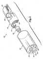
- FIGURE 1a brief overview of certain aspects of the exemplary authorization system 100 for a single use imaging device is illustrated by FIGURE 1 .
- the authorization system 100includes a verification object image 400 that is printed on a test target 410.
- a single use imaging device 120such as an endoscope, comprises a shaft 123 having a distal tip 122 that includes an imaging element and a proximal end 124 with a connector 128 that is attachable to a control unit 200.
- the single use imaging device 120also includes a breakout box 126 that is positioned approximately midway along the length of the endoscope.
- the breakout box 126provides an entrance to a working channel and may include additional attachment points for collection of samples and surgical manipulation.
- the control unit 200includes a device interface 210 and a network interface 220.
- the device interface 210allows the single use imaging device 120 to transfer a stored code in the format of an image signal to the control unit for analysis. While the illustrative embodiment of the system depicted in FIGURE 1 shows an endoscope as the imaging device, it will be understood by one skilled in the art that any type of single use imaging device can be used in accordance with the devices, systems and methods of the invention.
- FIGURE 2shows further detail of one embodiment of an imaging sensor assembly positioned at or adjacent to the distal tip 122 of an exemplary single use imaging device 120.
- the distal tip 122includes light illumination ports 130 and 132, an entrance to a working channel 134, a camera port 138 and a flushing cap 136.
- the imaging assemblyincludes a cylindrical lens assembly 140, and a pair of LEDs 142 and 144 bonded to a circuit board 152 which is affixed to a heat exchanger 146.
- Fitted to the rear of the heat exchanger 146is an image sensor 150 that preferably comprises a CMOS imaging sensor chip or other solid state imaging device.
- a circuit board or flex circuit 152is secured behind the image sensor 150 and contains circuitry to transmit and receive signals to and from the control unit 200.
- the image sensor 150is preferably a low light sensitive, low noise, CMOS color imager with VGA resolution or higher such as SVGA, SXGA, or XGA. If less resolution is required, a one-half VGA sensor could also be used.
- the video output of the systemmay be in any conventional digital or analog format, including PAL or NTSC or high definition video format.
- the image sensor 150comprises a VGA CMOS image sensor with 640 X 480 active pixels and an on-chip serializer that transmits image data to the control cabinet in a serial form.
- CMOS image sensoris available as Model No. MI-370 from Micron Electronics of Boise, Idaho. Further detail of the imaging system and its generation can be found in U.S. Patent No. 10/811,781 filed March 29, 2004 .
- the single use imaging device 120comprises a memory having a code stored therein that encodes a serial identifier uniquely associated with the imaging device.
- the codeis transferable to the control unit in the same format as image signals are transmitted to the control unit 200 for analysis.
- the memorymay be provided in the circuit board 152 and coupled to the image sensor 150, or the memory may be integrated within the image sensor 150. Alternatively memory chips may also be added at, or adjacent to, the proximal end 122 of the imaging device 120.
- the memorycan be any digital memory which is designed to store individual bits of information. Code information such as a program or data can be programmed into a memory chip at the time of manufacture.
- Code information encoding a unique serial identifier or a verification object image embedding a codecan be programmed or "burned" into the chip at the time of manufacture.
- the serial identifieris in general a character string of sufficient length to uniquely characterize a single unit from within large production runs.
- the identifiercould be similar to the codes used in familiar UPC barcodes (see, e.g., the Uniform Code Council, Inc., Princeton Pike Corporate Center, 1009 Lenox Drive, Suite 202, Lawrenceville, NJ 08648) or more extensive codes such as web addresses (uniform resource locators, URLs).
- the character stringcan be impressed upon an EPROM component included in the single use-device camera electronics or stored at manufacture in nonvolatile memory.
- the image sensor 150stores in its memory an image signal that contains the serial identifier used to authorize the single use device in the same format as the medical images obtained during clinical use of the device.
- the imaging device 120is capable of transferring the code containing a serial identifier in the format of the image signals produced by the image sensor to the control unit 200 for analysis.
- the data and control signalsare preferably sent differentially along a pair of twisted micro-coaxial cables.
- the stored code encoding the serial identifiercan be read as a video output signal by the control unit and used to determine if use of the imaging device is authorized.
- the present inventionprovides a control unit 200 for authorizing a single use imaging device comprising an interface that is capable of receiving an electronic image that includes a unique serial identifier.
- the codemay be stored in the memory of a single use imaging device as described above, or, alternatively, the code may be embedded in a verification object image that is obtained from a test target associated with the single use imaging device as further described below.
- FIGURE 3is a block diagram of an illustrative architecture for a control unit 200 containing a computer 205 in accordance with this aspect of the invention.
- the computer 205may include additional components. However, it is not necessary that all of these generally conventional components be shown in order to disclose an illustrative embodiment of the invention.
- the exemplary embodiment of the control unit 200 shownincludes a network interface 220, a processing unit 230, a device interface 210, a display 240 and an image processor 242 that are connected to the processing unit 230.
- the computer 205also includes a memory 252 that stores a serial identifier database 258, an image recognition program 256, a calibration program 260, and an operating system 262.
- the memory 252, display 240, network interface 220, and device interface 210are all connected to the processor 230 via a bus. Other peripherals may also be connected to the processor in a similar manner.
- the embodiment of the computer 205 shown in FIGURE 3contains a calibration program 260 and a local database 258, these features are optional and not required in some embodiments of the invention.
- the calibration program 260interfaces with a servo motor controller (not shown) that in turn controls a number of servo motors. Each of the servo motors is connected to one or more control cables within the endoscope. Motion of the servo motors pulls or releases the control cables in order to change the orientation of the distal tip 122 of the imaging device 120.
- the network interface 220includes the necessary circuitry for connecting the computer 205 directly to a LAN or WAN, or for connecting remotely to a LAN or WAN with various communication protocols, such as the TCP/IP protocol, the Internet Inter-ORB protocol, any of various wireless protocols (e.g., the IEEE 802.1x family) and the like.
- the device interface 210includes hardware and software components that facilitate interaction with a device that provides an input digital image, such as an electronic image sensor ( FIGURE 2 ).
- the interfacecan receive an input digital signal via a wired connection, or alternatively, via a wireless signal from the single use imaging device.
- the processing unit 230is of sufficient power and speed to provide processing of an input digital image either alone or in cooperation with the image processor 242.
- the memory 252generally comprises a random access memory (“RAM”), a read-only memory (“ROM”) and a permanent mass storage device, such as a hard disk drive, tape driver, optical drive, floppy drive, CD-ROM, DVD-ROM or removable storage drive.
- RAMrandom access memory
- ROMread-only memory
- the memory 252stores an operating system 262 for controlling operation of the computer 205.
- the imaging element in the distal tip 122 of the device 120becomes activated and captures an image of the verification object 400 that is printed on the test target 410 ( FIGURE 1 ).
- the image of verification object 400is pre-stored in the memory of the single use device ( FIGURE 2 ) as a code at the time of manufacture.
- the image of verification object 400is transferred from the endoscope imaging element (or other memory) to the control unit 200.
- the computer 205 and the image processor 242receives the image of the verification object and extracts the serial identifier of the single use imaging device.
- the processor 230 and/or the image processorexecutes an image decoder program that detects digitized bar space patterns or other predetermined spatial, color or numeric codes to detect the serial number.
- the authorization system 100authorizes the device for use by comparing the serial identifier to a database of authorized serial identifiers.
- the serial identifier database 258is stored locally in the memory 252 of the computer 205 contained within the control unit 200, and the determination is made using the recognition program 256.
- the database 258may be downloaded from a remote location such as from the manufacturer of the single use imaging device into the memory of the computer 205 via a local area network.
- serial identifier database 258may also be provided on a CD-ROM or other machine-readable storage medium and accessible via the network interface 220 or by using a CD-ROM drive within the control unit 200 itself.
- the serial number databasemay also include additional information such as model information, product recall notices, product parameter updates, and the like.
- the serial number database 258is located at a remote central server that registers the use of single use imaging devices and marks a particular device as having been used to prevent future authorization.
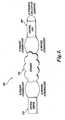
- FIGURE 4illustrates the operation of a remote authorization system 300 to transfer authorization information regarding a particular serial identifier between the control unit 200 connected to the single use imaging device 120 and a remote central server 330 accessible via the Internet 320.
- a usermay be positioned in front of a display device 240 connected to the control unit 200 and may initiate a request for authorization of a single use imaging device based upon the serial identifier decoded from the verification object.
- a request for authorizationmay be automatically initiated by the control unit 200 via the network interface 220 ( FIGURE 1 ).
- two-way communicationmay be initiated by accessing the central server 330 from the control unit 200.
- the control unit 200may configure the transmission of a request for authorization for a particular serial identifier, as shown in the embodiment of system 300 depicted in FIGURE 4 .
- the central server 330receives the serial identifier and sends an appropriate response as to whether the device is authorized to the control unit 200 via the Internet 320.
- the remote central servercomprises a registry that tracks usage information of single use medical devices.
- the verification object image 400is printed onto a test target 410 that is associated with the imaging device 120 at the time of its manufacture.
- the serial identifier encoded in the verification object imagecan be any combination of letters, symbols, characters, colors or patterns capable of uniquely identifying a single use imaging device.
- a serial identifiercan be encoded in any type of machine readable image, such as a linear bar code or a two-dimensional bar code as further described below.
- FIGURES 5A and 5Billustrate a verification object image 400A,B printed on a test target 410A,B.
- the verification object image 400A,Bincludes an encoded serial identifier 420A,B that is uniquely associated with a single use device at time of its manufacture.
- the verification object images 400A,Badditionally include a set of imaging calibration objects 430 A-H.
- the serial identifieris encoded in a linear bar code 420A.
- the exemplary linear bar code 420A illustrated in FIGURE 5Ais a series of vertical lines of varying widths (called bars) and spaces. Different combinations of the bars and spaces represent different characters.
- the processor 230 or image processorexecutes a bar code reading program that detects the patterns of bars and spaces in the image of the verification object.
- the linear bar code 420Amay represent numeric characters only (e.g., UPC, EAN, Interleaved 2 of 5), or may represent both numbers and alphabetic characters (e.g., Code 93, Code 128 and Code 39).
- the serial identifieris encoded in a two-dimensional bar code 420B.
- the two-dimensional bar code 420Bstores information along the height as well as the length of the symbol.
- Illustrative non-limiting examples of two-dimensional bar codes useful in the present inventioninclude stacked bar codes, PDF417 codes, and data matrix codes.
- the serial identifier 420A,B of the single use device 120will comply with the voluntary labeling standards developed by the Health Industry Business Communications Council (HIBCC).
- the HIBCC labeler identification code (LIC) primary data structurespecifies the use of either Code 128 or Code 39 symbology which utilize an alphanumeric character set.
- the 36 alpha and numeric characterscombined with the flexibility of a 1-13 digit variable length format provide over 75 million trillion identifiers, thereby vastly reducing the possibility of duplicate identifiers in the same database.
- HIBCC standardsfurther specify the use of two-dimensional symbologies, such as data matrix and PDF417 for small device and instrument marking (see " The Health Industry Bar Code Supplier Labeling Standard," American National Standards Institute, Inc. (ANSI), Health Industry Business Communications Council, 2525 East Arizona Biltmore Circle, Suite 127, Phoenix, AZ 85016 ).
- the verification objects 400A,B that are printed on the test targets 410A,Binclude a set of calibration objects.
- FIGURE 5A and 5Billustrate an exemplary set of calibration objects 430A-H useful for calibrating the imaging element of the single use imaging device 120.
- Each calibration object 430A-His positioned at predetermined point coordinates within the verification object image. The positioning of the calibration objects 430A-H allows an imaging device to capture the verification object image 400A,B, and to determine if the position of the calibration objects is distorted in comparison to a pre-set standard with respect to focus, radial distortion, warping, and the like.
- the calibration objects 430A-Hmay also be positioned on various surfaces in order to test the motor and steering function of the image device 120.
- the pre-set standardmay be stored as code within the single use device and transmitted to the imaging board in the format of an imaging signal as previously described. Alternatively, the pre-set standard may be stored locally in the control unit or obtained via a network connection upon authorization.
- the image of verification object 400A,Bmay be captured from the test target 410A,B using the imaging device 120 at various deflection angles or focal lengths/zoom settings (if available).
- the calibration objects 430A-Hare compared to the pre-set standards using the calibration program 260. Once a distortion or other discrepancy is detected, a set of coefficients is derived and used to perform a corrective calibration, if necessary, prior to clinical use of the device.
- the verification object 400A,Bcontains at least four calibration objects.
- the verification object image 400A,Bcontains at least seven calibration objects 430A-H.
- the identical calibration objectis positioned at two or more different predetermined locations within the verification object as shown in FIGURES 5A,B calibration objects 430A-H.
- two or more calibration objects within a particular verification object imageare different from one another (see FIGURES 5A,B calibration objects 430A and 430H).
- a principal calibration objectmay be designated in the center of the image.
- an orientation calibration objectmay also be designated.
- the pixel aspect ratio of the imaging elementcan be calibrated based on detection of the pixel value of the calibration objects in order to adjust contrast, white-balance and exposure control of the imaging device.
- a set of calibration objectsare provided without a serial identifier.
- test target 410A,Bcan be any item upon which the verification object 400A,B associated with the device 120 can be printed and that is accessible to the imaging element in the distal tip 122.
- test target 410A,Bmay be printed on packaging associated with the device 120 or on an accessory such as a cap, cable, or other accessory.
- the test target 410A,Bis imprinted directly onto the device 120 at a position where the image sensor can be positioned to capture an image of the verification object.
- the test target 410A,Bis provided on a three dimensional structure such that the calibration objects 430 A-H are positioned at various deflection angles with respect to the position of the distal tip 122 of the imaging device 120.
- a set of calibration objectscould include targets at the corners of the specified deflection range, which would be imaged in sequence to verify that the navigation function is working correctly and the device can be steered, e.g., to its up/down/left/right limits.
- These calibration objectscould include encoded identifiers of their location, so that the response to simulated user commands regarding position and transit time can be measured, compared to quality assurance criteria, passed with respect to acceptability thresholds (which can be tailored to individual users and procedures) and reported to a central database.
- the three dimensional positioning of the calibration objects 430 A-Hprovides objects with which to test the steering and motor functions of the single use imaging device 120.
- the test target 410A,Bmay be printed on various surfaces of a hood that is placed over the distal tip 122.
- the test target 410A,Bmay be printed on several panels of packaging material provided with the device.
- the packaging materialmay be folded into various shapes, such as a box shape to allow for image capture at various deflection angles.
- the test targets 410A,Bare positioned at an appropriate distance for the focal properties of the imaging device 120.
- the printed verification object imagecontains an encoded serial identifier uniquely associated with a particular single use device.
- the printed verification object imagecontains both an encoded unique serial identifier and a set of calibration objects.
- the set of calibration objectsare identical for a particular set of devices, such as a particular model of device, while the serial identifiers are different for each device.
- the verification object 400A,Bcan be printed on the test target 410A,B using labeling software with a printer (dot matrix, laser or inkjet printer) and affixing the image to the test target 410A,B, or by printing the verification object image 400A,B with a specialized bar code label printer.
- a printerdot matrix, laser or inkjet printer
- verification object images in the form of data matrixcan be etched directly onto a single use device 120.
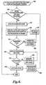
- FIGURE 6is a flow chart of a process for remote authorization using a verification object.
- the remote authorization processbegins at 600 and comprises requesting an electronic image of the verification object associated with the single use device at 610, and obtaining the verification object image at 620.
- the control unitrequests the verification image after the single use device is connected to the control unit.
- the electronic imageis obtained from the memory of the single use device.
- the electronic imageis obtained using the imaging sensor of the single use device. Once the machine obtains the electronic image, the image is decoded to extract the serial identifier at 630.
- the machinethen sends the serial identifier information to a remote server with an authentication database at 640.
- a testis made at 650 to determine if the serial identifier is valid. If not, the remote server sends a message to the user that the device is not authorized at 660, and there is no activation. If the remote server verifies that the serial identifier is authorized, a message is sent that the identifier is valid at 650 and activation of the device is allowed at 670. The activation of the device triggers a message to the remote server to flag the database or otherwise indicate that the device has been used at 680.
- the use of the remote authorization method of the inventionallows a service provider of a central server, such as a manufacturer of a device, to maintain a registry of new authorized devices associated with unique serial identifiers and to prevent unauthorized use or reuse of a device.
- a service provider of a central serversuch as a manufacturer of a device
- the serial identifieris flagged or otherwise marked as having been used so that the identical identifier will not be authorized for future use.
- the authorization informationcan be returned to the client.
- There are various suitable methods for providing user registration and tracking of single use imaging devicesincluding, for example, sending the serial identifier to a Web server application with an automatic real-time response.
- the service providercan determine that the device is new, and also provide important upgrades prior to unlocking features required for activation, thus maintaining control over single use devices.
- the use of the remote authorization methodallows a central server to verify that the client is a licensed customer, by receiving an identification number associated with the client when the request for authorization is made.
- the central servermay require information in addition to the serial identifier such as the control unit serial number, the client's name and location, and the like before the device is authorized for use.
- FIGURE 7is a flow diagram of a process for local authorization and activation using a verification object.
- the local authorization processstarts at 700 and comprises requesting an electronic image of the verification object associated with the single use device at 710, and obtaining the verification object image 720.
- the control unitobtains the electronic image, the image is decoded to extract the serial identifier at 730.
- the control unitthen obtains data for a verification at 740 from a local database at 750.
- the control unitverifies that the serial identifier is authorized at 760 by comparing the serial identifier to information in the database using a set of predetermined rules for authorization.
- the local databasecontains a list of authorized serial identifiers provided by the manufacturer of the single use device which may be entered into the control unit via a CD-ROM, or other form of electronic download such as a periodic Internet update.
- authorization datamay include the serial identifiers, as well as other information for updating the rules for authorization.
- the authorization rules and serial identifiersmay be dynamically updated so that a control unit receives and maintains authorization rules and data that are current. A test is made to determine if the serial identifier is valid at 770. If not, the control unit provides a message to the user at 780 that the device is not authorized, and there is no activation.
- the single use deviceis authorized and activated at 790.
- the control unitUpon activation, the control unit sends a message to the database at 750 to set a flag or otherwise indicate that the device has been used at 795. This indication in the database allows a user to track the usage of the single use device and to verify that any imaging device connected to the control unit is new and unused.
- a calibration and self-test processbegins at 800 and comprises obtaining authorization based on a valid identifier at 810 and initiating a calibration mode at 820.
- the calibration modecalibration objects obtained from the verification object image are compared to pre-set standards at 830.
- a testis made at 835 to determine if the calibration parameters are valid. If not, a corrective calibration is performed at 840, a new image of the verification object is captured at 845, and the calibration objects from the most recent verification object image are compared to the pre-set standards at 830.
- the control unitinitiates a functional self-test at 850.
- the self-test parametersare updated during the authorization process.
- Self-test parametersmay include navigation functions such as motor functions, steering and braking functions, transient response, position accuracy or error, and imaging functions like color fidelity, balance, sensitivity, linearity across a field, glare, blooming, etc.
- a messageis returned to the user that the functional test failed at 860.
- the single use deviceis activated for use at 870. Upon activation, a message is sent to the database to set a flag or otherwise indicate that the device is used at 880.
- a corrective calibration and functional testingmay be automatically performed by the control unit using predetermined algorithms, or alternatively, these functions may be performed by the user utilizing user-interactive commands.
- a calibration and functional self-test processbegins at 900 and comprises obtaining authorization based on a valid identifier at 910 and initiating a calibration mode at 920.
- the calibration modecalibration objects obtained from the verification object image are compared to pre-set standards at 930.
- a testis made at 935 to determine if the calibration parameters are valid. If not, a corrective calibration is performed at 940, a new image of the verification object is captured at 945, and the calibration objects from the most recent verification object image are compared to the pre-set standards at 930.
- the control unitinitiates a functional self-test at 950.
- a navigation programis activated that actuates servo motors connected to cables inside the single use imaging device at 955.
- the distal tip of the imaging deviceis deflected at various angles (left, right, up, down, and the like) in order to aim at and capture an image of each calibration object at 960.
- the imageis compared to pre-set standards for each location at 965.
- a testis made at 970 to determine if the device functional parameters are valid.
- the functional parametersmay include motor functions, steering and capture of images at predetermined locations.
- the devicefails the functional self-test at 970, a message is returned to the use that the functional test failed at 975. If the device passes the functional self-test, the single use device is activated for use at 980. Upon activation, a message is sent to the database to set a flag or otherwise indicate that the device is used at 985.
- the calibration and functional self-testing functionsmay be accomplished in a variety of sequential steps. For example, a functional self-test may be performed prior to or concurrent with the steps of calibration.
- the methods of this aspect of the inventioncomprise assigning a unique serial identifier to each single use imaging device to be manufactured, encoding the serial identifier in a verification object image, and associating the serial identifier with the device at the time of manufacture.
- the verification object imagemay also include a set of calibration objects, thereby allowing a device to be authorized and calibrated using the same captured validation object image.
- the methodfurther includes maintaining a database of authorized serial identifiers corresponding to manufactured serialized medical devices to users.
- the user of the medical devicemay determine if a particular device is authorized by comparing the unique serial identifier to the database of manufactured serialized medical devices by utilizing the systems and methods of the invention previously described.
- the method of calibration using a captured validation objectmay be performed as described herein.
Landscapes
- Health & Medical Sciences (AREA)
- Life Sciences & Earth Sciences (AREA)
- Surgery (AREA)
- Engineering & Computer Science (AREA)
- Medical Informatics (AREA)
- General Health & Medical Sciences (AREA)
- Pathology (AREA)
- Veterinary Medicine (AREA)
- Nuclear Medicine, Radiotherapy & Molecular Imaging (AREA)
- Public Health (AREA)
- Biomedical Technology (AREA)
- Heart & Thoracic Surgery (AREA)
- Animal Behavior & Ethology (AREA)
- Molecular Biology (AREA)
- Physics & Mathematics (AREA)
- Optics & Photonics (AREA)
- Biophysics (AREA)
- Radiology & Medical Imaging (AREA)
- Signal Processing (AREA)
- Oral & Maxillofacial Surgery (AREA)
- Multimedia (AREA)
- Computer Vision & Pattern Recognition (AREA)
- General Physics & Mathematics (AREA)
- Theoretical Computer Science (AREA)
- Endoscopes (AREA)
- Instruments For Viewing The Inside Of Hollow Bodies (AREA)
Description
- The present invention relates to serialization of medical devices in general and single use imaging devices in particular.
- As an aid to the early detection of disease, it has become well established that there are major public health benefits from regular endoscopic examinations of internal structures such as the alimentary canals and airways, e.g., the esophagus, lungs, colon, uterus, and other organ systems. A conventional imaging endoscope used for such procedures comprises a flexible tube with a fiber optic light guide that directs illuminating light from an external light source to the distal tip where it exits the endoscope and illuminates the tissue to be examined. An objective lens and fiber optic imaging light guide communicating with a camera at the proximal end of the scope, or an imaging camera chip at the distal tip, produce an image that is displayed to the examiner.
- Navigation of the endoscope through complex and tortuous paths is critical to success of the examination with minimum pain, side effects, risk or sedation to the patient. To this end, modern endoscopes include means for deflecting the distal tip of the scope to follow the pathway of the structure under examination, with minimum deflection or friction force upon the surrounding tissue. Control cables similar to puppet strings are carried within the endoscope body in order to connect a flexible portion of the distal end to a set of control knobs at the proximal endoscope handle. By manipulating the control knobs, the examiner is able to steer the endoscope during insertion and direct it to a region of interest.
- Conventional endoscopes are expensive medical devices costing in the range of $25,000 for an endoscope, and much more for the associated operator console. Because of the expense, these endoscopes are built to withstand repeated disinfections and use upon many patients. Conventional endoscopes are generally built of sturdy materials, which decreases the flexibility of the scope and thus can decrease patient comfort. Furthermore, conventional endoscopes are complex and fragile instruments that frequently need expensive repair as a result of damage during use or during a disinfection procedure.
- Single use disposable medical devices have become popular for instruments with small lumens and intricate, delicate working mechanisms that are difficult to sterilize or clean-properly. Single, use disposable devices packaged in sterile wrappers avoid the risk of pathogenic cross-contamination of diseases such as HIV, hepatitis, and other pathogens. Hospitals generally welcome the convenience of single use disposable products because they no longer have to be concerned with product age, overuse, breakage, malfunction and sterilization. However, with the advent of single use devices comes the need for authorization of a particular device prior to use to determine if it is new or used, that associated console software is up-to-date (e.g., sensitivity and color calibration tables, steering algorithms, etc.), when and where it was manufactured, whether it is a current model, and information regarding recall notices. Therefore, in order to prevent improper use of single use devices, :here is a need for a method of serializing a device so that prior to use, the user can be assured that the system is current, all elements are compatible, and the device can be authorized as new and unused, and ready for use.
US 2002/0114452 describes a system for digital image authentication in which a serial number is associated with a camera and may be used to encrypt an image generated at the camera. The encrypted image is then communicated to an authorization centre where is can be decrypted and verified using the serial number.JP 10 033472 US 2003/009083 describes an endoscope system including a database and a database managing device. The database is configured to store a plurality of pieces of endoscope data. Each piece of the endoscope data corresponds to a different endoscope and is associated with ownership information indicating a term for which the corresponding endoscope is allowed to be utilized.- To address these and other problems in the prior art, the present invention provides a single use medical imaging device according to
claim 1, a medical imaging system according to claim 18, a medical imaging system according to claim 12 and a method of authorizing a single use medical imaging device according to claim 20. Described herein is a single use imaging device having a shaft with a proximal and dista end and a connector on the proximal end for connecting the device to a control unit. An image sensor is included at or adjacent to the distal end for producing images in a predefined format for receipt by an imaging board within the control unit. The device includes a memory with a stored code encoding a serial identifier transferable to the control unit for analysis, wherein the serial identifier is uniquely associated with the imaging device at the time of manufacture. A transmit circuit is included that transmits the code to the imaging board in the format of the image signals produced by the image sensor. - Also described is a control unit for authorizing a single use medical imaging device. The control unit comprises a connector for connecting the control unit to the single use medical imaging device and a device interface capable of receiving a code in a format of an image signal produced by an image sensor of the medical imaging device, wherein the code encodes a serial identifier uniquely associated with the single use imaging device. The control unit includes a processor that extracts the serial identifier from the code, and means for determining if the single use device is authorized based upon the serial identifier associated with the device. In some embodiments, the processor further includes logic for calibrating the single use imaging device upon authorization. In some embodiments, calibration includes imaging properties and also the navigation characteristics such as deflection ranges and sensitivities, dynamic and static, of the single use device. In further embodiments, the memory comprises logic for functionally testing the single use imaging device upon successful calibration.
- Also described is a medical imaging system comprising a single use medical imaging device having an image of a verification object encoding a serial identifier uniquely associated with the device and a control unit for authorizing a single use medical imaging device. The control unit has a device interface capable of receiving the image of the verification object and means for determining if the single use device is authorized based upon the serial identifier encoded in the image. In some embodiments, the verification object image is stored in the memory of the single use device. In other embodiments, the verification object image is printed on a test target associated with the single use device. In some embodiments, the device is authorized by reference to a registry contained in a remote database accessible from the control unit via a network connection.
- Also described are methods for authorizing a single use imaging device. The methods comprise connecting the imaging device to a control unit, electronically obtaining an image of a prerecorded verification object associated with the imaging device, wherein the verification object encodes a serial identifier, extracting the serial identifier from the image, and authorizing the imaging device by comparing the serial identifier to a database containing information on authorized serial identifiers. A match between the serial identifier and information in the database results in the device being authorized for use. In some embodiments, the comparison is made to a remote database by connecting to a remote server. In some embodiments, the authentication method further comprises automatic calibration and functional self-testing.
- Also described are methods for serializing a set of single use imaging devices comprising assigning a unique serial identifier to each device to be manufactured, encoding the serial identifier in a verification object image, wherein the verification object image also includes a set of calibration objects, associating the verification object with each imaging device at the time of its manufacture, and maintaining a registry of authorized serial identifiers corresponding to manufactured serialized imaging devices, wherein a user of an imaging device may determine if the device is authorized by comparing the serial identifier to the registry.
- The foregoing aspects and many of the attendant advantages of this invention will become more readily appreciated as the same become better understood by reference to the following detailed description, when taken in conjunction with the accompanying drawings, wherein:
FIGURE 1 is a schematic diagram illustrative of a system for authorizing a single use imaging device in accordance with an embodiment of the present invention;FIGURE 2 is a schematic diagram of an imaging system of a single use imaging device in accordance with an embodiment of the present invention;FIGURE 3 is a block diagram of an illustrative architecture for a control unit for a single use imaging device in accordance with the present invention;FIGURE 4 illustrates the transfer of authorization data between a control unit and a remote central server in accordance with one embodiment of the present invention;FIGURE 5A illustrates an embodiment of a verification object image that encodes a serial identifier in the form of a linear bar code and a set of calibration objects;FIGURE 5B illustrates an embodiment of a verification object image that encodes a serial identifier in the form of a two-dimensional bar code and a set of calibration objects;FIGURE 6 is a flow diagram of a process for remotely authorizing use of a single use medical device according to another embodiment of the method of the invention;FIGURE 7 is a flow diagram of a process for locally authorizing use of a single use medical device according to another embodiment of the method of the invention;FIGURE 8 is a flow diagram of a process for authorization, calibration and self-testing in accordance with another embodiment of the present invention; andFIGURE 9 is a flow diagram of a process for authorization, calibration and self-testing in accordance with yet another embodiment of the present invention.- Unless specifically defined herein, all terms used herein have the same meaning as they would be understood by those of ordinary skill in the art of the present invention. The following definitions are provided in order to provide clarity with respect to the terms as they are used in the specification and claims to describe the present invention.
- As used herein, the term "verification object image" refers to any machine-readable image or portion thereof that is capable of encoding a serial identifier that is uniquely associated with a particular single use imaging device. A verification object image may include an encoded serial identifier and a set of imaging calibration objects. As used herein, the term "serial identifier" refers to any combination or arrangement of numbers, letters, symbols, characters, colors or patterns capable of uniquely identifying a single use imaging device. Typically, a serial identifier comprises at least 10 characters and may be many more, including possibly an Internet web address or URL. Examples of verification object images capable of encoding serial identifiers used in accordance with the devices, systems and methods of the invention include linear bar codes and two-dimensional bar codes as further described below.
- Generally described, the present invention provides a system, device, and method for authorizing a single use imaging device prior to use. Single use imaging devices, such as endoscopes, imaging catheters, fiber optic guide wires and the like are useful to avoid the need to sterilize and repair complex and fragile instruments that frequently need expensive repair as a result of damage during use or during a disinfection procedure. The devices, systems and methods of the invention may be used to authorize single use imaging devices through the use of a unique serial identifier that is encoded in a verification object image that is associated with a single use device at the time of manufacture. In some embodiments, the code encoding the serial identifier is stored in the memory of the single use device. In other embodiments, the serial identifier is encoded in a verification object image that is printed on a test target that is associated with the single use device at the time of manufacture. In numerous embodiments, a remote central server authorizes the device. In further embodiments, the verification object is an image that includes an encoded serial identifier and a set of imaging calibration objects.
- The various embodiments of the devices, systems and methods of the present invention may be used by any user who would benefit from devices, systems and methods for authenticating an imaging device, such as, for example, manufacturers and retailers of medical devices, physicians, surgeons, and other medical personnel, as well as patients. For example, the devices, systems and methods of the invention may be used to verify that a single use medical device is new and unused, of current production, and to further update operation parameters as well as to obtain recall information from a remote central registry.
- The detailed description is divided into six sections. In the first section, a brief introductory overview of the system for authorizing a single use imaging device is provided. In the second section, a device in the form of a single use imaging device comprising a memory with a stored code encoding a serial identifier is presented. In the third section, a device in the form of a control unit that interfaces with a single use imaging device in accordance with one embodiment of the invention is presented. In the fourth section, a medical imaging system comprising a single use imaging device with a verification object image is provided. In the fifth section, a method for authorizing a single use imaging device is presented. Finally, in the sixth section, a method of serializing single use imaging devices is described.
- For ease of understanding, a brief overview of certain aspects of the
exemplary authorization system 100 for a single use imaging device is illustrated byFIGURE 1 . Theauthorization system 100 includes averification object image 400 that is printed on atest target 410. A singleuse imaging device 120, such as an endoscope, comprises ashaft 123 having adistal tip 122 that includes an imaging element and aproximal end 124 with aconnector 128 that is attachable to acontrol unit 200. Proximal to thedistal tip 122 is an articulation joint 125 that provides sufficient flexibility to the distal section of the shaft such that thedistal tip 122 can be directed over the required deflection range (180° or more) by the steering mechanism and can be directed to make that bend in any direction desired about the circumference of the distal tip. In the embodiment shown, the singleuse imaging device 120 also includes abreakout box 126 that is positioned approximately midway along the length of the endoscope. Thebreakout box 126 provides an entrance to a working channel and may include additional attachment points for collection of samples and surgical manipulation. Thecontrol unit 200 includes adevice interface 210 and anetwork interface 220. Thedevice interface 210 allows the singleuse imaging device 120 to transfer a stored code in the format of an image signal to the control unit for analysis. While the illustrative embodiment of the system depicted inFIGURE 1 shows an endoscope as the imaging device, it will be understood by one skilled in the art that any type of single use imaging device can be used in accordance with the devices, systems and methods of the invention. FIGURE 2 shows further detail of one embodiment of an imaging sensor assembly positioned at or adjacent to thedistal tip 122 of an exemplary singleuse imaging device 120. Thedistal tip 122 includeslight illumination ports channel 134, acamera port 138 and aflushing cap 136. With continued reference toFIGURE 2 , the imaging assembly includes acylindrical lens assembly 140, and a pair ofLEDs circuit board 152 which is affixed to aheat exchanger 146. Fitted to the rear of theheat exchanger 146 is animage sensor 150 that preferably comprises a CMOS imaging sensor chip or other solid state imaging device. A circuit board orflex circuit 152 is secured behind theimage sensor 150 and contains circuitry to transmit and receive signals to and from thecontrol unit 200. Theimage sensor 150 is preferably a low light sensitive, low noise, CMOS color imager with VGA resolution or higher such as SVGA, SXGA, or XGA. If less resolution is required, a one-half VGA sensor could also be used. The video output of the system may be in any conventional digital or analog format, including PAL or NTSC or high definition video format. In some embodiments, theimage sensor 150 comprises a VGA CMOS image sensor with 640 X 480 active pixels and an on-chip serializer that transmits image data to the control cabinet in a serial form. Such a CMOS image sensor is available as Model No. MI-370 from Micron Electronics of Boise, Idaho. Further detail of the imaging system and its generation can be found inU.S. Patent No. 10/811,781 filed March 29, 2004 - In some embodiments of the present invention, the single
use imaging device 120 comprises a memory having a code stored therein that encodes a serial identifier uniquely associated with the imaging device. The code is transferable to the control unit in the same format as image signals are transmitted to thecontrol unit 200 for analysis. The memory may be provided in thecircuit board 152 and coupled to theimage sensor 150, or the memory may be integrated within theimage sensor 150. Alternatively memory chips may also be added at, or adjacent to, theproximal end 122 of theimaging device 120. The memory can be any digital memory which is designed to store individual bits of information. Code information such as a program or data can be programmed into a memory chip at the time of manufacture. Code information encoding a unique serial identifier or a verification object image embedding a code can be programmed or "burned" into the chip at the time of manufacture. The serial identifier is in general a character string of sufficient length to uniquely characterize a single unit from within large production runs. The identifier could be similar to the codes used in familiar UPC barcodes (see, e.g., the Uniform Code Council, Inc., Princeton Pike Corporate Center, 1009 Lenox Drive, Suite 202, Lawrenceville, NJ 08648) or more extensive codes such as web addresses (uniform resource locators, URLs). The character string can be impressed upon an EPROM component included in the single use-device camera electronics or stored at manufacture in nonvolatile memory. In a preferred embodiment of the invention, theimage sensor 150 stores in its memory an image signal that contains the serial identifier used to authorize the single use device in the same format as the medical images obtained during clinical use of the device. - In accordance with this aspect of the invention, the
imaging device 120 is capable of transferring the code containing a serial identifier in the format of the image signals produced by the image sensor to thecontrol unit 200 for analysis. In order to transmit serial image data and control signals along the length of the endoscope, the data and control signals are preferably sent differentially along a pair of twisted micro-coaxial cables. The stored code encoding the serial identifier can be read as a video output signal by the control unit and used to determine if use of the imaging device is authorized. - In another aspect, the present invention provides a
control unit 200 for authorizing a single use imaging device comprising an interface that is capable of receiving an electronic image that includes a unique serial identifier. The code may be stored in the memory of a single use imaging device as described above, or, alternatively, the code may be embedded in a verification object image that is obtained from a test target associated with the single use imaging device as further described below. FIGURE 3 is a block diagram of an illustrative architecture for acontrol unit 200 containing acomputer 205 in accordance with this aspect of the invention. Those of ordinary skill in the art will appreciate that thecomputer 205 may include additional components. However, it is not necessary that all of these generally conventional components be shown in order to disclose an illustrative embodiment of the invention. As shown inFIGURE 3 , the exemplary embodiment of thecontrol unit 200 shown includes anetwork interface 220, aprocessing unit 230, adevice interface 210, adisplay 240 and an image processor 242 that are connected to theprocessing unit 230. Thecomputer 205 also includes amemory 252 that stores aserial identifier database 258, animage recognition program 256, acalibration program 260, and anoperating system 262. Thememory 252,display 240,network interface 220, anddevice interface 210 are all connected to theprocessor 230 via a bus. Other peripherals may also be connected to the processor in a similar manner. Although the embodiment of thecomputer 205 shown inFIGURE 3 contains acalibration program 260 and alocal database 258, these features are optional and not required in some embodiments of the invention. In some embodiments of the invention, thecalibration program 260 interfaces with a servo motor controller (not shown) that in turn controls a number of servo motors. Each of the servo motors is connected to one or more control cables within the endoscope. Motion of the servo motors pulls or releases the control cables in order to change the orientation of thedistal tip 122 of theimaging device 120.- Those of ordinary skill in the art will appreciate that the
network interface 220 includes the necessary circuitry for connecting thecomputer 205 directly to a LAN or WAN, or for connecting remotely to a LAN or WAN with various communication protocols, such as the TCP/IP protocol, the Internet Inter-ORB protocol, any of various wireless protocols (e.g., the IEEE 802.1x family) and the like. Thedevice interface 210 includes hardware and software components that facilitate interaction with a device that provides an input digital image, such as an electronic image sensor (FIGURE 2 ). The interface can receive an input digital signal via a wired connection, or alternatively, via a wireless signal from the single use imaging device. Theprocessing unit 230 is of sufficient power and speed to provide processing of an input digital image either alone or in cooperation with the image processor 242. - With continued reference to
FIGURE 3 , thememory 252 generally comprises a random access memory ("RAM"), a read-only memory ("ROM") and a permanent mass storage device, such as a hard disk drive, tape driver, optical drive, floppy drive, CD-ROM, DVD-ROM or removable storage drive. Thememory 252 stores anoperating system 262 for controlling operation of thecomputer 205. - In operation of one embodiment of the
authorization system 100, upon attachment of theimaging device 120 to thecontrol unit 200, the imaging element in thedistal tip 122 of thedevice 120 becomes activated and captures an image of theverification object 400 that is printed on the test target 410 (FIGURE 1 ). In another embodiment of theauthorization system 100, the image ofverification object 400 is pre-stored in the memory of the single use device (FIGURE 2 ) as a code at the time of manufacture. The image ofverification object 400 is transferred from the endoscope imaging element (or other memory) to thecontrol unit 200. Thecomputer 205 and the image processor 242 receives the image of the verification object and extracts the serial identifier of the single use imaging device. To decode the serial number, theprocessor 230 and/or the image processor executes an image decoder program that detects digitized bar space patterns or other predetermined spatial, color or numeric codes to detect the serial number. - Once the image of the
verification object 400 has been decoded into the serial identifier, theauthorization system 100 authorizes the device for use by comparing the serial identifier to a database of authorized serial identifiers. In some embodiments, as shown inFIGURE 3 , theserial identifier database 258 is stored locally in thememory 252 of thecomputer 205 contained within thecontrol unit 200, and the determination is made using therecognition program 256. Thedatabase 258 may be downloaded from a remote location such as from the manufacturer of the single use imaging device into the memory of thecomputer 205 via a local area network. Alternatively, periodic updates to theserial identifier database 258 may also be provided on a CD-ROM or other machine-readable storage medium and accessible via thenetwork interface 220 or by using a CD-ROM drive within thecontrol unit 200 itself. The serial number database may also include additional information such as model information, product recall notices, product parameter updates, and the like. - In another embodiment of the invention, the
serial number database 258 is located at a remote central server that registers the use of single use imaging devices and marks a particular device as having been used to prevent future authorization.FIGURE 4 illustrates the operation of aremote authorization system 300 to transfer authorization information regarding a particular serial identifier between thecontrol unit 200 connected to the singleuse imaging device 120 and a remotecentral server 330 accessible via theInternet 320. In operation, a user may be positioned in front of adisplay device 240 connected to thecontrol unit 200 and may initiate a request for authorization of a single use imaging device based upon the serial identifier decoded from the verification object. Alternatively, a request for authorization may be automatically initiated by thecontrol unit 200 via the network interface 220 (FIGURE 1 ). As shown inFIGURE 4 , two-way communication may be initiated by accessing thecentral server 330 from thecontrol unit 200. Once a connection has been established, thecontrol unit 200 may configure the transmission of a request for authorization for a particular serial identifier, as shown in the embodiment ofsystem 300 depicted inFIGURE 4 . Thecentral server 330 receives the serial identifier and sends an appropriate response as to whether the device is authorized to thecontrol unit 200 via theInternet 320. In some embodiments of theauthorization system 300, the remote central server comprises a registry that tracks usage information of single use medical devices. - In some embodiments of the
authorization system 100, as shown inFIGURE 1 , theverification object image 400 is printed onto atest target 410 that is associated with theimaging device 120 at the time of its manufacture. The serial identifier encoded in the verification object image can be any combination of letters, symbols, characters, colors or patterns capable of uniquely identifying a single use imaging device. A serial identifier can be encoded in any type of machine readable image, such as a linear bar code or a two-dimensional bar code as further described below.FIGURES 5A and 5B illustrate averification object image 400A,B printed on a test target 410A,B. Theverification object image 400A,B includes an encodedserial identifier 420A,B that is uniquely associated with a single use device at time of its manufacture. In the exemplary embodiments shown inFIGURE 5A and 5B , theverification object images 400A,B additionally include a set of imaging calibration objects 430 A-H. - In some embodiments, such as that shown in
FIGURE 5A , the serial identifier is encoded in alinear bar code 420A. As shown, the exemplarylinear bar code 420A illustrated inFIGURE 5A is a series of vertical lines of varying widths (called bars) and spaces. Different combinations of the bars and spaces represent different characters. To decode the serial number, theprocessor 230 or image processor executes a bar code reading program that detects the patterns of bars and spaces in the image of the verification object. For example, thelinear bar code 420A may represent numeric characters only (e.g., UPC, EAN,Interleaved 2 of 5), or may represent both numbers and alphabetic characters (e.g., Code 93,Code 128 and Code 39). - In other embodiments, such as that shown in
FIGURE 5B , the serial identifier is encoded in a two-dimensional bar code 420B. As illustrated inFIGURE 5B , the two-dimensional bar code 420B stores information along the height as well as the length of the symbol. Illustrative non-limiting examples of two-dimensional bar codes useful in the present invention include stacked bar codes, PDF417 codes, and data matrix codes. - In a preferred embodiment, the
serial identifier 420A,B of thesingle use device 120 will comply with the voluntary labeling standards developed by the Health Industry Business Communications Council (HIBCC). The HIBCC labeler identification code (LIC) primary data structure specifies the use of eitherCode 128 or Code 39 symbology which utilize an alphanumeric character set. The 36 alpha and numeric characters combined with the flexibility of a 1-13 digit variable length format provide over 75 million trillion identifiers, thereby vastly reducing the possibility of duplicate identifiers in the same database. HIBCC standards further specify the use of two-dimensional symbologies, such as data matrix and PDF417 for small device and instrument marking (see "The Health Industry Bar Code Supplier Labeling Standard," American National Standards Institute, Inc. (ANSI), Health Industry Business Communications Council, 2525 East Arizona Biltmore Circle, Suite 127, Phoenix, AZ 85016). - In further embodiments, the verification objects 400A,B that are printed on the test targets 410A,B include a set of calibration objects.
FIGURE 5A and 5B illustrate an exemplary set of calibration objects 430A-H useful for calibrating the imaging element of the singleuse imaging device 120. Each calibration object 430A-H is positioned at predetermined point coordinates within the verification object image. The positioning of the calibration objects 430A-H allows an imaging device to capture theverification object image 400A,B, and to determine if the position of the calibration objects is distorted in comparison to a pre-set standard with respect to focus, radial distortion, warping, and the like. The calibration objects 430A-H may also be positioned on various surfaces in order to test the motor and steering function of theimage device 120. The pre-set standard may be stored as code within the single use device and transmitted to the imaging board in the format of an imaging signal as previously described. Alternatively, the pre-set standard may be stored locally in the control unit or obtained via a network connection upon authorization. - The image of verification object 400A,B may be captured from the test target 410A,B using the
imaging device 120 at various deflection angles or focal lengths/zoom settings (if available). In operation, the calibration objects 430A-H are compared to the pre-set standards using thecalibration program 260. Once a distortion or other discrepancy is detected, a set of coefficients is derived and used to perform a corrective calibration, if necessary, prior to clinical use of the device. In some embodiments, theverification object 400A,B contains at least four calibration objects. In some embodiments, theverification object image 400A,B contains at least sevencalibration objects 430A-H. In some embodiments, the identical calibration object is positioned at two or more different predetermined locations within the verification object as shown inFIGURES 5A,B calibration objects 430A-H. In some embodiments, two or more calibration objects within a particular verification object image are different from one another (seeFIGURES 5A,B calibration objects 430A and 430H). In some embodiments, a principal calibration object may be designated in the center of the image. In addition, an orientation calibration object may also be designated. In addition to predetermined positions of the calibration objects, the pixel aspect ratio of the imaging element can be calibrated based on detection of the pixel value of the calibration objects in order to adjust contrast, white-balance and exposure control of the imaging device. In some embodiments, a set of calibration objects are provided without a serial identifier. - The test target 410A,B can be any item upon which the
verification object 400A,B associated with thedevice 120 can be printed and that is accessible to the imaging element in thedistal tip 122. For example, test target 410A,B may be printed on packaging associated with thedevice 120 or on an accessory such as a cap, cable, or other accessory. In some embodiments, the test target 410A,B is imprinted directly onto thedevice 120 at a position where the image sensor can be positioned to capture an image of the verification object. - In some embodiments, the test target 410A,B is provided on a three dimensional structure such that the calibration objects 430 A-H are positioned at various deflection angles with respect to the position of the
distal tip 122 of theimaging device 120. For example, a set of calibration objects could include targets at the corners of the specified deflection range, which would be imaged in sequence to verify that the navigation function is working correctly and the device can be steered, e.g., to its up/down/left/right limits. These calibration objects could include encoded identifiers of their location, so that the response to simulated user commands regarding position and transit time can be measured, compared to quality assurance criteria, passed with respect to acceptability thresholds (which can be tailored to individual users and procedures) and reported to a central database. - The three dimensional positioning of the calibration objects 430 A-H provides objects with which to test the steering and motor functions of the single
use imaging device 120. For example, the test target 410A,B may be printed on various surfaces of a hood that is placed over thedistal tip 122. As another example, the test target 410A,B may be printed on several panels of packaging material provided with the device. The packaging material may be folded into various shapes, such as a box shape to allow for image capture at various deflection angles. In such embodiments, the test targets 410A,B are positioned at an appropriate distance for the focal properties of theimaging device 120. - There are various methods of printing the
verification object 400 on thetest target 410 in accordance with some embodiments of this aspect of the invention. In some embodiments, the printed verification object image contains an encoded serial identifier uniquely associated with a particular single use device. In other embodiments, the printed verification object image contains both an encoded unique serial identifier and a set of calibration objects. In such embodiments, the set of calibration objects are identical for a particular set of devices, such as a particular model of device, while the serial identifiers are different for each device. The verification object 400A,B can be printed on the test target 410A,B using labeling software with a printer (dot matrix, laser or inkjet printer) and affixing the image to the test target 410A,B, or by printing theverification object image 400A,B with a specialized bar code label printer. In some embodiments, verification object images in the form of data matrix can be etched directly onto asingle use device 120. - In another aspect, the present invention provides methods for authorizing a single use imaging device. In some embodiments of this aspect of the method of the invention, authorization is verified remotely.
FIGURE 6 is a flow chart of a process for remote authorization using a verification object. The remote authorization process begins at 600 and comprises requesting an electronic image of the verification object associated with the single use device at 610, and obtaining the verification object image at 620. As indicated above, the control unit requests the verification image after the single use device is connected to the control unit. In some embodiments, the electronic image is obtained from the memory of the single use device. In other embodiments, the electronic image is obtained using the imaging sensor of the single use device. Once the machine obtains the electronic image, the image is decoded to extract the serial identifier at 630. The machine then sends the serial identifier information to a remote server with an authentication database at 640. A test is made at 650 to determine if the serial identifier is valid. If not, the remote server sends a message to the user that the device is not authorized at 660, and there is no activation. If the remote server verifies that the serial identifier is authorized, a message is sent that the identifier is valid at 650 and activation of the device is allowed at 670. The activation of the device triggers a message to the remote server to flag the database or otherwise indicate that the device has been used at 680. - The use of the remote authorization method of the invention allows a service provider of a central server, such as a manufacturer of a device, to maintain a registry of new authorized devices associated with unique serial identifiers and to prevent unauthorized use or reuse of a device. Once a device is registered as used, the serial identifier is flagged or otherwise marked as having been used so that the identical identifier will not be authorized for future use. Using a real-time server logic, the authorization information can be returned to the client. There are various suitable methods for providing user registration and tracking of single use imaging devices, including, for example, sending the serial identifier to a Web server application with an automatic real-time response. Upon request for verification from a user, the service provider can determine that the device is new, and also provide important upgrades prior to unlocking features required for activation, thus maintaining control over single use devices.
- Moreover, the use of the remote authorization method allows a central server to verify that the client is a licensed customer, by receiving an identification number associated with the client when the request for authorization is made. For example, the central server may require information in addition to the serial identifier such as the control unit serial number, the client's name and location, and the like before the device is authorized for use.
- Alternatively, in another embodiment, the invention provides a method for local authorization.
FIGURE 7 is a flow diagram of a process for local authorization and activation using a verification object. The local authorization process starts at 700 and comprises requesting an electronic image of the verification object associated with the single use device at 710, and obtaining theverification object image 720. Once the control unit obtains the electronic image, the image is decoded to extract the serial identifier at 730. The control unit then obtains data for a verification at 740 from a local database at 750. The control unit then verifies that the serial identifier is authorized at 760 by comparing the serial identifier to information in the database using a set of predetermined rules for authorization. - In some embodiments, the local database contains a list of authorized serial identifiers provided by the manufacturer of the single use device which may be entered into the control unit via a CD-ROM, or other form of electronic download such as a periodic Internet update. Such authorization data may include the serial identifiers, as well as other information for updating the rules for authorization. Thus, the authorization rules and serial identifiers may be dynamically updated so that a control unit receives and maintains authorization rules and data that are current. A test is made to determine if the serial identifier is valid at 770. If not, the control unit provides a message to the user at 780 that the device is not authorized, and there is no activation. If the serial identifier is determined to be valid at 770, the single use device is authorized and activated at 790. Upon activation, the control unit sends a message to the database at 750 to set a flag or otherwise indicate that the device has been used at 795. This indication in the database allows a user to track the usage of the single use device and to verify that any imaging device connected to the control unit is new and unused.
- In some embodiments, the features used for authorization further allow the calibration and functional self-testing of the single use imaging device. As shown in
FIGURE 8 , a calibration and self-test process begins at 800 and comprises obtaining authorization based on a valid identifier at 810 and initiating a calibration mode at 820. In the calibration mode, calibration objects obtained from the verification object image are compared to pre-set standards at 830. A test is made at 835 to determine if the calibration parameters are valid. If not, a corrective calibration is performed at 840, a new image of the verification object is captured at 845, and the calibration objects from the most recent verification object image are compared to the pre-set standards at 830. If the parameters at 835 are determined to be valid, the control unit initiates a functional self-test at 850. In some embodiments, the self-test parameters are updated during the authorization process. Self-test parameters may include navigation functions such as motor functions, steering and braking functions, transient response, position accuracy or error, and imaging functions like color fidelity, balance, sensitivity, linearity across a field, glare, blooming, etc. If the device fails the functional self-test at 850, a message is returned to the user that the functional test failed at 860. If the device passes the functional self-test, the single use device is activated for use at 870. Upon activation, a message is sent to the database to set a flag or otherwise indicate that the device is used at 880. A corrective calibration and functional testing may be automatically performed by the control unit using predetermined algorithms, or alternatively, these functions may be performed by the user utilizing user-interactive commands. - In some embodiments, the features used for calibration allow for functional self-testing of the single use imaging device. As shown in
FIGURE 9 , a calibration and functional self-test process begins at 900 and comprises obtaining authorization based on a valid identifier at 910 and initiating a calibration mode at 920. In the calibration mode, calibration objects obtained from the verification object image are compared to pre-set standards at 930. A test is made at 935 to determine if the calibration parameters are valid. If not, a corrective calibration is performed at 940, a new image of the verification object is captured at 945, and the calibration objects from the most recent verification object image are compared to the pre-set standards at 930. If the parameters at 935 are determined to be valid, the control unit initiates a functional self-test at 950. In the functional self-test mode, a navigation program is activated that actuates servo motors connected to cables inside the single use imaging device at 955. The distal tip of the imaging device is deflected at various angles (left, right, up, down, and the like) in order to aim at and capture an image of each calibration object at 960. Once an image of each calibration object is captured, the image is compared to pre-set standards for each location at 965. A test is made at 970 to determine if the device functional parameters are valid. The functional parameters may include motor functions, steering and capture of images at predetermined locations. If the device fails the functional self-test at 970, a message is returned to the use that the functional test failed at 975. If the device passes the functional self-test, the single use device is activated for use at 980. Upon activation, a message is sent to the database to set a flag or otherwise indicate that the device is used at 985. Those of ordinary skill in the art will recognize that the calibration and functional self-testing functions may be accomplished in a variety of sequential steps. For example, a functional self-test may be performed prior to or concurrent with the steps of calibration. - Although the presently preferred embodiment of the invention serializes a single use endoscope, those skilled in the art will recognize that the invention is applicable to other single use medical imaging devices such as catheters, imaging guide wires and the like. The methods of this aspect of the invention comprise assigning a unique serial identifier to each single use imaging device to be manufactured, encoding the serial identifier in a verification object image, and associating the serial identifier with the device at the time of manufacture. The verification object image may also include a set of calibration objects, thereby allowing a device to be authorized and calibrated using the same captured validation object image. The method further includes maintaining a database of authorized serial identifiers corresponding to manufactured serialized medical devices to users. In accordance with this aspect of the invention, the user of the medical device may determine if a particular device is authorized by comparing the unique serial identifier to the database of manufactured serialized medical devices by utilizing the systems and methods of the invention previously described. The method of calibration using a captured validation object may be performed as described herein.
- While the preferred embodiment of the invention has been illustrated and described, it will be appreciated that various changes can be made therein without departing from the scope of the invention. It is therefore intended that the scope of the invention be determined from the following claims and equivalents thereof.
Claims (27)
- A single use medical imaging device (120) that is removably connectable to a control unit, comprising:a shaft (123) having a proximal end (124) and a distal end (122),a connector (128) on the proximal end for connecting the device to a control unit (200);an image sensor (150) at or adjacent to the distal end (122) of the device for producing images in a predefined format for receipt by an imaging board (264) within the control unit (200);a memory having a code stored therein that encodes an identifier associated with the imaging device; anda transmit circuit (152) that is adapted to transmit the code to the imaging board (264) in the format of the image signals produced by the image sensor (150).
- The imaging device of Claim 1 wherein the memory is coupled to the image sensor (150).
- The imaging device of Claim 1 wherein the memory is integrated within the image sensor (150).
- The imaging device of Claim 1 wherein the code is embedded in an image of a verification object that is stored within the memory.
- The imaging device of Claim 4 wherein the image of the verification object includes an image of a linear bar code or a two-dimensional bar code.
- The imaging device of Claim 4 wherein the verification object image further includes a set of calibration objects.
- The imaging device of claim 1 in which the code stored in the memory encodes a serial identifier uniquely associated with the imaging device.
- A medical imaging system comprising a single use medical imaging device (120) according to claim 1 and a control unit (200) for authorizing the single use medical imaging device, the control unit comprising:a connector (128) for connecting the control unit to the single use medical imaging device;a device interface (210) capable of receiving a code in a format of an image signal produced by the image sensor (150) within the medical imaging device, wherein the code encodes an identifier associated with the imaging device;a processor (230) adapted to decode the identifier from the image signal; andmeans (230, 252) for determining if the single use imaging device is authorized based upon the identifier associated with the device.
- The medical imaging system of Claim 8, wherein the code is embedded in an image of a verification object (400).
- The medical imaging system of Claim 8, wherein the verification object (400) further comprises one or more patterns to calibrate the single use imaging device.
- The medical imaging system of Claim 8, wherein the verification object (400) further comprises one or more patterns to functionally test the single use imaging device.
- A medical imaging system (100) comprising:a single use medical imaging device (120), having a shaft (123) with a proximal end (124) and a distal end (122);a connector (128) on the proximal end for connecting the device to a control unit (200);an image sensor (150) at or adjacent to the distal end (122) for producing images in a predefined format for receipt by an imaging board (264) within the control unit (200);an image of a verification object (400) encoding an identifier associated with the device;a transmit circuit (152) adapted to transmit the image of the verification object (400) to a control unit in the predefined format of the image signals produced by the image sensor (150);a control unit (200) for authorizing a single use medical imaging device including:a connector (128) for connecting the control unit to a single use medical imaging device;a device interface (210) capable of receiving an image of the verification object in the predefined format of an image signal produced by the image sensor (150) of the medical imaging device;a processor (230) adapted to decode the identifier from the image signal and determines if the single use imaging device is authorized based upon the identifier associated with the device.
- The system of Claim 12, wherein the image of the verification object image is stored in the memory of the single use device.
- The system of Claim 12, wherein the verification object is printed on a test target (410) uniquely associated with the single use device at the time of manufacture.
- The system of Claim 12, wherein the processor determining if the imaging device is authorized is adapted to compare the identifier to a registry (330) contained in a remote database accessible from the control unit (200) to determine if the device associated with the unique identifier has ever been used before.
- The medical imaging system of Claim 12 wherein the verification object image (400) includes a linear bar code or a two-dimensional bar code.
- The medical imaging system of claim 12 wherein the image of the verification object (400) encodes a serial identifier uniquely associated with the device.
- The medical imaging system of Claim 12 wherein the verification object image (400) further includes a set of calibration objects.
- The medical imaging system of Claim 18 wherein the calibration objects are printed on a test target at various deflection angles.
- A method of authorizing a single use medical imaging device (120) in a medical imaging system according to claim 12, comprising:connecting the proximal end connector (128) of the single use imaging device to the control unit (200);electronically obtaining (620) an image, from the imaging device (120), of the verification object (400) associated with the imaging device ;extracting (630) the identifier from the image of the verification object; andauthorizing (650), by the control unit (200), the use of the imaging device (120) by comparing the identifier to a database (258) containing information on authorized identifiers, wherein a match between the identifier and information in the database results in authorization (670) for use.
- The method of Claim 20 wherein the image of the verification object is obtained using the image sensor of the imaging device.
- The method of Claim 20 wherein the verification object (400) is printed on a test target (410) uniquely associated with the device at the time of manufacture.
- The method cf Claim 20 wherein the database (258) is a registry at a remote central server (330).
- The method of Claim 20 wherein the verification object encodes a unique serial identifier and a set of calibration objects.
- The method of Claim 24 wherein the calibration objects are printed on a test target at various deflection angles.
- The method of claim 20 further including self-testing the medical imaging device comprising the steps of:recognizing the imaging device as authorized based upon electronic detection of the image of the verification object;automatically calibrating the device using calibrating features included in the verification object;functionally testing the device; andactivating the device upon successful authorization, calibration and functional testing.
- The method of Claim 26, wherein a registry (260) records the results of the calibration and functional testing of the medical device.
Priority Applications (1)
| Application Number | Priority Date | Filing Date | Title |
|---|---|---|---|
| EP13185836.7AEP2679141B1 (en) | 2004-05-18 | 2005-05-10 | Serialization of single use endoscopes |
Applications Claiming Priority (2)
| Application Number | Priority Date | Filing Date | Title |
|---|---|---|---|
| US10/848,730US7303528B2 (en) | 2004-05-18 | 2004-05-18 | Serialization of single use endoscopes |
| PCT/US2005/016304WO2005115106A2 (en) | 2004-05-18 | 2005-05-10 | Serialization of single use endoscopes |
Related Child Applications (2)
| Application Number | Title | Priority Date | Filing Date |
|---|---|---|---|
| EP13185836.7ADivisionEP2679141B1 (en) | 2004-05-18 | 2005-05-10 | Serialization of single use endoscopes |
| EP13185836.7Division-Into | 2013-09-24 |
Publications (2)
| Publication Number | Publication Date |
|---|---|
| EP1750570A2 EP1750570A2 (en) | 2007-02-14 |
| EP1750570B1true EP1750570B1 (en) | 2013-11-06 |
Family
ID=35376115
Family Applications (2)
| Application Number | Title | Priority Date | Filing Date |
|---|---|---|---|
| EP05746612.0AExpired - LifetimeEP1750570B1 (en) | 2004-05-18 | 2005-05-10 | Serialization of single use endoscopes |
| EP13185836.7ACeasedEP2679141B1 (en) | 2004-05-18 | 2005-05-10 | Serialization of single use endoscopes |
Family Applications After (1)
| Application Number | Title | Priority Date | Filing Date |
|---|---|---|---|
| EP13185836.7ACeasedEP2679141B1 (en) | 2004-05-18 | 2005-05-10 | Serialization of single use endoscopes |
Country Status (7)
| Country | Link |
|---|---|
| US (5) | US7303528B2 (en) |
| EP (2) | EP1750570B1 (en) |
| JP (1) | JP4733131B2 (en) |
| AU (1) | AU2005247360B2 (en) |
| CA (1) | CA2566285A1 (en) |
| ES (1) | ES2439695T3 (en) |
| WO (1) | WO2005115106A2 (en) |
Families Citing this family (83)
| Publication number | Priority date | Publication date | Assignee | Title |
|---|---|---|---|---|
| US8723936B2 (en) | 2002-03-12 | 2014-05-13 | Karl Storz Imaging, Inc. | Wireless camera coupling with rotatable coupling |
| US8599250B2 (en) | 2002-03-12 | 2013-12-03 | Karl Storz Imaging, Inc. | Wireless camera coupling |
| US8194122B2 (en)* | 2002-03-12 | 2012-06-05 | Karl Storz Imaging, Inc. | Universal scope reader |
| US9510740B2 (en) | 2002-03-12 | 2016-12-06 | Karl Storz Endovision, Inc. | Auto recognition of a shaver blade for medical use |
| US20070185379A1 (en)* | 2005-01-10 | 2007-08-09 | Perceptron, Inc. | Modular remote inspection device with digital imager |
| US7547277B2 (en)* | 2005-12-15 | 2009-06-16 | Microvision, Inc. | Method and apparatus for calibrating an endoscope system |
| US20070150565A1 (en)* | 2005-12-22 | 2007-06-28 | Arun Ayyagari | Surveillance network system |
| CA2582112A1 (en)* | 2006-03-13 | 2007-09-13 | Clemex Technologies Inc. | System and method for automatic measurements and calibration of computerized magnifying instruments |
| WO2008019367A2 (en)* | 2006-08-07 | 2008-02-14 | Innovative Medical Devices, Inc. | System to aid in the positioning, confirmation and documentation of an endotracheal tube |
| DE602008001523D1 (en)* | 2007-04-11 | 2010-07-29 | Given Imaging Ltd | In vivo sensing devices and methods of identification |
| JP5325401B2 (en)* | 2007-07-12 | 2013-10-23 | オリンパスメディカルシステムズ株式会社 | Endoscope system |
| US8100893B2 (en)* | 2007-11-28 | 2012-01-24 | The Spectranetics Corporation | Laser catheter calibrator |
| JP5132335B2 (en)* | 2008-01-29 | 2013-01-30 | 富士フイルム株式会社 | Capsule endoscope and capsule endoscope system |
| US8406490B2 (en) | 2008-04-30 | 2013-03-26 | Given Imaging Ltd. | System and methods for determination of procedure termination |
| AU2010235197B2 (en)* | 2009-03-31 | 2014-10-16 | Covidien Lp | Method of determining body exit of an ingested capsule |
| US8223193B2 (en) | 2009-03-31 | 2012-07-17 | Intuitive Surgical Operations, Inc. | Targets, fixtures, and workflows for calibrating an endoscopic camera |
| US8308043B2 (en)* | 2009-05-19 | 2012-11-13 | Covidien Lp | Recognition of interchangeable component of a device |
| US8648932B2 (en)* | 2009-08-13 | 2014-02-11 | Olive Medical Corporation | System, apparatus and methods for providing a single use imaging device for sterile environments |
| US8540709B2 (en)* | 2009-12-07 | 2013-09-24 | Covidien Lp | Removable ink for surgical instrument |
| US20110144431A1 (en)* | 2009-12-15 | 2011-06-16 | Rainer Graumann | System and method for controlling use of capsule endoscopes |
| WO2011120014A1 (en) | 2010-03-25 | 2011-09-29 | Olive Medical Corporation | System and method for providing a single use imaging device for medical applications |
| MX350734B (en) | 2010-09-08 | 2017-09-15 | Covidien Lp | Catheter with imaging assembly. |
| EP2708021B1 (en) | 2011-05-12 | 2019-07-10 | DePuy Synthes Products, Inc. | Image sensor with tolerance optimizing interconnects |
| US10238837B2 (en) | 2011-10-14 | 2019-03-26 | Intuitive Surgical Operations, Inc. | Catheters with control modes for interchangeable probes |
| US20130303944A1 (en) | 2012-05-14 | 2013-11-14 | Intuitive Surgical Operations, Inc. | Off-axis electromagnetic sensor |
| US9452276B2 (en) | 2011-10-14 | 2016-09-27 | Intuitive Surgical Operations, Inc. | Catheter with removable vision probe |
| US9387048B2 (en) | 2011-10-14 | 2016-07-12 | Intuitive Surgical Operations, Inc. | Catheter sensor systems |
| US9462234B2 (en) | 2012-07-26 | 2016-10-04 | DePuy Synthes Products, Inc. | Camera system with minimal area monolithic CMOS image sensor |
| USD717340S1 (en) | 2012-09-07 | 2014-11-11 | Covidien Lp | Display screen with enteral feeding icon |
| US9517184B2 (en) | 2012-09-07 | 2016-12-13 | Covidien Lp | Feeding tube with insufflation device and related methods therefor |
| USD735343S1 (en) | 2012-09-07 | 2015-07-28 | Covidien Lp | Console |
| US9198835B2 (en) | 2012-09-07 | 2015-12-01 | Covidien Lp | Catheter with imaging assembly with placement aid and related methods therefor |
| USD716841S1 (en) | 2012-09-07 | 2014-11-04 | Covidien Lp | Display screen with annotate file icon |
| US20140148673A1 (en) | 2012-11-28 | 2014-05-29 | Hansen Medical, Inc. | Method of anchoring pullwire directly articulatable region in catheter |
| CA2906975A1 (en) | 2013-03-15 | 2014-09-18 | Olive Medical Corporation | Minimize image sensor i/o and conductor counts in endoscope applications |
| US11961260B1 (en)* | 2013-03-15 | 2024-04-16 | True-See Systems, Llc | System for producing three-dimensional medical images using a calibration slate |
| US10973412B1 (en)* | 2013-03-15 | 2021-04-13 | True-See Systems, Llc | System for producing consistent medical image data that is verifiably correct |
| EP2967285B1 (en) | 2013-03-15 | 2023-08-16 | DePuy Synthes Products, Inc. | Image sensor synchronization without input clock and data transmission clock |
| US12238256B1 (en)* | 2013-03-15 | 2025-02-25 | True-See Systems, Llc | System and method for mapping colors of a color calibrated image or video |
| US12340541B1 (en)* | 2013-03-15 | 2025-06-24 | True-See Systems, Llc | System and method for producing color calibrated videos using a calibration slate |
| EP3243476B1 (en) | 2014-03-24 | 2019-11-06 | Auris Health, Inc. | Systems and devices for catheter driving instinctiveness |
| CN105813538B (en)* | 2014-03-28 | 2018-04-20 | 奥林巴斯株式会社 | Somatoscopy system |
| US20150317899A1 (en) | 2014-05-01 | 2015-11-05 | Covidien Lp | System and method for using rfid tags to determine sterilization of devices |
| US10702128B2 (en)* | 2014-07-02 | 2020-07-07 | Xenocor, Inc. | Medical borescopes and related tip assemblies |
| CN110811499A (en)* | 2014-07-02 | 2020-02-21 | 西诺克公司 | Borescope and related methods and systems |
| EP3200718A4 (en) | 2014-09-30 | 2018-04-25 | Auris Surgical Robotics, Inc | Configurable robotic surgical system with virtual rail and flexible endoscope |
| US10314463B2 (en)* | 2014-10-24 | 2019-06-11 | Auris Health, Inc. | Automated endoscope calibration |
| TW201618709A (en)* | 2014-11-27 | 2016-06-01 | 圻逸科技有限公司 | Digital swappable endoscope |
| EP3247253A4 (en)* | 2015-01-23 | 2018-08-01 | Inspectron Inc. | Video inspection device |
| US10143526B2 (en) | 2015-11-30 | 2018-12-04 | Auris Health, Inc. | Robot-assisted driving systems and methods |
| JP6944937B2 (en)* | 2015-12-03 | 2021-10-06 | ゼノコア インコーポレイテッド | Medical borescope and related methods and systems |
| US10537292B2 (en)* | 2016-09-07 | 2020-01-21 | International Business Machines Corporation | Automated calibration and quality assurance of medical images |
| US9931025B1 (en)* | 2016-09-30 | 2018-04-03 | Auris Surgical Robotics, Inc. | Automated calibration of endoscopes with pull wires |
| US10244926B2 (en) | 2016-12-28 | 2019-04-02 | Auris Health, Inc. | Detecting endolumenal buckling of flexible instruments |
| EP3599983B1 (en) | 2017-03-24 | 2023-11-15 | Covidien LP | Endoscopes |
| KR102643758B1 (en) | 2017-05-12 | 2024-03-08 | 아우리스 헬스, 인코포레이티드 | Biopsy devices and systems |
| US10299870B2 (en) | 2017-06-28 | 2019-05-28 | Auris Health, Inc. | Instrument insertion compensation |
| US10426559B2 (en) | 2017-06-30 | 2019-10-01 | Auris Health, Inc. | Systems and methods for medical instrument compression compensation |
| US10145747B1 (en) | 2017-10-10 | 2018-12-04 | Auris Health, Inc. | Detection of undesirable forces on a surgical robotic arm |
| WO2019073991A1 (en)* | 2017-10-10 | 2019-04-18 | オリンパス株式会社 | Processor device |
| US10016900B1 (en) | 2017-10-10 | 2018-07-10 | Auris Health, Inc. | Surgical robotic arm admittance control |
| TWI635462B (en)* | 2017-10-18 | 2018-09-11 | 大猩猩科技股份有限公司 | A method of evaluating the quality of images |
| EP3684282B1 (en) | 2017-12-06 | 2024-02-21 | Auris Health, Inc. | Systems to correct for uncommanded instrument roll |
| US11510736B2 (en) | 2017-12-14 | 2022-11-29 | Auris Health, Inc. | System and method for estimating instrument location |
| CN111526778B (en)* | 2017-12-28 | 2025-02-18 | 阿伊里斯株式会社 | Intraoral photography devices, medical devices and procedure products |
| KR20240118200A (en) | 2018-02-13 | 2024-08-02 | 아우리스 헬스, 인코포레이티드 | System and method for driving medical instrument |
| US11432982B2 (en)* | 2018-03-26 | 2022-09-06 | Augustine Biomedical + Design, LLC | Relocation module and methods for surgical equipment |
| US11160710B1 (en) | 2020-05-20 | 2021-11-02 | Augustine Biomedical + Design, LLC | Relocation module and methods for surgical equipment |
| US11291602B2 (en) | 2018-03-26 | 2022-04-05 | Augustine Biomedical + Design, LLC | Relocation module and methods for surgical equipment |
| JP7171274B2 (en)* | 2018-07-06 | 2022-11-15 | ソニー・オリンパスメディカルソリューションズ株式会社 | Medical image processing device and medical observation device |
| KR102852843B1 (en) | 2018-09-28 | 2025-09-03 | 아우리스 헬스, 인코포레이티드 | System and method for docking medical devices |
| CN112804959B (en) | 2018-09-28 | 2025-01-28 | 奥瑞斯健康公司 | Robotic systems and methods for accompanying endoscopic and percutaneous medical procedures |
| US10905309B2 (en)* | 2019-03-19 | 2021-02-02 | Reed Cam, Inc. | Method and apparatus for enforced provisioning and compliant usage authorization of endoscope applications |
| US11166623B2 (en)* | 2019-04-23 | 2021-11-09 | Arthrex, Inc. | Field stop fluorescent indicator system and method |
| CN111050125B (en)* | 2019-11-21 | 2020-07-21 | 北京仁光科技有限公司 | An optoelectronic backhaul partition interaction system that interacts with signal sources in each sub-network |
| WO2021137109A1 (en) | 2019-12-31 | 2021-07-08 | Auris Health, Inc. | Alignment techniques for percutaneous access |
| WO2021137108A1 (en) | 2019-12-31 | 2021-07-08 | Auris Health, Inc. | Alignment interfaces for percutaneous access |
| EP4084721B1 (en) | 2019-12-31 | 2025-10-01 | Auris Health, Inc. | Anatomical feature identification and targeting |
| CN111358431B (en)* | 2020-03-06 | 2023-03-24 | 重庆金山医疗技术研究院有限公司 | Identification method and equipment for esophagus pressure cloud picture |
| US11737663B2 (en) | 2020-03-30 | 2023-08-29 | Auris Health, Inc. | Target anatomical feature localization |
| WO2022264290A1 (en) | 2021-06-15 | 2022-12-22 | オリンパス株式会社 | Medical instrument control system, control device, management server, and medical instrument control method |
| DE102024100944A1 (en)* | 2024-01-12 | 2025-07-17 | Karl Storz Se & Co. Kg | Medical system, medical imaging instrument, method for operating a medical system and/or a medical imaging instrument and method for connecting a medical imaging instrument to a display device |
| DE102024100945A1 (en)* | 2024-01-12 | 2025-07-31 | Karl Storz Se & Co. Kg | Medical system, medical imaging instrument, method for operating a medical system and method comprising a medical system |
Family Cites Families (74)
| Publication number | Priority date | Publication date | Assignee | Title |
|---|---|---|---|---|
| DE3544299A1 (en)* | 1985-12-14 | 1987-06-19 | Hoechst Ag | METHOD FOR PRODUCING A CALIBRATION AND TEST STANDARD ELEMENT AND CALIBRATION AND TEST STANDARD ELEMENT PRODUCED BY THE METHOD |
| US4897789A (en) | 1986-02-27 | 1990-01-30 | Mcneilab, Inc. | Electronic device for authenticating and verifying disposable elements |
| US4979135A (en)* | 1988-01-27 | 1990-12-18 | Storage Technology Corporation | Vision system illumination calibration apparatus |
| JPH034831A (en) | 1989-06-01 | 1991-01-10 | Toshiba Corp | endoscope equipment |
| JPH03165733A (en)* | 1989-11-27 | 1991-07-17 | Ikegami Tsushinki Co Ltd | Electronic endoscope device |
| JPH04122233A (en)* | 1990-09-11 | 1992-04-22 | Toshiba Corp | Endoscope |
| US5563955A (en)* | 1990-11-21 | 1996-10-08 | The Board Of Trustees Of The University Of Arkansas | Apparatus and/or method for recognizing printed data in an image |
| US5720293A (en)* | 1991-01-29 | 1998-02-24 | Baxter International Inc. | Diagnostic catheter with memory |
| US5159446A (en)* | 1991-06-21 | 1992-10-27 | Olympus Optical Co., Ltd. | Electronic endoscope system provided with a separate camera controlling unit and motor controlling unit |
| US5383874A (en)* | 1991-11-08 | 1995-01-24 | Ep Technologies, Inc. | Systems for identifying catheters and monitoring their use |
| US5441043A (en)* | 1992-09-11 | 1995-08-15 | Welch Allyn, Inc. | Video laparoscope with modular video connector and dual low-wattage light sources |
| US5400267A (en)* | 1992-12-08 | 1995-03-21 | Hemostatix Corporation | Local in-device memory feature for electrically powered medical equipment |
| US5896166A (en)* | 1993-06-02 | 1999-04-20 | Envision Medical Corporation | Remote CCD video camera with non-volatile digital memory |
| EP0640978A3 (en)* | 1993-08-31 | 1998-10-07 | Ohmeda Inc. | Non-invasive software update apparatus |
| US5830121A (en)* | 1993-10-27 | 1998-11-03 | Asahi Kogaku Kogyo Kabushiki Kaisha | Endoscopic apparatus having an endoscope and a peripheral device wherein total usage of the endoscope is quantified and recorded |
| FR2717365B1 (en)* | 1994-03-21 | 1996-05-15 | Rech Biolog Et | Infrared fluorescence endoscopic or fibroscopic imaging device. |
| US5581632A (en)* | 1994-05-02 | 1996-12-03 | Cognex Corporation | Method and apparatus for ball bond inspection system |
| JP3482238B2 (en)* | 1994-05-27 | 2003-12-22 | オリンパス株式会社 | Endoscope imaging device |
| US6464689B1 (en)* | 1999-09-08 | 2002-10-15 | Curon Medical, Inc. | Graphical user interface for monitoring and controlling use of medical devices |
| JP3732865B2 (en) | 1995-01-18 | 2006-01-11 | ペンタックス株式会社 | Endoscope device |
| US5617857A (en)* | 1995-06-06 | 1997-04-08 | Image Guided Technologies, Inc. | Imaging system having interactive medical instruments and methods |
| WO1997029710A1 (en)* | 1996-02-15 | 1997-08-21 | Biosense, Inc. | Medical probes with field transducers |
| IL125755A (en)* | 1996-02-15 | 2003-05-29 | Biosense Inc | Catheter calibration and usage monitoring system |
| JPH1033472A (en) | 1996-07-19 | 1998-02-10 | Olympus Optical Co Ltd | Endoscope device |
| US7018331B2 (en)* | 1996-08-26 | 2006-03-28 | Stryker Corporation | Endoscope assembly useful with a scope-sensing light cable |
| US5820547A (en) | 1996-09-25 | 1998-10-13 | Karl Storz Gmbh & Co. | Endoscope optics tester |
| US6015088A (en)* | 1996-11-05 | 2000-01-18 | Welch Allyn, Inc. | Decoding of real time video imaging |
| JPH10155736A (en)* | 1996-11-29 | 1998-06-16 | Olympus Optical Co Ltd | Signal processing apparatus for endoscope |
| US6847490B1 (en)* | 1997-01-13 | 2005-01-25 | Medispectra, Inc. | Optical probe accessory device for use in vivo diagnostic procedures |
| US5923416A (en)* | 1997-03-20 | 1999-07-13 | Hartford Hospital | Automated method and apparatus for evaluating the performance characteristics of endoscopes |
| US6393431B1 (en)* | 1997-04-04 | 2002-05-21 | Welch Allyn, Inc. | Compact imaging instrument system |
| US6405111B2 (en)* | 1997-05-16 | 2002-06-11 | Snap-On Technologies, Inc. | System and method for distributed computer automotive service equipment |
| AU4080700A (en)* | 1999-04-07 | 2000-10-23 | Blue Lake Products, Inc. | Identification of protective covers for medical imaging devices |
| US6308089B1 (en)* | 1999-04-14 | 2001-10-23 | O.B. Scientific, Inc. | Limited use medical probe |
| US6298255B1 (en)* | 1999-06-09 | 2001-10-02 | Aspect Medical Systems, Inc. | Smart electrophysiological sensor system with automatic authentication and validation and an interface for a smart electrophysiological sensor system |
| US6638212B1 (en)* | 1999-07-27 | 2003-10-28 | Olympus Optical | Endoscope system having storage part of endoscope-related-data provided in endoscope |
| US6796939B1 (en)* | 1999-08-26 | 2004-09-28 | Olympus Corporation | Electronic endoscope |
| US6237604B1 (en)* | 1999-09-07 | 2001-05-29 | Scimed Life Systems, Inc. | Systems and methods for preventing automatic identification of re-used single use devices |
| US6651669B1 (en) | 1999-09-07 | 2003-11-25 | Scimed Life Systems, Inc. | Systems and methods to identify and disable re-used single use devices based on cataloging catheter usage |
| US6387092B1 (en)* | 1999-09-07 | 2002-05-14 | Scimed Life Systems, Inc. | Systems and methods to identify and disable re-used single use devices based on time elapsed from first therapeutic use |
| US6734958B1 (en)* | 1999-09-17 | 2004-05-11 | Tidal Photonics, Inc. | Apparatus and methods for evaluating performance of endoscopy devices and systems |
| JP2001112774A (en)* | 1999-10-14 | 2001-04-24 | Olympus Optical Co Ltd | Endoscope system |
| JP2001125012A (en)* | 1999-10-26 | 2001-05-11 | Olympus Optical Co Ltd | Endoscope system |
| US6517478B2 (en) | 2000-03-30 | 2003-02-11 | Cbyon, Inc. | Apparatus and method for calibrating an endoscope |
| WO2001074266A1 (en) | 2000-03-30 | 2001-10-11 | The Board Of Trustees Of The Leland Stanford Junior University | Apparatus and method for calibrating an endoscope |
| US6610007B2 (en)* | 2000-04-03 | 2003-08-26 | Neoguide Systems, Inc. | Steerable segmented endoscope and method of insertion |
| JP2001353124A (en)* | 2000-04-10 | 2001-12-25 | Olympus Optical Co Ltd | Endoscopic apparatus |
| US6546356B1 (en)* | 2000-05-01 | 2003-04-08 | Genovation Inc. | Body part imaging method |
| US6388742B1 (en)* | 2000-05-03 | 2002-05-14 | Karl Storz Endovision | Method and apparatus for evaluating the performance characteristics of endoscopes |
| US20010056313A1 (en)* | 2000-05-08 | 2001-12-27 | Osborne William Joseph | Object locating and retrieving system utilizing labels |
| JP3791894B2 (en)* | 2000-05-12 | 2006-06-28 | オリンパス株式会社 | Endoscopic image filing system |
| US6280914B1 (en)* | 2000-08-09 | 2001-08-28 | Eastman Kodak Company | Photographic element with reference calibration data |
| US6866199B1 (en)* | 2000-08-09 | 2005-03-15 | Eastman Kodak Company | Method of locating a calibration patch in a reference calibration target |
| US6833912B2 (en)* | 2000-09-06 | 2004-12-21 | Karl Storz Gmbh & Co. Kg | Apparatus for testing the state of an endoscope |
| US6992696B1 (en)* | 2000-10-26 | 2006-01-31 | Lockheed Martin Corporation | Image test target for visual determination of digital image resolution |
| AU2002231260A1 (en) | 2000-12-21 | 2002-07-01 | Eastman Kodak Company | Method and system for trusted digital camera |
| JP3962550B2 (en)* | 2001-02-23 | 2007-08-22 | フジノン株式会社 | Electronic endoscope device |
| US7033316B2 (en) | 2001-07-06 | 2006-04-25 | Pentax Corporation | Endoscope system |
| JP3624288B2 (en)* | 2001-09-17 | 2005-03-02 | 株式会社日立製作所 | Store management system |
| US7218340B2 (en)* | 2002-01-25 | 2007-05-15 | Pentax Corporation | Video-scope in electronic endoscope apparatus |
| US7289139B2 (en)* | 2002-03-12 | 2007-10-30 | Karl Storz Imaging, Inc. | Endoscope reader |
| US7916322B2 (en)* | 2002-03-14 | 2011-03-29 | Senshin Capital, Llc | Method and apparatus for uploading content from a device to a remote network location |
| US20040049172A1 (en)* | 2002-03-18 | 2004-03-11 | Root Thomas V. | Reusable instruments and related systems and methods |
| US7156306B1 (en)* | 2002-04-22 | 2007-01-02 | Kenney John A | Computer operation control and item selection and vending methods and systems |
| US6986748B2 (en) | 2002-08-15 | 2006-01-17 | Scimed Life Systems, Inc. | Multiple biopsy apparatus and related method of use |
| DE20213926U1 (en) | 2002-09-10 | 2002-10-31 | Olympus Winter & Ibe Gmbh, 22045 Hamburg | endoscope optics |
| EP1581100A4 (en)* | 2002-09-30 | 2009-01-21 | Stereotaxis Inc | A method and apparatus for improved surgical navigation employing electronic identification with automatically actuated flexible medical devices |
| US20040087832A1 (en)* | 2002-10-30 | 2004-05-06 | Arkady Glukhovsky | Device and method for blocking activation of an in-vivo sensor |
| US7051935B2 (en)* | 2003-07-28 | 2006-05-30 | Imageid Ltd. | Color calibration for color bar codes |
| US7022065B2 (en)* | 2003-08-27 | 2006-04-04 | Lighthouse Imaging Corporation | Endoscope test device |
| US7694809B2 (en)* | 2005-12-06 | 2010-04-13 | Siemens Medical Solutions Usa, Inc. | Remote enabling/disabling of a limited-use medical device |
| US20080058673A1 (en) | 2006-08-29 | 2008-03-06 | Lex Jansen | Tissue extraction device and method of using the same |
| WO2012024227A1 (en) | 2010-08-16 | 2012-02-23 | Boston Scientific Scimed, Inc. | Tissue sampling device |
| EP2852327A4 (en) | 2012-05-10 | 2016-03-16 | Arch Medical Devices Ltd | Biopsy needle with a laterally expandable distal portion |
- 2004
- 2004-05-18USUS10/848,730patent/US7303528B2/ennot_activeExpired - Lifetime
- 2005
- 2005-05-10AUAU2005247360Apatent/AU2005247360B2/ennot_activeCeased
- 2005-05-10EPEP05746612.0Apatent/EP1750570B1/ennot_activeExpired - Lifetime
- 2005-05-10JPJP2007527291Apatent/JP4733131B2/ennot_activeExpired - Fee Related
- 2005-05-10ESES05746612.0Tpatent/ES2439695T3/ennot_activeExpired - Lifetime
- 2005-05-10EPEP13185836.7Apatent/EP2679141B1/ennot_activeCeased
- 2005-05-10WOPCT/US2005/016304patent/WO2005115106A2/enactiveApplication Filing
- 2005-05-10CACA002566285Apatent/CA2566285A1/ennot_activeAbandoned
- 2007
- 2007-11-29USUS11/947,740patent/US9230324B2/enactiveActive
- 2015
- 2015-11-30USUS14/954,592patent/US10226163B2/ennot_activeExpired - Lifetime
- 2018
- 2018-07-26USUS16/046,454patent/US11116386B2/ennot_activeExpired - Lifetime
- 2021
- 2021-08-11USUS17/399,613patent/US20220031149A1/ennot_activeAbandoned
Also Published As
| Publication number | Publication date |
|---|---|
| EP2679141A1 (en) | 2014-01-01 |
| ES2439695T3 (en) | 2014-01-24 |
| JP4733131B2 (en) | 2011-07-27 |
| CA2566285A1 (en) | 2005-12-08 |
| US20080076967A1 (en) | 2008-03-27 |
| US20050261551A1 (en) | 2005-11-24 |
| US20180344133A1 (en) | 2018-12-06 |
| EP1750570A2 (en) | 2007-02-14 |
| EP2679141B1 (en) | 2015-03-25 |
| US20220031149A1 (en) | 2022-02-03 |
| US20160081533A1 (en) | 2016-03-24 |
| JP2007537825A (en) | 2007-12-27 |
| US11116386B2 (en) | 2021-09-14 |
| AU2005247360A1 (en) | 2005-12-08 |
| US10226163B2 (en) | 2019-03-12 |
| WO2005115106A2 (en) | 2005-12-08 |
| US9230324B2 (en) | 2016-01-05 |
| WO2005115106A3 (en) | 2006-08-10 |
| US7303528B2 (en) | 2007-12-04 |
| AU2005247360B2 (en) | 2011-09-22 |
Similar Documents
| Publication | Publication Date | Title |
|---|---|---|
| US20220031149A1 (en) | Serialization of single-use endoscopes | |
| US11771502B2 (en) | Computer-assisted surgery system and method | |
| CN110769740B (en) | General device and method for integrating diagnostic tests into real-time therapy | |
| US9066755B1 (en) | Navigable device recognition system | |
| JP6219341B2 (en) | System, apparatus, and method for providing a disposable imaging device for a sterile environment | |
| US7634122B2 (en) | Registering intraoperative scans | |
| CN106236266A (en) | Operating apparatus and method for robot assisted | |
| US8423379B2 (en) | Medical-information management network system | |
| JP2009082719A (en) | Image display device | |
| AU2004243199A1 (en) | Medical image recording system | |
| US20140118518A1 (en) | Controlled-use imaging system | |
| CN116549109A (en) | medical navigation method | |
| CN107105995A (en) | Calibrated medical imaging apparatus and correlation technique | |
| US20240185597A1 (en) | Endoscopic device, method for verifying an identity of a component of an endoscopic device, and computer program product | |
| Vagdargi et al. | Robot-assisted ventriculoscopic 3D reconstruction for guidance of deep-brain stimulation surgery | |
| JP4472080B2 (en) | Microscopic surgery support system | |
| US20080260091A1 (en) | Medical installation and method pertaining thereto | |
| US12322133B2 (en) | Devices, systems and methods for precise human head positioning | |
| JP4049399B2 (en) | Image guided surgery system | |
| Foo et al. | Feasibility study of a single-use balloon-assisted robotic colonoscope in healthy volunteers | |
| GB2625517A (en) | Camera calibration | |
| JP2002119520A (en) | Surgical system | |
| JP2016152910A (en) | Detection and display device for detection and display of presence or absence of stabilization bar in tulip head of pedicle screw, and spinal stabilization system with such detection and display device |
Legal Events
| Date | Code | Title | Description |
|---|---|---|---|
| PUAI | Public reference made under article 153(3) epc to a published international application that has entered the european phase | Free format text:ORIGINAL CODE: 0009012 | |
| 17P | Request for examination filed | Effective date:20061208 | |
| AK | Designated contracting states | Kind code of ref document:A2 Designated state(s):AT BE BG CH CY CZ DE DK EE ES FI FR GB GR HU IE IS IT LI LT LU MC NL PL PT RO SE SI SK TR | |
| AX | Request for extension of the european patent | Extension state:AL BA HR LV MK YU | |
| DAX | Request for extension of the european patent (deleted) | ||
| 17Q | First examination report despatched | Effective date:20120914 | |
| GRAP | Despatch of communication of intention to grant a patent | Free format text:ORIGINAL CODE: EPIDOSNIGR1 | |
| INTG | Intention to grant announced | Effective date:20130524 | |
| GRAS | Grant fee paid | Free format text:ORIGINAL CODE: EPIDOSNIGR3 | |
| GRAA | (expected) grant | Free format text:ORIGINAL CODE: 0009210 | |
| AK | Designated contracting states | Kind code of ref document:B1 Designated state(s):AT BE BG CH CY CZ DE DK EE ES FI FR GB GR HU IE IS IT LI LT LU MC NL PL PT RO SE SI SK TR | |
| REG | Reference to a national code | Ref country code:GB Ref legal event code:FG4D | |
| REG | Reference to a national code | Ref country code:CH Ref legal event code:EP | |
| REG | Reference to a national code | Ref country code:AT Ref legal event code:REF Ref document number:638849 Country of ref document:AT Kind code of ref document:T Effective date:20131215 | |
| REG | Reference to a national code | Ref country code:IE Ref legal event code:FG4D | |
| REG | Reference to a national code | Ref country code:DE Ref legal event code:R096 Ref document number:602005041768 Country of ref document:DE Effective date:20140102 | |
| REG | Reference to a national code | Ref country code:ES Ref legal event code:FG2A Ref document number:2439695 Country of ref document:ES Kind code of ref document:T3 Effective date:20140124 | |
| REG | Reference to a national code | Ref country code:NL Ref legal event code:T3 | |
| REG | Reference to a national code | Ref country code:NL Ref legal event code:T3 | |
| REG | Reference to a national code | Ref country code:AT Ref legal event code:MK05 Ref document number:638849 Country of ref document:AT Kind code of ref document:T Effective date:20131106 | |
| REG | Reference to a national code | Ref country code:LT Ref legal event code:MG4D | |
| PG25 | Lapsed in a contracting state [announced via postgrant information from national office to epo] | Ref country code:IS Free format text:LAPSE BECAUSE OF FAILURE TO SUBMIT A TRANSLATION OF THE DESCRIPTION OR TO PAY THE FEE WITHIN THE PRESCRIBED TIME-LIMIT Effective date:20140306 Ref country code:SE Free format text:LAPSE BECAUSE OF FAILURE TO SUBMIT A TRANSLATION OF THE DESCRIPTION OR TO PAY THE FEE WITHIN THE PRESCRIBED TIME-LIMIT Effective date:20131106 Ref country code:FI Free format text:LAPSE BECAUSE OF FAILURE TO SUBMIT A TRANSLATION OF THE DESCRIPTION OR TO PAY THE FEE WITHIN THE PRESCRIBED TIME-LIMIT Effective date:20131106 Ref country code:LT Free format text:LAPSE BECAUSE OF FAILURE TO SUBMIT A TRANSLATION OF THE DESCRIPTION OR TO PAY THE FEE WITHIN THE PRESCRIBED TIME-LIMIT Effective date:20131106 | |
| PG25 | Lapsed in a contracting state [announced via postgrant information from national office to epo] | Ref country code:AT Free format text:LAPSE BECAUSE OF FAILURE TO SUBMIT A TRANSLATION OF THE DESCRIPTION OR TO PAY THE FEE WITHIN THE PRESCRIBED TIME-LIMIT Effective date:20131106 Ref country code:BE Free format text:LAPSE BECAUSE OF FAILURE TO SUBMIT A TRANSLATION OF THE DESCRIPTION OR TO PAY THE FEE WITHIN THE PRESCRIBED TIME-LIMIT Effective date:20131106 | |
| PG25 | Lapsed in a contracting state [announced via postgrant information from national office to epo] | Ref country code:PT Free format text:LAPSE BECAUSE OF FAILURE TO SUBMIT A TRANSLATION OF THE DESCRIPTION OR TO PAY THE FEE WITHIN THE PRESCRIBED TIME-LIMIT Effective date:20140306 | |
| PG25 | Lapsed in a contracting state [announced via postgrant information from national office to epo] | Ref country code:EE Free format text:LAPSE BECAUSE OF FAILURE TO SUBMIT A TRANSLATION OF THE DESCRIPTION OR TO PAY THE FEE WITHIN THE PRESCRIBED TIME-LIMIT Effective date:20131106 | |
| REG | Reference to a national code | Ref country code:DE Ref legal event code:R097 Ref document number:602005041768 Country of ref document:DE | |
| PG25 | Lapsed in a contracting state [announced via postgrant information from national office to epo] | Ref country code:PL Free format text:LAPSE BECAUSE OF FAILURE TO SUBMIT A TRANSLATION OF THE DESCRIPTION OR TO PAY THE FEE WITHIN THE PRESCRIBED TIME-LIMIT Effective date:20131106 Ref country code:RO Free format text:LAPSE BECAUSE OF FAILURE TO SUBMIT A TRANSLATION OF THE DESCRIPTION OR TO PAY THE FEE WITHIN THE PRESCRIBED TIME-LIMIT Effective date:20131106 Ref country code:SK Free format text:LAPSE BECAUSE OF FAILURE TO SUBMIT A TRANSLATION OF THE DESCRIPTION OR TO PAY THE FEE WITHIN THE PRESCRIBED TIME-LIMIT Effective date:20131106 Ref country code:CZ Free format text:LAPSE BECAUSE OF FAILURE TO SUBMIT A TRANSLATION OF THE DESCRIPTION OR TO PAY THE FEE WITHIN THE PRESCRIBED TIME-LIMIT Effective date:20131106 | |
| PLBE | No opposition filed within time limit | Free format text:ORIGINAL CODE: 0009261 | |
| STAA | Information on the status of an ep patent application or granted ep patent | Free format text:STATUS: NO OPPOSITION FILED WITHIN TIME LIMIT | |
| PG25 | Lapsed in a contracting state [announced via postgrant information from national office to epo] | Ref country code:DK Free format text:LAPSE BECAUSE OF FAILURE TO SUBMIT A TRANSLATION OF THE DESCRIPTION OR TO PAY THE FEE WITHIN THE PRESCRIBED TIME-LIMIT Effective date:20131106 | |
| 26N | No opposition filed | Effective date:20140807 | |
| REG | Reference to a national code | Ref country code:DE Ref legal event code:R082 Ref document number:602005041768 Country of ref document:DE Representative=s name:VOSSIUS & PARTNER PATENTANWAELTE RECHTSANWAELT, DE | |
| REG | Reference to a national code | Ref country code:DE Ref legal event code:R097 Ref document number:602005041768 Country of ref document:DE Effective date:20140807 | |
| PG25 | Lapsed in a contracting state [announced via postgrant information from national office to epo] | Ref country code:LU Free format text:LAPSE BECAUSE OF FAILURE TO SUBMIT A TRANSLATION OF THE DESCRIPTION OR TO PAY THE FEE WITHIN THE PRESCRIBED TIME-LIMIT Effective date:20140510 | |
| REG | Reference to a national code | Ref country code:CH Ref legal event code:PL | |
| PG25 | Lapsed in a contracting state [announced via postgrant information from national office to epo] | Ref country code:LI Free format text:LAPSE BECAUSE OF NON-PAYMENT OF DUE FEES Effective date:20140531 Ref country code:MC Free format text:LAPSE BECAUSE OF FAILURE TO SUBMIT A TRANSLATION OF THE DESCRIPTION OR TO PAY THE FEE WITHIN THE PRESCRIBED TIME-LIMIT Effective date:20131106 Ref country code:CH Free format text:LAPSE BECAUSE OF NON-PAYMENT OF DUE FEES Effective date:20140531 | |
| REG | Reference to a national code | Ref country code:DE Ref legal event code:R082 Ref document number:602005041768 Country of ref document:DE Representative=s name:VOSSIUS & PARTNER PATENTANWAELTE RECHTSANWAELT, DE | |
| PG25 | Lapsed in a contracting state [announced via postgrant information from national office to epo] | Ref country code:SI Free format text:LAPSE BECAUSE OF FAILURE TO SUBMIT A TRANSLATION OF THE DESCRIPTION OR TO PAY THE FEE WITHIN THE PRESCRIBED TIME-LIMIT Effective date:20131106 | |
| REG | Reference to a national code | Ref country code:DE Ref legal event code:R082 Ref document number:602005041768 Country of ref document:DE Representative=s name:VOSSIUS & PARTNER PATENTANWAELTE RECHTSANWAELT, DE Effective date:20141026 Ref country code:DE Ref legal event code:R082 Ref document number:602005041768 Country of ref document:DE Representative=s name:VOSSIUS & PARTNER PATENTANWAELTE RECHTSANWAELT, DE Effective date:20150202 Ref country code:DE Ref legal event code:R081 Ref document number:602005041768 Country of ref document:DE Owner name:BOSTON SCIENTIFIC LIMITED, BM Free format text:FORMER OWNER: BOSTON SCIENTIFIC LTD., HASTINGS, CHRIST CHURCH, BB Effective date:20131107 Ref country code:DE Ref legal event code:R081 Ref document number:602005041768 Country of ref document:DE Owner name:BOSTON SCIENTIFIC LIMITED, BM Free format text:FORMER OWNER: BOSTON SCIENTIFIC LTD., CHRIST CHURCH, BB Effective date:20150202 | |
| REG | Reference to a national code | Ref country code:FR Ref legal event code:PLFP Year of fee payment:12 | |
| PG25 | Lapsed in a contracting state [announced via postgrant information from national office to epo] | Ref country code:BG Free format text:LAPSE BECAUSE OF FAILURE TO SUBMIT A TRANSLATION OF THE DESCRIPTION OR TO PAY THE FEE WITHIN THE PRESCRIBED TIME-LIMIT Effective date:20131106 | |
| PG25 | Lapsed in a contracting state [announced via postgrant information from national office to epo] | Ref country code:CY Free format text:LAPSE BECAUSE OF FAILURE TO SUBMIT A TRANSLATION OF THE DESCRIPTION OR TO PAY THE FEE WITHIN THE PRESCRIBED TIME-LIMIT Effective date:20131106 Ref country code:GR Free format text:LAPSE BECAUSE OF FAILURE TO SUBMIT A TRANSLATION OF THE DESCRIPTION OR TO PAY THE FEE WITHIN THE PRESCRIBED TIME-LIMIT Effective date:20140207 | |
| PG25 | Lapsed in a contracting state [announced via postgrant information from national office to epo] | Ref country code:HU Free format text:LAPSE BECAUSE OF FAILURE TO SUBMIT A TRANSLATION OF THE DESCRIPTION OR TO PAY THE FEE WITHIN THE PRESCRIBED TIME-LIMIT; INVALID AB INITIO Effective date:20050510 Ref country code:TR Free format text:LAPSE BECAUSE OF FAILURE TO SUBMIT A TRANSLATION OF THE DESCRIPTION OR TO PAY THE FEE WITHIN THE PRESCRIBED TIME-LIMIT Effective date:20131106 | |
| REG | Reference to a national code | Ref country code:FR Ref legal event code:PLFP Year of fee payment:13 | |
| PGFP | Annual fee paid to national office [announced via postgrant information from national office to epo] | Ref country code:ES Payment date:20170602 Year of fee payment:13 Ref country code:IT Payment date:20170522 Year of fee payment:13 | |
| REG | Reference to a national code | Ref country code:FR Ref legal event code:PLFP Year of fee payment:14 | |
| PGFP | Annual fee paid to national office [announced via postgrant information from national office to epo] | Ref country code:FR Payment date:20180411 Year of fee payment:14 Ref country code:NL Payment date:20180514 Year of fee payment:14 | |
| PG25 | Lapsed in a contracting state [announced via postgrant information from national office to epo] | Ref country code:IT Free format text:LAPSE BECAUSE OF NON-PAYMENT OF DUE FEES Effective date:20180510 | |
| REG | Reference to a national code | Ref country code:ES Ref legal event code:FD2A Effective date:20190913 | |
| PG25 | Lapsed in a contracting state [announced via postgrant information from national office to epo] | Ref country code:ES Free format text:LAPSE BECAUSE OF NON-PAYMENT OF DUE FEES Effective date:20180511 | |
| REG | Reference to a national code | Ref country code:NL Ref legal event code:MM Effective date:20190601 | |
| PG25 | Lapsed in a contracting state [announced via postgrant information from national office to epo] | Ref country code:NL Free format text:LAPSE BECAUSE OF NON-PAYMENT OF DUE FEES Effective date:20190601 | |
| PG25 | Lapsed in a contracting state [announced via postgrant information from national office to epo] | Ref country code:FR Free format text:LAPSE BECAUSE OF NON-PAYMENT OF DUE FEES Effective date:20190531 | |
| P01 | Opt-out of the competence of the unified patent court (upc) registered | Effective date:20230529 | |
| PGFP | Annual fee paid to national office [announced via postgrant information from national office to epo] | Ref country code:IE Payment date:20230420 Year of fee payment:19 Ref country code:DE Payment date:20230419 Year of fee payment:19 | |
| PGFP | Annual fee paid to national office [announced via postgrant information from national office to epo] | Ref country code:GB Payment date:20230420 Year of fee payment:19 | |
| REG | Reference to a national code | Ref country code:DE Ref legal event code:R119 Ref document number:602005041768 Country of ref document:DE | |
| GBPC | Gb: european patent ceased through non-payment of renewal fee | Effective date:20240510 | |
| PG25 | Lapsed in a contracting state [announced via postgrant information from national office to epo] | Ref country code:DE Free format text:LAPSE BECAUSE OF NON-PAYMENT OF DUE FEES Effective date:20241203 | |
| PG25 | Lapsed in a contracting state [announced via postgrant information from national office to epo] | Ref country code:IE Free format text:LAPSE BECAUSE OF NON-PAYMENT OF DUE FEES Effective date:20240510 | |
| PG25 | Lapsed in a contracting state [announced via postgrant information from national office to epo] | Ref country code:GB Free format text:LAPSE BECAUSE OF NON-PAYMENT OF DUE FEES Effective date:20240510 |