EP1749489B1 - Bone anchoring device - Google Patents
Bone anchoring deviceDownload PDFInfo
- Publication number
- EP1749489B1 EP1749489B1EP05016901AEP05016901AEP1749489B1EP 1749489 B1EP1749489 B1EP 1749489B1EP 05016901 AEP05016901 AEP 05016901AEP 05016901 AEP05016901 AEP 05016901AEP 1749489 B1EP1749489 B1EP 1749489B1
- Authority
- EP
- European Patent Office
- Prior art keywords
- head
- shank
- receiving portion
- bone anchoring
- bone
- Prior art date
- Legal status (The legal status is an assumption and is not a legal conclusion. Google has not performed a legal analysis and makes no representation as to the accuracy of the status listed.)
- Expired - Lifetime
Links
Images

Classifications
- A—HUMAN NECESSITIES
- A61—MEDICAL OR VETERINARY SCIENCE; HYGIENE
- A61B—DIAGNOSIS; SURGERY; IDENTIFICATION
- A61B17/00—Surgical instruments, devices or methods
- A61B17/56—Surgical instruments or methods for treatment of bones or joints; Devices specially adapted therefor
- A61B17/58—Surgical instruments or methods for treatment of bones or joints; Devices specially adapted therefor for osteosynthesis, e.g. bone plates, screws or setting implements
- A61B17/68—Internal fixation devices, including fasteners and spinal fixators, even if a part thereof projects from the skin
- A61B17/70—Spinal positioners or stabilisers, e.g. stabilisers comprising fluid filler in an implant
- A61B17/7001—Screws or hooks combined with longitudinal elements which do not contact vertebrae
- A61B17/7032—Screws or hooks with U-shaped head or back through which longitudinal rods pass
- A—HUMAN NECESSITIES
- A61—MEDICAL OR VETERINARY SCIENCE; HYGIENE
- A61B—DIAGNOSIS; SURGERY; IDENTIFICATION
- A61B17/00—Surgical instruments, devices or methods
- A61B17/56—Surgical instruments or methods for treatment of bones or joints; Devices specially adapted therefor
- A61B17/58—Surgical instruments or methods for treatment of bones or joints; Devices specially adapted therefor for osteosynthesis, e.g. bone plates, screws or setting implements
- A61B17/68—Internal fixation devices, including fasteners and spinal fixators, even if a part thereof projects from the skin
- A61B17/84—Fasteners therefor or fasteners being internal fixation devices
- A61B17/86—Pins or screws or threaded wires; nuts therefor
- A61B17/8685—Pins or screws or threaded wires; nuts therefor comprising multiple separate parts
Definitions
- the inventionrelates to a bone anchoring device comprising an anchoring element which has a shank to be anchored in a bone and a head, a receiving portion to receive said head and an element which exerts pressure on said head, wherein said head and said receiving portion are connected such that a longitudinal axis of the receiving portion and the shank axis have a fixed angle relative to each other and wherein the receiving portion and the head are rotatable relative to each other.
- a bone anchoring devicecomprising a shank to be anchored in a bone and a receiving portion to connect the shank with a rod, wherein the receiving portion and the shank are formed as a single piece is known, for example, from US 5,005,562 or from DE 101 57 969 C1 .
- the receiving portionis aligned to receive the rod by rotating the shank within its fixation in the bone.
- the depth into which the shank can be screwed into the bonedepends on the required orientation of the receiving portion relative to the rod. Therefore, the possibility of fine-adjusting the orientation of the receiving portion relative to the rod depends on the thread pitch of the threaded shank.
- monoaxial bone screwscan not be screwed-in to be fully seated within the anatomical dimensions.
- a polyaxial bone anchoring devicewherein the shank and the head are separate parts, is known from US 6,835,196 B2 .
- This bone anchoring devicecomprises a shank to be anchored in the bone and a head which has an exterior surface with a spherical segment-shaped portion, a receiving portion to receive said head and an element which exerts pressure on said head.
- the shankis received in a bore in the head which has a spring-yielding edge to clamp said end portion of the shank when pressure is exerted on the head. Since the head has an exterior surface with a spherical segment-shaped portion, the head can be pivoted in the receiving portion as long as a pressure is not exerted onto the head. With this bone anchoring device it is possible to first screw in the shank, adjust the length of the shank, if necessary, and then connect it with the receiving portion containing the head.
- monoaxial bone screwsare more appropriate than polyaxial bone screws.
- the known monoaxial bone screwshave the disadvantage that there is only a small possibility of alignment of the receiving portion relative to the rod and yet be fully seated in the bone so as to be flush with the bone surface.
- WO03/043511describes a device for joining a longitudinal support with a bone fixation means.
- the devicecomprises a joining piece and a bone fixation means with a cylindrical head which is accommodated in the joining piece.
- a longitudinal supportis also accommodated in the joining piece and a cap is provided for pressing onto the longitudinal support which presses onto the head of the fixation means.
- US 2005/0038433 A1discloses a clamp which clamps a rod by means of a collet. A nut is used pressing together the parts of the clamp which press onto the collet.
- US 5,899,904discloses a rod, screw, rod-securing member and a staple assembly for use in conjunction with anterior or lateral spinal rod implant apparatus. It includes a vertebral body screw and a rod-coupling member which are loosely coupled by virtue of the head of the screw being held within a contractible volume in the base of the rod-coupling member. A top locking nut causes the rod to compress against the staple and to lock the head thereby.
- DE 43 30 837discloses a pedicle screw with a receiving member which can be placed onto shaft part and can be locked in defined rotational positions.
- WO 2005/122965 A2is a prior art pursuant to Art. 54(3) EPC and discloses a bone anchoring device comprising an anchoring element comprising a shank to be anchored in a bone or a vertebra and having a shank axis, and a head; a receiving portion comprising a first end and a second end opposite to the first end, a longitudinal axis passing through the two ends, a bore coaxial with the longitudinal axis, said bore having a smaller diameter adjacent to the second end to form a first region for receiving a section of said head, and a U-shaped recess starting at the first end and extending in the direction of the second end to receive a rod, by the U-shaped recess, two free legs are formed ending towards the first end; an element screwable between the legs, which exerts pressure on said head to lock said head in the receiving portion; wherein the receiving portion and the anchoring element are connected such that the longitudinal axis of the receiving portion and the shank axis have a fixed angle relative to
- the bone anchoring devicehas the advantage that the receiving portion is easily adjustable relative to the rod in a range of 360° around the shaft axis independently from the depth to which the shank is screwed into the bone.
- the alignmentis independent from the thread pitch of a bone thread provided at the shank. Therefore, the shank can be screwed into the bone to be fully seated therein so as to be flush with the bone surface.
- a further advantageis that a bone thread with a greater thread pitch compared to the conventional monoaxial bone screws or a multiple-thread can be used.
- the bone anchoring devicecomprises a receiving portion 1, which is substantially cylindrical and has a first end 2 and a second end 3 opposite to the first end.
- the two endsare perpendicular to a longitudinal axis 4.
- a bore 5is provided which extends from the first end 2 to a predetermined distance from the second end 3.
- an opening 6is provided, the diameter of which is smaller than the diameter of the bore 5.
- the coaxial bore 5tapers towards the opening 6 in form of a spherically-shaped section 7.
- the receiving portion 1further has a U-shaped recess 8 which starts at the first end 2 and extends in the direction of the second end 3 to a predetermined distance from the second end 3.
- a U-shaped recess 8which starts at the first end 2 and extends in the direction of the second end 3 to a predetermined distance from the second end 3.
- two free legs 9, 10are formed ending towards the first end 2.
- Adjacent to the first end 2 the receiving portion 1comprises an internal thread 11 at the legs 9, 10.
- the bone anchoring element 13comprises a shank 14 with a bone thread 15 and a head 16, which is formed as a separate part and which is connected to the shank in the assembled state shown in Fig. 1 .
- the shank 14has a shank axis 14a and comprises a cylindrical end portion 17 to be received in the head 16 and a tip 18 on the opposite end.
- the cylindrical end portionis provided with a chamfer 17a to facilitate insertion into the head 16.
- the end portionAt its end surface, the end portion comprises a recess 12 for engagement with a screwing-in tool.
- the head 16is substantially cylindrically shaped and comprises a first end 19 and a second end 20 opposite to the first end. As can be seen in particular in Fig. 3 the head 16 has a first portion 21 adjacent to the first end 19, having a cylindrical outer surface. The diameter of the first portion 21 is just as large that the head 16 can slide in the bore 5. Adjacent to the first portion 21, there is a second portion 22, in which the outer surface of the head 16 tapers towards the second end 20. In this embodiment, the second portion 22 has a spherical segment-shaped outer surface.
- the radius of the spherical segmentcorresponds to the radius of the spherical section 7 of the receiving part such that the head 16 rests with its second portion 22 or a part thereof in the spherical portion of the receiving part 1.
- the head 16further comprises a first coaxial bore 23 extending from the second end 20 in direction to the first end 19.
- the diameter of the first coaxial bore 23is just as large that the end portion 17 of the shank can be inserted into the bore from the second end 20.
- a second coaxial bore 24is provided which extends from the end of the first bore 23 to the first end 19.
- the diameter of the second coaxial bore 24is smaller than the diameter of the first coaxial bore 23 such that at the transition of the first bore 23 to the second bore 24 a circular abutment surface 25 is provided which forms a stop for the end portion 17 of the shank when the end portion 17 is inserted into the first coaxial bore 23 of the head 16.
- a plurality of slits 26are provided which are open towards the second end 20 and extend through the second portion 22 to a predetermined distance from the second end 20.
- six slits 26are provided which are spaced equidistantly in a circumferential direction. However, fewer or more slits can be provided. At least one slit is required to render the second portion elastic to clamp the end portion 17 of the shank.
- the second bore 24allows for accessing the recess 12 provided at the end surface of the end portion 17 of the shank for screwing-in the shank into the bone with a screwing-in tool.
- the head 16further comprises a cylindrical segment-shaped recess 27 starting at the first end 19 and extending in the direction to the second end 20.
- the cylinder axis of the recess 27is perpendicular to the longitudinal axis 4.
- the radius of the recess 27corresponds to the radius of a rod 28 to be received in the recess 27.
- the size of the recess 27is such that when the rod 28 is inserted, it protrudes over the first end 19.
- the bone anchoring devicefurther comprises an inner screw 30, which can be screwed-in between the legs 9, 10 to fix the rod 28 and to exert a pressure via the rod 28 on the head 16.
- the internal thread 11 and the cooperating thread of the inner screw 30can have any known thread shape.
- a flat thread or a negative angle threadhowever, has the advantage that a splaying of the legs 9, 10 does not occur which makes it unnecessary to use an outer nut or a ring.
- the length of the head 16is such that in an assembled state shown in Fig. 1 the head 16 encompasses the end portion 17 of the shank with the spherical segment-shaped second portion 22 and a part of the cylindrical portion 21.
- the parts of the bone anchoring device described aboveare preferably made of a body compatible material, such as for example, titanium.
- a shank 14 of suitable length and with a desired bone thread 15is selected and connected with its end portion 17 to the head 16 by introducing it from the second end 20 of the head 16 into the first bore 23 until the end surface abuts to the abutment surface 25.
- the introduction of the end portion 17 into the head 16 from the second side 20is facilitated by the chamfer 17a.
- the end portion 17is provisionally held in the head 16 by means of friction.
- the bone anchoring element 13consisting of the shank 14 with the mounted head 16 is introduced into the receiving portion 1 from the first end 2 with the threaded shank 14 being guided through the opening 6 of the receiving portion until the head 16 rests against the edge of the opening 6.
- the head and the shankare rotated such that the recess 27 of the head is aligned with the U-shaped recess 8 of the receiving portion.
- the shankis screwed into the bone with a screwing-in tool which engages the recess 12 in the end portion 17 through the second bore 24 in the head.
- the shank 14can be fully screwed into the pre-drilled core hole without the necessity of alignment of the receiving portion during the screwing-in procedure.
- the receiving portion together with the headcan be rotated around the longitudinal axis 4 by 360° to align it with respect to the rod 28 to be inserted.
- the rod 28is inserted until it rests in the cylindrical recess 27 of the head.
- the inner screw 30is inserted and tightened until it presses onto the rod 28 which itself presses the head 16 against the spherical portion 7 of the receiving portion.
- the spherical portion 22 of the headis compressed due to the slits 26 and firmly clamps the shank.
- the headis pressed against the spherical portion 7 and locked relative to the receiving portion 1 in its rotational position.
- the threaded shank 14is first screwed into the bone or into a vertebra. Then, the receiving portion 1 together with the loosely preassembled head 16 is pressed onto the end portion 17 of the shank projecting out of the bone. Thereafter, the receiving portion 1 is aligned such as to be able to receive the rod 28. Then the inner screw 30 is screwed-in to fix to the head and the rod.
- the bone anchoring deviceit is possible to use a shank 14 with a bone thread 15 having a larger thread pitch than conventional monoaxial bone screws. Also the use of multiple-threads for the bone thread is possible. Since the receiving portion can be rotated by 360° around the shaft axis, the shaft can be screwed-in to the maximum depth in the core hole.
- the second embodimentdiffers from the first embodiment in the shape of the section of the receiving portion against which the head rests and the shape of the head.
- the receiving portion 100 of the second embodimenthas instead of the spherical segment-shaped section 7 a conically tapering section 70 adjacent to the second end 3.
- the head 160has a second portion 221 with an outer surface which conically tapers towards the second end 20.
- the cone angle of the second portion 221 of the headcorresponds to the cone angle of the portion 70 of the receiving portion. The cone angle is selected such that in a preassembled state the receiving portion 100 is still rotatable relative to the head 160.
- the bone anchoring device of the second embodimenthas the advantage that the head having the conical outer surface is easier to manufacture.
- the diameter of the threaded portion of the shank 14can be smaller or larger than the diameter of the end portion 17.
- the end portion 17can have a conical shape such that the diameter increases towards the free end.
- the corresponding first bore 23 of the headcan have a corresponding conical shape. In this case the diameter of the first bore 23 is slightly smaller than the diameter of the end portion.
- the slits 26allow an easy opening of the bore 23 and after inserting the end portion of the shank the end portion is slightly clamped.
- the cone anglecan be selected such that a self locking occurs when the shank is inserted into the head.
- the headcan have one or more slits which are open towards the first end 19.
- the headis formed of a material providing elasticity, for example a suitable plastic material.
- the slitsmay be omitted.
- the receiving portioncan be modified, too.
- the radius of the spherical section 7 of the receiving portion of the first embodimentcan be larger than the radius of the head, as long as the opening is small enough that the head cannot fall out. It is even possible to have a shape which is not spherical but rounded or otherwise tapered towards the opening.
- the head 16can have a U-shaped recess instead of the cylindrical recess 27 in such a way that by the U-shaped recess two free legs are formed.
- the dimensions of the U-shaped recessare such that the legs project above the rod when the rod is inserted. In this case it is possible to separately fix the head 16 via the inner screw without fixing the rod. To fix the rod, a separate inner screw is necessary.
- the headalso can have a flat free end surface.
- Fig. 7shows a third embodiment which comprises a bone anchoring element with a shank and a head formed as a single piece.
- the receiving portion 100is shaped as the receiving portion of the second embodiment shown in Fig. 4 which has the conically tapering region 70 adjacent to the second end 3.
- the bone anchoring element 130comprises a shank 114 having a bone thread (not shown) and a head 161 formed as a single piece.
- the head 161has a first portion 121 having a cylindrical outer surface and an adjacent second portion 122 having a conical outer surface tapering towards the shank.
- the diameter of the first portionis such that the head can slide in the bore 5 of the receiving portion 100.
- the cone angle of the conical portion 122corresponds to that of the conical portion 70 of the receiving portion.
- the free end surface 123 of the headis flat and has a recess 12 for engagement with a screwing-in tool. The flat surface ensures that it is possible to align the receiving portion.
- the bone anchoring element 130is first inserted into the receiving portion 100, then it is screwed into the bone.
- the receiving portionWhen it is fully seated in the bone, the receiving portion is still rotatable with respect to the head and thus can be aligned to receive the rod.
- the inner screw 30After inserting the rod 28 the inner screw 30 is tightened and exerts pressure on the rod 28 which exerts pressure on the head 161.
- the headis pressed against the opening 6 of the receiving portion or against the conical section 70 and is locked in its rotational position.
- the conical section of the receiving portioncan have another shape.
- the headcan have, for example, a sperical section instead of the conical section.
Landscapes
- Health & Medical Sciences (AREA)
- Orthopedic Medicine & Surgery (AREA)
- Life Sciences & Earth Sciences (AREA)
- Neurology (AREA)
- Surgery (AREA)
- Heart & Thoracic Surgery (AREA)
- Engineering & Computer Science (AREA)
- Biomedical Technology (AREA)
- Nuclear Medicine, Radiotherapy & Molecular Imaging (AREA)
- Medical Informatics (AREA)
- Molecular Biology (AREA)
- Animal Behavior & Ethology (AREA)
- General Health & Medical Sciences (AREA)
- Public Health (AREA)
- Veterinary Medicine (AREA)
- Surgical Instruments (AREA)
Description
- The invention relates to a bone anchoring device comprising an anchoring element which has a shank to be anchored in a bone and a head, a receiving portion to receive said head and an element which exerts pressure on said head, wherein said head and said receiving portion are connected such that a longitudinal axis of the receiving portion and the shank axis have a fixed angle relative to each other and wherein the receiving portion and the head are rotatable relative to each other.
- A bone anchoring device comprising a shank to be anchored in a bone and a receiving portion to connect the shank with a rod, wherein the receiving portion and the shank are formed as a single piece is known, for example, from
US 5,005,562 or fromDE 101 57 969 C1 . At the time of screwing in such a so-called monoaxial bone screw the receiving portion is aligned to receive the rod by rotating the shank within its fixation in the bone. The depth into which the shank can be screwed into the bone, depends on the required orientation of the receiving portion relative to the rod. Therefore, the possibility of fine-adjusting the orientation of the receiving portion relative to the rod depends on the thread pitch of the threaded shank. Usually monoaxial bone screws can not be screwed-in to be fully seated within the anatomical dimensions. - A polyaxial bone anchoring device, wherein the shank and the head are separate parts, is known from
US 6,835,196 B2 . This bone anchoring device comprises a shank to be anchored in the bone and a head which has an exterior surface with a spherical segment-shaped portion, a receiving portion to receive said head and an element which exerts pressure on said head. The shank is received in a bore in the head which has a spring-yielding edge to clamp said end portion of the shank when pressure is exerted on the head. Since the head has an exterior surface with a spherical segment-shaped portion, the head can be pivoted in the receiving portion as long as a pressure is not exerted onto the head. With this bone anchoring device it is possible to first screw in the shank, adjust the length of the shank, if necessary, and then connect it with the receiving portion containing the head. - For certain clinical applications monoaxial bone screws are more appropriate than polyaxial bone screws. However, the known monoaxial bone screws have the disadvantage that there is only a small possibility of alignment of the receiving portion relative to the rod and yet be fully seated in the bone so as to be flush with the bone surface.
WO03/043511 US 2005/0038433 A1 discloses a clamp which clamps a rod by means of a collet. A nut is used pressing together the parts of the clamp which press onto the collet.US 5,899,904 discloses a rod, screw, rod-securing member and a staple assembly for use in conjunction with anterior or lateral spinal rod implant apparatus. It includes a vertebral body screw and a rod-coupling member which are loosely coupled by virtue of the head of the screw being held within a contractible volume in the base of the rod-coupling member. A top locking nut causes the rod to compress against the staple and to lock the head thereby.DE 43 30 837 discloses a pedicle screw with a receiving member which can be placed onto shaft part and can be locked in defined rotational positions.WO 2005/122965 A2 is a prior art pursuant to Art. 54(3) EPC and discloses a bone anchoring device comprising an anchoring element comprising a shank to be anchored in a bone or a vertebra and having a shank axis, and a head; a receiving portion comprising a first end and a second end opposite to the first end, a longitudinal axis passing through the two ends, a bore coaxial with the longitudinal axis, said bore having a smaller diameter adjacent to the second end to form a first region for receiving a section of said head, and a U-shaped recess starting at the first end and extending in the direction of the second end to receive a rod, by the U-shaped recess, two free legs are formed ending towards the first end; an element screwable between the legs, which exerts pressure on said head to lock said head in the receiving portion; wherein the receiving portion and the anchoring element are connected such that the longitudinal axis of the receiving portion and the shank axis have a fixed angle relative to each other and wherein the receiving portion and the shank are rotatable with respect to each other around the longitudinal axis when the pressure is not exerted on the head and are locked in the rotational position when the pressure is exerted on the head, wherein said shank and said head are separate parts.- It is an object of the invention to provide a bone anchoring device of the monoaxial type with an improved possibility of alignment of the receiving portion relative to the rod and yet be fully seated in the bone so as to be flush with the bone surface. Further, the bone anchoring device shall have a simple construction and shall be easy to handle.
- The object is solved by a bone anchoring device according to claim 1. Further developments are given in the dependent claims.
- The bone anchoring device according to the invention has the advantage that the receiving portion is easily adjustable relative to the rod in a range of 360° around the shaft axis independently from the depth to which the shank is screwed into the bone. The alignment is independent from the thread pitch of a bone thread provided at the shank. Therefore, the shank can be screwed into the bone to be fully seated therein so as to be flush with the bone surface.
- A further advantage is that a bone thread with a greater thread pitch compared to the conventional monoaxial bone screws or a multiple-thread can be used.
- In addition, it is possible to use the receiving portion and the shank of known polyaxial bone anchoring devices, such as disclosed in
US 6,835,196 B2 by simply combining it with the head according to the invention to provide for a monoaxial bone screw. - Further features and advantages of the invention will become apparent from the description of embodiments in conjunction with the accompanying drawings.
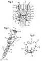
- Fig. 1
- shows a cross-sectional view of the bone anchoring device according to a first embodiment of the invention.
- Fig. 2
- shows an exploded view of the bone anchoring device according to
Fig. 1 . - Fig. 3
- shows a perspective view of the head of the bone anchoring element, which is part of the bone anchoring device according to
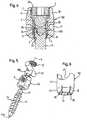
Fig. 1 . - Fig. 4
- shows a cross-sectional view of the bone anchoring device according to a second embodiment of the invention.
- Fig. 5
- shows an exploded view of the bone anchoring device according to
Fig. 4 . - Fig. 6
- shows a perspective view of the head of the bone anchoring element which is part of the bone anchoring device according to
Fig. 4 . - Fig. 7
- shows a cross-sectional view of the bone anchoring device according to a third embodiment.
- As shown in
Figs. 1 to 3 , the bone anchoring device comprises a receiving portion 1, which is substantially cylindrical and has afirst end 2 and asecond end 3 opposite to the first end. The two ends are perpendicular to a longitudinal axis 4. Coaxially with the longitudinal axis 4 abore 5 is provided which extends from thefirst end 2 to a predetermined distance from thesecond end 3. At thesecond end 3 anopening 6 is provided, the diameter of which is smaller than the diameter of thebore 5. Thecoaxial bore 5 tapers towards the opening 6 in form of a spherically-shaped section 7. - The receiving portion 1 further has a
U-shaped recess 8 which starts at thefirst end 2 and extends in the direction of thesecond end 3 to a predetermined distance from thesecond end 3. By means of the U-shaped recess, twofree legs first end 2. Adjacent to thefirst end 2 the receiving portion 1 comprises aninternal thread 11 at thelegs - The
bone anchoring element 13 comprises ashank 14 with abone thread 15 and ahead 16, which is formed as a separate part and which is connected to the shank in the assembled state shown inFig. 1 . Theshank 14 has a shank axis 14a and comprises acylindrical end portion 17 to be received in thehead 16 and atip 18 on the opposite end. The cylindrical end portion is provided with achamfer 17a to facilitate insertion into thehead 16. At its end surface, the end portion comprises arecess 12 for engagement with a screwing-in tool. - The
head 16 is substantially cylindrically shaped and comprises afirst end 19 and asecond end 20 opposite to the first end. As can be seen in particular inFig. 3 thehead 16 has afirst portion 21 adjacent to thefirst end 19, having a cylindrical outer surface. The diameter of thefirst portion 21 is just as large that thehead 16 can slide in thebore 5. Adjacent to thefirst portion 21, there is asecond portion 22, in which the outer surface of thehead 16 tapers towards thesecond end 20. In this embodiment, thesecond portion 22 has a spherical segment-shaped outer surface. The radius of the spherical segment corresponds to the radius of thespherical section 7 of the receiving part such that thehead 16 rests with itssecond portion 22 or a part thereof in the spherical portion of the receiving part 1. As can be seen in particular inFig. 1 , thehead 16 further comprises a firstcoaxial bore 23 extending from thesecond end 20 in direction to thefirst end 19. The diameter of the firstcoaxial bore 23 is just as large that theend portion 17 of the shank can be inserted into the bore from thesecond end 20. A secondcoaxial bore 24 is provided which extends from the end of the first bore 23 to thefirst end 19. The diameter of the secondcoaxial bore 24 is smaller than the diameter of the firstcoaxial bore 23 such that at the transition of the first bore 23 to the second bore 24 acircular abutment surface 25 is provided which forms a stop for theend portion 17 of the shank when theend portion 17 is inserted into the firstcoaxial bore 23 of thehead 16. - In the
second portion 22 of the head a plurality ofslits 26 are provided which are open towards thesecond end 20 and extend through thesecond portion 22 to a predetermined distance from thesecond end 20. In the embodiment shown inFig. 3 sixslits 26 are provided which are spaced equidistantly in a circumferential direction. However, fewer or more slits can be provided. At least one slit is required to render the second portion elastic to clamp theend portion 17 of the shank. Thesecond bore 24 allows for accessing therecess 12 provided at the end surface of theend portion 17 of the shank for screwing-in the shank into the bone with a screwing-in tool. - The
head 16 further comprises a cylindrical segment-shapedrecess 27 starting at thefirst end 19 and extending in the direction to thesecond end 20. The cylinder axis of therecess 27 is perpendicular to the longitudinal axis 4. The radius of therecess 27 corresponds to the radius of arod 28 to be received in therecess 27. The size of therecess 27 is such that when therod 28 is inserted, it protrudes over thefirst end 19. - The bone anchoring device further comprises an
inner screw 30, which can be screwed-in between thelegs rod 28 and to exert a pressure via therod 28 on thehead 16. Theinternal thread 11 and the cooperating thread of theinner screw 30 can have any known thread shape. A flat thread or a negative angle thread however, has the advantage that a splaying of thelegs - The length of the
head 16 is such that in an assembled state shown inFig. 1 thehead 16 encompasses theend portion 17 of the shank with the spherical segment-shapedsecond portion 22 and a part of thecylindrical portion 21. - The parts of the bone anchoring device described above are preferably made of a body compatible material, such as for example, titanium.
- In a first mode of operation, a
shank 14 of suitable length and with a desiredbone thread 15 is selected and connected with itsend portion 17 to thehead 16 by introducing it from thesecond end 20 of thehead 16 into thefirst bore 23 until the end surface abuts to theabutment surface 25. The introduction of theend portion 17 into thehead 16 from thesecond side 20 is facilitated by thechamfer 17a. Theend portion 17 is provisionally held in thehead 16 by means of friction. - Then, the
bone anchoring element 13 consisting of theshank 14 with the mountedhead 16 is introduced into the receiving portion 1 from thefirst end 2 with the threadedshank 14 being guided through theopening 6 of the receiving portion until thehead 16 rests against the edge of theopening 6. The head and the shank are rotated such that therecess 27 of the head is aligned with theU-shaped recess 8 of the receiving portion. In such a preassembled state which can be loosely held by crimp bores 31 shown inFig. 1 , the shank is screwed into the bone with a screwing-in tool which engages therecess 12 in theend portion 17 through thesecond bore 24 in the head. Theshank 14 can be fully screwed into the pre-drilled core hole without the necessity of alignment of the receiving portion during the screwing-in procedure. - When the shank is fully screwed-in, the receiving portion together with the head can be rotated around the longitudinal axis 4 by 360° to align it with respect to the
rod 28 to be inserted. After aligning the receiving portion 1 therod 28 is inserted until it rests in thecylindrical recess 27 of the head. Then theinner screw 30 is inserted and tightened until it presses onto therod 28 which itself presses thehead 16 against thespherical portion 7 of the receiving portion. By pressing thehead 16 against thespherical section 7 of the receiving portion thespherical portion 22 of the head is compressed due to theslits 26 and firmly clamps the shank. At the same time the head is pressed against thespherical portion 7 and locked relative to the receiving portion 1 in its rotational position. - In a second mode of operation, the threaded
shank 14 is first screwed into the bone or into a vertebra. Then, the receiving portion 1 together with the looselypreassembled head 16 is pressed onto theend portion 17 of the shank projecting out of the bone. Thereafter, the receiving portion 1 is aligned such as to be able to receive therod 28. Then theinner screw 30 is screwed-in to fix to the head and the rod. - With the bone anchoring device it is possible to use a
shank 14 with abone thread 15 having a larger thread pitch than conventional monoaxial bone screws. Also the use of multiple-threads for the bone thread is possible. Since the receiving portion can be rotated by 360° around the shaft axis, the shaft can be screwed-in to the maximum depth in the core hole. - It is further possible to use the receiving portion of conventional polyaxial bone screws together with the head and shank of this embodiment.
- In the second embodiment shown in
Figs. 4 to 6 , parts which are identical to the first embodiment are provided with the same reference signs as in the first embodiment. The second embodiment differs from the first embodiment in the shape of the section of the receiving portion against which the head rests and the shape of the head. The receivingportion 100 of the second embodiment has instead of the spherical segment-shaped section 7 aconically tapering section 70 adjacent to thesecond end 3. Correspondingly thehead 160 has asecond portion 221 with an outer surface which conically tapers towards thesecond end 20. The cone angle of thesecond portion 221 of the head corresponds to the cone angle of theportion 70 of the receiving portion. The cone angle is selected such that in a preassembled state the receivingportion 100 is still rotatable relative to thehead 160. - The modes of operation are identical to the first embodiment. Description thereof shall not be repeated.
- The bone anchoring device of the second embodiment has the advantage that the head having the conical outer surface is easier to manufacture.
- Modifications of the embodiments are possible. The diameter of the threaded portion of the
shank 14 can be smaller or larger than the diameter of theend portion 17. Theend portion 17 can have a conical shape such that the diameter increases towards the free end. The corresponding first bore 23 of the head can have a corresponding conical shape. In this case the diameter of thefirst bore 23 is slightly smaller than the diameter of the end portion. Theslits 26 allow an easy opening of thebore 23 and after inserting the end portion of the shank the end portion is slightly clamped. The cone angle can be selected such that a self locking occurs when the shank is inserted into the head. The head can have one or more slits which are open towards thefirst end 19. - In a further modification, the head is formed of a material providing elasticity, for example a suitable plastic material. In this case, the slits may be omitted.
- The receiving portion can be modified, too. The radius of the
spherical section 7 of the receiving portion of the first embodiment can be larger than the radius of the head, as long as the opening is small enough that the head cannot fall out. It is even possible to have a shape which is not spherical but rounded or otherwise tapered towards the opening. - The
head 16 can have a U-shaped recess instead of thecylindrical recess 27 in such a way that by the U-shaped recess two free legs are formed. The dimensions of the U-shaped recess are such that the legs project above the rod when the rod is inserted. In this case it is possible to separately fix thehead 16 via the inner screw without fixing the rod. To fix the rod, a separate inner screw is necessary. - The head also can have a flat free end surface.
- In the embodiments described the shank and the head are separate parts. However, it is also conceivable that the shank and the head are formed as a single piece bone anchoring element.
Fig. 7 shows a third embodiment which comprises a bone anchoring element with a shank and a head formed as a single piece. - Parts of this embodiment which are identical to the second or first embodiment have the same reference numerals as those of the second or first element. The receiving
portion 100 is shaped as the receving portion of the second embodiment shown inFig. 4 which has theconically tapering region 70 adjacent to thesecond end 3. Thebone anchoring element 130 comprises ashank 114 having a bone thread (not shown) and ahead 161 formed as a single piece. Thehead 161 has afirst portion 121 having a cylindrical outer surface and an adjacentsecond portion 122 having a conical outer surface tapering towards the shank. The diameter of the first portion is such that the head can slide in thebore 5 of the receivingportion 100. The cone angle of theconical portion 122 corresponds to that of theconical portion 70 of the receiving portion. Thefree end surface 123 of the head is flat and has arecess 12 for engagement with a screwing-in tool. The flat surface ensures that it is possible to align the receiving portion. - In use the
bone anchoring element 130 is first inserted into the receivingportion 100, then it is screwed into the bone. - When it is fully seated in the bone, the receiving portion is still rotatable with respect to the head and thus can be aligned to receive the rod. After inserting the
rod 28 theinner screw 30 is tightened and exerts pressure on therod 28 which exerts pressure on thehead 161. The head is pressed against theopening 6 of the receiving portion or against theconical section 70 and is locked in its rotational position. - Modifications are possible. The conical section of the receiving portion can have another shape. The head can have, for example, a sperical section instead of the conical section.
Claims (9)
- Bone anchoring device comprising
an anchoring element (13) comprising a shank (14) to be anchored in a bone or a vertebra and having a shank axis (14a), and a head (16; 160);
a receiving portion (1; 100) comprising a first end (2) and a second end (3) opposite to the first end (2), a longitudinal axis (4) passing through the two ends, a bore (5) coaxial with the longitudinal axis (4), said bore (5) having a smaller diameter adjacent to the second end (3) to form a first region (7; 70) for receiving a section (22; 221) of said head, and a U-shaped recess (8) starting at the first end (2) and extending in the direction of the second end (3) to receive a rod (28), by the U-shaped recess (8), two free legs (9, 10) are formed ending towards the first end (2);
an element (30) screwable between the legs (9, 10), which exerts pressure on said head (16; 160) to lock said head in the receiving portion;
wherein the receiving portion (1) and the anchoring element (13) are connected such that the longitudinal axis (4) of the receiving portion (1) and the shank axis (14a) have a fixed angle relative to each other and wherein the receiving portion (1) and the shank (14) are rotatable with respect to each other around the longitudinal axis (4) when the pressure is not exerted on the head and are locked in the rotational position when the pressure is exerted on the head; wherein
said shank (14) and said head (16; 160) are separate parts,
said head (16) has a portion (22, 221) which elastically clamps said shaft (14) when pressure is exerted on the head (16; 160) ; and
said head (16; 160) has a first end (19) and a second end (20) and a cylindrical recess (27) extending from the first end in the direction of the second end to receive a rod (28). - The bone anchoring element of claim 1, wherein said head (16; 160) has an exterior surface with a cylindrical portion (21).
- The bone anchoring element of one of claims 1 to 2wherein the head (16; 160) has a hollow interior portion (23) to receive the shank.
- The bone anchoring element of one of claims 1 to 3, wherein the head has a first end (19) and a second end (20) and a portion (22; 221) to clamp the shank tapers towards the second end (20).
- The bone anchoring element of claim 4, wherein the portion (22) to clamp the shank is spherically-shaped.
- The bone anchoring element of claim 4, wherein the portion (221) to clamp the shank is conically-shaped.
- The bone anchoring element of one of claims 4 to 6, wherein the portion (22; 221) to clamp the head comprises at least one slit (26).
- The bone anchoring element of one of claims 1 to 7, wherein said first region (7; 70) of the receiving portion (1) for receiving the head (16; 160) tapers towards the second end (3)
- The bone anchoring element of one of claims 1 to 8, wherein the longitudinal axis (4) of the receiving portion (1; 100) and the shank axis (14a) are coaxial.
Priority Applications (8)
| Application Number | Priority Date | Filing Date | Title |
|---|---|---|---|
| DE200560024795DE602005024795D1 (en) | 2005-08-03 | 2005-08-03 | Bone anchoring device |
| EP05016901AEP1749489B1 (en) | 2005-08-03 | 2005-08-03 | Bone anchoring device |
| ES05016901TES2356638T3 (en) | 2005-08-03 | 2005-08-03 | BONE ANCHORAGE DEVICE. |
| JP2006210982AJP5084195B2 (en) | 2005-08-03 | 2006-08-02 | Bone anchoring device |
| CN200610109135.7ACN1907240B (en) | 2005-08-03 | 2006-08-02 | Bone anchoring device |
| US11/498,931US8696712B2 (en) | 2005-08-03 | 2006-08-03 | Bone anchoring device |
| TW095128414ATWI423783B (en) | 2005-08-03 | 2006-08-03 | Bone anchoring device |
| US14/197,017US20140296920A1 (en) | 2005-08-03 | 2014-03-04 | Bone anchoring device |
Applications Claiming Priority (1)
| Application Number | Priority Date | Filing Date | Title |
|---|---|---|---|
| EP05016901AEP1749489B1 (en) | 2005-08-03 | 2005-08-03 | Bone anchoring device |
Publications (2)
| Publication Number | Publication Date |
|---|---|
| EP1749489A1 EP1749489A1 (en) | 2007-02-07 |
| EP1749489B1true EP1749489B1 (en) | 2010-11-17 |
Family
ID=35198046
Family Applications (1)
| Application Number | Title | Priority Date | Filing Date |
|---|---|---|---|
| EP05016901AExpired - LifetimeEP1749489B1 (en) | 2005-08-03 | 2005-08-03 | Bone anchoring device |
Country Status (3)
| Country | Link |
|---|---|
| EP (1) | EP1749489B1 (en) |
| DE (1) | DE602005024795D1 (en) |
| ES (1) | ES2356638T3 (en) |
Families Citing this family (4)
| Publication number | Priority date | Publication date | Assignee | Title |
|---|---|---|---|---|
| ES2348814T3 (en) | 2007-07-31 | 2010-12-15 | Biedermann Motech Gmbh | ANCHORAGE DEVICE Ã “SEO. |
| ES2378588T3 (en) | 2008-12-30 | 2012-04-16 | Biedermann Motech Gmbh | Receiving part for receiving a rod for coupling the rod in a bone anchoring element and bone anchoring device with such receiving part |
| ES2548580T3 (en) | 2009-02-20 | 2015-10-19 | Biedermann Technologies Gmbh & Co. Kg | Receiving part for housing a rod for coupling to a bone anchoring element and bone anchoring device that includes such receiving part |
| EP2764840B1 (en) | 2013-02-11 | 2017-05-03 | Biedermann Technologies GmbH & Co. KG | Coupling assembly for coupling a rod to a bone anchoring element and bone anchoring device with such a coupling assembly |
Citations (1)
| Publication number | Priority date | Publication date | Assignee | Title |
|---|---|---|---|---|
| WO2005122965A2 (en)* | 2004-06-09 | 2005-12-29 | Spinal Generations, Llc | Spinal fixation system |
Family Cites Families (6)
| Publication number | Priority date | Publication date | Assignee | Title |
|---|---|---|---|---|
| DE4330837A1 (en) | 1993-09-11 | 1995-03-16 | Michael Hahn | Pedicle screw and internal fixator |
| US5899904A (en) | 1998-10-19 | 1999-05-04 | Third Milennium Engineering, Llc | Compression locking vertebral body screw, staple, and rod assembly |
| US6626906B1 (en) | 2000-10-23 | 2003-09-30 | Sdgi Holdings, Inc. | Multi-planar adjustable connector |
| CN1268294C (en) | 2001-11-22 | 2006-08-09 | 库尔斯恩蒂斯股份公司 | Device for joining a longitudinal support with a bone fixation means |
| DE20207851U1 (en)* | 2002-05-21 | 2002-10-10 | Metz-Stavenhagen, Peter, Dr.med., 34537 Bad Wildungen | Anchoring element for fastening a rod of a device for setting up a human or animal spine to a vertebral bone |
| US8070785B2 (en)* | 2003-09-16 | 2011-12-06 | Spineco, Inc. | Bone anchor prosthesis and system |
- 2005
- 2005-08-03EPEP05016901Apatent/EP1749489B1/ennot_activeExpired - Lifetime
- 2005-08-03ESES05016901Tpatent/ES2356638T3/ennot_activeExpired - Lifetime
- 2005-08-03DEDE200560024795patent/DE602005024795D1/ennot_activeExpired - Lifetime
Patent Citations (1)
| Publication number | Priority date | Publication date | Assignee | Title |
|---|---|---|---|---|
| WO2005122965A2 (en)* | 2004-06-09 | 2005-12-29 | Spinal Generations, Llc | Spinal fixation system |
Also Published As
| Publication number | Publication date |
|---|---|
| DE602005024795D1 (en) | 2010-12-30 |
| ES2356638T3 (en) | 2011-04-11 |
| EP1749489A1 (en) | 2007-02-07 |
Similar Documents
| Publication | Publication Date | Title |
|---|---|---|
| US8696712B2 (en) | Bone anchoring device | |
| US20220096130A1 (en) | Receiving part for receiving a rod for coupling the rod to a bone anchoring element | |
| EP1741396B1 (en) | Bone anchoring device | |
| EP2191780B1 (en) | Receiving part for receiving a rod for coupling the rod to a bone anchoring element and a bone anchoring device with such a receiving part | |
| AU761056B2 (en) | Bone screw with axially two-part screw head | |
| US8784455B2 (en) | Bone anchoring device | |
| EP2526881B1 (en) | Receiving part for receiving a rod for coupling the rod to a bone anchoring element and bone anchoring device with such a receiving part | |
| US20120179211A1 (en) | Receiving part for receiving a rod for coupling the rod to a bone anchoring element and bone anchoring device with such a receiving part | |
| EP2668920B1 (en) | Polyaxial bone anchoring device | |
| EP1749489B1 (en) | Bone anchoring device | |
| KR101201526B1 (en) | Bone anchoring device |
Legal Events
| Date | Code | Title | Description |
|---|---|---|---|
| PUAI | Public reference made under article 153(3) epc to a published international application that has entered the european phase | Free format text:ORIGINAL CODE: 0009012 | |
| AK | Designated contracting states | Kind code of ref document:A1 Designated state(s):AT BE BG CH CY CZ DE DK EE ES FI FR GB GR HU IE IS IT LI LT LU LV MC NL PL PT RO SE SI SK TR | |
| AX | Request for extension of the european patent | Extension state:AL BA HR MK YU | |
| 17P | Request for examination filed | Effective date:20070807 | |
| 17Q | First examination report despatched | Effective date:20070907 | |
| AKX | Designation fees paid | Designated state(s):CH DE ES FR GB IT LI | |
| GRAP | Despatch of communication of intention to grant a patent | Free format text:ORIGINAL CODE: EPIDOSNIGR1 | |
| GRAS | Grant fee paid | Free format text:ORIGINAL CODE: EPIDOSNIGR3 | |
| GRAA | (expected) grant | Free format text:ORIGINAL CODE: 0009210 | |
| AK | Designated contracting states | Kind code of ref document:B1 Designated state(s):CH DE ES FR GB IT LI | |
| REG | Reference to a national code | Ref country code:GB Ref legal event code:FG4D | |
| REG | Reference to a national code | Ref country code:CH Ref legal event code:EP | |
| REF | Corresponds to: | Ref document number:602005024795 Country of ref document:DE Date of ref document:20101230 Kind code of ref document:P | |
| REG | Reference to a national code | Ref country code:CH Ref legal event code:NV Representative=s name:NOVAGRAAF INTERNATIONAL SA | |
| REG | Reference to a national code | Ref country code:ES Ref legal event code:FG2A Ref document number:2356638 Country of ref document:ES Kind code of ref document:T3 Effective date:20110411 | |
| REG | Reference to a national code | Ref country code:CH Ref legal event code:PFA Owner name:BIEDERMANN MOTECH GMBH Free format text:BIEDERMANN MOTECH GMBH#BERTHA-VON-SUTTNER-STRASSE 23#78054 VS-SCHWENNINGEN (DE) -TRANSFER TO- BIEDERMANN MOTECH GMBH#BERTHA-VON-SUTTNER-STRASSE 23#78054 VS-SCHWENNINGEN (DE) | |
| PLBE | No opposition filed within time limit | Free format text:ORIGINAL CODE: 0009261 | |
| STAA | Information on the status of an ep patent application or granted ep patent | Free format text:STATUS: NO OPPOSITION FILED WITHIN TIME LIMIT | |
| 26N | No opposition filed | Effective date:20110818 | |
| REG | Reference to a national code | Ref country code:DE Ref legal event code:R097 Ref document number:602005024795 Country of ref document:DE Effective date:20110818 | |
| REG | Reference to a national code | Ref country code:DE Ref legal event code:R082 Ref document number:602005024795 Country of ref document:DE Representative=s name:PRUEFER & PARTNER GBR, DE | |
| REG | Reference to a national code | Ref country code:DE Ref legal event code:R082 Ref document number:602005024795 Country of ref document:DE Representative=s name:PRUEFER & PARTNER GBR, DE Effective date:20121128 Ref country code:DE Ref legal event code:R081 Ref document number:602005024795 Country of ref document:DE Owner name:BIEDERMANN TECHNOLOGIES GMBH & CO. KG, DE Free format text:FORMER OWNER: BIEDERMANN MOTECH GMBH, 78054 VILLINGEN-SCHWENNINGEN, DE Effective date:20121128 Ref country code:DE Ref legal event code:R082 Ref document number:602005024795 Country of ref document:DE Representative=s name:PRUEFER & PARTNER MBB PATENTANWAELTE RECHTSANW, DE Effective date:20121128 | |
| REG | Reference to a national code | Ref country code:CH Ref legal event code:PUE Owner name:BIEDERMANN TECHNOLOGIES GMBH AND CO. KG, DE Free format text:FORMER OWNER: BIEDERMANN MOTECH GMBH AND CO. KG, DE Ref country code:CH Ref legal event code:PFA Owner name:BIEDERMANN MOTECH GMBH AND CO. KG, DE Free format text:FORMER OWNER: BIEDERMANN MOTECH GMBH, DE | |
| REG | Reference to a national code | Ref country code:ES Ref legal event code:PC2A Owner name:BIEDERMANN MOTECH GMBH & CO.KG. Effective date:20130205 Ref country code:CH Ref legal event code:PFA Owner name:BIEDERMANN MOTECH GMBH AND CO. KG, DE Free format text:FORMER OWNER: BIEDERMANN MOTECH GMBH, DE Ref country code:CH Ref legal event code:PUE Owner name:BIEDERMANN TECHNOLOGIES GMBH AND CO. KG, DE Free format text:FORMER OWNER: BIEDERMANN MOTECH GMBH AND CO. KG, DE | |
| REG | Reference to a national code | Ref country code:ES Ref legal event code:PC2A Owner name:BIEDERMANN TECHNOLOGIES GMBH & CO. KG Effective date:20130311 | |
| REG | Reference to a national code | Ref country code:GB Ref legal event code:732E Free format text:REGISTERED BETWEEN 20130307 AND 20130313 | |
| REG | Reference to a national code | Ref country code:FR Ref legal event code:TP Owner name:BIEDERMANN TECHNOLOGIES GMBH & CO.KG, DE Effective date:20130329 Ref country code:FR Ref legal event code:CD Owner name:BIEDERMANN TECHNOLOGIES GMBH & CO.KG, DE Effective date:20130329 | |
| REG | Reference to a national code | Ref country code:FR Ref legal event code:PLFP Year of fee payment:12 | |
| PGFP | Annual fee paid to national office [announced via postgrant information from national office to epo] | Ref country code:IT Payment date:20160823 Year of fee payment:12 Ref country code:DE Payment date:20160830 Year of fee payment:12 Ref country code:CH Payment date:20160824 Year of fee payment:12 Ref country code:GB Payment date:20160824 Year of fee payment:12 | |
| PGFP | Annual fee paid to national office [announced via postgrant information from national office to epo] | Ref country code:FR Payment date:20160825 Year of fee payment:12 | |
| PGFP | Annual fee paid to national office [announced via postgrant information from national office to epo] | Ref country code:ES Payment date:20160829 Year of fee payment:12 | |
| REG | Reference to a national code | Ref country code:DE Ref legal event code:R119 Ref document number:602005024795 Country of ref document:DE | |
| REG | Reference to a national code | Ref country code:CH Ref legal event code:PL | |
| GBPC | Gb: european patent ceased through non-payment of renewal fee | Effective date:20170803 | |
| PG25 | Lapsed in a contracting state [announced via postgrant information from national office to epo] | Ref country code:CH Free format text:LAPSE BECAUSE OF NON-PAYMENT OF DUE FEES Effective date:20170831 Ref country code:LI Free format text:LAPSE BECAUSE OF NON-PAYMENT OF DUE FEES Effective date:20170831 | |
| REG | Reference to a national code | Ref country code:FR Ref legal event code:ST Effective date:20180430 | |
| PG25 | Lapsed in a contracting state [announced via postgrant information from national office to epo] | Ref country code:GB Free format text:LAPSE BECAUSE OF NON-PAYMENT OF DUE FEES Effective date:20170803 Ref country code:DE Free format text:LAPSE BECAUSE OF NON-PAYMENT OF DUE FEES Effective date:20180301 | |
| PG25 | Lapsed in a contracting state [announced via postgrant information from national office to epo] | Ref country code:IT Free format text:LAPSE BECAUSE OF NON-PAYMENT OF DUE FEES Effective date:20170803 Ref country code:FR Free format text:LAPSE BECAUSE OF NON-PAYMENT OF DUE FEES Effective date:20170831 | |
| REG | Reference to a national code | Ref country code:ES Ref legal event code:FD2A Effective date:20181029 | |
| PG25 | Lapsed in a contracting state [announced via postgrant information from national office to epo] | Ref country code:ES Free format text:LAPSE BECAUSE OF NON-PAYMENT OF DUE FEES Effective date:20170804 |