EP1748515B1 - Antenna for portable terminal - Google Patents
Antenna for portable terminalDownload PDFInfo
- Publication number
- EP1748515B1 EP1748515B1EP06010302AEP06010302AEP1748515B1EP 1748515 B1EP1748515 B1EP 1748515B1EP 06010302 AEP06010302 AEP 06010302AEP 06010302 AEP06010302 AEP 06010302AEP 1748515 B1EP1748515 B1EP 1748515B1
- Authority
- EP
- European Patent Office
- Prior art keywords
- antenna
- sheet
- keypad
- keypad assembly
- assembly
- Prior art date
- Legal status (The legal status is an assumption and is not a legal conclusion. Google has not performed a legal analysis and makes no representation as to the accuracy of the status listed.)
- Ceased
Links
Images


Classifications
- H—ELECTRICITY
- H01—ELECTRIC ELEMENTS
- H01Q—ANTENNAS, i.e. RADIO AERIALS
- H01Q1/00—Details of, or arrangements associated with, antennas
- H01Q1/12—Supports; Mounting means
- H01Q1/22—Supports; Mounting means by structural association with other equipment or articles
- H01Q1/24—Supports; Mounting means by structural association with other equipment or articles with receiving set
- H01Q1/241—Supports; Mounting means by structural association with other equipment or articles with receiving set used in mobile communications, e.g. GSM
- H01Q1/242—Supports; Mounting means by structural association with other equipment or articles with receiving set used in mobile communications, e.g. GSM specially adapted for hand-held use
- H01Q1/243—Supports; Mounting means by structural association with other equipment or articles with receiving set used in mobile communications, e.g. GSM specially adapted for hand-held use with built-in antennas
- H—ELECTRICITY
- H01—ELECTRIC ELEMENTS
- H01Q—ANTENNAS, i.e. RADIO AERIALS
- H01Q1/00—Details of, or arrangements associated with, antennas
- H01Q1/36—Structural form of radiating elements, e.g. cone, spiral, umbrella; Particular materials used therewith
- H01Q1/38—Structural form of radiating elements, e.g. cone, spiral, umbrella; Particular materials used therewith formed by a conductive layer on an insulating support
- H—ELECTRICITY
- H04—ELECTRIC COMMUNICATION TECHNIQUE
- H04M—TELEPHONIC COMMUNICATION
- H04M1/00—Substation equipment, e.g. for use by subscribers
- H04M1/02—Constructional features of telephone sets
- H04M1/23—Construction or mounting of dials or of equivalent devices; Means for facilitating the use thereof
Definitions
- the present inventionrelates to an antenna for a portable terminal, and more particularly, to an antenna for a portable terminal, in which an antenna occupying a relatively large area can be efficiently installed without increasing the volume of the terminal.
- terminal manufacturershave made an effort to produce slim and lightweight terminals having various functions so as to satisfy users' demands. For example, the user can take a photograph using a small-sized camera module mounted on the terminal and can listen to music using an MP3 player mounted on the terminal. These functions cause the terminal to increase in volume due to the installation of the corresponding devices. Terminal manufacturers have made many efforts to solve these problems and implement various additional functions.
- NFCnear field communication
- terminals having a 2.4-GHz Bluetooth TM function for NFChave been introduced.
- the Bluetooth TM functioninclude data communication between terminals, and wireless communication between an ear microphone and a terminal.
- a Bluetooth TM chipTo perform the above-described Bluetooth TM function, a Bluetooth TM chip must be mounted on the terminal and a radiator must also be installed in the terminal.
- the Bluetooth TM radiatormust be separated from an RF radiator used for data transmission and reception.
- the Bluetooth TM radiatoris mounted on an RF board in a Surface Mount Device (SMD) type.
- SMDSurface Mount Device
- a chip antenna and a plate type monopole antennahave been widely used as the Bluetooth TM radiator.
- terminals having the NFC function for electronic payment, Peer-to-Peer (P2P) communication, and a card reader functionhave been introduced.
- the above-described NFC functionmust use separate devices, and a separate antenna (other than an antenna radiator for communication) is used for an RF communication with a payment device.
- ICsIntegrated Circuits
- OSCsOscillators
- a low-frequency (about 13.56 MHz) antenna radiator for NFCis required. Since the low-frequency antenna radiator is bulky (about 30mmx50 mm), it has been generally built in a battery pack of the terminal.
- the NFC antennais bulky, it is installed over an entire rear surface of the battery pack that is a power supply of the terminal. Therefore, an expensive ferrite layer must be used for avoiding the interference between the antenna and the conductive battery cell.
- US 6,016,126relates to a non-protruding dual-band antenna in a communication device having a dual-band antenna and comprises a keypad installed on a board having a contact pad and a dual-band antenna disposed between the keypad and a housing installed on the keypad.
- EP 1 450 385relates to a keypad of a portable wireless terminal and a fabrication method thereof. It includes a board having buttons, a case frame, a silicon sheet and a metal dome.
- US 5,710,987relates to a receiver having a concealed external antenna and to a radio telephone/pager unit where a pager and a radio telephone are formed as one device. Further, an installation location of a pager antenna is disclosed as well as a method for installing a pager antenna in a display, a keypad and a speaker.
- US 5,561,437relates to a fold-over dipole antenna and installed antenna arms positioned in a housing and a flap.
- an antenna for a portable terminalcapable of installing added functions without increasing the size of the terminal.
- an antenna for a portable terminalin which the antenna is interposed in a space where existing components are installed, thus contributing to the slim profile and lightweight without increasing the volume of the terminal.
- an antenna for a portable terminalwhich does not need an interference avoiding element due to an expensive NFC antenna radiator and its installation.
- an antenna for a portable terminalincluding a keypad assembly having a plurality of key buttons; a main antenna unit; and another antenna unit where a predetermined pattern is formed, with the other antenna unit being interposed between components of the keypad assembly.
- a pad assembly for a portable terminalincluding a main board installed inside the terminal, the main board including metal domes spaced apart from one another by a predetermined distance; a keypad rubber formed on the main board, the keypad rubber including contact protrusions corresponding to the metal domes; an antenna sheet formed on the keypad rubber and in which a conductive pattern with a predetermined size and a predetermined shape is formed; and a keypad sheet, formed on the antenna sheet and in which the key buttons corresponding to the respective contact protrusions are installed or formed.
- FIG. 1is a perspective view of a portable terminal having a keypad assembly according to the present invention
- FIG. 2is an exploded perspective view of the keypad assembly illustrated in FIG. 1 ;
- FIG. 3is a sectional view of the keypad assembly illustrated in FIG. 2 ;
- FIG. 4is a perspective view of an antenna sheet according to another embodiment of the present invention.
- FIG. 5is a sectional view of a keypad assembly having the antenna sheet illustrated in FIG. 4 ;
- FIGs. 6 and 7are views of antenna sheets according to further embodiments of the present invention.
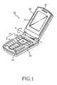
- FIG. 1is a perspective view of a portable terminal 10 having a keypad assembly according to the present invention. Specifically, a folder type terminal is illustrated in FIG. 1 .
- the present inventioncan be applied to various types of terminals including a keypad assembly with a plurality of key buttons that are manipulated by users.
- the folder type terminal 10includes a main body 20 and a folder 30.
- the folderis rotatable around a rotational shaft A and is opened from the main body at a predetermined angle.
- the main body 20includes a keypad assembly 21 having a plurality of key buttons.
- the keypad assembly 21may include a 3x4 numeric keypad assembly 21 a and a navigation keypad assembly 22b.
- the 3x4 numeric keypad assembly 21acan be used to make a phone call by pressing the numeric keys.
- the navigation keypad assembly 21 bcan be manipulated to use a variety of additional features, such as a camera module, a music listening device, and the Internet.
- a microphone 24may be installed below the keypad assembly 21 to send a voice to the other calling party.
- a display unit 31may be installed in the front surface of the folder 30.
- a high-definition color LCD modulemay be used for the display unit 31.
- a speaker 32may be installed above the display unit 31 to output a voice of the other calling party.
- a main antennamay be installed in a suitable location of the terminal.
- a built-in antenna mounted on a rear surface of a main board of the main body of the present inventionthe present invention is not limited to the built-in antenna.
- the present inventionrelates to a separate antenna other than a built-in antenna or a retractable antenna protruding from the terminal.
- the antenna of the present inventionis provided in a thin sheet type and is interposed between components of the keypad assembly 21. Therefore, the interference of the antenna can be avoided.
- the antenna of the present inventionis electrically connected to a feeder part of a Near Field Communication (NFC) module of the main board.
- NFCNear Field Communication
- FIG. 2is an exploded perspective view of the keypad assembly 21 according to the present invention.
- FIG. 3is a sectional view of the keypad assembly illustrated in FIG. 2 .
- components of a 3x4 numeric keypad assembly and an antenna sheetare illustrated in FIGS. 2 and 3 , the present invention is not limited to this configuration.
- an antenna sheetmay be expanded so that it can be shared by the numeric keypad assembly and the navigation keypad assembly.
- the keypad assembly 21 of the present inventionincludes a main board 211 installed in the main body of the terminal.
- a keypad rubber 213, an antenna sheet 214, and a keypad sheet 216are sequentially stacked on the main board 211.
- the keypad sheet 216has a plurality of key buttons 217.
- the main board 211includes metal domes 212 installed at positions corresponding to the key buttons 217 of the keypad sheet 216.
- the metal domes 212serve as a switching element to recognize button manipulation of the terminal by electrically connecting carbon contact points, spaced apart from one another in the main board 211.
- the keypad rubber 213is preferably formed of silicon material, and contact protrusions 213-1 are formed at positions corresponding to the metal domes 212.
- a space Sis defined around the contact protrusions 213-1 in a skirt shape, such that the metal domes 212 can be smoothly pressurized by the protrusions 213-1.
- a conductive pattern 215 with a predetermined shapemay be formed in the antenna sheet 214.
- NFCNear Field Communication
- FIG. 2a Near Field Communication (NFC) antenna pattern is illustrated in FIG. 2 , the present invention is not limited thereto.
- existing BluetoothTM antenna patterns or wireless local access network (WLAN) antenna radiatorsmay be formed individually or may be integrally formed spaced apart from one another by a predetermined distance.
- the keypad sheet 216may be formed of silicon and a plurality of plastic key buttons 217 may be attached to the key sheet 216. Also, the keypad rubber 213, the antenna sheet 214, the keypad sheet 216, and the keypad buttons 217 may be bonded together by an adhesive.
- the corresponding contact protrusions 213-1 of the keypad rubber 213are pressed through the antenna sheet 214.
- the contact protrusions 213-1pressurize the metal domes 212 on the main board 211 and therefore the corresponding carbon contact points of the main board 211 are electrically connected by the metal domes 212.
- the antenna sheet 214must have good flexibility. Further, due to the keypad rubber 213 formed by an insulating material, the antenna sheet 214 of the present invention is naturally spaced apart from a conductor such as a ground portion of the main board 211. Thus, it is unnecessary to install a separate insulator for avoiding the interference.
- FPCflexible printed circuit
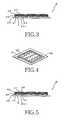
- FIG. 4is a perspective view of an antenna sheet according to another embodiment of the present invention.
- FIG. 5is a sectional view of a keypad assembly having the antenna sheet illustrated in FIG. 4 .
- the antenna sheetmay have penetration holes 222 through which the corresponding contact protrusions can pass.
- the NFC antenna radiator 221occupies a relatively large area, it may be formed to bypass the holes 222. Accordingly, as illustrated in FIG. 5 , a lower portion of the keypad sheet 216 passes through the penetration holes 222 of the antenna sheet 220 and contacts an upper portion of the corresponding contact protrusion 213-1 of the keypad rubber 213. Therefore, when pressing the key buttons 217, the user can feel a more flexible click of key buttons.
- FIGS. 6 and 7are views of antenna sheets according to further embodiments of the present invention.
- a pattern 253may partially pass through a numeric key part 252 and a navigation key part 251.
- the pattern 253can be used for an NFC antenna radiator requiring a relatively large area.
- a relatively small pattern 263is formed in the left side of the numeric key part 262, except the navigation key part 261.
- the pattern 263may be suitable for BluetoothTM antenna radiator or Wireless Local Area Network (WLAN) antenna radiator.
- the NFC antenna of the present inventionis interposed between components of the key button assembly in a sheet type. Consequently, a separate installation space for the antenna radiator is not required in the main board, resulting in volume reduction of the terminal. Also, since an installation area corresponding to the total area of the keypad assembly is available, two or more antennas with different bands can be installed.
Landscapes
- Engineering & Computer Science (AREA)
- Computer Networks & Wireless Communication (AREA)
- Signal Processing (AREA)
- Telephone Set Structure (AREA)
- Push-Button Switches (AREA)
Description
- The present invention relates to an antenna for a portable terminal, and more particularly, to an antenna for a portable terminal, in which an antenna occupying a relatively large area can be efficiently installed without increasing the volume of the terminal.
- With the rapid spread of portable terminals, terminal manufacturers have made an effort to produce slim and lightweight terminals having various functions so as to satisfy users' demands. For example, the user can take a photograph using a small-sized camera module mounted on the terminal and can listen to music using an MP3 player mounted on the terminal. These functions cause the terminal to increase in volume due to the installation of the corresponding devices. Terminal manufacturers have made many efforts to solve these problems and implement various additional functions.
- Among the additional functions of the terminal, a near field communication (NFC) technology has become commercialized. Recently, terminals having a 2.4-GHz Bluetooth™ function for NFC have been introduced. Examples of the Bluetooth™ function include data communication between terminals, and wireless communication between an ear microphone and a terminal. To perform the above-described Bluetooth™ function, a Bluetooth™ chip must be mounted on the terminal and a radiator must also be installed in the terminal.
- The Bluetooth™ radiator must be separated from an RF radiator used for data transmission and reception. For example, the Bluetooth™ radiator is mounted on an RF board in a Surface Mount Device (SMD) type. A chip antenna and a plate type monopole antenna have been widely used as the Bluetooth™ radiator.
- Also, terminals having the NFC function for electronic payment, Peer-to-Peer (P2P) communication, and a card reader function have been introduced. The above-described NFC function must use separate devices, and a separate antenna (other than an antenna radiator for communication) is used for an RF communication with a payment device. To use the above-described NFC function, it is necessary to mount smart Integrated Circuits (ICs), Oscillators (OSCs), and other passive elements on a main board of the terminal. Also, a low-frequency (about 13.56 MHz) antenna radiator for NFC is required. Since the low-frequency antenna radiator is bulky (about 30mmx50 mm), it has been generally built in a battery pack of the terminal. In addition, since the NFC antenna is bulky, it is installed over an entire rear surface of the battery pack that is a power supply of the terminal. Therefore, an expensive ferrite layer must be used for avoiding the interference between the antenna and the conductive battery cell.
- Therefore a separate antenna in addition to an existing antenna for communication must be installed in the Bluetooth™ antenna or NFC antenna radiator, thus increasing the size of the terminal. Consequently, the conventional antenna does not satisfy the trend toward slim profile, lightweight and multi-function portable terminal.
US 6,016,126 relates to a non-protruding dual-band antenna in a communication device having a dual-band antenna and comprises a keypad installed on a board having a contact pad and a dual-band antenna disposed between the keypad and a housing installed on the keypad.EP 1 450 385US 5,710,987 relates to a receiver having a concealed external antenna and to a radio telephone/pager unit where a pager and a radio telephone are formed as one device. Further, an installation location of a pager antenna is disclosed as well as a method for installing a pager antenna in a display, a keypad and a speaker.US 5,561,437 relates to a fold-over dipole antenna and installed antenna arms positioned in a housing and a flap.- It is the object of the present invention to provide an antenna for a portable terminal, capable of installing an NFC antenna without any separate installation space.
- This object is solved by the subject matter of the independent claims.
- Preferred embodiments are defined in the dependent claims.
- Also, according to an aspect of the present invention, there is provided an antenna for a portable terminal, capable of installing added functions without increasing the size of the terminal.
- In addition, according to a further aspect of the present invention, there is provided an antenna for a portable terminal, in which the antenna is interposed in a space where existing components are installed, thus contributing to the slim profile and lightweight without increasing the volume of the terminal.
- Further, according to another aspect of the present invention, there is provided an antenna for a portable terminal, which does not need an interference avoiding element due to an expensive NFC antenna radiator and its installation.
- According to an aspect of the present invention, there is provided an antenna for a portable terminal including a keypad assembly having a plurality of key buttons; a main antenna unit; and another antenna unit where a predetermined pattern is formed, with the other antenna unit being interposed between components of the keypad assembly.
- According to another aspect of the present invention, there is provided a pad assembly for a portable terminal, including a main board installed inside the terminal, the main board including metal domes spaced apart from one another by a predetermined distance; a keypad rubber formed on the main board, the keypad rubber including contact protrusions corresponding to the metal domes; an antenna sheet formed on the keypad rubber and in which a conductive pattern with a predetermined size and a predetermined shape is formed; and a keypad sheet, formed on the antenna sheet and in which the key buttons corresponding to the respective contact protrusions are installed or formed.
- The accompanying drawings, which are included to provide a further understanding of the invention and are incorporated in and constitute a part of this application, illustrate embodiment(s) of the invention and together with the description serve to explain the principle of the invention. In the drawings:
FIG. 1 is a perspective view of a portable terminal having a keypad assembly according to the present invention;FIG. 2 is an exploded perspective view of the keypad assembly illustrated inFIG. 1 ;FIG. 3 is a sectional view of the keypad assembly illustrated inFIG. 2 ;FIG. 4 is a perspective view of an antenna sheet according to another embodiment of the present invention;FIG. 5 is a sectional view of a keypad assembly having the antenna sheet illustrated inFIG. 4 ; andFIGs. 6 and 7 are views of antenna sheets according to further embodiments of the present invention.- Reference will now be made in detail to the preferred embodiments of the present invention, examples of which are illustrated in the accompanying drawings. A detail description of well-known features will be omitted for conciseness.
FIG. 1 is a perspective view of aportable terminal 10 having a keypad assembly according to the present invention. Specifically, a folder type terminal is illustrated inFIG. 1 . The present invention can be applied to various types of terminals including a keypad assembly with a plurality of key buttons that are manipulated by users.- Referring to
FIG. 1 , thefolder type terminal 10 includes amain body 20 and afolder 30. The folder is rotatable around a rotational shaft A and is opened from the main body at a predetermined angle. Themain body 20 includes akeypad assembly 21 having a plurality of key buttons. Thekeypad assembly 21 may include a 3x4numeric keypad assembly 21 a and a navigation keypad assembly 22b. The 3x4numeric keypad assembly 21a can be used to make a phone call by pressing the numeric keys. Thenavigation keypad assembly 21 b can be manipulated to use a variety of additional features, such as a camera module, a music listening device, and the Internet. Amicrophone 24 may be installed below thekeypad assembly 21 to send a voice to the other calling party. - A
display unit 31 may be installed in the front surface of thefolder 30. A high-definition color LCD module may be used for thedisplay unit 31. Also, aspeaker 32 may be installed above thedisplay unit 31 to output a voice of the other calling party. - Although not shown in
FIG. 1 , a main antenna may be installed in a suitable location of the terminal. Although a built-in antenna mounted on a rear surface of a main board of the main body of the present invention, the present invention is not limited to the built-in antenna. The present invention relates to a separate antenna other than a built-in antenna or a retractable antenna protruding from the terminal. In addition, the antenna of the present invention is provided in a thin sheet type and is interposed between components of thekeypad assembly 21. Therefore, the interference of the antenna can be avoided. Moreover, the antenna of the present invention is electrically connected to a feeder part of a Near Field Communication (NFC) module of the main board. FIG. 2 is an exploded perspective view of thekeypad assembly 21 according to the present invention.FIG. 3 is a sectional view of the keypad assembly illustrated inFIG. 2 . Although components of a 3x4 numeric keypad assembly and an antenna sheet are illustrated inFIGS. 2 and3 , the present invention is not limited to this configuration. In the case of a keypad assembly in which a 3x4 numeric keypad assembly and a navigation keypad assembly are integrally formed, an antenna sheet may be expanded so that it can be shared by the numeric keypad assembly and the navigation keypad assembly.- The
keypad assembly 21 of the present invention includes amain board 211 installed in the main body of the terminal. In addition, akeypad rubber 213, anantenna sheet 214, and akeypad sheet 216 are sequentially stacked on themain board 211. Thekeypad sheet 216 has a plurality ofkey buttons 217. - The
main board 211 includesmetal domes 212 installed at positions corresponding to thekey buttons 217 of thekeypad sheet 216. The metal domes 212 serve as a switching element to recognize button manipulation of the terminal by electrically connecting carbon contact points, spaced apart from one another in themain board 211. - The
keypad rubber 213 is preferably formed of silicon material, and contact protrusions 213-1 are formed at positions corresponding to the metal domes 212. A space S is defined around the contact protrusions 213-1 in a skirt shape, such that themetal domes 212 can be smoothly pressurized by the protrusions 213-1. - A
conductive pattern 215 with a predetermined shape may be formed in theantenna sheet 214. Although a Near Field Communication (NFC) antenna pattern is illustrated inFIG. 2 , the present invention is not limited thereto. For example, existing Bluetooth™ antenna patterns or wireless local access network (WLAN) antenna radiators may be formed individually or may be integrally formed spaced apart from one another by a predetermined distance. - The
keypad sheet 216 may be formed of silicon and a plurality of plastickey buttons 217 may be attached to thekey sheet 216. Also, thekeypad rubber 213, theantenna sheet 214, thekeypad sheet 216, and thekeypad buttons 217 may be bonded together by an adhesive. - Accordingly, as illustrated in
FIG. 3 , when the user presses thekey buttons 217, the corresponding contact protrusions 213-1 of thekeypad rubber 213 are pressed through theantenna sheet 214. The contact protrusions 213-1 pressurize themetal domes 212 on themain board 211 and therefore the corresponding carbon contact points of themain board 211 are electrically connected by the metal domes 212. - Under this arrangement, patterns may be formed on the
antenna sheet 214 in a shape of an existing flexible printed circuit (FPC), or conductive patterns may be formed on a polyimide dielectric. Therefore, theantenna sheet 214 must have good flexibility. Further, due to thekeypad rubber 213 formed by an insulating material, theantenna sheet 214 of the present invention is naturally spaced apart from a conductor such as a ground portion of themain board 211. Thus, it is unnecessary to install a separate insulator for avoiding the interference. FIG. 4 is a perspective view of an antenna sheet according to another embodiment of the present invention.FIG. 5 is a sectional view of a keypad assembly having the antenna sheet illustrated inFIG. 4 . The antenna sheet may havepenetration holes 222 through which the corresponding contact protrusions can pass. Generally, since theNFC antenna radiator 221 occupies a relatively large area, it may be formed to bypass theholes 222. Accordingly, as illustrated inFIG. 5 , a lower portion of thekeypad sheet 216 passes through the penetration holes 222 of theantenna sheet 220 and contacts an upper portion of the corresponding contact protrusion 213-1 of thekeypad rubber 213. Therefore, when pressing thekey buttons 217, the user can feel a more flexible click of key buttons.FIGS. 6 and 7 are views of antenna sheets according to further embodiments of the present invention. Referring toFIG. 6 , since penetration holes are not formed in theantenna sheet 25, apattern 253 may partially pass through a numerickey part 252 and a navigationkey part 251. In this case, thepattern 253 can be used for an NFC antenna radiator requiring a relatively large area.- Referring to
FIG. 7 , a relativelysmall pattern 263 is formed in the left side of the numerickey part 262, except the navigationkey part 261. In this case, thepattern 263 may be suitable for Bluetooth™ antenna radiator or Wireless Local Area Network (WLAN) antenna radiator. - The NFC antenna of the present invention is interposed between components of the key button assembly in a sheet type. Consequently, a separate installation space for the antenna radiator is not required in the main board, resulting in volume reduction of the terminal. Also, since an installation area corresponding to the total area of the keypad assembly is available, two or more antennas with different bands can be installed.
Claims (17)
- An antenna for a portable terminal comprising:a keypad assembly (21) having a plurality of components;a main antenna unit; anda second antenna unit (215),characterized in thatthe keypad assembly comprises:a main board (211) installed inside the terminal, the main board including metal domes (212) spaced apart from one another by a predetermined distance;a keypad rubber (213) formed on the main board, the keypad rubber including contact protrusions (213-1) corresponding to the metal domes; anda keypad sheet (216) formed on the keypad rubber and in which the key buttons (217) corresponding to the respective contact protrusions are installed or formed, the second antenna (215) unit being interposed between the keypad rubber and the keypad sheet in a sheet type.
- The antenna of claim 1, wherein an antenna sheet (214) and the keypad sheet, sequentially formed on the keypad rubber in the main board, are bonded together.
- The antenna of claim 2, wherein the antenna sheet is a flexible printed circuit, FPC, sheet or a polyimide sheet where a conductive pattern (215) with a predetermined shape is formed at a predetermined position.
- The antenna of claim 3, wherein the pattern formed in the antenna sheet bypasses positions corresponding to the metal domes.
- The antenna of claim 3, wherein the pattern is formed in the antenna sheet regardless of positions corresponding to the metal domes.
- The antenna of claim 4, wherein the antenna sheet includes penetration holes at the positions corresponding to the metal domes, thereby reinforcing a button operation characteristic.
- The antenna of one of claims 2 to 6, wherein the keypad assembly includes a 3x4 numeric keypad assembly (21 a) and a navigation keypad assembly (21 b), and the antenna sheet is installed over at least one of a part and a whole of at least one of the 3x4 numeric keypad assembly and the navigation keypad assembly.
- The antenna of claim 7, wherein the pattern formed in the antenna sheet has a shape of a Near Field Communication, NFC, antenna radiator with a relatively large size compared to the size of the antenna sheet.
- The antenna of claim 8, wherein the pattern formed in the antenna sheet is at least one of an NFC antenna radiator, a Btuetooth™ antenna radiator, and a WLAN antenna radiator, which are spaced apart by a predetermined distance.
- A keypad assembly (21) for a portable terminal, comprising:a main board (211) installed inside the terminal, the main board including metal domes (212) spaced apart from one another by a predetermined distance;a keypad rubber (213) formed on the main board, the keypad rubber including contact protrusions (213-1) corresponding to the metal domes;an antenna sheet (214) formed on the keypad rubber and in which a conductive pattern (215) with a predetermined size and a predetermined shape is formed; anda keypad sheet (216) formed on the antenna sheet and in which the key buttons (217) corresponding to the respective contact protrusions are at least one of installed and formed on the keypad sheet.
- The keypad assembly of claim 10, wherein the pattern formed in the antenna sheet bypasses positions corresponding to the metal domes.
- The keypad assembly of claim 10, wherein the pattern is formed in the antenna sheet not considering positions corresponding to the metal domes.
- The keypad assembly of claim 11, wherein the antenna sheet includes penetration holes at the positions corresponding to the metal domes, thereby reinforcing a button operation characteristic.
- The keypad assembly of one of claims 10 to 13, including a 3x4 numeric keypad assembly (21 a) and a navigation keypad assembly (21 b), wherein the antenna sheet is installed over at least one of a part and whole of at least one of the 3x4 numeric keypad assembly and the navigation keypad assembly.
- The keypad assembly of claim 14, wherein the pattern formed in the antenna sheet has a shape of a Near Field Communication, NFC, antenna radiator with a relatively large size.
- The keypad assembly of claim 15, wherein the pattern formed in the antenna sheet is at least one of an Near Field Communication, NFC, antenna radiator, a Bluetooth™ antenna radiator, and a WLAN antenna radiator, which are spaced apart by a predetermined distance.
- A portable terminal, comprising:a keypad assembly as set out in claim 10.
Applications Claiming Priority (1)
| Application Number | Priority Date | Filing Date | Title |
|---|---|---|---|
| KR1020050067609AKR100733813B1 (en) | 2005-07-26 | 2005-07-26 | Antenna device of portable wireless terminal |
Publications (2)
| Publication Number | Publication Date |
|---|---|
| EP1748515A1 EP1748515A1 (en) | 2007-01-31 |
| EP1748515B1true EP1748515B1 (en) | 2008-09-10 |
Family
ID=36968925
Family Applications (1)
| Application Number | Title | Priority Date | Filing Date |
|---|---|---|---|
| EP06010302ACeasedEP1748515B1 (en) | 2005-07-26 | 2006-05-18 | Antenna for portable terminal |
Country Status (5)
| Country | Link |
|---|---|
| US (1) | US7388547B2 (en) |
| EP (1) | EP1748515B1 (en) |
| KR (1) | KR100733813B1 (en) |
| CN (1) | CN1905272B (en) |
| DE (1) | DE602006002683D1 (en) |
Cited By (1)
| Publication number | Priority date | Publication date | Assignee | Title |
|---|---|---|---|---|
| US8519895B2 (en) | 2010-02-05 | 2013-08-27 | Nokia Corporation | Keys and keylines used for antenna purposes |
Families Citing this family (22)
| Publication number | Priority date | Publication date | Assignee | Title |
|---|---|---|---|---|
| JP4896806B2 (en)* | 2007-04-26 | 2012-03-14 | 京セラ株式会社 | Communication equipment |
| CN101453048B (en)* | 2007-11-30 | 2013-03-27 | 李伟业 | Antenna assembly construction for radio products |
| US20090170559A1 (en)* | 2007-12-27 | 2009-07-02 | Simon Phillips | Mobile telephone with two antennas for use in contactless payments |
| US8212735B2 (en) | 2009-06-05 | 2012-07-03 | Nokia Corporation | Near field communication |
| KR101052115B1 (en)* | 2009-06-10 | 2011-07-26 | 엘지이노텍 주식회사 | NFC Antenna Using Double Resonance |
| US9008574B2 (en)* | 2009-09-14 | 2015-04-14 | Qualcomm Incorporated | Focused antenna, multi-purpose antenna, and methods related thereto |
| JP5758648B2 (en)* | 2010-02-24 | 2015-08-05 | 京セラ株式会社 | Mobile device |
| US8803739B2 (en)* | 2010-03-03 | 2014-08-12 | Tyco Electronics Services Gmbh | Multi-functional CRLH antenna device |
| CN101764280A (en)* | 2010-03-16 | 2010-06-30 | 中兴通讯股份有限公司 | Frequency modulation antenna and realization method and mobile terminal thereof |
| CN102419633B (en)* | 2010-09-27 | 2014-01-08 | 光宝电子(广州)有限公司 | Keyboard structure with antenna function |
| KR101678222B1 (en)* | 2010-09-30 | 2016-11-21 | 삼성전자주식회사 | A portable terminal having keypad |
| DE102010061351A1 (en) | 2010-12-20 | 2012-06-21 | Huf Hülsbeck & Fürst Gmbh & Co. Kg | Compact, NFC communication option having ID transmitter of a motor vehicle access system |
| KR101859575B1 (en)* | 2012-03-21 | 2018-05-18 | 삼성전자 주식회사 | Antenna device for near field wireless communication and electric device having the same |
| US8929810B2 (en) | 2012-04-23 | 2015-01-06 | Qualcomm Incorporated | Methods and apparatus for improving NFC connection through device positioning |
| EP2693722B1 (en)* | 2012-07-30 | 2017-01-04 | BlackBerry Limited | Hybrid keypad apparatus |
| US8847092B2 (en) | 2012-07-30 | 2014-09-30 | Blackberry Limited | Hybrid keypad apparatus |
| CN103094684B (en)* | 2013-02-04 | 2016-04-20 | 上海安费诺永亿通讯电子有限公司 | A kind of water proof and dust proof antenna of FPC form |
| US9274564B2 (en)* | 2013-11-28 | 2016-03-01 | Google Inc. | Antenna in or below keyboard |
| KR102152694B1 (en) | 2014-04-29 | 2020-09-07 | 엘지이노텍 주식회사 | Case apparatus |
| KR102342852B1 (en) | 2015-06-16 | 2021-12-23 | 삼성전자주식회사 | Wireless communication module and portable terminal including the same |
| FR3042315B1 (en)* | 2015-10-12 | 2018-03-23 | Ingenico Group | COMMUNICATION ANTENNA FOR NON-CONTACT PAYMENT TERMINAL |
| GB2551734A (en)* | 2016-06-28 | 2018-01-03 | Naim Audio Ltd | An Antenna configuration for an electronic device |
Family Cites Families (9)
| Publication number | Priority date | Publication date | Assignee | Title |
|---|---|---|---|---|
| US4328399A (en)* | 1979-02-05 | 1982-05-04 | Northern Telecom Limited | Pushbutton switch assembly for telecommunications and other input |
| SG64869A1 (en)* | 1993-02-25 | 1999-05-25 | Motorola Inc | Receiver having concealed external antenna |
| US5561437A (en)* | 1994-09-15 | 1996-10-01 | Motorola, Inc. | Two position fold-over dipole antenna |
| US6016126A (en)* | 1998-05-29 | 2000-01-18 | Ericsson Inc. | Non-protruding dual-band antenna for communications device |
| KR100472429B1 (en)* | 2002-10-18 | 2005-03-10 | 삼성전자주식회사 | Key pad assembly for portable radiotelephone and controlling method thereof |
| KR100493073B1 (en)* | 2002-12-06 | 2005-06-02 | 삼성전자주식회사 | Antenna apparatus for portable wireless terminal |
| KR100539780B1 (en)* | 2003-02-20 | 2006-01-10 | 엘지전자 주식회사 | Keypad of portable wireless terminal and manufacturing method thereof |
| US20050222961A1 (en)* | 2004-04-05 | 2005-10-06 | Philippe Staib | System and method of facilitating contactless payment transactions across different payment systems using a common mobile device acting as a stored value device |
| KR100677428B1 (en)* | 2005-01-29 | 2007-02-02 | 엘지전자 주식회사 | Mobile communication terminal |
- 2005
- 2005-07-26KRKR1020050067609Apatent/KR100733813B1/ennot_activeExpired - Fee Related
- 2006
- 2006-05-18EPEP06010302Apatent/EP1748515B1/ennot_activeCeased
- 2006-05-18CNCN2006100825832Apatent/CN1905272B/ennot_activeExpired - Fee Related
- 2006-05-18DEDE602006002683Tpatent/DE602006002683D1/enactiveActive
- 2006-07-26USUS11/493,508patent/US7388547B2/ennot_activeExpired - Fee Related
Cited By (1)
| Publication number | Priority date | Publication date | Assignee | Title |
|---|---|---|---|---|
| US8519895B2 (en) | 2010-02-05 | 2013-08-27 | Nokia Corporation | Keys and keylines used for antenna purposes |
Also Published As
| Publication number | Publication date |
|---|---|
| DE602006002683D1 (en) | 2008-10-23 |
| KR20070013374A (en) | 2007-01-31 |
| US20070024509A1 (en) | 2007-02-01 |
| US7388547B2 (en) | 2008-06-17 |
| KR100733813B1 (en) | 2007-07-02 |
| CN1905272B (en) | 2012-07-11 |
| CN1905272A (en) | 2007-01-31 |
| EP1748515A1 (en) | 2007-01-31 |
Similar Documents
| Publication | Publication Date | Title |
|---|---|---|
| EP1748515B1 (en) | Antenna for portable terminal | |
| KR101572037B1 (en) | Mobile terminal | |
| US7132987B1 (en) | Antenna device, and a portable telecommunication apparatus including such an antenna device | |
| US8754815B2 (en) | Portable terminal and antenna device thereof | |
| JP4828482B2 (en) | Portable wireless device | |
| US8098204B2 (en) | Mobile communication terminal | |
| US7298337B2 (en) | Antenna device for a mobile phone | |
| US20100279694A1 (en) | Display panel structure, electronic device using the same, and mobile information equipment | |
| EP1903633A1 (en) | Built-in antenna for portable terminal | |
| KR100493073B1 (en) | Antenna apparatus for portable wireless terminal | |
| EP1686647B1 (en) | Mobile communication terminal | |
| EP1677387A1 (en) | Built-in antenna module including a bluetooth radiator in portable wireless terminal | |
| US7283098B2 (en) | Antenna apparatus for portable terminal | |
| EP1648050A1 (en) | Dual-band chip antenna module | |
| US20100231458A1 (en) | Portable Wireless Apparatus | |
| JP5292407B2 (en) | Wireless communication device and its antenna | |
| JP2009111698A (en) | Mobile terminal and power supply cable wiring method for mobile terminal | |
| KR20110012511A (en) | Mobile terminal | |
| KR20070120717A (en) | Antenna device of portable terminal | |
| JP2009135692A (en) | Mobile communication device | |
| JP2008301125A (en) | Communication equipment | |
| JP2015136161A (en) | Wireless communication device and its antenna | |
| JP5908436B2 (en) | Wireless communication device and its antenna | |
| JP4808554B2 (en) | Wireless communication terminal | |
| JPH0818317A (en) | Wireless communication equipment |
Legal Events
| Date | Code | Title | Description |
|---|---|---|---|
| PUAI | Public reference made under article 153(3) epc to a published international application that has entered the european phase | Free format text:ORIGINAL CODE: 0009012 | |
| 17P | Request for examination filed | Effective date:20060728 | |
| AK | Designated contracting states | Kind code of ref document:A1 Designated state(s):AT BE BG CH CY CZ DE DK EE ES FI FR GB GR HU IE IS IT LI LT LU LV MC NL PL PT RO SE SI SK TR | |
| AX | Request for extension of the european patent | Extension state:AL BA HR MK YU | |
| 17Q | First examination report despatched | Effective date:20070813 | |
| AKX | Designation fees paid | Designated state(s):DE FR GB | |
| GRAP | Despatch of communication of intention to grant a patent | Free format text:ORIGINAL CODE: EPIDOSNIGR1 | |
| GRAS | Grant fee paid | Free format text:ORIGINAL CODE: EPIDOSNIGR3 | |
| GRAA | (expected) grant | Free format text:ORIGINAL CODE: 0009210 | |
| AK | Designated contracting states | Kind code of ref document:B1 Designated state(s):DE FR GB | |
| REG | Reference to a national code | Ref country code:GB Ref legal event code:FG4D | |
| REF | Corresponds to: | Ref document number:602006002683 Country of ref document:DE Date of ref document:20081023 Kind code of ref document:P | |
| PLBE | No opposition filed within time limit | Free format text:ORIGINAL CODE: 0009261 | |
| STAA | Information on the status of an ep patent application or granted ep patent | Free format text:STATUS: NO OPPOSITION FILED WITHIN TIME LIMIT | |
| 26N | No opposition filed | Effective date:20090611 | |
| REG | Reference to a national code | Ref country code:FR Ref legal event code:PLFP Year of fee payment:11 | |
| REG | Reference to a national code | Ref country code:FR Ref legal event code:PLFP Year of fee payment:12 | |
| REG | Reference to a national code | Ref country code:FR Ref legal event code:PLFP Year of fee payment:13 | |
| PGFP | Annual fee paid to national office [announced via postgrant information from national office to epo] | Ref country code:GB Payment date:20180321 Year of fee payment:13 | |
| PGFP | Annual fee paid to national office [announced via postgrant information from national office to epo] | Ref country code:DE Payment date:20180418 Year of fee payment:13 | |
| PGFP | Annual fee paid to national office [announced via postgrant information from national office to epo] | Ref country code:FR Payment date:20180420 Year of fee payment:13 | |
| REG | Reference to a national code | Ref country code:DE Ref legal event code:R119 Ref document number:602006002683 Country of ref document:DE | |
| GBPC | Gb: european patent ceased through non-payment of renewal fee | Effective date:20190518 | |
| PG25 | Lapsed in a contracting state [announced via postgrant information from national office to epo] | Ref country code:GB Free format text:LAPSE BECAUSE OF NON-PAYMENT OF DUE FEES Effective date:20190518 Ref country code:DE Free format text:LAPSE BECAUSE OF NON-PAYMENT OF DUE FEES Effective date:20191203 | |
| PG25 | Lapsed in a contracting state [announced via postgrant information from national office to epo] | Ref country code:FR Free format text:LAPSE BECAUSE OF NON-PAYMENT OF DUE FEES Effective date:20190531 |