EP1744676B1 - Ultrasound calibration and real-time quality assurance based on closed form formulation - Google Patents
Ultrasound calibration and real-time quality assurance based on closed form formulationDownload PDFInfo
- Publication number
- EP1744676B1 EP1744676B1EP05754852.1AEP05754852AEP1744676B1EP 1744676 B1EP1744676 B1EP 1744676B1EP 05754852 AEP05754852 AEP 05754852AEP 1744676 B1EP1744676 B1EP 1744676B1
- Authority
- EP
- European Patent Office
- Prior art keywords
- phantom
- ultrasound probe
- ultrasound
- probe
- orientation
- Prior art date
- Legal status (The legal status is an assumption and is not a legal conclusion. Google has not performed a legal analysis and makes no representation as to the accuracy of the status listed.)
- Expired - Lifetime
Links
Images


Classifications
- A—HUMAN NECESSITIES
- A61—MEDICAL OR VETERINARY SCIENCE; HYGIENE
- A61B—DIAGNOSIS; SURGERY; IDENTIFICATION
- A61B8/00—Diagnosis using ultrasonic, sonic or infrasonic waves
- A—HUMAN NECESSITIES
- A61—MEDICAL OR VETERINARY SCIENCE; HYGIENE
- A61B—DIAGNOSIS; SURGERY; IDENTIFICATION
- A61B8/00—Diagnosis using ultrasonic, sonic or infrasonic waves
- A61B8/42—Details of probe positioning or probe attachment to the patient
- A61B8/4245—Details of probe positioning or probe attachment to the patient involving determining the position of the probe, e.g. with respect to an external reference frame or to the patient
- A—HUMAN NECESSITIES
- A61—MEDICAL OR VETERINARY SCIENCE; HYGIENE
- A61B—DIAGNOSIS; SURGERY; IDENTIFICATION
- A61B8/00—Diagnosis using ultrasonic, sonic or infrasonic waves
- A61B8/58—Testing, adjusting or calibrating the diagnostic device
- A61B8/587—Calibration phantoms
- G—PHYSICS
- G01—MEASURING; TESTING
- G01S—RADIO DIRECTION-FINDING; RADIO NAVIGATION; DETERMINING DISTANCE OR VELOCITY BY USE OF RADIO WAVES; LOCATING OR PRESENCE-DETECTING BY USE OF THE REFLECTION OR RERADIATION OF RADIO WAVES; ANALOGOUS ARRANGEMENTS USING OTHER WAVES
- G01S7/00—Details of systems according to groups G01S13/00, G01S15/00, G01S17/00
- G01S7/52—Details of systems according to groups G01S13/00, G01S15/00, G01S17/00 of systems according to group G01S15/00
- G01S7/52017—Details of systems according to groups G01S13/00, G01S15/00, G01S17/00 of systems according to group G01S15/00 particularly adapted to short-range imaging
- G01S7/5205—Means for monitoring or calibrating
- A—HUMAN NECESSITIES
- A61—MEDICAL OR VETERINARY SCIENCE; HYGIENE
- A61B—DIAGNOSIS; SURGERY; IDENTIFICATION
- A61B8/00—Diagnosis using ultrasonic, sonic or infrasonic waves
- A61B8/48—Diagnostic techniques
- A61B8/483—Diagnostic techniques involving the acquisition of a 3D volume of data
Definitions
- the present inventioninvolves the field of ultrasound imagery. More particularly, the present invention involves spatial calibration of ultrasound probes for intra-operative use.
- Computer Integrated Surgeryhas revolutionized surgical procedures, whereby 3D imagery of a target volume is created to enable a surgeon to more precisely and accurately position surgical tools within a patient.
- the imaging system, or guidance modalityshould provide 3D imagery in real time; it must not be excessively obstructive or burdensome in an operating environment; and it must provide 3D imagery with sufficient accuracy and precision to provide effective surgical planning and execution.
- Ultrasoundhas become a popular guidance modality for medical procedures, due to its real-time operation, safety, low cost, and convenience of use in an operating room environment. Although it is not a "true 3D" imaging modality, such as Magnetic Resonance Imaging (MRI) and Computer Tomography (CT), techniques have been developed to convert multiple ultrasound 2D images into a 3D image in order to provide image guidance for surgeons while exploiting the benefits and conveniences of ultrasound.
- MRIMagnetic Resonance Imaging
- CTComputer Tomography
- the ultrasound system 100includes a transmitter 105 having a transmitter reference frame 130; and an ultrasound probe 110 having a probe reference frame 135.
- the ultrasound probe 110transmits and receives energy in a scan plane 142, and projects a plurality of pixels 140 in a pixel reference frame 145.
- a conventional ultrasound system 100may also include tracking sensors 125 to monitor the position and orientation of the ultrasound probe 110.
- the ultrasound system 100is used to collect multiple 2D ultrasound images, which are assembled into a 3D image space 155 having a construction reference frame 150 (hereinafter "construction frame").
- 2D ultrasound images acquired by the ultrasound system 100must be registered or mapped in real-time into a 3D image space 155, which encompasses a target volume within the patient undergoing surgery.
- these probesneed to be spatially calibrated as well.
- Registering pixels from pixel reference frame 145 to the 3D image space 155requires a transformation matrix encompassing a series of constituent coordinate transformation matrices: e.g., from the pixel frame 145 to the ultrasound probe reference frame 135; from the ultrasound probe frame 135 to the transmitter reference frame 130; and from the transmitter reference frame 130 to the construction frame 150.
- the transformation matrix from the pixel reference frame 145 to the ultrasound probe reference frame 135hereinafter the "probe calibration matrix"
- spatial calibrationis the act of determining each of the aforementioned transformation matrices, which is typically done before a medical procedure.
- the ultrasound probe 110is placed and oriented such that it acquires an image of a calibration target, or phantom, which has well defined spatial features.
- image processing techniquessuch as segmentation
- the well defined features of the phantomare identified and located in the acquired ultrasound image, and the position and orientation of the phantom is derived from the segmented image.
- imagesare acquired with the ultrasound probe 110 placed in a single position and orientation. If the position and location of the phantom are known relative to the construction frame 155, the probe calibration matrix can be derived.
- the orientation of the phantommay be determined relative to the orientation of the ultrasound probe, and the probe calibration matrix may be derived by correlating the segmented images of the phantom with the phantom's known spatial characteristics.
- Image processing techniquessuch as segmentation are computationally intensive and may not be feasible to compute in real time, based on the number of images acquired. Typical segmentation is performed on several hundred images. The large number of images not only requires time to process, but it increases the likelihood of errors that may render the probe calibration matrix invalid.
- a pixel 140may be registered into the 3D image space 155 defines by the construction frame 150.
- the accuracy and precision of registering ultrasound image pixels 140 into the construction frame 155is limited by the accuracy and precision of each of the above transformation matrices.
- the weakest link in this chainis the accuracy and precision of the probe calibration matrix R T P . Accordingly, a primary challenge in spatial calibration is in determining the probe calibration matrix R T P .
- Document WO9907284discloses a system for calibration of an ultrasound probe. A certain component is used, the probe is clamped into this component and a sequence of calibration scans is performed. The document discloses an algorithm for solving a system of 11 unknowns based on 11 independent equations for the probe calibration.
- An additional disadvantage of the related art spatial calibrationis that since it cannot be performed intra-operatively, partly because it cannot be performed in real time, it is vulnerable to subsequent changes that may render any or all of the calibration matrices invalid without warning.
- Such post-calibration changesmay be brought on by mechanical alteration to the tracking sensors and changes in tissue temperature. The effect of post-calibration changes may include inaccurate 3D image, resulting in incorrect surgical instrument placement.
- the present inventionis directed to ultrasound calibration and real-time quality assurance based on closed form formulation that substantially obviates one or more of the problems due to limitations and disadvantages of the related art.
- the present inventionachieves this by deriving a probe calibration matrix R T P based on relative images of a phantom acquired from at least three positions and orientations, as opposed to deriving a probe calibration matrix R T P from images of the phantom, from one position and orientation, that is correlated with known characteristics of the phantom.
- An advantage of the present inventionis to provide more reliable real-time ultrasound-based 3D imagery for use during medical procedures in that the ultrasound probe may be spatially calibrated intra-operatively. This helps mitigate post-calibration changes that may degrade the accuracy of 3D imagery without warning.
- Another advantage of the present inventionis to provide a more efficient and robust spatial calibration of an ultrasound probe.
- the resulting calibrationis less dependent on the precision to which the spatial characteristics of the phantom are known.
- Another advantage of the present inventionis to simplify the ultrasound probe calibration process.
- the present inventionidentifies pixels corresponding to prominent feature points on a phantom, as opposed to segmenting an image in order to reconstruct an image of the phantom, which is more computationally intensive.
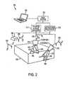
- FIG. 2illustrates an exemplary ultrasound imaging system 200 according to the present invention.
- the imaging system 200includes an ultrasound transmitter 205 having a transmitter reference frame 230; an ultrasound probe 210 having a probe reference frame 235; position and angle encoders 216 for measuring the position and orientation of the probe reference frame 235 relative to the transmitter reference frame 230; an ultrasound processor 215 for providing power and signals to, and receiving signals from, the ultrasound transmitter 205 and the ultrasound probe 210; a data system 220 for sending commands to and receiving data from the ultrasound processor 215 and the position and angle encoders 216; and a user interface 225 connected to the data system 220.
- the ultrasound probe 210may transmit and receive energy in a scan plane 242, which includes a plurality of pixels 240 within the scan plane 242 and having a pixel reference frame 245.
- the exemplary system 200acquires ultrasound images, through use of the ultrasound probe 210, within a 3D image space 255 having a construction reference frame 250. Further, the exemplary system 200 may include one or more phantoms 260 and 265, which are located such that they can be imaged by the ultrasound probe 210, and wherein the phantoms 260 and 265 may be acoustically coupled to a target (not shown) to be imaged within the 3D image space 255. By acoustically coupling, it is understood that continuity in the propagation medium is maintained such that sound waves pass through.
- FIG. 2further illustrates a single ultrasound probe 210 in two separate positions, Position 1 and 2, in which the probe 210 may acquire images of the phantoms 260 and 265.
- the probe 210may acquire images of the phantoms 260 and 265.
- there may be a single phantomwhich may be imaged by the ultrasound probe 210 from multiple positions and orientations.
- phantom 260will be referred to in the case in which there is a single phantom.
- two positionsare illustrated, at least three positions are generally required for computing the probe calibration matrix R T P according to the present invention.
- matrixas in the probe calibration matrix R T P , may refer to any representation of a spatial relationship between coordinate frames, such as a quaternion.
- this embodiment of the present inventionmay employ a SONOLINETM Antares ultrasound scanner manufactured by Siemens Medical Solutions, USA, Inc., Ultrasound Division, Issaqua, WA with a Siemens VF 10-5 linear array probe held in a rigid attachment mounted on an adjustable arm.
- SONOLINETM Antares ultrasound scannermanufactured by Siemens Medical Solutions, USA, Inc., Ultrasound Division, Issaqua, WA with a Siemens VF 10-5 linear array probe held in a rigid attachment mounted on an adjustable arm.
- the position and angle encoders 216include multiple optical markers attached to the ultrasound probe 210, which are tracked using, for example, an OPTOTRAKTM device, manufactured by Northern Digital, Inc. It will be readily apparent to one skilled in the art that alternate devices and systems for providing real-time measurements of position and orientation of the ultrasound probe 210 may be used and are within the scope of the present invention.
- the data system 220may include one or more computers, which may be networked together either locally or over a network.
- the data system 220includes software (hereinafter "the software") for implementing processes according to the present invention.
- the softwaremay be stored and run on the data system 220, or may be stored and run in a distributed manner between the data system 220, the ultrasound processor 215, and the user interface 225.
- FIG. 3illustrates an exemplary process 300 for providing real-time spatial calibration according to the present invention, which may be implemented by the software.
- Process 300may be used in conjunction with system 200, illustrated in FIG. 2 , in which a single phantom 260 is used.
- the ultrasound probe 210is placed in position 1 ofN, wherein N may be at least three.
- Position 1may be arbitrary or predetermined. Either way, the position should be such that the phantom 260 is within the scan plane 242 of ultrasound probe 240 wherein prominent feature points within the phantom 260 are readily identifiable in the acquired ultrasound image.
- the softwareacquires position and angle data of ultrasound probe 210 from the position and angle encoders 216 and stores the corresponding data values in memory.
- the softwaremay acquire and store position and angle data of the ultrasound probe 210 exclusively while the ultrasound probe 210 is in position 1, or the software may continuously acquire and store position and angle data values throughout exemplary process 300.
- the softwaremay provide time tag information corresponding to the position and angle data such that the time tag data may be used to synchronize the position and angle data with the ultrasound data acquired from the ultrasound processor 215.
- the ultrasound processor 215acquires and processes ultrasound image data from the ultrasound probe 210 while the ultrasound probe is held in position 1.
- the softwarethen receives ultrasound image data from the ultrasound processor 215 and stores the corresponding data values in memory.
- the softwaremay acquire ultrasound data continuously throughout exemplary process 300, along with time tag data, and may store the ultrasound and time tag data values so that the ultrasound data may be synchronized with similarly time tagged position and angle data acquired from the position and angle encoders 216. If the data system 220 continuously acquires and stores ultrasound data values throughout exemplary process 300, the data system may additionally acquire and store data from the user interface 225, along with corresponding time tag data, which may provide a flag indicating that ultrasound data values corresponding to a given time were acquired while the ultrasound probe was in position 1.
- step 340prominent feature points corresponding to the phantom 260 are identified from the ultrasound data acquired in step 330, as illustrated in FIG. 4 .
- the prominent feature pointsmay be selected by the user via the user interface 225 by, for example, selecting the point with a cursor and mouse-click.
- the softwaremay automatically identify prominent feature points using image processing techniques that are known to the art.
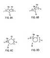
- FIG. 4illustrates an exemplary phantom 260, along with its reference frame 410, and a scan plane 242 impinging on the phantom 260.
- the phantom 260may include a matrix of N-shaped wires stretched between two parallel plates.
- a target volumesuch as a patient undergoing surgery
- the scan plane 242may intersect a plane defined by the phantom at points E, K, and Z, as illustrated in FIG. 4 .
- the softwarethen computes a coordinate transformation between the ultrasound probe reference frame 245 and the phantom reference frame 410.
- the transformationmay be accomplished by, for example, Horn's quaternion rigid registration method, as described in B. Horn, Closed-form solution of absolute orientation using unit quaternions, Journal of the Optical Society of America A, Vol. 4, page 629, April 1987 .
- Other techniquesmay be used, such as those employed to transform a set of points between coordinate systems, as is done in the fields of photogrammetry.
- the result of this transformationis a translation and rotation of the image of the phantom 260 from the phantom reference frame 410 to the pixel reference frame 245.
- step 360the software determines if there are more positions at which to acquire ultrasound data. If so, steps 310-350 are repeated for a new position.
- the next positionmay be chosen arbitrarily, or determined prior to executing the exemplary process 300.
- the next positionshould be chosen such that the phantom 260 is located within the scan plane 242 of the ultrasound probe 210, and that prominent feature points on the phantom 260 will be visible in the ultrasound imagery acquired by the ultrasound probe 210, as illustrated in FIG. 4 .
- steps 310-350are iterated 3 times.
- step 375the software retrieves the stored data values for the following: the translation and rotation of the phantom 260 from the phantom reference frame 410 to the pixel reference frame 245 when the ultrasound probe 240 was in each position; and the position and angle of the ultrasound probe 240, as measured by the position and angle encoders 216, when the ultrasound probe was in each position
- step 375the software assembles this data into a closed form formulation for determining the probe calibration matrix R T P according to the present invention and then derives the probe calibration matrix R T P from the closed form formulation.
- Iis an identity matrix
- R a12 and R a23are the rotations of the pixel reference frame 245 from position 1 to position 2, and from position 2 to position 3, respectively
- R b12 and R 232are the respective rotations of the probe reference frame 235 from position 1 to position 2 and from position 2 to
- R a and D uare obtained by estimating the translation and rotation of the prominent feature points of the phantom 260 between position 1 and 2; and R x , t x , and ⁇ are the values to be solved using the above formulation.
- the rotation and translation corresponding to the probe calibration matrix R T Pmay be derived by extracting a unique solution from the null space associated with the above formulation using the unity constraint to the first nine coefficients representing the rotation R x .
- extracting the null spaceinvolves solving the closed form solution and selecting the vector corresponding to the lowest coefficient.
- the left-most array in the closed form solutionmay be concatenated to include the I 9 -R a 12 ⁇ R b 12 0 9.3 and ⁇ t b ⁇ 12 t I 3 - R a 12 - D u 12 expressions for subsequent motions to additional positions.
- the more motions usedthe more precise the probe calibration matrix R T P , at the expense of speed of computation.
- the calibration matrixmay account for non-rigidity of the transformation between the pixel reference frame 245 and the probe reference frame 235, as opposed to a rigid transformation, in which case the scale factor ⁇ may be a scalar.
- the rigid transformation caseis described in the context of robotic hand-eye coordination by N. Andreff, R. Horaud, and B. Espiau, Robotic Hand-Eye Calibration Using Structure-from -Motion, The International Journal of Robotics Research, Vol. 20, No. 3, pp. 228-248 .
- ( ux, uy, uz )is the translation vector in number of pixels
- the scale factor ⁇converts the number of pixels into distance, such as millimeters.
- the softwaremay then store the constituent values of the probe calibration matrix R T P for use in subsequent pixel registration from the pixel reference frame 245 into the 3D image space 255 defined by the reference frame.
- FIG. 5illustrates still another embodiment of the present invention, where exemplary system 200 includes one or more docking stations 510 and 520.
- the docking stations 510 and 520are each in a substantially fixed position and orientation relative to the phantom 260, and each includes an acoustically coupled fixture for placing the ultrasound probe 210 in a precise position and angle relative to the construction frame 255.
- the usermay place the ultrasound probe 210 more precisely at each of the two positions, which may improve the precision and accuracy of the measured position and orientation of the probe reference frame 245.
- FIG. 6illustrates another embodiment of the present invention, in which imaging system 600 includes certain substantially similar components to exemplary system 200.
- system 600also includes three double-wedge phantoms 610 mounted on a base plate 620, which has a base plate reference frame 630; and a cross-wire structure 640, which is located such that it may be imaged by the ultrasound probe 210 simultaneously with any of the double-wedge phantoms 610.
- the base plate 620may have holes located and so that double-wedge phantoms 610 may be affixed to the base plate 620.
- the double-wedge phantoms 610may be precisely located so that their relative locations are precisely known.
- the double-wedge phantoms 610are rigidly mounted so that their relative locations are known to within 100 ⁇ m.
- the double-wedge phantoms 610 and the base plate 620may be immersed in an acoustically coupling material, such as a gel or water.
- Exemplary system 600may be used in conjunction with exemplary process 300.
- the ultrasound probe 210is positioned and oriented to acquire images of the double wedge phantom 610 at pose 1 in step 310.
- poserefers to the position and orientation of a given double-wedge phantom 610.
- Ultrasound images and probe position and angle datais then acquired in steps 320-350. Steps 310-350 may be iterated, whereby the position and orientation of the ultrasound probe 210 may be adjusted based on the translation and rotation determined in step 350.
- step 340the images of the double-wedge phantom 610 are identified in an ultrasound image.
- FIGs. 7A-7Dillustrate different scenarios in which an ultrasound beam 705 transmitted by the ultrasound probe 210 impinges on wedge features 710 and 720 of double-wedge phantom 610, and how the reflected energy from the transmitted beam 705 is distributed.
- FIGs. 8A-8Dillustrate how the wedges 710 and 720 may appear in a resulting ultrasound image 732.
- any translational offset or angular misalignment in the transmitted beam 705 relative to the pose of the double-wedge phantom 610is manifested in the ultrasound image 732.
- the ultrasound image 732as a form of feedback, the the position and orientation of the probe 210 may be adjusted to correct it for any misalignment and translational offset.
- FIGs. 7A and 8Acorrespond to a scenario in which the transmitted beam 705 is aligned with the pose of the double-wedge phantom 610 with no translational offset.
- Line 721refers to the "early echo,” or the first reflected energy of the transmitted beam 705 to impinge on either wedge 710 and 720.
- Line 722refers to the "late echo,” or the end of the reflected energy from the transmitted beam 705.
- Elements 725a and 725brefer to the geometry of the reflected energy, in which the dimension L corresponds to the length of the reflected energy, which is a function of the beam width BW and the slope of the wedge 710 or 720.
- FIG. 8Aillustrates an exemplary ultrasound image 732 corresponding to FIG. 7A .
- the acoustic energy reflected from wedge 710results in a "cloud" image 730a; and the acoustic energy reflected from wedge 720 results in cloud 730b.
- Features 730a and 730bare referred to as clouds since the acoustic energy in transmitted beam 705 spatially and temporally spreads as a result of the divergence of the transmitted beam 705, the shape of the acoustic pulse transmitted by the ultrasound probe 210, and the angle of the wedge from which the energy is reflected.
- clouds 730a and 730bhave substantially the same height, which corresponds to dimension L, which is due to the fact that the transmitted beam 705 impinges on wedges 710 and 720 at substantially the same (and opposite) angle. Further, clouds 730a and 730b are located substantially “side by side” in ultrasound image 732, which is due to the fact that there is substantially no translational offset between the center of the transmitted beam 705 and the point at which wedges 710 and 720 cross.
- FIG. 7Billustrates how acoustic energy may be reflected from wedges 710 and 720 when the transmitted beam 705 is angularly aligned with the pose of the double-wedge phantom 610, but in which the transmitted beam 705 has a translational offset relative to wedges 710 and 720.
- clouds 730a and 730bhave substantially the same height, but are offset from one another in a manner proportional to the translational offset of the transmitted beam 705.
- FIG. 7Cillustrates how acoustic energy may be reflected from wedges 710 and 720 when the transmitted beam is angularly misaligned (at angle ⁇ ) with the pose of the double-wedge phantom 610, but does not have any translational offset.
- angles other than 30°may be used, which may result in different sensitivities to angular misalignment and translational offset.
- FIG. 7Dillustrates how acoustic energy may be reflected from wedges 710 and 720 with a transmitted beam 705 impinging on the double-wedge phantom 610 with both an angular misalignment with the pose of the double-wedge phantom 610 and an translational offset.
- the resulting clouds 730a and 730b in the ultrasound image 732have different heights S and B, the difference of which is proportional to the misalignment angle; and the clouds 730a and 730b are offset in a manner proportional to the translational offset of the transmitted beam 705.
- the heights of the clouds 730a and 730b, and their offsetmay be determined automatically through image processing techniques known to the art.
- the heights of the clouds 730a and 730b and their offsetmay be determined by having the user place a cursor on the top and bottom of clouds 730a and 730b, and click a mouse.
- the cloud size differential and cloud offsetdetermined, the translation and rotation from the reference frame of the double-wedge phantom 610 to the pixel reference frame 245 may be determined.
- the usermay adjust the position and orientation of the ultrasound probe 210 to substantially eliminate the angular misalignment and translational offset of the ultrasound probe 210 relative to the double-wedge phantom 610.
- the usermay employ the ultrasound images of the wedges 710 and 720, like those illustrated in FIGs. 8A-8D , for feedback. If this is done, the translation and rotation between the reference frame of the double-wedge phantom 610 and the pixel reference frame 235 will be more precise.
- W k,k+ 1is known, since it depends on the precision to which the base plate 620 was machined and characterized.
- FIG. 9illustrates an exemplary double-wedge phantom 910 according to the present invention.
- the double-wedge phantom 910has multiple sets of wedges 710 and 720, each at different heights. Having multiple sets of wedges 710 and 720 at different heights substantially enable the divergence of the transmitted beam 705 to be characterized by determining the beam width BW at different heights, using the beam width equation described above.
- Exemplary system 600may be used in a "bootstrap calibration" procedure, in which the probe calibration matrix R T P is iteratively refined, and its accuracy and precision are improved.
- FIG. 10illustrates an exemplary process 1000 for performing bootstrap calibration according to the present invention.
- Exemplary process 1000includes process 300, in which ultrasound image data and probe position and angle data are collected.
- the ultrasound imagesinclude an image of one of the double-wedge phantoms 610 and the cross-wire structure 640.
- the bootstrapping calibration techniqueworks more effectively if the cross-wire structure 640 within the field of view of the ultrasound probe 210, but as far from the double-wedge phantom 610 as practicable.
- the ultrasound probe 210is placed such that it is sequentially centered and aligned relative to pose 1, pose 2, and pose 3.
- a probe calibration matrix R T Pis computed according to process 300.
- Process 300is implemented in such a way that a plurality of images may be acquired at each pose, and the mean and standard deviation corresponding to the resulting probe calibration matrices are computed.
- step 1010an inverse of the probe calibration matrix R T P is computed, and the ultrasound image is reconstructed according to the inverse probe calibration matrix R T P .
- the reconstructed ultrasound imageincludes a reconstructed image of the cross-wire structure 640.
- step 1020the reconstructed image of the cross-wire structure 640 is compared with an actual image of the cross-wire structure, and a standard deviation is computed between the two images.
- the accuracy of the reconstructed image of the cross-wire structure(and thus the accuracy of the probe calibration matrix R T P ) is assessed according to pre-determined accuracy requirements. If the probe calibration matrix R T P is deemed sufficiently accurate, the probe calibration matrix R T P is stored; if not, process 1000 proceeds to step 1030.
- step 1030the out-of-plane motion parameters are perturbed, and input into process 300 as a new estimate for the U k , the transformation matrix from the coordinate frame of the double-wedge phantom 610 at pose k to the pixel coordinate frame 245.
- the purpose of perturbing the U k matrixis to substantially encompass the range of values for the elements of the U k matrix such that the optimal version of U k will be selected.
- the system 200 illustrated in FIG. 2in conjunction with exemplary process 300 illustrated in FIG. 3 , may be implemented without the use of a phantom 260.
- image registrationmay be done by use of speckle correlation.
- Specklerefers to a situation in which a target tissue contains a plurality of small acoustic scatterers that form patterns of constructive and destructive interference within the tissue.
- the speckle patternis generally stable, and may provide a pattern with sufficient spatial variability to substantially enable computing correlations between successive ultrasound images.
Landscapes
- Health & Medical Sciences (AREA)
- Life Sciences & Earth Sciences (AREA)
- Engineering & Computer Science (AREA)
- Physics & Mathematics (AREA)
- Medical Informatics (AREA)
- Animal Behavior & Ethology (AREA)
- Radiology & Medical Imaging (AREA)
- Nuclear Medicine, Radiotherapy & Molecular Imaging (AREA)
- Biomedical Technology (AREA)
- Heart & Thoracic Surgery (AREA)
- Biophysics (AREA)
- Molecular Biology (AREA)
- Surgery (AREA)
- Pathology (AREA)
- General Health & Medical Sciences (AREA)
- Public Health (AREA)
- Veterinary Medicine (AREA)
- Computer Networks & Wireless Communication (AREA)
- General Physics & Mathematics (AREA)
- Radar, Positioning & Navigation (AREA)
- Remote Sensing (AREA)
- Ultra Sonic Daignosis Equipment (AREA)
Description
- The research and development effort associated with the subject matter of this patent application was supported by the National Science Foundation under grant no. ERC 9731478.
- The present invention involves the field of ultrasound imagery. More particularly, the present invention involves spatial calibration of ultrasound probes for intra-operative use.
- Computer Integrated Surgery has revolutionized surgical procedures, whereby 3D imagery of a target volume is created to enable a surgeon to more precisely and accurately position surgical tools within a patient. To serve this purpose, the imaging system, or guidance modality, should provide 3D imagery in real time; it must not be excessively obstructive or burdensome in an operating environment; and it must provide 3D imagery with sufficient accuracy and precision to provide effective surgical planning and execution.
- Ultrasound has become a popular guidance modality for medical procedures, due to its real-time operation, safety, low cost, and convenience of use in an operating room environment. Although it is not a "true 3D" imaging modality, such as Magnetic Resonance Imaging (MRI) and Computer Tomography (CT), techniques have been developed to convert multiple ultrasound 2D images into a 3D image in order to provide image guidance for surgeons while exploiting the benefits and conveniences of ultrasound.
- Components of a
conventional ultrasound system 100 are illustrated inFIG. 1 . Theultrasound system 100 includes atransmitter 105 having atransmitter reference frame 130; and anultrasound probe 110 having aprobe reference frame 135. Theultrasound probe 110 transmits and receives energy in ascan plane 142, and projects a plurality ofpixels 140 in apixel reference frame 145. Aconventional ultrasound system 100 may also includetracking sensors 125 to monitor the position and orientation of theultrasound probe 110. Theultrasound system 100 is used to collect multiple 2D ultrasound images, which are assembled into a3D image space 155 having a construction reference frame 150 (hereinafter "construction frame"). - In order to provide image guidance during a surgical procedure, 2D ultrasound images acquired by the
ultrasound system 100 must be registered or mapped in real-time into a3D image space 155, which encompasses a target volume within the patient undergoing surgery. Although there are ultrasound probes that acquire 3D images, these probes need to be spatially calibrated as well. Registering pixels frompixel reference frame 145 to the3D image space 155 requires a transformation matrix encompassing a series of constituent coordinate transformation matrices: e.g., from thepixel frame 145 to the ultrasoundprobe reference frame 135; from theultrasound probe frame 135 to thetransmitter reference frame 130; and from thetransmitter reference frame 130 to theconstruction frame 150. Of these transformation matrices, the most difficult to determine is the transformation matrix from thepixel reference frame 145 to the ultrasound probe reference frame 135 (hereinafter the "probe calibration matrix"). - According to the related art, spatial calibration is the act of determining each of the aforementioned transformation matrices, which is typically done before a medical procedure. In related art spatial calibration, the
ultrasound probe 110 is placed and oriented such that it acquires an image of a calibration target, or phantom, which has well defined spatial features. Using image processing techniques such as segmentation, the well defined features of the phantom are identified and located in the acquired ultrasound image, and the position and orientation of the phantom is derived from the segmented image. In the related art approach, images are acquired with theultrasound probe 110 placed in a single position and orientation. If the position and location of the phantom are known relative to theconstruction frame 155, the probe calibration matrix can be derived. By comparing the locations of the identified imaged features of the phantom with known locations and relative orientations of these features, the orientation of the phantom may be determined relative to the orientation of the ultrasound probe, and the probe calibration matrix may be derived by correlating the segmented images of the phantom with the phantom's known spatial characteristics. - Image processing techniques such as segmentation are computationally intensive and may not be feasible to compute in real time, based on the number of images acquired. Typical segmentation is performed on several hundred images. The large number of images not only requires time to process, but it increases the likelihood of errors that may render the probe calibration matrix invalid.
- According to the related art, once the transformation matrices, including the probe calibration matrix, are known, a
pixel 140 may be registered into the3D image space 155 defines by theconstruction frame 150. The transformation of apixel 140 location from thepixel reference frame 145 to theconstruction frame 155 can be expressed as:
wherePx is the location ofpixel 140 inpixel reference frame 145;Cx is the location ofpixel 140 inconstruction frame 155;RTP is the coordinate transformation matrix from thepixel reference frame 145 to the ultrasound probe reference frame 135 (i.e., the probe calibration matrix);TTR is the coordinate transformation from the ultrasoundprobe reference frame 135 to thetransmitter reference frame 130, which may be measured usingtracking sensors 125; andCTT is the coordinate transformation from thetransmitter reference frame 130 to theconstruction frame 155, which may be measured. - The accuracy and precision of registering
ultrasound image pixels 140 into theconstruction frame 155 is limited by the accuracy and precision of each of the above transformation matrices. The weakest link in this chain is the accuracy and precision of the probe calibration matrixRTP. Accordingly, a primary challenge in spatial calibration is in determining the probe calibrationmatrixRTP. - There are errors intrinsic to the conventional spatial calibration process that limit its precision and accuracy, including the following: imprecision in fabrication of the phantom, subsequent mechanical distortions of the phantom, lack of precision in characterizing the features of the phantom, spatial co-registration or ambiguities, and limits to numerical solution optimizations. As such, the quality of the calibration is limited to the accuracy and precision to which the phantom is characterized.
- Document
WO9907284 - An additional disadvantage of the related art spatial calibration is that since it cannot be performed intra-operatively, partly because it cannot be performed in real time, it is vulnerable to subsequent changes that may render any or all of the calibration matrices invalid without warning. Such post-calibration changes may be brought on by mechanical alteration to the tracking sensors and changes in tissue temperature. The effect of post-calibration changes may include inaccurate 3D image, resulting in incorrect surgical instrument placement.
- Although the above discussion involves ultrasound, the same issues may be encountered for any imaging system for which 2D images are assembled into a 3D image space. Or more generally, the same issues may arise in which a 2D imaging system is spatially calibrated in order to register image products into another reference frame.
- The present invention is defined in the two independent claims. Preferred embodiments are defined in the dependent claims.
- Accordingly, the present invention is directed to ultrasound calibration and real-time quality assurance based on closed form formulation that substantially obviates one or more of the problems due to limitations and disadvantages of the related art. In general, the present invention achieves this by deriving a probe calibration matrixRTP based on relative images of a phantom acquired from at least three positions and orientations, as opposed to deriving a probe calibration matrixRTP from images of the phantom, from one position and orientation, that is correlated with known characteristics of the phantom.
- An advantage of the present invention is to provide more reliable real-time ultrasound-based 3D imagery for use during medical procedures in that the ultrasound probe may be spatially calibrated intra-operatively. This helps mitigate post-calibration changes that may degrade the accuracy of 3D imagery without warning.
- Another advantage of the present invention is to provide a more efficient and robust spatial calibration of an ultrasound probe. By spatially calibrating the ultrasound probe based on the relative differences between two or more images of the same phantom, the resulting calibration is less dependent on the precision to which the spatial characteristics of the phantom are known.
- Another advantage of the present invention is to simplify the ultrasound probe calibration process. The present invention identifies pixels corresponding to prominent feature points on a phantom, as opposed to segmenting an image in order to reconstruct an image of the phantom, which is more computationally intensive.
- Additional features and advantages of the invention will be set forth in the description which follows, and in part will be apparent from the description, or may be learned by practice of the invention. The objectives and other advantages of the invention will be realized and attained by the structure particularly pointed out in the written description and claims hereof as well as the appended drawings.
- It is to be understood that both the foregoing general description and the following detailed description are exemplary and explanatory and are intended to provide further explanation of the invention as claimed.
- The accompanying drawings, which are included to provide a further understanding of the invention and are incorporated in and constitute a part of this specification, illustrate embodiments of the invention and together with the description serve to explain the principles of the invention.
FIG. 1 illustrates components of an ultrasound imaging system according to the related art;FIG. 2 illustrates an exemplary ultrasound imaging system according to the present invention;FIG. 3 illustrates an exemplary spatial calibration process according to the present invention;FIG. 4 illustrates an exemplary phantom according to the present invention;FIG. 5 illustrates an exemplary ultrasound imaging system, which includes at least one docking station;FIG. 6 illustrates an exemplary ultrasound imaging system that uses double-wedge phantoms;FIGs. 7A-7D illustrate the effects of misalignment and offset between an ultrasound probe and a double-wedge phantom, and their effects;FIGs. 8A-D illustrate ultrasound images, and how misalignment and offset between an ultrasound probe and a double-wedge phantom are apparent in the images;FIG. 9 illustrates an exemplary double-wedge phantom according to the present invention; andFIG. 10 illustrates an exemplary process for performing bootstrap calibration of an ultrasound probe according to the present invention.FIG. 2 illustrates an exemplaryultrasound imaging system 200 according to the present invention. Theimaging system 200 includes anultrasound transmitter 205 having atransmitter reference frame 230; anultrasound probe 210 having aprobe reference frame 235; position andangle encoders 216 for measuring the position and orientation of theprobe reference frame 235 relative to thetransmitter reference frame 230; anultrasound processor 215 for providing power and signals to, and receiving signals from, theultrasound transmitter 205 and theultrasound probe 210; adata system 220 for sending commands to and receiving data from theultrasound processor 215 and the position andangle encoders 216; and auser interface 225 connected to thedata system 220. Theultrasound probe 210 may transmit and receive energy in ascan plane 242, which includes a plurality ofpixels 240 within thescan plane 242 and having apixel reference frame 245.- The
exemplary system 200 acquires ultrasound images, through use of theultrasound probe 210, within a3D image space 255 having aconstruction reference frame 250. Further, theexemplary system 200 may include one ormore phantoms ultrasound probe 210, and wherein thephantoms 3D image space 255. By acoustically coupling, it is understood that continuity in the propagation medium is maintained such that sound waves pass through. FIG. 2 further illustrates asingle ultrasound probe 210 in two separate positions,Position probe 210 may acquire images of thephantoms ultrasound probe 210 from multiple positions and orientations. For purposes herein,phantom 260 will be referred to in the case in which there is a single phantom. Although two positions are illustrated, at least three positions are generally required for computing the probe calibration matrixRTP according to the present invention.- As used herein, the term "matrix," as in the probe calibration matrixRTP, may refer to any representation of a spatial relationship between coordinate frames, such as a quaternion.
- For the purposes of illustration, this embodiment of the present invention may employ a SONOLINE™ Antares ultrasound scanner manufactured by Siemens Medical Solutions, USA, Inc., Ultrasound Division, Issaqua, WA with a Siemens VF 10-5 linear array probe held in a rigid attachment mounted on an adjustable arm. However, it will be readily apparent to one skilled in the art that other commercially available ultrasound scanners may be used.
- In this exemplary embodiment of the present invention, the position and
angle encoders 216 include multiple optical markers attached to theultrasound probe 210, which are tracked using, for example, an OPTOTRAK™ device, manufactured by Northern Digital, Inc. It will be readily apparent to one skilled in the art that alternate devices and systems for providing real-time measurements of position and orientation of theultrasound probe 210 may be used and are within the scope of the present invention. - The
data system 220 may include one or more computers, which may be networked together either locally or over a network. Thedata system 220 includes software (hereinafter "the software") for implementing processes according to the present invention. The software may be stored and run on thedata system 220, or may be stored and run in a distributed manner between thedata system 220, theultrasound processor 215, and theuser interface 225. FIG. 3 illustrates anexemplary process 300 for providing real-time spatial calibration according to the present invention, which may be implemented by the software.Process 300 may be used in conjunction withsystem 200, illustrated inFIG. 2 , in which asingle phantom 260 is used.- In
step 310, theultrasound probe 210 is placed inposition 1 ofN, wherein N may be at least three.Position 1 may be arbitrary or predetermined. Either way, the position should be such that thephantom 260 is within thescan plane 242 ofultrasound probe 240 wherein prominent feature points within thephantom 260 are readily identifiable in the acquired ultrasound image. - In
step 320, the software acquires position and angle data ofultrasound probe 210 from the position andangle encoders 216 and stores the corresponding data values in memory. The software may acquire and store position and angle data of theultrasound probe 210 exclusively while theultrasound probe 210 is inposition 1, or the software may continuously acquire and store position and angle data values throughoutexemplary process 300. The software may provide time tag information corresponding to the position and angle data such that the time tag data may be used to synchronize the position and angle data with the ultrasound data acquired from theultrasound processor 215. - In
step 330, theultrasound processor 215 acquires and processes ultrasound image data from theultrasound probe 210 while the ultrasound probe is held inposition 1. The software then receives ultrasound image data from theultrasound processor 215 and stores the corresponding data values in memory. The software may acquire ultrasound data continuously throughoutexemplary process 300, along with time tag data, and may store the ultrasound and time tag data values so that the ultrasound data may be synchronized with similarly time tagged position and angle data acquired from the position andangle encoders 216. If thedata system 220 continuously acquires and stores ultrasound data values throughoutexemplary process 300, the data system may additionally acquire and store data from theuser interface 225, along with corresponding time tag data, which may provide a flag indicating that ultrasound data values corresponding to a given time were acquired while the ultrasound probe was inposition 1. - In
step 340, prominent feature points corresponding to thephantom 260 are identified from the ultrasound data acquired instep 330, as illustrated inFIG. 4 . The prominent feature points may be selected by the user via theuser interface 225 by, for example, selecting the point with a cursor and mouse-click. Alternatively, the software may automatically identify prominent feature points using image processing techniques that are known to the art. FIG. 4 illustrates anexemplary phantom 260, along with itsreference frame 410, and ascan plane 242 impinging on thephantom 260. In a particular embodiment, thephantom 260 may include a matrix of N-shaped wires stretched between two parallel plates. In order for thephantom 260 to be used intra-operatively, it should be acoustically coupled with a target volume, such as a patient undergoing surgery, such that the user may periodically position theultrasound probe 210 in a givenposition 1 andposition 2 during an operation. When being imaged by theultrasound probe 210, thescan plane 242 may intersect a plane defined by the phantom at points E, K, and Z, as illustrated inFIG. 4 . The x and y coordinate of the center pointK of thephantom 260 in thephantom reference frame 410 may be determined from the relations:
in whichxk andyk are the coordinates of the center image pointK of thephantom 260 in thephantom reference frame 410; xb andyb are the coordinates of point B on thephantom 260 in thephantom reference frame 410; andxc andyc are the coordinates of point C on thephantom 260 in thephantom reference frame 410.- In
step 350, with the coordinates of the center pointK determined, the software then computes a coordinate transformation between the ultrasoundprobe reference frame 245 and thephantom reference frame 410. The transformation may be accomplished by, for example, Horn's quaternion rigid registration method, as described inB. Horn, Closed-form solution of absolute orientation using unit quaternions, Journal of the Optical Society of America A, Vol. 4, page 629, April 1987. Other techniques may be used, such as those employed to transform a set of points between coordinate systems, as is done in the fields of photogrammetry. The result of this transformation is a translation and rotation of the image of the phantom 260 from thephantom reference frame 410 to thepixel reference frame 245. - In
step 360, the software determines if there are more positions at which to acquire ultrasound data. If so, steps 310-350 are repeated for a new position. The next position may be chosen arbitrarily, or determined prior to executing theexemplary process 300. The next position should be chosen such that thephantom 260 is located within thescan plane 242 of theultrasound probe 210, and that prominent feature points on thephantom 260 will be visible in the ultrasound imagery acquired by theultrasound probe 210, as illustrated inFIG. 4 . In a particular embodiment of the present invention, steps 310-350 are iterated 3 times. - In
step 375, the software retrieves the stored data values for the following: the translation and rotation of the phantom 260 from thephantom reference frame 410 to thepixel reference frame 245 when theultrasound probe 240 was in each position; and the position and angle of theultrasound probe 240, as measured by the position andangle encoders 216, when the ultrasound probe was in each position - In
step 375, the software assembles this data into a closed form formulation for determining the probe calibration matrixRTP according to the present invention and then derives the probe calibration matrixRTP from the closed form formulation. The closed form formulation is based on the homogeneous matrix equation AX=XB, in which A is the relative coordinate transformations between the locations of the respective pixels corresponding to the prominent feature points of the phantom; B is the relative coordinate transformation between ultrasound prove reference frame atposition 1 andposition 2, as measured by the position and angle encoders; and X is the probe calibration matrixRTP. This homogeneous matrix equation may be expressed in software as the following:
where I is an identity matrix;Ra12 andRa23 are the rotations of thepixel reference frame 245 fromposition 1 toposition 2, and fromposition 2 toposition 3, respectively;Rb12 andR232 are the respective rotations of theprobe reference frame 235 fromposition 1 toposition 2 and fromposition 2 toposition 3, as measured by the position andangle encoders 216;

probe reference frame 235 fromposition 1 toposition 2 and fromposition 2 toposition 3, as measured (for example, in mm) by the position andangle encoders 216;Du12 andDu12 are the translation vectors of thepixel reference frame 245 going fromposition 1 toposition 2;tx is the translation vector component corresponding to the calibration matrix (to be solved);Rx is the rotational component corresponding to the calibration matrix (to be solved); and λ is a vector of translational scale factors, wherein each scale factor converts the translation from number of pixels to a distance, such as millimeters. Of these variables,Ra andDu are obtained by estimating the translation and rotation of the prominent feature points of thephantom 260 betweenposition 
- The rotation and translation corresponding to the probe calibration matrixRTP may be derived by extracting a unique solution from the null space associated with the above formulation using the unity constraint to the first nine coefficients representing the rotationRx . As is known in the art, extracting the null space involves solving the closed form solution and selecting the vector corresponding to the lowest coefficient.
- If more than three positions are to be used, the left-most array in the closed form solution may be concatenated to include theI9-Ra12⊗ Rb12 09.3 and

- An alternate approach is to solve the above formulation in two steps, wherein the rotationRx is extracted first, and then the translationtx and its associated scale factor λ are subsequently extracted. By solving for and extracting the scale factor vector λ, the calibration matrix may account for non-rigidity of the transformation between the
pixel reference frame 245 and theprobe reference frame 235, as opposed to a rigid transformation, in which case the scale factor λ may be a scalar. The rigid transformation case is described in the context of robotic hand-eye coordination by N. Andreff, R. Horaud, and B. Espiau, Robotic Hand-Eye Calibration Using Structure-from -Motion, The International Journal of Robotics Research, Vol. 20, No. 3, pp. 228-248. - With the rotationRx,tx translation, and scale factor vector λ derived from the null space of the above formulation, the probe calibration matrixRTP may be assembled according to the following relation:

where (ux, uy, uz) is the translation vector in number of pixels, and the scale factor λ converts the number of pixels into distance, such as millimeters. - The software may then store the constituent values of the probe calibration matrixRTP for use in subsequent pixel registration from the
pixel reference frame 245 into the3D image space 255 defined by the reference frame. FIG. 5 illustrates still another embodiment of the present invention, whereexemplary system 200 includes one ormore docking stations docking stations phantom 260, and each includes an acoustically coupled fixture for placing theultrasound probe 210 in a precise position and angle relative to theconstruction frame 255. For example, by having twodocking stations position 1 and another atposition 2, the user may place theultrasound probe 210 more precisely at each of the two positions, which may improve the precision and accuracy of the measured position and orientation of theprobe reference frame 245.- Multiple ultrasound images may be acquired per position, with each image being used to compute a separate probe calibration matrix. For example, if 3 positions are used, and 10 images are acquired per position, then it is possible to compute 10x9x8=720 probe calibration matrices. Similarly, if 6 images are taken per position, if 3 positions are used, then 6x5x4=120 probe calibration matrices maybe generated. Computing the mean and standard deviation of any or all of these probe calibration matrices will provide an indication of the precision of the calibration.
FIG. 6 illustrates another embodiment of the present invention, in whichimaging system 600 includes certain substantially similar components toexemplary system 200. However,system 600 also includes three double-wedge phantoms 610 mounted on abase plate 620, which has a baseplate reference frame 630; and across-wire structure 640, which is located such that it may be imaged by theultrasound probe 210 simultaneously with any of the double-wedge phantoms 610. Thebase plate 620 may have holes located and so that double-wedge phantoms 610 may be affixed to thebase plate 620. The double-wedge phantoms 610 may be precisely located so that their relative locations are precisely known. In a particular embodiment, the double-wedge phantoms 610 are rigidly mounted so that their relative locations are known to within 100µm. The double-wedge phantoms 610 and thebase plate 620 may be immersed in an acoustically coupling material, such as a gel or water.Exemplary system 600 may be used in conjunction withexemplary process 300. In usingexemplary system 600, theultrasound probe 210 is positioned and oriented to acquire images of thedouble wedge phantom 610 atpose 1 instep 310. As used herein, "pose" refers to the position and orientation of a given double-wedge phantom 610. Ultrasound images and probe position and angle data is then acquired in steps 320-350. Steps 310-350 may be iterated, whereby the position and orientation of theultrasound probe 210 may be adjusted based on the translation and rotation determined instep 350.- In
step 340, the images of the double-wedge phantom 610 are identified in an ultrasound image.FIGs. 7A-7D illustrate different scenarios in which anultrasound beam 705 transmitted by theultrasound probe 210 impinges on wedge features 710 and 720 of double-wedge phantom 610, and how the reflected energy from the transmittedbeam 705 is distributed.FIGs. 8A-8D illustrate how thewedges ultrasound image 732. - Given the shape of the double-
wedge phantom 610, any translational offset or angular misalignment in the transmittedbeam 705 relative to the pose of the double-wedge phantom 610 is manifested in theultrasound image 732. By using theultrasound image 732 as a form of feedback, the the position and orientation of theprobe 210 may be adjusted to correct it for any misalignment and translational offset. FIGs. 7A and8A correspond to a scenario in which the transmittedbeam 705 is aligned with the pose of the double-wedge phantom 610 with no translational offset.Line 721 refers to the "early echo," or the first reflected energy of the transmittedbeam 705 to impinge on eitherwedge Line 722 refers to the "late echo," or the end of the reflected energy from the transmittedbeam 705.Elements wedge FIG. 8A illustrates anexemplary ultrasound image 732 corresponding toFIG. 7A . InFIG. 8A , the acoustic energy reflected fromwedge 710 results in a "cloud"image 730a; and the acoustic energy reflected fromwedge 720 results incloud 730b.Features beam 705 spatially and temporally spreads as a result of the divergence of the transmittedbeam 705, the shape of the acoustic pulse transmitted by theultrasound probe 210, and the angle of the wedge from which the energy is reflected. Since the transmittedbeam 705 is aligned with the pose of the double-wedge phantom,clouds beam 705 impinges onwedges clouds ultrasound image 732, which is due to the fact that there is substantially no translational offset between the center of the transmittedbeam 705 and the point at whichwedges - The beam width BW of the transmitted beam may be computed from the height L of
clouds FIG. 7B illustrates how acoustic energy may be reflected fromwedges beam 705 is angularly aligned with the pose of the double-wedge phantom 610, but in which the transmittedbeam 705 has a translational offset relative towedges FIG. 8B ,clouds beam 705.FIG. 7C illustrates how acoustic energy may be reflected fromwedges wedge phantom 610, but does not have any translational offset. As illustrated inFIG. 8C ,clouds 
where 30° is the magnitude of the angle ofwedges FIG. 7D illustrates how acoustic energy may be reflected fromwedges beam 705 impinging on the double-wedge phantom 610 with both an angular misalignment with the pose of the double-wedge phantom 610 and an translational offset. As illustrated inFIG. 8D , the resultingclouds ultrasound image 732 have different heights S and B, the difference of which is proportional to the misalignment angle; and theclouds beam 705.- In
step 350, the heights of theclouds clouds clouds wedge phantom 610 to thepixel reference frame 245 may be determined. - According to this exemplary embodiment of the present invention, the user may adjust the position and orientation of the
ultrasound probe 210 to substantially eliminate the angular misalignment and translational offset of theultrasound probe 210 relative to the double-wedge phantom 610. The user may employ the ultrasound images of thewedges FIGs. 8A-8D , for feedback. If this is done, the translation and rotation between the reference frame of the double-wedge phantom 610 and thepixel reference frame 235 will be more precise. - In
step 375, the software computes the closed form formulation as is done withexemplary system 200, except that the relative coordinate transformation A (from the aforementioned AX=XB homogeneous equation) may correspond to the following relation:
whereUk is the transformation matrix from the coordinate frame of the double-wedge phantom 610 at posek to the pixel coordinateframe 245;
wedge phantom 610 at posek+1 to the pixel coordinateframe 245; andWk,k+1 is the transformation matrix from the coordinate frame of the double-wedge phantom 610 at pose k to the double-wedge phantom 610 at posek+1. Of these,Wk,k+1 is known, since it depends on the precision to which thebase plate 620 was machined and characterized. With the closed form formulation assembled, the software extracts a unique solution from the null space instep 380. FIG. 9 illustrates an exemplary double-wedge phantom 910 according to the present invention. The double-wedge phantom 910 has multiple sets ofwedges wedges beam 705 to be characterized by determining the beam width BW at different heights, using the beam width equation described above.Exemplary system 600 may be used in a "bootstrap calibration" procedure, in which the probe calibration matrixRTP is iteratively refined, and its accuracy and precision are improved.FIG. 10 illustrates an exemplary process 1000 for performing bootstrap calibration according to the present invention.- Exemplary process 1000 includes
process 300, in which ultrasound image data and probe position and angle data are collected. In this case, the ultrasound images include an image of one of the double-wedge phantoms 610 and thecross-wire structure 640. The bootstrapping calibration technique works more effectively if thecross-wire structure 640 within the field of view of theultrasound probe 210, but as far from the double-wedge phantom 610 as practicable. Withinprocess 300, theultrasound probe 210 is placed such that it is sequentially centered and aligned relative to pose 1,pose 2, and pose 3. A probe calibration matrixRTP is computed according toprocess 300.Process 300 is implemented in such a way that a plurality of images may be acquired at each pose, and the mean and standard deviation corresponding to the resulting probe calibration matrices are computed. - In
step 1010, an inverse of the probe calibrationmatrixRTP is computed, and the ultrasound image is reconstructed according to the inverse probe calibration matrixRTP. The reconstructed ultrasound image includes a reconstructed image of thecross-wire structure 640. - In
step 1020, the reconstructed image of thecross-wire structure 640 is compared with an actual image of the cross-wire structure, and a standard deviation is computed between the two images. The accuracy of the reconstructed image of the cross-wire structure (and thus the accuracy of the probe calibration matrixRTP) is assessed according to pre-determined accuracy requirements. If the probe calibration matrixRTP is deemed sufficiently accurate, the probe calibration matrixRTP is stored; if not, process 1000 proceeds to step 1030. - In
step 1030, the out-of-plane motion parameters are perturbed, and input intoprocess 300 as a new estimate for theUk, the transformation matrix from the coordinate frame of the double-wedge phantom 610 at posek to the pixel coordinateframe 245. The purpose of perturbing theUk matrix is to substantially encompass the range of values for the elements of theUk matrix such that the optimal version ofUk will be selected. - In an additional embodiment of the present invention, the
system 200 illustrated inFIG. 2 , in conjunction withexemplary process 300 illustrated inFIG. 3 , may be implemented without the use of aphantom 260. In this exemplary embodiment, image registration may be done by use of speckle correlation. Speckle refers to a situation in which a target tissue contains a plurality of small acoustic scatterers that form patterns of constructive and destructive interference within the tissue. The speckle pattern is generally stable, and may provide a pattern with sufficient spatial variability to substantially enable computing correlations between successive ultrasound images.


Claims (20)
- A method for spatially calibrating an ultrasound probe (210), comprising:placing the ultrasound probe (210) in a first position and orientation relative to a phantom (260);measuring the first position and orientation of the ultrasound probe (210);acquiring a first ultrasound image of the phantom (260);determining a first spatial relationship between a phantom reference frame (410) and a pixel reference frame (245), based on the first ultrasound image;repositioning the ultrasound probe (210) in a second position and orientation relative to the phantom (260);measuring the second position and orientation of the ultrasound probe (210);acquiring a second ultrasound image of the phantom (260);determining a second spatial relationship between the phantom reference frame (410) and the pixel reference frame (245), based on the second ultrasound image;repositioning the ultrasound probe in a third position and orientation relative to the phantom;measuring the third position and orientation of the ultrasound probe;acquiring a third ultrasound image of the phantom;determining a third spatial relationship between the phantom reference frame and the pixel reference frame, based on the third ultrasound image; andcomputing a probe (210) calibration matrix by a closed form formulation based on the first position and orientation of the ultrasound probe (210), the first spatial relationship, the second position and orientation of the ultrasound probe (210), the second spatial relationship, the third position and orientation of the ultrasound probe, and the third spatial relationship,characterised in that the closed form formulation is based on homogeneous matrix equationAX=XB, in whichA is the relative coordinate transformations between the locations of the respective pixels corresponding to the prominent feature points of the phantom,B is a relative coordinate transformation of an ultrasound probe reference frame at successive measured positions, andX is the probe calibration matrixRTP.
- A method according to claim 1, further comprising acquiring position and orientation data from position and angle encoder (216).
- A method according to claim 1, wherein determining the first spatial relationship includes:identifying prominent phantom feature points in the first ultrasound image;identifying a center point of the phantom (260); anddetermining a coordinate transformation between the center point of the phantom (260) and a reference frame corresponding to the ultrasound probe (210).
- A method according to claim 3, wherein determining a coordinate transformation between the center point of the phantom (260) and a reference frame corresponding to the ultrasound probe (210) include:determining a translation between the center point of the phantom (260) and a pixel location in the reference frame of the ultrasound probe (210); anddetermining a rotation between the center point of the phantom (260) and a pixel location in the reference frame of the ultrasound probe (210).
- A method according to claim 4, wherein determining a rotation between the center point of the phantom (260) and a pixel location in the reference frame of the ultrasound probe (210) includes representing the rotation as a quaternion.
- A method according to claim 1, wherein determining a first spatial relationship includes representing the first spatial relationship as a quaternion.
- A method according to claim 1, wherein determining a first spatial relationship includes representing the first spatial relationship as a transformation matrix.
- A method according to claim 1, wherein computing a probe (210) calibration matrix includes:assembling the first position and orientation of the ultrasound probe (210), the first spatial relationship, the second position and orientation of the ultrasound probe (210), the second spatial relationship, the third position and orientation of the ultrasound probe and the third spatial relationship into the closed form formulation; andextracting a unique solution from a null space corresponding to the closed form formulation.
- A method according to claim 8, wherein extracting a unique solution includes using a unity constraint to a first nine coefficients representing a rotation component to the calibration matrix.
- A method according to claim 1, wherein computing a probe (210) calibration matrix includes:assembling the first position and orientation of the ultrasound probe (210), the first spatial relationship, the second position and orientation of the ultrasound probe (210), the second spatial relationship, the third position and orientation of the ultrasound probe and the third spatial relationship into the closed form formulation;extracting a rotational component from a null space corresponding to the closed form formulation;extracting a translational component from the null space corresponding to the closed form formulation; andextracting a vector of scale factors from the null space corresponding to the closed form formulation.
- A method according to claim 1, wherein measuring the first position and orientation of the ultrasound probe (210) includes using optical markers that are disposed on the ultrasound probe (210).
- A method according to claim 1, wherein placing the ultrasound probe (210) in a first position relative to a phantom (260) includes placing the ultrasound probe (210) in contact with a docking station (510), the docking station (510) having a position and orientation that is substantially fixed relative to the phantom (260).
- A system for performing intra-operative calibration of an ultrasound probe (210), comprising:a position and angle encoder (216) for measuring a position and angle of the ultrasound probe (210);a phantom providing a reference frame anda data system (220) having a computer readable medium encoded with a program for computing a probe calibration matrix according to a closed form formulation, and according to a relative change between a first location in a first ultrasound image, a second location in a second ultrasound image, and a third location in a third ultrasound image, wherein the first ultrasound image corresponds to a first ultrasound probe position, the second ultrasound image corresponds to a second ultrasound probe position; and the third ultrasound image corresponds to a third ultrasound probe position,characterised in that the closed form formulation is based on homogeneous matrix equationAX=XB, in whichA is the relative coordinate transformations between the locations of the respective pixels corresponding to the prominent feature points of the phantom,B is a relative coordinate transformation of an ultrasound probe reference frame at successive measured positions, andX is the probe calibration matrixRTP.
- A system according to claim 13, wherein the first location includes a prominent feature point.
- A system according to claim 13, wherein the first location includes a speckle pattern.
- A system according to claim 13, wherein the phantom (260) includes a wire arranged substantially in an N-shape.
- A system according to claim 13, wherein the phantom (260) includes two substantially parallel plates.
- A system according to claim 13, wherein the phantom (260) includes two wedges.
- A system according to claim 13, further comprising a docking station (510) having a substantially fixed position and orientation.
- A system according to claim 13, wherein the position and angle encoder (216) includes optical markers that are disposed on the ultrasound probe (210).
Applications Claiming Priority (2)
| Application Number | Priority Date | Filing Date | Title |
|---|---|---|---|
| US56246004P | 2004-04-15 | 2004-04-15 | |
| PCT/US2005/013026WO2005099581A1 (en) | 2004-04-15 | 2005-04-15 | Ultrasound calibration and real-time quality assurance based on closed form formulation |
Publications (3)
| Publication Number | Publication Date |
|---|---|
| EP1744676A1 EP1744676A1 (en) | 2007-01-24 |
| EP1744676A4 EP1744676A4 (en) | 2011-02-02 |
| EP1744676B1true EP1744676B1 (en) | 2015-07-22 |
Family
ID=35149728
Family Applications (1)
| Application Number | Title | Priority Date | Filing Date |
|---|---|---|---|
| EP05754852.1AExpired - LifetimeEP1744676B1 (en) | 2004-04-15 | 2005-04-15 | Ultrasound calibration and real-time quality assurance based on closed form formulation |
Country Status (3)
| Country | Link |
|---|---|
| US (1) | US7867167B2 (en) |
| EP (1) | EP1744676B1 (en) |
| WO (1) | WO2005099581A1 (en) |
Families Citing this family (50)
| Publication number | Priority date | Publication date | Assignee | Title |
|---|---|---|---|---|
| WO2007092054A2 (en) | 2006-02-06 | 2007-08-16 | Specht Donald F | Method and apparatus to visualize the coronary arteries using ultrasound |
| WO2008051639A2 (en) | 2006-10-25 | 2008-05-02 | Maui Imaging, Inc. | Method and apparatus to produce ultrasonic images using multiple apertures |
| US7832114B2 (en)* | 2007-04-04 | 2010-11-16 | Eigen, Llc | Tracker holder assembly |
| CN101689355A (en)* | 2007-06-15 | 2010-03-31 | 路迪亚公司 | Interactivity in the massive plate display |
| FR2917552B1 (en) | 2007-06-15 | 2009-08-28 | Sagem Defense Securite | METHOD FOR REGULATING THE TRANSMISSION GEIGE WITHIN A RECEPTION TERMINAL |
| US10226234B2 (en) | 2011-12-01 | 2019-03-12 | Maui Imaging, Inc. | Motion detection using ping-based and multiple aperture doppler ultrasound |
| US9282945B2 (en)* | 2009-04-14 | 2016-03-15 | Maui Imaging, Inc. | Calibration of ultrasound probes |
| US9788813B2 (en) | 2010-10-13 | 2017-10-17 | Maui Imaging, Inc. | Multiple aperture probe internal apparatus and cable assemblies |
| EP2207483B1 (en)* | 2007-10-19 | 2016-06-01 | Metritrack, Inc. | Three dimensional mapping display system for diagnostic ultrasound machines and method |
| FR2924810B1 (en)* | 2007-12-05 | 2012-09-28 | Univ Bretagne Occidentale | METHOD OF CALIBRATING ECHOGRAPHIC PROBES |
| WO2009143491A2 (en)* | 2008-05-22 | 2009-11-26 | The Trustees Of Dartmouth College | System and method for calibration for image-guided surgery |
| US10568535B2 (en) | 2008-05-22 | 2020-02-25 | The Trustees Of Dartmouth College | Surgical navigation with stereovision and associated methods |
| US8348846B2 (en)* | 2008-09-30 | 2013-01-08 | Mediri Gmbh | 3D motion detection and correction by object tracking in ultrasound images |
| US8727986B2 (en)* | 2009-02-27 | 2014-05-20 | Wisconsin Alumni Research Foundation | Method and apparatus for assessing risk of preterm delivery |
| KR101659723B1 (en) | 2009-04-14 | 2016-09-26 | 마우이 이미징, 인코포레이티드 | Multiple aperture ultrasound array alignment fixture |
| WO2011025943A2 (en)* | 2009-08-28 | 2011-03-03 | Dartmouth College | System and method for providing patient registration without fiducials |
| US9019262B2 (en)* | 2009-11-27 | 2015-04-28 | Hologic, Inc. | Systems and methods for tracking positions between imaging modalities and transforming a displayed three-dimensional image corresponding to a position and orientation of a probe |
| JP6274724B2 (en) | 2010-02-18 | 2018-02-07 | マウイ イマギング,インコーポレーテッド | Point source transmission and sound velocity correction using multi-aperture ultrasound imaging |
| US9610063B2 (en)* | 2010-03-26 | 2017-04-04 | The Johns Hopkins University | Methods and apparatus for ultrasound strain imaging |
| JP5848762B2 (en) | 2010-06-28 | 2016-01-27 | コーニンクレッカ フィリップス エヌ ヴェKoninklijke Philips N.V. | Real-time quality control of EM calibration |
| KR101906838B1 (en) | 2010-10-13 | 2018-10-11 | 마우이 이미징, 인코포레이티드 | Concave ultrasound transducers and 3d arrays |
| US9098904B2 (en) | 2010-11-15 | 2015-08-04 | Dartmouth College | System and method for registering ultrasound and magnetic resonance images |
| US8887551B2 (en)* | 2011-09-06 | 2014-11-18 | Trig Medical Ltd. | Calibration of instrument relative to ultrasonic probe |
| JP5863345B2 (en)* | 2011-09-08 | 2016-02-16 | キヤノン株式会社 | Subject information acquisition apparatus and subject information acquisition method |
| JP2015503404A (en) | 2011-12-29 | 2015-02-02 | マウイ イマギング,インコーポレーテッド | Arbitrary path M-mode ultrasound imaging |
| US11510600B2 (en) | 2012-01-04 | 2022-11-29 | The Trustees Of Dartmouth College | Method and apparatus for quantitative and depth resolved hyperspectral fluorescence and reflectance imaging for surgical guidance |
| JP6438769B2 (en) | 2012-02-21 | 2018-12-19 | マウイ イマギング,インコーポレーテッド | Determination of material hardness using multiple aperture ultrasound. |
| WO2013148673A1 (en) | 2012-03-26 | 2013-10-03 | Maui Imaging, Inc. | Systems and methods for improving ultrasound image quality by applying weighting factors |
| JP6270843B2 (en)* | 2012-08-10 | 2018-01-31 | マウイ イマギング,インコーポレーテッド | Calibration of multiple aperture ultrasonic probes |
| WO2014031642A1 (en) | 2012-08-21 | 2014-02-27 | Maui Imaging, Inc. | Ultrasound imaging system memory architecture |
| US20140064513A1 (en) | 2012-09-06 | 2014-03-06 | MUSIC Group IP Ltd. | System and method for remotely controlling audio equipment |
| EP2706372A1 (en)* | 2012-09-10 | 2014-03-12 | Esaote S.p.A. | Method and apparatus for ultrasound image acquisition |
| US9131922B2 (en) | 2013-01-29 | 2015-09-15 | Eigen, Inc. | Calibration for 3D reconstruction of medical images from a sequence of 2D images |
| WO2014160291A1 (en) | 2013-03-13 | 2014-10-02 | Maui Imaging, Inc. | Alignment of ultrasound transducer arrays and multiple aperture probe assembly |
| AU2014237346B2 (en) | 2013-03-15 | 2020-02-27 | Hologic, Inc. | System and method for reviewing and analyzing cytological specimens |
| US9883848B2 (en) | 2013-09-13 | 2018-02-06 | Maui Imaging, Inc. | Ultrasound imaging using apparent point-source transmit transducer |
| WO2015050941A1 (en)* | 2013-10-04 | 2015-04-09 | Battelle Memorial Institute | Contrast phantom for passive millimeter wave imaging systems |
| CA2948279A1 (en) | 2014-02-05 | 2015-08-13 | Verathon Inc. | Ultrasonic data collection |
| CN106462967B (en)* | 2014-05-14 | 2020-06-30 | 皇家飞利浦有限公司 | Acquisition orientation-related features for model-based segmentation of ultrasound images |
| CN106794007B (en) | 2014-08-18 | 2021-03-09 | 毛伊图像公司 | Network-based ultrasound imaging system |
| KR102681141B1 (en) | 2015-03-30 | 2024-07-02 | 마우이 이미징, 인코포레이티드 | Ultrasonic imaging systems and methods for detecting object motion |
| US10849650B2 (en) | 2015-07-07 | 2020-12-01 | Eigen Health Services, Llc | Transperineal needle guidance |
| CN108778530B (en) | 2016-01-27 | 2021-07-27 | 毛伊图像公司 | Ultrasound imaging with sparse array detectors |
| US11911223B2 (en)* | 2018-02-23 | 2024-02-27 | Brainlab Ag | Image based ultrasound probe calibration |
| US11559279B2 (en) | 2018-08-03 | 2023-01-24 | Bfly Operations, Inc. | Methods and apparatuses for guiding collection of ultrasound data using motion and/or orientation data |
| US20200037998A1 (en) | 2018-08-03 | 2020-02-06 | Butterfly Network, Inc. | Methods and apparatuses for guiding collection of ultrasound data using motion and/or orientation data |
| EP3988254A4 (en)* | 2019-07-19 | 2023-02-01 | Siemens Ltd., China | METHOD AND DEVICE FOR ROBOT HAND-EYE CALIBRATION, COMPUTING DEVICE, MEDIA AND PRODUCT |
| EP4114273B1 (en)* | 2020-03-05 | 2024-06-12 | Koninklijke Philips N.V. | Ultrasound imaging guidance and associated devices, systems, and methods |
| JP2022162869A (en)* | 2021-04-13 | 2022-10-25 | 富士フイルムヘルスケア株式会社 | Position registration method of ultrasonic probe, ultrasonic imaging system, position registration system for ultrasonic probe, phantom for ultrasonic probe position registration and position registration program for ultrasonic probe |
| CN113768535B (en)* | 2021-08-23 | 2024-06-28 | 武汉库柏特科技有限公司 | Method, system and device for self-calibrating gesture of ultrasonic profiling probe for teleoperation |
Family Cites Families (12)
| Publication number | Priority date | Publication date | Assignee | Title |
|---|---|---|---|---|
| DE4020019A1 (en)* | 1990-06-20 | 1992-01-02 | Cuba Acad Ciencias | Optical sensor calibration system e.g. for robot arm positioning - processes centre of brightness and rotation angle values derived from stored signals |
| DE69132412T2 (en)* | 1990-10-19 | 2001-03-01 | St. Louis University, St. Louis | LOCALIZATION SYSTEM FOR A SURGICAL PROBE FOR USE ON THE HEAD |
| US5810008A (en)* | 1996-12-03 | 1998-09-22 | Isg Technologies Inc. | Apparatus and method for visualizing ultrasonic images |
| GB9716994D0 (en)* | 1997-08-11 | 1997-10-15 | Univ Cambridge Tech | Ultrasound machine calibration |
| US6192735B1 (en)* | 1997-12-17 | 2001-02-27 | Nihon Kohden Corporation | Three-dimensional position calibrator |
| IL122839A0 (en)* | 1997-12-31 | 1998-08-16 | Ultra Guide Ltd | Calibration method and apparatus for calibrating position sensors on scanning transducers |
| JP4794708B2 (en)* | 1999-02-04 | 2011-10-19 | オリンパス株式会社 | 3D position and orientation sensing device |
| WO2001006924A1 (en)* | 1999-07-23 | 2001-02-01 | University Of Florida | Ultrasonic guidance of target structures for medical procedures |
| US6338716B1 (en)* | 1999-11-24 | 2002-01-15 | Acuson Corporation | Medical diagnostic ultrasonic transducer probe and imaging system for use with a position and orientation sensor |
| US20040218792A1 (en)* | 2003-04-29 | 2004-11-04 | Eastman Kodak Company | Probe position measurement to facilitate image registration and image manipulation in a medical application |
| US7090639B2 (en)* | 2003-05-29 | 2006-08-15 | Biosense, Inc. | Ultrasound catheter calibration system |
| US20050085718A1 (en)* | 2003-10-21 | 2005-04-21 | Ramin Shahidi | Systems and methods for intraoperative targetting |
- 2005
- 2005-04-15EPEP05754852.1Apatent/EP1744676B1/ennot_activeExpired - Lifetime
- 2005-04-15USUS11/578,071patent/US7867167B2/enactiveActive
- 2005-04-15WOPCT/US2005/013026patent/WO2005099581A1/enactiveApplication Filing
Non-Patent Citations (1)
| Title |
|---|
| 1 January 1989 (1989-01-01), XP055057514, Retrieved from the Internet <URL:http://ieeexplore.ieee.org/ielx4/70/2874/00088014.pdf?tp=&arnumber=88014&isnumber=2874> [retrieved on 20130322]* |
Also Published As
| Publication number | Publication date |
|---|---|
| WO2005099581A1 (en) | 2005-10-27 |
| EP1744676A4 (en) | 2011-02-02 |
| US20080269604A1 (en) | 2008-10-30 |
| EP1744676A1 (en) | 2007-01-24 |
| US7867167B2 (en) | 2011-01-11 |
Similar Documents
| Publication | Publication Date | Title |
|---|---|---|
| EP1744676B1 (en) | Ultrasound calibration and real-time quality assurance based on closed form formulation | |
| US9173715B2 (en) | Ultrasound CT registration for positioning | |
| EP2503934B1 (en) | Systems and methods for tracking positions between imaging modalities and transforming a displayed three-dimensional image corresponding to a position and orientation of a probe | |
| US7085400B1 (en) | System and method for image based sensor calibration | |
| US11995818B2 (en) | Synchronized surface and internal tumor detection | |
| US8831708B2 (en) | Multi-modal medical imaging | |
| US9138204B2 (en) | Method and apparatus for calibrating and re-aligning an ultrasound image plane to a navigation tracker | |
| US20090306509A1 (en) | Free-hand three-dimensional ultrasound diagnostic imaging with position and angle determination sensors | |
| EP2706372A1 (en) | Method and apparatus for ultrasound image acquisition | |
| CN105392428A (en) | System and method for mapping ultrasound shear wave elastography measurements | |
| WO2009132520A1 (en) | Three dimension ultrasound imaging system | |
| US20220313215A1 (en) | Ultrasound imaging device and method using position and posture tracking of probe of ultrasound scanner | |
| De Lorenzo et al. | Accurate calibration method for 3D freehand ultrasound probe using virtual plane | |
| EP1061848A1 (en) | Improvements in ultrasound techniques | |
| CN111184535A (en) | Handheld Unconstrained Scanning Wireless 3D Ultrasound Real-time Voxel Imaging System | |
| Lee et al. | Automated conformal ultrasound scanning for breast screening | |
| US6554769B1 (en) | Method and apparatus for determining the relative location of tomograph slices | |
| Aalamifar et al. | Enabling technologies for robot assisted ultrasound tomography | |
| Rousseau et al. | Quantitative evaluation of three calibration methods for 3-D freehand ultrasound | |
| Peterhans et al. | A fully automatic calibration framework for navigated ultrasound imaging | |
| Bao et al. | Tracked ultrasound for laparoscopic surgery | |
| JP2006095299A (en) | Ultrasonic diagnostic device | |
| WO2004086299A2 (en) | Device and method for correlation of an ultrasound image and an x-ray image |
Legal Events
| Date | Code | Title | Description |
|---|---|---|---|
| PUAI | Public reference made under article 153(3) epc to a published international application that has entered the european phase | Free format text:ORIGINAL CODE: 0009012 | |
| 17P | Request for examination filed | Effective date:20061114 | |
| AK | Designated contracting states | Kind code of ref document:A1 Designated state(s):AT BE BG CH CY CZ DE DK EE ES FI FR GB GR HU IE IS IT LI LT LU MC NL PL PT RO SE SI SK TR | |
| DAX | Request for extension of the european patent (deleted) | ||
| RIN1 | Information on inventor provided before grant (corrected) | Inventor name:VISWANATHAN, ARNAND Inventor name:FICHTINGER, GABOR Inventor name:HAGER, GREGORY, D. Inventor name:BOCTOR, EMAD, MOUSSA | |
| RAP1 | Party data changed (applicant data changed or rights of an application transferred) | Owner name:THE JOHNS HOPKINS UNIVERSITY | |
| A4 | Supplementary search report drawn up and despatched | Effective date:20110104 | |
| 17Q | First examination report despatched | Effective date:20110714 | |
| GRAP | Despatch of communication of intention to grant a patent | Free format text:ORIGINAL CODE: EPIDOSNIGR1 | |
| INTG | Intention to grant announced | Effective date:20141008 | |
| GRAS | Grant fee paid | Free format text:ORIGINAL CODE: EPIDOSNIGR3 | |
| GRAA | (expected) grant | Free format text:ORIGINAL CODE: 0009210 | |
| AK | Designated contracting states | Kind code of ref document:B1 Designated state(s):AT BE BG CH CY CZ DE DK EE ES FI FR GB GR HU IE IS IT LI LT LU MC NL PL PT RO SE SI SK TR | |
| REG | Reference to a national code | Ref country code:GB Ref legal event code:FG4D | |
| REG | Reference to a national code | Ref country code:CH Ref legal event code:EP | |
| REG | Reference to a national code | Ref country code:IE Ref legal event code:FG4D | |
| REG | Reference to a national code | Ref country code:AT Ref legal event code:REF Ref document number:737407 Country of ref document:AT Kind code of ref document:T Effective date:20150815 | |
| REG | Reference to a national code | Ref country code:DE Ref legal event code:R096 Ref document number:602005047039 Country of ref document:DE | |
| REG | Reference to a national code | Ref country code:SE Ref legal event code:TRGR | |
| REG | Reference to a national code | Ref country code:AT Ref legal event code:MK05 Ref document number:737407 Country of ref document:AT Kind code of ref document:T Effective date:20150722 | |
| REG | Reference to a national code | Ref country code:LT Ref legal event code:MG4D | |
| REG | Reference to a national code | Ref country code:NL Ref legal event code:FP | |
| PG25 | Lapsed in a contracting state [announced via postgrant information from national office to epo] | Ref country code:GR Free format text:LAPSE BECAUSE OF FAILURE TO SUBMIT A TRANSLATION OF THE DESCRIPTION OR TO PAY THE FEE WITHIN THE PRESCRIBED TIME-LIMIT Effective date:20151023 Ref country code:LT Free format text:LAPSE BECAUSE OF FAILURE TO SUBMIT A TRANSLATION OF THE DESCRIPTION OR TO PAY THE FEE WITHIN THE PRESCRIBED TIME-LIMIT Effective date:20150722 Ref country code:FI Free format text:LAPSE BECAUSE OF FAILURE TO SUBMIT A TRANSLATION OF THE DESCRIPTION OR TO PAY THE FEE WITHIN THE PRESCRIBED TIME-LIMIT Effective date:20150722 | |
| PG25 | Lapsed in a contracting state [announced via postgrant information from national office to epo] | Ref country code:AT Free format text:LAPSE BECAUSE OF FAILURE TO SUBMIT A TRANSLATION OF THE DESCRIPTION OR TO PAY THE FEE WITHIN THE PRESCRIBED TIME-LIMIT Effective date:20150722 Ref country code:IS Free format text:LAPSE BECAUSE OF FAILURE TO SUBMIT A TRANSLATION OF THE DESCRIPTION OR TO PAY THE FEE WITHIN THE PRESCRIBED TIME-LIMIT Effective date:20151122 Ref country code:PT Free format text:LAPSE BECAUSE OF FAILURE TO SUBMIT A TRANSLATION OF THE DESCRIPTION OR TO PAY THE FEE WITHIN THE PRESCRIBED TIME-LIMIT Effective date:20151123 Ref country code:ES Free format text:LAPSE BECAUSE OF FAILURE TO SUBMIT A TRANSLATION OF THE DESCRIPTION OR TO PAY THE FEE WITHIN THE PRESCRIBED TIME-LIMIT Effective date:20150722 Ref country code:PL Free format text:LAPSE BECAUSE OF FAILURE TO SUBMIT A TRANSLATION OF THE DESCRIPTION OR TO PAY THE FEE WITHIN THE PRESCRIBED TIME-LIMIT Effective date:20150722 | |
| REG | Reference to a national code | Ref country code:DE Ref legal event code:R097 Ref document number:602005047039 Country of ref document:DE | |
| PG25 | Lapsed in a contracting state [announced via postgrant information from national office to epo] | Ref country code:IT Free format text:LAPSE BECAUSE OF FAILURE TO SUBMIT A TRANSLATION OF THE DESCRIPTION OR TO PAY THE FEE WITHIN THE PRESCRIBED TIME-LIMIT Effective date:20150722 Ref country code:EE Free format text:LAPSE BECAUSE OF FAILURE TO SUBMIT A TRANSLATION OF THE DESCRIPTION OR TO PAY THE FEE WITHIN THE PRESCRIBED TIME-LIMIT Effective date:20150722 Ref country code:DK Free format text:LAPSE BECAUSE OF FAILURE TO SUBMIT A TRANSLATION OF THE DESCRIPTION OR TO PAY THE FEE WITHIN THE PRESCRIBED TIME-LIMIT Effective date:20150722 Ref country code:SK Free format text:LAPSE BECAUSE OF FAILURE TO SUBMIT A TRANSLATION OF THE DESCRIPTION OR TO PAY THE FEE WITHIN THE PRESCRIBED TIME-LIMIT Effective date:20150722 Ref country code:CZ Free format text:LAPSE BECAUSE OF FAILURE TO SUBMIT A TRANSLATION OF THE DESCRIPTION OR TO PAY THE FEE WITHIN THE PRESCRIBED TIME-LIMIT Effective date:20150722 | |
| PLBE | No opposition filed within time limit | Free format text:ORIGINAL CODE: 0009261 | |
| STAA | Information on the status of an ep patent application or granted ep patent | Free format text:STATUS: NO OPPOSITION FILED WITHIN TIME LIMIT | |
| PG25 | Lapsed in a contracting state [announced via postgrant information from national office to epo] | Ref country code:RO Free format text:LAPSE BECAUSE OF FAILURE TO SUBMIT A TRANSLATION OF THE DESCRIPTION OR TO PAY THE FEE WITHIN THE PRESCRIBED TIME-LIMIT Effective date:20150722 | |
| 26N | No opposition filed | Effective date:20160425 | |
| PG25 | Lapsed in a contracting state [announced via postgrant information from national office to epo] | Ref country code:BE Free format text:LAPSE BECAUSE OF NON-PAYMENT OF DUE FEES Effective date:20160430 Ref country code:SI Free format text:LAPSE BECAUSE OF FAILURE TO SUBMIT A TRANSLATION OF THE DESCRIPTION OR TO PAY THE FEE WITHIN THE PRESCRIBED TIME-LIMIT Effective date:20150722 | |
| REG | Reference to a national code | Ref country code:DE Ref legal event code:R119 Ref document number:602005047039 Country of ref document:DE | |
| REG | Reference to a national code | Ref country code:SE Ref legal event code:EUG | |
| REG | Reference to a national code | Ref country code:CH Ref legal event code:PL | |
| REG | Reference to a national code | Ref country code:NL Ref legal event code:MM Effective date:20160501 | |
| GBPC | Gb: european patent ceased through non-payment of renewal fee | Effective date:20160415 | |
| PG25 | Lapsed in a contracting state [announced via postgrant information from national office to epo] | Ref country code:LU Free format text:LAPSE BECAUSE OF FAILURE TO SUBMIT A TRANSLATION OF THE DESCRIPTION OR TO PAY THE FEE WITHIN THE PRESCRIBED TIME-LIMIT Effective date:20160415 | |
| REG | Reference to a national code | Ref country code:IE Ref legal event code:MM4A | |
| REG | Reference to a national code | Ref country code:FR Ref legal event code:ST Effective date:20161230 | |
| PG25 | Lapsed in a contracting state [announced via postgrant information from national office to epo] | Ref country code:FR Free format text:LAPSE BECAUSE OF NON-PAYMENT OF DUE FEES Effective date:20160502 Ref country code:CH Free format text:LAPSE BECAUSE OF NON-PAYMENT OF DUE FEES Effective date:20160430 Ref country code:LI Free format text:LAPSE BECAUSE OF NON-PAYMENT OF DUE FEES Effective date:20160430 Ref country code:NL Free format text:LAPSE BECAUSE OF NON-PAYMENT OF DUE FEES Effective date:20160501 Ref country code:GB Free format text:LAPSE BECAUSE OF NON-PAYMENT OF DUE FEES Effective date:20160415 Ref country code:DE Free format text:LAPSE BECAUSE OF NON-PAYMENT OF DUE FEES Effective date:20161101 | |
| PG25 | Lapsed in a contracting state [announced via postgrant information from national office to epo] | Ref country code:SE Free format text:LAPSE BECAUSE OF NON-PAYMENT OF DUE FEES Effective date:20160416 | |
| PG25 | Lapsed in a contracting state [announced via postgrant information from national office to epo] | Ref country code:IE Free format text:LAPSE BECAUSE OF NON-PAYMENT OF DUE FEES Effective date:20160415 | |
| PG25 | Lapsed in a contracting state [announced via postgrant information from national office to epo] | Ref country code:CY Free format text:LAPSE BECAUSE OF FAILURE TO SUBMIT A TRANSLATION OF THE DESCRIPTION OR TO PAY THE FEE WITHIN THE PRESCRIBED TIME-LIMIT Effective date:20150722 Ref country code:HU Free format text:LAPSE BECAUSE OF FAILURE TO SUBMIT A TRANSLATION OF THE DESCRIPTION OR TO PAY THE FEE WITHIN THE PRESCRIBED TIME-LIMIT; INVALID AB INITIO Effective date:20050415 | |
| PG25 | Lapsed in a contracting state [announced via postgrant information from national office to epo] | Ref country code:TR Free format text:LAPSE BECAUSE OF FAILURE TO SUBMIT A TRANSLATION OF THE DESCRIPTION OR TO PAY THE FEE WITHIN THE PRESCRIBED TIME-LIMIT Effective date:20150722 Ref country code:MC Free format text:LAPSE BECAUSE OF FAILURE TO SUBMIT A TRANSLATION OF THE DESCRIPTION OR TO PAY THE FEE WITHIN THE PRESCRIBED TIME-LIMIT Effective date:20150722 | |
| PG25 | Lapsed in a contracting state [announced via postgrant information from national office to epo] | Ref country code:BG Free format text:LAPSE BECAUSE OF FAILURE TO SUBMIT A TRANSLATION OF THE DESCRIPTION OR TO PAY THE FEE WITHIN THE PRESCRIBED TIME-LIMIT Effective date:20150722 |