EP1741239B1 - Intelligent adjunct network device - Google Patents
Intelligent adjunct network deviceDownload PDFInfo
- Publication number
- EP1741239B1 EP1741239B1EP05738102AEP05738102AEP1741239B1EP 1741239 B1EP1741239 B1EP 1741239B1EP 05738102 AEP05738102 AEP 05738102AEP 05738102 AEP05738102 AEP 05738102AEP 1741239 B1EP1741239 B1EP 1741239B1
- Authority
- EP
- European Patent Office
- Prior art keywords
- packet
- network device
- information
- ports
- forwarding
- Prior art date
- Legal status (The legal status is an assumption and is not a legal conclusion. Google has not performed a legal analysis and makes no representation as to the accuracy of the status listed.)
- Expired - Lifetime
Links
Images


Classifications
- H—ELECTRICITY
- H04—ELECTRIC COMMUNICATION TECHNIQUE
- H04L—TRANSMISSION OF DIGITAL INFORMATION, e.g. TELEGRAPHIC COMMUNICATION
- H04L12/00—Data switching networks
- H04L12/28—Data switching networks characterised by path configuration, e.g. LAN [Local Area Networks] or WAN [Wide Area Networks]
- H04L12/2854—Wide area networks, e.g. public data networks
- H—ELECTRICITY
- H04—ELECTRIC COMMUNICATION TECHNIQUE
- H04L—TRANSMISSION OF DIGITAL INFORMATION, e.g. TELEGRAPHIC COMMUNICATION
- H04L41/00—Arrangements for maintenance, administration or management of data switching networks, e.g. of packet switching networks
- H04L41/08—Configuration management of networks or network elements
- H04L41/0803—Configuration setting
- H04L41/0813—Configuration setting characterised by the conditions triggering a change of settings
- H—ELECTRICITY
- H04—ELECTRIC COMMUNICATION TECHNIQUE
- H04L—TRANSMISSION OF DIGITAL INFORMATION, e.g. TELEGRAPHIC COMMUNICATION
- H04L12/00—Data switching networks
- H04L12/02—Details
- H04L12/08—Allotting numbers to messages; Counting characters, words or messages
- H—ELECTRICITY
- H04—ELECTRIC COMMUNICATION TECHNIQUE
- H04L—TRANSMISSION OF DIGITAL INFORMATION, e.g. TELEGRAPHIC COMMUNICATION
- H04L41/00—Arrangements for maintenance, administration or management of data switching networks, e.g. of packet switching networks
- H04L41/04—Network management architectures or arrangements
- H—ELECTRICITY
- H04—ELECTRIC COMMUNICATION TECHNIQUE
- H04L—TRANSMISSION OF DIGITAL INFORMATION, e.g. TELEGRAPHIC COMMUNICATION
- H04L41/00—Arrangements for maintenance, administration or management of data switching networks, e.g. of packet switching networks
- H04L41/08—Configuration management of networks or network elements
- H04L41/0803—Configuration setting
- H04L41/0813—Configuration setting characterised by the conditions triggering a change of settings
- H04L41/082—Configuration setting characterised by the conditions triggering a change of settings the condition being updates or upgrades of network functionality
- H—ELECTRICITY
- H04—ELECTRIC COMMUNICATION TECHNIQUE
- H04L—TRANSMISSION OF DIGITAL INFORMATION, e.g. TELEGRAPHIC COMMUNICATION
- H04L41/00—Arrangements for maintenance, administration or management of data switching networks, e.g. of packet switching networks
- H04L41/12—Discovery or management of network topologies
- H—ELECTRICITY
- H04—ELECTRIC COMMUNICATION TECHNIQUE
- H04L—TRANSMISSION OF DIGITAL INFORMATION, e.g. TELEGRAPHIC COMMUNICATION
- H04L47/00—Traffic control in data switching networks
- H04L47/10—Flow control; Congestion control
Definitions
- the present inventionrelates to networking and, more particularly, to decreasing the number of points of management within a network.
- redundant switches and linksare often included in a network. If a switch or link fails, a redundant switch or link, already in place within the network, can quickly be enabled to replace the failed switch or link. Since the redundant switch or link can typically be enabled as a replacement more quickly than the failed component can be replaced or repaired, having redundant links and/or switching can provide a more reliable network.
- redundant componentsWhen redundant components are included within a network, it is often desirable to be able to use the redundant components during normal network operation, before the failure of corresponding components. For example, if two links are implemented between a pair of switches, it is desirable to use both links (as opposed to leaving one link idle) to provide increased bandwidth. However, if multiple redundant links are active at the same time, management of those links may be undesirably complicated (e.g., due to the need to avoid bridging loops). Similarly, if additional network devices are included within a network for redundancy purposes, the management of those network devices can become overly complicated. For example, if configuration changes need to be applied to a class of network devices, service personnel will need to apply the changes to all of the network devices in that class.
- US-B1-6 658 016discloses a packet switching fabric including means forming a data ring, means forming a control ring, and means forming a plurality of data communication network links each having at least one network node coupled thereto.
- the fabricfurther includes a plurality of output queuing controlled switching devices coupled together by the data ring means and the control ring means so that the network links can be selectively communicatively coupled.
- Each of the output queuing controlled switching devicesincludes control ring processing means operative to develop, transmit and receive control messages to and from adjacent ones of the devices via the control ring means.
- the control messagesprovide for controlling packet transfer operations including transmitting associated selected ones of the received data packets from the associated source device to the associated destination device via an associated source-destination channel path including associated ones of the data ring segments and an associated one of the memory unit links.
- a channel resource patrol messageis passed by each one of the devices, the patrol message carrying channel bandwidth information indicative of bandwidth available on the data ring means and bandwidth available on memory unit links.
- the control ring processing meansis responsive to the channel bandwidth information and operative to read and modify the channel bandwidth information for the purpose of managing data transfer via the data ring means and via each of the memory unit links.
- the present inventionis a method as defined in claim 1 of the appended claims. Also provided is a system as defined in claim 8.
- An intelligent adjunct network deviceincludes one or more adjunct forwarding engines, each of which is used to perform local forwarding and/or routing, one or more ports, which are used to communicate with locally-attached network clients and/or servers, and one or more uplink interfaces, which are used to communicate with one or more network devices.
- the intelligent adjunct network devicereceives configuration information from the network device(s) via the uplink interface.
- the intelligent adjunct network devicealso forwards packets that cannot be forwarded locally, or that the intelligent adjunct does not know how to forward, to the network device(s) via the uplink interface.
- a methodwhich is performed by an adjunct network device, involves receiving a packet via a first port of several ports.
- the packetincludes a destination address. If the destination address does not correspond to any of the ports, the packet is sent to an uplink interface. If the destination address does correspond to one of the ports, the packet is sent to that one of the ports.
- Program instructions executable to perform such a methodcan be stored on a computer readable medium.
- the methodcan involve downloading routing information to a forwarding engine via the uplink interface. Such a method can also involve sending an error notification to the uplink interface in response to detecting a conflict between local forwarding information and forwarding information received via the uplink interface. In one embodiment, the error notification includes the correct value of the forwarding information.
- information associated with the packetcan also be sent to the uplink interface. This information identifies the port via which the packet is received.
- the informationcan also include a destination identifier generated by performing a lookup for the destination address.
- the uplink interfaceis coupled to a link within a virtual link bundle.
- the virtual network devicewill not be allowed to send the packet via the virtual link bundle.
- an adjunct network deviceincludes several ports, an uplink interface, and an adjunct forwarding engine coupled to the ports and the uplink interface.
- a first portis configured to receive a packet, which includes a destination address.
- the adjunct forwarding engineis configured to send the packet to the uplink interface if the destination address is not associated with any of the ports.
- the packetis sent to one of the ports if the destination address is associated with the one of the ports.
- the adjunct network devicecan also include a controller configured to append a header to the packet before the packet is sent to the uplink interface.
- the headerincludes information identifying the first port.
- the headercan also include a destination identifier generated by performing a lookup for the destination address.
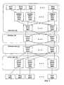
- FIG. 1is a block diagram of a network that includes several intelligent adjunct devices.
- clients 102(1)-102(n)communicate with each other and with several servers 104(1)-104(n) via a network.
- Clients 102(1)-102(n)can include a variety of different devices that access networked services.
- client 102(1)can be a cell phone
- client 102(2)can be a personal computer
- client 102(n)be a Personal Digital Assistant (PDA).
- Servers 104(1)-104(n)provide various services, such as various software-based services and/or access to shared storage devices.
- Access layer 110includes several adjunct network devices 120(1)-120(n). In this example, access layer 110 is the primary layer at which packets enter the network from clients 102(1)-102(n).
- Distribution layer 112aggregates flows received via access layer 110 and provides these aggregated flows to core layer 114.
- distribution layer 112includes network devices 122(1)-122(n).
- Core layer 114is a logically centralized portion of the network through which various aggregated flows pass.
- Core layer 114includes network devices 124(1)-124(n).
- data center 116includes two sets of network devices: network devices 126(1)-126(n) and intelligent adjunct network devices 128(1)-128(n).
- Intelligent adjunct network devices 128(1)-128(n)provide access to the network to various servers 104(1)-104(n).
- Network devices 126(1)-126(n)aggregate flows from intelligent adjunct network devices 128(1)-128(n) and provide the aggregated flows to core layer 114.
- networkswill not include the network layers illustrated in FIG. 1 (e.g., some of the layers can be combined and/or eliminated, and alternative layers can also be included in addition to and/or instead of those shown in FIG. 1 ).
- clients and serverscan be coupled to the network differently than shown in FIG. 1 (e.g., some clients and/or servers can be coupled to individual network devices in the core and/or distribution layers).
- the physical locations of devices relative to each othercan differ from the logical locations shown in FIG. 1 . For example, two devices in the same network layer can be physically located on different floors, in different buildings, or on different campuses. In contrast, two devices in different network layers can be located in the same room.
- Adjunct network devices 120(1)-120(n), intelligent adjunct devices 128(1)-128(n), and network devices 122(1)-122(n), 124(1)-124(n), and 126(1)-126(n)can include various routers, switches, gateways, and other network equipment. In many embodiments, only one network device, intelligent adjunct network device, or adjunct network device may be needed at each layer in order for the network to function. However, multiple such devices can be included at each layer, as shown in FIG. 1 , in order to provide redundancy and/or to provide additional bandwidth.
- each adjunct network device 120(1)-120(n) in access layer 110is coupled to distribution layer 112 by two (or more) different links.
- each network device 122(1)-122(n) in distribution layer 112is coupled to core layer 114 by two (or more) different links.
- Each intelligent adjunct network device 128(1)-128(n) in data center 116is coupled to network devices 126(1)-126(n) in data center 116 by two (or more) different links.
- each linkis an Ethernet link.
- Non-adjunct network devices coupled to adjunct network devicescontrol the operation of the adjunct network devices.
- network devices 126(1)-126(n)can configure intelligent adjunct network devices 128(1)-128(n) according to various routing protocols and perform control protocol processing for intelligent adjunct network devices 128(1)-128(n).
- network devices 122(1)-122(n)can configure adjunct network devices 120(1)-120(n). As shown in FIG.
- the controlling network devicesare located in inner network layers (i.e., layers that are closer to the core layer than adjunct and intelligent adjunct devices) relative to the adjunct and intelligent adjunct network devices, which are located at the edge layers of the network (i.e., the layers that provide direct access to clients and servers).
- adjunct and intelligent adjunct network devicesBy allowing adjunct and intelligent adjunct network devices to be controlled by other network devices, the number of points of management within the network is reduced. For example, if an upgrade needs to be applied to each network device within the network of FIG. 1 , a technician can manually upgrade each network device that controls a adjunct network device. For example, the technician can upgrade each network device 126(1)-126(n) in data center 116. These network devices can then automatically apply the upgrade (e.g., by sending updated forwarding table values) to the intelligent adjunct network devices 128(1)-128(n) controlled by network devices 126(1)-126(n).
- the techniciancan simply upgrade network devices 126(1)-126(n) and allow those network devices to automatically distribute the upgrades to adjunct network devices 128(1)-128(n).
- adjunct network devices 120(1)-120(n)are implemented without any decision-making capability (e.g., forwarding and/or routing capabilities) with regard to how packets are conveyed through the network. Since adjunct network devices 120(1)-120(n) lack local decision-making capabilities, adjunct network devices 120(1)-120(n) operate by simply sending any packets received from clients 102(1)-102(n) to network devices 122(1)-122(n). Network devices 122(1)-122(n) then decide (e.g., by forwarding and/or routing the packets) how to convey the packets through the network.
- decision-making capabilitye.g., forwarding and/or routing capabilities
- This configurationperforms well in access layer 110, where most traffic received by a given adjunct network device is not addressed to another device attached to the given adjunct network device.
- network traffic within data center 116tends to be switched locally. For example, a significant amount of traffic entering intelligent adjunct network device 128(1) from locally attached servers (or clients, not shown) will be addressed to other locally attached servers or clients (as opposed to being addressed to devices attached to other network devices).
- intelligent network adjunct devices 128(1)-128(n)have decision-making capabilities (e.g., forwarding and/or routing capabilities).
- FIG. 2Aillustrates how two intelligent adjunct network devices 128(1) and 128(2) can be coupled to network devices 126(1) and 126(2) in data center 116.
- network devices 126(1) and 126(2)provide redundant functionality within the network.
- Each intelligent adjunct network device 128(1) and 128(2)has redundant connections to network devices 126(1)-126(2).
- each intelligent adjunct network device 128(1) and 128(2)can be configured with at least one connection to each network device 126(1) and 126(2). This way, if one of the links between an intelligent adjunct network device and network devices 126(1) and 126(2) fail, or if one of network devices 126(1) and 126(2) fails, the intelligent adjunct network device will still be able to communicate with the rest of the network.
- FIG. 2Billustrates how intelligent adjunct network devices can be operated as virtual line cards.
- network devices 126(1)-126(2)operate intelligent adjunct network devices 128(1)-128(2) as if intelligent adjunct network devices 128(1)-128(2) were line cards of network devices 126(1)-126(2), despite the fact that intelligent adjunct network devices 128(1)-128(2) can actually be implemented in physically separate hardware from network devices 126(1)-126(2).
- network device 126(1)can operate at least a portion of each intelligent adjunct network device 128(1) and 128(2) as a virtual line card of network device 126(1).
- Control unit 220(1) within network device 126(1)can assign port identifiers to each port within the portion of each intelligent adjunct network device.
- Control unit 220(1)can also perform control protocol processing and generate routing information for use by intelligent adjunct network devices 128(1) and 128(2).
- the intelligent adjunct network devicecan associate information with that packet. For example, the intelligent adjunct network device can append a header containing the information to the packet.
- the headercan include the port identifier, assigned by control unit 220(1), of the port of the intelligent adjunct network device that originally received the packet.
- Network device 126(1)can use the header to determine the location of the device that sent the packet relative to the intelligent adjunct network device's ports. Network device 126(1) can then forward subsequently received packets that are addressed to that device to the appropriate port of the intelligent adjunct network device.
- network device 126(1)can append a header identifying the appropriate port of the intelligent adjunct network device to the packet and send the packet and the header to the intelligent adjunct network device.
- the intelligent adjunct network devicecan then perform a local forwarding table lookup and send the packet via the port identified in the header appended to the packet.
- Network device 126(2)can similarly operate at least a portion of each intelligent adjunct network device as a virtual line card.
- control unit 220(2) of network device 126(2)can configure one or more ports in each intelligent adjunct network device.
- Control unit 220(2)can also perform control protocol processing and generate routing information for use by intelligent adjunct network devices 128(1) and 128(2) when forwarding packets via those ports.
- each network device 126(1) and 126(2)controls a unique subset of the ports within each intelligent adjunct network device.
- network devices 126(1)-126(2)coordinate with each other in order to collectively control the same ports within each intelligent adjunct network device.
- Network devices, such as network devices 126(1) and 126(2), that control intelligent adjunct network devicesare referred to as controlling network devices.
- FIG. 3Aillustrates an embodiment in which network devices 126(1) and 126(2) coordinate with each other in order to implement virtual network device 202.
- network devices 126(1) and 126(2)are coupled by a pair of redundant links 360, referred to as virtual network device link 360.
- virtual network device link 360It is noted that fewer or additional links can be used to implement virtual network device link 360 in other embodiments.
- virtual network device 202can include more than two component network devices.
- Each intelligent adjunct network device 128(1)-128(2)is coupled to virtual network device 202 by two links (different numbers of links are used in other embodiments). In this example, each of those two links is coupled to a different one of network devices 126(1) and 126(2).
- the redundant links coupling each of intelligent adjunct network devices 128(1) and 128(2) to virtual network device 202can be operated as a single logical link, referred to herein as a virtual link bundle.
- intelligent adjunct network device 128(1)operates the two links coupling that intelligent adjunct network device to virtual network device 202 as a virtual link bundle 350(1).
- each interface in intelligent adjunct network device 128(1) that is coupled to one of the linksis included in an interface bundle for the corresponding virtual link bundle.
- Intelligent adjunct network device 128(2)similarly operates the two links coupling intelligent adjunct network device 128(2) to virtual network device 202 as virtual link bundle 350(2).
- virtual link bundles 350(1) and 350(2)are each operated as an EtherChannel (TM) or as an aggregated link, as defined in IEEE 802.3.
- TMEtherChannel
- each link in each virtual link bundleis operated independently of each other link in that virtual link bundle (as opposed to being operated as part of a single logical link).
- the links in virtual link bundles 350(1) and 350(2)are specialized links, referred to herein as uplinks.
- an interface within a network device 126(1) or 126(2) or intelligent adjunct network device 128(1) or 128(2) that is coupled to an uplinkis referred to herein as an uplink interface.
- Each uplinkis capable of conveying both a packet and additional information generated within one of the network devices. For example, if a packet is being conveyed on an uplink from one of intelligent adjunct network devices 128(1) or 128(2) to one of network devices 126(1) or 126(2), additional information conveyed on the uplink with the packet can include information identifying which of the adjunct network device's ports received the packet.
- the additional informationcan also include information indicating whether any decision-making (e.g., forwarding or routing) has already been performed for the packet by the sending device.
- use of uplinksallows network devices 126(1) and 126(2) to operate intelligent adjunct network devices 128(1) and 128(2) as virtual line cards.
- the use of uplinkscan also allow network devices 126(1)-126(2) to be able to perform decision-making (e.g., routing and/or forwarding) on packets for intelligent adjunct network devices 128(1) and 128(2) in certain situations.
- two interface bundlesare coupled to each virtual link bundle.
- One of these interface bundlesis located within a single intelligent adjunct network device while the other interface bundle spans multiple network devices at the controlling network device level.
- virtual link bundle 350(1)is coupled to two uplink interfaces within intelligent adjunct network device 128(1).
- Virtual link bundle 350(1)is also coupled to an interface bundle that includes one uplink interface in network device 126(1) and one uplink interface in network device 126(2).
- Network devices 126(1) and 126(2)can coordinate certain behaviors when sending packets via virtual link bundles 350(1) and 350(2) in order to act as a virtual network device 202 that, from the perspective of intelligent adjunct network devices 128(1)-128(2), appears to be a single logical network device. For example, whenever network device unit 126(2) receives a packet from one of the intelligent adjunct network devices and that packet's destination address is located behind uplink interface bundle 350(2), network device unit 126(2) sends the packet from the local uplink interface within the identified uplink interface bundle. Network device unit 126(2) can also provide a copy of the packet to network device unit 126(1), but network device unit 126(1) will not output this packet via its local uplink interface within the identified uplink interface bundle.
- an intelligent adjunct deviceonly receives one copy of the packet from virtual network device 202 (as opposed to receiving one copy from each network device 126(1) and 126(2) included in virtual network device 202) and the appearance of virtual network device 202 being a single entity is maintained.
- Intelligent adjunct network devices 128(1)-128(n)can interact with virtual network device 202 in the same way as the intelligent adjunct network devices would interact with a single physical device.
- each intelligent adjunct network deviceis coupled to a single device, virtual network device 202, as shown in FIG. 3B .
- FIG. 3BIn embodiments, such as the one shown in FIG. 3B , in which intelligent adjunct network devices 128(1) and 128(2) operate as if the intelligent adjunct network devices are connected to a single network device, the use of virtual link bundles 350(1) and 350(2) is simplified.
- intelligent adjunct network device 128(1)may select a link on which to send a particular packet based on Spanning Tree Protocol.
- Spanning Tree Protocolmay involve more overhead and/or be more restrictive with respect to which links can be used to send a given packet (e.g., Spanning Tree Protocol might block all but one of the links, preventing utilization of all but one non-blocked link) than if intelligent adjunct network device 128(1) simply views virtual network device 202 as a single entity.
- intelligent adjunct network device 128(1)can simply select a link on which to send a packet based on load-sharing constraints.
- intelligent adjunct network device 128(1)can simply continue to use the non-failed links within virtual link bundle 350(1).
- FIG. 3Cshows the manner in which virtual network device 202 can effectively include both network devices 126(1) and 126(2) and intelligent adjunct network devices 128(1) and 128(2), in the case where network devices 126(1) and 126(2) coordinate with each other in order to operate as a virtual network device and each intelligent adjunct network device 128(1) and 128(2) is operated as a virtual line card of network devices 126(1) and 126(2).
- management of each aspect of virtual network device 202can be centralized in one of network devices 126(1) and 126(2).
- each network device 126(1) and 126(2)controls a unique aspect of virtual network device 202.
- network device 126(1)can manage routing protocols for interfaces connected via virtual link bundle 350(1) while network device 126(2) manages routing protocols for interfaces connected via virtual link bundle 350(2).
- all of the aspects of virtual network device 202are controlled by the same network device 126(1) or 126(2).
- virtual network device 202By centralizing management of virtual network device 202, user management of virtual network device 202 can be simplified. For example, if configuration information needs to be updated, a service person can manually upgrade the configuration information on network device 126(1), which is currently controlling virtual network device 202. Network device 126(1) can then automatically distribute the updated information to network device 126(2), and network devices 126(1) and 126(2) can likewise automatically distribute the information to intelligent adjunct network devices 128(1) and 128(2).
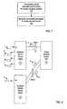
- FIG. 4is a block diagram of an intelligent adjunct network device.
- intelligent adjunct network device 128(1)can include several ports 402(1)-402(3), adjunct forwarding engine 404, and several uplink interfaces 406(1)-406(2). It is noted that fewer or additional ports, adjunct forwarding engines, and/or uplink interfaces can be included in other embodiments.
- intelligent adjunct network deviceincludes several line cards, each of which can include its own ports, adjunct forwarding engine, and/or uplink interfaces. It is also noted that the physical arrangement of and/or interconnections between components of intelligent adjunct device 128(2) can vary from the logical representation shown in FIG. 4 (e.g., ports 402(1)-402(3) and uplink interfaces 406(1)-406(2) can be coupled to adjunct forwarding engine 404 by an internal bus, in some embodiments).
- Ports 402(1)-402(3)are configured to be coupled to devices, such as servers 104(1)-104(n), that are to be interconnected by a network. Ports 402(1)-402(3) can provide ingress, egress, and/or ingress and egress functionality in order to send packets to and/or receive packets from these devices. Ports 402(1)-402(3) are viewed as local to a controlling virtual network device 202 (or to a controlling network device 126(1) or 126(2) in embodiments that do not implement virtual network devices) that controls intelligent adjunct network device 128(1). Uplink interfaces 406(1)-406(2) are configured to be coupled to uplinks to a controlling network device.
- uplink interfaces 406(1) and 406(2)are each coupled to a respective link within virtual link bundle 350(1) of FIGs. 3A-3C .
- Adjunct forwarding engine 404performs decision-making with respect to how packets received by intelligent adjunct network device 128(1) are conveyed through the network.
- a headeris appended to the packet.
- the headercan include information identifying which of ports 402(1)-402(3) originally received the packet.
- the headercan also include the result of a lookup performed by adjunct forwarding engine 404 (e.g., if adjunct forwarding engine 404 could not find a match for the packet's destination address in a lookup table, the header can indicate that the result of the lookup is that the packet is being flooded by intelligent adjunct network device 128(1)).
- This headercan be appended to the packet by a controller within the uplink interface 406(1) or 406(2) sending the packet or by a controller within adjunct forwarding engine 404.
- the packetcan also include a header, which has been generated by a controlling network device 126(1) or 126(2) or by another intelligent adjunct network device (e.g., intelligent adjunct network device 128(2)).
- This headercan include information identifying what forwarding and/or routing has been performed for the packet and/or the result of such forwarding and/or routing. For example, consider a packet and header received from network device 126(1). If network device 126(1) performed a lookup for the packet's destination address in a lookup table and determined that port 402(2) is the appropriate destination for the packet, the header can include information identifying port 402(2). If instead network device 126(1) could not find a match for the destination address in a lockup table, network device 126(1) can flood the packet. In that situation, the header appended to the packet can indicate that the packet should be flooded.
- adjunct forwarding engine 404is capable of performing only a subset of the tasks performed by a forwarding engine in a non-adjunct device.
- the forwarding engines included in network devices 126(1) and 126(2)forward packets and actively participate in various Layer 3 (L3) routing and Layer 2 (L2) control protocols.
- adjunct forwarding engine 404can forward packets but may not actively participate in all (or any) the various L3 routing and/or L2 control protocols.
- adjunct forwarding engine 404is configured to download L3 routing information and/or L2 control information from the network device (e.g., virtual network device 202) that controls intelligent adjunct network device 128(1).
- adjunct forwarding engine 404can receive one or more packets via uplink interfaces 406(1) and/or 406(2) that include L3 routing information generated by network devices 126(1) and/or 126(2). Adjunct forwarding engine 404 stores this information locally and uses the stored information to perform L3 routing for packets received via ports 402(1)-403(3). In embodiments where adjunct forwarding engine 404 is capable of performing only a subset of the forwarding and/or routing tasks, adjunct forwarding engine 404 can be implemented using less complex and/or less expensive hardware than would be necessary to implement the full set of forwarding and/or routing tasks.
- Adjunct forwarding engine 404performs its own Layer 2 (L2) learning and forwarding. For example, if a packet is received from a device having MAC (Media Access Control) address A via port 402(1), adjunct forwarding engine 404 can "learn" that MAC address A is behind port 402(1) by associating MAC address A with port 402(1). Adjunct forwarding engine 404 can associate MAC address A with port 402(1) by allocating a lookup table entry to MAC address A and storing information identifying port 402(2) in that entry. If a packet is later received via another port or via an uplink interface and that packet specifies MAC address A as its destination, adjunct forwarding engine 404 will send the packet to port 402(1).
- L2Layer 2
- adjunct forwarding engine 404When adjunct forwarding engine 404 cannot forward a packet locally, adjunct forwarding engine 404 causes the packet to be sent to a controlling network device via an uplink (e.g., by sending the packet to the uplink interface coupled to the appropriate uplink). Thus, if the packet's destination address does not correspond to one of ports 402(1)-402(3)), or if adjunct forwarding engine 404 does not know the location of the packet's destination address, adjunct forwarding engine 404 can cause the packet to be sent to one of uplink interfaces 406(1) and 406(2). For example, if the destination interface is on a different intelligent adjunct device or on a local port of one of the controlling network devices 126(1) and 126(2), adjunct forwarding engine 404 will select one of uplink interfaces 406(1) and 406(2).
- adjunct forwarding engine 404can cause the packet to be sent to each port corresponding to the multicast group as well as to one of uplink interfaces 406(1) and 406(2).
- Adjunct forwarding engine 404can also maintain consistency between locally generated forwarding information and forwarding information maintained by a controlling network device. For example, assume intelligent adjunct network device 128(1) receives a packet and header via one of uplink interfaces 406(1) and 406(2). Forwarding information included in the header is inconsistent with forwarding information maintained by adjunct forwarding engine 404. In response to detecting the inconsistency, intelligent adjunct network device 128(1) causes an error notification to be sent back to the sending network device (e.g., by sending the error notification to the appropriate uplink interface). This error notification can indicate that an inconsistency has been detected and can identify the particular information that is inconsistent. In some embodiments, the error notification can also include the correct value of the information.
- Intelligent adjunct network device 128(1)has detected this change, but other network devices (e.g., controlling network devices 126(1) and/or 126(2)) have not yet updated local forwarding information to reflect the change.
- Intelligent adjunct network device 128(1)receives a packet via uplink interface 406(1). The header of this packet indicates that port 402(2) is the destination of the packet, but forwarding information maintained by adjunct forwarding engine 404 indicates that port 402(1) is the correct destination. In response to this inconsistency, adjunct forwarding engine 404 causes an error notification to be sent to the sending device.
- This error notificationincludes, for example, the packet's destination address and the logical identifier of port 402(1).
- a packetis received via an uplink interface and the packet's header indicates that the packet is being flooded, and if adjunct forwarding engine 404 knows that the location of the packet's destination address is behind port 402(3), an error notification is sent.
- This error notificationincludes, for example, the logical identifier of port 402(3) and the packet's destination address.
- packets received via uplink interfaces 406(1) and 406(2)have headers indicating that routing has already been performed for those packets. In such a situation, no additional routing is performed for those packets by intelligent adjunct network device 128(1). It is noted that if intelligent adjunct network device 128(1) has already forwarded a packet via any local ports 402(1)-402(3), intelligent adjunct network device 128(1) should not later forward another copy of that packet via any of its local ports. For example, assume intelligent adjunct network device 128(1) floods a packet on each outgoing port (excluding the port via which the packet was originally received) and sends a copy of the packet and an appropriate header via uplink interface 406(1).
- network device 126(1)receives the packet and the header.
- Network device 126(1)also floods the packet, such that a copy of the packet is sent to any devices locally attached to network device 126(1), to intelligent adjunct network device 128(2) via virtual link bundle 350(2), and to network device 126(2) via virtual network device link 360 (as shown in FIG. 3A ).
- network device 126(2)receives the packet, it updates a value in the header to indicate that the packet was received from network device 126(1) (alternatively, network device 126(1) can update this value).
- network device 126(2)will prevent any copy of the packet from being sent via virtual link bundles 350(1) and 350(2), since network device 126(1) has already sent a copy of the packet on those virtual link bundles, if necessary. Accordingly, network devices within a virtual network device 202 can coordinate in order to prevent packets received from a particular intelligent adjunct network device from being sent back to that particular intelligent adjunct network device.
- FIG. 5is a flowchart showing the manner in which an intelligent adjunct network device can perform local forwarding.
- a packetis received via a port of an intelligent adjunct network device.
- the packetis received from a server connected to that port via an Ethernet link.
- the intelligent adjunct network devicelearns that the packet's source address is attached locally, as shown at 503.
- the intelligent adjunct network devicecan learn that the location of the sending device is behind the port via which the packet is received (at 501).
- the intelligent adjunct network devicecan learn the location by, for example, allocating an entry in a lookup table.
- the entrycan include the packet's source MAC address and the logical identifier of the port via which the packet was received.
- the intelligent adjunct network devicedetermines whether the intelligent adjunct network device knows the location of the destination device to which the packet is addressed. For example, the intelligent adjunct network device can input the packet's destination address to a lookup table. If a matching entry is found in the lookup table, the intelligent adjunct network device knows the location of the packet's destination device. If no matching entry is found (e.g., if the destination address misses in the look-up table), the intelligent adjunct network device does not know the location of the packet's destination device.
- the intelligent adjunct network devicedetermines whether all of the packet's destination device(s) are attached locally, as shown at 507. For example, if the packet is a unicast packet, the intelligent adjunct network device can look up the packet's destination address in a lookup table. If a matching entry for the destination address is found in the lookup table, and if the matching entry identifies a local port of the intelligent adjunct device, the intelligent adjunct network device can output the packet from the identified port, as shown at 509.
- the intelligent adjunct network deviceencapsulates the packet with a header and send the packet to a controlling network device via an uplink interface, as shown at 511.
- the headerincludes the result of the lookup and/or information identifying the port via which the packet was received (at 501).
- the intelligent adjunct network deviceencapsulates the packet and sends the encapsulated packet via the uplink interface, as shown at 511. If there are multiple uplinks coupling the intelligent adjunct network device to a controlling device (e.g., a virtual network device as shown in FIGs. 3A-3C ), the intelligent adjunct network device selects a single one of the uplinks via which to send the encapsulated packet. If some of the packet's destination devices are also attached locally, the intelligent adjunct network device can also send a copy of that packet to each locally attached destination device. For example, assume the packet's destination address is a multicast destination address that identifies a multicast group having three member devices.
- the intelligent adjunct network devicesends a copy of the packet to each of the locally attached devices in the multicast group.
- the intelligent adjunct network devicealso sends an encapsulated copy of the packet via the uplink interface for forwarding to the final device in the multicast group.
- the intelligent adjunct network deviceIf the intelligent adjunct network device does not know whether the destination device is attached locally (e.g., if the packet's destination address misses in a lookup table), the intelligent adjunct network device floods the packet, as shown at 513. When the packet is flooded, the intelligent adjunct network device sends a copy of the packet via each local port (other than the port via which the packet was received at 501). It is noted that in embodiments implementing VLANs (Virtual Local Area Networks), the packet is only flooded to ports in the same VLAN as that port that received the packet. The intelligent adjunct network device also sends an encapsulated copy of the packet via one of the uplinks.
- VLANsVirtual Local Area Networks
- FIG. 6is a flowchart illustrating the manner in which an intelligent adjunct network device can receive forwarding information via an uplink interface.
- the intelligent adjunct network devicereceives an encapsulated packet via an uplink interface.
- the packetis encapsulated with a header that includes forwarding information (e.g., such as a port identifier obtained by accessing a lookup table).
- the intelligent adjunct network devicedetermines whether the forwarding information appended to the packet is consistent with local forwarding information maintained by the intelligent adjunct network device. For example, the intelligent adjunct network device can provide the packet's destination address to a lookup table. If a matching entry is found, the intelligent adjunct network device can compare the information included in the matching entry to the information included in the packet's header. If the information is not consistent (e.g., if the header identifies a different port than the matching forwarding table entry identifies), the intelligent adjunct network device sends an indication of the inconsistency via the uplink interface, as shown at 605.
- the uplink interface via which this indication is sentcan be the same uplink interface that received the packet (at 601), or another uplink interface within the same interface bundle as the uplink interface that received the packet.
- the indication of the inconsistencycan include information identifying which information is inconsistent.
- the indicationcan include the destination address of the packet.
- the indication of the inconsistencycan also include the correct value of the forwarding information. For example, if the intelligent adjunct network device has learned that the destination device is behind a local port, but the header received via the uplink interface indicates that the packet is being flooded, the intelligent adjunct network device can include the packet's destination address and the port identifier of the local port in the indication of the inconsistency.
- the indication of the inconsistencyis a MAC notification in some embodiments.
- the intelligent adjunct network devicedoes not need to send an indication of the inconsistency via the uplink. Additionally, if the intelligent adjunct network device does not already know the location of the packet's destination, but the header appended to the packet identifies the location, the intelligent adjunct network device can update its local forwarding information to include the forwarding information appended to the packet, as shown at 607.
- FIG. 7illustrates a method of configuring an intelligent adjunct network device with L2 control information and L3 routing information.
- the intelligent adjunct network devicedownloads L3 routing information (e.g., in the form of one or more forwarding tables) and L2 control protocol information via an uplink interface.
- L3 routing informatione.g., in the form of one or more forwarding tables
- L2 control protocol informationvia an uplink interface.
- This downloadcan be initiated by the intelligent adjunct network device (e.g., upon being powered on or upon the detection of a possible inconsistency) or by the controlling network device (e.g., periodically or in response to the controlling network device updating its copy of the information).
- the intelligent adjunct network devicecan then use the downloaded information to perform local forwarding.
- the intelligent adjunct network devicegenerates L2 forwarding information for locally attached devices. For example, in response to receiving a packet from a locally attached server, the intelligent adjunct network device learns that the server is located behind a local port. Intelligent adjunct network device then uses this information to forward packets. Thus, the intelligent adjunct network device can forward packets based on both locally generated forwarding information and based on forwarding information downloaded from a controlling network device.
- FIG. 8shows how an intelligent adjunct network device can forward a packet, according to one embodiment of the present invention.
- two intelligent adjunct network devices 128(1) and 128(2)are coupled to virtual network device 202.
- Intelligent adjunct network device 128(1)is coupled to virtual network device 202 by virtual link bundle 350(1)
- intelligent adjunct network device 128(2)is coupled to virtual network device 202 by virtual link bundle 350(2).
- Both intelligent adjunct network device 128(1) and intelligent adjunct network device 128(2)can be operated as virtual line cards of virtual network device 202, as described above.
- virtual network device 202can perform routing and forwarding for the intelligent adjunct network devices.
- Virtual network device 202can also be configured to perform control protocol processing for the intelligent adjunct network devices.
- step 1intelligent adjunct network device 128(1) receives a packet from a locally attached device via port P1.
- Intelligent adjunct network devicedetermines whether the packet can be forwarded locally in step 2. For example, intelligent adjunct network device 128(1) looks up the packet's destination address in a forwarding table.
- intelligent adjunct network device 128(1)does not know the location of the packet's destination device (e.g., there is a forwarding table miss for the packet's destination address). As a result, intelligent adjunct network device 128(1) floods the packet, as shown in step 3. When the packet is flooded, a copy of the packet is output from each port other than P1. Another copy of the packet is output via one of the uplinks included in virtual link bundle 350(1).
- Virtual network device 202receives the copy of the packet sent via virtual link bundle 350(1).
- virtual network device 202determines how to forward the packet.
- virtual network device 202also does not know the location of the packet's destination, so virtual network device 202 floods the packet, as shown in step 5.
- virtual network device 202selects one of the uplinks in virtual link bundle 350(2) on which to send a copy of the packet to intelligent adjunct network device 128(2).
- This copy of the packetis encapsulated with a header that indicates that the packet is being flooded.
- Intelligent adjunct network device 128(2)receives the encapsulated packet via virtual link bundle 350(2).
- intelligent adjunct network device 128(2)determines whether the forwarding information in the header is consistent with local forwarding information generated by intelligent adjunct network device 128(2).
- intelligent adjunct network device 128(2)knows that the packet's destination address is located behind port P2. Accordingly, intelligent adjunct network device 128(2) outputs the packet via port P2, as shown in step 7.
- Intelligent adjunct network device 128(2)also outputs an error notification via one of the uplinks in virtual link bundle 350(2), as shown in step 8, due to the inconsistency between the forwarding information in the header and the local forwarding information.
- This error notificationcan include the packet's destination address and the logical identifier of port P2.
- virtual network device 202can learn the location of the destination device. Accordingly, subsequent packets addressed to the destination device will not be flooded by virtual network device 202. Virtual network device can also forward the error notification to intelligent adjunct network device 128(1) so that intelligent adjunct network device 128(1) will no longer flood packets being sent to that destination device.
- each intelligent adjunct network devicecan include a computer readable media upon which program instructions and/or data, useable to perform one or more of the methods shown in FIGs. 5 , 6 , and 7 , are stored.
- Such program instructionsare executable to detect the reception of packets, which are received by the adjunct network device via an interface.
- Exemplary types of computer readable mediainclude CDs (Compact Discs), DVDs (Digital Versatile Discs), hard disks, optical disks, tape devices, floppy disks, and memory (e.g., various types of RAM (Random Access Memory), ROM (Read Only Memory), flash memory, MEMS (Micro Electro-Mechanical Systems) memory, and the like).
- a network devicecan include one or more processors (e.g., microprocessors, PLDs (Programmable Logic Devices), or ASICs (Application Specific Integrated Circuits)) configured to execute program instructions stored in the computer readable media.
- the program instructions and/or datacan also be transferred to an intelligent adjunct network device via a network such as the Internet or upon a carrier medium.
- a computer readable mediumis a carrier medium such as a network and/or a wireless link upon which signals such as electrical, electromagnetic, or digital signals, on which the data and instructions are encoded, are conveyed.
- variable identifier "n"is used in several instances in the figures described herein to more simply designate the final element of a series of related or similar elements.
- the repeated use of such variable identifiersis not meant to necessarily imply a correlation between the sizes of such series of elements, although such correlation may exist.
- the use of such variable identifiersdoes not require that each series of elements have the same number of elements as another series delimited by the same variable identifier (e.g., the number of network devices in each network layer may vary). Rather, in each instance of use, the variable identified by "n" (or any other such identifier) may hold the same or a different value than other instances of the same variable identifier.
- Embodiments of the present inventioncan be used in the field of networking.
Landscapes
- Engineering & Computer Science (AREA)
- Computer Networks & Wireless Communication (AREA)
- Signal Processing (AREA)
- Data Exchanges In Wide-Area Networks (AREA)
Description
- The present invention relates to networking and, more particularly, to decreasing the number of points of management within a network.
- In order to provide increased network reliability, redundant switches and links are often included in a network. If a switch or link fails, a redundant switch or link, already in place within the network, can quickly be enabled to replace the failed switch or link. Since the redundant switch or link can typically be enabled as a replacement more quickly than the failed component can be replaced or repaired, having redundant links and/or switching can provide a more reliable network.
- When redundant components are included within a network, it is often desirable to be able to use the redundant components during normal network operation, before the failure of corresponding components. For example, if two links are implemented between a pair of switches, it is desirable to use both links (as opposed to leaving one link idle) to provide increased bandwidth. However, if multiple redundant links are active at the same time, management of those links may be undesirably complicated (e.g., due to the need to avoid bridging loops). Similarly, if additional network devices are included within a network for redundancy purposes, the management of those network devices can become overly complicated. For example, if configuration changes need to be applied to a class of network devices, service personnel will need to apply the changes to all of the network devices in that class. If the number of network devices is doubled in order to provide increased redundancy, the amount of service personnel effort needed to apply the changes will be doubled. Accordingly, it is desirable to be able to include redundant components in a network without undesirably increasing the expense of managing and maintaining the network.
- Background art is provided in
US-B1-6 658 016 , which discloses a packet switching fabric including means forming a data ring, means forming a control ring, and means forming a plurality of data communication network links each having at least one network node coupled thereto. The fabric further includes a plurality of output queuing controlled switching devices coupled together by the data ring means and the control ring means so that the network links can be selectively communicatively coupled. Each of the output queuing controlled switching devices includes control ring processing means operative to develop, transmit and receive control messages to and from adjacent ones of the devices via the control ring means. The control messages provide for controlling packet transfer operations including transmitting associated selected ones of the received data packets from the associated source device to the associated destination device via an associated source-destination channel path including associated ones of the data ring segments and an associated one of the memory unit links. A channel resource patrol message is passed by each one of the devices, the patrol message carrying channel bandwidth information indicative of bandwidth available on the data ring means and bandwidth available on memory unit links. The control ring processing means is responsive to the channel bandwidth information and operative to read and modify the channel bandwidth information for the purpose of managing data transfer via the data ring means and via each of the memory unit links. - The present invention is a method as defined in
claim 1 of the appended claims. Also provided is a system as defined inclaim 8. - Various embodiments of methods and systems for implementing intelligent adjunct network devices are disclosed. An intelligent adjunct network device includes one or more adjunct forwarding engines, each of which is used to perform local forwarding and/or routing, one or more ports, which are used to communicate with locally-attached network clients and/or servers, and one or more uplink interfaces, which are used to communicate with one or more network devices. The intelligent adjunct network device receives configuration information from the network device(s) via the uplink interface. The intelligent adjunct network device also forwards packets that cannot be forwarded locally, or that the intelligent adjunct does not know how to forward, to the network device(s) via the uplink interface.
- A method, which is performed by an adjunct network device, involves receiving a packet via a first port of several ports. The packet includes a destination address. If the destination address does not correspond to any of the ports, the packet is sent to an uplink interface. If the destination address does correspond to one of the ports, the packet is sent to that one of the ports. Program instructions executable to perform such a method can be stored on a computer readable medium.
- The method can involve downloading routing information to a forwarding engine via the uplink interface. Such a method can also involve sending an error notification to the uplink interface in response to detecting a conflict between local forwarding information and forwarding information received via the uplink interface. In one embodiment, the error notification includes the correct value of the forwarding information.
- If a packet is sent to the uplink interface, information associated with the packet can also be sent to the uplink interface. This information identifies the port via which the packet is received. The information can also include a destination identifier generated by performing a lookup for the destination address.
- In one embodiment, the uplink interface is coupled to a link within a virtual link bundle. In such a system, if a packet, sent via the uplink interface, is received at a virtual network device, the virtual network device will not be allowed to send the packet via the virtual link bundle.
- In some embodiments, an adjunct network device includes several ports, an uplink interface, and an adjunct forwarding engine coupled to the ports and the uplink interface. A first port is configured to receive a packet, which includes a destination address. The adjunct forwarding engine is configured to send the packet to the uplink interface if the destination address is not associated with any of the ports. The packet is sent to one of the ports if the destination address is associated with the one of the ports.
- The adjunct network device can also include a controller configured to append a header to the packet before the packet is sent to the uplink interface. The header includes information identifying the first port. The header can also include a destination identifier generated by performing a lookup for the destination address.
- The foregoing is a summary and thus contains, by necessity, simplifications, generalizations and omissions of detail; consequently, those skilled in the art will appreciate that the summary is illustrative only and is not intended to be in any way limiting. The operations disclosed herein may be implemented in a number of ways, and such changes and modifications may be made without departing from this invention and its broader aspects. Other aspects of the present invention, as defined solely by the claims, will become apparent in the non-limiting detailed description set forth below.
- A more complete understanding of the present invention may be acquired by referring to the following description and the accompanying drawings, in which like reference numbers indicate like features.
FIG. 1 is a block diagram of a network, according to one embodiment of the present invention.FIG. 2A illustrates how intelligent adjunct network devices can be coupled to other network devices, according to one embodiment of the present invention.FIG. 2B illustrates how intelligent adjunct network devices can be operated as virtual line cards, according to one embodiment of the present invention.FIGs. 3A-3C show how two network devices can operate as a single virtual network device, according to one embodiment of the present invention.FIG. 4 is a block diagram of an intelligent adjunct network device, according to one embodiment of the present invention.FIG. 5 is a flowchart showing the manner in which an intelligent adjunct network device can perform local forwarding, according to one embodiment of the present invention.FIG. 6 is a flowchart illustrating the manner in which an intelligent adjunct network device can receive forwarding information via an uplink interface, according to one embodiment of the present invention.FIG. 7 illustrates a method of configuring an intelligent adjunct network device with L2 and L3 information, according to one embodiment of the present invention.FIG. 8 shows how an intelligent adjunct network device can forward a packet, according to one embodiment of the present invention.- While the invention is susceptible to various modifications and alternative forms, specific embodiments of the invention are provided as examples in the drawings and detailed description. It should be understood that the drawings and detailed description are not intended to limit the invention to the particular form disclosed. Instead, the intention is to cover all modifications, equivalents and alternatives falling within the scope of the invention as defined by the appended claims.
FIG. 1 is a block diagram of a network that includes several intelligent adjunct devices. InFIG. 1 , several clients 102(1)-102(n) communicate with each other and with several servers 104(1)-104(n) via a network. Clients 102(1)-102(n) can include a variety of different devices that access networked services. For example, client 102(1) can be a cell phone, client 102(2) can be a personal computer, and client 102(n) be a Personal Digital Assistant (PDA). Servers 104(1)-104(n) provide various services, such as various software-based services and/or access to shared storage devices.- The network coupling clients 102(1)-102(n) and servers 104(1)-104(n) is described in terms of several network layers. The layer closest to clients 102(1)-102(n) is
access layer 110.Access layer 110 includes several adjunct network devices 120(1)-120(n). In this example,access layer 110 is the primary layer at which packets enter the network from clients 102(1)-102(n). Distribution layer 112 aggregates flows received viaaccess layer 110 and provides these aggregated flows tocore layer 114. In this example,distribution layer 112 includes network devices 122(1)-122(n).Core layer 114 is a logically centralized portion of the network through which various aggregated flows pass.Core layer 114 includes network devices 124(1)-124(n).- In this example,
data center 116 includes two sets of network devices: network devices 126(1)-126(n) and intelligent adjunct network devices 128(1)-128(n). Intelligent adjunct network devices 128(1)-128(n) provide access to the network to various servers 104(1)-104(n). Network devices 126(1)-126(n) aggregate flows from intelligent adjunct network devices 128(1)-128(n) and provide the aggregated flows tocore layer 114. - It is noted that in some embodiments, networks will not include the network layers illustrated in
FIG. 1 (e.g., some of the layers can be combined and/or eliminated, and alternative layers can also be included in addition to and/or instead of those shown inFIG. 1 ). Additionally, clients and servers can be coupled to the network differently than shown inFIG. 1 (e.g., some clients and/or servers can be coupled to individual network devices in the core and/or distribution layers). Additionally, the physical locations of devices relative to each other can differ from the logical locations shown inFIG. 1 . For example, two devices in the same network layer can be physically located on different floors, in different buildings, or on different campuses. In contrast, two devices in different network layers can be located in the same room. - Adjunct network devices 120(1)-120(n), intelligent adjunct devices 128(1)-128(n), and network devices 122(1)-122(n), 124(1)-124(n), and 126(1)-126(n) can include various routers, switches, gateways, and other network equipment. In many embodiments, only one network device, intelligent adjunct network device, or adjunct network device may be needed at each layer in order for the network to function. However, multiple such devices can be included at each layer, as shown in
FIG. 1 , in order to provide redundancy and/or to provide additional bandwidth. - Multiple links can be implemented between devices in different network layers to provide additional redundancy. For example, as shown in
FIG. 1 , each adjunct network device 120(1)-120(n) inaccess layer 110 is coupled todistribution layer 112 by two (or more) different links. Similarly, each network device 122(1)-122(n) indistribution layer 112 is coupled tocore layer 114 by two (or more) different links. Each intelligent adjunct network device 128(1)-128(n) indata center 116 is coupled to network devices 126(1)-126(n) indata center 116 by two (or more) different links. In one embodiment, each link is an Ethernet link. - Adjunct network devices 120(1)-120(n) and intelligent adjunct network devices 128(1)-128(n), respectively included in
access layer 110 anddata center 116, operate differently than network devices 122(1)-122(n), 124(1)-124(n), and 126(1)-126(n). Non-adjunct network devices coupled to adjunct network devices control the operation of the adjunct network devices. For example, network devices 126(1)-126(n) can configure intelligent adjunct network devices 128(1)-128(n) according to various routing protocols and perform control protocol processing for intelligent adjunct network devices 128(1)-128(n). Similarly, network devices 122(1)-122(n) can configure adjunct network devices 120(1)-120(n). As shown inFIG. 1 , the controlling network devices are located in inner network layers (i.e., layers that are closer to the core layer than adjunct and intelligent adjunct devices) relative to the adjunct and intelligent adjunct network devices, which are located at the edge layers of the network (i.e., the layers that provide direct access to clients and servers). - By allowing adjunct and intelligent adjunct network devices to be controlled by other network devices, the number of points of management within the network is reduced. For example, if an upgrade needs to be applied to each network device within the network of
FIG. 1 , a technician can manually upgrade each network device that controls a adjunct network device. For example, the technician can upgrade each network device 126(1)-126(n) indata center 116. These network devices can then automatically apply the upgrade (e.g., by sending updated forwarding table values) to the intelligent adjunct network devices 128(1)-128(n) controlled by network devices 126(1)-126(n). Thus, instead of having to manually upgrade each network device 126(1)-126(n) and each intelligent adjunct network device 128(1)-128(n), the technician can simply upgrade network devices 126(1)-126(n) and allow those network devices to automatically distribute the upgrades to adjunct network devices 128(1)-128(n). - In order to make remote management of adjunct network devices 120(1)-120(n) less complex, adjunct network devices 120(1)-120(n) are implemented without any decision-making capability (e.g., forwarding and/or routing capabilities) with regard to how packets are conveyed through the network. Since adjunct network devices 120(1)-120(n) lack local decision-making capabilities, adjunct network devices 120(1)-120(n) operate by simply sending any packets received from clients 102(1)-102(n) to network devices 122(1)-122(n). Network devices 122(1)-122(n) then decide (e.g., by forwarding and/or routing the packets) how to convey the packets through the network. This configuration performs well in
access layer 110, where most traffic received by a given adjunct network device is not addressed to another device attached to the given adjunct network device. In contrast, network traffic withindata center 116 tends to be switched locally. For example, a significant amount of traffic entering intelligent adjunct network device 128(1) from locally attached servers (or clients, not shown) will be addressed to other locally attached servers or clients (as opposed to being addressed to devices attached to other network devices). In order to be able to handle this type of traffic without needing assistance from network devices 126(1)-126(n), intelligent network adjunct devices 128(1)-128(n) have decision-making capabilities (e.g., forwarding and/or routing capabilities). FIG. 2A illustrates how two intelligent adjunct network devices 128(1) and 128(2) can be coupled to network devices 126(1) and 126(2) indata center 116. In this example, network devices 126(1) and 126(2) provide redundant functionality within the network. Each intelligent adjunct network device 128(1) and 128(2) has redundant connections to network devices 126(1)-126(2). As shown, each intelligent adjunct network device 128(1) and 128(2) can be configured with at least one connection to each network device 126(1) and 126(2). This way, if one of the links between an intelligent adjunct network device and network devices 126(1) and 126(2) fail, or if one of network devices 126(1) and 126(2) fails, the intelligent adjunct network device will still be able to communicate with the rest of the network.FIG. 2B illustrates how intelligent adjunct network devices can be operated as virtual line cards. Here, network devices 126(1)-126(2) operate intelligent adjunct network devices 128(1)-128(2) as if intelligent adjunct network devices 128(1)-128(2) were line cards of network devices 126(1)-126(2), despite the fact that intelligent adjunct network devices 128(1)-128(2) can actually be implemented in physically separate hardware from network devices 126(1)-126(2).- As shown, network device 126(1) can operate at least a portion of each intelligent adjunct network device 128(1) and 128(2) as a virtual line card of network device 126(1). Control unit 220(1) within network device 126(1) can assign port identifiers to each port within the portion of each intelligent adjunct network device. Control unit 220(1) can also perform control protocol processing and generate routing information for use by intelligent adjunct network devices 128(1) and 128(2).
- When an intelligent adjunct network device sends a packet to network device 126(1), the intelligent adjunct network device can associate information with that packet. For example, the intelligent adjunct network device can append a header containing the information to the packet. The header can include the port identifier, assigned by control unit 220(1), of the port of the intelligent adjunct network device that originally received the packet. Network device 126(1) can use the header to determine the location of the device that sent the packet relative to the intelligent adjunct network device's ports. Network device 126(1) can then forward subsequently received packets that are addressed to that device to the appropriate port of the intelligent adjunct network device. For example, if a packet is addressed to that device, network device 126(1) can append a header identifying the appropriate port of the intelligent adjunct network device to the packet and send the packet and the header to the intelligent adjunct network device. The intelligent adjunct network device can then perform a local forwarding table lookup and send the packet via the port identified in the header appended to the packet.
- Network device 126(2) can similarly operate at least a portion of each intelligent adjunct network device as a virtual line card. For example, control unit 220(2) of network device 126(2) can configure one or more ports in each intelligent adjunct network device. Control unit 220(2) can also perform control protocol processing and generate routing information for use by intelligent adjunct network devices 128(1) and 128(2) when forwarding packets via those ports. In one embodiment, each network device 126(1) and 126(2) controls a unique subset of the ports within each intelligent adjunct network device. In other embodiments, network devices 126(1)-126(2) coordinate with each other in order to collectively control the same ports within each intelligent adjunct network device. Network devices, such as network devices 126(1) and 126(2), that control intelligent adjunct network devices are referred to as controlling network devices.
- Within each network layer, multiple redundant network devices can be configured to collectively operate as a single virtual network device.
FIG. 3A illustrates an embodiment in which network devices 126(1) and 126(2) coordinate with each other in order to implementvirtual network device 202. In the illustrated example, network devices 126(1) and 126(2) are coupled by a pair ofredundant links 360, referred to as virtualnetwork device link 360. It is noted that fewer or additional links can be used to implement virtual network device link 360 in other embodiments. It is noted that in other embodiments,virtual network device 202 can include more than two component network devices. - Each intelligent adjunct network device 128(1)-128(2) is coupled to
virtual network device 202 by two links (different numbers of links are used in other embodiments). In this example, each of those two links is coupled to a different one of network devices 126(1) and 126(2). The redundant links coupling each of intelligent adjunct network devices 128(1) and 128(2) tovirtual network device 202 can be operated as a single logical link, referred to herein as a virtual link bundle. For example, intelligent adjunct network device 128(1) operates the two links coupling that intelligent adjunct network device tovirtual network device 202 as a virtual link bundle 350(1). In such an embodiment, each interface in intelligent adjunct network device 128(1) that is coupled to one of the links is included in an interface bundle for the corresponding virtual link bundle. Intelligent adjunct network device 128(2) similarly operates the two links coupling intelligent adjunct network device 128(2) tovirtual network device 202 as virtual link bundle 350(2). In some embodiments, virtual link bundles 350(1) and 350(2) are each operated as an EtherChannel (TM) or as an aggregated link, as defined in IEEE 802.3. In other embodiments, each link in each virtual link bundle is operated independently of each other link in that virtual link bundle (as opposed to being operated as part of a single logical link). - The links in virtual link bundles 350(1) and 350(2) are specialized links, referred to herein as uplinks. Similarly, an interface within a network device 126(1) or 126(2) or intelligent adjunct network device 128(1) or 128(2) that is coupled to an uplink is referred to herein as an uplink interface. Each uplink is capable of conveying both a packet and additional information generated within one of the network devices. For example, if a packet is being conveyed on an uplink from one of intelligent adjunct network devices 128(1) or 128(2) to one of network devices 126(1) or 126(2), additional information conveyed on the uplink with the packet can include information identifying which of the adjunct network device's ports received the packet. The additional information can also include information indicating whether any decision-making (e.g., forwarding or routing) has already been performed for the packet by the sending device. In some embodiments, use of uplinks allows network devices 126(1) and 126(2) to operate intelligent adjunct network devices 128(1) and 128(2) as virtual line cards. The use of uplinks can also allow network devices 126(1)-126(2) to be able to perform decision-making (e.g., routing and/or forwarding) on packets for intelligent adjunct network devices 128(1) and 128(2) in certain situations.
- In one embodiment, two interface bundles are coupled to each virtual link bundle. One of these interface bundles is located within a single intelligent adjunct network device while the other interface bundle spans multiple network devices at the controlling network device level. For example, virtual link bundle 350(1) is coupled to two uplink interfaces within intelligent adjunct network device 128(1). Virtual link bundle 350(1) is also coupled to an interface bundle that includes one uplink interface in network device 126(1) and one uplink interface in network device 126(2).
- Network devices 126(1) and 126(2) can coordinate certain behaviors when sending packets via virtual link bundles 350(1) and 350(2) in order to act as a
virtual network device 202 that, from the perspective of intelligent adjunct network devices 128(1)-128(2), appears to be a single logical network device. For example, whenever network device unit 126(2) receives a packet from one of the intelligent adjunct network devices and that packet's destination address is located behind uplink interface bundle 350(2), network device unit 126(2) sends the packet from the local uplink interface within the identified uplink interface bundle. Network device unit 126(2) can also provide a copy of the packet to network device unit 126(1), but network device unit 126(1) will not output this packet via its local uplink interface within the identified uplink interface bundle. This way, an intelligent adjunct device only receives one copy of the packet from virtual network device 202 (as opposed to receiving one copy from each network device 126(1) and 126(2) included in virtual network device 202) and the appearance ofvirtual network device 202 being a single entity is maintained. - Intelligent adjunct network devices 128(1)-128(n) can interact with
virtual network device 202 in the same way as the intelligent adjunct network devices would interact with a single physical device. Thus, for the purposes of routing protocols such as spanning tree, each intelligent adjunct network device is coupled to a single device,virtual network device 202, as shown inFIG. 3B . In embodiments, such as the one shown inFIG. 3B , in which intelligent adjunct network devices 128(1) and 128(2) operate as if the intelligent adjunct network devices are connected to a single network device, the use of virtual link bundles 350(1) and 350(2) is simplified. For example, if intelligent adjunct network device 128(1) is aware that virtual link bundle 350(1) terminates at two different network devices, intelligent adjunct network device 128(1) may select a link on which to send a particular packet based on Spanning Tree Protocol. The use of Spanning Tree Protocol may involve more overhead and/or be more restrictive with respect to which links can be used to send a given packet (e.g., Spanning Tree Protocol might block all but one of the links, preventing utilization of all but one non-blocked link) than if intelligent adjunct network device 128(1) simply viewsvirtual network device 202 as a single entity. When viewingvirtual network device 202 as a single entity, for example, intelligent adjunct network device 128(1) can simply select a link on which to send a packet based on load-sharing constraints. Similarly, if a link within virtual link bundle 350(1) fails, there is no need for intelligent adjunct network device 128(1) to change how Spanning Tree Protocol is applied. Instead, intelligent adjunct network device 128(1) can simply continue to use the non-failed links within virtual link bundle 350(1). FIG. 3C shows the manner in whichvirtual network device 202 can effectively include both network devices 126(1) and 126(2) and intelligent adjunct network devices 128(1) and 128(2), in the case where network devices 126(1) and 126(2) coordinate with each other in order to operate as a virtual network device and each intelligent adjunct network device 128(1) and 128(2) is operated as a virtual line card of network devices 126(1) and 126(2). When operated in this way, management of each aspect ofvirtual network device 202 can be centralized in one of network devices 126(1) and 126(2). In some embodiments, each network device 126(1) and 126(2) controls a unique aspect ofvirtual network device 202. For example, network device 126(1) can manage routing protocols for interfaces connected via virtual link bundle 350(1) while network device 126(2) manages routing protocols for interfaces connected via virtual link bundle 350(2). In other embodiments, all of the aspects ofvirtual network device 202 are controlled by the same network device 126(1) or 126(2).- By centralizing management of
virtual network device 202, user management ofvirtual network device 202 can be simplified. For example, if configuration information needs to be updated, a service person can manually upgrade the configuration information on network device 126(1), which is currently controllingvirtual network device 202. Network device 126(1) can then automatically distribute the updated information to network device 126(2), and network devices 126(1) and 126(2) can likewise automatically distribute the information to intelligent adjunct network devices 128(1) and 128(2). FIG. 4 is a block diagram of an intelligent adjunct network device. As shown, intelligent adjunct network device 128(1) can include several ports 402(1)-402(3),adjunct forwarding engine 404, and several uplink interfaces 406(1)-406(2). It is noted that fewer or additional ports, adjunct forwarding engines, and/or uplink interfaces can be included in other embodiments. For example, in one embodiment, intelligent adjunct network device includes several line cards, each of which can include its own ports, adjunct forwarding engine, and/or uplink interfaces. It is also noted that the physical arrangement of and/or interconnections between components of intelligent adjunct device 128(2) can vary from the logical representation shown inFIG. 4 (e.g., ports 402(1)-402(3) and uplink interfaces 406(1)-406(2) can be coupled toadjunct forwarding engine 404 by an internal bus, in some embodiments).- Ports 402(1)-402(3) are configured to be coupled to devices, such as servers 104(1)-104(n), that are to be interconnected by a network. Ports 402(1)-402(3) can provide ingress, egress, and/or ingress and egress functionality in order to send packets to and/or receive packets from these devices. Ports 402(1)-402(3) are viewed as local to a controlling virtual network device 202 (or to a controlling network device 126(1) or 126(2) in embodiments that do not implement virtual network devices) that controls intelligent adjunct network device 128(1). Uplink interfaces 406(1)-406(2) are configured to be coupled to uplinks to a controlling network device. In this example, uplink interfaces 406(1) and 406(2) are each coupled to a respective link within virtual link bundle 350(1) of
FIGs. 3A-3C .Adjunct forwarding engine 404 performs decision-making with respect to how packets received by intelligent adjunct network device 128(1) are conveyed through the network. - When a packet is sent via one of uplink interfaces 406(1)-406(2), a header is appended to the packet. The header can include information identifying which of ports 402(1)-402(3) originally received the packet. The header can also include the result of a lookup performed by adjunct forwarding engine 404 (e.g., if
adjunct forwarding engine 404 could not find a match for the packet's destination address in a lookup table, the header can indicate that the result of the lookup is that the packet is being flooded by intelligent adjunct network device 128(1)). This header can be appended to the packet by a controller within the uplink interface 406(1) or 406(2) sending the packet or by a controller withinadjunct forwarding engine 404. - When a packet is received via one of uplink interfaces 406(1)-406(2), the packet can also include a header, which has been generated by a controlling network device 126(1) or 126(2) or by another intelligent adjunct network device (e.g., intelligent adjunct network device 128(2)). This header can include information identifying what forwarding and/or routing has been performed for the packet and/or the result of such forwarding and/or routing. For example, consider a packet and header received from network device 126(1). If network device 126(1) performed a lookup for the packet's destination address in a lookup table and determined that port 402(2) is the appropriate destination for the packet, the header can include information identifying port 402(2). If instead network device 126(1) could not find a match for the destination address in a lockup table, network device 126(1) can flood the packet. In that situation, the header appended to the packet can indicate that the packet should be flooded.
- In some embodiments,
adjunct forwarding engine 404 is capable of performing only a subset of the tasks performed by a forwarding engine in a non-adjunct device. For example, the forwarding engines included in network devices 126(1) and 126(2) forward packets and actively participate in various Layer 3 (L3) routing and Layer 2 (L2) control protocols. In contrast,adjunct forwarding engine 404 can forward packets but may not actively participate in all (or any) the various L3 routing and/or L2 control protocols. In such embodiments,adjunct forwarding engine 404 is configured to download L3 routing information and/or L2 control information from the network device (e.g., virtual network device 202) that controls intelligent adjunct network device 128(1). For example,adjunct forwarding engine 404 can receive one or more packets via uplink interfaces 406(1) and/or 406(2) that include L3 routing information generated by network devices 126(1) and/or 126(2).Adjunct forwarding engine 404 stores this information locally and uses the stored information to perform L3 routing for packets received via ports 402(1)-403(3). In embodiments whereadjunct forwarding engine 404 is capable of performing only a subset of the forwarding and/or routing tasks,adjunct forwarding engine 404 can be implemented using less complex and/or less expensive hardware than would be necessary to implement the full set of forwarding and/or routing tasks. Adjunct forwarding engine 404 performs its own Layer 2 (L2) learning and forwarding. For example, if a packet is received from a device having MAC (Media Access Control) address A via port 402(1),adjunct forwarding engine 404 can "learn" that MAC address A is behind port 402(1) by associating MAC address A with port 402(1).Adjunct forwarding engine 404 can associate MAC address A with port 402(1) by allocating a lookup table entry to MAC address A and storing information identifying port 402(2) in that entry. If a packet is later received via another port or via an uplink interface and that packet specifies MAC address A as its destination,adjunct forwarding engine 404 will send the packet to port 402(1).- When
adjunct forwarding engine 404 cannot forward a packet locally,adjunct forwarding engine 404 causes the packet to be sent to a controlling network device via an uplink (e.g., by sending the packet to the uplink interface coupled to the appropriate uplink). Thus, if the packet's destination address does not correspond to one of ports 402(1)-402(3)), or ifadjunct forwarding engine 404 does not know the location of the packet's destination address,adjunct forwarding engine 404 can cause the packet to be sent to one of uplink interfaces 406(1) and 406(2). For example, if the destination interface is on a different intelligent adjunct device or on a local port of one of the controlling network devices 126(1) and 126(2),adjunct forwarding engine 404 will select one of uplink interfaces 406(1) and 406(2). Similarly, if the packet has a multicast destination address and if any of the devices in the multicast group identified by that address are not attached locally to intelligent adjunct network device 128(1),adjunct forwarding engine 404 can cause the packet to be sent to each port corresponding to the multicast group as well as to one of uplink interfaces 406(1) and 406(2). Adjunct forwarding engine 404 can also maintain consistency between locally generated forwarding information and forwarding information maintained by a controlling network device. For example, assume intelligent adjunct network device 128(1) receives a packet and header via one of uplink interfaces 406(1) and 406(2). Forwarding information included in the header is inconsistent with forwarding information maintained byadjunct forwarding engine 404. In response to detecting the inconsistency, intelligent adjunct network device 128(1) causes an error notification to be sent back to the sending network device (e.g., by sending the error notification to the appropriate uplink interface). This error notification can indicate that an inconsistency has been detected and can identify the particular information that is inconsistent. In some embodiments, the error notification can also include the correct value of the information.- As an example, consider a situation in which a device connected to port 402(2) is removed and reattached on port 402(1). Intelligent adjunct network device 128(1) has detected this change, but other network devices (e.g., controlling network devices 126(1) and/or 126(2)) have not yet updated local forwarding information to reflect the change. Intelligent adjunct network device 128(1) receives a packet via uplink interface 406(1). The header of this packet indicates that port 402(2) is the destination of the packet, but forwarding information maintained by
adjunct forwarding engine 404 indicates that port 402(1) is the correct destination. In response to this inconsistency,adjunct forwarding engine 404 causes an error notification to be sent to the sending device. This error notification includes, for example, the packet's destination address and the logical identifier of port 402(1). In a similar example, if a packet is received via an uplink interface and the packet's header indicates that the packet is being flooded, and ifadjunct forwarding engine 404 knows that the location of the packet's destination address is behind port 402(3), an error notification is sent. This error notification includes, for example, the logical identifier of port 402(3) and the packet's destination address. - In some embodiments, packets received via uplink interfaces 406(1) and 406(2) have headers indicating that routing has already been performed for those packets. In such a situation, no additional routing is performed for those packets by intelligent adjunct network device 128(1). It is noted that if intelligent adjunct network device 128(1) has already forwarded a packet via any local ports 402(1)-402(3), intelligent adjunct network device 128(1) should not later forward another copy of that packet via any of its local ports. For example, assume intelligent adjunct network device 128(1) floods a packet on each outgoing port (excluding the port via which the packet was originally received) and sends a copy of the packet and an appropriate header via uplink interface 406(1). Assuming uplink interface 406(1) is coupled to network device 126(1), network device 126(1) receives the packet and the header. Network device 126(1) also floods the packet, such that a copy of the packet is sent to any devices locally attached to network device 126(1), to intelligent adjunct network device 128(2) via virtual link bundle 350(2), and to network device 126(2) via virtual network device link 360 (as shown in
FIG. 3A ). When network device 126(2) receives the packet, it updates a value in the header to indicate that the packet was received from network device 126(1) (alternatively, network device 126(1) can update this value). If network device 126(2) also floods the packet, network device 126(2) will prevent any copy of the packet from being sent via virtual link bundles 350(1) and 350(2), since network device 126(1) has already sent a copy of the packet on those virtual link bundles, if necessary. Accordingly, network devices within avirtual network device 202 can coordinate in order to prevent packets received from a particular intelligent adjunct network device from being sent back to that particular intelligent adjunct network device. FIG. 5 is a flowchart showing the manner in which an intelligent adjunct network device can perform local forwarding. As shown at 501, a packet is received via a port of an intelligent adjunct network device. For example, the packet is received from a server connected to that port via an Ethernet link. In response to receiving the packet, the intelligent adjunct network device learns that the packet's source address is attached locally, as shown at 503. Thus, the intelligent adjunct network device can learn that the location of the sending device is behind the port via which the packet is received (at 501). The intelligent adjunct network device can learn the location by, for example, allocating an entry in a lookup table. The entry can include the packet's source MAC address and the logical identifier of the port via which the packet was received.- At 505, the intelligent adjunct network device determines whether the intelligent adjunct network device knows the location of the destination device to which the packet is addressed. For example, the intelligent adjunct network device can input the packet's destination address to a lookup table. If a matching entry is found in the lookup table, the intelligent adjunct network device knows the location of the packet's destination device. If no matching entry is found (e.g., if the destination address misses in the look-up table), the intelligent adjunct network device does not know the location of the packet's destination device.
- If the location of the destination device is known, the intelligent adjunct network device determines whether all of the packet's destination device(s) are attached locally, as shown at 507. For example, if the packet is a unicast packet, the intelligent adjunct network device can look up the packet's destination address in a lookup table. If a matching entry for the destination address is found in the lookup table, and if the matching entry identifies a local port of the intelligent adjunct device, the intelligent adjunct network device can output the packet from the identified port, as shown at 509. If instead the matching entry identifies a port on a controlling network device (e.g., within a virtual network device) or on another intelligent adjunct network device, the intelligent adjunct network device encapsulates the packet with a header and send the packet to a controlling network device via an uplink interface, as shown at 511. The header includes the result of the lookup and/or information identifying the port via which the packet was received (at 501).
- In general, if any of the packet's destination devices are not attached locally, the intelligent adjunct network device encapsulates the packet and sends the encapsulated packet via the uplink interface, as shown at 511. If there are multiple uplinks coupling the intelligent adjunct network device to a controlling device (e.g., a virtual network device as shown in
FIGs. 3A-3C ), the intelligent adjunct network device selects a single one of the uplinks via which to send the encapsulated packet. If some of the packet's destination devices are also attached locally, the intelligent adjunct network device can also send a copy of that packet to each locally attached destination device. For example, assume the packet's destination address is a multicast destination address that identifies a multicast group having three member devices. Two of the devices within the multicast group are attached locally to the intelligent adjunct network device, but the remaining device is not. In this situation, the intelligent adjunct network device sends a copy of the packet to each of the locally attached devices in the multicast group. The intelligent adjunct network device also sends an encapsulated copy of the packet via the uplink interface for forwarding to the final device in the multicast group. - If the intelligent adjunct network device does not know whether the destination device is attached locally (e.g., if the packet's destination address misses in a lookup table), the intelligent adjunct network device floods the packet, as shown at 513. When the packet is flooded, the intelligent adjunct network device sends a copy of the packet via each local port (other than the port via which the packet was received at 501). It is noted that in embodiments implementing VLANs (Virtual Local Area Networks), the packet is only flooded to ports in the same VLAN as that port that received the packet. The intelligent adjunct network device also sends an encapsulated copy of the packet via one of the uplinks.
FIG. 6 is a flowchart illustrating the manner in which an intelligent adjunct network device can receive forwarding information via an uplink interface. At 601, the intelligent adjunct network device receives an encapsulated packet via an uplink interface. The packet is encapsulated with a header that includes forwarding information (e.g., such as a port identifier obtained by accessing a lookup table).- At 603, the intelligent adjunct network device determines whether the forwarding information appended to the packet is consistent with local forwarding information maintained by the intelligent adjunct network device. For example, the intelligent adjunct network device can provide the packet's destination address to a lookup table. If a matching entry is found, the intelligent adjunct network device can compare the information included in the matching entry to the information included in the packet's header. If the information is not consistent (e.g., if the header identifies a different port than the matching forwarding table entry identifies), the intelligent adjunct network device sends an indication of the inconsistency via the uplink interface, as shown at 605. The uplink interface via which this indication is sent can be the same uplink interface that received the packet (at 601), or another uplink interface within the same interface bundle as the uplink interface that received the packet.
- The indication of the inconsistency can include information identifying which information is inconsistent. For example, the indication can include the destination address of the packet. The indication of the inconsistency can also include the correct value of the forwarding information. For example, if the intelligent adjunct network device has learned that the destination device is behind a local port, but the header received via the uplink interface indicates that the packet is being flooded, the intelligent adjunct network device can include the packet's destination address and the port identifier of the local port in the indication of the inconsistency. The indication of the inconsistency is a MAC notification in some embodiments.
- If the information is consistent (e.g., if the information is the same), the intelligent adjunct network device does not need to send an indication of the inconsistency via the uplink. Additionally, if the intelligent adjunct network device does not already know the location of the packet's destination, but the header appended to the packet identifies the location, the intelligent adjunct network device can update its local forwarding information to include the forwarding information appended to the packet, as shown at 607.
FIG. 7 illustrates a method of configuring an intelligent adjunct network device with L2 control information and L3 routing information. As shown, at 701, the intelligent adjunct network device downloads L3 routing information (e.g., in the form of one or more forwarding tables) and L2 control protocol information via an uplink interface. This download can be initiated by the intelligent adjunct network device (e.g., upon being powered on or upon the detection of a possible inconsistency) or by the controlling network device (e.g., periodically or in response to the controlling network device updating its copy of the information). The intelligent adjunct network device can then use the downloaded information to perform local forwarding.- At 703, the intelligent adjunct network device generates L2 forwarding information for locally attached devices. For example, in response to receiving a packet from a locally attached server, the intelligent adjunct network device learns that the server is located behind a local port. Intelligent adjunct network device then uses this information to forward packets. Thus, the intelligent adjunct network device can forward packets based on both locally generated forwarding information and based on forwarding information downloaded from a controlling network device.
FIG. 8 shows how an intelligent adjunct network device can forward a packet, according to one embodiment of the present invention. Here, two intelligent adjunct network devices 128(1) and 128(2) are coupled tovirtual network device 202. Intelligent adjunct network device 128(1) is coupled tovirtual network device 202 by virtual link bundle 350(1) and intelligent adjunct network device 128(2) is coupled tovirtual network device 202 by virtual link bundle 350(2). Both intelligent adjunct network device 128(1) and intelligent adjunct network device 128(2) can be operated as virtual line cards ofvirtual network device 202, as described above. As such,virtual network device 202 can perform routing and forwarding for the intelligent adjunct network devices.Virtual network device 202 can also be configured to perform control protocol processing for the intelligent adjunct network devices.- In this example, steps 1-8 are illustrated. In
step 1, intelligent adjunct network device 128(1) receives a packet from a locally attached device via port P1. Intelligent adjunct network device determines whether the packet can be forwarded locally instep 2. For example, intelligent adjunct network device 128(1) looks up the packet's destination address in a forwarding table. - In this example, intelligent adjunct network device 128(1) does not know the location of the packet's destination device (e.g., there is a forwarding table miss for the packet's destination address). As a result, intelligent adjunct network device 128(1) floods the packet, as shown in
step 3. When the packet is flooded, a copy of the packet is output from each port other than P1. Another copy of the packet is output via one of the uplinks included in virtual link bundle 350(1). Virtual network device 202 receives the copy of the packet sent via virtual link bundle 350(1). Instep 4,virtual network device 202 determines how to forward the packet. Here,virtual network device 202 also does not know the location of the packet's destination, sovirtual network device 202 floods the packet, as shown instep 5. When flooding the packet,virtual network device 202 selects one of the uplinks in virtual link bundle 350(2) on which to send a copy of the packet to intelligent adjunct network device 128(2). This copy of the packet is encapsulated with a header that indicates that the packet is being flooded. In this example, since the packet was received via virtual link bundle 350(1),virtual network device 202 does not send another copy of the packet to intelligent adjunct network device 128(1) when flooding the packet.- Intelligent adjunct network device 128(2) receives the encapsulated packet via virtual link bundle 350(2). In
step 6, intelligent adjunct network device 128(2) determines whether the forwarding information in the header is consistent with local forwarding information generated by intelligent adjunct network device 128(2). In this example, intelligent adjunct network device 128(2) knows that the packet's destination address is located behind port P2. Accordingly, intelligent adjunct network device 128(2) outputs the packet via port P2, as shown instep 7. - Intelligent adjunct network device 128(2) also outputs an error notification via one of the uplinks in virtual link bundle 350(2), as shown in
step 8, due to the inconsistency between the forwarding information in the header and the local forwarding information. This error notification can include the packet's destination address and the logical identifier of port P2. In response to receiving the error notification,virtual network device 202 can learn the location of the destination device. Accordingly, subsequent packets addressed to the destination device will not be flooded byvirtual network device 202. Virtual network device can also forward the error notification to intelligent adjunct network device 128(1) so that intelligent adjunct network device 128(1) will no longer flood packets being sent to that destination device. - It is noted that in some embodiments, some of the functionality needed to implement an intelligent adjunct network device, which performs local forwarding and/or routing while also being controlled by another network device, is implemented in software executing on the intelligent adjunct network device. For example, each intelligent adjunct network device can include a computer readable media upon which program instructions and/or data, useable to perform one or more of the methods shown in
FIGs. 5 ,6 , and7 , are stored. Such program instructions are executable to detect the reception of packets, which are received by the adjunct network device via an interface. Exemplary types of computer readable media include CDs (Compact Discs), DVDs (Digital Versatile Discs), hard disks, optical disks, tape devices, floppy disks, and memory (e.g., various types of RAM (Random Access Memory), ROM (Read Only Memory), flash memory, MEMS (Micro Electro-Mechanical Systems) memory, and the like). Such a network device can include one or more processors (e.g., microprocessors, PLDs (Programmable Logic Devices), or ASICs (Application Specific Integrated Circuits)) configured to execute program instructions stored in the computer readable media. The program instructions and/or data can also be transferred to an intelligent adjunct network device via a network such as the Internet or upon a carrier medium. In some embodiments, a computer readable medium is a carrier medium such as a network and/or a wireless link upon which signals such as electrical, electromagnetic, or digital signals, on which the data and instructions are encoded, are conveyed. - It will be noted that the variable identifier "n" is used in several instances in the figures described herein to more simply designate the final element of a series of related or similar elements. The repeated use of such variable identifiers is not meant to necessarily imply a correlation between the sizes of such series of elements, although such correlation may exist. The use of such variable identifiers does not require that each series of elements have the same number of elements as another series delimited by the same variable identifier (e.g., the number of network devices in each network layer may vary). Rather, in each instance of use, the variable identified by "n" (or any other such identifier) may hold the same or a different value than other instances of the same variable identifier.
- Although the present invention has been described with respect to specific embodiments thereof, various changes and modifications may be suggested to one skilled in the art. It is intended such changes and modifications fall within the scope of the appended claims.
- Embodiments of the present invention can be used in the field of networking.
Claims (18)
- A method comprising:receiving first forwarding information via an uplink interface (406(1), 406(2));storing the first forwarding information in a local forwarding table;receiving a packet via a first port of a plurality of ports (402(1), 402(2), 402(3)), wherein the packet comprises a destination address, and the uplinks interface (406(1), 406(2)) is different from the plurality of ports (402(1), 402(2), 402(3));determining, using the local forwarding table, whether the destination address corresponds to any of the plurality of ports (402(1), 402(2), 402(3));if the destination address does not correspond to any of the plurality of ports (402(1), 402(2), 402(3)), sending the packet to the uplink interface (406(1), 406(2));receiving second forwarding information via the uplink interface (406(1) 406(2));comparing the second forwarding information with local forwarding information; andsending an error notification to the uplink interface (406(1), 406(2)) in response to detecting a conflict between the local forwarding information and the second forwarding information.
- The method of claim 1, further comprising:if the destination address corresponds to one of the ports, sending the packet to the one of the ports.
- The method of claim 1, wherein the error notification comprises information, the information indicating a correct value of the forwarding information.
- The method of claim 1, further comprising:sending information associated with the packet to the uplink interface (406(1), 406(2)), wherein the information identifies the first port.
- The method of claim 4, wherein the information comprises a destination identifier generated by performing a lookup for the destination address.
- The method of claim 1, further comprising:receiving a second packet via the first port, the second packet comprising a multicast destination address;sending a copy of the second packet to one or more of the ports (402(1), 402(2), 402(3)); andsending an additional copy of the second packet to the uplink interface (406(1), 406(2)).
- The method of claim 1, further comprising:receiving a second packet via the first port, the second packet comprising an unknown destination address; andflooding the second packet, wherein the flooding comprises:sending a copy of the second packet to the uplink interface (406(1), 406(2)) and to one or more of the ports (402(1), 402(2), 402(3)).
- A system comprising:a plurality of ports (402(1), 402(2), 402(3)), wherein a first port of the plurality of ports is configured to receive a packet comprising a destination address;an uplink interface (406(1), 406(2)), the uplink interface (406(1), 406(2)) being different from the plurality of ports (402(1), 402(2), 402(3)); andan adjunct forwarding engine (404) coupled to the ports (402(1), 402(2), 402(3)) and the uplink interface (406(1), 406(2));wherein the adjunct forwarding engine (404) is configured to:receive first forwarding information via the uplink interface (406(1), 406(2));store the first forwarding information in a local forwarding table;determine, using the local forwarding table, whether the destination address is associated with any of the plurality of ports (402(1), 402(2), 402(3));send the packet to the uplink interface (406(1), 406(2)) if the destination address is not associated with any of the plurality of ports (402(1), 402(2), 402(3));receive second forwarding information via the uplink interface (406(1), 406(2));compare the second forwarding information with local forwarding information; andsend an error notification to the uplink interface (406(1), 406(2)) in response to detecting a conflict between the local forwarding information and the second forwarding information.
- The system of claim 8, wherein the packet is sent to one of the ports if the destination address is associated with the one of the ports.
- The system of claim 8, further comprising:a controller configured to append a header to the packet before the packet is sent to the uplink interface (406(1), 406(2)), wherein the header comprises information identifying the first port.
- The system of claim 10, wherein the header comprises a destination identifier generated by performing a lookup for the destination address.
- The system of claim 8, further comprising:an uplink coupled to the uplink interface (406(1), 406(2)), wherein the uplink is comprised in a virtual link bundle;a virtual network device coupled to the virtual link bundle, wherein the virtual network device is configured to receive the packet via the uplink; andthe virtual network device is configured to prevent the packet from subsequently being sent via the virtual link bundle.
- The system of claim 8, wherein the error notification comprises information, the information indicating a correct value of the forwarding information.
- The system of claim 8, wherein the adjunct forwarding engine (404) is configured to download forwarding information via the uplink.
- The system of claim 8, further comprising:a controller configured to send information associated with the packet to the uplink interface, wherein the information identifies the first port; andthe information comprises a destination identifier generated by performing a lookup for the destination address.
- The system of claim 8, wherein the first port is configured to receive a second packet, the second packet comprising a multicast destination address;
the adjunct forwarding engine (404) is configured to send a copy of the second packet to one or more of the ports (402(1), 402(2), 403(2)); and
the adjunct forwarding engine (404) is configured to send an additional copy of the second packet via the uplink interface (406(1), 406(2)). - The system of claim 8, wherein the first port is configured to receive a second packet; and
the adjunct forwarding engine (404) is configured to flood the second packet, wherein flooding the second packet comprises:sending a copy of the second packet to each of the uplink interface (406(1), 406(2)) and one or more of the ports (402(1), 402(2), 403(2)). - A computer program or computer program product or a computer readable medium comprising program instructions executable to perform a method according to any of claims 1 to 7.
Applications Claiming Priority (2)
| Application Number | Priority Date | Filing Date | Title |
|---|---|---|---|
| US10/833,377US7889733B2 (en) | 2004-04-28 | 2004-04-28 | Intelligent adjunct network device |
| PCT/US2005/014225WO2005107170A1 (en) | 2004-04-28 | 2005-04-26 | Intelligent adjunct network device |
Publications (2)
| Publication Number | Publication Date |
|---|---|
| EP1741239A1 EP1741239A1 (en) | 2007-01-10 |
| EP1741239B1true EP1741239B1 (en) | 2013-04-03 |
Family
ID=34966433
Family Applications (1)
| Application Number | Title | Priority Date | Filing Date |
|---|---|---|---|
| EP05738102AExpired - LifetimeEP1741239B1 (en) | 2004-04-28 | 2005-04-26 | Intelligent adjunct network device |
Country Status (6)
| Country | Link |
|---|---|
| US (3) | US7889733B2 (en) |
| EP (1) | EP1741239B1 (en) |
| CN (1) | CN1943173B (en) |
| AU (1) | AU2005239610B2 (en) |
| CA (1) | CA2562010C (en) |
| WO (1) | WO2005107170A1 (en) |
Cited By (1)
| Publication number | Priority date | Publication date | Assignee | Title |
|---|---|---|---|---|
| US9647881B2 (en) | 2013-10-30 | 2017-05-09 | Lenovo Enterprise Solutions (Singapore) Pte. Ltd. | Managing a network connection of a switch |
Families Citing this family (17)
| Publication number | Priority date | Publication date | Assignee | Title |
|---|---|---|---|---|
| US7839843B2 (en) | 2003-09-18 | 2010-11-23 | Cisco Technology, Inc. | Distributed forwarding in virtual network devices |
| US7751416B2 (en) | 2003-09-18 | 2010-07-06 | Cisco Technology, Inc. | Virtual network device |
| US8526427B1 (en) | 2003-10-21 | 2013-09-03 | Cisco Technology, Inc. | Port-based loadsharing for a satellite switch |
| US8990430B2 (en) | 2004-02-19 | 2015-03-24 | Cisco Technology, Inc. | Interface bundles in virtual network devices |
| US8208370B1 (en) | 2004-03-31 | 2012-06-26 | Cisco Technology, Inc. | Method and system for fast link failover |
| US7710957B2 (en)* | 2004-05-19 | 2010-05-04 | Cisco Technology, Inc. | System and method for implementing multiple spanning trees per network |
| US7706364B2 (en)* | 2004-05-19 | 2010-04-27 | Cisco Technology, Inc. | Virtual network device clusters |
| US7436836B2 (en) | 2004-06-30 | 2008-10-14 | Cisco Technology, Inc. | Method and apparatus for detecting support for a protocol defining supplemental headers |
| US7808983B2 (en) | 2004-07-08 | 2010-10-05 | Cisco Technology, Inc. | Network device architecture for centralized packet processing |
| US8730976B2 (en) | 2004-08-17 | 2014-05-20 | Cisco Technology, Inc. | System and method for preventing erroneous link aggregation due to component relocation |
| US8812727B1 (en)* | 2011-06-23 | 2014-08-19 | Amazon Technologies, Inc. | System and method for distributed load balancing with distributed direct server return |
| CN103379151B (en)* | 2012-04-19 | 2016-11-23 | 华为技术有限公司 | A kind of flux exchange, Apparatus and system |
| KR20140049272A (en)* | 2012-10-17 | 2014-04-25 | 삼성전자주식회사 | Apparatus and method for supporting multi host access |
| KR101708585B1 (en)* | 2013-02-18 | 2017-02-20 | 후아웨이 테크놀러지 컴퍼니 리미티드 | Method, device and system for implementing node port virtualization in the fibre channel |
| US10708166B2 (en)* | 2014-11-26 | 2020-07-07 | Telefonaktiebolaget Lm Ericsson (Publ) | Method and a first device for managing data frames in switched networks |
| WO2017087017A1 (en)* | 2015-11-19 | 2017-05-26 | Hewlett Packard Enterprise Development Lp | Flow table bypass |
| US11394693B2 (en) | 2019-03-04 | 2022-07-19 | Cyxtera Cybersecurity, Inc. | Establishing network tunnel in response to access request |
Family Cites Families (179)
| Publication number | Priority date | Publication date | Assignee | Title |
|---|---|---|---|---|
| GB2059724B (en)* | 1979-09-28 | 1984-04-04 | Racal Datacom Ltd | Data transmission systems |
| US5058110A (en)* | 1989-05-03 | 1991-10-15 | Ultra Network Technologies | Protocol processor |
| US5311593A (en)* | 1992-05-13 | 1994-05-10 | Chipcom Corporation | Security system for a network concentrator |
| US5781715A (en)* | 1992-10-13 | 1998-07-14 | International Business Machines Corporation | Fault-tolerant bridge/router with a distributed switch-over mechanism |
| US5371852A (en) | 1992-10-14 | 1994-12-06 | International Business Machines Corporation | Method and apparatus for making a cluster of computers appear as a single host on a network |
| US6233702B1 (en)* | 1992-12-17 | 2001-05-15 | Compaq Computer Corporation | Self-checked, lock step processor pairs |
| JP2520563B2 (en)* | 1993-05-19 | 1996-07-31 | 日本電気株式会社 | Packet switching network |
| US5394402A (en)* | 1993-06-17 | 1995-02-28 | Ascom Timeplex Trading Ag | Hub for segmented virtual local area network with shared media access |
| US5473599A (en) | 1994-04-22 | 1995-12-05 | Cisco Systems, Incorporated | Standby router protocol |
| US5615340A (en)* | 1994-07-21 | 1997-03-25 | Allied Telesyn Int'l Corp. | Network interfacing apparatus and method using repeater and cascade interface with scrambling |
| US5679277A (en) | 1995-03-02 | 1997-10-21 | Niibe; Akitoshi | Flame-resistant heating body and method for making same |
| FR2733871B1 (en) | 1995-05-04 | 1997-06-06 | Norton Pampus Gmbh | HEATING ELEMENT, MANUFACTURING METHOD AND APPLICATION |
| US5822512A (en)* | 1995-05-19 | 1998-10-13 | Compaq Computer Corporartion | Switching control in a fault tolerant system |
| US5680589A (en) | 1995-06-08 | 1997-10-21 | Klingman; Edwin E. | Ring communication system using ISDN |
| US5961869A (en) | 1995-11-13 | 1999-10-05 | Irgens; O. Stephan | Electrically insulated adhesive-coated heating element |
| US5684800A (en)* | 1995-11-15 | 1997-11-04 | Cabletron Systems, Inc. | Method for establishing restricted broadcast groups in a switched network |
| US6064671A (en)* | 1995-12-08 | 2000-05-16 | Killian; Michael G. | Multi-homed end system for increasing computers network bandwidth |
| FR2744872B1 (en) | 1996-02-08 | 1998-04-10 | Eurocopter France | DEVICE FOR HEATING AN AERODYNAMIC PROFILE |
| US6032266A (en)* | 1996-04-05 | 2000-02-29 | Hitachi, Ltd. | Network system having function of changing route upon failure |
| US6085238A (en)* | 1996-04-23 | 2000-07-04 | Matsushita Electric Works, Ltd. | Virtual LAN system |
| US5801914A (en) | 1996-05-23 | 1998-09-01 | Sunbeam Products, Inc. | Electrical safety circuit with a breakable conductive element |
| US5872783A (en)* | 1996-07-24 | 1999-02-16 | Cisco Systems, Inc. | Arrangement for rendering forwarding decisions for packets transferred among network switches |
| US5824996A (en) | 1997-05-13 | 1998-10-20 | Thermosoft International Corp | Electroconductive textile heating element and method of manufacture |
| US6229787B1 (en)* | 1996-09-11 | 2001-05-08 | Nortel Networks Limited | Mechanism to achieve very fast failover in ATM backbone networks using multi-homed circuits |
| US20030110344A1 (en)* | 1996-09-18 | 2003-06-12 | Andre Szczepanek | Communications systems, apparatus and methods |
| US5864535A (en)* | 1996-09-18 | 1999-01-26 | International Business Machines Corporation | Network server having dynamic load balancing of messages in both inbound and outbound directions |
| US6400715B1 (en)* | 1996-09-18 | 2002-06-04 | Texas Instruments Incorporated | Network address matching circuit and method |
| US5835725A (en) | 1996-10-21 | 1998-11-10 | Cisco Technology, Inc. | Dynamic address assignment and resolution technique |
| WO1998018247A1 (en)* | 1996-10-23 | 1998-04-30 | Infoglobal, S.L. | Method and system for integration of several physical media for data communications |
| US5851588A (en) | 1996-11-21 | 1998-12-22 | Eaton Corporation | Method for making open-mesh carbon-fiber-reinforced carbon composite material |
| GB2320169B (en)* | 1996-11-29 | 2001-08-08 | 3Com Ireland | Network configuration |
| US5861610A (en) | 1997-03-21 | 1999-01-19 | Micro Weiss Electronics | Heater wire with integral sensor wire and improved controller for same |
| US6108300A (en)* | 1997-05-02 | 2000-08-22 | Cisco Technology, Inc | Method and apparatus for transparently providing a failover network device |
| US5959972A (en)* | 1997-05-27 | 1999-09-28 | 3Com Corporation | Method of port/link redundancy in an ATM switch |
| US5959989A (en)* | 1997-06-25 | 1999-09-28 | Cisco Technology, Inc. | System for efficient multicast distribution in a virtual local area network environment |
| US6081512A (en) | 1997-06-30 | 2000-06-27 | Sun Microsystems, Inc. | Spanning tree support in a high performance network device |
| US5959968A (en) | 1997-07-30 | 1999-09-28 | Cisco Systems, Inc. | Port aggregation protocol |
| US6006264A (en)* | 1997-08-01 | 1999-12-21 | Arrowpoint Communications, Inc. | Method and system for directing a flow between a client and a server |
| US6308218B1 (en)* | 1997-09-17 | 2001-10-23 | Sony Corporation | Address look-up mechanism in a multi-port bridge for a local area network |
| US6275953B1 (en)* | 1997-09-26 | 2001-08-14 | Emc Corporation | Recovery from failure of a data processor in a network server |
| US6687758B2 (en)* | 2001-03-07 | 2004-02-03 | Alacritech, Inc. | Port aggregation for network connections that are offloaded to network interface devices |
| US6266335B1 (en)* | 1997-12-19 | 2001-07-24 | Cyberiq Systems | Cross-platform server clustering using a network flow switch |
| US6032194A (en)* | 1997-12-24 | 2000-02-29 | Cisco Technology, Inc. | Method and apparatus for rapidly reconfiguring computer networks |
| US6181681B1 (en)* | 1997-12-29 | 2001-01-30 | 3Com Corporation | Local area network media access controller layer bridge |
| US6202114B1 (en)* | 1997-12-31 | 2001-03-13 | Cisco Technology, Inc. | Spanning tree with fast link-failure convergence |
| US5978852A (en)* | 1998-01-06 | 1999-11-02 | 3Com Corporation | LAN switch interface for providing arbitration between different simultaneous memory access requests |
| AU1983099A (en)* | 1998-01-23 | 1999-08-09 | Sanyo Electric Co., Ltd. | Reproducing method for magneto-optic recording medium, and magneto-optic disk device |
| US6195351B1 (en)* | 1998-01-28 | 2001-02-27 | 3Com Corporation | Logical switch set |
| US6363077B1 (en)* | 1998-02-13 | 2002-03-26 | Broadcom Corporation | Load balancing in link aggregation and trunking |
| US7411916B2 (en) | 1998-02-26 | 2008-08-12 | Nortel Networks Limited | Data forwarding method and apparatus |
| WO1999050974A1 (en)* | 1998-03-30 | 1999-10-07 | Motorola Inc. | Method for routing data in a communication system |
| US5999531A (en) | 1998-04-17 | 1999-12-07 | Cabletron Systems, Inc. | Method and system for identifying ports and forwarding packets in a multiport switch |
| US6567403B1 (en)* | 1998-04-30 | 2003-05-20 | Hewlett-Packard Development Company, L.P. | Virtual-chassis switch network topology |
| US6421787B1 (en)* | 1998-05-12 | 2002-07-16 | Sun Microsystems, Inc. | Highly available cluster message passing facility |
| US6222820B1 (en)* | 1998-05-28 | 2001-04-24 | 3Com Corporation | Method of VCC/VPC redundancy for asynchronous transfer mode networks |
| DE69817159T2 (en)* | 1998-05-29 | 2004-05-06 | International Business Machines Corp. | Switching system with a masking mechanism for changing the internal routing process |
| US6411599B1 (en)* | 1998-05-29 | 2002-06-25 | International Business Machines Corporation | Fault tolerant switching architecture |
| US6604136B1 (en)* | 1998-06-27 | 2003-08-05 | Intel Corporation | Application programming interfaces and methods enabling a host to interface with a network processor |
| US6181699B1 (en)* | 1998-07-01 | 2001-01-30 | National Semiconductor Corporation | Apparatus and method of assigning VLAN tags |
| WO2000003515A1 (en) | 1998-07-08 | 2000-01-20 | Broadcom Corporation | Network switching architecture with fast filtering processor |
| KR100484209B1 (en)* | 1998-09-24 | 2005-09-30 | 삼성전자주식회사 | Digital Content Encryption / Decryption Device and Method |
| US6690668B1 (en)* | 1998-10-19 | 2004-02-10 | Texas Instruments Incorporated | Modular interconnection of network switches |
| US6657973B1 (en) | 1998-10-27 | 2003-12-02 | Matsushita Electric Industrial Co., Ltd. | Communications node, network system and method of controlling network system |
| US6487591B1 (en) | 1998-12-08 | 2002-11-26 | Cisco Technology, Inc. | Method for switching between active and standby units using IP swapping in a telecommunication network |
| US6898189B1 (en)* | 2000-08-23 | 2005-05-24 | Cisco Technology, Inc. | Restartable spanning tree for high availability network systems |
| US6665304B2 (en)* | 1998-12-31 | 2003-12-16 | Hewlett-Packard Development Company, L.P. | Method and apparatus for providing an integrated cluster alias address |
| JP3581589B2 (en)* | 1999-01-11 | 2004-10-27 | 株式会社日立製作所 | Communication network system and service management method in communication network system |
| US6519231B1 (en)* | 1999-01-12 | 2003-02-11 | Nortel Networks Limited | Method and apparatus providing a spanning tree protocol for a data communications network having a multi-link trunk |
| US6308220B1 (en)* | 1999-01-29 | 2001-10-23 | Neomagic Corp. | Circulating parallel-search engine with random inputs for network routing table stored in a wide embedded DRAM |
| US6674713B1 (en)* | 1999-02-23 | 2004-01-06 | Cisco Technology, Inc. | Method and apparatus for providing continuous voice and call communications between a data network and a telephony network |
| US6535490B1 (en)* | 1999-03-04 | 2003-03-18 | 3Com Corporation | High availability spanning tree with rapid reconfiguration with alternate port selection |
| US6711163B1 (en) | 1999-03-05 | 2004-03-23 | Alcatel | Data communication system with distributed multicasting |
| WO2000052889A1 (en) | 1999-03-05 | 2000-09-08 | Allayer Technologies Corporation | Packet switching fabric having a segmented ring with token based resource control protocol and output queuing control |
| EP1181792B1 (en)* | 1999-05-21 | 2010-07-14 | Broadcom Corporation | Stacked network switch configuration |
| US6460088B1 (en)* | 1999-05-21 | 2002-10-01 | Advanced Micro Devices, Inc. | Method and apparatus for port vector determination at egress |
| US7099276B1 (en) | 1999-05-24 | 2006-08-29 | Broadcom Corporation | Apparatus and method for distributing a load across a trunk group |
| US6944183B1 (en) | 1999-06-10 | 2005-09-13 | Alcatel | Object model for network policy management |
| US7315552B2 (en)* | 1999-06-30 | 2008-01-01 | Broadcom Corporation | Frame forwarding in a switch fabric |
| US6285656B1 (en) | 1999-08-13 | 2001-09-04 | Holontech Corporation | Active-passive flow switch failover technology |
| US6678241B1 (en)* | 1999-11-30 | 2004-01-13 | Cisc Technology, Inc. | Fast convergence with topology switching |
| US6735198B1 (en)* | 1999-12-21 | 2004-05-11 | Cisco Technology, Inc. | Method and apparatus for updating and synchronizing forwarding tables in a distributed network switch |
| JP2001197107A (en)* | 2000-01-07 | 2001-07-19 | Matsushita Electric Ind Co Ltd | Address management device and address management method |
| US6735205B1 (en)* | 2000-01-10 | 2004-05-11 | Sun Microsystems, Inc. | Method and apparatus for fast packet forwarding in cluster networking |
| US6687751B1 (en)* | 2000-01-28 | 2004-02-03 | 3Com Corporation | Multi-point link aggregation spoofing |
| US7065096B2 (en)* | 2000-06-23 | 2006-06-20 | Mips Technologies, Inc. | Method for allocating memory space for limited packet head and/or tail growth |
| US6760776B1 (en)* | 2000-04-10 | 2004-07-06 | International Business Machines Corporation | Method and apparatus for processing network frames in a network processor by embedding network control information such as routing and filtering information in each received frame |
| JP2001313639A (en)* | 2000-04-27 | 2001-11-09 | Nec Corp | System and method for managing network configuration data and recording medium |
| GB2362538B (en) | 2000-05-20 | 2002-05-08 | 3Com Corp | Method for synchronising databases in stacked network units |
| US6728780B1 (en)* | 2000-06-02 | 2004-04-27 | Sun Microsystems, Inc. | High availability networking with warm standby interface failover |
| EP1162796B1 (en) | 2000-06-09 | 2012-08-15 | Broadcom Corporation | Cascading of gigabit switches |
| US6738345B1 (en)* | 2000-06-21 | 2004-05-18 | Motorola, Inc. | Method for failover management in a synchronous optical network using standard protocols |
| US6938095B2 (en)* | 2000-06-28 | 2005-08-30 | Pluris, Inc. | Method and apparatus for establishing and sharing a virtual change notification list among a plurality of peer nodes |
| US6947963B1 (en) | 2000-06-28 | 2005-09-20 | Pluris, Inc | Methods and apparatus for synchronizing and propagating distributed routing databases |
| US6966034B2 (en) | 2000-06-30 | 2005-11-15 | Microsoft Corporation | Supplemental request header for applications or devices using web browsers |
| US6956858B2 (en)* | 2000-06-30 | 2005-10-18 | Mayan Networks Corporation | Network routing table and packet routing method |
| JP2002026909A (en)* | 2000-07-11 | 2002-01-25 | Hitachi Ltd | Line multiplexing method and information relay device |
| US20020087716A1 (en)* | 2000-07-25 | 2002-07-04 | Shakeel Mustafa | System and method for transmitting customized multi priority services on a single or multiple links over data link layer frames |
| US6771673B1 (en) | 2000-08-31 | 2004-08-03 | Verizon Communications Inc. | Methods and apparatus and data structures for providing access to an edge router of a network |
| US6829215B2 (en) | 2000-10-31 | 2004-12-07 | Marconi Intellectual Property (Ringfence) Inc. | IP multi-homing |
| US7383574B2 (en)* | 2000-11-22 | 2008-06-03 | Hewlett Packard Development Company L.P. | Method and system for limiting the impact of undesirable behavior of computers on a shared data network |
| US6910148B1 (en) | 2000-12-07 | 2005-06-21 | Nokia, Inc. | Router and routing protocol redundancy |
| US6856591B1 (en)* | 2000-12-15 | 2005-02-15 | Cisco Technology, Inc. | Method and system for high reliability cluster management |
| US6996102B2 (en)* | 2000-12-21 | 2006-02-07 | Nortel Networks Limited | Method and apparatus for routing data traffic across a multicast-capable fabric |
| US6868095B2 (en) | 2001-01-08 | 2005-03-15 | Zarlink Semiconductor V.N. Inc. | Control channel implementation in a packet switched communications network |
| GB2371706B (en)* | 2001-01-30 | 2003-04-23 | 3Com Corp | Link aggregation control for network devices |
| US20020103921A1 (en)* | 2001-01-31 | 2002-08-01 | Shekar Nair | Method and system for routing broadband internet traffic |
| US20020176450A1 (en) | 2001-01-31 | 2002-11-28 | Sycamore Networks, Inc. | System and methods for selectively transmitting ethernet traffic over SONET/SDH optical network |
| US7054276B2 (en)* | 2001-02-07 | 2006-05-30 | International Business Machines Corporation | System and method for a multicast network messaging service |
| WO2002065298A1 (en) | 2001-02-13 | 2002-08-22 | Candera, Inc. | Silicon-based storage virtualization server |
| US20020152320A1 (en) | 2001-02-14 | 2002-10-17 | Lau Pui Lun | System and method for rapidly switching between redundant networks |
| US8429296B2 (en) | 2001-03-06 | 2013-04-23 | Pluris, Inc. | Method and apparatus for distributing routing instructions over multiple interfaces of a data router |
| US7152178B1 (en) | 2001-03-22 | 2006-12-19 | Emc Corporation | Method and system for detecting path failure and performing input/output recovery in a multi-path input/output system |
| US7174390B2 (en)* | 2001-04-20 | 2007-02-06 | Egenera, Inc. | Address resolution protocol system and method in a virtual network |
| US7079533B1 (en)* | 2001-05-02 | 2006-07-18 | Advanced Micro Devices, Inc. | Systems and methods for bypassing packet lookups |
| US20040105136A1 (en)* | 2001-05-08 | 2004-06-03 | Corvis Corporation | Interconnections and protection between optical communications networks |
| FI115271B (en)* | 2001-05-28 | 2005-03-31 | Nokia Corp | Procedure and system for implementing a rapid rescue process in a local area network |
| JP3956685B2 (en) | 2001-05-31 | 2007-08-08 | 古河電気工業株式会社 | Network connection method, virtual network connection device, and network connection system using the device |
| US7042842B2 (en) | 2001-06-13 | 2006-05-09 | Computer Network Technology Corporation | Fiber channel switch |
| JP4988143B2 (en) | 2001-06-15 | 2012-08-01 | アドバンスト・ネットワーク・テクノロジー・ラボラトリーズ・ピーティーイー・リミテッド | Computer network |
| US7130305B2 (en) | 2001-07-02 | 2006-10-31 | Stonesoft Oy | Processing of data packets within a network element cluster |
| JP2003023444A (en)* | 2001-07-06 | 2003-01-24 | Fujitsu Ltd | Dynamic load balancing system using virtual router |
| US20030007489A1 (en) | 2001-07-09 | 2003-01-09 | Ram Krishnan | Data extraction system for packet analysis |
| US7139267B2 (en)* | 2002-03-05 | 2006-11-21 | Industrial Technology Research Institute | System and method of stacking network switches |
| US6980534B1 (en) | 2001-07-20 | 2005-12-27 | Cisco Technology, Inc. | System and method for efficient selection of a packet data servicing node |
| JP2003046594A (en)* | 2001-08-01 | 2003-02-14 | Canon Inc | Wireless data communication device and control method therefor |
| DE10143356A1 (en) | 2001-09-04 | 2003-03-27 | Philips Corp Intellectual Pty | Acceptance filter for filtering identifiers in messages in e.g. controller area network system, compares each identifier with prestored identifiers and sends corresponding acceptance signal to allocated user based on comparison result |
| US7173934B2 (en)* | 2001-09-10 | 2007-02-06 | Nortel Networks Limited | System, device, and method for improving communication network reliability using trunk splitting |
| US6910149B2 (en)* | 2001-09-24 | 2005-06-21 | Intel Corporation | Multi-device link aggregation |
| US7463639B1 (en)* | 2001-09-26 | 2008-12-09 | Junpier Networks, Inc. | Edge devices for providing a transparent LAN segment service and configuring such edge devices |
| EP1309135B1 (en)* | 2001-10-30 | 2005-03-02 | Alcatel | Forwarding of IP packets for routing protocols |
| FR2832006B1 (en)* | 2001-11-05 | 2004-08-06 | Airbus France | METHOD FOR IMPLEMENTING A FULL-DUPLEX SWITCHED ETHERNET REDUNDANT COMMUNICATION NETWORK |
| US7127633B1 (en) | 2001-11-15 | 2006-10-24 | Xiotech Corporation | System and method to failover storage area network targets from one interface to another |
| US7061875B1 (en)* | 2001-12-07 | 2006-06-13 | Cisco Technology, Inc. | Spanning tree loop guard |
| JP3967141B2 (en)* | 2002-01-28 | 2007-08-29 | 富士通株式会社 | Frame relay system and frame relay device |
| US7145918B2 (en)* | 2002-02-12 | 2006-12-05 | F 3 Incorporation | Bandwidth control method and device for network switch |
| US6941487B1 (en)* | 2002-03-07 | 2005-09-06 | Riverstone Networks, Inc. | Method, system, and computer program product for providing failure protection in a network node |
| US7477612B2 (en)* | 2002-03-15 | 2009-01-13 | Broadcom Corporation | Topology discovery process and mechanism for a network of managed devices |
| US7120834B1 (en) | 2002-03-29 | 2006-10-10 | Marvell International Ltd. | Fast port failover in a network switch |
| US20030223379A1 (en) | 2002-05-28 | 2003-12-04 | Xuguang Yang | Method and system for inter-domain loop protection using a hierarchy of loop resolving protocols |
| US7668123B1 (en)* | 2002-06-28 | 2010-02-23 | Nortel Networks Limited | Network access device location |
| US6981174B1 (en) | 2002-07-18 | 2005-12-27 | Extreme Networks, Inc. | Method and apparatus for a redundant port |
| US7096383B2 (en)* | 2002-08-29 | 2006-08-22 | Cosine Communications, Inc. | System and method for virtual router failover in a network routing system |
| US7269133B2 (en)* | 2002-09-03 | 2007-09-11 | Jeremy Benjamin | IS-IS high availability design |
| EP1401147B1 (en) | 2002-09-16 | 2007-11-28 | Agilent Technologies, Inc. | Measuring network parameters as experienced by non synthetic network traffic |
| US7483432B2 (en) | 2002-09-23 | 2009-01-27 | Alcatel Lucent Usa Inc. | Packet transport arrangement for the transmission of multiplexed channelized packet signals |
| JP4444834B2 (en)* | 2002-10-04 | 2010-03-31 | テレフオンアクチーボラゲット エル エム エリクソン(パブル) | Isolating hosts connected to the access network |
| US7539185B2 (en)* | 2002-10-07 | 2009-05-26 | Broadcom Corporation | Fast-path implementation for an uplink double tagging engine |
| US7869803B2 (en)* | 2002-10-15 | 2011-01-11 | Qualcomm Incorporated | Profile modification for roaming in a communications environment |
| US8051211B2 (en)* | 2002-10-29 | 2011-11-01 | Cisco Technology, Inc. | Multi-bridge LAN aggregation |
| DE50302681D1 (en)* | 2002-11-26 | 2006-05-11 | Siemens Ag | METHOD FOR AUTOMATICALLY CONFIGURING COMMUNICATION RELATIONS BETWEEN COMMUNICATION UNITS ARRANGED IN A PACKET-ORIENTED COMMUNICATION NETWORK |
| US6980091B2 (en)* | 2002-12-10 | 2005-12-27 | Current Technologies, Llc | Power line communication system and method of operating the same |
| US7570643B2 (en) | 2003-02-12 | 2009-08-04 | Cisco Technology, Inc. | Efficient framing procedure for variable length packets |
| US7634020B2 (en)* | 2003-03-11 | 2009-12-15 | Texas Instruments Incorporated | Preamble for a TFI-OFDM communications system |
| US7672228B1 (en)* | 2003-03-19 | 2010-03-02 | Extreme Networks, Inc. | System and method for network loop detection and recovery |
| US6987174B2 (en)* | 2003-04-01 | 2006-01-17 | Fuji Photo Film Co., Ltd. | Azo compound, colorant-containing curable composition, color filter and color filter production method |
| US7188189B2 (en)* | 2003-04-02 | 2007-03-06 | Avaya Technology Corp. | System and method to improve the resiliency and performance of enterprise networks by utilizing in-built network redundancy |
| US7095713B2 (en)* | 2003-04-25 | 2006-08-22 | Alcatel Ip Networks, Inc. | Network fabric access device with multiple system side interfaces |
| US6901072B1 (en)* | 2003-05-15 | 2005-05-31 | Foundry Networks, Inc. | System and method for high speed packet transmission implementing dual transmit and receive pipelines |
| CN100550955C (en)* | 2003-05-26 | 2009-10-14 | 华为技术有限公司 | Big capacity broad band access method and system |
| US20050044186A1 (en)* | 2003-06-13 | 2005-02-24 | Petrisor Gregory C. | Remote interface optical network |
| US7317722B2 (en)* | 2003-08-20 | 2008-01-08 | 3Com Corporation | System and method for distributed multicast routing |
| US7522596B2 (en)* | 2003-08-25 | 2009-04-21 | Alcatel Lucent | Enhanced DVMRP for destination-based forwarding of multicast data |
| US20050058063A1 (en)* | 2003-09-15 | 2005-03-17 | Dell Products L.P. | Method and system supporting real-time fail-over of network switches |
| US7751416B2 (en)* | 2003-09-18 | 2010-07-06 | Cisco Technology, Inc. | Virtual network device |
| US7178052B2 (en)* | 2003-09-18 | 2007-02-13 | Cisco Technology, Inc. | High availability virtual switch |
| US20050089014A1 (en)* | 2003-10-27 | 2005-04-28 | Macrovision Corporation | System and methods for communicating over the internet with geographically distributed devices of a decentralized network using transparent asymetric return paths |
| US7509657B2 (en)* | 2003-10-28 | 2009-03-24 | Hewlett-Packard Development Company, L.P. | Application programming interface for a virtual switch |
| US8493839B2 (en)* | 2003-11-20 | 2013-07-23 | Hewlett-Packard Development Company, L.P. | Method and system of teamed network adapters with offloaded connections |
| US7502865B2 (en)* | 2003-12-18 | 2009-03-10 | Intel Corporation | Addresses assignment for adaptor interfaces |
| CN2681329Y (en)* | 2003-12-19 | 2005-02-23 | 鸿富锦精密工业(深圳)有限公司 | Radiator fixing device |
| US7391771B2 (en)* | 2004-01-23 | 2008-06-24 | Metro Packet Systems Inc. | Method of sending information through a tree and ring topology of a network system |
| US7460537B2 (en) | 2004-01-29 | 2008-12-02 | Brocade Communications Systems, Inc. | Supplementary header for multifabric and high port count switch support in a fibre channel network |
| US8990430B2 (en)* | 2004-02-19 | 2015-03-24 | Cisco Technology, Inc. | Interface bundles in virtual network devices |
| US20050207436A1 (en) | 2004-03-18 | 2005-09-22 | Anujan Varma | Switching device based on aggregation of packets |
| US7286853B2 (en) | 2004-03-24 | 2007-10-23 | Cisco Technology, Inc. | System and method for aggregating multiple radio interfaces into a single logical bridge interface |
| US7706364B2 (en) | 2004-05-19 | 2010-04-27 | Cisco Technology, Inc. | Virtual network device clusters |
| US7808983B2 (en) | 2004-07-08 | 2010-10-05 | Cisco Technology, Inc. | Network device architecture for centralized packet processing |
| US7127933B2 (en)* | 2004-08-10 | 2006-10-31 | Acushnet Company | High speed resiliometer |
| US8527674B2 (en)* | 2007-03-08 | 2013-09-03 | Lantiq Deutschland Gmbh | Data packet switching |
- 2004
- 2004-04-28USUS10/833,377patent/US7889733B2/enactiveActive
- 2005
- 2005-04-26CNCN2005800119236Apatent/CN1943173B/ennot_activeExpired - Lifetime
- 2005-04-26WOPCT/US2005/014225patent/WO2005107170A1/ennot_activeApplication Discontinuation
- 2005-04-26CACA2562010Apatent/CA2562010C/ennot_activeExpired - Fee Related
- 2005-04-26AUAU2005239610Apatent/AU2005239610B2/ennot_activeCeased
- 2005-04-26EPEP05738102Apatent/EP1741239B1/ennot_activeExpired - Lifetime
- 2011
- 2011-02-14USUS13/026,839patent/US8755382B2/ennot_activeExpired - Lifetime
- 2011-02-18USUS13/030,911patent/US9621419B2/enactiveActive
Cited By (1)
| Publication number | Priority date | Publication date | Assignee | Title |
|---|---|---|---|---|
| US9647881B2 (en) | 2013-10-30 | 2017-05-09 | Lenovo Enterprise Solutions (Singapore) Pte. Ltd. | Managing a network connection of a switch |
Also Published As
| Publication number | Publication date |
|---|---|
| CA2562010A1 (en) | 2005-11-10 |
| US7889733B2 (en) | 2011-02-15 |
| US20110134923A1 (en) | 2011-06-09 |
| EP1741239A1 (en) | 2007-01-10 |
| US8755382B2 (en) | 2014-06-17 |
| CN1943173B (en) | 2011-06-15 |
| WO2005107170A1 (en) | 2005-11-10 |
| US9621419B2 (en) | 2017-04-11 |
| CN1943173A (en) | 2007-04-04 |
| AU2005239610A1 (en) | 2005-11-10 |
| CA2562010C (en) | 2014-06-17 |
| US20050243826A1 (en) | 2005-11-03 |
| US20110200041A1 (en) | 2011-08-18 |
| AU2005239610B2 (en) | 2009-10-29 |
Similar Documents
| Publication | Publication Date | Title |
|---|---|---|
| US8755382B2 (en) | Intelligent adjunct network device | |
| EP1721424B1 (en) | Interface bundles in virtual network devices | |
| EP1757037B1 (en) | Distributed forwarding in virtual network devices | |
| US7751416B2 (en) | Virtual network device | |
| EP1677468B1 (en) | Retention of a stack address during primary master failover | |
| EP1757038B1 (en) | Virtual network device clusters | |
| US20050259646A1 (en) | Virtual network device clusters | |
| WO2014074542A1 (en) | Virtual chassis system control protocols | |
| KR20150067361A (en) | System and method for a pass thru mode in a virtual chassis system | |
| WO2007000734A2 (en) | Packet data router apparatus and method |
Legal Events
| Date | Code | Title | Description |
|---|---|---|---|
| PUAI | Public reference made under article 153(3) epc to a published international application that has entered the european phase | Free format text:ORIGINAL CODE: 0009012 | |
| 17P | Request for examination filed | Effective date:20061027 | |
| AK | Designated contracting states | Kind code of ref document:A1 Designated state(s):AT BE BG CH CY CZ DE DK EE ES FI FR GB GR HU IE IS IT LI LT LU MC NL PL PT RO SE SI SK TR | |
| DAX | Request for extension of the european patent (deleted) | ||
| 17Q | First examination report despatched | Effective date:20120427 | |
| GRAP | Despatch of communication of intention to grant a patent | Free format text:ORIGINAL CODE: EPIDOSNIGR1 | |
| GRAS | Grant fee paid | Free format text:ORIGINAL CODE: EPIDOSNIGR3 | |
| GRAA | (expected) grant | Free format text:ORIGINAL CODE: 0009210 | |
| AK | Designated contracting states | Kind code of ref document:B1 Designated state(s):AT BE BG CH CY CZ DE DK EE ES FI FR GB GR HU IE IS IT LI LT LU MC NL PL PT RO SE SI SK TR | |
| REG | Reference to a national code | Ref country code:GB Ref legal event code:FG4D | |
| REG | Reference to a national code | Ref country code:AT Ref legal event code:REF Ref document number:605314 Country of ref document:AT Kind code of ref document:T Effective date:20130415 Ref country code:CH Ref legal event code:EP | |
| REG | Reference to a national code | Ref country code:IE Ref legal event code:FG4D | |
| REG | Reference to a national code | Ref country code:DE Ref legal event code:R096 Ref document number:602005038881 Country of ref document:DE Effective date:20130606 | |
| REG | Reference to a national code | Ref country code:AT Ref legal event code:MK05 Ref document number:605314 Country of ref document:AT Kind code of ref document:T Effective date:20130403 | |
| PG25 | Lapsed in a contracting state [announced via postgrant information from national office to epo] | Ref country code:SI Free format text:LAPSE BECAUSE OF FAILURE TO SUBMIT A TRANSLATION OF THE DESCRIPTION OR TO PAY THE FEE WITHIN THE PRESCRIBED TIME-LIMIT Effective date:20130403 | |
| REG | Reference to a national code | Ref country code:NL Ref legal event code:VDEP Effective date:20130403 | |
| REG | Reference to a national code | Ref country code:LT Ref legal event code:MG4D | |
| PG25 | Lapsed in a contracting state [announced via postgrant information from national office to epo] | Ref country code:NL Free format text:LAPSE BECAUSE OF FAILURE TO SUBMIT A TRANSLATION OF THE DESCRIPTION OR TO PAY THE FEE WITHIN THE PRESCRIBED TIME-LIMIT Effective date:20130403 Ref country code:FI Free format text:LAPSE BECAUSE OF FAILURE TO SUBMIT A TRANSLATION OF THE DESCRIPTION OR TO PAY THE FEE WITHIN THE PRESCRIBED TIME-LIMIT Effective date:20130403 Ref country code:SE Free format text:LAPSE BECAUSE OF FAILURE TO SUBMIT A TRANSLATION OF THE DESCRIPTION OR TO PAY THE FEE WITHIN THE PRESCRIBED TIME-LIMIT Effective date:20130403 Ref country code:LT Free format text:LAPSE BECAUSE OF FAILURE TO SUBMIT A TRANSLATION OF THE DESCRIPTION OR TO PAY THE FEE WITHIN THE PRESCRIBED TIME-LIMIT Effective date:20130403 Ref country code:BE Free format text:LAPSE BECAUSE OF FAILURE TO SUBMIT A TRANSLATION OF THE DESCRIPTION OR TO PAY THE FEE WITHIN THE PRESCRIBED TIME-LIMIT Effective date:20130403 Ref country code:AT Free format text:LAPSE BECAUSE OF FAILURE TO SUBMIT A TRANSLATION OF THE DESCRIPTION OR TO PAY THE FEE WITHIN THE PRESCRIBED TIME-LIMIT Effective date:20130403 Ref country code:ES Free format text:LAPSE BECAUSE OF FAILURE TO SUBMIT A TRANSLATION OF THE DESCRIPTION OR TO PAY THE FEE WITHIN THE PRESCRIBED TIME-LIMIT Effective date:20130714 Ref country code:PT Free format text:LAPSE BECAUSE OF FAILURE TO SUBMIT A TRANSLATION OF THE DESCRIPTION OR TO PAY THE FEE WITHIN THE PRESCRIBED TIME-LIMIT Effective date:20130805 Ref country code:IS Free format text:LAPSE BECAUSE OF FAILURE TO SUBMIT A TRANSLATION OF THE DESCRIPTION OR TO PAY THE FEE WITHIN THE PRESCRIBED TIME-LIMIT Effective date:20130803 Ref country code:GR Free format text:LAPSE BECAUSE OF FAILURE TO SUBMIT A TRANSLATION OF THE DESCRIPTION OR TO PAY THE FEE WITHIN THE PRESCRIBED TIME-LIMIT Effective date:20130704 | |
| REG | Reference to a national code | Ref country code:CH Ref legal event code:NV Representative=s name:SERVOPATENT GMBH, CH | |
| PG25 | Lapsed in a contracting state [announced via postgrant information from national office to epo] | Ref country code:PL Free format text:LAPSE BECAUSE OF FAILURE TO SUBMIT A TRANSLATION OF THE DESCRIPTION OR TO PAY THE FEE WITHIN THE PRESCRIBED TIME-LIMIT Effective date:20130403 Ref country code:BG Free format text:LAPSE BECAUSE OF FAILURE TO SUBMIT A TRANSLATION OF THE DESCRIPTION OR TO PAY THE FEE WITHIN THE PRESCRIBED TIME-LIMIT Effective date:20130703 Ref country code:CY Free format text:LAPSE BECAUSE OF FAILURE TO SUBMIT A TRANSLATION OF THE DESCRIPTION OR TO PAY THE FEE WITHIN THE PRESCRIBED TIME-LIMIT Effective date:20130403 | |
| REG | Reference to a national code | Ref country code:CH Ref legal event code:PL Ref country code:CH Ref legal event code:AECN Free format text:DAS PATENT IST AUFGRUND DES WEITERBEHANDLUNGSANTRAGS VOM 01. NOVEMBER 2013 REAKTIVIERT WORDEN. | |
| REG | Reference to a national code | Ref country code:IE Ref legal event code:MM4A | |
| PG25 | Lapsed in a contracting state [announced via postgrant information from national office to epo] | Ref country code:CZ Free format text:LAPSE BECAUSE OF FAILURE TO SUBMIT A TRANSLATION OF THE DESCRIPTION OR TO PAY THE FEE WITHIN THE PRESCRIBED TIME-LIMIT Effective date:20130403 Ref country code:SK Free format text:LAPSE BECAUSE OF FAILURE TO SUBMIT A TRANSLATION OF THE DESCRIPTION OR TO PAY THE FEE WITHIN THE PRESCRIBED TIME-LIMIT Effective date:20130403 Ref country code:MC Free format text:LAPSE BECAUSE OF FAILURE TO SUBMIT A TRANSLATION OF THE DESCRIPTION OR TO PAY THE FEE WITHIN THE PRESCRIBED TIME-LIMIT Effective date:20130403 Ref country code:DK Free format text:LAPSE BECAUSE OF FAILURE TO SUBMIT A TRANSLATION OF THE DESCRIPTION OR TO PAY THE FEE WITHIN THE PRESCRIBED TIME-LIMIT Effective date:20130403 Ref country code:EE Free format text:LAPSE BECAUSE OF FAILURE TO SUBMIT A TRANSLATION OF THE DESCRIPTION OR TO PAY THE FEE WITHIN THE PRESCRIBED TIME-LIMIT Effective date:20130403 | |
| PLBE | No opposition filed within time limit | Free format text:ORIGINAL CODE: 0009261 | |
| STAA | Information on the status of an ep patent application or granted ep patent | Free format text:STATUS: NO OPPOSITION FILED WITHIN TIME LIMIT | |
| PG25 | Lapsed in a contracting state [announced via postgrant information from national office to epo] | Ref country code:RO Free format text:LAPSE BECAUSE OF FAILURE TO SUBMIT A TRANSLATION OF THE DESCRIPTION OR TO PAY THE FEE WITHIN THE PRESCRIBED TIME-LIMIT Effective date:20130403 Ref country code:IT Free format text:LAPSE BECAUSE OF FAILURE TO SUBMIT A TRANSLATION OF THE DESCRIPTION OR TO PAY THE FEE WITHIN THE PRESCRIBED TIME-LIMIT Effective date:20130403 | |
| 26N | No opposition filed | Effective date:20140106 | |
| REG | Reference to a national code | Ref country code:DE Ref legal event code:R097 Ref document number:602005038881 Country of ref document:DE Effective date:20140106 | |
| PG25 | Lapsed in a contracting state [announced via postgrant information from national office to epo] | Ref country code:IE Free format text:LAPSE BECAUSE OF NON-PAYMENT OF DUE FEES Effective date:20130426 | |
| REG | Reference to a national code | Ref country code:FR Ref legal event code:PLFP Year of fee payment:11 | |
| PG25 | Lapsed in a contracting state [announced via postgrant information from national office to epo] | Ref country code:TR Free format text:LAPSE BECAUSE OF FAILURE TO SUBMIT A TRANSLATION OF THE DESCRIPTION OR TO PAY THE FEE WITHIN THE PRESCRIBED TIME-LIMIT Effective date:20130403 | |
| PG25 | Lapsed in a contracting state [announced via postgrant information from national office to epo] | Ref country code:LU Free format text:LAPSE BECAUSE OF NON-PAYMENT OF DUE FEES Effective date:20130426 Ref country code:HU Free format text:LAPSE BECAUSE OF FAILURE TO SUBMIT A TRANSLATION OF THE DESCRIPTION OR TO PAY THE FEE WITHIN THE PRESCRIBED TIME-LIMIT; INVALID AB INITIO Effective date:20050426 | |
| REG | Reference to a national code | Ref country code:FR Ref legal event code:PLFP Year of fee payment:12 | |
| PGFP | Annual fee paid to national office [announced via postgrant information from national office to epo] | Ref country code:CH Payment date:20160427 Year of fee payment:12 | |
| REG | Reference to a national code | Ref country code:FR Ref legal event code:PLFP Year of fee payment:13 | |
| REG | Reference to a national code | Ref country code:CH Ref legal event code:PL | |
| PG25 | Lapsed in a contracting state [announced via postgrant information from national office to epo] | Ref country code:CH Free format text:LAPSE BECAUSE OF NON-PAYMENT OF DUE FEES Effective date:20170430 Ref country code:LI Free format text:LAPSE BECAUSE OF NON-PAYMENT OF DUE FEES Effective date:20170430 | |
| REG | Reference to a national code | Ref country code:FR Ref legal event code:PLFP Year of fee payment:14 | |
| REG | Reference to a national code | Ref country code:FR Ref legal event code:PLFP Year of fee payment:18 | |
| P01 | Opt-out of the competence of the unified patent court (upc) registered | Effective date:20230525 | |
| PGFP | Annual fee paid to national office [announced via postgrant information from national office to epo] | Ref country code:GB Payment date:20240429 Year of fee payment:20 | |
| PGFP | Annual fee paid to national office [announced via postgrant information from national office to epo] | Ref country code:DE Payment date:20240411 Year of fee payment:20 | |
| PGFP | Annual fee paid to national office [announced via postgrant information from national office to epo] | Ref country code:FR Payment date:20240424 Year of fee payment:20 | |
| REG | Reference to a national code | Ref country code:DE Ref legal event code:R071 Ref document number:602005038881 Country of ref document:DE | |
| REG | Reference to a national code | Ref country code:GB Ref legal event code:PE20 Expiry date:20250425 | |
| PG25 | Lapsed in a contracting state [announced via postgrant information from national office to epo] | Ref country code:GB Free format text:LAPSE BECAUSE OF EXPIRATION OF PROTECTION Effective date:20250425 |