EP1740511B1 - Preform for photonic crystal fibre and method of fabricating it - Google Patents
Preform for photonic crystal fibre and method of fabricating itDownload PDFInfo
- Publication number
- EP1740511B1 EP1740511B1EP05706526.0AEP05706526AEP1740511B1EP 1740511 B1EP1740511 B1EP 1740511B1EP 05706526 AEP05706526 AEP 05706526AEP 1740511 B1EP1740511 B1EP 1740511B1
- Authority
- EP
- European Patent Office
- Prior art keywords
- overcladding
- preform
- structural elements
- tube
- grain
- Prior art date
- Legal status (The legal status is an assumption and is not a legal conclusion. Google has not performed a legal analysis and makes no representation as to the accuracy of the status listed.)
- Expired - Lifetime
Links
- 239000000835fiberSubstances0.000titleclaimsdescription44
- 239000004038photonic crystalSubstances0.000titleclaimsdescription32
- 238000004519manufacturing processMethods0.000titleclaimsdescription21
- 238000000034methodMethods0.000claimsabstractdescription71
- 239000013307optical fiberSubstances0.000claimsabstractdescription43
- 238000010438heat treatmentMethods0.000claimsabstractdescription12
- 239000000463materialSubstances0.000claimsdescription33
- VYPSYNLAJGMNEJ-UHFFFAOYSA-NSilicium dioxideChemical compoundO=[Si]=OVYPSYNLAJGMNEJ-UHFFFAOYSA-N0.000claimsdescription32
- 230000000737periodic effectEffects0.000claimsdescription28
- 230000008569processEffects0.000claimsdescription20
- 239000011159matrix materialSubstances0.000claimsdescription14
- 239000000377silicon dioxideSubstances0.000claimsdescription14
- 239000011521glassSubstances0.000claimsdescription12
- 238000002844meltingMethods0.000claimsdescription6
- 230000008018meltingEffects0.000claimsdescription6
- 239000011800void materialSubstances0.000claimsdescription5
- OKTJSMMVPCPJKN-UHFFFAOYSA-NCarbonChemical compound[C]OKTJSMMVPCPJKN-UHFFFAOYSA-N0.000claimsdescription3
- 229910002804graphiteInorganic materials0.000claimsdescription3
- 239000010439graphiteSubstances0.000claimsdescription3
- 239000002826coolantSubstances0.000claimsdescription2
- 239000002245particleSubstances0.000claimsdescription2
- 239000011162core materialSubstances0.000description35
- 238000005253claddingMethods0.000description19
- 239000007787solidSubstances0.000description12
- 230000003287optical effectEffects0.000description7
- 238000007789sealingMethods0.000description7
- 239000011248coating agentSubstances0.000description6
- 238000000576coating methodMethods0.000description6
- 238000012545processingMethods0.000description6
- 238000013459approachMethods0.000description5
- 230000007547defectEffects0.000description5
- 230000000694effectsEffects0.000description5
- 239000007789gasSubstances0.000description5
- 239000000843powderSubstances0.000description5
- 230000005672electromagnetic fieldEffects0.000description4
- 239000004065semiconductorSubstances0.000description4
- 238000005137deposition processMethods0.000description3
- 238000003780insertionMethods0.000description3
- 230000037431insertionEffects0.000description3
- 239000002184metalSubstances0.000description3
- 230000002093peripheral effectEffects0.000description3
- 230000009467reductionEffects0.000description3
- QVGXLLKOCUKJST-UHFFFAOYSA-Natomic oxygenChemical compound[O]QVGXLLKOCUKJST-UHFFFAOYSA-N0.000description2
- 238000004891communicationMethods0.000description2
- 239000013078crystalSubstances0.000description2
- 238000000151depositionMethods0.000description2
- 230000008021depositionEffects0.000description2
- 239000002019doping agentSubstances0.000description2
- YBMRDBCBODYGJE-UHFFFAOYSA-Ngermanium dioxideChemical compoundO=[Ge]=OYBMRDBCBODYGJE-UHFFFAOYSA-N0.000description2
- 230000007246mechanismEffects0.000description2
- 239000001301oxygenSubstances0.000description2
- 229910052760oxygenInorganic materials0.000description2
- 239000010453quartzSubstances0.000description2
- 230000005855radiationEffects0.000description2
- VEXZGXHMUGYJMC-UHFFFAOYSA-MChloride anionChemical compound[Cl-]VEXZGXHMUGYJMC-UHFFFAOYSA-M0.000description1
- PXGOKWXKJXAPGV-UHFFFAOYSA-NFluorineChemical compoundFFPXGOKWXKJXAPGV-UHFFFAOYSA-N0.000description1
- UFHFLCQGNIYNRP-UHFFFAOYSA-NHydrogenChemical compound[H][H]UFHFLCQGNIYNRP-UHFFFAOYSA-N0.000description1
- 238000010521absorption reactionMethods0.000description1
- 238000005229chemical vapour depositionMethods0.000description1
- 229910052681coesiteInorganic materials0.000description1
- 239000000470constituentSubstances0.000description1
- 238000010924continuous productionMethods0.000description1
- 238000001816coolingMethods0.000description1
- 238000005336crackingMethods0.000description1
- 229910052906cristobaliteInorganic materials0.000description1
- 238000013461designMethods0.000description1
- 238000011161developmentMethods0.000description1
- 239000003989dielectric materialSubstances0.000description1
- 238000009826distributionMethods0.000description1
- 230000005670electromagnetic radiationEffects0.000description1
- 230000008030eliminationEffects0.000description1
- 238000003379elimination reactionMethods0.000description1
- 230000007613environmental effectEffects0.000description1
- 229910052731fluorineInorganic materials0.000description1
- 239000011737fluorineSubstances0.000description1
- 239000005350fused silica glassSubstances0.000description1
- BHEPBYXIRTUNPN-UHFFFAOYSA-Nhydridophosphorus(.) (triplet)Chemical compound[PH]BHEPBYXIRTUNPN-UHFFFAOYSA-N0.000description1
- 239000001257hydrogenSubstances0.000description1
- 229910052739hydrogenInorganic materials0.000description1
- 239000012212insulatorSubstances0.000description1
- 230000004807localizationEffects0.000description1
- 238000010309melting processMethods0.000description1
- 238000002156mixingMethods0.000description1
- 238000012986modificationMethods0.000description1
- 230000004048modificationEffects0.000description1
- 238000012856packingMethods0.000description1
- 230000000704physical effectEffects0.000description1
- 229920000642polymerPolymers0.000description1
- 238000003825pressingMethods0.000description1
- 230000002265preventionEffects0.000description1
- 238000009987spinningMethods0.000description1
- 229910052682stishoviteInorganic materials0.000description1
- 229910052905tridymiteInorganic materials0.000description1
- 238000004804windingMethods0.000description1
Images


Classifications
- G—PHYSICS
- G02—OPTICS
- G02B—OPTICAL ELEMENTS, SYSTEMS OR APPARATUS
- G02B6/00—Light guides; Structural details of arrangements comprising light guides and other optical elements, e.g. couplings
- C—CHEMISTRY; METALLURGY
- C03—GLASS; MINERAL OR SLAG WOOL
- C03B—MANUFACTURE, SHAPING, OR SUPPLEMENTARY PROCESSES
- C03B37/00—Manufacture or treatment of flakes, fibres, or filaments from softened glass, minerals, or slags
- C03B37/01—Manufacture of glass fibres or filaments
- C03B37/02—Manufacture of glass fibres or filaments by drawing or extruding, e.g. direct drawing of molten glass from nozzles; Cooling fins therefor
- C03B37/025—Manufacture of glass fibres or filaments by drawing or extruding, e.g. direct drawing of molten glass from nozzles; Cooling fins therefor from reheated softened tubes, rods, fibres or filaments, e.g. drawing fibres from preforms
- C03B37/027—Fibres composed of different sorts of glass, e.g. glass optical fibres
- C03B37/02736—Means for supporting, rotating or feeding the tubes, rods, fibres or filaments to be drawn, e.g. fibre draw towers, preform alignment, butt-joining preforms or dummy parts during feeding
- C—CHEMISTRY; METALLURGY
- C03—GLASS; MINERAL OR SLAG WOOL
- C03B—MANUFACTURE, SHAPING, OR SUPPLEMENTARY PROCESSES
- C03B37/00—Manufacture or treatment of flakes, fibres, or filaments from softened glass, minerals, or slags
- C03B37/01—Manufacture of glass fibres or filaments
- C03B37/012—Manufacture of preforms for drawing fibres or filaments
- C03B37/01205—Manufacture of preforms for drawing fibres or filaments starting from tubes, rods, fibres or filaments
- C03B37/01211—Manufacture of preforms for drawing fibres or filaments starting from tubes, rods, fibres or filaments by inserting one or more rods or tubes into a tube
- C—CHEMISTRY; METALLURGY
- C03—GLASS; MINERAL OR SLAG WOOL
- C03B—MANUFACTURE, SHAPING, OR SUPPLEMENTARY PROCESSES
- C03B37/00—Manufacture or treatment of flakes, fibres, or filaments from softened glass, minerals, or slags
- C03B37/01—Manufacture of glass fibres or filaments
- C03B37/02—Manufacture of glass fibres or filaments by drawing or extruding, e.g. direct drawing of molten glass from nozzles; Cooling fins therefor
- C03B37/025—Manufacture of glass fibres or filaments by drawing or extruding, e.g. direct drawing of molten glass from nozzles; Cooling fins therefor from reheated softened tubes, rods, fibres or filaments, e.g. drawing fibres from preforms
- C03B37/027—Fibres composed of different sorts of glass, e.g. glass optical fibres
- C03B37/02754—Solid fibres drawn from hollow preforms
- C—CHEMISTRY; METALLURGY
- C03—GLASS; MINERAL OR SLAG WOOL
- C03B—MANUFACTURE, SHAPING, OR SUPPLEMENTARY PROCESSES
- C03B2205/00—Fibre drawing or extruding details
- C03B2205/08—Sub-atmospheric pressure applied, e.g. vacuum
- C—CHEMISTRY; METALLURGY
- C03—GLASS; MINERAL OR SLAG WOOL
- C03B—MANUFACTURE, SHAPING, OR SUPPLEMENTARY PROCESSES
- C03B2205/00—Fibre drawing or extruding details
- C03B2205/12—Drawing solid optical fibre directly from a hollow preform
- C03B2205/13—Drawing solid optical fibre directly from a hollow preform from a hollow glass tube containing glass-forming material in particulate form, e.g. to form the core by melting the powder during drawing
- Y—GENERAL TAGGING OF NEW TECHNOLOGICAL DEVELOPMENTS; GENERAL TAGGING OF CROSS-SECTIONAL TECHNOLOGIES SPANNING OVER SEVERAL SECTIONS OF THE IPC; TECHNICAL SUBJECTS COVERED BY FORMER USPC CROSS-REFERENCE ART COLLECTIONS [XRACs] AND DIGESTS
- Y02—TECHNOLOGIES OR APPLICATIONS FOR MITIGATION OR ADAPTATION AGAINST CLIMATE CHANGE
- Y02P—CLIMATE CHANGE MITIGATION TECHNOLOGIES IN THE PRODUCTION OR PROCESSING OF GOODS
- Y02P40/00—Technologies relating to the processing of minerals
- Y02P40/50—Glass production, e.g. reusing waste heat during processing or shaping
- Y02P40/57—Improving the yield, e-g- reduction of reject rates
Definitions
- the present inventionrelates to a method and to a preform used for fabricating a photonic crystal fibre.
- Fabrication of optical fibressuch as the fibres currently used in ultra high speed data communication networks, is described in [1], Mool C. Gupta, Handbook of PHOTONICS, CRC Press, 1997 Boca Raton, chapter 10.7, pages 445-449 .
- Main process steps of optical fibre fabricationare fabricating a glass blank (below called preform), drawing the fibre from the preform and coating the fibre with a material that protects the fibre from handling and from environmental influences.
- MCVDmodified chemical vapor deposition process
- ODDoutside vapour deposition
- VADvapour-axial deposition process
- the preformis fed from above into the drawing portion of the furnace while being drawn from the bottom using tractors.
- the fibreis then wound onto a drum while being monitored for tensile strength.
- the temperature during drawis on the border of 2000°C.
- the MCVD methodhas certain advantages over the other methods.
- successive layer of SiO 2 and dopantswhich include germania, phosphorous and fluorine, are deposited on the inside of a fused silica tube by mixing the chloride vapors and oxygen at a temperature in the order of 1800°C.
- the cladding layersare laid down first, and then the layers that will form the core are deposited.
- the internally-layered quartz tubeis heated in the presence of Cl 2 and He so as to form a compact quartz rod.
- the MCVD methodused by itself, has the inherent limitation that it is not suitable to make preforms of more than 25 mm in diameter.
- MCVDis often practiced with a so-called overcladding method, which allows fabrication of relatively large preforms and thus improves productivity for the fibre fabrication process.
- Conventional overcladdinginvolves, in general terms, placing a rod preform inside a tube made of a suitable overcladding material, fusing the rod and tube together to form a secondary preform, and drawing from the secondary preform an optical fibre comprising a core enclosed within a cladding layer.
- a high-productivity implementation of the MCVD methodrequires three essential steps: preparing a primary optical fibre preform by internal deposition, overcladding the primary optical fibre preform to obtain a secondary optical fibre preform, and finally drawing an optical fibre from the secondary optical fibre preform.
- the method disclosed in [3]comprises the steps of creating between a core rod and a thereto concentrically arranged overcladding tube a high vacuum prior to the drawing stage and further a controlled low vacuum in order to controllably counteract the drawing forces and cause the tubular member to progressively collapse into the space between the core rod and the overcladding tube.
- One problem in combining the fusing and drawing stageshas been to control the application of vacuum with sufficient precision that the finished optical fibre has sufficient strength and optical quality for modern communications applications.
- Another aspect addressed in [2]is the proper alignment of the core rod and the overcladding tube.
- a methodhas been disclosed in [4], U.S. Pat. No. 4,820,322 , that allows the fabrication of a strong fibre with concentric core and cladding, that uses a vacuum to promote collapse of the overcladding tube, and that can be practiced either in a separate manufacturing phase or in a continuous process combined with drawing of the fibre.
- the approach disclosed in [4]has a limit on the gap between the rod and the overcladding tube; the tube inside diameter cannot exceed the rod diameter by more than a certain amount.
- the embodiment combining collapsing the tube and drawing the fibredoes not use an affirmative means to center the rod in the tube, relying instead for concentricity on inherent self-centering forces thought to be present as the fibre is drawn from the tip of the rod-and-tube preform.
- the low-intensity vacuumis achieved by introducing a flow of gas into an adjoiner that holds a primary optical fibre preform having a first primary axis and an outer surface and an overcladding tube having a second primary axis and an inner surface defining an interior space, coaxially aligned together as a secondary preform assembly.
- the flow of gas through a channel in the adjoinergenerates a condition of reduced pressure in accordance with Bernoulli's theorem, and therefore partially evacuates the space between the overcladding tube and the primary optical fibre preform.
- the flow rate through channelwill determine the extent to which the gas pressure in the space is reduced.
- WO 03/093884 A2discloses a method of manufacturing an optical fibre, comprising drawing an optical fibre from a preform, including a metal or semiconductor in the preform, melting the metal or semiconductor after it is included in the preform.
- the preformcomprises a plurality of tubes wherein the metal or semiconductor is introduced into an interstitial hole between the plurality of the tubes.
- rod-and-tube preformthat can be used with the inventive method, as well as high quality photonic crystal fibres drawn from said rod-and-tube preform.
- rod-and-tube preformthat allows modification of the properties of the photonic crystal fibre drawn from said rod-and-tube preform with reduced effort.
- PCFPhotonic Crystal Fibres
- the PBG effectmay be introduced by providing a spatially periodic lattice structure, in which the lattice dimensions and applied materials are chosen in such a way that electromagnetic field propagation is inhibited within the gap in certain frequency intervals and in certain directions.
- a spatial region with optical properties different from the surrounding bulk photonic crystalcan be created. If such a defect region supports modes with frequencies falling inside the forbidden gap of the surrounding full-periodic crystal, these modes will be strongly confined to the defect.
- Photonic Crystal Fibresmay comprise a hollow core or a solid core.
- Photonic Crystal Fibrescomprise a complex structure.
- Photonic Crystal Fibrestypically have a core region extending along the longitudinal direction, a cladding region extending along the longitudinal direction, said cladding region comprising an at least substantially two-dimensionally periodic structure comprising primary, elongated elements each having a centre axis extending in the longitudinal direction of the waveguide.
- the primary elementshaving a refractive index being lower than a refractive index of any material adjacent to the elongated elements.
- the claddingforms a dielectric confinement region surrounding the core about the waveguide axis.
- the confinement regionguides electromagnetic radiation in at least a first range of frequencies along the waveguide axis.
- the periodic structurethat contains at least one sort of elongated structural elements, may be defined in various ways in order to obtain a desired band gap or a plurality of band gaps with a desired dimension.
- Geometrical forms and sizes as well as refractive indexes of primary, secondary or further elongated elementstypically differ from one another.
- the fibremay have a hollow core. Furthermore, confinement in the core is further improved by selecting materials for the layers (or regions) outside the core to have a large contrast in refractive index. Such contrasts are possible because the large core radius makes dissipation by the outside layers (or regions) less of an issue and thus the constituent materials of the outside layers (or regions) can be selected more on the basis of providing the desired index contrast, than on absorption losses.
- preformsare made by stacking hundreds of capillary tubes and rods by hand into a structure with the appropriate pattern of holes.
- a hollow coreis made by replacing one or more of the capillary tubes by a hollow tube with a significantly larger diameter.
- This preformis then introduced into the furnace of a fibre drawing tower where it is fused together and drawn to a size of 1-10 mm. Then a sleeve tube is added before it is drawn into the final dimensions.
- this methodwhich is applied by Crystal Fibre A/S, the production of larger preforms involves considerable efforts.
- the PBG-effectwhich is the fundamental element of the low-index guiding property, is obtained by the periodicity of the cladding structure, only a very limited number of periods is necessary in order to confine the electromagnetic field, and it will, according to [8], be possible to use conventional overcladding of the part of the preform that contains the periodicity.
- known overcladding techniquese.g. said sleeving, can be applied.
- the fibre surrounding core areais constructed by bundling capillary tubes into a close-packed arrangement according to the preferred design of the periodic cladding region.
- the outer fibre structure(corresponding to an outer cladding region) could be formed by packing of thinner glass rods, which could be mechanically shaken into place.
- the outer cladding structureis melted together to form a (near) solid outer cladding.
- the requirement for the outside placement of thin glass rodsis that the surface tension due to an uneven distribution outside the periodic part of the fibre, do not result in a significant deformation of the periodicity.
- mechanically shaking the fine capillary tubesinvolves the risks of cracking tubes, leaving voids open or disturbing the periodic structure.
- Photonic Crystal Fibres with new functionalitiesmay be fabricated by introducing regions within the fibres with special doping materials, or even materials that deviates significantly from the fibre basis material (e.g., glass, or polymers); the fabrication process may comprise the introduction of thin rods of doped (or different) material at well-defined locations in the closely packed, periodic basis material structure.
- some of the capillary tubescould be made from a doped material, or the preform (or parts of it) could even be placed in solutions of materials that could diffuse or bind to the basis material rods and tubes. Since specific parts of the preform could be treated individually before further stacking or alternative processing would continue, this approach allows for a very high degree of flexibility.
- the method for fabricating a photonic crystal fibre according to claim 1comprises the steps of:
- the overcladding tubewill collapse and press the molten overcladding grain onto the primary preform or the structural elements.
- overcladding material of the overcladding tube and the overcladding grainwill form a practically homogeneous layer that adjoins the primary preform in the same manner as the thick overcladding tube does, when it collapses, in conventional rod-and-tube applications, as described for example in [2].
- Fusing of the secondary preform and fibre drawingcan be performed simultaneously as with the method described in [2].
- the unprocessed secondary preformcan also be processed in a preliminary process stage in order to obtain a processed secondary preform from which an optical fibre can be drawn in a subsequent process stage at the present or another process site.
- the interior space or gap between the outer surface of the primary preform and the inner surface of the overcladding tubeis evenly filled with the silica grain, so that a misalignment between the primary preform and the overcladding tube.
- the control of the pressure reductionis less critical, since the overcladding tube is not collapsing uncontrolled into a free gap but pressing steadily onto the supporting grain.
- the inner diameter of the thin-walled overcladding tubeis preferably selected at least 1.5 times larger than the outer diameter of the primary preform and more than 10 times larger than its wall diameter.
- any dimensionscan be realised, that are supported by the mechanical strength of the related elements.
- overcladding tubeis preferably supplied with a conically formed closure at its lower end, so that the walls of the overcladding tube and the primary preform meet at their lower end and silica grain can be filled into the interior space. Since the primary preform in a preferred embodiment also comprises a conical form at its lower end, the alignment procedures are significantly facilitated.
- the overcladding grainwhich consists of particles with a small diameter, e.g. a powder, is inserted into the interior space before the adjoiner is mounted or after the adjoiner is mounted, through a channel provided therein.
- the overcladding grainmay be a pure or doped synthetic silica powder that may be selected according to the desired properties of the fabricated fibre.
- a method of manufacturing a silica powder using a sol-gel techniqueis described in [6], U.S. Patent 6'047,568 .
- Further sol-gel techniques, for achieving higher drawing forces and reducing breakage risks during the drawing processare described in [7], U.S. Patent 6'334'338 .
- the inventive methodalso provides a high flexibility that allows meeting the customer's demands within short notice.
- Alignment and holding of elongated structural elements or a primary preformcan easily be achieved by using a matrix with openings corresponding to the two-dimensional periodic structure.
- the elongated structural elements or the primary preformare inserted for example into two matrices that fix the elongated structural elements or the primary preform at both ends.
- the complete structurecan easily be assembled and inserted into an overcladding tube.
- Each matrixis preferably formed as a disk that may be held at defined positions within the overcladding tube, e.g. by means of inner flanges.
- each matrixpreferably comprises openings that allow transferring of the grain.
- the matrixis preferably made of material that corresponds to the grain so that it will melt together with the overcladding material.
- a vibrationpreferably a high frequency vibration may be applied.
- Structural elementsmay be tubes and rods or tube-and-rod combinations. Tubes may be used if a void shall be created that corresponds to the inner space of the tube. Solid rods may be used with a selected refractive index in order to create corresponding solid lines in the fibres. However rods may also be removed during or after the heating process stepwise or completely after the grain is molten in order to create an elongated void, which is also a structural element in the preform and the fibre. Using removable rods, which are removed, prevents the structural elements from collapsing during the heating process.
- a coolantmay also be transferred through the tubular structural elements during the process of melting the grain. Prevention of collapsing may also be achieved by exposing the interior of the tubular structural elements to a pressure during the process of melting the grain.
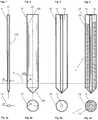
- Figure 1shows a primary preform 11 having a first primary axis x1, an outer diameter d1 and an outer surface 111. Manufacturing of such a preform has been described above.
- Figure 2shows a thin-walled silica tube 12, having a first primary axis x2, an inner diameter d2, an outer diameter d20 and an inner surface 120.
- the thin-walled silica tube 12, which comprises a conical closure 125 at its lower end,is used according to the inventive method as overcladding tube 12.
- Silica tubes of this kindare available from several manufacturers.
- Figure 3shows the primary preform 11 held in a centrally inserted position within the overcladding tube 12 with said first and second primary axes x1, x2 in substantial alignment with each other.
- the diameter d20 of the circular wall of the overcladding tube 12is for example ten times smaller than its inner diameter d2. However the ratio of said diameters d2/d20 may be up to 50 and higher.
- the ratio d2/d1 of the inner diameter d2 of the overcladding tube 12 and the outer diameter d1 of the primary preform 11is for example in the range of 1.5 up to 5 and more.
- the volume of the interior space 15, that is defined by the outer surface 111 of the primary preform 11 and inner surface 120 of the overcladding tube 12is relatively large, i.e. several times larger than the volume of the primary preform 11.
- Figure 4shows an unprocessed secondary preform 1 with the primary preform 11 and the overcladding tube 12 of figure 3 with the interior space 15 filled with overcladding grain 13, a pure or doped synthetic silica grain or powder, that is selected according to the desired properties of the fibre during the drawing process or in view of its later performance.
- Figures 1a, 2a, 3a and 4ashow cross-sections of the primary preform 11, the overcladding tube 12 and the overcladding grain 13 along line s in figures 1 to 4 .
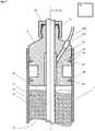
- Figure 5shows the secondary preform 1 of figure 4 with an adjoiner 3 inserted into the overcladding tube 12, holding the primary preform 11 in centralised position and closing and sealing the interior space 1 on the upper side.
- the overcladding grain 13had been inserted into the interior space 15 before the adjoiner 3 has been mounted.
- Figure 6shows the primary preform 11 and the overcladding tube 12 aligned and covered by means of an adjoiner 3, that comprises a channel 38, through which the overcladding grain 13 can be inserted.
- the adjoiners 3 shown in figures 5 and 6which have a first primary axis x3, further comprise evacuation channels 32, 33 through which, by means of a vacuum pump 22, the secondary preform 1, that is filled with overcladding grain 13, can be evacuated.
- Figures 5 and 6further show a heat supply or furnace 23, which allows heating of the secondary preform 1 at its lower end for example to temperatures in the range of to 2100 °C to 2350 °C. Due to the thermal energy provided by the furnace 23 and due to the established difference of pressures that are present in and outside the secondary preform 1, the overcladding tube 12 will collapse and press the molten overcladding grain 13 onto the primary preform 11. Thus, the overcladding material of the overcladding tube 12 and the overcladding grain 13 will form a practically homogeneous layer that adjoins the primary preform.
- Figures 5a and 6asymbolically show a cross-section of the secondary preform 1 after performing the melting process.
- Fusing of the secondary preform 1 and fibre drawingcan be performed simultaneously. However it is also possible to process the secondary preform 1 completely before the fibre is drawn.
- Figure 6shows in a sectional view of the upper end of secondary preform 1 of figure 5 in detail.
- the adjoiner 3, which is inserted into the overcladding tube 12,comprises two peripheral circular grooves with sealing elements, e.g. o-rings, that tightly adjoin and seal the inner surface 120 of the overcladding tube 12 so that the interior space 15 that is limited by the adjoiner 3, the outer surface 111 of the primary preform 11 and the inner surface 120 of the overcladding tube 12 and its closure 125 at the lower end can be evacuated.
- the evacuationcan be performed through evacuation channels 32 and 33 provided in the adjoiner 3 and through a tube 220 that connects the adjoiner 3 with the vacuum pump 22.
- the tube 220is connected to the adjoiner 3 by means of a valve 221 that can be closed after the evacuation process has been performed. Instead, for generating a condition of reduced pressure, a gas could be supplied to a corresponding channel in the adjoiner 3, as described in [2].
- the adjoiner 3 shown in figures 7 to 9further comprises, coaxially aligned with the first primary axis x3, a cylindrical opening 31 with a diameter d3 that corresponds to the outer diameter d1 of the primary preform 11 and, coaxially aligned with the first primary axis x3, two cylindrical segments 35 with a diameter d4 that corresponds to the inner diameter d2 of the overcladding tube 12.
- the adjoiner 3can therefore be inserted into the cladding tube 12 so that the cylindrical segments 35 adjoin the inner surface 120 of the overcladding tube 12 and the primary preform 11 is inserted into the cylindrical opening 31 which leads to an end piece 36 that either is closed or can be closed by means of a sealing cap 39.
- two grooves, adjoining the cylindrical segments 35,are provided, in which sealing elements 91 are inserted.
- Figure 8shows the adjoiner 3 used for the secondary preform 1 of figure 4 and figure 9 shows a sectional view of the adjoiner 3 of figure 7 , with the channel 38 provided for the insertion of overcladding grain 13.
- the first evacuation channel 32is arranged concentrically to the primary axis x3 of the adjoiner 3 with a diameter d5 that is significantly larger than the diameter d3 of the adjoining cylindrical opening 31.
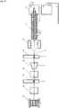
- Figure 10shows an apparatus used for drawing an optical fibre 5 from the secondary preform 1 of figure 5 .
- the optical fibre 25then eventually encounters a series of rollers (not shown) pulling the fibre before the optical fibre is then wrapped around a drum or spool 29.
- the secondary preform 1is mounted in a holding device 21, which allows controlled vertical movement along and preferably rotation around its axis x123. Furthermore the holding device 21 may be designed to apply a vibration onto the secondary preform in order to condense the overcladding grain 13 provided in the interior space 15.
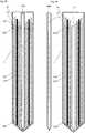
- Figure 11shows tubular and solid elongated structural elements 1201, 1201' being arranged in a two-dimensional periodic structure within an overcladding tube 12 that is filled with overcladding grain 13 in order to create a preform 1 designed for drawing Photonic Crystal Fibres.
- the two-dimensional periodic structureis selected to apply the photonic band gap (PBG) effect in the Photonic Crystal Fibre drawn from the preform 1.
- PBGphotonic band gap
- the definition of the two-dimensional periodic structureis not subject of the present Application. Publications describing these structures have been cited above. However with the present invention, preforms with all kinds of structures can easily and with low costs be realised, since the interior space between the elongated structural elements 1201, 1201' and the overcladding tube 12 is filled with a flexible medium, namely grain 13.
- relatively thin walled tubespreferably of a standard size, can be selected as elongated structural elements 1201, that will not be deformed or collapse during the heating process.
- removable rods 1205'which are removed after the heating process, can be used to keep the interior of the tubular elongated structural elements 1201 in correct shape.
- a removable rod 1205can be used without a tubular elongated structural element to keep an elongated empty space or void, i.e. free from overcladding material 13, 130. After the preform 1 is processed the removable rod 1205 is removed.
- a removable rod 1205is used as a space holder for the empty or gas filled core in which the light will be guided.
- the two-dimensional periodic structure applied in the preform 1 of figure 11comprises six overlapping cells, each comprising six peripheral and one central elongated structural element 1201, 1201.
- the peripheral elements 1201are tubular intended for crating elongated voids and the central elements 1201' are solid or full-bodied cylinders of a material with a refractive index that differs from the refractive index of the cladding material.
- Figure 12shows the heat-processed preform 1 of figure 11 inserted into a further overcladding tube 12' that is filled with overcladding grain 13 in order to create a larger preform 1.
- This methodnot only primary PCF-preforms, but secondary and ternary performs, etc., can easily be produced. This is based on the fact that the two-dimensional periodic structure does not need to extend over the complete cross section of the preform or the Photonic Crystal Fibre respectively.
- the preform 1represents a primary preform and is processed as described above (see figures 1-4 ).
- Figure 13shows the arrangement of figure 13 from the top with solid and peripherally molten tubular elements 1201, 1201'.
- the removable rod 1205 in the core region and removable rods 1205' in the tubular elements 1201have been removed leaving a hollow core and elongated side voids. Since the invention can be applied with any two-dimensional periodic structure additional secondary structural elements 1202 were added to the preform 1 as an example.
- Figure 14shows a glass matrix 200 that has been designed to receive and hold the structural elements 1201, 1201', 1202, 1205, 1205' in a two-dimensional periodic structure.
- the glass matrix 200which has the form of a disc or wafer, comprises openings 201, 202 through which the structural elements 1201, 1201' can be inserted. Further openings 203 are provided through which the grain 1 can be passed through. With these matrices 200 the preforms can easily be assembled. If the matrices 200 consist of cladding material 13, then the matrices 200 will be transformed during the heat-processing into a section of the cladding layer in the same way as the grain 13 is.
- matrices 200can be done with minimal effort.
- Figure 15shows a sectional view of a preform 1 with two inserted matrices 200 that hold tubular and solid elongated structural elements 1201, 1201' and a centralised removable rod 1205 arranged in a two-dimensional periodic structure within the overcladding tube 12, before heat-processing.
- Figure 16shows the preform 1 of figure 15 after heat-processing and removal of the removable rod 1205 that occupied the hollow core 11' of the preform 1.
- a solid rod 1201'can be provided that represents a solid core 11.
- a tubular structural element 1201 preferably filled with a removable rod 1205', a centralised solid rod 1201', or a centralised removable rod 1205serve as a replacement for the primary preform 11 shown in figure 1 .
- Figure 17shows an apparatus used for drawing a Photonic Crystal Fibre 5 from the preform 1 of figure 16 .
- Dimensions of the primary preform 11 and the overcladding tube 12 or the elongated structural elements 1201, 1201', 1202, 1205, 1205'can be selected in a wide range as well as the granularity of the overcladding grain or powder 13 and the refractive indices and dopants of the used materials.
- the diameter of the filled or empty core element 11, 11'is typically a multiple of the diameter of the remaining structural elements 1201, 1201', 1202.
- the removable rods 1205, 1205'are selected with a suitable thermal expansion so that they can easily be removed, when the preform is cooled down.
- the removable rods 1205, 1205'may for example consist of graphite.
- removing rods or canes from vitrified silicacan easily be done if a material with a thermal expansion coefficient is used, which is larger than the thermal expansion coefficient of glass.
- a material with a thermal expansion coefficiente.g. a graphite rod will retract or shrink stronger than glass so that will no adhesion remain to the glass.
- preforms with complex structurescomprising numerous elongated void elements can easily be created.
- structural elements 1210may be used that are covered or sealed thus preventing the overcladding grain 13 from entering.
- the structural elements 1210may be covered by a cap or sealed by means of a glass layer, which for example can be molten, after the overcladding grain 13 has been added.
- Materialsare selected according to the manufacturing parameters and properties desired for the fabricated optical fibre.
- the channels and openings 31, 32, 33, 38 and sealing means 34, 39, 91 for the adjoiner 3can be designed in various ways.
- the closure 125 at the lower end of the overcladding tube 12can have forms that significantly differ from a conical form.
- closure 125 and the lower end of the primary preformare preferably matched in order to facilitate alignment.
- Conditions for drawing a fibrecan be applied and optimised in a known manner (see e.g. [5], EP 1 384 700 A1 ), so that optimal operating parameters, such as furnace temperature and drawing speed, can be found.
- optimal operating parameterssuch as furnace temperature and drawing speed, can be found.
- operating parametersare not limited by values mentioned above.
Landscapes
- Chemical & Material Sciences (AREA)
- Engineering & Computer Science (AREA)
- Materials Engineering (AREA)
- Geochemistry & Mineralogy (AREA)
- Manufacturing & Machinery (AREA)
- General Life Sciences & Earth Sciences (AREA)
- Life Sciences & Earth Sciences (AREA)
- Organic Chemistry (AREA)
- Physics & Mathematics (AREA)
- General Physics & Mathematics (AREA)
- Optics & Photonics (AREA)
- Manufacture, Treatment Of Glass Fibers (AREA)
- Optical Fibers, Optical Fiber Cores, And Optical Fiber Bundles (AREA)
- Glass Compositions (AREA)
- Chemical Or Physical Treatment Of Fibers (AREA)
Abstract
Description
- The present invention relates to a method and to a preform used for fabricating a photonic crystal fibre. Fabrication of optical fibres, such as the fibres currently used in ultra high speed data communication networks, is described in [1],Mool C. Gupta, Handbook of PHOTONICS, CRC Press, 1997 Boca Raton, chapter 10.7, pages 445-449. Main process steps of optical fibre fabrication are fabricating a glass blank (below called preform), drawing the fibre from the preform and coating the fibre with a material that protects the fibre from handling and from environmental influences. According to [1], there are basically three methods to form the preform. The modified chemical vapor deposition process (MCVD), the outside vapour deposition process (OVD) and the vapour-axial deposition process (VAD).
- In the drawing process, the preform is fed from above into the drawing portion of the furnace while being drawn from the bottom using tractors. The fibre is then wound onto a drum while being monitored for tensile strength. The temperature during draw is on the border of 2000°C. After exiting the furnace the fibre is coated with a UV-curable coating before winding on the drum.
- As described in [2],
U.S. 6,519,974 B1 , the MCVD method has certain advantages over the other methods. In the MCVD process, successive layer of SiO2 and dopants, which include germania, phosphorous and fluorine, are deposited on the inside of a fused silica tube by mixing the chloride vapors and oxygen at a temperature in the order of 1800°C. In the layer deposition process the cladding layers are laid down first, and then the layers that will form the core are deposited. After deposition of the layers, the internally-layered quartz tube is heated in the presence of Cl2 and He so as to form a compact quartz rod. - As further stated in [2], the MCVD method, used by itself, has the inherent limitation that it is not suitable to make preforms of more than 25 mm in diameter. In order to overcome this limitation, MCVD is often practiced with a so-called overcladding method, which allows fabrication of relatively large preforms and thus improves productivity for the fibre fabrication process. Conventional overcladding involves, in general terms, placing a rod preform inside a tube made of a suitable overcladding material, fusing the rod and tube together to form a secondary preform, and drawing from the secondary preform an optical fibre comprising a core enclosed within a cladding layer. Thus, a high-productivity implementation of the MCVD method requires three essential steps: preparing a primary optical fibre preform by internal deposition, overcladding the primary optical fibre preform to obtain a secondary optical fibre preform, and finally drawing an optical fibre from the secondary optical fibre preform.
- In [2], it has been found that carrying out these three steps separately requires
- a) substantial amounts of time and consequently has a negative effect on productivity;
- b) a large amount of oxygen or hydrogen for the step of overcladding the primary optical fibre preform; and
- c) application of a relatively large amount of heat for the overcladding step, if the primary optical fibre preform is relatively large.
- To overcome these disadvantages a combination of the overcladding and drawing steps was proposed e.g. in [3],
U.S. Pat. No. 2,980,957 . The method disclosed in [3] comprises the steps of creating between a core rod and a thereto concentrically arranged overcladding tube a high vacuum prior to the drawing stage and further a controlled low vacuum in order to controllably counteract the drawing forces and cause the tubular member to progressively collapse into the space between the core rod and the overcladding tube. One problem in combining the fusing and drawing stages has been to control the application of vacuum with sufficient precision that the finished optical fibre has sufficient strength and optical quality for modern communications applications. - Another aspect addressed in [2] is the proper alignment of the core rod and the overcladding tube. A method has been disclosed in [4],
U.S. Pat. No. 4,820,322 , that allows the fabrication of a strong fibre with concentric core and cladding, that uses a vacuum to promote collapse of the overcladding tube, and that can be practiced either in a separate manufacturing phase or in a continuous process combined with drawing of the fibre. As stated in [2] the approach disclosed in [4] has a limit on the gap between the rod and the overcladding tube; the tube inside diameter cannot exceed the rod diameter by more than a certain amount. Furthermore, the embodiment combining collapsing the tube and drawing the fibre does not use an affirmative means to center the rod in the tube, relying instead for concentricity on inherent self-centering forces thought to be present as the fibre is drawn from the tip of the rod-and-tube preform. - To improve the techniques described above a method has been proposed in [2] that allows drawing of an optical fibre from a rod-and-tube preform while simultaneously fusing the rod and the overcladding tube. This rod-in-tube approach employs a low-intensity vacuum source that permits fine adjustment of the differential pressure. It also provides for controlled alignment of the core rod and the overcladding tube to ensure that the desired circumferential uniformity of the cladding layer in the drawn fibre is achieved. The low-intensity vacuum is achieved by introducing a flow of gas into an adjoiner that holds a primary optical fibre preform having a first primary axis and an outer surface and an overcladding tube having a second primary axis and an inner surface defining an interior space, coaxially aligned together as a secondary preform assembly. The flow of gas through a channel in the adjoiner generates a condition of reduced pressure in accordance with Bernoulli's theorem, and therefore partially evacuates the space between the overcladding tube and the primary optical fibre preform. The flow rate through channel will determine the extent to which the gas pressure in the space is reduced.
- According to [2], the main concern with the realisation of rod-in-tube processes is focussed on alignment procedures and the application of a precisely controlled vacuum. However, besides these known main concerns, costs for the production of high quality optical fibre from a rod-and-tube preform are a continuous concern.
- It would therefore be desirable to provide an improved method and an apparatus that allow fabricating high quality optical fibre from a rod-and-tube preform.
- It would be desirable in particular to provide a method that allows fabricating high quality optical fibre from a rod-and-tube preform at significantly reduced cost.
- Still further it would be desirable to provide a method that allows a reduction of the requirement of precision in alignment of rod and tube of the rod-and-tube preform as well as a reduction of the requirement of precision for controlling the vacuum for sequential or simultaneous preform fusing and fibre drawing.
[10],WO 03/093884 A2 - It would therefore be desirable to provide an improved method that allows fabricating high quality photonic crystal fibres from a rod-and-tube preform.
- It would be desirable in particular to provide a method that allows fabricating high quality photonic crystal fibres from a rod-and-tube preform at significantly reduced cost.
- It would further be desirable to create a rod-and-tube preform, that can be used with the inventive method, as well as high quality photonic crystal fibres drawn from said rod-and-tube preform.
- It would further be desirable to create a rod-and-tube preform that allows modification of the properties of the photonic crystal fibre drawn from said rod-and-tube preform with reduced effort.
- However besides traditional fibres which are derived from "single rod and single tube" preforms, so called Photonic Crystal Fibres (PCF) emerged in recent years which rely on a new mechanism for guiding light.
- As described in [8],
U.S. Patent 6,845,204 , traditional waveguides operate by guiding the electromagnetic field (the light or the photons) through a physical effect, which is known as total internal reflection. By using this fundamental effect, the propagation (or loss) of optical power in directions perpendicular to the waveguide axis is reduced. In order to obtain total internal reflection in these waveguides, which are often fabricated from dielectric materials (in optical fibres) or semiconductors (in integrated optics), it is necessary to use a higher refractive index of the core compared to the refractive index of the surrounding cladding. - During the past ten years, however, the development within the area of new materials has opened up the possibilities of localisation of light or control of electromagnetic fields in cavities or waveguides by applying the so-called photonic band gap (PBG) effect. The PBG effect may be introduced by providing a spatially periodic lattice structure, in which the lattice dimensions and applied materials are chosen in such a way that electromagnetic field propagation is inhibited within the gap in certain frequency intervals and in certain directions.
- By locally breaking the periodicity of a photonic crystal, a spatial region with optical properties different from the surrounding bulk photonic crystal can be created. If such a defect region supports modes with frequencies falling inside the forbidden gap of the surrounding full-periodic crystal, these modes will be strongly confined to the defect. This is the principle on which the operation of the PBG guiding fibres relies, namely a complete out-of-plane 2D band gap exhibited by the photonic crystal cladding, and a correctly designed defect, forming a spatial region to which very strong transverse confinement car be achieved. For this defect region to exhibit optical properties different from the surrounding periodic structure (i.e., be able to support a localised mode) it is important to notice that it is not a requirement that the defect region, normally the core of the Photonic Crystal Fibre, has a higher index than its surroundings. Hence Photonic Crystal Fibres may comprise a hollow core or a solid core.
- Compared to traditional fibres, Photonic Crystal Fibres comprise a complex structure. Photonic Crystal Fibres typically have a core region extending along the longitudinal direction, a cladding region extending along the longitudinal direction, said cladding region comprising an at least substantially two-dimensionally periodic structure comprising primary, elongated elements each having a centre axis extending in the longitudinal direction of the waveguide. The primary elements having a refractive index being lower than a refractive index of any material adjacent to the elongated elements.
- Hence, the cladding forms a dielectric confinement region surrounding the core about the waveguide axis. Based on the band gap-effect, the confinement region guides electromagnetic radiation in at least a first range of frequencies along the waveguide axis. Thus, the light is trapped in the core, not by total reflection, but by the band gap-effect exhibited by the cladding that acts like an insulator for the light.
- The periodic structure, that contains at least one sort of elongated structural elements, may be defined in various ways in order to obtain a desired band gap or a plurality of band gaps with a desired dimension.
- Geometrical forms and sizes as well as refractive indexes of primary, secondary or further elongated elements typically differ from one another.
- Further, according to [9],
U.S. Patent 6,625,364 , it has been recognized that designing a photonic crystal fibre with a large core radius (e.g., larger than about twice the wavelength of the guided radiation) leads to many desirable properties. For example, the fraction of energy outside of the core for a guided mode in a photonic crystal fibre scales inversely with the cube of the core radius. Accordingly, radiation and dissipation losses associated with the dielectric confinement layers can be made very small by increasing the core radius. Moreover, because the confinement mechanism is not based on total internal reflection (TIR), the core material is not limited to a material having a relatively high index. Thus, the core material can be selected to minimize losses and nonlinearities. For example, the fibre may have a hollow core. Furthermore, confinement in the core is further improved by selecting materials for the layers (or regions) outside the core to have a large contrast in refractive index. Such contrasts are possible because the large core radius makes dissipation by the outside layers (or regions) less of an issue and thus the constituent materials of the outside layers (or regions) can be selected more on the basis of providing the desired index contrast, than on absorption losses. - As a consequence, for a manufacturer, it is important that preforms with complex structures can be set up and produced with minimal efforts and cost; bearing in mind that a further optimised structure or even a multi core structure could be proposed next day.
- Still further, particularly for complex structures it is important that undesired voids are avoided (see [10],
U.S. Patent 6,698,249 ) while desired elongated voids are precisely realised, in order to avoid bandgap gradients. - Today, some preforms are made by stacking hundreds of capillary tubes and rods by hand into a structure with the appropriate pattern of holes. A hollow core is made by replacing one or more of the capillary tubes by a hollow tube with a significantly larger diameter. This preform is then introduced into the furnace of a fibre drawing tower where it is fused together and drawn to a size of 1-10 mm. Then a sleeve tube is added before it is drawn into the final dimensions. With this method, which is applied by Crystal Fibre A/S, the production of larger preforms involves considerable efforts.
- Since the PBG-effect, which is the fundamental element of the low-index guiding property, is obtained by the periodicity of the cladding structure, only a very limited number of periods is necessary in order to confine the electromagnetic field, and it will, according to [8], be possible to use conventional overcladding of the part of the preform that contains the periodicity. Hence known overcladding techniques, e.g. said sleeving, can be applied.
- As an alternative to the conventional overcladding approach, in [8] another approach is suggested, in which the fibre surrounding core area is constructed by bundling capillary tubes into a close-packed arrangement according to the preferred design of the periodic cladding region. Outside of this periodic region with the capillary tubes, which have to be fixed in position, the outer fibre structure (corresponding to an outer cladding region) could be formed by packing of thinner glass rods, which could be mechanically shaken into place. When the preform then later is drawn into a fibre, the outer cladding structure is melted together to form a (near) solid outer cladding. The requirement for the outside placement of thin glass rods is that the surface tension due to an uneven distribution outside the periodic part of the fibre, do not result in a significant deformation of the periodicity. However in view of the complex structures mechanically shaking the fine capillary tubes involves the risks of cracking tubes, leaving voids open or disturbing the periodic structure.
- Since Photonic Crystal Fibres with new functionalities may be fabricated by introducing regions within the fibres with special doping materials, or even materials that deviates significantly from the fibre basis material (e.g., glass, or polymers); the fabrication process may comprise the introduction of thin rods of doped (or different) material at well-defined locations in the closely packed, periodic basis material structure. Alternatively, some of the capillary tubes could be made from a doped material, or the preform (or parts of it) could even be placed in solutions of materials that could diffuse or bind to the basis material rods and tubes. Since specific parts of the preform could be treated individually before further stacking or alternative processing would continue, this approach allows for a very high degree of flexibility.
- It would therefore further be desirable to provide an improved method that allows fabricating high quality Photonic Crystal Fibres from a corresponding preform.
- Further, it would be desirable to provide a method that facilitates production of preforms for Photonic Crystal Fibres and that allows production of larger preforms.
- It would be desirable in particular to provide a method that allows realising complex structures accurately with tubes and rods that can be selected for optimal performance of the produced Photonic Crystal Fibres, while neglecting geometrical dimensions that were essential with known methods for obtaining the desired periodical structures.
- Still further it would be desirable to provide a method that allows independent selection and placement of structural elements.
- It would further be desirable to create preforms, that can be used with the inventive method in order to draw high quality Photonic Crystal Fibres.
- The above and other objects of the present invention are achieved by a method according to
claim 1 and a preform according toclaim 11. - The method for fabricating a photonic crystal fibre according to
claim 1 comprises the steps of: - creating a preform by
- inserting elongated structural elements such as rods and/or tubes, having first primary axes and outer surfaces and being arranged in an at least substantially two-dimensionally periodic structure, into an overcladding tube having a second primary axis and an inner surface, said outer surfaces and inner surface defining an interior space;
- holding the structural elements with the first primary axes in parallel to the second primary axis of the overcladding tube;
- supplying overcladding grain into the interior space that is limited at the lower end of the overcladding tube by means of a closure; and
- generating a condition of reduced pressure within the interior space that is limited at the upper end of the overcladding tube preferably by means of an adjoiner; and then
- heating, by a furnace, the produced preform, with the structural elements, the overcladding tube and the overcladding grain, at its lower end to a softened state and simultaneously drawing an optical fibre therefrom, or
- heating, by a furnace, the produced preform, with the structural elements, the overcladding tube and the overcladding grain, over its entire length in order to obtain a processed preform,
- and drawing an optical fibre in a subsequent process stage. The preform according to
claim 11, which is used for manufacturing Photonic Crystal Fibers produced with the method according toclaim 1 comprises - elongated structural elements such as rods and/or tubes, having first primary axes and outer surfaces and being arranged in an at least substantially two-dimensionally periodic structure, provided in an overcladding tube having a second primary axis and an inner surface, said outer surfaces and inner surface defining an interior space;
- the structural elements being held with the first primary axes in parallel to the second primary axis of the overcladding tube;
- overcladding grain provided in the interior space that is limited at the lower end of the overcladding tube by means of a closure; and
- the assembled preform having been thermally processed over its entire length.
- Due to the thermal energy provided by the furnace and due to the established difference of pressures that are present in and outside the preform, the overcladding tube will collapse and press the molten overcladding grain onto the primary preform or the structural elements.
- The overcladding material of the overcladding tube and the overcladding grain will form a practically homogeneous layer that adjoins the primary preform in the same manner as the thick overcladding tube does, when it collapses, in conventional rod-and-tube applications, as described for example in [2].
- Fusing of the secondary preform and fibre drawing can be performed simultaneously as with the method described in [2]. However the unprocessed secondary preform can also be processed in a preliminary process stage in order to obtain a processed secondary preform from which an optical fibre can be drawn in a subsequent process stage at the present or another process site.
- The present invention however yields numerous advantages over the prior art mentioned above:
- The known method of producing a secondary preform by sleeving an overcladding tube with thick walls over a primary preform is abandoned. Instead an overcladding tube with thin walls is used and the interior space between the primary preform and the inner surface of the overcladding tube is filled with silica grain. Consequently the effort and costs for the production of the overcladding preform with thick walls are avoided. Instead of a costly silica tube with thick walls, silica grain can be used.
- Due to the mobility of the overcladding grain, the interior space or gap between the outer surface of the primary preform and the inner surface of the overcladding tube is evenly filled with the silica grain, so that a misalignment between the primary preform and the overcladding tube. Besides the elimination of alignment problems the control of the pressure reduction is less critical, since the overcladding tube is not collapsing uncontrolled into a free gap but pressing steadily onto the supporting grain.
- The inner diameter of the thin-walled overcladding tube is preferably selected at least 1.5 times larger than the outer diameter of the primary preform and more than 10 times larger than its wall diameter. However, in practice any dimensions can be realised, that are supported by the mechanical strength of the related elements.
- Further the overcladding tube is preferably supplied with a conically formed closure at its lower end, so that the walls of the overcladding tube and the primary preform meet at their lower end and silica grain can be filled into the interior space. Since the primary preform in a preferred embodiment also comprises a conical form at its lower end, the alignment procedures are significantly facilitated.
- The overcladding grain, which consists of particles with a small diameter, e.g. a powder, is inserted into the interior space before the adjoiner is mounted or after the adjoiner is mounted, through a channel provided therein.
- The overcladding grain may be a pure or doped synthetic silica powder that may be selected according to the desired properties of the fabricated fibre. A method of manufacturing a silica powder using a sol-gel technique is described in [6],
U.S. Patent 6'047,568 . Further sol-gel techniques, for achieving higher drawing forces and reducing breakage risks during the drawing process are described in [7],U.S. Patent 6'334'338 . Hence the inventive method also provides a high flexibility that allows meeting the customer's demands within short notice. - Also in view of the production of Photonic Crystal Fibres the present invention yields significant improvements over the prior art.
- Since the axes of the elongated structural elements, whose ends form the two-dimensional periodic structure, may be relatively far apart, large spatial gaps can be filled cost efficiently with grain, thereby avoiding thick walled tubular structural elements.
- Further, for all two-dimensional periodic structures that relate to a desired band gap, identical structural elements may be applied.
- Alignment and holding of elongated structural elements or a primary preform can easily be achieved by using a matrix with openings corresponding to the two-dimensional periodic structure. The elongated structural elements or the primary preform are inserted for example into two matrices that fix the elongated structural elements or the primary preform at both ends. Hence, the complete structure can easily be assembled and inserted into an overcladding tube.
- Each matrix is preferably formed as a disk that may be held at defined positions within the overcladding tube, e.g. by means of inner flanges.
- Further each matrix preferably comprises openings that allow transferring of the grain.
- The matrix is preferably made of material that corresponds to the grain so that it will melt together with the overcladding material.
- In order to close gaps and holes and to obtain a higher material density a vibration, preferably a high frequency vibration may be applied.
- Structural elements may be tubes and rods or tube-and-rod combinations. Tubes may be used if a void shall be created that corresponds to the inner space of the tube. Solid rods may be used with a selected refractive index in order to create corresponding solid lines in the fibres. However rods may also be removed during or after the heating process stepwise or completely after the grain is molten in order to create an elongated void, which is also a structural element in the preform and the fibre. Using removable rods, which are removed, prevents the structural elements from collapsing during the heating process.
- In order to prevent collapsing a coolant may also be transferred through the tubular structural elements during the process of melting the grain. Prevention of collapsing may also be achieved by exposing the interior of the tubular structural elements to a pressure during the process of melting the grain.
- Some of the objects and advantages of the present invention have been stated, others will appear when the following description is considered together with the accompanying drawings, in which:
- Figure 1
- shows a
primary preform 11 having a first primary axis x1; - Figure 2
- shows a thin-
walled silica tube 12, having a first primary axis x2, with aconical closure 125 at its lower end that, according to the inventive method, is used asovercladding tube 12; - Figure 3
- shows the
primary preform 11 held in a centrally inserted position within theovercladding tube 12 with said first and second primary axes x1, x2 in substantial alignment with each other; - Figure 4
- shows an unprocessed
secondary preform 1 with theprimary preform 11 and theovercladding tube 12 offigure 3 with aninterior space 15, that is defined by the outer surface 111 of theprimary preform 11 andinner surface 120 of theovercladding tube 12, filled withovercladding grain 13; - Figure 5
- shows the
secondary preform 1 offigure 4 with anadjoiner 3 partially inserted into theovercladding tube 12, holding theprimary preform 11 in centralised position and closing and sealing theinterior space 1 on its upper side; - Figure 6
- shows a
secondary preform 1 with anadjoiner 3 that allows insertion ofovercladding grain 13 through achannel 38; - Figure 7
- shows the upper end of
secondary preform 1 offigure 5 in detail; - Figure 8
- shows the
adjoiner 3 used for thesecondary preform 1 offigure 4 ; - Figure 9
- shows a sectional view of the
adjoiner 3 offigure 6 , with thechannel 38 provided for the insertion ofovercladding grain 13; - Figure 10
- shows an apparatus used for drawing an optical fibre from the
secondary preform 1 offigure 5 ; - Figure 11
- shows tubular and solid elongated
structural elements 1201, 1201' being arranged in a two-dimensional periodic structure within anovercladding tube 12 that is filled withovercladding grain 13 in order to create apreform 1 designed for drawing Photonic Crystal Fibres; - Figure 12
- shows the heat-processed
preform 1 offigure 11 inserted into a further overcladding tube 12' that is filled withovercladding grain 13 in order to create alarger preform 1; - Figure 13
- shows the arrangement of
figure 13 from the top; - Figure 14
- shows a
glass matrix 200 designed to receive and hold thestructural elements 1201, 1201' in a two-dimensional periodic structure; - Figure 15
- shows a sectional view of a
preform 1 with two insertedmatrices 200 that hold tubular and solid elongatedstructural elements 1201, 1201' and a centralisedremovable rod 1205 arranged in a two-dimensional periodic structure within theovercladding tube 12, before heat-processing; - Figure 16
- shows the
preform 1 offigure 15 after heat-processing and removal of theremovable rod 1205 that occupied the core 11' of the preform; and - Figure 17
- shows an apparatus used for drawing a Photonic Crystal Fibre from the
preform 1 offigure 16 . Figure 1 shows aprimary preform 11 having a first primary axis x1, an outer diameter d1 and an outer surface 111. Manufacturing of such a preform has been described above.Figure 2 shows a thin-walled silica tube 12, having a first primary axis x2, an inner diameter d2, an outer diameter d20 and aninner surface 120. The thin-walled silica tube 12, which comprises aconical closure 125 at its lower end, is used according to the inventive method asovercladding tube 12. Silica tubes of this kind are available from several manufacturers.Figure 3 shows theprimary preform 11 held in a centrally inserted position within theovercladding tube 12 with said first and second primary axes x1, x2 in substantial alignment with each other.- The diameter d20 of the circular wall of the
overcladding tube 12 is for example ten times smaller than its inner diameter d2. However the ratio of said diameters d2/d20 may be up to 50 and higher. The ratio d2/d1 of the inner diameter d2 of theovercladding tube 12 and the outer diameter d1 of theprimary preform 11 is for example in the range of 1.5 up to 5 and more. - Hence, the volume of the
interior space 15, that is defined by the outer surface 111 of theprimary preform 11 andinner surface 120 of theovercladding tube 12 is relatively large, i.e. several times larger than the volume of theprimary preform 11. Figure 4 shows an unprocessedsecondary preform 1 with theprimary preform 11 and theovercladding tube 12 offigure 3 with theinterior space 15 filled withovercladding grain 13, a pure or doped synthetic silica grain or powder, that is selected according to the desired properties of the fibre during the drawing process or in view of its later performance.Figures 1a, 2a, 3a and 4a show cross-sections of theprimary preform 11, theovercladding tube 12 and theovercladding grain 13 along line s infigures 1 to 4 .Figure 5 shows thesecondary preform 1 offigure 4 with anadjoiner 3 inserted into theovercladding tube 12, holding theprimary preform 11 in centralised position and closing and sealing theinterior space 1 on the upper side. In this embodiment of the invention theovercladding grain 13 had been inserted into theinterior space 15 before theadjoiner 3 has been mounted.Figure 6 shows theprimary preform 11 and theovercladding tube 12 aligned and covered by means of anadjoiner 3, that comprises achannel 38, through which theovercladding grain 13 can be inserted.- The
adjoiners 3 shown infigures 5 and 6 , which have a first primary axis x3, further compriseevacuation channels vacuum pump 22, thesecondary preform 1, that is filled withovercladding grain 13, can be evacuated. Figures 5 and 6 further show a heat supply orfurnace 23, which allows heating of thesecondary preform 1 at its lower end for example to temperatures in the range of to 2100 °C to 2350 °C. Due to the thermal energy provided by thefurnace 23 and due to the established difference of pressures that are present in and outside thesecondary preform 1, theovercladding tube 12 will collapse and press themolten overcladding grain 13 onto theprimary preform 11. Thus, the overcladding material of theovercladding tube 12 and theovercladding grain 13 will form a practically homogeneous layer that adjoins the primary preform.Figures 5a and 6a symbolically show a cross-section of thesecondary preform 1 after performing the melting process.- Fusing of the
secondary preform 1 and fibre drawing can be performed simultaneously. However it is also possible to process thesecondary preform 1 completely before the fibre is drawn. Figure 6 shows in a sectional view of the upper end ofsecondary preform 1 offigure 5 in detail. Theadjoiner 3, which is inserted into theovercladding tube 12, comprises two peripheral circular grooves with sealing elements, e.g. o-rings, that tightly adjoin and seal theinner surface 120 of theovercladding tube 12 so that theinterior space 15 that is limited by theadjoiner 3, the outer surface 111 of theprimary preform 11 and theinner surface 120 of theovercladding tube 12 and itsclosure 125 at the lower end can be evacuated. The evacuation can be performed throughevacuation channels adjoiner 3 and through atube 220 that connects theadjoiner 3 with thevacuum pump 22. Thetube 220 is connected to theadjoiner 3 by means of avalve 221 that can be closed after the evacuation process has been performed. Instead, for generating a condition of reduced pressure, a gas could be supplied to a corresponding channel in theadjoiner 3, as described in [2].- The
adjoiner 3 shown infigures 7 to 9 further comprises, coaxially aligned with the first primary axis x3, acylindrical opening 31 with a diameter d3 that corresponds to the outer diameter d1 of theprimary preform 11 and, coaxially aligned with the first primary axis x3, twocylindrical segments 35 with a diameter d4 that corresponds to the inner diameter d2 of theovercladding tube 12. Theadjoiner 3 can therefore be inserted into thecladding tube 12 so that thecylindrical segments 35 adjoin theinner surface 120 of theovercladding tube 12 and theprimary preform 11 is inserted into thecylindrical opening 31 which leads to anend piece 36 that either is closed or can be closed by means of a sealingcap 39. - For sealing the adjoiner towards the
inner surface 120 of theovercladding tube 12, two grooves, adjoining thecylindrical segments 35, are provided, in which sealingelements 91 are inserted. Figure 8 shows theadjoiner 3 used for thesecondary preform 1 offigure 4 andfigure 9 shows a sectional view of theadjoiner 3 offigure 7 , with thechannel 38 provided for the insertion ofovercladding grain 13. Infigure 9 it is further shown that thefirst evacuation channel 32 is arranged concentrically to the primary axis x3 of theadjoiner 3 with a diameter d5 that is significantly larger than the diameter d3 of the adjoiningcylindrical opening 31.Figure 10 shows an apparatus used for drawing anoptical fibre 5 from thesecondary preform 1 offigure 5 . Once thesecondary preform 1 is heated to its melting point and afibre 5 has been pulled, an angular area called the neck-down is formed. A singleoptical fibre 5 emerges from the preform in a semi-molten state and passes through adiameter monitor 24. Theoptical fibre 5 continues to be pulled downward and passes through acoating applicator 25 that applies a coating to protect theoptical fibre 5. Theoptical fibre 5 also passes throughother units optical fibre 5 then encounters aspinning apparatus 28 which may comprise a roller that imparts a spin into the optical fibre. Theoptical fibre 25 then eventually encounters a series of rollers (not shown) pulling the fibre before the optical fibre is then wrapped around a drum orspool 29. Thesecondary preform 1 is mounted in a holdingdevice 21, which allows controlled vertical movement along and preferably rotation around its axis x123. Furthermore the holdingdevice 21 may be designed to apply a vibration onto the secondary preform in order to condense theovercladding grain 13 provided in theinterior space 15.Figure 11 shows tubular and solid elongatedstructural elements 1201, 1201' being arranged in a two-dimensional periodic structure within anovercladding tube 12 that is filled withovercladding grain 13 in order to create apreform 1 designed for drawing Photonic Crystal Fibres. The two-dimensional periodic structure is selected to apply the photonic band gap (PBG) effect in the Photonic Crystal Fibre drawn from thepreform 1. The definition of the two-dimensional periodic structure is not subject of the present Application. Publications describing these structures have been cited above. However with the present invention, preforms with all kinds of structures can easily and with low costs be realised, since the interior space between the elongatedstructural elements 1201, 1201' and theovercladding tube 12 is filled with a flexible medium, namelygrain 13.- As a consequence relatively thin walled tubes, preferably of a standard size, can be selected as elongated
structural elements 1201, that will not be deformed or collapse during the heating process. However, as shown infigure 11 , removable rods 1205', which are removed after the heating process, can be used to keep the interior of the tubular elongatedstructural elements 1201 in correct shape. Further, aremovable rod 1205 can be used without a tubular elongated structural element to keep an elongated empty space or void, i.e. free fromovercladding material preform 1 is processed theremovable rod 1205 is removed. Infigure 11 aremovable rod 1205 is used as a space holder for the empty or gas filled core in which the light will be guided. - The two-dimensional periodic structure applied in the
preform 1 offigure 11 comprises six overlapping cells, each comprising six peripheral and one central elongatedstructural element peripheral elements 1201 are tubular intended for crating elongated voids and the central elements 1201' are solid or full-bodied cylinders of a material with a refractive index that differs from the refractive index of the cladding material. Figure 12 shows the heat-processedpreform 1 offigure 11 inserted into a further overcladding tube 12' that is filled withovercladding grain 13 in order to create alarger preform 1. With this method not only primary PCF-preforms, but secondary and ternary performs, etc., can easily be produced. This is based on the fact that the two-dimensional periodic structure does not need to extend over the complete cross section of the preform or the Photonic Crystal Fibre respectively. Thepreform 1 represents a primary preform and is processed as described above (seefigures 1-4 ).Figure 13 shows the arrangement offigure 13 from the top with solid and peripherally moltentubular elements 1201, 1201'. Theremovable rod 1205 in the core region and removable rods 1205' in thetubular elements 1201 have been removed leaving a hollow core and elongated side voids. Since the invention can be applied with any two-dimensional periodic structure additional secondarystructural elements 1202 were added to thepreform 1 as an example.Figure 14 shows aglass matrix 200 that has been designed to receive and hold thestructural elements glass matrix 200, which has the form of a disc or wafer, comprisesopenings structural elements 1201, 1201' can be inserted.Further openings 203 are provided through which thegrain 1 can be passed through. With thesematrices 200 the preforms can easily be assembled. If thematrices 200 consist ofcladding material 13, then thematrices 200 will be transformed during the heat-processing into a section of the cladding layer in the same way as thegrain 13 is.- The production of
matrices 200, however, can be done with minimal effort. Figure 15 shows a sectional view of apreform 1 with two insertedmatrices 200 that hold tubular and solid elongatedstructural elements 1201, 1201' and a centralisedremovable rod 1205 arranged in a two-dimensional periodic structure within theovercladding tube 12, before heat-processing.Figure 16 shows thepreform 1 offigure 15 after heat-processing and removal of theremovable rod 1205 that occupied the hollow core 11' of thepreform 1. Instead of an empty core 11' a solid rod 1201' can be provided that represents asolid core 11. As a comparison, a tubularstructural element 1201 preferably filled with a removable rod 1205', a centralised solid rod 1201', or a centralisedremovable rod 1205 serve as a replacement for theprimary preform 11 shown infigure 1 .Figure 17 shows an apparatus used for drawing aPhotonic Crystal Fibre 5 from thepreform 1 offigure 16 .- Dimensions of the
primary preform 11 and theovercladding tube 12 or the elongatedstructural elements powder 13 and the refractive indices and dopants of the used materials. The diameter of the filled orempty core element 11, 11' is typically a multiple of the diameter of the remainingstructural elements removable rods 1205, 1205' are selected with a suitable thermal expansion so that they can easily be removed, when the preform is cooled down. Theremovable rods 1205, 1205' may for example consist of graphite. Hence, removing rods or canes from vitrified silica can easily be done if a material with a thermal expansion coefficient is used, which is larger than the thermal expansion coefficient of glass. During a cooling process e.g. a graphite rod will retract or shrink stronger than glass so that will no adhesion remain to the glass. Hence, with removable rods, preforms with complex structures comprising numerous elongated void elements can easily be created. - It is important to note that the forms dimensions of all structural elements are not limited to the examples defined above. Further, as shown in
figure 11 ,structural elements 1210 may be used that are covered or sealed thus preventing theovercladding grain 13 from entering. Thestructural elements 1210 may be covered by a cap or sealed by means of a glass layer, which for example can be molten, after theovercladding grain 13 has been added. Materials are selected according to the manufacturing parameters and properties desired for the fabricated optical fibre. The channels andopenings adjoiner 3 can be designed in various ways. Theclosure 125 at the lower end of theovercladding tube 12 can have forms that significantly differ from a conical form. However theclosure 125 and the lower end of the primary preform are preferably matched in order to facilitate alignment. Conditions for drawing a fibre can be applied and optimised in a known manner (see e.g. [5],EP 1 384 700 A1 - [1]Mool C. Gupta, Handbook of PHOTONICS, CRC Press, 1997 Boca Raton, chapter 10.7, pages 445-449
- [2]
U.S. 6,519,974 B1 - [3]
U.S. Pat. No. 2,980,957 - [4]
U.S. Pat. No. 4,820,322 - [5]
EP 1 384 700 A1 - [6]
U.S. Patent 6'047,568 - [7]
U.S. Patent 6'334'338 - [8]
U.S. Patent 6,845,204 - [9]
U.S. Patent 6,625,364 - [10]
U.S. Patent 6,698,249 WO 03/093884 A
Claims (14)
- Method for fabricating a Photonic Crystal Fibre, comprising the steps of
creating a preform (1) by
inserting elongated structural elements (11, 11'; 1201, 1202, ..., 120n) such as rods and/or tubes, having first primary axes (x1, x20) and outer surfaces (111') and being arranged in an at least substantially two-dimensionally periodic structure, into an overcladding tube (12) having a second primary axis (x2) and an inner surface (120), said outer surfaces (111') and inner surface (120) defining an interior space (15);
holding the structural elements (11, 11'; 1201, 1202, ..., 120n) with the first primary axes (x1, x20) in parallel to the second primary axis (x2) of the overcladding tube (12);
supplying overcladding grain (13) into the interior space (15) that is limited at the lower end of the overcladding tube (12) by means of a closure (125); and
generating a condition of reduced pressure within the interior space (15) that is limited at the upper end of the overcladding tube (12) preferably by means of an adjoiner (3); and then
heating, by a furnace (23), the produced preform (1), with the structural elements (11, 11'; 1201, 1202, ..., 120n), the overcladding tube (12) and the overcladding grain (13), at its lower end to a softened state and simultaneously drawing an optical fibre (5) therefrom, or
heating, by a furnace (23), the produced preform (1), with the structural elements (11, 11'; 1201, 1202, ..., 120n), the overcladding tube (12) and the overcladding grain (13), over its entire length in order to obtain a processed preform (1),
and drawing an optical fibre (5) in a subsequent process stage. - Method according to claim 1, wherein the overcladding tube (12) comprises a conically formed closure (125) and/or wherein the overcladding grain (13), which consists of particles with a small diameter, is inserted before the adjoiner (3) is mounted or after the adjoiner (3) is mounted, through a channel (38) provided therein.
- Method according to one of the claims 1 or 2, wherein the overcladding grain (13) is a pure or doped synthetic silica grain that is selected according to the desired properties of the fabricated fibre (5).
- Method according to one of the claims 1 to 3, wherein the temperature in the furnace (23) is selected in the range of 2100 °C to 2350 °C.
- Method according to one of the claims 1 to 4, wherein a primary optical fibre preform (11) or the elongated structural elements (11, 11'; 1201, 1202, ..., 120n) are inserted into openings (201', 202') of at least on matrix (200), which are designed to precisely hold the primary optical fibre preform (11) or the elongated structural elements (11, 11'; 1201, 1202, ..., 120n) at predefined positions, which correspond to a circular concentrical or two-dimensionally periodic structure.
- Method according to claim 5, wherein the matrix (200) is formed as a disk that is preferably held within the overcladding tube (12) by means of inner flanges (125) and/or wherein the matrix (200) comprises openings (203') for transferring the overcladding grain (13) and/or wherein the matrix (200) is made of material that corresponds to the overcladding grain (13).
- Method according to claim 5 or 6, wherein a first matrix (200) is provided at the upper end part and a second matrix (200) is provided at the lower end part of the primary optical fibre preform (11) or the elongated structural elements (11, 11'; 1201, 1202, ..., 120n).
- Method according to one of the claims 1 to 7, wherein the overcladding grain (13) is vibrated in a suitable frequency range in order to obtain a higher material density.
- Method according to one of the claims 1 to 8, wherein at least one of the structural elements (1205) is removed after the overcladding grain (13) has been molten, in order to create an elongated void (11') and or wherein, in order to prevent collapsing of tubular structural elements (1201, 1202, ..., 120n), removable rods (1205) are inserted into the tubular structural elements (1201, 1202, ..., 120n) before the heating process and removed after or stepwise during the heating process; said removable rods (1205) consisting of a material, such as graphite, with a thermal expansion coefficient, which is larger than the thermal expansion coefficient of glass.
- Method according to one of the claims 1 to 9, wherein , in order to prevent collapsing of tubular structural elements (11, 11'; 1201, 1202, ..., 120n), a coolant is transferred through the tubular structural elements (11, 11'; 1201, 1202, ..., 120n) during the process of melting the overcladding grain (13) and/or wherein the interior of the tubular structural elements (11, 11'; 1201, 1202, ..., 120n) is exposed to a pressure during the process of melting the overcladding grain (13).
- Preform (1) for manufacturing Photonic Crystal Fibers produced with the method according to claim 1 comprising elongated structural elements (11, 11'; 1201, 1202, ..., 120n) such as rods and/or tubes, having first primary axes (x1, x20) and outer surfaces (111') and being arranged in an at least substantially two-dimensionally periodic structure, provided in an overcladding tube (12) having a second primary axis (x2) and an inner surface (120), said outer surfaces (111') and inner surface (120) defining an interior space (15);
the structural elements (11, 11'; 1201, 1202, ..., 120n) being held with the first primary axes (x1, x20) in parallel to the second primary axis (x2) of the overcladding tube (12);
overcladding grain (13) provided in the interior space (15) that is limited at the lower end of the overcladding tube (12) by means of a closure (125); and
the assembled preform (1) having been thermally processed over its entire length after having undergone the condition of reduced pressure as defined in claim 1. - Preform (1) according to claim 11 comprising a primary optical fibre preform (11) or elongated structural elements or voids (11, 11'; 1201, 1202, ..., 120n) that are surrounded by overcladding material (130) consisting of overcladding grain (13).
- Preform (1) according to claim 11 or 12, wherein at least the upper end of the overcladding tube (12) is held and sealed by an adjoiner (3) comprising, an evacuation channel (33) that is connectable to a vacuum pump or to a gas supply (22) and/or wherein the adjoiner (3) comprises at least one channel (38) designed for inserting the overcladding grain (13) into the interior space (15).
- Preform (1) according to one of the claims 11-13, wherein the primary optical fibre preform (11) or elongated structural elements (11, 11'; 1201, 1202, ..., 120n) are held by means of a matrix (200) that is made of the same material as the overcladding grain (13).
Applications Claiming Priority (2)
| Application Number | Priority Date | Filing Date | Title |
|---|---|---|---|
| PCT/CH2004/000261WO2005102946A1 (en) | 2004-04-27 | 2004-04-27 | Method for fabricating an optical fiber, preform for fabricating an optical fiber, optical fibre and apparatus |
| PCT/CH2005/000106WO2005102947A1 (en) | 2004-04-27 | 2005-02-22 | Optical fiber and its preform as well as method and apparatus for fabricating them |
Publications (2)
| Publication Number | Publication Date |
|---|---|
| EP1740511A1 EP1740511A1 (en) | 2007-01-10 |
| EP1740511B1true EP1740511B1 (en) | 2017-01-18 |
Family
ID=34957295
Family Applications (2)
| Application Number | Title | Priority Date | Filing Date |
|---|---|---|---|
| EP04729589AExpired - LifetimeEP1740510B1 (en) | 2004-04-27 | 2004-04-27 | Method for fabricating an optical fiber and preform for fabricating an optical fiber |
| EP05706526.0AExpired - LifetimeEP1740511B1 (en) | 2004-04-27 | 2005-02-22 | Preform for photonic crystal fibre and method of fabricating it |
Family Applications Before (1)
| Application Number | Title | Priority Date | Filing Date |
|---|---|---|---|
| EP04729589AExpired - LifetimeEP1740510B1 (en) | 2004-04-27 | 2004-04-27 | Method for fabricating an optical fiber and preform for fabricating an optical fiber |
Country Status (13)
| Country | Link |
|---|---|
| US (1) | US8132429B2 (en) |
| EP (2) | EP1740510B1 (en) |
| JP (2) | JP5054513B2 (en) |
| KR (1) | KR101115615B1 (en) |
| CN (2) | CN1989078B (en) |
| AT (1) | ATE492519T1 (en) |
| BR (2) | BRPI0418783B1 (en) |
| DE (1) | DE602004030720D1 (en) |
| DK (1) | DK1740510T3 (en) |
| ES (2) | ES2358883T3 (en) |
| PL (2) | PL1740510T3 (en) |
| PT (1) | PT1740510E (en) |
| WO (2) | WO2005102946A1 (en) |
Families Citing this family (45)
| Publication number | Priority date | Publication date | Assignee | Title |
|---|---|---|---|---|
| KR101140458B1 (en)* | 2004-04-27 | 2012-04-30 | 실리텍 피버스 에스에이 | Optical fiber and its preform as well as method and apparatus for fabricating them |
| EP1942083A1 (en)* | 2006-12-07 | 2008-07-09 | Datwyler Fiber Optics S.A. | Method and apparatus for fabricating a preform for an active optical fiber, active optical fiber and amplifier |
| US8107784B2 (en) | 2007-06-15 | 2012-01-31 | Ofs Fitel, Llc | Reduced bend sensitivity and catastrophic bend loss in single mode optical fibers and method of making same |
| US8472770B2 (en) | 2007-06-15 | 2013-06-25 | Ofs Fitel, Llc | Single mode optical fibers and modular method of making same |
| FR2933400B1 (en)* | 2008-07-04 | 2010-08-20 | Saint Gobain Ct Recherches | OXIDE-FILLED GRAINS COMPRISING AL, TI, MG AND ZR AND CERAMIC PRODUCTS COMPRISING SUCH GRAINS |
| US8401353B2 (en)* | 2008-09-12 | 2013-03-19 | Draka Comteq B.V. | Optical fiber cable assembly |
| US7970247B2 (en)* | 2008-09-12 | 2011-06-28 | Draka Comteq B.V. | Buffer tubes for mid-span storage |
| EP2226301A1 (en)* | 2009-02-22 | 2010-09-08 | Silitec Fibers SA | Method for producing and processing a preform, preform and optical fiber |
| US8625944B1 (en) | 2009-05-13 | 2014-01-07 | Draka Comteq, B.V. | Low-shrink reduced-diameter buffer tubes |
| US8625945B1 (en) | 2009-05-13 | 2014-01-07 | Draka Comteq, B.V. | Low-shrink reduced-diameter dry buffer tubes |
| EP2261181A1 (en) | 2009-05-21 | 2010-12-15 | Silitec Fibers SA | Method for fabricating and processing a preform, preform and optical fiber |
| EP2261182A1 (en) | 2009-05-21 | 2010-12-15 | Silitec Fibers SA | Method for fabricating a preform from glass particles |
| US8925354B2 (en)* | 2009-11-04 | 2015-01-06 | Corning Incorporated | Methods for forming an overclad portion of an optical fiber from pelletized glass soot |
| JP5579210B2 (en)* | 2012-02-28 | 2014-08-27 | 日本電信電話株式会社 | Optical fiber preform manufacturing method |
| FR3011940B1 (en) | 2013-10-16 | 2017-01-27 | Agence Nat Pour La Gestion Des Dechets Radioactifs | OPTICAL FIBER, METHOD FOR MANUFACTURING SUCH AN OPTICAL FIBER, AND MEASURING DEVICE FOR DETECTION OF HYDROGEN EQUIPPED WITH SUCH AN OPTICAL FIBER |
| US11554978B2 (en) | 2013-11-27 | 2023-01-17 | Corning Incorporated | Method for reducing processing time for optical fiber preforms |
| WO2016100255A1 (en) | 2014-12-16 | 2016-06-23 | Corning Incorporated | Method of making an optical fiber preform and handle for use in making of optical fiber preform |
| US9487428B2 (en)* | 2015-03-06 | 2016-11-08 | Ofs Fitel, Llc | Easy removal of a thin-walled tube in a powder-in-tube (PIT) process |
| CN104788014B (en)* | 2015-04-12 | 2017-11-24 | 久智光电子材料科技有限公司 | A kind of preform prepares and the method for drawing optical fibers |
| FR3035229B1 (en) | 2015-04-15 | 2017-05-05 | Agence Nat Pour La Gestion Des Dechets Radioactifs | OPTICAL FIBER, METHOD FOR MANUFACTURING SUCH AN OPTICAL FIBER, AND MEASURING DEVICE FOR DETECTION OF HYDROGEN EQUIPPED WITH SUCH AN OPTICAL FIBER |
| US9995875B2 (en) | 2015-07-28 | 2018-06-12 | The Penn State Research Foundation | Method and apparatus for producing crystalline cladding and crystalline core optical fibers |
| US10730780B2 (en) | 2015-12-18 | 2020-08-04 | Heraeus Quarzglas Gmbh & Co. Kg | Preparation of a quartz glass body in a multi-chamber oven |
| US10676388B2 (en) | 2015-12-18 | 2020-06-09 | Heraeus Quarzglas Gmbh & Co. Kg | Glass fibers and pre-forms made of homogeneous quartz glass |
| WO2017103125A1 (en) | 2015-12-18 | 2017-06-22 | Heraeus Quarzglas Gmbh & Co. Kg | Spray granulation of silica during the production of silica glass |
| EP3390292B1 (en) | 2015-12-18 | 2023-03-15 | Heraeus Quarzglas GmbH & Co. KG | Production of a synthetic quartz glass grain |
| WO2017103160A1 (en) | 2015-12-18 | 2017-06-22 | Heraeus Quarzglas Gmbh & Co. Kg | Production of silica glass articles from silica granluate |
| US11339076B2 (en) | 2015-12-18 | 2022-05-24 | Heraeus Quarzglas Gmbh & Co. Kg | Preparation of carbon-doped silicon dioxide granulate as an intermediate in the preparation of quartz glass |
| CN108698893A (en) | 2015-12-18 | 2018-10-23 | 贺利氏石英玻璃有限两合公司 | Preparation of quartz glass bodies in refractory metal melting crucibles |
| JP6984897B2 (en) | 2015-12-18 | 2021-12-22 | ヘレウス クワルツグラス ゲーエムベーハー ウント コンパニー カーゲー | Increased silicon content during quartz glass preparation |
| TWI813534B (en) | 2015-12-18 | 2023-09-01 | 德商何瑞斯廓格拉斯公司 | Preparation of quartz glass bodies with dew point monitoring in the melting oven |
| TWI733723B (en) | 2015-12-18 | 2021-07-21 | 德商何瑞斯廓格拉斯公司 | Preparation of an opaque quartz glass body |
| JP6887201B2 (en)* | 2016-12-22 | 2021-06-16 | 古河電気工業株式会社 | Optical fiber manufacturing method and optical fiber |
| JP6606116B2 (en) | 2017-03-24 | 2019-11-13 | 古河電気工業株式会社 | Optical fiber manufacturing method |
| CN107098578B (en)* | 2017-04-27 | 2019-06-25 | 烽火通信科技股份有限公司 | Method for manufacturing the preform of multilayered structure optical fiber and manufacturing optical fiber |
| CN107082558B (en)* | 2017-04-27 | 2019-12-03 | 烽火通信科技股份有限公司 | A method of single mode optical fiber is manufactured using preform |
| CN107082559B (en)* | 2017-05-10 | 2019-08-13 | 烽火通信科技股份有限公司 | The method for fast mfg of optical fiber |
| JP2019081682A (en)* | 2017-10-31 | 2019-05-30 | 古河電気工業株式会社 | Production method of optical fiber |
| JP2019182694A (en)* | 2018-04-05 | 2019-10-24 | 三菱ケミカル株式会社 | Synthetic silica glass powder |
| JP6719505B2 (en)* | 2018-06-21 | 2020-07-08 | 古河電気工業株式会社 | Optical fiber manufacturing method and optical fiber preform manufacturing method |
| CN110422999A (en)* | 2019-07-31 | 2019-11-08 | 中国船舶重工集团公司第七0七研究所 | For manufacturing the cellular tooling and its manufacturing method of photon crystal optical fiber preformed rod |
| DK3832363T3 (en)* | 2019-12-03 | 2025-02-10 | Asml Netherlands Bv | A device and method for connecting a fiber preform to a pressure supply system |
| CN111499182B (en)* | 2020-03-23 | 2021-09-14 | 中国科学院西安光学精密机械研究所 | Online drawing preparation method and system of distributed side-pumped coupled optical fiber |
| CN111470767B (en) | 2020-05-08 | 2022-07-05 | 江苏永鼎光纤科技有限公司 | Method for recycling and reusing solid waste quartz powder in tube outside deposition process |
| CN111635127B (en)* | 2020-05-08 | 2023-06-09 | 江苏永鼎光纤科技有限公司 | Optical fiber preform with functional quartz cladding and preparation method thereof |
| CN113716856B (en)* | 2020-05-25 | 2022-12-23 | 中天科技精密材料有限公司 | Optical fiber preform manufacturing equipment and method and optical fiber preform |
Family Cites Families (25)
| Publication number | Priority date | Publication date | Assignee | Title |
|---|---|---|---|---|
| NL261074A (en)* | 1958-08-11 | |||
| JPS58104031A (en) | 1981-12-10 | 1983-06-21 | Nippon Telegr & Teleph Corp <Ntt> | Preparation of parent material for optical fiber |
| JPS58151336A (en) | 1982-03-03 | 1983-09-08 | Nippon Telegr & Teleph Corp <Ntt> | Manufacturing method of optical glass rod |
| JPS61132535A (en) | 1984-11-28 | 1986-06-20 | Furukawa Electric Co Ltd:The | Method for manufacturing silica-based optical fiber |
| US4936650A (en)* | 1986-04-24 | 1990-06-26 | British Telecommunications Public Limited Company | Optical wave guides |
| US4820322A (en) | 1986-04-28 | 1989-04-11 | American Telephone And Telegraph Company At&T Bell Laboratories | Method of and apparatus for overcladding a glass rod |
| DE3921489A1 (en) | 1989-06-30 | 1991-01-03 | Kabelmetal Electro Gmbh | Image transmitting optical fibre - with many conductive cores embedded in powder and fused in position, all of specified material |
| CA2088238C (en) | 1992-01-30 | 1998-08-18 | Masato Oku | Method of manufacturing optical fiber preform |
| FR2693451B1 (en) | 1992-07-07 | 1994-08-19 | Alcatel Nv | Method of manufacturing a silica powder and application of such a powder to the production of a preform for optical fiber. |
| JP2816097B2 (en) | 1994-07-27 | 1998-10-27 | 日立電線株式会社 | Rare earth element-doped multi-core optical fiber, method for manufacturing the same, and optical amplifier using the optical fiber |
| JP3434945B2 (en)* | 1995-09-20 | 2003-08-11 | 信越石英株式会社 | Method for producing hollow silica glass preform for fiber |
| JP3797567B2 (en) | 1995-10-31 | 2006-07-19 | 信越石英株式会社 | Manufacturing method of optical fiber preform |
| FR2741061B1 (en)* | 1995-11-13 | 1998-03-20 | Alcatel Fibres Optiques | METHOD FOR MANUFACTURING SINGLE-MODE OPTICAL FIBER AND OPTICAL AMPLIFIER USING SUCH FIBER |
| KR0184481B1 (en) | 1996-06-10 | 1999-05-15 | 김광호 | High productivity optical fiber drawing device of optical fiber manufacturing device and its drawing method |
| KR20010014100A (en)* | 1997-06-23 | 2001-02-26 | 알프레드 엘. 미첼슨 | Composition for optical waveguide article and method for making continuous clad filament |
| WO1999040037A1 (en)* | 1998-02-03 | 1999-08-12 | Sumitomo Electric Industries, Ltd. | Method of manufacturing optical fiber base material |
| US6334338B1 (en) | 1998-07-02 | 2002-01-01 | Lucent Technologies Inc. | Sol gel process of making a fiber preform with removal of oxide particles |
| US6467312B1 (en)* | 2000-07-11 | 2002-10-22 | Fitel Usa Corp. | Sol gel method of making an optical fiber with multiple apetures |
| GB0209908D0 (en) | 2002-04-30 | 2002-06-05 | Blazephotonics Ltd | A method and apparatus relating to optical fibres |
| US20050204780A1 (en)* | 2002-05-09 | 2005-09-22 | The Furukawa Electric Co., Ltd. | Method for manufacturing optical fiber |
| JP2004091304A (en)* | 2002-07-08 | 2004-03-25 | Furukawa Electric Co Ltd:The | Optical fiber preform centering method |
| US7444838B2 (en)* | 2003-10-30 | 2008-11-04 | Virginia Tech Intellectual Properties, Inc. | Holey optical fiber with random pattern of holes and method for making same |
| US20050226580A1 (en)* | 2004-04-08 | 2005-10-13 | Samson Bryce N | Optical fiber for handling higher powers |
| KR101140458B1 (en) | 2004-04-27 | 2012-04-30 | 실리텍 피버스 에스에이 | Optical fiber and its preform as well as method and apparatus for fabricating them |
| US7072552B2 (en)* | 2004-12-02 | 2006-07-04 | Nufern | Optical fiber with micro-structured cladding |
- 2004
- 2004-04-07USUS11/568,307patent/US8132429B2/ennot_activeExpired - Fee Related
- 2004-04-27PLPL04729589Tpatent/PL1740510T3/enunknown
- 2004-04-27KRKR1020067022558Apatent/KR101115615B1/ennot_activeExpired - Fee Related
- 2004-04-27JPJP2007509844Apatent/JP5054513B2/ennot_activeExpired - Fee Related
- 2004-04-27ESES04729589Tpatent/ES2358883T3/ennot_activeExpired - Lifetime
- 2004-04-27DEDE602004030720Tpatent/DE602004030720D1/ennot_activeExpired - Lifetime
- 2004-04-27PTPT04729589Tpatent/PT1740510E/enunknown
- 2004-04-27BRBRPI0418783-0B1Apatent/BRPI0418783B1/ennot_activeIP Right Cessation
- 2004-04-27WOPCT/CH2004/000261patent/WO2005102946A1/enactiveApplication Filing
- 2004-04-27EPEP04729589Apatent/EP1740510B1/ennot_activeExpired - Lifetime
- 2004-04-27CNCN2004800434594Apatent/CN1989078B/ennot_activeExpired - Fee Related
- 2004-04-27ATAT04729589Tpatent/ATE492519T1/ennot_activeIP Right Cessation
- 2004-04-27DKDK04729589.4Tpatent/DK1740510T3/enactive
- 2005
- 2005-02-22CNCN2005800213670Apatent/CN1984850B/ennot_activeExpired - Fee Related
- 2005-02-22WOPCT/CH2005/000106patent/WO2005102947A1/enactiveApplication Filing
- 2005-02-22EPEP05706526.0Apatent/EP1740511B1/ennot_activeExpired - Lifetime
- 2005-02-22ESES05706526.0Tpatent/ES2622450T3/ennot_activeExpired - Lifetime
- 2005-02-22PLPL05706526Tpatent/PL1740511T3/enunknown
- 2005-02-22JPJP2007509845Apatent/JP5219067B2/ennot_activeExpired - Fee Related
- 2005-02-22BRBRPI0510264-2Apatent/BRPI0510264B1/ennot_activeIP Right Cessation
Also Published As
| Publication number | Publication date |
|---|---|
| EP1740511A1 (en) | 2007-01-10 |
| CN1984850A (en) | 2007-06-20 |
| BRPI0418783A (en) | 2007-10-09 |
| PL1740510T3 (en) | 2011-06-30 |
| US8132429B2 (en) | 2012-03-13 |
| WO2005102947A1 (en) | 2005-11-03 |
| DE602004030720D1 (en) | 2011-02-03 |
| KR101115615B1 (en) | 2012-02-17 |
| BRPI0418783B1 (en) | 2013-07-16 |
| JP5054513B2 (en) | 2012-10-24 |
| EP1740510B1 (en) | 2010-12-22 |
| US20070214841A1 (en) | 2007-09-20 |
| ES2622450T3 (en) | 2017-07-06 |
| JP2007534591A (en) | 2007-11-29 |
| JP5219067B2 (en) | 2013-06-26 |
| WO2005102946A1 (en) | 2005-11-03 |
| ES2358883T3 (en) | 2011-05-16 |
| BRPI0510264A (en) | 2007-10-30 |
| PT1740510E (en) | 2011-03-24 |
| DK1740510T3 (en) | 2011-04-04 |
| EP1740510A1 (en) | 2007-01-10 |
| ATE492519T1 (en) | 2011-01-15 |
| PL1740511T3 (en) | 2017-09-29 |
| KR20070018060A (en) | 2007-02-13 |
| CN1989078B (en) | 2011-10-19 |
| CN1984850B (en) | 2012-09-05 |
| BRPI0510264B1 (en) | 2019-08-20 |
| CN1989078A (en) | 2007-06-27 |
| JP2007534592A (en) | 2007-11-29 |
Similar Documents
| Publication | Publication Date | Title |
|---|---|---|
| EP1740511B1 (en) | Preform for photonic crystal fibre and method of fabricating it | |
| US8433167B2 (en) | Fused array preform fabrication of holey optical fibers | |
| US6705126B2 (en) | Method for fabricating holey optical fiber | |
| EP2398747B1 (en) | Method for producing and processing a preform, preform and optical fiber | |
| GB2314077A (en) | Making optical fibres by drawing rod-in-tube preforms | |
| US8033142B2 (en) | Method for fabricating an optical fiber, preform for fabricating an optical fiber, optical fiber and apparatus | |
| WO2003078338A2 (en) | Preform, method of its production, and use thereof in production of microstructured optical fibres | |
| JP2008280238A (en) | Apparatus for performing plasma enhanced chemical vapor deposition and method for producing optical preforms | |
| EP2261182A1 (en) | Method for fabricating a preform from glass particles | |
| EP1309890B1 (en) | Holey optical fibres, preforms and manufacturing methods | |
| WO2024015191A1 (en) | Hollow core optical fibre drawing method with modified preform | |
| WO2002046113A1 (en) | Fabrication of substrates for planar waveguide devices and planarwaveguide devices |
Legal Events
| Date | Code | Title | Description |
|---|---|---|---|
| PUAI | Public reference made under article 153(3) epc to a published international application that has entered the european phase | Free format text:ORIGINAL CODE: 0009012 | |
| 17P | Request for examination filed | Effective date:20061021 | |
| AK | Designated contracting states | Kind code of ref document:A1 Designated state(s):AT BE BG CH CY CZ DE DK EE ES FI FR GB GR HU IE IS IT LI LT LU MC NL PL PT RO SE SI SK TR | |
| DAX | Request for extension of the european patent (deleted) | ||
| RAP1 | Party data changed (applicant data changed or rights of an application transferred) | Owner name:SILITEC FIBERS SA | |
| 17Q | First examination report despatched | Effective date:20100526 | |
| RAP1 | Party data changed (applicant data changed or rights of an application transferred) | Owner name:ROSENDAHL NEXTROM GMBH | |
| GRAP | Despatch of communication of intention to grant a patent | Free format text:ORIGINAL CODE: EPIDOSNIGR1 | |
| INTG | Intention to grant announced | Effective date:20160808 | |
| GRAS | Grant fee paid | Free format text:ORIGINAL CODE: EPIDOSNIGR3 | |
| GRAA | (expected) grant | Free format text:ORIGINAL CODE: 0009210 | |
| AK | Designated contracting states | Kind code of ref document:B1 Designated state(s):AT BE BG CH CY CZ DE DK EE ES FI FR GB GR HU IE IS IT LI LT LU MC NL PL PT RO SE SI SK TR | |
| REG | Reference to a national code | Ref country code:GB Ref legal event code:FG4D | |
| REG | Reference to a national code | Ref country code:CH Ref legal event code:EP | |
| REG | Reference to a national code | Ref country code:AT Ref legal event code:REF Ref document number:862781 Country of ref document:AT Kind code of ref document:T Effective date:20170215 | |
| REG | Reference to a national code | Ref country code:IE Ref legal event code:FG4D | |
| REG | Reference to a national code | Ref country code:DE Ref legal event code:R096 Ref document number:602005051185 Country of ref document:DE | |
| REG | Reference to a national code | Ref country code:FR Ref legal event code:PLFP Year of fee payment:13 | |
| REG | Reference to a national code | Ref country code:RO Ref legal event code:EPE | |
| REG | Reference to a national code | Ref country code:NL Ref legal event code:MP Effective date:20170118 | |
| REG | Reference to a national code | Ref country code:LT Ref legal event code:MG4D | |
| PG25 | Lapsed in a contracting state [announced via postgrant information from national office to epo] | Ref country code:BE Free format text:LAPSE BECAUSE OF NON-PAYMENT OF DUE FEES Effective date:20170228 | |
| PG25 | Lapsed in a contracting state [announced via postgrant information from national office to epo] | Ref country code:NL Free format text:LAPSE BECAUSE OF FAILURE TO SUBMIT A TRANSLATION OF THE DESCRIPTION OR TO PAY THE FEE WITHIN THE PRESCRIBED TIME-LIMIT Effective date:20170118 | |
| REG | Reference to a national code | Ref country code:ES Ref legal event code:FG2A Ref document number:2622450 Country of ref document:ES Kind code of ref document:T3 Effective date:20170706 | |
| PG25 | Lapsed in a contracting state [announced via postgrant information from national office to epo] | Ref country code:GR Free format text:LAPSE BECAUSE OF FAILURE TO SUBMIT A TRANSLATION OF THE DESCRIPTION OR TO PAY THE FEE WITHIN THE PRESCRIBED TIME-LIMIT Effective date:20170419 Ref country code:LT Free format text:LAPSE BECAUSE OF FAILURE TO SUBMIT A TRANSLATION OF THE DESCRIPTION OR TO PAY THE FEE WITHIN THE PRESCRIBED TIME-LIMIT Effective date:20170118 Ref country code:IS Free format text:LAPSE BECAUSE OF FAILURE TO SUBMIT A TRANSLATION OF THE DESCRIPTION OR TO PAY THE FEE WITHIN THE PRESCRIBED TIME-LIMIT Effective date:20170518 | |
| PG25 | Lapsed in a contracting state [announced via postgrant information from national office to epo] | Ref country code:BG Free format text:LAPSE BECAUSE OF FAILURE TO SUBMIT A TRANSLATION OF THE DESCRIPTION OR TO PAY THE FEE WITHIN THE PRESCRIBED TIME-LIMIT Effective date:20170418 Ref country code:SE Free format text:LAPSE BECAUSE OF FAILURE TO SUBMIT A TRANSLATION OF THE DESCRIPTION OR TO PAY THE FEE WITHIN THE PRESCRIBED TIME-LIMIT Effective date:20170118 Ref country code:PT Free format text:LAPSE BECAUSE OF FAILURE TO SUBMIT A TRANSLATION OF THE DESCRIPTION OR TO PAY THE FEE WITHIN THE PRESCRIBED TIME-LIMIT Effective date:20170518 | |
| REG | Reference to a national code | Ref country code:DE Ref legal event code:R097 Ref document number:602005051185 Country of ref document:DE | |
| PG25 | Lapsed in a contracting state [announced via postgrant information from national office to epo] | Ref country code:CZ Free format text:LAPSE BECAUSE OF FAILURE TO SUBMIT A TRANSLATION OF THE DESCRIPTION OR TO PAY THE FEE WITHIN THE PRESCRIBED TIME-LIMIT Effective date:20170118 Ref country code:EE Free format text:LAPSE BECAUSE OF FAILURE TO SUBMIT A TRANSLATION OF THE DESCRIPTION OR TO PAY THE FEE WITHIN THE PRESCRIBED TIME-LIMIT Effective date:20170118 Ref country code:SK Free format text:LAPSE BECAUSE OF FAILURE TO SUBMIT A TRANSLATION OF THE DESCRIPTION OR TO PAY THE FEE WITHIN THE PRESCRIBED TIME-LIMIT Effective date:20170118 | |
| PLBE | No opposition filed within time limit | Free format text:ORIGINAL CODE: 0009261 | |
| STAA | Information on the status of an ep patent application or granted ep patent | Free format text:STATUS: NO OPPOSITION FILED WITHIN TIME LIMIT | |
| REG | Reference to a national code | Ref country code:IE Ref legal event code:MM4A | |
| PG25 | Lapsed in a contracting state [announced via postgrant information from national office to epo] | Ref country code:MC Free format text:LAPSE BECAUSE OF FAILURE TO SUBMIT A TRANSLATION OF THE DESCRIPTION OR TO PAY THE FEE WITHIN THE PRESCRIBED TIME-LIMIT Effective date:20170118 Ref country code:DK Free format text:LAPSE BECAUSE OF FAILURE TO SUBMIT A TRANSLATION OF THE DESCRIPTION OR TO PAY THE FEE WITHIN THE PRESCRIBED TIME-LIMIT Effective date:20170118 | |
| 26N | No opposition filed | Effective date:20171019 | |
| PG25 | Lapsed in a contracting state [announced via postgrant information from national office to epo] | Ref country code:LU Free format text:LAPSE BECAUSE OF NON-PAYMENT OF DUE FEES Effective date:20170222 | |
| REG | Reference to a national code | Ref country code:BE Ref legal event code:MM Effective date:20170228 | |
| REG | Reference to a national code | Ref country code:FR Ref legal event code:PLFP Year of fee payment:14 | |
| PG25 | Lapsed in a contracting state [announced via postgrant information from national office to epo] | Ref country code:IE Free format text:LAPSE BECAUSE OF NON-PAYMENT OF DUE FEES Effective date:20170222 Ref country code:SI Free format text:LAPSE BECAUSE OF FAILURE TO SUBMIT A TRANSLATION OF THE DESCRIPTION OR TO PAY THE FEE WITHIN THE PRESCRIBED TIME-LIMIT Effective date:20170118 | |
| REG | Reference to a national code | Ref country code:AT Ref legal event code:UEP Ref document number:862781 Country of ref document:AT Kind code of ref document:T Effective date:20170118 | |
| PG25 | Lapsed in a contracting state [announced via postgrant information from national office to epo] | Ref country code:HU Free format text:LAPSE BECAUSE OF FAILURE TO SUBMIT A TRANSLATION OF THE DESCRIPTION OR TO PAY THE FEE WITHIN THE PRESCRIBED TIME-LIMIT; INVALID AB INITIO Effective date:20050222 | |
| PG25 | Lapsed in a contracting state [announced via postgrant information from national office to epo] | Ref country code:CY Free format text:LAPSE BECAUSE OF NON-PAYMENT OF DUE FEES Effective date:20170118 | |
| PG25 | Lapsed in a contracting state [announced via postgrant information from national office to epo] | Ref country code:TR Free format text:LAPSE BECAUSE OF FAILURE TO SUBMIT A TRANSLATION OF THE DESCRIPTION OR TO PAY THE FEE WITHIN THE PRESCRIBED TIME-LIMIT Effective date:20170118 | |
| PGFP | Annual fee paid to national office [announced via postgrant information from national office to epo] | Ref country code:GB Payment date:20220215 Year of fee payment:18 Ref country code:FI Payment date:20220216 Year of fee payment:18 Ref country code:DE Payment date:20220217 Year of fee payment:18 Ref country code:CH Payment date:20220216 Year of fee payment:18 Ref country code:AT Payment date:20220216 Year of fee payment:18 | |
| PGFP | Annual fee paid to national office [announced via postgrant information from national office to epo] | Ref country code:RO Payment date:20220127 Year of fee payment:18 Ref country code:PL Payment date:20220207 Year of fee payment:18 Ref country code:IT Payment date:20220215 Year of fee payment:18 Ref country code:FR Payment date:20220214 Year of fee payment:18 Ref country code:ES Payment date:20220309 Year of fee payment:18 | |
| REG | Reference to a national code | Ref country code:DE Ref legal event code:R119 Ref document number:602005051185 Country of ref document:DE | |
| REG | Reference to a national code | Ref country code:CH Ref legal event code:PL | |
| REG | Reference to a national code | Ref country code:AT Ref legal event code:MM01 Ref document number:862781 Country of ref document:AT Kind code of ref document:T Effective date:20230222 | |
| GBPC | Gb: european patent ceased through non-payment of renewal fee | Effective date:20230222 | |
| PG25 | Lapsed in a contracting state [announced via postgrant information from national office to epo] | Ref country code:RO Free format text:LAPSE BECAUSE OF NON-PAYMENT OF DUE FEES Effective date:20230222 Ref country code:LI Free format text:LAPSE BECAUSE OF NON-PAYMENT OF DUE FEES Effective date:20230228 Ref country code:FI Free format text:LAPSE BECAUSE OF NON-PAYMENT OF DUE FEES Effective date:20230222 Ref country code:CH Free format text:LAPSE BECAUSE OF NON-PAYMENT OF DUE FEES Effective date:20230228 Ref country code:AT Free format text:LAPSE BECAUSE OF NON-PAYMENT OF DUE FEES Effective date:20230222 | |
| PG25 | Lapsed in a contracting state [announced via postgrant information from national office to epo] | Ref country code:GB Free format text:LAPSE BECAUSE OF NON-PAYMENT OF DUE FEES Effective date:20230222 | |
| PG25 | Lapsed in a contracting state [announced via postgrant information from national office to epo] | Ref country code:IT Free format text:LAPSE BECAUSE OF NON-PAYMENT OF DUE FEES Effective date:20230222 Ref country code:GB Free format text:LAPSE BECAUSE OF NON-PAYMENT OF DUE FEES Effective date:20230222 Ref country code:FR Free format text:LAPSE BECAUSE OF NON-PAYMENT OF DUE FEES Effective date:20230228 Ref country code:DE Free format text:LAPSE BECAUSE OF NON-PAYMENT OF DUE FEES Effective date:20230901 | |
| REG | Reference to a national code | Ref country code:ES Ref legal event code:FD2A Effective date:20240404 | |
| PG25 | Lapsed in a contracting state [announced via postgrant information from national office to epo] | Ref country code:ES Free format text:LAPSE BECAUSE OF NON-PAYMENT OF DUE FEES Effective date:20230223 | |
| PG25 | Lapsed in a contracting state [announced via postgrant information from national office to epo] | Ref country code:ES Free format text:LAPSE BECAUSE OF NON-PAYMENT OF DUE FEES Effective date:20230223 | |
| PG25 | Lapsed in a contracting state [announced via postgrant information from national office to epo] | Ref country code:PL Free format text:LAPSE BECAUSE OF NON-PAYMENT OF DUE FEES Effective date:20230222 | |
| PG25 | Lapsed in a contracting state [announced via postgrant information from national office to epo] | Ref country code:PL Free format text:LAPSE BECAUSE OF NON-PAYMENT OF DUE FEES Effective date:20230222 |