EP1738575B1 - A device and a method for feeding electric devices from a telephone line - Google Patents
A device and a method for feeding electric devices from a telephone lineDownload PDFInfo
- Publication number
- EP1738575B1 EP1738575B1EP04726982.4AEP04726982AEP1738575B1EP 1738575 B1EP1738575 B1EP 1738575B1EP 04726982 AEP04726982 AEP 04726982AEP 1738575 B1EP1738575 B1EP 1738575B1
- Authority
- EP
- European Patent Office
- Prior art keywords
- subscriber
- telephone line
- exchange
- telephone
- control
- Prior art date
- Legal status (The legal status is an assumption and is not a legal conclusion. Google has not performed a legal analysis and makes no representation as to the accuracy of the status listed.)
- Expired - Lifetime
Links
- 238000000034methodMethods0.000titleclaimsdescription46
- 238000012545processingMethods0.000claimsdescription10
- 230000008569processEffects0.000claimsdescription7
- 238000012790confirmationMethods0.000claimsdescription6
- 238000004590computer programMethods0.000claimsdescription2
- 230000000007visual effectEffects0.000claimsdescription2
- 230000002457bidirectional effectEffects0.000claims3
- 230000006978adaptationEffects0.000claims1
- 230000011664signalingEffects0.000description6
- 230000005540biological transmissionEffects0.000description3
- 239000003990capacitorSubstances0.000description3
- 230000001413cellular effectEffects0.000description3
- RYGMFSIKBFXOCR-UHFFFAOYSA-NCopperChemical compound[Cu]RYGMFSIKBFXOCR-UHFFFAOYSA-N0.000description2
- 230000008859changeEffects0.000description2
- 229910052802copperInorganic materials0.000description2
- 239000010949copperSubstances0.000description2
- 230000006870functionEffects0.000description2
- 230000004044responseEffects0.000description2
- 208000003443UnconsciousnessDiseases0.000description1
- 230000009471actionEffects0.000description1
- 230000003213activating effectEffects0.000description1
- 230000004913activationEffects0.000description1
- 238000004891communicationMethods0.000description1
- 238000010276constructionMethods0.000description1
- 230000001934delayEffects0.000description1
- 230000001419dependent effectEffects0.000description1
- 238000001514detection methodMethods0.000description1
- 238000010586diagramMethods0.000description1
- 230000009977dual effectEffects0.000description1
- 238000012423maintenanceMethods0.000description1
- 239000011159matrix materialSubstances0.000description1
- 238000012986modificationMethods0.000description1
- 230000004048modificationEffects0.000description1
- 230000000452restraining effectEffects0.000description1
- 230000005236sound signalEffects0.000description1
Images


Classifications
- H—ELECTRICITY
- H04—ELECTRIC COMMUNICATION TECHNIQUE
- H04M—TELEPHONIC COMMUNICATION
- H04M19/00—Current supply arrangements for telephone systems
- H04M19/08—Current supply arrangements for telephone systems with current supply sources at the substations
Definitions
- the present inventionrelates to drawing power from a telephone line to supply electrical devices, such as low power electric or electronic devices.
- the inventionis particularly useful for supplying electric devices during an emergency situation such as a power failure of the electric network.
- a conventional subscriber line connecting the switching exchange (local Central Office) to the customer's equipmentcomprises a pair of (twisted) copper wires carrying both the telephone signals and a dc current to power the telephone electronics.
- Drawing a fraction of such power for feeding the subscriber apparatusis usually allowed by the telephone companies and even the feeding of additional devices at the subscriber's premises is usually tolerated when the line is in use, i.e. in telephone jargon, when the line is in an off-hook condition.
- the telephone companiesprevent or limit the drawing of a dc power from a line in the off-hook condition for both avoiding a useless power consumption and an unauthorised feeding of other devices in the customer premises. Namely, after the subscriber has lifted the handset (or pushed a key) to be connected with the telephone exchange, a dial tone is sent to the customer apparatus and a predetermined delay is allowed for setting up the call. In case a proper selection number is not dialled and/or the call has not be set up within a given time, the line is "restrained" or set in a so called “park condition", in which the dc power supplied through the line is reduced to a very low level and a dialling is no longer allowed. Thus the user is compelled to hang up the handset, and return to an on-hook condition. The above procedure also applies in case of a misplaced handset.
- the on-hook and off-hook conditionsare recognised by the central office through the current circulating in the line.
- the subscriber apparatusdoes not draw an appreciable current (e.g. lower than 1 mA) whereas in the off-hook condition an impedance depending on the particular handset, on the line length and on other factors is connected to the line and a given range of current (loop current) is admitted.
- US 2002/0075038 A1discloses a power supply circuit for powering an electrical device coupled to a telephone line, such as a modem using power drawn from said telephone line when this latter is in an off-hook condition.
- US 5,461,671discloses a telephone line power utility circuit in which dc power supplied through a telephone line in an off-hook condition is utilised as a power source for a line terminal device.
- US 5,553,138discloses a telecommunication unit requiring power even in anon-hook condition that employs a capacitor charged in the off-hook condition. When the capacitor charge becomes too low, the unit goes off-hook for a brief period of time to recharge the capacitor.
- DE 10041521discloses a power supply procedure for extracting power from a subscriber's line during a commercial power supply failure in which a failure detection signal is output during failure of the power network at the subscriber's premises and electric power is then supplied from the station to the subscriber's line to operate the telephone circuit.
- US5937061discloses a power saving control apparatus and method for a simple electronic exchange system which may ensure the efficient system operation and reliably maintain the operation of the system by the usage of the electric power from an auxiliary AC power in consideration of battery power even after a main AC power is down.
- the power saving control apparatus and methodcan minimally manage the operation of a corresponding telephone set when the extension subscriber is absent for a long period of time.
- the power saving control apparatusfor a simple electronic exchange system which is coupled to a plurality of extension telephones, each having a unit for transmitting a signal asking for setting or releasing a power saving mode and a unit for inputting passwords for each extension telephone, and operating from an auxiliary AC power when a main AC power is down, comprises: a memory for storing the passwords corresponding to the respective extension telephones; a unit for transmitting a signal requesting the input of the passwords to the extension telephones in response to a request for setting the power saving mode, which is received from an arbitrary extension telephone; a unit for checking if a password that is inputted from the extension telephone corresponds with an original password of the extension telephone previously registered in the memory; a unit for transmitting an operation limit command to the extension telephone when the two passwords coincide with each other; and a unit for cutting off a call with the extension telephone until the power saving mode is changed for another mode when the two passwords coincide with each other.
- the inventionallows the use of the telephone line as source of electric energy to feed low power devices (modems, radio receivers for example) or to recharge batteries (e.g. those of a cellular phone).
- low power devicesmodems, radio receivers for example
- batteriese.g. those of a cellular phone.
- the telephone linethere is available a current of 20mA at 5 V. For obtaining a larger power it is possible for instance to use more telephone lines.
- the inventionprovides a service of power drawing that allows control by the telephone company.
- a power drawingcan be allowed either to a single authorised subscriber requesting to avail of such service, or to one or more (authorised or not) subscriber(s) following the request of a different authorised subscriber, or to (authorised or not) subscriber(s) following an enabling request from a device in the telecommunication network, e.g. an automatic enabling request following an emergency situation or a general or local power failure.
- the amount of power drawncould be increased to appreciable levels by enabling two or more lines located in the same premises and connecting them together.
- civil defence and/or rescue personnelmight need an electric power source from different locations to power or recharge cellular phones and communication devices and according to the invention such power could be easily and quickly be drawn from any telephone line to the authorised personnel.
- a telephone network 1comprises a telephone exchange 2 connected through a connection 22 to a telecommunication network 7 and through telephone (e.g. copper) lines to a plurality of subscribers, with only one telephone line 6 (illustrated as a physical line in the figures) and one subscriber apparatus 4 being shown in the Figure.
- a device 50is/can be provided in the telecommunication network 7 and connected to a database 51, as it will be illustrated with more details later on.
- subscriber apparatusis to be meant as indicating a generic line terminal equipment at the user's premises, such as a telephone set, a modem, a facsimile device, etc. , which is connected or connectable to the telephone line 6 for using telecommunications services through the telephone line 6.
- the telephone exchange 2comprises an arrangement (known in the art and not shown in the Figure) for feeding a dc voltage to the subscriber apparatus 4 through the telephone line 6.
- a control and feeding device 3is connected between the telephone exchange 2 (connection 23) and the subscriber apparatus 4 (connection 24), whereas the telephone exchange 2 has been modified as will be illustrated in more details with reference to Fig. 2 .
- control and feeding device 3is connected or connectable to an additional device (or in general terms a "load") 5 to which electric power has to be delivered, such as an electric or electronic device or a battery to be recharged, which can be completely unrelated to the subscriber apparatus 4.
- an additional deviceor in general terms a "load” 5 to which electric power has to be delivered, such as an electric or electronic device or a battery to be recharged, which can be completely unrelated to the subscriber apparatus 4.
- the switching exchange 2can be a conventional exchange known in the art such as for example an AXE system from Ericsson, a UT100 system from Italtel, or other known systems.
- the exchange 2comprises in particular:
- the subscriber line interface circuits 9are made up by electronic circuits operating like interfaces between the subscriber lines and the control and feeding device 3, for managing the calls and supplying power to the subscribers lines 6. Each subscriber circuit 9 is provided with the connections 23, 26, 29, 30 and 48.
- the logic control unit 8includes application programs for handling the functionalities and the services of the exchange.
- the bi-directional devicecomprises a DTMF (Dual Tone Multi-Frequency) transceiver 10 and a modem 11, or other devices suitable for signalling purposes such as ISDN (Integrated Service Digital Network) devices.
- DTMFDual Tone Multi-Frequency
- modem 11or other devices suitable for signalling purposes such as ISDN (Integrated Service Digital Network) devices.
- the transceiver 10is capable of decoding signals transmitted by the subscriber apparatus to the exchange 2 along the telephone line 6.
- the receivercan recognise the signals generated by the subscriber apparatus 4 and possibly by the control and feeding device 3 through the connection 29, and can forward them to the logic control unit 8 through the connection 27.
- the modem 11can be a modem operating in the audio band used for delivering band information from the logic control unit 8 (connection 28) to the control and feeding device 3 (connection 30) and the subscriber apparatus. Such information is used to control and manage the power drawing process.
- the logic control unit 8exchanges the telecommunication traffic (voice and data information) with the telecommunication network 7, whereas through the connection 26 the logic control unit 8 interacts with the subscriber circuit 9.
- the logic control unit 8incorporates programs integrated with the existing programs to implement the functionalities required for managing the power supply service.
- Fig. 3illustrates an embodiment of a control and feeding device 3 according to the invention.
- This devicecomprises a dc-dc converter 12 connected to the telephone line 6 through a switch 14.
- the dc-dc converter 12is adapted to convert the dc voltage present on the telephone line into a dc voltage adapted to the additional device or load 5 to be fed by the telephone line.
- the connections between the telephone line 6 and the switch 14, and between the switch 14 and the dc-dc converter 12are indicated by 31 and 40, respectively.
- the switch 14is controlled by a logic unit 13 through a connection 34 and the logic unit 13 is in turn connected at 32 to the telephone line 6.
- the additional electric device 5is connected or connectable to the output of the dc-dc converter 12 through a sensing arrangement 16 and a connection 25.
- the sensing arrangement 16is connected to the dc-dc converter 12 through a connection 38.
- the purpose of the sensing arrangement 16is to detect the voltage applied to the load 5 and the current circulating through it and to supply this information to the logic unit 13.
- a further sensing arrangement 17 for detecting the voltage applied to and the current circulating in the telephone lineis connected to the telephone line 6 downstream of the logic unit 13.
- each sensor arrangementcomprises a voltage sensor and a current sensor. The information of both sensor arrangements are delivered to the logic unit 13 through connections 33 and 37, respectively.
- An auxiliary device or load 18is connected to the switch 14 (connection 36) under control of the logic unit 13 (connection 35).
- the auxiliary load 18is connected in parallel with the dc-dc converter 12 and can draw current from the telephone line when so enabled through the connection 35 and when the switch 14 is closed.
- an I/O device 22Afor sending and receiving control and status signals.
- the I/O device 22Acomprises an alphanumerical keyboard and a display.
- the logic unit 13locally controls the drawing (supply) of the dc power from the telephone line and is realised by conventional electronic devices, as better detailed in the following in an exemplary embodiment.
- the logic unit 13receives information about the state of the line 6 (on-hook or off-hook as detected by the sensor arrangement 17) and about the power drawn (voltage and current) by the load 5 through the sensor arrangement 16 and connection 37.
- the logic unit 13is powered by a battery 15 through a connection 39 and is preferably rechargeable and connected so as to be recharged through the device of the invention (not shown).
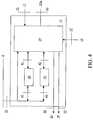
- Fig. 4illustrated with more details the construction of the logic unit 13.
- the logic unit 13comprises a logic (processing) unit 19 and a bi-directional device comprising, in the illustrated embodiment, a DTMF transmitter 20 and a modem 21 similar to the DTMF transmitter 10 and the modem 11 in the exchange 2.
- the processing unit 19that for example can be made up by electronic logic devices, processes the information on the line conditions received from the sensing arrangements 16 and 17 through the connections 33 and 37.
- the processing unit 19is connected to the DTMF transmitter 20 through connection 41 and delivers to such unit command signals in accordance with logical rules embedded or programmed in unit 19.
- the DTMF transmitter 20codifies such command signals which are sent to the exchange 2 through the connections 43 and 32 and telephone line 6.
- the processing unit 19receives information from the exchange 2 either directly through the connection 32 or through the modem 21 (connections 44 and 42) or through the DTMF transmitter 20.
- the processing unit 19is further connected to the switch 14 and the load 18 through connections 34 and 35, respectively, for delivering to such components control command signals to connect or disconnect such components.
- the userStarting from an on-hook condition, the user unhooks the telephone set and accomplishes a login (or registration) procedure to be identified or recognised by the exchange and enabled to avail of the service, i.e. to draw power from the telephone line.
- a login (or registration) procedureto be identified or recognised by the exchange and enabled to avail of the service, i.e. to draw power from the telephone line.
- the recognition and enabling proceduresimply requires the transmission of a request by the user, e.g. one or more dialled code numbers, and the exchange will automatically enable a power drawing condition from the telephone line(s).
- any line of a plurality of lines of a telephone networkcan be enabled to supply dc power to an authorised entity, such as a registered user identified by a password, pin number or other unique identifier issued by the telephone company after the signature of a contract.
- an authorised entitysuch as a registered user identified by a password, pin number or other unique identifier issued by the telephone company after the signature of a contract.
- the registered userwill be identified when calling from one line of the plurality or even from any other line of the telecommunication network, and one or more lines will be enabled to supply dc power for feeding the device(s) connected thereto.
- a callcan take place through the subscriber telephone apparatus or a dedicated apparatus, and the procedure will involve the transmission of the above identifying codes and of the telephone number(s) of the line(s) to be enabled.
- the callcould be replaced by a signalling procedure from the network device 50 in the telecommunication network 7.
- the exchange 2will properly set the logic control unit 8 to allow for the maintenance of the dc voltage on the telephone line and the delivering of an electric power although a call connection has not been established on the concerned telephone line(s).
- the line enable procedurestarts with the transmission of, for instance, a DTMF signal, issued from the subscriber apparatus 4 or from the control and feeding device 3 and delivered to the exchange 2.
- a DTMF signalissued from the subscriber apparatus 4 or from the control and feeding device 3 and delivered to the exchange 2.
- the exchange 2Upon receiving such DTMF signal, the exchange 2 disactivates the restraining process, stops the issue of the dial tone and sends a confirmation signal to the user.
- This confirmation signalis for example an audio tone or an audio signal transmitted by the modem 11 with a procedure similar to that used for sending back information to the subscriber (e.g. the CLI signal).
- a visual indicator on the control and feeding device 3, in particular in the I/O device 22A,can be actuated by such confirmation signal.
- control and feeding device 3Upon receiving the confirmation signal, the control and feeding device 3 causes the closure of the switch 14 (for example through a predetermined procedure in its logic control unit 8), and therefore the connection of the dc-dc converter 12 to the line 6, thus starting the feeding of the load 5.
- the subscriber apparatusAlthough a dc voltage is present on the subscriber line 6, the subscriber apparatus is not considered as busy by the exchange 2, and therefore an incoming call for this subscriber will be regularly forwarded. On the other hand, an outgoing call from the subscriber drawing dc power will not be prevented.
- the exchange 2forwards the ringing current along the telephone line 6 connected to the subscriber at which a power supply is being delivered.
- the logic unit 13 of the control and feeding device 3recognises this ringing current by means of the voltage and current signals from the sensor arrangement 17 and opens the switch 14 thus disconnecting the dc-dc converter 12 from the line 6 and stopping the power drawing condition.
- the ringing currentoperates the ringer of the subscriber apparatus 4 and in case the subscriber replies (i.e. lifts the handset or accomplishes an equivalent action), a normal telephone call is set up.
- the subscriberhangs on and this causes a raise of the line voltage from an operating level in the order of 7-9 V to a level in the order of 30-40 V.
- the control and feeding device 3detects this change thanks to the signal coming from the sensor arrangement 17 and causes the closure of the switch 14, thus connecting again the telephone line 6 with the dc-dc converter 12 and resuming the power drawing condition.
- the exchange 2restores the active condition previously suspended and returns to the conditions provided for the power drawing condition.
- One or more delayscan be provided for delaying the intervention of the switch 14 in order to allow the exchange to restore a condition of "USE" before the line selector is activated for properly timing the two events.
- control and feeding device 3detects the presence of a line current circulating in the telephone line due to the off-hook condition by means of the signal received from the sensor arrangement 17.
- the control and feeding device 3opens the switch 14 thus disconnecting the dc-dc converter 12 from the line 6 and stopping the power drawing condition.
- the logic unit 13sends a proper signal (e.g. a DTMF signal) to the logic control unit 8 of the exchange 2 that in response suspends the power drawing condition.
- the logic unit 13then sends a dial tone signal along the telephone line so that the exchange can accept the dialled number. From this point onwards the telephone call proceeds in a conventional manner. The return to the power drawing condition, after the end of the telephone call, is accomplished as illustrated above.
- the power deliveringcan be terminated either manually or automatically.
- the subscribercommunicates to the exchange his/her intention, for example sending one or more DTMF tones and the control and feeding device 3 is set to a suspended condition waiting for a subsequent activation.
- the exchange 2When an automatic termination is provided, e.g. when an interruption of the current in the line is detected, the exchange 2 will stop the power delivering process without any intervention from the user.
- an auxiliary load 18is provided in an embodiment of a system according to the invention.
- the logic unit 13causes the connection of the auxiliary load 18 to the switch 14 for a given time duration, typically through a delay device such as a timer.
- the current drawn by the load 18is such as to maintain a current in line 6 similar to the one drawn when feeding the device 5, whereby the termination procedure is not started.
- the auxiliary loadis removed and in case no other device 5 has been connected, the termination procedure takes place.
- An additional feature of the inventioncan be that of preventing the use of the telephone line for calls when a supply process is being carried out, or that of using two or more telephone lines at the premises of a single subscriber to increase the power drawn.
- the telecommunication network 7comprises a network device 50 which contains or is connected to a database 51.
- the database 51contains a user unique identifier for each user having subscribed to the service managed by the telephone company for feeding an electric device - different from the subscriber apparatus - through a telephone line.
- a programis installed in the logic control unit 8 for accomplishing the steps of:
- the inventioncan be used also with ISDN lines.
- the signalling procedurescould be different from those described above and be based on the typical ISDN signalling procedures.
- the whole logic and the method of the invention above describedremain the same.
- the inventionallows the use of the telephone line as a source of electric energy to feed low power electronic devices, e.g. modems and radio receivers, or to recharge batteries, e.g. those of a cellular phone.
- the power available on the telephone lineis in the order of 20 mA at 5V.
- a larger powercan be drawn for example by modifying the subscriber's apparatus connections to the switching exchange or by using twisted copper wires having larger sections.
- the inventioncan be particularly useful for emergency situations which do not affect directly the user having subscribed to a service for taking power from a telephone line.
- a servicefor taking power from a telephone line.
- a servicecan also be remotely activated by a subscriber to the service in order to allow a different user, who is actually in an emergency situation, such as for example in a black-out situation, to draw power from a telephone line available to him although the line subscriber is not a subscriber to the service.
Landscapes
- Engineering & Computer Science (AREA)
- Signal Processing (AREA)
- Telephonic Communication Services (AREA)
Description
- The present invention relates to drawing power from a telephone line to supply electrical devices, such as low power electric or electronic devices. The invention is particularly useful for supplying electric devices during an emergency situation such as a power failure of the electric network.
- As it is known, in a telephone system a conventional subscriber line connecting the switching exchange (local Central Office) to the customer's equipment comprises a pair of (twisted) copper wires carrying both the telephone signals and a dc current to power the telephone electronics.
- Most telephone companies in the world are bound to ensure continued telephone service to their customers for a given time duration in the event of a failure of the power distribution network (e.g. for 72 hours), and are equipped with backup generators so that under given circumstances a telephone line might be the only available source of (moderate) electrical power.
- Drawing a fraction of such power for feeding the subscriber apparatus is usually allowed by the telephone companies and even the feeding of additional devices at the subscriber's premises is usually tolerated when the line is in use, i.e. in telephone jargon, when the line is in an off-hook condition.
- On the other hand, the telephone companies prevent or limit the drawing of a dc power from a line in the off-hook condition for both avoiding a useless power consumption and an unauthorised feeding of other devices in the customer premises. Namely, after the subscriber has lifted the handset (or pushed a key) to be connected with the telephone exchange, a dial tone is sent to the customer apparatus and a predetermined delay is allowed for setting up the call. In case a proper selection number is not dialled and/or the call has not be set up within a given time, the line is "restrained" or set in a so called "park condition", in which the dc power supplied through the line is reduced to a very low level and a dialling is no longer allowed. Thus the user is compelled to hang up the handset, and return to an on-hook condition. The above procedure also applies in case of a misplaced handset.
- The on-hook and off-hook conditions are recognised by the central office through the current circulating in the line. Under normal (on-hook) conditions the subscriber apparatus does not draw an appreciable current (e.g. lower than 1 mA) whereas in the off-hook condition an impedance depending on the particular handset, on the line length and on other factors is connected to the line and a given range of current (loop current) is admitted.
- There have been suggested devices for drawing electrical power from a telephone line when the telephone line is in the off-hook condition.
- For example,
US 2002/0075038 A1 discloses a power supply circuit for powering an electrical device coupled to a telephone line, such as a modem using power drawn from said telephone line when this latter is in an off-hook condition. US 5,461,671 discloses a telephone line power utility circuit in which dc power supplied through a telephone line in an off-hook condition is utilised as a power source for a line terminal device.US 5,553,138 discloses a telecommunication unit requiring power even in anon-hook condition that employs a capacitor charged in the off-hook condition. When the capacitor charge becomes too low, the unit goes off-hook for a brief period of time to recharge the capacitor.DE 10041521 discloses a power supply procedure for extracting power from a subscriber's line during a commercial power supply failure in which a failure detection signal is output during failure of the power network at the subscriber's premises and electric power is then supplied from the station to the subscriber's line to operate the telephone circuit.US5937061 discloses a power saving control apparatus and method for a simple electronic exchange system which may ensure the efficient system operation and reliably maintain the operation of the system by the usage of the electric power from an auxiliary AC power in consideration of battery power even after a main AC power is down. The power saving control apparatus and method can minimally manage the operation of a corresponding telephone set when the extension subscriber is absent for a long period of time.- The power saving control apparatus for a simple electronic exchange system which is coupled to a plurality of extension telephones, each having a unit for transmitting a signal asking for setting or releasing a power saving mode and a unit for inputting passwords for each extension telephone, and operating from an auxiliary AC power when a main AC power is down, comprises: a memory for storing the passwords corresponding to the respective extension telephones; a unit for transmitting a signal requesting the input of the passwords to the extension telephones in response to a request for setting the power saving mode, which is received from an arbitrary extension telephone; a unit for checking if a password that is inputted from the extension telephone corresponds with an original password of the extension telephone previously registered in the memory; a unit for transmitting an operation limit command to the extension telephone when the two passwords coincide with each other; and a unit for cutting off a call with the extension telephone until the power saving mode is changed for another mode when the two passwords coincide with each other.
- The known devices have therefore a number of limitations and drawbacks, such as:
- The current drawing for feeding additional devices, when tolerated, is not under the control of the telephone company.
- The amount of power that can be delivered to a device is quite limited and requires the maintaining of a telephone call, i.e. an off-hook condition of the telephone line.
- There is no way to modify the power drawing limits even under circumstances that would render desirable such a power drawing.
- The current drawing interferes with the normal operation of the telephone service.
- It is therefore an object of the present invention to overcome the drawbacks and limitations of the prior art devices and methods, and particularly to allow the drawing of not negligible amounts of electrical power from a telephone line for feeding electric devices.
- It is another object of the invention to accomplish such current drawing in an on-hook condition of the telephone line and under the control of the telephone company running the utility.
- It is a further object of the invention to realise a service available to authorised subscribers for controllably drawing a dc current from a telephone line in an on-hook condition.
- The above objects of the present invention are achieved through a system, a method, a telephone exchange, a telephone network, a computer program product and a service as claimed in the hereby attached independent claims.
- Additional advantageous features are recited in the dependent claims.
- The invention allows the use of the telephone line as source of electric energy to feed low power devices (modems, radio receivers for example) or to recharge batteries (e.g. those of a cellular phone). Indicatively, on the telephone line there is available a current of 20mA at 5 V. For obtaining a larger power it is possible for instance to use more telephone lines.
- The invention provides a service of power drawing that allows control by the telephone company. Namely, according to the invention, a power drawing can be allowed either to a single authorised subscriber requesting to avail of such service, or to one or more (authorised or not) subscriber(s) following the request of a different authorised subscriber, or to (authorised or not) subscriber(s) following an enabling request from a device in the telecommunication network, e.g. an automatic enabling request following an emergency situation or a general or local power failure. Also the amount of power drawn could be increased to appreciable levels by enabling two or more lines located in the same premises and connecting them together.
- Advantageously, under emergency conditions civil defence and/or rescue personnel might need an electric power source from different locations to power or recharge cellular phones and communication devices and according to the invention such power could be easily and quickly be drawn from any telephone line to the authorised personnel.
- The invention will be now disclosed hereinbelow with reference to the attached drawings of preferred but non limiting embodiments thereof, in which:
Fig. 1 is a block diagram illustrating the arrangement for drawing electrical power from a telephone line according to the invention;Fig. 2 illustrates some components of a telephone exchange incorporating the invention;Fig. 3 illustrates an embodiment of a control and feeding device according to the invention;Fig. 4 illustrates with more details the logic unit of the control and feeding device.- Throughout all the Figures the same references have been used to indicate components that are equal or implement substantially equivalent functions.
- With reference to
Figure 1 , atelephone network 1 comprises atelephone exchange 2 connected through aconnection 22 to atelecommunication network 7 and through telephone (e.g. copper) lines to a plurality of subscribers, with only one telephone line 6 (illustrated as a physical line in the figures) and onesubscriber apparatus 4 being shown in the Figure. In accordance with the invention adevice 50 is/can be provided in thetelecommunication network 7 and connected to adatabase 51, as it will be illustrated with more details later on. - The expression "subscriber apparatus" is to be meant as indicating a generic line terminal equipment at the user's premises, such as a telephone set, a modem, a facsimile device, etc. , which is connected or connectable to the
telephone line 6 for using telecommunications services through thetelephone line 6. - In a known manner, the
telephone exchange 2 comprises an arrangement (known in the art and not shown in the Figure) for feeding a dc voltage to thesubscriber apparatus 4 through thetelephone line 6. According to the invention, at the subscriber's premises a control andfeeding device 3 is connected between the telephone exchange 2 (connection 23) and the subscriber apparatus 4 (connection 24), whereas thetelephone exchange 2 has been modified as will be illustrated in more details with reference toFig. 2 . - Through a
connection 25, the control andfeeding device 3 is connected or connectable to an additional device (or in general terms a "load") 5 to which electric power has to be delivered, such as an electric or electronic device or a battery to be recharged, which can be completely unrelated to thesubscriber apparatus 4. - The
switching exchange 2 can be a conventional exchange known in the art such as for example an AXE system from Ericsson, a UT100 system from Italtel, or other known systems. - The structure of the exchange will not be illustrated in detail but only its components that are relevant to the present description will be shown.
- With reference to
Fig. 2 , theexchange 2 comprises in particular: - a plurality of subscriber
line interface circuits 9, only one of which is shown in the Figure, adapted to handle thesubscriber lines 6 and more particularly to recognise the subscriber, to feed the telephone line in the off-hook condition and to send signals such as a dial tone to, and receiving dialling signals from, the subscriber set; - a
logic control unit 8 connecting theexchange 2 with thetelecommunication network 7 for signalling purposes; more generally saidlogic control unit 8 is associated with thetelephone exchange 2 and can also be located outside of thetelephone exchange 2; - a
bi-directional device logic control unit 8 and thesubscriber circuit 9, for recognising and applying to thelogic control unit 8 signals received by thesubscriber circuit 9 through thetelephone line 6, and for sending to saidsubscriber circuit 9 control information generated by saidlogic control unit 8 and relating to the power drawing procedure; - a
switching matrix 46 receiving a control signal from thelogic control unit 8 through aconnection 47 and a voice and data information signal from thesubscriber circuit 9 through aconnection 48, for transmitting said signal to thetelecommunication network 7. - The subscriber
line interface circuits 9 are made up by electronic circuits operating like interfaces between the subscriber lines and the control andfeeding device 3, for managing the calls and supplying power to thesubscribers lines 6. Eachsubscriber circuit 9 is provided with theconnections - The
logic control unit 8 includes application programs for handling the functionalities and the services of the exchange. - In accordance with the disclosed embodiment of the invention, the bi-directional device comprises a DTMF (Dual Tone Multi-Frequency)
transceiver 10 and amodem 11, or other devices suitable for signalling purposes such as ISDN (Integrated Service Digital Network) devices. - In a preferred embodiment which makes use of a DTMF transceiver, the
transceiver 10 is capable of decoding signals transmitted by the subscriber apparatus to theexchange 2 along thetelephone line 6. The receiver can recognise the signals generated by thesubscriber apparatus 4 and possibly by the control andfeeding device 3 through theconnection 29, and can forward them to thelogic control unit 8 through theconnection 27. - The
modem 11 can be a modem operating in the audio band used for delivering band information from the logic control unit 8 (connection 28) to the control and feeding device 3 (connection 30) and the subscriber apparatus. Such information is used to control and manage the power drawing process. - Through the
connection 22 thelogic control unit 8 exchanges the telecommunication traffic (voice and data information) with thetelecommunication network 7, whereas through theconnection 26 thelogic control unit 8 interacts with thesubscriber circuit 9. In accordance with the present invention, thelogic control unit 8 incorporates programs integrated with the existing programs to implement the functionalities required for managing the power supply service. Fig. 3 illustrates an embodiment of a control andfeeding device 3 according to the invention. This device comprises a dc-dc converter 12 connected to thetelephone line 6 through aswitch 14. The dc-dc converter 12 is adapted to convert the dc voltage present on the telephone line into a dc voltage adapted to the additional device orload 5 to be fed by the telephone line.- The connections between the
telephone line 6 and theswitch 14, and between theswitch 14 and the dc-dc converter 12 are indicated by 31 and 40, respectively. Theswitch 14 is controlled by alogic unit 13 through aconnection 34 and thelogic unit 13 is in turn connected at 32 to thetelephone line 6. - The additional
electric device 5, schematically shown inFig. 1 and also referred to as a load, is connected or connectable to the output of the dc-dc converter 12 through asensing arrangement 16 and aconnection 25. Thesensing arrangement 16 is connected to the dc-dc converter 12 through aconnection 38. The purpose of thesensing arrangement 16 is to detect the voltage applied to theload 5 and the current circulating through it and to supply this information to thelogic unit 13. Afurther sensing arrangement 17 for detecting the voltage applied to and the current circulating in the telephone line is connected to thetelephone line 6 downstream of thelogic unit 13. Typically each sensor arrangement comprises a voltage sensor and a current sensor. The information of both sensor arrangements are delivered to thelogic unit 13 throughconnections - An auxiliary device or load 18 is connected to the switch 14 (connection 36) under control of the logic unit 13 (connection 35). The
auxiliary load 18 is connected in parallel with the dc-dc converter 12 and can draw current from the telephone line when so enabled through theconnection 35 and when theswitch 14 is closed. - To the
logic unit 13 there is additionally connected through aconnection 45 an I/O device 22A for sending and receiving control and status signals. Preferably the I/O device 22A comprises an alphanumerical keyboard and a display. - The
logic unit 13 locally controls the drawing (supply) of the dc power from the telephone line and is realised by conventional electronic devices, as better detailed in the following in an exemplary embodiment. Thelogic unit 13 receives information about the state of the line 6 (on-hook or off-hook as detected by the sensor arrangement 17) and about the power drawn (voltage and current) by theload 5 through thesensor arrangement 16 andconnection 37. - The
logic unit 13 is powered by abattery 15 through aconnection 39 and is preferably rechargeable and connected so as to be recharged through the device of the invention (not shown). Fig. 4 illustrated with more details the construction of thelogic unit 13.- The
logic unit 13 comprises a logic (processing) unit 19 and a bi-directional device comprising, in the illustrated embodiment, aDTMF transmitter 20 and amodem 21 similar to theDTMF transmitter 10 and themodem 11 in theexchange 2. - The processing unit 19, that for example can be made up by electronic logic devices, processes the information on the line conditions received from the
sensing arrangements connections DTMF transmitter 20 throughconnection 41 and delivers to such unit command signals in accordance with logical rules embedded or programmed in unit 19. TheDTMF transmitter 20 codifies such command signals which are sent to theexchange 2 through theconnections telephone line 6. The processing unit 19 receives information from theexchange 2 either directly through theconnection 32 or through the modem 21 (connections 44 and 42) or through theDTMF transmitter 20. The processing unit 19 is further connected to theswitch 14 and theload 18 throughconnections - The operation of the invention will be illustrated hereinbelow.
- Starting from an on-hook condition, the user unhooks the telephone set and accomplishes a login (or registration) procedure to be identified or recognised by the exchange and enabled to avail of the service, i.e. to draw power from the telephone line. There are possible several types of recognition and enabling, each of them implying different procedures.
- In case the power drawing is allowed only to one line or to a predetermined number of telephone lines upon signature of a contract by the subscriber concerning such line(s), a so called authorised subscriber, the recognition and enabling procedure simply requires the transmission of a request by the user, e.g. one or more dialled code numbers, and the exchange will automatically enable a power drawing condition from the telephone line(s).
- In a more general situation, any line of a plurality of lines of a telephone network can be enabled to supply dc power to an authorised entity, such as a registered user identified by a password, pin number or other unique identifier issued by the telephone company after the signature of a contract.
- Under these circumstances, the registered user will be identified when calling from one line of the plurality or even from any other line of the telecommunication network, and one or more lines will be enabled to supply dc power for feeding the device(s) connected thereto. Such a call can take place through the subscriber telephone apparatus or a dedicated apparatus, and the procedure will involve the transmission of the above identifying codes and of the telephone number(s) of the line(s) to be enabled.
- In a further embodiment, the call could be replaced by a signalling procedure from the
network device 50 in thetelecommunication network 7. - To enable a line, the
exchange 2 will properly set thelogic control unit 8 to allow for the maintenance of the dc voltage on the telephone line and the delivering of an electric power although a call connection has not been established on the concerned telephone line(s). - The line enable procedure starts with the transmission of, for instance, a DTMF signal, issued from the
subscriber apparatus 4 or from the control andfeeding device 3 and delivered to theexchange 2. Upon receiving such DTMF signal, theexchange 2 disactivates the restraining process, stops the issue of the dial tone and sends a confirmation signal to the user. This confirmation signal is for example an audio tone or an audio signal transmitted by themodem 11 with a procedure similar to that used for sending back information to the subscriber (e.g. the CLI signal). A visual indicator on the control andfeeding device 3, in particular in the I/O device 22A, can be actuated by such confirmation signal. - Upon receiving the confirmation signal, the control and
feeding device 3 causes the closure of the switch 14 (for example through a predetermined procedure in its logic control unit 8), and therefore the connection of the dc-dc converter 12 to theline 6, thus starting the feeding of theload 5. - Although a dc voltage is present on the
subscriber line 6, the subscriber apparatus is not considered as busy by theexchange 2, and therefore an incoming call for this subscriber will be regularly forwarded. On the other hand, an outgoing call from the subscriber drawing dc power will not be prevented. - As for what concerns the subscriber side, in case of an incoming call, the
exchange 2 forwards the ringing current along thetelephone line 6 connected to the subscriber at which a power supply is being delivered. Thelogic unit 13 of the control andfeeding device 3 recognises this ringing current by means of the voltage and current signals from thesensor arrangement 17 and opens theswitch 14 thus disconnecting the dc-dc converter 12 from theline 6 and stopping the power drawing condition. The ringing current operates the ringer of thesubscriber apparatus 4 and in case the subscriber replies (i.e. lifts the handset or accomplishes an equivalent action), a normal telephone call is set up. - At the end of the conversation, the subscriber hangs on and this causes a raise of the line voltage from an operating level in the order of 7-9 V to a level in the order of 30-40 V. The control and
feeding device 3 detects this change thanks to the signal coming from thesensor arrangement 17 and causes the closure of theswitch 14, thus connecting again thetelephone line 6 with the dc-dc converter 12 and resuming the power drawing condition. At the end of the call theexchange 2 restores the active condition previously suspended and returns to the conditions provided for the power drawing condition. One or more delays can be provided for delaying the intervention of theswitch 14 in order to allow the exchange to restore a condition of "USE" before the line selector is activated for properly timing the two events. - In this way a telephone call can be set up and carried out without interference with the feeding process that has been temporarily stopped.
- Again at the subscriber side, in case of an outgoing call, i.e. when the subscriber connected to the
line 6 from which power is being drawn lifts the handset to initiate a call, the control andfeeding device 3 detects the presence of a line current circulating in the telephone line due to the off-hook condition by means of the signal received from thesensor arrangement 17. - As a consequence, the control and
feeding device 3 opens theswitch 14 thus disconnecting the dc-dc converter 12 from theline 6 and stopping the power drawing condition. Then thelogic unit 13 sends a proper signal (e.g. a DTMF signal) to thelogic control unit 8 of theexchange 2 that in response suspends the power drawing condition. Thelogic unit 13 then sends a dial tone signal along the telephone line so that the exchange can accept the dialled number. From this point onwards the telephone call proceeds in a conventional manner. The return to the power drawing condition, after the end of the telephone call, is accomplished as illustrated above. - Thus the normal telephone functions will not be affected by the power drawing.
- The power delivering can be terminated either manually or automatically. In case of a manual termination, the subscriber communicates to the exchange his/her intention, for example sending one or more DTMF tones and the control and
feeding device 3 is set to a suspended condition waiting for a subsequent activation. - When an automatic termination is provided, e.g. when an interruption of the current in the line is detected, the
exchange 2 will stop the power delivering process without any intervention from the user. - To meet situations of temporarily removal of the device being fed, e.g. when replacing a substantially recharged battery with another battery to be recharged, an
auxiliary load 18 is provided in an embodiment of a system according to the invention. - When the
device 5 is removed, there is a drop in the current circulating in the line that would lead to a termination of the feeding condition. To prevent this, after detecting a change of the line current through thesensor arrangement 16, thelogic unit 13 causes the connection of theauxiliary load 18 to theswitch 14 for a given time duration, typically through a delay device such as a timer. The current drawn by theload 18 is such as to maintain a current inline 6 similar to the one drawn when feeding thedevice 5, whereby the termination procedure is not started. However, after the predetermined delay has lapsed, the auxiliary load is removed and in case noother device 5 has been connected, the termination procedure takes place. - An additional feature of the invention can be that of preventing the use of the telephone line for calls when a supply process is being carried out, or that of using two or more telephone lines at the premises of a single subscriber to increase the power drawn.
- In accordance with an embodiment of the invention and by making again reference to
Figure 1 , thetelecommunication network 7 comprises anetwork device 50 which contains or is connected to adatabase 51. - The
database 51 contains a user unique identifier for each user having subscribed to the service managed by the telephone company for feeding an electric device - different from the subscriber apparatus - through a telephone line. - Preferably, a program is installed in the
logic control unit 8 for accomplishing the steps of: - managing the signalling procedure with the device at the user side for enabling the power drawing service;
- verifying whether the user is authorised to access to the service by comparing the user unique identifier, e.g. a password or a PIN number, with the data stored in the
database 51, and in positive case - activating the power drawing service at the user side, and
- disactivating the power drawing service when a manual or automatic termination of the service occurs at the user side.
- The invention can be used also with ISDN lines. In this case, the signalling procedures could be different from those described above and be based on the typical ISDN signalling procedures. However, the whole logic and the method of the invention above described remain the same.
- The invention allows the use of the telephone line as a source of electric energy to feed low power electronic devices, e.g. modems and radio receivers, or to recharge batteries, e.g. those of a cellular phone. Indicatively, the power available on the telephone line is in the order of 20 mA at 5V. A larger power can be drawn for example by modifying the subscriber's apparatus connections to the switching exchange or by using twisted copper wires having larger sections.
- The invention can be particularly useful for emergency situations which do not affect directly the user having subscribed to a service for taking power from a telephone line. In fact, such a service can also be remotely activated by a subscriber to the service in order to allow a different user, who is actually in an emergency situation, such as for example in a black-out situation, to draw power from a telephone line available to him although the line subscriber is not a subscriber to the service.
- Although the present invention has been illustrated with reference to actually preferred embodiments, it is generally subjected to other applications and modifications which fall within the scope of the invention, as it will be evident to the skilled of the art.
Claims (29)
- A system for powering an electric device (5) with power drawn from a subscriber telephone line (6) in a telephone network comprising an exchange (2) connecting a telecommunication network (7) to a subscriber apparatus (4) through said telephone line (6), said system comprising:- a control and feeding device (3) located at the subscriber's premises and connected between said telephone line (6) and the subscriber apparatus (4), and further connectable to the electric device (5) for selectively powering it;- a logic control unit (8) associated with said exchange (2) and connected between a subscriber line interface circuit (9) of the telephone line (6) and said telecommunication network (7); and- a bi-directional device (10, 11) connected between said logic control unit (8) and the subscriber line interface circuit (9) for recognising and applying to the logic control unit (8) signals received by the subscriber line interface circuit (9) through the telephone line (6), and for sending to the control and feeding device (3) through said subscriber line interface circuit (9) control information generated by said logic control unit (8) for enabling the power drawing by said electric device (5);- wherein the logic control unit (8) includes means (8, 51) for identifying a subscriber authorised to draw electrical power from said telephone line from which said drawing of electrical power is to be enabled, said identifying being performed by comparing a user identifier with the data stored in a database (51) which contains a unique identifier for each user having subscribed to a service for powering an electric device.
- A system as claimed in claim 1,characterised in that said bi-directional device comprises a DTMF transceiver (10) and a modem (11).
- A system as claimed in claim 2,characterised in that said DTMF transceiver (10) is capable of decoding signals transmitted by the subscriber apparatus (4) to the exchange (2) along said telephone line (6), of recognising signals generated by said subscriber apparatus (4) and control and feeding device (3), and of forwarding them to the logic control unit (8).
- A system as claimed in claim 2,characterised in that said modem (11) is an audio band modem adapted to deliver band information from said logic control unit (8) to said control and feeding device (3) and the subscriber apparatus (4), said band information being used to control the power drawing process.
- A system as claimed in claim 1,characterised in that said control and feeding device (3) comprises a dc-dc converter (12) connected to the telephone line (6) and connectable to said electric device (5) through a switch (14) under the control of a logic unit (13) connected to said telephone line (6).
- A system as claimed in claim 5,characterised in that said control and feeding device (3) comprises a first sensing arrangement (16) for detecting the voltage applied to said electric device (5) and the current circulating through it.
- A system as claimed in claim 6,characterised in that said logic unit (13) comprises a second sensing arrangement (17) connected to the telephone line (6) downstream of said logic unit (13) for detecting the voltage applied to and the current circulating through the telephone line.
- A system as claimed in claim 5,characterised in that said control and feeding device (3) comprises an auxiliary load (18) connectable to said switch (14) for drawing current from the telephone line (6) under control of said logic unit (13).
- A system as claimed in claim 5,characterised in that said control and feeding device (3) further comprises an I/O device (22A) for sending and receiving control and status signals.
- A system as claimed in claim 9,characterised in that said I/O device (22A) comprises an alphanumerical keyboard and a display.
- A system as claimed in claim 1,characterised in that said control and feeding device (3) is powered by a dedicated battery (15).
- A system as claimed in claim 11,characterised in that said dedicated battery (15) is rechargeable and connected to be recharged through said telephone line (6).
- A system as claimed in claims 6 and 7,characterised in that said logic unit (13) comprises a logic processing unit (19) connected to said sensing arrangements (16, 17) and a further bi-directional device connected between the logic processing unit (19) and the telephone line (6), said logic processing unit (19) being further directly connected to said telephone line (6).
- A system as claimed in claim 13,characterised in that said further bi-directional device comprises a DTMF transmitter (20) and a modem (21), said processing unit (19) being connected to said DTMF transmitter (20) to deliver to such unit command signals in accordance with predetermined logical rules, and to said modem (21) for receiving coded command signals from said exchange (2).
- A system as claimed in claim 14,characterised in that said processing unit (19) is connected to said switch (14) and said additional load (18) for delivering control command signals to connect or disconnect such components.
- A method for powering an electric device (5) through at least one telephone line in a telephone network comprising an exchange (2) connected to a plurality of subscriber apparatuses (4) through subscriber telephone lines (6), said method comprising the following steps:a) sending to a subscriber line interface circuit (9) in said exchange (2) a request for drawing electrical power from said at least one telephone line (6);b) recognising, at said exchange (2) through a bidirectional device (10, 11) connected to said subscriber line interface circuit (9), said request for drawing electrical power from said at least one telephone line (6) and identifying a subscriber authorised to draw electrical power from said at least one telephone line from which said drawing of electrical power is to be enabled, by comparing, through a logic control unit (8) associated to said exchange (2) and connected to said bidirectional device (10, 11), a user identifier with the data stored in a database (51) which contains a unique identifier for each user having subscribed to a service for powering electric devices;c) sending by said bidirectional device (10, 11), through said subscriber line interface circuit (9) and said at least one telephone line, to a control and feeding device (3) located at the subscriber's premises and connected between said telephone line (6) and said subscriber apparatus (4) and further connectable to said electric device (5), an enabling information to supply electrical power for powering said electric device (5).
- A method as claimed in claim 16,characterised in that between the steps b) and c) said method further provides the step of overriding any restriction normally provided to disconnect said at least one telephone line (6) from the exchange (2) when the line is in an off-hook condition and no call is set up, while allowing the usual operations of receiving calls from and sending calls to said subscriber apparatus, said restrictions comprising a "park" condition.
- A method as claimed in claim 16,characterised in that it further provides an adaptation of the voltage on the telephone line (6) to the characteristics of the electric device (5) to be powered.
- A method as claimed in claim 16,characterised in that said request for drawing electrical power comprises a DTMF signal.
- A method as claimed in claim 17,characterised in that upon receiving said request signal, the "park" condition is disactivated and the issue of the dial tone to the subscriber apparatus is prevented.
- A method as claimed in claim 17,characterised in further providing a step of sending a confirmation signal, such as an audio tone or signal, from the exchange to the subscriber apparatus.
- A method as claimed in claim 21,characterised in that said confirmation signal actuates a visual indicator at the subscriber's premises.
- A method for providing a service to at least one subscriber, said service comprising the powering of electric devices (5) through at least one telephone line according to the method of any of claims 16-22.
- A method for providing a service as claimed in claim 23,characterised in that between the steps b) and c) said method further provides the step of overriding any restriction normally provided to disconnect said at least one telephone line (6) from the exchange (2) when the line is in an off-hook condition and no call is set up, while allowing the usual operations of receiving calls from and sending calls to said subscriber apparatus, said restrictions comprising a "park" condition.
- A method for providing a service as claimed in claim 24,characterised in that the step of sending to said exchange (2) a request for drawing electrical power is accomplished by the subscriber to whom the service has to be supplied.
- A method for providing a service as claimed in claim 24,characterised in that the step of sending to said exchange (2) a request for drawing electrical power is accomplished by an authorised subscriber different from the subscriber(s) to whom the service has to be supplied.
- A method for providing a service as claimed in claim 24,characterised in that the step of sending to said exchange (2) a request for drawing electrical power is accomplished by a network device (50) in a telecommunication network (7) connected to said telephone exchange (2).
- Computer program embodied in a computer readable medium comprising software code portions for performing the steps of the method of any of claims 16-27.
- A telephone network comprising a system as claimed in any of claims 1-15.
Applications Claiming Priority (1)
| Application Number | Priority Date | Filing Date | Title |
|---|---|---|---|
| PCT/EP2004/003878WO2005101804A1 (en) | 2004-04-13 | 2004-04-13 | A device and a method for feeding electric devices from a telephone line |
Publications (2)
| Publication Number | Publication Date |
|---|---|
| EP1738575A1 EP1738575A1 (en) | 2007-01-03 |
| EP1738575B1true EP1738575B1 (en) | 2016-09-21 |
Family
ID=34957192
Family Applications (1)
| Application Number | Title | Priority Date | Filing Date |
|---|---|---|---|
| EP04726982.4AExpired - LifetimeEP1738575B1 (en) | 2004-04-13 | 2004-04-13 | A device and a method for feeding electric devices from a telephone line |
Country Status (3)
| Country | Link |
|---|---|
| US (1) | US8050390B2 (en) |
| EP (1) | EP1738575B1 (en) |
| WO (1) | WO2005101804A1 (en) |
Families Citing this family (1)
| Publication number | Priority date | Publication date | Assignee | Title |
|---|---|---|---|---|
| CN102404471A (en)* | 2011-11-22 | 2012-04-04 | 厦门中领科技有限公司 | Passive isolated communication device for terminal equipment of public switched telephone network |
Family Cites Families (18)
| Publication number | Priority date | Publication date | Assignee | Title |
|---|---|---|---|---|
| US4295008A (en)* | 1979-03-23 | 1981-10-13 | Small World Exchange, Inc. | Telephone-conferencing apparatus and method having response tallying |
| JPH01248835A (en)* | 1988-03-30 | 1989-10-04 | Nec Corp | Receiver charger for radio calling |
| JPH0264261U (en)* | 1988-11-04 | 1990-05-15 | ||
| US4961220A (en)* | 1988-12-21 | 1990-10-02 | Spectrum Concepts, Inc. | Power management in a microprocessor-controlled battery-powered telephone device |
| US5222125A (en)* | 1991-09-03 | 1993-06-22 | At&T Bell Laboratories | System for providing personalized telephone calling features |
| CA2097449C (en)* | 1992-06-05 | 1998-09-15 | Satosi Sakuragi | Telephone line power utility circuit |
| US5343514A (en)* | 1993-12-10 | 1994-08-30 | Snyder Gary K | Telephone line powered system |
| US5608792A (en)* | 1994-04-13 | 1997-03-04 | British Telecommunications Public Limited Company | Apparatus for drawing and processing electrical power from a communications line |
| US5553138A (en)* | 1994-05-13 | 1996-09-03 | Compaq Computer Corporation | Telephone line sourced power supply |
| KR0169421B1 (en)* | 1995-12-30 | 1999-02-01 | 김광호 | Control method of power saving in temporary switching system |
| JP3793298B2 (en)* | 1996-11-29 | 2006-07-05 | ユニデン株式会社 | Telephone equipment |
| US6212226B1 (en)* | 1997-08-08 | 2001-04-03 | Lucent Technologies, Inc. | Supplemental power for battery operated modems |
| US6256518B1 (en)* | 1997-10-10 | 2001-07-03 | At&T Corp. | System for providing power to a wireless system |
| AT409909B (en)* | 1998-12-22 | 2002-12-27 | Ericsson Austria Ag | Circuit for remote supply in communications system enables local station to control source in exchange via transmission line depending on load requirement |
| US7095848B1 (en)* | 1999-08-03 | 2006-08-22 | Agere Systems Inc. | Power up reset circuit for line powered circuit |
| JP3747702B2 (en)* | 1999-08-24 | 2006-02-22 | 日本電気株式会社 | DSL power supply method, DSL power supply system, subscriber-side network terminator, and station-side line terminator |
| US20020075038A1 (en)* | 2000-12-19 | 2002-06-20 | Intel Corporation | Active leakage control technique for high performance dynamic circuits |
| US7454012B2 (en)* | 2002-04-29 | 2008-11-18 | Adc Dsl Systems, Inc. | Managing power in a line powered network element |
- 2004
- 2004-04-13WOPCT/EP2004/003878patent/WO2005101804A1/ennot_activeApplication Discontinuation
- 2004-04-13EPEP04726982.4Apatent/EP1738575B1/ennot_activeExpired - Lifetime
- 2004-04-13USUS11/578,038patent/US8050390B2/ennot_activeExpired - Fee Related
Also Published As
| Publication number | Publication date |
|---|---|
| WO2005101804A1 (en) | 2005-10-27 |
| US20070258580A1 (en) | 2007-11-08 |
| EP1738575A1 (en) | 2007-01-03 |
| US8050390B2 (en) | 2011-11-01 |
Similar Documents
| Publication | Publication Date | Title |
|---|---|---|
| US5390233A (en) | Telephone call transfer between a wireless and wired telephone | |
| US6466799B1 (en) | Premises telephonic interface system for communicating using a hand-held wireless device | |
| EP0474407A1 (en) | Telemetry access arrangement | |
| EP0424495B1 (en) | Voice messaging for pay phone telephone systems | |
| EP0684722B1 (en) | Diverter interface between two telecommunication lines and a subscriber station set | |
| CN102104667A (en) | Mobile phone and on-hook method thereof | |
| US5553122A (en) | Universal wedge-type telephone adaptor for computer system | |
| EP1738575B1 (en) | A device and a method for feeding electric devices from a telephone line | |
| US7761086B2 (en) | Communication terminal, service providing equipment, common setup information management equipment, and communication control method | |
| US6658101B1 (en) | Interface device for communication between an external network subscriber's terminal installation and an internal network | |
| KR960014229B1 (en) | How to register and cancel the out-of-office guidance function of the exchange system | |
| JP3091065B2 (en) | Communication device for data transmission by no ringing | |
| EP0331531A2 (en) | Telephone apparatus and a method of controlling same | |
| US7359500B2 (en) | Method for carrying out predetermined actions by a receiving telecom device using an answer prefix | |
| JP4128072B2 (en) | Automatic remote meter reading system and terminal network control device | |
| US5999615A (en) | Telephone exchange system and switching connection method improved in efficiency for long-distance calling | |
| KR100327404B1 (en) | Method for service to connect communication upon disconnection of communication from mobile station | |
| JP3451794B2 (en) | Terminal adapter with hot line function | |
| CN1642196B (en) | A method of receiving information entered by a telephone user | |
| JP2856261B2 (en) | Adapter device for analog terminal connection | |
| JP2944150B2 (en) | Private branch exchange billing control method | |
| KR0133069B1 (en) | Telecommunication system with non-visioned terminal by telephone switching network using two consecutive calls | |
| JPH0723106A (en) | Toll telephone communication system | |
| JPH10136190A (en) | Facsimile communication management device | |
| JPH05236108A (en) | Exchange system |
Legal Events
| Date | Code | Title | Description |
|---|---|---|---|
| PUAI | Public reference made under article 153(3) epc to a published international application that has entered the european phase | Free format text:ORIGINAL CODE: 0009012 | |
| 17P | Request for examination filed | Effective date:20061005 | |
| AK | Designated contracting states | Kind code of ref document:A1 Designated state(s):AT BE BG CH CY CZ DE DK EE ES FI FR GB GR HU IE IT LI LU MC NL PL PT RO SE SI SK TR | |
| 17Q | First examination report despatched | Effective date:20070605 | |
| DAX | Request for extension of the european patent (deleted) | ||
| RAP1 | Party data changed (applicant data changed or rights of an application transferred) | Owner name:TELECOM ITALIA S.P.A. Owner name:PIRELLI & C. S.P.A. | |
| RAP1 | Party data changed (applicant data changed or rights of an application transferred) | Owner name:PIRELLI & C. S.P.A. Owner name:TELECOM ITALIA S.P.A. | |
| GRAP | Despatch of communication of intention to grant a patent | Free format text:ORIGINAL CODE: EPIDOSNIGR1 | |
| INTG | Intention to grant announced | Effective date:20160512 | |
| GRAS | Grant fee paid | Free format text:ORIGINAL CODE: EPIDOSNIGR3 | |
| GRAA | (expected) grant | Free format text:ORIGINAL CODE: 0009210 | |
| AK | Designated contracting states | Kind code of ref document:B1 Designated state(s):AT BE BG CH CY CZ DE DK EE ES FI FR GB GR HU IE IT LI LU MC NL PL PT RO SE SI SK TR | |
| REG | Reference to a national code | Ref country code:GB Ref legal event code:FG4D | |
| REG | Reference to a national code | Ref country code:CH Ref legal event code:EP | |
| REG | Reference to a national code | Ref country code:AT Ref legal event code:REF Ref document number:831859 Country of ref document:AT Kind code of ref document:T Effective date:20161015 | |
| REG | Reference to a national code | Ref country code:IE Ref legal event code:FG4D | |
| REG | Reference to a national code | Ref country code:DE Ref legal event code:R096 Ref document number:602004049976 Country of ref document:DE | |
| REG | Reference to a national code | Ref country code:NL Ref legal event code:MP Effective date:20160921 | |
| PG25 | Lapsed in a contracting state [announced via postgrant information from national office to epo] | Ref country code:FI Free format text:LAPSE BECAUSE OF FAILURE TO SUBMIT A TRANSLATION OF THE DESCRIPTION OR TO PAY THE FEE WITHIN THE PRESCRIBED TIME-LIMIT Effective date:20160921 | |
| REG | Reference to a national code | Ref country code:AT Ref legal event code:MK05 Ref document number:831859 Country of ref document:AT Kind code of ref document:T Effective date:20160921 | |
| PG25 | Lapsed in a contracting state [announced via postgrant information from national office to epo] | Ref country code:NL Free format text:LAPSE BECAUSE OF FAILURE TO SUBMIT A TRANSLATION OF THE DESCRIPTION OR TO PAY THE FEE WITHIN THE PRESCRIBED TIME-LIMIT Effective date:20160921 Ref country code:SE Free format text:LAPSE BECAUSE OF FAILURE TO SUBMIT A TRANSLATION OF THE DESCRIPTION OR TO PAY THE FEE WITHIN THE PRESCRIBED TIME-LIMIT Effective date:20160921 Ref country code:GR Free format text:LAPSE BECAUSE OF FAILURE TO SUBMIT A TRANSLATION OF THE DESCRIPTION OR TO PAY THE FEE WITHIN THE PRESCRIBED TIME-LIMIT Effective date:20161222 | |
| REG | Reference to a national code | Ref country code:FR Ref legal event code:PLFP Year of fee payment:14 | |
| PG25 | Lapsed in a contracting state [announced via postgrant information from national office to epo] | Ref country code:RO Free format text:LAPSE BECAUSE OF FAILURE TO SUBMIT A TRANSLATION OF THE DESCRIPTION OR TO PAY THE FEE WITHIN THE PRESCRIBED TIME-LIMIT Effective date:20160921 Ref country code:EE Free format text:LAPSE BECAUSE OF FAILURE TO SUBMIT A TRANSLATION OF THE DESCRIPTION OR TO PAY THE FEE WITHIN THE PRESCRIBED TIME-LIMIT Effective date:20160921 | |
| PG25 | Lapsed in a contracting state [announced via postgrant information from national office to epo] | Ref country code:CZ Free format text:LAPSE BECAUSE OF FAILURE TO SUBMIT A TRANSLATION OF THE DESCRIPTION OR TO PAY THE FEE WITHIN THE PRESCRIBED TIME-LIMIT Effective date:20160921 Ref country code:AT Free format text:LAPSE BECAUSE OF FAILURE TO SUBMIT A TRANSLATION OF THE DESCRIPTION OR TO PAY THE FEE WITHIN THE PRESCRIBED TIME-LIMIT Effective date:20160921 Ref country code:BG Free format text:LAPSE BECAUSE OF FAILURE TO SUBMIT A TRANSLATION OF THE DESCRIPTION OR TO PAY THE FEE WITHIN THE PRESCRIBED TIME-LIMIT Effective date:20161221 Ref country code:ES Free format text:LAPSE BECAUSE OF FAILURE TO SUBMIT A TRANSLATION OF THE DESCRIPTION OR TO PAY THE FEE WITHIN THE PRESCRIBED TIME-LIMIT Effective date:20160921 Ref country code:SK Free format text:LAPSE BECAUSE OF FAILURE TO SUBMIT A TRANSLATION OF THE DESCRIPTION OR TO PAY THE FEE WITHIN THE PRESCRIBED TIME-LIMIT Effective date:20160921 Ref country code:BE Free format text:LAPSE BECAUSE OF FAILURE TO SUBMIT A TRANSLATION OF THE DESCRIPTION OR TO PAY THE FEE WITHIN THE PRESCRIBED TIME-LIMIT Effective date:20160921 Ref country code:PT Free format text:LAPSE BECAUSE OF FAILURE TO SUBMIT A TRANSLATION OF THE DESCRIPTION OR TO PAY THE FEE WITHIN THE PRESCRIBED TIME-LIMIT Effective date:20170123 Ref country code:PL Free format text:LAPSE BECAUSE OF FAILURE TO SUBMIT A TRANSLATION OF THE DESCRIPTION OR TO PAY THE FEE WITHIN THE PRESCRIBED TIME-LIMIT Effective date:20160921 | |
| REG | Reference to a national code | Ref country code:DE Ref legal event code:R097 Ref document number:602004049976 Country of ref document:DE | |
| PLBE | No opposition filed within time limit | Free format text:ORIGINAL CODE: 0009261 | |
| STAA | Information on the status of an ep patent application or granted ep patent | Free format text:STATUS: NO OPPOSITION FILED WITHIN TIME LIMIT | |
| PG25 | Lapsed in a contracting state [announced via postgrant information from national office to epo] | Ref country code:DK Free format text:LAPSE BECAUSE OF FAILURE TO SUBMIT A TRANSLATION OF THE DESCRIPTION OR TO PAY THE FEE WITHIN THE PRESCRIBED TIME-LIMIT Effective date:20160921 | |
| 26N | No opposition filed | Effective date:20170622 | |
| PG25 | Lapsed in a contracting state [announced via postgrant information from national office to epo] | Ref country code:SI Free format text:LAPSE BECAUSE OF FAILURE TO SUBMIT A TRANSLATION OF THE DESCRIPTION OR TO PAY THE FEE WITHIN THE PRESCRIBED TIME-LIMIT Effective date:20160921 | |
| REG | Reference to a national code | Ref country code:CH Ref legal event code:PL | |
| REG | Reference to a national code | Ref country code:IE Ref legal event code:MM4A | |
| PG25 | Lapsed in a contracting state [announced via postgrant information from national office to epo] | Ref country code:MC Free format text:LAPSE BECAUSE OF FAILURE TO SUBMIT A TRANSLATION OF THE DESCRIPTION OR TO PAY THE FEE WITHIN THE PRESCRIBED TIME-LIMIT Effective date:20160921 | |
| PG25 | Lapsed in a contracting state [announced via postgrant information from national office to epo] | Ref country code:LU Free format text:LAPSE BECAUSE OF NON-PAYMENT OF DUE FEES Effective date:20170413 Ref country code:CH Free format text:LAPSE BECAUSE OF NON-PAYMENT OF DUE FEES Effective date:20170430 Ref country code:LI Free format text:LAPSE BECAUSE OF NON-PAYMENT OF DUE FEES Effective date:20170430 | |
| REG | Reference to a national code | Ref country code:FR Ref legal event code:PLFP Year of fee payment:15 | |
| PG25 | Lapsed in a contracting state [announced via postgrant information from national office to epo] | Ref country code:IE Free format text:LAPSE BECAUSE OF NON-PAYMENT OF DUE FEES Effective date:20170413 | |
| PGFP | Annual fee paid to national office [announced via postgrant information from national office to epo] | Ref country code:DE Payment date:20180427 Year of fee payment:15 | |
| PGFP | Annual fee paid to national office [announced via postgrant information from national office to epo] | Ref country code:IT Payment date:20180423 Year of fee payment:15 Ref country code:FR Payment date:20180425 Year of fee payment:15 | |
| PGFP | Annual fee paid to national office [announced via postgrant information from national office to epo] | Ref country code:GB Payment date:20180427 Year of fee payment:15 | |
| PG25 | Lapsed in a contracting state [announced via postgrant information from national office to epo] | Ref country code:HU Free format text:LAPSE BECAUSE OF FAILURE TO SUBMIT A TRANSLATION OF THE DESCRIPTION OR TO PAY THE FEE WITHIN THE PRESCRIBED TIME-LIMIT; INVALID AB INITIO Effective date:20040413 | |
| PG25 | Lapsed in a contracting state [announced via postgrant information from national office to epo] | Ref country code:CY Free format text:LAPSE BECAUSE OF NON-PAYMENT OF DUE FEES Effective date:20160921 | |
| REG | Reference to a national code | Ref country code:DE Ref legal event code:R119 Ref document number:602004049976 Country of ref document:DE | |
| GBPC | Gb: european patent ceased through non-payment of renewal fee | Effective date:20190413 | |
| PG25 | Lapsed in a contracting state [announced via postgrant information from national office to epo] | Ref country code:GB Free format text:LAPSE BECAUSE OF NON-PAYMENT OF DUE FEES Effective date:20190413 Ref country code:DE Free format text:LAPSE BECAUSE OF NON-PAYMENT OF DUE FEES Effective date:20191101 | |
| PG25 | Lapsed in a contracting state [announced via postgrant information from national office to epo] | Ref country code:FR Free format text:LAPSE BECAUSE OF NON-PAYMENT OF DUE FEES Effective date:20190430 | |
| PG25 | Lapsed in a contracting state [announced via postgrant information from national office to epo] | Ref country code:TR Free format text:LAPSE BECAUSE OF FAILURE TO SUBMIT A TRANSLATION OF THE DESCRIPTION OR TO PAY THE FEE WITHIN THE PRESCRIBED TIME-LIMIT Effective date:20160921 | |
| PG25 | Lapsed in a contracting state [announced via postgrant information from national office to epo] | Ref country code:IT Free format text:LAPSE BECAUSE OF NON-PAYMENT OF DUE FEES Effective date:20190413 |