EP1737076B1 - Receptacle electrical connector - Google Patents
Receptacle electrical connectorDownload PDFInfo
- Publication number
- EP1737076B1 EP1737076B1EP06018785AEP06018785AEP1737076B1EP 1737076 B1EP1737076 B1EP 1737076B1EP 06018785 AEP06018785 AEP 06018785AEP 06018785 AEP06018785 AEP 06018785AEP 1737076 B1EP1737076 B1EP 1737076B1
- Authority
- EP
- European Patent Office
- Prior art keywords
- connector
- contact
- plug
- housing
- contacts
- Prior art date
- Legal status (The legal status is an assumption and is not a legal conclusion. Google has not performed a legal analysis and makes no representation as to the accuracy of the status listed.)
- Expired - Lifetime
Links
- 230000013011matingEffects0.000claimsabstractdescription24
- 230000000694effectsEffects0.000claimsdescription3
- 230000010287polarizationEffects0.000claimsdescription3
- 230000001681protective effectEffects0.000claimsdescription2
- 230000000295complement effectEffects0.000claims1
- 239000004020conductorSubstances0.000claims1
- 239000000463materialSubstances0.000description13
- 230000000717retained effectEffects0.000description11
- 230000017525heat dissipationEffects0.000description10
- 230000014759maintenance of locationEffects0.000description10
- 238000003780insertionMethods0.000description8
- 230000037431insertionEffects0.000description8
- 238000013461designMethods0.000description7
- 238000005192partitionMethods0.000description5
- 238000010348incorporationMethods0.000description4
- 230000007246mechanismEffects0.000description4
- 229910000906BronzeInorganic materials0.000description3
- 229910000881Cu alloyInorganic materials0.000description3
- OAICVXFJPJFONN-UHFFFAOYSA-NPhosphorusChemical compound[P]OAICVXFJPJFONN-UHFFFAOYSA-N0.000description3
- 230000008901benefitEffects0.000description3
- DMFGNRRURHSENX-UHFFFAOYSA-Nberyllium copperChemical compound[Be].[Cu]DMFGNRRURHSENX-UHFFFAOYSA-N0.000description3
- 238000010276constructionMethods0.000description3
- 239000004033plasticSubstances0.000description3
- 230000008859changeEffects0.000description2
- 230000007797corrosionEffects0.000description2
- 238000005260corrosionMethods0.000description2
- 230000009977dual effectEffects0.000description2
- 230000002708enhancing effectEffects0.000description2
- 229910052751metalInorganic materials0.000description2
- 239000002184metalSubstances0.000description2
- 238000012986modificationMethods0.000description2
- 230000004048modificationEffects0.000description2
- 238000000926separation methodMethods0.000description2
- 241001067915Sagittaria kurzianaSpecies0.000description1
- 238000007792additionMethods0.000description1
- 230000002411adverseEffects0.000description1
- 230000009286beneficial effectEffects0.000description1
- 230000008878couplingEffects0.000description1
- 238000010168coupling processMethods0.000description1
- 238000005859coupling reactionMethods0.000description1
- 238000011161developmentMethods0.000description1
- 230000018109developmental processEffects0.000description1
- 230000020169heat generationEffects0.000description1
- 239000002991molded plasticSubstances0.000description1
- 239000000758substrateSubstances0.000description1
Images


Classifications
- H—ELECTRICITY
- H01—ELECTRIC ELEMENTS
- H01R—ELECTRICALLY-CONDUCTIVE CONNECTIONS; STRUCTURAL ASSOCIATIONS OF A PLURALITY OF MUTUALLY-INSULATED ELECTRICAL CONNECTING ELEMENTS; COUPLING DEVICES; CURRENT COLLECTORS
- H01R11/00—Individual connecting elements providing two or more spaced connecting locations for conductive members which are, or may be, thereby interconnected, e.g. end pieces for wires or cables supported by the wire or cable and having means for facilitating electrical connection to some other wire, terminal, or conductive member, blocks of binding posts
- H01R11/11—End pieces or tapping pieces for wires, supported by the wire and for facilitating electrical connection to some other wire, terminal or conductive member
- H01R11/22—End pieces terminating in a spring clip
- H—ELECTRICITY
- H01—ELECTRIC ELEMENTS
- H01R—ELECTRICALLY-CONDUCTIVE CONNECTIONS; STRUCTURAL ASSOCIATIONS OF A PLURALITY OF MUTUALLY-INSULATED ELECTRICAL CONNECTING ELEMENTS; COUPLING DEVICES; CURRENT COLLECTORS
- H01R13/00—Details of coupling devices of the kinds covered by groups H01R12/70 or H01R24/00 - H01R33/00
- H01R13/02—Contact members
- H01R13/10—Sockets for co-operation with pins or blades
- H—ELECTRICITY
- H01—ELECTRIC ELEMENTS
- H01R—ELECTRICALLY-CONDUCTIVE CONNECTIONS; STRUCTURAL ASSOCIATIONS OF A PLURALITY OF MUTUALLY-INSULATED ELECTRICAL CONNECTING ELEMENTS; COUPLING DEVICES; CURRENT COLLECTORS
- H01R12/00—Structural associations of a plurality of mutually-insulated electrical connecting elements, specially adapted for printed circuits, e.g. printed circuit boards [PCB], flat or ribbon cables, or like generally planar structures, e.g. terminal strips, terminal blocks; Coupling devices specially adapted for printed circuits, flat or ribbon cables, or like generally planar structures; Terminals specially adapted for contact with, or insertion into, printed circuits, flat or ribbon cables, or like generally planar structures
- H01R12/70—Coupling devices
- H01R12/7088—Arrangements for power supply
- H—ELECTRICITY
- H01—ELECTRIC ELEMENTS
- H01R—ELECTRICALLY-CONDUCTIVE CONNECTIONS; STRUCTURAL ASSOCIATIONS OF A PLURALITY OF MUTUALLY-INSULATED ELECTRICAL CONNECTING ELEMENTS; COUPLING DEVICES; CURRENT COLLECTORS
- H01R12/00—Structural associations of a plurality of mutually-insulated electrical connecting elements, specially adapted for printed circuits, e.g. printed circuit boards [PCB], flat or ribbon cables, or like generally planar structures, e.g. terminal strips, terminal blocks; Coupling devices specially adapted for printed circuits, flat or ribbon cables, or like generally planar structures; Terminals specially adapted for contact with, or insertion into, printed circuits, flat or ribbon cables, or like generally planar structures
- H01R12/70—Coupling devices
- H01R12/71—Coupling devices for rigid printing circuits or like structures
- H01R12/72—Coupling devices for rigid printing circuits or like structures coupling with the edge of the rigid printed circuits or like structures
- H01R12/722—Coupling devices for rigid printing circuits or like structures coupling with the edge of the rigid printed circuits or like structures coupling devices mounted on the edge of the printed circuits
- H01R12/727—Coupling devices presenting arrays of contacts
- H—ELECTRICITY
- H01—ELECTRIC ELEMENTS
- H01R—ELECTRICALLY-CONDUCTIVE CONNECTIONS; STRUCTURAL ASSOCIATIONS OF A PLURALITY OF MUTUALLY-INSULATED ELECTRICAL CONNECTING ELEMENTS; COUPLING DEVICES; CURRENT COLLECTORS
- H01R13/00—Details of coupling devices of the kinds covered by groups H01R12/70 or H01R24/00 - H01R33/00
- H01R13/02—Contact members
- H01R13/04—Pins or blades for co-operation with sockets
- H01R13/05—Resilient pins or blades
- H01R13/055—Resilient pins or blades co-operating with sockets having a rectangular transverse section
- H—ELECTRICITY
- H01—ELECTRIC ELEMENTS
- H01R—ELECTRICALLY-CONDUCTIVE CONNECTIONS; STRUCTURAL ASSOCIATIONS OF A PLURALITY OF MUTUALLY-INSULATED ELECTRICAL CONNECTING ELEMENTS; COUPLING DEVICES; CURRENT COLLECTORS
- H01R12/00—Structural associations of a plurality of mutually-insulated electrical connecting elements, specially adapted for printed circuits, e.g. printed circuit boards [PCB], flat or ribbon cables, or like generally planar structures, e.g. terminal strips, terminal blocks; Coupling devices specially adapted for printed circuits, flat or ribbon cables, or like generally planar structures; Terminals specially adapted for contact with, or insertion into, printed circuits, flat or ribbon cables, or like generally planar structures
- H01R12/70—Coupling devices
- H01R12/71—Coupling devices for rigid printing circuits or like structures
- H01R12/72—Coupling devices for rigid printing circuits or like structures coupling with the edge of the rigid printed circuits or like structures
- H01R12/722—Coupling devices for rigid printing circuits or like structures coupling with the edge of the rigid printed circuits or like structures coupling devices mounted on the edge of the printed circuits
- H01R12/724—Coupling devices for rigid printing circuits or like structures coupling with the edge of the rigid printed circuits or like structures coupling devices mounted on the edge of the printed circuits containing contact members forming a right angle
- Y—GENERAL TAGGING OF NEW TECHNOLOGICAL DEVELOPMENTS; GENERAL TAGGING OF CROSS-SECTIONAL TECHNOLOGIES SPANNING OVER SEVERAL SECTIONS OF THE IPC; TECHNICAL SUBJECTS COVERED BY FORMER USPC CROSS-REFERENCE ART COLLECTIONS [XRACs] AND DIGESTS
- Y10—TECHNICAL SUBJECTS COVERED BY FORMER USPC
- Y10S—TECHNICAL SUBJECTS COVERED BY FORMER USPC CROSS-REFERENCE ART COLLECTIONS [XRACs] AND DIGESTS
- Y10S439/00—Electrical connectors
- Y10S439/947—PCB mounted connector with ground terminal
- Y—GENERAL TAGGING OF NEW TECHNOLOGICAL DEVELOPMENTS; GENERAL TAGGING OF CROSS-SECTIONAL TECHNOLOGIES SPANNING OVER SEVERAL SECTIONS OF THE IPC; TECHNICAL SUBJECTS COVERED BY FORMER USPC CROSS-REFERENCE ART COLLECTIONS [XRACs] AND DIGESTS
- Y10—TECHNICAL SUBJECTS COVERED BY FORMER USPC
- Y10S—TECHNICAL SUBJECTS COVERED BY FORMER USPC CROSS-REFERENCE ART COLLECTIONS [XRACs] AND DIGESTS
- Y10S439/00—Electrical connectors
- Y10S439/949—Junction box with busbar for plug-socket type interconnection with receptacle
Definitions
- the present inventionrelates to electrical connectors and more particularly to electronic power connectors especially, useful in circuit board or backplane interconnection systems.
- Conventional plug contacts in circuit board electrical power connectorsare generally of rectangular (blade-like) or circular (pin-like) cross-section. These are so-called “singular-mass” designs.
- the opposing receptacle contactscomprise a pair of inwardly urged cantilever beams and the mating blade or pin is located between the pair of beams.
- Such arrangementsare difficult to reduce in size without adversely effecting heat dissipation capabilities. They also provide only minimal flexibility to change contact normal forces by adjustment of contact geometry.
- DE 34 41 416describes an electrical plug connector which consists essentially of a male strip and of a female strip, the latter of which is provided with a large number of essentially identical chambers in which contact elements are accommodated and held which have spring parts, which form a plug region, and connecting parts, which form a connecting region.
- DE 40 01 104describes a connector which comprises plugs and sockets, at least one of which has a conductive connector, which has an isolating housing which can be snap fitted together by snap fittings.
- the part with the connectoris formed of a number of elements corresponding to a number of poles and each having a contact and a connector and a frame with a receiving chamber for each element.
- DE 23 50 834describes an electrical power coupling with at least one plug contact disposed in a chamber of an insulating body, the plug contact being made of spring tape material and having one end configured as a flat plug tongue and the other end configured as a fork contact spring for electrically conductive receiving a flat plug.
- the present inventionrelates to an electrical connector according to claim 1.
- An electrical power connectoris described herein that incorporates contacts for establishing AC power cable connections into a single housing along with the power connector contacts that are otherwise described herein. Incorporation of AC power cable connections directly into the insulative housing that forms the internal power connector eliminates the need for any transitional type, stand-alone AC power supply connection system such as that described above.
- the connector housing incorporating the AC power connection capabilitycan accommodate different forms of AC power supply termination contacts, such as spade-type contacts for receiving discrete fast-on terminals or contacts described herein for connection to bus bars.
- a plug contact 10 for use in a plug connectoris shown.
- This plug contacthas two opposed major side walls 12 and 14.
- a front projection, identified generally by numeral 16has an upper section 18 and a lower section 20.
- Each of these upper and lower sectionscomprises a pair of opposed cantilever beams, each beam having inwardly converging proximal section 22, arcuate contact section 24 and a distal section 26.
- the opposed distal sections 26are preferably parallel to each other.
- the distal sectionscan be positioned slightly apart when the beams are in relaxed condition, but come together when the beams are deflected as the front projection is inserted into a receptacle contact (as explained below). This provides over-stress protection for the beams during mating.
- the side wallsalso include planar panels 28 and 30.
- Terminals 32, 34, 36 and 38extend from an edge of panel 28.
- Terminal 40extends from panel 30, along with a plurality of like terminals (not shown).
- Terminals 32-40can comprise through hole, solder-to-board pins (as shown), press fit pins or surface mount tails.
- the panels 28 and 30are connected by upper arcuate bridging elements 42 and 44.
- a medial space 46, adapted for airflow,is defined between the panels 28 and 30.
- the contact 10is stamped or otherwise formed as a single piece from a strip of suitable contact materials such as phosphor bronze alloys or beryllium copper alloys.
- receptacle contact 48is shown.
- This receptacle contacthas opposed, preferably planar and parallel side walls 50 and 52. These walls extend forwardly in a front projecting portion 54, that forms a medial plug receiving space 56.
- the distance between walls 50 and 52 at portion 54is such that the projection 16 of the plug contact 10 is receivable in the plug contact receiving space 56, with the beams being resiliently deflected toward the center plane of contact 10. The deflection causes the beams to develop outwardly directed forces, thereby pressing the arcuate portions 24 against the inside surfaces of the portions 54 forming the receiving space 56, to develop suitable contact normal force.
- the side walls 50 and 52also include, respectively, panels 58 and 60.
- terminals 62, 64, 66 and 68Extending from panel 60 there are terminals 62, 64, 66 and 68. Extending from panel 60 there is terminal 70 as well as several other terminals (not shown). These terminals are essentially the same as previously described terminals 32-40.
- the side walls 50 and 52are joined together by generally arcuate bridging elements 72 and 74.
- the receptacle contactis also stamped or otherwise formed in a single piece from a strip of phosphor bronze alloy or beryllium copper alloy.
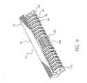
- Figs. 5-9illustrate a plug connector 75 having an insulative plug housing 76.
- the housing 76includes a front side 78 having a plurality of power contact apertures 84 and 86.
- the front projection or mating portion 16 ( Figs. 1and 2 ) of the plug contactsis disposed in apertures 84, 86.
- the plug contacts 10are retained in the housing 76 by an interference fit between the contact and the housing. This is accomplished by having the dimension H ( Fig. 2 ), the dimension between bottom edge of wall 12 and the top of bridging element 42, slightly greater than the dimension of the cavity in housing 76 that receives this portion of plug contact 10.
- the front side 78may also include a signal pin array opening 88 for housing a signal pin array designated generally as numeral 90.
- the housing 76also includes a number of rear vertical partitions, such as partitions 92 and 94, which form power contact retaining slots 96 for housing the plug contacts 98.
- the opposed medial vertical partitions 100 and 102form between them a rear signal pin array space 104 for housing the rear portion 106 of the signal pins.
- the housing 76also includes opposed rear mounting brackets 108 and 110 which have respectively mounting apertures 112 and 114.
- the plug contacts 10have terminals 32, 34, 36, 38 and 40 extending below a bottom edge 80 of housing 76.
- the edge 80forms a mounting interface, along which the housing is mounted to a printed circuit board or other structure on which the connector is mounted.
- Receptacle 128has an insulative housing 129 with a front side 130 including a plurality of silos 131 having contact openings, such as openings 136 and 138.
- the front side 130forms a mating interface of the connector 128 for mating with plug connector 75.
- the silos 131are configured and sized to be received in openings 84, 86 of connector 75.
- the front portions 54 ( Figs. 3-4 ) of the receptacle contactsare disposed within silos 131 and openings 136, 138 are sized and configured to receive the upper and lower sections 18 and 20 of plug contacts 10.
- the front side 130has a signal pin receiving area 140 with signal pin receiving apertures.
- the housing 129also has a plurality of rear partitions, such as partitions 144 and 146, which form contact retaining slots 148 for housing receptacle contacts 48.
- Signal pin housing 152receives a signal receptacle contact array 154.
- the housing 129also includes opposed rear mounting brackets 156 and 158 which have, respectively, mounting apertures 160 and 162.
- the receptacle contact terminals 62, 64, 66, 68 and 70extend beneath surface 137, that forms the mounting interface of receptacle connector 128..
- the front side 130 of the housing 128also has a plurality of vertical spaces 176 and 178, disposed between silos 131.
- the receptacle contacts 48are retained in housing 129 by an interference fit in essentially the same manner as previously described with respect to plug contacts 10. Retaining the contacts in this fashion allows substantial portions of the walls 12, 14 of the plug contact and walls 58, 60 of the receptacle contact to be spaced from surrounding parts of the respective housings 76 and 129. This leaves a substantial proportion of the surface area of both contacts (including the plug contacts), exposed to air, thereby enhancing heat dissipation capabilities, principally through convection. Such enhanced heat dissipation capabilities are desirable for power contacts.
- Fig. 15shows another plug connector 200 embodying the invention.
- the housing 202preferably formed of a molded polymeric material, has a front face 204 that forms the mating interface of the connector.
- the face 204includes a plurality of openings, such as openings 206, formed in a linear array.
- the plug connector 200includes a plurality of plug contacts 208.
- the contacts 208are inserted from the rear of the housing into cavities 212 that extend from the rear of the housing toward the front of the housing.
- the contact portions 210 with contacts 208are disposed in the openings 206.
- the plug contact 208is similar in many respects to the plug contacts shown in Fig. 1 . It includes spaced panel-like walls 214, 216 that preferably are planar and substantially parallel. The walls 214, 216 are joined by a front bridging element 218 and a rear bridging element 220.
- the contact section 210is formed by two opposed cantilevered beams 211 that extend from front edges of the walls 214, 216.
- each wallincludes a fixing tang 224 formed along a bottom of the edge of the wall.
- the walls 214, 216also include lateral positioning elements, such as bent tangs 222, for centering the contact within cavities 212 in housing 202. Each wall also includes a positioning feature, such as raised lug 234.
- the front bridging element 218includes a rearwardly extending retention arm 228 that is cantilevered at its proximal end from the bridging element.
- Arm 228includes a locating surface 230 at its distal end.
- Terminalssuch as through-hole pins 226, extend from the bottom edge of each wall 214, 216.
- the terminals 226can be solder-to-board pins (as shown) or can comprise press fit or other types of terminals.
- the contacts 208can be formed from sheet stock by stamping and forming the part from a strip of metallic stock suitable for forming electrical contacts.
- the contacts 208can be retained on a carrier strip S for gang insertion or separated from the strip_prior to insertion into a housing.
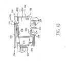
- the contact 208is inserted into housing 202 from the rear into cavities 212 ( Fig. 16 ).
- the contact 208is located (in the vertical sense of Fig. 18 ) by engagement of the bottom edge 215 ( Fig. 17 ) against surface 232 of the housing and by engagement of the top edges of the lugs 234 with the rib 236 in the upper part of the housing.
- the contactis maintained centered within the cavity 212 by the lateral tangs 222 that engage side walls of the cavity 212.
- the contact 208is longitudinally locked in the housing (in the direction of contact mating) by means of the spring arm 228 that is deflected downwardly by the rib 236 of the housing during insertion and then resiles upwardly to position the stop surface 230 at its distal end against or near the forward surface of the rib 236.
- the downwardly extending tang 224is preferably received in a slot 225 in the housing, the width of the slot being substantially the same as the thickness of the tang 224.
- the terminals 226extend below the bottom surface 238 of the housing 202, which bottom surface defines a mounting interface of the connector, along which it is mounted on a printed circuit board.
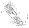
- Figs. 19 and 20show a receptacle connector for mating with the plug connector illustrated in Figs. 15-18 .
- the receptacle connectors 240include an insulative housing 242 that comprises an array of receptacle silos 244.
- the front surfaces 246 of the silosare substantially coplanar and form a mating interface of the connector.
- Each silohas an opening 248 for receiving the contact section 210 of the plug contacts 208 of the mating connector.
- the plurality of receptacle contacts 250are mounted in the housing 242, preferably by insertion from the rear into cavities 252. As shown in Fig. 20 , preferably the top wall 253 of the housing does not extend fully to the rear of the connector housing, thereby leaving substantial openings in the cavities 252.
- the receptacle contact for receptacle connector 240is illustrated in Fig. 21 .
- the contact 250is similar in basic form to the receptacle contact 48 illustrated in Figs. 3 and 4 . It includes two opposed walls 254, 256 that are preferably substantially planar and parallel, thereby forming between them a contact receiving and air flow space.
- the walls 254, 256are joined by a front bridging element 258 and a rear bridging element 260.
- the front bridging element 258includes a resilient latching arm that is cantilevered at its proximal end from bridging element 258 and carries at its distal end the latching or locking surface 264.
- the receptacle contact 250can be formed in a single, unitary piece, by stamping and forming the contact from a strip. As mentioned previously, the contacts can be inserted into the housing while attached to carrier strip S or after being separated therefrom.
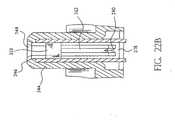
- Fig. 22is cross-sectional view showing a receptacle contact 250 inserted into housing 242.
- the locating tang 266is positioned with its forward surface against the locating surface 272 in the bottom wall of the housing 242, thereby positioning the contact in its forward- most position.
- the latching arm 262is caused to resile downwardly when it engages the latching portion 278 of the housing.
- the locking surface 264engages a raised rib 280 ( Fig. 22b ) thereby locking the contact against rearward movement with respect to the housing.
- the terminals 268extend beyond the surface 270 that forms the mounting interface of connector 240.
- the forward portions of the walls 254, 256are disposed along inside side walls of the silos 44.
- a plug contact receiving opening 248is formed at the forward surface 246 of each silo.
- the openingincludes a pair of lips 274 that are coplanar with or extend just slightly beyond the inside surfaces of the walls 254, 256. This arrangement provides the benefit of lowered initial insertion forces when the connectors 200 and 240 are mated.
- the contact sections 210 formed by the cantilevered arms 211first engage the surfaces of lips 274. Because the coefficient of friction between the cantilevered arms 22 and the plastic lips 274 is relatively lower than the coefficient friction between the cantilevered arms and the metal walls 254,256, initial insertion force is minimized.
- Fig. 23shows another embodiment of plug connector 290.
- the housing 292has a single front opening 294 in which the contact sections 296 of the plug contacts are disposed.
- the housingalso includes a plurality of openings 298 in the top wall of the housing.
- the bridging element 218 and locating lug 234engage the top surface 301 of the contact receiving cavity and the bottom surface 295 of the cavity in an interference fit.
- the arm 228deflects downwardly as the contact is inserted into the housing and the arm engages portion 303. When the arm 228 clears portion 303, the arm resiles upwardly to locate stop surface 230 adjacent surface 299, thereby locking the contact against retraction.
- Openings 298are positioned above the latching arms 228 ( Fig. 18 ), to allow the arm 228 to be moved from a retention position and the contacts to be withdrawn from the housing. This can be accomplished by insertion of a suitable tool (not shown) through opening 298. Openings 298 can also provide air flow passages for enhancing heat dissipation.
- Fig. 24illustrates a receptacle connector 300 adapted to mate with plug connector 290.
- the receptacle connector 300employs a housing 302 having a continuous front face 304, rather than a plurality of silos as in previous embodiments.
- the entire front face 304 of the connector 300is received in opening 294, with the contact sections 296 inserted into openings 305 of face 304.
- Openings 306 in the top wall of the housingallow access to the latching arms of the receptacle contacts (not shown) as described in the previous embodiment.
- the embodiment of Fig. 24 and also the embodiment of Figs. 25 and 26are meant for use in a vertical configuration, as opposed to a right angle configuration.
- the housing 302 of connector 300( Fig. 24 ) has a bottom side 307.
- a plurality of standoff surfaces 309form a mounting interface, along which the housing is mounted on a substrate, such as a printed circuit board.
- the housing of connector 320has a bottom surface 321 with standoffs 323.
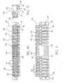
- Appropriate receptacle contacts 322( Fig. 7 ) are inserted into the housings of connectors 300 and 320 from the bottom sides 307 and 321, respectively.
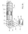
- Fig. 29shows an embodiment employing two sets of contacts at each location, in a stacked configuration.
- the receptacle connector 340has a housing formed of insulative material.
- the housing 342includes a mating interface having a plurality of openings 341.
- Each of the openings 341open into cavities in housing, which cavities receive substantially identical receptacle contacts 344a and 344b.
- Each of the contacts 344a and 344bis similar in general construction to the receptacle contacts previously described, there being a pair of such contacts in each cavity, generally aligned along the side walls thereof, to form a gap between generally parallel plate sections 346.
- the plate sections 346have two opposed edges 348 and 350, one of which carries a retention feature, such as interference bump 352.
- the receptacle contact sections 356are retained in the housing by suitable means, such as an interference fit created by the bump 352.
- Each contact section 356includes a generally coplanar wall section 354.
- the wall sections 354are joined by a bridge section 355.
- Suitable terminals, such as press fit terminals 356extend from an edge of the wall section 354, in the case where the connector 340 is to be used in a vertical configuration.
- the mating plug connector 360includes a molded polymeric body 361 that receives a pair of plug contacts, such as upper plug contact 362 and the lower plug contact 376. These plug contacts are configured generally in the manner previously described, namely, being formed of a pair of spaced wall sections 364 and 368 respectively joined by bridging elements and carrying opposed contact beams 366 and 380 to engage the spaced receptacle plates 346.
- the plug contact 362includes a single, relatively long, or several, relatively short, bridging elements 365 that join two opposed plates 364.
- the bottom edge 372 of each of the plates 364includes retention structure, such as an interference bump 374.
- the plug contact 362is retained in its cavity within housing 361 by an interference fit between the bridging elements 365 and the interference bump 374, although it is contemplated that other retention mechanisms could be utilized.
- lower plug contacts 376comprise a pair of coplanar wall or panel members 368 joined by one or more bridging elements 382.
- the lower edge 384 of each wall 368includes an interference bump 386, that functions to create an interference fit, as previously described.
- Suitable terminals 378 and 388extend from each of the panels 364 and 368, beyond the mounting interface 363 of the housing 361, for associating each of the contacts 362 and 376 with electrical tracks on the printed circuit board on which the plug 360 is to be mounted.
- the previously described receptacle and plug contactsmay be plated or otherwise coated with corrosion resistant materials. Also, the plug contact beams may be bowed slightly in the transverse direction to enhance engagement with the contact receiving surfaces of the receptacle contacts.
- both receptacle and blade contactsemploying opposing, relatively thin walls, allows for greater heat dissipation as compared with prior "singular-mass" designs.
- the enhanced heat dissipation propertiesresult from the contacts having greater surface area available for convection heat flow, especially through the center of the mated contacts. Because the plug contacts have an open configuration, heat loss by convection can occur from interior surfaces by passage of air in the gap between these surfaces.
- the contactsalso contain outwardly directed, mutually opposing receptacle beams and dual, peripherally located, mating blades, in a configuration which can allow for flexibility in modifying contact normal forces by adjustment the contact connector geometry. This can be accomplished by modifying the bridging elements to change bend radius, angle, or separation of the walls of the contacts. Such modifications cannot be accomplished with conventional singular-mass beam/blade configurations wherein the opposing receptacle contacts are inwardly directed, and the mating blade is located in the center of said beams.
- a compliant plug mating sectionallows the receptacle contacts to be placed in a protected position within the molded polymeric housing for safety purposes. This feature is of further benefit because it allows minimization of amount of polymeric material used in making the housing. This lowers material costs and enhances heat dissipation. Also, by retaining the contacts in the housing in the manner suggested, thick wall structures can be avoided and thin, fin like structures can be utilized, all of which enhances heat dissipation from the connectors. Additionally, first-make, last break functionality can be incorporated easily into disclosed connector system by modifying the length of the mating portion of the plug contacts or by changing the length of the plug-receiving portion of the receptacle contacts.
- plug and receptacle contactsmay be manufactured from closely similar or identical blanks thereby minimizing tooling requirements. Further, the plug or receptacle connectors can easily be associated with cables, by means of paddle boards.
- any of the power connectors previously described hereincan be modified to accommodate connections for an external AC power supply.
- the insulative housing of the receptacle connector shown in Figure 10which has been previously described as providing for the ability to provide for signal and power connections, can be extended to accommodate additional openings for incorporation of contact terminals therein, which terminals provide connection to the external AC power input terminals.
- An illustrative embodimentis shown in Figures 30-32 , which shows a signal and power receptacle connector 400 of the type described in U.S. Patent Application 09/160,900 , incorporating AC power cable connections.
- each of the AC power contact openings 412Disposed and retained within each of the AC power contact openings 412 is a corresponding AC power spade terminal 414.
- the AC power contact openingsare sized and configured to receive the AC spade terminals 414 with an interference fit and in a preferred embodiment the terminals are retained in the housing in a manner described below.
- the AC power spade terminal 414further includes cable plug projection 428.
- Cable plug projection 428comprises a pair of opposed cantilever beams 430, 432 with each such beam being integrally joined to proximal portion 434, which integrally joins a respective beam to a respective side wall.
- the AC power spade terminalis stamped or otherwise formed as a single unitary piece from a strip of suitable contact materials such as phosphor bronze alloys or beryllium copper alloys.
- the spade terminal, or portions thereof,may be plated or otherwise coated with corrosion resistant materials
- each AC power spade terminalprovides for engagement with a corresponding quick connect socket on the end of a corresponding AC power cable wire lead.
- These quick connect socketsare known in the art.
- the cantilevered beams 430 and 432are closely spaced together, particularly at their respective proximal and distal ends, in a state prior to engagement with the quick connect socket and each of the cantilevered beams has a slight arc near the mid-point of the beam, as shown in Figure 34 .
- the configuration of the beams 430 and 432 in this mannercreates a spring-like effect upon engagement of the cable plug projection 428 into the quick connect socket of the cable wires.
- each of the AC power spade terminals 414extends a significant distance beyond the rear face 436 of the connector housing 402 so that the cable plug projection of each spade terminal can be mated with a corresponding quick connect socket of an AC power cable wire.
- a protective shroud 438may be joined to the connector housing to cover the spade terminals connections, as shown in Figure 30 .
- the shroudhas two rear projections 440 and 442 that protrude from the rear face 444 of the shroud 438. To seat the shroud in place over the spade terminal contacts, the two rear projections 440 and 442 of the shroud are inserted into corresponding slots 446 and 448 in the connector housing 402.
- the shroudalso has three slotted openings 450, 452, and 454 that are formed in the rear face 444 and the bottom face 456 of the shroud.
- the slotted openings 450, 452, and 454receive a corresponding AC power spade terminal 414 such that the spade terminal becomes enshrouded by the shroud casing 456 when the shroud is seated into position onto the connector housing 402.
- the shroudalso incorporates polarization hubs 458 and 460 to ensure a proper orientation of the shroud onto the connector housing.
- the shroudmay be made of any suitable molded plastic material.
- the connectors described thus farhave been illustrated with three AC power spade terminals incorporated into the connector housing for receiving an external AC power supply connection.
- the present inventionis not intended to be limited in this manner and the connector could be designed to accommodate six or more spade terminals for receiving any corresponding number of AC power supply connections.
- the present inventionis not intended to be limited to the particular design of the AC power spade terminals described herein, nor the configuration of the spade terminals inside the connector housing.
- direct incorporation of external AC power supply connections into connectors of the type otherwise described hereincan be achieved for a wide variety of connector housings, such as the right angle power connectors and the vertical power connectors described herein.
- a retention mechanism for retaining the AC power spade terminal 416 within the connector housing 402is shown in Figures 30 and 32-33 .
- This form of retention mechanismdiffers from that shown for the contacts illustrated in Figure 17 , for example, where the retention mechanism is a retention arm 228.
- the contactis retained in the connector housing 402 by engagement of a locking bar onto the contact. More specifically, the AC power spade terminal has a gap 462 formed between the rearward arcuate bridging element 422 and opposing tangs 464.
- the locking bar 468is integrally formed as part of the shroud 438 so that when the shroud is positioned onto the connector housing 402 the locking bar 468 is seated into position in the slotted recess 466.
- the AC power spade terminalis otherwise engaged within the connector housing 402 by a friction fit between the spade terminal and the connector housing.
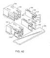
- FIG 42shows a connector incorporating a preferred embodiment of new contacts for connection to a bus bar 496 having opposing arms 498 of U-shaped projections.
- Bus bar terminal contacts 500are disposed in connector housing 502.
- the rear portion of the bus bar terminal contactsis similar in many respects to that of the plug contacts 10 and the receptacle contacts 48 shown in Figures 1-4 in that the bus bar terminal contacts have two opposed major side walls 504 and 505, which side walls define a medial space 507 adapted for air flow.
- the bus bar terminal contactsare retained in the housing by the engagement of a spring arm 506 in a slot 508 in the housing.
- the front portion of the bus bar terminal contactscomprises a clip 510 for engagement onto one of the arms 498 of the U-shaped projections.
- the clip 510has two opposing clip side walls 512 and 514, which clip side walls are engaged onto the arm 498.
- the clip side walls 512 and 514are bowed slightly in the transverse direction to enhance engagement with the arm 498.
- Each clip side wallhas wing tabs 516 that are joined to the side wall by arcuate elbow 518.
- the distance between the elbows 518 of the opposing side wallsis slightly less than the thickness of the arm 498 such that the elbows create an inward force on the arms when the clip 510 is engaged onto the arm.
- bus bar terminal contacts described hereincan be used in any connector for engagement of bus bars and are not intended to be limited for use in the connector housing configuration illustrated herein.
- any of the receptacle connectors described hereincan be modified to accommodate incorporation of bus bar terminal contacts for mating the power connectors herein with bus bars.
Landscapes
- Coupling Device And Connection With Printed Circuit (AREA)
- Connector Housings Or Holding Contact Members (AREA)
- Multi-Conductor Connections (AREA)
- Details Of Connecting Devices For Male And Female Coupling (AREA)
Abstract
Description
- 1.Field of the Invention: The present invention relates to electrical connectors and more particularly to electronic power connectors especially, useful in circuit board or backplane interconnection systems.
- 2.Brief Description of Prior Developments: Designers of electronic circuits generally are concerned with two basic circuit portions, the logic or signal portion and the power portion. In designing logic circuits, the designer usually does not have to take into account any changes in electrical properties, such as resistance of circuit components, that are brought about by changes in conditions, such as temperature, because current flows in logic circuits are usually relatively low. However, power circuits can undergo changes in electrical properties because of the relatively high current flows, for example, on the order of 30 amps or more in certain electronic equipment. Consequently, connectors designed for use in power circuits must be capable of dissipating heat (generated primarily as a result of the Joule effect) so that changes in circuit characteristics as a result of changing current flow are minimized. Conventional plug contacts in circuit board electrical power connectors are generally of rectangular (blade-like) or circular (pin-like) cross-section. These are so-called "singular-mass" designs. In these conventional singular-mass blade and pin configurations, the opposing receptacle contacts comprise a pair of inwardly urged cantilever beams and the mating blade or pin is located between the pair of beams. Such arrangements are difficult to reduce in size without adversely effecting heat dissipation capabilities. They also provide only minimal flexibility to change contact normal forces by adjustment of contact geometry.
- There is a need for a small contact which efficiently dissipates heat and which has readily modifiable contact normal forces.
- In
United States Patent Application 09/160,900 - It should be noted that
DE 34 41 416 describes an electrical plug connector which consists essentially of a male strip and of a female strip, the latter of which is provided with a large number of essentially identical chambers in which contact elements are accommodated and held which have spring parts, which form a plug region, and connecting parts, which form a connecting region. DE 40 01 104 describes a connector which comprises plugs and sockets, at least one of which has a conductive connector, which has an isolating housing which can be snap fitted together by snap fittings. The part with the connector is formed of a number of elements corresponding to a number of poles and each having a contact and a connector and a frame with a receiving chamber for each element.DE 23 50 834 describes an electrical power coupling with at least one plug contact disposed in a chamber of an insulating body, the plug contact being made of spring tape material and having one end configured as a flat plug tongue and the other end configured as a fork contact spring for electrically conductive receiving a flat plug.- Further attention is drawn to
EP 0 951 102 A2claim 1. - The present invention relates to an electrical connector according to
claim 1. - An electrical power connector is described herein that incorporates contacts for establishing AC power cable connections into a single housing along with the power connector contacts that are otherwise described herein. Incorporation of AC power cable connections directly into the insulative housing that forms the internal power connector eliminates the need for any transitional type, stand-alone AC power supply connection system such as that described above. The connector housing incorporating the AC power connection capability can accommodate different forms of AC power supply termination contacts, such as spade-type contacts for receiving discrete fast-on terminals or contacts described herein for connection to bus bars.
- The present invention is further described with reference to the accompanying drawings in which:
Fig. 1 is a perspective view of a plug contact;Fig. 2 is a side elevational view of the plug contact shown inFig. 1 ;Fig. 3 is a perspective view of a receptacle contact;Fig. 4 is a side elevational view of the receptacle contact shown inFig. 3 ;Fig. 5 is a front elevational view of a plug connector;Fig. 6 is a top plan view of the plug connector shown inFig. 5 ;Fig. 7 is an end view of the plug connector shown inFig. 5 ;Fig. 8 is a top front perspective view of the plug connector shown inFig. 5 ;Fig. 9 is a top rear perspective view of the plug connector shown inFig. 5 ;Fig. 10 is a front elevational view of a receptacle connector;Fig. 11 is a top plan view of the receptacle connector shown inFig. 10 ;Fig. 12 is an end view of the receptacle connector shown inFig. 10 ;Fig. 13 is a top front respective view of the receptacle connector shown inFig. 10 ;Fig. 14 is a top rear respective view other receptacle connector shown inFig. 1 .Fig. 15 is a front perspective view of a second embodiment of plug connector;Fig. 16 is a rear perspective view of the plug connector ofFig. 15 ;Fig. 17 is an isometric view of a plug contact used in the connector ofFig. 15 , with the contact still attached to a portion of the strip material from which its formed;Fig. 18 is a side cross-sectional view of the plug connector ofFig. 15 ;Fig. 19 is a front perspective view of a receptacle connector matable with the plug connector ofFig. 15 ;Fig. 20 is a rear perspective view of the receptacle connector shown inFig. 19 ;Fig. 21 is a isometric view of a receptacle contact used in the connector shown inFig. 19 , with the contact still attached to a portion of the metal strip from which it was formed;Fig. 22 is a side cross-sectional view of the receptacle connector shown inFig. 19 ;Fig. 22a is a partial cross-sectional view taken along line AA ofFig. 22 ;Fig. 22b is a partial cross-sectional view taken along line BB ofFig. 22 ;Fig. 23 is a front perspective view of a third embodiment of plug connector;Fig. 23a is a cross-sectional view of an alternative arrangement for securing a contact in a housing;Fig. 24 is a front perspective view of a receptacle connector adapted to mate with the plug connector withFig. 23 ;Fig. 25 is a front elevational view of another embodiment of receptacle connector;Fig. 26 is a bottom respective view of the connector shown inFig. 25 ;Fig. 27 is an isometric view of a receptacle contact used in the connectors illustrated in theFigs. 25 and 26 ;Fig. 28 is a cross-sectional view of a connector as shown inFig. 25 ; andFig. 29 is a cross-sectional view of an embodiment employing stacked contacts in the plug and receptacle connectors.Figure 30 is a top front perspective view of a receptacle connector incorporating AC power cable connections, including a spade terminal shroud.Figure 31 is a top plan view of the receptacle connector shown inFigure 30 .Figure 32 is a side cross-sectional view taken along line AA ofFigure 31 .Figure 33 is a perspective view of a spade terminal.Figure 34 is an enlarged view of the cable plug-up portion of the spade terminal shown inFigure 33 .Figure 35 is a side plan view of a shroud for the AC power supply spade terminals.Figure 36 is a bottom plan view of the shroud shown inFigure 35 .Figure 37 is a bottom cross-sectional view taken along line AA ofFigure 35 .Figure 38 is a top plan view of another receptacle connector incorporating AC power cable connections.Figure 39 is a side plan view of the connector shown inFigure 38 .Figure 40 is a top front perspective view of the connector shown inFigure 38 .Figure 41 is an exploded perspective view of the connector shown inFigure 38 , including a mounting bracket.Figure 42 is a perspective view of a connector incorporating contacts according to a preferred embodiment of the invention for connection to a bus bar.- Referring to
Figs. 1 and 2 , aplug contact 10 for use in a plug connector is shown. This plug contact has two opposedmajor side walls numeral 16, has anupper section 18 and alower section 20. Each of these upper and lower sections comprises a pair of opposed cantilever beams, each beam having inwardly convergingproximal section 22,arcuate contact section 24 and adistal section 26. The opposeddistal sections 26 are preferably parallel to each other. The distal sections can be positioned slightly apart when the beams are in relaxed condition, but come together when the beams are deflected as the front projection is inserted into a receptacle contact (as explained below). This provides over-stress protection for the beams during mating. The side walls also includeplanar panels Terminals panel 28.Terminal 40 extends frompanel 30, along with a plurality of like terminals (not shown). Terminals 32-40 can comprise through hole, solder-to-board pins (as shown), press fit pins or surface mount tails. Thepanels arcuate bridging elements medial space 46, adapted for airflow, is defined between thepanels contact 10 is stamped or otherwise formed as a single piece from a strip of suitable contact materials such as phosphor bronze alloys or beryllium copper alloys. - Referring to
Figs. 3 and 4 ,receptacle contact 48 is shown. This receptacle contact has opposed, preferably planar andparallel side walls front projecting portion 54, that forms a medialplug receiving space 56. The distance betweenwalls portion 54 is such that theprojection 16 of theplug contact 10 is receivable in the plugcontact receiving space 56, with the beams being resiliently deflected toward the center plane ofcontact 10. The deflection causes the beams to develop outwardly directed forces, thereby pressing thearcuate portions 24 against the inside surfaces of theportions 54 forming the receivingspace 56, to develop suitable contact normal force. Theside walls panels panel 58 there areterminals panel 60 there is terminal 70 as well as several other terminals (not shown). These terminals are essentially the same as previously described terminals 32-40. Theside walls arcuate bridging elements Figs. 5-9 illustrate aplug connector 75 having aninsulative plug housing 76. Thehousing 76 includes afront side 78 having a plurality ofpower contact apertures Figs. 1and 2 ) of the plug contacts is disposed inapertures plug contacts 10 are retained in thehousing 76 by an interference fit between the contact and the housing. This is accomplished by having the dimension H (Fig. 2 ), the dimension between bottom edge ofwall 12 and the top of bridgingelement 42, slightly greater than the dimension of the cavity inhousing 76 that receives this portion ofplug contact 10. Thefront side 78 may also include a signal pin array opening 88 for housing a signal pin array designated generally asnumeral 90. Thehousing 76 also includes a number of rear vertical partitions, such aspartitions contact retaining slots 96 for housing theplug contacts 98. The opposed medialvertical partitions pin array space 104 for housing therear portion 106 of the signal pins. Thehousing 76 also includes opposedrear mounting brackets apertures plug contacts 10 haveterminals bottom edge 80 ofhousing 76. Theedge 80 forms a mounting interface, along which the housing is mounted to a printed circuit board or other structure on which the connector is mounted.- Referring to
Figs. 10-14 , areceptacle connector 128 is shown.Receptacle 128 has aninsulative housing 129 with afront side 130 including a plurality ofsilos 131 having contact openings, such asopenings front side 130 forms a mating interface of theconnector 128 for mating withplug connector 75. Thesilos 131 are configured and sized to be received inopenings connector 75. The front portions 54 (Figs. 3-4 ) of the receptacle contacts are disposed withinsilos 131 andopenings lower sections plug contacts 10. Thefront side 130 has a signalpin receiving area 140 with signal pin receiving apertures. Thehousing 129 also has a plurality of rear partitions, such aspartitions contact retaining slots 148 forhousing receptacle contacts 48.Signal pin housing 152 receives a signalreceptacle contact array 154. Thehousing 129 also includes opposedrear mounting brackets apertures receptacle contact terminals surface 137, that forms the mounting interface ofreceptacle connector 128.. Thefront side 130 of thehousing 128 also has a plurality ofvertical spaces silos 131. - The
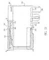
receptacle contacts 48 are retained inhousing 129 by an interference fit in essentially the same manner as previously described with respect to plugcontacts 10. Retaining the contacts in this fashion allows substantial portions of thewalls walls respective housings Fig. 15 shows anotherplug connector 200 embodying the invention. In this embodiment, thehousing 202, preferably formed of a molded polymeric material, has afront face 204 that forms the mating interface of the connector. Theface 204 includes a plurality of openings, such asopenings 206, formed in a linear array.- Referring to
Fig. 16 , theplug connector 200 includes a plurality ofplug contacts 208. Thecontacts 208 are inserted from the rear of the housing intocavities 212 that extend from the rear of the housing toward the front of the housing. When thecontacts 208 are fully inserted into thehousing 202, thecontact portions 210 withcontacts 208 are disposed in theopenings 206. - Referring to
Fig. 17 , theplug contact 208 is similar in many respects to the plug contacts shown inFig. 1 . It includes spaced panel-like walls walls front bridging element 218 and arear bridging element 220. In this embodiment, thecontact section 210 is formed by two opposedcantilevered beams 211 that extend from front edges of thewalls tang 224 formed along a bottom of the edge of the wall. Thewalls bent tangs 222, for centering the contact withincavities 212 inhousing 202. Each wall also includes a positioning feature, such as raisedlug 234. - The
front bridging element 218 includes a rearwardly extendingretention arm 228 that is cantilevered at its proximal end from the bridging element.Arm 228 includes a locatingsurface 230 at its distal end. - Terminals, such as through-
hole pins 226, extend from the bottom edge of eachwall terminals 226 can be solder-to-board pins (as shown) or can comprise press fit or other types of terminals. - As can be seen from
Fig. 17 , thecontacts 208 can be formed from sheet stock by stamping and forming the part from a strip of metallic stock suitable for forming electrical contacts. Thecontacts 208 can be retained on a carrier strip S for gang insertion or separated from the strip_prior to insertion into a housing. - Referring to
Fig. 18 , thecontact 208 is inserted intohousing 202 from the rear into cavities 212 (Fig. 16 ). Thecontact 208 is located (in the vertical sense ofFig. 18 ) by engagement of the bottom edge 215 (Fig. 17 ) againstsurface 232 of the housing and by engagement of the top edges of thelugs 234 with therib 236 in the upper part of the housing. The contact is maintained centered within thecavity 212 by the lateral tangs 222 that engage side walls of thecavity 212. Thecontact 208 is longitudinally locked in the housing (in the direction of contact mating) by means of thespring arm 228 that is deflected downwardly by therib 236 of the housing during insertion and then resiles upwardly to position thestop surface 230 at its distal end against or near the forward surface of therib 236. - The downwardly extending
tang 224 is preferably received in aslot 225 in the housing, the width of the slot being substantially the same as the thickness of thetang 224. By capturing thetang 224 in theslot 225, deformation of the wall section, as might occur when thecantilever arms 211 of the contact section are urged toward each other, is limited to the portion of thewalls tangs 224. This enhances control of the contact normal forces generated by deflection of thecantilever arms 211. - As shown in
Fig. 18 , theterminals 226 extend below thebottom surface 238 of thehousing 202, which bottom surface defines a mounting interface of the connector, along which it is mounted on a printed circuit board. Figs. 19 and 20 show a receptacle connector for mating with the plug connector illustrated inFigs. 15-18 . Thereceptacle connectors 240 include aninsulative housing 242 that comprises an array ofreceptacle silos 244. Thefront surfaces 246 of the silos are substantially coplanar and form a mating interface of the connector. Each silo has anopening 248 for receiving thecontact section 210 of theplug contacts 208 of the mating connector. The plurality ofreceptacle contacts 250 are mounted in thehousing 242, preferably by insertion from the rear intocavities 252. As shown inFig. 20 , preferably thetop wall 253 of the housing does not extend fully to the rear of the connector housing, thereby leaving substantial openings in thecavities 252.- The receptacle contact for
receptacle connector 240 is illustrated inFig. 21 . Thecontact 250 is similar in basic form to thereceptacle contact 48 illustrated inFigs. 3 and 4 . It includes two opposedwalls walls front bridging element 258 and arear bridging element 260. Thefront bridging element 258 includes a resilient latching arm that is cantilevered at its proximal end from bridgingelement 258 and carries at its distal end the latching or lockingsurface 264. As described previously, thereceptacle contact 250 can be formed in a single, unitary piece, by stamping and forming the contact from a strip. As mentioned previously, the contacts can be inserted into the housing while attached to carrier strip S or after being separated therefrom. Fig. 22 is cross-sectional view showing areceptacle contact 250 inserted intohousing 242. As shown, the locatingtang 266 is positioned with its forward surface against the locatingsurface 272 in the bottom wall of thehousing 242, thereby positioning the contact in its forward- most position. As the contact is inserted in the housing, the latchingarm 262 is caused to resile downwardly when it engages the latchingportion 278 of the housing. As the latchingarm 262 resiles upwardly after it passes thelatching section 278, the lockingsurface 264 engages a raised rib 280 (Fig. 22b ) thereby locking the contact against rearward movement with respect to the housing. Theterminals 268 extend beyond thesurface 270 that forms the mounting interface ofconnector 240.- As illustrated in
Figs. 22a and22b , the forward portions of thewalls silos 44. At theforward surface 246 of each silo, a plugcontact receiving opening 248 is formed. The opening includes a pair oflips 274 that are coplanar with or extend just slightly beyond the inside surfaces of thewalls connectors silos 244 enter the openings 206 (Fig. 15 ), thecontact sections 210 formed by the cantileveredarms 211 first engage the surfaces oflips 274. Because the coefficient of friction between the cantileveredarms 22 and theplastic lips 274 is relatively lower than the coefficient friction between the cantilevered arms and the metal walls 254,256, initial insertion force is minimized. Fig. 23 shows another embodiment ofplug connector 290. In this embodiment, thehousing 292 has asingle front opening 294 in which thecontact sections 296 of the plug contacts are disposed. The housing also includes a plurality ofopenings 298 in the top wall of the housing. As shown inFig. 23a , the bridgingelement 218 and locatinglug 234 engage thetop surface 301 of the contact receiving cavity and thebottom surface 295 of the cavity in an interference fit. Thearm 228 deflects downwardly as the contact is inserted into the housing and the arm engagesportion 303. When thearm 228 clearsportion 303, the arm resiles upwardly to locatestop surface 230adjacent surface 299, thereby locking the contact against retraction. Theopenings 298 are positioned above the latching arms 228 (Fig. 18 ), to allow thearm 228 to be moved from a retention position and the contacts to be withdrawn from the housing. This can be accomplished by insertion of a suitable tool (not shown) throughopening 298.Openings 298 can also provide air flow passages for enhancing heat dissipation.Fig. 24 illustrates areceptacle connector 300 adapted to mate withplug connector 290. Thereceptacle connector 300 employs ahousing 302 having a continuousfront face 304, rather than a plurality of silos as in previous embodiments. The entirefront face 304 of theconnector 300 is received inopening 294, with thecontact sections 296 inserted intoopenings 305 offace 304.Openings 306 in the top wall of the housing allow access to the latching arms of the receptacle contacts (not shown) as described in the previous embodiment.- The embodiment of
Fig. 24 and also the embodiment ofFigs. 25 and 26 are meant for use in a vertical configuration, as opposed to a right angle configuration. Thehousing 302 of connector 300 (Fig. 24 ) has abottom side 307. Preferably, a plurality of standoff surfaces 309 form a mounting interface, along which the housing is mounted on a substrate, such as a printed circuit board. Similarly, the housing ofconnector 320 has abottom surface 321 withstandoffs 323. Appropriate receptacle contacts 322 (Fig. 7 ) are inserted into the housings ofconnectors bottom sides Fig. 27 shows areceptacle contact 322 comprising a pair of preferably planarparallel walls terminals 328 extending from a rear edge of each of the walls. As shown inFig. 28 , thecontact 322 is received inhousing 330 in a manner similar to that previously described, wherein the resilient latching arm locks the contact against downward (in the sense ofFig. 28 ) movement, while a locatingsurface 334 locates the contact in the opposite direction with respect to the housing. Theterminals 328 extend beyond the plane of the mounting interface of the connector housing for insertion into through holes in the printed circuit board.Fig. 29 shows an embodiment employing two sets of contacts at each location, in a stacked configuration. Thereceptacle connector 340 has a housing formed of insulative material. Thehousing 342 includes a mating interface having a plurality ofopenings 341. Each of theopenings 341 open into cavities in housing, which cavities receive substantiallyidentical receptacle contacts contacts parallel plate sections 346. Theplate sections 346 have two opposededges receptacle contact sections 356 are retained in the housing by suitable means, such as an interference fit created by the bump 352. Eachcontact section 356 includes a generallycoplanar wall section 354. Thewall sections 354 are joined by abridge section 355. Suitable terminals, such as pressfit terminals 356 extend from an edge of thewall section 354, in the case where theconnector 340 is to be used in a vertical configuration.- The
mating plug connector 360 includes a moldedpolymeric body 361 that receives a pair of plug contacts, such asupper plug contact 362 and thelower plug contact 376. These plug contacts are configured generally in the manner previously described, namely, being formed of a pair of spacedwall sections receptacle plates 346. Theplug contact 362 includes a single, relatively long, or several, relatively short, bridgingelements 365 that join twoopposed plates 364. Thebottom edge 372 of each of theplates 364 includes retention structure, such as aninterference bump 374. Theplug contact 362 is retained in its cavity withinhousing 361 by an interference fit between the bridgingelements 365 and theinterference bump 374, although it is contemplated that other retention mechanisms could be utilized. Similarly,lower plug contacts 376 comprise a pair of coplanar wall orpanel members 368 joined by one or more bridging elements 382. Thelower edge 384 of eachwall 368 includes aninterference bump 386, that functions to create an interference fit, as previously described.Suitable terminals panels interface 363 of thehousing 361, for associating each of thecontacts plug 360 is to be mounted. - The previously described receptacle and plug contacts may be plated or otherwise coated with corrosion resistant materials. Also, the plug contact beams may be bowed slightly in the transverse direction to enhance engagement with the contact receiving surfaces of the receptacle contacts.
- The "dual-mass" construction of both receptacle and blade contacts, employing opposing, relatively thin walls, allows for greater heat dissipation as compared with prior "singular-mass" designs. The enhanced heat dissipation properties result from the contacts having greater surface area available for convection heat flow, especially through the center of the mated contacts. Because the plug contacts have an open configuration, heat loss by convection can occur from interior surfaces by passage of air in the gap between these surfaces.
- The contacts also contain outwardly directed, mutually opposing receptacle beams and dual, peripherally located, mating blades, in a configuration which can allow for flexibility in modifying contact normal forces by adjustment the contact connector geometry. This can be accomplished by modifying the bridging elements to change bend radius, angle, or separation of the walls of the contacts. Such modifications cannot be accomplished with conventional singular-mass beam/blade configurations wherein the opposing receptacle contacts are inwardly directed, and the mating blade is located in the center of said beams.
- Such dual, opposing, planar contact construction also allows for easier inclusion of additional printed circuit board attachment terminals with more separation between terminals, compared to an equivalent "singular-mass" bulk designs. The use of relatively larger plates in the plug and receptacle contacts gives this opportunity for providing a plurality of circuit board terminals on each contact part. These lessens constriction of current flow to the printed circuit board, thereby lowering resistance and lessening heat generation.
- The use of a compliant plug mating section allows the receptacle contacts to be placed in a protected position within the molded polymeric housing for safety purposes. This feature is of further benefit because it allows minimization of amount of polymeric material used in making the housing. This lowers material costs and enhances heat dissipation. Also, by retaining the contacts in the housing in the manner suggested, thick wall structures can be avoided and thin, fin like structures can be utilized, all of which enhances heat dissipation from the connectors. Additionally, first-make, last break functionality can be incorporated easily into disclosed connector system by modifying the length of the mating portion of the plug contacts or by changing the length of the plug-receiving portion of the receptacle contacts.
- The arch connection structure between opposing rectangular contact sections also allows for attachment of retention means, such as a resilient arm structure as shown in one of the current embodiments, in a manner that does not limit current flow or hinder contact heat dissipation capability.
- It will also be appreciated that the plug and receptacle contacts may be manufactured from closely similar or identical blanks thereby minimizing tooling requirements. Further, the plug or receptacle connectors can easily be associated with cables, by means of paddle boards.
- Any of the power connectors previously described herein can be modified to accommodate connections for an external AC power supply. For example, the insulative housing of the receptacle connector shown in
Figure 10 , which has been previously described as providing for the ability to provide for signal and power connections, can be extended to accommodate additional openings for incorporation of contact terminals therein, which terminals provide connection to the external AC power input terminals. An illustrative embodiment is shown inFigures 30-32 , which shows a signal andpower receptacle connector 400 of the type described inU.S. Patent Application 09/160,900 , incorporating AC power cable connections. - The
receptacle connector 400 includes aninsulative housing 402 with afront side 404 including an array of contact openings, such asopenings Front side 404 also includes a signal receptacle in the form of signalpin receiving area 410 with signal pin receiving apertures. One of ordinary skill in the art will understand that the portion of thereceptacle connector 400 that includes thecontact openings pin receiving area 410 is similar in many respects to the connectors described previously. A receptacle contact, such as any one of those described previously, is disposed and retained within a corresponding opening of the receptacle housing. The connector is shown inFigure 30 with those contacts (and signal pins) other than the AC power supply contacts removed for clarity. In this regard, a connector including AC cable connections is not intended to be limited to any particular arrangement of the contacts and contact openings, as well as the configuration thereof, that have been described previously. - Included in the
front side 404 of thehousing 402 are three exemplary ACpower contact openings 412. Disposed and retained within each of the ACpower contact openings 412 is a corresponding ACpower spade terminal 414. The AC power contact openings are sized and configured to receive theAC spade terminals 414 with an interference fit and in a preferred embodiment the terminals are retained in the housing in a manner described below. Figures 33 and 34 show the ACpower spade terminal 414. Therear portion 416 of the terminal comprises two opposingmajor side walls Figures 1-4 . In a manner similar in many respects to the contacts described previously, theside walls spade terminal 414 are connected byarcuate bridging elements medial space 426, adapted for air flow, is defined betweenside walls power spade terminal 414. The ACpower spade terminal 414 further includescable plug projection 428.Cable plug projection 428 comprises a pair of opposed cantilever beams 430, 432 with each such beam being integrally joined toproximal portion 434, which integrally joins a respective beam to a respective side wall. The AC power spade terminal is stamped or otherwise formed as a single unitary piece from a strip of suitable contact materials such as phosphor bronze alloys or beryllium copper alloys. The spade terminal, or portions thereof, may be plated or otherwise coated with corrosion resistant materials- The
cable plug projection 428 of each AC power spade terminal according to the invention provides for engagement with a corresponding quick connect socket on the end of a corresponding AC power cable wire lead. These quick connect sockets are known in the art. The cantilevered beams 430 and 432 are closely spaced together, particularly at their respective proximal and distal ends, in a state prior to engagement with the quick connect socket and each of the cantilevered beams has a slight arc near the mid-point of the beam, as shown inFigure 34 . The configuration of thebeams cable plug projection 428 into the quick connect socket of the cable wires. The spring design feature of this spade terminal provides for a secure and positive locking engagement of the quick connect socket onto the AC power spade terminal and also provides more forgiveness in the mating between the plug projection and the quick connect socket in those circumstances where the quick connect socket is not flexible, such as where the quick connect sockets of the AC cable wires are molded inside a plastic connector housing. - The
cable plug projection 428 of each of the ACpower spade terminals 414 extends a significant distance beyond therear face 436 of theconnector housing 402 so that the cable plug projection of each spade terminal can be mated with a corresponding quick connect socket of an AC power cable wire. One of ordinary skill in the art will recognize that significant current levels will be maintained through the AC power spade terminals. In order to protect the spade terminal and quick connect socket connection from coming into inadvertent contact with a user that may be installing other components into the system, aprotective shroud 438 may be joined to the connector housing to cover the spade terminals connections, as shown inFigure 30 . Referring also toFigures 35-37 , the shroud has tworear projections rear face 444 of theshroud 438. To seat the shroud in place over the spade terminal contacts, the tworear projections slots connector housing 402. The shroud also has three slottedopenings rear face 444 and thebottom face 456 of the shroud. When therear projections slots openings power spade terminal 414 such that the spade terminal becomes enshrouded by theshroud casing 456 when the shroud is seated into position onto theconnector housing 402. The shroud also incorporatespolarization hubs - The connectors described thus far have been illustrated with three AC power spade terminals incorporated into the connector housing for receiving an external AC power supply connection. The present invention is not intended to be limited in this manner and the connector could be designed to accommodate six or more spade terminals for receiving any corresponding number of AC power supply connections. Also, the present invention is not intended to be limited to the particular design of the AC power spade terminals described herein, nor the configuration of the spade terminals inside the connector housing. Furthermore, direct incorporation of external AC power supply connections into connectors of the type otherwise described herein can be achieved for a wide variety of connector housings, such as the right angle power connectors and the vertical power connectors described herein.
- A retention mechanism for retaining the AC
power spade terminal 416 within theconnector housing 402 is shown inFigures 30 and32-33 . This form of retention mechanism differs from that shown for the contacts illustrated inFigure 17 , for example, where the retention mechanism is aretention arm 228. For the ACpower spade terminal 414 the contact is retained in theconnector housing 402 by engagement of a locking bar onto the contact. More specifically, the AC power spade terminal has agap 462 formed between the rearwardarcuate bridging element 422 and opposingtangs 464. When the AC power spade terminals are disposed into position with theconnector housing 402 the gaps in each of the corresponding terminals are exposed in a slottedrecess 466 in the connector housing such that thegaps 462 across the adjacent spade terminals are aligned with the slottedrecess 466. A lockingbar 468 of appropriate dimension is positioned into the slottedrecess 466 in theconnector housing 402 such that the locking bar is seated across thegaps 462 of the spade terminals between the respective rearwardarcuate bridging element 422 and thetangs 464 of each spade terminal. In a preferred embodiment as shown inFigure 30 the lockingbar 468 is integrally formed as part of theshroud 438 so that when the shroud is positioned onto theconnector housing 402 the lockingbar 468 is seated into position in the slottedrecess 466. This is not necessary and the locking bar could be a separate piece of plastic material or some other suitable material. The AC power spade terminal is otherwise engaged within theconnector housing 402 by a friction fit between the spade terminal and the connector housing. When the lockingbar 468 is seated into position within theconnector housing 402 engagement of the rearwardarcuate bridging element 422 against the locking bar prevents the AC power spade terminal from being pulled out of its engagement within the connector housing. - Another configuration of a power connector incorporating connections for an external AC power supply is shown in
Figures 38-41 . In this embodiment, the connector housing is designed for AC power spade terminals only. In this example, six ACpower spade terminals 470, similar to those described previously, are disposed inconnector housing 472. Again, the connectors are not intended to be limited to a design for six cable wires and the connector housing can be designed to accommodate any desired number of AC power spade terminals. Thetop face 473 of the connector housing exposes the opposing side walls of the receptacle end of the AC power spade terminals for mating with an appropriate header or plug connection. The AC power spade terminals are engaged in the connector housing by a friction fit as described previously and are retained in the housing by engagement with a lockingbar 474 in the same manner described above. In this embodiment, the lockingbar 474 is a separate piece. The connector housing is disposed within opposinghalves groove 480 extending around the perimeter of the casing. A mountingbracket 482, which is affixed to some component structure by the use of screws or the like throughholes 484, is designed such that opposingwings rail 490 fit into thegroove 480. Power connectors of the type described herein float or move with respect to each other when they are mated together due to the design of thepost projections 492 and the corresponding post-receiving holes in the mating connector. In order to accommodate the floatable characteristics of the mated power connectors described herein, the mounting bracket is dimensioned such that thewings rail 490 fit loosely within thegroove 480. As such, theconnector housing 472 can float from side-to-side and forward-to-backward while being otherwise maintained in place by the mountingbracket 482. One of the wings of the mounting bracket can have acutout 494 that loosely engages a tab on the connector housing as a polarization feature to ensure proper orientation of the mounting bracket onto the cable casing. Otherwise, the loose fitting nature of the mounting bracket into the groove of the cable casing provides for blind mating of cable connector into the mounting bracket. This is beneficial due to the crowding of various connections in the system, which connections may be at a remote location that is difficult to access for a user. - In some applications, power is supplied to the electronics assembly via conventional bus bars.
Figure 42 shows a connector incorporating a preferred embodiment of new contacts for connection to abus bar 496 having opposingarms 498 of U-shaped projections. Busbar terminal contacts 500 are disposed inconnector housing 502. The rear portion of the bus bar terminal contacts is similar in many respects to that of theplug contacts 10 and thereceptacle contacts 48 shown inFigures 1-4 in that the bus bar terminal contacts have two opposedmajor side walls medial space 507 adapted for air flow. The bus bar terminal contacts are retained in the housing by the engagement of aspring arm 506 in aslot 508 in the housing. The front portion of the bus bar terminal contacts comprises aclip 510 for engagement onto one of thearms 498 of the U-shaped projections. Theclip 510 has two opposingclip side walls 512 and 514, which clip side walls are engaged onto thearm 498. Theclip side walls 512 and 514 are bowed slightly in the transverse direction to enhance engagement with thearm 498. Each clip side wall haswing tabs 516 that are joined to the side wall byarcuate elbow 518. The distance between theelbows 518 of the opposing side walls is slightly less than the thickness of thearm 498 such that the elbows create an inward force on the arms when theclip 510 is engaged onto the arm. - The bus bar terminal contacts described herein can be used in any connector for engagement of bus bars and are not intended to be limited for use in the connector housing configuration illustrated herein. For example, any of the receptacle connectors described herein can be modified to accommodate incorporation of bus bar terminal contacts for mating the power connectors herein with bus bars.
- While the present invention has been described in connection with the preferred embodiments of the various figures, it is to be understood that other similar embodiments may be used or modifications and additions may be made to the described embodiment for performing the same function of the present invention without deviating therefrom. Therefore, the present invention should not be limited to any single embodiment, but rather construed in breadth and scope in accordance with the recitation of the appended claims.
Claims (11)
- A receptacle electrical connector (400) comprising
an insulative housing (402) having at least one conductive receptacle contact (48) wherein the housing comprises a front side (404) for engaging a complementary electrical connector, a rear face (436) opposite the front face and a mounting face arranged substantially at a right angle to the front side, forming a mounting interface along which the housing is mountable to a printed circuit board,
characterised in that the connector comprises a plurality of conductive plug contacts (414), each said plug contact having a cable plug projection (428) for mating with a corresponding removable contact of an AC power cable and wherein the cable plug projections extend beyond the rear face of the connector housing. - The connector (400) of claim 1, each said plug contact (414) further having a pair of spaced walls (418, 420) forming a plug contact receiving space (426) therebetween.
- The connector (400) of claim 2, wherein said at least one conductive receptacle contact (48) has a pair of spaced walls (50, 52) forming a plug contact receiving space (56) therebetween.
- The connector (400) of claim 1, wherein the cable plug projection (428) comprises a pair of opposed and spaced apart cantilever beams (430, 432).
- The connector (400) of claim 4, wherein each of the cantilever beams (430, 432) has an arc to impart a spring-like effect of said cable plug projection (428) when it is mated with a corresponding contact of an AC power cable.
- The electrical connector (400) of claim 1, wherein each said conductive plug contact (414) is formed as a single piece of an electrically conductive material.
- The connector (400) of claim 1, further comprising a shroud (438) enclosing therein said cable plug projection (428) of said plurality of conductive plug contacts.
- The electrical connector (400) of claim 7, wherein the protective shroud (438) defines polarization hubs (458, 460).
- The electrical connector (400) of claim 1, further comprising a locking bar (468) that connects to the insulative housing and retains the conductive electrical AC power spade terminal (414) by engagement onto the contact.
- The electrical connector (400) of claim 9, further comprising a shroud (438) enclosing therein said cable plug projection (428) of said plurality of conductive plug contacts, wherein the locking bar is integrally formed as part of the shroud.
- The connector of claim 1, wherein said insulative housing (402) further includes at least one signal contact therein.
Applications Claiming Priority (2)
| Application Number | Priority Date | Filing Date | Title |
|---|---|---|---|
| US09/944,266US20020098743A1 (en) | 1998-04-17 | 2001-08-31 | Power connector |
| EP02018300AEP1289070B1 (en) | 2001-08-31 | 2002-08-26 | Receptacle connector with a plug contact for mating with a bus bar power supply |
Related Parent Applications (2)
| Application Number | Title | Priority Date | Filing Date |
|---|---|---|---|
| EP02018300.0Division | 2002-08-26 | ||
| EP02018300ADivisionEP1289070B1 (en) | 2001-08-31 | 2002-08-26 | Receptacle connector with a plug contact for mating with a bus bar power supply |
Publications (3)
| Publication Number | Publication Date |
|---|---|
| EP1737076A2 EP1737076A2 (en) | 2006-12-27 |
| EP1737076A3 EP1737076A3 (en) | 2007-05-23 |
| EP1737076B1true EP1737076B1 (en) | 2012-04-11 |
Family
ID=25481090
Family Applications (4)
| Application Number | Title | Priority Date | Filing Date |
|---|---|---|---|
| EP06010999AWithdrawnEP1696515A1 (en) | 2001-08-31 | 2002-08-26 | Power connector |
| EP06018785AExpired - LifetimeEP1737076B1 (en) | 2001-08-31 | 2002-08-26 | Receptacle electrical connector |
| EP02018300AExpired - LifetimeEP1289070B1 (en) | 2001-08-31 | 2002-08-26 | Receptacle connector with a plug contact for mating with a bus bar power supply |
| EP05028210AExpired - LifetimeEP1648053B1 (en) | 2001-08-31 | 2002-08-26 | Power connector |
Family Applications Before (1)
| Application Number | Title | Priority Date | Filing Date |
|---|---|---|---|
| EP06010999AWithdrawnEP1696515A1 (en) | 2001-08-31 | 2002-08-26 | Power connector |
Family Applications After (2)
| Application Number | Title | Priority Date | Filing Date |
|---|---|---|---|
| EP02018300AExpired - LifetimeEP1289070B1 (en) | 2001-08-31 | 2002-08-26 | Receptacle connector with a plug contact for mating with a bus bar power supply |
| EP05028210AExpired - LifetimeEP1648053B1 (en) | 2001-08-31 | 2002-08-26 | Power connector |
Country Status (8)
| Country | Link |
|---|---|
| US (3) | US20020098743A1 (en) |
| EP (4) | EP1696515A1 (en) |
| JP (2) | JP4188035B2 (en) |
| KR (1) | KR100866243B1 (en) |
| CN (2) | CN100386923C (en) |
| AT (3) | ATE513332T1 (en) |
| DE (1) | DE60217594T2 (en) |
| TW (1) | TW576555U (en) |
Families Citing this family (117)
| Publication number | Priority date | Publication date | Assignee | Title |
|---|---|---|---|---|
| US20020098743A1 (en)* | 1998-04-17 | 2002-07-25 | Schell Mark S. | Power connector |
| US6319075B1 (en)* | 1998-04-17 | 2001-11-20 | Fci Americas Technology, Inc. | Power connector |
| WO2005065254A2 (en) | 2003-12-31 | 2005-07-21 | Fci Americas Technology, Inc. | Electrical power contacts and connectors comprising same |
| US7458839B2 (en)* | 2006-02-21 | 2008-12-02 | Fci Americas Technology, Inc. | Electrical connectors having power contacts with alignment and/or restraining features |
| SG121012A1 (en)* | 2004-10-01 | 2006-04-26 | Molex Inc | Heat dissipating terminal and elctrical connector using same |
| US7476108B2 (en) | 2004-12-22 | 2009-01-13 | Fci Americas Technology, Inc. | Electrical power connectors with cooling features |
| US7384289B2 (en) | 2005-01-31 | 2008-06-10 | Fci Americas Technology, Inc. | Surface-mount connector |
| JP2006244902A (en)* | 2005-03-04 | 2006-09-14 | Tyco Electronics Amp Kk | Electric connector and electric connector assembly |
| US7303427B2 (en) | 2005-04-05 | 2007-12-04 | Fci Americas Technology, Inc. | Electrical connector with air-circulation features |
| US7425145B2 (en) | 2006-05-26 | 2008-09-16 | Fci Americas Technology, Inc. | Connectors and contacts for transmitting electrical power |
| US7726982B2 (en) | 2006-06-15 | 2010-06-01 | Fci Americas Technology, Inc. | Electrical connectors with air-circulation features |
| WO2008047181A1 (en)* | 2006-10-20 | 2008-04-24 | Fci | Electrical connector |
| US7641500B2 (en) | 2007-04-04 | 2010-01-05 | Fci Americas Technology, Inc. | Power cable connector system |
| US7905731B2 (en) | 2007-05-21 | 2011-03-15 | Fci Americas Technology, Inc. | Electrical connector with stress-distribution features |
| JP4889118B2 (en)* | 2007-06-07 | 2012-03-07 | 株式会社ヨコオ | Electrical connector |
| US7762857B2 (en) | 2007-10-01 | 2010-07-27 | Fci Americas Technology, Inc. | Power connectors with contact-retention features |
| US20090109691A1 (en)* | 2007-10-24 | 2009-04-30 | Yung-Yi Chuang | Bent fixing structure for light emitting component |
| US7481677B1 (en)* | 2007-10-30 | 2009-01-27 | Hon Hai Precision Ind. Co., Ltd. | Electrical connector with electrostatic discharge protection |
| US8435047B2 (en)* | 2007-12-04 | 2013-05-07 | Molex Incorporated | Modular connectors with easy-connect capability |
| US7976317B2 (en)* | 2007-12-04 | 2011-07-12 | Molex Incorporated | Low profile modular electrical connectors and systems |
| CN102769224B (en)* | 2008-02-04 | 2014-10-22 | 凡甲电子(苏州)有限公司 | Power supply connector assembly |
| CN102723637B (en)* | 2008-02-04 | 2014-10-22 | 凡甲电子(苏州)有限公司 | Power supply connector assembly |
| KR100833532B1 (en)* | 2008-02-21 | 2008-05-29 | 주식회사 광명전기 | Motor control panel with improved carrying capacity and insulation |
| CN101567500B (en)* | 2008-04-21 | 2012-07-18 | 凡甲电子(苏州)有限公司 | Power connector and terminal supporting structure thereof |
| US7850466B2 (en)* | 2008-06-23 | 2010-12-14 | Tyco Electronics Corporation | Through board inverted connector |
| US7704082B2 (en)* | 2008-06-23 | 2010-04-27 | Tyco Electronics Corporation | Through board inverted connector |
| US8062051B2 (en) | 2008-07-29 | 2011-11-22 | Fci Americas Technology Llc | Electrical communication system having latching and strain relief features |
| JP5285997B2 (en)* | 2008-08-27 | 2013-09-11 | 矢崎総業株式会社 | Power supply |
| US8814605B2 (en)* | 2008-12-26 | 2014-08-26 | Alltop Electronics (Suzhou) Ltd. | Power connector |
| CN101764305B (en)* | 2008-12-26 | 2012-04-25 | 凡甲电子(苏州)有限公司 | Electric connector |
| USD610548S1 (en) | 2009-01-16 | 2010-02-23 | Fci Americas Technology, Inc. | Right-angle electrical connector |
| USD608293S1 (en) | 2009-01-16 | 2010-01-19 | Fci Americas Technology, Inc. | Vertical electrical connector |
| USD664096S1 (en) | 2009-01-16 | 2012-07-24 | Fci Americas Technology Llc | Vertical electrical connector |
| USD606497S1 (en) | 2009-01-16 | 2009-12-22 | Fci Americas Technology, Inc. | Vertical electrical connector |
| USD606496S1 (en) | 2009-01-16 | 2009-12-22 | Fci Americas Technology, Inc. | Right-angle electrical connector |
| USD640637S1 (en) | 2009-01-16 | 2011-06-28 | Fci Americas Technology Llc | Vertical electrical connector |
| USD616827S1 (en) | 2009-01-30 | 2010-06-01 | Fci Americas Technology, Inc. | Electrical connector |
| USD619099S1 (en) | 2009-01-30 | 2010-07-06 | Fci Americas Technology, Inc. | Electrical connector |
| US8323049B2 (en) | 2009-01-30 | 2012-12-04 | Fci Americas Technology Llc | Electrical connector having power contacts |
| CN101510639B (en)* | 2009-03-12 | 2012-08-29 | 中航光电科技股份有限公司 | Plug contact member and socket contact member of power supply connector |
| US8366485B2 (en) | 2009-03-19 | 2013-02-05 | Fci Americas Technology Llc | Electrical connector having ribbed ground plate |
| USD618180S1 (en) | 2009-04-03 | 2010-06-22 | Fci Americas Technology, Inc. | Asymmetrical electrical connector |
| USD618181S1 (en) | 2009-04-03 | 2010-06-22 | Fci Americas Technology, Inc. | Asymmetrical electrical connector |
| DE102009049853A1 (en)* | 2009-06-25 | 2010-12-30 | Hager Electro Gmbh & Co. Kg | Element for bridging spaced apart electrical conductors |
| US7892031B1 (en)* | 2009-07-30 | 2011-02-22 | Tyco Electronics Corporation | Quick insertion lamp assembly |
| JP5813302B2 (en) | 2009-09-07 | 2015-11-17 | 矢崎総業株式会社 | Bus bar module and power supply device including the bus bar module |
| DE102009047401A1 (en)* | 2009-12-02 | 2011-06-16 | Continental Automotive Gmbh | Connector, plug-in module and method of making an electrical connector |
| CN102714374B (en)* | 2009-12-21 | 2016-08-17 | Fci公司 | Connector assembly |
| WO2011118851A1 (en)* | 2010-03-25 | 2011-09-29 | Yazaki Corporation | Joint Connector and Method for Identifying Bus Bar Pattern in Joint Connector |
| DE102010014144C5 (en)* | 2010-04-07 | 2020-10-29 | Wago Verwaltungsgesellschaft Mbh | Electrical connection terminal |
| DE202010010275U1 (en) | 2010-07-15 | 2011-12-20 | Weidmüller Interface GmbH & Co. KG | Electrical contact part |
| EP2612400B1 (en)* | 2010-09-02 | 2014-07-16 | Yazaki Corporation | Busbar module and power supply unit including same busbar module |
| TW201232972A (en)* | 2010-10-15 | 2012-08-01 | Framatome Connectors Int | Electrical power connector system including power rail |
| US8262395B2 (en)* | 2010-12-27 | 2012-09-11 | Chief Land Electronic Co., Ltd. | Power connector assembly with improved terminals |
| CN102157833B (en)* | 2011-03-30 | 2012-12-26 | 中航光电科技股份有限公司 | Male end power contact element and rectangular electric connector with the same |
| EP2705575B1 (en)* | 2011-05-03 | 2017-04-12 | CardioInsight Technologies, Inc. | High-voltage resistance for a connector attached to a circuit board |
| DE102011050364B4 (en)* | 2011-05-13 | 2013-08-29 | Tyco Electronics Amp Gmbh | Plug contact element and plug contact arrangement for the transmission of frequencies in the gigahertz range |
| US8727796B2 (en)* | 2011-08-12 | 2014-05-20 | Fci Americas Technology Llc | Power connector |
| US8500465B1 (en)* | 2011-09-15 | 2013-08-06 | Amazon Technologies, Inc. | Adaptive cable connection system |
| CN103050812A (en)* | 2011-10-13 | 2013-04-17 | 凡甲电子(苏州)有限公司 | Electric connector |
| CN104319511B (en)* | 2011-10-24 | 2016-09-14 | 凡甲电子(苏州)有限公司 | Electric connector |
| CN103066412B (en)* | 2011-10-24 | 2015-02-18 | 凡甲电子(苏州)有限公司 | electrical connector |
| CN103078196A (en)* | 2011-10-25 | 2013-05-01 | 凡甲电子(苏州)有限公司 | Electric connector |
| CN103078197A (en)* | 2011-10-25 | 2013-05-01 | 凡甲电子(苏州)有限公司 | Electric connector |
| CN104779499A (en)* | 2012-01-04 | 2015-07-15 | 凡甲电子(苏州)有限公司 | Electric connector |
| CN103208694A (en)* | 2012-01-16 | 2013-07-17 | 凡甲电子(苏州)有限公司 | Electric coupler and assembly thereof |
| EP2624034A1 (en) | 2012-01-31 | 2013-08-07 | Fci | Dismountable optical coupling device |
| USD718253S1 (en) | 2012-04-13 | 2014-11-25 | Fci Americas Technology Llc | Electrical cable connector |
| USD727268S1 (en) | 2012-04-13 | 2015-04-21 | Fci Americas Technology Llc | Vertical electrical connector |
| US9257778B2 (en) | 2012-04-13 | 2016-02-09 | Fci Americas Technology | High speed electrical connector |
| US8944831B2 (en) | 2012-04-13 | 2015-02-03 | Fci Americas Technology Llc | Electrical connector having ribbed ground plate with engagement members |
| USD727852S1 (en) | 2012-04-13 | 2015-04-28 | Fci Americas Technology Llc | Ground shield for a right angle electrical connector |
| DE102012105508B4 (en)* | 2012-06-25 | 2016-11-10 | Wago Verwaltungsgesellschaft Mbh | Pin contact element and electronics housing |
| US9543703B2 (en) | 2012-07-11 | 2017-01-10 | Fci Americas Technology Llc | Electrical connector with reduced stack height |
| USD751507S1 (en) | 2012-07-11 | 2016-03-15 | Fci Americas Technology Llc | Electrical connector |
| US8902569B1 (en) | 2012-07-27 | 2014-12-02 | Amazon Technologies, Inc. | Rack power distribution unit with detachable cables |
| CN103594842A (en)* | 2012-08-17 | 2014-02-19 | 温州意华通讯接插件有限公司 | Power connector |
| US9065192B2 (en)* | 2013-09-19 | 2015-06-23 | Tyco Electronics Corporation | Power terminal connector |
| USD745852S1 (en) | 2013-01-25 | 2015-12-22 | Fci Americas Technology Llc | Electrical connector |
| US8968022B2 (en)* | 2013-02-25 | 2015-03-03 | Tyco Electronics Corporation | Electrical connector having poke-in wire contact |
| USD720698S1 (en) | 2013-03-15 | 2015-01-06 | Fci Americas Technology Llc | Electrical cable connector |
| EP2824767B1 (en)* | 2013-07-08 | 2019-10-09 | TE Connectivity Nederland B.V. | Busbar connection system for use with a power distribution system, and Electrical device including the bubar connection system |
| US9385500B2 (en)* | 2013-08-26 | 2016-07-05 | FCI Asia Pte. Ltd. | Electrical connector including fins |
| CN105765797B (en) | 2013-11-27 | 2019-07-05 | 安费诺富加宜(亚洲)私人有限公司 | Electric connector |
| CN103972689A (en)* | 2014-05-21 | 2014-08-06 | 四川永贵科技有限公司 | Inserting piece assembly of electric connector |
| CN104332764B (en)* | 2014-07-28 | 2017-06-27 | 中航光电科技股份有限公司 | Chip contact and electrical connector using the chip contact |
| JP6140129B2 (en)* | 2014-11-14 | 2017-05-31 | 古河電気工業株式会社 | Terminal block and terminal block unit |
| US9401558B1 (en)* | 2015-01-30 | 2016-07-26 | Alltop Electronics (Suzhou) Ltd. | Power connector |
| US10164387B2 (en) | 2015-02-09 | 2018-12-25 | Abb Schweiz Ag | Electrical device, electrical distribution system, and methods of assembling same |
| US9979164B2 (en)* | 2015-02-09 | 2018-05-22 | General Electric Company | Electrical distribution apparatus, system, and methods of assembling same |
| CN110632717A (en) | 2015-09-10 | 2019-12-31 | 申泰公司 | Rack mount equipment with high heat dissipation modules and transceiver sockets with increased cooling |
| TWM534451U (en)* | 2015-12-31 | 2016-12-21 | Alltop Technology Co Ltd | Power connector |
| FR3048559B1 (en)* | 2016-03-04 | 2018-03-09 | Schneider Electric Industries Sas | ELECTRICAL STRUCTURE FOR CONNECTING A BAR CONDUCTIVE TO AN ELECTRICAL COMPONENT |
| CN106025640B (en)* | 2016-05-11 | 2018-05-04 | 杭州欣驰能源科技有限公司 | A kind of power connector |
| CA3033379A1 (en) | 2016-08-22 | 2018-03-01 | Interplex Industries, Inc. | Electrical connector |
| US10522945B2 (en) | 2016-08-22 | 2019-12-31 | Interplex Industries, Inc. | Electrical connector |
| TWI606645B (en)* | 2016-09-10 | 2017-11-21 | 凡甲科技股份有限公司 | Electrical connector |
| CN206451877U (en)* | 2016-12-02 | 2017-08-29 | 善元科技股份有限公司 | Connector and power supply with same |
| US10784631B2 (en) | 2017-01-30 | 2020-09-22 | Fci Usa Llc | Multi-piece power connector with cable pass through |
| CN110197961B (en)* | 2018-02-26 | 2021-01-26 | 泰科电子(上海)有限公司 | Electrical Connectors and Power Connection Assemblies |
| CN108649368B (en)* | 2018-06-19 | 2024-05-10 | 四川永贵科技有限公司 | Live-plug arc-resistant contact pair |
| DE112020000859T5 (en) | 2019-03-15 | 2021-11-25 | Avx Corporation | High voltage contact system |
| CN112510451B (en)* | 2019-09-13 | 2022-07-15 | Abb瑞士股份有限公司 | Power strip including conductive clip assembly and bus bar stacking apparatus with safety feature |
| CN110854583A (en)* | 2019-10-31 | 2020-02-28 | 武汉嘉晨汽车技术有限公司 | A bayonet joint for PDU |
| CN110829070A (en)* | 2019-10-31 | 2020-02-21 | 武汉嘉晨汽车技术有限公司 | PDU socket |
| CN110843702A (en)* | 2019-10-31 | 2020-02-28 | 武汉嘉晨汽车技术有限公司 | Novel PDU structure |
| JP7352833B2 (en)* | 2020-01-30 | 2023-09-29 | 株式会社オートネットワーク技術研究所 | circuit construct |
| EP4104259B1 (en)* | 2020-02-10 | 2025-06-04 | ITT Manufacturing Enterprises LLC | Multiple connector assembly |
| CN111509492B (en)* | 2020-05-28 | 2025-09-30 | 凡甲电子(苏州)有限公司 | electrical connectors |
| CN119231209A (en)* | 2020-07-30 | 2024-12-31 | 泰科电子(上海)有限公司 | Connector components |
| CN112117573B (en)* | 2020-09-11 | 2022-02-22 | 富加宜连接器(东莞)有限公司 | High-density board-to-board power connector |
| CN112134045B (en)* | 2020-09-25 | 2025-07-08 | 东莞立讯技术有限公司 | Electric connector, butt-joint electric connector and electric connector assembly |
| EP4027465B1 (en)* | 2021-01-08 | 2024-08-07 | ABB Schweiz AG | Automotive connector cover |
| TWI763585B (en) | 2021-06-07 | 2022-05-01 | 台達電子工業股份有限公司 | Device having fool-proofing structure and cabinet type device assembly |
| USD1054988S1 (en) | 2021-08-13 | 2024-12-24 | Delta Electronics, Inc. | Electrical bus bar assembly |
| US20230136832A1 (en)* | 2021-10-29 | 2023-05-04 | Fci Usa Llc | Low-profile electrical connector |
| CN114498139A (en)* | 2022-02-11 | 2022-05-13 | 上海御渡半导体科技有限公司 | Protection cover structure against electric shock |
Family Cites Families (120)
| Publication number | Priority date | Publication date | Assignee | Title |
|---|---|---|---|---|
| US3420087A (en) | 1963-02-18 | 1969-01-07 | Amp Inc | Electrical connector means and method of manufacture |
| US3497850A (en) | 1967-11-14 | 1970-02-24 | John Gallo Sr | Multidirection safety snap-in fused adapter plug |
| US3750092A (en) | 1972-11-16 | 1973-07-31 | Molex Inc | Range surface receptacle |
| US3789348A (en) | 1973-04-09 | 1974-01-29 | Northern Electric Co | Terminal block |
| DE2350834C3 (en) | 1973-10-10 | 1983-05-05 | Westfälische Metall Industrie KG Hueck & Co, 4780 Lippstadt | Electric line coupling |
| US3910671A (en) | 1974-01-02 | 1975-10-07 | Amp Inc | Printed circuit board terminal receptacle |
| US3944312A (en) | 1975-04-04 | 1976-03-16 | General Electric Company | Locking device for spade-type electrical connectors |
| US3998517A (en)* | 1975-06-20 | 1976-12-21 | International Telephone And Telegraph Corporation | Multiple outlet electrical connector |
| US4005923A (en) | 1976-02-20 | 1977-02-01 | Davis George B Jun | Christmas tree lighting series |
| US4073564A (en) | 1976-12-16 | 1978-02-14 | Davis George B Jun | Christmas tree series light string |
| US4227762A (en) | 1979-07-30 | 1980-10-14 | Vaughn Corporation | Electrical connector assembly with latching bar |
| US4869676A (en)* | 1981-09-11 | 1989-09-26 | Amp Incorporated | Connector assembly for use between mother and daughter circuit boards |
| DE3310601C2 (en)* | 1982-03-24 | 1994-02-10 | Canon Kk | Distance measuring device |
| US4500160A (en) | 1983-03-21 | 1985-02-19 | Polytronics, Inc. | Electrical connector device |
| JPS6016110A (en)* | 1983-07-05 | 1985-01-26 | 住友電気工業株式会社 | Device for mutually connecting wire ring harness |
| US4626637A (en) | 1983-09-26 | 1986-12-02 | Amp Incorporated | Contact assembly |
| DE3434328A1 (en)* | 1984-09-19 | 1986-04-17 | Hoechst Ag, 6230 Frankfurt | METHOD FOR GALVANICALLY SEPARATING THE ELECTROLYTE LEADING CABLES FROM THE ELECTROLYE DREAMS OF AN ELECTROCHEMICAL CELL PACKAGE |
| DE3441416C2 (en)* | 1984-11-13 | 1994-02-17 | 2 E Rolf Hiller Gmbh | Electrical connector |
| GB8431759D0 (en) | 1984-12-17 | 1985-01-30 | Amp Great Britain | Electrical connector & terminal |
| JPH0244469Y2 (en) | 1984-12-28 | 1990-11-26 | ||
| JPS61248375A (en)* | 1985-04-25 | 1986-11-05 | アンプ インコ−ポレ−テツド | Electric connector |
| JPS61271765A (en)* | 1985-05-24 | 1986-12-02 | アムプ インコ−ポレ−テツド | Electric connector |
| US4669801A (en) | 1985-11-20 | 1987-06-02 | Continental-Wirt Electronics Corp. | Connector with contacts on 0.025 inch centers |
| JPH0336046Y2 (en)* | 1986-01-21 | 1991-07-31 | ||
| US4709976A (en) | 1986-01-28 | 1987-12-01 | Omron Tateisi Electronics Co. | Connector built from one or more single rowed housings with long lasting locking mechanism |
| US4689718A (en)* | 1986-04-04 | 1987-08-25 | United Technologies Automotive, Inc. | Programmable junction box |
| US4820169A (en) | 1986-04-22 | 1989-04-11 | Amp Incorporated | Programmable modular connector assembly |
| US4790763A (en)* | 1986-04-22 | 1988-12-13 | Amp Incorporated | Programmable modular connector assembly |
| US4881905A (en) | 1986-05-23 | 1989-11-21 | Amp Incorporated | High density controlled impedance connector |
| US4685886A (en) | 1986-06-27 | 1987-08-11 | Amp Incorporated | Electrical plug header |
| JPH0799706B2 (en)* | 1986-09-15 | 1995-10-25 | アンプ インコーポレーテッド | Modular connector |
| JPS63144710A (en)* | 1986-12-04 | 1988-06-16 | 矢崎総業株式会社 | Interconnection unit with built-in functional component for automobile |
| NL8700210A (en)* | 1987-01-28 | 1988-08-16 | Du Pont Nederland | POWER CONNECTOR. |
| US4780088A (en) | 1987-08-17 | 1988-10-25 | Means Eugene E | Connecting plug for electrical switches and receptacles |
| US4845592A (en) | 1987-08-31 | 1989-07-04 | Amp Incorporated | Flexible bussing system for distributing power to printed circuit boards, backplanes or the like |
| US4963098A (en)* | 1988-02-26 | 1990-10-16 | Amp Incorporated | Blind mate shielded input/output connector assembly |
| US4954090A (en) | 1988-05-31 | 1990-09-04 | Yazaki Corporation | Electric connection box |
| US4867696A (en)* | 1988-07-15 | 1989-09-19 | Amp Incorporated | Laminated bus bar with power tabs |
| US4875865A (en) | 1988-07-15 | 1989-10-24 | Amp Incorporated | Coaxial printed circuit board connector |
| US4917625A (en) | 1988-07-25 | 1990-04-17 | Ernest Haile | Snap-on electrical connector for electrical cord having mating plugs |
| US4941830A (en) | 1988-08-01 | 1990-07-17 | International Business Machines Corp. | Edge design for printed circuit board connector |
| US4975084A (en)* | 1988-10-17 | 1990-12-04 | Amp Incorporated | Electrical connector system |
| FR2639481B1 (en)* | 1988-11-21 | 1991-03-15 | Peugeot | DEVICE FORMING ELECTRICAL CONNECTOR |
| US4950186A (en) | 1988-12-16 | 1990-08-21 | Amp Incorporated | Electrical contact terminal |
| US4900271A (en) | 1989-02-24 | 1990-02-13 | Molex Incorporated | Electrical connector for fuel injector and terminals therefor |
| US4975066A (en)* | 1989-06-27 | 1990-12-04 | Amp Incorporated | Coaxial contact element |
| US5207591A (en) | 1990-01-16 | 1993-05-04 | Yazaki Corporation | Branch junction box and busbars for branch connection |
| DE4001104A1 (en)* | 1990-01-17 | 1991-07-18 | Weidmueller C A Gmbh Co | Plug connector for PCB - is flexible enough to allow interchanging of connection arrangement and connected elements |
| US5108301A (en) | 1990-02-16 | 1992-04-28 | Torok Dale W | Locking electrical cord connector |
| US4968263A (en) | 1990-03-28 | 1990-11-06 | Molex Incorporated | Multi-pin electrical connector with floating terminal pins |
| US5086372A (en) | 1990-06-29 | 1992-02-04 | Amp Incorporated | Card edge power distribution system |
| US5085590A (en)* | 1990-10-30 | 1992-02-04 | Amp Incorporated | Shielded stackable connector assembly |
| US5046960A (en)* | 1990-12-20 | 1991-09-10 | Amp Incorporated | High density connector system |
| US5107328A (en)* | 1991-02-13 | 1992-04-21 | Micron Technology, Inc. | Packaging means for a semiconductor die having particular shelf structure |
| US5152700A (en)* | 1991-06-17 | 1992-10-06 | Litton Systems, Inc. | Printed circuit board connector system |
| US5158471A (en) | 1991-12-11 | 1992-10-27 | Amp Incorporated | Power connector with current distribution |
| US5139426A (en) | 1991-12-11 | 1992-08-18 | Amp Incorporated | Adjunct power connector |
| NL9200118A (en) | 1992-01-22 | 1993-08-16 | Du Pont Nederland | ELECTRICAL CONNECTOR WITH PLATE MATERIAL CONNECTORS. |
| EP0626104B1 (en) | 1992-02-12 | 1998-10-21 | Berg Electronics Manufacturing B.V. | Power port terminal |
| US5213518A (en)* | 1992-02-28 | 1993-05-25 | Amp Incorporated | Connecting electrical bus bars to electrical circuitry |
| US5196987A (en)* | 1992-03-27 | 1993-03-23 | General Electric Company | Electric busway power take-off assembly |
| JPH0584064U (en)* | 1992-04-21 | 1993-11-12 | 日本航空電子工業株式会社 | Floating connector |
| JPH05343118A (en)* | 1992-06-09 | 1993-12-24 | Mitsubishi Electric Corp | Terminal block |
| US5281168A (en) | 1992-11-20 | 1994-01-25 | Molex Incorporated | Electrical connector with terminal position assurance system |
| JP2830887B2 (en)* | 1992-12-10 | 1998-12-02 | 矢崎総業株式会社 | Method of manufacturing joint terminal for bus bar and joint terminal |
| IT227710Y1 (en)* | 1992-12-22 | 1997-12-15 | Itw Fastex Italia Spa | MORSIETTERA-CAVO GROUP, IN PARTICULAR FOR THE ELECTRICAL SUPPLY OF HOUSEHOLD APPLIANCES. |
| US5295843A (en) | 1993-01-19 | 1994-03-22 | The Whitaker Corporation | Electrical connector for power and signal contacts |
| US5358422A (en) | 1993-02-11 | 1994-10-25 | Marquette Electronics, Inc. | Terminal assembly |
| US5435876A (en)* | 1993-03-29 | 1995-07-25 | Texas Instruments Incorporated | Grid array masking tape process |
| US5403206A (en) | 1993-04-05 | 1995-04-04 | Teradyne, Inc. | Shielded electrical connector |
| US5362249A (en) | 1993-05-04 | 1994-11-08 | Apple Computer, Inc. | Shielded electrical connectors |
| EP0701514B1 (en)* | 1993-06-09 | 1997-08-06 | UNITED TECHNOLOGIES AUTOMOTIVE, Inc. | Hybrid junction box |
| US5445559A (en)* | 1993-06-24 | 1995-08-29 | Texas Instruments Incorporated | Wafer-like processing after sawing DMDs |
| US5503565A (en)* | 1993-07-14 | 1996-04-02 | Mccoy; Phillip A. | Receptacle assembly |
| JPH07201426A (en)* | 1993-12-28 | 1995-08-04 | Fujikura Ltd | Junction terminal |
| US5549480A (en)* | 1994-05-17 | 1996-08-27 | Tongrand Limited | Unitary connector allowing laterally variant positions of mating contacts of complementary connector |
| US5695367A (en)* | 1994-09-30 | 1997-12-09 | Daiichi Denso Buhin Co., Ltd. | Connector attachment component |
| US5618187A (en)* | 1994-11-17 | 1997-04-08 | The Whitaker Corporation | Board mount bus bar contact |
| US5582519A (en) | 1994-12-15 | 1996-12-10 | The Whitaker Corporation | Make-first-break-last ground connections |
| DE4446098C2 (en) | 1994-12-22 | 1998-11-26 | Siemens Ag | Shielded electrical connector |
| US5584709A (en) | 1995-01-30 | 1996-12-17 | Molex Incorporated | Printed circuit board mounted electrical connector |
| US5667392A (en) | 1995-03-28 | 1997-09-16 | The Whitaker Corporation | Electrical connector with stabilized contact |
| US5643013A (en) | 1995-05-24 | 1997-07-01 | The Whitaker Corporation | Electrical connector |
| JPH095245A (en) | 1995-06-16 | 1997-01-10 | S I I R D Center:Kk | Method for determining image quality |
| US5590463A (en) | 1995-07-18 | 1997-01-07 | Elco Corporation | Circuit board connectors |
| JP3616167B2 (en) | 1995-08-10 | 2005-02-02 | 株式会社相川プレス工業 | High current board connector |
| EP0760313A3 (en)* | 1995-08-25 | 1998-11-11 | Mannesmann VDO AG | Electrical distribution centre for vehicles |
| US5622511A (en) | 1995-12-11 | 1997-04-22 | Intel Corporation | Floating connector housing |
| US5702257A (en)* | 1996-02-29 | 1997-12-30 | The Whitaker Corporation | Electrical connector and terminal therefor |
| US5872046A (en)* | 1996-04-10 | 1999-02-16 | Texas Instruments Incorporated | Method of cleaning wafer after partial saw |
| US5997347A (en)* | 1996-06-03 | 1999-12-07 | Ekstrom Industries, Inc. | Watthour meter socket adapter with snap-on jaw contacts |
| US5797770A (en)* | 1996-08-21 | 1998-08-25 | The Whitaker Corporation | Shielded electrical connector |
| US5937140A (en) | 1996-09-23 | 1999-08-10 | S. C. Johnson & Son, Inc. | Thermal-fuse plug-through, plug-in diffuser |
| US5716234A (en) | 1996-10-03 | 1998-02-10 | General Motors Corporation | Electrical connector with positive lock retention |
| JP3030379B2 (en)* | 1996-10-22 | 2000-04-10 | 株式会社テーアンテー | Switch connection structure |
| US5865651A (en) | 1996-12-17 | 1999-02-02 | Seagate Technology, Inc. | Female connector for mating with 3-in-1 IDE interface and power connector with recesses and projections for facilitating engagement |
| TW315057U (en)* | 1996-12-31 | 1997-09-01 | Insert Entpr Co Ltd | Coaxial cable connector having the indication light |
| US6190215B1 (en)* | 1997-01-31 | 2001-02-20 | Berg Technology, Inc. | Stamped power contact |
| US6062911A (en)* | 1997-01-31 | 2000-05-16 | The Whitaker Corporation | Low profile power connector with high-temperature resistance |
| US5923995A (en)* | 1997-04-18 | 1999-07-13 | National Semiconductor Corporation | Methods and apparatuses for singulation of microelectromechanical systems |
| US6063696A (en)* | 1997-05-07 | 2000-05-16 | Texas Instruments Incorporated | Method of reducing wafer particles after partial saw using a superhard protective coating |
| JPH11121126A (en)* | 1997-10-16 | 1999-04-30 | Sumitomo Wiring Syst Ltd | Relay terminal |
| JPH11135176A (en)* | 1997-10-31 | 1999-05-21 | Dai Ichi Denshi Kogyo Kk | Socket contact |
| US5924899A (en) | 1997-11-19 | 1999-07-20 | Berg Technology, Inc. | Modular connectors |
| US6358067B1 (en)* | 1998-01-16 | 2002-03-19 | Molex Incorporated | Docking-style intermediate connector |
| JP3681881B2 (en)* | 1998-01-29 | 2005-08-10 | 菱星電装株式会社 | Joint connector |
| US6319075B1 (en) | 1998-04-17 | 2001-11-20 | Fci Americas Technology, Inc. | Power connector |
| US20020098743A1 (en) | 1998-04-17 | 2002-07-25 | Schell Mark S. | Power connector |
| US6027360A (en) | 1998-06-10 | 2000-02-22 | Yazaki Corporation | Junction block bracket for floating connector attachment |
| US6402566B1 (en)* | 1998-09-15 | 2002-06-11 | Tvm Group, Inc. | Low profile connector assembly and pin and socket connectors for use therewith |
| US6178106B1 (en)* | 1998-11-03 | 2001-01-23 | Yazaki North America, Inc. | Power distribution center with improved power supply connection |
| US6276947B1 (en)* | 1999-08-04 | 2001-08-21 | Illinois Tool Works | U-crimp |
| US6358094B1 (en)* | 1999-09-15 | 2002-03-19 | Fci Americas Technology, Inc. | Low inductance connector with enhanced capacitively coupled contacts for power applications |
| SG101926A1 (en)* | 1999-11-12 | 2004-02-27 | Molex Inc | Power connector |
| CN2415500Y (en)* | 2000-01-20 | 2001-01-17 | 富士康(昆山)电脑接插件有限公司 | socket connector |
| US6471523B1 (en)* | 2000-02-23 | 2002-10-29 | Berg Technology, Inc. | Electrical power connector |
| US6335224B1 (en)* | 2000-05-16 | 2002-01-01 | Sandia Corporation | Protection of microelectronic devices during packaging |
| JP3078791U (en)* | 2000-11-24 | 2001-07-19 | 勝雄 小室 | Power adapter |
| US6361375B1 (en)* | 2001-01-23 | 2002-03-26 | Kenneth E. Sinclair | Clamp-on multiple lug buss bar assembly |
| US6394818B1 (en) | 2001-03-27 | 2002-05-28 | Hon Hai Precision Ind. Co., Ltd. | Power connector |
- 2001
- 2001-08-31USUS09/944,266patent/US20020098743A1/ennot_activeAbandoned
- 2002
- 2002-08-20TWTW091212931Upatent/TW576555U/ennot_activeIP Right Cessation
- 2002-08-26ATAT05028210Tpatent/ATE513332T1/ennot_activeIP Right Cessation
- 2002-08-26ATAT06018785Tpatent/ATE553518T1/enactive
- 2002-08-26EPEP06010999Apatent/EP1696515A1/ennot_activeWithdrawn
- 2002-08-26ATAT02018300Tpatent/ATE352113T1/ennot_activeIP Right Cessation
- 2002-08-26DEDE60217594Tpatent/DE60217594T2/ennot_activeExpired - Lifetime
- 2002-08-26EPEP06018785Apatent/EP1737076B1/ennot_activeExpired - Lifetime
- 2002-08-26EPEP02018300Apatent/EP1289070B1/ennot_activeExpired - Lifetime
- 2002-08-26EPEP05028210Apatent/EP1648053B1/ennot_activeExpired - Lifetime
- 2002-08-30KRKR1020020051686Apatent/KR100866243B1/ennot_activeExpired - Fee Related
- 2002-08-30CNCNB200610005853XApatent/CN100386923C/ennot_activeExpired - Lifetime
- 2002-08-30CNCNB021414378Apatent/CN100429834C/ennot_activeExpired - Lifetime
- 2002-09-02JPJP2002256501Apatent/JP4188035B2/ennot_activeExpired - Fee Related
- 2003
- 2003-03-20USUS10/392,687patent/US6848953B2/ennot_activeExpired - Fee Related
- 2005
- 2005-02-09USUS11/054,206patent/US7374436B2/ennot_activeExpired - Fee Related
- 2008
- 2008-07-08JPJP2008178469Apatent/JP4658166B2/ennot_activeExpired - Lifetime
Also Published As
| Publication number | Publication date |
|---|---|
| DE60217594T2 (en) | 2007-10-18 |
| KR100866243B1 (en) | 2008-10-30 |
| CN100429834C (en) | 2008-10-29 |
| EP1648053B1 (en) | 2011-06-15 |
| US7374436B2 (en) | 2008-05-20 |
| EP1289070B1 (en) | 2007-01-17 |
| EP1289070A2 (en) | 2003-03-05 |
| JP2003151669A (en) | 2003-05-23 |
| CN1815815A (en) | 2006-08-09 |
| TW576555U (en) | 2004-02-11 |
| ATE553518T1 (en) | 2012-04-15 |
| DE60217594D1 (en) | 2007-03-08 |
| US20050136713A1 (en) | 2005-06-23 |
| ATE513332T1 (en) | 2011-07-15 |
| EP1737076A2 (en) | 2006-12-27 |
| KR20030019213A (en) | 2003-03-06 |
| ATE352113T1 (en) | 2007-02-15 |
| JP4658166B2 (en) | 2011-03-23 |
| CN100386923C (en) | 2008-05-07 |
| US20030181106A1 (en) | 2003-09-25 |
| EP1737076A3 (en) | 2007-05-23 |
| JP4188035B2 (en) | 2008-11-26 |
| EP1696515A1 (en) | 2006-08-30 |
| JP2008305801A (en) | 2008-12-18 |
| CN1409445A (en) | 2003-04-09 |
| EP1289070A3 (en) | 2004-08-11 |
| US20020098743A1 (en) | 2002-07-25 |
| US6848953B2 (en) | 2005-02-01 |
| EP1648053A1 (en) | 2006-04-19 |
Similar Documents
| Publication | Publication Date | Title |
|---|---|---|
| EP1737076B1 (en) | Receptacle electrical connector | |
| US8096814B2 (en) | Power connector | |
| US6890221B2 (en) | Power connector with male and female contacts | |
| US7314377B2 (en) | Electrical power connector | |
| EP1605550B1 (en) | Matable electrical connectors having signal and power capabilities | |
| EP1401055B1 (en) | Matable electrical connectors having signal and power capabilities | |
| EP1770828B1 (en) | Matable electrical connectors having signal and power capabilities |
Legal Events
| Date | Code | Title | Description |
|---|---|---|---|
| PUAI | Public reference made under article 153(3) epc to a published international application that has entered the european phase | Free format text:ORIGINAL CODE: 0009012 | |
| AC | Divisional application: reference to earlier application | Ref document number:1289070 Country of ref document:EP Kind code of ref document:P | |
| AK | Designated contracting states | Kind code of ref document:A2 Designated state(s):AT BE BG CH CY CZ DE DK EE ES FI FR GB GR IE IT LI LU MC NL PT SE SK TR | |
| PUAL | Search report despatched | Free format text:ORIGINAL CODE: 0009013 | |
| AK | Designated contracting states | Kind code of ref document:A3 Designated state(s):AT BE BG CH CY CZ DE DK EE ES FI FR GB GR IE IT LI LU MC NL PT SE SK TR | |
| 17P | Request for examination filed | Effective date:20071123 | |
| 17Q | First examination report despatched | Effective date:20071221 | |
| AKX | Designation fees paid | Designated state(s):AT BE BG CH CY CZ DE DK EE ES FI FR GB GR IE IT LI LU MC NL PT SE SK TR | |
| RAP1 | Party data changed (applicant data changed or rights of an application transferred) | Owner name:FCI | |
| REG | Reference to a national code | Ref country code:DE Ref legal event code:R079 Ref document number:60242661 Country of ref document:DE Free format text:PREVIOUS MAIN CLASS: H01R0013110000 Ipc:H01R0012750000 | |
| GRAP | Despatch of communication of intention to grant a patent | Free format text:ORIGINAL CODE: EPIDOSNIGR1 | |
| RIC1 | Information provided on ipc code assigned before grant | Ipc:H01R 13/11 20060101ALI20111028BHEP Ipc:H01R 13/05 20060101ALI20111028BHEP Ipc:H01R 12/72 20110101ALI20111028BHEP Ipc:H01R 12/75 20110101AFI20111028BHEP | |
| GRAS | Grant fee paid | Free format text:ORIGINAL CODE: EPIDOSNIGR3 | |
| GRAA | (expected) grant | Free format text:ORIGINAL CODE: 0009210 | |
| AC | Divisional application: reference to earlier application | Ref document number:1289070 Country of ref document:EP Kind code of ref document:P | |
| AK | Designated contracting states | Kind code of ref document:B1 Designated state(s):AT BE BG CH CY CZ DE DK EE ES FI FR GB GR IE IT LI LU MC NL PT SE SK TR | |
| REG | Reference to a national code | Ref country code:GB Ref legal event code:FG4D | |
| REG | Reference to a national code | Ref country code:CH Ref legal event code:EP | |
| REG | Reference to a national code | Ref country code:AT Ref legal event code:REF Ref document number:553518 Country of ref document:AT Kind code of ref document:T Effective date:20120415 | |
| REG | Reference to a national code | Ref country code:IE Ref legal event code:FG4D | |
| REG | Reference to a national code | Ref country code:DE Ref legal event code:R096 Ref document number:60242661 Country of ref document:DE Effective date:20120606 | |
| REG | Reference to a national code | Ref country code:NL Ref legal event code:VDEP Effective date:20120411 | |
| REG | Reference to a national code | Ref country code:AT Ref legal event code:MK05 Ref document number:553518 Country of ref document:AT Kind code of ref document:T Effective date:20120411 | |
| PG25 | Lapsed in a contracting state [announced via postgrant information from national office to epo] | Ref country code:SE Free format text:LAPSE BECAUSE OF FAILURE TO SUBMIT A TRANSLATION OF THE DESCRIPTION OR TO PAY THE FEE WITHIN THE PRESCRIBED TIME-LIMIT Effective date:20120411 Ref country code:FI Free format text:LAPSE BECAUSE OF FAILURE TO SUBMIT A TRANSLATION OF THE DESCRIPTION OR TO PAY THE FEE WITHIN THE PRESCRIBED TIME-LIMIT Effective date:20120411 Ref country code:CY Free format text:LAPSE BECAUSE OF FAILURE TO SUBMIT A TRANSLATION OF THE DESCRIPTION OR TO PAY THE FEE WITHIN THE PRESCRIBED TIME-LIMIT Effective date:20120411 | |
| PG25 | Lapsed in a contracting state [announced via postgrant information from national office to epo] | Ref country code:PT Free format text:LAPSE BECAUSE OF FAILURE TO SUBMIT A TRANSLATION OF THE DESCRIPTION OR TO PAY THE FEE WITHIN THE PRESCRIBED TIME-LIMIT Effective date:20120813 Ref country code:GR Free format text:LAPSE BECAUSE OF FAILURE TO SUBMIT A TRANSLATION OF THE DESCRIPTION OR TO PAY THE FEE WITHIN THE PRESCRIBED TIME-LIMIT Effective date:20120712 | |
| PG25 | Lapsed in a contracting state [announced via postgrant information from national office to epo] | Ref country code:BE Free format text:LAPSE BECAUSE OF FAILURE TO SUBMIT A TRANSLATION OF THE DESCRIPTION OR TO PAY THE FEE WITHIN THE PRESCRIBED TIME-LIMIT Effective date:20120411 | |
| PG25 | Lapsed in a contracting state [announced via postgrant information from national office to epo] | Ref country code:CZ Free format text:LAPSE BECAUSE OF FAILURE TO SUBMIT A TRANSLATION OF THE DESCRIPTION OR TO PAY THE FEE WITHIN THE PRESCRIBED TIME-LIMIT Effective date:20120411 Ref country code:NL Free format text:LAPSE BECAUSE OF FAILURE TO SUBMIT A TRANSLATION OF THE DESCRIPTION OR TO PAY THE FEE WITHIN THE PRESCRIBED TIME-LIMIT Effective date:20120411 Ref country code:DK Free format text:LAPSE BECAUSE OF FAILURE TO SUBMIT A TRANSLATION OF THE DESCRIPTION OR TO PAY THE FEE WITHIN THE PRESCRIBED TIME-LIMIT Effective date:20120411 Ref country code:EE Free format text:LAPSE BECAUSE OF FAILURE TO SUBMIT A TRANSLATION OF THE DESCRIPTION OR TO PAY THE FEE WITHIN THE PRESCRIBED TIME-LIMIT Effective date:20120411 Ref country code:AT Free format text:LAPSE BECAUSE OF FAILURE TO SUBMIT A TRANSLATION OF THE DESCRIPTION OR TO PAY THE FEE WITHIN THE PRESCRIBED TIME-LIMIT Effective date:20120411 Ref country code:SK Free format text:LAPSE BECAUSE OF FAILURE TO SUBMIT A TRANSLATION OF THE DESCRIPTION OR TO PAY THE FEE WITHIN THE PRESCRIBED TIME-LIMIT Effective date:20120411 | |
| PLBE | No opposition filed within time limit | Free format text:ORIGINAL CODE: 0009261 | |
| STAA | Information on the status of an ep patent application or granted ep patent | Free format text:STATUS: NO OPPOSITION FILED WITHIN TIME LIMIT | |
| PG25 | Lapsed in a contracting state [announced via postgrant information from national office to epo] | Ref country code:IT Free format text:LAPSE BECAUSE OF FAILURE TO SUBMIT A TRANSLATION OF THE DESCRIPTION OR TO PAY THE FEE WITHIN THE PRESCRIBED TIME-LIMIT Effective date:20120411 | |
| 26N | No opposition filed | Effective date:20130114 | |
| PG25 | Lapsed in a contracting state [announced via postgrant information from national office to epo] | Ref country code:MC Free format text:LAPSE BECAUSE OF NON-PAYMENT OF DUE FEES Effective date:20120831 | |
| PG25 | Lapsed in a contracting state [announced via postgrant information from national office to epo] | Ref country code:ES Free format text:LAPSE BECAUSE OF FAILURE TO SUBMIT A TRANSLATION OF THE DESCRIPTION OR TO PAY THE FEE WITHIN THE PRESCRIBED TIME-LIMIT Effective date:20120722 | |
| REG | Reference to a national code | Ref country code:DE Ref legal event code:R097 Ref document number:60242661 Country of ref document:DE Effective date:20130114 | |
| REG | Reference to a national code | Ref country code:IE Ref legal event code:MM4A | |
| PG25 | Lapsed in a contracting state [announced via postgrant information from national office to epo] | Ref country code:IE Free format text:LAPSE BECAUSE OF NON-PAYMENT OF DUE FEES Effective date:20120826 Ref country code:BG Free format text:LAPSE BECAUSE OF FAILURE TO SUBMIT A TRANSLATION OF THE DESCRIPTION OR TO PAY THE FEE WITHIN THE PRESCRIBED TIME-LIMIT Effective date:20120711 | |
| PG25 | Lapsed in a contracting state [announced via postgrant information from national office to epo] | Ref country code:TR Free format text:LAPSE BECAUSE OF FAILURE TO SUBMIT A TRANSLATION OF THE DESCRIPTION OR TO PAY THE FEE WITHIN THE PRESCRIBED TIME-LIMIT Effective date:20120411 | |
| PG25 | Lapsed in a contracting state [announced via postgrant information from national office to epo] | Ref country code:LU Free format text:LAPSE BECAUSE OF NON-PAYMENT OF DUE FEES Effective date:20120826 | |
| REG | Reference to a national code | Ref country code:GB Ref legal event code:732E Free format text:REGISTERED BETWEEN 20141009 AND 20141015 | |
| REG | Reference to a national code | Ref country code:DE Ref legal event code:R081 Ref document number:60242661 Country of ref document:DE Owner name:FCI ASIA PTE. LTD, SG Free format text:FORMER OWNER: FCI, VERSAILLES, FR Effective date:20120413 Ref country code:DE Ref legal event code:R081 Ref document number:60242661 Country of ref document:DE Owner name:FCI ASIA PTE. LTD, SG Free format text:FORMER OWNER: FCI, GUYANCOURT, FR Effective date:20150113 | |
| REG | Reference to a national code | Ref country code:FR Ref legal event code:PLFP Year of fee payment:15 | |
| PGFP | Annual fee paid to national office [announced via postgrant information from national office to epo] | Ref country code:DE Payment date:20160831 Year of fee payment:15 Ref country code:CH Payment date:20160725 Year of fee payment:15 Ref country code:GB Payment date:20160725 Year of fee payment:15 | |
| PGFP | Annual fee paid to national office [announced via postgrant information from national office to epo] | Ref country code:FR Payment date:20160719 Year of fee payment:15 | |
| REG | Reference to a national code | Ref country code:DE Ref legal event code:R119 Ref document number:60242661 Country of ref document:DE | |
| REG | Reference to a national code | Ref country code:CH Ref legal event code:PL | |
| GBPC | Gb: european patent ceased through non-payment of renewal fee | Effective date:20170826 | |
| PG25 | Lapsed in a contracting state [announced via postgrant information from national office to epo] | Ref country code:CH Free format text:LAPSE BECAUSE OF NON-PAYMENT OF DUE FEES Effective date:20170831 Ref country code:LI Free format text:LAPSE BECAUSE OF NON-PAYMENT OF DUE FEES Effective date:20170831 | |
| REG | Reference to a national code | Ref country code:FR Ref legal event code:ST Effective date:20180430 | |
| PG25 | Lapsed in a contracting state [announced via postgrant information from national office to epo] | Ref country code:DE Free format text:LAPSE BECAUSE OF NON-PAYMENT OF DUE FEES Effective date:20180301 Ref country code:GB Free format text:LAPSE BECAUSE OF NON-PAYMENT OF DUE FEES Effective date:20170826 | |
| PG25 | Lapsed in a contracting state [announced via postgrant information from national office to epo] | Ref country code:FR Free format text:LAPSE BECAUSE OF NON-PAYMENT OF DUE FEES Effective date:20170831 |