EP1733080B1 - Cleaning shaft - Google Patents
Cleaning shaftDownload PDFInfo
- Publication number
- EP1733080B1 EP1733080B1EP05714703AEP05714703AEP1733080B1EP 1733080 B1EP1733080 B1EP 1733080B1EP 05714703 AEP05714703 AEP 05714703AEP 05714703 AEP05714703 AEP 05714703AEP 1733080 B1EP1733080 B1EP 1733080B1
- Authority
- EP
- European Patent Office
- Prior art keywords
- roller
- knife
- rotation
- cleaner shaft
- guide element
- Prior art date
- Legal status (The legal status is an assumption and is not a legal conclusion. Google has not performed a legal analysis and makes no representation as to the accuracy of the status listed.)
- Expired - Lifetime
Links
Images


Classifications
- D—TEXTILES; PAPER
- D01—NATURAL OR MAN-MADE THREADS OR FIBRES; SPINNING
- D01G—PRELIMINARY TREATMENT OF FIBRES, e.g. FOR SPINNING
- D01G9/00—Opening or cleaning fibres, e.g. scutching cotton
- D01G9/12—Combinations of opening or cleaning machines
- D—TEXTILES; PAPER
- D01—NATURAL OR MAN-MADE THREADS OR FIBRES; SPINNING
- D01G—PRELIMINARY TREATMENT OF FIBRES, e.g. FOR SPINNING
- D01G15/00—Carding machines or accessories; Card clothing; Burr-crushing or removing arrangements associated with carding or other preliminary-treatment machines
- D01G15/02—Carding machines
- D01G15/12—Details
- D01G15/34—Grids; Dirt knives; Angle blades
Definitions
- the present inventionrelates to a cleaner shaft for spinning machines, for example carding, carding.
- the material supply of the cardhas an influence on the end product of the card: the card sliver. Irregularities in the feed are detectable in the tape since they are responsible for the formation of thick or thin spots, c. q. cause the formation of thick or thin areas. These defects can hardly be corrected in the course of the remaining processes to produce a yarn and therefore have a direct influence on the final yarn quality.
- the cotton wool formed in the feed chutemust be evenly distributed across the width and of equal density.
- a problem with thisis the pneumatic flocculation, which feeds the single card with flakes unevenly. This problem has been solved by a shaft which has been split by a feed device in two parts, whereby the actual cotton sheet to the card is only locally influenced by this feed device.
- the cleaning machinessuch as coarse cleaner or fine cleaner, responsible.
- the coarse cleaneris usually at the beginning of the process directly after the bale opener, which removes the cotton from the bales and fed into the pneumatic transport arranged.
- the coarse cleaneris available in very different models, but they have some common features.
- the materialis usually processed in free flight using coarsely stocked work rolls. The opening effect is therefore low and above all coarse dirt, which is present on the outside of the flakes is removed.
- Coarse cleanersalso remove free dirt particles, such as shell parts or other foreign bodies.
- the fine cleanercomes much later in the process and is usually directly upstream of the card.
- the fine cleaneris more focused on the removal of dirt from inside the flakes. Therefore, this cleaning step should take place after an additional opening step.
- the fine cleaneralmost always works with clamped feed and a finer placement of the feed downstream roller.
- the opening rolleris equipped as a cleaning roller, for example with grating knives and a saw tooth set on the roller.
- the disclosed arrangementshave mainly the disadvantage that they become expensive in construction and therefore expensive. Additionally, they would not be able to function reliably from a technological point of view.
- the inventionis based on the object, a device of the above to create the type described, which avoids the disadvantages mentioned, which in particular integrates the fine cleaning function in the hopper, without taking over the complex construction of the fine cleaner.
- the range of 10 to a maximum of 190 ° with respect to the vertical line through the rotational axis of the opening roller in the direction of rotationis suitable for the arrangement of a discharge point.
- the two discharge pointare preferably arranged so that a trouble-free disposal of waste is ensured, and any adverse effects on the air balance are excluded.
- the dirt discharge pointis defined by the separation gap between the transfer point and the knife edge.
- the transfer pointis defined as the point where the smallest distance between the clothing of the feed device and that of the opening roller is. This point is sometimes called Kämmddling, here the fibers are taken over by the opening roller.
- the distance between the transfer point and the knife edge expressed in the angle ( ⁇ ) between the transfer point and the knife edge, measured from the transfer point through the axis of rotation of the opening roller in the direction of rotation,is between 10 ° and 65 °, preferably between 10 ° and 45 °, in particular between 20 ° and 32 °. This distance affects the opening of the separation gap and thereby the leaving amount and leaving composition.
- the adjustment of the angle ( ⁇ )depends on inter alia the length of the individual fibers and the degree of contamination.
- the hoppercan also be set by the knife to a minimum level, are used for the dissolution of chemical fibers.
- the knifewill then function as a normal guide "or the knife may be replaced by a baffle and the cleaner well would be able to operate like a normal feed well.
- the feed rollerrelative to the opening roller at an angle ( ⁇ ) of 25 ° to 90 ° inclined (measured through the axis of rotation of the feed roller and the opening roller relative to the vertical plane through the axis of rotation of the opening roller in the direction of rotation of the opening roller.).
- the fiber discharge pointshould preferably be arranged in such a way that a technologically sensible discharge of the good fibers takes place. Since the dissolution of the fiber flakes takes place at the transfer point, a long residence time of the fibers on the opening roller does not make any sense in terms of technology, so a fast discharge is effective for the entire process.
- a guide surfaceis arranged, which allows a clear separation between the precipitation point and the fiber discharge point.
- This guide surfacecan be formed as a separate guide element or together with the knife.
- the knifeis extended to the rear, as will be explained later.
- the guide surfacecan run parallel to the radius of the roller surface, wherein the distance to the roller surface can remain the same or opens.
- To openmeans that the distance between the two surfaces increases in the direction of rotation.
- the fibersare inclined to move outward on the clothing so that they can be thrown off.
- This movement of the fibersis such that the discharge point is preferably arranged at an angle ( ⁇ ) of 40 ° to 55 ° (measured from the beginning of the opening through the axis of the opening roller in the direction of rotation).
- ⁇angle
- the discharge pointis then arranged in an angle ( ⁇ ) of 40 ° to 55 °, measured from the knife edge through the axis of the opening roller in the direction of rotation.
- the knifeis preferably combined with the guide element, which is arranged downstream.
- the edge of the knifewill have a high potential for wear due to the dirt particles and the fibers that strike over the edges. You can either choose a wear-resistant material and / or make the knife edge interchangeable.
- An alternative solutionis the production of the knife and guide element in one piece. Before this, a piece of sheet metal is first made into the desired thickness, the knife edge is ground and then the sheet is bent into the desired curvature. This creates a finer. Knife edge, which has no additional fasteners or grooves where dirt or fiber rags can stick.
- This production techniquehas the advantage that a stable, inexpensive knife can be manufactured, which is interchangeable.
- the fastening elementsare arranged on the side of this knife, in particular fasteners that allow a change in the setting of the distance transfer point / knife edge, while the knife is installed.
- the degree of cleaningwhich can be achieved by the cleaner shaft according to the invention, is influenced by the distance between the knife edge and the needle tips and by the distance between the knife edge and the transfer point.
- This last knife adjustmentcan be adjusted manually or with the help of a drive.
- the adjustmentcan take place with predetermined intervals or steplessly.
- the adjustmentcan be combined with a controller that makes or adjusts the setting, preferably depending on the degree of soiling, fiber length or provenance.
- This settingcan also be dependent on parameters that are otherwise measured on the card, for example the number of nits in the outgoing product.
- This parametercan be integrated with the controller.
- angles ⁇ , ⁇ and ⁇ togetherpreferably do not exceed the 180-200 °, so that the fiber, discharge point is also arranged at a technologically meaningful point. It is not necessary to tilt the feed roller in the direction of rotation with respect to the opening roller, but even a slight inclination has an advantageous effect on the removal of dirt.
- An example of a cleaner shaft arrangementcould therefore be an ⁇ of 45 °, a ⁇ adjustable between 20 ° and 35 ° and ⁇ of 45 °.
- the soil removal pointwould then be between angles ⁇ and ⁇ , or between 45 ° and 80 °, and the ejection point would then lie at a total angle of ⁇ , ⁇ and ⁇ of at most 125 °.
- an additional guide element or baffle plate (28)such that the discarded flakes are deflected in the lowermost part of the shaft. Especially if the total angle comes in the vicinity of 180 ° to 200 °.
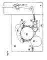
- FIG. 3schematically shows an inventive arrangement of the cleaning point in a cleaner shaft.
- the feed roller 9 and feed trough 10together transport the cotton flakes from the upper part of the hopper (7) on the opening roller (1), also known as opener roller.
- the smallest distance between the feed trough and the feed rollforms the feeding point or clamping point.
- This pointis called transfer point (17) - but is also known as Kämmstelle or Kämmddling.
- the cotton fibersare transferred here to the opening roller.
- This outlet channelmay, for example, be in the form of an evacuated channel, or in the form of a channel directed directly downwards, whereby gravity helps with removal.
- the fiber flakes adhering to the clothing of the opening rollerare guided past a knife edge (3) directly after the meshing point, at which further coarse dirt and unresolved fiber knots are eliminated.
- the distance of the knife edge from the transfer pointis adjustable, whereby the amount of the outgoing quantity and thus also the cleaning efficiency can be influenced.
- the good fibersare further transported to the opening roller along a guide element, which is directly downstream of the knife.
- the fiber materialis then dropped tangentially from the opening roller into the lower shaft part (8). There it can be further compressed by, via a compression fan, introduced air (13). Also, directing an air stream directly onto the opening roller to aid in the shedding of the floc and / or fibers may be an option. About a sieve wall at the back of the lower shaft (14), this air is discharged again.
- the outlet rollers 15 in the lower shaftthe cotton wool is presented on the inlet plate 16 of the feed roller of the card.
- FIG. 4shows a Wanderdeckelkarde 20, z.
- the Rieter card C60with a working width of 1.5 meters, with a cleaner shaft 6 according to the invention.
- Fiber flakesare transported through transport channels (not shown) through the various cleaning process steps and finally fed into the cleaner shaft of the card. This then passes the fiber flakes to the card as cotton wool.
- the feeder 27feeds the fiber flakes to the lickerins 21.
- the lickerinsopen the fiber flakes and remove some of the debris.
- the last licker-in rollertransfers the fibers to the card drum 22.
- the card drum 22cooperates with the lids 24 and further parallelizes the fibers.
- the lidsare cleaned by a lid cleaning 25. After the fibers have carried out several times several rounds on the card drum, they are removed from the doffer roller 23 of the card drum, fed to the squeegee 26 and finally stored as a card sliver in a can in a pot (not shown).
- FIG. 5is a guide element with knife edge shown. It can also be considered as an extended knife.
- the production of such a knifecan be done, for example, by manufacturing a straight knife plate with a knife edge in a first production step. In a second production step, you can then bend the extended knife across the width in the desired radius. Preferably such that the radius in Running direction of the opening roller is greater. As a result, the gap between the element and the roller opens, which causes the discharge of the fibers.
- the production stepscould also be reversed. But to achieve an accurate knife edge this is not advantageous.
- the knife edgecan be formed in particular by mechanical processing of the sheet in a straight shape, for example by milling or grinding.
- the knife edgeis ground only on one side, in particular the side averted from the roller.
- the side facing the rollerforms a smooth surface and prevents fiber adhesion.
- the extended blade according to the inventioncan also be formed from two parts.
- the extended knife fasteners (5)are arranged, for example, a slot and a fastening screw, preferably only on the front sides of the blade (In FIG. 5 drawn only on one side of the knife.)
- the means of Befest Trent.derartare arranged so that the distance between the transfer point and the knife edge is adjustable, which includes a shift in the radial direction. This setting can then preferably be changed manually or automatically, preferably by means of a drive.
- the cleaner shaftcould be equipped with an autonomous own control, or be connected to a higher-level control system, for example, the card or that of the entire system.
- the cleaning degree, the fiber load in the form of fiber damage and / or Nisse, nanmination and the Gutfaserfic in the departureare important parameters, which are partly related. For example, a high degree of cleaning goes on, also mostly coupled with an increased fiber load.
- These parameterscan be linked with machine parameters, such as the speed of the opening roller, the distance transfer point-knife edge, or the distance nip point transfer point. To simplify the setting, these settings can be integrated into a panel, such as in EP 452 676 has been described.
- Operationis simplified in such a way that the operator only has to take a few decisions and thus be able to set all the machine parameters, for example the group parameters, the cleaning intensity and the output quantity. It is also possible to measure combinations with parameters on the card, for example an adjustment of the settings on the basis of a measured parameter on the card, for example nits, dunes or thick places. These can be measured z. B. on the web in the acceptance area or on the tape.
Landscapes
- Engineering & Computer Science (AREA)
- Textile Engineering (AREA)
- Preliminary Treatment Of Fibers (AREA)
- Control Of Vending Devices And Auxiliary Devices For Vending Devices (AREA)
Description
Translated fromGermanDie vorliegende Erfindung bezieht sich auf einen Reinigerschacht für Spinnereimaschinen, zum Beispiel Karden, Krempel.The present invention relates to a cleaner shaft for spinning machines, for example carding, carding.
Die Materialzufuhr der Karde hat einen Einfluss auf dem Endprodukt der Karde: Das Kardenband. Unregelmässigkeiten in der Speisung sind in dem Band feststellbar, da sie für die Bildung von Dick- oder Dünnstellen zuständig sind, c. q. die Bildung von dick- oder Dünnstellen verursachen. Diese Fehlstellen können im Lauf der restlichen Prozesse, um ein Garn zu produzieren, kaum korrigiert werden und haben daher einen direkten Einfluss auf die endgültige Garnqualität. Um zu gleichmässigen Vorlagen zu kommen, muss die Watte, die in dem Speiseschacht geformt wird, über die Breite gleich verteilt und von gleicher Dichte sein. Ein Problem dabei ist die pneumatische Flockenzufuhr, die die einzelne Karde mit Flocken ungleichmässig anspeist. Dieses Problem wurde gelöst durch einen Schacht, der durch eine Speisevorrichtung in zwei Teilen geteilt wurde, wodurch die tatsächliche Wattevorlage zu der Karde nur noch lokal von dieser Speisevorrichtung beeinflusst wird.The material supply of the card has an influence on the end product of the card: the card sliver. Irregularities in the feed are detectable in the tape since they are responsible for the formation of thick or thin spots, c. q. cause the formation of thick or thin areas. These defects can hardly be corrected in the course of the remaining processes to produce a yarn and therefore have a direct influence on the final yarn quality. In order to obtain even patterns, the cotton wool formed in the feed chute must be evenly distributed across the width and of equal density. A problem with this is the pneumatic flocculation, which feeds the single card with flakes unevenly. This problem has been solved by a shaft which has been split by a feed device in two parts, whereby the actual cotton sheet to the card is only locally influenced by this feed device.
Eine weitere Forderung an die Vorlage, insbesondere für Hochleistungskarden, ist ein hoher Auflösegrad, da ein Teil der Leistungssteigerung dieser Karden gegenüber konventionellen Karden durch eine grössere Garniturbeaufschlagung zustande kommt und man dadurch entsprechend feiner geöffnetes Material benötigt. Daher wurde direkt nach der Speisevorrichtung eine Auflösewalze angeordnet, die die Flocken weitgehend auflöst. Obwohl die Schächte mittels einer Verbesserung des Lufthaushalts und konstruktiven Verbesserungen optimiert wurden, ist das Grundprinzip des zweiteiligen Schachtes geblieben und wird heute grundsätzlich eingesetzt.Another requirement for the template, especially for high-performance cards, is a high degree of resolution, since part of the increase in performance of these cards compared to conventional carding comes about by a larger Garniturbeaufschlagung and thus requires correspondingly finer open material. Therefore, an opening roller was placed directly after the feed device, which largely dissolves the flakes. Although the shafts have been optimized by means of improving the air quality and design improvements, the basic principle of the two-part shaft has remained and is in principle used today.
Die heutige Generation von Hochleistungskarden haben eine Produktion von bis zu 180 Kg pro Stunde. Bei diesen hohen Produktionen sind die Forderungen an die Vorlage gestiegen. Für die Vorreinigung dieser Vorlage sind im Putzereiprozess hauptsächlich die Reinigungsmaschinen, wie Grobreiniger oder Feinreiniger, zuständig.
Der Grobreiniger ist meistens am Anfang des Prozesses direkt nach dem Ballenöffner, die die Baumwolle von den Ballen abträgt und in den pneumatischen Transport einspeist, angeordnet. Den Grobreiniger gibt es in sehr verschiedenen Modellen, allerdings haben sie einige gemeinsame Merkmale. Das Material wird meistens im freien Flug unter Benutzung von grobbestückten Arbeitswalzen bearbeitet. Die Öffnungswirkung ist daher gering und vor allem grober Schmutz, der an der Aussenseite der Flocken vorhanden ist, wird entfernt. Grobreiniger entfernen zusätzlich freie Schmutzpartikel, wie Schalenteile oder andere Fremdkörper.Today's generation of high performance canards have a production of up to 180 kg per hour. With these high productions, the demands on the original have increased. For the pre-cleaning of this template are in the cleaning process mainly the cleaning machines, such as coarse cleaner or fine cleaner, responsible.
The coarse cleaner is usually at the beginning of the process directly after the bale opener, which removes the cotton from the bales and fed into the pneumatic transport arranged. The coarse cleaner is available in very different models, but they have some common features. The material is usually processed in free flight using coarsely stocked work rolls. The opening effect is therefore low and above all coarse dirt, which is present on the outside of the flakes is removed. Coarse cleaners also remove free dirt particles, such as shell parts or other foreign bodies.
Der Feinreiniger kommt viel später im Verfahren und ist meistens unmittelbar den Karden vorgeordnet. Der Feinreiniger ist mehr auf die Entfernung von Schmutz aus dem Inneren der Flocken gerichtet. Daher soll dieser Reinigungsschritt nach einem zusätzlichen Öffnungsschritt stattfinden. Der Feinreiniger arbeitet fast immer mit geklemmter Speisung und einer feineren Bestückung der der Speisung nachgeordneten Walze. Für eine intensivere Reinigung wird die Auflösewalze als Reinigungswalze ausgestattet, zum Beispiel mit Rostmessem und eine Sägezahngarnitur auf der Walze.The fine cleaner comes much later in the process and is usually directly upstream of the card. The fine cleaner is more focused on the removal of dirt from inside the flakes. Therefore, this cleaning step should take place after an additional opening step. The fine cleaner almost always works with clamped feed and a finer placement of the feed downstream roller. For more intensive cleaning, the opening roller is equipped as a cleaning roller, for example with grating knives and a saw tooth set on the roller.
Reinigerschächte, eine Füllschacht mit einer Reinigerfunktion, sind in der Praxis noch keine vorhanden.
Die offenbarten Anordnungen haben hauptsächlich den Nachteil, dass sie aufwendig in der Konstruktion und dadurch teuer werden. Zusätzlich würden sie aus technologische Gesichtpunkt nicht zuverlässig Funktionieren können. Die Erfindung liegt demgegenüber die Aufgabe zugrunde, eine Vorrichtung der eingangs beschriebenen Art zu schaffen, die die genannten Nachteile vermeidet, die insbesondere die Feinreinigungsfunktion in den Füllschacht integriert, ohne die aufwendige Konstruktion der Feinreiniger zu übernehmen.The disclosed arrangements have mainly the disadvantage that they become expensive in construction and therefore expensive. Additionally, they would not be able to function reliably from a technological point of view. The invention is based on the object, a device of the above to create the type described, which avoids the disadvantages mentioned, which in particular integrates the fine cleaning function in the hopper, without taking over the complex construction of the fine cleaner.
Die Lösung dieser Aufgabe erfolgt durch die kennzeichnenden Merkmale des Anspruchs 1. Durch das Messer, direkt der Übergabestelle nachzuordnen, werden nicht nur die Schmutzteilchen, die durch die Zentrifugalkraft der Auflösewalze nach aussen geschleudert werden, entfernt, sondern auch die Teilchen, die durch die "kämmende Wirkung" der Übergabestelle freigesetzt werden. Ein Leitelement, angeordnet vor dem Messer direkt nach der Übergabestelle, würden diese freigesetzten Teilchen auf die Walze zurückdrücken und dadurch die Entfernung benachteiligen. Direkt bedeutet hier dann auch ohne dazwischen angeordnete Elemente, die eine Einfluss auf die Ausscheidebewegung der Schmutzpartikel ausüben könnten.The solution of this object is achieved by the characterizing features of
Der Abwurf von Teilchen auf einer Walze, wie z.B. Schmutzpartikel oder Fasern, wird bewirkt durch die Zentrifugalkraft erzeugt durch die Auflösewalze (2), die tangential zur Walzeoberfläche (1) in Drehrichtung verläuft (siehe schematische Darstellung in
Allerdings ist es unerwünscht, dass sowohl der Schmutz als auch die Fasern auf dem gleichen Punkt abgeworfen werden. Daher braucht es zwei Abwerfstellen: die Schmutzabwerfstelle und die Faserabwerfstelle. Obwohl in einem Idealfall für ein Teilchen einen genauen Abwurfpunkt festgelegt werden kann, handelt es in der Praxis nicht um einen genauen Punkt, sondern bei Schmutz oder Fasern um ein Abwurfgebiet.However, it is undesirable for both the dirt and the fibers to be dropped at the same point. Therefore, there are two drop points: the dirt dump and the fiber drop point. Although in an ideal case for a In practice, particles can not be pinpointed, but dirt or fibers around a drop zone.
Um eine konstante Reinigung im Reinigungsschacht gemäss Erfindung zu erzielen, sind die beide Abwurfstelle vorzugsweise derart angeordnet, dass eine störungsfreie Abgangentsorgung gewährleistet wird, und eventuelle Beeinträchtigungen des Lufthaushaltes ausgeschlossen werden.In order to achieve a constant cleaning in the cleaning shaft according to the invention, the two discharge point are preferably arranged so that a trouble-free disposal of waste is ensured, and any adverse effects on the air balance are excluded.
Die Schmutzabwurfstelle, nachher Ausscheidungsstelle genannt, wird definiert durch den Ausscheid-Spalt zwischen der Übergabestelle und der Messerkante. Wobei die Übergabestelle definiert wird als der Punkt, wo die kleinste Distanz zwischen der Garnitur der Speisevorrichtung und die der Auflösewalze ist. Diese Stelle wird auch manchmal Kämmpunkt genannt, hier werden die Fasern von der Auflösewalze übernommen. Die Distanz zwischen der Übergabestelle und der Messerkante ausgedrückt in den Winkel (β) zwischen der Übergabestelle und der Messerkante, gemessen von der Übergabestelle durch die Drehachse der Öffnerwalze in Drehrichtung, ist zwischen 10° und 65°, vorzugsweise zwischen 10° und 45°, insbesondere zwischen 20° und 32°. Diese Distanz beeinflusst die Öffnung der Ausscheid-Spalt und dadurch die Abgangsmenge und Abgangszusammenstellung.The dirt discharge point, called after the precipitation point, is defined by the separation gap between the transfer point and the knife edge. Wherein the transfer point is defined as the point where the smallest distance between the clothing of the feed device and that of the opening roller is. This point is sometimes called Kämmpunkt, here the fibers are taken over by the opening roller. The distance between the transfer point and the knife edge expressed in the angle (β) between the transfer point and the knife edge, measured from the transfer point through the axis of rotation of the opening roller in the direction of rotation, is between 10 ° and 65 °, preferably between 10 ° and 45 °, in particular between 20 ° and 32 °. This distance affects the opening of the separation gap and thereby the leaving amount and leaving composition.
Da der Reinigerschacht in erster Instanz gedacht ist für die Reinigung von Baumwolle, ist die Einstellung der Winkel (β) abhängig von unter anderem der Länge der einzelnen Fasern und dem Grad der Verschmutzung. Der Füllschacht kann aber auch durch das Messer auf einen minimalen Stand zu stellen, für die Auflösung von Chemiefasern benutzt werden. Das Messer wird dann als ein normales Leitelement" funktionieren. Oder das Messer kann durch ein Leitblech ersetzt werden und die Reinigerschacht würde wie eine normale Füllschacht arbeiten können.
Durch die Auflösung bereits freigelegte Schmutzteile werden nach dem Übergabepunkt aus dem Schlagkreis gemäss der auf sie wirkender Zentrifugalkraft in den Abgangkanal herausgeschleudert. Deswegen ist vorzugsweise die Speisewalze gegenüber der Auflösewalze in einen Winkel (α) von 25° bis 90° geneigt (gemessen durch die Drehachse der Speisewalze und der Auflösewalze gegenüber der Vertikalebene durch die Drehachse der Auflösewalze in Drehrichtung der Auflösewalze.) .Since the cleaner shaft is intended in the first instance for the cleaning of cotton, the adjustment of the angle (β) depends on inter alia the length of the individual fibers and the degree of contamination. The hopper can also be set by the knife to a minimum level, are used for the dissolution of chemical fibers. The knife will then function as a normal guide "or the knife may be replaced by a baffle and the cleaner well would be able to operate like a normal feed well.
By the resolution already exposed dirt particles are ejected to the transfer point from the beating circle according to the centrifugal force acting on them in the outlet channel. Therefore, preferably, the feed roller relative to the opening roller at an angle (α) of 25 ° to 90 ° inclined (measured through the axis of rotation of the feed roller and the opening roller relative to the vertical plane through the axis of rotation of the opening roller in the direction of rotation of the opening roller.).
Die Faserabwurfstelle soll vorzugsweise derart angeordnet werden, dass einen technologisch sinnvollen Abwurf der Gutfasern erfolgt. Da die Auflösung der Faserflocken an der Übergabestelle stattfindet, ist eine lange Verweilzeit der Fasern auf die Auflösewalze nicht technologisch sinnvoll, daher wirkt einen schnellen Abwurf speditiv auf den gesamten Prozess. Zwischen der Messerkante und der Abwurfstelle ist eine Leitfläche angeordnet, die eine klare Trennung zwischen der Ausscheidungsstelle und der Faserabwurfstelle ermöglicht. Diese Leitfläche kann als separates Leitelement oder zusammen mit dem Messer gebildet werden. Vorzugsweise wird das Messer nach hinten verlängert, wie später näher erklärt wird.The fiber discharge point should preferably be arranged in such a way that a technologically sensible discharge of the good fibers takes place. Since the dissolution of the fiber flakes takes place at the transfer point, a long residence time of the fibers on the opening roller does not make any sense in terms of technology, so a fast discharge is effective for the entire process. Between the knife edge and the discharge point a guide surface is arranged, which allows a clear separation between the precipitation point and the fiber discharge point. This guide surface can be formed as a separate guide element or together with the knife. Preferably, the knife is extended to the rear, as will be explained later.
Die Leitfläche kann parallel zu dem Radius der Walzeoberfläche verlaufen, wobei der Abstand zur Walzenoberfläche gleich bleiben kann oder sich öffnet. Sich öffnen heisst, dass der Abstand der beiden Flächen zueinander sich in Drehrichtung vergrössert. Sobald sich der Abstand öffnet, sind die Fasern geneigt sich nach aussen auf der Garnitur zu bewegen, damit sie abgeworfen werden können. Diese Bewegung der Fasern ist derart, dass die Abwurfstelle vorzugsweise in einen Winkel (γ) von 40° bis 55° (gemessen von der Anfang der Öffnung durch die Achse der Auflösewalze in Drehrichtung) angeordnet ist. Mit Anfang der Öffnung ist die Stelle gemeint, wo der Abstand von dem Leitelement gegenüber der Walzeoberfläche sich beginnt zu vergrössern. Vorzugsweise findet diese Öffnung direkt nach der Messerkante statt, die Abwurfstelle ist dann in einen Winkel (γ) von 40° bis 55°, gemessen von der Messerkante durch die Achse der Auflösewalze in Drehrichtung angeordnet.The guide surface can run parallel to the radius of the roller surface, wherein the distance to the roller surface can remain the same or opens. To open means that the distance between the two surfaces increases in the direction of rotation. Once the gap opens, the fibers are inclined to move outward on the clothing so that they can be thrown off. This movement of the fibers is such that the discharge point is preferably arranged at an angle (γ) of 40 ° to 55 ° (measured from the beginning of the opening through the axis of the opening roller in the direction of rotation). By the beginning of the opening is meant the point where the distance from the guide element to the roller surface begins to increase. Preferably, this opening takes place directly after the knife edge, the discharge point is then arranged in an angle (γ) of 40 ° to 55 °, measured from the knife edge through the axis of the opening roller in the direction of rotation.
Das Messer wird vorzugsweise mit dem Leitelement, das nachgeordnet ist, zusammengelegt. Die Messerkante wird durch das Schmutzpartikel und die Fasern, die über den Kanten streichen ein hohes Potenzial an Verschleiss haben. Dafür kann man entweder ein Verschleissfestes Material wählen und/ oder die Messerkante austauschbar machen.The knife is preferably combined with the guide element, which is arranged downstream. The edge of the knife will have a high potential for wear due to the dirt particles and the fibers that strike over the edges. You can either choose a wear-resistant material and / or make the knife edge interchangeable.
Eine alternative Lösung ist die Anfertigung von dem Messer und Leitelement aus einem Stück. Hiervor wird erst ein Stück Blech in die gewünschte Dicke angefertigt, die Messerkante geschliffen und dann das Blech in die gewünschte Krümmung gebogen. Hierdurch entsteht eine feinere. Messerkante, die keine zusätzlichen Befestigungen oder Rillen aufweist, wo Schmutz oder Faserfetzen anhangen können. Diese Fertigungstechnik hat als Vorteil, dass ein stabiles, kostengünstiges Messer gefertigt werden kann, das austauschbar ist. Vorzugsweise werden daher an die Seite dieses Messer die Befestigungselemente angeordnet, insbesondere Befestigungselementen, die eine Änderung der Einstellung der Distanz übergabestelle/Messerkante, während das Messer eingebaut ist, zulassen.An alternative solution is the production of the knife and guide element in one piece. Before this, a piece of sheet metal is first made into the desired thickness, the knife edge is ground and then the sheet is bent into the desired curvature. This creates a finer. Knife edge, which has no additional fasteners or grooves where dirt or fiber rags can stick. This production technique has the advantage that a stable, inexpensive knife can be manufactured, which is interchangeable. Preferably, therefore, the fastening elements are arranged on the side of this knife, in particular fasteners that allow a change in the setting of the distance transfer point / knife edge, while the knife is installed.
Beeinflusst wird der Reinigungsgrad die erzielt werden kann durch der Reinigerschacht nach der Erfindung vom Abstand der Messerkante zu den Nadelspitzen und vom Abstand der Messerkante zur Übergabestelle. Diese letzte Messereinstellung kann manuell verstellt werden oder mit Hilfe von einem Antrieb.
Dabei kann die Einstellung mit vorgegebenen Abständen oder stufenlos stattfinden. Zusätzlich kann die Einstellung kombiniert werden mit einer Steuerung, welche die Einstellung vornimmt oder anpasst, vorzugsweise in Abhängigkeit vom Verschmutzungsgrad, Faserlänge oder Provenienz. Diese Einstellung kann auch in Abhängigkeit sein von Parameter, die sonst auf der Karde gemessen werden, zum Beispiel die Nissenzahl im ausgehendem Produkt. Neben der Einstellung des Messers hat auch die Geschwindigkeit der Auflösewalze ein Effekt auf den Reinigungsgrad. Dieses Parameter kann mit in den Steuerung integriert werden.The degree of cleaning, which can be achieved by the cleaner shaft according to the invention, is influenced by the distance between the knife edge and the needle tips and by the distance between the knife edge and the transfer point. This last knife adjustment can be adjusted manually or with the help of a drive.
The adjustment can take place with predetermined intervals or steplessly. In addition, the adjustment can be combined with a controller that makes or adjusts the setting, preferably depending on the degree of soiling, fiber length or provenance. This setting can also be dependent on parameters that are otherwise measured on the card, for example the number of nits in the outgoing product. In addition to the setting of the knife and the speed of the opening roller has an effect on the degree of cleaning. This parameter can be integrated with the controller.
Beispielen und vorteilhafte Weiterbildungen der Erfindung werden anhand der Figuren erklärt. Die Referenznummern sind in alle Figuren gleich gehalten worden.
Figur 1- Schematische Darstellung der Kräfteverhältnisse, die auf den Teilchen ausgeübt werden (siehe Beschreibung oben).
Figur 2- Schema der erfindungsgemässen Anordnung der Reinigungsstelle
Figur 3- Schematisch Beispiel der erfinderischen Anordnung der Reinigerschacht.
Figur 4- Schematische Seitenansicht einer Karde mit dem Reinigerschacht gemäss Erfindung
Figur 5- Schematische Darstellung des Messers
- FIG. 1
- Schematic representation of the balance of forces exerted on the particles (see description above).
- FIG. 2
- Scheme of the inventive arrangement of the cleaning station
- FIG. 3
- Schematic example of the inventive arrangement of the cleaner shaft.
- FIG. 4
- Schematic side view of a card with the cleaner shaft according to the invention
- FIG. 5
- Schematic representation of the knife
- 1. α, die Winkel der Neigung der Speisewalze gegenüber die Auflösewalze gemessen durch die Drehachse der Speisewalze und der Auflösewalze gegenüber der Vertikalebene durch die Drehachse der Auflösewalze in Drehrichtung der Auflösewalze; .
- 2. β, die Winkel zwischen der Übergabestelle und der Messerkante gemessen von der Übergabestelle durch die Drehachse der Öffnerwalze in Drehrichtung und
- 3. γ, der Winkel zwischen der Messerkante oder der Anfang der Öffnung des Leitelements und der Abwurfstelle darstellt, wobei der Anfang der Öffnung des Leitelements die Stelle ist, ab wo die Distanz Leitelement - Walzeoberfläche sich beginnt zu vergrössern in Drehrichtung.
- 1. α, the angle of inclination of the feed roller against the opening roller measured by the axis of rotation of the feed roller and the opening roller relative to the vertical plane through the axis of rotation of the opening roller in the direction of rotation of the opening roller; ,
- 2. β, the angle between the transfer point and the knife edge measured from the transfer point by the axis of rotation of the opening roller in the direction of rotation and
- 3. γ, represents the angle between the knife edge or the beginning of the opening of the guide element and the discharge point, wherein the beginning of the opening of the guide element is the point from where the distance guide element - roller surface begins to increase in the direction of rotation.
Die Winkel α, β und γ zusammen übersteigen vorzugsweise die 180 - 200° nicht, damit die Faser-, Abwurfstelle auch noch an einer technologisch sinnvollen Stelle angeordnet ist. Es ist nicht notwendig die Speisewalze gegenüber der Auflösewalze in Drehrichtung zu neigen, allerdings wirkt schon eine geringe Neigung vorteilhaft auf die Schmutzentfernung aus. Ein Beispiel einer Reinigerschachtanordnung könnte daher sein ein α von 45°, ein β einstellbar zwischen 20° und 35° und γ von 45°. Die Schmutzausscheidestelle würde dann zwischen Winkel α und β, oder zwischen 45° und 80° liegen und die Auswurfstelle würde dann nach einem Gesamtwinkel von α, β und γ von maximal 125° liegen. Wobei nochmals bemerkt werden soll, dass es sich hier nicht um absolute Abwurfpunkte handelt, sondern um Bereiche. Bei diesem Beispiel der Reinigeranordnung sind die Schmutzausscheidestelle und die Faserabwurfstelle rundum des jeweiligen optimalen Abwurfpunkts angeordnet. Sowohl die Schmutzausscheidestelle als auch die Faserabwurfstelle haben noch dem Vorteil dass die Schwerkraft dem Abwurf der Teilchen unterstutzt und brauchen unter Umstände keine zusätzliche Absaugung für die Entfernung der abgeworfenen Teilchen.The angles α, β and γ together preferably do not exceed the 180-200 °, so that the fiber, discharge point is also arranged at a technologically meaningful point. It is not necessary to tilt the feed roller in the direction of rotation with respect to the opening roller, but even a slight inclination has an advantageous effect on the removal of dirt. An example of a cleaner shaft arrangement could therefore be an α of 45 °, a β adjustable between 20 ° and 35 ° and γ of 45 °. The soil removal point would then be between angles α and β, or between 45 ° and 80 °, and the ejection point would then lie at a total angle of α, β and γ of at most 125 °. Again, it should be noted that these are not absolute drop points, but areas. In this example of the cleaner arrangement, the soil discharge point and the fiber discharge point are arranged around the respective optimum discharge point. Both the Schmutzausscheidestelle and the Faserabwurfstelle have the advantage that gravity supports the dropping of the particles and need below Circumstances no additional suction for the removal of the discarded particles.
Es kann vorteilhaft sein ein zusätzliches Leitelement oder Prallblech (28) derart anzuordnen, dass die abgeworfenen Faerflocken in dem untersten Schachtteil umgelenkt werden. Vor allem, wenn die Gesamtwinkel in der Nähe von 180° bis 200° kommt.It may be advantageous to arrange an additional guide element or baffle plate (28) such that the discarded flakes are deflected in the lowermost part of the shaft. Especially if the total angle comes in the vicinity of 180 ° to 200 °.
Die Flocken werden weitertransportiert zwischen den beiden Walzen bis sie die kleinste Distanz zwischen den beiden Walzen erreichen. Dieser Punkt wird Übergabestelle (17) genannt - ist aber auch als Kämmstelle oder Kämmpunkt bekannt. Die Baumwollfasern werden hier der Auflösewalze übergeben. Durch die Auflösung bereits freigelegte Schmutzteilchen werden nach der Übergabestelle aus dem Schlagkreis gemäss der auf sie wirkenden Zentrifugalkraft in den Abgangkanal (12) herausgeschleudert. Dieser Abgangkanal kann zum Beispiel in Form eines abgesaugten Kanals sein, oder in Form eines Kanals, der direkt nach unten gerichtet ist, wodurch die Schwerkraft hilft mit dem Abtransport.The flakes are transported further between the two rolls until they reach the smallest distance between the two rolls. This point is called transfer point (17) - but is also known as Kämmstelle or Kämmpunkt. The cotton fibers are transferred here to the opening roller. By the resolution already exposed dirt particles are ejected to the transfer point from the beating circle according to the centrifugal force acting on them in the outlet channel (12). This outlet channel may, for example, be in the form of an evacuated channel, or in the form of a channel directed directly downwards, whereby gravity helps with removal.
Die auf der Garnitur der Auflösewalze haftenden Faserflocken werden direkt nach dem Kämmpunkt an einer Messerkante (3) vorbeigeführt, an der weiterer Grobschmutz und nicht aufgelöste Faserverknotungen ausgeschieden werden. Der Abstand der Messerkante von der Übergabestelle ist einstellbar, wodurch die Höhe der Abgangmenge und damit auch die Reinigungseffizienz beeinflusst werden können.The fiber flakes adhering to the clothing of the opening roller are guided past a knife edge (3) directly after the meshing point, at which further coarse dirt and unresolved fiber knots are eliminated. The distance of the knife edge from the transfer point is adjustable, whereby the amount of the outgoing quantity and thus also the cleaning efficiency can be influenced.
Die Gutfasern werden weiter auf die Auflösewalze transportiert, einem Leitelement entlang, das dem Messer direkt nachgeordnet ist. Das Fasermaterial wird dann tangential von der Auflösewalze in den unteren Schachtteil (8) abgeworfen. Dort kann es durch, über einen Verdichtungsventilator, eingebrachte Luft (13) weiter verdichtet werden. Auch ein Luftstrom direkt auf der Auflösewalze gerichtet um das Abwerfen der Flocken und oder Fasern zu unterstützen, kann eine Option sein. Über eine Siebwand an der Rückseite des Unterschachtes (14) wird diese Luft wieder abgeführt. Durch die Auslaufwalzen 15 im Unterschacht wird die Watte auf dem Einlaufblech 16 der Speisewalze der Karde vorgelegt.The good fibers are further transported to the opening roller along a guide element, which is directly downstream of the knife. The fiber material is then dropped tangentially from the opening roller into the lower shaft part (8). There it can be further compressed by, via a compression fan, introduced air (13). Also, directing an air stream directly onto the opening roller to aid in the shedding of the floc and / or fibers may be an option. About a sieve wall at the back of the lower shaft (14), this air is discharged again. Through the
In
Die Produktion so ein Messer kann zum Beispiel erfolgen durch in einen ersten Produktionsschritt ein gerades Messerblech mit Messerkante zu fertigen. In einem zweiten Produktionsschritt kann man dann das verlängerte Messer über die Breite in den gewünschten Radius biegen. Vorzugsweise derart, dass der Radius in Laufrichtung der Auflösewalze grösser wird. Dadurch öffnet sich der Spalt zwischen das Element und der Walze, was der Abwurf der Fasern bewirkt.
Die Produktionsschritte könnten auch umgekehrt stattfinden. Aber um eine genaue Messerkante zu erreichen ist dieses nicht vorteilhaft.The production of such a knife can be done, for example, by manufacturing a straight knife plate with a knife edge in a first production step. In a second production step, you can then bend the extended knife across the width in the desired radius. Preferably such that the radius in Running direction of the opening roller is greater. As a result, the gap between the element and the roller opens, which causes the discharge of the fibers.
The production steps could also be reversed. But to achieve an accurate knife edge this is not advantageous.
Die Messerkante kann insbesondere durch mechanische Bearbeitung des Blechs in Gerade Form geformt werden, zum Beispiel durch fräsen oder schleifen. Vorzugsweise ist die Messerkante nur einseitig geschliffen, insbesondere die Seite abgewendet von der Walze. Dadurch formt die Seite, die der Walze zugekehrt ist, eine glatte Oberfläche und verhindert Faserhaftung. Alternativ kann das verlängerte Messer gemäss Erfindung auch aus zwei Teilen gebildet werden.The knife edge can be formed in particular by mechanical processing of the sheet in a straight shape, for example by milling or grinding. Preferably, the knife edge is ground only on one side, in particular the side averted from the roller. As a result, the side facing the roller forms a smooth surface and prevents fiber adhesion. Alternatively, the extended blade according to the invention can also be formed from two parts.
Um das verlängerte Messer zu befestigen sind Befestigungselementen (5) angeordnet, zum Beispiel eine Schlitz und eine Befestigungsschraube, vorzugsweise nur an den Stirnseiten des Messers (In
Der Reinigerschacht könnte mit einer autonomen eigener Steuerung ausgestattet werden, oder an ein übergeordnetes Steuersystem zum Beispiel die der Karde oder die der Gesamtanlage angeschlossen werden. Für ein gutes Funktionieren des Reinigerschachtes sind die Reinigungsgrad, die Faserbelastung im Form von Faserschädigung und /oder Nisse,nanstieg und der Gutfaserverlust im Abgang, wichtige Parameter, die teilweise miteinander zusammenhängen. Zum Beispiel geht eine hohe Reinigungsgrad, auch meistens gepaart mit einer erhöhten Faserbelastung. Diese Parameter können verbunden werden mit Maschineparameter, wie die Geschwindigkeit der Auflösewalze, die Distanz Übergabestelle-Messerkante, oder die Distanz Klemmpunkt-Übergabepunkt. Um die Einstellung zu vereinfachen können diese Einstellungen in ein Bedienerfeld integriert werden, wie zum Beispiel in
Auch Kombinationen mit Parameter an der Karde gemessen sind möglich zum Beispiel eine Verstellung der Einstellungen anhand von einem gemessenen Parameter an der Karde zum Beispiel Nissen, Dunn- oder Dickstelle. Diese können gemessen worden z. B. am Vlies im Abnahmebereich oder am Band.The cleaner shaft could be equipped with an autonomous own control, or be connected to a higher-level control system, for example, the card or that of the entire system. For a good functioning of the cleaner shaft, the cleaning degree, the fiber load in the form of fiber damage and / or Nisse, nanstieg and the Gutfaserverlust in the departure, are important parameters, which are partly related. For example, a high degree of cleaning goes on, also mostly coupled with an increased fiber load. These parameters can be linked with machine parameters, such as the speed of the opening roller, the distance transfer point-knife edge, or the distance nip point transfer point. To simplify the setting, these settings can be integrated into a panel, such as in
It is also possible to measure combinations with parameters on the card, for example an adjustment of the settings on the basis of a measured parameter on the card, for example nits, dunes or thick places. These can be measured z. B. on the web in the acceptance area or on the tape.
- 1. Auflösewalze (auch bekannt als Öffnerwalze1. opening roller (also known as opener roller
- 2. Walzeoberfläche2nd roller surface
- 3. Messerkante3. knife edge
- 4. Leitelement4th guide element
- 5. Befestigungselement5. Fastening element
- 6. Reinigerschacht6. Cleaner shaft
- 7. Oberen Schachtteil7. Upper shaft part
- 8. Unteren Schachtteil8. Lower shaft part
- 9. Speisewalze9. Feed roller
- 10. Speisemulde10. Food trough
- 11. Garnitur11. clothing
- 12. Schmutzausscheidungskanal (auch Abgangskanal)12. dirt discharge channel (also leaving channel)
- 13. Einblasluftzufuhr untere Schachtteil13. Einblasluftzufuhr lower shaft part
- 14. Durchlässige Wand für die Abtrennung von Luft und Staub14. Permeable wall for the separation of air and dust
- 15. Speisevorrichtung15. Feed device
- 16. Leitblech16. baffle
- 17. Übergabestelle (auch Kämmstelle)17th transfer point (also Kämmstelle)
- 18.Schmuzausscheidestelle (auch Schmutzabwurfstelle)18. Schmuzausscheidestelle (also dirt dump)
- 19. Faserabwurfstelle19th fiber discharge point
- 20. Karde20th card
- 21.Vorreiser (auch bekannt als Briseur)21. Preliminary Traveler (also known as Briseur)
- 22. Trommel oder Tambour22. Drum or drum
- 23. Abnahmewalze23. Pick-up roller
- 24.Wanderdeckelsatz24.Wanderdeckelsatz
- 25. Reinigungselementen für die Wanderdeckel25. Cleaning elements for the revolving lids
- 26. Auslauf26. Spout
- 27. Speisevorrichtung27. Feed device
- 28. Prallblech oder Leitelement28. baffle plate or guide element
- α Neigungswinkel von der Speisewalze gegenüber der Auflösewalzeα angle of inclination of the feed roller against the opening roller
- β Winkel zwischen Übergabestelle und Messerkanteβ angle between transfer point and knife edge
- γ Winkel zwischen Messerkante und Faserabwurfstelleγ Angle between knife edge and fiber discharge point
Claims (18)
- A cleaner shaft (6) for a spinning machine, with a roller (1), preferably an opening roller, and with a knife arranged on this roller and having a knife edge (3) arranged opposite to the direction of rotation of the roller, and with a feed device for the roller, preferably a feed roller (9) having a trough (10), the feed device being assigned to the roller in such a way as to form a transfer point (17),characterized in that the knife is arranged directly downstream of the transfer point.
- The cleaner shaft as claimed in claim 1,characterized in that the transfer point (17) is formed where the plane through the axes of rotation of the drawer-in and opening roller is inclined at an angle (α) of 25° to 90° with respect to the vertical plane through the axis of rotation of the opener roller in the direction of rotation of the opener roller.
- The cleaner shaft as claimed in claim 1 or 2,characterized in that the angle (β) between the transfer point and the knife edge is between 10° and 65°, in particular between 10° and 45°, measured from the transfer point through the axis of rotation of the opener roller in the direction of rotation.
- The cleaner shaft as claimed in one of the preceding claims,characterized in that the angle (γ) between the knife edge and the start of the fiber throw-off point is between 40° and 55°, measured from the knife edge through the axis of rotation of the opener roller in the direction of rotation.
- The cleaner shaft as claimed in one of the preceding claims,characterized in that a guide element (4) follows the knife edge.
- The cleaner shaft as claimed in claim 5,characterized in that the knife edge and the guide element are in one piece.
- The cleaner shaft as claimed in claim 5 or 6,characterized in that the distance of the guide element from the surface of the clothing on the roller is constant.
- The cleaner shaft as claimed in claim 5, 6 or 7,characterized in that the distance of the guide element from the surface of the clothing on the roller remains the same.
- The cleaner shaft as claimed in claim 5, 6 or 7,characterized in that the distance of the guide element from the surface of the clothing on the roller increases in the direction of rotation.
- The cleaner shaft as claimed in claim 9,characterized in that this increase in the distance starts directly downstream of the knife edge.
- The cleaner shaft as claimed in claim 9,characterized in that this increase in the distance starts downstream of a region having a constant distance of the guide element from the roller surface.
- The cleaner shaft as claimed in claim 11,characterized in that the angle (γ) between the start of the increase in the distance and the start of the fiber throw-off point is between 40° and 55°, measured from the start of the increase in the distance through the axis of rotation of the opener roller in the direction of rotation.
- The cleaner shaft as claimed in one of claims 1 to 12,characterized in that the setting of the knife edge with respect to the transfer point can be set.
- The cleaner shaft as claimed in claim 13,characterized in that mechanical means, for example a drive, are provided for the setting.
- The cleaner shaft as claimed in one of claims 1 to 14,characterized in that this may be connected to a control or itself contains a control.
- A knife for the cleaner shaft as claimed in one of claims 1 to 15,characterized in that it is formed, together with the guide element, from a metal sheet.
- The knife as claimed in claim 16,characterized in that the knife edge contains on only one side a ground knife portion which is arranged on the side facing away from the opening roller.
- The knife as claimed in claim 16 or 17,characterized in that the knife, together with the guide element, has a curved radius such that the guide element can be arranged parallel to the surface of the opening roller.
Applications Claiming Priority (2)
| Application Number | Priority Date | Filing Date | Title |
|---|---|---|---|
| CH4622004 | 2004-03-18 | ||
| PCT/CH2005/000161WO2005087994A1 (en) | 2004-03-18 | 2005-03-17 | Cleaning shaft |
Publications (2)
| Publication Number | Publication Date |
|---|---|
| EP1733080A1 EP1733080A1 (en) | 2006-12-20 |
| EP1733080B1true EP1733080B1 (en) | 2008-05-21 |
Family
ID=34961749
Family Applications (1)
| Application Number | Title | Priority Date | Filing Date |
|---|---|---|---|
| EP05714703AExpired - LifetimeEP1733080B1 (en) | 2004-03-18 | 2005-03-17 | Cleaning shaft |
Country Status (5)
| Country | Link |
|---|---|
| EP (1) | EP1733080B1 (en) |
| CN (1) | CN1954104A (en) |
| BR (1) | BRPI0508907A (en) |
| DE (1) | DE502005004191D1 (en) |
| WO (1) | WO2005087994A1 (en) |
Families Citing this family (27)
| Publication number | Priority date | Publication date | Assignee | Title |
|---|---|---|---|---|
| US7630006B2 (en) | 1997-10-09 | 2009-12-08 | Fotonation Ireland Limited | Detecting red eye filter and apparatus using meta-data |
| US7738015B2 (en) | 1997-10-09 | 2010-06-15 | Fotonation Vision Limited | Red-eye filter method and apparatus |
| US7574016B2 (en) | 2003-06-26 | 2009-08-11 | Fotonation Vision Limited | Digital image processing using face detection information |
| US8254674B2 (en) | 2004-10-28 | 2012-08-28 | DigitalOptics Corporation Europe Limited | Analyzing partial face regions for red-eye detection in acquired digital images |
| US7920723B2 (en) | 2005-11-18 | 2011-04-05 | Tessera Technologies Ireland Limited | Two stage detection for photographic eye artifacts |
| US7689009B2 (en) | 2005-11-18 | 2010-03-30 | Fotonation Vision Ltd. | Two stage detection for photographic eye artifacts |
| US8170294B2 (en) | 2006-11-10 | 2012-05-01 | DigitalOptics Corporation Europe Limited | Method of detecting redeye in a digital image |
| US7970182B2 (en) | 2005-11-18 | 2011-06-28 | Tessera Technologies Ireland Limited | Two stage detection for photographic eye artifacts |
| US7587085B2 (en) | 2004-10-28 | 2009-09-08 | Fotonation Vision Limited | Method and apparatus for red-eye detection in an acquired digital image |
| US7792970B2 (en) | 2005-06-17 | 2010-09-07 | Fotonation Vision Limited | Method for establishing a paired connection between media devices |
| US8036458B2 (en) | 2007-11-08 | 2011-10-11 | DigitalOptics Corporation Europe Limited | Detecting redeye defects in digital images |
| US8520093B2 (en) | 2003-08-05 | 2013-08-27 | DigitalOptics Corporation Europe Limited | Face tracker and partial face tracker for red-eye filter method and apparatus |
| US9412007B2 (en) | 2003-08-05 | 2016-08-09 | Fotonation Limited | Partial face detector red-eye filter method and apparatus |
| US7599577B2 (en) | 2005-11-18 | 2009-10-06 | Fotonation Vision Limited | Method and apparatus of correcting hybrid flash artifacts in digital images |
| DE102006005391A1 (en) | 2006-02-03 | 2007-08-09 | TRüTZSCHLER GMBH & CO. KG | Device on a card, carding o. The like., For cleaning fiber material z. As cotton, with a high-speed or main roller |
| DE102006005389A1 (en) | 2006-02-03 | 2007-08-09 | TRüTZSCHLER GMBH & CO. KG | Device on a card, carding o. The like., For cleaning fiber material z. B. cotton, which has a high-speed first or main roll |
| DE102006005390B4 (en) | 2006-02-03 | 2021-08-12 | Trützschler GmbH & Co Kommanditgesellschaft | Device on a card, card or the like. For cleaning fiber material z. B. made of cotton, which comprises a high-speed first or main roller |
| EP1987475A4 (en) | 2006-02-14 | 2009-04-22 | Fotonation Vision Ltd | Automatic detection and correction of non-red eye flash defects |
| EP2033142B1 (en) | 2006-06-12 | 2011-01-26 | Tessera Technologies Ireland Limited | Advances in extending the aam techniques from grayscale to color images |
| US8055067B2 (en) | 2007-01-18 | 2011-11-08 | DigitalOptics Corporation Europe Limited | Color segmentation |
| JP2010520567A (en) | 2007-03-05 | 2010-06-10 | フォトネーション ビジョン リミテッド | Red-eye false detection filtering using face position and orientation |
| US8503818B2 (en) | 2007-09-25 | 2013-08-06 | DigitalOptics Corporation Europe Limited | Eye defect detection in international standards organization images |
| US8212864B2 (en) | 2008-01-30 | 2012-07-03 | DigitalOptics Corporation Europe Limited | Methods and apparatuses for using image acquisition data to detect and correct image defects |
| US8081254B2 (en) | 2008-08-14 | 2011-12-20 | DigitalOptics Corporation Europe Limited | In-camera based method of detecting defect eye with high accuracy |
| US8121543B2 (en) | 2008-12-26 | 2012-02-21 | Nokia Corporation | Power management |
| KR102154944B1 (en) | 2011-06-03 | 2020-09-11 | 알러간 인더스트리 에스에이에스 | Dermal filler compositions including antioxidants |
| CH719002A1 (en)* | 2021-09-28 | 2023-03-31 | Rieter Ag Maschf | Cleaning device for fiber material. |
Family Cites Families (5)
| Publication number | Priority date | Publication date | Assignee | Title |
|---|---|---|---|---|
| US2933770A (en)* | 1959-04-20 | 1960-04-26 | Community Gin Company | Rotary knife cotton gin |
| SU333851A1 (en)* | 1970-06-30 | 1974-01-05 | А. Г. Емин, Л. Н. Сафонова, Э. А. Копелевич, Ю. Ф. Чукаев, | PNEUMATIC REMOVER FIBER MATERIAL |
| DE8705138U1 (en)* | 1987-04-07 | 1988-08-04 | Hergeth Hollingsworth GmbH, 4408 Dülmen | Device for cleaning and opening textile fibres |
| DE59109076D1 (en)* | 1990-03-22 | 1999-01-28 | Rieter Ag Maschf | Cleaning map |
| EP0877104A1 (en)* | 1997-05-07 | 1998-11-11 | Jossi Holding AG | Apparatus for treating a fiber material stream in a fiber preparation plant |
- 2005
- 2005-03-17EPEP05714703Apatent/EP1733080B1/ennot_activeExpired - Lifetime
- 2005-03-17BRBRPI0508907-7Apatent/BRPI0508907A/ennot_activeIP Right Cessation
- 2005-03-17DEDE502005004191Tpatent/DE502005004191D1/ennot_activeExpired - Fee Related
- 2005-03-17CNCNA2005800158438Apatent/CN1954104A/enactivePending
- 2005-03-17WOPCT/CH2005/000161patent/WO2005087994A1/enactiveIP Right Grant
Also Published As
| Publication number | Publication date |
|---|---|
| BRPI0508907A (en) | 2007-08-07 |
| DE502005004191D1 (en) | 2008-07-03 |
| WO2005087994A1 (en) | 2005-09-22 |
| CN1954104A (en) | 2007-04-25 |
| EP1733080A1 (en) | 2006-12-20 |
Similar Documents
| Publication | Publication Date | Title |
|---|---|---|
| EP1733080B1 (en) | Cleaning shaft | |
| CH622033A5 (en) | ||
| EP1929075B1 (en) | Device for processing fibres at the drum of a card | |
| CH642117A5 (en) | DEVICE FOR OPENING AND CLEANING COTTON WASTE. | |
| CH626660A5 (en) | ||
| DE3429024C2 (en) | Method and device for separating dust from fiber material | |
| CH691598A5 (en) | Device in a spinning preparation device for detecting and separating foreign matter from fibrous material. | |
| DE4039773A1 (en) | DEVICE FOR OPENING AND CLEANING FIBER GOODS, IN PARTICULAR COTTON | |
| CH669610A5 (en) | ||
| EP1167590A2 (en) | Fibre length measuring | |
| CH695617A5 (en) | Device on a carder, covering elements are arranged in the underneath a drum between a buyer and a licker. | |
| EP0810309A1 (en) | Arrangement for the processing of fibres | |
| EP1929076B2 (en) | Apparatus for processing fibres on the drum of a carding machine | |
| DE10122459A1 (en) | Device on a card, cleaning machine, opening machine or the like for fiber material | |
| EP1338685B2 (en) | Method and device for cleaning the doffing area in a carding machine | |
| EP0419415B1 (en) | Method and apparatus for the fine cleaning of textile fibres | |
| DE2459781C2 (en) | Device for separating fiber cracks, fiber adhesions, foreign matter particles (strips) and short fibers when carding or carding fiber materials | |
| DE10051695A1 (en) | Device on a card for textile fibers such as cotton or the like | |
| DE19923418A1 (en) | Device for producing a fleece from fiber flakes, which has at least one substantially vertical shaft of rectangular cross-section | |
| CH695779A5 (en) | Cleaning device, in particular for a carding machine or cleaning machine for fibrous material, in particular cotton. | |
| CH691861A5 (en) | A device for cleaning fiber material at an open-end spinning aggregate. | |
| WO2019029914A1 (en) | TEASEL | |
| CH682672A5 (en) | A device for opening and cleaning fibers, especially cotton. | |
| DE3821771A1 (en) | Process for the separation of waste on a cotton card and cotton card | |
| DE10110825A1 (en) | Carding machine has suction openings in the drum cover under the drum for the extraction of detached fibers and debris from the drum clothing between the doffer and the licker-in |
Legal Events
| Date | Code | Title | Description |
|---|---|---|---|
| PUAI | Public reference made under article 153(3) epc to a published international application that has entered the european phase | Free format text:ORIGINAL CODE: 0009012 | |
| 17P | Request for examination filed | Effective date:20060905 | |
| AK | Designated contracting states | Kind code of ref document:A1 Designated state(s):CH DE IT LI TR | |
| DAX | Request for extension of the european patent (deleted) | ||
| RBV | Designated contracting states (corrected) | Designated state(s):CH DE IT LI TR | |
| GRAP | Despatch of communication of intention to grant a patent | Free format text:ORIGINAL CODE: EPIDOSNIGR1 | |
| GRAS | Grant fee paid | Free format text:ORIGINAL CODE: EPIDOSNIGR3 | |
| GRAA | (expected) grant | Free format text:ORIGINAL CODE: 0009210 | |
| AK | Designated contracting states | Kind code of ref document:B1 Designated state(s):CH DE IT LI TR | |
| REG | Reference to a national code | Ref country code:CH Ref legal event code:EP | |
| REF | Corresponds to: | Ref document number:502005004191 Country of ref document:DE Date of ref document:20080703 Kind code of ref document:P | |
| PLBE | No opposition filed within time limit | Free format text:ORIGINAL CODE: 0009261 | |
| STAA | Information on the status of an ep patent application or granted ep patent | Free format text:STATUS: NO OPPOSITION FILED WITHIN TIME LIMIT | |
| 26N | No opposition filed | Effective date:20090224 | |
| REG | Reference to a national code | Ref country code:CH Ref legal event code:PL | |
| PG25 | Lapsed in a contracting state [announced via postgrant information from national office to epo] | Ref country code:LI Free format text:LAPSE BECAUSE OF NON-PAYMENT OF DUE FEES Effective date:20090331 Ref country code:CH Free format text:LAPSE BECAUSE OF NON-PAYMENT OF DUE FEES Effective date:20090331 Ref country code:DE Free format text:LAPSE BECAUSE OF NON-PAYMENT OF DUE FEES Effective date:20091001 | |
| PG25 | Lapsed in a contracting state [announced via postgrant information from national office to epo] | Ref country code:IT Free format text:LAPSE BECAUSE OF NON-PAYMENT OF DUE FEES Effective date:20090317 | |
| PG25 | Lapsed in a contracting state [announced via postgrant information from national office to epo] | Ref country code:TR Free format text:LAPSE BECAUSE OF FAILURE TO SUBMIT A TRANSLATION OF THE DESCRIPTION OR TO PAY THE FEE WITHIN THE PRESCRIBED TIME-LIMIT Effective date:20080521 |