EP1732437B1 - Automatic guidewire maneuvering system - Google Patents
Automatic guidewire maneuvering systemDownload PDFInfo
- Publication number
- EP1732437B1 EP1732437B1EP05709124AEP05709124AEP1732437B1EP 1732437 B1EP1732437 B1EP 1732437B1EP 05709124 AEP05709124 AEP 05709124AEP 05709124 AEP05709124 AEP 05709124AEP 1732437 B1EP1732437 B1EP 1732437B1
- Authority
- EP
- European Patent Office
- Prior art keywords
- catheter
- lumen
- controller
- moving mechanism
- coupled
- Prior art date
- Legal status (The legal status is an assumption and is not a legal conclusion. Google has not performed a legal analysis and makes no representation as to the accuracy of the status listed.)
- Expired - Lifetime
Links
- 230000007246mechanismEffects0.000claimsabstractdescription43
- 238000003384imaging methodMethods0.000claimsdescription41
- 230000033001locomotionEffects0.000claimsdescription26
- 210000000056organAnatomy0.000claimsdescription21
- 238000002591computed tomographyMethods0.000claimsdescription3
- 229920001746electroactive polymerPolymers0.000claimsdescription3
- 230000008878couplingEffects0.000claimsdescription2
- 238000010168coupling processMethods0.000claimsdescription2
- 238000005859coupling reactionMethods0.000claimsdescription2
- 238000012544monitoring processMethods0.000claimsdescription2
- 238000002600positron emission tomographyMethods0.000claimsdescription2
- 238000002604ultrasonographyMethods0.000claimsdescription2
- 244000125300Argania sideroxylonSpecies0.000claims1
- 238000000034methodMethods0.000description65
- 230000004913activationEffects0.000description7
- 238000012545processingMethods0.000description6
- 230000009466transformationEffects0.000description6
- 210000004351coronary vesselAnatomy0.000description5
- 239000000696magnetic materialSubstances0.000description5
- 210000000709aortaAnatomy0.000description4
- 238000006073displacement reactionMethods0.000description4
- 238000013507mappingMethods0.000description4
- 230000005855radiationEffects0.000description4
- 239000004020conductorSubstances0.000description3
- 238000012937correctionMethods0.000description3
- 230000008569processEffects0.000description2
- 230000009471actionEffects0.000description1
- 210000004191axillary arteryAnatomy0.000description1
- 238000005452bendingMethods0.000description1
- 230000008901benefitEffects0.000description1
- 210000002302brachial arteryAnatomy0.000description1
- 210000004556brainAnatomy0.000description1
- 230000008859changeEffects0.000description1
- 230000005672electromagnetic fieldEffects0.000description1
- 238000002594fluoroscopyMethods0.000description1
- 210000001035gastrointestinal tractAnatomy0.000description1
- 230000003993interactionEffects0.000description1
- 230000004807localizationEffects0.000description1
- 238000002595magnetic resonance imagingMethods0.000description1
- 239000003550markerSubstances0.000description1
- 239000000463materialSubstances0.000description1
- 230000010349pulsationEffects0.000description1
- 210000005227renal systemAnatomy0.000description1
- 230000004044responseEffects0.000description1
- 230000033912thigmotaxisEffects0.000description1
- 238000012546transferMethods0.000description1
- 210000002229urogenital systemAnatomy0.000description1
- 230000000007visual effectEffects0.000description1
Images


Classifications
- A—HUMAN NECESSITIES
- A61—MEDICAL OR VETERINARY SCIENCE; HYGIENE
- A61B—DIAGNOSIS; SURGERY; IDENTIFICATION
- A61B5/00—Measuring for diagnostic purposes; Identification of persons
- A61B5/06—Devices, other than using radiation, for detecting or locating foreign bodies ; Determining position of diagnostic devices within or on the body of the patient
- A—HUMAN NECESSITIES
- A61—MEDICAL OR VETERINARY SCIENCE; HYGIENE
- A61B—DIAGNOSIS; SURGERY; IDENTIFICATION
- A61B1/00—Instruments for performing medical examinations of the interior of cavities or tubes of the body by visual or photographical inspection, e.g. endoscopes; Illuminating arrangements therefor
- A61B1/00147—Holding or positioning arrangements
- A—HUMAN NECESSITIES
- A61—MEDICAL OR VETERINARY SCIENCE; HYGIENE
- A61B—DIAGNOSIS; SURGERY; IDENTIFICATION
- A61B34/00—Computer-aided surgery; Manipulators or robots specially adapted for use in surgery
- A61B34/20—Surgical navigation systems; Devices for tracking or guiding surgical instruments, e.g. for frameless stereotaxis
- A—HUMAN NECESSITIES
- A61—MEDICAL OR VETERINARY SCIENCE; HYGIENE
- A61B—DIAGNOSIS; SURGERY; IDENTIFICATION
- A61B5/00—Measuring for diagnostic purposes; Identification of persons
- A61B5/06—Devices, other than using radiation, for detecting or locating foreign bodies ; Determining position of diagnostic devices within or on the body of the patient
- A61B5/065—Determining position of the probe employing exclusively positioning means located on or in the probe, e.g. using position sensors arranged on the probe
- A—HUMAN NECESSITIES
- A61—MEDICAL OR VETERINARY SCIENCE; HYGIENE
- A61M—DEVICES FOR INTRODUCING MEDIA INTO, OR ONTO, THE BODY; DEVICES FOR TRANSDUCING BODY MEDIA OR FOR TAKING MEDIA FROM THE BODY; DEVICES FOR PRODUCING OR ENDING SLEEP OR STUPOR
- A61M25/00—Catheters; Hollow probes
- A61M25/01—Introducing, guiding, advancing, emplacing or holding catheters
- A61M25/0105—Steering means as part of the catheter or advancing means; Markers for positioning
- A61M25/0113—Mechanical advancing means, e.g. catheter dispensers
- A—HUMAN NECESSITIES
- A61—MEDICAL OR VETERINARY SCIENCE; HYGIENE
- A61M—DEVICES FOR INTRODUCING MEDIA INTO, OR ONTO, THE BODY; DEVICES FOR TRANSDUCING BODY MEDIA OR FOR TAKING MEDIA FROM THE BODY; DEVICES FOR PRODUCING OR ENDING SLEEP OR STUPOR
- A61M25/00—Catheters; Hollow probes
- A61M25/01—Introducing, guiding, advancing, emplacing or holding catheters
- A61M25/0105—Steering means as part of the catheter or advancing means; Markers for positioning
- A61M25/0133—Tip steering devices
- A—HUMAN NECESSITIES
- A61—MEDICAL OR VETERINARY SCIENCE; HYGIENE
- A61M—DEVICES FOR INTRODUCING MEDIA INTO, OR ONTO, THE BODY; DEVICES FOR TRANSDUCING BODY MEDIA OR FOR TAKING MEDIA FROM THE BODY; DEVICES FOR PRODUCING OR ENDING SLEEP OR STUPOR
- A61M25/00—Catheters; Hollow probes
- A61M25/01—Introducing, guiding, advancing, emplacing or holding catheters
- A61M25/09—Guide wires
- A61M25/09041—Mechanisms for insertion of guide wires
- A—HUMAN NECESSITIES
- A61—MEDICAL OR VETERINARY SCIENCE; HYGIENE
- A61B—DIAGNOSIS; SURGERY; IDENTIFICATION
- A61B17/00—Surgical instruments, devices or methods
- A61B2017/00681—Aspects not otherwise provided for
- A61B2017/00694—Aspects not otherwise provided for with means correcting for movement of or for synchronisation with the body
- A61B2017/00703—Aspects not otherwise provided for with means correcting for movement of or for synchronisation with the body correcting for movement of heart, e.g. ECG-triggered
- A—HUMAN NECESSITIES
- A61—MEDICAL OR VETERINARY SCIENCE; HYGIENE
- A61B—DIAGNOSIS; SURGERY; IDENTIFICATION
- A61B34/00—Computer-aided surgery; Manipulators or robots specially adapted for use in surgery
- A61B34/10—Computer-aided planning, simulation or modelling of surgical operations
- A61B2034/101—Computer-aided simulation of surgical operations
- A61B2034/105—Modelling of the patient, e.g. for ligaments or bones
- A—HUMAN NECESSITIES
- A61—MEDICAL OR VETERINARY SCIENCE; HYGIENE
- A61B—DIAGNOSIS; SURGERY; IDENTIFICATION
- A61B34/00—Computer-aided surgery; Manipulators or robots specially adapted for use in surgery
- A61B34/10—Computer-aided planning, simulation or modelling of surgical operations
- A61B2034/107—Visualisation of planned trajectories or target regions
- A—HUMAN NECESSITIES
- A61—MEDICAL OR VETERINARY SCIENCE; HYGIENE
- A61B—DIAGNOSIS; SURGERY; IDENTIFICATION
- A61B34/00—Computer-aided surgery; Manipulators or robots specially adapted for use in surgery
- A61B34/20—Surgical navigation systems; Devices for tracking or guiding surgical instruments, e.g. for frameless stereotaxis
- A61B2034/2046—Tracking techniques
- A61B2034/2051—Electromagnetic tracking systems
- A61B2034/2053—Tracking an applied voltage gradient
- A—HUMAN NECESSITIES
- A61—MEDICAL OR VETERINARY SCIENCE; HYGIENE
- A61B—DIAGNOSIS; SURGERY; IDENTIFICATION
- A61B34/00—Computer-aided surgery; Manipulators or robots specially adapted for use in surgery
- A61B34/30—Surgical robots
- A61B2034/301—Surgical robots for introducing or steering flexible instruments inserted into the body, e.g. catheters or endoscopes
- A—HUMAN NECESSITIES
- A61—MEDICAL OR VETERINARY SCIENCE; HYGIENE
- A61B—DIAGNOSIS; SURGERY; IDENTIFICATION
- A61B34/00—Computer-aided surgery; Manipulators or robots specially adapted for use in surgery
- A61B34/70—Manipulators specially adapted for use in surgery
- A61B34/74—Manipulators with manual electric input means
- A61B2034/742—Joysticks
- A—HUMAN NECESSITIES
- A61—MEDICAL OR VETERINARY SCIENCE; HYGIENE
- A61B—DIAGNOSIS; SURGERY; IDENTIFICATION
- A61B34/00—Computer-aided surgery; Manipulators or robots specially adapted for use in surgery
- A61B34/70—Manipulators specially adapted for use in surgery
- A—HUMAN NECESSITIES
- A61—MEDICAL OR VETERINARY SCIENCE; HYGIENE
- A61B—DIAGNOSIS; SURGERY; IDENTIFICATION
- A61B6/00—Apparatus or devices for radiation diagnosis; Apparatus or devices for radiation diagnosis combined with radiation therapy equipment
- A61B6/02—Arrangements for diagnosis sequentially in different planes; Stereoscopic radiation diagnosis
- A61B6/03—Computed tomography [CT]
- A—HUMAN NECESSITIES
- A61—MEDICAL OR VETERINARY SCIENCE; HYGIENE
- A61B—DIAGNOSIS; SURGERY; IDENTIFICATION
- A61B6/00—Apparatus or devices for radiation diagnosis; Apparatus or devices for radiation diagnosis combined with radiation therapy equipment
- A61B6/54—Control of apparatus or devices for radiation diagnosis
- A61B6/541—Control of apparatus or devices for radiation diagnosis involving acquisition triggered by a physiological signal
- A—HUMAN NECESSITIES
- A61—MEDICAL OR VETERINARY SCIENCE; HYGIENE
- A61M—DEVICES FOR INTRODUCING MEDIA INTO, OR ONTO, THE BODY; DEVICES FOR TRANSDUCING BODY MEDIA OR FOR TAKING MEDIA FROM THE BODY; DEVICES FOR PRODUCING OR ENDING SLEEP OR STUPOR
- A61M25/00—Catheters; Hollow probes
- A61M25/01—Introducing, guiding, advancing, emplacing or holding catheters
- A61M25/0105—Steering means as part of the catheter or advancing means; Markers for positioning
- A61M2025/0166—Sensors, electrodes or the like for guiding the catheter to a target zone, e.g. image guided or magnetically guided
- A—HUMAN NECESSITIES
- A61—MEDICAL OR VETERINARY SCIENCE; HYGIENE
- A61M—DEVICES FOR INTRODUCING MEDIA INTO, OR ONTO, THE BODY; DEVICES FOR TRANSDUCING BODY MEDIA OR FOR TAKING MEDIA FROM THE BODY; DEVICES FOR PRODUCING OR ENDING SLEEP OR STUPOR
- A61M25/00—Catheters; Hollow probes
- A61M25/01—Introducing, guiding, advancing, emplacing or holding catheters
- A61M25/09—Guide wires
- A61M2025/09175—Guide wires having specific characteristics at the distal tip
- A61M2025/09183—Guide wires having specific characteristics at the distal tip having tools at the distal tip
- A—HUMAN NECESSITIES
- A61—MEDICAL OR VETERINARY SCIENCE; HYGIENE
- A61M—DEVICES FOR INTRODUCING MEDIA INTO, OR ONTO, THE BODY; DEVICES FOR TRANSDUCING BODY MEDIA OR FOR TAKING MEDIA FROM THE BODY; DEVICES FOR PRODUCING OR ENDING SLEEP OR STUPOR
- A61M2205/00—General characteristics of the apparatus
- A61M2205/35—Communication
- A61M2205/3507—Communication with implanted devices, e.g. external control
- A61M2205/3515—Communication with implanted devices, e.g. external control using magnetic means
- A—HUMAN NECESSITIES
- A61—MEDICAL OR VETERINARY SCIENCE; HYGIENE
- A61M—DEVICES FOR INTRODUCING MEDIA INTO, OR ONTO, THE BODY; DEVICES FOR TRANSDUCING BODY MEDIA OR FOR TAKING MEDIA FROM THE BODY; DEVICES FOR PRODUCING OR ENDING SLEEP OR STUPOR
- A61M25/00—Catheters; Hollow probes
- A61M25/01—Introducing, guiding, advancing, emplacing or holding catheters
- A61M25/0105—Steering means as part of the catheter or advancing means; Markers for positioning
- A61M25/0133—Tip steering devices
- A61M25/0158—Tip steering devices with magnetic or electrical means, e.g. by using piezo materials, electroactive polymers, magnetic materials or by heating of shape memory materials
Definitions
- the disclosed techniquerelates to medical equipment in general, and to systems for maneuvering a catheter within a lumen of a body of a patient, in particular.
- Various diagnostic and medical operations on lumens of the body of a patientare preformed by inserting a catheter through the lumen. Since the catheter is generally a bulky device, it is difficult to guide it to the operational site all on its own. For this purpose, a guidewire whose diameter is substantially smaller than that of the catheter, is inserted to the operational site before inserting the catheter, and then the catheter is passed over the guidewire and guided to the operational site.
- Methods and systems for maneuvering the guidewire through the lumen to the operational siteare known in the art.
- the operatormanipulates the movements of the guidewire, by manually pushing or pulsing the guidewire or twisting the guidewire, while he watches an image of the tip of the guidewire, against a real time two-dimensional image of the lumen (e.g., by employing a fluoroscopy angiogram).
- a fluoroscopy angiograme.g., by employing a fluoroscopy angiogram.
- the tip of the guidewireis maneuvered at various bifurcations of the lumens, in order to reach the operational site.
- the same methodis employed for manipulating a catheter, only that a marker (e.g.,. an X-ray opaque material) is located on the tip of the catheter.
- the systemincludes an input device, a processing and control unit, and electronic interface, the intra-body device, a torque generating module, a location and direction module and a magnetic resonance imaging system (MRI).
- the MRIincludes a computer, an image display, a gradient activation control unit, an MRI magnet, and a set of three orthogonal gradient coils.
- the torque generating moduleincludes three micro-coils.
- the processing and control unitis connected with the input device, the electronic interface, the computer, and with the gradient activation control unit.
- the torque generating module and the location and direction moduleare located at the tip of the intra-body device.
- the torque generating module and the location and direction moduleare connected with the electronic interface.
- the computeris connected with the image display and with the gradient activation control unit.
- the gradient activation control unitis connected with the orthogonal gradient coils.
- the processing and control unitcontrols the electrical currents through the micro-coils, in order to cause the torque generating module to generate a resultant magnetic dipole to interact with the magnetic field produced by the MRI magnet. This interaction produces a torque of the desired direction and magnitude, in order to steer the tip of the intra-body device.
- the gradient activation control unitprovides the processing and control unit, information respective of the electromagnetic gradient fields generated by the three orthogonal gradient coils, and the timing sequence of the activation of these coils.
- the image displayprovides a real time image of the operation field.
- the location and direction moduleprovides the location and direction or orientation of the tip of the intra-body device.
- the computerprovides the processing and control unit, the event schedule of the MRI system, to prevent image artifacts due to activation of the torque generating module, when the MRI magnets are activated for imaging.
- a stereotaxis systemis employed for steering a guidewire of a catheter through the lumen, and bending the tip of the guidewire, by applying a magnetic field to the guidewire through a plurality of magnets. Magnetic fields are applied to cause the guidewire to turn in different directions.
- US Patent No. 6,035,856describes such a method.
- US Patent No. 6,035,856 issued to LaFontaine et al. , and entitled "Percutaneous Bypass with Branching Vessel”,is directed to a method for performing a bypass on a first occlusion of a branching vessel of the aorta.
- a coronary arterywhich includes the first occlusion, and a branching vessel branch out of the aorta.
- a standard guide-catheteris advanced through the aorta up to the ostium of the branching vessel.
- An occlusion forming deviceis advanced through the guide-catheter into the branching vessel, to produce a second occlusion in the branching vessel.
- the occlusion deviceincludes an elongate portion and a heated balloon.
- the occlusion forming deviceis removed from the aorta through the guide-catheter and a cutting device is advanced through the guide-catheter proximal to the second occlusion.
- the cutting deviceincludes an elongate member, a steerable guidewire, a proximal occlusion balloon, a distal balloon, a stent, a cutting blade, a first piece of magnetic material and a transmitter.
- the cutting bladeis located distal to the distai balloon, the first piece of the magnetic material is located between the cutting blade and the distal balloon and the transmitter is located within the distal balloon.
- the distal balloonis located within the stent.
- the transmitteremits radio frequency signals.
- the wall of the branching vesselis cut by employing the cutting blade.
- the distal balloonis kept in the expanded position, in order to occlude the branching vessel after the branching vessel has been cut.
- the severed end of the branching vesselis steered toward a region of the coronary artery distal to the first occlusion, by maneuvering the steerable guidewire or by manipulating the first piece of the magnetic material by a second piece of magnetic material, wherein the second piece of magnetic material is located outside the body of the patient.
- the true position and the relative position of the transmitter and thus the position of the severed end of the branching vessel,is determined by employing a triangulation and coordinate mapping system.
- the triangulation and coordinate mapping systemincludes three reference electrodes which are located outside the body of the patient. Two of the reference electrodes are located on opposite sides of the heart and the third is located on the back. The three reference electrodes are used to triangulate on the transmitter.
- an apertureis formed in the coronary artery distal to the first occlusion, by employing the cutting blade.
- the severed end of the branching vesselis inserted into the coronary artery through the aperture and the stent is expanded by inflating the distal balloon, thereby attaching the severed end of the branching vessel to the lumen of the coronary artery.
- WO 03/086190 A1discloses an automated system for navigating a medical device through the lumens and cavities in an operating region in a patient.
- the systemincludes an elongate medical device, an imaging system for displaying an image of the operating region, including a representation of the distal end of the medical device, a localisation system for determining the position of the medical device in a frame of reference translatable to the displayed image of the imaging system and a system for orienting the medical device in a selected direction in the operating region.
- This orienting systemmay be a magnetic navigation system, for example,
- the disclosed techniqueovercomes the disadvantages of the prior art by providing a system which automatically controls the movements of a catheter to a desired location within a lumen of a patient, according to a path within the lumen and according to the current position of the tip of the catheter within the lumen, while employing the current position as a feedback to control the movement.
- the path which the tip of the catheter is to followis preplanned and is determined at an imaging session prior to the operational session, by employing a dynamic imager.
- the systemmaneuvers the catheter within the lumen, to the desired location, according to the circulation map of the body of the patient.
- the operatorcan override the automatic operation of the system and revert to the manual mode at any time, while observing a representation of the tip of the catheter against a real time two-dimensional image of the lumen.
- An organ monitorsuch as an electrocardiogram (ECG) for monitoring an organ timing signal of an organ can be employed with the system, to display the two-dimensional image, as well as the three-dimensional structural model of the vessel tree by taking into account the movements of the lumen caused by pulsations of the organ (e.g., the heart).
- ECGelectrocardiogram
- catheterrefers to an elongated body which can be inserted to a lumen of the body of a patient.
- the cathetercan be for example, a guidewire for guiding a medical device to a certain location within the lumen, and the like.
- topological representationrefers to a mapping of a lumen system (e.g., the circulation, the bronchial tree, the urogenital system, the renal system) of the body of the patient, which a system according to the disclosed technique employs, in order to maneuver the catheter from an origin to a destination.
- the mappingcan be either two-dimensional or three-dimensional.
- topological representationmay include just the path to be followed in the lumen system.
- positionherein below, refers either to the location, to the orientation or both the location and the orientation, of an object in a three-dimensional coordinate system.
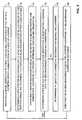
- Figure 1is a schematic illustration of a system, generally referenced 100, for automatically maneuvering a catheter within a lumen of the body of a patient, constructed and operative in accordance with an embodiment of the disclosed technique.
- Figure 2is a schematic illustration of a method by which the imaging system of the system of Figure 1 determines the coordinates of a path within the lumen, in three dimensions.
- system 100includes a joystick 102, a controller 104, a moving mechanism 106, a medical positioning system (MPS) 108, a plurality of transmitters 110A, 110B and 110C, an imaging system 112, a position detector 114, a catheter 116 and a display 118.
- Imaging system 112includes a radiation generator 120 and a radiation detector 122.
- Imaging system 112can be an X-ray system, fluoroscope, C-arm imager, computed tomography (CT), positron emission tomography (PET), ultrasound system, magnetic resonance imager (MRI), and the like.
- Moving mechanism 106can include a pair of angular movement rollers 124A and 124B, and a pair of linear movement rollers 126A and 126B, and respective moving elements (not shown) such as electric motors, actuators, and the like.
- moving mechanism 106can include other, alternative or additional elements, as long as it imparts to catheter 116 the necessary motions described herein below (e.g., piezoelectric motors which transfer linear movement through friction).
- moving mechanism 106can be disposable in order to keep it sterile.
- Controller 104includes a processor (not shown) and a storage unit (not shown) for storing information respective of a path 128, which catheter 116 should move according to, within a lumen 130 of the body (not shown) of a patient (not shown).
- Moving mechanism 106is coupled with joystick 102 and with controller 104.
- Controller 104is coupled with imaging system 112.
- MPS 108is coupled with controller 104 and with transmitters 110A, 110B and 110C.
- Position detector 114is coupled with MPS 108 by a conductor 132 (i.e., a conductive coupling).
- Display 118is coupled with MPS 108 and with imaging system 112.
- Position detector 114is located at a distal portion of catheter 116.
- Imaging system 112has at least one degree of freedom, thereby being able to take a plurality of images of the body of the patient, from different directions. Imaging system 112 provides a signal to display 118, respective of a two-dimensional image 134 of lumen 130, for display 118 to display two-dimensional image 134.
- Path 128is a three-dimensional curve between an origin 136 and a destination 138 of a distal portion (not shown) of catheter 116 relative to lumen 130. Both origin 136 and destination 138 are within a field of view of imaging system 112. Path 128 is determined during an imaging session prior to the medical operation, and stored in the storage unit.
- Controller 104calculates and constructs path 128, for example, according to a plurality of two-dimensional images obtained from lumen 130, with the aid of a C-arm imager.
- the C-armcan obtain two two-dimensional ECG gated images of lumen 130 at two different non-parallel ECG gated image planes.
- the C-armconstructs path 128 in three dimensions.
- controller 104calculates path 128 based on one or more image processing algorithms, according to contrast variations of lumen 130 relative to the background.
- imaging system 112captures an image 144 of lumen 130 on an image plane 146 in a three-dimensional coordinate system 148, and another image 150 of lumen 130 on an image plane 152 in three-dimensional coordinate system 148. Imaging system 112 is aware of the orientation between image planes 146 and 152 (i.e., the angles there between). Imaging system 112 identifies a feature 154 of lumen 130 in image 144 and a corresponding feature 156 in image 150.
- Imaging system 112determines the three-dimensional coordinates of feature 154 (or feature 156) in three-dimensional coordinate system 148, by determining the intersection of normals 158 and 160 from features 154 and 156, respectively, to image planes 146 and 152, respectively, at a point 162. Imaging system 112 performs the above procedure for other features of lumen 130, thereby constructing path 128 in three dimensions.
- a two-dimensional image which the C-arm obtains from the body of the patientcan include other lumens (not shown) in addition to lumen 130, which are located at planes different than the plane of lumen 130 (i.e., these additional lumens overlap lumen 130 in the captured image).
- the C-armcan construct a path (not shown), which passes through another lumen which in the two-dimensional image overlaps lumen 130.
- the C-armobtains another two-dimensional image of lumen 130 at another image plane, such that in the new two-dimensional image, lumen 130 is not overlapped by any other lumens.
- the coordinate systems of MPS 108 and imaging system 112are set to a common two-dimensional coordinate system, for display 118 to superimpose a representation 140 of position detector 114, on two-dimensional image 134, during the medical operation.
- This methodis described for example, in US Patent Application No. 09/949,160 , which is incorporated herewith by reference.
- the information displayed by display 118serves the physical staff to observe the location of the distal portion of catheter 116 relative to lumen 130, throughout the medical operation.
- This two-dimensional coordinate systemcan be determined for example, according to the following method.
- a first transformation model between the three-dimensional coordinate system of MPS 108 and the three-dimensional coordinate system of imaging system 112is determined.
- a second transformation model between the three-dimensional coordinate system of imaging system 112 and a two-dimensional coordinate system of imaging system 112is determined.
- the three-dimensional coordinate system of MPS 108is transformed to the three-dimensional coordinate system of imaging system 112, by applying the first transformation model to the three-dimensional coordinate system of MPS 108.
- the three-dimensional transformed coordinate system of imaging system 112is transformed to the two-dimensional coordinate system of imaging system 112, by applying the second transformation model to the three-dimensional transformed coordinate system of imaging system 112.
- the first transformation modelis determined according to a set of points in the three-dimensional coordinate system of MPS 108 and another set of points in the three-dimensional coordinate system of imaging system 112.
- the second transformation modelis determined according to external parameters of imaging system 112 (i.e., a set of points in the three-dimensional coordinate system of imaging system 112) and internal parameters of imaging system 112 (e.g., lens angle, focal length, magnification).
- path 128is a three-dimensional curve within the axillary artery (represented by lumen 130) which marks a path from the region of the first rib (i.e., origin 136) to the thyrocervical trunk (i.e., destination 138).
- the physical staffinserts catheter 116 to the body of the patient through the right brachial artery (not shown), and manually maneuvers catheter 116 to reach origin 136.
- position detector 114In response to the electromagnetic field produced by transmitters 110A, 110B and 110C, position detector 114 sends a signal to MPS 108 via conductor 132, respective of the three-dimensional position of position detector 114.
- position detector 114is coupled with MPS 108 wirelessly and without conductor 132, in which case position detector 114 sends this position signal to MPS 108 wirelessly.
- MPS 108determines the coordinates of position detector 114 according to the signal received from position detector 114.
- MPS 108sends a signal respective of the coordinates of position detector 114 to controller 104, in the three-dimensional coordinate system of MPS 108.
- MPS 108sends a signal respective of the coordinates of position detector 114 to display 118, in the two-dimensional coordinate system of imaging system 112, as described herein above.
- display 118displays two-dimensional image 134 of an operational region of lumen 130 (i.e., a section between origin 136 and destination 138) according to a signal received from imaging system 112.
- Display 118also displays representation 140 of the current location of position detector 114 (i.e., the distal portion of catheter 116), superposed on two-dimensional image 134, according to the signal received from MPS 108.
- the current location of the position detectorcan be superposed on a three-dimensional image of the lumen (e.g., the coronary tree).
- the controllercan employ a topographical representation of the lumen system of the patient, in order to control the moving mechanism to maneuver the catheter through the lumen system, from an origin to a destination within the lumen system. In this case, the controller determines the best path for the catheter to reach the destination. It is noted that the controller may change the path in real-time, depending on findings during the navigation process (e.g., blocked passages, lumen which is narrower than expected).
- the controllermodifies the path according to the feedback provided in real time by the position detector, and by comparing the actual position and orientation of the position detector with the expected position and orientation. Furthermore, the controller modifies a predefined three-dimensional path which is used as a three-dimensional roadmap for the planning process.
- the systemcan further include a processor (not shown) coupled with the MPS and with the display, and an organ monitor (not shown) such as an ECG coupled with the processor, as described in US Patent application No. 09/949,160 .
- the organ monitormonitors the organ timing signal of a monitored organ and sends a respective signal to the processor.
- the processorsends a video signal to the display respective of an image of the lumen, corresponding with the current activity-state of the monitored organ detected by the organ monitor.
- the displaydisplays an image of the lumen, according to the current activity-state.
- the displaydisplays a superposition of a representation of the position detector on a reconstructed image of the lumen, taking into account the movements of the lumen due to the timing signal of the monitored organ (e.g., the heart beat of the patient).
- the displaycan display a three-dimensional reconstructed image of the lumen, as described in US Patent application No. 09/949,160 . This three-dimensional reconstructed image is displayed relative to the coordinate system of the body of the patient.
- the medical positioning systemcan filter out the organ timing signal (i.e., producing a filtered MPS reading) and the current position of the position detector in the coordinate system of the lumen, from a multitude of positions of the position detector, in the coordinate system of the body of the patient.
- the controllerupdates the topological representation and the position of the tip of the catheter according to the filtered MPS reading.
- the controllercontrols the moving mechanism according to the updated topological representation and the updated position of the catheter.
- the displaycan display the updated topological representation and the updated representation of the distal portion of the catheter, superposed on a substantially stationary three-dimensional reconstructed image of the lumen.
- Moving mechanism 106operates according to the commands received from controller 104, to maneuver catheter 116 along path 128, from origin 136 to destination 138.
- the pair of angular movement rollers 124A and 124Btwist catheter 116 clockwise and counterclockwise relative to the longitudinal axis (not shown) of catheter 116, and the pair of linear movement rollers 126A and 126B move catheter 116 forward and backward.
- Controller 104constantly receives a signal from MPS 108 respective of three-dimensional coordinates of position detector 114 at any given time (i.e., a feedback), thereby allowing moving mechanism 106 to apply corrections to possible errors of movement along path 128. These corrections are applied in the following manner.
- Controller 104sends a signal at predetermined time increments to moving mechanism 106, to advance catheter 116 by a predetermined displacement increment. Controller 104 determines the advancement of the distal portion of catheter 116 at each time increment (according to the position signal received from MPS 108), and checks whether this advancement substantially matches the predetermined displacement by which catheter 116 was supposed to advance. In case the actual detected advancement does not match the predetermined displacement increment, controller 104 determines that catheter 116 has made contact with an obstacle (not shown) which prevents catheter 116 to advance according to path 128 (e.g., the distal portion of catheter 116 can be stuck at a bifurcation 142).
- an obstaclenot shown
- controller 104sends a signal to moving mechanism 106 to retreat catheter 116 by a selected increment backward within lumen130, and also to twist the distal portion of catheter 116 by a selected amount. After this twist, controller 104 sends a signal to moving mechanism 106 to advance catheter 116 by a predetermined displacement increment.
- moving mechanism 106can maneuver catheter 116 to overcome the obstacle and to enter the predetermined branch (in this case the thyrocervical trunk at bifurcation 142).
- controller 104can control the operation of moving mechanism 106 to maneuver catheter 116 in three-dimensions.
- system 100provides an advantage over systems in the prior art, in which the physical staff can maneuver the catheter according to a two-dimensional display, only in two dimensions.
- System 100provides automatic maneuvering of catheter 116 through lumen 130 in three dimensions, while performing feedback oriented real time corrections in order to reach destination 138 within lumen 130.
- imaging system 112can divide path 128 to different parts, and prepare the information for two-dimensional image 134, by selecting a different image plane for each part, while satisfying Equation 1.
- more than one position detectorcan be located at the distal portion of the catheter. This arrangement is crucial in case the distal portion of the catheter is provided with a “curve-back” functionality.
- the "curve-back" movementcan be provided for example, by employing Electro Active Polymers (EAP).
- EAPElectro Active Polymers
- the moving mechanismis likewise provided with the necessary elements to apply an appropriate torque to the distal portion of the catheter, to bend the distal portion.
- the displaycan display the current geometry of the distal portion.
- the controllercan obtain a more complete information respective of the geometry of the distal portion of the catheter, when the catheter is blocked by an obstacle, and thus expedite the maneuvering operation. If the controller detects that the distal portion of the catheter has unexpectedly bent, then the controller determines that the tip of the catheter has made contact with an obstacle in the lumen. The controller reaches this conclusion by comparing the detected orientation of the position detector at a given point within the lumen, with the computed slope of the path at the same point within the lumen. In case the detected orientation and the computed slope do not match, the controller determines that the catheter has met an obstacle, thereby directing the moving mechanism to operate in order to move the catheter back from the obstacle.
- controller 104In case the physical staff is unsatisfied with the automatic operation of moving mechanism 106, he can override controller 104, and manually operate moving mechanism 106 via joystick 102. The operator can intervene in any phase of operation of system 100, using joystick 102. This is a semi-automatic mode of operation of system 100, wherein controller 104 enables moving mechanism 106 to maneuver catheter 116 through the trivial portions of path 128, and the operator takes control of system 100 in the more intricate portions of path 128. In case of manual intervention, joystick 102 overcomes any automated action. Is noted that both in the automatic mode and the manual mode, the operator receives a visual feedback of the advancement of catheter 116 within lumen 130, by viewing representation 140 of the tip of catheter 116 on display 118.
- FIG. 3is a schematic illustration of a method for operating the system of Figure 1 , operative in accordance with another embodiment of the disclosed technique.
- procedure 170a signal respective of a first position of the tip of a catheter within a lumen system of a body of a patient is received.
- controller 104receives a signal from MPS 108 respective of the position of the distal portion of catheter 116, within lumen 130.
- a new position to move the catheter tois determined according to the received signal and according to a topological representation of the lumen system.
- controller 104determines a new position for catheter 116 within lumen 130, according to the current position, and according to path 128.
- a moving mechanismis operated to move the catheter to a second position, according to the new determined position.
- controller 104sends a signal to moving mechanism 106 to move catheter 116 within lumen 130, to a second position, according to the new position determined in procedure 172, in order to advance catheter 116 within lumen 130 toward destination 138.
- procedure 176it is determined whether the second position is substantially identical with the new determined position. If the outcome of the comparison is positive, then the method proceeds to procedure 170. Otherwise the method proceeds to procedure 178.
- controller 104constantly receives a signal respective of the position of the tip of catheter 116 within lumen 130, and compares the current position with the position determined in procedure 172. If controller 104 determines that the current position is substantially identical with the one determined in procedure 172, then controller 104 determines that moving mechanism 106 has advanced catheter 116 as originally planned in procedure 172. In this case, procedures 170, 172 and 174 are repeated.
- controller 104determines that the current position of the tip of catheter 116 is not identical with the one determined in procedure 172. Thus, controller 104 determines that catheter 116 has reached an obstacle, such as bifurcation 142, which prevents catheter 116 to advance within lumen 130 as planned in procedure 172.
- an obstaclesuch as bifurcation 142
- controller 104determines that catheter 116 has to be retreated within lumen 130 by a certain amount, twisted by a certain amount and then pushed forward within lumen 130, by a certain amount in order for catheter 116 to clear bifurcation 142.
- controller 104for example, sends a signal to moving mechanism 106 for linear movement rollers 126A and 126B to pull catheter 116 by a selected linear increment within lumen 130, and for angular movement rollers 124A and 124B to twist the tip of catheter 116 by a selected amount. Controller 104 then sends a signal to moving mechanism 106 for linear movement rollers 126A and 126B to push catheter 116 by another selected linear increment. The method can then return back to procedure 170 to advance catheter 116 to another position toward destination 138 within lumen 130.
- the displayis further coupled with the controller and with a pointing device, such as a mouse, tablet and stylus, cyber glove, joy stick, audio input device, and the like.
- a pointing devicesuch as a mouse, tablet and stylus, cyber glove, joy stick, audio input device, and the like.
- a userdefines a trail within the lumen system for the catheter to move along, by employing the pointing device.
- the controllerdirects the moving mechanism to move the catheter within the lumen along the defined trail, according to the entire topological representation of the lumen system. For this purpose, the controller continuously determines successive incremental paths from the current position of the catheter to a user defined position located in front of, and closest to the current position of the catheter.
- the cathetercan enter an adjacent lumen different than the one defined by the trail.
- the controllerdetects this deviation in course by detecting an unusually large difference between the current position of the tip of the catheter and the user defined position. The controller, then corrects the course by directing the moving mechanism to move the catheter back and advance it to the lumen marked by the trail.
- FIG. 4is a schematic illustration of a method for operating the system of Figure 1 , operative in accordance with a further embodiment of the disclosed technique.
- procedure 200consecutive position inputs are received from a user, to guide a catheter in real time, within a lumen system of the body of a patient.
- the usermoves a cursor on display 118 along two-dimensional image 134 of lumen 130, thereby sending consecutive position inputs to controller 104 via the pointing device.
- a user defined positionis determined for the tip of the catheter, for each received position input.
- controller 104determines a position for the tip of catheter 116 for each position input (i.e., the position of the cursor). A plurality of these positions define a trail in the lumen system.
- procedure 204the real time position of the tip of the catheter is constantly detected.
- position detector 114 of catheter 116constantly detects the current position of the tip of catheter 116.
- MPS 108determines this real time position and sends this information to controller 104. It is noted that procedures 200, 202 and 204 are performed simultaneously.
- controller 104determines a trail on the lumen system, according to the user defined positions which were determined in procedure 202. With reference to Figure 1 , controller 104 determines an incremental path between the current position of the tip of catheter 116 as detected by position detector 114, and a user defined position of the cursor located immediately in front of the current position of the tip of catheter 116. Controller 104 employs also the entire topological representation of the lumen system to determine each of the incremental paths.
- a moving mechanismis directed to incrementally move the catheter within the lumen system along each incremental path, from each real time position toward the adjacent proceeding user defined position.
- controller 104directs moving mechanism 106 to move catheter 116 incrementally within lumen 130, from the current position of the tip of catheter 116 as detected by position detector 114, to the user defined position located immediately in front of the current position of the tip of catheter 116.
- the methodreturns to procedure 204, wherein a new incremental path is determined between a newly detected position of the tip of the catheter and the user defined position located immediately in front of the newly detected position of the tip of the catheter. Controller 104, then directs moving mechanism 106 to advance catheter 116 along the new incremental path. This cycle is continuously repeated, until the tip of catheter 116 reaches the last user defined position in the trail.
- controller 104detects that the tip of catheter 116 did not reach the user defined position which was supposed to reach. Controller 104 can detect this situation for example, by detecting that the tip of catheter 116 is outside a predetermined sphere around the user defined position. Controller 104 determines a corrective movement similar to the one described herein above in connection with procedures 178 and 180, except that controller 104 directs moving mechanism 106 to pull back catheter 116 from the incorrect lumen, and enter catheter 116 into the lumen which is indicated by the trail.
Landscapes
- Health & Medical Sciences (AREA)
- Life Sciences & Earth Sciences (AREA)
- Engineering & Computer Science (AREA)
- General Health & Medical Sciences (AREA)
- Veterinary Medicine (AREA)
- Public Health (AREA)
- Animal Behavior & Ethology (AREA)
- Biomedical Technology (AREA)
- Heart & Thoracic Surgery (AREA)
- Surgery (AREA)
- Biophysics (AREA)
- Molecular Biology (AREA)
- Medical Informatics (AREA)
- Pathology (AREA)
- Pulmonology (AREA)
- Physics & Mathematics (AREA)
- Hematology (AREA)
- Anesthesiology (AREA)
- Nuclear Medicine, Radiotherapy & Molecular Imaging (AREA)
- Human Computer Interaction (AREA)
- Robotics (AREA)
- Radiology & Medical Imaging (AREA)
- Optics & Photonics (AREA)
- Apparatus For Radiation Diagnosis (AREA)
- Media Introduction/Drainage Providing Device (AREA)
- Magnetic Resonance Imaging Apparatus (AREA)
- Ultra Sonic Daignosis Equipment (AREA)
Abstract
Description
- The disclosed technique relates to medical equipment in general, and to systems for maneuvering a catheter within a lumen of a body of a patient, in particular.
- Various diagnostic and medical operations on lumens of the body of a patient, such as the circulation system, the gastrointestinal tract, the brain vessels, the bronchial tree, and the like, are preformed by inserting a catheter through the lumen. Since the catheter is generally a bulky device, it is difficult to guide it to the operational site all on its own. For this purpose, a guidewire whose diameter is substantially smaller than that of the catheter, is inserted to the operational site before inserting the catheter, and then the catheter is passed over the guidewire and guided to the operational site.
- Methods and systems for maneuvering the guidewire through the lumen to the operational site, are known in the art. Generally, the operator manipulates the movements of the guidewire, by manually pushing or pulsing the guidewire or twisting the guidewire, while he watches an image of the tip of the guidewire, against a real time two-dimensional image of the lumen (e.g., by employing a fluoroscopy angiogram). In this manner, the tip of the guidewire is maneuvered at various bifurcations of the lumens, in order to reach the operational site. The same method is employed for manipulating a catheter, only that a marker (e.g.,. an X-ray opaque material) is located on the tip of the catheter.
US Patent No. 6,594,517 B1 issued to Nevo and entitled "Method and Apparatus for Generating Controlled Torques on Objects- Particularly Objects Inside a Living Body", is directed to a system and method for applying a controlled torque on an intra-body device, to bend the tip of the intra-body device. The system includes an input device, a processing and control unit, and electronic interface, the intra-body device, a torque generating module, a location and direction module and a magnetic resonance imaging system (MRI). The MRI includes a computer, an image display, a gradient activation control unit, an MRI magnet, and a set of three orthogonal gradient coils. The torque generating module includes three micro-coils.
- The processing and control unit is connected with the input device, the electronic interface, the computer, and with the gradient activation control unit. The torque generating module and the location and direction module are located at the tip of the intra-body device. The torque generating module and the location and direction module are connected with the electronic interface. The computer is connected with the image display and with the gradient activation control unit. The gradient activation control unit is connected with the orthogonal gradient coils.
- The processing and control unit controls the electrical currents through the micro-coils, in order to cause the torque generating module to generate a resultant magnetic dipole to interact with the magnetic field produced by the MRI magnet. This interaction produces a torque of the desired direction and magnitude, in order to steer the tip of the intra-body device. The gradient activation control unit provides the processing and control unit, information respective of the electromagnetic gradient fields generated by the three orthogonal gradient coils, and the timing sequence of the activation of these coils. The image display provides a real time image of the operation field. The location and direction module provides the location and direction or orientation of the tip of the intra-body device. The computer provides the processing and control unit, the event schedule of the MRI system, to prevent image artifacts due to activation of the torque generating module, when the MRI magnets are activated for imaging.
- A stereotaxis system is employed for steering a guidewire of a catheter through the lumen, and bending the tip of the guidewire, by applying a magnetic field to the guidewire through a plurality of magnets. Magnetic fields are applied to cause the guidewire to turn in different directions.
US Patent No. 6,035,856 describes such a method. US Patent No. 6,035,856 issued to LaFontaine et al. , and entitled "Percutaneous Bypass with Branching Vessel", is directed to a method for performing a bypass on a first occlusion of a branching vessel of the aorta. A coronary artery which includes the first occlusion, and a branching vessel branch out of the aorta. A standard guide-catheter is advanced through the aorta up to the ostium of the branching vessel. An occlusion forming device is advanced through the guide-catheter into the branching vessel, to produce a second occlusion in the branching vessel. The occlusion device includes an elongate portion and a heated balloon.- The occlusion forming device is removed from the aorta through the guide-catheter and a cutting device is advanced through the guide-catheter proximal to the second occlusion. The cutting device includes an elongate member, a steerable guidewire, a proximal occlusion balloon, a distal balloon, a stent, a cutting blade, a first piece of magnetic material and a transmitter. The cutting blade is located distal to the distai balloon, the first piece of the magnetic material is located between the cutting blade and the distal balloon and the transmitter is located within the distal balloon. The distal balloon is located within the stent. The transmitter emits radio frequency signals.
- The wall of the branching vessel is cut by employing the cutting blade. The distal balloon is kept in the expanded position, in order to occlude the branching vessel after the branching vessel has been cut. The severed end of the branching vessel is steered toward a region of the coronary artery distal to the first occlusion, by maneuvering the steerable guidewire or by manipulating the first piece of the magnetic material by a second piece of magnetic material, wherein the second piece of magnetic material is located outside the body of the patient.
- The true position and the relative position of the transmitter and thus the position of the severed end of the branching vessel, is determined by employing a triangulation and coordinate mapping system. The triangulation and coordinate mapping system includes three reference electrodes which are located outside the body of the patient. Two of the reference electrodes are located on opposite sides of the heart and the third is located on the back. The three reference electrodes are used to triangulate on the transmitter.
- When the severed end of the branching vessel is properly positioned, an aperture is formed in the coronary artery distal to the first occlusion, by employing the cutting blade. The severed end of the branching vessel is inserted into the coronary artery through the aperture and the stent is expanded by inflating the distal balloon, thereby attaching the severed end of the branching vessel to the lumen of the coronary artery.
WO 03/086190 A1 - It is an object of the disclosed technique to provide a novel system for using a feedback from a position sensor located on the tip of a wire (or a catheter), to automatically maneuver and guide the tip of the catheter to a predefined designated position based on a structural roadmap of the vessel tree.
- In accordance with the disclosed technique, there is thus provided a system according to claim 1.
- The disclosed technique will be understood and appreciated more fully from the following detailed description taken in conjunction with the drawings in which:
Figure 1 is a schematic illustration of a system for automatically maneuvering a catheter within a lumen of the body of a patient, constructed and operative in accordance with an embodiment of the disclosed technique;Figure 2 is a schematic illustration of a method by which the imaging system of the system ofFigure 1 determines the coordinates of a path within the lumen, in three dimensions;Figure 3 is a schematic illustration of a method for operating the system ofFigure 1 , operative in accordance with another embodiment of the disclosed technique; andFigure 4 is a schematic illustration of a method for operating the system ofFigure 1 , operative in accordance with a further embodiment of the disclosed technique.- The disclosed technique overcomes the disadvantages of the prior art by providing a system which automatically controls the movements of a catheter to a desired location within a lumen of a patient, according to a path within the lumen and according to the current position of the tip of the catheter within the lumen, while employing the current position as a feedback to control the movement. The path which the tip of the catheter is to follow is preplanned and is determined at an imaging session prior to the operational session, by employing a dynamic imager. Alternatively, the system maneuvers the catheter within the lumen, to the desired location, according to the circulation map of the body of the patient. The operator can override the automatic operation of the system and revert to the manual mode at any time, while observing a representation of the tip of the catheter against a real time two-dimensional image of the lumen. An organ monitor, such as an electrocardiogram (ECG) for monitoring an organ timing signal of an organ can be employed with the system, to display the two-dimensional image, as well as the three-dimensional structural model of the vessel tree by taking into account the movements of the lumen caused by pulsations of the organ (e.g., the heart).
- The term "catheter" herein below, refers to an elongated body which can be inserted to a lumen of the body of a patient. The catheter can be for example, a guidewire for guiding a medical device to a certain location within the lumen, and the like. The term "topological representation" herein below, refers to a mapping of a lumen system (e.g., the circulation, the bronchial tree, the urogenital system, the renal system) of the body of the patient, which a system according to the disclosed technique employs, in order to maneuver the catheter from an origin to a destination. The mapping can be either two-dimensional or three-dimensional. Alternatively, it is noted that the term "topological representation" may include just the path to be followed in the lumen system. The term "position" herein below, refers either to the location, to the orientation or both the location and the orientation, of an object in a three-dimensional coordinate system.
- Reference is now made to
Figures 1 and2 .Figure 1 is a schematic illustration of a system, generally referenced 100, for automatically maneuvering a catheter within a lumen of the body of a patient, constructed and operative in accordance with an embodiment of the disclosed technique.Figure 2 is a schematic illustration of a method by which the imaging system of the system ofFigure 1 determines the coordinates of a path within the lumen, in three dimensions. - With reference to
Figure 1 ,system 100 includes ajoystick 102, acontroller 104, a movingmechanism 106, a medical positioning system (MPS) 108, a plurality oftransmitters imaging system 112, aposition detector 114, acatheter 116 and adisplay 118.Imaging system 112 includes aradiation generator 120 and aradiation detector 122.Imaging system 112 can be an X-ray system, fluoroscope, C-arm imager, computed tomography (CT), positron emission tomography (PET), ultrasound system, magnetic resonance imager (MRI), and the like. - Moving
mechanism 106 can include a pair ofangular movement rollers linear movement rollers mechanism 106 can include other, alternative or additional elements, as long as it imparts tocatheter 116 the necessary motions described herein below (e.g., piezoelectric motors which transfer linear movement through friction). Optionally, movingmechanism 106 can be disposable in order to keep it sterile.Controller 104 includes a processor (not shown) and a storage unit (not shown) for storing information respective of apath 128, whichcatheter 116 should move according to, within a lumen 130 of the body (not shown) of a patient (not shown). - Moving
mechanism 106 is coupled withjoystick 102 and withcontroller 104.Controller 104 is coupled withimaging system 112.MPS 108 is coupled withcontroller 104 and withtransmitters Position detector 114 is coupled withMPS 108 by a conductor 132 (i.e., a conductive coupling).Display 118 is coupled withMPS 108 and withimaging system 112.Position detector 114 is located at a distal portion ofcatheter 116. - During the medical operation, the body of the patient is located between
radiation generator 120 andradiation detector 122.Imaging system 112 has at least one degree of freedom, thereby being able to take a plurality of images of the body of the patient, from different directions.Imaging system 112 provides a signal to display 118, respective of a two-dimensional image 134 of lumen 130, fordisplay 118 to display two-dimensional image 134. Path 128 is a three-dimensional curve between anorigin 136 and adestination 138 of a distal portion (not shown) ofcatheter 116 relative to lumen 130. Bothorigin 136 anddestination 138 are within a field of view ofimaging system 112.Path 128 is determined during an imaging session prior to the medical operation, and stored in the storage unit.Controller 104 calculates and constructspath 128, for example, according to a plurality of two-dimensional images obtained from lumen 130, with the aid of a C-arm imager. For example, the C-arm can obtain two two-dimensional ECG gated images of lumen 130 at two different non-parallel ECG gated image planes. When the user indicatesorigin 136 anddestination 138, the C-arm constructs path 128 in three dimensions. It is noted thatcontroller 104 calculatespath 128 based on one or more image processing algorithms, according to contrast variations of lumen 130 relative to the background.- With further reference to
Figure 2 ,imaging system 112 captures animage 144 of lumen 130 on animage plane 146 in a three-dimensional coordinatesystem 148, and anotherimage 150 of lumen 130 on animage plane 152 in three-dimensional coordinatesystem 148.Imaging system 112 is aware of the orientation between image planes 146 and 152 (i.e., the angles there between).Imaging system 112 identifies afeature 154 of lumen 130 inimage 144 and acorresponding feature 156 inimage 150.Imaging system 112 determines the three-dimensional coordinates of feature 154 (or feature 156) in three-dimensional coordinatesystem 148, by determining the intersection ofnormals features planes point 162.Imaging system 112 performs the above procedure for other features of lumen 130, thereby constructingpath 128 in three dimensions. - A two-dimensional image which the C-arm obtains from the body of the patient, can include other lumens (not shown) in addition to lumen 130, which are located at planes different than the plane of lumen 130 (i.e., these additional lumens overlap lumen 130 in the captured image). In this case, when the user indicates
origin 136 anddestination 138, it is not evident to the C-arm that the user is interested in a path through lumen 130, and the C-arm can construct a path (not shown), which passes through another lumen which in the two-dimensional image overlaps lumen 130. Hence, the C-arm obtains another two-dimensional image of lumen 130 at another image plane, such that in the new two-dimensional image, lumen 130 is not overlapped by any other lumens. - Prior to the medical operation, the coordinate systems of
MPS 108 andimaging system 112 are set to a common two-dimensional coordinate system, fordisplay 118 to superimpose arepresentation 140 ofposition detector 114, on two-dimensional image 134, during the medical operation. This method is described for example, inUS Patent Application No. 09/949,160 display 118, serves the physical staff to observe the location of the distal portion ofcatheter 116 relative to lumen 130, throughout the medical operation. This two-dimensional coordinate system can be determined for example, according to the following method. - A first transformation model between the three-dimensional coordinate system of
MPS 108 and the three-dimensional coordinate system ofimaging system 112 is determined. A second transformation model between the three-dimensional coordinate system ofimaging system 112 and a two-dimensional coordinate system ofimaging system 112 is determined. The three-dimensional coordinate system ofMPS 108 is transformed to the three-dimensional coordinate system ofimaging system 112, by applying the first transformation model to the three-dimensional coordinate system ofMPS 108. The three-dimensional transformed coordinate system ofimaging system 112 is transformed to the two-dimensional coordinate system ofimaging system 112, by applying the second transformation model to the three-dimensional transformed coordinate system ofimaging system 112. - The first transformation model is determined according to a set of points in the three-dimensional coordinate system of
MPS 108 and another set of points in the three-dimensional coordinate system ofimaging system 112. The second transformation model is determined according to external parameters of imaging system 112 (i.e., a set of points in the three-dimensional coordinate system of imaging system 112) and internal parameters of imaging system 112 (e.g., lens angle, focal length, magnification). - Following is a description of operation of
system 100, for performing an operation on the vessels in the neck region of the patient. In this case,path 128 is a three-dimensional curve within the axillary artery (represented by lumen 130) which marks a path from the region of the first rib (i.e., origin 136) to the thyrocervical trunk (i.e., destination 138). At the stage of medical operation, the physical staff insertscatheter 116 to the body of the patient through the right brachial artery (not shown), and manuallymaneuvers catheter 116 to reachorigin 136. - At this point,
system 100 takes over, to automatically maneuvercatheter 116 todestination 138. In response to the electromagnetic field produced bytransmitters position detector 114 sends a signal toMPS 108 viaconductor 132, respective of the three-dimensional position ofposition detector 114. Alternatively,position detector 114 is coupled withMPS 108 wirelessly and withoutconductor 132, in whichcase position detector 114 sends this position signal toMPS 108 wirelessly. MPS 108 determines the coordinates ofposition detector 114 according to the signal received fromposition detector 114.MPS 108 sends a signal respective of the coordinates ofposition detector 114 tocontroller 104, in the three-dimensional coordinate system ofMPS 108.MPS 108 sends a signal respective of the coordinates ofposition detector 114 to display 118, in the two-dimensional coordinate system ofimaging system 112, as described herein above.- Throughout the medical operation,
display 118 displays two-dimensional image 134 of an operational region of lumen 130 (i.e., a section betweenorigin 136 and destination 138) according to a signal received fromimaging system 112.Display 118 also displaysrepresentation 140 of the current location of position detector 114 (i.e., the distal portion of catheter 116), superposed on two-dimensional image 134, according to the signal received fromMPS 108. Alternatively, the current location of the position detector can be superposed on a three-dimensional image of the lumen (e.g., the coronary tree). - Instead of
path 128, the controller can employ a topographical representation of the lumen system of the patient, in order to control the moving mechanism to maneuver the catheter through the lumen system, from an origin to a destination within the lumen system. In this case, the controller determines the best path for the catheter to reach the destination. It is noted that the controller may change the path in real-time, depending on findings during the navigation process (e.g., blocked passages, lumen which is narrower than expected). The controller modifies the path according to the feedback provided in real time by the position detector, and by comparing the actual position and orientation of the position detector with the expected position and orientation. Furthermore, the controller modifies a predefined three-dimensional path which is used as a three-dimensional roadmap for the planning process. - The system can further include a processor (not shown) coupled with the MPS and with the display, and an organ monitor (not shown) such as an ECG coupled with the processor, as described in
US Patent application No. 09/949,160 US Patent application No. 09/949,160 - Alternatively, the medical positioning system can filter out the organ timing signal (i.e., producing a filtered MPS reading) and the current position of the position detector in the coordinate system of the lumen, from a multitude of positions of the position detector, in the coordinate system of the body of the patient. In this case, the controller updates the topological representation and the position of the tip of the catheter according to the filtered MPS reading. The controller controls the moving mechanism according to the updated topological representation and the updated position of the catheter. Furthermore, the display can display the updated topological representation and the updated representation of the distal portion of the catheter, superposed on a substantially stationary three-dimensional reconstructed image of the lumen.
- Moving
mechanism 106 operates according to the commands received fromcontroller 104, to maneuvercatheter 116 alongpath 128, fromorigin 136 todestination 138. For this purpose, the pair ofangular movement rollers 124B twist catheter 116 clockwise and counterclockwise relative to the longitudinal axis (not shown) ofcatheter 116, and the pair oflinear movement rollers 126B move catheter 116 forward and backward.Controller 104 constantly receives a signal fromMPS 108 respective of three-dimensional coordinates ofposition detector 114 at any given time (i.e., a feedback), thereby allowing movingmechanism 106 to apply corrections to possible errors of movement alongpath 128. These corrections are applied in the following manner. Controller 104 sends a signal at predetermined time increments to movingmechanism 106, to advancecatheter 116 by a predetermined displacement increment.Controller 104 determines the advancement of the distal portion ofcatheter 116 at each time increment (according to the position signal received from MPS 108), and checks whether this advancement substantially matches the predetermined displacement by whichcatheter 116 was supposed to advance. In case the actual detected advancement does not match the predetermined displacement increment,controller 104 determines thatcatheter 116 has made contact with an obstacle (not shown) which preventscatheter 116 to advance according to path 128 (e.g., the distal portion ofcatheter 116 can be stuck at a bifurcation 142).- In this case,
controller 104 sends a signal to movingmechanism 106 to retreatcatheter 116 by a selected increment backward within lumen130, and also to twist the distal portion ofcatheter 116 by a selected amount. After this twist,controller 104 sends a signal to movingmechanism 106 to advancecatheter 116 by a predetermined displacement increment. Thus, movingmechanism 106 can maneuvercatheter 116 to overcome the obstacle and to enter the predetermined branch (in this case the thyrocervical trunk at bifurcation 142). - It is noted that due to the three-dimensional position information which
controller 104 receives as a real time feedback fromMPS 108,controller 104 can control the operation of movingmechanism 106 to maneuvercatheter 116 in three-dimensions. Thus,system 100 provides an advantage over systems in the prior art, in which the physical staff can maneuver the catheter according to a two-dimensional display, only in two dimensions.System 100 provides automatic maneuvering ofcatheter 116 through lumen 130 in three dimensions, while performing feedback oriented real time corrections in order to reachdestination 138 within lumen 130. - Imaging system 112 (e.g., a C-arm) can detect lumen 130 from different directions in order to provide the information necessary for
display 118 to display two-dimensional image 134.Imaging system 112 selects the one specific imaging direction at which the average distance ofpath 128 from an image plane (not shown), is minimal. IfXi is the distance from a pointi onpath 128 normal to the image plane, wherei = 1,2,3...N, then the minimum average distance is,
Incase path 128 follows many curves in space and deviates significantly from a two-dimensional path, then imagingsystem 112 can dividepath 128 to different parts, and prepare the information for two-dimensional image 134, by selecting a different image plane for each part, while satisfying Equation 1. - It is noted that more than one position detector can be located at the distal portion of the catheter. This arrangement is crucial in case the distal portion of the catheter is provided with a "curve-back" functionality. The "curve-back" movement can be provided for example, by employing Electro Active Polymers (EAP). The moving mechanism is likewise provided with the necessary elements to apply an appropriate torque to the distal portion of the catheter, to bend the distal portion. Moreover, with the aid of multiple position detectors, the display can display the current geometry of the distal portion.
- According to the invention, the controller can obtain a more complete information respective of the geometry of the distal portion of the catheter, when the catheter is blocked by an obstacle, and thus expedite the maneuvering operation. If the controller detects that the distal portion of the catheter has unexpectedly bent, then the controller determines that the tip of the catheter has made contact with an obstacle in the lumen. The controller reaches this conclusion by comparing the detected orientation of the position detector at a given point within the lumen, with the computed slope of the path at the same point within the lumen. In case the detected orientation and the computed slope do not match, the controller determines that the catheter has met an obstacle, thereby directing the moving mechanism to operate in order to move the catheter back from the obstacle.
- In case the physical staff is unsatisfied with the automatic operation of moving
mechanism 106, he can overridecontroller 104, and manually operate movingmechanism 106 viajoystick 102. The operator can intervene in any phase of operation ofsystem 100, usingjoystick 102. This is a semi-automatic mode of operation ofsystem 100, whereincontroller 104 enables movingmechanism 106 to maneuvercatheter 116 through the trivial portions ofpath 128, and the operator takes control ofsystem 100 in the more intricate portions ofpath 128. In case of manual intervention,joystick 102 overcomes any automated action. Is noted that both in the automatic mode and the manual mode, the operator receives a visual feedback of the advancement ofcatheter 116 within lumen 130, by viewingrepresentation 140 of the tip ofcatheter 116 ondisplay 118. - Reference is now made to
Figure 3 , which is a schematic illustration of a method for operating the system ofFigure 1 , operative in accordance with another embodiment of the disclosed technique. Inprocedure 170, a signal respective of a first position of the tip of a catheter within a lumen system of a body of a patient is received. With reference toFigure 1 ,controller 104 receives a signal fromMPS 108 respective of the position of the distal portion ofcatheter 116, within lumen 130. - In
procedure 172, a new position to move the catheter to, is determined according to the received signal and according to a topological representation of the lumen system. With reference toFigure 1 ,controller 104 determines a new position forcatheter 116 within lumen 130, according to the current position, and according topath 128. - In
procedure 174, a moving mechanism is operated to move the catheter to a second position, according to the new determined position. With reference toFigure 1 ,controller 104 sends a signal to movingmechanism 106 to movecatheter 116 within lumen 130, to a second position, according to the new position determined inprocedure 172, in order to advancecatheter 116 within lumen 130 towarddestination 138. - In
procedure 176, it is determined whether the second position is substantially identical with the new determined position. If the outcome of the comparison is positive, then the method proceeds toprocedure 170. Otherwise the method proceeds toprocedure 178. - With reference to
Figure 1 ,controller 104 constantly receives a signal respective of the position of the tip ofcatheter 116 within lumen 130, and compares the current position with the position determined inprocedure 172. Ifcontroller 104 determines that the current position is substantially identical with the one determined inprocedure 172, thencontroller 104 determines that movingmechanism 106 has advancedcatheter 116 as originally planned inprocedure 172. In this case,procedures - With reference to
Figure 1 ,controller 104 determines that the current position of the tip ofcatheter 116 is not identical with the one determined inprocedure 172. Thus,controller 104 determines thatcatheter 116 has reached an obstacle, such asbifurcation 142, which preventscatheter 116 to advance within lumen 130 as planned inprocedure 172. - In
procedure 178, at least one corrective movement for moving the catheter is determined. With reference toFigure 1 ,controller 104 for example, determines thatcatheter 116 has to be retreated within lumen 130 by a certain amount, twisted by a certain amount and then pushed forward within lumen 130, by a certain amount in order forcatheter 116 toclear bifurcation 142. - In
procedure 180, the moving mechanism is directed to move the catheter according to the determined corrective movement. With reference toFigure 1 ,controller 104 for example, sends a signal to movingmechanism 106 forlinear movement rollers catheter 116 by a selected linear increment within lumen 130, and forangular movement rollers catheter 116 by a selected amount.Controller 104 then sends a signal to movingmechanism 106 forlinear movement rollers catheter 116 by another selected linear increment. The method can then return back toprocedure 170 to advancecatheter 116 to another position towarddestination 138 within lumen 130. - According to another aspect of the disclosed technique, the display is further coupled with the controller and with a pointing device, such as a mouse, tablet and stylus, cyber glove, joy stick, audio input device, and the like. A user defines a trail within the lumen system for the catheter to move along, by employing the pointing device. The controller directs the moving mechanism to move the catheter within the lumen along the defined trail, according to the entire topological representation of the lumen system. For this purpose, the controller continuously determines successive incremental paths from the current position of the catheter to a user defined position located in front of, and closest to the current position of the catheter.
- At a bifurcation, the catheter can enter an adjacent lumen different than the one defined by the trail. In this case, the controller detects this deviation in course by detecting an unusually large difference between the current position of the tip of the catheter and the user defined position. The controller, then corrects the course by directing the moving mechanism to move the catheter back and advance it to the lumen marked by the trail.
- Reference is now made to
Figure 4 , which is a schematic illustration of a method for operating the system ofFigure 1 , operative in accordance with a further embodiment of the disclosed technique. Inprocedure 200, consecutive position inputs are received from a user, to guide a catheter in real time, within a lumen system of the body of a patient. With reference toFigure 1 , the user moves a cursor ondisplay 118 along two-dimensional image 134 of lumen 130, thereby sending consecutive position inputs tocontroller 104 via the pointing device. - In
procedure 202, a user defined position is determined for the tip of the catheter, for each received position input. With reference toFigure 1 , as the user moves the cursor andcontroller 104 receives position inputs from the pointing device,controller 104 determines a position for the tip ofcatheter 116 for each position input (i.e., the position of the cursor). A plurality of these positions define a trail in the lumen system. - In
procedure 204, the real time position of the tip of the catheter is constantly detected. With reference toFigure 1 ,position detector 114 ofcatheter 116 constantly detects the current position of the tip ofcatheter 116.MPS 108 determines this real time position and sends this information tocontroller 104. It is noted thatprocedures - In
procedure 206, successive incremental paths are continuously determined along a trail defined by the user defined positions, between the real time position of the tip of the catheter and the adjacent proceeding user defined position, according to a topological representation of the lumen system.Controller 104 determines a trail on the lumen system, according to the user defined positions which were determined inprocedure 202. With reference toFigure 1 ,controller 104 determines an incremental path between the current position of the tip ofcatheter 116 as detected byposition detector 114, and a user defined position of the cursor located immediately in front of the current position of the tip ofcatheter 116.Controller 104 employs also the entire topological representation of the lumen system to determine each of the incremental paths. - In
procedure 208, a moving mechanism is directed to incrementally move the catheter within the lumen system along each incremental path, from each real time position toward the adjacent proceeding user defined position. With reference toFigure 1 ,controller 104 directs movingmechanism 106 to movecatheter 116 incrementally within lumen 130, from the current position of the tip ofcatheter 116 as detected byposition detector 114, to the user defined position located immediately in front of the current position of the tip ofcatheter 116. - Following
procedure 208, the method returns toprocedure 204, wherein a new incremental path is determined between a newly detected position of the tip of the catheter and the user defined position located immediately in front of the newly detected position of the tip of the catheter.Controller 104, then directs movingmechanism 106 to advancecatheter 116 along the new incremental path. This cycle is continuously repeated, until the tip ofcatheter 116 reaches the last user defined position in the trail. - There can be a situation that at a bifurcation in the lumen system,
catheter 116 enters an adjacent lumen not included in the trail. In this case,controller 104 detects that the tip ofcatheter 116 did not reach the user defined position which was supposed to reach.Controller 104 can detect this situation for example, by detecting that the tip ofcatheter 116 is outside a predetermined sphere around the user defined position.Controller 104 determines a corrective movement similar to the one described herein above in connection withprocedures controller 104 directs movingmechanism 106 to pull backcatheter 116 from the incorrect lumen, and entercatheter 116 into the lumen which is indicated by the trail. - It will be appreciated by persons skilled in the art that the disclosed technique is not limited to what has been particularly shown and described hereinabove. Rather the scope of the disclosed technique is defined only by the claims, which follow.

Claims (16)
- System (100) for guiding a catheter (116) through a lumen system (130) of a body of a patient, to a predetermined location within the lumen system (130), the system comprising:a medical positioning system (108) including at least one position detector (114), said at least one position detector (114) being firmly attached to a distal portion of said catheter (116), said medical positioning system (108) determining the position of said at least one position detector (114);a moving mechanism (106) coupled with said catheter (116); anda controller (104) coupled with said medical positioning system (108) and with said moving mechanism (106), for controlling the operation of said moving mechanism (106) to move said catheter (116) to said predetermined location, according to said position and according to a topological representation of at least a portion of said lumen system (130), said controller (104) establishing a path in said lumen system from said topological representation of the lumen system (130), said controller (104) determining a first position of said catheter (116) in said path according to said position respective of the first position of said distal portion of said catheter (116), said controller (104) also determining a new position to which said catheter (116) is to be moved based on said determined first position and according to said path established from said topological representation, said controller (104) operating said moving mechanism (106) to move said catheter (116) to a second position, according to said new determined position; wherein, when said second position is substantially identical with said new determined position, said controller (104) determining a further new position on said path to which said catheter (116) is to be moved,characterized in that, when said second position is not identical with said new determined position, said controller (104) determining at least one corrective movement for said catheter (116), when the orientation of said distal portion at a certain location within said lumen system (130) is different than at least one slope of said three dimensional path at said certain location.
- The system (100) according to claim 1, further comprising:an imaging system (112) for detecting an image of said at least one portion; anda superimposition processor coupled with said medical positioning system (108) and with said imaging system (112), said superimposition processor superimposing a representation of said distal portion on said image, to be displayed on a display (118) coupled with said superimposition processor.
- The system (100) according to claim 2, wherein said superimposition processor superimposes said topological representation on said image, to be displayed on said display (118).
- The system (100) according to claim 2, or 3 wherein said display (118) displays a curve respective of the shape of said distal portion, according to said coordinate signal.
- The system (100) according to claim 2, 3 or 4, wherein said imaging system (112) is selected from the list consisting of:X-ray table;fluoroscope;C-arm imager;computed tomography;magnetic resonance imager:positron emission tomography; andultrasound system.
- The system (100) according to any one of the preceding claims, further comprising an organ monitor coupled with a monitored organ of said body and with said medical positioning system (108), said monitored organ being coupled with said lumen system (130), said organ monitor monitoring an organ timing signal of said monitored organ and of said lumen system(130), wherein said controller (104) updates said topological representation and said position, according to said organ timing signal; and
wherein said controller (104) controls the operation of said moving mechanism (106) according to at least one of an updated topological representation and an updated position of said distal portion. - The system (100) according to claim 6, further comprising a processor coupled with said medical positioning system, said processor updating said topological representation and a representation of said distal portion according to said organ timing signal, said processor producing a reconstructed image of said at least one portion according to said organ timing signal, said processor superposing at least one of an updated topological representation and an updated representation of said distal portion on said reconstructed image, to be displayed on a display (118) coupled with said processor.
- The system (106) according to claim 6, or 7 wherein said argan monitor is
selected from the list consisting of:electrocardiogram; andfiltered MPS reading. - The system (100) according to any one of the preceding claims, wherein said moving mechanism (106) is disposable.
- The system (100) according to any one of the preceding claims, wherein said moving mechanism (106) comprises:at least one moving element;a plurality of angular movement rollers (124A, 124B) coupled with said at least one moving element, said angular movement rollers (124A, 124B) twisting said catheter (116) by a selected amount about a longitudinal axis of said catheter (116); anda plurality of linear movement rollers (126A, 126B) coupled with said at least one moving element, said linear movement rollers (126A, 126B) moving said catheter (116) along said longitudinal axis.
- The system (100) according to any one of the preceding claims, further comprising a joystick (102) coupled with said moving element for manually operating said moving mechanism (106).
- The system (100) according to any one of the preceding claims, wherein the coupling between said medical positioning system (108) and said at least one position detector (114) is selected from the list consisting of:conductive; andwireless.
- The system (100) according to any one of the preceding claims, wherein said topological representation is a preplanned path between an origin and said predetermined location.
- The system (110) according to any one of the preceding claims, wherein said catheter (116) is in form of a guidewire.
- The system (100) according to any one of the preceding claims, wherein at least a portion of said catheter (116) is made of an Electro Active Polymer.
- The system (100) according to any one of the preceding claims, wherein said at least one corrective movement includes retreating said catheter (116) backward within said lumen system (130), said controller (104) directing said moving mechanism (106) to move said catheter (116) according to said determined corrective movement.
Applications Claiming Priority (3)
| Application Number | Priority Date | Filing Date | Title |
|---|---|---|---|
| US10/800,129US7811294B2 (en) | 2004-03-08 | 2004-03-08 | Automatic guidewire maneuvering system and method |
| US10/940,423US8055327B2 (en) | 2004-03-08 | 2004-09-14 | Automatic guidewire maneuvering system and method |
| PCT/IL2005/000227WO2005084122A2 (en) | 2004-03-08 | 2005-02-23 | Automatic guidewire maneuvering system and method |
Publications (3)
| Publication Number | Publication Date |
|---|---|
| EP1732437A2 EP1732437A2 (en) | 2006-12-20 |
| EP1732437A4 EP1732437A4 (en) | 2009-06-03 |
| EP1732437B1true EP1732437B1 (en) | 2012-01-04 |
Family
ID=34912623
Family Applications (1)
| Application Number | Title | Priority Date | Filing Date |
|---|---|---|---|
| EP05709124AExpired - LifetimeEP1732437B1 (en) | 2004-03-08 | 2005-02-23 | Automatic guidewire maneuvering system |
Country Status (6)
| Country | Link |
|---|---|
| US (3) | US7811294B2 (en) |
| EP (1) | EP1732437B1 (en) |
| JP (1) | JP5285270B2 (en) |
| AT (1) | ATE539790T1 (en) |
| CA (1) | CA2557662C (en) |
| WO (1) | WO2005084122A2 (en) |
Cited By (1)
| Publication number | Priority date | Publication date | Assignee | Title |
|---|---|---|---|---|
| US11266424B2 (en) | 2017-06-20 | 2022-03-08 | Siemens Healthcare Gmbh | Autonomous catheterization assembly |
Families Citing this family (185)
| Publication number | Priority date | Publication date | Assignee | Title |
|---|---|---|---|---|
| US9572519B2 (en) | 1999-05-18 | 2017-02-21 | Mediguide Ltd. | Method and apparatus for invasive device tracking using organ timing signal generated from MPS sensors |
| US9833167B2 (en)* | 1999-05-18 | 2017-12-05 | Mediguide Ltd. | Method and system for superimposing virtual anatomical landmarks on an image |
| US7386339B2 (en) | 1999-05-18 | 2008-06-10 | Mediguide Ltd. | Medical imaging and navigation system |
| US8442618B2 (en)* | 1999-05-18 | 2013-05-14 | Mediguide Ltd. | Method and system for delivering a medical device to a selected position within a lumen |
| US7778688B2 (en)* | 1999-05-18 | 2010-08-17 | MediGuide, Ltd. | System and method for delivering a stent to a selected position within a lumen |
| US7840252B2 (en) | 1999-05-18 | 2010-11-23 | MediGuide, Ltd. | Method and system for determining a three dimensional representation of a tubular organ |
| US7635342B2 (en)* | 2001-05-06 | 2009-12-22 | Stereotaxis, Inc. | System and methods for medical device advancement and rotation |
| US7998062B2 (en) | 2004-03-29 | 2011-08-16 | Superdimension, Ltd. | Endoscope structures and techniques for navigating to a target in branched structure |
| DE10239673A1 (en)* | 2002-08-26 | 2004-03-11 | Markus Schwarz | Device for machining parts |
| US20050054927A1 (en)* | 2003-09-10 | 2005-03-10 | Scott Love | System and method for using scheduled protocol codes to automatically configure ultrasound imaging systems |
| EP2113189B1 (en) | 2003-09-15 | 2013-09-04 | Covidien LP | System of accessories for use with bronchoscopes |
| EP2316328B1 (en) | 2003-09-15 | 2012-05-09 | Super Dimension Ltd. | Wrap-around holding device for use with bronchoscopes |
| US8764725B2 (en) | 2004-02-09 | 2014-07-01 | Covidien Lp | Directional anchoring mechanism, method and applications thereof |
| US7811294B2 (en)* | 2004-03-08 | 2010-10-12 | Mediguide Ltd. | Automatic guidewire maneuvering system and method |
| US8515527B2 (en)* | 2004-10-13 | 2013-08-20 | General Electric Company | Method and apparatus for registering 3D models of anatomical regions of a heart and a tracking system with projection images of an interventional fluoroscopic system |
| US8257302B2 (en)* | 2005-05-10 | 2012-09-04 | Corindus, Inc. | User interface for remote control catheterization |
| US8002704B2 (en)* | 2005-05-25 | 2011-08-23 | General Electric Company | Method and system for determining contact along a surface of an ultrasound probe |
| DE102005028226A1 (en)* | 2005-06-17 | 2006-12-28 | Siemens Ag | Device for controlling a magnetic element in the body of a patient |
| US8784336B2 (en) | 2005-08-24 | 2014-07-22 | C. R. Bard, Inc. | Stylet apparatuses and methods of manufacture |
| DE102005045073B4 (en) | 2005-09-21 | 2012-03-22 | Siemens Ag | A method of visually assisting invasive examination or treatment of the heart using an invasive instrument |
| DE102005051102B4 (en)* | 2005-10-24 | 2011-02-24 | Cas Innovations Gmbh & Co. Kg | System for medical navigation |
| EP1901232B1 (en)* | 2006-09-18 | 2011-03-30 | Mediguide Ltd. | Method and system for navigating through an occluded tubular organ |
| US20080147086A1 (en)* | 2006-10-05 | 2008-06-19 | Marcus Pfister | Integrating 3D images into interventional procedures |
| JP5159086B2 (en)* | 2006-10-31 | 2013-03-06 | 株式会社東芝 | Ultrasonic diagnostic apparatus and catheter navigation system |
| EP3260042B1 (en) | 2006-11-10 | 2020-07-15 | Covidien LP | Adaptive navigation technique for navigating a catheter through a body channel or cavity |
| US20080167639A1 (en)* | 2007-01-08 | 2008-07-10 | Superdimension Ltd. | Methods for localized intra-body treatment of tissue |
| US9305334B2 (en) | 2007-03-08 | 2016-04-05 | Sync-Rx, Ltd. | Luminal background cleaning |
| US8781193B2 (en) | 2007-03-08 | 2014-07-15 | Sync-Rx, Ltd. | Automatic quantitative vessel analysis |
| US10716528B2 (en) | 2007-03-08 | 2020-07-21 | Sync-Rx, Ltd. | Automatic display of previously-acquired endoluminal images |
| US11197651B2 (en) | 2007-03-08 | 2021-12-14 | Sync-Rx, Ltd. | Identification and presentation of device-to-vessel relative motion |
| US9375164B2 (en) | 2007-03-08 | 2016-06-28 | Sync-Rx, Ltd. | Co-use of endoluminal data and extraluminal imaging |
| US9968256B2 (en) | 2007-03-08 | 2018-05-15 | Sync-Rx Ltd. | Automatic identification of a tool |
| US9629571B2 (en) | 2007-03-08 | 2017-04-25 | Sync-Rx, Ltd. | Co-use of endoluminal data and extraluminal imaging |
| WO2008107905A2 (en) | 2007-03-08 | 2008-09-12 | Sync-Rx, Ltd. | Imaging and tools for use with moving organs |
| US11064964B2 (en) | 2007-03-08 | 2021-07-20 | Sync-Rx, Ltd | Determining a characteristic of a lumen by measuring velocity of a contrast agent |
| US20080234576A1 (en)* | 2007-03-23 | 2008-09-25 | General Electric Company | System and method to track movement of a tool in percutaneous replacement of a heart valve |
| US20080287783A1 (en)* | 2007-05-16 | 2008-11-20 | General Electric Company | System and method of tracking delivery of an imaging probe |
| US8428690B2 (en) | 2007-05-16 | 2013-04-23 | General Electric Company | Intracardiac echocardiography image reconstruction in combination with position tracking system |
| US7940972B2 (en)* | 2007-05-16 | 2011-05-10 | General Electric Company | System and method of extended field of view image acquisition of an imaged subject |
| US8527032B2 (en)* | 2007-05-16 | 2013-09-03 | General Electric Company | Imaging system and method of delivery of an instrument to an imaged subject |
| US8057397B2 (en)* | 2007-05-16 | 2011-11-15 | General Electric Company | Navigation and imaging system sychronized with respiratory and/or cardiac activity |
| US8989842B2 (en) | 2007-05-16 | 2015-03-24 | General Electric Company | System and method to register a tracking system with intracardiac echocardiography (ICE) imaging system |
| US8213693B1 (en) | 2007-05-16 | 2012-07-03 | General Electric Company | System and method to track and navigate a tool through an imaged subject |
| US7909767B2 (en)* | 2007-05-16 | 2011-03-22 | General Electric Company | Method for minimizing tracking system interference |
| US8790262B2 (en)* | 2007-05-16 | 2014-07-29 | General Electric Company | Method for implementing an imaging and navigation system |
| US9055883B2 (en)* | 2007-05-16 | 2015-06-16 | General Electric Company | Surgical navigation system with a trackable ultrasound catheter |
| US20080287805A1 (en)* | 2007-05-16 | 2008-11-20 | General Electric Company | System and method to guide an instrument through an imaged subject |
| US8364242B2 (en) | 2007-05-17 | 2013-01-29 | General Electric Company | System and method of combining ultrasound image acquisition with fluoroscopic image acquisition |
| EP2192855B1 (en)* | 2007-07-09 | 2020-03-25 | Covidien LP | Patent breathing modeling |
| US8905920B2 (en) | 2007-09-27 | 2014-12-09 | Covidien Lp | Bronchoscope adapter and method |
| US10751509B2 (en) | 2007-11-26 | 2020-08-25 | C. R. Bard, Inc. | Iconic representations for guidance of an indwelling medical device |
| US10524691B2 (en) | 2007-11-26 | 2020-01-07 | C. R. Bard, Inc. | Needle assembly including an aligned magnetic element |
| ES2465915T3 (en) | 2007-11-26 | 2014-06-09 | C.R. Bard, Inc. | Integrated system for intravascular catheter placement |
| US8781555B2 (en) | 2007-11-26 | 2014-07-15 | C. R. Bard, Inc. | System for placement of a catheter including a signal-generating stylet |
| US9521961B2 (en) | 2007-11-26 | 2016-12-20 | C. R. Bard, Inc. | Systems and methods for guiding a medical instrument |
| US9649048B2 (en) | 2007-11-26 | 2017-05-16 | C. R. Bard, Inc. | Systems and methods for breaching a sterile field for intravascular placement of a catheter |
| JP5491700B2 (en)* | 2008-02-14 | 2014-05-14 | 株式会社東芝 | Data processing apparatus and X-ray apparatus |
| WO2009122273A2 (en) | 2008-04-03 | 2009-10-08 | Superdimension, Ltd. | Magnetic interference detection system and method |
| WO2009137410A1 (en)* | 2008-05-06 | 2009-11-12 | Corindus Ltd. | Catheter system |
| US8218846B2 (en) | 2008-05-15 | 2012-07-10 | Superdimension, Ltd. | Automatic pathway and waypoint generation and navigation method |
| EP2297673B1 (en) | 2008-06-03 | 2020-04-22 | Covidien LP | Feature-based registration method |
| US8218847B2 (en) | 2008-06-06 | 2012-07-10 | Superdimension, Ltd. | Hybrid registration method |
| EP2303385B1 (en) | 2008-06-19 | 2013-12-11 | Sync-RX, Ltd. | Stepwise advancement of a medical tool |
| US8932207B2 (en) | 2008-07-10 | 2015-01-13 | Covidien Lp | Integrated multi-functional endoscopic tool |
| US9901714B2 (en) | 2008-08-22 | 2018-02-27 | C. R. Bard, Inc. | Catheter assembly including ECG sensor and magnetic assemblies |
| EP2320990B2 (en) | 2008-08-29 | 2023-05-31 | Corindus, Inc. | Catheter control system and graphical user interface |
| US8594799B2 (en) | 2008-10-31 | 2013-11-26 | Advanced Bionics | Cochlear electrode insertion |
| US10362962B2 (en) | 2008-11-18 | 2019-07-30 | Synx-Rx, Ltd. | Accounting for skipped imaging locations during movement of an endoluminal imaging probe |
| US8855744B2 (en) | 2008-11-18 | 2014-10-07 | Sync-Rx, Ltd. | Displaying a device within an endoluminal image stack |
| US9974509B2 (en) | 2008-11-18 | 2018-05-22 | Sync-Rx Ltd. | Image super enhancement |
| US9095313B2 (en) | 2008-11-18 | 2015-08-04 | Sync-Rx, Ltd. | Accounting for non-uniform longitudinal motion during movement of an endoluminal imaging probe |
| US9101286B2 (en) | 2008-11-18 | 2015-08-11 | Sync-Rx, Ltd. | Apparatus and methods for determining a dimension of a portion of a stack of endoluminal data points |
| US9144394B2 (en) | 2008-11-18 | 2015-09-29 | Sync-Rx, Ltd. | Apparatus and methods for determining a plurality of local calibration factors for an image |
| US11064903B2 (en) | 2008-11-18 | 2021-07-20 | Sync-Rx, Ltd | Apparatus and methods for mapping a sequence of images to a roadmap image |
| JP5404066B2 (en)* | 2009-01-13 | 2014-01-29 | 株式会社東芝 | Medical image display system |
| US8632468B2 (en)* | 2009-02-25 | 2014-01-21 | Koninklijke Philips N.V. | Method, system and devices for transjugular intrahepatic portosystemic shunt (TIPS) procedures |
| EP2408509B1 (en) | 2009-03-18 | 2023-08-09 | Corindus, Inc. | Remote catheter system with steerable catheter |
| US8611984B2 (en) | 2009-04-08 | 2013-12-17 | Covidien Lp | Locatable catheter |
| JP2012528604A (en)* | 2009-06-01 | 2012-11-15 | コーニンクレッカ フィリップス エレクトロニクス エヌ ヴィ | Distance-based location tracking method and system |
| WO2010144402A2 (en) | 2009-06-08 | 2010-12-16 | Surgivision, Inc. | Mri-guided surgical systems with preset scan planes |
| US9532724B2 (en) | 2009-06-12 | 2017-01-03 | Bard Access Systems, Inc. | Apparatus and method for catheter navigation using endovascular energy mapping |
| CN102625670B (en) | 2009-06-16 | 2015-07-15 | 核磁共振成像介入技术有限公司 | MRI-guided devices and MRI-guided interventional systems that can track and generate dynamic visualizations of the devices in near real time |
| EP2464407A4 (en) | 2009-08-10 | 2014-04-02 | Bard Access Systems Inc | Devices and methods for endovascular electrography |
| EP2488245B1 (en) | 2009-10-12 | 2019-02-20 | Corindus, Inc. | Catheter system with percutaneous device movement algorithm |
| US9962229B2 (en) | 2009-10-12 | 2018-05-08 | Corindus, Inc. | System and method for navigating a guide wire |
| US9211403B2 (en) | 2009-10-30 | 2015-12-15 | Advanced Bionics, Llc | Steerable stylet |
| RU2555381C2 (en)* | 2009-11-12 | 2015-07-10 | Конинклейке Филипс Электроникс Н.В. | Guidance system and catheter system |
| US20110184238A1 (en)* | 2010-01-28 | 2011-07-28 | The Penn State Research Foundation | Image-based global registration system and method applicable to bronchoscopy guidance |
| JP5650248B2 (en) | 2010-02-01 | 2015-01-07 | コビディエン エルピー | Region expansion algorithm |
| WO2011097312A1 (en) | 2010-02-02 | 2011-08-11 | C.R. Bard, Inc. | Apparatus and method for catheter navigation and tip location |
| EP3583978A1 (en)* | 2010-03-02 | 2019-12-25 | Corindus Inc. | Robotic catheter system with variable speed control |
| US9820695B2 (en) | 2010-03-29 | 2017-11-21 | St. Jude Medical International Holding S.àr.l. | Method for detecting contact with the wall of a region of interest |
| WO2011137336A1 (en)* | 2010-04-30 | 2011-11-03 | President And Fellows Of Harvard College | Motion compensating catheter device |
| EP2912999B1 (en) | 2010-05-28 | 2022-06-29 | C. R. Bard, Inc. | Apparatus for use with needle insertion guidance system |
| EP4122385A1 (en) | 2010-05-28 | 2023-01-25 | C. R. Bard, Inc. | Insertion guidance system for needles and medical components |
| US10582834B2 (en) | 2010-06-15 | 2020-03-10 | Covidien Lp | Locatable expandable working channel and method |
| US8672837B2 (en) | 2010-06-24 | 2014-03-18 | Hansen Medical, Inc. | Methods and devices for controlling a shapeable medical device |
| US20120035596A1 (en)* | 2010-08-04 | 2012-02-09 | Tegg Troy T | Disposable Drive Interface for Longitudinal Movement of an Elongate Medical Device |
| BR112013002431B1 (en) | 2010-08-20 | 2021-06-29 | C.R. Bard, Inc | SYSTEM FOR RECONFIRMING THE POSITION OF A CATHETER INSIDE A PATIENT |
| US9833293B2 (en) | 2010-09-17 | 2017-12-05 | Corindus, Inc. | Robotic catheter system |
| WO2012059867A1 (en)* | 2010-11-05 | 2012-05-10 | Koninklijke Philips Electronics N.V. | Imaging apparatus for imaging an object |
| WO2012077011A1 (en)* | 2010-12-09 | 2012-06-14 | Koninklijke Philips Electronics N.V. | Interventional apparatus activated computed tomography (ct) |
| US8764683B2 (en) | 2010-12-29 | 2014-07-01 | Mediguide Ltd. | Medical device guidewire with a position sensor |
| US8636718B2 (en) | 2010-12-30 | 2014-01-28 | St. Jude Medical, Atrial Fibrillation Division, Inc. | Method of assembling a positioning sensor and associated wiring on a medical tool |
| JP5430599B2 (en)* | 2011-03-30 | 2014-03-05 | 株式会社デンソーアイティーラボラトリ | Input device and information providing method using input device |
| JP2014209930A (en)* | 2011-08-31 | 2014-11-13 | テルモ株式会社 | Navigation system for respiration area |
| WO2013036909A1 (en)* | 2011-09-09 | 2013-03-14 | Children's National Medical Center | Enhanced control of flexible endoscopes through human-machine interface |
| US20130303944A1 (en) | 2012-05-14 | 2013-11-14 | Intuitive Surgical Operations, Inc. | Off-axis electromagnetic sensor |
| US9387048B2 (en) | 2011-10-14 | 2016-07-12 | Intuitive Surgical Operations, Inc. | Catheter sensor systems |
| JP6430831B2 (en)* | 2011-10-14 | 2018-11-28 | インテュイティブ サージカル オペレーションズ, インコーポレイテッド | Catheter system |
| US9452276B2 (en) | 2011-10-14 | 2016-09-27 | Intuitive Surgical Operations, Inc. | Catheter with removable vision probe |
| US10238837B2 (en) | 2011-10-14 | 2019-03-26 | Intuitive Surgical Operations, Inc. | Catheters with control modes for interchangeable probes |
| JP5836760B2 (en)* | 2011-11-04 | 2015-12-24 | キヤノン株式会社 | Acoustic wave acquisition apparatus and acoustic wave acquisition method |
| CA2856519C (en)* | 2011-11-22 | 2020-11-03 | Ascension Technology Corporation | Tracking a guidewire |
| US10363102B2 (en)* | 2011-12-30 | 2019-07-30 | Mako Surgical Corp. | Integrated surgery method |
| JP6290099B2 (en) | 2012-02-03 | 2018-03-07 | インテュイティブ サージカル オペレーションズ, インコーポレイテッド | Steerable flexible needle with implantable shape sensing function |
| WO2013132501A1 (en)* | 2012-03-07 | 2013-09-12 | M.S.T. Medical Surgery Technologies Ltd. | Overall endoscopic control system |
| US9364640B2 (en) | 2012-05-07 | 2016-06-14 | St. Jude Medical Atrial Fibrillation Division, Inc. | Medical device guidewire with helical cutout and coating |
| EP2863802B1 (en) | 2012-06-26 | 2020-11-04 | Sync-RX, Ltd. | Flow-related image processing in luminal organs |
| US9183354B2 (en) | 2012-08-15 | 2015-11-10 | Musc Foundation For Research Development | Systems and methods for image guided surgery |
| JP6310463B2 (en)* | 2012-10-05 | 2018-04-11 | コーニンクレッカ フィリップス エヌ ヴェKoninklijke Philips N.V. | X-ray beam collimation control |
| US9623211B2 (en)* | 2013-03-13 | 2017-04-18 | The Spectranetics Corporation | Catheter movement control |
| US9057600B2 (en) | 2013-03-13 | 2015-06-16 | Hansen Medical, Inc. | Reducing incremental measurement sensor error |
| US9014851B2 (en) | 2013-03-15 | 2015-04-21 | Hansen Medical, Inc. | Systems and methods for tracking robotically controlled medical instruments |
| US10271810B2 (en)* | 2013-04-02 | 2019-04-30 | St. Jude Medical International Holding S.à r. l. | Enhanced compensation of motion in a moving organ using processed reference sensor data |
| US11020016B2 (en) | 2013-05-30 | 2021-06-01 | Auris Health, Inc. | System and method for displaying anatomy and devices on a movable display |
| US9237936B2 (en) | 2013-07-12 | 2016-01-19 | Pacesetter, Inc. | System and method for integrating candidate implant location test results with real-time tissue images for use with implantable device leads |
| JP5675930B2 (en)* | 2013-10-28 | 2015-02-25 | 株式会社東芝 | X-ray diagnostic equipment |
| WO2015120256A2 (en) | 2014-02-06 | 2015-08-13 | C.R. Bard, Inc. | Systems and methods for guidance and placement of an intravascular device |
| US9247895B2 (en) | 2014-03-21 | 2016-02-02 | Pacesetter, Inc. | Systems and methods for performing deep brain stimulation |
| US9999772B2 (en) | 2014-04-03 | 2018-06-19 | Pacesetter, Inc. | Systems and method for deep brain stimulation therapy |
| WO2015165736A1 (en)* | 2014-04-29 | 2015-11-05 | Koninklijke Philips N.V. | Device for determining a specific position of a catheter |
| US10952593B2 (en) | 2014-06-10 | 2021-03-23 | Covidien Lp | Bronchoscope adapter |
| US9770216B2 (en) | 2014-07-02 | 2017-09-26 | Covidien Lp | System and method for navigating within the lung |
| CN106232010B (en) | 2014-07-02 | 2020-03-31 | 柯惠有限合伙公司 | System and method for detecting trachea |
| CN106659453B (en) | 2014-07-02 | 2020-05-26 | 柯惠有限合伙公司 | System and method for segmenting lungs |
| US20160000414A1 (en) | 2014-07-02 | 2016-01-07 | Covidien Lp | Methods for marking biopsy location |
| AU2015283946B2 (en) | 2014-07-02 | 2019-09-12 | Covidien Lp | Real-time automatic registration feedback |
| US9603668B2 (en) | 2014-07-02 | 2017-03-28 | Covidien Lp | Dynamic 3D lung map view for tool navigation inside the lung |
| US9754367B2 (en) | 2014-07-02 | 2017-09-05 | Covidien Lp | Trachea marking |
| EP3190979B1 (en) | 2014-09-09 | 2019-07-31 | Intuitive Surgical Operations, Inc. | System with guides and tools of different flexibility |
| WO2016090270A1 (en)* | 2014-12-05 | 2016-06-09 | Corindus, Inc. | System and method for navigating a guide wire |
| CN106999732B (en)* | 2014-12-10 | 2020-09-29 | 皇家飞利浦有限公司 | Tracking shape reconstruction for interventional procedure guidance |
| US10973584B2 (en) | 2015-01-19 | 2021-04-13 | Bard Access Systems, Inc. | Device and method for vascular access |
| US10426555B2 (en) | 2015-06-03 | 2019-10-01 | Covidien Lp | Medical instrument with sensor for use in a system and method for electromagnetic navigation |
| WO2016210325A1 (en) | 2015-06-26 | 2016-12-29 | C.R. Bard, Inc. | Connector interface for ecg-based catheter positioning system |
| US10986990B2 (en) | 2015-09-24 | 2021-04-27 | Covidien Lp | Marker placement |
| US10709352B2 (en) | 2015-10-27 | 2020-07-14 | Covidien Lp | Method of using lung airway carina locations to improve ENB registration |
| US11000207B2 (en) | 2016-01-29 | 2021-05-11 | C. R. Bard, Inc. | Multiple coil system for tracking a medical device |
| US10478254B2 (en) | 2016-05-16 | 2019-11-19 | Covidien Lp | System and method to access lung tissue |
| US9918705B2 (en) | 2016-07-07 | 2018-03-20 | Brian Giles | Medical devices with distal control |
| US10391274B2 (en) | 2016-07-07 | 2019-08-27 | Brian Giles | Medical device with distal torque control |
| US20180099124A1 (en)* | 2016-10-06 | 2018-04-12 | Medtronic Vascular, Inc. | System and method for crossing a native heart valve with a guidewire |
| US10751126B2 (en) | 2016-10-28 | 2020-08-25 | Covidien Lp | System and method for generating a map for electromagnetic navigation |
| US10446931B2 (en) | 2016-10-28 | 2019-10-15 | Covidien Lp | Electromagnetic navigation antenna assembly and electromagnetic navigation system including the same |
| US10615500B2 (en) | 2016-10-28 | 2020-04-07 | Covidien Lp | System and method for designing electromagnetic navigation antenna assemblies |
| US10722311B2 (en) | 2016-10-28 | 2020-07-28 | Covidien Lp | System and method for identifying a location and/or an orientation of an electromagnetic sensor based on a map |
| US10517505B2 (en) | 2016-10-28 | 2019-12-31 | Covidien Lp | Systems, methods, and computer-readable media for optimizing an electromagnetic navigation system |
| US10418705B2 (en) | 2016-10-28 | 2019-09-17 | Covidien Lp | Electromagnetic navigation antenna assembly and electromagnetic navigation system including the same |
| US10638952B2 (en) | 2016-10-28 | 2020-05-05 | Covidien Lp | Methods, systems, and computer-readable media for calibrating an electromagnetic navigation system |
| US10792106B2 (en) | 2016-10-28 | 2020-10-06 | Covidien Lp | System for calibrating an electromagnetic navigation system |
| WO2018183727A1 (en) | 2017-03-31 | 2018-10-04 | Auris Health, Inc. | Robotic systems for navigation of luminal networks that compensate for physiological noise |
| US11039846B2 (en)* | 2017-04-25 | 2021-06-22 | Biosense Webster (Israel) Ltd. | Guidewire manipulator |
| US10022192B1 (en) | 2017-06-23 | 2018-07-17 | Auris Health, Inc. | Automatically-initialized robotic systems for navigation of luminal networks |
| JP7179527B2 (en)* | 2017-10-12 | 2022-11-29 | キヤノンメディカルシステムズ株式会社 | X-ray diagnostic device, medical image processing device, medical image processing system, and medical image processing program |
| US11219489B2 (en) | 2017-10-31 | 2022-01-11 | Covidien Lp | Devices and systems for providing sensors in parallel with medical tools |
| WO2019125964A1 (en) | 2017-12-18 | 2019-06-27 | Auris Health, Inc. | Methods and systems for instrument tracking and navigation within luminal networks |
| US11224392B2 (en) | 2018-02-01 | 2022-01-18 | Covidien Lp | Mapping disease spread |
| JP7225259B2 (en) | 2018-03-28 | 2023-02-20 | オーリス ヘルス インコーポレイテッド | Systems and methods for indicating probable location of instruments |
| US10905499B2 (en) | 2018-05-30 | 2021-02-02 | Auris Health, Inc. | Systems and methods for location sensor-based branch prediction |
| CN108744225B (en)* | 2018-05-30 | 2020-12-22 | 合肥美亚光电技术股份有限公司 | Pipeline conveying device and control method and system thereof |
| MX2020012904A (en) | 2018-05-31 | 2021-02-26 | Auris Health Inc | Image-based airway analysis and mapping. |
| KR102567087B1 (en) | 2018-05-31 | 2023-08-17 | 아우리스 헬스, 인코포레이티드 | Robotic systems and methods for navigation of luminal networks detecting physiological noise |
| US10992079B2 (en) | 2018-10-16 | 2021-04-27 | Bard Access Systems, Inc. | Safety-equipped connection systems and methods thereof for establishing electrical connections |
| ES2982566T3 (en)* | 2019-04-23 | 2024-10-16 | Edwards Lifesciences Corp | Motorized implant delivery system |
| US12089902B2 (en) | 2019-07-30 | 2024-09-17 | Coviden Lp | Cone beam and 3D fluoroscope lung navigation |
| US11147633B2 (en) | 2019-08-30 | 2021-10-19 | Auris Health, Inc. | Instrument image reliability systems and methods |
| US11207141B2 (en) | 2019-08-30 | 2021-12-28 | Auris Health, Inc. | Systems and methods for weight-based registration of location sensors |
| JP2021052825A (en)* | 2019-09-26 | 2021-04-08 | テルモ株式会社 | Medical system |
| CA3161864A1 (en)* | 2019-11-28 | 2021-06-03 | Microbot Medical Ltd. | Modular robotic system for driving movement of surgical tools |
| KR102355952B1 (en)* | 2020-01-03 | 2022-01-25 | 부산대학교병원 | Motorized catheter steering apparatus for precision procedure and steering method for motorized catheter thereof |
| DE102020211999B4 (en)* | 2020-09-24 | 2024-09-26 | Siemens Healthineers Ag | Device for moving a medical object and method for providing a signal |
| CN112120791B (en)* | 2020-09-30 | 2021-12-31 | 中国科学院深圳先进技术研究院 | Main end control device of vascular intervention surgical robot |
| JP7621477B2 (en) | 2020-11-17 | 2025-01-24 | 普鋭醫療(香港)有限公司 | Feeding device for tubular parts |
| CN119587170A (en)* | 2024-11-22 | 2025-03-11 | 北京中科鸿泰医疗科技有限公司 | Interventional surgery robot control end rotation limit structure and method |
Family Cites Families (63)
| Publication number | Priority date | Publication date | Assignee | Title |
|---|---|---|---|---|
| US626898A (en)* | 1899-06-13 | Alfred gartner | ||
| NZ213630A (en)* | 1984-10-19 | 1990-02-26 | Ici Plc | Acrylic acid derivatives and fungicidal compositions |
| US4794931A (en)* | 1986-02-28 | 1989-01-03 | Cardiovascular Imaging Systems, Inc. | Catheter apparatus, system and method for intravascular two-dimensional ultrasonography |
| US5078140A (en) | 1986-05-08 | 1992-01-07 | Kwoh Yik S | Imaging device - aided robotic stereotaxis system |
| US5681260A (en)* | 1989-09-22 | 1997-10-28 | Olympus Optical Co., Ltd. | Guiding apparatus for guiding an insertable body within an inspected object |
| JP3017770B2 (en)* | 1990-04-25 | 2000-03-13 | オリンパス光学工業株式会社 | Intra-subject insertion device |
| EP0518069B1 (en)* | 1991-05-14 | 1999-08-11 | Canon Kabushiki Kaisha | Image reproducing system |
| US5271400A (en)* | 1992-04-01 | 1993-12-21 | General Electric Company | Tracking system to monitor the position and orientation of a device using magnetic resonance detection of a sample contained within the device |
| US5318025A (en)* | 1992-04-01 | 1994-06-07 | General Electric Company | Tracking system to monitor the position and orientation of a device using multiplexed magnetic resonance detection |
| JPH07116112A (en)* | 1993-10-25 | 1995-05-09 | Olympus Optical Co Ltd | Self-advancing endoscope |
| US5492131A (en) | 1994-09-06 | 1996-02-20 | Guided Medical Systems, Inc. | Servo-catheter |
| DE69531994T2 (en) | 1994-09-15 | 2004-07-22 | OEC Medical Systems, Inc., Boston | SYSTEM FOR POSITION DETECTION BY MEANS OF A REFERENCE UNIT ATTACHED TO A PATIENT'S HEAD FOR USE IN THE MEDICAL AREA |
| US6259943B1 (en) | 1995-02-16 | 2001-07-10 | Sherwood Services Ag | Frameless to frame-based registration system |
| AU5312496A (en) | 1995-03-16 | 1996-10-02 | Medtronic Ps Medical | Partially disposable surgical imaging assembly |
| US6246898B1 (en) | 1995-03-28 | 2001-06-12 | Sonometrics Corporation | Method for carrying out a medical procedure using a three-dimensional tracking and imaging system |
| KR19990029038A (en)* | 1995-07-16 | 1999-04-15 | 요아브 빨띠에리 | Free aiming of needle ceramic |
| US5638819A (en) | 1995-08-29 | 1997-06-17 | Manwaring; Kim H. | Method and apparatus for guiding an instrument to a target |
| US5876822A (en)* | 1996-06-27 | 1999-03-02 | U.S. Philips Corporation | Reversible optical information medium |
| US5951571A (en) | 1996-09-19 | 1999-09-14 | Surgical Navigation Specialist Inc. | Method and apparatus for correlating a body with an image of the body |
| US6314310B1 (en) | 1997-02-14 | 2001-11-06 | Biosense, Inc. | X-ray guided surgical location system with extended mapping volume |
| US6035856A (en) | 1997-03-06 | 2000-03-14 | Scimed Life Systems | Percutaneous bypass with branching vessel |
| US6015114A (en)* | 1997-03-27 | 2000-01-18 | Axis Usa, Inc. | Method and apparatus for expeditiously providing a reel of insulation material to an insulating machine |
| US6490474B1 (en) | 1997-08-01 | 2002-12-03 | Cardiac Pathways Corporation | System and method for electrode localization using ultrasound |
| US6015414A (en)* | 1997-08-29 | 2000-01-18 | Stereotaxis, Inc. | Method and apparatus for magnetically controlling motion direction of a mechanically pushed catheter |
| US6304769B1 (en) | 1997-10-16 | 2001-10-16 | The Regents Of The University Of California | Magnetically directable remote guidance systems, and methods of use thereof |
| US6860878B2 (en)* | 1998-02-24 | 2005-03-01 | Endovia Medical Inc. | Interchangeable instrument |
| IL123646A (en) | 1998-03-11 | 2010-05-31 | Refael Beyar | Remote control catheterization |
| US6546277B1 (en) | 1998-04-21 | 2003-04-08 | Neutar L.L.C. | Instrument guidance system for spinal and other surgery |
| US6594517B1 (en) | 1998-05-15 | 2003-07-15 | Robin Medical, Inc. | Method and apparatus for generating controlled torques on objects particularly objects inside a living body |
| AU5882599A (en) | 1998-09-24 | 2000-04-10 | Super Dimension Ltd. | System and method for determining the location of a catheter during an intra-body medical procedure |
| WO2000035531A1 (en)* | 1998-12-14 | 2000-06-22 | Tre Esse Progettazione Biomedica S.R.L. | Catheter system for performing intramyocardiac therapeutic treatment |
| US6501981B1 (en)* | 1999-03-16 | 2002-12-31 | Accuray, Inc. | Apparatus and method for compensating for respiratory and patient motions during treatment |
| US6470207B1 (en)* | 1999-03-23 | 2002-10-22 | Surgical Navigation Technologies, Inc. | Navigational guidance via computer-assisted fluoroscopic imaging |
| US6233476B1 (en)* | 1999-05-18 | 2001-05-15 | Mediguide Ltd. | Medical positioning system |
| US8442618B2 (en)* | 1999-05-18 | 2013-05-14 | Mediguide Ltd. | Method and system for delivering a medical device to a selected position within a lumen |
| US7778688B2 (en)* | 1999-05-18 | 2010-08-17 | MediGuide, Ltd. | System and method for delivering a stent to a selected position within a lumen |
| US7343195B2 (en)* | 1999-05-18 | 2008-03-11 | Mediguide Ltd. | Method and apparatus for real time quantitative three-dimensional image reconstruction of a moving organ and intra-body navigation |
| US7386339B2 (en)* | 1999-05-18 | 2008-06-10 | Mediguide Ltd. | Medical imaging and navigation system |
| US6288785B1 (en) | 1999-10-28 | 2001-09-11 | Northern Digital, Inc. | System for determining spatial position and/or orientation of one or more objects |
| US6671538B1 (en) | 1999-11-26 | 2003-12-30 | Koninklijke Philips Electronics, N.V. | Interface system for use with imaging devices to facilitate visualization of image-guided interventional procedure planning |
| WO2001054579A1 (en)* | 2000-01-10 | 2001-08-02 | Super Dimension Ltd. | Methods and systems for performing medical procedures with reference to projective images and with respect to pre-stored images |
| US6892091B1 (en)* | 2000-02-18 | 2005-05-10 | Biosense, Inc. | Catheter, method and apparatus for generating an electrical map of a chamber of the heart |
| US6725080B2 (en)* | 2000-03-01 | 2004-04-20 | Surgical Navigation Technologies, Inc. | Multiple cannula image guided tool for image guided procedures |
| US6464693B1 (en)* | 2000-03-06 | 2002-10-15 | Plc Medical Systems, Inc. | Myocardial revascularization |
| US6535756B1 (en)* | 2000-04-07 | 2003-03-18 | Surgical Navigation Technologies, Inc. | Trajectory storage apparatus and method for surgical navigation system |
| US6351513B1 (en)* | 2000-06-30 | 2002-02-26 | Siemens Corporate Research, Inc. | Fluoroscopy based 3-D neural navigation based on co-registration of other modalities with 3-D angiography reconstruction data |
| EP1174076A3 (en) | 2000-07-18 | 2002-10-16 | BIOTRONIK Mess- und Therapiegeräte GmbH & Co Ingenieurbüro Berlin | Device for automatically performing diagnostic and/or therapeutic actions in body cavities |
| JP2002119507A (en)* | 2000-10-17 | 2002-04-23 | Toshiba Corp | Medical device and medical image collection and display method |
| JP2002119502A (en)* | 2000-10-17 | 2002-04-23 | Toshiba Corp | Medical equipment |
| US6514237B1 (en)* | 2000-11-06 | 2003-02-04 | Cordis Corporation | Controllable intralumen medical device |
| US20020103430A1 (en) | 2001-01-29 | 2002-08-01 | Hastings Roger N. | Catheter navigation within an MR imaging device |
| JP3640387B2 (en) | 2001-02-27 | 2005-04-20 | 独立行政法人理化学研究所 | Polymer analysis method and system using laser ablation |
| DK1389958T3 (en)* | 2001-05-06 | 2009-01-12 | Stereotaxis Inc | Catheter delivery system |
| JP2003052688A (en) | 2001-08-10 | 2003-02-25 | Ge Medical Systems Global Technology Co Llc | Image generation method and X-ray CT apparatus |
| US6947786B2 (en)* | 2002-02-28 | 2005-09-20 | Surgical Navigation Technologies, Inc. | Method and apparatus for perspective inversion |
| US20030220557A1 (en) | 2002-03-01 | 2003-11-27 | Kevin Cleary | Image guided liver interventions based on magnetic tracking of internal organ motion |
| DE10210645B4 (en)* | 2002-03-11 | 2006-04-13 | Siemens Ag | A method of detecting and displaying a medical catheter inserted into an examination area of a patient |
| WO2003086190A1 (en) | 2002-04-10 | 2003-10-23 | Stereotaxis, Inc. | Systems and methods for interventional medicine |
| US6892090B2 (en)* | 2002-08-19 | 2005-05-10 | Surgical Navigation Technologies, Inc. | Method and apparatus for virtual endoscopy |
| US7697972B2 (en)* | 2002-11-19 | 2010-04-13 | Medtronic Navigation, Inc. | Navigation system for cardiac therapies |
| EP1442720A1 (en)* | 2003-01-31 | 2004-08-04 | Tre Esse Progettazione Biomedica S.r.l | Apparatus for the maneuvering of flexible catheters in the human cardiovascular system |
| US7811294B2 (en) | 2004-03-08 | 2010-10-12 | Mediguide Ltd. | Automatic guidewire maneuvering system and method |
| JP2007116112A (en) | 2005-09-21 | 2007-05-10 | Toshiba Lighting & Technology Corp | Light emitting device and manufacturing method thereof |
- 2004
- 2004-03-08USUS10/800,129patent/US7811294B2/enactiveActive
- 2004-09-14USUS10/940,423patent/US8055327B2/enactiveActive
- 2005
- 2005-02-23EPEP05709124Apatent/EP1732437B1/ennot_activeExpired - Lifetime
- 2005-02-23WOPCT/IL2005/000227patent/WO2005084122A2/ennot_activeApplication Discontinuation
- 2005-02-23CACA2557662Apatent/CA2557662C/ennot_activeExpired - Fee Related
- 2005-02-23ATAT05709124Tpatent/ATE539790T1/enactive
- 2005-02-23JPJP2007502489Apatent/JP5285270B2/ennot_activeExpired - Fee Related
- 2010
- 2010-09-02USUS12/874,371patent/US9492103B2/ennot_activeExpired - Fee Related
Cited By (1)
| Publication number | Priority date | Publication date | Assignee | Title |
|---|---|---|---|---|
| US11266424B2 (en) | 2017-06-20 | 2022-03-08 | Siemens Healthcare Gmbh | Autonomous catheterization assembly |
Also Published As
| Publication number | Publication date |
|---|---|
| US8055327B2 (en) | 2011-11-08 |
| US9492103B2 (en) | 2016-11-15 |
| EP1732437A2 (en) | 2006-12-20 |
| JP2007528256A (en) | 2007-10-11 |
| US7811294B2 (en) | 2010-10-12 |
| WO2005084122A2 (en) | 2005-09-15 |
| JP5285270B2 (en) | 2013-09-11 |
| US20050197566A1 (en) | 2005-09-08 |
| EP1732437A4 (en) | 2009-06-03 |
| CA2557662C (en) | 2017-07-04 |
| ATE539790T1 (en) | 2012-01-15 |
| US20100331670A1 (en) | 2010-12-30 |
| WO2005084122A3 (en) | 2006-08-03 |
| CA2557662A1 (en) | 2005-09-15 |
| US20050197557A1 (en) | 2005-09-08 |
Similar Documents
| Publication | Publication Date | Title |
|---|---|---|
| EP1732437B1 (en) | Automatic guidewire maneuvering system | |
| US11857281B2 (en) | Robot-assisted driving systems and methods | |
| EP2080473B1 (en) | Method and system for determining the location of a selected position within a lumen | |
| JP5142719B2 (en) | Method and system for transferring a medical device to a selected location within a lumen | |
| US20210298590A1 (en) | Target anatomical feature localization | |
| EP3058889B1 (en) | Medical system providing dynamic registration of a model of an anatomical structure for image-guided surgery | |
| US7850642B2 (en) | Methods using a robotic catheter system | |
| WO2006042198A2 (en) | Surgical navigation with overlay on anatomical images | |
| KR101758740B1 (en) | Guiding method of interventional procedure using medical images and system for interventional procedure for the same | |
| CN116940298A (en) | Six degrees of freedom from a single inductive pick-up coil sensor | |
| US20190090960A1 (en) | Tubular body structure imaging and locating system | |
| IL177702A (en) | Automatic guidewire maneuvering system and method | |
| KR20170030688A (en) | Guiding method of interventional procedure using medical images and system for interventional procedure for the same | |
| CN118302127A (en) | Medical instrument guidance system including a guidance system for percutaneous nephrolithotomy procedures, and associated devices and methods | |
| IL181341A (en) | Method and system for delivering a medical device to a selected position within a lumen |
Legal Events
| Date | Code | Title | Description |
|---|---|---|---|
| PUAI | Public reference made under article 153(3) epc to a published international application that has entered the european phase | Free format text:ORIGINAL CODE: 0009012 | |
| 17P | Request for examination filed | Effective date:20061025 | |
| AK | Designated contracting states | Kind code of ref document:A2 Designated state(s):AT BE BG CH CY CZ DE DK EE ES FI FR GB GR HU IE IS IT LI LT LU MC NL PL PT RO SE SI SK TR | |
| AX | Request for extension of the european patent | Extension state:AL BA HR LV MK YU | |
| DAX | Request for extension of the european patent (deleted) | ||
| A4 | Supplementary search report drawn up and despatched | Effective date:20090504 | |
| RIC1 | Information provided on ipc code assigned before grant | Ipc:A61B 5/05 20060101AFI20060918BHEP Ipc:A61B 19/00 20060101ALI20090424BHEP | |
| REG | Reference to a national code | Ref country code:DE Ref legal event code:R079 Ref document number:602005031961 Country of ref document:DE Free format text:PREVIOUS MAIN CLASS: A61B0005050000 Ipc:A61M0025010000 | |
| RIC1 | Information provided on ipc code assigned before grant | Ipc:A61B 19/00 20060101ALI20110503BHEP Ipc:A61B 5/06 20060101ALI20110503BHEP Ipc:A61M 25/01 20060101AFI20110503BHEP | |
| RTI1 | Title (correction) | Free format text:AUTOMATIC GUIDEWIRE MANEUVERING SYSTEM | |
| GRAP | Despatch of communication of intention to grant a patent | Free format text:ORIGINAL CODE: EPIDOSNIGR1 | |
| GRAS | Grant fee paid | Free format text:ORIGINAL CODE: EPIDOSNIGR3 | |
| GRAA | (expected) grant | Free format text:ORIGINAL CODE: 0009210 | |
| AK | Designated contracting states | Kind code of ref document:B1 Designated state(s):AT BE BG CH CY CZ DE DK EE ES FI FR GB GR HU IE IS IT LI LT LU MC NL PL PT RO SE SI SK TR | |
| REG | Reference to a national code | Ref country code:GB Ref legal event code:FG4D | |
| REG | Reference to a national code | Ref country code:CH Ref legal event code:EP | |
| REG | Reference to a national code | Ref country code:AT Ref legal event code:REF Ref document number:539790 Country of ref document:AT Kind code of ref document:T Effective date:20120115 | |
| REG | Reference to a national code | Ref country code:IE Ref legal event code:FG4D | |
| REG | Reference to a national code | Ref country code:DE Ref legal event code:R096 Ref document number:602005031961 Country of ref document:DE Effective date:20120308 | |
| REG | Reference to a national code | Ref country code:NL Ref legal event code:VDEP Effective date:20120104 | |
| PG25 | Lapsed in a contracting state [announced via postgrant information from national office to epo] | Ref country code:SI Free format text:LAPSE BECAUSE OF FAILURE TO SUBMIT A TRANSLATION OF THE DESCRIPTION OR TO PAY THE FEE WITHIN THE PRESCRIBED TIME-LIMIT Effective date:20120104 | |
| LTIE | Lt: invalidation of european patent or patent extension | Effective date:20120104 | |
| PG25 | Lapsed in a contracting state [announced via postgrant information from national office to epo] | Ref country code:LT Free format text:LAPSE BECAUSE OF FAILURE TO SUBMIT A TRANSLATION OF THE DESCRIPTION OR TO PAY THE FEE WITHIN THE PRESCRIBED TIME-LIMIT Effective date:20120104 Ref country code:BE Free format text:LAPSE BECAUSE OF FAILURE TO SUBMIT A TRANSLATION OF THE DESCRIPTION OR TO PAY THE FEE WITHIN THE PRESCRIBED TIME-LIMIT Effective date:20120104 Ref country code:BG Free format text:LAPSE BECAUSE OF FAILURE TO SUBMIT A TRANSLATION OF THE DESCRIPTION OR TO PAY THE FEE WITHIN THE PRESCRIBED TIME-LIMIT Effective date:20120404 Ref country code:IS Free format text:LAPSE BECAUSE OF FAILURE TO SUBMIT A TRANSLATION OF THE DESCRIPTION OR TO PAY THE FEE WITHIN THE PRESCRIBED TIME-LIMIT Effective date:20120504 Ref country code:NL Free format text:LAPSE BECAUSE OF FAILURE TO SUBMIT A TRANSLATION OF THE DESCRIPTION OR TO PAY THE FEE WITHIN THE PRESCRIBED TIME-LIMIT Effective date:20120104 | |
| PG25 | Lapsed in a contracting state [announced via postgrant information from national office to epo] | Ref country code:GR Free format text:LAPSE BECAUSE OF FAILURE TO SUBMIT A TRANSLATION OF THE DESCRIPTION OR TO PAY THE FEE WITHIN THE PRESCRIBED TIME-LIMIT Effective date:20120405 Ref country code:PT Free format text:LAPSE BECAUSE OF FAILURE TO SUBMIT A TRANSLATION OF THE DESCRIPTION OR TO PAY THE FEE WITHIN THE PRESCRIBED TIME-LIMIT Effective date:20120504 Ref country code:PL Free format text:LAPSE BECAUSE OF FAILURE TO SUBMIT A TRANSLATION OF THE DESCRIPTION OR TO PAY THE FEE WITHIN THE PRESCRIBED TIME-LIMIT Effective date:20120104 Ref country code:FI Free format text:LAPSE BECAUSE OF FAILURE TO SUBMIT A TRANSLATION OF THE DESCRIPTION OR TO PAY THE FEE WITHIN THE PRESCRIBED TIME-LIMIT Effective date:20120104 | |
| REG | Reference to a national code | Ref country code:AT Ref legal event code:MK05 Ref document number:539790 Country of ref document:AT Kind code of ref document:T Effective date:20120104 | |
| PG25 | Lapsed in a contracting state [announced via postgrant information from national office to epo] | Ref country code:CY Free format text:LAPSE BECAUSE OF FAILURE TO SUBMIT A TRANSLATION OF THE DESCRIPTION OR TO PAY THE FEE WITHIN THE PRESCRIBED TIME-LIMIT Effective date:20120104 Ref country code:MC Free format text:LAPSE BECAUSE OF NON-PAYMENT OF DUE FEES Effective date:20120229 | |
| REG | Reference to a national code | Ref country code:CH Ref legal event code:PL | |
| PG25 | Lapsed in a contracting state [announced via postgrant information from national office to epo] | Ref country code:DK Free format text:LAPSE BECAUSE OF FAILURE TO SUBMIT A TRANSLATION OF THE DESCRIPTION OR TO PAY THE FEE WITHIN THE PRESCRIBED TIME-LIMIT Effective date:20120104 Ref country code:CH Free format text:LAPSE BECAUSE OF NON-PAYMENT OF DUE FEES Effective date:20120229 Ref country code:CZ Free format text:LAPSE BECAUSE OF FAILURE TO SUBMIT A TRANSLATION OF THE DESCRIPTION OR TO PAY THE FEE WITHIN THE PRESCRIBED TIME-LIMIT Effective date:20120104 Ref country code:RO Free format text:LAPSE BECAUSE OF FAILURE TO SUBMIT A TRANSLATION OF THE DESCRIPTION OR TO PAY THE FEE WITHIN THE PRESCRIBED TIME-LIMIT Effective date:20120104 Ref country code:LI Free format text:LAPSE BECAUSE OF NON-PAYMENT OF DUE FEES Effective date:20120229 Ref country code:EE Free format text:LAPSE BECAUSE OF FAILURE TO SUBMIT A TRANSLATION OF THE DESCRIPTION OR TO PAY THE FEE WITHIN THE PRESCRIBED TIME-LIMIT Effective date:20120104 Ref country code:SE Free format text:LAPSE BECAUSE OF FAILURE TO SUBMIT A TRANSLATION OF THE DESCRIPTION OR TO PAY THE FEE WITHIN THE PRESCRIBED TIME-LIMIT Effective date:20120104 | |
| PLBE | No opposition filed within time limit | Free format text:ORIGINAL CODE: 0009261 | |
| STAA | Information on the status of an ep patent application or granted ep patent | Free format text:STATUS: NO OPPOSITION FILED WITHIN TIME LIMIT | |
| REG | Reference to a national code | Ref country code:IE Ref legal event code:MM4A | |
| PG25 | Lapsed in a contracting state [announced via postgrant information from national office to epo] | Ref country code:SK Free format text:LAPSE BECAUSE OF FAILURE TO SUBMIT A TRANSLATION OF THE DESCRIPTION OR TO PAY THE FEE WITHIN THE PRESCRIBED TIME-LIMIT Effective date:20120104 Ref country code:IT Free format text:LAPSE BECAUSE OF FAILURE TO SUBMIT A TRANSLATION OF THE DESCRIPTION OR TO PAY THE FEE WITHIN THE PRESCRIBED TIME-LIMIT Effective date:20120104 | |
| 26N | No opposition filed | Effective date:20121005 | |
| PG25 | Lapsed in a contracting state [announced via postgrant information from national office to epo] | Ref country code:AT Free format text:LAPSE BECAUSE OF FAILURE TO SUBMIT A TRANSLATION OF THE DESCRIPTION OR TO PAY THE FEE WITHIN THE PRESCRIBED TIME-LIMIT Effective date:20120104 Ref country code:IE Free format text:LAPSE BECAUSE OF NON-PAYMENT OF DUE FEES Effective date:20120223 | |
| REG | Reference to a national code | Ref country code:DE Ref legal event code:R097 Ref document number:602005031961 Country of ref document:DE Effective date:20121005 | |
| PG25 | Lapsed in a contracting state [announced via postgrant information from national office to epo] | Ref country code:ES Free format text:LAPSE BECAUSE OF FAILURE TO SUBMIT A TRANSLATION OF THE DESCRIPTION OR TO PAY THE FEE WITHIN THE PRESCRIBED TIME-LIMIT Effective date:20120415 | |
| PG25 | Lapsed in a contracting state [announced via postgrant information from national office to epo] | Ref country code:TR Free format text:LAPSE BECAUSE OF FAILURE TO SUBMIT A TRANSLATION OF THE DESCRIPTION OR TO PAY THE FEE WITHIN THE PRESCRIBED TIME-LIMIT Effective date:20120104 | |
| PG25 | Lapsed in a contracting state [announced via postgrant information from national office to epo] | Ref country code:LU Free format text:LAPSE BECAUSE OF NON-PAYMENT OF DUE FEES Effective date:20120223 | |
| PG25 | Lapsed in a contracting state [announced via postgrant information from national office to epo] | Ref country code:HU Free format text:LAPSE BECAUSE OF FAILURE TO SUBMIT A TRANSLATION OF THE DESCRIPTION OR TO PAY THE FEE WITHIN THE PRESCRIBED TIME-LIMIT Effective date:20050223 | |
| REG | Reference to a national code | Ref country code:FR Ref legal event code:PLFP Year of fee payment:12 | |
| REG | Reference to a national code | Ref country code:FR Ref legal event code:PLFP Year of fee payment:13 | |
| REG | Reference to a national code | Ref country code:FR Ref legal event code:PLFP Year of fee payment:14 | |
| PGFP | Annual fee paid to national office [announced via postgrant information from national office to epo] | Ref country code:GB Payment date:20220125 Year of fee payment:18 | |
| PGFP | Annual fee paid to national office [announced via postgrant information from national office to epo] | Ref country code:FR Payment date:20220119 Year of fee payment:18 | |
| REG | Reference to a national code | Ref country code:DE Ref legal event code:R082 Ref document number:602005031961 Country of ref document:DE Representative=s name:ALPSPITZ IP ALLGAYER UND PARTNER PATENTANWAELT, DE | |
| GBPC | Gb: european patent ceased through non-payment of renewal fee | Effective date:20230223 | |
| PG25 | Lapsed in a contracting state [announced via postgrant information from national office to epo] | Ref country code:GB Free format text:LAPSE BECAUSE OF NON-PAYMENT OF DUE FEES Effective date:20230223 | |
| PG25 | Lapsed in a contracting state [announced via postgrant information from national office to epo] | Ref country code:GB Free format text:LAPSE BECAUSE OF NON-PAYMENT OF DUE FEES Effective date:20230223 Ref country code:FR Free format text:LAPSE BECAUSE OF NON-PAYMENT OF DUE FEES Effective date:20230228 | |
| PGFP | Annual fee paid to national office [announced via postgrant information from national office to epo] | Ref country code:DE Payment date:20240109 Year of fee payment:20 | |
| REG | Reference to a national code | Ref country code:DE Ref legal event code:R071 Ref document number:602005031961 Country of ref document:DE |