EP1728594B1 - A support device for securing workpieces - Google Patents
A support device for securing workpiecesDownload PDFInfo
- Publication number
- EP1728594B1 EP1728594B1EP06114676AEP06114676AEP1728594B1EP 1728594 B1EP1728594 B1EP 1728594B1EP 06114676 AEP06114676 AEP 06114676AEP 06114676 AEP06114676 AEP 06114676AEP 1728594 B1EP1728594 B1EP 1728594B1
- Authority
- EP
- European Patent Office
- Prior art keywords
- axis
- rotation
- head
- fixture mechanism
- tilting element
- Prior art date
- Legal status (The legal status is an assumption and is not a legal conclusion. Google has not performed a legal analysis and makes no representation as to the accuracy of the status listed.)
- Not-in-force
Links
Images


Classifications
- B—PERFORMING OPERATIONS; TRANSPORTING
- B25—HAND TOOLS; PORTABLE POWER-DRIVEN TOOLS; MANIPULATORS
- B25B—TOOLS OR BENCH DEVICES NOT OTHERWISE PROVIDED FOR, FOR FASTENING, CONNECTING, DISENGAGING OR HOLDING
- B25B11/00—Work holders not covered by any preceding group in the subclass, e.g. magnetic work holders, vacuum work holders
- B25B11/005—Vacuum work holders
- B—PERFORMING OPERATIONS; TRANSPORTING
- B23—MACHINE TOOLS; METAL-WORKING NOT OTHERWISE PROVIDED FOR
- B23Q—DETAILS, COMPONENTS, OR ACCESSORIES FOR MACHINE TOOLS, e.g. ARRANGEMENTS FOR COPYING OR CONTROLLING; MACHINE TOOLS IN GENERAL CHARACTERISED BY THE CONSTRUCTION OF PARTICULAR DETAILS OR COMPONENTS; COMBINATIONS OR ASSOCIATIONS OF METAL-WORKING MACHINES, NOT DIRECTED TO A PARTICULAR RESULT
- B23Q1/00—Members which are comprised in the general build-up of a form of machine, particularly relatively large fixed members
- B23Q1/03—Stationary work or tool supports
- B23Q1/035—Stationary work or tool supports with an array of longitudinally movable rods defining a reconfigurable support surface
Definitions
- the present inventionrelates to a support device for securing workpieces.
- the inventionrelates to a device mounted on equipment designed to secure both curved and flat pieces of sheet material, typically body pressings or fuselage panels or the like, during the course of machining operations performed on these same pieces.
- installations typical of the prior artemploy a rigid frame or gantry carrying a unit by which the work is machined.
- the workpieceis placed beneath the frame, and to achieve stable positioning, such installations comprise a plurality of columns, each equipped at its free top end with a support device, to which the parts for machining can be securely anchored; this ensures that machining distances are accurately maintained and that machining tools will encounter a suitably firm reaction force.
- the supporting columnsare capable of vertical movement, so as to adapt to the dissimilar heights that different parts of the workpiece may occupy by reason of its curved geometry.
- the curved or at all events irregular profile of the workpiecedictates also that the support devices fitted to the columns should be capable of adapting to the angle of inclination presented by the piece at the point of engagement with each device.
- Conventional support devicesnormally comprise an aspirating element, typically a suction cup, and a ball and socket structure to which the aspirating element is mounted.
- Patent EP 69230discloses a positioning and holding device that comprises a plenum chamber in the form of a spherical shell, surrounded uppermost by a sealing rim positioned to engage in contact with the workpiece.
- overpressureis generated in the hemispherical chamber of the aspirating element so that the workpiece is carried on an air cushion, and can be manoeuvred while floating substantially free of frictional contact.
- the spherical shellrests on a cup, likewise of essentially spherical geometry, and can be shifted through predetermined angles relative to this same cup so as to adapt to the angle of inclination of the workpiece being supported.
- the first documentrefers to a vacuum gripper for supporting and clamping workpieces in a suitable manner for machining has a vertically adjustable lifting plunger which carries a head part with a suction cup mounted in an articulated manner and acted upon by a vacuum.
- the head part of the lifting plungeris connected to an extension part of the suction cup via a universal joint, in which arrangement the universal joint is preferably encased by an elastically flexible sleeve tightly attached to the head part and the extension part, and the suction cup can be acted upon by a vacuum or compressed air via the inner space of the sleeve.
- the second documentrefers to a support device comprising a head serving to anchor the workpiece and being capable of angular movement about at least one axes of rotation.
- a first drawbackconsists in the fact that chips and dust can easily be deposited on and penetrate the ball joints during the course of machining operations. This is a situation that can impede the movement of the elements making up the support devices and even cause them to seize, in extreme cases, with a self-evidently negative impact on the duration and precision of the machining operations that need to be carried out.
- patent EP 507033discloses a device comprising a ball joint with an intermediate shell designed to increase the angle of inclination that can be accommodated.
- an intermediate spherical shellWhilst the addition of an intermediate spherical shell represents a positive step, on the one hand, in that it provides the suction cup with increased freedom of angular movement, it serves on the other only to enlarge the areas of the joint exposed to the risk of penetration by machining debris, chips or dust as mentioned above.
- the object of the present inventionis to provide a support device for securing workpieces that will be unaffected by the drawbacks mentioned above, and moreover will be practical and effective in use.
- numeral 1denotes a portion, in its entirety, of equipment on which to support workpieces (not illustrated) for machining.
- the workpieces for which the equipment 1 is ideally suitedwill be fashioned typically from metal or plastic sheet material.
- the equipment 1includes a bed 2 of substantially familiar embodiment, indicated fragmentarily and schematically in figure 1 , and a plurality of devices 3 by which the aforementioned workpieces (not illustrated) are engaged.
- the support devices 3are capable of vertical movement one independently of another along a predetermined direction D, in order to adapt to the geometry of the workpieces in question, which can often present notably irregular shapes.
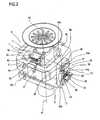
- Each device 3comprises a pedestal 4 connected to the bed 2, a rod 5 capable of movement relative to the pedestal 4 in the direction denoted D, and a head 6 carried by a top end of the rod 5.
- the rod 5 and pedestal 4are aligned on a first centre axis A1 extending substantially parallel to the predetermined direction D.
- Movement of the rod 5 relative to the pedestal 4is induced by means of components and methods familiar to a person skilled in the art, hence neither illustrated in the drawings nor described in the course of the present specification.
- the head 6supports a fixture mechanism 7 for anchoring the workpiece.
- the fixture mechanism 7is aligned on a second centre axis A2.
- the head 6comprises a fixed portion 8 associated rigidly with the rod 5, and a tilting element 9 interposed between the fixed portion 8 and the fixture mechanism 7.
- the tilting element 9appears substantially as a quadrangular ring and thus presents four sides 9a, 9b, 9c and 9d of which those lying opposite one another are disposed mutually parallel and those adjoining are disposed at right angles.
- the fixed portion 8comprises two cantilevered brackets 10 and 11 extending upward parallel one with another and with the direction denoted D; the two brackets 10 and 11 are diametrically opposed on either side of the first centre axis A1.
- the two brackets 10 and 11 of the fixed portion 8are furnished with respective first pivots 12.
- the tilting element 9is mounted freely via the sides denoted 9b and 9d to the first pivots 12 and capable thus of angular movement, relative to the fixed portion 8, about a first axis R1 of rotation coinciding with a common fulcrum axis on which the first pivots 12 are aligned.
- the fixture mechanism 7is mounted freely to these second pivots 13 and capable thus of angular movement relative to the tilting element 9 about a second axis R2 of rotation coinciding with a common fulcrum axis on which the selfsame second pivots 13 are aligned.
- the fixture mechanism 7comprises a central body 14 engaging with the second pivots 13, a spherically contoured lower portion 15, and a suction cup 16 designed to engage in direct contact with a workpiece of the type aforementioned (not illustrated).
- a suction duct 17serving to establish a fluid connection between the suction cup 16 and a source of negative pressure represented schematically in figure 4 as a block, denoted 18.
- the suction duct 17comprises a first leg 17a located in the fixture mechanism 7 and connecting with the suction cup 16, a second leg 17b located in the tilting element 9, extending in part through one of the second pivots 13 and thus coaxial with the second axis R2 of rotation, and a third leg 17c located in the fixed portion 8 of the head 6.
- the third leg 17c of the duct 17extends in part through one of the first pivots 12, coaxial with the first axis R1 of rotation, and in part through the bracket denoted 11.
- the negative pressure source 18, suction duct 17 and suction cup 16combine to establish means denoted 19 in their entirety, ensuring the adhesion of the fixture mechanism 7 to the workpiece (not illustrated).
- the device 3comprises a restraining element 20 by which the fixture mechanism 7 can be immobilized relative to the first and second axes R1 and R2 of rotation.
- the restraining element 20is carried slidably by the fixed portion 8 of the head 6 and comprises a hollow cylindrical portion 21 presenting a splayed rim 22 uppermost, a rod 23 coaxial with the first centre axis A1, to which the cylindrical portion 21 is secured with a screw 24, and a plate 25 keyed to a bottom end of the rod 23.
- a first annular chamber 26 located between the rod 23 and the fixed portion 8provides the housing for a coil spring 27 by which the selfsame rod 23 is biased in a direction denoted F1, parallel with the aforementioned direction D.
- a second annular chamber 28 located beneath the first annular chamber 26provides a housing for the plate 25.
- the fixed portion 8 of the head 6incorporates a gallery 29 through which a pressurized fluid is supplied to the second annular chamber 28.
- the pressurized fluidpreferably would be air, directed into the gallery 29 from a source shown schematically in figure 5 as a block denoted 30.
- the restraining element 20is capable of movement between a first position of engagement with the fixture mechanism 7 (as illustrated in figures 6 and 7 , where the head 6 is shown in an alternative embodiment denoted 6', which is not part of the present invention), in which the splayed rim 22 of the hollow cylindrical portion 21 is directed forcibly against the aforementioned spherically contoured portion 15, with the result that the fixture mechanism 7 is locked and prevented from pivoting about the first and second axes R1 and R2 of rotation, and a second position of disengagement (illustrated in figures 4 and 5 ) in which the splayed rim 22 is distanced from the spherically contoured portion 15 and the fixture mechanism 7 is free to pivot about the first and second axes R1 and R2 of rotation.
- the restraining element 20constitutes means 31 by which to immobilize the fixture mechanism 7 relative to the first and second axes R1 and R2 of rotation.
- the source 30 of pressurized fluidcombines with the gallery 29 and the plate 25 to establish means, denoted 32 in their entirety, by which the restraining element 20 is actuated.
- the bracket denoted 10carries two rocker levers 33 and 34, mounted concentrically with the first axis R1 of rotation, presenting respective lower arms 33a and 34a and upper arms 33b and 34b.
- each lever 33 and 34is anchored to one respective end of a coil spring denoted 35.
- a limit position of minimum distance between the two lower arms 33a and 34ais established by two stop elements 36 fixed to the bracket 10.
- each lever 33 and 34is placed so as to locate against a respective pin 37 projecting from the corresponding side 9b of the tilting element 9.
- Each pin 37occupies a relative clearance slot 38 of curved outline afforded by the bracket 10.
- the coil spring 35, rocker levers 33 and 34 and pins 37combine to provide the device 3 with first spring means 39 opposing the angular movement of the tilting element 9 about the first axis R1 of rotation.
- the purpose of the first spring means 39is to hold the tilting element 9 in a stable state of balance relative to the first axis R1 of rotation. In other words, when the tilting element 9 is not subject to the action of external forces, the first spring means 39 will ensure that the second axis R2 of rotation stays substantially orthogonal to the first centre axis A1 of the rod 5.
- the tilting element 9carries two levers 40 and 41 pivotable on a common fulcrum coinciding with the second axis R2 of rotation.
- the two levers 40 and 41are anchored each to one respective end of a coil spring 42, and positioned to locate against opposite corner edges of a fixed plate 43 cantilevered from the central body 14 of the fixture mechanism 7.
- the plate 43When in contact with the levers 40 and 41, the plate 43 establishes a limit position of minimum distance between the selfsame levers 40 and 41.
- the coil spring 42, levers 40 and 41 and plate 43combine thus to provide second spring means 44 opposing the angular movement of the fixture mechanism 7 about the second axis R2 of rotation.
- the purpose of the second spring means 44is to hold the fixture mechanism 7 in a stable state of balance relative to the second axis R2 of rotation. In other words, when the fixture mechanism 7 is not subject to the action of external forces, for example as when in contact with a workpiece, the second spring means 44 will ensure that the second centre axis A2 of the fixture mechanism 7 stays substantially orthogonal to the first axis R1 of rotation.
- the coil spring 27 occupying the first annular chamber 26provides third spring means 45 opposing the action of the actuating means 32.
- the device 3further comprises a presence sensor 46 such as will detect the shift of a plunger 47 mounted slidably and flexibly within the central body 14 of the fixture mechanism 7, and extending longitudinally in the direction denoted D.
- a top end 47a of the plunger 47emerges into the suction cup 16 and is positioned thus to engage in contact with a workpiece, so that the presence of the workpiece can be signalled to the sensor 46 by a sliding movement of the plunger.
- the sensor 46is connected to a monitoring and control unit substantially of conventional type, which is neither illustrated in the drawings nor described in the course of the specification.
- the sensor 46provides the device 3 with means 48 by which to detect the proximity of the fixture mechanism 7 to the workpiece (not illustrated).
- Figures 6 to 8illustrate a different embodiment of the head 6 according to the present invention.
- this head 6'also carries a fixture mechanism 7 for anchoring a workpiece.
- the fixture mechanism 7is aligned on a second centre axis A2.
- the head 6'further comprises a fixed portion 8 associated rigidly with the rod 5, and a tilting element 9 interposed between the fixed portion 8 and the fixture mechanism 7.
- the tilting element 9appears substantially as a quadrangular ring and thus presents four sides 9a, 9b, 9c and 9d of which those lying opposite one another are disposed mutually parallel and those adjoining are disposed at right angles. Each two adjoining sides 9a, 9b, 9c and 9d are interconnected by a respective curved segment.
- the fixed portion 8comprises two cantilevered brackets 10 and 11 extending upward parallel one with another and with the direction denoted D; the two brackets 10 and 11 are diametrically opposed on either side of the first centre axis A1.
- the two brackets 10 and 11 of the fixed portion 8are furnished with respective first pivots 12, of which one only is visible in the drawing.
- the tilting element 9is mounted freely via the sides denoted 9b and 9d to the first pivots 12 and capable thus of angular movement, relative to the fixed portion 8, about a first axis R1 of rotation coinciding with a common fulcrum axis on which the first pivots 12 are aligned.
- the fixture mechanism 7is mounted freely to these second pivots 13 and capable thus of angular movement relative to the tilting element 9 about a second axis R2 of rotation coinciding with a common fulcrum axis on which the selfsame second pivots 13 are aligned.
- the fixture mechanism 7comprises a central body 14 engaging with the second pivots 13, a spherically contoured lower portion 15, and a suction cup 16 designed to engage in direct contact with a workpiece (not illustrated).
- the head 6'also comprises a first or bottom flange 49, and a second or top flange 50 of cupped appearance.
- the bottom first flange 49is circular in shape, rigidly associated with the fixed portion 8 of the head 6' and aligned concentrically on the first centre axis A1.
- the top second flange 50likewise circular, is carried by the central body 14 of the fixture mechanism 7 and aligned concentrically on the second centre axis A2.
- the two endmost coils of the spring 51are seated against annular projections 52 and 53 afforded by respective inner faces 49a and 50a of the first flange 49 and the second flange 50.
- the coil spring 51can be shielded by a convoluted cylindrical boot of familiar type (not illustrated), connecting the two flanges 49 and 50 flexibly and ensuring optimum mobility of the one relative to the other while preventing dust or chips from penetrating and fouling the head 6'.
- the cupped second flange 50also presents a top outer face 50b of concave appearance, delimited by an annular rim 54 aligned concentrically on the second centre axis A2.
- the second flange 50With its concave face and annular rim 54, the second flange 50 thus provides a guard element 55 serving to protect the suction cup 16.
- the coil spring denoted 51serves to maintain the fixture mechanism 7 in a stable state of balance relative to the second axis R2 of rotation, and the tilting element 9 in a stable state of balance relative to the first axis R1 of rotation.
- the coil spring 51will ensure that the second centre axis A2 of the fixture mechanism 7 remains substantially in alignment with the first centre axis A1 of the rod 5.
- the device 3comprises a suction duct 17 establishing a fluid connection between the suction cup 16 and a source of negative pressure, represented schematically in figure 6 as a block denoted 18.
- the suction duct 17comprises a first leg 17a located in the fixture mechanism 7 and connecting with the suction cup 16, a second leg 17b located in the tilting element 9, extending in part through of the second pivots 13 and thus coaxial with the second axis R2 of rotation, and a third leg 17c connected with the negative pressure source 18.
- the negative pressure source 18, suction duct 17 and suction cup 16combine to establish means denoted 19 in their entirety, ensuring the adhesion of the fixture mechanism 7 to a workpiece (not illustrated).
- this second head 6'comprises a restraining element 20 by which the fixture mechanism 7 can be immobilized relative to the first and second axes R1 and R2 of rotation. Since the restraining element 20 of the second head 6' is substantially identical to that of the head 6 first described, reference can be made to the earlier part of the specification for a detailed description of the component parts.
- the device 3comprises a presence sensor 46, illustrated in figure 6 , such as will detect the shift of a plunger 47 extending longitudinally in the direction denoted D, mounted slidably within a cylindrical tube 56 and cushioned flexibly by a spring 57 seated in a housing afforded by the spherically contoured lower portion 15.
- a presence sensor 46illustrated in figure 6 , such as will detect the shift of a plunger 47 extending longitudinally in the direction denoted D, mounted slidably within a cylindrical tube 56 and cushioned flexibly by a spring 57 seated in a housing afforded by the spherically contoured lower portion 15.
- the tube 56 slidably housing the plunger 47is rigidly associated with the central body 14 and presents a top end 56a providing the device 3 with a fixed point of reference from which to calculate positioning distances, when securing the workpiece, and possibly machining distances thereafter.
- the central body 14houses a piston 58, slidable relative to the selfsame body 14 along the centre axis A2 of the fixture mechanism 7.
- the piston 58consists essentially in a hollow cylindrical body 58a, an internal web 58b affording a square hole (not illustrated) occupied slidably by the aforementioned cylindrical tube 56, and an annular yoke 59 consisting of two walls 59a and 59b, respectively upper and lower.
- the walls 59a and 59bare visible respectively in figure 6 and in figure 7 .
- the piston 58is connected rigidly to the suction cup 16 by means of a threaded sleeve 60.
- the internal web 58b of the piston 58is engaged from beneath by a compression spring 61 serving to bias the piston 58 away from the lower portion 15 of the fixture mechanism 7.
- the compression spring 61is coiled partially about a base portion of the tube 56.
- Numeral 62denotes a first annular air plenum located in a top part of the lower portion 15, at its connection with the central body 14, into which compressed air is directed through a duct 62a shown only fragmentarily in figures 6 and 7 .
- a second annular air plenum 63afforded in turn by the central body 14, is filled with compressed air from a relative duct not shown in the drawings.
- numeral 64denotes an air chamber located between the piston 58, the central body 14 and the two annular plenums 62 and 63, into which compressed air is directed from the two plenums 62 and 63 through respective openings, not illustrated, afforded by the selfsame plenums.
- the fluid connection between the first leg 17a of the duct and the suction cup 16occurs through the inside of the piston 58, and in particular exploiting the square outline of the hole, not illustrated, in the web 58b of the piston 58.
- the tube 56being of cylindrical geometry and therefore circular outline, its outer circumference is inscribed within the quadrangular perimeter of the square presented by the hole (not illustrated): thus, the difference between the area of the square and the area of the circle delimited by the circumference of the tube creates a passage that forms part of the suction duct.
- a workpiece of the type aforementioned(not illustrated) is positioned on the equipment 1 and the various support devices 3 are activated, in substantially familiar manner, with the rod 5 of each one being adjusted along the direction D to a predetermined height such as will allow a respective portion of the workpiece to be properly supported.
- the positioning stepsare carried out with the aid of the aforementioned presence sensor 46, adopting conventional procedures that are not described further.
- the suction cup 16For the suction cup 16 to establish a secure grip on the workpiece, it must be offered substantially parallel to the surface of the work at the point of contact. In other words, the second axis A2 of the fixture mechanism 7 must be set perpendicularly to the aforementioned surface of the work.
- the correct positioning in questionwill occur automatically when positive contact is made between the suction cup 16, or the cupped second flange 50, and the surface of the workpiece, but can also be expedited manually by an operator as and when appropriate.
- the suction duct 17is opened so as to connect the suction cup 16 to the source of negative pressure 18.
- the reference planecoincides substantially with the surface of the workpiece (not illustrated), and accordingly, the fact that both the suction cup 16 and the rim 54 of the cupped second flange 50 are positioned at the same height is instrumental, during operation, in ensuring that the area immediately around the suction cup 16 remains protected against the penetration of dust, chips and machining debris, and that the cup itself is prevented advantageously from becoming worn and damaged.
- the workpiececan be machined.
- the steps in questionare accomplished by charging the second plenum 63 with compressed air, which then passes through the aforementioned openings (not illustrated) and is directed onto the top wall 59a presented by the annular yoke 59 of the piston 58.
- each device 3is no longer subject to any external action, other than a possible corrective action of the two coil springs 35 and 42, in the case of the first head 6, or the one coil spring 51 in the case of the second head 6'.
- the springs 35, 42 and 51 in questionwill come into operation whenever the second centre axis A2 of the fixture mechanism 7 shifts away from a position of coaxial alignment with the first centre axis A1 of the rod 5.
- any angular movement of the tilting element 9 about the relative axis R1 of rotationwill cause one of the two pins 37 to engage with one of the upper arms 33b and 34b of the rocker levers 33 and 34, with the result that the lever 33 or 34 rotates about the axis R1.
- the one rocker lever 33pivots clockwise about the axis R1 of rotation, whilst the other lever 34 pivots anticlockwise.
- the tilting element 9is caused to pivot clockwise about its axis R1
- the pin 37 engaging the upper arm denoted 33bwill have produced a corresponding clockwise rotation of the lever 33, and correspondingly, the lower arm 33a of this same lever will have extended and loaded the coil spring 35.
- the spring denoted 42will cause the levers 40 and 41 to bring the fixture mechanism 7, after pivoting on the second axis R2, into a state of balance with the second centre axis A2 substantially orthogonal to the first axis R1 of rotation.
- the configuration of the fixture mechanism 7 as illustrated in figure 2is therefore one of stable balance, given that when shifted one way or the other, the component 7 will tend always to reassume this same configuration.
- the configuration of the fixture mechanism 7 in the case of the head 6' illustrated in figure 8is describable as one of instability, given that when the external forces are removed, the coil spring 51 will cause the component 7 to move away from this configuration and return to a condition in which the two axes A1 and A2 are substantially aligned.
- figures 4 and 5illustrate the restraining element 20 in the aforementioned second position of disengagement, that is to say with the fixture mechanism 7 free to pivot on the first and second axes R1 and R2 of rotation.
- the position of disengagementis brought about pneumatically, as the result of compressed air being directed into the second annular chamber 28 and acting on the plate 25.
- the restraining element 20To immobilize the fixture mechanism 7 in a given position, the restraining element 20 must be moved into the first position of engagement (illustrated in figures 6 and 7 ), with the splayed top rim 22 of the hollow cylindrical portion 21 directed forcibly against the spherically contoured portion 15.
- the restraining element 20is moved from the second position to the first position simply by shutting off the flow of compressed air into the annular chamber 28, or at any rate by restoring a level of pressure in the chamber 28 insufficient to oppose the mechanical force of the spring 27.
- the guard element 55which, being fashioned from a rigid material, serves both to protect the suction cup 16 from unintended impact with the workpiece, and to bolster the interface between the workpiece and the pivotable parts of the device, so that the desired position of engagement with the workpiece is achieved with greater speed and precision.
- the suction cup 16would be offered to the workpiece directly, and this could introduce a delay factor into the movements of pivotable parts due to the elastically deformable nature of the cup 16.
- any such drawbackis precluded by the adoption of a guard element 55 in the form of the cupped second flange 50.
- the second flange 50serves to protect the suction cup 16 both during the step of positioning the head 6' against the workpiece, and after the work has been secured, or more exactly, guarding initially against impact and rubbing contact that could degrade a deformable material with a high coefficient of friction, and thereafter, preventing exposure of the suction cup 16 to machining chips and dust.
- the effectiveness of movement obtainable with the device according to the inventionis advantageously greater than that of a conventional ball joint, and achieved without any risk of component parts being degraded by the penetration of machining debris, also without the need for fixture heads to undergo frequent and thorough cleaning operations.
Landscapes
- Engineering & Computer Science (AREA)
- Mechanical Engineering (AREA)
- Jigs For Machine Tools (AREA)
- Manipulator (AREA)
- Vehicle Body Suspensions (AREA)
- Paper (AREA)
- Automobile Manufacture Line, Endless Track Vehicle, Trailer (AREA)
Abstract
Description
- The present invention relates to a support device for securing workpieces.
- In particular, the invention relates to a device mounted on equipment designed to secure both curved and flat pieces of sheet material, typically body pressings or fuselage panels or the like, during the course of machining operations performed on these same pieces.
- In sectors such as the aerospace and shipbuilding industries, machining cycles need to be carried out on pieces very often of appreciable dimensions and of curved and irregular geometry, a fact that both complicates the handling of such items considerably and causes notable difficulty in making the work secure during machining operations.
- To optimize the positioning of these large items, installations typical of the prior art employ a rigid frame or gantry carrying a unit by which the work is machined. The workpiece is placed beneath the frame, and to achieve stable positioning, such installations comprise a plurality of columns, each equipped at its free top end with a support device, to which the parts for machining can be securely anchored; this ensures that machining distances are accurately maintained and that machining tools will encounter a suitably firm reaction force.
- The supporting columns are capable of vertical movement, so as to adapt to the dissimilar heights that different parts of the workpiece may occupy by reason of its curved geometry.
- Moreover, the curved or at all events irregular profile of the workpiece dictates also that the support devices fitted to the columns should be capable of adapting to the angle of inclination presented by the piece at the point of engagement with each device.
- Conventional support devices normally comprise an aspirating element, typically a suction cup, and a ball and socket structure to which the aspirating element is mounted.
- Patent
EP 69230 - During the positioning step, overpressure is generated in the hemispherical chamber of the aspirating element so that the workpiece is carried on an air cushion, and can be manoeuvred while floating substantially free of frictional contact.
- The spherical shell rests on a cup, likewise of essentially spherical geometry, and can be shifted through predetermined angles relative to this same cup so as to adapt to the angle of inclination of the workpiece being supported.
- Numerous other solutions exist for such support devices, comprising elements that appear spherical or in any event are positionable by means of a ball joint type mechanism.
- Other examples of support devices for securing workpieces having curved and irregular geometry can be met both in the document
EP-A-0596189 and in the documentDD272450A1 - The solutions in question have proved effective to a degree, but are not without drawbacks.
- A first drawback consists in the fact that chips and dust can easily be deposited on and penetrate the ball joints during the course of machining operations. This is a situation that can impede the movement of the elements making up the support devices and even cause them to seize, in extreme cases, with a self-evidently negative impact on the duration and precision of the machining operations that need to be carried out.
- To the end of avoiding the drawbacks in question, and ensuring that dust and machining debris will not affect the effectiveness of the ball joints, lengthy and thorough cleaning operations must be carried out between one machining cycle and the next, or even while machining is in progress.
- Another drawback connected with the use of ball joints in support devices of the type in question is that of the limited angle of manoeuvre afforded to the component parts of the joint, and therefore to the suction cup directly engaging the workpiece.
- With this in mind, patent
EP 507033 - Whilst the addition of an intermediate spherical shell represents a positive step, on the one hand, in that it provides the suction cup with increased freedom of angular movement, it serves on the other only to enlarge the areas of the joint exposed to the risk of penetration by machining debris, chips or dust as mentioned above.
- Accordingly, the object of the present invention is to provide a support device for securing workpieces that will be unaffected by the drawbacks mentioned above, and moreover will be practical and effective in use.
- The stated object is realized according to the present invention in a support device for securing workpieces, of which the characterizing features are as recited in
claim 1 and in any other claim directly or indirectly dependent onclaim 1. - The invention will now be described in detail, by way of example, with the aid of the accompanying drawings, in which:
figure 1 shows a portion of equipment comprising a plurality of support devices according to the present invention, illustrated in perspective from above;figure 2 shows a portion of a support device according to the present invention, illustrated in perspective from above;figure 3 shows the device offigure 2 from above, in a schematic plan view;figure 4 is a side view of the device infigure 3 , showing the section on IV-IV;figure 5 is a side view of the device infigure 3 , showing the section on V-V;figures 6 and7 are sectional side views showing an alternative embodiment(not forming part of the present invention) of the support device infigures 2 to 5 , illustrated in two different operating configurations;figure 8 shows the device offigures 6 and7 , illustrated in perspective from above and occupying a different configuration in space.- With reference to
figure 1 ,numeral 1 denotes a portion, in its entirety, of equipment on which to support workpieces (not illustrated) for machining. - Though not illustrated, the workpieces for which the
equipment 1 is ideally suited will be fashioned typically from metal or plastic sheet material. - The
equipment 1 includes abed 2 of substantially familiar embodiment, indicated fragmentarily and schematically infigure 1 , and a plurality ofdevices 3 by which the aforementioned workpieces (not illustrated) are engaged. - The
support devices 3 are capable of vertical movement one independently of another along a predetermined direction D, in order to adapt to the geometry of the workpieces in question, which can often present notably irregular shapes. - Each
device 3 comprises apedestal 4 connected to thebed 2, arod 5 capable of movement relative to thepedestal 4 in the direction denoted D, and ahead 6 carried by a top end of therod 5. - The
rod 5 andpedestal 4 are aligned on a first centre axis A1 extending substantially parallel to the predetermined direction D. - Movement of the
rod 5 relative to thepedestal 4 is induced by means of components and methods familiar to a person skilled in the art, hence neither illustrated in the drawings nor described in the course of the present specification. - Referring to
figure 2 , thehead 6 supports afixture mechanism 7 for anchoring the workpiece. - The
fixture mechanism 7 is aligned on a second centre axis A2. - The
head 6 comprises afixed portion 8 associated rigidly with therod 5, and a tiltingelement 9 interposed between thefixed portion 8 and thefixture mechanism 7. - The tilting
element 9 appears substantially as a quadrangular ring and thus presents foursides - The
fixed portion 8 comprises twocantilevered brackets brackets - As illustrated in
figure 4 , the twobrackets portion 8 are furnished with respectivefirst pivots 12. - The tilting
element 9 is mounted freely via the sides denoted 9b and 9d to thefirst pivots 12 and capable thus of angular movement, relative to thefixed portion 8, about a first axis R1 of rotation coinciding with a common fulcrum axis on which thefirst pivots 12 are aligned. - Referring to
figure 5 , it will be seen that the sides of the tiltingelement 9 denoted 9a and 9c are furnished with respectivesecond pivots 13. - The
fixture mechanism 7 is mounted freely to thesesecond pivots 13 and capable thus of angular movement relative to the tiltingelement 9 about a second axis R2 of rotation coinciding with a common fulcrum axis on which the selfsamesecond pivots 13 are aligned. - With reference to
figures 4 and5 , thefixture mechanism 7 comprises acentral body 14 engaging with thesecond pivots 13, a spherically contouredlower portion 15, and asuction cup 16 designed to engage in direct contact with a workpiece of the type aforementioned (not illustrated). - Also forming part of the
device 3 is asuction duct 17 serving to establish a fluid connection between thesuction cup 16 and a source of negative pressure represented schematically infigure 4 as a block, denoted 18. - The
suction duct 17 comprises afirst leg 17a located in thefixture mechanism 7 and connecting with thesuction cup 16, asecond leg 17b located in thetilting element 9, extending in part through one of thesecond pivots 13 and thus coaxial with the second axis R2 of rotation, and athird leg 17c located in thefixed portion 8 of thehead 6. Thethird leg 17c of theduct 17 extends in part through one of thefirst pivots 12, coaxial with the first axis R1 of rotation, and in part through the bracket denoted 11. - The
negative pressure source 18,suction duct 17 andsuction cup 16 combine to establish means denoted 19 in their entirety, ensuring the adhesion of thefixture mechanism 7 to the workpiece (not illustrated). - As discernible in
figures 4 and5 , thedevice 3 comprises arestraining element 20 by which thefixture mechanism 7 can be immobilized relative to the first and second axes R1 and R2 of rotation. Therestraining element 20 is carried slidably by thefixed portion 8 of thehead 6 and comprises a hollowcylindrical portion 21 presenting asplayed rim 22 uppermost, arod 23 coaxial with the first centre axis A1, to which thecylindrical portion 21 is secured with ascrew 24, and aplate 25 keyed to a bottom end of therod 23. - A first
annular chamber 26 located between therod 23 and thefixed portion 8 provides the housing for acoil spring 27 by which theselfsame rod 23 is biased in a direction denoted F1, parallel with the aforementioned direction D. - A second
annular chamber 28 located beneath the firstannular chamber 26 provides a housing for theplate 25. - Referring to
figure 5 , thefixed portion 8 of thehead 6 incorporates agallery 29 through which a pressurized fluid is supplied to the secondannular chamber 28. - The pressurized fluid preferably would be air, directed into the
gallery 29 from a source shown schematically infigure 5 as a block denoted 30. - The
restraining element 20 is capable of movement between a first position of engagement with the fixture mechanism 7 (as illustrated infigures 6 and7 , where thehead 6 is shown in an alternative embodiment denoted 6',which is not part of the present invention), in which thesplayed rim 22 of the hollowcylindrical portion 21 is directed forcibly against the aforementioned spherically contouredportion 15, with the result that thefixture mechanism 7 is locked and prevented from pivoting about the first and second axes R1 and R2 of rotation, and a second position of disengagement (illustrated infigures 4 and5 ) in which thesplayed rim 22 is distanced from the spherically contouredportion 15 and thefixture mechanism 7 is free to pivot about the first and second axes R1 and R2 of rotation. - The
restraining element 20 constitutes means 31 by which to immobilize thefixture mechanism 7 relative to the first and second axes R1 and R2 of rotation. - The
source 30 of pressurized fluid combines with thegallery 29 and theplate 25 to establish means, denoted 32 in their entirety, by which therestraining element 20 is actuated. - As illustrated in
figures 2 and4 , the bracket denoted 10 carries two rocker levers 33 and 34, mounted concentrically with the first axis R1 of rotation, presenting respectivelower arms upper arms - The
lower arm lever - A limit position of minimum distance between the two
lower arms stop elements 36 fixed to thebracket 10. - The
upper arm lever respective pin 37 projecting from thecorresponding side 9b of thetilting element 9. - Each
pin 37 occupies arelative clearance slot 38 of curved outline afforded by thebracket 10. - The
coil spring 35, rocker levers 33 and 34 and pins 37 combine to provide thedevice 3 with first spring means 39 opposing the angular movement of thetilting element 9 about the first axis R1 of rotation. - The purpose of the first spring means 39 is to hold the
tilting element 9 in a stable state of balance relative to the first axis R1 of rotation. In other words, when the tiltingelement 9 is not subject to the action of external forces, the first spring means 39 will ensure that the second axis R2 of rotation stays substantially orthogonal to the first centre axis A1 of therod 5. - As illustrated in
figures 2 and5 , the tiltingelement 9 carries twolevers - The two
levers coil spring 42, and positioned to locate against opposite corner edges of a fixedplate 43 cantilevered from thecentral body 14 of thefixture mechanism 7. - When in contact with the
levers plate 43 establishes a limit position of minimum distance between theselfsame levers - The
coil spring 42, levers 40 and 41 andplate 43 combine thus to provide second spring means 44 opposing the angular movement of thefixture mechanism 7 about the second axis R2 of rotation. - The purpose of the second spring means 44 is to hold the
fixture mechanism 7 in a stable state of balance relative to the second axis R2 of rotation. In other words, when thefixture mechanism 7 is not subject to the action of external forces, for example as when in contact with a workpiece, the second spring means 44 will ensure that the second centre axis A2 of thefixture mechanism 7 stays substantially orthogonal to the first axis R1 of rotation. - The
coil spring 27 occupying the firstannular chamber 26 provides third spring means 45 opposing the action of the actuating means 32. - With reference to
figure 5 , thedevice 3 further comprises apresence sensor 46 such as will detect the shift of aplunger 47 mounted slidably and flexibly within thecentral body 14 of thefixture mechanism 7, and extending longitudinally in the direction denoted D. - A
top end 47a of theplunger 47 emerges into thesuction cup 16 and is positioned thus to engage in contact with a workpiece, so that the presence of the workpiece can be signalled to thesensor 46 by a sliding movement of the plunger. - The
sensor 46 is connected to a monitoring and control unit substantially of conventional type, which is neither illustrated in the drawings nor described in the course of the specification. - In combination with the
plunger 47, thesensor 46 provides thedevice 3 withmeans 48 by which to detect the proximity of thefixture mechanism 7 to the workpiece (not illustrated). Figures 6 to 8 illustrate a different embodiment of thehead 6 according to the present invention.- Whilst the head of
figures 6 ,7 and8 is denoted by the numeral 6', in its entirety, the component parts corresponding and similar to those already described above are denoted infigures 6 ,7 and8 using the same numbers as infigures 2 to 5 . - Like the
head 6 first described, this head 6' also carries afixture mechanism 7 for anchoring a workpiece. - The
fixture mechanism 7 is aligned on a second centre axis A2. - The head 6' further comprises a fixed
portion 8 associated rigidly with therod 5, and atilting element 9 interposed between the fixedportion 8 and thefixture mechanism 7. - In the example of
figure 8 , the tiltingelement 9 appears substantially as a quadrangular ring and thus presents foursides sides - The fixed
portion 8 comprises two cantileveredbrackets brackets - As discernible from
figure 8 , the twobrackets portion 8 are furnished with respectivefirst pivots 12, of which one only is visible in the drawing. - The tilting
element 9 is mounted freely via the sides denoted 9b and 9d to thefirst pivots 12 and capable thus of angular movement, relative to the fixedportion 8, about a first axis R1 of rotation coinciding with a common fulcrum axis on which thefirst pivots 12 are aligned. - Referring to
figure 6 , it will be seen that the sides of thetilting element 9 denoted 9a and 9c are furnished with respective second pivots 13. - The
fixture mechanism 7 is mounted freely to thesesecond pivots 13 and capable thus of angular movement relative to thetilting element 9 about a second axis R2 of rotation coinciding with a common fulcrum axis on which the selfsamesecond pivots 13 are aligned. Thefixture mechanism 7 comprises acentral body 14 engaging with thesecond pivots 13, a spherically contouredlower portion 15, and asuction cup 16 designed to engage in direct contact with a workpiece (not illustrated). - As illustrated in
figures 6 and7 , the head 6' also comprises a first orbottom flange 49, and a second ortop flange 50 of cupped appearance. - The bottom
first flange 49 is circular in shape, rigidly associated with the fixedportion 8 of the head 6' and aligned concentrically on the first centre axis A1. - The top
second flange 50, likewise circular, is carried by thecentral body 14 of thefixture mechanism 7 and aligned concentrically on the second centre axis A2. - Interposed between the two
flanges - The two endmost coils of the
spring 51 are seated againstannular projections inner faces first flange 49 and thesecond flange 50. - To advantage, the
coil spring 51 can be shielded by a convoluted cylindrical boot of familiar type (not illustrated), connecting the twoflanges - The cupped
second flange 50 also presents a topouter face 50b of concave appearance, delimited by anannular rim 54 aligned concentrically on the second centre axis A2. - With its concave face and
annular rim 54, thesecond flange 50 thus provides aguard element 55 serving to protect thesuction cup 16. - In like manner to the first and second spring means 39 and 44 of the
head 6 described previously, the coil spring denoted 51 serves to maintain thefixture mechanism 7 in a stable state of balance relative to the second axis R2 of rotation, and thetilting element 9 in a stable state of balance relative to the first axis R1 of rotation. In other words, when thefixture mechanism 7 and thetilting element 9 are not subject to the action of external forces, such as those generated by contact with a workpiece, thecoil spring 51 will ensure that the second centre axis A2 of thefixture mechanism 7 remains substantially in alignment with the first centre axis A1 of therod 5. - Likewise in this second embodiment, the
device 3 comprises asuction duct 17 establishing a fluid connection between thesuction cup 16 and a source of negative pressure, represented schematically infigure 6 as a block denoted 18. - The
suction duct 17 comprises afirst leg 17a located in thefixture mechanism 7 and connecting with thesuction cup 16, asecond leg 17b located in thetilting element 9, extending in part through of thesecond pivots 13 and thus coaxial with the second axis R2 of rotation, and athird leg 17c connected with thenegative pressure source 18. - The
negative pressure source 18,suction duct 17 andsuction cup 16 combine to establish means denoted 19 in their entirety, ensuring the adhesion of thefixture mechanism 7 to a workpiece (not illustrated). - Similarly to the
head 6 first described, this second head 6' comprises a restrainingelement 20 by which thefixture mechanism 7 can be immobilized relative to the first and second axes R1 and R2 of rotation. Since the restrainingelement 20 of the second head 6' is substantially identical to that of thehead 6 first described, reference can be made to the earlier part of the specification for a detailed description of the component parts. - The
device 3 comprises apresence sensor 46, illustrated infigure 6 , such as will detect the shift of aplunger 47 extending longitudinally in the direction denoted D, mounted slidably within acylindrical tube 56 and cushioned flexibly by aspring 57 seated in a housing afforded by the spherically contouredlower portion 15. - The
tube 56 slidably housing theplunger 47 is rigidly associated with thecentral body 14 and presents atop end 56a providing thedevice 3 with a fixed point of reference from which to calculate positioning distances, when securing the workpiece, and possibly machining distances thereafter. - As concerning the operation of the
plunger 47, reference can be made to the foregoing description of thehead 6 illustrated infigures 2 to 5 . - The
central body 14 houses apiston 58, slidable relative to theselfsame body 14 along the centre axis A2 of thefixture mechanism 7. - The
piston 58 consists essentially in a hollowcylindrical body 58a, aninternal web 58b affording a square hole (not illustrated) occupied slidably by the aforementionedcylindrical tube 56, and anannular yoke 59 consisting of twowalls walls figure 6 and infigure 7 . - The
piston 58 is connected rigidly to thesuction cup 16 by means of a threadedsleeve 60. - The
internal web 58b of thepiston 58 is engaged from beneath by acompression spring 61 serving to bias thepiston 58 away from thelower portion 15 of thefixture mechanism 7. - The
compression spring 61 is coiled partially about a base portion of thetube 56. Numeral 62 denotes a first annular air plenum located in a top part of thelower portion 15, at its connection with thecentral body 14, into which compressed air is directed through aduct 62a shown only fragmentarily infigures 6 and7 .- A second
annular air plenum 63, afforded in turn by thecentral body 14, is filled with compressed air from a relative duct not shown in the drawings. - Still in
figures 6 and7 , numeral 64 denotes an air chamber located between thepiston 58, thecentral body 14 and the twoannular plenums plenums - Referring again to the
suction duct 17, the fluid connection between thefirst leg 17a of the duct and thesuction cup 16 occurs through the inside of thepiston 58, and in particular exploiting the square outline of the hole, not illustrated, in theweb 58b of thepiston 58. - In other words, the
tube 56 being of cylindrical geometry and therefore circular outline, its outer circumference is inscribed within the quadrangular perimeter of the square presented by the hole (not illustrated): thus, the difference between the area of the square and the area of the circle delimited by the circumference of the tube creates a passage that forms part of the suction duct. - In operation, referring to
figure 1 , a workpiece of the type aforementioned (not illustrated) is positioned on theequipment 1 and thevarious support devices 3 are activated, in substantially familiar manner, with therod 5 of each one being adjusted along the direction D to a predetermined height such as will allow a respective portion of the workpiece to be properly supported. - The steps involved in positioning the
devices 3, as outlined previously, are substantially familiar and will not therefore be described further in any significant detail. - Advantageously, the positioning steps are carried out with the aid of the
aforementioned presence sensor 46, adopting conventional procedures that are not described further. - For the
suction cup 16 to establish a secure grip on the workpiece, it must be offered substantially parallel to the surface of the work at the point of contact. In other words, the second axis A2 of thefixture mechanism 7 must be set perpendicularly to the aforementioned surface of the work. - Accordingly, correct positioning of the
suction cup 16 and therefore of thefixture mechanism 7 is obtained by causing the selfsame component to pivot on the second axis R2 of rotation and causing thetilting element 9 to pivot on the first axis R1 of rotation. - The correct positioning in question will occur automatically when positive contact is made between the
suction cup 16, or the cuppedsecond flange 50, and the surface of the workpiece, but can also be expedited manually by an operator as and when appropriate. - Once the requisite positioning of the workpiece and the
fixture mechanism 7 one relative to another has been achieved, thesuction duct 17 is opened so as to connect thesuction cup 16 to the source ofnegative pressure 18. - The depression now created in the space between the
suction cup 16 and the surface of the workpiece will cause thefixture mechanism 7 to lock onto the workpiece, in conventional manner. - With reference to the head denoted 6' and to the illustration of
figure 7 , correct positioning of the head 6' is followed by the step of feeding compressed air into thefirst air plenum 62, from which the air will then be directed by way of the aforementioned openings (not illustrated), onto thebottom wall 59b presented by theannular yoke 59 of thepiston 58. - The force created by the action of compressed air on the
wall 59b combines with the mechanical force of thecompression spring 61 to lift thepiston 58 and the rigidly coupledsuction cup 16, producing the configuration offigure 7 , that is to say with thesuction cup 16 offered in full frontal contact to the workpiece (not illustrated). - With this upward movement of the
suction cup 16 on the line of the second centre axis A2, the topsecond flange 50 is left free to translate upward a short distance, displaced by the action of thecoil spring 51. - This translational movement enables the
annular rim 54 of the topsecond flange 50 to reach the plane of reference established by thetop end 56a of thetube 56. In other words, when thesuction cup 16 is raised and no longer retaining thesecond flange 50 in contact with thecentral body 14, theflange 50 is thrust substantially into contact with the surface of the work by thecoil spring 51. - As illustrated in
figure 7 , the reference plane coincides substantially with the surface of the workpiece (not illustrated), and accordingly, the fact that both thesuction cup 16 and therim 54 of the cuppedsecond flange 50 are positioned at the same height is instrumental, during operation, in ensuring that the area immediately around thesuction cup 16 remains protected against the penetration of dust, chips and machining debris, and that the cup itself is prevented advantageously from becoming worn and damaged. - Once all of the
devices 3 needed to secure the workpiece are in the active condition described above, the workpiece can be machined. - When machining operations have been completed, a pressure level at least equal to atmospheric will be re-established at the
suction cup 16, whereupon thefixture mechanisms 7 can be detached from the surface of the workpiece and the workpiece removed from theequipment 1. - In the case of the head 6' shown in
figure 6 , the steps in question are accomplished by charging thesecond plenum 63 with compressed air, which then passes through the aforementioned openings (not illustrated) and is directed onto thetop wall 59a presented by theannular yoke 59 of thepiston 58. - The force generated by pneumatic pressure on the
wall 59a overcomes the force of thespring 61, lowering thepiston 58 and the rigidly coupledsuction cup 16 to bring about the configuration illustrated infigure 6 , that is to say with thesuction cup 16 registering against the topouter face 50b of thesecond flange 50 and theflange 50 itself located against thecentral body 14. - Once the workpiece has been released, the
fixture mechanism 7 of eachdevice 3 is no longer subject to any external action, other than a possible corrective action of the twocoil springs first head 6, or the onecoil spring 51 in the case of the second head 6'. - The
springs fixture mechanism 7 shifts away from a position of coaxial alignment with the first centre axis A1 of therod 5. - Referring to
figure 2 , any angular movement of thetilting element 9 about the relative axis R1 of rotation will cause one of the twopins 37 to engage with one of theupper arms lever figure 3 , the onerocker lever 33 pivots clockwise about the axis R1 of rotation, whilst theother lever 34 pivots anticlockwise. - If, for example, the tilting
element 9 is caused to pivot clockwise about its axis R1, thepin 37 engaging the upper arm denoted 33b will have produced a corresponding clockwise rotation of thelever 33, and correspondingly, thelower arm 33a of this same lever will have extended and loaded thecoil spring 35. - When the force inducing angular movement of the
tilting element 9 has been removed, the reaction force of the loadedspring 35, tensioned by therocker lever 33 and thepin 37, will duly return thetilting element 9 to a state of balance with the second axis R2 of rotation substantially orthogonal to the first centre axis A1. - In like manner to the coil spring denoted 35, the spring denoted 42 will cause the
levers fixture mechanism 7, after pivoting on the second axis R2, into a state of balance with the second centre axis A2 substantially orthogonal to the first axis R1 of rotation. - The configuration of the
fixture mechanism 7 as illustrated infigure 2 is therefore one of stable balance, given that when shifted one way or the other, thecomponent 7 will tend always to reassume this same configuration. - Conversely, the configuration of the
fixture mechanism 7 in the case of the head 6' illustrated infigure 8 , assuming there are external forces tending to maintain the component in the position depicted, is describable as one of instability, given that when the external forces are removed, thecoil spring 51 will cause thecomponent 7 to move away from this configuration and return to a condition in which the two axes A1 and A2 are substantially aligned. - The movements of the
fixture mechanism 7 relative to the two axes R1 and R2 of rotation have been described thus far without reference to the action of the immobilizing means 31, now to be described. - To reiterate,
figures 4 and5 illustrate the restrainingelement 20 in the aforementioned second position of disengagement, that is to say with thefixture mechanism 7 free to pivot on the first and second axes R1 and R2 of rotation. - The position of disengagement is brought about pneumatically, as the result of compressed air being directed into the second
annular chamber 28 and acting on theplate 25. - In other words, the pressure of the air impinging on the top surface of the
plate 25 produces a force acting in the direction of the arrow denoted F2 and able to overcome the force of thecoil spring 27 acting in the direction of the arrow denoted F1. - To immobilize the
fixture mechanism 7 in a given position, the restrainingelement 20 must be moved into the first position of engagement (illustrated infigures 6 and7 ), with the splayedtop rim 22 of the hollowcylindrical portion 21 directed forcibly against the spherically contouredportion 15. The restrainingelement 20 is moved from the second position to the first position simply by shutting off the flow of compressed air into theannular chamber 28, or at any rate by restoring a level of pressure in thechamber 28 insufficient to oppose the mechanical force of thespring 27. - To advantage, accordingly, an unexpected loss of pneumatic pressure to the
head 6 or 6' caused by an equipment breakdown or malfunction will not result in a displacement of thefixture mechanism 7, since the position of the component is maintained by the force of thecoil spring 27, with compressed air used only to disengage the restrainingelement 20. - As regards the positioning of the device relative to the workpiece, in the case of the alternative embodiment of the head 6' according to the present invention, this is facilitated by the inclusion of the
guard element 55 which, being fashioned from a rigid material, serves both to protect thesuction cup 16 from unintended impact with the workpiece, and to bolster the interface between the workpiece and the pivotable parts of the device, so that the desired position of engagement with the workpiece is achieved with greater speed and precision. - Without the
guard element 55, in practice, thesuction cup 16 would be offered to the workpiece directly, and this could introduce a delay factor into the movements of pivotable parts due to the elastically deformable nature of thecup 16. - Advantageously, any such drawback is precluded by the adoption of a
guard element 55 in the form of the cuppedsecond flange 50. - Thus, the
second flange 50 serves to protect thesuction cup 16 both during the step of positioning the head 6' against the workpiece, and after the work has been secured, or more exactly, guarding initially against impact and rubbing contact that could degrade a deformable material with a high coefficient of friction, and thereafter, preventing exposure of thesuction cup 16 to machining chips and dust. - The effectiveness of movement obtainable with the device according to the invention is advantageously greater than that of a conventional ball joint, and achieved without any risk of component parts being degraded by the penetration of machining debris, also without the need for fixture heads to undergo frequent and thorough cleaning operations.
Claims (5)
- A support device for securing workpieces, capable of movement vertically in a predetermined direction (D) and adaptable thus to the shape of a workpiece, comprising:- a rod (5) aligned on a first centre axis (A1) extending parallel to the predetermined direction (D);- a head (6) attached to a top end of the rod (5), incorporating a fixture mechanism (7) aligned on a second centre axis (A2) and serving to anchor the workpiece,the fixture mechanism (7) being capable of angular movement relative to the rod (5) about first and second axes (R1, R2) of rotation, during which one of the first and second axes (R1, R2) of rotation remains orthogonal to the first centre axis (A1) of the rod (5) and the remaining first or second axis (R1, R2) of rotation remains orthogonal to the second centre axis (A2) of the fixture mechanism (7), the head (6) comprising a fixed portion (8) rigidly associated with the rod (5), and a tilting element (9) interposed between the fixed portion (8) of the head (6) and the fixture mechanism (7), the tilting element (9) being mounted pivotably to the fixed portion (8) of the head (6) and capable thus of angular movement about the first axis (R1) of rotation, the device further comprisingfirst spring means (39) opposing the angular movement of the tilting element (9) about the first axis (R1) of rotationand second spring means (44) opposing the angular movement of the tilting element (9) about the second axis (R2) of rotation; characterizing in that saidfirst spring means (39) comprises two rocker levers (33, 34), carried by a bracket (10) of the fixed portion (8) and mounted concentrically with the first axis (R1) of rotation, presenting respective lower arms (33a, 34a) and upper arms (33b, 34b); a coil spring (35) having ends anchored respectively to the lower arm (33a, 34a) of each lever (33, 34); the upper arm (33b, 34b) of each lever (33, 34) being placed so as to locate against a respective pin (37) projecting from a corresponding side (9b) of the tilting element (9).
- A device according to clam 1, that said second spring means (44) comprises two levers (40,41) carried by the tilting element (9) and pivotable on a common fulcrum coinciding to the second axis (R2) of rotation; a coil spring (42) having ends anchored respectively to each lever (33, 34) and positioned to locate against opposite corner edges of a fixed pilate (43) cantilevered from a central body (14) of the fixture element (7).
- A device according to claim 1, wherein the first and second axes (R1, R2) of rotation are mutually orthogonal.
- A device according to claim 1, wherein the fixture mechanism (7) is mounted pivotably to the tilting element (9) and capable thus of angular movement about the second axis (R2) of rotation.
- Equipment for supporting workpieces, consisting in particular of sheet metal or plastic material,characterized in that it comprises a plurality of support devices (3) as in claims 1 to 4.
Applications Claiming Priority (1)
| Application Number | Priority Date | Filing Date | Title |
|---|---|---|---|
| IT000376AITBO20050376A1 (en) | 2005-05-31 | 2005-05-31 | SUPPORT DEVICE FOR COMMITTING OEZZI IN PRODUCTION |
Publications (3)
| Publication Number | Publication Date |
|---|---|
| EP1728594A2 EP1728594A2 (en) | 2006-12-06 |
| EP1728594A3 EP1728594A3 (en) | 2008-08-06 |
| EP1728594B1true EP1728594B1 (en) | 2011-11-09 |
Family
ID=36847745
Family Applications (1)
| Application Number | Title | Priority Date | Filing Date |
|---|---|---|---|
| EP06114676ANot-in-forceEP1728594B1 (en) | 2005-05-31 | 2006-05-30 | A support device for securing workpieces |
Country Status (6)
| Country | Link |
|---|---|
| US (1) | US7918440B2 (en) |
| EP (1) | EP1728594B1 (en) |
| CN (1) | CN200967141Y (en) |
| AT (1) | ATE532608T1 (en) |
| ES (1) | ES2376634T3 (en) |
| IT (1) | ITBO20050376A1 (en) |
Cited By (1)
| Publication number | Priority date | Publication date | Assignee | Title |
|---|---|---|---|---|
| CN110291299A (en)* | 2016-11-16 | 2019-09-27 | 捷普有限公司 | Equipment, system and method for component or the air-supported platform of device |
Families Citing this family (41)
| Publication number | Priority date | Publication date | Assignee | Title |
|---|---|---|---|---|
| SG136008A1 (en)* | 2006-03-29 | 2007-10-29 | Jetsis Int Pte Ltd | Platform and method for supporting a workpiece to be cut from sheet material |
| DE102006032185B4 (en)* | 2006-07-12 | 2010-06-10 | Schott Ag | Holding system for fixing a substrate |
| DE102007037338A1 (en)* | 2007-08-08 | 2009-02-19 | Festool Gmbh | Workpiece holder with touch valve for a vacuum holding device |
| ITBS20080028A1 (en)* | 2008-02-11 | 2009-08-12 | Cms Spa | ADJUSTABLE SUCTION CUP, PARTICULARLY FOR BOXES FOR WORKING MACHINES |
| ES2357916T5 (en)* | 2008-02-25 | 2018-02-22 | Satisloh Ag | Locking part for maintaining an optical workpiece, in particular a lens for glasses, for processing, and method of manufacturing glasses for glasses according to a prescription |
| DE112009000465T5 (en)* | 2008-02-29 | 2011-02-24 | Thk Co., Ltd. | Turntable device, which is provided with a cooling structure, and pivot bearing, which is provided with a cooling structure |
| DE102008020215A1 (en)* | 2008-04-22 | 2009-10-29 | Junker & Partner Gmbh | Workpiece i.e. sheet metal part, mounting device for vehicle body, has connecting mechanisms fixed at carrier column, and connecting element adjusted by adjustment of deviation of holders from desired position |
| US9214372B2 (en)* | 2008-08-28 | 2015-12-15 | Tokyo Ohka Kogyo Co., Ltd. | Substrate processing system, carrying device and coating device |
| US8919756B2 (en)* | 2008-08-28 | 2014-12-30 | Tokyo Ohka Kogyo Co., Ltd. | Substrate processing system, carrying device, and coating device |
| KR101029450B1 (en)* | 2009-06-01 | 2011-04-14 | 한국항공우주산업 주식회사 | Aircraft Part Holding Fixture |
| WO2011009135A2 (en)* | 2009-07-17 | 2011-01-20 | Samac Robert A | Automated, adjustable, machine-tool work-piece-mounting apparatus |
| CN102549511B (en)* | 2009-08-06 | 2014-12-17 | 美国派尔(PaR)系统有限公司 | Flexible Fixtures |
| IT1400479B1 (en) | 2010-06-03 | 2013-06-11 | Zoppi | BENCH AND METHOD OF SUPPORT AND PROCESSING OF COMPLEX GEOMETRY |
| JP5625851B2 (en)* | 2010-12-10 | 2014-11-19 | 株式会社ジェイテクト | Power transmission chain pin assembly jig |
| CN102554823A (en)* | 2011-12-13 | 2012-07-11 | 苏州工业园区高登威科技有限公司 | Fixing device for mounting bush on circular hole of chassis of automobile transmission |
| CN102528693B (en)* | 2012-02-18 | 2014-02-19 | 营口三兴建业彩钢设备制造有限公司 | Suction cup flexible clamping tooling |
| DE102012209320A1 (en)* | 2012-06-01 | 2013-12-05 | Airbus Operations Gmbh | Method and storage device for storing and aligning a component |
| CN102886699B (en)* | 2012-10-29 | 2014-11-05 | 江苏科技大学 | Supporting device and supporting method for machining propeller blade |
| DE102012224280A1 (en)* | 2012-12-21 | 2014-06-26 | J. Schmalz Gmbh | jig |
| DE102013201765B4 (en)* | 2013-02-04 | 2019-02-07 | J. Schmalz Gmbh | Clamping device with lifting cylinders |
| CN103481089A (en)* | 2013-07-12 | 2014-01-01 | 沈阳航空航天大学 | Flexible clamping device for spatial curved surface thin-walled part |
| US9415520B2 (en)* | 2014-08-11 | 2016-08-16 | Swivel-Link, LLC | Swivel link for mounting end of arm tooling |
| DE102014216638B4 (en)* | 2014-08-21 | 2016-08-11 | J. Schmalz Gmbh | Clamping device with locking coupling and integrated suction channel for fixing a workpiece |
| CN104409389B (en)* | 2014-11-07 | 2017-10-27 | 合肥京东方光电科技有限公司 | A kind of board |
| JP6411985B2 (en)* | 2015-11-04 | 2018-10-24 | ファナック株式会社 | Rotating shaft support device with adjusting mechanism |
| US9833865B2 (en)* | 2015-12-02 | 2017-12-05 | The Boeing Company | Reconfigurable fixturing system and method |
| CN105855947A (en)* | 2016-06-01 | 2016-08-17 | 昆山科森科技股份有限公司 | Abnormal-shaped part fixing jig |
| CN107052859A (en)* | 2017-03-22 | 2017-08-18 | 江苏汤臣新材料科技有限公司 | A kind of ball-type lucite body machines frock |
| US10814459B2 (en)* | 2018-02-09 | 2020-10-27 | The Boeing Company | Apparatus and method for holding a workpiece |
| WO2019199718A1 (en) | 2018-04-12 | 2019-10-17 | Advanced Machine Works, LLC | Static flexible tooling system |
| US10520933B2 (en)* | 2018-04-13 | 2019-12-31 | The Boeing Company | System and method for removing a workpiece from a manufacturing fixture |
| CN110672885B (en)* | 2019-10-12 | 2021-06-29 | 绵阳瑞联电子机械技术有限公司 | Small positioning fixture device operated by single hand |
| CN110883718B (en)* | 2019-12-11 | 2021-05-28 | 成都工贸职业技术学院 | Vacuum adsorption clamp for sheet metal part |
| CN111515883B (en)* | 2020-05-28 | 2025-04-04 | 华中科技大学 | A support and positioning device for manufacturing curved plate |
| CN111761530B (en)* | 2020-07-08 | 2021-12-21 | 成都工贸职业技术学院 | Flexible adsorption combined clamp for curved surface part |
| CN116648327A (en)* | 2020-11-25 | 2023-08-25 | 泰普爱复合材料股份有限公司 | Universal support member for wind turbine blades |
| FR3123408B1 (en)* | 2021-05-27 | 2023-05-05 | Psa Automobiles Sa | Extended part support device of complex shape |
| CN113305603B (en)* | 2021-06-25 | 2022-03-25 | 天衍医疗器材有限公司 | Anti-deformation stress release clamping device |
| IT202100018461A1 (en)* | 2021-07-13 | 2023-01-13 | Working Process S R L | WORKING CENTER EQUIPPED WITH A WAREHOUSE OF WORKPIECE HOLDING EQUIPMENT AND MOBILE BARS FOR THE HANDLING AND/OR CONFIGURATION OF SUCH WORKPIECE HOLDING EQUIPMENT |
| CN114310004B (en)* | 2021-12-02 | 2024-02-06 | 佛山市盈美佳服装材料有限公司 | Irregular material fixing structure for laser marking machine |
| CN116330198A (en)* | 2023-03-21 | 2023-06-27 | 大连理工大学 | Method and structure for coaxial and parallel assembly of flexible piece and unidirectional force sensor |
Family Cites Families (17)
| Publication number | Priority date | Publication date | Assignee | Title |
|---|---|---|---|---|
| US3134208A (en)* | 1962-01-08 | 1964-05-26 | Clyde S Mccain | Lens holding device |
| DE3126720C2 (en)* | 1981-07-07 | 1987-04-02 | Messerschmitt-Bölkow-Blohm GmbH, 8012 Ottobrunn | Method for clamping workpieces and device for carrying out the method |
| DD272450A1 (en)* | 1988-05-26 | 1989-10-11 | Elektroprojekt Anlagenbau Veb | PNEUMATIC SUCTION GRIPPERS ACCORDING TO THE VENTURE PRINCIPLE |
| US5900870A (en)* | 1989-06-30 | 1999-05-04 | Massachusetts Institute Of Technology | Object-oriented computer user interface |
| DE4017983A1 (en)* | 1990-06-05 | 1991-12-12 | Airbus Gmbh | DEVICE FOR SETTING UP AND CLAMPING WORKPIECES |
| US5465946A (en)* | 1990-12-27 | 1995-11-14 | Smith; Dresden G. | Positioning fixture for welding operations having a lockable ball joint |
| EP0507033B1 (en) | 1991-04-05 | 1995-02-01 | Manuel Torres Martinez | Machine tool installation for supporting and machining workpieces |
| US5364083A (en)* | 1992-07-15 | 1994-11-15 | The Boeing Company | Universal holding fixture end effector |
| EP0596189A1 (en)* | 1992-11-06 | 1994-05-11 | GFM Gesellschaft für Fertigungstechnik und Maschinenbau Aktiengesellschaft | Reduced-pressure gripper for supporting and clamping workpieces |
| US5427363A (en)* | 1993-06-14 | 1995-06-27 | Cna Manufacturing Systems, Inc. | End effector |
| US5590870A (en)* | 1995-06-02 | 1997-01-07 | Advanced Machine & Engineering Co. | Universal holding system for a contoured workpiece |
| US5544968A (en)* | 1995-06-02 | 1996-08-13 | Advanced Machine & Engineering Co. | Lockable ball joint apparatus |
| US5833358A (en)* | 1995-11-21 | 1998-11-10 | Aci The Display People | Extruded track lighting system |
| US5738344A (en)* | 1996-04-01 | 1998-04-14 | Hagman; Erland | Ergonomic workpiece positioner |
| AU4665697A (en)* | 1996-10-07 | 1998-05-05 | Steven M. Moilanen | Modular stamped parts transfer gripper |
| US6012711A (en)* | 1997-12-10 | 2000-01-11 | International Business Machines Corporation | Alignment device for establishing a coplanar relationship between first and second surfaces |
| FR2804892B1 (en)* | 2000-02-11 | 2002-04-26 | Aerospatiale Matra Airbus | ADJUSTABLE GRIP MEMBER FOR THE TRANSPORT OR MACHINING OF ANY SHAPED PART |
- 2005
- 2005-05-31ITIT000376Apatent/ITBO20050376A1/enunknown
- 2006
- 2006-05-30ESES06114676Tpatent/ES2376634T3/enactiveActive
- 2006-05-30ATAT06114676Tpatent/ATE532608T1/enactive
- 2006-05-30EPEP06114676Apatent/EP1728594B1/ennot_activeNot-in-force
- 2006-05-31CNCNU2006201148806Upatent/CN200967141Y/ennot_activeExpired - Lifetime
- 2006-05-31USUS11/443,158patent/US7918440B2/ennot_activeExpired - Fee Related
Cited By (1)
| Publication number | Priority date | Publication date | Assignee | Title |
|---|---|---|---|---|
| CN110291299A (en)* | 2016-11-16 | 2019-09-27 | 捷普有限公司 | Equipment, system and method for component or the air-supported platform of device |
Also Published As
| Publication number | Publication date |
|---|---|
| ES2376634T3 (en) | 2012-03-15 |
| ITBO20050376A1 (en) | 2006-12-01 |
| ATE532608T1 (en) | 2011-11-15 |
| US7918440B2 (en) | 2011-04-05 |
| EP1728594A2 (en) | 2006-12-06 |
| CN200967141Y (en) | 2007-10-31 |
| US20060267262A1 (en) | 2006-11-30 |
| EP1728594A3 (en) | 2008-08-06 |
Similar Documents
| Publication | Publication Date | Title |
|---|---|---|
| EP1728594B1 (en) | A support device for securing workpieces | |
| US4838531A (en) | Apparatus and a method of support and retaining a curved sheet in position | |
| US5590870A (en) | Universal holding system for a contoured workpiece | |
| US5139245A (en) | Jig for setting up and clamping work pieces | |
| EP1638730B1 (en) | Flexible fixture | |
| US5848859A (en) | Self normalizing drill head | |
| US5544968A (en) | Lockable ball joint apparatus | |
| JPS5810437A (en) | Method of clamping workpiece and device for executing said method | |
| US11583965B2 (en) | Static flexible tooling system | |
| CN105492162B (en) | workpiece holding equipment | |
| JP4783404B2 (en) | Work mounting device | |
| US20090309283A1 (en) | Tilt machining device and method | |
| JPH02308547A (en) | Lifter panel and trasport ation metaod | |
| JPH09210602A (en) | Relocatable support fixing tool | |
| JP2019119011A (en) | Workpiece support system and method | |
| US5314174A (en) | Ergonomic workpiece positioner | |
| JP2011143530A (en) | Workpiece and clamp device | |
| US6904664B1 (en) | Work-piece positioner and method | |
| EP2087964A2 (en) | Swinging suction cup, in particular for worktables of machine tools | |
| WO1994000374A1 (en) | Clamping device | |
| US20020085907A1 (en) | Self-aligning and floating apparatus for an automatic tester | |
| JPH0970728A (en) | Jig pallet | |
| JP2023517392A (en) | Gripping tool, system and clamping tool, exchange station and method of handling objects using the system or clamping tool | |
| US5238237A (en) | Sheet handling apparatus | |
| US20240374449A1 (en) | Sacroiliac joint correction bed |
Legal Events
| Date | Code | Title | Description |
|---|---|---|---|
| PUAI | Public reference made under article 153(3) epc to a published international application that has entered the european phase | Free format text:ORIGINAL CODE: 0009012 | |
| AK | Designated contracting states | Kind code of ref document:A2 Designated state(s):AT BE BG CH CY CZ DE DK EE ES FI FR GB GR HU IE IS IT LI LT LU LV MC NL PL PT RO SE SI SK TR | |
| AX | Request for extension of the european patent | Extension state:AL BA HR MK YU | |
| RAP1 | Party data changed (applicant data changed or rights of an application transferred) | Owner name:JOBS S.P.A. | |
| PUAL | Search report despatched | Free format text:ORIGINAL CODE: 0009013 | |
| AK | Designated contracting states | Kind code of ref document:A3 Designated state(s):AT BE BG CH CY CZ DE DK EE ES FI FR GB GR HU IE IS IT LI LT LU LV MC NL PL PT RO SE SI SK TR | |
| AX | Request for extension of the european patent | Extension state:AL BA HR MK YU | |
| 17P | Request for examination filed | Effective date:20081112 | |
| AKX | Designation fees paid | Designated state(s):AT BE BG CH CY CZ DE DK EE ES FI FR GB GR HU IE IS IT LI LT LU LV MC NL PL PT RO SE SI SK TR | |
| 17Q | First examination report despatched | Effective date:20091104 | |
| GRAP | Despatch of communication of intention to grant a patent | Free format text:ORIGINAL CODE: EPIDOSNIGR1 | |
| GRAS | Grant fee paid | Free format text:ORIGINAL CODE: EPIDOSNIGR3 | |
| GRAA | (expected) grant | Free format text:ORIGINAL CODE: 0009210 | |
| AK | Designated contracting states | Kind code of ref document:B1 Designated state(s):AT BE BG CH CY CZ DE DK EE ES FI FR GB GR HU IE IS IT LI LT LU LV MC NL PL PT RO SE SI SK TR | |
| REG | Reference to a national code | Ref country code:GB Ref legal event code:FG4D | |
| REG | Reference to a national code | Ref country code:CH Ref legal event code:EP | |
| REG | Reference to a national code | Ref country code:IE Ref legal event code:FG4D | |
| REG | Reference to a national code | Ref country code:DE Ref legal event code:R096 Ref document number:602006025669 Country of ref document:DE Effective date:20120202 | |
| REG | Reference to a national code | Ref country code:NL Ref legal event code:VDEP Effective date:20111109 | |
| REG | Reference to a national code | Ref country code:ES Ref legal event code:FG2A Ref document number:2376634 Country of ref document:ES Kind code of ref document:T3 Effective date:20120315 | |
| LTIE | Lt: invalidation of european patent or patent extension | Effective date:20111109 | |
| PG25 | Lapsed in a contracting state [announced via postgrant information from national office to epo] | Ref country code:LT Free format text:LAPSE BECAUSE OF FAILURE TO SUBMIT A TRANSLATION OF THE DESCRIPTION OR TO PAY THE FEE WITHIN THE PRESCRIBED TIME-LIMIT Effective date:20111109 Ref country code:IS Free format text:LAPSE BECAUSE OF FAILURE TO SUBMIT A TRANSLATION OF THE DESCRIPTION OR TO PAY THE FEE WITHIN THE PRESCRIBED TIME-LIMIT Effective date:20120309 | |
| PG25 | Lapsed in a contracting state [announced via postgrant information from national office to epo] | Ref country code:GR Free format text:LAPSE BECAUSE OF FAILURE TO SUBMIT A TRANSLATION OF THE DESCRIPTION OR TO PAY THE FEE WITHIN THE PRESCRIBED TIME-LIMIT Effective date:20120210 Ref country code:PT Free format text:LAPSE BECAUSE OF FAILURE TO SUBMIT A TRANSLATION OF THE DESCRIPTION OR TO PAY THE FEE WITHIN THE PRESCRIBED TIME-LIMIT Effective date:20120309 Ref country code:SE Free format text:LAPSE BECAUSE OF FAILURE TO SUBMIT A TRANSLATION OF THE DESCRIPTION OR TO PAY THE FEE WITHIN THE PRESCRIBED TIME-LIMIT Effective date:20111109 Ref country code:LV Free format text:LAPSE BECAUSE OF FAILURE TO SUBMIT A TRANSLATION OF THE DESCRIPTION OR TO PAY THE FEE WITHIN THE PRESCRIBED TIME-LIMIT Effective date:20111109 Ref country code:NL Free format text:LAPSE BECAUSE OF FAILURE TO SUBMIT A TRANSLATION OF THE DESCRIPTION OR TO PAY THE FEE WITHIN THE PRESCRIBED TIME-LIMIT Effective date:20111109 Ref country code:BE Free format text:LAPSE BECAUSE OF FAILURE TO SUBMIT A TRANSLATION OF THE DESCRIPTION OR TO PAY THE FEE WITHIN THE PRESCRIBED TIME-LIMIT Effective date:20111109 Ref country code:PL Free format text:LAPSE BECAUSE OF FAILURE TO SUBMIT A TRANSLATION OF THE DESCRIPTION OR TO PAY THE FEE WITHIN THE PRESCRIBED TIME-LIMIT Effective date:20111109 Ref country code:SI Free format text:LAPSE BECAUSE OF FAILURE TO SUBMIT A TRANSLATION OF THE DESCRIPTION OR TO PAY THE FEE WITHIN THE PRESCRIBED TIME-LIMIT Effective date:20111109 | |
| PG25 | Lapsed in a contracting state [announced via postgrant information from national office to epo] | Ref country code:CY Free format text:LAPSE BECAUSE OF FAILURE TO SUBMIT A TRANSLATION OF THE DESCRIPTION OR TO PAY THE FEE WITHIN THE PRESCRIBED TIME-LIMIT Effective date:20111109 | |
| PG25 | Lapsed in a contracting state [announced via postgrant information from national office to epo] | Ref country code:SK Free format text:LAPSE BECAUSE OF FAILURE TO SUBMIT A TRANSLATION OF THE DESCRIPTION OR TO PAY THE FEE WITHIN THE PRESCRIBED TIME-LIMIT Effective date:20111109 Ref country code:DK Free format text:LAPSE BECAUSE OF FAILURE TO SUBMIT A TRANSLATION OF THE DESCRIPTION OR TO PAY THE FEE WITHIN THE PRESCRIBED TIME-LIMIT Effective date:20111109 Ref country code:BG Free format text:LAPSE BECAUSE OF FAILURE TO SUBMIT A TRANSLATION OF THE DESCRIPTION OR TO PAY THE FEE WITHIN THE PRESCRIBED TIME-LIMIT Effective date:20120209 Ref country code:EE Free format text:LAPSE BECAUSE OF FAILURE TO SUBMIT A TRANSLATION OF THE DESCRIPTION OR TO PAY THE FEE WITHIN THE PRESCRIBED TIME-LIMIT Effective date:20111109 Ref country code:CZ Free format text:LAPSE BECAUSE OF FAILURE TO SUBMIT A TRANSLATION OF THE DESCRIPTION OR TO PAY THE FEE WITHIN THE PRESCRIBED TIME-LIMIT Effective date:20111109 | |
| PG25 | Lapsed in a contracting state [announced via postgrant information from national office to epo] | Ref country code:RO Free format text:LAPSE BECAUSE OF FAILURE TO SUBMIT A TRANSLATION OF THE DESCRIPTION OR TO PAY THE FEE WITHIN THE PRESCRIBED TIME-LIMIT Effective date:20111109 | |
| PLBE | No opposition filed within time limit | Free format text:ORIGINAL CODE: 0009261 | |
| STAA | Information on the status of an ep patent application or granted ep patent | Free format text:STATUS: NO OPPOSITION FILED WITHIN TIME LIMIT | |
| REG | Reference to a national code | Ref country code:AT Ref legal event code:MK05 Ref document number:532608 Country of ref document:AT Kind code of ref document:T Effective date:20111109 | |
| 26N | No opposition filed | Effective date:20120810 | |
| REG | Reference to a national code | Ref country code:DE Ref legal event code:R097 Ref document number:602006025669 Country of ref document:DE Effective date:20120810 | |
| PG25 | Lapsed in a contracting state [announced via postgrant information from national office to epo] | Ref country code:MC Free format text:LAPSE BECAUSE OF NON-PAYMENT OF DUE FEES Effective date:20120531 | |
| REG | Reference to a national code | Ref country code:CH Ref legal event code:PL | |
| PG25 | Lapsed in a contracting state [announced via postgrant information from national office to epo] | Ref country code:AT Free format text:LAPSE BECAUSE OF FAILURE TO SUBMIT A TRANSLATION OF THE DESCRIPTION OR TO PAY THE FEE WITHIN THE PRESCRIBED TIME-LIMIT Effective date:20111109 Ref country code:LI Free format text:LAPSE BECAUSE OF NON-PAYMENT OF DUE FEES Effective date:20120531 Ref country code:CH Free format text:LAPSE BECAUSE OF NON-PAYMENT OF DUE FEES Effective date:20120531 | |
| REG | Reference to a national code | Ref country code:IE Ref legal event code:MM4A | |
| PG25 | Lapsed in a contracting state [announced via postgrant information from national office to epo] | Ref country code:IE Free format text:LAPSE BECAUSE OF NON-PAYMENT OF DUE FEES Effective date:20120530 | |
| PG25 | Lapsed in a contracting state [announced via postgrant information from national office to epo] | Ref country code:FI Free format text:LAPSE BECAUSE OF FAILURE TO SUBMIT A TRANSLATION OF THE DESCRIPTION OR TO PAY THE FEE WITHIN THE PRESCRIBED TIME-LIMIT Effective date:20111109 | |
| PG25 | Lapsed in a contracting state [announced via postgrant information from national office to epo] | Ref country code:TR Free format text:LAPSE BECAUSE OF FAILURE TO SUBMIT A TRANSLATION OF THE DESCRIPTION OR TO PAY THE FEE WITHIN THE PRESCRIBED TIME-LIMIT Effective date:20111109 | |
| PG25 | Lapsed in a contracting state [announced via postgrant information from national office to epo] | Ref country code:LU Free format text:LAPSE BECAUSE OF NON-PAYMENT OF DUE FEES Effective date:20120530 | |
| PG25 | Lapsed in a contracting state [announced via postgrant information from national office to epo] | Ref country code:HU Free format text:LAPSE BECAUSE OF FAILURE TO SUBMIT A TRANSLATION OF THE DESCRIPTION OR TO PAY THE FEE WITHIN THE PRESCRIBED TIME-LIMIT Effective date:20060530 | |
| REG | Reference to a national code | Ref country code:FR Ref legal event code:PLFP Year of fee payment:11 | |
| REG | Reference to a national code | Ref country code:FR Ref legal event code:PLFP Year of fee payment:12 | |
| REG | Reference to a national code | Ref country code:FR Ref legal event code:PLFP Year of fee payment:13 | |
| PGFP | Annual fee paid to national office [announced via postgrant information from national office to epo] | Ref country code:ES Payment date:20180618 Year of fee payment:13 | |
| PGFP | Annual fee paid to national office [announced via postgrant information from national office to epo] | Ref country code:FR Payment date:20180525 Year of fee payment:13 Ref country code:IT Payment date:20180525 Year of fee payment:13 | |
| PGFP | Annual fee paid to national office [announced via postgrant information from national office to epo] | Ref country code:GB Payment date:20180530 Year of fee payment:13 Ref country code:DE Payment date:20180731 Year of fee payment:13 | |
| REG | Reference to a national code | Ref country code:DE Ref legal event code:R119 Ref document number:602006025669 Country of ref document:DE | |
| GBPC | Gb: european patent ceased through non-payment of renewal fee | Effective date:20190530 | |
| PG25 | Lapsed in a contracting state [announced via postgrant information from national office to epo] | Ref country code:DE Free format text:LAPSE BECAUSE OF NON-PAYMENT OF DUE FEES Effective date:20191203 Ref country code:IT Free format text:LAPSE BECAUSE OF NON-PAYMENT OF DUE FEES Effective date:20190530 Ref country code:GB Free format text:LAPSE BECAUSE OF NON-PAYMENT OF DUE FEES Effective date:20190530 | |
| PG25 | Lapsed in a contracting state [announced via postgrant information from national office to epo] | Ref country code:FR Free format text:LAPSE BECAUSE OF NON-PAYMENT OF DUE FEES Effective date:20190531 | |
| REG | Reference to a national code | Ref country code:ES Ref legal event code:FD2A Effective date:20201002 | |
| PG25 | Lapsed in a contracting state [announced via postgrant information from national office to epo] | Ref country code:ES Free format text:LAPSE BECAUSE OF NON-PAYMENT OF DUE FEES Effective date:20190531 |