EP1727307B1 - Coding matrix in a MIMO system - Google Patents
Coding matrix in a MIMO systemDownload PDFInfo
- Publication number
- EP1727307B1 EP1727307B1EP05291127AEP05291127AEP1727307B1EP 1727307 B1EP1727307 B1EP 1727307B1EP 05291127 AEP05291127 AEP 05291127AEP 05291127 AEP05291127 AEP 05291127AEP 1727307 B1EP1727307 B1EP 1727307B1
- Authority
- EP
- European Patent Office
- Prior art keywords
- matrix
- symbols
- channel
- coding
- stf
- Prior art date
- Legal status (The legal status is an assumption and is not a legal conclusion. Google has not performed a legal analysis and makes no representation as to the accuracy of the status listed.)
- Expired - Lifetime
Links
Images

Classifications
- H—ELECTRICITY
- H04—ELECTRIC COMMUNICATION TECHNIQUE
- H04L—TRANSMISSION OF DIGITAL INFORMATION, e.g. TELEGRAPHIC COMMUNICATION
- H04L1/00—Arrangements for detecting or preventing errors in the information received
- H04L1/02—Arrangements for detecting or preventing errors in the information received by diversity reception
- H04L1/06—Arrangements for detecting or preventing errors in the information received by diversity reception using space diversity
- H04L1/0618—Space-time coding
- H04L1/0637—Properties of the code
- H04L1/0643—Properties of the code block codes
Definitions
- the present inventionrelates to a method for transmitting symbols through at least a communication channel in a telecommunication system including at least one transmitter provided with at least two transmitting antennas and at least one receiver provided with at least one receiving antenna, which method includes an encoding step wherein vectors comprising symbols are multiplied by a coding matrix for producing symbols to be transmitted over the at least one communication channel established between the transmitter and the receiver.
- the present inventionis particularly adapted when the transmitter has not a precise knowledge of the communication channels and when the receiver is a Minimum Mean Square Error (MMSE) receiver which has a very good knowledge of the communication channels.
- MMSEMinimum Mean Square Error
- MIMO systemsTelecommunication systems in which a plurality of antennas are used at a receiver end and/or at a transmitter end of a wireless link, are called Multiple Input Multiple Output systems (further referred to as MIMO systems).
- MIMO systemshave been shown to offer large transmission capacities compared to those offered by single antenna systems. In particular, MIMO capacity increases linearly with the number of transmitting or receiving antennas, whichever the smallest, for a given Signal-to-Noise Ratio and under favourable uncorrelated channel conditions.
- Such MIMO techniquescan be combined with multi-carrier modulation techniques based on OFDM (standing for Orthogonal Frequency Division Multiplex), whose use in future wireless systems is also considered.
- ST CodesSpace Time Codes
- STF CodesSpace-Time Frequency Codes
- a STF codeis a coding scheme which spans the space and time and/or frequency dimensions.
- An STF codecan be a coding scheme which spans the space and time dimensions or a coding scheme which spans the space and frequency dimensions or a coding scheme which spans the space and time and frequency dimensions.
- the purpose of these coding schemesis to use the spatial dimension of MIMO with good performance.
- the spatial dimensioncan be used to increase the data rate at a given error rate performance. This is achieved through spatial multiplexing as it is disclosed in the paper of G. D. Golden, G. J. Foschini, R. A. Valenzuela, P. W. Wolniansky, entitled "Detection Algorithm and Initial Laboratory Results using the V-BLAST Space-Time Communication Architecture” , published in Electronics Letters, Vol. 35, No. 1, Jan. 7, 1999, pp. 14-15 .
- the spatial dimensioncan also be used to improve the error rate performance at a fixed data rate.
- codesexploit the transmit and receive antennas diversity as it is disclosed in the paper of S. M. Alamouti, entitled “A simple transmitter diversity scheme for wireless communications” published in IEEE J. Selected Areas in Communications, vol. 16, pp.1451-1458, Oct. 1998 .
- STF codesare used to address a variety of cases combining these two possibilities of spatial multiplexing and performance improvement through space diversity.
- space time block codesas opposed to space-time trellis codes, are represented with concise matrix notations, where the number of possible codewords depends on the matrix size.
- codesare ideally decoded by exhaustive search like Maximum Likelihood (ML) decoding, or A Posteriori Probability (APP) decoding, or approximations of it, such as sphere decoding and list sphere decoding.
- MLMaximum Likelihood
- APPPosteriori Probability
- the decoder complexityis very large as it is exponential with the input size in the case of ML or APP decoding, and polynomial with the input size in the case of sphere decoding or list sphere decoding, which makes their implementation in a mobile receiver difficult to realize, especially at high spectral efficiencies.
- MMSE decodingwhich is a generic well known type of decoding, has rather low complexity. It is a very good candidate for a practical implementation.
- the existing STF block codesare generally designed assuming perfect transmit de-correlation, which is neither the case in reality where residual correlation exists between the transmit antennas on one side and receive antenna or antennas on the other side.
- the residual correlationis due to the antennas collocation and due to propagation conditions.
- the US 2005/0041751 patent applicationdiscloses a pre-encoding step using a linear pre-encoding matrix.
- the present inventionproposes a STF Code design or a STF pre-coding design under more realistic assumptions of residual and known transmit correlation and assuming the use of MMSE decoder at the receiver side.
- the present inventionconcerns a method for transmitting symbols through at least a channel in a telecommunication system including at least one transmitter provided with at least two transmitting antennas and at least one receiver provided with at least one receiving antenna, the method includes an encoding step wherein a vector comprising symbols is multiplied by a coding matrix for producing coded symbols to be transmitted over the at least one communication channel established between the transmitter and the receiver, characterised in that the coding matrix is calculated from an eigenvalue decomposition of a matrix obtained by calculating at least the Kronecker product of the identity matrix of size N, N being the time and/or the frequency dimension of the code and a matrix obtained from an estimated correlation matrix of the response of the channel.
- the present inventionconcerns a device for transmitting symbols through at least a channel in a telecommunication system including at least one transmitter provided with at least two transmitting antenna and at least one receiver provided with at least one receiving antennas, the device comprising encoding means wherein a vector comprising symbols is multiplied by a coding matrix for producing coded symbols to be transmitted over the at least one communication channel established between the transmitter and the receiver, characterised in that the device comprises means for calculating the coding matrix from an eigenvalue decomposition of a matrix obtained by calculating at least the Kronecker product of the identity matrix of size N, N being the time and/or the frequency dimension of the code and a matrix obtained from an estimated correlation matrix of the response of the channel.
- the time and/or frequency dimensionis included in the channel description. It has space and a time and/or a frequency dimension, which allows to design codes considering jointly these three dimensions or part of these dimensions.
- the coding matrix C ⁇is a real matrix calculated from an eigenvalue decomposition of a matrix R ⁇ T ⁇ X ⁇ being obtained by calculating the Kronecker product of the identity matrix I N of size N and the real part R T ⁇ X R of the estimated transmit correlation matrix of the response of the channel and by calculating the Kronecker product of the identity matrix I N of size N and the imaginary part R T ⁇ X I of the estimated transmit correlation matrix of the response of the channel.
- the time and/or frequency dimensionis included in the channel description, so that the coding solution is a STF code.
- the eigenvalue decomposition of the matrix R ⁇ T ⁇ X ⁇is equal to U ⁇ ⁇ ⁇ ⁇ ⁇ U ⁇ ′ , wherein ⁇ is the matrix of the eigenvectors of the matrix R ⁇ T ⁇ X ⁇ , ⁇ ' is the transpose of the matrix ⁇ and ⁇ is a diagonal non negative matrix comprising the eigenvalues of the matrix R ⁇ T ⁇ X ⁇ , and in that the coding matrix C ⁇ is obtained by multiplying a matrix ⁇ ' formed by a part of the columns of the matrix ⁇ by a diagonal matrix ⁇ ' formed by a part of the diagonal matrix ⁇ .
- the matrix ⁇ 'is formed by selecting the 2* Q largest non zero diagonal values of the matrix ⁇ , wherein Q is the number of symbols comprised within the vector comprising symbols and the matrix ⁇ ' comprises the 2* Q columns of the matrix ⁇ associated, in the same order, with the 2* Q largest values selected for the matrix ⁇ '.
- the number Q of symbols comprised within the vector comprising symbolsis not divisible by the dimension N .
- the coding matrix C ⁇is calculated from a third matrix V' t , the matrix V' t being the transpose of an orthonormal matrix V' of dimension 2* Q .
- the matrix V'is obtained from a Discrete Fourier Transform matrix or the matrix V' is an Hadamard matrix of dimension 2* Q when 2* Q is a power of two.
- a matrix of dimension Q or 2 Qshould be understood as a square matrix of dimension Q by Q or 2 *Q by 2 *Q.
- the coding matrixis a STF linear pre-coding matrix C c obtained from R * TX , which is the conjugate matrix of the estimated transmit correlation matrix R TX of the frequency response of the channel.
- the time and/or frequency dimensionis included in the channel description.
- the eigenvalue decomposition of the matrix I N ⁇ R T ⁇ X ⁇is equal to U ⁇ U H , wherein U is the matrix of the eigenvectors of the matrix I N ⁇ R T ⁇ X ⁇ , U H is the conjugate transpose of the matrix U and A is a diagonal non negative matrix comprising the eigenvalues of the matrix I N ⁇ R T ⁇ X ⁇ , and in that the STF linear pre-coding matrix C c is obtained by multiplying a matrix U' formed by a part of the columns of the matrix U by the matrix ⁇ ' which is a diagonal matrix formed by part of the diagonal elements of the matrix ⁇ .
- the time and/or frequency dimensionis included in the channel description.
- the matrix ⁇ 'is formed by selecting the Q largest non zero diagonal values of the matrix ⁇ , wherein Q is the number of symbols comprised within the vector comprising symbols and the matrix U' comprises the Q columns of the matrix U associated with the Q largest values selected for the matrix ⁇ '.
- the number Q of symbols comprised within the vector comprising symbolsis not divisible by the dimension N .
- the STF linear pre-coding matrix C cis calculated from a third matrix V H , the matrix V H being the transpose conjugate of a unitary matrix V of dimension Q.
- the matrix Vis a Discrete Fourier Transform matrix or the matrix V is an Hadamard matrix of dimension Q when Q is a power of two.
- the STF linear pre-coding matrixis C c is calculated using the following formula :
- the present inventionconcerns a method for decoding symbols by a receiver provided with at least one receiving antenna, the symbols being transmitted by at a transmitter provided with at least two transmitting antennas through at least a channel in a telecommunication system, the method including a decoding step wherein a vector comprising received symbols is multiplied by a decoding matrix for producing decoded symbols, characterised in that the decoding matrix is calculated from an eigenvalue decomposition of a matrix obtained by calculating at least the Kronecker product of the identity matrix of size N, N being the time and/or the frequency dimension of the code and a matrix obtained from an estimated correlation matrix of the response of the channel.
- the present inventionconcerns a device for decoding symbols being transmitted by one transmitter provided with at least two transmitting antennas through at least a channel in a telecommunication system, the device comprising decoding means wherein a vector comprising received symbols is multiplied by a decoding matrix for producing decoded symbols, characterised in that the device comprises means for calculating a decoding matrix from an eigenvalue decomposition of a matrix obtained by calculating at least the Kronecker product of the identity matrix of size N, N being the time and/or the frequency dimension of the code and a matrix obtained from an estimated correlation matrix of the response of the channel.
- the present inventionconcerns a computer program which can be directly loadable into a programmable device, comprising instructions or portions of code for implementing the steps of the method according to the invention, when said computer program is executed on a programmable device. Since the features and advantages relating to the computer program are the same as those set out above relating to the method and device according to the invention, they will not be repeated here.
- Fig. 1represents a telecommunication system according to the invention.
- the Fig. 1discloses two communication devices 10 and 20 which exchange information through a wireless MIMO communication channel of the telecommunication network 150.
- the communication device 10is preferably a base station which transfers to the communication device 20, which is preferably a mobile terminal, data through a MIMO downlink transmission channel of a telecommunication network 150.
- a mobile terminal 20receives or transmit data from or to the base station 10 in the telecommunication network 150 wherein the present invention is used.
- the base station 10has a plurality of N t antennas respectively noted Antt 1, Antt 2...and Antt N t in the Fig. 1 and the mobile terminal 20 has at least one antenna.
- the mobile terminalhas a plurality of N r antennas respectively noted Antr 1, Antr 2 to Antr N r creating then a MIMO downlink transmission channel with N t transmit antennas and N r receive antennas.
- the transmission of datauses an Orthogonal Frequency Division Multiplexing (OFDM) modulation with N c modulated sub-carriers, each sub-carrier experiences a MIMO flat fading channel, provided that the OFDM parameters are well chosen in particular with respect to the channel delay spread.
- OFDMOrthogonal Frequency Division Multiplexing
- the method described in the present inventioncan be extended to single carrier systems experiencing inter symbol interferences.
- the flat fading MIMO channel to be consideredis the delay domain equalized channel.
- the modulated symbolsare transmitted over the space, time and frequency dimensions using a Space-Time-Frequency (STF) block code or a linear STF pre-coder of dimensions N t *N time *N freq , wherein N time is the time dimension of the code in terms of OFDM symbols and N freq is the frequency dimension of the code in terms of subcarriers.
- STF, ST, SF codesare considered in the present invention as STF codes.
- N freq1
- N time1
- N1
- the mobile station 20implements, according to the invention, a Minimum Mean Square Error receiver which estimates the signal encoded by the STF code according to a first aspect of the invention, or a Minimum Mean Square Error receiver which estimates the signal pre-encoded by the linear STF pre-coder at the base station 10 according to the second aspect of the invention.
- the mobile station 20comprises a channel estimation module 122 that estimates the instantaneous channel response used by the MMSE receiver.
- the mobile station 20comprises also a correlation matrix estimator 120 which estimates, from several realisations of the instantaneous channel response used by the MMSE receiver, a correlation matrix of the response of the channel noted R TX.
- the correlation matrix of the response of the channel R TXis an estimation of the transmit correlation matrix of the MIMO channel of the telecommunication network 150.
- the transmit correlation matrix R TX of the MIMO channel of the telecommunication network 150is transmitted by the mobile station 20 to the base station 10 through an uplink MIMO channel of the telecommunication network 150.
- the mobile station 20comprises also a code determination module 121 which determines the code used by the base station 10 according to the correlation matrix R TX of the MIMO channel of the telecommunication network 150.
- the mobile station 20needs also to know at least a part of the STF coder or of the linear STF pre-coder used by the base station 10 in order to perform the decoding.
- the mobile station 20computes the decoding matrix to be used as the base station 10 computes the coding matrix to be used from the knowledge of the estimated correlation matrix R TX .
- the computed matrixis transferred to the decoding module 123 of the mobile station 20 in order to decode the received symbols into estimated symbols.
- the mobile station 20transfers the coding matrix elements to the base station 10 through the uplink MIMO channel of the telecommunication network 150.
- the base station 10determines the coding matrix to be used by the base station 10 according to the received correlation matrix and transfers it to the mobile station 20.
- the base station 10comprises at least a coding module 100 and a calculation module 110.
- the coding module 100is, according to the first aspect of the invention, a STF coding module, or a linear STF pre-coder, according to the second aspect of the invention.
- the STF coding module 100forms vectors comprising symbols to be transmitted and multiplies each formed vector by a coding matrix for producing coded symbols to be transmitted over the MIMO channel.
- the calculation module 110has a long term or no channel knowledge. It means that the calculation module 110 receives from time to time the estimated correlation matrix R TX from the mobile station 20 and determines a STF coding matrix C according to the first aspect of the invention, or a STF linear pre-coding matrix C c according the second aspect of the invention, from the received estimated correlation matrix R TX , that minimizes the average, with respect to the fast fading process, residual Mean Square Error at the receiver side after MMSE decoding.
- the received estimated correlation matrix R TXis representative of the macroscopic environment in the vicinity of the base station.
- the received estimated correlation matrix R TXis then constant when the channel variations are restricted to the fast fading process. Considering the link between a base station and a mobile station, the estimated correlation matrix R TX is therefore constant during a period that is inversely proportional to the speed of the mobile and the update frequency of the estimated correlation matrix R TX should therefore be set accordingly.
- the update periodis large in comparison with the typical elementary transmission duration so that the update of the estimated correlation matrix R TX is inexpensive in term of the required feedback bandwidth and in term of workload for the transmit and the receiving sides.
- the calculation module 110instead of receiving from time to time the estimated correlation matrix R TX from the mobile station 20, receives the coding matrix or the linear pre-coding matrix computed by the mobile station 10 through the uplink channel of the telecommunication network 150.
- the calculation module 110will be described in detail in reference to Fig. 2 .
- Ris a N r N* 1 complex vector made of the column vectors R i of R ⁇ C Nr*N stacked on top of each other, each of size N r * 1 and H' is a block diagonal MIMO channel matrix, where each of the N blocks corresponds to a time index for ST codes, or a frequency index for SF codes, or a mixed time and frequency index for STF codes:
- R ′R 1 ⁇ R N
- H ′H 1 ⁇ 0 ⁇ ⁇ ⁇ 0 ⁇ H N
- H i ⁇ C Nr*Ntis a normalized channel matrix, ie the channel coefficient H ij between a receive antenna i and a transmit antenna j has a variance equal to E (
- 2 )1 and is centered.
- the channels matrices H imay be more or less correlated for different i, but in any case they are characterised by the same correlation matrix.
- S ⁇ C Q *Iis the vector containing the Q modulated symbols, Q being the number of symbols per STF codeword.
- S Ris the real part Re( S ) of S and S I is the imaginary part Im(S) of S.
- Each symbol of Shas an average energy equal to 1.
- the STF code in equation EQ 1is described with two complex matrices E c and F c , one encoding the real part of S, the other one the imaginary part. Equivalently, the STF code can be described with two other complex matrices C c and D c encoding respectively S and S*. It has to be noted here that S* denotes the conjugate of the matrix S.
- Ec ⁇ C NtN*Q , Fc ⁇ C NtN*Qare the code matrices that respectively encode the real part of S and the imaginary part of S. It has to be noted that Ec and Fc fully describe the STF code and describe in the most general manner all block STF codes from spatial multiplexing as disclosed in the paper of G. D. Golden, G. J.
- the MIMO transmission channel of the telecommunication networkis assumed to be flat fading, it means that the discrete time channel response between each pair of transmit and receive antennas is modelled as a complex coefficient ( H ) ij , where i is the receive antenna index and j is the transmit antenna index.
- Hcomplex coefficient
- ithe receive antenna index
- jthe transmit antenna index
- H ′G 1 ⁇ B * ⁇ 0 ⁇ ⁇ ⁇ 0 ⁇ G N ⁇ B *
- the independently and identically distributed complex centered Gaussian matrices G imay be equal or more or less correlated for different indexes i.
- the receiver 20is assumed to have a perfect instantaneous knowledge of the channel of the telecommunication network 150, which is, as example, commonly implemented by using appropriate pilot symbols.
- the STF coding module 100 or the linear STF pre-coding module 100uses a STF code that minimizes the residual Mean Square Error at the receiver side after detection, averaged over the fast fading process, i.e G i in EQ 6.
- the received signalcan be expressed with a linear equation provided that the processing of the real and imaginary parts are made separately.
- R ′ R R ′ I ⁇ R ⁇H ′ R ⁇ H ′ I H ′ I H ′ R ⁇ H ⁇ ⁇ E c R F c R E c I F c I ⁇ C ⁇ ⁇ S R S I ⁇ S ⁇ + ⁇ ′ R ⁇ ′ I ⁇ ⁇ ⁇ ⁇
- B ⁇I N ⁇ B R I N ⁇ B I ⁇ I N ⁇ B I I N ⁇ B R
- Bis a square root of the transmit correlation matrix :
- B H BR Tx ,
- B RRe( B ) and
- B IIm( B ).
- ⁇ 'is a 2 N t N* 2 Q matrix made of the first 2 Q columns of ⁇ .
- the matrix V' tis a transpose matrix of a matrix V' which can be refined so as to maximize the minimum average residual SINR per detected real dimension after MMSE equalization.
- V'can be chosen as a Hadamard matrix of dimension 2 Q when 2 Q is a power of 2.
- I N ⁇ R T ⁇ x ⁇I N ⁇ U ⁇ U ′ ⁇ I N ⁇ ⁇ ⁇ ⁇ ′ ⁇ I N ⁇ U H ⁇ U ′ H
- ⁇ ' Qis a diagonal Q*Q matrix made of the Q largest eigenvalues of I N ⁇ ⁇
- the first Q column vectors of U'are made of the Q column vectors of I N ⁇ U associated with the eigenvalues of ⁇ Q '.
- the remaining N t N - Q column vectors of U'have no importance as they are not used. So their can be set to zero or to any arbitrary value.
- Uis a N t N*Q matrix made of the first Q columns of U'.
- Vis only required to be unitary. However, whereas any unitary matrix V gives the same average value of the MSE with respect to the fast fading process, the choice of V influences the resulting Bit Error Rate (BER).
- BERBit Error Rate
- Vcan be determined so as to maximize the minimum average signal to noise plus interference ratio denoted SINR per dimension of the detected signal.
- Discrete Fourier matrices and Hadamard matricesare found to be local optima of this problem.
- Vcan be chosen, according to a particular feature as a Discrete Fourier Transform or a Hadamard matrix of dimension Q.
- Qneeds to be a power of two.
- Vcan be chosen as a unitary linear precoding matrix such as described by S. Galliou, J. C. Belfiore in "Unecardi place de codes espace-temps linéaires, de rendement et de linen maximaux” , Proc. Propagation Electromagnically dans l'Atmosphère du Décamétrique à l'Angström, Rennes 13, 14, 15 mars 2002, pp. 117-118 or by N. Gresset, J. Boutros, L. Brunel in "Optimal linear precoding for BICM over MIMO channels," Proc. of the IEEE International Symposium on Information Theory, Chicago, p. 66, Jun. 2004 .
- Fig. 2represents the calculation module which calculates the STF Code according to the first aspect of the invention or the STF linear pre-coding matrix according to the second aspect of the invention.
- the calculation module 110has an architecture based on components connected together by a bus 201 and a processor 202 controlled by a program as disclosed in Fig. 3 .
- the calculation module 110can be integrated in one or several integrated circuits.
- the calculation module 110comprises memory means 203 made by at least one random access memory and a non-volatile memory.
- the bus 201links the processor 202 to the memory means 203, the interface ANT I/F 206 which receives the estimated correlation matrix R TX or the conjugate of the estimated correlation matrix R* TX from the mobile station 20 and the interface cod I/F 207 which enables the transfer to the STF coding module 100 of the calculated STF linear pre-coding matrix C c or the STF coding matrix C ⁇ according to the obtained correlation matrix R TX .
- the random access memorycontains registers intended to receive variables, digital data and intermediate processing values.
- the non-volatile memorystores the program which enables the module and, in particular, the processor 202, to operate.
- the processor 202controls the operation of the principal components of the calculation module 110.
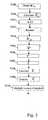
- Fig. 3represents the algorithm executed by the calculation module according the first aspect of the invention.
- the code of this flow chartis for example stored in a non volatile memory of the memory 203 of the calculation module 110.
- the calculation module 110executes the instructions associated to the algorithm described in the Fig. 3 .
- the calculation module 110obtains the estimated correlation matrix R TX .
- the estimated correlation matrix R TXis received through the uplink MIMO channel of the telecommunication network 150 and from the correlation matrix estimator 120 of the mobile station 20.
- the estimated correlation matrixis then stored in the random access memory of the memory 203.
- the correlation matrix R TXcan be also estimated by the calculation module 110 when the uplink channels are considered to have long term statistics equal to the long term statistics of the downlink channels.
- the time and/or frequency dimensionis included in the channel description, so that the coding solution is a STF code. It has space and a time and/or a frequency dimension.
- the processor 202executes an eigenvalue decomposition noted EVD of the matrix R ⁇ T ⁇ X ⁇ .
- the processor 203reorders the eigenvalues of the matrix ⁇ according to a predetermined criterion, preferably from the highest value to the lowest one.
- the processor 202reorders the column vectors of ⁇ accordingly and the line vectors of ⁇ ' accordingly.
- the processor 202forms a matrix ⁇ ' which is a diagonal matrix made of the 2 Q strongest eigenvalues of R ⁇ T ⁇ X ⁇ .
- the processor 202forms a matrix ⁇ ' which is made of the related 2 Q eigenvectors of the strongest eigenvalues followed by arbitrary 2 N t N -2 Q column vectors.
- the processor 202obtains the matrix V' as defined previously.
- the processor 202calculates the factor ⁇ using the following formula :
- the STF coding matrix C ⁇is transferred to the STF coding module 100.
- a next step S310vectors of a dimension of 2 Q are formed.
- Each vectorcomprises the real parts and the imaginary parts of the symbols to be transmitted which are stacked on top of each other.
- Each formed vectoris multiplied by the STF coding matrix C ⁇ for producing coded symbols to be transferred.
- the code determination module 121 of the mobile station 20executes the present algorithm in a similar way as the one disclosed here in order to calculate the STF coding matrix C ⁇ used by the decoding module 123 of the mobile station 20.
- the received symbolsa group into vectors of dimension 2 Q which are each multiplied by the STF decoding matrix calculated from an eigenvalue decomposition of a matrix obtained by calculating at least the Kronecker product of the identity matrix of size N for producing estimated symbols.
- the STF coding matrix C ⁇is transferred to the code determination module 121 of the mobile station 20.
- C ⁇is computed by the code determination module 121 and transferred by the mobile station 20 to the base station 10.
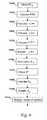
- Fig. 4represents the algorithm executed by the calculation module according the second aspect of the invention.
- the code of this flow chartis for example stored in a non volatile memory of the memory 203 of the calculation module 110. Regularly, at a frequency that depends on the mobile station maximum Doppler Frequency, the calculation module 110 executes the instructions associated to the algorithm described in the Fig. 4 .
- the calculation module 110obtains the conjugate of the estimated correlation matrix R* TX.
- the estimated correlation matrix R TXis received through the uplink MIMO channel of the telecommunication network 150 and from the correlation matrix estimator 120 of the mobile station 20.
- the estimated correlation matrixis then stored in the random access memory of the memory 203.
- the conjugate of the correlation matrix R* TXcan be also estimated by the calculation module 110 when the uplink channels are considered to have long term statistics equal to the long term statistics of the downlink channels.
- the processor 202calculates an eigenvalue decomposition noted EVD of the conjugate of the estimated correlation matrix R * TX.
- Uis the matrix of the eigenvectors of the conjugate of the estimated correlation matrix R* TX
- U His the conjugate transpose of the matrix U
- ⁇is the matrix of the eigenvalues of the conjugate of the estimated correlation matrix R* TX .
- the processor 202calculates the Kronecker product of the identity Matrix I N of dimension N and the matrix U.
- the resulting matrixis noted the matrix U' .
- the processor 202calculates the Kronecker product of the identity Matrix I N and the matrix ⁇ .
- the resulting matrixis called the matrix ⁇ ' which is a diagonal matrix comprising the eigenvalues.
- the processor 202calculates the Kronecker product of the identity Matrix I N and the matrix U H .
- the resulting matrixis called the matrix U' H .
- the time and/or frequency dimensionis included in the channel description, so that the coding solution is a true linear STF pre-coding. It has space and a time and/or a frequency dimension.
- the processor 202reorders the eigenvalues of the matrix ⁇ ' according to a predetermined criterion, preferably from the highest values to the lowest one.
- the processor 202reorders the column vectors of U ' accordingly and the line vectors of U' H accordingly.
- the processor 202forms a matrix ⁇ ' Q which is a diagonal matrix made of the Q strongest eigenvalues of ⁇ '.
- the processor 202obtains the matrix V H as defined previously.
- the STF linear pre-coding matrix C cis transferred to the STF pre-coding module 100.
- the symbols to be transmittedare grouped into vectors of Q complex elements. Each vector of dimension Q is multiplied by the STF coding matrix C c at step 5410.
- the code determination module 121 of the mobile station 20executes the present algorithm in a similar way as the one disclosed here in order to calculate the STF linear pre-coding matrix C c used by the decoding module 123 of the mobile station 20.
- the received symbolsa group into symbols of dimension Q which are each multiplied by the STF linear decoding matrix calculated from an eigenvalue decomposition of a matrix obtained by calculating at least the Kronecker product of the identity matrix of size N for producing estimated symbols.
- C cis computed by the code determination module 121 and transferred by the mobile station 20 to the base station 10.
- the STF linear pre-coding matrix C cis transferred to the code determination module 121 of the mobile station 20.
Landscapes
- Engineering & Computer Science (AREA)
- Computer Networks & Wireless Communication (AREA)
- Signal Processing (AREA)
- Radio Transmission System (AREA)
- Mobile Radio Communication Systems (AREA)
Abstract
Description
- The present invention relates to a method for transmitting symbols through at least a communication channel in a telecommunication system including at least one transmitter provided with at least two transmitting antennas and at least one receiver provided with at least one receiving antenna, which method includes an encoding step
wherein vectors comprising symbols are multiplied by a coding matrix for producing symbols to be transmitted over the at least one communication channel established between the transmitter and the receiver. - More precisely, the present invention is particularly adapted when the transmitter has not a precise knowledge of the communication channels and when the receiver is a Minimum Mean Square Error (MMSE) receiver which has a very good knowledge of the communication channels.
- Telecommunication systems in which a plurality of antennas are used at a receiver end and/or at a transmitter end of a wireless link, are called Multiple Input Multiple Output systems (further referred to as MIMO systems). MIMO systems have been shown to offer large transmission capacities compared to those offered by single antenna systems. In particular, MIMO capacity increases linearly with the number of transmitting or receiving antennas, whichever the smallest, for a given Signal-to-Noise Ratio and under favourable uncorrelated channel conditions. Such MIMO techniques can be combined with multi-carrier modulation techniques based on OFDM (standing for Orthogonal Frequency Division Multiplex), whose use in future wireless systems is also considered.
- Dedicated coding has been investigated over the past years to properly exploit the possibilities of MIMO. These coding schemes generally span both the space dimension and the time dimension, hence their name of Space Time Codes (ST Codes). They may alternatively span also the frequency dimension eg. several subcarriers in an OFDM system, and are then called Space-Time Frequency Codes (STF Codes).
- According to the invention, a STF code is a coding scheme which spans the space and time and/or frequency dimensions. An STF code can be a coding scheme which spans the space and time dimensions or a coding scheme which spans the space and frequency dimensions or a coding scheme which spans the space and time and frequency dimensions.
- The purpose of these coding schemes is to use the spatial dimension of MIMO with good performance. The spatial dimension can be used to increase the data rate at a given error rate performance. This is achieved through spatial multiplexing as it is disclosed in the paper ofG. D. Golden, G. J. Foschini, R. A. Valenzuela, P. W. Wolniansky, entitled "Detection Algorithm and Initial Laboratory Results using the V-BLAST Space-Time Communication Architecture" , published in Electronics Letters, Vol. 35, No. 1, Jan. 7, 1999, pp. 14-15.
- The spatial dimension can also be used to improve the error rate performance at a fixed data rate. As example, codes exploit the transmit and receive antennas diversity as it is disclosed in the paper ofS. M. Alamouti, entitled "A simple transmitter diversity scheme for wireless communications" published in IEEE J. Selected Areas in Communications, vol. 16, pp.1451-1458, Oct. 1998.
- From a general point of view, STF codes are used to address a variety of cases combining these two possibilities of spatial multiplexing and performance improvement through space diversity.
- The most popular type of STF codes referred as space time block codes, as opposed to space-time trellis codes, are represented with concise matrix notations,
where the number of possible codewords depends on the matrix size. These codes are ideally decoded by exhaustive search like Maximum Likelihood (ML) decoding, or A Posteriori Probability (APP) decoding, or approximations of it, such as sphere decoding and list sphere decoding. - Especially, they are designed assuming such type of ideal receivers. The main issue is that the decoder complexity is very large as it is exponential with the input size in the case of ML or APP decoding, and polynomial with the input size in the case of sphere decoding or list sphere decoding, which makes their implementation in a mobile receiver difficult to realize, especially at high spectral efficiencies.
- On the contrary, MMSE decoding, which is a generic well known type of decoding, has rather low complexity. It is a very good candidate for a practical implementation.
- Besides, the existing STF block codes are generally designed assuming perfect transmit de-correlation, which is neither the case in reality where residual correlation exists between the transmit antennas on one side and receive antenna or antennas on the other side. The residual correlation is due to the antennas collocation and due to propagation conditions.
- The
US 2005/0041751 patent application discloses a pre-encoding step using a linear pre-encoding matrix. - The thesis dated April 2001 entitled "Linear precoding and decoding for MIMO wireless channels" of Hemanth Sampath discloses linear precoding and decoding for MIMO wireless channels.
- The present invention proposes a STF Code design or a STF pre-coding design under more realistic assumptions of residual and known transmit correlation and assuming the use of MMSE decoder at the receiver side.
- To that end, the present invention concerns a method for transmitting symbols through at least a channel in a telecommunication system including at least one transmitter provided with at least two transmitting antennas and at least one receiver provided with at least one receiving antenna, the method includes an encoding step wherein a vector comprising symbols is multiplied by a coding matrix for producing coded symbols to be transmitted over the at least one communication channel established between the transmitter and the receiver, characterised in that the coding matrix is calculated from an eigenvalue decomposition of a matrix obtained by calculating at least the Kronecker product of the identity matrix of sizeN, N being the time and/or the frequency dimension of the code and a matrix obtained from an estimated correlation matrix of the response of the channel.
- According to still another aspect, the present invention concerns a device for transmitting symbols through at least a channel in a telecommunication system including at least one transmitter provided with at least two transmitting antenna and at least one receiver provided with at least one receiving antennas, the device comprising encoding means wherein a vector comprising symbols is multiplied by a coding matrix for producing coded symbols to be transmitted over the at least one communication channel established between the transmitter and the receiver, characterised in that the device comprises means for calculating the coding matrix from an eigenvalue decomposition of a matrix obtained by calculating at least the Kronecker product of the identity matrix of sizeN, N being the time and/or the frequency dimension of the code and a matrix obtained from an estimated correlation matrix of the response of the channel.
- Thus, through the Kronecker product, the time and/or frequency dimension is included in the channel description. It has space and a time and/or a frequency dimension, which allows to design codes considering jointly these three dimensions or part of these dimensions.
- According to a first aspect of the present invention, the coding matrixC̃ is a real matrix calculated from an eigenvalue decomposition of a matrix


- Thus, through the Kronecker product, the time and/or frequency dimension is included in the channel description, so that the coding solution is a STF code.
- According to a particular feature, the matrix


- According to a particular feature, the eigenvalue decomposition of the matrix


- Thus, the performances are improved.
- According to a particular feature, the matrixΛ̃' is formed by selecting the 2*Q largest non zero diagonal values of the matrixΛ̃, whereinQ is the number of symbols comprised within the vector comprising symbols and the matrixŨ' comprises the 2*Q columns of the matrixŨ associated, in the same order, with the 2*Q largest values selected for the matrixΛ̃'.
- Thus, the performances are improved.
- According to a particular feature, the numberQ of symbols comprised within the vector comprising symbols is not divisible by the dimensionN.
- According to a particular feature, the coding matrix C̃ is calculated from a third matrixV't, the matrixV't being the transpose of an orthonormal matrixV' of
dimension 2*Q. - According to a particular feature, the matrixV' is obtained from a Discrete Fourier Transform matrix or the matrixV' is an Hadamard matrix of
dimension 2*Q when 2*Q is a power of two. - It has to be noted here that, a matrix of dimensionQ or 2Q should be understood as a square matrix of dimensionQ byQ or 2*Q by 2*Q.
- According to a particular feature, the coding matrixC̃ is calculated using the following formula:


- According to a second aspect of the present invention, the coding matrix is a STF linear pre-coding matrixCc obtained fromR*TX , which is the conjugate matrix of the estimated transmit correlation matrixRTX of the frequency response of the channel.
- Thus, through the Kronecker product, the time and/or frequency dimension is included in the channel description.
- According to a particular feature, the eigenvalue decomposition of the matrix


- Thus, through the Kronecker product, the time and/or frequency dimension is included in the channel description.
- According to a particular feature, the matrixΛ' is formed by selecting theQ largest non zero diagonal values of the matrixΛ, whereinQ is the number of symbols comprised within the vector comprising symbols and the matrixU' comprises theQ columns of the matrixU associated with theQ largest values selected for the matrixΛ'.
- According to a particular feature, the numberQ of symbols comprised within the vector comprising symbols is not divisible by the dimensionN .
- According to a particular feature, the STF linear pre-coding matrixCc is calculated from a third matrixVH, the matrixVH being the transpose conjugate of a unitary matrixV of dimensionQ.
- According to a particular feature, the matrixV is a Discrete Fourier Transform matrix or the matrixV is an Hadamard matrix of dimensionQ whenQ is a power of two.
- According to a particular feature, the STF linear pre-coding matrix isCc is calculated using the following formula :


- According to still another aspect, the present invention concerns a method for decoding symbols by a receiver provided with at least one receiving antenna, the symbols being transmitted by at a transmitter provided with at least two transmitting antennas through at least a channel in a telecommunication system, the method including a decoding step wherein a vector comprising received symbols is multiplied by a decoding matrix for producing decoded symbols, characterised in that the decoding matrix is calculated from an eigenvalue decomposition of a matrix obtained by calculating at least the Kronecker product of the identity matrix of sizeN, N being the time and/or the frequency dimension of the code and a matrix obtained from an estimated correlation matrix of the response of the channel.
- According to still another aspect, the present invention concerns a device for decoding symbols being transmitted by one transmitter provided with at least two transmitting antennas through at least a channel in a telecommunication system, the device comprising decoding means wherein a vector comprising received symbols is multiplied by a decoding matrix for producing decoded symbols, characterised in that the device comprises means for calculating a decoding matrix from an eigenvalue decomposition of a matrix obtained by calculating at least the Kronecker product of the identity matrix of sizeN, N being the time and/or the frequency dimension of the code and a matrix obtained from an estimated correlation matrix of the response of the channel.
- According to still another aspect, the present invention concerns a computer program which can be directly loadable into a programmable device, comprising instructions or portions of code for implementing the steps of the method according to the invention, when said computer program is executed on a programmable device. Since the features and advantages relating to the computer program are the same as those set out above relating to the method and device according to the invention, they will not be repeated here.
- The characteristics of the invention will emerge more clearly from a reading of the following description of an example embodiment, the said description being produced with reference to the accompanying drawings, among which:
Fig. 1 represents a telecommunication system according to the invention ;Fig. 2 represents the calculation module which calculates the STF Code according to the first aspect of the invention or the linear STF pre-coding matrix according to the second aspect of the invention ;Fig. 3 represents the algorithm executed by the calculation module according the first aspect of the invention ;Fig. 4 represents the algorithm executed by the calculation module according the second aspect of the invention.Fig. 1 represents a telecommunication system according to the invention.- The
Fig. 1 discloses twocommunication devices telecommunication network 150. - The
communication device 10 is preferably a base station which transfers to thecommunication device 20, which is preferably a mobile terminal, data through a MIMO downlink transmission channel of atelecommunication network 150. - For the sake of simplicity, only one
mobile terminal 20 is shown inFig. 1 . Naturally a more important number of mobile terminals receive or transmit data from or to thebase station 10 in thetelecommunication network 150 wherein the present invention is used. - The
base station 10 has a plurality ofNt antennas respectively notedAntt 1,Antt 2...and AnttNt in theFig. 1 and themobile terminal 20 has at least one antenna. As example, the mobile terminal has a plurality ofNr antennas respectively notedAntr 1,Antr 2 to AntrNr creating then a MIMO downlink transmission channel withNt transmit antennas andNr receive antennas. - Preferably and for the sake of simplicity, the transmission of data uses an Orthogonal Frequency Division Multiplexing (OFDM) modulation withNc modulated sub-carriers, each sub-carrier experiences a MIMO flat fading channel, provided that the OFDM parameters are well chosen in particular with respect to the channel delay spread. The method described in the present invention can be extended to single carrier systems experiencing inter symbol interferences. In that case, the flat fading MIMO channel to be considered is the delay domain equalized channel.
- The modulated symbols are transmitted over the space, time and frequency dimensions using a Space-Time-Frequency (STF) block code or a linear STF pre-coder of dimensionsNt*Ntime*Nfreq, whereinNtime is the time dimension of the code in terms of OFDM symbols andNfreq is the frequency dimension of the code in terms of subcarriers. Thus,N= Ntime*Nfreq equivalently represents the time dimension for a Space Time (ST) code or a linear ST pre-coder, the frequency dimension for a Space Frequency (SF) code or a linear SF pre-coder and a mix of both for a Space Time Frequency (STF) code or a linear STF pre-coder. As it has been already mentioned, STF, ST, SF codes are considered in the present invention as STF codes.
- It has to be noted here that ifNfreq = 1,N refers to the particular case of Space Time coding and ifNtime = 1,N designates the particular case of Space Frequency coding.
- The
mobile station 20 implements, according to the invention, a Minimum Mean Square Error receiver which estimates the signal encoded by the STF code according to a first aspect of the invention, or a Minimum Mean Square Error receiver which estimates the signal pre-encoded by the linear STF pre-coder at thebase station 10 according to the second aspect of the invention. - The
mobile station 20 comprises achannel estimation module 122 that estimates the instantaneous channel response used by the MMSE receiver. Themobile station 20 comprises also acorrelation matrix estimator 120 which estimates, from several realisations of the instantaneous channel response used by the MMSE receiver, a correlation matrix of the response of the channel notedRTX. - More precisely, the correlation matrix of the response of the channelRTX is an estimation of the transmit correlation matrix of the MIMO channel of the
telecommunication network 150. - The transmit correlation matrixRTX of the MIMO channel of the
telecommunication network 150 is transmitted by themobile station 20 to thebase station 10 through an uplink MIMO channel of thetelecommunication network 150. - The
mobile station 20 comprises also a code determination module 121 which determines the code used by thebase station 10 according to the correlation matrixRTX of the MIMO channel of thetelecommunication network 150. - The
mobile station 20 needs also to know at least a part of the STF coder or of the linear STF pre-coder used by thebase station 10 in order to perform the decoding. Themobile station 20 computes the decoding matrix to be used as thebase station 10 computes the coding matrix to be used from the knowledge of the estimated correlation matrixRTX. - The computed matrix is transferred to the
decoding module 123 of themobile station 20 in order to decode the received symbols into estimated symbols. - In a variant of realisation, instead of transferring the transmit correlation matrixRTX of the MIMO channel of the
telecommunication network 150 to thebase station 10, themobile station 20 transfers the coding matrix elements to thebase station 10 through the uplink MIMO channel of thetelecommunication network 150. - In another variant of realisation, the
base station 10 determines the coding matrix to be used by thebase station 10 according to the received correlation matrix and transfers it to themobile station 20. - The
base station 10 comprises at least acoding module 100 and acalculation module 110. Thecoding module 100 is, according to the first aspect of the invention, a STF coding module, or a linear STF pre-coder, according to the second aspect of the invention. - The
STF coding module 100 forms vectors comprising symbols to be transmitted and multiplies each formed vector by a coding matrix for producing coded symbols to be transmitted over the MIMO channel. - The
calculation module 110 has a long term or no channel knowledge. It means that thecalculation module 110 receives from time to time the estimated correlation matrixRTX from themobile station 20 and determines a STF coding matrixC according to the first aspect of the invention, or a STF linear pre-coding matrixCc according the second aspect of the invention, from the received estimated correlation matrixRTX, that minimizes the average, with respect to the fast fading process, residual Mean Square Error at the receiver side after MMSE decoding. - The received estimated correlation matrixRTX is representative of the macroscopic environment in the vicinity of the base station. The received estimated correlation matrixRTX is then constant when the channel variations are restricted to the fast fading process. Considering the link between a base station and a mobile station, the estimated correlation matrixRTX is therefore constant during a period that is inversely proportional to the speed of the mobile and the update frequency of the estimated correlation matrixRTX should therefore be set accordingly.
- In practice, the update period is large in comparison with the typical elementary transmission duration so that the update of the estimated correlation matrixRTX is inexpensive in term of the required feedback bandwidth and in term of workload for the transmit and the receiving sides.
- In a variant of realisation, the
calculation module 110, instead of receiving from time to time the estimated correlation matrixRTX from themobile station 20, receives the coding matrix or the linear pre-coding matrix computed by themobile station 10 through the uplink channel of thetelecommunication network 150. - The
calculation module 110 will be described in detail in reference toFig. 2 . - The theoretical bases of the determination of the STF coding matrixC̃ and the STF linear pre-coding matrix Cc are now disclosed.
- The following equation describes the discrete time downlink received signal
where the signal of one user is transmitted using a STF code :
- For the following, the ensemble of real numbers is notedR and the ensemble of complex numbers is notedC.
whereR' is aNrN*1 complex vector made of the column vectorsRi ofR ∈CNr*N stacked on top of each other, each of sizeNr*1 andH' is a block diagonal MIMO channel matrix, where each of theN blocks corresponds to a time index for ST codes, or a frequency index for SF codes, or a mixed time and frequency index for STF codes:
whereS ∈CQ*I is the vector containing the Q modulated symbols, Q being the number of symbols per STF codeword.SR is the real part Re(S) ofS andSI is the imaginary part Im(S) of S. Each symbol of S has an average energy equal to 1. - The STF code in
equation EQ 1 is described with two complex matricesEc andFc, one encoding the real part ofS, the other one the imaginary part. Equivalently, the STF code can be described with two other complex matricesCc andDc encoding respectivelyS andS*. It has to be noted here thatS* denotes the conjugate of the matrix S.
whereEc ∈CNtN*Q,Fc ∈CNtN*Q are the code matrices that respectively encode the real part of S and the imaginary part of S.
It has to be noted thatEc andFc fully describe the STF code and describe in the most general manner all block STF codes from spatial multiplexing as disclosed in the paper of G. D. Golden, G. J. Foschini, R. A. Valenzuela, P. W. Wolniansky, entitled "Detection Algorithm and Initial Laboratory Results using the V-BLAST Space-Time Communication Architecture", to true STF codes, such as disclosed in the paper of Alamouti, "A simple transmitter diversity scheme for wireless communications". - This gives the following equation, equivalent to EQ 1:

- WhenDc is constrained to0, the resulting STF code is a linear STF pre-coding. Linear STF pre-coding means that the output of the STF pre-encoding process is a linear operation on the input complex vector S. In this case equation EQ 3 can be written as:

- In the case of true STF coding, no restriction is put on the coding matricesEc andFc. It is convenient to rewrite
EQ 1 with a linear form:
- Rewriting EQ 4 with real matrices, we obtain the equivalent equation:

- The MIMO transmission channel of the telecommunication network is assumed to be flat fading, it means that the discrete time channel response between each pair of transmit and receive antennas is modelled as a complex coefficient (H)ij, wherei is the receive antenna index andj is the transmit antenna index. Such hypothesis is well suited to OFDM modulation since each subcarrier indeed experiences flat fading, the channel coefficients are equal to the channel frequency response at the subcarrier frequency, given by the corresponding sample of the FFT of the channel impulse response between the pair of antennas.
- We denoteRTX the correlation matrix at the transmitter side andB its square root, so thatBHB=RTX
and thus the channel matrix is modelled as:
- It has to be noted here that in order to simplify the notations the indexest andf ofH andG are dropped.
- Combining EQ 5 and
EQ 2,H' becomes:
- The independently and identically distributed complex centered Gaussian matricesGi may be equal or more or less correlated for different indexesi.
- It has to be noted here that the
receiver 20 is assumed to have a perfect instantaneous knowledge of the channel of thetelecommunication network 150, which is, as example, commonly implemented by using appropriate pilot symbols. - Considering that the
receiver 20 comprises an MMSE STF detector which has a perfect instantaneous channel knowledge, theSTF coding module 100 or the linearSTF pre-coding module 100 uses a STF code that minimizes the residual Mean Square Error at the receiver side after detection, averaged over the fast fading process, i.eGi in EQ 6. - According to the first aspect of the invention, we will now focus on the basic principle of the characterisation of the STF coding matrix for STF code.
- As already disclosed, the received signal can be expressed with a linear equation provided that the processing of the real and imaginary parts are made separately.

- The STF coding matrixC̃ is found so as to minimize the average residual MSE after MMSE detection, under the transmit power constraint Tr(C̃ C̃t) = P. At high signal to noise ratio, i.eσ2 is small.C̃ is found as :


- Similarly,C̃ can be written as :

- It has to be noted here that all the involved matrices here are real matrices and thatV' is only required to be an orthonormal 2Q*2Q matrix.
- According to a preferred mode of realisation, the matrixV't is a transpose matrix of a matrixV' which can be refined so as to maximize the minimum average residual SINR per detected real dimension after MMSE equalization.V' can be chosen as a Hadamard matrix of dimension 2Q when 2Q is a power of 2.
- V't can also be obtained from a Discrete Fourier Transform matrixF using the following formula:

- According to the second aspect of the invention, we will now focus on the basic principle of the characterisation of the STF linear pre-coding matrix.
- Starting with equation EQ 3 whereDc is set to zero, we consider that the receiver implements an MMSE STF detector, we assume that perfect instantaneous channel knowledge is available at the receiver side.
- The coding matrixCC is found so as to minimize the average residual MSE after MMSE detection, under the transmit power constraintTr(CC CCt) = P.
- We use the Eigen Value Decomposition (EVD) ofR*TX:

- The EVD of


- At high signal to noise ratio,CC is found as :

- α is a normalization coefficient that is used to satisfy the transmit power constraint. For instance

- Similary,CC can be written as :

- WhereU" is aNtN*Q matrix made of the firstQ columns ofU'.
- In EQ 7,U', α andΛ'Q are fully defined,V is only required to be unitary. However, whereas any unitary matrixV gives the same average value of the MSE with respect to the fast fading process, the choice ofV influences the resulting Bit Error Rate (BER).
- According to a preferred embodiment,V can be determined so as to maximize the minimum average signal to noise plus interference ratio denoted SINR per dimension of the detected signal. Discrete Fourier matrices and Hadamard matrices are found to be local optima of this problem.
- Thus,V can be chosen, according to a particular feature as a Discrete Fourier Transform or a Hadamard matrix of dimensionQ.
- In the case of Hadamard matrices, Q needs to be a power of two.
- According to a variant,V can be chosen as a unitary linear precoding matrix such as described byS. Galliou, J. C. Belfiore in "Une nouvelle famille de codes espace-temps linéaires, de rendement et de diversité maximaux" , Proc. Propagation Electromagnétique dans l'Atmosphère du Décamétrique à l'Angström, Rennes 13, 14, 15 mars 2002, pp. 117-118 or byN. Gresset, J. Boutros, L. Brunel in "Optimal linear precoding for BICM over MIMO channels," Proc. of the IEEE International Symposium on Information Theory, Chicago, p. 66, Jun. 2004.
Fig. 2 represents the calculation module which calculates the STF Code according to the first aspect of the invention or the STF linear pre-coding matrix according to the second aspect of the invention.- The
calculation module 110 has an architecture based on components connected together by abus 201 and aprocessor 202 controlled by a program as disclosed inFig. 3 . Thecalculation module 110 can be integrated in one or several integrated circuits. - The
calculation module 110 comprises memory means 203 made by at least one random access memory and a non-volatile memory. - The
bus 201 links theprocessor 202 to the memory means 203, the interface ANT I/F 206 which receives the estimated correlation matrixRTX or the conjugate of the estimated correlation matrixR*TX from themobile station 20 and the interface cod I/F 207 which enables the transfer to theSTF coding module 100 of the calculated STF linear pre-coding matrixCc or the STF coding matrixC̃ according to the obtained correlation matrixRTX. - The random access memory contains registers intended to receive variables, digital data and intermediate processing values. The non-volatile memory stores the program which enables the module and, in particular, the
processor 202, to operate. Theprocessor 202 controls the operation of the principal components of thecalculation module 110. Fig. 3 represents the algorithm executed by the calculation module according the first aspect of the invention.- The code of this flow chart is for example stored in a non volatile memory of the
memory 203 of thecalculation module 110. Regularly, at a frequency that depends on the mobile station maximum Doppler Frequency, which typically corresponds to a refreshing period of a few hundreds of milliseconds at the carrier frequency of 5 GHz and a mobile station speed of 3 meters per second, thecalculation module 110 executes the instructions associated to the algorithm described in theFig. 3 . - At step S300 the
calculation module 110 obtains the estimated correlation matrixRTX. The estimated correlation matrixRTX, is received through the uplink MIMO channel of thetelecommunication network 150 and from thecorrelation matrix estimator 120 of themobile station 20. The estimated correlation matrix is then stored in the random access memory of thememory 203. - It has to be noted here that the correlation matrixRTX can be also estimated by the
calculation module 110 when the uplink channels are considered to have long term statistics equal to the long term statistics of the downlink channels. - At next step S301, the
processor 202 calculates the matrixR̃*Tx using the following formula:


- Through the Kronecker product, the time and/or frequency dimension is included in the channel description, so that the coding solution is a STF code. It has space and a time and/or a frequency dimension.
- At next step S302 the
processor 202 executes an eigenvalue decomposition noted EVD of the matrix


- At next step S303, the
processor 203 reorders the eigenvalues of the matrixΛ̃ according to a predetermined criterion, preferably from the highest value to the lowest one. Theprocessor 202 reorders the column vectors ofŨ accordingly and the line vectors ofŨ' accordingly. - At next step S304, the
processor 202 forms a matrixΛ̃' which is a diagonal matrix made of the 2Q strongest eigenvalues of
- At next step S305, the
processor 202 forms a matrixŨ' which is made of the related 2Q eigenvectors of the strongest eigenvalues followed by arbitrary 2NtN-2Q column vectors. - At next step S306, the
processor 202 obtains the matrixV' as defined previously. - At next step S307, the
processor 202 calculates the factor β using the following formula : 
- At next step S308, the
processor 202 calculates the STF coding matrixC̃ using the following formula:
- At next step S309, the STF coding matrixC̃ is transferred to the
STF coding module 100. - A next step S310, vectors of a dimension of 2Q are formed. Each vector comprises the real parts and the imaginary parts of the symbols to be transmitted which are stacked on top of each other. Each formed vector is multiplied by the STF coding matrixC̃ for producing coded symbols to be transferred.
- It has to be noted here that, according to a particular feature, the code determination module 121 of the
mobile station 20 executes the present algorithm in a similar way as the one disclosed here in order to calculate the STF coding matrixC̃ used by thedecoding module 123 of themobile station 20. In such case, the received symbols a group into vectors of dimension 2Q which are each multiplied by the STF decoding matrix calculated from an eigenvalue decomposition of a matrix obtained by calculating at least the Kronecker product of the identity matrix of sizeN for producing estimated symbols. - It has to be noted here that, according to a variant, the STF coding matrixC̃ is transferred to the code determination module 121 of the
mobile station 20. - According to a particular feature,C̃ is computed by the code determination module 121 and transferred by the
mobile station 20 to thebase station 10. Fig. 4 represents the algorithm executed by the calculation module according the second aspect of the invention.- The code of this flow chart is for example stored in a non volatile memory of the
memory 203 of thecalculation module 110. Regularly, at a frequency that depends on the mobile station maximum Doppler Frequency, thecalculation module 110 executes the instructions associated to the algorithm described in theFig. 4 . - At step S400 the
calculation module 110 obtains the conjugate of the estimated correlation matrixR*TX. The estimated correlation matrixRTX is received through the uplink MIMO channel of thetelecommunication network 150 and from thecorrelation matrix estimator 120 of themobile station 20. The estimated correlation matrix is then stored in the random access memory of thememory 203. - It has to be noted here that the conjugate of the correlation matrixR*TX can be also estimated by the
calculation module 110 when the uplink channels are considered to have long term statistics equal to the long term statistics of the downlink channels. - At next step S401, the
processor 202 calculates an eigenvalue decomposition noted EVD of the conjugate of the estimated correlation matrixR*TX. R*TX is then decomposed in
- Wherein U is the matrix of the eigenvectors of the conjugate of the estimated correlation matrixR*TX, UH is the conjugate transpose of the matrixU andΛ is the matrix of the eigenvalues of the conjugate of the estimated correlation matrixR*TX.
- At next step S402, the
processor 202 calculates the Kronecker product of the identity MatrixIN of dimensionN and the matrixU. The resulting matrix is noted the matrixU'. - At next step S403, the
processor 202 calculates the Kronecker product of the identity MatrixIN and the matrixΛ. The resulting matrix is called the matrixΛ' which is a diagonal matrix comprising the eigenvalues. - At next step S404, the
processor 202 calculates the Kronecker product of the identity MatrixIN and the matrixUH. The resulting matrix is called the matrixU'H. - Through the Kronecker product, the time and/or frequency dimension is included in the channel description, so that the coding solution is a true linear STF pre-coding. It has space and a time and/or a frequency dimension.
- At next step S405, the
processor 202 reorders the eigenvalues of the matrixΛ' according to a predetermined criterion, preferably from the highest values to the lowest one. Theprocessor 202 reorders the column vectors ofU' accordingly and the line vectors ofU'H accordingly. - At next step S406, the
processor 202 forms a matrix Λ'Q which is a diagonal matrix made of theQ strongest eigenvalues ofΛ'. - At next step S407, the
processor 202 obtains the matrixVH as defined previously. - At next step S408, the
processor 202 calculates the STF linear pre-coding matrixCc using the following formula:

- At next step S409, the STF linear pre-coding matrix Cc is transferred to the
STF pre-coding module 100. - The symbols to be transmitted are grouped into vectors ofQ complex elements. Each vector of dimension Q is multiplied by the STF coding matrixCc at step 5410.
- It has to be noted here that the code determination module 121 of the
mobile station 20 executes the present algorithm in a similar way as the one disclosed here in order to calculate the STF linear pre-coding matrix Cc used by thedecoding module 123 of themobile station 20. In such case, the received symbols a group into symbols of dimensionQ which are each multiplied by the STF linear decoding matrix calculated from an eigenvalue decomposition of a matrix obtained by calculating at least the Kronecker product of the identity matrix of sizeN for producing estimated symbols. - According to a particular feature,Cc is computed by the code determination module 121 and transferred by the
mobile station 20 to thebase station 10. - It has to be noted here that, according to a variant, the STF linear pre-coding matrixCc is transferred to the code determination module 121 of the
mobile station 20. - Naturally, many modifications can be made to the embodiments of the invention described above without departing from the scope of the present invention as defined by the appended claims.


Claims (22)
- Method for transmitting symbols through at least a channel in a telecommunication system including at least one transmitter (10) provided with at least two transmitting antennas (Antt 1, Antt 2) and at least one receiver provided with at least one receiving antenna (Antr 1), the method includes an encoding step (S310, S410) wherein a vector comprising symbols is multiplied by a coding matrix for producing coded symbols to be transmitted over the at least one communication channel established between the transmitter (10) and the receiver (20),characterised in that the coding matrix is calculated (S302, S401) from an eigenvalue decomposition of a matrix obtained by calculating at least the Kronecker product (S301) of the identity matrix of sizeN and the estimated correlation matrix of the response of the channel, or by calculating at least the Kronecker product (S402, S403, S404) of the identity matrix of sizeN and matrices obtained from the conjugate of the estimated correlation matrix of the response of the channel,N being the time and/or the frequency dimension of the code
- Method according to claim 1,characterised in that the coding matrixC̃ is calculated from an eigenvalue decomposition of a matrix


- Method according to claim 2,characterised in that the matrix


wherein ⊗ is the Kronecker product. - Method according to claim 3,characterised in that the eigenvalue decomposition of the matrix


- Method according to claim 4,characterised in that the matrix Λ̃' is formed by selecting the 2*Q largest non zero diagonal values of the matrix Λ̃, whereinQ is the number of symbols comprised within the vector comprising symbols and the matrixŨ' comprises the 2*Q columns of the matrixŨ associated, in the same order, with the 2*Q largest values selected for the matrix Λ̃'.
- Method according to claim 5,characterised in that the numberQ of symbols within the vector comprising symbols is not divisible by the dimensionN.
- Method according to claim 6,characterised in that the coding matrixC̃ is calculated from a third matrixV't, the matrixV't being the transpose of an orthonormal matrixV' of dimension 2*Q.
- Method according to claim 7,characterised in that the matrixV' is obtained from a Discrete Fourier Transform matrix.
- Method according to claim 7,characterised in that the matrixV' is an Hadamard matrix of dimension 2*Q when 2*Q is a power of two.
- Method according to claims 7 to 9,characterised in that the coding matrixC̃ is calculated (S308) using the following formula :


- Method according to claim 1,characterized in that the coding matrix is a STF linear pre-coding matrixCc and the matrix obtained from an estimated correlation matrix of the response of the channelR*TX is the conjugate matrix of the estimated correlation matrixRTX of the frequency response of the channel.
- Method according to claim 11,characterised in that the eigenvalue decomposition of the matrix


- Method according to claim 12,characterised in that the matrix Λ' is formed by selecting theQ largest non zero diagonal values of the matrix Λ, whereinQ is the number of symbols comprised within the vector comprising symbols and the matrix U' comprises theQ columns of the matrixU associated with theQ largest values selected for the matrix Λ'.
- Method according to claim 13,characterised in that the numberQ of symbols within the vector comprising symbols is not divisible by the dimensionN.
- Method according to claim 14,characterised in that the STF linear pre-coding matrixCc is calculated from a third matrixVH, the matrixVH being the transpose conjugate of a unitary matrixV of dimensionQ.
- Method according to claim 15,characterised in that the matrixV is a Discrete Fourier Transform matrix.
- Method according to claim 15,characterised in that the matrixV is an Hadamard matrix of dimensionQ whenQ is a power of two.
- Method according to claims 15 to 17,characterised in that the STF linear pre-coding matrix isCc is calculated (S408) using the following formula:

, wherein
- Device for transmitting symbols through at least a channel in a telecommunication system including at least one transmitter (10) provided with at least two transmitting antenna (Antt 1, Antt 2) and at least one receiver (20) provided with at least one receiving antennas (Antr 1), the device comprising encoding means (100) wherein a vector comprising symbols is multiplied by a coding matrix for producing coded symbols to be transmitted over the at least one communication channel established between the transmitter and the receiver,characterised in that the device comprises means (202) for calculating the coding matrix from an eigenvalue decomposition of a matrix obtained by calculating at least the Kronecker product of the identity matrix of sizeN and the estimated correlation matrix of the response of the channel, or by calculating at least the Kronecker product of the identity matrix of sizeN and matrices obtained from the conjugate of the estimated correlation matrix of the response of the channel,N being the time and/or the frequency dimension of the code.
- Method for decoding symbols by a receiver (20) provided with at least one receiving antenna (Antr 1), the symbols being transmitted by at a transmitter (10) provided with at least two transmitting antennas (Antt 1, Antt 2) through at least a channel in a telecommunication system, the method including a decoding step wherein a vector comprising received symbols is multiplied by a decoding matrix for producing decoded symbols,characterised in that the decoding matrix is calculated from an eigenvalue decomposition of a matrix obtained by calculating at least the Kronecker product of the identity matrix of sizeN and the estimated correlation matrix of the response of the channel, or by calculating at least the Kronecker product of the identity matrix of sizeN and matrices obtained from the conjugate of the estimated correlation matrix of the response of the channel,N being the time and/or the frequency dimension of the code.
- Device (20) for decoding symbols being transmitted by one transmitter provided with at least two transmitting antennas through at least a channel in a telecommunication system, the device comprising decoding means (123) wherein a vector comprising received symbols is multiplied by a decoding matrix for producing decoded symbols,characterised in that the device comprises means for calculating a decoding matrix (121) from an eigenvalue decomposition of a matrix obtained by calculating at least the Kronecker product of the identity matrix of sizeN and the estimated correlation matrix of the response of the channel, or by calculating at least the Kronecker product of the identity matrix of sizeN and matrices obtained from the conjugate of the estimated correlation matrix of the response of the channel,N being the time and/or the frequency dimension of the code.
- Computer program which can be directly loadable into a programmable device, comprising instructions or portions of code for implementing the steps of the method according to claims 1 to 18, when said computer program is executed on a programmable device.


Priority Applications (6)
| Application Number | Priority Date | Filing Date | Title |
|---|---|---|---|
| AT05291127TATE508549T1 (en) | 2005-05-25 | 2005-05-25 | CODING MATRIX IN A MIMO SYSTEM |
| EP05291127AEP1727307B1 (en) | 2005-05-25 | 2005-05-25 | Coding matrix in a MIMO system |
| DE602005027822TDE602005027822D1 (en) | 2005-05-25 | 2005-05-25 | Encoding matrix in a MIMO system |
| US11/435,743US7672389B2 (en) | 2005-05-25 | 2006-05-18 | Method for transmitting symbols through at least a communication channel |
| CN2006100998761ACN1878159B (en) | 2005-05-25 | 2006-05-24 | Method for transmitting symbols through at least one communication channel |
| JP2006145712AJP4806294B2 (en) | 2005-05-25 | 2006-05-25 | Method and device for transmitting symbols, method and device for decoding symbols, and computer program for this method |
Applications Claiming Priority (1)
| Application Number | Priority Date | Filing Date | Title |
|---|---|---|---|
| EP05291127AEP1727307B1 (en) | 2005-05-25 | 2005-05-25 | Coding matrix in a MIMO system |
Publications (2)
| Publication Number | Publication Date |
|---|---|
| EP1727307A1 EP1727307A1 (en) | 2006-11-29 |
| EP1727307B1true EP1727307B1 (en) | 2011-05-04 |
Family
ID=34993048
Family Applications (1)
| Application Number | Title | Priority Date | Filing Date |
|---|---|---|---|
| EP05291127AExpired - LifetimeEP1727307B1 (en) | 2005-05-25 | 2005-05-25 | Coding matrix in a MIMO system |
Country Status (6)
| Country | Link |
|---|---|
| US (1) | US7672389B2 (en) |
| EP (1) | EP1727307B1 (en) |
| JP (1) | JP4806294B2 (en) |
| CN (1) | CN1878159B (en) |
| AT (1) | ATE508549T1 (en) |
| DE (1) | DE602005027822D1 (en) |
Cited By (1)
| Publication number | Priority date | Publication date | Assignee | Title |
|---|---|---|---|---|
| US11362677B2 (en) | 2018-01-12 | 2022-06-14 | Huawei Technologies Co., Ltd. | Channel encoding method and encoding apparatus |
Families Citing this family (49)
| Publication number | Priority date | Publication date | Assignee | Title |
|---|---|---|---|---|
| US7680212B2 (en)* | 2004-08-17 | 2010-03-16 | The Board Of Trustees Of The Leland Stanford Junior University | Linear precoding for multi-input systems based on channel estimate and channel statistics |
| US9071344B2 (en) | 2005-08-22 | 2015-06-30 | Qualcomm Incorporated | Reverse link interference cancellation |
| US8611305B2 (en) | 2005-08-22 | 2013-12-17 | Qualcomm Incorporated | Interference cancellation for wireless communications |
| PT3174221T (en)* | 2007-01-12 | 2018-12-19 | Ericsson Telefon Ab L M | Method and arrangement in a wireless communications system |
| WO2009084990A1 (en)* | 2007-12-27 | 2009-07-09 | Telefonaktiebolaget Lm Ericsson (Publ) | Using spatial properties of mimo channels for enhanced channel estimation in mimo systems |
| US8995417B2 (en) | 2008-06-09 | 2015-03-31 | Qualcomm Incorporated | Increasing capacity in wireless communication |
| US9237515B2 (en) | 2008-08-01 | 2016-01-12 | Qualcomm Incorporated | Successive detection and cancellation for cell pilot detection |
| US9277487B2 (en) | 2008-08-01 | 2016-03-01 | Qualcomm Incorporated | Cell detection with interference cancellation |
| CN101645757B (en)* | 2008-08-06 | 2013-06-05 | 中兴通讯股份有限公司 | Method and device for selecting precoding matrix |
| US8391392B2 (en) | 2009-01-05 | 2013-03-05 | Marvell World Trade Ltd. | Precoding codebooks for MIMO communication systems |
| US8385441B2 (en) | 2009-01-06 | 2013-02-26 | Marvell World Trade Ltd. | Efficient MIMO transmission schemes |
| US8238483B2 (en) | 2009-02-27 | 2012-08-07 | Marvell World Trade Ltd. | Signaling of dedicated reference signal (DRS) precoding granularity |
| EP3512219B1 (en)* | 2009-04-06 | 2022-05-04 | Marvell Asia Pte, Ltd. | Improved feedback strategies for multi-user mimo communication systems |
| CN102405603B (en)* | 2009-04-21 | 2015-04-29 | 马维尔国际贸易有限公司 | Method, device and system for beamforming with selective beam attenuation |
| US9160577B2 (en) | 2009-04-30 | 2015-10-13 | Qualcomm Incorporated | Hybrid SAIC receiver |
| US8675794B1 (en) | 2009-10-13 | 2014-03-18 | Marvell International Ltd. | Efficient estimation of feedback for modulation and coding scheme (MCS) selection |
| US8917796B1 (en) | 2009-10-19 | 2014-12-23 | Marvell International Ltd. | Transmission-mode-aware rate matching in MIMO signal generation |
| WO2011055238A1 (en)* | 2009-11-09 | 2011-05-12 | Marvell World Trade Ltd | Asymmetrical feedback for coordinated transmission systems |
| JP2013512593A (en) | 2009-11-27 | 2013-04-11 | クゥアルコム・インコーポレイテッド | Capacity increase in wireless communication |
| US9509452B2 (en) | 2009-11-27 | 2016-11-29 | Qualcomm Incorporated | Increasing capacity in wireless communications |
| EP2514181B1 (en)* | 2009-12-17 | 2018-10-03 | Marvell World Trade Ltd. | Mimo feedback schemes for cross-polarized antennas |
| JP6012472B2 (en)* | 2010-01-07 | 2016-10-25 | マーベル ワールド トレード リミテッド | Dedicated reference signal (DRS) precoding granularity notification, method, communication apparatus and mobile communication terminal |
| JP5258002B2 (en) | 2010-02-10 | 2013-08-07 | マーベル ワールド トレード リミテッド | Device, mobile communication terminal, chipset, and method in MIMO communication system |
| US8687741B1 (en) | 2010-03-29 | 2014-04-01 | Marvell International Ltd. | Scoring hypotheses in LTE cell search |
| KR101081317B1 (en)* | 2010-07-12 | 2011-11-08 | 전북대학교산학협력단 | Distributed ΜΙΜΟ Channel Precoding and Decoding Method in Relay-based DFF Cooperative Wireless Network |
| JP2012100254A (en) | 2010-10-06 | 2012-05-24 | Marvell World Trade Ltd | Codebook subsampling for pucch feedback |
| US8615052B2 (en) | 2010-10-06 | 2013-12-24 | Marvell World Trade Ltd. | Enhanced channel feedback for multi-user MIMO |
| DE102011115783A1 (en)* | 2010-10-12 | 2012-04-12 | Htc Corporation | Method for transmitting data symbols for transmitter in wireless communication system, involves transmitting transmission symbols according to operation of multi-input multi-output and/or orthogonal frequency-division multiplexing methods |
| US9048970B1 (en) | 2011-01-14 | 2015-06-02 | Marvell International Ltd. | Feedback for cooperative multipoint transmission systems |
| US8861391B1 (en) | 2011-03-02 | 2014-10-14 | Marvell International Ltd. | Channel feedback for TDM scheduling in heterogeneous networks having multiple cell classes |
| CN103548284B (en) | 2011-03-31 | 2017-07-21 | 马维尔国际贸易有限公司 | Channel feedback for cooperative multipoint transmission |
| US8923427B2 (en) | 2011-11-07 | 2014-12-30 | Marvell World Trade Ltd. | Codebook sub-sampling for frequency-selective precoding feedback |
| WO2013068915A2 (en) | 2011-11-07 | 2013-05-16 | Marvell World Trade Ltd. | Precoding feedback for cross-polarized antennas with magnitude information |
| WO2013068974A1 (en) | 2011-11-10 | 2013-05-16 | Marvell World Trade Ltd. | Differential cqi encoding for cooperative multipoint feedback |
| FR2983666B1 (en)* | 2011-12-01 | 2014-01-03 | Cassidian Sas | METHOD OF ESTIMATING A RADIO CHANNEL |
| US9220087B1 (en) | 2011-12-08 | 2015-12-22 | Marvell International Ltd. | Dynamic point selection with combined PUCCH/PUSCH feedback |
| US8902842B1 (en) | 2012-01-11 | 2014-12-02 | Marvell International Ltd | Control signaling and resource mapping for coordinated transmission |
| EP2842361B1 (en) | 2012-04-27 | 2019-03-27 | Marvell World Trade Ltd. | Coordinated multipoint (comp) communication between base-stations and mobile communication terminals |
| US9503170B2 (en)* | 2012-06-04 | 2016-11-22 | Trustees Of Tufts College | System, method and apparatus for multi-input multi-output communications over per-transmitter power-constrained channels |
| WO2014050031A1 (en)* | 2012-09-28 | 2014-04-03 | パナソニック株式会社 | Communication apparatus and communication method |
| CN103795489B (en)* | 2012-10-29 | 2017-05-24 | 电信科学技术研究院 | Method, system and equipment for transmitting coding indication information and determining precoding matrix |
| US9112554B1 (en)* | 2013-06-12 | 2015-08-18 | Marvell International Ltd. | Estimation of correlated MIMO channels |
| WO2015131382A1 (en)* | 2014-03-06 | 2015-09-11 | 华为技术有限公司 | Method and apparatus for determining pre-coding matrix |
| CN104219189B (en)* | 2014-09-03 | 2017-08-15 | 东南大学 | The extensive MIMO communication means in angle time delay domain pilot frequency multiplexing broadband |
| US9843417B2 (en)* | 2015-02-11 | 2017-12-12 | Wisconsin Alumni Research Foundation | Differential MIMO transceiver |
| EP4137940A1 (en) | 2017-03-20 | 2023-02-22 | Intel Corporation | Systems, methods, and apparatuses for tile matrix multiplication and accumulation |
| WO2019009870A1 (en) | 2017-07-01 | 2019-01-10 | Intel Corporation | Context save with variable save state size |
| HUE053985T2 (en) | 2018-08-08 | 2021-08-30 | Thales Man & Services Deutschland Gmbh | A method for operating a plurality of gnss receivers for detecting satellite signal deformation |
| CN118199834A (en)* | 2019-01-09 | 2024-06-14 | 华为技术有限公司 | Parameter configuration method and communication device |
Family Cites Families (8)
| Publication number | Priority date | Publication date | Assignee | Title |
|---|---|---|---|---|
| US7139324B1 (en)* | 2000-06-02 | 2006-11-21 | Nokia Networks Oy | Closed loop feedback system for improved down link performance |
| WO2002098051A1 (en)* | 2001-05-25 | 2002-12-05 | Regents Of The University Of Minnesota | Space-time coded transmissions within a wireless communication network |
| KR100803682B1 (en)* | 2001-11-29 | 2008-02-20 | 인터디지탈 테크날러지 코포레이션 | Efficient Multi-I / O System for Multipath Fading Channels |
| JP2004064108A (en)* | 2002-07-24 | 2004-02-26 | Natl Univ Of Singapore | Wireless communication device and method |
| FR2848747A1 (en) | 2002-12-16 | 2004-06-18 | France Telecom | Pre-coded signal emitting process for wireless communication system, involves interlacing pre-coded transmitted symbols to modify temporal order of symbols and coding each block of symbols according to coding time space |
| CA2427403C (en)* | 2003-04-21 | 2008-10-28 | Regents Of The University Of Minnesota | Space-time-frequency coded ofdm over frequency-selective fading channels |
| US7443925B2 (en)* | 2004-07-20 | 2008-10-28 | Mitsubishi Electric Research Laboratories, Inc. | Pilot and data signals for MIMO systems using channel statistics |
| US20060146953A1 (en)* | 2004-12-30 | 2006-07-06 | Balaji Raghothaman | Method and apparatus for estimating transmit weights for multiple antennas |
- 2005
- 2005-05-25EPEP05291127Apatent/EP1727307B1/ennot_activeExpired - Lifetime
- 2005-05-25DEDE602005027822Tpatent/DE602005027822D1/ennot_activeExpired - Lifetime
- 2005-05-25ATAT05291127Tpatent/ATE508549T1/ennot_activeIP Right Cessation
- 2006
- 2006-05-18USUS11/435,743patent/US7672389B2/ennot_activeExpired - Fee Related
- 2006-05-24CNCN2006100998761Apatent/CN1878159B/ennot_activeExpired - Fee Related
- 2006-05-25JPJP2006145712Apatent/JP4806294B2/ennot_activeExpired - Fee Related
Cited By (1)
| Publication number | Priority date | Publication date | Assignee | Title |
|---|---|---|---|---|
| US11362677B2 (en) | 2018-01-12 | 2022-06-14 | Huawei Technologies Co., Ltd. | Channel encoding method and encoding apparatus |
Also Published As
| Publication number | Publication date |
|---|---|
| JP2006345510A (en) | 2006-12-21 |
| CN1878159A (en) | 2006-12-13 |
| EP1727307A1 (en) | 2006-11-29 |
| DE602005027822D1 (en) | 2011-06-16 |
| US20070058746A1 (en) | 2007-03-15 |
| CN1878159B (en) | 2012-04-04 |
| JP4806294B2 (en) | 2011-11-02 |
| US7672389B2 (en) | 2010-03-02 |
| ATE508549T1 (en) | 2011-05-15 |
Similar Documents
| Publication | Publication Date | Title |
|---|---|---|
| EP1727307B1 (en) | Coding matrix in a MIMO system | |
| US7773685B2 (en) | Transmitting and receiving methods | |
| US10135574B2 (en) | Space-frequency block coding and spatial multiplexing for wireless communications | |
| US8543070B2 (en) | Reduced complexity beam-steered MIMO OFDM system | |
| CN107104713B (en) | Method for precoding using block diagonal matrix | |
| Mesleh et al. | Spatial modulation | |
| US7978649B2 (en) | Unified MIMO transmission and reception | |
| US7813458B2 (en) | System and method for precoding in a multiple-input multiple-output (MIMO) system | |
| US7620067B2 (en) | Method of switching transmission modes in IEEE 802.11n MIMO communication systems | |
| US7167526B2 (en) | Wireless communication apparatus and method | |
| EP2151079B1 (en) | Multi-user mimo feedback and transmission in a wireless communication system | |
| Bolcskei et al. | Space-frequency coded MIMO-OFDM with variable multiplexing-diversity tradeoff | |
| KR20080078813A (en) | How to determine the number of data streams to be used in the MIO system | |
| WO2004084420A2 (en) | Method and apparatus for multi-antenna transmission | |
| US20050238111A1 (en) | Spatial processing with steering matrices for pseudo-random transmit steering in a multi-antenna communication system | |
| EP1367760B1 (en) | Transmit/receive diversity wireless communication | |
| US8280320B2 (en) | Apparatus and method for supporting multiple-input multiple-output and beamforming simultaneously in wireless communication system | |
| CN1947370B (en) | Method and device for transmitting signals in a multi-antenna system, method for estimating corresponding transmission channels | |
| KR20210084327A (en) | Method and system for transmitting/receiving data using multiple space time line codes/decodes | |
| Rupp et al. | Improving transmission by MIMO channel structuring | |
| KR20100097412A (en) | Apparatus and method for transmitting data using precoding scheme in multiple antenna system | |
| KR101100211B1 (en) | Signal Transmission Method Using Multiple Antennas | |
| Serbetli et al. | Transmission strategies for correlated MIMO links with imperfect channel estimates | |
| Pauli et al. | Efficient link-to-system level modeling for accurate simulations of MIMO-OFDM systems | |
| Dietrich et al. | Impact of imperfect channel knowledge on transmit processing concepts |
Legal Events
| Date | Code | Title | Description |
|---|---|---|---|
| PUAI | Public reference made under article 153(3) epc to a published international application that has entered the european phase | Free format text:ORIGINAL CODE: 0009012 | |
| AK | Designated contracting states | Kind code of ref document:A1 Designated state(s):AT BE BG CH CY CZ DE DK EE ES FI FR GB GR HU IE IS IT LI LT LU MC NL PL PT RO SE SI SK TR | |
| AX | Request for extension of the european patent | Extension state:AL BA HR LV MK YU | |
| 17P | Request for examination filed | Effective date:20070221 | |
| AKX | Designation fees paid | Designated state(s):AT BE BG CH CY CZ DE DK EE ES FI FR GB GR HU IE IS IT LI LT LU MC NL PL PT RO SE SI SK TR | |
| 17Q | First examination report despatched | Effective date:20081218 | |
| RAP1 | Party data changed (applicant data changed or rights of an application transferred) | Owner name:MITSUBISHI ELECTRIC R&D CENTRE EUROPE B.V. Owner name:MITSUBISHI DENKI KABUSHIKI KAISHA | |
| GRAP | Despatch of communication of intention to grant a patent | Free format text:ORIGINAL CODE: EPIDOSNIGR1 | |
| GRAS | Grant fee paid | Free format text:ORIGINAL CODE: EPIDOSNIGR3 | |
| GRAA | (expected) grant | Free format text:ORIGINAL CODE: 0009210 | |
| AK | Designated contracting states | Kind code of ref document:B1 Designated state(s):AT BE BG CH CY CZ DE DK EE ES FI FR GB GR HU IE IS IT LI LT LU MC NL PL PT RO SE SI SK TR | |
| REG | Reference to a national code | Ref country code:GB Ref legal event code:FG4D | |
| REG | Reference to a national code | Ref country code:CH Ref legal event code:EP | |
| REG | Reference to a national code | Ref country code:IE Ref legal event code:FG4D | |
| REF | Corresponds to: | Ref document number:602005027822 Country of ref document:DE Date of ref document:20110616 Kind code of ref document:P | |
| REG | Reference to a national code | Ref country code:DE Ref legal event code:R096 Ref document number:602005027822 Country of ref document:DE Effective date:20110616 | |
| REG | Reference to a national code | Ref country code:NL Ref legal event code:VDEP Effective date:20110504 | |
| PG25 | Lapsed in a contracting state [announced via postgrant information from national office to epo] | Ref country code:SE Free format text:LAPSE BECAUSE OF FAILURE TO SUBMIT A TRANSLATION OF THE DESCRIPTION OR TO PAY THE FEE WITHIN THE PRESCRIBED TIME-LIMIT Effective date:20110504 Ref country code:LT Free format text:LAPSE BECAUSE OF FAILURE TO SUBMIT A TRANSLATION OF THE DESCRIPTION OR TO PAY THE FEE WITHIN THE PRESCRIBED TIME-LIMIT Effective date:20110504 Ref country code:PT Free format text:LAPSE BECAUSE OF FAILURE TO SUBMIT A TRANSLATION OF THE DESCRIPTION OR TO PAY THE FEE WITHIN THE PRESCRIBED TIME-LIMIT Effective date:20110905 | |
| PG25 | Lapsed in a contracting state [announced via postgrant information from national office to epo] | Ref country code:FI Free format text:LAPSE BECAUSE OF FAILURE TO SUBMIT A TRANSLATION OF THE DESCRIPTION OR TO PAY THE FEE WITHIN THE PRESCRIBED TIME-LIMIT Effective date:20110504 Ref country code:IS Free format text:LAPSE BECAUSE OF FAILURE TO SUBMIT A TRANSLATION OF THE DESCRIPTION OR TO PAY THE FEE WITHIN THE PRESCRIBED TIME-LIMIT Effective date:20110904 Ref country code:AT Free format text:LAPSE BECAUSE OF FAILURE TO SUBMIT A TRANSLATION OF THE DESCRIPTION OR TO PAY THE FEE WITHIN THE PRESCRIBED TIME-LIMIT Effective date:20110504 Ref country code:SI Free format text:LAPSE BECAUSE OF FAILURE TO SUBMIT A TRANSLATION OF THE DESCRIPTION OR TO PAY THE FEE WITHIN THE PRESCRIBED TIME-LIMIT Effective date:20110504 Ref country code:BE Free format text:LAPSE BECAUSE OF FAILURE TO SUBMIT A TRANSLATION OF THE DESCRIPTION OR TO PAY THE FEE WITHIN THE PRESCRIBED TIME-LIMIT Effective date:20110504 Ref country code:CY Free format text:LAPSE BECAUSE OF FAILURE TO SUBMIT A TRANSLATION OF THE DESCRIPTION OR TO PAY THE FEE WITHIN THE PRESCRIBED TIME-LIMIT Effective date:20110504 Ref country code:GR Free format text:LAPSE BECAUSE OF FAILURE TO SUBMIT A TRANSLATION OF THE DESCRIPTION OR TO PAY THE FEE WITHIN THE PRESCRIBED TIME-LIMIT Effective date:20110805 Ref country code:ES Free format text:LAPSE BECAUSE OF FAILURE TO SUBMIT A TRANSLATION OF THE DESCRIPTION OR TO PAY THE FEE WITHIN THE PRESCRIBED TIME-LIMIT Effective date:20110815 | |
| PG25 | Lapsed in a contracting state [announced via postgrant information from national office to epo] | Ref country code:MC Free format text:LAPSE BECAUSE OF NON-PAYMENT OF DUE FEES Effective date:20110531 Ref country code:NL Free format text:LAPSE BECAUSE OF FAILURE TO SUBMIT A TRANSLATION OF THE DESCRIPTION OR TO PAY THE FEE WITHIN THE PRESCRIBED TIME-LIMIT Effective date:20110504 | |
| REG | Reference to a national code | Ref country code:CH Ref legal event code:PL | |
| PG25 | Lapsed in a contracting state [announced via postgrant information from national office to epo] | Ref country code:EE Free format text:LAPSE BECAUSE OF FAILURE TO SUBMIT A TRANSLATION OF THE DESCRIPTION OR TO PAY THE FEE WITHIN THE PRESCRIBED TIME-LIMIT Effective date:20110504 Ref country code:LI Free format text:LAPSE BECAUSE OF NON-PAYMENT OF DUE FEES Effective date:20110531 Ref country code:CZ Free format text:LAPSE BECAUSE OF FAILURE TO SUBMIT A TRANSLATION OF THE DESCRIPTION OR TO PAY THE FEE WITHIN THE PRESCRIBED TIME-LIMIT Effective date:20110504 Ref country code:CH Free format text:LAPSE BECAUSE OF NON-PAYMENT OF DUE FEES Effective date:20110531 | |
| PG25 | Lapsed in a contracting state [announced via postgrant information from national office to epo] | Ref country code:DK Free format text:LAPSE BECAUSE OF FAILURE TO SUBMIT A TRANSLATION OF THE DESCRIPTION OR TO PAY THE FEE WITHIN THE PRESCRIBED TIME-LIMIT Effective date:20110504 Ref country code:SK Free format text:LAPSE BECAUSE OF FAILURE TO SUBMIT A TRANSLATION OF THE DESCRIPTION OR TO PAY THE FEE WITHIN THE PRESCRIBED TIME-LIMIT Effective date:20110504 Ref country code:PL Free format text:LAPSE BECAUSE OF FAILURE TO SUBMIT A TRANSLATION OF THE DESCRIPTION OR TO PAY THE FEE WITHIN THE PRESCRIBED TIME-LIMIT Effective date:20110504 Ref country code:RO Free format text:LAPSE BECAUSE OF FAILURE TO SUBMIT A TRANSLATION OF THE DESCRIPTION OR TO PAY THE FEE WITHIN THE PRESCRIBED TIME-LIMIT Effective date:20110504 | |
| REG | Reference to a national code | Ref country code:IE Ref legal event code:MM4A | |
| PLBE | No opposition filed within time limit | Free format text:ORIGINAL CODE: 0009261 | |
| STAA | Information on the status of an ep patent application or granted ep patent | Free format text:STATUS: NO OPPOSITION FILED WITHIN TIME LIMIT | |
| 26N | No opposition filed | Effective date:20120207 | |
| PG25 | Lapsed in a contracting state [announced via postgrant information from national office to epo] | Ref country code:IE Free format text:LAPSE BECAUSE OF NON-PAYMENT OF DUE FEES Effective date:20110525 | |
| PG25 | Lapsed in a contracting state [announced via postgrant information from national office to epo] | Ref country code:IT Free format text:LAPSE BECAUSE OF FAILURE TO SUBMIT A TRANSLATION OF THE DESCRIPTION OR TO PAY THE FEE WITHIN THE PRESCRIBED TIME-LIMIT Effective date:20110504 | |
| REG | Reference to a national code | Ref country code:DE Ref legal event code:R097 Ref document number:602005027822 Country of ref document:DE Effective date:20120207 | |
| PG25 | Lapsed in a contracting state [announced via postgrant information from national office to epo] | Ref country code:LU Free format text:LAPSE BECAUSE OF NON-PAYMENT OF DUE FEES Effective date:20110525 | |
| PG25 | Lapsed in a contracting state [announced via postgrant information from national office to epo] | Ref country code:BG Free format text:LAPSE BECAUSE OF FAILURE TO SUBMIT A TRANSLATION OF THE DESCRIPTION OR TO PAY THE FEE WITHIN THE PRESCRIBED TIME-LIMIT Effective date:20110804 | |
| PGFP | Annual fee paid to national office [announced via postgrant information from national office to epo] | Ref country code:DE Payment date:20130522 Year of fee payment:9 Ref country code:GB Payment date:20130521 Year of fee payment:9 | |
| PGFP | Annual fee paid to national office [announced via postgrant information from national office to epo] | Ref country code:FR Payment date:20130618 Year of fee payment:9 | |
| PG25 | Lapsed in a contracting state [announced via postgrant information from national office to epo] | Ref country code:TR Free format text:LAPSE BECAUSE OF FAILURE TO SUBMIT A TRANSLATION OF THE DESCRIPTION OR TO PAY THE FEE WITHIN THE PRESCRIBED TIME-LIMIT Effective date:20110504 | |
| PG25 | Lapsed in a contracting state [announced via postgrant information from national office to epo] | Ref country code:HU Free format text:LAPSE BECAUSE OF FAILURE TO SUBMIT A TRANSLATION OF THE DESCRIPTION OR TO PAY THE FEE WITHIN THE PRESCRIBED TIME-LIMIT Effective date:20110504 | |
| REG | Reference to a national code | Ref country code:DE Ref legal event code:R119 Ref document number:602005027822 Country of ref document:DE | |
| GBPC | Gb: european patent ceased through non-payment of renewal fee | Effective date:20140525 | |
| REG | Reference to a national code | Ref country code:DE Ref legal event code:R119 Ref document number:602005027822 Country of ref document:DE Effective date:20141202 | |
| REG | Reference to a national code | Ref country code:FR Ref legal event code:ST Effective date:20150130 | |
| PG25 | Lapsed in a contracting state [announced via postgrant information from national office to epo] | Ref country code:DE Free format text:LAPSE BECAUSE OF NON-PAYMENT OF DUE FEES Effective date:20141202 | |
| PG25 | Lapsed in a contracting state [announced via postgrant information from national office to epo] | Ref country code:GB Free format text:LAPSE BECAUSE OF NON-PAYMENT OF DUE FEES Effective date:20140525 Ref country code:FR Free format text:LAPSE BECAUSE OF NON-PAYMENT OF DUE FEES Effective date:20140602 |