EP1726137B1 - Iterative channel and interference estimation and decoding - Google Patents
Iterative channel and interference estimation and decodingDownload PDFInfo
- Publication number
- EP1726137B1 EP1726137B1EP05714030AEP05714030AEP1726137B1EP 1726137 B1EP1726137 B1EP 1726137B1EP 05714030 AEP05714030 AEP 05714030AEP 05714030 AEP05714030 AEP 05714030AEP 1726137 B1EP1726137 B1EP 1726137B1
- Authority
- EP
- European Patent Office
- Prior art keywords
- information
- interference
- received data
- channel gain
- channel
- Prior art date
- Legal status (The legal status is an assumption and is not a legal conclusion. Google has not performed a legal analysis and makes no representation as to the accuracy of the status listed.)
- Expired - Lifetime
Links
- 238000009826distributionMethods0.000claimsdescription131
- 238000000034methodMethods0.000claimsdescription73
- 238000004891communicationMethods0.000claimsdescription18
- 239000002131composite materialSubstances0.000claimsdescription6
- 230000008569processEffects0.000description20
- 238000001514detection methodMethods0.000description18
- 238000012545processingMethods0.000description18
- 230000005540biological transmissionEffects0.000description13
- 230000004044responseEffects0.000description8
- 238000010586diagramMethods0.000description6
- 230000001427coherent effectEffects0.000description5
- 125000004122cyclic groupChemical group0.000description5
- 230000006870functionEffects0.000description5
- 238000013507mappingMethods0.000description4
- 235000008694Humulus lupulusNutrition0.000description3
- 239000007787solidSubstances0.000description3
- 230000001143conditioned effectEffects0.000description2
- 230000001419dependent effectEffects0.000description2
- 238000013461designMethods0.000description2
- 238000012804iterative processMethods0.000description2
- GVGLGOZIDCSQPN-PVHGPHFFSA-NHeroinChemical compoundO([C@H]1[C@H](C=C[C@H]23)OC(C)=O)C4=C5[C@@]12CCN(C)[C@@H]3CC5=CC=C4OC(C)=OGVGLGOZIDCSQPN-PVHGPHFFSA-N0.000description1
- 102000005717Myeloma ProteinsHuman genes0.000description1
- 108010045503Myeloma ProteinsProteins0.000description1
- 238000003491arrayMethods0.000description1
- 230000000295complement effectEffects0.000description1
- 238000005094computer simulationMethods0.000description1
- 238000012937correctionMethods0.000description1
- 230000002939deleterious effectEffects0.000description1
- 229960002069diamorphineDrugs0.000description1
- 238000005315distribution functionMethods0.000description1
- 230000000694effectsEffects0.000description1
- 238000005562fadingMethods0.000description1
- 230000002452interceptive effectEffects0.000description1
- 238000005259measurementMethods0.000description1
- 238000012986modificationMethods0.000description1
- 230000004048modificationEffects0.000description1
- 238000010606normalizationMethods0.000description1
- 238000005192partitionMethods0.000description1
- 230000010363phase shiftEffects0.000description1
- 230000001360synchronised effectEffects0.000description1
- 238000009827uniform distributionMethods0.000description1
Images


Classifications
- H—ELECTRICITY
- H04—ELECTRIC COMMUNICATION TECHNIQUE
- H04L—TRANSMISSION OF DIGITAL INFORMATION, e.g. TELEGRAPHIC COMMUNICATION
- H04L1/00—Arrangements for detecting or preventing errors in the information received
- H04L1/12—Arrangements for detecting or preventing errors in the information received by using return channel
- H04L1/16—Arrangements for detecting or preventing errors in the information received by using return channel in which the return channel carries supervisory signals, e.g. repetition request signals
- H04L1/18—Automatic repetition systems, e.g. Van Duuren systems
- H—ELECTRICITY
- H04—ELECTRIC COMMUNICATION TECHNIQUE
- H04L—TRANSMISSION OF DIGITAL INFORMATION, e.g. TELEGRAPHIC COMMUNICATION
- H04L1/00—Arrangements for detecting or preventing errors in the information received
- H04L1/004—Arrangements for detecting or preventing errors in the information received by using forward error control
- H04L1/0045—Arrangements at the receiver end
- H04L1/0047—Decoding adapted to other signal detection operation
- H04L1/005—Iterative decoding, including iteration between signal detection and decoding operation
- H—ELECTRICITY
- H04—ELECTRIC COMMUNICATION TECHNIQUE
- H04L—TRANSMISSION OF DIGITAL INFORMATION, e.g. TELEGRAPHIC COMMUNICATION
- H04L1/00—Arrangements for detecting or preventing errors in the information received
- H—ELECTRICITY
- H04—ELECTRIC COMMUNICATION TECHNIQUE
- H04L—TRANSMISSION OF DIGITAL INFORMATION, e.g. TELEGRAPHIC COMMUNICATION
- H04L1/00—Arrangements for detecting or preventing errors in the information received
- H04L1/004—Arrangements for detecting or preventing errors in the information received by using forward error control
- H04L1/0056—Systems characterized by the type of code used
- H04L1/0071—Use of interleaving
- H—ELECTRICITY
- H04—ELECTRIC COMMUNICATION TECHNIQUE
- H04L—TRANSMISSION OF DIGITAL INFORMATION, e.g. TELEGRAPHIC COMMUNICATION
- H04L25/00—Baseband systems
- H04L25/02—Details ; arrangements for supplying electrical power along data transmission lines
- H04L25/0202—Channel estimation
- H04L25/0238—Channel estimation using blind estimation
- H—ELECTRICITY
- H04—ELECTRIC COMMUNICATION TECHNIQUE
- H04L—TRANSMISSION OF DIGITAL INFORMATION, e.g. TELEGRAPHIC COMMUNICATION
- H04L25/00—Baseband systems
- H04L25/02—Details ; arrangements for supplying electrical power along data transmission lines
- H04L25/03—Shaping networks in transmitter or receiver, e.g. adaptive shaping networks
- H04L25/03006—Arrangements for removing intersymbol interference
- H04L25/03171—Arrangements involving maximum a posteriori probability [MAP] detection
Definitions
- the present inventionrelates generally to communication, and more specifically to techniques for recovering data in the presence of noise and interference at a receiver in a wireless communication system.
- a transmitterIn a wireless communication system, a transmitter typically encodes, interleaves, and modulates (i.e., symbol maps) traffic data to obtain data symbols, which are modulation symbols for data. For a coherent system, the transmitter multiplexes pilot symbols with the data symbols, processes the multiplexed pilot and data symbols to generate a modulated signal, and transmits the signal via a wireless channel. The channel distorts the transmitted signal with a channel response and further degrades the signal with noise and interference.
- a receiverreceives the transmitted signal and processes the received signal to obtain received symbols.
- the receivertypically estimates the channel response with the received pilot symbols and performs coherent demodulation/ detection of the received data symbols with the channel response estimates to obtain recovered data symbols, which are estimates of the data symbols transmitted by the transmitter.
- the receiverthen symbol demaps, deinterleaves, and decodes the recovered data symbols to obtain decoded data, which is an estimate of the traffic data sent by the transmitter.
- the receiverprocesses the received pilot symbols once to obtain the channel response estimates and also performs coherent demodulation once on the received data symbols to obtain the recovered data symbols.
- the receiverthan performs symbol demapping deinterleaving, and decoding on the recovered symbols in accordance with the coding and modulation schemes used for the traffic data.
- the noise and interferencedegrade the quality of the recovered data symbols and affect the reliability of the decoded data.
- Publication WO-A-01/45296discloses a method for improving the accuracy of channel estimates in prior art "one-shot" estimation and equalization schemes.
- Publication EP-A-1 107 524discloses an iterative channel impulse response estimation scheme where two different estimates are combined. There is therefore a need in the art for techniques to recover data in the presence of noise and interference at the receiver in a wireless communication system.
- Iterative receiver processing techniquesthat can account for interference and provide improved performance are provided herein. These techniques may be used for various wireless communication systems and may be implemented in various manners.
- channel gain and interferenceare iteratively estimated.
- prior information for channel gain and interferenceis initially obtained (e.g., based on received pilot symbols).
- Forward information for code bits corresponding to received data symbolsis derived based on the received data symbols and the prior information. (Each data symbol is obtained based on B code bits, where B is dependent on the modulation scheme used for the data symbol.)
- the forward informationis then decoded to obtain feedback information for the code bits corresponding to the received data symbols.
- a posteriori information for channel gain and interference for each received data symbolis derived based on the feedback information for the code bits corresponding to that received data symbol.
- the a posteriori information for all received data symbols and the prior informationare combined to obtain updated information for channel gain and interference for each received data symbol.
- the processcan be repeated for any number of iterations, with the updated information for channel gain and interference being used to derive the forward information for each subsequent iteration.
- the prior information, a posteriori information, and updated information for channel gain and interferencemay be represented with joint probability distributions on channel gain and interference.
- the forward and feedback informationmay be represented by log-likelihood ratios (LLRs) for the code bits of the received data symbols.
- interferenceis estimated once and used in the iterative channel estimation and decoding process. This can reduce computation complexity for the various steps of the iterative process.
- the channel phasemay be estimated to within a range of 0 to 2 ⁇ / M (e.g., based on the received data symbols).
- M-PSKM-ary phase shift keying
- the prior information, a posteriori information, and updated information for channel gaincan comprise M components for M different channel phase values, where M may be much fewer than the number of components needed without the initial channel phase estimate.
- FIG. 1shows a transmission scheme for a frequency hopping system
- FIG. 2shows a transmitter in the frequency hopping system
- FIG. 3shows a receiver in the frequency hopping system
- FIG. 4shows a Tanner graph that graphically illustrates iterative channel and interference estimation and decoding
- FIG. 5shows a process for performing iterative channel and interference estimation and decoding
- FIG. 6shows a process for performing iterative channel estimation and decoding with an interference estimate
- FIGS. 7A and 7Billustrate two methods for estimating channel phase based on received data symbols
- FIG. 8shows a process for performing iterative channel estimation and decoding with a channel phase estimate obtained from received data symbols.
- the iterative receiver processing techniques described hereinmay be used for various wireless communication systems that experience interference. For clarity, these techniques are described for a frequency hopping communication system in which data is transmitted on different frequency subbands in different time intervals, which are also referred to as "hop periods". With frequency hopping, a data transmission hops from subband to subband in a pseudo-random manner. This hopping provides frequency diversity and allows the data transmission to better withstand deleterious path effects such as narrow-band interference, jamming, fading, and so on.
- the subbands in a frequency hopping systemmay be provided by orthogonal frequency division multiplexing (OFDM), other multi-carrier modulation techniques, or some other constructs.
- OFDMis a modulation technique that effectively partitions the overall system bandwidth into multiple (N F ) orthogonal subbands.
- N Fmultiple orthogonal subbands.
- Each subbandis associated with a respective subcarrier that may be modulated with data.
- the subbandsare also commonly referred to as tones, subcarriers, bins, and frequency channels
- a frequency hopping systemmay be deployed with multiple cells, where a cell typically refers to a base station and/or its coverage area. Each cell can support multiple users simultaneously.
- the data for each user in the cellmay be transmitted using a specific frequency hopping (FH) sequence assigned to the user.
- the FH sequenceindicates the specific subband to use for data transmission in each hop period.
- Multiple data transmissions for multiple usersmay be sent simultaneously using different FH sequences.
- FH sequencesare defined to be orthogonal to one another so that only one data transmission uses each subband in each hop period.
- orthogonal FH sequencesthe data transmissions for multiple users in the same cell do not interfere with one another while enjoying the benefits of frequency diversity.
- these userstypically experience inter-cell interference from users in other cells. The interference observed by a given user can vary from hop to hop because different interfering users may be observed in different hops.
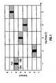
- FIG. 1shows an exemplary transmission scheme 100 for a frequency hopping communication system.
- FIG. 1shows pilot and data transmission on a frequency-time plane in which the vertical axis represents frequency and the horizontal axis represents time.
- N F8 and the eight subbands are assigned indices of 1 through 8.
- Up to eight traffic channelsmay be defined whereby each traffic channel uses one of the eight subbands in each hop period.
- a hop periodis the time duration spent on a given subband and may be defined to be equal to the duration of N H OFDM symbols, where N H ⁇ 1.
- Each traffic channelis associated with a different FH sequence.
- the FH sequences for all traffic channelsmay be generated with an FH function f ( k , T ), where k denotes the traffic channel number and T denotes system time, which is given in units of hop periods.
- N F different FH sequencesmay be generated with N F different values of k for the FH function f ( k , T ).
- the FH sequence for each traffic channelindicates the particular subband to use for that traffic channel in each hop period. For clarity, FIG. 1 shows the subbands used for one traffic channel. This traffic channel hops from subband to subband in a pseudo-random manner determined by its FH sequence.
- Np pilot symbolsare transmitted in a time division multiplexed (TDM) manner with N D data symbols (depicted as hashed boxes) in each hop period.
- TDMtime division multiplexed
- N P ⁇ 1, N D ⁇ 1, and N P + N DN H .
- Npis typically a sufficient number of pilot symbols to allow a receiver to adequately estimate the channel response in each hop period.
- FIG. 2shows a block diagram of a transmitter 200 in the frequency hopping system.
- a transmit (TX) data processor 220receives traffic data from a data source 210 and control data from a controller 250.
- an encoder 222encodes the traffic and control data in accordance with a selected coding scheme (e.g., a convolutional code, a low density parity check (LDPC) code, a Turbo code, a block code, and so on) to obtain coded data.
- a selected coding schemee.g., a convolutional code, a low density parity check (LDPC) code, a Turbo code, a block code, and so on
- the encodingincreases the reliability of the data transmission.
- a channel interleaver 224interleaves (i.e., reorders) the coded data to obtain interleaved data. The interleaving provides diversity for the coded data.
- a symbol mapping unit 226then symbol maps (i.e., modulates) the interleaved data in accordance with a selected modulation scheme to obtain data symbols.
- the selected modulation schememay be M-PSK (e.g., BPSK or QPSK), M-ary quadrature amplitude modulation (M-QAM), or some other modulation scheme.
- Symbol mapping unit 226provides a stream of data symbols to an OFDM modulator 230.
- OFDM modulator 230performs frequency hopping and OFDM modulation for the data and pilot symbols.
- a TX FH processor 232receives the data and pilot symbols and provides these symbols on the proper subband (and in the proper order) in each hop period, as indicated by an FH sequence from controller 250.
- the data and pilot symbolsdynamically hop from subband to subband in a pseudo-random manner determined by the FH sequence.
- TX FH processor 232provides N F "transmit" symbols for the N F subbands for each OFDM symbol period. These N F transmit symbols are composed of one data/pilot symbol for each subband used for data/pilot transmission and a signal value of zero for each subband not used for data/pilot transmission.
- An inverse fast Fourier transform (IFFT) unit 234receives the N F transmit symbols for each OFDM symbol period, performs an N F -point inverse fast Fourier transform on the N F transmit symbols, and provides a corresponding "transformed" symbol that contains N F time-domain chips. Each chip is a complex value to be transmitted in one chip period, where the chip rate is typically determined by the system bandwidth.
- a cyclic prefix generator 236receives the N F chips for each transformed symbol and repeats a portion of the transformed symbol to form an OFDM symbol that contains N F + N cp chips, where N cp is the number of chips being repeated.
- the repeated portionis often referred to as a cyclic prefix and is used to combat intersymbol interference (ISI) caused by a dispersive wireless channel (i.e., a wireless channel with time delay spread).
- An OFDM symbol periodis the duration of one OFDM symbol, which is N F + N cp chip periods.
- Cyclic prefix generator 236provides a stream of OFDM symbols.
- a transmitter unit (TMTR) 242conditions (e.g., converts to analog signals, filters, amplifies, and frequency upconverts) the stream of OFDM symbols to generate a modulated signal, which is transmitted from an antenna 244.
- FIG. 3shows a block diagram of a receiver 300 in the frequency hopping system.
- An antenna 312receives the modulated signal transmitted by transmitter 200 and provides the received signal to a receiver unit (RCVR) 314.
- Receiver unit 314conditions (e.g., frequency downconverts, filters, and amplifies) the received signal and further digitizes the conditioned signal to obtain a stream of samples, which is provided to an OFDM demodulator 320.
- a cyclic prefix removal unit 322receives the stream of samples, removes the cyclic prefix appended to each received OFDM symbol, and provides a corresponding received transformed symbol that contains N F samples.
- An FFT unit 324performs an N F -point FFT on the N F samples for each received transformed symbol to obtain N F received symbols for the N F subbands for that transformed symbol.
- An RX FH processor/demultiplexer 326obtains the N F received symbols for each OFDM symbol period and provides the received symbol from the proper subband as the received data/pilot symbol for that OFDM symbol period. The proper subband is determined by an FH sequence from a controller 350.
- RX FH processor 326The FH sequence used for RX FH processor 326 at receiver 300 is the same as, and synchronized to, the FH sequence used by TX FH processor 232 at transmitter 200.
- RX FH processor 326operates in unison with TX FH processor 232 and provides a stream of received data/pilot symbols from the proper subbands to a receive (RX) data processor 330.
- RX data processor 330performs iterative receiver processing on the received data and pilot symbols to obtain decoded data.
- RX data processor 330includes a channel and interference estimator 332, a detector 334, a channel deinterleaver 336, a decoder 340, and a channel interleaver 342 that operate as described below.
- RX data processor 330provides the decoded data to a data sink 348 and/or controller 350.
- Controllers 250 and 350direct operation at transmitter 200 and receiver 300, respectively.
- Memory units 252 and 352provide storage for program codes and data used by controllers 250 and 350, respectively.
- the channel magnitude a k ( m )
- is assumed to be known by the receiver and only the channel phase ⁇ k ( m ) needs to be estimated.
- the magnitude of data and pilot symbols received in each hop periodcan be averaged to obtain a reasonably accurate estimate of the channel magnitude a k ( m ) for that hop period.
- the channel gaincan be sufficiently characterized by just the channel phase. (However, the diagrams show the more general case in which the channel gain can be a complex value with unknown magnitude and phase.)
- the receivermay utilize non-iterative or iterative receiver processing to recover the transmitted data.
- the channel responseis estimated based on the received pilot symbols, and the received data symbols r k ( m ) are coherently demodulated or "detected" with the channel response estimate to obtain recovered data symbols ⁇ ( m ), which are estimates of the transmitted data symbols s k ( m ).
- the detectionis performed once for the non-iterative scheme.
- the recovered data symbolsare then deinterleaved and decoded to obtain decoded data.
- the channel estimation, detection, and decodingare performed for multiple iterations.
- the iterative schemeexploits the error correction capabilities of the coding scheme to provide improved performance. This is achieved by iteratively passing information between a channel estimator, a detector, and a decoder for multiple iterations, as described below.
- FIG. 4shows a Tanner graph 400 that graphically illustrates an iterative channel and interference estimation and decoding scheme. Iterative receiver processing is performed on a block of data symbols that, in general, can contain any number of data symbols. For clarity, the iterative receiver processing is described below for a block of N D received data symbols for one hop period.
- Tanner graph 400includes a channel and interference estimate node 410, N D detection nodes 420a through 420n for N D data symbols in the block, channel deinterleaver 336, channel interleaver 342, decoder 340, and N D estimation nodes 440a through 440n for the N D data symbols.
- Node 410couples to each detection node 420 via a respective link 412 and to each estimation node 440 via a respective link 442.
- Each of links 412 and 442carries information regarding the channel gain and interference for the data symbol associated with that link.
- Each detection node 420couples to channel deinterleaver 336 via B links 422, and each estimation node 440 couples to channel interleaver 342 via B links 436.
- Decoder 340couples to channel deinterleaver 336 via N B links 426 and to channel interleaver 342 via N B links 432.
- Each of links 422, 426, 432 and 436carries information (in the direction indicated by the link) for a code bit associated with that link.
- the information for each code bitis typically in the form of a log-likelihood ratio (LLR), which indicates the likelihood of the code bit being a one ("1") or a zero ("0").
- LLRlog-likelihood ratio
- node 410obtains estimates of the channel gain based on the received pilot symbols. Node 410 estimates only the channel phase if the channel magnitude is known. Node 410 also estimates the interference observed by the received data symbols based on the received pilot symbols. Node 410 provides "prior" information for channel phase and interference to each detection node 420 via link 412.
- Each detection node 420obtains a respective received data symbol r k ( n ) and the prior information for channel phase and interference from node 410. Each detection node 420 computes the LLR for each of the B code bits that forms its data symbol based on the received data symbol r k ( n ) and the prior information for channel phase and interference. Each detection node 420 provides B "forward" LLRs for the B code bits to channel deinterleaver 336 via links 422. Channel deinterleaver 336 deinterleaves the forward LLRs for all N B code bits in a manner complementary to the interleaving performed at the transmitter and provides deinterleaved forward LLRs to decoder 340.
- Decoder 340decodes the deinterleaved forward LLRs for the N B code bits in accordance with the coding scheme used by the transmitter. For example, decoder 340 may implement (1) a maximum a posteriori (MAP) algorithm or a soft-output Viterbi (SOV) algorithm if the transmitter uses a convolutional code or (2) a Turbo/LDPC decoder if the transmitter uses a Turbo or an LDPC code. Decoder 340 provides feedback LLRs for the N B code bits, which are updated LLRs for these bits, to channel interleaver 342 via links 432. Channel interleaver 342 interleaves the feedback LLRs in the same manner as the interleaving performed at the transmitter and provides interleaved feedback LLRs to estimation nodes 440 via links 436.
- MAPmaximum a posteriori
- SOVsoft-output Viterbi
- Decoder 340provides feedback LLRs for the N B code bits, which are updated LLRs for these bits, to channel inter
- Each estimation node 440obtains a respective received data symbol r k ( n ) and the interleaved feedback LLRs for the B code bits of that received data symbol from channel interleaver 342. Each estimation node 440 derives " a posterion " information for channel phase and interference for its data symbol based on the received data symbol r k ( n ) and the feedback LLRs and provides this a posteriori information to node 410 via link 442.
- Node 410combines the prior information for channel gain and interference and the a posteriori information for channel phase and interference from estimation nodes 440 to obtain updated information for channel gain and interference for each received data symbol. Node 410 provides the updated information for channel phase and interference to each detection node 420. The detection and decoding for the second iteration are then performed in similar manner as for the first iteration, albeit with the updated information for channel gain and interference.
- each detection node 420derives and provides "forward" information for the code bits corresponding to a respective received data symbol
- decoder 340derives and provides "feedback" information for each received data symbol.
- the forward and feedback informationis typically given in the form of LLRs, but may also be given in other forms.
- FIG. 5shows a flow diagram of a process 500 for performing iterative channel and interference estimation and decoding.
- step 510prior information for channel phase and interference is obtained based on the received pilot symbols.
- Step 510is performed by node 410 in FIG. 4 .
- the channel magnitudeis assumed to be known and only the channel phase is estimated.
- the prior information for channel phase and interferencecan be given as a joint probability distribution on channel phase ⁇ and interference power I .
- the channel phase ⁇may be quantized to L possible values and given in integer multiple of 2 ⁇ / L.
- the interference power Imay be quantized to Q possible values.
- the joint probability distribution on ⁇ and Imay be viewed as a three-dimensional (3-D) graph with the x -axis representing the channel phase ⁇ , the y -axis representing the interference power I , and the z -axis representing the joint probability of a particular channel phase ⁇ 0 and a particular interference power I 0 .given a particular received pilot symbol.
- Equation set (3)The first expression in equation set (3) is obtained based on Bayes' rule.
- the third expression in equation (3)is obtained based on the assumption that the noise and interference is a complex Gaussian random variable with zero mean and variance of I 0 .
- Equation set (3)omits a normalization factor that can be computed by applying the constraint that a probability distribution function (pdf) integrates to one over its domain.
- pdfprobability distribution function
- One joint probability distribution on ⁇ and Iis obtained for each received pilot symbol, as shown in equation set (3). If multiple received pilot symbols are available, then multiple joint probability distributions on ⁇ and I are obtained for these symbols and combined to obtain one overall or composite joint probability distribution on ⁇ and I for all received pilot symbols.
- Step 510provides one joint probability distribution on ⁇ and I for use by all N D received data symbols.
- This joint probability distributioncontains L ⁇ Q probability values for L different channel phase values and Q different interference power values, which may be viewed as a 3-D graph for probability versus ⁇ and I . This joint probability distribution represents prior information for channel phase and interference obtained based on the received pilot symbols.
- p ⁇ )may be expressed in the log-domain to simplify subsequent computation. This is similar to the use of log-likelihood ratio (LLR) to express the probability distribution of a single code bit.
- LLRlog-likelihood ratio
- the joint probability distribution on ⁇ and Iis obtained based on two variables ⁇ and I that are a priori independent
- the joint distributionis thus a product distribution of a distribution on ⁇ and a distribution on I .
- the distribution on ⁇may be assumed to be uniform.
- the distribution on Ii.e., the interference power distribution
- the interference poweris assumed to be uniform over Q values.
- the interference poweris assumed to have a standard distribution such as a Gaussian distribution or a log-normal distribution.
- the interference power distributionis obtained based on network-level computer simulation, empirical measurements, or by other means.
- step 520the forward LLRs for the B code bits of each received data symbol are computed based on the received data symbol and the joint probability distribution on ⁇ and I for that symbol.
- Step 520is performed by each detection node 420 in FIG. 4 .
- the forward LLR computation for each detection node 420may be performed in two steps.
- an a posteriori distribution on the value of the transmitted data symbol, xis computed based on the received data symbol r and the joint probability distribution on ⁇ and I .
- the a posteriori distribution on x for the received data symbolis "marginalized" to obtain the forward LLRs for the B code bits of that symbol.
- the data symbol value xis determined by the values of the B code bits and the signal constellation used to map code bits to data symbols.
- Each of the M possible values of xcorresponds to a different combination of values for the B code bits.
- the forward LLR for each code bitcan be computed as a weighted sum of the M probability values for the M possible values of x , where the weighting is determined by the distance between the data symbol in the signal constellation (or constellation symbol) and the received data symbol.
- Step 520provides B forward LLRs for the B code bits of each received data symbol, or a total of N B forward LLRs for the N B code bits of the N D data symbols being processed iteratively.
- the forward LLRsrepresent forward information provided to the decoder.
- step 530the forward LLRs for a codeword that contains the N B code bits are decoded to obtain feedback LLRs for the N B code bits.
- Step 530is performed by decoder 340 in FIG. 4 .
- the decodingmay be performed based on, for example, a MAP, SOV, or Turbo decoding algorithm, and may be performed for one or multiple iterations.
- Step 530provides N B feedback LLRs for the N B code bits, which represent feedback information provided by the decoder.
- r ⁇ Pr II 0 ⁇ Pr r
- step 550the various joint probability distributions on ⁇ and I are combined to obtain updated joint probability distributions on ⁇ and I for the N D received data symbols.
- Step 550is performed by node 410 in FIG. 4 .
- N D a posteriori joint probability distributions on ⁇ and I for the N D received data symbolsare available from step 540 and one prior joint probability distribution on ⁇ and I is available from step 510.
- These N D + 1 distributions on ⁇ and Iare used to derive N D updated distributions on ⁇ and I for the N D received data symbols.
- extrinsic informationis used to derive the updated distribution on ⁇ and I for each detection node 420.
- the extrinsic information for a data symbolexcludes information derived based on that data symbol.
- the updated distribution on ⁇ and I for each received data symbol ris thus derived based on (1) N D - 1 a posteriori distributions on ⁇ and I obtained for the other N D - 1 received data symbols and (2) the prior distribution on ⁇ and I obtained from the received pilot symbols.
- This computation (1)effectively replaces the a posteriori distribution on ⁇ and I obtained for received data symbol r with a uniform distribution and (2) assumes that the N D -1 a posteriori distributions on ⁇ and I for the other N D -1 received data symbols are obtained based on independent pieces of information.
- (6)may be extended so that any number of distributions on ⁇ and I can be combined.
- Step 550provides N D updated joint probability distributions on ⁇ and I for the N D received data symbols, which are used by detection nodes 420 to update the forward LLRs in the next iteration. Step 550 concludes one complete iteration of the joint channel and interference estimation and decoding.
- step 560a determination is made whether or not to terminate the iterative channel gain and interference estimation and decoding. This decision may be made based on one or more termination criteria. For example, a termination criterion may be as simple as a predetermined number of iterations. If the answer is 'no' for step 560, then the process returns to step 520 to update the forward LLRs for the code bits. Otherwise, the process terminates. Step 560 may be performed after step 530, so that steps 540 and 550 can be omitted for the last iteration.
- the number of values taken by channel phase and interferencedetermine the computational complexity of the various steps in FIG. 5 . Since each joint probability distribution on ⁇ and I contains L.Q probability values, the computation complexity is proportional to both L and Q, which are the number of quantized values for channel phase and interference, respectively. To maintain reasonable complexity, interference may be quantized to a low resolution with a small number of values. A technique to reduce the number of channel phase values is described below. Complexity can also be reduced by using channel phase and interference in other manners, as described below.
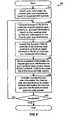
- FIG. 6shows a flow diagram of a process 600 for performing iterative channel estimation and decoding with an interference estimate.
- interferenceis estimated once and used in the iterative channel estimation and decoding process.
- the interference estimateis not iteratively updated in order to reduce complexity.
- an interference estimate and prior information for channel phaseare obtained based on the received pilot symbols (step 610).
- a joint probability distribution on ⁇ and Iis first obtained based on the received pilot symbols, as described above for step 510.
- the joint distribution on ⁇ and Iis then marginalized into a probability distribution on ⁇ and a probability distribution on I .
- a value of Iis then selected based on the distribution on I and used as the interference, estimate I est .
- the interference estimate I estmay be the largest value in the distribution on I , the I value that results in minimum mean square error for the distribution on I , and so on.
- Step 610provides a distribution on ⁇ and the interference estimate I est .
- p ⁇ ), may be expressed as: Pr ⁇⁇ 0
- ⁇⁇ 0
- II est .
- Multiple distributions on ⁇may be obtained for multiple received pilot symbols and combined to obtain one distribution on ⁇ for all received pilot symbols. Equation (7) represents one method of obtaining a distribution on ⁇ . Alternatively, the distribution resulting from marginalization can also be used directly to obtain the distribution on ⁇ .
- Step 620may be performed in two steps, similar to that described above for step 520 in FIG. 5 .
- Pr ( xx 0
- the distribution on x for each received data symbolis marginalized to obtain the forward LLRs for the B codes bits of the received data symbol.
- the forward LLRs for all N B code bitsare then decoded to obtain feedback LLRs for the code bits (step 630).
- a posteriori information for channel phaseis then obtained for each received data symbol based on the feedback LLRs for the B code bits of that symbol and the interference estimate (step 640).
- the a posteriori information for channel phase for the N D received data symbols and the prior information for channel phaseare then combined to obtain updated information for channel phase for each received data symbol (step 650).
- an updated distribution on ⁇is computed for each received data symbols based on N D - 1 a posteriori distributions on ⁇ for the other N D -1 received data symbols and the prior distribution on ⁇ derived from the received pilot symbols.
- step 660A determination is then made whether or not to terminate the iterative channel estimation and decoding (step 660). If the answer is 'no', then the process returns to step 620 to update the forward LLRs for the B code bits of each received data symbol based on the received data symbol, the updated distribution on ⁇ , and the interference estimate I est , as shown in equation (8). Otherwise, the process terminates. Again, step 660 may be performed after step 630.
- the iterative channel estimation and decoding with an interference estimatemay also be performed in other manners, and this is within the scope of the invention.
- the iterative processcan start by computing a joint probability distribution on ⁇ and I for each received data symbol with the feedback LLRs for the symbol set to zeros.
- the received data symbolcan provide information about ⁇ modulo 2 ⁇ / M even if no information is available about the transmitted data symbols. This information about ⁇ modulo 2 ⁇ / M can then yield non-trivial information about the interference.
- the joint probability distributions on ⁇ and I for the N D received data symbolsare then combined with a prior joint distribution on ⁇ and I derived from the received pilot symbols.
- the updated joint distribution on ⁇ and I for each received data symbolis then marginalized to obtain a distribution on ⁇ and a distribution on I .
- a value of Iis selected based on the distribution on I and used as the interference estimate I est .
- the distribution on ⁇ for each received data symbol and the interference estimate I estare then used to compute the forward LLRs for the received data symbol, as described above.
- the channel phase ⁇can be estimated to within a range of zero to 2 ⁇ M using non-iterative data-aided estimation.
- the technique described above for obtaining a distribution on ⁇ for each received data symbol with the feedback LLRs set to zerois an example of data-aided estimation, which is a non-iterative technique because the code output was not used for estimation.
- the channel phasecan then be quantized to M different values (instead of L values), which can greatly reduce computational complexity if M is much less than L.
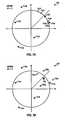
- Various methodsmay be used to estimate the channel phase based on the received data symbols. Two exemplary methods are described below.
- FIG. 7Aillustrates the estimation of the channel phase ⁇ based on the phases of the received data symbols.
- QPSK modulationis used, and five received data symbols are represented as solid dots 712a through 712e on a QPSK signal constellation 700.
- Each received data symbolhas a phase that is determined by the modulation on the data symbol, the channel phase ⁇ , and noise and interference.
- the phase of each received data symbolis first determined.
- a modulo-2 ⁇ /M operationis then performed on the phase of each received data symbol to effectively remove the modulation on the data symbol and convert the data symbol to a pilot symbol.
- the phases modulo-2 ⁇ /M for the five received data symbolsare plotted as circles 722a through 722e in signal constellation 700.
- the phases modulo- 2 ⁇ /M of the five data symbolsare then averaged to obtain a channel phase estimate ⁇ est , which is denoted by a " ⁇ " mark 730.
- FIG. 7Billustrates the estimation of the channel phase based on the complex values of the received data symbols.
- the five received data symbolsare also represented as solid dots 712a through 712e on a QPSK signal constellation 750.
- Each received data symbolis rotated by an integer multiple of 2 ⁇ /M (i.e., by 2 ⁇ il M, where i is an integer zero or greater) so that the phase of the rotated received data symbol lies within a range of zero to 2 ⁇ /M.
- Received data symbol 712ais rotated by zero degrees.
- Received data symbols 712b through 712eare rotated by the proper amounts and represented by circles 752b through 752e, respectively, in signal constellation 750.
- the five rotated received data symbolsare averaged to obtain an average received data symbol, which is represented by a " ⁇ " mark 760.
- the channel phase ⁇is estimated as the phase of the average received data symbol. This method uses both the amplitude and phase of the received data symbols to compute the channel phase estimate ⁇ est , whereas the method illustrated in FIG. 7A uses only the phase of the received data symbols.
- the channel phasemay also be estimated in other manners, and this is within the scope of the invention.
- the channel phasemay be estimated using the techniques described above for obtaining a distribution on ⁇ for each received data symbol with the feedback LLRs set to zero.
- phase of each received data symbolmay be multiplied by M and then average.
- channel phase modulo-2 ⁇ /Mcan be estimated reliably, then channel phase is known to within a range of zero to 2 ⁇ /M. The only uncertainty is which one of M possible ranges the channel phase belongs to.
- a distribution on ⁇would then contain only M values or components, and a distribution on ⁇ and I would contain only M.Q components.
- FIG. 8shows a flow diagram of a process 800 for performing iterative channel estimation and decoding with a channel phase estimate obtained from received data symbols.
- process 800does not account for interference.
- the channel phase ⁇is estimated to within a range of zero to 2 ⁇ /M based on the received data symbols (step 808).
- Step 808may be performed with the first or second channel phase estimation method described above and provides the channel phase estimate ⁇ est .
- Prior information for channel phaseis then obtained based on the received pilot symbols for M (instead of L) different values of ⁇ (step 810).
- Step 810provides a distribution on ⁇ based on the received pilot symbols for M different values of ⁇ .
- the forward LLRs for the B code bits of each received data symbolare then computed based on the received data symbol and the prior information for channel phase (step 820).
- Step 820may be performed in similar manner as described above for step 520 in FIG. 5 or step 620 in FIG. 6 .
- the forward LLRs for all N B code bitsare decoded to obtain feedback LLRs for the code bits (step 830).
- a posteriori information for channel phaseis then obtained for each received data symbol based on the feedback LLRs for the B code bits of that symbol and for M different values of ⁇ (step 840).
- the a posteriori information for channel phase for N D received data symbols and the prior information for channel phaseare combined to obtain updated information for channel phase for each received data symbol, again for M different values of ⁇ (step 850).
- step 860A determination is then made whether or not to terminate the iterative channel estimation and decoding (step 860). If the answer is 'no', then the process returns to step 820 to update the forward LLRs for the B code bits of each received data symbol based on the received data symbol and the updated distribution on ⁇ . Otherwise, the process terminates. Again, step 860 may be performed after step 830.
- FIGS. 5 , 6 and 8show three specific schemes for performing iterative receiver processing.
- the scheme in FIG. 5iteratively updates information for both channel phase and interference
- the scheme in FIG. 6iteratively updates information for channel phase and non-iteratively estimates interference
- the scheme in FIG. 8iteratively updates information for channel phase and uses phase information obtained from the received data symbols.
- Various other iterative schemesmay also be implemented, and this is within the scope of the invention.
- information for both channel phase and interferencemay be iteratively updated for a small number of iterations, and information for only channel phase may be iteratively updated thereafter.
- information for channel phasemay be obtained once, and information for interference may be iteratively updated.
- the number of values for channel phase and interferencecan be reduced in subsequent iterations. As the distribution becomes more compact, some of the points have negligibly low probabilities and can be ignores.
- the iterative channel and interference estimation and decoding schememay be viewed as iterating between decoder 340 and an a posteriori probability (APP) detector 360 (with intervening channel deinterleaver 336 and channel interleaver 342).
- APP detector 360uses the feedback information (incoming LLRs) from decoder 340 and the received pilot and data symbols (received values) to obtain the forward information (updated LLRs) for decoder 340.
- APP detector 360estimates the channel and interference based on the feedback information and received values, and the channel and interference information is reflected in the forward information provided by APP detector 360 to decoder 340.
- Other types of detector known in the artmay also be used for the APP detector.
- channel and interference estimate node 410represents one implementation of MAP detector 360.
- detection nodes 420represent one implementation of MAP detector 360.
- estimation nodes 440represent one implementation of MAP detector 360.
- MAP detector 360may also be implemented in other manners, and this is within the scope of the invention.
- RX data processor 330may implement any receiver processing scheme.
- estimator 332performs steps 510, 540 and 550, detector 334 performs step 520, and decoder 340 performs step 530.
- estimator 332performs steps 610, 640 and 650, detector 334 performs step 620, and decoder 340 performs step 630.
- estimator 332performs steps 808, 810, 840 and 850, detector 334 performs step 820, and decoder 340 performs step 830.
- Channel and interference estimator 332implements node 410 and estimation nodes 440a through 440n in FIG. 4 .
- channel and interference estimator 332obtains received pilot symbols from OFDM demodulator 320, derives prior information for channel phase and interference based on the received pilot symbols, and provides the prior information to detector 334.
- estimator 332obtains received data symbols from OFDM demodulator 320 and feedback LLRs for the B code bits of each received data symbol from channel interleaver 342, derives a posteriori information for channel gain and interference for each received data symbol, combines the a posteriori information and the prior information, and provides updated information for channel gain and interference for each received data symbol to detector 334.
- Detector 334implements detector nodes 420a through 420n in FIG. 4 .
- Detector 334obtains the received data symbols from OFDM demodulator 320 and the prior/updated information for channel phase and interference from estimator 332.
- Detector 334computes the forward LLRs for the B code bits of each received data symbol based on the prior/updated information and the received data symbol and provides the forward LLRs to channel deinterleaver 336.
- Channel deinterleaver 336deinterleaves the forward LLRs.
- Decoder 340performs decoding on the deinterleaved forward LLRs and provides feedback LLRs for the B code bits of each received data symbol to channel interleaver 342.
- Channel interleaver 342interleaves the feedback LLRs and provides interleaved feedback LLRs to estimator 332.
- information for channel phase and interferenceis represented with probability distributions.
- forward and feedback informationis represented with LLRs.
- Other representationsmay also be used for channel phase and interference and code bits, and this is within the scope of the invention.
- log domain representation, inverse probabilities, and so onmay be used.
- the computation for the various steps in FIGS. 5 , 6 , and 8is dependent on the particular representations used for the channel phase and interference and code bits.
- the received pilot symbolsmay be processed to obtain a pilot estimate, which is indicative of normalized channel observation for the pilot symbols, as shown in equation (2).
- the pilot estimatemay be obtained by (1) multiplying the received pilot symbols with the conjugated pilot symbol to remove pilot modulation and (2) maximally combining all pilot symbols received for the symbol block being recovered.
- the pilot estimateis then used to obtain a joint probability distribution on ⁇ and I for the prior information for channel phase and interference.
- the description aboveassumes that the channel magnitude is known by the receiver (i.e., determined by some means) and only the channel phase is estimated iteratively.
- the channel magnitudemay also be estimated iteratively along with the channel phase, albeit with an increase in complexity.
- the iterative receiver processing techniques described hereinmay be used for various wireless communication systems such as an OFDM-based system, a multiple-input multiple-output (MIMO) system, and so on. These techniques may also be used for the downlink (i.e., forward link) and the uplink (i.e., reverse link).
- transmitter 200is part of an access point or a base station
- receiver 300is part of a user terminal or a remote station.
- transmitter 200is part of a user terminal
- receiver 300is part of an access point.
- the iterative receiver processing techniques described hereinmay be implemented by various means. For example, these techniques may be implemented in hardware, software, or a combination thereof.
- the processing units used to perform iterative receiver processinge.g., RX data processor 330 in FIG. 3
- the processing units used to perform iterative receiver processingmay be implemented within one or more application specific integrated circuits (ASICs), digital signal processors (DSPs), digital signal processing devices (DSPDs), programmable logic devices (PLDs), field programmable gate arrays (FPGAs), processors, controllers, micro-controllers, microprocessors, other electronic units designed to perform the functions described heroin, or a combination thereof.
- ASICsapplication specific integrated circuits
- DSPsdigital signal processors
- DSPDsdigital signal processing devices
- PLDsprogrammable logic devices
- FPGAsfield programmable gate arrays
- processorscontrollers, micro-controllers, microprocessors, other electronic units designed to perform the functions described heroin, or a combination thereof
- the iterative receiver processing techniquesmay be implemented with modules (e.g., procedures, functions, and so on) that perform the functions described herein.
- the software codesmay be stored in a memory unit (e.g., memory unit 352 in FIG. 3 ) and executed by a processor (e.g., controller 350).
- the memory unitmay be implemented within the processor or external to the processor.
Landscapes
- Engineering & Computer Science (AREA)
- Computer Networks & Wireless Communication (AREA)
- Signal Processing (AREA)
- Power Engineering (AREA)
- Physics & Mathematics (AREA)
- Probability & Statistics with Applications (AREA)
- Error Detection And Correction (AREA)
- Radio Transmission System (AREA)
- Digital Transmission Methods That Use Modulated Carrier Waves (AREA)
Description
- The present invention relates generally to communication, and more specifically to techniques for recovering data in the presence of noise and interference at a receiver in a wireless communication system.
- In a wireless communication system, a transmitter typically encodes, interleaves, and modulates (i.e., symbol maps) traffic data to obtain data symbols, which are modulation symbols for data. For a coherent system, the transmitter multiplexes pilot symbols with the data symbols, processes the multiplexed pilot and data symbols to generate a modulated signal, and transmits the signal via a wireless channel. The channel distorts the transmitted signal with a channel response and further degrades the signal with noise and interference.
- A receiver receives the transmitted signal and processes the received signal to obtain received symbols. For a coherent system, the receiver typically estimates the channel response with the received pilot symbols and performs coherent demodulation/ detection of the received data symbols with the channel response estimates to obtain recovered data symbols, which are estimates of the data symbols transmitted by the transmitter. The receiver then symbol demaps, deinterleaves, and decodes the recovered data symbols to obtain decoded data, which is an estimate of the traffic data sent by the transmitter.
- In a typical coherent wireless system, the receiver processes the received pilot symbols once to obtain the channel response estimates and also performs coherent demodulation once on the received data symbols to obtain the recovered data symbols. The receiver than performs symbol demapping deinterleaving, and decoding on the recovered symbols in accordance with the coding and modulation schemes used for the traffic data. The noise and interference degrade the quality of the recovered data symbols and affect the reliability of the decoded data. Publication
WO-A-01/45296 EP-A-1 107 524 discloses an iterative channel impulse response estimation scheme where two different estimates are combined. There is therefore a need in the art for techniques to recover data in the presence of noise and interference at the receiver in a wireless communication system. - Iterative receiver processing techniques that can account for interference and provide improved performance are provided herein. These techniques may be used for various wireless communication systems and may be implemented in various manners.
- For an iterative channel and interference estimation and decoding scheme, channel gain and interference are iteratively estimated. For this scheme, prior information for channel gain and interference is initially obtained (e.g., based on received pilot symbols). Forward information for code bits corresponding to received data symbols is derived based on the received data symbols and the prior information. (Each data symbol is obtained based on B code bits, where B is dependent on the modulation scheme used for the data symbol.) The forward information is then decoded to obtain feedback information for the code bits corresponding to the received data symbols.A posteriori information for channel gain and interference for each received data symbol is derived based on the feedback information for the code bits corresponding to that received data symbol. Thea posteriori information for all received data symbols and the prior information are combined to obtain updated information for channel gain and interference for each received data symbol. The process can be repeated for any number of iterations, with the updated information for channel gain and interference being used to derive the forward information for each subsequent iteration.
- The prior information,a posteriori information, and updated information for channel gain and interference may be represented with joint probability distributions on channel gain and interference. The forward and feedback information may be represented by log-likelihood ratios (LLRs) for the code bits of the received data symbols.
- In another iterative receiver processing scheme, interference is estimated once and used in the iterative channel estimation and decoding process. This can reduce computation complexity for the various steps of the iterative process.
- For all iterative receiver processing schemes, complexity can be reduced by estimating channel magnitude non-iteratively (e.g., based on the received pilot and data symbols) and only estimating channel phase iteratively. To further reduce complexity when using an M-ary phase shift keying (M-PSK) modulation scheme, the channel phase may be estimated to within a range of 0 to 2π/ M (e.g., based on the received data symbols). In this case, the prior information,a posteriori information, and updated information for channel gain can comprise M components for M different channel phase values, where M may be much fewer than the number of components needed without the initial channel phase estimate.
- Various aspects and embodiments of the invention are described in further detail below.
- The features and nature of the present invention will become more apparent from the detailed description set forth below when taken in conjunction with the drawings in which like reference characters identify correspondingly throughout and wherein:
FIG. 1 shows a transmission scheme for a frequency hopping system;FIG. 2 shows a transmitter in the frequency hopping system;FIG. 3 shows a receiver in the frequency hopping system;FIG. 4 shows a Tanner graph that graphically illustrates iterative channel and interference estimation and decoding;FIG. 5 shows a process for performing iterative channel and interference estimation and decoding;FIG. 6 shows a process for performing iterative channel estimation and decoding with an interference estimate;FIGS. 7A and 7B illustrate two methods for estimating channel phase based on received data symbols; andFIG. 8 shows a process for performing iterative channel estimation and decoding with a channel phase estimate obtained from received data symbols.- The word "exemplay" is used herein to mean "serving as an example, instance, or illustration." Any embodiment or design described herein as "exemplary" is not necessarily to be construed as preferred or advantageous over other embodiments or designs.
- The iterative receiver processing techniques described herein may be used for various wireless communication systems that experience interference. For clarity, these techniques are described for a frequency hopping communication system in which data is transmitted on different frequency subbands in different time intervals, which are also referred to as "hop periods". With frequency hopping, a data transmission hops from subband to subband in a pseudo-random manner. This hopping provides frequency diversity and allows the data transmission to better withstand deleterious path effects such as narrow-band interference, jamming, fading, and so on.
- The subbands in a frequency hopping system may be provided by orthogonal frequency division multiplexing (OFDM), other multi-carrier modulation techniques, or some other constructs. OFDM is a modulation technique that effectively partitions the overall system bandwidth into multiple (NF) orthogonal subbands. Each subband is associated with a respective subcarrier that may be modulated with data. The subbands are also commonly referred to as tones, subcarriers, bins, and frequency channels
- A frequency hopping system may be deployed with multiple cells, where a cell typically refers to a base station and/or its coverage area. Each cell can support multiple users simultaneously. For a given cell, the data for each user in the cell may be transmitted using a specific frequency hopping (FH) sequence assigned to the user. The FH sequence indicates the specific subband to use for data transmission in each hop period. Multiple data transmissions for multiple users may be sent simultaneously using different FH sequences. These FH sequences are defined to be orthogonal to one another so that only one data transmission uses each subband in each hop period. By using orthogonal FH sequences, the data transmissions for multiple users in the same cell do not interfere with one another while enjoying the benefits of frequency diversity.
However, these users typically experience inter-cell interference from users in other cells. The interference observed by a given user can vary from hop to hop because different interfering users may be observed in different hops. FIG. 1 shows an exemplary transmission scheme 100 for a frequency hopping communication system.FIG. 1 shows pilot and data transmission on a frequency-time plane in which the vertical axis represents frequency and the horizontal axis represents time. For this example, NF = 8 and the eight subbands are assigned indices of 1 through 8. Up to eight traffic channels may be defined whereby each traffic channel uses one of the eight subbands in each hop period. A hop period is the time duration spent on a given subband and may be defined to be equal to the duration of NH OFDM symbols, where NH ≥1.- Each traffic channel is associated with a different FH sequence. The FH sequences for all traffic channels may be generated with an FH functionf (k,T), wherek denotes the traffic channel number andT denotes system time, which is given in units of hop periods. NF different FH sequences may be generated with NF different values ofk for the FH functionf (k,T). The FH sequence for each traffic channel indicates the particular subband to use for that traffic channel in each hop period. For clarity,
FIG. 1 shows the subbands used for one traffic channel. This traffic channel hops from subband to subband in a pseudo-random manner determined by its FH sequence. - For transmission scheme 100, Np pilot symbols (depicted as a solid box) are transmitted in a time division multiplexed (TDM) manner with ND data symbols (depicted as hashed boxes) in each hop period. In general, NP ≥ 1, ND ≥ 1, and NP + ND = NH. Np is typically a sufficient number of pilot symbols to allow a receiver to adequately estimate the channel response in each hop period.
FIG. 2 shows a block diagram of atransmitter 200 in the frequency hopping system. A transmit (TX)data processor 220 receives traffic data from adata source 210 and control data from acontroller 250. WithinTX data processor 220, anencoder 222 encodes the traffic and control data in accordance with a selected coding scheme (e.g., a convolutional code, a low density parity check (LDPC) code, a Turbo code, a block code, and so on) to obtain coded data. The encoding increases the reliability of the data transmission. Achannel interleaver 224 interleaves (i.e., reorders) the coded data to obtain interleaved data. The interleaving provides diversity for the coded data. Asymbol mapping unit 226 then symbol maps (i.e., modulates) the interleaved data in accordance with a selected modulation scheme to obtain data symbols. The selected modulation scheme may be M-PSK (e.g., BPSK or QPSK), M-ary quadrature amplitude modulation (M-QAM), or some other modulation scheme. The symbol mapping may be performed by (1) grouping sets of B interleaved bits to form B-bit binary values,
where B ≥ 1 and 2B = M , and (2) mapping each B-bit binary value to a point in a signal constellation corresponding to the selected modulation scheme. Each mapped signal point is a complex value and corresponds to a modulation symbol (i.e., a data symbol).Symbol mapping unit 226 provides a stream of data symbols to anOFDM modulator 230.OFDM modulator 230 performs frequency hopping and OFDM modulation for the data and pilot symbols. WithinOFDM modulator 230, aTX FH processor 232 receives the data and pilot symbols and provides these symbols on the proper subband (and in the proper order) in each hop period, as indicated by an FH sequence fromcontroller 250. The data and pilot symbols dynamically hop from subband to subband in a pseudo-random manner determined by the FH sequence.TX FH processor 232 provides NF "transmit" symbols for the NF subbands for each OFDM symbol period.
These NF transmit symbols are composed of one data/pilot symbol for each subband used for data/pilot transmission and a signal value of zero for each subband not used for data/pilot transmission.- An inverse fast Fourier transform (IFFT)
unit 234 receives the NF transmit symbols for each OFDM symbol period, performs an NF-point inverse fast Fourier transform on the NF transmit symbols, and provides a corresponding "transformed" symbol that contains NF time-domain chips. Each chip is a complex value to be transmitted in one chip period, where the chip rate is typically determined by the system bandwidth. Acyclic prefix generator 236 receives the NF chips for each transformed symbol and repeats a portion of the transformed symbol to form an OFDM symbol that contains NF + Ncp chips, where Ncp is the number of chips being repeated. The repeated portion is often referred to as a cyclic prefix and is used to combat intersymbol interference (ISI) caused by a dispersive wireless channel (i.e., a wireless channel with time delay spread). An OFDM symbol period is the duration of one OFDM symbol, which is NF + Ncp chip periods.Cyclic prefix generator 236 provides a stream of OFDM symbols. A transmitter unit (TMTR) 242 conditions (e.g., converts to analog signals, filters, amplifies, and frequency upconverts) the stream of OFDM symbols to generate a modulated signal, which is transmitted from anantenna 244. FIG. 3 shows a block diagram of areceiver 300 in the frequency hopping system. Anantenna 312 receives the modulated signal transmitted bytransmitter 200 and provides the received signal to a receiver unit (RCVR) 314.Receiver unit 314 conditions (e.g., frequency downconverts, filters, and amplifies) the received signal and further digitizes the conditioned signal to obtain a stream of samples, which is provided to anOFDM demodulator 320.- Within
OFDM demodulator 320, a cyclicprefix removal unit 322 receives the stream of samples, removes the cyclic prefix appended to each received OFDM symbol, and provides a corresponding received transformed symbol that contains NF samples. AnFFT unit 324 performs an NF-point FFT on the NF samples for each received transformed symbol to obtain NF received symbols for the NF subbands for that transformed symbol. An RX FH processor/demultiplexer 326 obtains the NF received symbols for each OFDM symbol period and provides the received symbol from the proper subband as the received data/pilot symbol for that OFDM symbol period. The proper subband is determined by an FH sequence from acontroller 350. The FH sequence used forRX FH processor 326 atreceiver 300 is the same as, and synchronized to, the FH sequence used byTX FH processor 232 attransmitter 200.RX FH processor 326 operates in unison withTX FH processor 232 and provides a stream of received data/pilot symbols from the proper subbands to a receive (RX)data processor 330. RX data processor 330 performs iterative receiver processing on the received data and pilot symbols to obtain decoded data. For the embodiment shown inFIG. 3 ,RX data processor 330 includes a channel andinterference estimator 332, adetector 334, achannel deinterleaver 336, adecoder 340, and achannel interleaver 342 that operate as described below.RX data processor 330 provides the decoded data to adata sink 348 and/orcontroller 350.Controllers transmitter 200 andreceiver 300, respectively.Memory units controllers - The model for the frequency hopping system may be expressed as:

where - sk(m) is the data or pilot symbol transmitted on subbandk in symbol periodm;
- hk(m) is the complex channel gain for subbandk in symbol periodm, which can be decomposed into a channel magnitudeak(m) and a channel phase θk(m) :
- rk(m) is the received data or pilot symbol on subbandk in symbol periodm; and
- nk(m) is the noise and interference received on subband k in symbol period m.
- For simplicity, the channel magnitudeak(m)=|hk(m)| is assumed to be known by the receiver and only the channel phase θk(m) needs to be estimated. For a constant energy modulation scheme such as M-PSK, the magnitude of data and pilot symbols received in each hop period can be averaged to obtain a reasonably accurate estimate of the channel magnitudeak(m) for that hop period. Thus, in the following description, the channel gain can be sufficiently characterized by just the channel phase. (However, the diagrams show the more general case in which the channel gain can be a complex value with unknown magnitude and phase.)
- The receiver may utilize non-iterative or iterative receiver processing to recover the transmitted data. For a non-iterative scheme, the channel response is estimated based on the received pilot symbols, and the received data symbolsrk(m) are coherently demodulated or "detected" with the channel response estimate to obtain recovered data symbolsŝ(m), which are estimates of the transmitted data symbolssk(m). The detection is performed once for the non-iterative scheme. The recovered data symbols are then deinterleaved and decoded to obtain decoded data. For an iterative scheme, the channel estimation, detection, and decoding are performed for multiple iterations. The iterative scheme exploits the error correction capabilities of the coding scheme to provide improved performance. This is achieved by iteratively passing information between a channel estimator, a detector, and a decoder for multiple iterations, as described below.
FIG. 4 shows aTanner graph 400 that graphically illustrates an iterative channel and interference estimation and decoding scheme. Iterative receiver processing is performed on a block of data symbols that, in general, can contain any number of data symbols. For clarity, the iterative receiver processing is described below for a block of ND received data symbols for one hop period. The ND received data symbols are formed by NB code bits, where NH = B· ND.Tanner graph 400 includes a channel andinterference estimate node 410, ND detection nodes 420a through 420n for ND data symbols in the block,channel deinterleaver 336,channel interleaver 342,decoder 340, and ND estimation nodes 440a through 440n for the ND data symbols.Node 410 couples to each detection node 420 via arespective link 412 and to each estimation node 440 via arespective link 442. Each oflinks deinterleaver 336 via B links 422, and each estimation node 440 couples to channelinterleaver 342 via B links 436.Decoder 340 couples to channeldeinterleaver 336 via NB links 426 and to channelinterleaver 342 via NB links 432.
Each oflinks - For the first iteration,
node 410 obtains estimates of the channel gain based on the received pilot symbols.Node 410 estimates only the channel phase if the channel magnitude is known.Node 410 also estimates the interference observed by the received data symbols based on the received pilot symbols.Node 410 provides "prior" information for channel phase and interference to each detection node 420 vialink 412. - Each detection node 420 obtains a respective received data symbolrk(n) and the prior information for channel phase and interference from
node 410. Each detection node 420 computes the LLR for each of the B code bits that forms its data symbol based on the received data symbolrk(n) and the prior information for channel phase and interference. Each detection node 420 provides B "forward" LLRs for the B code bits tochannel deinterleaver 336 vialinks 422.Channel deinterleaver 336 deinterleaves the forward LLRs for all NB code bits in a manner complementary to the interleaving performed at the transmitter and provides deinterleaved forward LLRs todecoder 340. Decoder 340 decodes the deinterleaved forward LLRs for the NB code bits in accordance with the coding scheme used by the transmitter. For example,decoder 340 may implement (1) a maximuma posteriori (MAP) algorithm or a soft-output Viterbi (SOV) algorithm if the transmitter uses a convolutional code or (2) a Turbo/LDPC decoder if the transmitter uses a Turbo or an LDPC code.Decoder 340 provides feedback LLRs for the NB code bits, which are updated LLRs for these bits, to channelinterleaver 342 vialinks 432.Channel interleaver 342 interleaves the feedback LLRs in the same manner as the interleaving performed at the transmitter and provides interleaved feedback LLRs to estimation nodes 440 vialinks 436.- Each estimation node 440 obtains a respective received data symbolrk(n) and the interleaved feedback LLRs for the B code bits of that received data symbol from
channel interleaver 342. Each estimation node 440 derives "a posterion" information for channel phase and interference for its data symbol based on the received data symbolrk(n) and the feedback LLRs and provides thisa posteriori information tonode 410 vialink 442. Node 410 combines the prior information for channel gain and interference and thea posteriori information for channel phase and interference from estimation nodes 440 to obtain updated information for channel gain and interference for each received data symbol.Node 410 provides the updated information for channel phase and interference to each detection node 420. The detection and decoding for the second iteration are then performed in similar manner as for the first iteration, albeit with the updated information for channel gain and interference.- In
FIG. 4 , each detection node 420 derives and provides "forward" information for the code bits corresponding to a respective received data symbol, anddecoder 340 derives and provides "feedback" information for each received data symbol. The forward and feedback information is typically given in the form of LLRs, but may also be given in other forms. FIG. 5 shows a flow diagram of aprocess 500 for performing iterative channel and interference estimation and decoding.- In
step 510, prior information for channel phase and interference is obtained based on the received pilot symbols. Step 510 is performed bynode 410 inFIG. 4 . Again, the channel magnitude is assumed to be known and only the channel phase is estimated. The normalized channel observation for the pilot symbols may be expressed as:
where the channel gain a and channel phase θ are assumed to be constant for all ND data symbols in the block and the noise and interference n is assumed to be a complex Gaussian random variable with zero mean and a variance ofN0. - The prior information for channel phase and interference can be given as a joint probability distribution on channel phase θ and interference powerI. For simplicity, the channel phase θ may be quantized to L possible values and given in integer multiple of 2π / L. Similarly, the interference powerI may be quantized to Q possible values. The joint probability distribution on θ andI may be viewed as a three-dimensional (3-D) graph with thex-axis representing the channel phase θ, they-axis representing the interference powerI, and thez-axis representing the joint probability of a particular channel phase θ0 and a particular interference powerI0 .given a particular received pilot symbol. The joint probability distribution on θ andI may be expressed as:

where - p̃ is the received pilot symbol andp is the actual pilot symbol;
- Pr (θ = θ0,I = θ0|p̃) is the joint probability distribution on θ andI, which gives the probability of the channel phase being θ0 and the interference power beingI0 given the received pilot symbolp̃ ;
- Pr (θ = θ0,I =I0) is ana priori joint probability distribution on θ andI, which gives the probability of the channel phase being θ0 and the interference power beingI0 ;
- Pr(p̃|θ=θ0,I=I0) is a probability distribution (obtained based on a communication channel model, e.g., Gaussian) that gives the probability of obtaining the received pilot symbolp̃ for a given channel phase θ0 and interference power I0 ;
- Pr(p̃) is the probability of obtaining a given value ofp̃ ; and
- Pr (I =I0) is ana priori probability distribution onI, which gives the probability of the interference power beingI0.
- The first expression in equation set (3) is obtained based on Bayes' rule.
The second expression in equation set (3) is obtained with the assumption that different values of channel phase θ area priori equiprobable, so that Pr (θ = θ0) is a constant and can be omitted. The third expression in equation (3) is obtained based on the assumption that the noise and interference is a complex Gaussian random variable with zero mean and variance ofI0. Equation set (3) omits a normalization factor that can be computed by applying the constraint that a probability distribution function (pdf) integrates to one over its domain. - One joint probability distribution on θ andI is obtained for each received pilot symbol, as shown in equation set (3). If multiple received pilot symbols are available, then multiple joint probability distributions on θ andI are obtained for these symbols and combined to obtain one overall or composite joint probability distribution on θ andI for all received pilot symbols. Step 510 provides one joint probability distribution on θ andI for use by all ND received data symbols. This joint probability distribution contains L·Q probability values for L different channel phase values and Q different interference power values, which may be viewed as a 3-D graph for probability versus θ andI. This joint probability distribution represents prior information for channel phase and interference obtained based on the received pilot symbols.
- The probabilities for the oint distribution Pr(θ=θ0,I=I0|p̃) may be expressed in the log-domain to simplify subsequent computation. This is similar to the use of log-likelihood ratio (LLR) to express the probability distribution of a single code bit. The use of log-domain representation for probabilities avoids the need to compute the outer exponential in the third expression of equation set (3).
- The joint probability distribution on θ andI is obtained based on two variables θ andI that area priori independent The joint distribution is thus a product distribution of a distribution on θ and a distribution onI. The distribution on θ may be assumed to be uniform. The distribution onI (i.e., the interference power distribution) may be derived in various manners. In one embodiment, the interference power is assumed to be uniform over Q values. In another embodiment, the interference power is assumed to have a standard distribution such as a Gaussian distribution or a log-normal distribution. In yet another embodiment, the interference power distribution is obtained based on network-level computer simulation, empirical measurements, or by other means.
- In
step 520, the forward LLRs for the B code bits of each received data symbol are computed based on the received data symbol and the joint probability distribution on θ andI for that symbol. Step 520 is performed by each detection node 420 inFIG. 4 . The forward LLR computation for each detection node 420 may be performed in two steps. In the first step, ana posteriori distribution on the value of the transmitted data symbol,x, is computed based on the received data symbolr and the joint probability distribution on θ andI. A data symbol can take on one of M = 2B possible values. Thisa posteriori distribution indicates the probability for each of the M possible values ofx given the received data symbolr and the joint probability distribution on θ andI. Thea posteriori distribution onx givenr may be expressed as:
where - x is the data symbol value and can take on M possible values;
- Pr (x =x0 |r) is thea posteriori distribution onx givenr, which gives the probability of the data symbol value beingx0 given the received data symbolr,
- Pr(r|x=x0) is a distribution that gives the probability of obtaining received data symbol r given the data symbol value beingx0 ;
- Pr(θ=θi,I=Ij) is the joint distribution on θ andI from the channel and interference estimation; and
- Pr(r |x =x0, θ = θi,I =Ij) is a complex Gaussian distribution with a mean ofx0aejθi and variance ofIj.
Thea posteriori distribution onx givenr, Pr (x =x0 |r), may be viewed as a 2-D graph that contains M probability values for M values ofx corresponding to the received data symbolr. - In the second step for computing the forward LLRs, thea posteriori distribution onx for the received data symbol is "marginalized" to obtain the forward LLRs for the B code bits of that symbol. The data symbol valuex is determined by the values of the B code bits and the signal constellation used to map code bits to data symbols. Each of the M possible values ofx corresponds to a different combination of values for the B code bits. The forward LLR for each code bit can be computed as a weighted sum of the M probability values for the M possible values ofx, where the weighting is determined by the distance between the data symbol in the signal constellation (or constellation symbol) and the received data symbol. Step 520 provides B forward LLRs for the B code bits of each received data symbol, or a total of NB forward LLRs for the NB code bits of the ND data symbols being processed iteratively. The forward LLRs represent forward information provided to the decoder.
- In
step 530, the forward LLRs for a codeword that contains the NB code bits are decoded to obtain feedback LLRs for the NB code bits. Step 530 is performed bydecoder 340 inFIG. 4 . The decoding may be performed based on, for example, a MAP, SOV, or Turbo decoding algorithm, and may be performed for one or multiple iterations. Step 530 provides NB feedback LLRs for the NB code bits, which represent feedback information provided by the decoder. - In
step 540, ana posteriori joint probability distribution on θ andI is computed for each received data symbol based on the feedback LLRs for the B code bits of that data symbol, as follows:
where - Pr (θ = θ0,I = I0 |r) is thea posteriori joint probability distribution on θ and I, which provides the probability of the channel phase being θ0 and the interference power beingI0 given the received data symbolr;
- Pr (x =xi) is a product distribution on the data symbol valuex, which can be obtained from the feedback LLRs for the B code bits of the received data symbolr; and
- Pr(r|x=xi,θ=θ0,I=I0) is a complex Gaussian random distribution with a mean ofxi · a · ejθ
o and variance ofI0. - In
step 550, the various joint probability distributions on θ andI are combined to obtain updated joint probability distributions on θ andI for the ND received data symbols. Step 550 is performed bynode 410 inFIG. 4 . Forstep 550, NDa posteriori joint probability distributions on θ andI for the ND received data symbols are available fromstep 540 and one prior joint probability distribution on θ andI is available fromstep 510. These ND + 1 distributions on θ andI are used to derive ND updated distributions on θ andI for the ND received data symbols. To avoid positive feedback, only extrinsic information is used to derive the updated distribution on θ andI for each detection node 420. The extrinsic information for a data symbol excludes information derived based on that data symbol. The updated distribution on θ andI for each received data symbolr is thus derived based on (1) ND - 1a posteriori distributions on θ andI obtained for the other ND - 1 received data symbols and (2) the prior distribution on θ andI obtained from the received pilot symbols. This computation (1) effectively replaces thea posteriori distribution on θ andI obtained for received data symbolr with a uniform distribution and (2) assumes that the ND -1a posteriori distributions on θ andI for the other ND -1 received data symbols are obtained based on independent pieces of information. - As an example, suppose that two distributions on θ andI, namely Pr(θ=θ0,I=I0,|α) and Pr(θ=θ0,I=I0|β), are to be combined, where α and β are independent random variables when conditioned on θ andI. The composite distribution may be expressed as:

The computation in equation (6) may be extended so that any number of distributions on θ andI can be combined. Step 550 provides ND updated joint probability distributions on θ andI for the ND received data symbols, which are used by detection nodes 420 to update the forward LLRs in the next iteration. Step 550 concludes one complete iteration of the joint channel and interference estimation and decoding. - In
step 560, a determination is made whether or not to terminate the iterative channel gain and interference estimation and decoding. This decision may be made based on one or more termination criteria. For example, a termination criterion may be as simple as a predetermined number of iterations. If the answer is 'no' forstep 560, then the process returns to step 520 to update the forward LLRs for the code bits. Otherwise, the process terminates. Step 560 may be performed afterstep 530, so thatsteps - For simplicity, the computation of probability distribution is explicitly shown only for equation (1) and is omitted for all other equations. The computation of the various probability distributions described herein is known in the art.
- The number of values taken by channel phase and interference determine the computational complexity of the various steps in
FIG. 5 . Since each joint probability distribution on θ andI contains L.Q probability values, the computation complexity is proportional to both L and Q, which are the number of quantized values for channel phase and interference, respectively. To maintain reasonable complexity, interference may be quantized to a low resolution with a small number of values. A technique to reduce the number of channel phase values is described below. Complexity can also be reduced by using channel phase and interference in other manners, as described below. FIG. 6 shows a flow diagram of aprocess 600 for performing iterative channel estimation and decoding with an interference estimate. Forprocess 600, interference is estimated once and used in the iterative channel estimation and decoding process. The interference estimate is not iteratively updated in order to reduce complexity.- Initially, an interference estimate and prior information for channel phase are obtained based on the received pilot symbols (step 610). For
step 610, a joint probability distribution on θ andI is first obtained based on the received pilot symbols, as described above forstep 510. The joint distribution on θ andI is then marginalized into a probability distribution on θ and a probability distribution onI. A value ofI is then selected based on the distribution onI and used as the interference, estimateIest. The interference estimateIest may be the largest value in the distribution onI, theI value that results in minimum mean square error for the distribution onI, and so on. Step 610 provides a distribution on θ and the interference estimateIest. The distribution on θ, Pr(θ = θ0 |p̃), may be expressed as:
Multiple distributions on θ may be obtained for multiple received pilot symbols and combined to obtain one distribution on θ for all received pilot symbols. Equation (7) represents one method of obtaining a distribution on θ. Alternatively, the distribution resulting from marginalization can also be used directly to obtain the distribution on θ. - The forward LLRs for the B code bits of each received data symbol are then computed based on the received data symbol, the prior information for channel phase, and the interference estimate (step 620). Step 620 may be performed in two steps, similar to that described above for
step 520 inFIG. 5 . In the first step, ana posteriori distribution onx givenr, Pr (x =x0|r), is computed as follows:
In the second step, the distribution on x for each received data symbol is marginalized to obtain the forward LLRs for the B codes bits of the received data symbol. - The forward LLRs for all NB code bits are then decoded to obtain feedback LLRs for the code bits (step 630).A posteriori information for channel phase is then obtained for each received data symbol based on the feedback LLRs for the B code bits of that symbol and the interference estimate (step 640). Thea posteriori distribution on θ for each received data symbol may be expressed as:

- Thea posteriori information for channel phase for the ND received data symbols and the prior information for channel phase are then combined to obtain updated information for channel phase for each received data symbol (step 650). In particular, an updated distribution on θ is computed for each received data symbols based on ND - 1a posteriori distributions on θ for the other ND -1 received data symbols and the prior distribution on θ derived from the received pilot symbols.
- A determination is then made whether or not to terminate the iterative channel estimation and decoding (step 660). If the answer is 'no', then the process returns to step 620 to update the forward LLRs for the B code bits of each received data symbol based on the received data symbol, the updated distribution on θ, and the interference estimateIest, as shown in equation (8). Otherwise, the process terminates. Again,
step 660 may be performed afterstep 630. - The iterative channel estimation and decoding with an interference estimate may also be performed in other manners, and this is within the scope of the invention. For example, the iterative process can start by computing a joint probability distribution on θ andI for each received data symbol with the feedback LLRs for the symbol set to zeros. The received data symbol can provide information about θ modulo 2π / M even if no information is available about the transmitted data symbols. This information about θ modulo 2π / M can then yield non-trivial information about the interference. The joint probability distributions on θ andI for the ND received data symbols are then combined with a prior joint distribution on θ andI derived from the received pilot symbols. The updated joint distribution on θ andI for each received data symbol is then marginalized to obtain a distribution on θ and a distribution onI. A value ofI is selected based on the distribution onI and used as the interference estimateIest. The distribution on θ for each received data symbol and the interference estimateIest are then used to compute the forward LLRs for the received data symbol, as described above.
- As noted above, one factor that affects the computational complexity of a scheme that iteratively updates channel phase information is the number of values to which the channel phase θ is quantized (i.e., the value for L). For M-PSK modulation, the channel phase θ can be estimated to within a range of zero to 2π M using non-iterative data-aided estimation. The technique described above for obtaining a distribution on θ for each received data symbol with the feedback LLRs set to zero is an example of data-aided estimation, which is a non-iterative technique because the code output was not used for estimation. The channel phase can then be quantized to M different values (instead of L values), which can greatly reduce computational complexity if M is much less than L. Various methods may be used to estimate the channel phase based on the received data symbols. Two exemplary methods are described below.
FIG. 7A illustrates the estimation of the channel phase θbased on the phases of the received data symbols. In this example, QPSK modulation is used, and five received data symbols are represented assolid dots 712a through 712e on aQPSK signal constellation 700. Each received data symbol has a phase that is determined by the modulation on the data symbol, the channel phase θ, and noise and interference. For this method, the phase of each received data symbol is first determined. A modulo-2π/M operation is then performed on the phase of each received data symbol to effectively remove the modulation on the data symbol and convert the data symbol to a pilot symbol. The phases modulo-2π/M for the five received data symbols are plotted ascircles 722a through 722e insignal constellation 700. The phases modulo- 2π/M of the five data symbols are then averaged to obtain a channel phase estimate θest, which is denoted by a "×"mark 730.FIG. 7B illustrates the estimation of the channel phase based on the complex values of the received data symbols. For this method, the five received data symbols are also represented assolid dots 712a through 712e on aQPSK signal constellation 750. Each received data symbol is rotated by an integer multiple of 2π/M (i.e., by 2π·ilM, wherei is an integer zero or greater) so that the phase of the rotated received data symbol lies within a range of zero to 2π/M. Receiveddata symbol 712a is rotated by zero degrees.Received data symbols 712b through 712e are rotated by the proper amounts and represented bycircles 752b through 752e, respectively, insignal constellation 750. The five rotated received data symbols are averaged to obtain an average received data symbol, which is represented by a "×"mark 760. The channel phase θ is estimated as the phase of the average received data symbol. This method uses both the amplitude and phase of the received data symbols to compute the channel phase estimate θest, whereas the method illustrated inFIG. 7A uses only the phase of the received data symbols.- The channel phase may also be estimated in other manners, and this is within the scope of the invention. For example, the channel phase may be estimated using the techniques described above for obtaining a distribution on θ for each received data symbol with the feedback LLRs set to zero. As another example, phase of each received data symbol may be multiplied by M and then average.
- If the channel phase modulo-2π/M can be estimated reliably, then channel phase is known to within a range of zero to 2π/M. The only uncertainty is which one of M possible ranges the channel phase belongs to. An iterative scheme can then operate on M different values for channel phase, i.e., {θest, θest + θM, θest + 2θM, ... θest + (M-1)·θM}, where θM = 2π/M, instead of L different values, where L is typically much larger than M. A distribution on θ would then contain only M values or components, and a distribution on θ andI would contain only M.Q components. The computations for the forward LLRs and feedback LLRs are greatly simplified because of the fewer number of components to evaluate. For example, if the channel phase is quantized to L = 8 M values, then the estimation of the channel phase to modulo-2π/M reduces the channel estimation complexity by a factor of eight The estimation of the channel phase (e.g., with received data symbols) may be used for any iterative receiver processing scheme.
FIG. 8 shows a flow diagram of aprocess 800 for performing iterative channel estimation and decoding with a channel phase estimate obtained from received data symbols. For simplicity,process 800 does not account for interference.- Initially, the channel phase θ is estimated to within a range of zero to 2π/M based on the received data symbols (step 808). Step 808 may be performed with the first or second channel phase estimation method described above and provides the channel phase estimate θest. Prior information for channel phase is then obtained based on the received pilot symbols for M (instead of L) different values of θ (step 810). Step 810 provides a distribution on θ based on the received pilot symbols for M different values of θ.
- The forward LLRs for the B code bits of each received data symbol are then computed based on the received data symbol and the prior information for channel phase (step 820). Step 820 may be performed in similar manner as described above for
step 520 inFIG. 5 or step 620 inFIG. 6 . The forward LLRs for all NB code bits are decoded to obtain feedback LLRs for the code bits (step 830).A posteriori information for channel phase is then obtained for each received data symbol based on the feedback LLRs for the B code bits of that symbol and for M different values of θ (step 840). Thea posteriori information for channel phase for ND received data symbols and the prior information for channel phase are combined to obtain updated information for channel phase for each received data symbol, again for M different values of θ (step 850). - A determination is then made whether or not to terminate the iterative channel estimation and decoding (step 860). If the answer is 'no', then the process returns to step 820 to update the forward LLRs for the B code bits of each received data symbol based on the received data symbol and the updated distribution on θ.
Otherwise, the process terminates. Again,step 860 may be performed afterstep 830. FIGS. 5 ,6 and8 show three specific schemes for performing iterative receiver processing. The scheme inFIG. 5 iteratively updates information for both channel phase and interference, the scheme inFIG. 6 iteratively updates information for channel phase and non-iteratively estimates interference, and the scheme inFIG. 8 iteratively updates information for channel phase and uses phase information obtained from the received data symbols. Various other iterative schemes may also be implemented, and this is within the scope of the invention. For example, information for both channel phase and interference may be iteratively updated for a small number of iterations, and information for only channel phase may be iteratively updated thereafter. As another example, information for channel phase may be obtained once, and information for interference may be iteratively updated. As yet another example, the number of values for channel phase and interference can be reduced in subsequent iterations. As the distribution becomes more compact, some of the points have negligibly low probabilities and can be ignores.- Referring back to
FIGS. 3 and4 , the iterative channel and interference estimation and decoding scheme may be viewed as iterating betweendecoder 340 and ana posteriori probability (APP) detector 360 (with interveningchannel deinterleaver 336 and channel interleaver 342). (An APP detector returns a distribution on a bit (i.e., an LLR) whereas a MAP detector returns the most likely value of the bit (i.e., 0 or 1).APP detector 360 uses the feedback information (incoming LLRs) fromdecoder 340 and the received pilot and data symbols (received values) to obtain the forward information (updated LLRs) fordecoder 340.APP detector 360 estimates the channel and interference based on the feedback information and received values, and the channel and interference information is reflected in the forward information provided byAPP detector 360 todecoder 340. Other types of detector known in the art may also be used for the APP detector. - In
Tanner graph 400, channel andinterference estimate node 410, detection nodes 420, and estimation nodes 440 represent one implementation ofMAP detector 360.MAP detector 360 may also be implemented in other manners, and this is within the scope of the invention. - Referring back to
FIG. 3 ,RX data processor 330 may implement any receiver processing scheme. For the scheme shown inFIG. 5 ,estimator 332 performssteps detector 334 performsstep 520, anddecoder 340 performsstep 530. For the scheme shown inFIG. 6 ,estimator 332 performssteps detector 334 performsstep 620, anddecoder 340 performsstep 630. For the scheme shown inFIG. 8 ,estimator 332 performssteps detector 334 performsstep 820, anddecoder 340 performsstep 830. - For clarity, the processing by
RX data processor 330 for the scheme shown inFIGS. 4 and5 is described below. Channel andinterference estimator 332 implementsnode 410 andestimation nodes 440a through 440n inFIG. 4 . For the first iteration, channel andinterference estimator 332 obtains received pilot symbols fromOFDM demodulator 320, derives prior information for channel phase and interference based on the received pilot symbols, and provides the prior information todetector 334.
For each subsequent iteration,estimator 332 obtains received data symbols fromOFDM demodulator 320 and feedback LLRs for the B code bits of each received data symbol fromchannel interleaver 342, derivesa posteriori information for channel gain and interference for each received data symbol, combines thea posteriori information and the prior information, and provides updated information for channel gain and interference for each received data symbol todetector 334. Detector 334 implementsdetector nodes 420a through 420n inFIG. 4 .Detector 334 obtains the received data symbols fromOFDM demodulator 320 and the prior/updated information for channel phase and interference fromestimator 332.Detector 334 computes the forward LLRs for the B code bits of each received data symbol based on the prior/updated information and the received data symbol and provides the forward LLRs tochannel deinterleaver 336.Channel deinterleaver 336 deinterleaves the forward LLRs.Decoder 340 performs decoding on the deinterleaved forward LLRs and provides feedback LLRs for the B code bits of each received data symbol tochannel interleaver 342.Channel interleaver 342 interleaves the feedback LLRs and provides interleaved feedback LLRs toestimator 332.- In the description above, information for channel phase and interference is represented with probability distributions. Furthermore, forward and feedback information is represented with LLRs. Other representations may also be used for channel phase and interference and code bits, and this is within the scope of the invention. For example, log domain representation, inverse probabilities, and so on may be used. The computation for the various steps in
FIGS. 5 ,6 , and8 is dependent on the particular representations used for the channel phase and interference and code bits. - For clarity, the computation for each of the steps in
FIG. 5 is specifically described. Each step may also derive its information in other manners, and this is within the scope of the invention. As an example, forstep 510 inFIG. 5 , the received pilot symbols may be processed to obtain a pilot estimate, which is indicative of normalized channel observation for the pilot symbols, as shown in equation (2). The pilot estimate may be obtained by (1) multiplying the received pilot symbols with the conjugated pilot symbol to remove pilot modulation and (2) maximally combining all pilot symbols received for the symbol block being recovered. The pilot estimate is then used to obtain a joint probability distribution on θ andI for the prior information for channel phase and interference. - For simplicity, the description above assumes that the channel magnitude is known by the receiver (i.e., determined by some means) and only the channel phase is estimated iteratively. The channel magnitude may also be estimated iteratively along with the channel phase, albeit with an increase in complexity.
- The iterative receiver processing techniques described herein may be used for various wireless communication systems such as an OFDM-based system, a multiple-input multiple-output (MIMO) system, and so on. These techniques may also be used for the downlink (i.e., forward link) and the uplink (i.e., reverse link). For the downlink,
transmitter 200 is part of an access point or a base station, andreceiver 300 is part of a user terminal or a remote station. For the uplink,transmitter 200 is part of a user terminal, andreceiver 300 is part of an access point. - The iterative receiver processing techniques described herein may be implemented by various means. For example, these techniques may be implemented in hardware, software, or a combination thereof. For a hardware implementation, the processing units used to perform iterative receiver processing (e.g.,
RX data processor 330 inFIG. 3 ) may be implemented within one or more application specific integrated circuits (ASICs), digital signal processors (DSPs), digital signal processing devices (DSPDs), programmable logic devices (PLDs), field programmable gate arrays (FPGAs), processors, controllers, micro-controllers, microprocessors, other electronic units designed to perform the functions described heroin, or a combination thereof. - For a software implementation, the iterative receiver processing techniques may be implemented with modules (e.g., procedures, functions, and so on) that perform the functions described herein. The software codes may be stored in a memory unit (e.g.,
memory unit 352 inFIG. 3 ) and executed by a processor (e.g., controller 350). The memory unit may be implemented within the processor or external to the processor. - The previous description of the disclosed embodiments is provided to enable any person skilled in the art to make or use the present invention. Various modifications to these embodiments will be readily apparent to those skilled in the art, and the generic principles defined herein may be applied to other embodiments without departing from the scope of the invention. Thus, the present invention is not intended to be limited to the embodiments shown herein but is to be accorded the widest scope consistent with the principles and novel features disclosed herein.


Claims (41)
- A method of recovering data in a wireless communication system, comprising:obtaining (510) first information for channel gain and interference;deriving first information (520) for code bits corresponding to received data symbols based on the received data symbols and the first information for channel gain and interference;decoding (530) the first information for code bits to obtain feedback information for the code bits corresponding to the received data symbols;deriving (540) second information for channel gain and interference for each of the received data symbols based on the feedback information for the code bits corresponding to the received data symbol; andcombining (550) the second information for channel gain and interference for the received data symbols and the first information for channel gain and interference to obtain updated information for channel gain and interference for each of the received data symbols;characterized by deriving the second information for channel gain and interference for each of the received data symbols excludes information derived based onthat received data symbol.
- The method of claim 1, further comprising:repeating the deriving first information for at least one additional iteration based on the updated information for channel gain and interference.
- The method of claim 1, further comprising:repeating (560) the deriving first information, decoding the first information, deriving second information, and combining the second information and the first information for a plurality of iterations, and wherein the first information for code bits is derived based on the first information for channel gain and interference for first iteration and based on the updated information for channel gain and interference for each subsequent iteration.
- The method of claim 1, wherein the first and feedback information for the code bits corresponding to each received data symbol is represented by loglikelihood ratios (LLRs) for the code bits.
- The method of claim 1, wherein the first information for channel gain and interference, the second information for channel gain and interference for each received data symbol, and the updated information for channel gain and interference for each received data symbol are each represented by a joint probability distribution on channel gain and interference.
- The method of claim 5, wherein each joint probability distribution is quantized to a predetermined number of values to reduce complexity.
- The method of claim 6, wherein the predetermined number of values are selected based on points with maximum probability in the joint probability distribution.
- The method of claim 6, wherein the predetermined number of values is reduced for each subsequent iteration of the deriving first information, decoding the first information, deriving second information, and combining the second information and the first information for channel gain and interference.
- The method of claim 1, wherein the updated information for channel gain and interference for each received data symbol is obtained by combining the first information for channel gain and interference and the second information for channel gain and interference for other ones of the received data symbols.
- The method of claim 1, wherein the first information for channel gain and interference is obtained based on received pilot symbols.
- The method of claim 1 wherein the obtaining first information for channel gain and interference is based on received pilot symbols;
the deriving first information for code bits comprises computing forward loglikelihood ratios (LLRs) for code bits corresponding to received data symbols based on the received data symbols and the first information for channel gain and interference;
the decoding the first information for code bits comprises decoding the forward LLRs for the code bits to obtain feedback LLRs for the code bits;
the deriving the second information for channel gain and interference for each of the received data symbols is based on the feedback LLRs for the code bits of the received data symbol. - The method of claim 1, wherein the channel gain is composed of channel magnitude and channel phase, wherein the channel magnitude is determined non-iteratively, and wherein first information, second information, and updated information are obtained for channel phase and interference.
- The method of claim 12, wherein the obtaining first information for channel phase and interference includes
computing a joint probability distribution on channel phase and interference for each of at least one received pilot symbol, and
combining at least one joint probability distribution on channel phase and interference for the at least one received pilot symbol to obtain a composite joint probability distribution on channel phase and interference, wherein the first information for channel phase and interference comprises the composite joint probability distribution on channel phase and interference. - The method of claim 11, wherein the computing forward LLRs for each of the received data symbols includes
computing a probability distribution on data symbol value x based on the received data symbol and a joint probability distribution on channel phase and interference for the received data symbol, and
deriving the forward LLRs for code bits of the received data symbol based on the probability distribution on x. - The method of claim 11, wherein the decoding is performed with a maximuma posteriori (MAP) decoder or a soft-output Viterbi (SOV) decoder.
- The method of claim 11, wherein the decoding is performed with one or more iterations of a Turbo decoder or a low density parity check (LDPC) decoder.
- An apparatus in a wireless communication system, comprising:means (410) for obtaining first information for channel gain and interference;means for deriving (420) first information for code bits corresponding to received data symbols based on the received data symbols and the first information for channel gain and interference;means for decoding (340) the first information for code bits to obtain feedback information for the code bits corresponding to the received data symbols;means (440) for deriving second information for channel gain and interference for each of the received data symbols based on the feedback information for the code bits corresponding to the received data symbol; andmeans for combining the second information for channel gain and interference for the received data symbols and the first information for channel gain and interference to obtain updated information for channel gain and interference for each of the received data symbols;characterized by the means for deriving second information for channel gain and interference for each of the received data symbols comprises means for excluding information derived based onthat received data symbol.
- The apparatus of claim 17, further comprising:means for repeating the deriving first information for channel gain and interference, decoding the first information for code bits, deriving second information, and combining the second information and the first information for channel gain and interference for a plurality of iterations, and wherein the first information for code bits is derived based on the first information for channel gain and interference for first iteration and based on the updated information for channel gain and interference for each subsequent iteration.
- The apparatus of claim 17, wherein means for deriving and the means for decoding are operative to exchange first and feedback information for code bits for a plurality of iterations.
- The apparatus of claim 17, wherein the means for obtaining second information for channel gain and interference is ana posteriori probability (APP) detector.
- The apparatus of claim 17, wherein the means for combining is adapted to use the received data symbols and received pilot symbols to derive the updated information for channel gain and interference.
- The apparatus of claim 17, wherein the first and feedback information for code bits is represented by log-likelihood ratios (LLRs) for the code bits corresponding to the received data symbols.
- The apparatus of claim 17 wherein
the means for deriving first information for code bits comprises means for computing forward log-likelihood ratios (LLRs) for code bits corresponding to received data symbols based on the received data symbols and the first information for channel gain and interference;
the means for decoding the first information for code bits comprises means for decoding the forward LLRs for the code bits to obtain feedback LLRs for the code bits;
the means for deriving the second information for channel gain and interference for each of the received data symbols is based on the feedback LLRs for the code bits of the received data symbol. - The apparatus of claim 17, wherein the channel gain is composed of channel magnitude and channel phase, wherein the channel magnitude is determined non-iteratively, and wherein first information, the second information, and updated information are obtained for channel phase and interference.
- The apparatus of claim 24, wherein the means for obtaining first information for channel phase and interference includes
means for computing a joint probability distribution on channel phase and interference for each of at least one received pilot symbol, and
means for combining at least one joint probability distribution on channel phase and interference for the at least one received pilot symbol to obtain a composite joint probability distribution on channel phase and interference, wherein the prior information for channel phase and interference comprises the composite joint probability distribution on channel phase and interference. - The apparatus of claim 23, wherein the means for computing forward LLRs for each of the received data symbols includes
means for computing a probability distribution on data symbol value x based on the received data symbol and a joint probability distribution on channel phase and interference for the received data symbol, and
means for deriving the forward LLRs for code bits of the received data symbol based on the probability distribution on x. - The apparatus of claim 23, wherein the means for decoding is performed with a maximuma posteriori (MAP) decoder or a soft-output Viterbi (SOV) decoder.
- The apparatus of claim 23, wherein the means for decoding is performed with one or more iterations of a Turbo decoder or a low density parity check (LDPC) decoder.
- The apparatus of claim 17, wherein the wireless communication system is an orthogonal frequency division multiplexing (OFDM) communication system.
- The apparatus of claim 17, wherein the wireless communication system is a frequency hopping communication system.
- A method of recovering data in a wireless communication system, comprising:obtaining (610) first information for channel gain;obtaining an interference estimate (610);deriving (620) first information for code bits corresponding to received data symbols based on the received data symbols, the first information for channel gain, and the interference estimate;decoding (630) the first information for code bits to obtain feedback information for the code bits corresponding to the received data symbols;deriving (640) second information for channel gain for each of the received data symbols based on the interference estimate and the feedback information for the code bits corresponding to the received data symbol; andcombining (650) the second information for channel gain for the received data symbols and the first information for channel gain to obtain updated information for channel gain for each of the received data symbols;characterized by deriving the second information for channel gain for each of the received data symbols excludes information derived based onthat received data symbol.
- The method of claim 31, further comprising:repeating (660) the deriving first information for channel gain, decoding the first information for code bits, deriving second information for channel gain, and combining the second information and the first information for a plurality of iterations, and wherein the first information for code bits is derived based on the first information for channel gain for first iteration and based on the updated information for channel gain for each subsequent iteration.
- The method of claim 31, wherein the first and feedback information for the code bits corresponding to each received data symbol is represented by loglikelihood ratios (LLRs) for the code bits.
- The method of claim 31, wherein the first information for channel gain, the second information for channel gain for each received data symbol, and the updated information for channel gain for each received data symbol are each represented by a probability distribution on channel gain.
- The method of claim 31, wherein the first information for channel gain and the interference estimate are obtained based on received pilot symbols.
- The method of claim 31, wherein the channel gain is composed of channel magnitude and channel phase, wherein the channel magnitude is determined non-iteratively, and wherein the first information, the second information, and the updated information are obtained for channel phase.
- The method of claim 31, wherein the first information for channel gain and the interference estimate are obtained by
computing a joint probability distribution on channel phase and interference based on at least one received pilot symbol,
deriving a probability distribution on channel phase and a probability distribution on interference based on the joint probability distribution on channel phase and interference, wherein the first information for channel phase comprises the probability distribution on channel phase, and
obtaining the interference estimate based on the distribution on interference. - An apparatus in a wireless communication system, comprising:means for obtaining first information for channel gain;means for obtaining an interference estimate;means for deriving first information for code bits corresponding to received data symbols based on the received data symbols, the first information for channel gain, and the interference estimate;means for decoding the first information to obtain feedback information for the code bits corresponding to the received data symbols;means for deriving second information for channel gain for each of the received data symbols based on the interference estimate and the feedback information for the code bits corresponding to the received data symbol; andmeans for combining the second information for channel gain for the received data symbols and the first information for channel gain to obtain updated information for channel gain for each of the received data symbols;characterized by the means for deriving second information for channel gain for each of the received data symbols comprises means for excluding information derived based onthat received data symbol.
- The apparatus of claim 38, further comprising:means for repeating the deriving first information for channel gain, decoding the first information for code bits, deriving second information for code bits, and combining the second information and the first information for channel gain for a plurality of iterations, and wherein the first information is derived based on the first information for channel gain for first iteration and based on the updated information for channel gain for each subsequent iteration.
- A processor readable media for storing instructions operable to perform the steps of any of method claims 1 to 16.
- A processor readable media for storing instructions operable to perform the steps of any of method claims 31 to 37.
Priority Applications (1)
| Application Number | Priority Date | Filing Date | Title |
|---|---|---|---|
| EP07018720AEP1901503A3 (en) | 2004-03-01 | 2005-02-25 | Iterative channel and interference estimation and decoding |
Applications Claiming Priority (2)
| Application Number | Priority Date | Filing Date | Title |
|---|---|---|---|
| US10/791,342US7421041B2 (en) | 2004-03-01 | 2004-03-01 | Iterative channel and interference estimation and decoding |
| PCT/US2005/005907WO2005086440A1 (en) | 2004-03-01 | 2005-02-25 | Iterative channel and interference estimation and decoding |
Related Child Applications (2)
| Application Number | Title | Priority Date | Filing Date |
|---|---|---|---|
| EP07018720ADivisionEP1901503A3 (en) | 2004-03-01 | 2005-02-25 | Iterative channel and interference estimation and decoding |
| EP07018720.8Division-Into | 2007-09-24 |
Publications (2)
| Publication Number | Publication Date |
|---|---|
| EP1726137A1 EP1726137A1 (en) | 2006-11-29 |
| EP1726137B1true EP1726137B1 (en) | 2010-06-16 |
Family
ID=34887593
Family Applications (2)
| Application Number | Title | Priority Date | Filing Date |
|---|---|---|---|
| EP07018720AWithdrawnEP1901503A3 (en) | 2004-03-01 | 2005-02-25 | Iterative channel and interference estimation and decoding |
| EP05714030AExpired - LifetimeEP1726137B1 (en) | 2004-03-01 | 2005-02-25 | Iterative channel and interference estimation and decoding |
Family Applications Before (1)
| Application Number | Title | Priority Date | Filing Date |
|---|---|---|---|
| EP07018720AWithdrawnEP1901503A3 (en) | 2004-03-01 | 2005-02-25 | Iterative channel and interference estimation and decoding |
Country Status (20)
| Country | Link |
|---|---|
| US (1) | US7421041B2 (en) |
| EP (2) | EP1901503A3 (en) |
| JP (1) | JP4559466B2 (en) |
| KR (1) | KR100805136B1 (en) |
| CN (1) | CN1951079B (en) |
| AR (1) | AR047916A1 (en) |
| AT (1) | ATE471616T1 (en) |
| AU (2) | AU2005219932A1 (en) |
| BR (1) | BRPI0508318A (en) |
| CA (1) | CA2558229A1 (en) |
| DE (1) | DE602005021863D1 (en) |
| EG (1) | EG24343A (en) |
| IL (1) | IL177817A0 (en) |
| MX (1) | MXPA06010073A (en) |
| NO (1) | NO20064433L (en) |
| RU (1) | RU2322762C1 (en) |
| TW (1) | TW200607259A (en) |
| UA (1) | UA84740C2 (en) |
| WO (1) | WO2005086440A1 (en) |
| ZA (1) | ZA200607305B (en) |
Families Citing this family (137)
| Publication number | Priority date | Publication date | Assignee | Title |
|---|---|---|---|---|
| US9130810B2 (en) | 2000-09-13 | 2015-09-08 | Qualcomm Incorporated | OFDM communications methods and apparatus |
| US7295509B2 (en) | 2000-09-13 | 2007-11-13 | Qualcomm, Incorporated | Signaling method in an OFDM multiple access system |
| US7715508B2 (en)* | 2005-11-15 | 2010-05-11 | Tensorcomm, Incorporated | Iterative interference cancellation using mixed feedback weights and stabilizing step sizes |
| US8005128B1 (en) | 2003-09-23 | 2011-08-23 | Rambus Inc. | Methods for estimation and interference cancellation for signal processing |
| US7042857B2 (en) | 2002-10-29 | 2006-05-09 | Qualcom, Incorporated | Uplink pilot and signaling transmission in wireless communication systems |
| US8611283B2 (en) | 2004-01-28 | 2013-12-17 | Qualcomm Incorporated | Method and apparatus of using a single channel to provide acknowledgement and assignment messages |
| US9137822B2 (en) | 2004-07-21 | 2015-09-15 | Qualcomm Incorporated | Efficient signaling over access channel |
| US9148256B2 (en) | 2004-07-21 | 2015-09-29 | Qualcomm Incorporated | Performance based rank prediction for MIMO design |
| US8891349B2 (en) | 2004-07-23 | 2014-11-18 | Qualcomm Incorporated | Method of optimizing portions of a frame |
| US7477633B2 (en)* | 2004-09-09 | 2009-01-13 | Agere Systems Inc. | Method and apparatus for varying the number of pilot tones in a multiple antenna communication system |
| US7366250B2 (en)* | 2004-09-09 | 2008-04-29 | Agere Systems Inc. | Method and apparatus for improved efficiency in an extended multiple antenna communication system |
| US7693284B2 (en)* | 2004-09-23 | 2010-04-06 | Motorola, Inc. | Method and apparatus for encryption of over-the-air communications in a wireless communication system |
| US7924935B2 (en)* | 2004-09-30 | 2011-04-12 | Nortel Networks Limited | Channel sounding in OFDMA system |
| US8238923B2 (en) | 2004-12-22 | 2012-08-07 | Qualcomm Incorporated | Method of using shared resources in a communication system |
| US8831115B2 (en)* | 2004-12-22 | 2014-09-09 | Qualcomm Incorporated | MC-CDMA multiplexing in an orthogonal uplink |
| US9246560B2 (en) | 2005-03-10 | 2016-01-26 | Qualcomm Incorporated | Systems and methods for beamforming and rate control in a multi-input multi-output communication systems |
| US9154211B2 (en) | 2005-03-11 | 2015-10-06 | Qualcomm Incorporated | Systems and methods for beamforming feedback in multi antenna communication systems |
| US9461859B2 (en)* | 2005-03-17 | 2016-10-04 | Qualcomm Incorporated | Pilot signal transmission for an orthogonal frequency division wireless communication system |
| US9520972B2 (en) | 2005-03-17 | 2016-12-13 | Qualcomm Incorporated | Pilot signal transmission for an orthogonal frequency division wireless communication system |
| US9143305B2 (en) | 2005-03-17 | 2015-09-22 | Qualcomm Incorporated | Pilot signal transmission for an orthogonal frequency division wireless communication system |
| US7379445B2 (en)* | 2005-03-31 | 2008-05-27 | Yongfang Guo | Platform noise mitigation in OFDM receivers |
| US9184870B2 (en) | 2005-04-01 | 2015-11-10 | Qualcomm Incorporated | Systems and methods for control channel signaling |
| US7991088B2 (en) | 2005-11-15 | 2011-08-02 | Tommy Guess | Iterative interference cancellation using mixed feedback weights and stabilizing step sizes |
| US7711075B2 (en) | 2005-11-15 | 2010-05-04 | Tensorcomm Incorporated | Iterative interference cancellation using mixed feedback weights and stabilizing step sizes |
| US7826516B2 (en) | 2005-11-15 | 2010-11-02 | Rambus Inc. | Iterative interference canceller for wireless multiple-access systems with multiple receive antennas |
| US9036538B2 (en) | 2005-04-19 | 2015-05-19 | Qualcomm Incorporated | Frequency hopping design for single carrier FDMA systems |
| US9408220B2 (en) | 2005-04-19 | 2016-08-02 | Qualcomm Incorporated | Channel quality reporting for adaptive sectorization |
| US8565194B2 (en) | 2005-10-27 | 2013-10-22 | Qualcomm Incorporated | Puncturing signaling channel for a wireless communication system |
| US8879511B2 (en) | 2005-10-27 | 2014-11-04 | Qualcomm Incorporated | Assignment acknowledgement for a wireless communication system |
| US9179319B2 (en) | 2005-06-16 | 2015-11-03 | Qualcomm Incorporated | Adaptive sectorization in cellular systems |
| US8885628B2 (en) | 2005-08-08 | 2014-11-11 | Qualcomm Incorporated | Code division multiplexing in a single-carrier frequency division multiple access system |
| US9209956B2 (en) | 2005-08-22 | 2015-12-08 | Qualcomm Incorporated | Segment sensitive scheduling |
| US20070041457A1 (en) | 2005-08-22 | 2007-02-22 | Tamer Kadous | Method and apparatus for providing antenna diversity in a wireless communication system |
| US9136974B2 (en) | 2005-08-30 | 2015-09-15 | Qualcomm Incorporated | Precoding and SDMA support |
| US7917101B2 (en) | 2005-09-21 | 2011-03-29 | Broadcom Corporation | Method and system for a greedy user group selection with range reduction in TDD multiuser MIMO downlink transmission |
| US7630337B2 (en)* | 2005-09-21 | 2009-12-08 | Broadcom Corporation | Method and system for an improved user group selection scheme with finite-rate channel state information feedback for FDD multiuser MIMO downlink transmission |
| US7636553B2 (en)* | 2005-09-21 | 2009-12-22 | Broadcom Corporation | Double search user group selection scheme with range reduction for FDD multiuser MIMO downlink transmission with finite-rate channel state information feedback |
| US7515878B2 (en)* | 2005-09-21 | 2009-04-07 | Broadcom Corporation | Method and system for greedy user group selection with range reduction for FDD multiuser MIMO downlink transmission with finite-rate channel state information feedback |
| US7917100B2 (en) | 2005-09-21 | 2011-03-29 | Broadcom Corporation | Method and system for a double search user group selection scheme with range in TDD multiuser MIMO downlink transmission |
| US7826416B2 (en)* | 2005-09-21 | 2010-11-02 | Broadcom Corporation | Method and system for a simplified user group selection scheme with finite-rate channel state information feedback for FDD multiuser MIMO downlink transmission |
| US7702048B2 (en)* | 2005-11-15 | 2010-04-20 | Tensorcomm, Incorporated | Iterative interference cancellation using mixed feedback weights and stabilizing step sizes |
| US9172453B2 (en) | 2005-10-27 | 2015-10-27 | Qualcomm Incorporated | Method and apparatus for pre-coding frequency division duplexing system |
| US9210651B2 (en) | 2005-10-27 | 2015-12-08 | Qualcomm Incorporated | Method and apparatus for bootstraping information in a communication system |
| US9088384B2 (en) | 2005-10-27 | 2015-07-21 | Qualcomm Incorporated | Pilot symbol transmission in wireless communication systems |
| US9225416B2 (en) | 2005-10-27 | 2015-12-29 | Qualcomm Incorporated | Varied signaling channels for a reverse link in a wireless communication system |
| US8045512B2 (en) | 2005-10-27 | 2011-10-25 | Qualcomm Incorporated | Scalable frequency band operation in wireless communication systems |
| US9225488B2 (en) | 2005-10-27 | 2015-12-29 | Qualcomm Incorporated | Shared signaling channel |
| US9144060B2 (en) | 2005-10-27 | 2015-09-22 | Qualcomm Incorporated | Resource allocation for shared signaling channels |
| US7623602B2 (en)* | 2005-11-15 | 2009-11-24 | Tensorcomm, Inc. | Iterative interference canceller for wireless multiple-access systems employing closed loop transmit diversity |
| US20070110135A1 (en)* | 2005-11-15 | 2007-05-17 | Tommy Guess | Iterative interference cancellation for MIMO-OFDM receivers |
| US7613260B2 (en) | 2005-11-21 | 2009-11-03 | Provigent Ltd | Modem control using cross-polarization interference estimation |
| KR20070055128A (en)* | 2005-11-25 | 2007-05-30 | 삼성전자주식회사 | Iterative decoding device |
| JP4739013B2 (en)* | 2005-12-22 | 2011-08-03 | Kddi株式会社 | Receiving apparatus and receiving method |
| US8831607B2 (en) | 2006-01-05 | 2014-09-09 | Qualcomm Incorporated | Reverse link other sector communication |
| US8219886B1 (en)* | 2006-01-20 | 2012-07-10 | Marvell International Ltd. | High density multi-level memory |
| US8091009B2 (en)* | 2006-03-23 | 2012-01-03 | Broadcom Corporation | Symbol by symbol map detection for signals corrupted by colored and/or signal dependent noise |
| US7796708B2 (en)* | 2006-03-29 | 2010-09-14 | Provigent Ltd. | Adaptive receiver loops with weighted decision-directed error |
| US7971130B2 (en)* | 2006-03-31 | 2011-06-28 | Marvell International Ltd. | Multi-level signal memory with LDPC and interleaving |
| US7936847B2 (en)* | 2006-04-11 | 2011-05-03 | The Mitre Corporation | Removal of matched waveform interference |
| US7860150B2 (en)* | 2006-04-24 | 2010-12-28 | Nokia Corporation | Apparatus, method, and computer program product providing improved uplink pilot transmission schemes |
| US7756222B2 (en)* | 2006-05-04 | 2010-07-13 | Integrated System Solution Corporation | Adaptive quantization method and apparatus for an OFDM receiver |
| US20070268982A1 (en)* | 2006-05-15 | 2007-11-22 | Qualcomm Incorporated | Frequency hopping of pilot tones |
| KR101061624B1 (en) | 2006-06-13 | 2011-09-01 | 콸콤 인코포레이티드 | Reverse link pilot transmission for wireless communication system |
| US7643512B2 (en) | 2006-06-29 | 2010-01-05 | Provigent Ltd. | Cascaded links with adaptive coding and modulation |
| US7580469B2 (en)* | 2006-07-06 | 2009-08-25 | Provigent Ltd | Communication link control using iterative code metrics |
| US8116242B2 (en) | 2006-07-18 | 2012-02-14 | Motorola Mobility, Inc. | Receiver having multi-antenna log likelihood ratio generation with channel estimation error |
| WO2008041309A1 (en)* | 2006-09-29 | 2008-04-10 | Fujitsu Limited | Wireless communication system, transmitter apparatus and receiver apparatus |
| US7839952B2 (en) | 2006-12-05 | 2010-11-23 | Provigent Ltd | Data rate coordination in protected variable-rate links |
| US8301976B1 (en) | 2006-12-15 | 2012-10-30 | Marvell International Ltd. | Defect detector for holographic storage systems |
| FI20065838A0 (en)* | 2006-12-21 | 2006-12-21 | Nokia Corp | The radio receiver Algorithm |
| US7720136B2 (en)* | 2006-12-26 | 2010-05-18 | Provigent Ltd | Adaptive coding and modulation based on link performance prediction |
| KR100929850B1 (en)* | 2007-04-02 | 2009-12-04 | 삼성전자주식회사 | Apparatus and Method for Eliminating Interference in Broadband Wireless Communication Systems |
| US8315574B2 (en)* | 2007-04-13 | 2012-11-20 | Broadcom Corporation | Management of variable-rate communication links |
| US7821938B2 (en)* | 2007-04-20 | 2010-10-26 | Provigent Ltd. | Adaptive coding and modulation for synchronous connections |
| US20110134853A1 (en)* | 2007-08-10 | 2011-06-09 | Zhu Xudong | Method for allocating mobile user resource and resource allocation scheduler using the same |
| US8001445B2 (en) | 2007-08-13 | 2011-08-16 | Provigent Ltd. | Protected communication link with improved protection indication |
| US8462867B2 (en) | 2007-08-31 | 2013-06-11 | Qualcomm Incorporated | Near soft-output maximum-likelihood detection for multiple-input multiple-output systems |
| US7917830B2 (en)* | 2007-09-28 | 2011-03-29 | Via Technologies, Inc. | Turbo decoder and iteration stopping method thereof |
| US8040985B2 (en)* | 2007-10-09 | 2011-10-18 | Provigent Ltd | Decoding of forward error correction codes in the presence of phase noise |
| US8234551B2 (en)* | 2007-11-02 | 2012-07-31 | Broadcom Corporation | Single CRC polynomial for both turbo code block CRC and transport block CRC |
| ES2732976T3 (en)* | 2007-11-06 | 2019-11-26 | Unwired Planet International Ltd | Procedures and provisions in a mobile telecommunications system |
| US8576955B2 (en) | 2008-03-28 | 2013-11-05 | Qualcomm Incorporated | Architecture to handle concurrent multiple channels |
| TW200943757A (en)* | 2008-04-08 | 2009-10-16 | Ralink Technology Corp | Iterative signal receiving method and related iterative receiver |
| US9265049B2 (en)* | 2008-07-11 | 2016-02-16 | Qualcomm Incorporated | Method and apparatus for using uplink control information for inter-cell decoding and interference cancellation |
| US8130849B2 (en) | 2008-09-16 | 2012-03-06 | Telefonaktiebolaget Lm Ericsson (Publ) | Maximum A posteriori interference estimation in a wireless communication system |
| KR100945532B1 (en)* | 2008-10-10 | 2010-03-09 | 한국전자통신연구원 | Apparatus and method for estimating phase error using variable step size |
| RU2381620C1 (en)* | 2008-10-22 | 2010-02-10 | Государственное образовательное учреждение высшего профессионального образования "Поволжский государственный университет телекоммуникаций и информатики" | Device for adaptive estimation of concentrated interference |
| US20110116531A1 (en)* | 2009-05-11 | 2011-05-19 | Qualcomm Incorporated | Removal of multiplicative errors in frequency domain channel estimation for wireless repeaters |
| US20100284447A1 (en)* | 2009-05-11 | 2010-11-11 | Qualcomm Incorporated | Frequency domain feedback channel estimation for an interference cancellation repeater including sampling of non causal taps |
| US9049065B2 (en)* | 2009-05-11 | 2015-06-02 | Qualcomm Incorporated | Removal of ICI/ISI errors in frequency domain channel estimation for wireless repeaters |
| US9252813B2 (en) | 2009-05-27 | 2016-02-02 | Novelsat Ltd. | Iterative decoding of LDPC codes with iteration scheduling |
| KR101525945B1 (en)* | 2009-05-29 | 2015-06-08 | 삼성전자주식회사 | Baseband processor and wireless device including the same |
| US8638886B2 (en)* | 2009-09-24 | 2014-01-28 | Credo Semiconductor (Hong Kong) Limited | Parallel viterbi decoder with end-state information passing |
| US8369793B2 (en)* | 2009-10-02 | 2013-02-05 | Telefonaktiebolaget L M Ericsson (Publ) | Channel-dependent scheduling and link adaptation |
| FR2951893B1 (en)* | 2009-10-22 | 2012-12-14 | St Microelectronics Grenoble 2 | METHOD AND DEVICE FOR DETECTING A PHASE ERROR OF A MODULARLY MODULATED SIGNAL BY PHASE AND / OR AMPLITUDE MOVEMENT |
| US8599901B2 (en)* | 2010-04-05 | 2013-12-03 | The United States Of America As Represented By The Secretary Of The Army | Method and apparatus for tracking a frequency-hopped signal |
| CN102237974B (en) | 2010-05-07 | 2013-12-18 | 华为技术有限公司 | Method and device for acquiring pre-coding matrix |
| JP5578619B2 (en)* | 2010-12-10 | 2014-08-27 | パナソニック インテレクチュアル プロパティ コーポレーション オブ アメリカ | Transmitter and receiver |
| US8428165B2 (en)* | 2010-12-30 | 2013-04-23 | Mitsubishi Electric Research Laboratories, Inc. | Method and system for decoding OFDM signals subject to narrowband interference |
| EP2506516A1 (en) | 2011-03-31 | 2012-10-03 | Alcatel Lucent | Method of decoding optical data signals |
| US8675780B2 (en)* | 2011-06-03 | 2014-03-18 | Indian Institute Of Science | Multiple input multiple output (MIMO) transmitted signal vector estimation employing Monte Carlo sampling techniques |
| US10848398B2 (en) | 2011-11-10 | 2020-11-24 | Assia Spe, Llc | Method, apparatus, and system for optimizing performance of a communication unit by a remote server |
| US8850295B2 (en)* | 2012-02-01 | 2014-09-30 | Lsi Corporation | Symbol flipping data processor |
| EP2642706B1 (en)* | 2012-03-21 | 2017-10-04 | Telefonaktiebolaget LM Ericsson (publ) | Methods and devices for estimating channel quality |
| US9094125B2 (en)* | 2012-05-24 | 2015-07-28 | Nec Laboratories America, Inc. | Multidimensional coded-modulation for high-speed optical transport over few-mode fibers |
| WO2014023355A1 (en)* | 2012-08-09 | 2014-02-13 | Telefonaktiebolaget L M Ericsson (Publ) | A method and a node for detecting phase noise in mimo communication systems |
| US9264182B2 (en) | 2012-09-13 | 2016-02-16 | Novelsat Ltd. | Iterative receiver loop |
| US9312968B2 (en)* | 2013-06-07 | 2016-04-12 | Samsung Electronics Co., Ltd. | Computing system with power estimation mechanism and method of operation thereof |
| US9203659B2 (en)* | 2013-06-07 | 2015-12-01 | Samsung Electronics Co., Ltd. | Computing system with interference classification mechanism and method of operation thereof |
| WO2015101384A1 (en)* | 2013-12-30 | 2015-07-09 | Telecom Italia S.P.A. | Improved receiver for wireless communications networks |
| WO2015108012A1 (en)* | 2014-01-15 | 2015-07-23 | 日本特殊陶業株式会社 | Fuel cell cassette and fuel cell stack |
| KR102191290B1 (en) | 2014-01-29 | 2020-12-15 | 삼성전자 주식회사 | Method and apparatus for estimate communication channel in mobile communication system |
| CN103888218B (en)* | 2014-03-04 | 2017-05-10 | 中国人民解放军理工大学 | Information transmission method based on PSK signal and LDPC joint iterative demodulation decoding |
| KR102214101B1 (en)* | 2014-09-05 | 2021-02-09 | 삼성전자주식회사 | Apparaus and method for receiving using iterative detection and decoding |
| JP6183984B2 (en)* | 2014-10-28 | 2017-08-23 | 株式会社日立国際電気 | Receiver |
| US10484135B2 (en)* | 2014-12-15 | 2019-11-19 | Qualcomm Incorporated | Mitigation of bursty interference |
| CN105991494B (en)* | 2015-02-02 | 2018-11-23 | 晨星半导体股份有限公司 | Communication System and Its Phase Error Estimation Method |
| US10182439B2 (en) | 2016-02-16 | 2019-01-15 | Samsung Electronics Co., Ltd | Method and apparatus for data-aided iterative channel estimation |
| JP6607101B2 (en)* | 2016-03-15 | 2019-11-20 | 富士通株式会社 | Radio apparatus interference suppression parameter calculation apparatus, radio communication system, radio communication system interference suppression method, base station apparatus, and radio terminal apparatus |
| CN105978661B (en)* | 2016-05-09 | 2018-04-10 | 清华大学 | Iterative detection decoding method and device in a kind of frequency hopping communications |
| US9935800B1 (en) | 2016-10-04 | 2018-04-03 | Credo Technology Group Limited | Reduced complexity precomputation for decision feedback equalizer |
| CN107276932B (en)* | 2017-03-29 | 2020-02-21 | 电子科技大学 | Method and device for blind source signal separation |
| KR102416491B1 (en)* | 2017-06-19 | 2022-07-05 | 삼성전자 주식회사 | Data decoding method and device in wireless communication system |
| KR102403763B1 (en) | 2017-06-27 | 2022-05-30 | 삼성전자주식회사 | A method for configuring feedback information for channel state information feedback in wireless communication system |
| CN108934003B (en)* | 2018-08-23 | 2021-03-02 | 昆明理工大学 | A Link State-Based Resource Allocation Method in D2D Relay Networks |
| CN109639301B (en)* | 2018-11-29 | 2020-06-16 | 电子科技大学 | A FTN Equalization Method Based on Confidence Estimation |
| AU2020229857A1 (en) | 2019-02-28 | 2021-09-09 | Assia Spe, Llc | Ergodic spectrum management systems and methods |
| US10892885B2 (en)* | 2019-04-17 | 2021-01-12 | Sequans Communications S.A. | OFDM synchronization evaluation |
| US10931360B2 (en) | 2019-04-23 | 2021-02-23 | Samsung Electronics Co., Ltd | System and method for providing multiple input multiple output (MIMO) detector selection with reinforced learning neural network |
| US10728059B1 (en) | 2019-07-01 | 2020-07-28 | Credo Technology Group Limited | Parallel mixed-signal equalization for high-speed serial link |
| RU2731129C1 (en)* | 2019-12-16 | 2020-08-31 | Акционерное общество "Концерн "Созвездие" | Interference protection method |
| CN112399450B (en)* | 2020-12-11 | 2023-06-16 | 中国联合网络通信集团有限公司 | A method and device for interference assessment |
| CN113037298B (en)* | 2021-02-23 | 2022-12-16 | 北京理工大学 | System and method for filling interference information based on low-code-rate LDPC code |
| EP4156572A1 (en)* | 2021-09-28 | 2023-03-29 | Nokia Solutions and Networks Oy | Selecting modulation and coding scheme |
| US11804948B2 (en)* | 2021-12-17 | 2023-10-31 | Hughes Network Systems, Llc | Signaling techniques in the presence of phase noise and frequency offset |
| CN115097493B (en)* | 2022-06-20 | 2025-01-28 | 涟漪位置(广州)科技有限公司 | Integrity monitoring method, server and storage medium for GNSS phase deviation products |
| CN115426003B (en)* | 2022-08-15 | 2023-09-26 | 北京理工大学 | Code word diversity frequency hopping anti-interference method based on LDPC channel coding |
Citations (3)
| Publication number | Priority date | Publication date | Assignee | Title |
|---|---|---|---|---|
| EP1107524A2 (en)* | 1999-11-30 | 2001-06-13 | Texas Instruments Incorporated | Channel estimation for communication system |
| WO2001045296A1 (en)* | 1999-12-15 | 2001-06-21 | Nokia Corporation | Method and arrangement for iteratively improving a channel estimate |
| WO2002096049A1 (en)* | 2001-05-23 | 2002-11-28 | Nortel Networks Limited | Channel estimation in cdma communications systems using both lower power pilot channel and higher power date channel |
Family Cites Families (12)
| Publication number | Priority date | Publication date | Assignee | Title |
|---|---|---|---|---|
| RU2110148C1 (en)* | 1994-04-15 | 1998-04-27 | Акционерное общество "Тейвас" | Method for encoding and decoding of data for system of broadcast transmission of digital messages |
| IT1284712B1 (en)* | 1996-07-29 | 1998-05-21 | Roberto Cusani | MAP RECEIVER FOR HIGH SPEED NUMERICAL TRANSMISSIONS THROUGH NOISY AND DISPERSIVE RAYLEIGH CHANNELS IN TIME AND FREQUENCY. |
| KR100387078B1 (en)* | 1997-07-30 | 2003-10-22 | 삼성전자주식회사 | Apparatus and method for puncturing and recovering symbol in band-spreading communication system |
| US6483821B1 (en)* | 1998-04-22 | 2002-11-19 | Texas Instruments Incorporated | CDMA mobile communications system and method with improved channel estimation and pilot symbol transmission |
| GB2346520A (en)* | 1998-11-09 | 2000-08-09 | Wi Lan Inc | Data recovery in an OFDM system exploiting pilot subcarriers |
| US6658071B1 (en) | 2000-02-14 | 2003-12-02 | Ericsson Inc. | Delayed decision feedback log-map equalizer |
| US7106813B1 (en) | 2000-03-16 | 2006-09-12 | Qualcomm, Incorporated | Method and apparatus for combined soft-decision based interference cancellation and decoding |
| US6879627B1 (en)* | 2000-06-01 | 2005-04-12 | Shiron Satellite Communications (1996) Ltd. | Variable rate continuous mode satellite modem |
| EP1217798B1 (en) | 2000-12-19 | 2007-11-07 | NTT DoCoMo, Inc. | Adaptive equalization method and adaptive equalizer |
| KR100434473B1 (en)* | 2001-05-11 | 2004-06-05 | 삼성전자주식회사 | Apparatus for decoding channel and method thereof in orthogonal frequency division multiplexing system |
| RU2214690C2 (en)* | 2001-12-26 | 2003-10-20 | Государственное конструкторское бюро аппаратно-программных систем "Связь" Всероссийского НИИ "Градиент" | Method reconstructing transmitted information signals after their passage through communication channel |
| KR100839843B1 (en)* | 2002-01-24 | 2008-06-20 | 주식회사 엘지이아이 | Encoding / Decoding Method Using ODF Symbol Structure |
- 2004
- 2004-03-01USUS10/791,342patent/US7421041B2/enactiveActive
- 2005
- 2005-02-25JPJP2007501839Apatent/JP4559466B2/ennot_activeExpired - Fee Related
- 2005-02-25KRKR1020067020413Apatent/KR100805136B1/ennot_activeExpired - Fee Related
- 2005-02-25MXMXPA06010073Apatent/MXPA06010073A/enactiveIP Right Grant
- 2005-02-25ATAT05714030Tpatent/ATE471616T1/ennot_activeIP Right Cessation
- 2005-02-25AUAU2005219932Apatent/AU2005219932A1/ennot_activeAbandoned
- 2005-02-25CACA002558229Apatent/CA2558229A1/ennot_activeAbandoned
- 2005-02-25EPEP07018720Apatent/EP1901503A3/ennot_activeWithdrawn
- 2005-02-25EPEP05714030Apatent/EP1726137B1/ennot_activeExpired - Lifetime
- 2005-02-25UAUAA200610387Apatent/UA84740C2/enunknown
- 2005-02-25WOPCT/US2005/005907patent/WO2005086440A1/enactiveApplication Filing
- 2005-02-25RURU2006134622/09Apatent/RU2322762C1/ennot_activeIP Right Cessation
- 2005-02-25DEDE602005021863Tpatent/DE602005021863D1/ennot_activeExpired - Lifetime
- 2005-02-25BRBRPI0508318-4Apatent/BRPI0508318A/ennot_activeIP Right Cessation
- 2005-02-25CNCN2005800140400Apatent/CN1951079B/ennot_activeExpired - Fee Related
- 2005-03-01TWTW094106091Apatent/TW200607259A/enunknown
- 2005-03-01ARARP050100778Apatent/AR047916A1/enunknown
- 2006
- 2006-08-31EGEGNA2006000812patent/EG24343A/enactive
- 2006-08-31ILIL177817Apatent/IL177817A0/enunknown
- 2006-08-31ZAZA200607305Apatent/ZA200607305B/enunknown
- 2006-09-29NONO20064433Apatent/NO20064433L/ennot_activeApplication Discontinuation
- 2009
- 2009-06-11AUAU2009202323Apatent/AU2009202323A1/ennot_activeAbandoned
Patent Citations (3)
| Publication number | Priority date | Publication date | Assignee | Title |
|---|---|---|---|---|
| EP1107524A2 (en)* | 1999-11-30 | 2001-06-13 | Texas Instruments Incorporated | Channel estimation for communication system |
| WO2001045296A1 (en)* | 1999-12-15 | 2001-06-21 | Nokia Corporation | Method and arrangement for iteratively improving a channel estimate |
| WO2002096049A1 (en)* | 2001-05-23 | 2002-11-28 | Nortel Networks Limited | Channel estimation in cdma communications systems using both lower power pilot channel and higher power date channel |
Also Published As
| Publication number | Publication date |
|---|---|
| ZA200607305B (en) | 2008-05-28 |
| EP1901503A3 (en) | 2009-02-18 |
| EG24343A (en) | 2009-02-10 |
| CA2558229A1 (en) | 2005-09-15 |
| ATE471616T1 (en) | 2010-07-15 |
| NO20064433L (en) | 2006-12-01 |
| MXPA06010073A (en) | 2006-12-15 |
| KR100805136B1 (en) | 2008-02-21 |
| EP1726137A1 (en) | 2006-11-29 |
| DE602005021863D1 (en) | 2010-07-29 |
| AR047916A1 (en) | 2006-03-01 |
| JP4559466B2 (en) | 2010-10-06 |
| IL177817A0 (en) | 2006-12-31 |
| US20050190868A1 (en) | 2005-09-01 |
| AU2005219932A1 (en) | 2005-09-15 |
| WO2005086440A1 (en) | 2005-09-15 |
| CN1951079B (en) | 2010-06-16 |
| US7421041B2 (en) | 2008-09-02 |
| EP1901503A2 (en) | 2008-03-19 |
| AU2009202323A1 (en) | 2009-07-02 |
| CN1951079A (en) | 2007-04-18 |
| RU2322762C1 (en) | 2008-04-20 |
| UA84740C2 (en) | 2008-11-25 |
| BRPI0508318A (en) | 2007-07-24 |
| KR20060132744A (en) | 2006-12-21 |
| JP2007526719A (en) | 2007-09-13 |
| TW200607259A (en) | 2006-02-16 |
Similar Documents
| Publication | Publication Date | Title |
|---|---|---|
| EP1726137B1 (en) | Iterative channel and interference estimation and decoding | |
| US8339930B2 (en) | Pilot transmission and channel estimation with pilot weighting | |
| US7701917B2 (en) | Channel estimation for a wireless communication system with multiple parallel data streams | |
| US9806912B2 (en) | Methods and devices for channel estimation and OFDM receiver | |
| US8953696B2 (en) | Signal decoding systems | |
| US20040001564A1 (en) | Reduced complexity receiver for space-time- bit-interleaved coded modulation | |
| CN102104574B (en) | Orthogonal frequency division multiplexing (OFDM)-transform domain communication system (TDCS) signal transmission and receiving methods, devices and system | |
| JP2009130486A (en) | Wireless communication system and receiving apparatus | |
| US8155230B2 (en) | Method for the flexible demodulation of estimated complex symbols | |
| US8867445B2 (en) | Bit soft value normalization | |
| EP2680520B1 (en) | Method and apparatus for efficient MIMO reception with reduced complexity | |
| CN107018114B (en) | A Blind Estimation Method of SCMA Codebook | |
| WO2009142962A1 (en) | Methods and systems for effective channel estimation in ofdm systems | |
| Yamada et al. | Performance of time and frequency compression of faster-than-nyquist signaling in frequency-selective fading channels | |
| Imran et al. | Comparative analysis of channel estimation in SISO and MIMO OFDM using wiener filters under LTE standards | |
| Kakizki et al. | Joint SDA-MAP Estimation of Channel and Interference Power in Superposed OFDM Transmission | |
| Ogundile et al. | Improved distance metric technique for deriving soft reliability information over Rayleigh Fading Channel | |
| Clavier et al. | Advanced coding, modulation and signal processing | |
| HK1102163A (en) | Iterative channel and interference estimation and decoding | |
| HK1134177A (en) | Pilot transmission and channel estimation with pilot weighting |
Legal Events
| Date | Code | Title | Description |
|---|---|---|---|
| PUAI | Public reference made under article 153(3) epc to a published international application that has entered the european phase | Free format text:ORIGINAL CODE: 0009012 | |
| 17P | Request for examination filed | Effective date:20061002 | |
| AK | Designated contracting states | Kind code of ref document:A1 Designated state(s):AT BE BG CH CY CZ DE DK EE ES FI FR GB GR HU IE IS IT LI LT LU MC NL PL PT RO SE SI SK TR | |
| RIN1 | Information on inventor provided before grant (corrected) | Inventor name:LING, FUYUN Inventor name:AGRAWAL, AVNEESH Inventor name:KHANDEKAR, AAMOD | |
| 17Q | First examination report despatched | Effective date:20070418 | |
| DAX | Request for extension of the european patent (deleted) | ||
| GRAP | Despatch of communication of intention to grant a patent | Free format text:ORIGINAL CODE: EPIDOSNIGR1 | |
| GRAS | Grant fee paid | Free format text:ORIGINAL CODE: EPIDOSNIGR3 | |
| GRAA | (expected) grant | Free format text:ORIGINAL CODE: 0009210 | |
| AK | Designated contracting states | Kind code of ref document:B1 Designated state(s):AT BE BG CH CY CZ DE DK EE ES FI FR GB GR HU IE IS IT LI LT LU MC NL PL PT RO SE SI SK TR | |
| REG | Reference to a national code | Ref country code:CH Ref legal event code:EP | |
| REG | Reference to a national code | Ref country code:IE Ref legal event code:FG4D | |
| REF | Corresponds to: | Ref document number:602005021863 Country of ref document:DE Date of ref document:20100729 Kind code of ref document:P | |
| REG | Reference to a national code | Ref country code:NL Ref legal event code:T3 | |
| PG25 | Lapsed in a contracting state [announced via postgrant information from national office to epo] | Ref country code:SE Free format text:LAPSE BECAUSE OF FAILURE TO SUBMIT A TRANSLATION OF THE DESCRIPTION OR TO PAY THE FEE WITHIN THE PRESCRIBED TIME-LIMIT Effective date:20100616 Ref country code:LT Free format text:LAPSE BECAUSE OF FAILURE TO SUBMIT A TRANSLATION OF THE DESCRIPTION OR TO PAY THE FEE WITHIN THE PRESCRIBED TIME-LIMIT Effective date:20100616 | |
| LTIE | Lt: invalidation of european patent or patent extension | Effective date:20100616 | |
| PG25 | Lapsed in a contracting state [announced via postgrant information from national office to epo] | Ref country code:FI Free format text:LAPSE BECAUSE OF FAILURE TO SUBMIT A TRANSLATION OF THE DESCRIPTION OR TO PAY THE FEE WITHIN THE PRESCRIBED TIME-LIMIT Effective date:20100616 Ref country code:SI Free format text:LAPSE BECAUSE OF FAILURE TO SUBMIT A TRANSLATION OF THE DESCRIPTION OR TO PAY THE FEE WITHIN THE PRESCRIBED TIME-LIMIT Effective date:20100616 Ref country code:AT Free format text:LAPSE BECAUSE OF FAILURE TO SUBMIT A TRANSLATION OF THE DESCRIPTION OR TO PAY THE FEE WITHIN THE PRESCRIBED TIME-LIMIT Effective date:20100616 | |
| PG25 | Lapsed in a contracting state [announced via postgrant information from national office to epo] | Ref country code:GR Free format text:LAPSE BECAUSE OF FAILURE TO SUBMIT A TRANSLATION OF THE DESCRIPTION OR TO PAY THE FEE WITHIN THE PRESCRIBED TIME-LIMIT Effective date:20100917 Ref country code:PL Free format text:LAPSE BECAUSE OF FAILURE TO SUBMIT A TRANSLATION OF THE DESCRIPTION OR TO PAY THE FEE WITHIN THE PRESCRIBED TIME-LIMIT Effective date:20100616 Ref country code:CY Free format text:LAPSE BECAUSE OF FAILURE TO SUBMIT A TRANSLATION OF THE DESCRIPTION OR TO PAY THE FEE WITHIN THE PRESCRIBED TIME-LIMIT Effective date:20100616 | |
| PG25 | Lapsed in a contracting state [announced via postgrant information from national office to epo] | Ref country code:EE Free format text:LAPSE BECAUSE OF FAILURE TO SUBMIT A TRANSLATION OF THE DESCRIPTION OR TO PAY THE FEE WITHIN THE PRESCRIBED TIME-LIMIT Effective date:20100616 | |
| PG25 | Lapsed in a contracting state [announced via postgrant information from national office to epo] | Ref country code:BE Free format text:LAPSE BECAUSE OF FAILURE TO SUBMIT A TRANSLATION OF THE DESCRIPTION OR TO PAY THE FEE WITHIN THE PRESCRIBED TIME-LIMIT Effective date:20100616 Ref country code:SK Free format text:LAPSE BECAUSE OF FAILURE TO SUBMIT A TRANSLATION OF THE DESCRIPTION OR TO PAY THE FEE WITHIN THE PRESCRIBED TIME-LIMIT Effective date:20100616 Ref country code:RO Free format text:LAPSE BECAUSE OF FAILURE TO SUBMIT A TRANSLATION OF THE DESCRIPTION OR TO PAY THE FEE WITHIN THE PRESCRIBED TIME-LIMIT Effective date:20100616 Ref country code:PT Free format text:LAPSE BECAUSE OF FAILURE TO SUBMIT A TRANSLATION OF THE DESCRIPTION OR TO PAY THE FEE WITHIN THE PRESCRIBED TIME-LIMIT Effective date:20101018 Ref country code:IS Free format text:LAPSE BECAUSE OF FAILURE TO SUBMIT A TRANSLATION OF THE DESCRIPTION OR TO PAY THE FEE WITHIN THE PRESCRIBED TIME-LIMIT Effective date:20101016 Ref country code:CZ Free format text:LAPSE BECAUSE OF FAILURE TO SUBMIT A TRANSLATION OF THE DESCRIPTION OR TO PAY THE FEE WITHIN THE PRESCRIBED TIME-LIMIT Effective date:20100616 | |
| PLBE | No opposition filed within time limit | Free format text:ORIGINAL CODE: 0009261 | |
| STAA | Information on the status of an ep patent application or granted ep patent | Free format text:STATUS: NO OPPOSITION FILED WITHIN TIME LIMIT | |
| PG25 | Lapsed in a contracting state [announced via postgrant information from national office to epo] | Ref country code:DK Free format text:LAPSE BECAUSE OF FAILURE TO SUBMIT A TRANSLATION OF THE DESCRIPTION OR TO PAY THE FEE WITHIN THE PRESCRIBED TIME-LIMIT Effective date:20100616 | |
| 26N | No opposition filed | Effective date:20110317 | |
| REG | Reference to a national code | Ref country code:DE Ref legal event code:R097 Ref document number:602005021863 Country of ref document:DE Effective date:20110316 | |
| REG | Reference to a national code | Ref country code:NL Ref legal event code:V1 Effective date:20110901 | |
| PG25 | Lapsed in a contracting state [announced via postgrant information from national office to epo] | Ref country code:MC Free format text:LAPSE BECAUSE OF NON-PAYMENT OF DUE FEES Effective date:20110228 | |
| REG | Reference to a national code | Ref country code:CH Ref legal event code:PL | |
| GBPC | Gb: european patent ceased through non-payment of renewal fee | Effective date:20110225 | |
| PG25 | Lapsed in a contracting state [announced via postgrant information from national office to epo] | Ref country code:CH Free format text:LAPSE BECAUSE OF NON-PAYMENT OF DUE FEES Effective date:20110228 Ref country code:LI Free format text:LAPSE BECAUSE OF NON-PAYMENT OF DUE FEES Effective date:20110228 | |
| REG | Reference to a national code | Ref country code:FR Ref legal event code:ST Effective date:20111102 | |
| REG | Reference to a national code | Ref country code:IE Ref legal event code:MM4A | |
| PG25 | Lapsed in a contracting state [announced via postgrant information from national office to epo] | Ref country code:IT Free format text:LAPSE BECAUSE OF NON-PAYMENT OF DUE FEES Effective date:20110225 Ref country code:NL Free format text:LAPSE BECAUSE OF NON-PAYMENT OF DUE FEES Effective date:20110901 | |
| PG25 | Lapsed in a contracting state [announced via postgrant information from national office to epo] | Ref country code:FR Free format text:LAPSE BECAUSE OF NON-PAYMENT OF DUE FEES Effective date:20110228 Ref country code:IE Free format text:LAPSE BECAUSE OF NON-PAYMENT OF DUE FEES Effective date:20110225 | |
| PG25 | Lapsed in a contracting state [announced via postgrant information from national office to epo] | Ref country code:GB Free format text:LAPSE BECAUSE OF NON-PAYMENT OF DUE FEES Effective date:20110225 | |
| REG | Reference to a national code | Ref country code:DE Ref legal event code:R119 Ref document number:602005021863 Country of ref document:DE Effective date:20110901 | |
| PG25 | Lapsed in a contracting state [announced via postgrant information from national office to epo] | Ref country code:LU Free format text:LAPSE BECAUSE OF NON-PAYMENT OF DUE FEES Effective date:20110225 | |
| PG25 | Lapsed in a contracting state [announced via postgrant information from national office to epo] | Ref country code:DE Free format text:LAPSE BECAUSE OF NON-PAYMENT OF DUE FEES Effective date:20110901 | |
| PG25 | Lapsed in a contracting state [announced via postgrant information from national office to epo] | Ref country code:BG Free format text:LAPSE BECAUSE OF FAILURE TO SUBMIT A TRANSLATION OF THE DESCRIPTION OR TO PAY THE FEE WITHIN THE PRESCRIBED TIME-LIMIT Effective date:20100916 Ref country code:TR Free format text:LAPSE BECAUSE OF FAILURE TO SUBMIT A TRANSLATION OF THE DESCRIPTION OR TO PAY THE FEE WITHIN THE PRESCRIBED TIME-LIMIT Effective date:20100616 | |
| PG25 | Lapsed in a contracting state [announced via postgrant information from national office to epo] | Ref country code:HU Free format text:LAPSE BECAUSE OF FAILURE TO SUBMIT A TRANSLATION OF THE DESCRIPTION OR TO PAY THE FEE WITHIN THE PRESCRIBED TIME-LIMIT Effective date:20100616 Ref country code:ES Free format text:LAPSE BECAUSE OF FAILURE TO SUBMIT A TRANSLATION OF THE DESCRIPTION OR TO PAY THE FEE WITHIN THE PRESCRIBED TIME-LIMIT Effective date:20100927 |