EP1722690B1 - Surgical cutting and stapling device - Google Patents
Surgical cutting and stapling deviceDownload PDFInfo
- Publication number
- EP1722690B1 EP1722690B1EP05713904.0AEP05713904AEP1722690B1EP 1722690 B1EP1722690 B1EP 1722690B1EP 05713904 AEP05713904 AEP 05713904AEP 1722690 B1EP1722690 B1EP 1722690B1
- Authority
- EP
- European Patent Office
- Prior art keywords
- anvil
- staple
- housing
- surgical device
- trocar
- Prior art date
- Legal status (The legal status is an assumption and is not a legal conclusion. Google has not performed a legal analysis and makes no representation as to the accuracy of the status listed.)
- Expired - Lifetime
Links
- 230000033001locomotionEffects0.000claimsdescription42
- 238000003780insertionMethods0.000claimsdescription36
- 230000037431insertionEffects0.000claimsdescription36
- 238000004891communicationMethods0.000claimsdescription8
- 210000001519tissueAnatomy0.000description60
- 230000008878couplingEffects0.000description59
- 238000010168coupling processMethods0.000description59
- 238000005859coupling reactionMethods0.000description59
- 241000239290AraneaeSpecies0.000description24
- 230000007246mechanismEffects0.000description17
- 239000000463materialSubstances0.000description14
- 230000006870functionEffects0.000description11
- 230000006378damageEffects0.000description7
- -1e.g.Polymers0.000description6
- 229920001296polysiloxanePolymers0.000description6
- 238000001356surgical procedureMethods0.000description6
- 238000012546transferMethods0.000description6
- 238000010304firingMethods0.000description5
- 230000000295complement effectEffects0.000description4
- 239000013536elastomeric materialSubstances0.000description4
- 210000000887faceAnatomy0.000description4
- 239000004809TeflonSubstances0.000description3
- 229920006362Teflon®Polymers0.000description3
- 229920002313fluoropolymerPolymers0.000description3
- 239000004811fluoropolymerSubstances0.000description3
- 230000003287optical effectEffects0.000description3
- 229920001343polytetrafluoroethylenePolymers0.000description3
- 239000004810polytetrafluoroethyleneSubstances0.000description3
- 230000000717retained effectEffects0.000description3
- 230000005355Hall effectEffects0.000description2
- 208000027418Wounds and injuryDiseases0.000description2
- 230000005540biological transmissionEffects0.000description2
- 230000008859changeEffects0.000description2
- 208000014674injuryDiseases0.000description2
- 230000013011matingEffects0.000description2
- 238000000034methodMethods0.000description2
- 210000000214mouthAnatomy0.000description2
- 230000004044responseEffects0.000description2
- 238000007789sealingMethods0.000description2
- 241000272525Anas platyrhynchosSpecies0.000description1
- 208000032953Device battery issueDiseases0.000description1
- 101100345589Mus musculus Mical1 geneProteins0.000description1
- 230000003872anastomosisEffects0.000description1
- 230000002547anomalous effectEffects0.000description1
- 239000011248coating agentSubstances0.000description1
- 238000000576coating methodMethods0.000description1
- 238000013479data entryMethods0.000description1
- 230000001419dependent effectEffects0.000description1
- 238000001514detection methodMethods0.000description1
- 230000000694effectsEffects0.000description1
- 238000005259measurementMethods0.000description1
- 238000012986modificationMethods0.000description1
- 230000004048modificationEffects0.000description1
- 230000002085persistent effectEffects0.000description1
- 230000000007visual effectEffects0.000description1
Images


Classifications
- A—HUMAN NECESSITIES
- A61—MEDICAL OR VETERINARY SCIENCE; HYGIENE
- A61B—DIAGNOSIS; SURGERY; IDENTIFICATION
- A61B17/00—Surgical instruments, devices or methods
- A61B17/068—Surgical staplers, e.g. containing multiple staples or clamps
- A—HUMAN NECESSITIES
- A61—MEDICAL OR VETERINARY SCIENCE; HYGIENE
- A61B—DIAGNOSIS; SURGERY; IDENTIFICATION
- A61B17/00—Surgical instruments, devices or methods
- A61B17/11—Surgical instruments, devices or methods for performing anastomosis; Buttons for anastomosis
- A61B17/115—Staplers for performing anastomosis, e.g. in a single operation
- A61B17/1155—Circular staplers comprising a plurality of staples
- A—HUMAN NECESSITIES
- A61—MEDICAL OR VETERINARY SCIENCE; HYGIENE
- A61B—DIAGNOSIS; SURGERY; IDENTIFICATION
- A61B17/00—Surgical instruments, devices or methods
- A61B17/32—Surgical cutting instruments
- A61B17/3205—Excision instruments
- A61B17/32053—Punch like cutting instruments, e.g. using a cylindrical or oval knife
- A—HUMAN NECESSITIES
- A61—MEDICAL OR VETERINARY SCIENCE; HYGIENE
- A61B—DIAGNOSIS; SURGERY; IDENTIFICATION
- A61B17/00—Surgical instruments, devices or methods
- A61B2017/00017—Electrical control of surgical instruments
- A—HUMAN NECESSITIES
- A61—MEDICAL OR VETERINARY SCIENCE; HYGIENE
- A61B—DIAGNOSIS; SURGERY; IDENTIFICATION
- A61B17/00—Surgical instruments, devices or methods
- A61B2017/00017—Electrical control of surgical instruments
- A61B2017/00199—Electrical control of surgical instruments with a console, e.g. a control panel with a display
- A—HUMAN NECESSITIES
- A61—MEDICAL OR VETERINARY SCIENCE; HYGIENE
- A61B—DIAGNOSIS; SURGERY; IDENTIFICATION
- A61B17/00—Surgical instruments, devices or methods
- A61B17/068—Surgical staplers, e.g. containing multiple staples or clamps
- A61B17/072—Surgical staplers, e.g. containing multiple staples or clamps for applying a row of staples in a single action, e.g. the staples being applied simultaneously
- A61B2017/07214—Stapler heads
- A61B2017/07285—Stapler heads characterised by its cutter
- A—HUMAN NECESSITIES
- A61—MEDICAL OR VETERINARY SCIENCE; HYGIENE
- A61B—DIAGNOSIS; SURGERY; IDENTIFICATION
- A61B17/00—Surgical instruments, devices or methods
- A61B17/32—Surgical cutting instruments
- A61B2017/320052—Guides for cutting instruments
- A—HUMAN NECESSITIES
- A61—MEDICAL OR VETERINARY SCIENCE; HYGIENE
- A61B—DIAGNOSIS; SURGERY; IDENTIFICATION
- A61B34/00—Computer-aided surgery; Manipulators or robots specially adapted for use in surgery
- A61B34/70—Manipulators specially adapted for use in surgery
- A61B34/71—Manipulators operated by drive cable mechanisms
- A—HUMAN NECESSITIES
- A61—MEDICAL OR VETERINARY SCIENCE; HYGIENE
- A61B—DIAGNOSIS; SURGERY; IDENTIFICATION
- A61B34/00—Computer-aided surgery; Manipulators or robots specially adapted for use in surgery
- A61B34/70—Manipulators specially adapted for use in surgery
- A61B34/74—Manipulators with manual electric input means
Definitions
- the present inventionrelates to an electromechanical surgical system, and more particularly to a surgical attachment of an electromechanical surgical system for clamping, cutting and stapling tissue in the body of a patient.
- a surgical instrumentthat requires a surgical instrument to be introduced into an orifice of a body.
- a surgical procedureto resect a cancerous or anomalous tissue from an oral passage by the introduction, e.g., insertion, of a circular clamping, cutting and stapling instrument via a patient's oral cavity.
- the orifice of the bodymay be damaged when the surgical instrument is being introduced, or has been introduced, into the orifice. This is particularly problematic when the orifice into which the surgical device is being introduced includes fragile tissue that is easily damaged when contacted, e.g., the tissues of the oral cavity.
- Another problem experienced during surgical procedures of this typeis that the surgical instrument may be damaged when the surgical instrument is being introduced, or has been introduced, into the orifice. It may be particularly important to avoid damage to the surgical device, since a patient may also be harmed if the surgical device functions improperly.
- the present disclosurein accordance with various embodiments thereof, relates to a surgical device for at least one of cutting and stapling a section of tissue.
- the surgical deviceincludes a housing including at least two drivers.
- the surgical devicealso.includes an anvil mechanically attachable to the housing and moveable relative to the housing between an open position and a closed position.
- the first driveroperates to move the anvil relative to the housing to an intermediate position between the open position and the closed position.
- the second driveroperates to move at least a portion of the housing relative to the anvil between the intermediate position and the closed position.
- the anvil and the housingdefine first and second clamping faces, respectively.
- the surgical deviceis configured to clamp a section of tissue between the first clamping face of the anvil and the second clamping face of the housing.
- the housingmay include a cutting element configured to be driven between a retracted position and an extended position by the second driver.
- the housingmay also include a stapling element configured to be driven between a retracted position and an extended position by the second driver.
- the stapling elementincludes a staple cartridge that is configured to move axially within the housing between a retracted position and an extended position by the second driver, and a staple pusher configured to push staples that are stored within respective staple slots of the staple cartridge out of the staple slots and into staple guides in the anvil.
- the present disclosurein accordance with various embodiments thereof, also relates to a surgical device for stapling a section of tissue.
- the surgical deviceincludes a staple pusher and a housing configured to store staples.
- the housingis selectively moveable relative to the staple pusher.
- the surgical devicealso includes an anvil moveable relative to the staple pusher and the housing. Movement of the anvil causes the housing to move relative to the staple pusher.
- the anvilmay be moveable relative to the staple pusher between a first position, in which the anvil is spaced apart from a clamping surface of the housing, and a second position, in which the anvil contacts the clamping surface of the housing.
- the anvilmay be moveable relative to the staple pusher between the second position and a third position, in which the staples stored in the housing are pushed out of the housing by the staple pusher to be closed against the anvil.
- the housingis connected to the staple pusher by a shear pin, wherein the shear pin is configured to shear when, by the movement of the anvil between the second and the third position, the anvil applies a predetermined amount of pressure on the clamping surface of the housing.
- the present disclosurein accordance with various embodiments thereof, also relates to a surgical device for cutting a section of tissue.
- the surgical deviceincludes a cutting element and a housing having a clamping surface.
- the housingis selectively moveable relative to the cutting element.
- the surgical devicealso includes an anvil moveable relative to the cutting element and the housing. Movement of the anvil causes the housing to move relative to the cutting element.
- the anvilmay be moveable relative to the cutting element between a first position, in which the anvil is spaced apart from a clamping surface of the housing, and a second position, in which the anvil contacts the clamping surface of the housing.
- the anvilmay be moveable relative to the cutting element between the second position and a third position, in which the cutting element is brought into contact with the anvil.
- the housingis connected to the cutting element by a shear pin, which is configured to shear when, by the movement of the anvil between the second and the third position, the anvil applies a predetermined amount of pressure on the clamping surface
- the present disclosurein accordance with various embodiments thereof, also relates to a surgical device for at least one of cutting and stapling a section of tissue.
- the surgical deviceincludes a housing forming a first clamping surface.
- the surgical devicealso includes an anvil mechanically attachable and moveable relative to the housing along an axis between an extended position and a retracted position.
- the anvilforms a second clamping surface. At least a portion of the first and second clamping surfaces are non-perpendicular relative to the axis.
- the surgical devicewhen the anvil is in the closed position, the surgical device is configured to clamp a section of tissue between the first and second clamping faces.
- the first and second clamping facesmay be parallel relative to each other.
- a first drivermay be employed to move the anvil relative to the housing.
- a second drivermay also be employed, wherein the housing includes a cutting element configured to be driven between a retracted position and an extended position by the second driver.
- the housingmay include a stapling element configured to be driven between a retracted position and an extended position by the second driver.
- the present disclosurealso relates to a surgical device for at least one of cutting and stapling a section of tissue.
- the surgical devicealso includes a housing including a stapling element.
- the stapling elementincludes a staple cartridge defining a plurality of slots and staples stored within the slots.
- the stapling elementalso includes a staple pusher having staple pusher fingers aligned with the plurality of slots.
- the surgical devicealso includes a driver configured to move the staple cartridge and the staple pusher together between a retracted position and an intermediate position. At the intermediate position, the driver moves the staple pusher relative to the staple cartridge to an extended position.
- the surgical devicemay also include an interference element that is configured to maintain the relative position of the staple cartridge and the staple pusher when the driver moves the staple cartridge and the staple pusher together between the retracted position and the intermediate position.
- the intermediate positionmay be a position at which the staple cartridge sufficiently clamps a section of tissue or a position at which the staple cartridge is axially locked in position relative to the housing.
- the interference elementmay be a frangible component.
- the interference elementmay be connected to the staple pusher and may include a radially extending rib that maintains contact with a portion of the staple cartridge up to a predetermined pressure.
- the surgical devicemay also include a cutting element, e.g., a blade, wherein the radially extending rib of the interference element contacts an oppositely-disposed, radially extending rib of the staple cartridge and the blade.
- the present disclosurealso relates to a surgical device for at least one of cutting and stapling a section of tissue.
- the surgical devicemay include a housing.
- the surgical devicemay also include a staple cartridge positioned at a distal end of the housing and defining a plurality of slots and staples stored within the slots.
- the surgical devicemay also include a staple pusher positioned proximal to the staple cartridge and having a plurality of staple pusher fingers aligned with the plurality of slots.
- the surgical devicemay also include a pusher element positioned proximal to the staple pusher and configured to be simultaneously rotated within the housing and distally advanced relative to the staple cartridge.
- the pusher elementhas a cam element extending toward the staple pusher such that the cam element sequentially pushes against the plurality of staple pusher fingers.
- the pusher elementmay be keyed to a rotatable member that extends longitudinally towards the staple cartridge, such as a neck portion of a spider screw element.
- the surgical devicemay also include a nut positioned proximally relative to the pusher element, the nut having an internally threaded bore, wherein the internally threaded bore of the nut is in threaded engagement with the rotatable member.
- the present disclosurein accordance with various embodiments thereof, also relates to a sleeve for facilitating the insertion of a surgical device into one of an orifice and a passage of a patient, the surgical device having a distal end defining a cross-section.
- the surgical devicemay include a first portion configured to cover at least a portion of the surgical device.
- the surgical devicemay also include at least one closure element selectively moveable between an insertion position, in which the closure element(s) tapers to a cross-section that is smaller than the cross-section of the distal end of the surgical device, and a retracted position, in which the surgical device is configured to perform, through the closure elements, a surgical operation in one of the orifice and the passage of the patient.
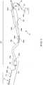
- Figure 1is a perspective view of an electro-mechanical surg ical system 10 according to one embodiment of the present disclosure.
- the electro-mechanical surgical system 10includes a remote power console 12 having a flexible shaft 20 extending therefrom.
- the flexible shaft 20includes at least a first rotatable drive shaft 30 and a second rotatable drive shaft 32. Additional details of the remote power console 12 are described and shown in connection with, e.g., Figure 2 . Additional details of the flexible shaft 20 are described and shown in connection with, e.g., Figures 3 to 6 .
- the surgical attachment 100is configured to perform a surgical operation.
- the surgical attachmentsare described hereinbelow as being circular clamping, cutting and stapling devices that are configured to perform, e.g., an anastomosis procedure.
- the surgical attachmentsmay be any suitable type of surgical device.
- the surgical attachments described hereinbeloware described as being employed within an oral passage of a patient.
- the surgical attachmentsmay be employed within any type of orifice or passage of a patient.
- the surgical attachments described hereinbelowhave a relatively small cross-sectional area, thereby facilitating its passage into, e.g., the oral passages, of a patient.
- the surgical attachment 100may include a handle portion 102. A proximal end 102a of the handle portion 102 is attachable to the coupling 26 at the distal end 24 of the flexible cable 20.
- the surgical attachment 100may also include a flexible shaft 104, through which extends at least a first drive shaft 104a and a second drive shaft 104b. A distal end 102b of the handle portion 102 is attachable to a proximal end 104a of the flexible shaft 104.
- the flexible shaft 104may be formed of a tissue-compatible, sterilizable elastomeric material. Preferably, the flexible shaft 104 may be formed of a material that is autoclavable.
- the flexible shaft 104may be formed of a material having a high or relatively high lubricity.
- the flexible shaft 104may be formed of a material such as TeflonTM (i.e., a fluoropolymer, e.g., polytetrafluoroethylene -- "PTFE"), silicone, a TeflonTM/silicone combination, such as, for example, SIL-KORETM (made by W.L. Gore & Associates), "EPTFE", e.g., expanded teflon, etc.
- TeflonTMi.e., a fluoropolymer, e.g., polytetrafluoroethylene -- "PTFE”
- siliconee.g., silicone
- TeflonTM/silicone combinationsuch as, for example, SIL-KORETM (made by W.L. Gore & Associates)
- EPTFEe.g., expanded teflon
- the surgical attachment 100may also include cutting and stapling component 103.
- a distal end 104b of the flexible shaft 104is attached or attachable to a proximal end 103a of the cutting and stapling component 103.
- One example embodiment of the cutting and stapling component 103is illustrated in Figures 8 to 12(c) .
- the cutting and stapling component 103includes an staple and blade portion 106.
- Extending in an axial direction through a centrally disposed opening of the staple and blade portion 106is a trocar shaft 108, e.g., a cable that may be flexible.
- Disposed at a distal end 108a of the trocar shaft 108is a trocar 110.
- the trocar 110is configured to engage an anvil assembly 112.
- the surgical attachment 100is configured such that the anvil assembly 112 may be selectively moved, e.g., extended and retracted, relative to the staple and blade portion 106, as set forth more fully below.
- the remote power console 12may include a housing 14 having a front panel 15. Mounted on front panel 15 are a display device 16 and indicators 18a, 18b, which are more fully described hereinbelow.
- the flexible shaft 20may extend from the housing 14 and may be detachably secured thereto via a first coupling 22.
- the distal end 24 of the flexible shaft 20may include a second coupling, for instance coupling 26, adapted to detachably secure the surgical attachment 100 to the distal end 24 of the flexible shaft 20.
- the flexible shaft 20includes a tubular sheath 28, which may include a coating or other sealing arrangement to provide a fluid-tight seal between the interior channel 40 thereof and the environment.
- the sheath 28may be formed of a tissue-compatible, sterilizable elastomeric material such as the materials enumerated above in connection with flexible shaft 104.
- the sheath 28may also be formed of a material that is autoclavable.
- FIG. 4is a cross-sectional view of the flexible shaft 20 taken along the line 4-4 shown in Figure 3 and further illustrates the several cables 30, 32, 34, 35, 36, 37, 38.
- Each distal end of the steering cables 34, 35, 36, 37is affixed to the distal end 24 of the flexible shaft 20.
- Each of the several cables 30, 32, 34, 35, 36, 37, 38may be contained within a respective sheath.
- the first rotatable drive shaft 30 and the second rotatable drive shaft 32may be configured, for example, as highly flexible drive shafts, such as, for example, braided or helical drive cables. It should be understood that such highly flexible drive cables have limited torque transmission characteristics and capabilities. It should also be understood that the surgical attachment 100 illustrated in Figure 1 and described hereinbelow, may require a higher torque input than the torque transmittable by the first and second rotatable drive shafts 30, 32.
- the first and second rotatable drive shafts 30, 32may thus be configured to transmit low torque but high speed, the high speed/low torque being converted to low speed/high torque by gearing arrangements disposed, for example, at the distal end 24 and/or a proximal end 20a of the drive flexible shaft 20, in the surgical attachment 100 and/or in the remote power console 12.
- gearing arrangement(s)may be provided at any suitable location along the power train between the motors disposed in the housing 14 and the surgical attachment 100 that is detachably attachable to the flexible shaft 20.
- Such gearing arrangement(s)may include, for example, a spur gear arrangement, a planetary gear arrangement, a harmonic gear arrangement, cycloidal drive arrangement, an epicyclic gear arrangement, etc.
- the first coupling 22includes a first connector 44, a second connector 48, a third connector 52 and a fourth connector 56, each rotatably secured to the first coupling 22.
- Each of the connectors 44, 48, 52, 56includes a respective recess 46, 50, 54, 58.
- each recess 46, 50, 54, 58may be hexagonally shaped.
- the recesses 46, 50, 54, 58may have any shape and configuration to non-rotatabty couple and rigidly attach the connectors 44, 48, 52, 56 to respective drive shafts of the motor arrangement contained within the housing 12, as more fully described below.
- complementary projectionsmay be provided on respective drive shafts of the motor arrangement to thereby drive the drive elements of the flexible shaft 20 as described below.
- the recessesmay be provided on the drive shafts and complementary projections may be provided on the connectors 44, 48, 52, 56. Any other coupling arrangement configured to non-rotatably and releasably couple the connectors 44, 48, 52, 56 and the drive shafts of the motor arrangement may be provided.
- the data transfer cable 38is electrically and logically connected with a data connector 60.
- the data connector 60includes, for example, electrical contacts 62, corresponding to and equal in number to the number of individual wires contained in the data cable 38.
- the first coupling 22includes a key structure 42 to properly orient the first coupling 22 to a mating and complementary coupling arrangement disposed on the remote power console 12.
- Such key structure 42may be provided on either one, or both, of the first coupling 22 and the mating and complementary coupling arrangement disposed on the remote power console 12.
- the first coupling 22may include a quick-connect type connector, which may use, for example, a simple pushing motion to engage the first coupling 22 to the housing 12. Seals may be provided in conjunction with any of the several connectors 44, 48, 52, 56, 60 to provide a fluid-tight seal between the interior of the first coupling 22 and the environment.
- the second coupling 26includes a first connector 66 and a second connector 68, each being rotatably secured to the second coupling 26 and each being non-rotatably secured to a distal end of a respective one of the first and second rotatable drive shafts 30, 32.
- a quick-connect type fitting 64is provided on the second coupling 26 for detachably securing the surgical attachment 100 thereto.
- the quick-connect type fitting 64may be, for example, a rotary quick-connect type fitting, a bayonet type fitting, etc.
- a key structure 74is provided on the second coupling 26 for properly aligning the surgical instrument or attachment to the second coupling 26.
- the key structure 74 or other arrangement for properly aligning the surgical attachment 100 to the flexible shaft 20may be provided on either one, or both, of the second coupling 26 and the surgical attachment 100.
- the quick-connect type fittingmay be provided on the surgical attachment 100.
- a data connector 70, having electrical contacts 72,is also provided in the second coupling 26.
- the data connector 70 of the second coupling 26includes contacts 72 electrically and logically connected to the respective wires of the data transfer cable 38 and the contacts 62 of the data connector 60. Seals may be provided in conjunction with the connectors 66, 68, 70 to provide a fluid-tight seal between the interior of second coupling 26 and the environment.
- electro-mechanical driver elementsDisposed within housing 14 of the remote power console 12 are electro-mechanical driver elements configured to drive the drive shafts 30, 32 and the steering cables 34, 35, 36, 37 to thereby operate the electro-mechanical surgical system 10 and the surgical attachment 100 attached to the second coupling 26.
- five electric motors 76, 80, 84, 90, 96each operating via a power source, may be disposed in the remote power console 12. It should be appreciated, however, that any appropriate number of motors may be provided, and the motors may operate via battery power, line current, a DC power supply, an electronically controlled DC power supply, etc. It should also be appreciated that the motors may be connected to a DC power supply, which is in turn connected to line current and which supplies the operating current to the motors.
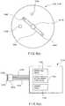
- Figure 6(a)illustrates schematically one possible arrangement of motors.
- An output shaft 78 of a first motor 76engages with the first connector 44 of the first coupling 22 when the first coupling 22, and, therefore, flexible shaft 20, is engaged with the housing 14 to thereby drive the first drive shaft 30 and first connector 66 of second coupling 26.
- an output shaft 82 of a second motor 80engages the second connector 48 of first coupling 22 when first coupling 22, and, therefore, flexible shaft 20 is engaged with the housing 14 to thereby drive the second drive shaft 32 and second connector 68 of second coupling 26.
- An output shaft 86 of a third motor 84engages the third connector 52 of the first coupling 22 when the first coupling 22, and, therefore, flexible shaft 20, is engaged with the housing 14 to thereby drive the first and second steering cables 34, 35 via a first pulley arrangement 88.
- An output shaft 92 of a fourth motor 90engages the fourth connector 56 of the first coupling 22 when the first coupling 22, and, therefore, flexible shaft 20, is engaged with the housing 14 to thereby drive the third and fourth steering cables 36, 37 via a second pulley arrangement 94.
- the third and fourth motors 84, 90may be secured on a carriage 100, which is selectively movable via an output shaft 98 of a fifth motor 96 between a first position and a second position to selectively engage and disengage the third and fourth motors 84, 90 with the respective pulley arrangement 88, 94 to thereby permit the flexible shaft 20 to become taut and steerable or limp as necessary. It should be appreciated that other mechanical, electrical or electro-mechanical mechanisms may be used to selectively engage and disengage the steering mechanism.
- the motorsmay be arranged and configured as described, for example, in non-published U.S. Patent Application Serial No. 09/510,923 , entitled "A Carriage Assembly for Controlling a Steering Wire Mechanism Within a Flexible Shaft".
- any one or more of the motors 76, 80, 84, 90, 96may be high-speed/low-torque motors or low-speed/high-torque motors.
- the first rotatable drive shaft 30 and the second rotatable drive shaft 32may be configured to transmit high speed and low torque.
- the first motor 76 and the second motor 80may be configured as high-speed/low-torque motors.
- first motor 76 and the second motor 80may be configured as low-speed/high-torque motors with a torque-reducing/speed-increasing gear arrangement disposed between the first motor 76 and the second motor 80 and a respective one of the first rotatable drive shaft 30 and the second rotatable drive shaft 32.
- torque-reducing/speed-increasing gear arrangementmay include, for example, a spur gear arrangement, a planetary gear arrangement, a harmonic gear arrangement, cycloidal drive arrangement, an epicyclic gear arrangement, etc. It should be appreciated that any such gear arrangement may be disposed within the remote power console 12 or in the proximal end of the flexible shaft 20, such as, for example, in the first coupling 22. It should be appreciated that the gear arrangement(s) are provided at the distal and/or proximal ends of the first rotatable drive shaft 30 and/or the second rotatable drive shaft 32 to prevent windup and breakage thereof.
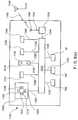
- a controller 1122is provided in the housing 14 of the remote power console 12 and is configured to control all functions and operations of the electro-mechanical surgical system 10 and the surgical attachment 100 attached to the flexible shaft 20.
- a memory unit 1130is provided and may include memory devices, such as, a ROM component 1132 and/or a RAM component 1134.
- the ROM component 1132is in electrical and logical communication with the controller 1122 via line 1136
- the RAM component 1134is in electrical and logical communication with the controller 1122 via line 1138.
- the RAM component 1134may include any type of random-access memory, such as, for example, a magnetic memory device, an optical memory device, a magneto-optical memory device, an electronic memory device, etc.
- the ROM component 1132may include any type of read-only memory, such as, for example, a removable memory device, such as a PC-Card or PCMCIA-type device. It should be appreciated that the ROM component 1132 and the RAM component 1134 may be embodied as a single unit or may be separate units and that the ROM component 1132 and/or the RAM component 1134 may be provided in the form of a PC-Card or PCMCIA-type device.
- the controller 1122is further connected to the front panel 15 of the housing 14 and, more particularly, to the display device 16 via line 1154 and the indicators 18a, 18b via respective lines 1156, 1158.
- the lines 1116, 1118, 1124, 1126, 1128electrically and logically connect the controller 1122 to the first, second, third, fourth and fifth motors 76, 80, 84, 90, 96, respectively.
- a wired remote control unit (“RCU") 1150is electrically and logically connected to the controller 1122 via line 1152.
- a wireless RCU 1148is also provided and communicates via a wireless link 1160 with a receiving/sending unit 1146 connected via line 1144 to a transceiver 1140.
- the transceiver 1140is electrically and logically connected to the controller 1122 via line 1142.
- the wireless link 1160may be, for example, an optical link, such as an infrared link, a radio link or any other form of wireless communication link.
- a switch device 1186which may be, for example, an array of DIP switches, may be connected to the controller 1122 via line 1188.
- the switch device 1186may be used, for example, to select one of a plurality of languages used in displaying messages and prompts on the display device 16.
- the messages and promptsmay relate to, for example, the operation and/or the status of the electro-mechanical surgical system 10 and/or to the surgical attachment attached thereto.
- a first encoder 1106is provided within the second coupling 26 and is configured to output a signal in response to and in accordance with the rotation of the first drive shaft 30.
- a second encoder 1108is also provided within the second coupling 26 and is configured to output a signal in response to and in accordance with the rotation of the second drive shaft 32.
- the signal output by each of the encoders 1106, 1108may represent the rotational position of the respective drive shaft 30, 32 as well as the rotational direction thereof.
- Such encoders 1106, 1108may be, for example, Hall-effect devices, optical devices, etc.
- the encoders 1106, 1108are described as being disposed within the second coupling 26, it should be appreciated that the encoders 1106, 1108 may be provided at any location between the motor system and the surgical instrument or attachment. It should be appreciated that providing the encoders 1106, 1108 within the second coupling 26 or at the distal end of the flexible shaft 20 provides for an accurate determination of the drive shaft rotation. If the encoders 1106, 1108 are disposed at the proximal end of the flexible shaft 20, windup of the first and second rotatable drive shafts 30, 32 may result in measurement error.
- Figure 6(c)is a schematic view of an encoder 1106,1108, which includes a Hall-effect device.
- a magnet 240having a north pole 242 and a south pole 244.
- the encoder 1106, 1108further includes a first sensor 246 and second sensor 248, which are disposed approximately 90° apart relative to the longitudinal, or rotational, axis of drive shaft 30, 32.
- the output of the sensors 246, 248is persistent and changes its state as a function of a change of polarity of the magnetic field in the detection range of the sensor.
- the angular position of the drive shaft 30, 32may be determined within one-quarter revolution and the direction of rotation of the drive shaft 30, 32 may be determined.
- the output of each encoder 1106,1108is transmitted via a respective line 1110, 1112 of data transfer cable 38 to controller 1122.
- the controller 1122by tracking the angular position and rotational direction of the drive shafts 30, 32 based on the output signal from the encoders 1106, 1108, can thereby determine the position and/or state of the components of the surgical attachment 100 connected to the electro-mechanical surgical system 10. That is, by counting the revolutions of the drive shaft 30, 32, the controller 1122 can determine the position and/or state of the components of the surgical attachment 100 connected to the electro-mechanical surgical system 10.
- the surgical attachment 100may further include, according to one embodiment and as shown in Figure 6(d) , a data connector 1272 adapted by size and configuration to electrically and logically connect to the connector 70 of the second coupling 26.
- the data connector 1272includes contacts (not shown) equal in number to the number of leads 72 of the connector 70.
- Contained within the surgical attachment 100is a memory unit 1174 electrically and logically connected with the data connector 1272.
- the memory unit 1174may be in the form of, for example, an EEPROM, EPROM, etc. and may be contained, for example, within the staple and blade portion 106 of the surgical attachment 100.
- Figure 6(d)schematically illustrates the memory unit 1174.
- the data connector 1272includes contacts 1276, each electrically and logically connected to the memory unit 1174 via a respective line 1278.
- the memory unit 1174is configured to store, for example, a serial number data 1180, an attachment type identifier (ID) data 1182 and a usage data 1184.
- the memory unit 1174may additionally store other data.
- Both the serial number data 1180 and the ID data 1182may be configured as read-only data.
- the serial number data 1180is data uniquely identifying the particular surgical attachment
- the ID data 1182is data identifying the type of the attachment (when, for instance, other types of attachments may be employed by the device).
- the usage data 1184represents usage of the particular attachment, such as, for example, the number of times the anvil assembly 112 of the surgical attachment 100 has been retracted or extended, or the number of times that the staple pusher 220 of the surgical attachment 100 has been advanced or fired, as set forth more fully below.
- the surgical attachment 100 attachable to the distal end 24 of the flexible shaft 20may be designed and configured to be used a single time or multiple times.
- the surgical attachment 100may also be designed and configured to be used a predetermined number of times.
- the usage data 1184may be used to determine whether the surgical attachment 100 has been used and whether the number of uses has exceeded the maximum number of permitted uses. As more fully described below, an attempt to use the surgical attachment 100 after the maximum number of permitted uses has been reached will generate an ERROR condition.
- the controller 1122is configured to read the ID data 1182 from the memory unit 1174 of the surgical attachment 100 when the surgical attachment 100 is initially connected to the flexible shaft 20.
- the memory unit 1174is electrically and logically connected to the controller 1122 via line 1120 of data transfer cable 38.
- the controller 1122is configured to read or select from the memory unit 1130, an operating program or algorithm corresponding to the type of surgical instrument or attachment connected to the flexible shaft 20.
- the memory unit 1130is configured to store the operating programs or algorithms for each available type of surgical instrument or attachment, the controller 1122 selecting and/or reading the operating program or algorithm from the memory unit 1130 in accordance with the ID data 1182 read from the memory unit 1174 of an attached surgical instrument or attachment.
- the memory unit 1130may include a removable ROM component 1132 and/or RAM component 1134.
- the operating programs or algorithms stored in the memory unit 1130may be updated, added, deleted, improved or otherwise revised as necessary.
- the operating programs or algorithms stored in the memory unit 1130may be customizable based on, for example, specialized needs of the user.
- a data entry devicesuch as, for example, a keyboard, a mouse, a pointing device, a touch screen, etc., may be connected to the memory unit 1130 via, for example, a data connector port, to facilitate the customization of the operating programs or algorithms.
- the operating programs or algorithmsmay be customized and preprogramed into the memory unit 1130 remotely from the electro-mechanical surgical system 10.
- the serial number data 1180 and/or the usage data 1184may also be used to determine which of a plurality of operating programs or algorithms is read or selected from the memory unit 1130.
- the operating program or algorithmmay alternatively be stored in the memory unit 1174 of the surgical attachment 100 and transferred to the controller 1122 via the data transfer cable 38.
- the controller 1122causes the operating program or algorithm to be executed in accordance with operations performed by the user via the wired RCU 1150 and/or the wireless RCU 1148.
- the controller 1122is electrically and logically connected with the first, second, third, fourth and fifth motors 76, 80, 84, 90, 96 via respective lines 1116, 1118, 1124, 1126, 1128 and controls such motors 76, 80, 84, 90, 96 in accordance with the read, selected or transmitted operating program or algorithm via the respective lines 1116, 1118, 1124, 1126,1128.
- the wireless RCU 1148includes a steering controller 1300 having a plurality of switches 1302, 1304, 1306, 1308 arranged under a four-way rocker 1310.
- the operation of switches 1302, 1304, via the rocker 1310controls the operation of the first and second steering cables 34, 35 via the third motor 84.
- the operation of the switches 1306, 1308, via the rocker 1310controls the operation of the third and fourth steering cables 36, 37 via the fourth motor 92.
- rocker 1310 and the switches 1302, 1304, 1306, 1308are arranged so that the operation of the switches 1302, 1304 steers the flexible shaft 20 in the north-south direction and that the operation of the switches 1306, 1308 steers the flexible shaft 20 in the east-west direction.
- Reference herein to north, south, east and westis made to a relative coordinate system.
- a digital joystick, analog joystick, etc.may be provided in place of the rocker 1310 and the switches 1302, 1304, 1306, 1308. Potentiometers or any other type of actuator may also be used in place of the switches 1302,1304,1306,1308.
- the wireless RCU 1148further includes a steering engage/disengage switch 1312, the operation of which controls the operation of the fifth motor 96 to selectively engage and disengage the steering mechanism.
- the wireless RCU 1148also includes a two-way rocker 1314 having first and second switches 1316, 1318 operable thereby. The operation of these switches 1316, 1318 controls certain functions of the electro-mechanical surgical system 10 and any surgical attachment, such as surgical attachment 100, attached to the flexible shaft 20 in accordance with the operating program or algorithm corresponding to the attached surgical attachment, if any.
- operation of the two-way rocker 1314may control the extension and retraction of the anvil assembly 112 of the surgical attachment 100.
- the wireless RCU 1148is provided with yet another switch 1320, the operation of which may further control the operation of the electro-mechanical surgical system 10 and any surgical attachment attached to the flexible shaft 20 in accordance with the operating program or algorithm corresponding to the attached surgical attachment, if any.
- operation of the switch 1320may initiate the advancement, or firing sequence, of the staple pusher 220.
- the wireless RCU 1148includes a controller 1322, which is electrically and logically connected with the switches 1302, 1304, 1306, 1308 via line 1324, with the switches 1316, 1318 via line 1326, with the switch 1312 via line 1328 and with the switch 1320 via line 1330.
- the wireless RCU 1148may include indicators 18a', 18b', corresponding to the indicators 18a, 18b of the front panel 15, and a display device 16', corresponding to the display device 16 of the front panel 15. If provided, the indicators 18a', 18b' are electrically and logically connected to the controller 1322 via respective lines 1332, 1334, and the display device 16' is electrically and logically connected to the controller 1322 via line 1336.
- the controller 1322is electrically and logically connected to a transceiver 1338 via line 1340, and the transceiver 1338 is electrically and logically connected to a receiver/transmitter 1342 via line 1344.
- a power supplynot shown, for example, a battery, may be provided in the wireless RCU 1148 to power the same.
- the wireless RCU 1148may be used to control the operation of the electro-mechanical surgical system 10 and any surgical attachment 100 attached to the flexible shaft 20 via wireless link 1160.
- the wireless RCU 1148may include a switch 1346 connected to the controller 1322 via line 1348. Operation of the switch 1346 transmits a data signal to the transmitter/receiver 1146 via the wireless link 1160.
- the data signalincludes identification data uniquely identifying the wireless RCU 1148. This identification data is used by the controller 1122 to prevent unauthorized operation of the electro-mechanical surgical system10 and to prevent interference with the operation of the electro-mechanical surgical system 10 by another wireless RCU. Each subsequent communication between the wireless RCU 1148 and the electro-mechanical surgical system 10 may include the identification data.
- the controller 1122can discriminate between wireless RCUs and thereby allow only a single, identifiable wireless RCU 1148 to control the operation of the electro-mechanical surgical system 10 and any surgical attachment attached to the flexible shaft 20.
- the controller 1122may selectively enable or disable the functions of the electro-mechanical surgical system 10 as defined by the operating program or algorithm corresponding to the attached surgical attachment 100. For example, where the surgical attachment is the surgical attachment 100 illustrated in Figure 1 , the firing function controlled by the operation of the switch 1320 is disabled unless the space or gap between the anvil assembly 112 and the staple and blade portion 106 is determined to be within an acceptable range. The space or gap between the anvil assembly 112 and the staple and blade portion 106 is determined based on the output signal from the encoders 1106, 1108, as more fully described hereinabove. It should be appreciated that the switch 1320 itself remains operable but that the controller 1122 does not effect the corresponding function unless the space or gap is determined to be within the acceptable range.
- the wired RCU 1150includes substantially the same control elements as the wireless RCU 1148 and further description of such elements is omitted. Like elements are noted in Figure 6(f) with an accompanying prime. It should be appreciated that the functions of the electro-mechanical surgical system 10 and any surgical attachment attached to the flexible shaft 20 may be controlled by the wired RCU 1150 and/or by the wireless RCU 1148. In the event of a battery failure, for example, in the wireless RCU 1148, the wired RCU 1150 may be used to control the functions of the electro-mechanical surgical system 10 and any surgical attachment 100 attached to the flexible shaft 20.
- the front panel 15 of housing 14includes display device 16 and indicators 18a, 18b.
- the display device 16may include an alphanumeric display device, such as an LCD display device.
- the display device 16may also include an audio output device, such as a speaker, a buzzer, etc.
- the display device 16is operated and controlled by controller 1122 in accordance with the operating program or algorithm corresponding to a surgical attachment 100 attached to the flexible shaft 20. If no surgical attachment is so attached, a default operating program or algorithm may be read or selected by, or transmitted to, controller 1122 to thereby control the operation of the display device 16 as well as the other aspects and functions of the electro-mechanical surgical system 10.
- display device 16may display, for example, data indicative of the gap between the anvil assembly 112 and the staple and blade portion 106 as determined in accordance with the output signal of encoders 1106, 1108, as more fully described hereinabove.
- the indicators 18a, 18bare operated and controlled by the controller 1122 in accordance with the operating program or algorithm corresponding to the surgical attachment 100 attached to the flexible shaft 20.
- the indicator 18a and/or the indicator 18bmay include an audio output device, such as a speaker, a buzzer, etc., and/or a visual indicator device, such as an LED, a lamp, a light, etc. If the surgical attachment 100 illustrated in Figure 1 is attached to the flexible shaft 20, the indicator 18a may indicate, for example, that the electro-mechanical surgical system 10 is in a power ON state, and the indicator 18b may, for example, indicate whether the gap between the anvil assembly 112 and the staple and blade portion 106 is determined to be within the acceptable range as more fully described hereinabove. It should be appreciated that although only two indicators 18a, 18b are described, any number of additional indicators may be provided as necessary. Additionally, it should be appreciated that although a single display device 16 is described, any number of additional display devices may be provided as necessary.
- the display device 16' and the indicators 18a', 18b' of the wireless RCU 1150 and the display device 16" and the indicators 18a", 18b" of the wired RCU 1148are similarly operated and controlled by the respective controller 1322, 1322' in accordance with the operating program or algorithm corresponding to the surgical attachment 100 attached to the flexible shaft 20.
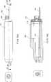
- Figures 7(a) to 7(f)are various views of the handle portion 102 of the surgical attachment 100, according to one embodiment of the present disclosure.
- Figure 7(a)is a front perspective view
- Figure 7(b)is a rear perspective view, of the handle portion 102 including a housing 301.
- a coupling block 305At a distal end 301b of the housing 301 is disposed a coupling block 305.
- Extending from the gear housing 302is a quick connect coupling 304 and an extension rod 308.
- the quick-connect coupling 304is mounted onto the gear housing 302 and may be biased, e.g., via a set of springs.
- the gear housing 302includes a first drive socket 304a and a second drive socket 304b.
- Figure 7(c)is an exploded front perspective view of the handle portion 102.
- the first drive socket 304aincludes a first input element 306a, one end 3061 of which extends through an opening 3021 of the gear housing 302 and the other end 3062 of which includes spur gear teeth 3063.
- the second drive socket 304bincludes a second input element 306b, one end 3064 of which extends through a second opening 3022 of the gear housing 302 and the other end 3065 of which includes spur gear teeth 3066.
- the extension rod 308extends through an extension rod opening 3025 in the gear housing 302.
- the distal end 308b of the extension rod 308has a flange 3081 that is larger than the extension rod opening 3025 such that the flange 3081 of the extension rod 308 is retained within the gear housing 302.
- the flange 3081 of the extension rod 308abuts one side of the spur gear 310, the spur gear 310 being seated within an internal recess 3023 of the gear housing 302.
- the spur gear 310has arranged along its outer circumference spur gear teeth 3101 that correspond to the spur gear teeth 3063 of the first input element 306a.
- the rod 312is connected to a coupling element 314 that is positioned within a first opening 3052 of the coupling block 305.
- the rod coupling 314may provide a connection to the first drive shaft 104a of the flexible shaft 104.
- a spur gear 318is also seated within an internal recess 3024 of the gear housing 302 .
- the spur gear 318has arranged along its outer circumference spur gear teeth 3181 that correspond to the spur gear teeth 3066 of the second input element 306b.
- the spur gear 318has a bore 3182 extending therethrough.
- Non-rotatably engaged within the bore 3182 of the spur gear 318is a first end 3161 of a shaft drive element 316.
- a second end 3162 of the shaft drive element 316is configured to non-rotatably engage the second drive shaft 104b of the flexible shaft 104, which extends through a second opening 3053 in the distal face 3051 of the coupling block 305.
- Figure 7(d)is a top view of the handle portion 102 illustrated in Figure 7(a) .
- Figure 7(e)is a side cross-sectional view of the handle portion 102 illustrated in Figure 7(d) taken along the lines A-A.
- Figure 7(f)is a side cross-sectional view of the handle portion 102 illustrated in Figure 7(d) taken along the lines B-B.
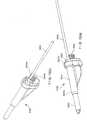
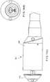
- FIG 8is a perspective view of the cutting and stapling component 103 of the surgical attachment 100, according to one embodiment of the present disclosure.
- the cutting and stapling component 103includes a staple and blade portion 106.
- Extending in an axial direction through a centrally disposed opening of the staple and blade portion 106is a trocar shaft 108.
- the trocar shaft 108may be flexible.
- the trocar shaft 108is a cable.
- Disposed at a distal end 108a of the trocar shaft 108is a trocar 110.
- the trocar 110has a sharp or pointed end that is configured to be pushed through a section of tissue.
- the trocar 110is configured to engage an anvil assembly 112, preferably by being insertable within a slot of the anvil assembly 112 for detachably fixing the trocar 110, and thus the trocar shaft 108 attached thereto, to the anvil assembly 112 as set forth more fully below.
- the surgical attachment 100is configured such that the trocar shaft 108, and the anvil assembly 112 attached thereto, may be selectively moved, e.g., extended and retracted, relative to the staple and blade portion 106, as set forth more fully below.
- the trocar shaft 108having the trocar 110 disposed at its end, is extendable and retractable by movement in first and second, e.g., distal and proximal, directions, respectively, to a desired distance relative to the staple and blade portion 106.
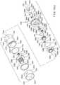
- Figure 9is a perspective view that illustrates a cutting and stapling component 103, according to one embodiment of the present disclosure.
- Figure 9shows the cutting and stapling component 103 in an assembled, partially closed position.
- Figure 9illustrates the anvil assembly 112 in a partially retracted position relative to the staple and blade portion 106.
- FIG 10(a)is a perspective view that illustrates the components of the anvil assembly 112, according to one embodiment of the present disclosure.
- Figure 10(a)shows the anvil assembly 112 in an exploded condition.
- the anvil assembly 112includes an anvil end cap 202.
- the anvil end cap 202has a centrally-disposed opening 2021 arranged in the axial direction.
- the anvil end cap 202also includes a radially-disposed slot 2022 on a distal side 2025 of the end cap 202, and a clamping face 2023 on a proximal side 2026 of the anvil end cap 202.
- the clamping face 2023has a recessed portion that forms a blade repository 2024.
- the clamping face 2023also defines sta pie guides 2026.
- the anvil assembly 112also includes a pin 204 corresponding cross-sectionally to the slot 2022 of the anvil end cap 202.
- the anvil assembly 112also includes a hollow anvil sleeve 208.
- a distal end 2081 of the anvil sleeve 208corresponds cross-sectionally to the opening 2021 of the anvil end cap 202.
- the distal end 2081 of the anvil sleeve 208defines openings 2082 that correspond cross-sectionally to the anvil pin 204.
- a recess 2086that extends circumferentially around the anvil sleeve 208 and that has a radius that is smaller than the radius of the other portions of the anvil sleeve 208, including the radius of several radially-extending teeth 2087 located at the proximal-most end of the anvil sleeve 208.
- the proximal end 2084 of the anvil sleeve 208also defines a plurality, e.g., four, axial slots 2088 that extend through the recess 2086 and the teeth 2087, thereby enabling the proximal end 2084 of the anvil sleeve 208 to be radially compressed.
- the anvil sleeve 208also includes one or more longitudinally-extending keys 2085 on its outer surface.
- the anvil assembly 112also includes an anvil extension rod 206.
- the anvil extension rod 206has a distal end 2061 that may be flat and that defines an opening 2062.
- the anvil extension rod 206also has a central region 2063 that is round and that corresponds cross-sectionally to an inner diameter of the recess 2086 of the anvil sleeve 208.
- the distal end 2061 of the anvil extension rod 206is cross-sectionally larger than the inner diameter of the recess 2086 of the anvil sleeve 208.
- the anvil extension rod 206also has a proximal end 2063 that defines a trocar receiving slot 2065.
- Figure 10(b)is a perspective view that illustrates some of the components of the staple and blade portion 106, according to one embodiment of the present i disclosure.
- Figure 10(b)shows the components in an exploded condition.
- the staple and blade portion 106includes a hollow anvil sleeve guide 210.
- the inner surface of the anvil sleeve guide 210includes one or more keyways 2101.
- the outer surface of the anvil sleeve guide 210includes a lip 2102, such that a proximal end 2103 of the anvil sleeve guide 210 has a larger radius than a distal end 2104 of the anvil sleeve guide 210.
- the staple and blade portion 106also includes an outer housing sleeve 212.
- the outer housing sleeve 212has one or more openings 2121 at its distal end 2122, and a radially inwardly-extending lip 2123 at the distal end 2124 of the outer housing sleeve 212.
- the staple and blade portion 106also includes a staple cartridge 214.
- the staple cartridge 214defines a plurality of axially-disposed staple receiving slots 2141 in which staples 2142 are stored. In the embodiment shown in Figure 10(b) , the staple receiving slots 2141 are disposed circumferentially around the staple cartridge 214 in two radially-spaced apart rows, wherein the staple receiving slots 2141 in the first row overlap the staple receiving slots 2141 in the second row.
- the staple cartridge 214also includes a radially inwardly-extending lip 2145 located near the distal end 2147 of the staple cartridge 214 and a radially outwardly-extending lip 2143 located near the proximal end 2144 of the staple cartridge 214. Furthermore, the distal end 2147 of the staple cartridge 214 defines a clamping face 2146.
- the staple and blade portion 106also includes a frangible blade protection ring 216 that defines within its interior a slot 2161.
- the staple and blade portion 106includes a blade 218.
- the blade 218has a cutting edge 2183 that extends circumferentially along its distal end 2184.
- the blade 218defines a radially, inwardly-extending tab or lip 2181 at its proximal end 2182.
- the staple and blade portion 106also includes a staple pusher 220.
- the staple pusher 220has a plurality of axially-disposed pushing teeth 2201, each of which corresponds to and aligns with the staple receiving slots 2141 of the stapler cartridge 214.
- the staple pusher 220also includes a key 2202 on its outer surface.
- the staple and blade portion 106also includes a staple pusher carriage element 222 that has a neck portion 2221 and a flange portion 2222, the neck portion 2221 extending axially in a distal direction relative to the flange portion 2222.
- An interior surface of the neck portion 2221includes threads 2223, while an exterior surface of the neck portion 2221 defines a circumferentially-disposed recess 2224.
- the radially outermost edge of the flange 2222includes a key 2225.
- FIG 10(c)is a perspective view that illustrates the remaining components of the staple and blade portion 106 in an exploded condition, according to one embodiment of the present disclosure.
- the staple and blade portion 106also includes a split ring 224.
- the split ring 224includes a pair of semicircular ring portions 2241 and 2242 that when arranged in the shape of a ring define therebetween a pair of keyways 2243 and 2244.
- the staple and blade portion 106also includes a washer 226.
- the staple and blade portion 106also includes a thrust element 228 that has a neck portion 2281 and a flange portion 2282, the neck portion 2281 extending axially in a distal direction relative to the flange portion 2282.
- a bore 2283is defined within the interior of the neck portion 2281, while an exterior surface of the neck portion 2281 defines threads 2284 that correspond to the threads 2223 located on the interior surface of the neck portion 2221 of the staple pusher carriage element'222.
- the flange 2282 of the thrust element 228includes one or more bores 2285 within its distally-facing surface, and a proximally-extending pin 2286 having, e.g., a round cross section.
- the staple and blade portion 106also includes a first spur gear 230.
- the first spur gear 230defines an internal bore 2301 that corresponds cross-sectionally to the pin 2286 of the thrust element 228.
- the first spur gear 230also includes circumferentially-disposed spur gear teeth 2302.
- the staple and blade portion 106also includes a washer 232, and an inner housing sleeve 234.
- the inner housing sleeve 234includes an internal bore 2341 that has a first interior radius at a distal end 2342 of the inner housing sleeve 234.
- the internal bore 2341extends proximally towards a radially inwardly-extending lip 2345 at which point the interior radius of the internal bore 2342 is reduced.
- the internal bore 2342extends still further proximally to a second radially inwardly-extending lip 2346 at which point the interior radius of the internal bore 2342 is again reduced.
- Proximal to the second lip 2346are gear teeth 2347 that extend circumferentially along the interior surface of the inner housing sleeve 234.
- a proximal end 2343e.g., proximal relative to the gear teeth 2347, has a smooth interior surface, and has one or more radial openings 2344 defined therein.
- the staple and blade portion 106also includes a sun gear element 236 that has a neck portion 2361 and a flange portion 2362, the neck portion 2361 extending axially in a distal direction relative to the flange portion 2362.
- a bore 2363is defined within the interior of the neck portion 2361, while an exterior surface of the neck portion 2361 has circumferentially-disposed gear teeth 2364 that correspond to the gear teeth 2302 of the first spur gear 230.
- the flange portion 2362includes a proximally-extending pin 2366 having, e.g., a round cross section.
- the staple and blade portion 106also includes a washer 238.
- the staple and blade portion 106also includes a first planetary gear 240 having an internal bore 2401. An exterior surface of the first planetary gear 240 has circumferentially-disposed gear teeth 2402.
- the staple and blade portion 106also includes a sun gear 242 having an internal bore 2421. An exterior surface of the sun gear 242 has circumferentially-disposed gear teeth 2422 that correspond to the gear teeth 2402 of the first planetary gear 240.
- the staple and blade portion 106also includes a washer 244 having a tab 2441.
- the staple and blade portion 106also includes a second planetary gear 246 having an internal bore 2461. An exterior surface of the second planetary gear 246 has circumferentially-disposed gear teeth 2462 that correspond to circumferentially-disposed gear teeth 2422 of the sun gear 242.
- the staple and blade portion 106also includes an input element 248.
- a distal end 2481 of the input element 248has an internal bore 2483, which may have, e.g., a square cross-section.
- On an outer surface of the distal end 2481 of the input element 248are circumferentially-disposed gear teeth 2482 that correspond to the circumferentially-disposed gear teeth 2462 on the exterior surface of the second planetary gear 246.
- a proximal end 2484 of the input element 248has a round outer circumference and an internal bore 2485.
- the staple and blade portion 106also includes a housing rear endcap 250 having a central bore 2501, a second bore 2502 radially offset relative to the central bore 2501, and a recess 2503 from which a pin 2504 extends in a distal direction.
- the housing rear endcap 250also includes an outer radial lip 2505. Located distally relative to the outer radial lip 2505 is at least one opening 2506 defined within a round outer circumferential surface 2507.
- the housing rear endcap 250also includes at its proximal end one or more keyways 2509 in communication with the central bore 2501.
- the staple and blade portion 106also includes a central rear endcap sleeve 252 having a bore 2521 disposed therethrough. At a distal end 2522 of the central rear endcap sleeve 252, the bore 2521 defines a radially inwardly-extending rim 2523. At a proximal end 2524 of the central rear endcap sleeve 252 are oppositely-disposed keyways 2525.
- the staple and blade portion 106also includes a retainer sleeve 254 having a bore 2541 disposed therethrough. At a proximal end 2542 of the retainer sleeve 254 are oppositely-disposed keys 2543 that correspond to the oppositely-disposed keyways 2525 located at the proximal end 2524 of the central rear en dcap sleeve 252 and the keyways 2509 of the rear housing endcap 250.
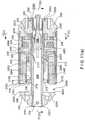
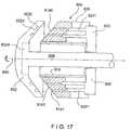
- Figure 11(a)is a top, cross-sectional view and Figure 11(b) is a side, cross-sectional view that illustrate the cutting and stapling component 103, according to one embodiment of the present disclosure.
- Figures 11(a) and 11(b)show the cutting and stapling component 103 in an assembled and partially retracted position, as set forth more fully below.
- the distal end 2081 of the anvil sleeve 208is inserted into the corresponding, centrally-disposed opening 2021 in the anvil end cap 202.
- the anvil pin 204is inserted through the radially-d isposed slot 2022 of the end cap 202 and through the oppositely-disposed openings 2082 in the distal end 2081 of the anvil sleeve 208 so that the anvil end cap 202 is axially and rotatably fixed relative to the anvil sleeve 208.
- the distal end 2061 of the anvil extension rod 206is axially retained within the recess 2086 at the proximal end 2084 of the anvil sleeve 208.
- the anvil sleeve 208is axially and slidably retained within the interior of the anvil sleeve guide 210.
- the anvil sleeve 208is prevented from rotating relative to the anvil sleeve guide 210 by the engagement of the keys 2085 of the anvil sleeve 208 within the keyways 2101 of the anvil sleeve guide 210.
- the central rear endcap sleeve 252Extending through the central opening 2501 of the housing rear end 250 and into the proximal end 2103 of the anvil sleeve guide 210 is the central rear endcap sleeve 252. In the position shown, the rim 2523 of the central rear endcap sleeve 252 is engaged within the recess 2086 of the anvil sleeve 208, thereby axially fixing the central rear endcap sleeve 252 and the anvil sleeve 208 relative to each other. Inserted into the bore 2521 of the central rear endcap sleeve 252 is the retainer sleeve 254.
- the keys 2543 of the retainer sleeve 254engage the keyways 2525 of the central rear endcap sleeve 252 and the keyways 2509 of the housing rear endcap 250 so as to prevent relative rotation between the retainer sleeve 254, the central rear endcap sleeve 252 and the housing rear endcap 250.
- the input element 248is rotatably maintained within the second opening 2502 of the housing rear end cap 250.
- the teeth 2482 of the input element 248are in meshing engagement with the circumferentially-disposed teeth 2462 of the second planetary gear 246, which is rotatably mounted on the pin 2504 extending distally from the recess 2503 of the housing rear endcap 250.
- the circumferentially-disposed teeth 2462 of the second planetary gear 246are also in meshing engagement with circumferentially-disposed teeth 2422 of the sun gear 242.
- the sun gear 242is rotatably mounted via its internal bore 2421 on the proximal end 2103 of the anvil sleeve guide 210.
- the circumferentially-disposed teeth 2422 of the sun gear 242are also in meshing engagement with the circumferentially-disposed teeth 2402 of the first planetary gear 240.
- the first planetary gear 240is rotatably mounted on the pin 2361 that extends proximally from the flange portion 2362 of the sun gear element 236.
- the circumferentially-disposed teeth 2402 of the first planetary gear 240are also in meshing engagement with the gear teeth 2347 that extend circumferentially around the interior surface of the inner housing sleeve 234.
- the inner housing sleeve 234is rotatably and axially fixed relative to the housing rear endcap 250 and the outer housing sleeve 212 by the insertion of fasteners 256, e.g., pins or screws, through aligned openings 2121, 2344 and 2506 in the outer housing sleeve 212, the inner housing sleeve 234 and the housing rear endcap 250, respectively.
- fasteners 256e.g., pins or screws
- the sun gear element 236is rotatably mounted via its internal bore 2363 on the anvil sleeve guide 210.
- the circumferentially-disposed gear teeth 2364 on the exterior surface of the neck portion 2361 of the sun gear element 236are in meshing engagement with the circumferentially-disposed gear teeth 2302 of the first spur gear 230.
- the first spur gear 230is rotatably mounted on the thrust element 228 by the internal bore 2301 of the first spur gear 230 having inserted therein the proximally-extending pin 2286 of the thrust element 228.
- the circumferentially-disposed gear teeth 2302 of the first spur gear 230are also in meshing engagement with the gear teeth 2347 that extend circumferentially around the interior surface of the inner housing sleeve 234.
- the thrust element 228is rotatably mounted on the anvil sleeve guide 210 by the anvil sleeve guide 210 fitting within the internal bore 2283 of the thrust element 228.
- the washer 232resides between the proximal surface of the flange 2282 of the thrust element 282 and the second lip 2346 of the inner housing sleeve 234, while the washer 226 resides between the distal surface of the flange 2282 of the thrust element 282 and the flange 2222 of the staple cartridge carrier element 222.
- the staple pusher carriage element 222is mounted on the thrust element 228 such that the threads 2223 located on the interior surface of the neck portion 2221 of the staple pusher carriage element 222 are in threaded engagement with the threads 2284 located on the exterior surface of the neck portion 2281 of the thrust element 228.
- the keys 2225 of the staple pusher carriage element 222are engaged within the keyways 2243 formed by the split ring 224, thereby enabling the staple pusher carriage element 222 to be axially slidable relative to the split ring 224.
- the split ringis positioned within the bore 2341 at the distal end 2342 of the inner housing sleeve 234.
- the staple pusher 220Located within the split ring 224, and abutting the flange 2282 of the thrust element 228 is the staple pusher 220.
- the keys 2202 of the staple pusher 220are engaged within the keyways 2243 formed by the split ring 224, thereby enabling the staple pusher 220 to be axially slidable relative to the split ring 224.
- the pushing teeth 2201 of the staple pusher 220extend distally and align with the staple receiving slots 2141 of the staple cartridge 214.
- the staple cartridge 214is positioned distally relative to the staple pusher 220 and is maintained within the interior of the outer housing sleeve 212.
- the staple cartridge 214is axially moveable in a distal direction within the outer housing sleeve 212 from the position shown in Figures 11(a) and 11(b) until the radially, outwardly-extending lip 2143 of the staple cartridge 214 abuts the radially, inwardly-extending lip 2123 of the outer housing sleeve 212 as set forth more fully below.
- the blade 218Located between the staple pusher 220 and the staple pusher carriage element 222 is the blade 218.
- the radially, inwardly-extending tab or lip 2185 located at the distal end 2182 of the bladeis engaged within the recess 2224 located on the outer surface of the neck portion 2221 of the staple pusher carriage element 222.
- the cutting edge 2183 of the blade 218is sheathed within the slot 2161 of the frangible blade protection ring 216.
- the frangible blade protection ring 216axially abuts the radially inwardly-extending lip 2144 of the staple cartridge 214.
- the surgical attachment 100is attached via the quick connect coupling 304 of the handle portion 102to the flexible shaft 20 such that the first rotatable drive shaft 30 of the flexible shaft 20 is coupled, e.g., non-rotatably, to the first input element 306a of the handle portion 102 and such that the second rotatable drive shaft 32 of the flexible shaft 20 is coupled, e.g., non-rotatably, to the second input element 306b of the handle portion 102.
- the trocar shaft 108 of the surgical attachment 100may be in a retracted position, such as illustrated in Figure 9 , so as to facilitate the insertion of the surgical attachment 100 into the body of a patient.
- the staple and blade portion 106may be inserted into an oral passage of the patient.
- the controller 1122may initially be configured to operate in a clamping mode.
- rotation of the first rotatable drive shaft 30 in a first directione.g., clockwise when viewed from the proximal end, causes rotation of the input element 306a in the first direction.
- the spur gear 310is caused to rotate in a second direction, e.g., counter-clockwise when viewed from the proximal end.
- Rotation of the spur gear 310 in the second directioncauses the rod 312, the threads of which are engaged within the threaded internal bore 3102 of the spur gear 310, to move axially within the housing portion 102.
- the coupling element 314 at the end of the rod 312is engaged, e.g., non-rotatably, with the first drive shaft 104a of the flexible shaft 104, which in turn is engaged, e.g., non-rotatably, with the trocar shaft 108 extending through the staple and blade portion 106 of the cutting and stapling component 103.
- the trocar shaft 108having the trocar 110 disposed at its end, may be extended by movement in a first, e.g., distal, direction to a desired distance relative to the staple and blade portion 106.
- the trocar 110is pushed through a section of tissue desired to be stapled and is inserted within the trocar receiving slot 2065 of the anvil extension rod 206 so as to be axially fixed relative to the anvil extension rod 206.
- the trocar shaft 108is then retracted by operation of the first rotatable drive shaft 30 in the opposite direction so as to draw the anvil extension rod 206, and the other components of the anvil assembly 112, into the anvil sleeve guide 210.
- the keys 2085 of the anvil sleeve 208engage with the keyways 2101 within the anvil sleeve guide 210 to thereby align the anvil assembly 112 with the staple and blade portion 106.
- Still further retraction of the trocar shaft 108causes the anvil sleeve 108 to move proximally within the anvil sleeve guide 210 until the rim 2523 of the central rear endcap sleeve 252 seats within the recess 2086 of the anvil sleeve 208.
- the anvil assembly 112When the rim 2523 of the central rear endcap sleeve 252 seats within the recess 2086 of the anvil sleeve 208, the anvil assembly 112 is axially locked in position relative to the staple and blade portion 106. According to one embodiment of the present disclosure, the anvil assembly 112 is axially locked in position relative to the staple and blade portion 106 when the clamping face 2023 of the anvil end cap 202 is at a distance of approximately 5mm from the clamping face 2146 of the staple cartridge 214.
- the controller 1122may cease rotation of the first rotatable drive shaft 30 in the second direction.
- the controller 1122may then change to a firing mode of operation.
- the firing mode of operationthe second rotatable drive shaft 32 may be rotated in a first, e.g., clockwise, direction, which in turn rotates the input element 306b in the first direction.
- the spur gear 318is caused to rotate in a second, e.g., counter-clockwise, direction.
- Rotation of the spur gear 318 in the second directioncauses the shaft drive element 316, and the second drive shaft 104b of the flexible shaft 104 which is non-rotatably connected to the shaft drive element 316, to rotate in the second direction.
- Rotation of the second drive shaft 104b of the flexible shaft 104thereby causes the input element 248 of the staple and blade portion 106 to which it is non-rotatably coupled to also rotate in the second direction.
- the input element 248rotates within the second opening 2502 of the housing rear end cap 250.
- first spur gear 230is mounted on the pin 2286 extending proximally from the flange portion 2282 of the thrust element 228, the revolving motion of the first spur gear 230 in the second direction causes the thrust element 228 to rotate in the second direction around the anvil sleeve guide 210.
- the rotation of the thrust element 228 in the second direction around the anvil sleeve guide 210causes the staple pusher carriage element 222, by virtue of the threads 2284 located on the exterior surface of the neck portion 2281 of the thrust element 228 being in threaded engagement with the threads 2223 located on the interior surface of the neck portion 2221 of the staple pusher carriage element 222, to move relative to the thrust element 228. Because the keys 2225 of the staple pusher carriage element 222 are engaged within the keyways 2243 formed by the split ring 224, the staple pusher carriage element 222 is caused to axially slide within the split ring 224 in the distal direction. The distal movement of the staple pusher carriage element 222 causes the staple pusher 220, by virtue of the abutment of the flange 2282 of the thrust element 228 with the staple pusher 220, to also move in the distal direction.
- Movement of the staple pusher 220 in the distal directioncauses the blade 218 to move along with the staple pusher 220 in the distal direction.
- the cutting edge 2183 of the blade 218, which is sheathed within the slot 2161 of the frangible blade protection ring 216,causes the frangible blade protection ring 216 to be moved distally. Since the frangible blade protection ring 216 axially abuts the inward lip 2144 of the staple cartridge 214, the distal movement of the frangible blade protection ring 216 also causes distal movement of the staple cartridge 214.
- the staple pusher 220, the blade 218, the frangible blade protection ring 216 and the staple cartridge 214move distally together.
- the staple cartridge 214moves distally so as to further clamp a section of tissue (not shown) between the clamping face 2023 of the anvil endcap 202 and the clamping face 2146 of the staple cartridge 214.
- the staple cartridge 214may move distally until the lip 2143 of the staple cartridge 214 abuts the radially, inwardly-extending lip 2123 of the outer housing sleeve 212.
- the clamping force on the section of tissuemay be reduced by rotation of the second drive shaft 32 in the opposite direction.
- the thrust element 228is caused, via the reverse movement of the components of the staple and blade portion 106, to also rotate in a direction opposite of that described above, thereby causing the staple pusher carriage element 222 to be retracted, e.g., moved proximally.
- the blade 218is also caused to be retracted, e.g., moved proximally, by the lip 2181 of the blade 218 being engaged within the recess 2224 located on the outer surface of the neck portion 2221 of the staple pusher carriage element 222.
- the section of tissue that has been cut and stapledis removed from between the clamping face 2023 of the anvil endcap 202 and the clamping face 2146 of the staple cartridge 214, and the surgical attachment 100 may be removed from within the patient.
- Figures 12(a) to 12(c)illustrate some components of a cutting and stapling component, according to another embodiment of the present disclosure
- Figure 12(a)is a perspective view of a cutting and stapling component 4103 that includes an staple and blade portion 4106.
- a flexible trocar shaft 4108Extending in an axial direction through a centrally disposed opening of the staple and blade portion 4106 is a flexible trocar shaft 4108, e.g., a cable.
- a cable extension element 4206Disposed at a distal end 4108a of the flexible trocar shaft 4108 is a cable extension element 4206 that defines a trocar receiving slot 4065.
- the trocar receiving slot 4065has a wide portion 4066 at its proximal end and a narrow portion 4067 at its distal end.
- the cutting and stapling component 4103also includes an anvil assembly 4112.
- the anvil assembly 4112includes an anvil end cap 4202.
- the anvil end cap 4202has extending proximally therefrom an anvil sleeve 4208. Extending from a proximal-most end of the anvil sleeve 4208 is a flexible cable 4212 having a trocar 4220 attached thereto.
- the trocar 4220includes a first portion 4213, e.g., a spherical orb, from which extends a cylindrical finger 4214.
- the cylindrical finger 4214tapers to a trocar tip 4215.
- Figure 12(b)is a side cross-sectional view that illustrates additional features of the cable extension element 4206.
- the cable extension element 4206defines an axially-extending central bore 4207 with which the narrow portion 4067 and the wide portion 4066 of the trocar receiving slot 4065 are in communication.
- a plunger 4251Positioned within the central bore 4207 and proximal to the trocar receiving slot 4065 is a plunger 4251 that is biased in the distal direction by a biasing element, e.g., spring, 4250.
- a biasing elemente.g., spring
- the trocar tip 4215is configured to be pushed against and displace the biased plunger 4251 such that the first portion 4213, e.g., the spherical orb, of the trocar 4220 is positioned proximal to the narrow portion 4067 of the trocar receiving slot 4065.
- the trocar 4220is lowered through the trocar receiving slot 4065 and into the central bore 4207.
- the plunger 4251is then biased by the bias element 4250 in the distal direction so as to seat the first portion 4213 of the trocar 4220 at the interface of the wide portion 4258 and the narrow portion 4259 of the central bore 4207.
- the narrow portion 4259 of the central bore 4207retains the trocar 4220 so that, when the trocar shaft 4108 is retracted relative to the staple and blade portion 4106, the anvil assembly 4112 is also retracted.
- This embodiment of the cutting and stapling component 4103provides for an arrangement that facilitates the connection of the trocar shaft 4108 to the anvil assembly 4112.
- the flexible cable 4212 of the anvil assembly 4112 and the flexible trocar shaft 4108enable the anvil assembly 4112 to be more easily connected to the flexible trocar shaft 4108.
- this arrangementmay enable the anvil assembly 4112 to be connected to the flexible trocar shaft 4108 without requiring that the anvil assembly 4112 be aligned with the flexible trocar shaft 4108 prior to such connection and/or with requiring that the tissue limbs in which the anvil assembly 4112 and the flexible trocar shaft 4108 are positioned be aligned prior to such connection.
- this arrangementsupports high tensile loads, thus enabling the section of tissue that is cut and stapled to be clamped with a greater clamping force than may be possible in conventional surgical devices. It should be recognized that, while the embodiment shown in Figures 12(a) to 12(c) has the trocar 4220 attached to the anvil assembly 4112 and the cable extension element 4206 attached to the trocar shaft 4108, in another embodiment, the trocar 4220 may be attached to the trocar shaft 4108 and the cable extension element 4206 may be attached to the anvil assembly 4112.
- Figures 13(a) to 13(c)illustrate a handle portion, according to another embodiment of the present disclosure.
- Figure 13(a)is a front perspective view
- Figure 13(b)is a rear perspective view, of a handle portion 5102 including a housing 5301.
- a distal end 5301b of the housing 5301there extends an insertion tube 5305.
- Extending from the gear housing 5302is a quick connect coupling 5304 and a tube 5308.
- the quick-connect coupling 5304is mounted onto the gear housing 5302 and may be biased, e.g., via a set of springs.
- the gear housing 5302includes a first drive socket 5304a and a second drive socket 5304b.
- Figure 13(c)is an exploded front perspective view of the handle portion 5102. As shown in Figure 13(c) , the gear housing 5302 mates with a gear retaining plate 5401 so as to maintain the remaining gear components in relative position.
- the first drive socket 5304aincludes a first input element 5306a, one end 5061 of which extends through an opening 5021 of the gear housing 5302.
- a first spur gear 5310has an internal bore 5101 and circumferentially-disposed spur gear teeth 5102.
- a second end 5062 of the first input element 5306aextends, e.g., non-rotatably, through the internal bore 5101 of the first spur gear 5310.
- the teeth 5102 of the first spur gear 5310engage a gear nut 5410 having an internally threaded axially-extending bore 5411 into which the first drive shaft 104a of the flexible shaft 104 may be inserted by threaded engagement.
- the gear nut 5410seats within a recess 5413 of a gear bearing 5412.
- the gear bearing 5412seats within a recess 5023 of the gear housing 5302.
- a neck portion 5415 of the gear bearing 5412has an internal bore 5416 and extends proximally through an opening 5417 of the gear housing 5302.
- the second drive socket 5304bincludes a second input element 5306b, one end 5064 of which extends through a second opening 5022 of the gear housing 5302 and the other end 5065 of which includes spur gear teeth 5066. Also seated within an internal recess 5024 of the gear housing 5302 is a spur gear 5318.
- the spur gear 5318has arranged along its outer radius spur gear teeth 5181 that correspond to the spur gear teeth 5066 of the second input element 5306b.
- the spur gear 5318has a bore 5182 extending therethrough.
- Non-rotatably engaged within the bore 5182 of the spur gear 5318is a first end 5161 of a shaft drive element 5316.
- a second end 5162 of the shaft drive element 5316is configured to non-rotatably engage the second drive shaft 104b of the flexible shaft 104, which extends through the insertion tube 5305 and to the second end 5162 of the shaft drive element 5316.
- the handle portion 5102is attached via the quick connect coupling 5304 to the flexible shaft 20 such that the first rotatable drive shaft 30 of the flexible shaft 20 is coupled, e.g., non-rotatably, to the first input element 5306a of the handle portion 5102 and such that the second rotatable drive shaft 32 of the flexible shaft 20 is coupled, e.g., non-rotatably, to the second input element 5306b of the handle portion 5102.
- rotation of the first rotatable drive shaft 30 in a first, e.g., clockwise, directionrotates the input element 5306a in the first direction.
- the spur gear 5310By the meshing engagement of the gear teeth 5063 of the first input element 5306a with the spur gear teeth 5101 of the spur gear 5310, the spur gear 5310 is caused to rotate in a second, e.g., counter-clockwise, direction. Rotation of the spur gear 5310 in the second direction causes rotation of the gear nut 5410 in the first direction.
- the first drive shaft 104a of the flexible shaft 104By the threaded engagement of the first drive shaft 104a of the flexible shaft 104 with the internal bore 5101 of the spur gear 5310, the first drive shaft 104a of the flexible shaft 104, and thus the trocar shaft 108 to which the first drive shaft 104a is attached, is caused to move axially.
- the trocar shaft 108may be extended in a first, e.g., distal, direction to a desired distance relative to the staple and blade portion 106.
- the trocar shaft 108may then be retracted by operation of the first rotatable drive shaft 30 in the opposite direction.
- the second rotatable drive shaft 32may be rotated in a first, e.g., clockwise, direction, so as to rotate the input element 5306b in the first direction.
- a firste.g., clockwise
- the spur gear 5318is caused to rotate in a second, e.g., counter-clockwise, direction.
- Rotation of the spur gear 5318 in the second directioncauses the shaft drive element 5316, and the second drive shaft 104b of the flexible shaft 104 which is non-rotatably connected to the shaft drive element 316, to rotate in the second direction.
- Rotation of the second drive shaft 104b of the flexible shaft 104thereby causes the input element 248 of the staple and blade portion 106 to which it is non-rotatably coupled to also rotate in the second direction.
- the staple cartridge 214 of the staple and blade portion 106may be moved relative to the anvil assembly 112 so as to clamp a section of tissue disposed therebetween, and the tissue may be cut and stapled as set forth more fully above.
- Figures 14(a) to 14(d) and Figures 15(a) to 15(d)illustrate a cutting and stapling component according to another embodiment of the disclosure.
- Figure 14(a)is a front perspective view
- Figure 14(b)is a rear perspective view that illustrate a cutting and stapling component 603 in an assembled and partially closed position
- Figure 14(c)is a side view
- Figure 14(d)is a rear view that illustrate the cutting and stapling component 603 in the same position and condition.
- the cutting and stapling component 603includes an anvil assembly 612 and a staple and blade portion 606.
- FIG 15(a)is a front exploded view that illustrates the components of the anvil assembly 612.
- the anvil assembly 612includes an anvil end cap 602.
- the anvil end cap 602has a centrally-disposed opening 6021 arranged in the axial direction.
- the anvil end cap 602also includes a radially-disposed slot 6022 on a distal side 6025 of the end cap 602, and a clamping face 6023 on a proximal side 6026 of the anvil end cap 602.
- the clamping face 6023has recessed portion that forms a blade repository 6024, the purpose of which is set forth in additional detail below.
- the clamping face 6023also defines staple guides 6027.
- the anvil assembly 612also includes a pin 604 corresponding cross-sectionally to the slot 6022 of the anvil end cap 602.
- the anvil assembly 612also includes a hollow anvil sleeve 608.
- a distal end 6083 of the anvil sleeve 608corresponds cross-sectionally to the opening 6021 of the anvil end cap 602.
- the distal end 6083 of the anvil sleeve 608defines openings 6082 that correspond cross-sectionally to the anvil pin 604.
- a recess 6086that extends circumferentially around the anvil sleeve 608 and that has a radius that is smaller than the radius of the other portions of the anvil sleeve 608, including the radius of several radially-disposed teeth 6087 located at the proximal-most end of the anvil sleeve 608.
- the proximal end 6084 of the anvil sleeve 608also defines a plurality, e.g., four, axial slots 6088 that extend through the recess 6086 and the teeth 6087, thereby enabling the proximal end 6084 of the anvil sleeve 608 to be radially compressed.
- the anvil sleeve 608also includes one or more axially-disposed keys 6085 on its outer surface.
- the anvil assembly 612also includes an anvil extension rod 606.
- the anvil extension rod 606has a distal end 6061 that may be flat and that defines an opening 6062.
- the anvil extension rod 606also has a central region 6063 that is round and that corresponds cross-sectionally to an inner diameter of the recess 6086 of the anvil sleeve 608.
- the distal end 6061 of the anvil extension rod 606is cross-sectionally larger than the inner diameter of the recess 6086 of the anvil sleeve 608.
- the anvil extension rod 606also has a proximal end 6063 that defines a trocar receiving slot 6065.
- FIG 15(b)is an exploded, perspective view that illustrates some of the components of the staple and blade portion 606, according to one embodiment of the present disclosure.
- the staple and blade portion 606includes a hollow anvil sleeve guide 610.
- the inner surface of the anvil sleeve guide 610includes one or more keyways 6101.
- the outer surface of the anvil sleeve guide 610includes a lip 6102, such that a proximal end 6103 of the anvil sleeve guide 610 has a larger radius than a distal end 6104 of the anvil sleeve guide 610.
- the staple and blade portion 606also includes an outer housing sleeve 612.
- the outer housing sleeve 612has one or more openings 6121 at its proximal end 6122, and a radially inwardly-extending lip 6123 at the distal end 6124 of the outer housing sleeve 612.
- the staple and blade portion 106also includes a staple cartridge 614.
- the staple cartridge 614defines a plurality of axially-disposed staple receiving slots 6141 in which staples 6142 are stored. In the embodiment shown in Figure 15(b) , the staple receiving slots 6141 are disposed circumferentially around the staple cartridge 614 in two radially-spaced apart rows, wherein the staple receiving slots 6141 in the first row overlap the staple receiving slots 6141 in the second row.
- the staple cartridge 614also includes a radially inwardly-extending lip 6145 and a radially outwardly-extending lip 6143 located near the proximal end 6144 of the staple cartridge 614 . Furthermore, the distal end 6147 of the staple cartridge 614 defines a clamping face 6146.
- the staple and blade portion 606also includes a frangible blade protection ring 616 and a cartridge pusher element 617.
- the cartridge pusher element 617has a radially outwardly-extending rib 6171 at its distal end.
- the staple and blade portion 106includes a blade 618.
- the blade 618has a cutting edge 6183 that extends circumferentially along its distal end.
- the blade 618defines a radially, inwardly-extending tab or lip 6181 at its proximal end.
- the staple and blade portion 606also includes a staple pusher 620.
- the staple pusher 620has a plurality of axially-disposed pushing teeth 6201, each of which corresponds to and aligns with the staple receiving slots 6141 of the stapler cartridge 614.
- the staple pusher 620also includes a key 6202 on its outer surface.
- the staple and blade portion 606also includes a staple pusher carriage element 622 that has a neck portion 6221 and a flange portion 6222, the neck portion 6221 extending axially in a distal direction relative to the flange portion 6222.
- An interior surface of the neck portion 6221includes threads 6223, while an exterior surface of the neck portion 6221 defines a circumferentially-disposed recess 6224.
- the radially outermost edge of the flange 6222includes a key 6225.
- Figure 15(c)is a perspective view that illustrates the remaining components of the staple and blade portion 606 in an exploded condition, according to one embodiment of the present disclosure.
- the staple and blade portion 606also includes a split ring 624.
- the split ring 624includes a pair of semicircular ring portions 6241 and 6242 that when arranged in the shape of a ring define therebetween a pair of keyways 6243 and 6244.
- the staple and blade portion 606also includes a washer 626.
- the staple and blade portion 606also includes a thrust element 628 that has a neck portion 6281 and a flange portion 6282, the neck portion 6281 extending axially in a distal direction relative to the flange portion 6282.
- a bore 6283is defined within the interior of the neck portion 6281, while an exterior surface of the neck portion 6281 defines threads 6284 that correspond to the threads 6223 located on the interior surface of the neck portion 6221 of the staple pusher carriage element 622.
- the flange 6282 of the thrust element 628includes one or more bores 6285 within its distally-facing surface, and three proximally-extending pins 6286 having, e.g., a round cross section.
- the staple and blade portion 606includes a first spur gear 630a, a second spur gear 630b and a third spur gear 630c.
- Each of the first, second and third spur gears 630a, 630b, 630cdefine an internal bore 6301 that corresponds cross-sectionally to a pin 6286 of the thrust element 628.
- Each of the first, second and third spur gears 630a, 630b, 630calso includes circumferentially-disposed spur gear teeth 6302.
- the staple and blade portion 606also includes a washer 632, and an inner housing sleeve 634.
- the inner housing sleeve 634includes an internal bore 6341 that has a first interior radius at a distal end of the inner housing sleeve 634.
- the internal bore 6341extends proximally towards a radially inwardly-extending lip 6345 at which point the interior radius of the internal bore 6341 is reduced.
- the internal bore 6341extends still further proximally to a second radially inwardly-extending lip 6346 at which point the interior radius of the internal bore 6341 is again reduced.
- proximal to the second lip 6346are gear teeth 6347 that extend circumferentially along the interior surface of the inner housing sleeve 634.
- a proximal ende.g., proximal relative to the gear teeth 6347, has a smooth interior surface, and has one or more radial openings 6344 defined therein.
- the staple and blade portion 606also includes a sun gear element 636 that has a neck portion 6361 and a flange portion 6362, the neck portion 6361 extending axially in a distal direction relative to the flange portion 6362.
- a bore 6363is defined within the interior of the neck portion 6361, while an exterior surface of the neck portion 6361 has circumferentially-disposed gear teeth 6364 that correspond to the gear teeth 6302 of the first spur gear 630.
- the flange portion 6362includes three proximally-extending pins 6366 having, e.g., a round cross section.
- the staple and blade portion 606also includes a washer 638.
- the staple and blade portion 606also includes a first planetary gear 640a, a second planetary gear 640b and a third planetary gear 640c.
- Each of the first, second and third planetary gears 640a, 640b, 640cdefine an internal bore 6401 that corresponds cross-sectionally to a pin 6366 of the thrust element 636.
- Each of the first, second and third planetary gears 640a, 640b, 640calso includes circumferentially-disposed gear teeth 6402.
- the staple and blade portion 606also includes a sun gear 642 having an internal bore 6421.
- An exterior surface of the sun gear 242has circumferentially-disposed gear teeth 6422 that correspond to the gear teeth 6402 of the first, second and third planetary gears 640a, 640b and 640c.
- the staple and blade portion 606also includes a second planetary gear 646 having an internal bore 6461.
- An exterior surface of the second planetary gear 646has circumferentially-disposed gear teeth 6462 that correspond to circumferentially-disposed gear teeth 6422 of the sun gear 642.
- the staple and blade portion 606also includes a input element 648, a distal end 6481 of which has an internal bore 6483, into which is non-rotatably inserted, e.g., via a square cross-section, a gear element 6483.
- a gear element 6483On an outer surface of the gear element 6483 are circumferentially-disposed gear teeth 6482 that correspond to the circumferentially-disposed gear teeth 6462 on the exterior surface of the second planetary gear 646.
- a proximal end of the input element 648has a round outer circumference and an internal bore 6485.
- the staple and blade portion 606also includes a housing rear endcap 650 having a central bore 6501, a second bore 6502 radially offset relative to the central bore 6501, and a recess 6503 from which a pin 6504 extends in a distal direction.
- the housing rear endcap 650also includes an outer radial lip 6505. Located distally relative to the outer radial lip 6505 is at least one opening 6506 defined within a round outer circumferential surface 6507.
- the housing rear endcap 650also includes at its proximal end one a radial bore 6509 in communication with the central bore 6501.
- the staple and blade portion 606also includes a central rear endcap sleeve 652 having an axial bore 6521 extending therethrough.
- the central rear endcap sleeve 652has radial bores 6252 extending therethrough.
- the staple and blade portion 606also includes a pin stop 655 that is sized and shaped to be inserted through radial openings 6509 of the housing rear end cap 650.
- the pin stop 655is also sized and shaped to be inserted through radial openings 659 of an insertion tube 658.
- the insertion tube 658is employed to connect the handle portion, e.g., the handle portion 102 illustrated in Figures 7(a) to 7(f) or the handle portion 5102 illustrated in Figures 13(a) to 13(c) , to the staple and blade portion, e.g., the staple and blade portion 106 illustrated in Figures 9 to 11(b) or the staple and blade portion 606 illustrated in Figures 15(a) to 15(c) .
- the insertion tube 6258is formed of a tissue-compatible, sterilizable elastomeric material.
- the insertion tube 6258may be formed of a material that is autoclavable.
- the insertion tube 6258may be formed of a material having a high or relatively high lubricity.
- the insertion tube 6258may be formed of a material such as TeflonTM (i.e., a fluoropolymer, e.g., polytetrafluoroethylene -- "PTFE”), silicone, a TeflonTM/silicone combination, such as, for example, SIL-KORETM (made by W.L.
- Figure 15(d)is a side cross-sectional view that illustrates some of the components of the staple and blade portion 606 in an assembled condition.
- the components of the staple and blade portion 606 not shown in Figure 15(d)are generally arranged in a manner similar to the arrangement of the staple and blade portion 106 shown in Figures 11(a) and 11(b) .
- the thrust element 628(shown partially here for clarity) is rotatably mounted on the anvil sleeve guide 610 (not shown).
- the staple pusher carriage element 622is mounted on the thrust element 628 such that the threads 6223 located on the interior surface of the neck portion 6221 of the staple pusher carriage element 622 are in threaded engagement with the threads 6284 located on the exterior surface of the neck portion 6281 of the thrust element 628.
- the staple pusher carriage element 622is axially slidable within the outer housing sleeve 612.
- the staple pusher 620Abutting the.flange 6222 of the staple pusher carriage element 622 is the staple pusher 620.
- the staple pusher 620is axially slidable within the outer housing sleeve 612.
- the pushing teeth 6201 of the staple pusher 620extend distally and align with the staple receiving slots 6141 of the staple cartridge 614.
- the staple cartridge 614is positioned distally relative to the staple pusher 620 and is maintained within the interior of the outer housing sleeve 612.
- the staple cartridge 614is axially moveable in a distal direction within the outer housing sleeve 612 from the position shown in Figures 14 until the radially, outwardly-extending lip 6143 of the staple cartridge 614 abuts the radially, inwardly-extending lip 6123 of the outer housing sleeve 612.
- the blade 618Located between the staple pusher 620 and the staple pusher carriage element 622 is the blade 618.
- the radially, inwardly-extending tab or lip 6185 located at the distal end of the bladeis engaged within the recess 6224 located on the outer surface of the neck portion 6221 of the staple pusher carriage element 622.
- the cutting edge 6183 of the blade 618is sheathed within the frangible blade protection ring 616.
- a proximal end of the frangible blade protection ring 616abuts the radially inwardly-extending lip 6144 of the staple cartridge 614.
- a staple cartridge pusher 617is positioned along the blade 618 such that the proximal end of the staple cartridge pusher 617 abuts the staple pusher 620.
- the radially outwardly-extending rib 6171 of the staple cartridge pusher 617abuts the radially inwardly-extending lip 6145 of the staple cartridge 614.
- the radially outwardly-extending rib 6171 of the staple cartridge pusher 617is sized and shaped such that, initially, the radially outwardly-extending rib 6171 of the staple cartridge pusher 617 is larger than the distance between the radially inwardly-extending lip 6145 of the staple cartridge 614 and the outer surface of the blade 618.
- the components of the staple and blade portion 606 not shown in Figure 15(d)generally operate in a manner similar to the operation of those components of the staple and blade portion 106 shown in Figures 11(a) and 11(b) , as set forth more fully above.
- the thrust element 628is caused to rotate around the anvil sleeve guide 610 by, e.g., operation by the user of the first rotatable drive shaft 30 of the flexible shaft 20 in, e.g., a second direction.
- the rotation of the thrust element 628 in the second direction around the anvil sleeve guide 610causes the staple pusher carriage element 622, by virtue of the threads 6284 located on the exterior surface of the neck portion 6281 of the thrust element 628 being in threaded engagement with the threads 6223 located on the interior surface of the neck portion 6221 of the staple pusher carriage element 622, to move relative to the thrust element 628. Because the keys 6225 of the staple pusher carriage element 622 are engaged within the keyways 6243 formed by the split ring 624, the staple pusher carriage element 622 is caused to axially slide within the split ring 624 in the distal direction. The distal movement of the staple pusher carriage element 622 causes the staple pusher 620, by virtue of the abutment of the flange 6282 of the thrust element 628 with the staple pusher 620, to also move in the distal direction.
- Movement of the staple pusher 620 in the distal directioncauses the blade 618, and the frangible blade protection ring 616 that covers the cutting edge 6183 of the blade 618, to also move along with the staple pusher 620 in the distal direction. Furthermore, because the radially outwardly-extending rib 6171 of the staple cartridge pusher 617 is initially larger than the distance between the radially inwardly-extending lip 6145 of the staple cartridge 614 and the outer surface of the blade 618, movement of the staple pusher 620 in the distal direction also causes the staple cartridge 614 to move along with the staple pusher 620 in the distal direction.
- the staple pusher 620, the blade 618, the frangible blade protection ring 616, the cartridge pusher element 617 and the staple cartridge 614move distally together.
- the staple cartridge 614moves distally so as to clamp a section of tissue (not shown) between the clamping face 6023 of the anvil endcap 602 and the clamping face 6146 of the staple cartridge 614.
- the staple cartridge 614may move distally until the radially outwardly-extending lip 6143 of the staple cartridge 614 abuts the radially, inwardly-extending lip 6123 of the outer housing sleeve 612.
- the frangible blade protection ring 616 and the staple cartridge 614are prevented from further distal movement by contact with a compressed section of tissue.
- the second rotatable drive shaft 32eventually causes, e.g., upon the exertion of approximately 70 lbs. or more of pressure on the clamped section of tissue, the radially outwardly-extending rib 6171 of the staple cartridge pusher 617 to be pushed between the radially inwardly-extending lip 6145 of the staple cartridge 614 and the outer surface of the blade 618, thereby overcoming the interference fit between these components.
- the staple cartridge 614does not move distally but instead, the staple pusher 620 and the blade 618 are caused to continue to move distally relative to the staple cartridge 614.
- This continued distal movement of the blade 618causes the cutting edge 6183 of the blade 618 to penetrate the frangible blade protection ring 616 and to thereby cut the section of tissue that has been clamped.
- further distal movement of the staple pusher 620causes the pushing teeth 6201 of the staple pusher 620, which are aligned with the staple receiving slots 6141 of the stapler cartridge 614, to begin moving distally through the staple receiving slots 6141.
- the staples 6142 that are maintained within the staple receiving slots 6141 of the stapler cartridge 614are thereby pushed through the section of clamped tissue and into the staple guides 6026 of the clamping face 6023 of the anvil endcap 602 until the staples 6142 are closed.
- the clamping force on the section of tissuemay be reduced by rotation of the second drive shaft 32 in the opposite direction.
- the thrust element 628is caused, via the reverse movement of the components of the staple and blade portion 106, to also rotate in a direction opposite of that described above, thereby causing the staple pusher carriage element 622 to be retracted, e.g., moved proximally.
- the blade 618is also caused to be retracted, e.g., moved proximally, by the lip 6185 of the blade 618 being engaged within the recess 6224 located on the outer surface of the neck portion 6221 of the staple pusher carriage element 622.
- the staple cartridge 614is caused to be retracted by the interference fit of the radially outwardly-extending rib 6171 of the staple cartridge pusher 617 maintained between the radially inwardly-extending lip 6145 of the staple cartridge 614 and the outer surface of the blade 618.
- FIG 16is a side cross-sectional view that illustrates schematically some components of a surgical attachment 700 in accordance with the present invention.
- the surgical attachment 700includes an anvil endcap 702 that is connected to a trocar shaft 708, e.g., a cable.
- the anvil endcap 702includes a clamping face 7023.
- the clamping face 7023has recessed portion that forms a blade repository 7024.
- the clamping face 7023also defines staple guides 7026.
- the trocar shaft 708extends through a staple and blade portion 706 and is moveable relative to the staple and blade portion 706 by the trocar shaft 708 being extended and retracted, e.g., by operation of a rotatable drive shaft such as the first rotatable drive shaft 30 shown and described in connection with Figure 1 .
- the staple and blade portion 706includes a outer housing sleeve 712 that is fixedly connected at its proximal end to a housing rear end cap 750 and that is fixedly connected at its distal end to a staple cartridge 714.
- the staple cartridge 714defines a plurality of staple receiving slots 7141 in which staples 7142 are disposed.
- the staple receiving slots 7141are configured so as to correspond to and be aligned with the staple guides 7026 defined in the clamping face 7023 of the anvil endcap 702.
- the distal end of the staple cartridge 714defines a clamping face 7146 which has one or more distal protrusions 7147.
- the staple and blade portion 706also includes a staple pusher 720 having staple pusher fingers 7201 that are configured so as to correspond to and be aligned with the staple receiving slots 7141 of the staple cartridge 714.
- a blade 718Mounted at a distal end of the staple pusher 720 is a blade 718.
- shear pins 751which, at least initially, connect the staple pusher 720 to the housing rear end cap 750.
- a section of tissuesuch as a section of oral tissue that is desired to be cut and stapled, is disposed between the clamping face 7023 of the anvil endca p 702 and the clamping face 7146 of the staple cartridge 714.
- a suitable drive mechanisme.g., the first rotatable drive shaft 30
- the trocar shaft 708is retracted relative to the staple and blade portion 706 until the section of tissue is sufficiently clamped between the clamping face 7023 of the anvil endcap 702 and the clamping face 7146 of the staple cartridge 714.
- the suitable drive mechanisme.g., the first rotatable drive shaft 30
- the pressure at which the shear pins 751 shearis predetermined to be a pressure at which the section of tissue is optimally clamped prior to being cut and stapled.
- Proximal movement of the staple cartridge 714 relative to the staple pusher 720causes the staple pusher fingers 7201 of the staple pusher 720 to move through the respective staple receiving slots 7141 of the staple cartridge 714.
- the staples 7142are gradually pushed out of the staple receiving slots 7141 of the staple cartridge 714, through the section of tissue and against the staple guides 7026 of the anvil endcap 702 until the staples 7142 are closed.
- the staple cartridge 714is caused to move proximally relative to the blade 718 mounted at the distal end of the staple pusher 720.
- Proximal movement of the staple cartridge 714 relative to the blade 718causes the blade 718 to penetrate the section of tissue clamped between the clamping face 7023 of the anvil endcap 702 and the clamping face 7146 of the staple cartridge 714.
- the suitable drive mechanisme.g., the first rotatable drive shaft 30
- the blade 718is gradually pushed through the section of tissue and into the blade repository 7024 of the anvil endcap 702 until the section of tissue is completely cut.
- the surgical attachment 700provides an arrangement in which the staple pusher 720, the staples 7142 and the blade 718 are held in a relatively stationary position.
- the anvil assembly 712is caused to be moved relative to the staple pusher 720, the staples 7142 and the blade 718 so as to cut and staple the section of tissue disposed therebetween.
- This arrangementmay provide for improved performance due to the increased clamping forces that may be applied as compared to conventional circular cutting and stapling devices.
- the surgical attachment 700provides an arrangement in an anvil assembly is pulled towards and against a staple pusher, staples and a blade that are held in a relative stationary position.
- FIG 17is a side cross-sectional view that illustrates schematically some components of a surgical attachment 800 in accordance with another embodiment of the present disclosure.
- the surgical attachment 800includes an anvil endcap 802 that is connected to a trocar shaft 808, e.g., a cable.
- the anvil endcap 802includes a clamping face 8023.
- the clamping face 8023is not perpendicular, e.g., sloped, relative to an axis 880 defined by the trocar shaft 808.
- the clamping face 8023has a recessed portion that forms a blade repository 8024.
- the clamping face 8023also defines staple guides 8026.
- the trocar shaft 808extends through a staple and blade portion 806 and is moveable relative to the staple and blade portion 806 by the trocar shaft 808 being extended and retracted, e.g., by operation of a rotatable drive shaft such as the first rotatable drive shaft 30 shown and described in connection with Figure 1 .
- the staple and blade portion 806includes a staple cartridge 814.
- the staple cartridge 814defines a plurality of staple receiving slots 8141 in which staples 8142 are disposed.
- the staple receiving slots 8141are configured so as to correspond to and be aligned with the staple guides 8026 defined in the clamping face 8023 of the anvil endcap 802.
- the distal end of the staple cartridge 814defines a clamping face 8146.
- the clamping face 8146is not perpendicular, e.g., sloped, relative to the axis 880 defined by the trocar shaft 808.
- the clamping face 8023is shaped and oriented so as to be parallel to the clamping face 8023 of the anvil endcap 802.
- the staple and blade portion 806also includes a staple pusher 820 having staple pusher fingers 8201 that are configured so as to correspond to and be aligned with the staple receiving slots 8141 of the staple cartridge 814. Mounted at a distal end of the staple pusher 820 is a blade 818.
- a section of tissuesuch as a section of oral tissue that is desired to be cut and stapled, is disposed between the clamping face 8023 of the anvil endcap 802 and the clamping face 8146 of the staple cartridge 814.
- a suitable drive mechanisme.g., the first rotatable drive shaft 30
- the trocar shaft 808is retracted relative to the staple and blade portion 806 until th e section of tissue is sufficiently clamped between the clamping face 8023 of the anvil endcap 802 and the clamping face 8146 of the staple cartridge 814.
- the mechanical arrangement by which operation of the suitable drive mechanism, e.g., the first rotatable drive shaft 30, causes the trocar shaft 808 to be retracted relative to the staple and blade portion 806may be a gear arrangement such as described hereinabove, or may be any other suitable mechanical arrangement.
- This relative movementmay be facilitated by the staple pusher 820 being pushed relative to the staple cartridge 814 by a suitable drive mechanism, some examples of which are described hereinabove, or may be facilitated by the anvil endcap 802 being pulled relative to the staple pusher 820, such as described above in connection with Figure 16 . Any other mechanical arrangement may also be employed for this purpose. Movement of the staple cartridge 814 relative to the staple pusher 820 causes the staple pusher fingers 8201 of the staple pusher 820 to move through the respective staple receiving slots 8141 of the staple cartridge 814.
- the staples 8142are gradually pushed out of the staple receiving slots 8141 of the staple cartridge 814, through the section of tissue and against the staple guides 8026 of the anvil endcap 802 until the staples 8142 are closed.
- movement of the staple cartridge 814 relative to the blade 818causes the blade 818 to penetrate the section of tissue clamped between the clamping face 8023 of the anvil endcap 802 and the clamping face 8146 of the staple cartridge 814.
- the suitable drive mechanisme.g., the first rotatable drive shaft 30, the blade 818 is gradually pushed through the section of tissue and into the blade repository 8024 of the anvil endcap 802 until the section of tissue is completely cut.
- the surgical attachment 800provides an arrangement in which the staple and blade portion 806 may be inserted more easily into a patient's body.
- the staple and blade portiontypically has a perpendicularly-arranged clamping face, e.g., a clamping face that is perpendicular to the general axis defined by the staple and blade portion or by the trocar shaft passing through the staple and blade portion.
- This perpendicularly-arranged clamping facemeets the outer housing of the staple and blade portion at a circumferential edge which, in cross-section, is essentially a right angle.
- the circumferential edge formed by the perpendicularly-arranged clamping face and the outer housing of the staple and blade portionrub against the internal surface of the oral passage and thereby make insertion difficult. Furthermore, the rubbing of the circumferential edge against the internal surface of the oral passage may damage the oral passage.
- the non-perpendicular, e.g., sloped, arrangement of the clamping face 8146 of the staple cartridge 814reduces the degree of rubbing against the internal surface of the oral passage that is experienced, thereby easing insertion of the staple and blade portion 806 through the oral passage and reducing the likelihood of injury to the internal surface of the oral passage.
- Figures 18(a) and 18(b)illustrate a staple and blade portion, according to another embodiment of the present disclosure.
- Figure 18(a)is an exploded, perspective view that illustrates some of the components of a staple and blade portion 906.
- the staple and blade portion 906includes an outer housing sleeve 904.
- the outer housing sleeve 904has a gear housing 9043, defining an axial bore 9042 and a second bore 9044, at its proximal end.
- the outer housing sleeve 904also has a keyway 9041 that extends longitudinally along its inner surface.
- the staple and blade portion 906also includes an input shaft 902 that is configured to be non-rotatably connected to a drive shaft, e.g., second rotatable drive shaft 104b of the flexible shaft 104, which in turn may be connected via a handle portion, e.g., the handle portion 102 to the second rotatable drive shaft 32 of the flexible shaft 20.
- the distal end of the input shaft 902has an extension which is non-rotatably insertable, e.g., via a square cross-section of the extension, into an input gear 906.
- On an outer surface of the input gear 906are circumferentially-disposed gear teeth 9061.
- the staple and blade portion 906also includes a sun gear 908 having a central bore 9081.
- An exterior surface of the sun gear 908has circumferentially-disposed gear teeth 9082 that correspond to the gear teeth 9061 of the input gear 906.
- the staple and blade portion 906also includes a washer 910.
- the staple and blade portion 906also includes a ring gear 912.
- the ring gear 912has gear teeth 9121 that extend circumferentially along the interior surface of the ring gear 912.
- the staple and blade portion 906also includes a first planetary gear 914a, a second planetary gear 914b and a third planetary gear 914c.
- Each of the first, second and third planetary gears 914a, 914b, 914cdefine an internal bore 9141.
- each of the first, second and third planetary gears 914a, 914b, 914calso includes circumferentially-disposed gear teeth 9142.
- the staple and blade portion 906also includes a spider screw element 916 that has a neck portion 9162 and a flange portion 9161, the neck portion 9162 extending axially in a distal direction relative to the flange portion 9162.
- a central bore 9166extends through the spider screw element 916.
- An exterior surface of the neck portion 9162defines threads 9164.
- the exterior surface of the neck portion 9162defines longitudinally-extending keyways 9165.
- the flange portion 9161 of the spider screw element 916includes three proximally-extending pins 9163 having a cross section, e.g., round, that corresponds to the bores 9141 of the first, second and third planetary gears 914a, 914b, 914c.
- the staple and blade portion 906also includes a nut 918 having a generally flat, disk-shaped configuration.
- the nut 918has a central bore 9181 extending therethrough.
- the central bore 9181defines threads 9182 that correspond to the threads 9164 on the exterior surface of the neck portion 9162 of the spider screw element 916.
- a distal face of the nut 918defines a circumferential groove 9183.
- the outer radial edge of the nut 918defines a key 9184 that corresponds in size and shape to the keyway 9041 on the internal surface of the outer housing sleeve 904.
- the staple and blade portion 906also includes a rotary pusher 920 that also has a generally flat, disk-shaped configuration.
- the rotary pusher 920has a central bore 9201 extending therethrough.
- the central bore 9181defines keys 9202 that correspond in size and shape to the keyways 9165 extending longitudinally on the neck portion 9162 of the spider screw element 916.
- a proximal face of the rotary pusher 920defines a circumferential groove 9204 that is aligned with the circumferential groove 9183 on the distal face of the nut 918.
- the staple and blade portion 906includes a blade 922.
- the blade 922has a cutting edge 9221 that extends circumferentially along its distal end.
- the staple and blade portion 906also includes a staple cartridge 924.
- the staple cartridge 924defines a plurality of axially-disposed staple receiving slots 9241 in which staples 9242 are stored.
- the staple receiving slots 9241are disposed circumferentially around the staple cartridge 924 in two radially-spaced apart rows, wherein the staple receiving slots 9241 in the first row overlap the staple receiving slots 9241 in the second row.
- the distal end of the staple cartridge 924defines a clamping face 9243.
- the staple and blade portion 906also includes a staple pusher 928.
- the staple pusher 928has a plurality of axially-disposed pushing teeth 9281, each of which corresponds to and aligns with the staple receiving slots 9241 of the stapler cartridge 924.
- the staple pusher 928also includes a key 9202 on its outer surface.
- Figure 18(b)is a side cross-sectional view that illustrates the components of the staple and blade portion 906 in an assembled condition.
- the input shaft 902extends through and is configured to rotate within the second bore 9044 of the gear housing 9043.
- the input gear 906is mounted on and non-rotatably connected to the distal end of the input shaft 902.
- the sun gear 908is seated within the proximal end of the outer housing sleeve 904 such that a distally-extending cylindrical core 9045 of the outer housing sleeve 904 is inserted through the central bore 9081 of the sun gear 908.
- the circumferentially-disposed gear teeth 9061 on the outer surface of the input gear 906are in meshing engagement with the circumferentially-disposed gear teeth 9082 of the sun gear 908.
- the ring gear 912is fixed within the proximal end of the outer housing sleeve 904.
- the first, second and third planetary gears 914a, 914b, 914care positioned radially between the sun gear 908 and the ring gear 912, such that the circumferentially-disposed gear teeth 9142 of the first, second and third planetary gears 914a, 914b, 914c are in meshing engagement with the gear teeth 9121 that extend circumferentially along the interior surface of the ring gear 912 and with the gear teeth 9082 of the sun gear 908.
- the washer 910abuts the proximal side of the first, second and third planetary gears 914a, 914b, 914c and the distal side of the input gear 906 so as to prevent axial movement of these components.
- the pins 9163 extending from the flange portion 916 of the spider screw element 916are inserted in the internal bores 9141 of the first, second and third planetary gears 914a, 914b, 914c and thereby maintain the circumferential spacing of the first, second and third planetary gears 914a, 914b, 914c.
- the flange portion 9161 of the spider screw element 916abuts the distal side of the first, second and third planetary gears 914a, 914b, 914c.
- the neck portion 9162 of the spider screw element 916extends distally through the central bore 9181 of the nut 918 such that the threads 9164 on the exterior surface of the neck portion 9162 are in threaded engagement with the threads 9182 within the central bore 9181 of the nut 918.
- the key 9184 of the nut 918is engaged within the keyway 9041 in the internal surface of the outer housing sleeve 904.
- the neck portion 9162 of the spider screw element 916also extends distally through the central bore 9201 of the rotary pusher 920.
- the keys 9202 in the central bore 9201 of the rotary pusher 920are engaged within the keyways 9165 in the neck portion 9162 of the spider screw element 916.
- a set of ball bearings 926are positioned in the circumferential grooves 9183 and 9204 of the nut 918 and the rotary pusher 920, respectively, and provide for a generally frictionless contact between the nut 918 and the rotary pusher 920.
- the neck portion 9162 of the spider screw element 916also extends distally through the center of the staple pusher 928 and the blade 922.
- the proximal ends of the blade 922 and the staple pusher 928abut the distal face of the rotary pusher 920.
- the pusher fingers 9281 of the staple pusher 928extend distally and are aligned with the staple receiving slots 9241 of the staple cartridge 924.
- the staple cartridge 924is positioned within the distal end of the outer housing sleeve 904, the clamping face 9243 of which forms the distal face of the staple and blade portion 906.
- a section of tissuesuch as a section of oral tissue that is desired to be cut and stapled, is disposed between the clamping face of an anvil assembly, such as an anvil assembly set forth more fully hereinabove, and the clamping face 9243 of the staple cartridge 924.
- a trocar shafte.g., a cable
- a trocar shaftthat extends through the staple and blade portion 906 is retracted relative to the staple and blade portion 906 until the section of tissue is sufficiently clamped between the respective clamping faces.
- the mechanical arrangement by which operation of the suitable drive mechanism, e.g., the first rotatable drive shaft 30, causes the trocar shaft to be retracted relative to the staple and blade portion 906may be a gear arrangement such as described hereinabove, or may be any other suitable mechanical arrangement.
- the input shaft 902may be connected to a drive shaft, e.g., the second rotatable drive shaft 104b of the flexible shaft 104.
- the drive shaftmay in turn be connected via a handle portion, e.g., the handle portion 102, to the second rotatable drive shaft 32 of the flexible shaft 20.
- Rotation of the drive shaft in a first directione.g., clockwise, causes the input shaft 902 to rotate in the first direction within the second bore 9044 of the gear housing 9043.
- rotation of the input shaft 902 in the first directioncauses the input gear 906 to also rotate in the first direction.
- the circumferentially-disposed gear teeth 9142 on the outer surfaces of the first, second and third planetary gears 914a, 914b and 914care also in meshing engagement with the gear teeth 9121 that extend circumferentially along the interior surface of the ring gear 912, and because the ring gear 912 is rotationally fixed within the proximal end of the outer housing sleeve 904, the rotation of the first, second and third planetary gears 914a, 914b and 914c in the first direction results in the first, second and third planetary gears 914a, 914b and 914c revolving around the sun gear 908 in the second direction.
- the rotation of the spider screw element 916 in the second directioncauses the rotary pusher 920 to be rotated in the second direction.
- the proximal side of the rotary pusher 920is in contact with the distal side of the nut 918, and thus the distal advancement of the nut 918 along the neck portion 9162 of the spider screw element 916 causes the rotary pusher 920 to also advance distally along the neck portion 9162 of the spider screw element 916.
- the set of ball bearings 926 positioned in the circumferential grooves 9183 and 9204 of the nut 918 and the rotary pusher 920, respectively,provide for a generally frictionless contact between the nut 918, which is not rotating, and the rotary pusher 920, which is rotating.
- the distal advancement of the rotary pusher 920 along the neck portion 9162 of the spider screw element 916causes the blade 922 to be moved distally through the central bore 9244 of the staple cartridge 924 to cut a section of tissue that is disposed between the clamping face 9243 of the staple cartridge 924 and the clamping face of an anvil assembly (not shown), such as previously set forth hereinabove. Furthermore, the distal advancement of the rotary pusher 920 along the neck portion 9162 of the spider screw element 916 causes the pusher cam 9203 of the rotary pusher 920 to push the staple pusher element 928 in the distal direction.
- the pusher cam 9203is caused to sequentially contact and push against the staple pusher fingers 9281 of the staple pusher 928. Specifically, as the rotary pusher 920 is gradually rotated around the neck portion 9162 of the spider screw element 916, the pusher cam 9203 contacts and pushes against a first of the staple pusher fingers 9281, then a second of the staple pusher fingers 9281, etc. After a complete rotation of the rotary pusher 920 around the neck portion 9162 of the spider screw element 916, the pusher cam 9203 has contacted and pushed against all of the staple pusher fingers 9281 of the staple pusher 928.
- FIG. 19(a) to 19(e)illustrate various sleeves that may be employed to facilitate the insertion of a surgical device into and through a small orifice or passage of a patient.
- Figure 19(a)is an exploded, perspective view of a sleeve 8000 that is configured to cover a surgical device, e.g., a circular cutting and stapling device, during insertion into patient's body, according to one embodiment of the present disclosure.
- a surgical devicee.g., a circular cutting and stapling device
- the sleeve 8000generally has a size and a shape and/or contour that is similar to the size and shape and/or contour of the surgical device that is covered thereby.
- the sleeves described hereinbeloware recited for use in connection with the surgical attachment 100, although it should be recognized that the sleeves may be employed to cover any type of surgical device.
- the sleeves described hereinbeloware described as being employed to cover a surgical device for insertion within an oral passage of a patient, although it should be recognized that the sleeves may be employed to cover the insertion of a surgical device into any type of orifice or passage of a patient.
- the sleeve 8000may be formed of a tissue-compatible, sterilizable elastomeric material.
- the sleeve 8000may be formed of a material that is autoclavable.
- the sleeve 8000may be formed of a material having a high or relatively high lubricity.
- the sleeve 8000may be formed of a material such as TeflonTM (i.e., a fluoropolymer, e.g., polytetrafluoroethylene -- "PTFE”), silicone, a TeflonTM/silicone combination, such as, for example, SIL-KORETM (made by W.L.
- the sleeve 8000includes one or more closure elements, such as the closure elements 8020 and 8022, that are configured to be selectively adjusted between an insertion position and a retracted position.
- the sleeve 8000also includes a distal portion 8024.
- the distal portion 8024may be configured to cover a distal portion of a surgical device, e.g., the staple and blade portion 106 or any other distal portion of a surgical device.
- the sleeve 8000may also include a proximal portion 8026.
- the proximal portion 8026may be configured to cover a proximal portion of a surgical device.
- the proximal portion 8026 of the sleeve 8000may be configured to cover a flexible shaft, e.g., the flexible shaft 20 or the flexible shaft 104 that are shown and described in connection with Figure 1 , or a handle portion, e.g., the handle portion 102 that is shown and described in connection with Figure 7(a) or the handle portion 5102 that is shown and described in connection with Figure 13(a) .
- a ring introducer element 8010may be connected to the proximal portion 8026 of the sleeve 8000 and may function to facilitate insertion of the surgical device within the sleeve 8000.
- Figure 19(b)is a side cross-sectional view of a portion of the sleeve 8000, according to one embodiment of the present disclosure.
- the closure elements 8020 and 8022are shown to be tapered so as to form a shape similar to a "duck bill". It should be recognized that the closure elements of the sleeve 8000 may have any suitable shape that provides eased insertion of the surgical attachment 100 into the oral passage.
- Figure 19(b)illustrates the closure elements 8020 and 8022 in the closed position, in which the sleeve 8000 is suitable for insertion into the oral passage.
- closure elements 8020 and 8022When the closure elements 8020 and 8022 are in the closed position, as shown, the tapered arrangement of the closure elements 8020 and 8022 enable the sleeve 8000, and the surgical attachment 100 which is covered thereby, to be more easily inserted into the oral passage, thereby reducing the likelihood of injury to an internal surface of the oral passage.
- the closure elements 8020 and 8022may be maintained in the closed position by attachment to a portion of the surgical attachment 100, for instance by attachment to a trocar such as trocar 110 shown and described in connection with Figure 1 .
- Figure 19(c)illustrates the closure elements 8020 and 8022 in the open position.
- the closure elements 8020 and 8022may be opened so as to permit the surgical attachment 100 within the sleeve 8000 to perform a desired surgical operation.
- the closure elements 8020 and 8022may be opened so as to permit the anvil assembly 112 to be connected to, then retracted towards and against, the staple and blade portion 106.
- the distal portion 8024 and/or the closure elements 8020 and 8022may have a retraction mechanism.
- Figure 19(a)illustrates flaps 8028 that are part of or that extend from the distal portion 8024 of the sleeve 8000. These flaps 8028 may be connected to the closure elements 8020 and 8022, such as by being laminated thereto or by insertion through circumferentially-disposed slots 8030 of the closure elements 8020 and 8022.
- the sleeve 8000may be moved relative to the surgical attachment 100 in a proximal direction. Movement of the sleeve 8000 relative to the surgical attachment 100 in the proximal direction causes the closure elements 8020 and 8022 to be pivoted or opened.
- the sleeve 8000may be left in place. In this case, the sleeve 8000 may subsequently be employed, e.g., after the surgical procedure has been completed, to facilitate the removal the surgical attachment 100 from the oral passage. Alternatively, once the closure elements 8020 and 8022 are opened, the sleeve 8000 may be removed from the oral passage -- while the surgical attachment 100 remains in the oral passage -- by continued movement of the sleeve 8000 relative to the surgical attachment 100 in the proximal direction.
- the sleeve 8000including the closure element 8020 and 8022 are caused to slide over the surgical attachment 100.
- the flaps 8028are shown in Figure 19(a) as being straight in the longitudinal direction, in other embodiments, the flaps may have a different shape, e.g., hooks, loops, etc.
- Figures 19(d) and 19(e)illustrate a sleeve 8100, according to another embodiment of the present disclosure. Specifically, Figure 19(d) illustrates the sleeve 8100 in an insertion position. In the insertion position, the sleeve 8100 is configured so as to cover the surgical attachment 100, and to provide eased insertion of the surgical attachment 100 into the oral passage.
- the sleeve 8100may include a distal portion 8105.
- the distal portion 8105may be configured to cover a distal portion of the surgical attachment 100, e.g., the staple and blade portion 106.
- the sleeve 8100may also include a proximal portion 8107.
- the proximal portion 8107may be configured to cover a proximal portion of the surgical attachment 100 or any other components that are connected to the surgical attachment 100.
- the proximal portion 8107 of the sleeve 8000may be configured to cover a flexible shaft, e.g., the flexible shaft 20 or the flexible shaft 104 that are shown and described in connection with Figure 1 , or a handle portion, e.g., the handle portion 102 that is shown and described in connection with Figure 7(a) or the handle portion 5102 that is shown and described in connection with Figure 13(a) .
- the sleeve 8100may also include a closure element.
- the closure elementmay be configured as a ring 8102, although other shapes may be employed.
- the ring 8102When the sleeve 8100 is in the insertion position, the ring 8102 may be positioned such that an axis 8104 that is defined by the ring 8102 is substantially perpendicular to a longitudinal axis 8106 defined by the staple and blade portion 106.
- the ring 8102may be maintained in this position by attachment to a portion of the surgical attachment 100, e.g., by attachment to the trocar 110 extending through the staple and blade portion 106.
- one side 8110 of the ring 8102is in contact with the distal side of the staple and blade portion 106, and the opposite side 8112 of the ring 8102 is positioned opposite to the staple and blade portion 106.
- the round outer circumference of the ring 8102provides a generally curved surface which, upon insertion into the oral passage, gradually opens the oral passage before the surgical attachment 100 passes therethrough. In this manner, there is provided eased insertion of the surgical attachment 100 into the oral passage.
- Figure 19(e)illustrates the ring 8102 in the retracted position.
- the ring 8102may be moved relative to the surgical attachment 100 so as to permit the surgical attachment 100 to perform its desired surgical operation.
- the ring 8102may be rotated relative to axis 8109 so as to permit the anvil assembly 112 to be connected to and then retracted towards the staple and blade portion 106.
- the sleeve 8100may be moved relative to the surgical attachment 100 in a proximal direction.
- Movement of the sleeve 8100 relative to the surgical attachment 100 in the proximal directioncauses the ring 8102 to be detached from, e.g., the trocar 100 of, the surgical attachment 100 and to be drawn towards and against the staple and blade portion 106.
- the ring 8102may rotate and eventually be positioned such that the axis 8104 defined by the ring 8102 becomes coaxial with the axis 8106 defined by the staple and blade portion 106.
- the ring 8102may, if its outer diameter is less than the outer diameter of the staple and blade portion 106, contact the staple and blade portion 106 with its entire circumference as illustrated in Figure 19(e) .
- the sleeve 8100may continue covering the staple and blade portion 106 during the surgical operation and may subsequently be employed, e.g., after the surgical procedure has been completed, to facilitate the removal the surgical attachment 100 from the oral passage.
- the outer diameter of the ring 8102is greater than the outer diameter of the staple and blade portion 106, continued movement of the sleeve 8100 relative to the surgical .attachment may cause the ring 8102 to slide over the surgical attachment 100 for removal of the sleeve 8100 from the oral passage.
Landscapes
- Health & Medical Sciences (AREA)
- Life Sciences & Earth Sciences (AREA)
- Surgery (AREA)
- Heart & Thoracic Surgery (AREA)
- Engineering & Computer Science (AREA)
- Biomedical Technology (AREA)
- Nuclear Medicine, Radiotherapy & Molecular Imaging (AREA)
- Medical Informatics (AREA)
- Molecular Biology (AREA)
- Animal Behavior & Ethology (AREA)
- General Health & Medical Sciences (AREA)
- Public Health (AREA)
- Veterinary Medicine (AREA)
- Surgical Instruments (AREA)
Description
- The present invention relates to an electromechanical surgical system, and more particularly to a surgical attachment of an electromechanical surgical system for clamping, cutting and stapling tissue in the body of a patient.
- There are many surgical procedures that require a surgical instrument to be introduced into an orifice of a body. One example of such is a surgical procedure to resect a cancerous or anomalous tissue from an oral passage by the introduction, e.g., insertion, of a circular clamping, cutting and stapling instrument via a patient's oral cavity.
- One of the problems experienced during surgical procedures of this type is that the orifice of the body may be damaged when the surgical instrument is being introduced, or has been introduced, into the orifice. This is particularly problematic when the orifice into which the surgical device is being introduced includes fragile tissue that is easily damaged when contacted, e.g., the tissues of the oral cavity. Another problem experienced during surgical procedures of this type is that the surgical instrument may be damaged when the surgical instrument is being introduced, or has been introduced, into the orifice. It may be particularly important to avoid damage to the surgical device, since a patient may also be harmed if the surgical device functions improperly.
- While significant advances have been made in miniaturizing surgical instruments, conventional surgical instruments are typically not able to be employed within a relatively small orifice or passage of a patient, such an oral passage. Thus, conventional surgical devices and procedures still risk damage to one or both of the surgical device and the orifice/passage. Documents
WO0072765 A1 US5271543 A ,WO9804196 A1 WO9747231 A2 US5350104 A ,EP0481619 A1 ,EP1238634 A2 andUS4573468 A disclose relevant background art. - Thus, there is a need for a device that minimizes the likelihood of damage to one or both of a surgical device and an orifice or passage of a patient, e.g., an oral passage, when the surgical device is introduced into the orifice.
- The invention is defined in the appended independent claim 1. Preferred embodiments are described in the dependent claims. The present disclosure, in accordance with various embodiments thereof, relates to a surgical device for at least one of cutting and stapling a section of tissue. The surgical device includes a housing including at least two drivers. The surgical device also.includes an anvil mechanically attachable to the housing and moveable relative to the housing between an open position and a closed position. The first driver operates to move the anvil relative to the housing to an intermediate position between the open position and the closed position. The second driver operates to move at least a portion of the housing relative to the anvil between the intermediate position and the closed position.
- Advantageously, the anvil and the housing define first and second clamping faces, respectively. When the anvil is in the closed position, the surgical device is configured to clamp a section of tissue between the first clamping face of the anvil and the second clamping face of the housing. The housing may include a cutting element configured to be driven between a retracted position and an extended position by the second driver. The housing may also include a stapling element configured to be driven between a retracted position and an extended position by the second driver. The stapling element includes a staple cartridge that is configured to move axially within the housing between a retracted position and an extended position by the second driver, and a staple pusher configured to push staples that are stored within respective staple slots of the staple cartridge out of the staple slots and into staple guides in the anvil.
- The present disclosure, in accordance with various embodiments thereof, also relates to a surgical device for stapling a section of tissue. The surgical device includes a staple pusher and a housing configured to store staples. The housing is selectively moveable relative to the staple pusher. The surgical device also includes an anvil moveable relative to the staple pusher and the housing. Movement of the anvil causes the housing to move relative to the staple pusher. The anvil may be moveable relative to the staple pusher between a first position, in which the anvil is spaced apart from a clamping surface of the housing, and a second position, in which the anvil contacts the clamping surface of the housing. Furthermore, the anvil may be moveable relative to the staple pusher between the second position and a third position, in which the staples stored in the housing are pushed out of the housing by the staple pusher to be closed against the anvil. In one embodiment, the housing is connected to the staple pusher by a shear pin, wherein the shear pin is configured to shear when, by the movement of the anvil between the second and the third position, the anvil applies a predetermined amount of pressure on the clamping surface of the housing.
- The present disclosure, in accordance with various embodiments thereof, also relates to a surgical device for cutting a section of tissue. The surgical device includes a cutting element and a housing having a clamping surface. The housing is selectively moveable relative to the cutting element. The surgical device also includes an anvil moveable relative to the cutting element and the housing. Movement of the anvil causes the housing to move relative to the cutting element. The anvil may be moveable relative to the cutting element between a first position, in which the anvil is spaced apart from a clamping surface of the housing, and a second position, in which the anvil contacts the clamping surface of the housing. Furthermore, the anvil may be moveable relative to the cutting element between the second position and a third position, in which the cutting element is brought into contact with the anvil. In one embodiment, the housing is connected to the cutting element by a shear pin, which is configured to shear when, by the movement of the anvil between the second and the third position, the anvil applies a predetermined amount of pressure on the clamping surface of the housing.
- The present disclosure, in accordance with various embodiments thereof, also relates to a surgical device for at least one of cutting and stapling a section of tissue. The surgical device includes a housing forming a first clamping surface. The surgical device also includes an anvil mechanically attachable and moveable relative to the housing along an axis between an extended position and a retracted position. The anvil forms a second clamping surface. At least a portion of the first and second clamping surfaces are non-perpendicular relative to the axis. Preferably, when the anvil is in the closed position, the surgical device is configured to clamp a section of tissue between the first and second clamping faces. Furthermore, the first and second clamping faces may be parallel relative to each other. A first driver may be employed to move the anvil relative to the housing. A second driver may also be employed, wherein the housing includes a cutting element configured to be driven between a retracted position and an extended position by the second driver. In addition, the housing may include a stapling element configured to be driven between a retracted position and an extended position by the second driver.
- The present disclosure, in accordance with various embodiments thereof, also relates to a surgical device for at least one of cutting and stapling a section of tissue. The surgical device also includes a housing including a stapling element. The stapling element includes a staple cartridge defining a plurality of slots and staples stored within the slots. The stapling element also includes a staple pusher having staple pusher fingers aligned with the plurality of slots. The surgical device also includes a driver configured to move the staple cartridge and the staple pusher together between a retracted position and an intermediate position. At the intermediate position, the driver moves the staple pusher relative to the staple cartridge to an extended position. The surgical device may also include an interference element that is configured to maintain the relative position of the staple cartridge and the staple pusher when the driver moves the staple cartridge and the staple pusher together between the retracted position and the intermediate position. The intermediate position may be a position at which the staple cartridge sufficiently clamps a section of tissue or a position at which the staple cartridge is axially locked in position relative to the housing. The interference element may be a frangible component. Alternatively, the interference element may be connected to the staple pusher and may include a radially extending rib that maintains contact with a portion of the staple cartridge up to a predetermined pressure. The surgical device may also include a cutting element, e.g., a blade, wherein the radially extending rib of the interference element contacts an oppositely-disposed, radially extending rib of the staple cartridge and the blade.
- The present disclosure, in accordance with various embodiments thereof, also relates to a surgical device for at least one of cutting and stapling a section of tissue. The surgical device may include a housing. The surgical device may also include a staple cartridge positioned at a distal end of the housing and defining a plurality of slots and staples stored within the slots. The surgical device may also include a staple pusher positioned proximal to the staple cartridge and having a plurality of staple pusher fingers aligned with the plurality of slots. The surgical device may also include a pusher element positioned proximal to the staple pusher and configured to be simultaneously rotated within the housing and distally advanced relative to the staple cartridge. The pusher element has a cam element extending toward the staple pusher such that the cam element sequentially pushes against the plurality of staple pusher fingers. The pusher element may be keyed to a rotatable member that extends longitudinally towards the staple cartridge, such as a neck portion of a spider screw element. The surgical device may also include a nut positioned proximally relative to the pusher element, the nut having an internally threaded bore, wherein the internally threaded bore of the nut is in threaded engagement with the rotatable member.
- The present disclosure, in accordance with various embodiments thereof, also relates to a sleeve for facilitating the insertion of a surgical device into one of an orifice and a passage of a patient, the surgical device having a distal end defining a cross-section. The surgical device may include a first portion configured to cover at least a portion of the surgical device. The surgical device may also include at least one closure element selectively moveable between an insertion position, in which the closure element(s) tapers to a cross-section that is smaller than the cross-section of the distal end of the surgical device, and a retracted position, in which the surgical device is configured to perform, through the closure elements, a surgical operation in one of the orifice and the passage of the patient.
Figure 1 is a perspective view of an electro-mechanical surgical system, according to one embodiment of the present disclosure.Figure 2 is a perspective view of a remote power console, according to one embodiment of the present disclosureFigure 3 is a side elevational view, partially in section, of a flexible shaft of the electro-mechanical surgical system illustrated inFigure 1 .Figure 4 is a cross-sectional view of the flexible shaft taken along the line 4-4 shown inFigure 3 .Figure 5(a) is a rear end view of a first coupling of the flexible shaft illustrated inFigure 3 .Figure 5(b) is a front end view of a second coupling of the flexible shaft illustrated inFigure 3 .Figure 6(a) is a schematic view illustrating a motor arrangement of the electro-mechanical surgical system illustrated inFigure 1 .Figure 6(b) is a schematic view of the electro-mechanical surgical system illustrated inFigure 1 .Figure 6(c) is a schematic view of an encoder of the flexible shaft illustrated inFigures 3 and 4 .Figure 6(d) is a schematic view of a memory device, according to one embodiment of the present disclosureFigure 6(e) is a schematic view of a wireless RCU, according to one embodiment of the present disclosure.Figure 6(f) is a schematic view of a wired RCU, according to one embodiment of the present disclosure.Figure 7(a) is a front perspective view of a handle portion, according to one embodiment of the present disclosureFigure 7(b) is a rear perspective view of the handle portion shown inFigure 7(a) .Figure 7(c) is an exploded front perspective view of the handle portion shown inFigure 7(a) .Figure 7(d) is a top view of the handle portion illustrated inFigure 7(a) .Figure 7(e) is a side cross-sectional view of the handle portion illustrated inFigure 7(d) taken along the lines A-A.Figure 7(f) is a side cross-sectional view of the handle portion illustrated inFigure 7(d) taken along the lines B-B.Figure 8 is a perspective view of a cutting and stapling component in an extended position, according to one embodiment of the present disclosure.Figure 9 is a perspective view that illustrates a cutting and stapling component in a partially closed, according to one embodiment of the present disclosure.Figure 10(a) is a perspective view that illustrates the components of an anvil assembly, according to one embodiment of the present disclosure.Figure 10(b) is a perspective view that illustrates some of the components of the staple and blade portion in an exploded condition, according to one embodiment of the present disclosure.Figure 10(c) is a perspective view that illustrates the remaining components of the staple and blade portion in an exploded condition, according to one embodiment of the present disclosure.Figure 11(a) is a top, cross-sectional view that illustrates the cutting and stapling component, according to one embodiment of the present disclosure.Figure 11(b) is a side, cross-sectional view that illustrate the cutting and stapling component, according to one embodiment of the present disclosure.Figure 12(a) is a perspective view of a cutting and stapling component, according to one embodiment of the present disclosure.Figures 12(b) and 12(c) are side cross-sectional views that illustrate additional features of a cable extension element, according to one embodiment of the present disclosure.Figures 13(a) to 13(c) illustrate a handle portion, according to another embodiment of the present disclosure.Figure 14(a) is a front perspective view that illustrates a cutting and stapling component in an assembled and partially closed position, according to another embodiment of the present disclosure.Figure 14(b) is a rear perspective view that illustrates the cutting and stapling component shown inFigure 14(a) , in an assembled and partially closed position.Figure 14(c) is a side view that illustrates the cutting and stapling component shown inFigure 14(a) , in an assembled and partially closed position.Figure 14(d) is a rear view that illustrates the cutting and stapling component shown inFigure 14(a) , in an assembled and partially closed position.Figure 15(a) is a front exploded view that illustrates the components of an anvil assembly, according to another embodiment of the present disclosure.Figure 15(b) is an exploded, perspective view that illustrates some of the components of the staple and blade portion shown inFigure 15(a) .Figure 15(c) is an exploded, perspective view that illustrates the remaining components of the staple and blade portion shown inFigure 15(a) .Figure 15(d) is an assembled, side cross-sectional view that illustrates some of the components of the staple and blade portion shown inFigure 15(a) .Figure 16 is a side cross-sectional view that illustrates schematically some components of a surgical attachment, in accordance with the present invention.Figure 17 is a side cross-sectional view that illustrates schematically some components of a surgical attachment, in accordance with another embodiment of the present invention.Figure 18(a) is an exploded, perspective view that illustrates some of the components of a staple and blade portion, according to another embodiment of the present disclosure.Figure 18(b) is an assembled, side cross-sectional view that illustrates the components of the staple and blade portion shown inFigure 18(a) .Figure 19(a) is an exploded, perspective view of a sleeve that is configured to cover a surgical device, according to one embodiment of the present disclosure.Figure 19(b) is a side cross-sectional view of a portion of the sleeve shown inFigure 19(a) in a closed position.Figure 19(c) illustrates the closure elements of the sleeve shown inFigure 19(a) in the open position.Figure 19(d) is a perspective view of a sleeve that is configured to cover a surgical device in an insertion position, according to another embodiment of the present disclosure.Figure 19(e) is a perspective view of the sleeve shown inFigure 19(d) in a retracted position.- The present invention is directed to an electro-mecha nical surgical system.
Figure 1 is a perspective view of an electro-mechanicalsurg ical system 10 according to one embodiment of the present disclosure. - As shown in
Figure 1 , the electro-mechanicalsurgical system 10 includes aremote power console 12 having aflexible shaft 20 extending therefrom. Theflexible shaft 20 includes at least a firstrotatable drive shaft 30 and a secondrotatable drive shaft 32. Additional details of theremote power console 12 are described and shown in connection with, e.g.,Figure 2 . Additional details of theflexible shaft 20 are described and shown in connection with, e.g.,Figures 3 to 6 . - Attached, or attachable, to a
coupling 26 at thedistal end 24 of theflexible cable 20 is asurgical attachment 100. Thesurgical attachment 100 is configured to perform a surgical operation. For the purposes of example only, the surgical attachments are described hereinbelow as being circular clamping, cutting and stapling devices that are configured to perform, e.g., an anastomosis procedure. However, it should be recognized that the surgical attachments may be any suitable type of surgical device. Furthermore, for the purposes of example only, the surgical attachments described hereinbelow are described as being employed within an oral passage of a patient. However, it should be recognized that the surgical attachments may be employed within any type of orifice or passage of a patient. Advantageously, the surgical attachments described hereinbelow have a relatively small cross-sectional area, thereby facilitating its passage into, e.g., the oral passages, of a patient. - The
surgical attachment 100 may include ahandle portion 102. Aproximal end 102a of thehandle portion 102 is attachable to thecoupling 26 at thedistal end 24 of theflexible cable 20. Thesurgical attachment 100 may also include aflexible shaft 104, through which extends at least afirst drive shaft 104a and asecond drive shaft 104b. Adistal end 102b of thehandle portion 102 is attachable to aproximal end 104a of theflexible shaft 104. Theflexible shaft 104 may be formed of a tissue-compatible, sterilizable elastomeric material. Preferably, theflexible shaft 104 may be formed of a material that is autoclavable. In addition, theflexible shaft 104 may be formed of a material having a high or relatively high lubricity. For instance, theflexible shaft 104 may be formed of a material such as Teflon™ (i.e., a fluoropolymer, e.g., polytetrafluoroethylene -- "PTFE"), silicone, a Teflon™/silicone combination, such as, for example, SIL-KORE™ (made by W.L. Gore & Associates), "EPTFE", e.g., expanded teflon, etc. Other suitable materials and sealing arrangements that may be employed are described in further detail in Applicants' co-pending non-publishedU.S. Patent Application No. 10/099,634, filed on March 15, 2002 - The
surgical attachment 100 may also include cutting andstapling component 103. Adistal end 104b of theflexible shaft 104 is attached or attachable to aproximal end 103a of the cutting andstapling component 103. One example embodiment of the cutting andstapling component 103 is illustrated inFigures 8 to 12(c) . As shown inFigure 8 , the cutting andstapling component 103 includes an staple andblade portion 106. Extending in an axial direction through a centrally disposed opening of the staple andblade portion 106 is atrocar shaft 108, e.g., a cable that may be flexible. Disposed at adistal end 108a of thetrocar shaft 108 is atrocar 110. Thetrocar 110 is configured to engage ananvil assembly 112. Thesurgical attachment 100 is configured such that theanvil assembly 112 may be selectively moved, e.g., extended and retracted, relative to the staple andblade portion 106, as set forth more fully below. - Referring to
Figure 2 , there is seen a perspective view of theremote power console 12 and theflexible shaft 20 of the electro-mechanicalsurgical system 10, according to an example embodiment of the present disclosure. Theremote power console 12 may include ahousing 14 having afront panel 15. Mounted onfront panel 15 are adisplay device 16 andindicators flexible shaft 20 may extend from thehousing 14 and may be detachably secured thereto via afirst coupling 22. Thedistal end 24 of theflexible shaft 20 may include a second coupling, forinstance coupling 26, adapted to detachably secure thesurgical attachment 100 to thedistal end 24 of theflexible shaft 20. - Referring to
Figure 3 , there is seen a side view, partially in section, of theflexible shaft 20. According to one embodiment, theflexible shaft 20 includes atubular sheath 28, which may include a coating or other sealing arrangement to provide a fluid-tight seal between theinterior channel 40 thereof and the environment. Thesheath 28 may be formed of a tissue-compatible, sterilizable elastomeric material such as the materials enumerated above in connection withflexible shaft 104. In addition, thesheath 28 may also be formed of a material that is autoclavable. Disposed within theinterior channel 40 of theflexible shaft 20, and extending along the entire length thereof, are the firstrotatable drive shaft 30 and the secondrotatable drive shaft 32, as well as afirst steering cable 34, asecond steering cable 35, athird steering cable 36, afourth steering cable 37 and adata transfer cable 38.Figure 4 is a cross-sectional view of theflexible shaft 20 taken along the line 4-4 shown inFigure 3 and further illustrates theseveral cables steering cables distal end 24 of theflexible shaft 20. Each of theseveral cables - The first
rotatable drive shaft 30 and the secondrotatable drive shaft 32 may be configured, for example, as highly flexible drive shafts, such as, for example, braided or helical drive cables. It should be understood that such highly flexible drive cables have limited torque transmission characteristics and capabilities. It should also be understood that thesurgical attachment 100 illustrated inFigure 1 and described hereinbelow, may require a higher torque input than the torque transmittable by the first and secondrotatable drive shafts rotatable drive shafts distal end 24 and/or aproximal end 20a of the driveflexible shaft 20, in thesurgical attachment 100 and/or in theremote power console 12. It should be appreciated that such gearing arrangement(s) may be provided at any suitable location along the power train between the motors disposed in thehousing 14 and thesurgical attachment 100 that is detachably attachable to theflexible shaft 20. Such gearing arrangement(s) may include, for example, a spur gear arrangement, a planetary gear arrangement, a harmonic gear arrangement, cycloidal drive arrangement, an epicyclic gear arrangement, etc. - Referring now to
Figure 5(a) , there is seen a rear end view of thefirst coupling 22. Thefirst coupling 22 includes afirst connector 44, asecond connector 48, athird connector 52 and afourth connector 56, each rotatably secured to thefirst coupling 22. Each of theconnectors respective recess Figure 5(a) , eachrecess recesses connectors housing 12, as more fully described below. It should be appreciated that complementary projections may be provided on respective drive shafts of the motor arrangement to thereby drive the drive elements of theflexible shaft 20 as described below. It should also be appreciated that the recesses may be provided on the drive shafts and complementary projections may be provided on theconnectors connectors - One of the
connectors rotatable drive shaft 30, and another one of theconnectors rotatable drive shaft 32. The remaining two of theconnectors steering cables flexible shaft 20. Thedata transfer cable 38 is electrically and logically connected with adata connector 60. Thedata connector 60 includes, for example,electrical contacts 62, corresponding to and equal in number to the number of individual wires contained in thedata cable 38. Thefirst coupling 22 includes akey structure 42 to properly orient thefirst coupling 22 to a mating and complementary coupling arrangement disposed on theremote power console 12. Suchkey structure 42 may be provided on either one, or both, of thefirst coupling 22 and the mating and complementary coupling arrangement disposed on theremote power console 12. Thefirst coupling 22 may include a quick-connect type connector, which may use, for example, a simple pushing motion to engage thefirst coupling 22 to thehousing 12. Seals may be provided in conjunction with any of theseveral connectors first coupling 22 and the environment. - Referring now to
Figure 5(b) , there is seen a front end view of thesecond coupling 26 of theflexible shaft 20. Thesecond coupling 26 includes afirst connector 66 and asecond connector 68, each being rotatably secured to thesecond coupling 26 and each being non-rotatably secured to a distal end of a respective one of the first and secondrotatable drive shafts second coupling 26 for detachably securing thesurgical attachment 100 thereto. The quick-connect type fitting 64 may be, for example, a rotary quick-connect type fitting, a bayonet type fitting, etc. Akey structure 74 is provided on thesecond coupling 26 for properly aligning the surgical instrument or attachment to thesecond coupling 26. Thekey structure 74 or other arrangement for properly aligning thesurgical attachment 100 to theflexible shaft 20 may be provided on either one, or both, of thesecond coupling 26 and thesurgical attachment 100. In addition, the quick-connect type fitting may be provided on thesurgical attachment 100. Adata connector 70, havingelectrical contacts 72, is also provided in thesecond coupling 26. Like thedata connector 60 of thefirst coupling 22, thedata connector 70 of thesecond coupling 26 includescontacts 72 electrically and logically connected to the respective wires of thedata transfer cable 38 and thecontacts 62 of thedata connector 60. Seals may be provided in conjunction with theconnectors second coupling 26 and the environment. - Disposed within
housing 14 of theremote power console 12 are electro-mechanical driver elements configured to drive thedrive shafts steering cables surgical system 10 and thesurgical attachment 100 attached to thesecond coupling 26. In the example embodiment illustrated schematically inFigure 6(a) , fiveelectric motors remote power console 12. It should be appreciated, however, that any appropriate number of motors may be provided, and the motors may operate via battery power, line current, a DC power supply, an electronically controlled DC power supply, etc. It should also be appreciated that the motors may be connected to a DC power supply, which is in turn connected to line current and which supplies the operating current to the motors. Figure 6(a) illustrates schematically one possible arrangement of motors. Anoutput shaft 78 of afirst motor 76 engages with thefirst connector 44 of thefirst coupling 22 when thefirst coupling 22, and, therefore,flexible shaft 20, is engaged with thehousing 14 to thereby drive thefirst drive shaft 30 andfirst connector 66 ofsecond coupling 26. Similarly, anoutput shaft 82 of asecond motor 80 engages thesecond connector 48 offirst coupling 22 whenfirst coupling 22, and, therefore,flexible shaft 20 is engaged with thehousing 14 to thereby drive thesecond drive shaft 32 andsecond connector 68 ofsecond coupling 26. Anoutput shaft 86 of athird motor 84 engages thethird connector 52 of thefirst coupling 22 when thefirst coupling 22, and, therefore,flexible shaft 20, is engaged with thehousing 14 to thereby drive the first andsecond steering cables first pulley arrangement 88. Anoutput shaft 92 of afourth motor 90 engages thefourth connector 56 of thefirst coupling 22 when thefirst coupling 22, and, therefore,flexible shaft 20, is engaged with thehousing 14 to thereby drive the third andfourth steering cables second pulley arrangement 94. The third andfourth motors carriage 100, which is selectively movable via anoutput shaft 98 of afifth motor 96 between a first position and a second position to selectively engage and disengage the third andfourth motors respective pulley arrangement flexible shaft 20 to become taut and steerable or limp as necessary. It should be appreciated that other mechanical, electrical or electro-mechanical mechanisms may be used to selectively engage and disengage the steering mechanism. The motors may be arranged and configured as described, for example, in non-publishedU.S. Patent Application Serial No. 09/510,923 , entitled "A Carriage Assembly for Controlling a Steering Wire Mechanism Within a Flexible Shaft".- It should be appreciated, that any one or more of the
motors rotatable drive shaft 30 and the secondrotatable drive shaft 32 may be configured to transmit high speed and low torque. Thus, thefirst motor 76 and thesecond motor 80 may be configured as high-speed/low-torque motors. Alternatively, thefirst motor 76 and thesecond motor 80 may be configured as low-speed/high-torque motors with a torque-reducing/speed-increasing gear arrangement disposed between thefirst motor 76 and thesecond motor 80 and a respective one of the firstrotatable drive shaft 30 and the secondrotatable drive shaft 32. Such torque-reducing/speed-increasing gear arrangement may include, for example, a spur gear arrangement, a planetary gear arrangement, a harmonic gear arrangement, cycloidal drive arrangement, an epicyclic gear arrangement, etc. It should be appreciated that any such gear arrangement may be disposed within theremote power console 12 or in the proximal end of theflexible shaft 20, such as, for example, in thefirst coupling 22. It should be appreciated that the gear arrangement(s) are provided at the distal and/or proximal ends of the firstrotatable drive shaft 30 and/or the secondrotatable drive shaft 32 to prevent windup and breakage thereof. - Referring now to
Figure 6(b) , there is seen a schematic view of the electro-mechanicalsurgical system 10. Acontroller 1122 is provided in thehousing 14 of theremote power console 12 and is configured to control all functions and operations of the electro-mechanicalsurgical system 10 and thesurgical attachment 100 attached to theflexible shaft 20. Amemory unit 1130 is provided and may include memory devices, such as, aROM component 1132 and/or aRAM component 1134. TheROM component 1132 is in electrical and logical communication with thecontroller 1122 vialine 1136, and theRAM component 1134 is in electrical and logical communication with thecontroller 1122 vialine 1138. TheRAM component 1134 may include any type of random-access memory, such as, for example, a magnetic memory device, an optical memory device, a magneto-optical memory device, an electronic memory device, etc. Similarly, theROM component 1132 may include any type of read-only memory, such as, for example, a removable memory device, such as a PC-Card or PCMCIA-type device. It should be appreciated that theROM component 1132 and theRAM component 1134 may be embodied as a single unit or may be separate units and that theROM component 1132 and/or theRAM component 1134 may be provided in the form of a PC-Card or PCMCIA-type device. Thecontroller 1122 is further connected to thefront panel 15 of thehousing 14 and, more particularly, to thedisplay device 16 vialine 1154 and theindicators respective lines lines controller 1122 to the first, second, third, fourth andfifth motors controller 1122 vialine 1152. Awireless RCU 1148 is also provided and communicates via awireless link 1160 with a receiving/sendingunit 1146 connected vialine 1144 to atransceiver 1140. Thetransceiver 1140 is electrically and logically connected to thecontroller 1122 vialine 1142. Thewireless link 1160 may be, for example, an optical link, such as an infrared link, a radio link or any other form of wireless communication link. - A
switch device 1186, which may be, for example, an array of DIP switches, may be connected to thecontroller 1122 vialine 1188. Theswitch device 1186 may be used, for example, to select one of a plurality of languages used in displaying messages and prompts on thedisplay device 16. The messages and prompts may relate to, for example, the operation and/or the status of the electro-mechanicalsurgical system 10 and/or to the surgical attachment attached thereto. - According to the example embodiment of the present disclosure, a
first encoder 1106 is provided within thesecond coupling 26 and is configured to output a signal in response to and in accordance with the rotation of thefirst drive shaft 30. Asecond encoder 1108 is also provided within thesecond coupling 26 and is configured to output a signal in response to and in accordance with the rotation of thesecond drive shaft 32. The signal output by each of theencoders respective drive shaft Such encoders encoders second coupling 26, it should be appreciated that theencoders encoders second coupling 26 or at the distal end of theflexible shaft 20 provides for an accurate determination of the drive shaft rotation. If theencoders flexible shaft 20, windup of the first and secondrotatable drive shafts Figure 6(c) is a schematic view of anencoder drive shaft magnet 240 having anorth pole 242 and asouth pole 244. Theencoder first sensor 246 andsecond sensor 248, which are disposed approximately 90° apart relative to the longitudinal, or rotational, axis ofdrive shaft sensors encoders drive shaft drive shaft encoder respective line 1110, 1112 ofdata transfer cable 38 tocontroller 1122. Thecontroller 1122, by tracking the angular position and rotational direction of thedrive shafts encoders surgical attachment 100 connected to the electro-mechanicalsurgical system 10. That is, by counting the revolutions of thedrive shaft controller 1122 can determine the position and/or state of the components of thesurgical attachment 100 connected to the electro-mechanicalsurgical system 10.- The
surgical attachment 100 may further include, according to one embodiment and as shown inFigure 6(d) , adata connector 1272 adapted by size and configuration to electrically and logically connect to theconnector 70 of thesecond coupling 26. In the example embodiment, thedata connector 1272 includes contacts (not shown) equal in number to the number ofleads 72 of theconnector 70. Contained within thesurgical attachment 100 is amemory unit 1174 electrically and logically connected with thedata connector 1272. Thememory unit 1174 may be in the form of, for example, an EEPROM, EPROM, etc. and may be contained, for example, within the staple andblade portion 106 of thesurgical attachment 100. Figure 6(d) schematically illustrates thememory unit 1174. As seen inFigure 6(d) , thedata connector 1272 includescontacts 1276, each electrically and logically connected to thememory unit 1174 via arespective line 1278. Thememory unit 1174 is configured to store, for example, aserial number data 1180, an attachment type identifier (ID)data 1182 and ausage data 1184. Thememory unit 1174 may additionally store other data. Both theserial number data 1180 and theID data 1182 may be configured as read-only data. In the example embodiment, theserial number data 1180 is data uniquely identifying the particular surgical attachment, whereas theID data 1182 is data identifying the type of the attachment (when, for instance, other types of attachments may be employed by the device). Theusage data 1184 represents usage of the particular attachment, such as, for example, the number of times theanvil assembly 112 of thesurgical attachment 100 has been retracted or extended, or the number of times that thestaple pusher 220 of thesurgical attachment 100 has been advanced or fired, as set forth more fully below.- It should be appreciated that the
surgical attachment 100 attachable to thedistal end 24 of theflexible shaft 20 may be designed and configured to be used a single time or multiple times. Thesurgical attachment 100 may also be designed and configured to be used a predetermined number of times. Accordingly, theusage data 1184 may be used to determine whether thesurgical attachment 100 has been used and whether the number of uses has exceeded the maximum number of permitted uses. As more fully described below, an attempt to use thesurgical attachment 100 after the maximum number of permitted uses has been reached will generate an ERROR condition. - Referring again to
Figure 6(b) , in accordance with the example embodiment of the present disclosure, thecontroller 1122 is configured to read theID data 1182 from thememory unit 1174 of thesurgical attachment 100 when thesurgical attachment 100 is initially connected to theflexible shaft 20. Thememory unit 1174 is electrically and logically connected to thecontroller 1122 vialine 1120 ofdata transfer cable 38. Based on theread ID data 1182, thecontroller 1122 is configured to read or select from thememory unit 1130, an operating program or algorithm corresponding to the type of surgical instrument or attachment connected to theflexible shaft 20. Thememory unit 1130 is configured to store the operating programs or algorithms for each available type of surgical instrument or attachment, thecontroller 1122 selecting and/or reading the operating program or algorithm from thememory unit 1130 in accordance with theID data 1182 read from thememory unit 1174 of an attached surgical instrument or attachment. As indicated above, thememory unit 1130 may include aremovable ROM component 1132 and/orRAM component 1134. Thus, the operating programs or algorithms stored in thememory unit 1130 may be updated, added, deleted, improved or otherwise revised as necessary. The operating programs or algorithms stored in thememory unit 1130 may be customizable based on, for example, specialized needs of the user. A data entry device, such as, for example, a keyboard, a mouse, a pointing device, a touch screen, etc., may be connected to thememory unit 1130 via, for example, a data connector port, to facilitate the customization of the operating programs or algorithms. Alternatively or additionally, the operating programs or algorithms may be customized and preprogramed into thememory unit 1130 remotely from the electro-mechanicalsurgical system 10. It should be appreciated that theserial number data 1180 and/or theusage data 1184 may also be used to determine which of a plurality of operating programs or algorithms is read or selected from thememory unit 1130. It should be appreciated that the operating program or algorithm may alternatively be stored in thememory unit 1174 of thesurgical attachment 100 and transferred to thecontroller 1122 via thedata transfer cable 38. Once the appropriate operating program or algorithm is read or selected by, or transmitted to, thecontroller 1122, thecontroller 1122 causes the operating program or algorithm to be executed in accordance with operations performed by the user via thewired RCU 1150 and/or thewireless RCU 1148. As indicated hereinabove, thecontroller 1122 is electrically and logically connected with the first, second, third, fourth andfifth motors respective lines such motors respective lines - Referring now to
Figure 6(e) , there is seen a schematic view of awireless RCU 1148. Thewireless RCU 1148 includes asteering controller 1300 having a plurality ofswitches way rocker 1310. The operation ofswitches rocker 1310, controls the operation of the first andsecond steering cables third motor 84. Similarly, the operation of theswitches rocker 1310, controls the operation of the third andfourth steering cables fourth motor 92. It should be appreciated that therocker 1310 and theswitches switches flexible shaft 20 in the north-south direction and that the operation of theswitches flexible shaft 20 in the east-west direction. Reference herein to north, south, east and west is made to a relative coordinate system. Alternatively, a digital joystick, analog joystick, etc. may be provided in place of therocker 1310 and theswitches switches - The
wireless RCU 1148 further includes a steering engage/disengage switch 1312, the operation of which controls the operation of thefifth motor 96 to selectively engage and disengage the steering mechanism. Thewireless RCU 1148 also includes a two-way rocker 1314 having first andsecond switches switches surgical system 10 and any surgical attachment, such assurgical attachment 100, attached to theflexible shaft 20 in accordance with the operating program or algorithm corresponding to the attached surgical attachment, if any. For example, where the surgical instrument is thesurgical attachment 100, such as that shown inFigure 1 and described hereinbelow, operation of the two-way rocker 1314 may control the extension and retraction of theanvil assembly 112 of thesurgical attachment 100. Thewireless RCU 1148 is provided with yet anotherswitch 1320, the operation of which may further control the operation of the electro-mechanicalsurgical system 10 and any surgical attachment attached to theflexible shaft 20 in accordance with the operating program or algorithm corresponding to the attached surgical attachment, if any. For example, when thesurgical attachment 100 is attached to theflexible shaft 20, operation of theswitch 1320 may initiate the advancement, or firing sequence, of thestaple pusher 220. - The
wireless RCU 1148 includes acontroller 1322, which is electrically and logically connected with theswitches line 1324, with theswitches line 1326, with theswitch 1312 vialine 1328 and with theswitch 1320 vialine 1330. Thewireless RCU 1148 may includeindicators 18a', 18b', corresponding to theindicators front panel 15, and a display device 16', corresponding to thedisplay device 16 of thefront panel 15. If provided, theindicators 18a', 18b' are electrically and logically connected to thecontroller 1322 viarespective lines controller 1322 vialine 1336. Thecontroller 1322 is electrically and logically connected to atransceiver 1338 vialine 1340, and thetransceiver 1338 is electrically and logically connected to a receiver/transmitter 1342 vialine 1344. A power supply, not shown, for example, a battery, may be provided in thewireless RCU 1148 to power the same. Thus, thewireless RCU 1148 may be used to control the operation of the electro-mechanicalsurgical system 10 and anysurgical attachment 100 attached to theflexible shaft 20 viawireless link 1160. - The
wireless RCU 1148 may include aswitch 1346 connected to thecontroller 1322 via line 1348. Operation of theswitch 1346 transmits a data signal to the transmitter/receiver 1146 via thewireless link 1160. The data signal includes identification data uniquely identifying thewireless RCU 1148. This identification data is used by thecontroller 1122 to prevent unauthorized operation of the electro-mechanical surgical system10 and to prevent interference with the operation of the electro-mechanicalsurgical system 10 by another wireless RCU. Each subsequent communication between thewireless RCU 1148 and the electro-mechanicalsurgical system 10 may include the identification data. Thus, thecontroller 1122 can discriminate between wireless RCUs and thereby allow only a single,identifiable wireless RCU 1148 to control the operation of the electro-mechanicalsurgical system 10 and any surgical attachment attached to theflexible shaft 20. - Based on the positions of the components of the
surgical attachment 100 attached to theflexible shaft 20, as determined in accordance with the output signals from theencoders controller 1122 may selectively enable or disable the functions of the electro-mechanicalsurgical system 10 as defined by the operating program or algorithm corresponding to the attachedsurgical attachment 100. For example, where the surgical attachment is thesurgical attachment 100 illustrated inFigure 1 , the firing function controlled by the operation of theswitch 1320 is disabled unless the space or gap between theanvil assembly 112 and the staple andblade portion 106 is determined to be within an acceptable range. The space or gap between theanvil assembly 112 and the staple andblade portion 106 is determined based on the output signal from theencoders switch 1320 itself remains operable but that thecontroller 1122 does not effect the corresponding function unless the space or gap is determined to be within the acceptable range. - Referring now to
Figure 6(f) , there is seen a schematic view of awired RCU 1150. In the example embodiment, thewired RCU 1150 includes substantially the same control elements as thewireless RCU 1148 and further description of such elements is omitted. Like elements are noted inFigure 6(f) with an accompanying prime. It should be appreciated that the functions of the electro-mechanicalsurgical system 10 and any surgical attachment attached to theflexible shaft 20 may be controlled by thewired RCU 1150 and/or by thewireless RCU 1148. In the event of a battery failure, for example, in thewireless RCU 1148, thewired RCU 1150 may be used to control the functions of the electro-mechanicalsurgical system 10 and anysurgical attachment 100 attached to theflexible shaft 20. - As described hereinabove, the
front panel 15 ofhousing 14 includesdisplay device 16 andindicators display device 16 may include an alphanumeric display device, such as an LCD display device. Thedisplay device 16 may also include an audio output device, such as a speaker, a buzzer, etc. Thedisplay device 16 is operated and controlled bycontroller 1122 in accordance with the operating program or algorithm corresponding to asurgical attachment 100 attached to theflexible shaft 20. If no surgical attachment is so attached, a default operating program or algorithm may be read or selected by, or transmitted to,controller 1122 to thereby control the operation of thedisplay device 16 as well as the other aspects and functions of the electro-mechanicalsurgical system 10. If thesurgical attachment 100 illustrated inFigure 1 is attached toflexible shaft 20,display device 16 may display, for example, data indicative of the gap between theanvil assembly 112 and the staple andblade portion 106 as determined in accordance with the output signal ofencoders - Similarly, the
indicators controller 1122 in accordance with the operating program or algorithm corresponding to thesurgical attachment 100 attached to theflexible shaft 20. Theindicator 18a and/or theindicator 18b may include an audio output device, such as a speaker, a buzzer, etc., and/or a visual indicator device, such as an LED, a lamp, a light, etc. If thesurgical attachment 100 illustrated inFigure 1 is attached to theflexible shaft 20, theindicator 18a may indicate, for example, that the electro-mechanicalsurgical system 10 is in a power ON state, and theindicator 18b may, for example, indicate whether the gap between theanvil assembly 112 and the staple andblade portion 106 is determined to be within the acceptable range as more fully described hereinabove. It should be appreciated that although only twoindicators single display device 16 is described, any number of additional display devices may be provided as necessary. - The display device 16' and the
indicators 18a', 18b' of thewireless RCU 1150 and thedisplay device 16" and theindicators 18a", 18b" of thewired RCU 1148 are similarly operated and controlled by therespective controller 1322, 1322' in accordance with the operating program or algorithm corresponding to thesurgical attachment 100 attached to theflexible shaft 20. - Hereinbelow is described the
surgical attachment 100 illustrated for instance inFigure 1 , in accordance with various embodiments of the present disclosure. Figures 7(a) to 7(f) are various views of thehandle portion 102 of thesurgical attachment 100, according to one embodiment of the present disclosure. For instance,Figure 7(a) is a front perspective view, andFigure 7(b) is a rear perspective view, of thehandle portion 102 including ahousing 301. At aproximal end 301a of thehousing 301 is disposed agear housing 302. At adistal end 301b of thehousing 301 is disposed acoupling block 305. Extending from thegear housing 302 is aquick connect coupling 304 and anextension rod 308.- The quick-
connect coupling 304 is mounted onto thegear housing 302 and may be biased, e.g., via a set of springs. Thegear housing 302 includes afirst drive socket 304a and asecond drive socket 304b.Figure 7(c) is an exploded front perspective view of thehandle portion 102. As shown inFigure 7(c) , thefirst drive socket 304a includes afirst input element 306a, oneend 3061 of which extends through anopening 3021 of thegear housing 302 and theother end 3062 of which includesspur gear teeth 3063. Thesecond drive socket 304b includes asecond input element 306b, oneend 3064 of which extends through asecond opening 3022 of thegear housing 302 and theother end 3065 of which includesspur gear teeth 3066. - The
extension rod 308 extends through anextension rod opening 3025 in thegear housing 302. Thedistal end 308b of theextension rod 308 has aflange 3081 that is larger than theextension rod opening 3025 such that theflange 3081 of theextension rod 308 is retained within thegear housing 302. Theflange 3081 of theextension rod 308 abuts one side of thespur gear 310, thespur gear 310 being seated within aninternal recess 3023 of thegear housing 302. Thespur gear 310 has arranged along its outer circumferencespur gear teeth 3101 that correspond to thespur gear teeth 3063 of thefirst input element 306a. Extending through an internally threadedbore 3102 of thespur gear 310 is externally threadedrod 312 that is arranged coaxially relative to theextension rod 308. Therod 312 is connected to acoupling element 314 that is positioned within afirst opening 3052 of thecoupling block 305. Therod coupling 314 may provide a connection to thefirst drive shaft 104a of theflexible shaft 104. - Also seated within an
internal recess 3024 of thegear housing 302 is aspur gear 318. Thespur gear 318 has arranged along its outer circumferencespur gear teeth 3181 that correspond to thespur gear teeth 3066 of thesecond input element 306b. Thespur gear 318 has abore 3182 extending therethrough. Non-rotatably engaged within thebore 3182 of thespur gear 318 is afirst end 3161 of ashaft drive element 316. Asecond end 3162 of theshaft drive element 316 is configured to non-rotatably engage thesecond drive shaft 104b of theflexible shaft 104, which extends through asecond opening 3053 in thedistal face 3051 of thecoupling block 305. Figure 7(d) is a top view of thehandle portion 102 illustrated inFigure 7(a) .Figure 7(e) is a side cross-sectional view of thehandle portion 102 illustrated inFigure 7(d) taken along the lines A-A.Figure 7(f) is a side cross-sectional view of thehandle portion 102 illustrated inFigure 7(d) taken along the lines B-B.Figure 8 is a perspective view of the cutting andstapling component 103 of thesurgical attachment 100, according to one embodiment of the present disclosure. As shown inFigure 8 and as previously described, the cutting andstapling component 103 includes a staple andblade portion 106. Extending in an axial direction through a centrally disposed opening of the staple andblade portion 106 is atrocar shaft 108. Thetrocar shaft 108 may be flexible. In one embodiment, thetrocar shaft 108 is a cable. Disposed at adistal end 108a of thetrocar shaft 108 is atrocar 110. Thetrocar 110 has a sharp or pointed end that is configured to be pushed through a section of tissue. In addition, thetrocar 110 is configured to engage ananvil assembly 112, preferably by being insertable within a slot of theanvil assembly 112 for detachably fixing thetrocar 110, and thus thetrocar shaft 108 attached thereto, to theanvil assembly 112 as set forth more fully below. Thesurgical attachment 100 is configured such that thetrocar shaft 108, and theanvil assembly 112 attached thereto, may be selectively moved, e.g., extended and retracted, relative to the staple andblade portion 106, as set forth more fully below. Specifically, thetrocar shaft 108, having thetrocar 110 disposed at its end, is extendable and retractable by movement in first and second, e.g., distal and proximal, directions, respectively, to a desired distance relative to the staple andblade portion 106.Figure 9 is a perspective view that illustrates a cutting andstapling component 103, according to one embodiment of the present disclosure.Figure 9 shows the cutting andstapling component 103 in an assembled, partially closed position. Specifically,Figure 9 illustrates theanvil assembly 112 in a partially retracted position relative to the staple andblade portion 106.Figure 10(a) is a perspective view that illustrates the components of theanvil assembly 112, according to one embodiment of the present disclosure.Figure 10(a) shows theanvil assembly 112 in an exploded condition. As shown inFigure 10(a) , theanvil assembly 112 includes ananvil end cap 202. Theanvil end cap 202 has a centrally-disposedopening 2021 arranged in the axial direction. Theanvil end cap 202 also includes a radially-disposedslot 2022 on adistal side 2025 of theend cap 202, and aclamping face 2023 on aproximal side 2026 of theanvil end cap 202. Theclamping face 2023 has a recessed portion that forms ablade repository 2024. Theclamping face 2023 also defines sta pie guides 2026.- The
anvil assembly 112 also includes apin 204 corresponding cross-sectionally to theslot 2022 of theanvil end cap 202. Theanvil assembly 112 also includes ahollow anvil sleeve 208. Adistal end 2081 of theanvil sleeve 208 corresponds cross-sectionally to theopening 2021 of theanvil end cap 202. In addition, thedistal end 2081 of theanvil sleeve 208 definesopenings 2082 that correspond cross-sectionally to theanvil pin 204. In aproximal end 2084 of theanvil sleeve 208 there is defined arecess 2086 that extends circumferentially around theanvil sleeve 208 and that has a radius that is smaller than the radius of the other portions of theanvil sleeve 208, including the radius of several radially-extendingteeth 2087 located at the proximal-most end of theanvil sleeve 208. Theproximal end 2084 of theanvil sleeve 208 also defines a plurality, e.g., four,axial slots 2088 that extend through therecess 2086 and theteeth 2087, thereby enabling theproximal end 2084 of theanvil sleeve 208 to be radially compressed. Theanvil sleeve 208 also includes one or more longitudinally-extendingkeys 2085 on its outer surface. - The
anvil assembly 112 also includes ananvil extension rod 206. Theanvil extension rod 206 has adistal end 2061 that may be flat and that defines anopening 2062. Theanvil extension rod 206 also has acentral region 2063 that is round and that corresponds cross-sectionally to an inner diameter of therecess 2086 of theanvil sleeve 208. Thedistal end 2061 of theanvil extension rod 206 is cross-sectionally larger than the inner diameter of therecess 2086 of theanvil sleeve 208. Theanvil extension rod 206 also has aproximal end 2063 that defines atrocar receiving slot 2065. Figure 10(b) is a perspective view that illustrates some of the components of the staple andblade portion 106, according to one embodiment of the present i disclosure.Figure 10(b) shows the components in an exploded condition. As shown inFigure 10(b) , the staple andblade portion 106 includes a hollowanvil sleeve guide 210. The inner surface of theanvil sleeve guide 210 includes one ormore keyways 2101. The outer surface of theanvil sleeve guide 210 includes alip 2102, such that aproximal end 2103 of theanvil sleeve guide 210 has a larger radius than adistal end 2104 of theanvil sleeve guide 210.- The staple and
blade portion 106 also includes anouter housing sleeve 212. Theouter housing sleeve 212 has one ormore openings 2121 at itsdistal end 2122, and a radially inwardly-extendinglip 2123 at the distal end 2124 of theouter housing sleeve 212. The staple andblade portion 106 also includes astaple cartridge 214. Thestaple cartridge 214 defines a plurality of axially-disposedstaple receiving slots 2141 in whichstaples 2142 are stored. In the embodiment shown inFigure 10(b) , thestaple receiving slots 2141 are disposed circumferentially around thestaple cartridge 214 in two radially-spaced apart rows, wherein thestaple receiving slots 2141 in the first row overlap thestaple receiving slots 2141 in the second row. Thestaple cartridge 214 also includes a radially inwardly-extendinglip 2145 located near thedistal end 2147 of thestaple cartridge 214 and a radially outwardly-extendinglip 2143 located near theproximal end 2144 of thestaple cartridge 214. Furthermore, thedistal end 2147 of thestaple cartridge 214 defines aclamping face 2146. - The staple and
blade portion 106 also includes a frangibleblade protection ring 216 that defines within its interior aslot 2161. In addition, the staple andblade portion 106 includes ablade 218. Theblade 218 has acutting edge 2183 that extends circumferentially along itsdistal end 2184. In addition, theblade 218 defines a radially, inwardly-extending tab orlip 2181 at itsproximal end 2182. - The staple and
blade portion 106 also includes astaple pusher 220. Thestaple pusher 220 has a plurality of axially-disposed pushingteeth 2201, each of which corresponds to and aligns with thestaple receiving slots 2141 of thestapler cartridge 214. Thestaple pusher 220 also includes a key 2202 on its outer surface. - The staple and
blade portion 106 also includes a staplepusher carriage element 222 that has aneck portion 2221 and aflange portion 2222, theneck portion 2221 extending axially in a distal direction relative to theflange portion 2222. An interior surface of theneck portion 2221 includesthreads 2223, while an exterior surface of theneck portion 2221 defines a circumferentially-disposedrecess 2224. In addition, the radially outermost edge of theflange 2222 includes a key 2225. Figure 10(c) is a perspective view that illustrates the remaining components of the staple andblade portion 106 in an exploded condition, according to one embodiment of the present disclosure. As shown inFigure 10(c) , the staple andblade portion 106 also includes asplit ring 224. Thesplit ring 224 includes a pair ofsemicircular ring portions keyways blade portion 106 also includes awasher 226. The staple andblade portion 106 also includes athrust element 228 that has aneck portion 2281 and aflange portion 2282, theneck portion 2281 extending axially in a distal direction relative to theflange portion 2282. Abore 2283 is defined within the interior of theneck portion 2281, while an exterior surface of theneck portion 2281 definesthreads 2284 that correspond to thethreads 2223 located on the interior surface of theneck portion 2221 of the staple pusher carriage element'222. Theflange 2282 of thethrust element 228 includes one ormore bores 2285 within its distally-facing surface, and a proximally-extendingpin 2286 having, e.g., a round cross section.- The staple and
blade portion 106 also includes afirst spur gear 230. Thefirst spur gear 230 defines aninternal bore 2301 that corresponds cross-sectionally to thepin 2286 of thethrust element 228. Thefirst spur gear 230 also includes circumferentially-disposedspur gear teeth 2302. The staple andblade portion 106 also includes awasher 232, and aninner housing sleeve 234. Theinner housing sleeve 234 includes aninternal bore 2341 that has a first interior radius at adistal end 2342 of theinner housing sleeve 234. Theinternal bore 2341 extends proximally towards a radially inwardly-extendinglip 2345 at which point the interior radius of theinternal bore 2342 is reduced. Theinternal bore 2342 extends still further proximally to a second radially inwardly-extendinglip 2346 at which point the interior radius of theinternal bore 2342 is again reduced. Proximal to thesecond lip 2346 aregear teeth 2347 that extend circumferentially along the interior surface of theinner housing sleeve 234. Aproximal end 2343, e.g., proximal relative to thegear teeth 2347, has a smooth interior surface, and has one or moreradial openings 2344 defined therein.. - The staple and
blade portion 106 also includes asun gear element 236 that has aneck portion 2361 and aflange portion 2362, theneck portion 2361 extending axially in a distal direction relative to theflange portion 2362. Abore 2363 is defined within the interior of theneck portion 2361, while an exterior surface of theneck portion 2361 has circumferentially-disposedgear teeth 2364 that correspond to thegear teeth 2302 of thefirst spur gear 230. Theflange portion 2362 includes a proximally-extendingpin 2366 having, e.g., a round cross section. The staple andblade portion 106 also includes awasher 238. - The staple and
blade portion 106 also includes a firstplanetary gear 240 having aninternal bore 2401. An exterior surface of the firstplanetary gear 240 has circumferentially-disposedgear teeth 2402. The staple andblade portion 106 also includes asun gear 242 having aninternal bore 2421. An exterior surface of thesun gear 242 has circumferentially-disposedgear teeth 2422 that correspond to thegear teeth 2402 of the firstplanetary gear 240. The staple andblade portion 106 also includes awasher 244 having atab 2441. The staple andblade portion 106 also includes a secondplanetary gear 246 having aninternal bore 2461. An exterior surface of the secondplanetary gear 246 has circumferentially-disposedgear teeth 2462 that correspond to circumferentially-disposedgear teeth 2422 of thesun gear 242. - The staple and
blade portion 106 also includes aninput element 248. Adistal end 2481 of theinput element 248 has aninternal bore 2483, which may have, e.g., a square cross-section. On an outer surface of thedistal end 2481 of theinput element 248 are circumferentially-disposedgear teeth 2482 that correspond to the circumferentially-disposedgear teeth 2462 on the exterior surface of the secondplanetary gear 246. Aproximal end 2484 of theinput element 248 has a round outer circumference and aninternal bore 2485. - The staple and
blade portion 106 also includes a housingrear endcap 250 having acentral bore 2501, asecond bore 2502 radially offset relative to thecentral bore 2501, and arecess 2503 from which apin 2504 extends in a distal direction. The housingrear endcap 250 also includes an outerradial lip 2505. Located distally relative to the outerradial lip 2505 is at least oneopening 2506 defined within a roundouter circumferential surface 2507. The housingrear endcap 250 also includes at its proximal end one ormore keyways 2509 in communication with thecentral bore 2501. - The staple and
blade portion 106 also includes a centralrear endcap sleeve 252 having abore 2521 disposed therethrough. At a distal end 2522 of the centralrear endcap sleeve 252, thebore 2521 defines a radially inwardly-extendingrim 2523. At aproximal end 2524 of the centralrear endcap sleeve 252 are oppositely-disposedkeyways 2525. - The staple and
blade portion 106 also includes aretainer sleeve 254 having abore 2541 disposed therethrough. At aproximal end 2542 of theretainer sleeve 254 are oppositely-disposedkeys 2543 that correspond to the oppositely-disposedkeyways 2525 located at theproximal end 2524 of the central rear endcap sleeve 252 and thekeyways 2509 of therear housing endcap 250. Figure 11(a) is a top, cross-sectional view andFigure 11(b) is a side, cross-sectional view that illustrate the cutting andstapling component 103, according to one embodiment of the present disclosure.Figures 11(a) and11(b) show the cutting andstapling component 103 in an assembled and partially retracted position, as set forth more fully below. As shown inFigures 11(a) and11(b) , thedistal end 2081 of theanvil sleeve 208 is inserted into the corresponding, centrally-disposedopening 2021 in theanvil end cap 202. Theanvil pin 204 is inserted through the radially-d isposed slot 2022 of theend cap 202 and through the oppositely-disposedopenings 2082 in thedistal end 2081 of theanvil sleeve 208 so that theanvil end cap 202 is axially and rotatably fixed relative to theanvil sleeve 208. Thedistal end 2061 of theanvil extension rod 206 is axially retained within therecess 2086 at theproximal end 2084 of theanvil sleeve 208. Theanvil sleeve 208 is axially and slidably retained within the interior of theanvil sleeve guide 210. Theanvil sleeve 208 is prevented from rotating relative to theanvil sleeve guide 210 by the engagement of thekeys 2085 of theanvil sleeve 208 within thekeyways 2101 of theanvil sleeve guide 210.- Extending through the
central opening 2501 of the housingrear end 250 and into theproximal end 2103 of theanvil sleeve guide 210 is the centralrear endcap sleeve 252. In the position shown, therim 2523 of the centralrear endcap sleeve 252 is engaged within therecess 2086 of theanvil sleeve 208, thereby axially fixing the centralrear endcap sleeve 252 and theanvil sleeve 208 relative to each other. Inserted into thebore 2521 of the centralrear endcap sleeve 252 is theretainer sleeve 254. Thekeys 2543 of theretainer sleeve 254 engage thekeyways 2525 of the centralrear endcap sleeve 252 and thekeyways 2509 of the housingrear endcap 250 so as to prevent relative rotation between theretainer sleeve 254, the centralrear endcap sleeve 252 and the housingrear endcap 250. - The
input element 248 is rotatably maintained within thesecond opening 2502 of the housingrear end cap 250. Theteeth 2482 of theinput element 248 are in meshing engagement with the circumferentially-disposedteeth 2462 of the secondplanetary gear 246, which is rotatably mounted on thepin 2504 extending distally from therecess 2503 of the housingrear endcap 250. The circumferentially-disposedteeth 2462 of the secondplanetary gear 246 are also in meshing engagement with circumferentially-disposedteeth 2422 of thesun gear 242. Thesun gear 242 is rotatably mounted via itsinternal bore 2421 on theproximal end 2103 of theanvil sleeve guide 210. - The circumferentially-disposed
teeth 2422 of thesun gear 242 are also in meshing engagement with the circumferentially-disposedteeth 2402 of the firstplanetary gear 240. The firstplanetary gear 240 is rotatably mounted on thepin 2361 that extends proximally from theflange portion 2362 of thesun gear element 236. The circumferentially-disposedteeth 2402 of the firstplanetary gear 240 are also in meshing engagement with thegear teeth 2347 that extend circumferentially around the interior surface of theinner housing sleeve 234. Theinner housing sleeve 234 is rotatably and axially fixed relative to the housingrear endcap 250 and theouter housing sleeve 212 by the insertion offasteners 256, e.g., pins or screws, through alignedopenings outer housing sleeve 212, theinner housing sleeve 234 and the housingrear endcap 250, respectively. - The
sun gear element 236 is rotatably mounted via itsinternal bore 2363 on theanvil sleeve guide 210. The circumferentially-disposedgear teeth 2364 on the exterior surface of theneck portion 2361 of thesun gear element 236 are in meshing engagement with the circumferentially-disposedgear teeth 2302 of thefirst spur gear 230. Thefirst spur gear 230 is rotatably mounted on thethrust element 228 by theinternal bore 2301 of thefirst spur gear 230 having inserted therein the proximally-extendingpin 2286 of thethrust element 228. The circumferentially-disposedgear teeth 2302 of thefirst spur gear 230 are also in meshing engagement with thegear teeth 2347 that extend circumferentially around the interior surface of theinner housing sleeve 234. - The
thrust element 228 is rotatably mounted on theanvil sleeve guide 210 by theanvil sleeve guide 210 fitting within theinternal bore 2283 of thethrust element 228. Thewasher 232 resides between the proximal surface of theflange 2282 of the thrust element 282 and thesecond lip 2346 of theinner housing sleeve 234, while thewasher 226 resides between the distal surface of theflange 2282 of the thrust element 282 and theflange 2222 of the staplecartridge carrier element 222. - The staple
pusher carriage element 222 is mounted on thethrust element 228 such that thethreads 2223 located on the interior surface of theneck portion 2221 of the staplepusher carriage element 222 are in threaded engagement with thethreads 2284 located on the exterior surface of theneck portion 2281 of thethrust element 228. Thekeys 2225 of the staplepusher carriage element 222 are engaged within thekeyways 2243 formed by thesplit ring 224, thereby enabling the staplepusher carriage element 222 to be axially slidable relative to thesplit ring 224. The split ring is positioned within thebore 2341 at thedistal end 2342 of theinner housing sleeve 234. - Located within the
split ring 224, and abutting theflange 2282 of thethrust element 228 is thestaple pusher 220. Thekeys 2202 of thestaple pusher 220 are engaged within thekeyways 2243 formed by thesplit ring 224, thereby enabling thestaple pusher 220 to be axially slidable relative to thesplit ring 224. The pushingteeth 2201 of thestaple pusher 220 extend distally and align with thestaple receiving slots 2141 of thestaple cartridge 214. - The
staple cartridge 214 is positioned distally relative to thestaple pusher 220 and is maintained within the interior of theouter housing sleeve 212. Thestaple cartridge 214 is axially moveable in a distal direction within theouter housing sleeve 212 from the position shown inFigures 11(a) and11(b) until the radially, outwardly-extendinglip 2143 of thestaple cartridge 214 abuts the radially, inwardly-extendinglip 2123 of theouter housing sleeve 212 as set forth more fully below. - Located between the
staple pusher 220 and the staplepusher carriage element 222 is theblade 218. The radially, inwardly-extending tab or lip 2185 located at thedistal end 2182 of the blade is engaged within therecess 2224 located on the outer surface of theneck portion 2221 of the staplepusher carriage element 222. Thecutting edge 2183 of theblade 218 is sheathed within theslot 2161 of the frangibleblade protection ring 216. The frangibleblade protection ring 216 axially abuts the radially inwardly-extendinglip 2144 of thestaple cartridge 214. - In operation, the
surgical attachment 100 is attached via thequick connect coupling 304 of the handle portion 102to theflexible shaft 20 such that the firstrotatable drive shaft 30 of theflexible shaft 20 is coupled, e.g., non-rotatably, to thefirst input element 306a of thehandle portion 102 and such that the secondrotatable drive shaft 32 of theflexible shaft 20 is coupled, e.g., non-rotatably, to thesecond input element 306b of thehandle portion 102. Initially, thetrocar shaft 108 of thesurgical attachment 100 may be in a retracted position, such as illustrated inFigure 9 , so as to facilitate the insertion of thesurgical attachment 100 into the body of a patient. For instance, in this position, the staple andblade portion 106 may be inserted into an oral passage of the patient. Thecontroller 1122 may initially be configured to operate in a clamping mode. In the clamping mode, rotation of the firstrotatable drive shaft 30 in a first direction, e.g., clockwise when viewed from the proximal end, causes rotation of theinput element 306a in the first direction. By the meshing engagement of thegear teeth 3063 of thefirst input element 306a with thespur gear teeth 3101 of thespur gear 310, thespur gear 310 is caused to rotate in a second direction, e.g., counter-clockwise when viewed from the proximal end. Rotation of thespur gear 310 in the second direction causes therod 312, the threads of which are engaged within the threadedinternal bore 3102 of thespur gear 310, to move axially within thehousing portion 102. Thecoupling element 314 at the end of therod 312 is engaged, e.g., non-rotatably, with thefirst drive shaft 104a of theflexible shaft 104, which in turn is engaged, e.g., non-rotatably, with thetrocar shaft 108 extending through the staple andblade portion 106 of the cutting andstapling component 103. In this manner, thetrocar shaft 108, having thetrocar 110 disposed at its end, may be extended by movement in a first, e.g., distal, direction to a desired distance relative to the staple andblade portion 106. Thetrocar 110 is pushed through a section of tissue desired to be stapled and is inserted within thetrocar receiving slot 2065 of theanvil extension rod 206 so as to be axially fixed relative to theanvil extension rod 206. Thetrocar shaft 108 is then retracted by operation of the firstrotatable drive shaft 30 in the opposite direction so as to draw theanvil extension rod 206, and the other components of theanvil assembly 112, into theanvil sleeve guide 210. - As the
trocar shaft 108 is further retracted by continued rotation of the firstrotatable drive shaft 30 in, e.g., the second direction, thekeys 2085 of theanvil sleeve 208 engage with thekeyways 2101 within theanvil sleeve guide 210 to thereby align theanvil assembly 112 with the staple andblade portion 106. Still further retraction of thetrocar shaft 108 causes theanvil sleeve 108 to move proximally within theanvil sleeve guide 210 until therim 2523 of the centralrear endcap sleeve 252 seats within therecess 2086 of theanvil sleeve 208. When therim 2523 of the centralrear endcap sleeve 252 seats within therecess 2086 of theanvil sleeve 208, theanvil assembly 112 is axially locked in position relative to the staple andblade portion 106. According to one embodiment of the present disclosure, theanvil assembly 112 is axially locked in position relative to the staple andblade portion 106 when theclamping face 2023 of theanvil end cap 202 is at a distance of approximately 5mm from theclamping face 2146 of thestaple cartridge 214. - Once the
anvil assembly 112 is axially locked in position relative to the staple andblade portion 106, thecontroller 1122 may cease rotation of the firstrotatable drive shaft 30 in the second direction. Thecontroller 1122 may then change to a firing mode of operation. In the firing mode of operation, the secondrotatable drive shaft 32 may be rotated in a first, e.g., clockwise, direction, which in turn rotates theinput element 306b in the first direction. By the meshing engagement of thegear teeth 3066 of theinput element 306b with thespur gear teeth 3181 of thespur gear 318, thespur gear 318 is caused to rotate in a second, e.g., counter-clockwise, direction. Rotation of thespur gear 318 in the second direction causes theshaft drive element 316, and thesecond drive shaft 104b of theflexible shaft 104 which is non-rotatably connected to theshaft drive element 316, to rotate in the second direction. Rotation of thesecond drive shaft 104b of theflexible shaft 104 thereby causes theinput element 248 of the staple andblade portion 106 to which it is non-rotatably coupled to also rotate in the second direction. Thus, theinput element 248 rotates within thesecond opening 2502 of the housingrear end cap 250. By the meshing engagement of theteeth 2482 of theinput element 248 with the circumferentially-disposedteeth 2462 of the secondplanetary gear 246, rotation of theinput element 248 in the second direction causes rotation of the secondplanetary gear 246 on thepin 2504 in the first direction. Additionally, by the meshing engagement of the circumferentially-disposedteeth 2462 of the secondplanetary gear 246 with circumferentially-disposedteeth 2422 of thesun gear 242, rotation of the secondplanetary gear 246 in the first direction causes rotation of thesun gear 242 around theproximal end 2103 of theanvil sleeve guide 210 in the second direction. - By the meshing engagement of the circumferentially-disposed
teeth 2422 of thesun gear 242 with the circumferentially-disposedteeth 2402 of the firstplanetary gear 240, rotation of thesun gear 242 around theproximal end 2103 of theanvil sleeve guide 210 in the second direction causes rotation of the firstplanetary gear 240 on thepin 2361 extending proximally from theflange portion 2362 of thesun gear element 236 in the first direction. By the meshing engagement of the circumferentially-disposedteeth 2402 of the firstplanetary gear 240 with thegear teeth 2347 of theinner housing sleeve 234, and since theinner housing sleeve 234 is rotatably fixed within the staple andblade portion 106, rotation of the firstplanetary gear 240 in the first direction causes the firstplanetary gear 240 to revolve within theinner housing sleeve 234 in the second direction. Since the firstplanetary gear 240 is mounted on thepin 2361 extending proximally from theflange portion 2362 of thesun gear element 236, the revolving motion of the firstplanetary gear 240 in the second direction causes thesun gear element 236 to rotate around theanvil sleeve guide 210 in the second direction. - By the meshing engagement of the
gear teeth 2364 on the exterior surface of theneck portion 2361 of thesun gear element 236 and thegear teeth 2302 of thefirst spur gear 230, rotation of thesun gear 236 in the second direction causes thefirst spur gear 230 to rotate in the first direction. By the meshing engagement of the circumferentially-disposedgear teeth 2302 of thefirst spur gear 230 with thegear teeth 2347 of theinner housing sleeve 234, and since theinner housing sleeve 234 is rotatably fixed within the staple andblade portion 106, rotation of thefirst spur gear 230 in the first direction causes thefirst spur gear 230 to revolve in the second direction within theinner housing sleeve 234. Furthermore, since thefirst spur gear 230 is mounted on thepin 2286 extending proximally from theflange portion 2282 of thethrust element 228, the revolving motion of thefirst spur gear 230 in the second direction causes thethrust element 228 to rotate in the second direction around theanvil sleeve guide 210. - The rotation of the
thrust element 228 in the second direction around theanvil sleeve guide 210 causes the staplepusher carriage element 222, by virtue of thethreads 2284 located on the exterior surface of theneck portion 2281 of thethrust element 228 being in threaded engagement with thethreads 2223 located on the interior surface of theneck portion 2221 of the staplepusher carriage element 222, to move relative to thethrust element 228. Because thekeys 2225 of the staplepusher carriage element 222 are engaged within thekeyways 2243 formed by thesplit ring 224, the staplepusher carriage element 222 is caused to axially slide within thesplit ring 224 in the distal direction. The distal movement of the staplepusher carriage element 222 causes thestaple pusher 220, by virtue of the abutment of theflange 2282 of thethrust element 228 with thestaple pusher 220, to also move in the distal direction. - Movement of the
staple pusher 220 in the distal direction causes theblade 218 to move along with thestaple pusher 220 in the distal direction. Thecutting edge 2183 of theblade 218, which is sheathed within theslot 2161 of the frangibleblade protection ring 216, causes the frangibleblade protection ring 216 to be moved distally. Since the frangibleblade protection ring 216 axially abuts theinward lip 2144 of thestaple cartridge 214, the distal movement of the frangibleblade protection ring 216 also causes distal movement of thestaple cartridge 214. Thus, at this stage of operation, thestaple pusher 220, theblade 218, the frangibleblade protection ring 216 and thestaple cartridge 214 move distally together. Thestaple cartridge 214 moves distally so as to further clamp a section of tissue (not shown) between the clampingface 2023 of theanvil endcap 202 and theclamping face 2146 of thestaple cartridge 214. Depending on the thickness of the section of tissue, thestaple cartridge 214 may move distally until thelip 2143 of thestaple cartridge 214 abuts the radially, inwardly-extendinglip 2123 of theouter housing sleeve 212. - Once the
staple cartridge 214 has been moved distally sufficiently to completely clamp a section of tissue, continued rotation of the secondrotatable drive shaft 32 causes further distal movement of thestaple pusher 220, the frangibleblade protection ring 216 and theblade 218. Once the frangibleblade protection ring 216 and thestaple cartridge 214 are prevented from further distal movement by contact with a compressed section of tissue, thestaple pusher 220 and theblade 218 are caused to continue to move distally relative these components. Specifically, further distal movement of theblade 218 causes thecutting edge 2183 of theblade 218 to penetrate the frangibleblade protection ring 216 and to thereby cut the section of tissue that has been clamped. Advantageously, these components are configured such that approximately 70 lbs. or more of pressure is employed to cause thecutting edge 2183 of theblade 218 to penetrate the frangibleblade protection ring 216 and to thereby cut the section of tissue, thereby ensuring that the section of tissue is sufficiently clamped prior to cutting. Simultaneously, further distal movement of thestaple pusher 220 causes the pushingteeth 2201 of thestaple pusher 220, which are aligned with thestaple receiving slots 2141 of thestapler cartridge 214, to begin moving distally through thestaple receiving slots 2141. Thestaples 2142 that are maintained within thestaple receiving slots 2141 of thestapler cartridge 214 are thereby pushed through the section of clamped tissue and into the staple guides 2026 of theclamping face 2023 of theanvil endcap 202 until thestaples 2142 are closed. - Upon the
staples 2142 being fully closed, the clamping force on the section of tissue may be reduced by rotation of thesecond drive shaft 32 in the opposite direction. Generally, when thesecond drive shaft 32 is rotated in the opposite direction, thethrust element 228 is caused, via the reverse movement of the components of the staple andblade portion 106, to also rotate in a direction opposite of that described above, thereby causing the staplepusher carriage element 222 to be retracted, e.g., moved proximally. Theblade 218 is also caused to be retracted, e.g., moved proximally, by thelip 2181 of theblade 218 being engaged within therecess 2224 located on the outer surface of theneck portion 2221 of the staplepusher carriage element 222. Once the clamping force between the clampingface 2023 of theanvil endcap 202 and theclamping face 2146 of thestaple cartridge 214 has been sufficiently reduced, the section of tissue that has been cut and stapled is removed from between the clampingface 2023 of theanvil endcap 202 and theclamping face 2146 of thestaple cartridge 214, and thesurgical attachment 100 may be removed from within the patient. Figures 12(a) to 12(c) illustrate some components of a cutting and stapling component, according to another embodiment of the present disclosure Specifically,Figure 12(a) is a perspective view of a cutting andstapling component 4103 that includes an staple andblade portion 4106. Extending in an axial direction through a centrally disposed opening of the staple andblade portion 4106 is aflexible trocar shaft 4108, e.g., a cable. Disposed at a distal end 4108a of theflexible trocar shaft 4108 is acable extension element 4206 that defines atrocar receiving slot 4065. Thetrocar receiving slot 4065 has awide portion 4066 at its proximal end and anarrow portion 4067 at its distal end.- The cutting and
stapling component 4103 also includes ananvil assembly 4112. Theanvil assembly 4112 includes ananvil end cap 4202. Theanvil end cap 4202 has extending proximally therefrom ananvil sleeve 4208. Extending from a proximal-most end of theanvil sleeve 4208 is aflexible cable 4212 having atrocar 4220 attached thereto. Thetrocar 4220 includes afirst portion 4213, e.g., a spherical orb, from which extends acylindrical finger 4214. Thecylindrical finger 4214 tapers to atrocar tip 4215. Figure 12(b) is a side cross-sectional view that illustrates additional features of thecable extension element 4206. Specifically, thecable extension element 4206 defines an axially-extendingcentral bore 4207 with which thenarrow portion 4067 and thewide portion 4066 of thetrocar receiving slot 4065 are in communication. Positioned within thecentral bore 4207 and proximal to thetrocar receiving slot 4065 is aplunger 4251 that is biased in the distal direction by a biasing element, e.g., spring, 4250. As shown inFigure 12(b) , thetrocar tip 4215 is configured to be pushed against and displace thebiased plunger 4251 such that thefirst portion 4213, e.g., the spherical orb, of thetrocar 4220 is positioned proximal to thenarrow portion 4067 of thetrocar receiving slot 4065.- As shown in
Figure 12(c) , once thefirst portion 4213, e.g., the spherical orb, of thetrocar 4220 is positioned proximal to thenarrow portion 4067 of thetrocar receiving slot 4065, thetrocar 4220 is lowered through thetrocar receiving slot 4065 and into thecentral bore 4207. Theplunger 4251 is then biased by thebias element 4250 in the distal direction so as to seat thefirst portion 4213 of thetrocar 4220 at the interface of thewide portion 4258 and thenarrow portion 4259 of thecentral bore 4207. Thenarrow portion 4259 of thecentral bore 4207 retains thetrocar 4220 so that, when thetrocar shaft 4108 is retracted relative to the staple andblade portion 4106, theanvil assembly 4112 is also retracted. - This embodiment of the cutting and
stapling component 4103 provides for an arrangement that facilitates the connection of thetrocar shaft 4108 to theanvil assembly 4112. Specifically, theflexible cable 4212 of theanvil assembly 4112 and theflexible trocar shaft 4108 enable theanvil assembly 4112 to be more easily connected to theflexible trocar shaft 4108. For instance, this arrangement may enable theanvil assembly 4112 to be connected to theflexible trocar shaft 4108 without requiring that theanvil assembly 4112 be aligned with theflexible trocar shaft 4108 prior to such connection and/or with requiring that the tissue limbs in which theanvil assembly 4112 and theflexible trocar shaft 4108 are positioned be aligned prior to such connection. Furthermore, this arrangement supports high tensile loads, thus enabling the section of tissue that is cut and stapled to be clamped with a greater clamping force than may be possible in conventional surgical devices. It should be recognized that, while the embodiment shown inFigures 12(a) to 12(c) has thetrocar 4220 attached to theanvil assembly 4112 and thecable extension element 4206 attached to thetrocar shaft 4108, in another embodiment, thetrocar 4220 may be attached to thetrocar shaft 4108 and thecable extension element 4206 may be attached to theanvil assembly 4112. Figures 13(a) to 13(c) illustrate a handle portion, according to another embodiment of the present disclosure. Specifically,Figure 13(a) is a front perspective view, andFigure 13(b) is a rear perspective view, of ahandle portion 5102 including ahousing 5301. At aproximal end 5301a of thehousing 5301 is disposed agear housing 5302. At adistal end 5301b of thehousing 5301 there extends aninsertion tube 5305. Extending from thegear housing 5302 is aquick connect coupling 5304 and atube 5308.- The quick-
connect coupling 5304 is mounted onto thegear housing 5302 and may be biased, e.g., via a set of springs. Thegear housing 5302 includes afirst drive socket 5304a and asecond drive socket 5304b.Figure 13(c) is an exploded front perspective view of thehandle portion 5102. As shown inFigure 13(c) , thegear housing 5302 mates with agear retaining plate 5401 so as to maintain the remaining gear components in relative position. Thefirst drive socket 5304a includes afirst input element 5306a, oneend 5061 of which extends through anopening 5021 of thegear housing 5302. Afirst spur gear 5310 has aninternal bore 5101 and circumferentially-disposedspur gear teeth 5102. Asecond end 5062 of thefirst input element 5306a extends, e.g., non-rotatably, through theinternal bore 5101 of thefirst spur gear 5310. Theteeth 5102 of thefirst spur gear 5310 engage agear nut 5410 having an internally threaded axially-extendingbore 5411 into which thefirst drive shaft 104a of theflexible shaft 104 may be inserted by threaded engagement. Thegear nut 5410 seats within arecess 5413 of agear bearing 5412. Thegear bearing 5412 seats within arecess 5023 of thegear housing 5302. Aneck portion 5415 of thegear bearing 5412 has aninternal bore 5416 and extends proximally through anopening 5417 of thegear housing 5302. - The
second drive socket 5304b includes asecond input element 5306b, oneend 5064 of which extends through asecond opening 5022 of thegear housing 5302 and theother end 5065 of which includesspur gear teeth 5066. Also seated within aninternal recess 5024 of thegear housing 5302 is aspur gear 5318. Thespur gear 5318 has arranged along its outer radiusspur gear teeth 5181 that correspond to thespur gear teeth 5066 of thesecond input element 5306b. Thespur gear 5318 has abore 5182 extending therethrough. Non-rotatably engaged within thebore 5182 of thespur gear 5318 is afirst end 5161 of ashaft drive element 5316. Asecond end 5162 of theshaft drive element 5316 is configured to non-rotatably engage thesecond drive shaft 104b of theflexible shaft 104, which extends through theinsertion tube 5305 and to thesecond end 5162 of theshaft drive element 5316. - In operation, the
handle portion 5102 is attached via thequick connect coupling 5304 to theflexible shaft 20 such that the firstrotatable drive shaft 30 of theflexible shaft 20 is coupled, e.g., non-rotatably, to thefirst input element 5306a of thehandle portion 5102 and such that the secondrotatable drive shaft 32 of theflexible shaft 20 is coupled, e.g., non-rotatably, to thesecond input element 5306b of thehandle portion 5102. In the clamping mode, rotation of the firstrotatable drive shaft 30 in a first, e.g., clockwise, direction rotates theinput element 5306a in the first direction. By the meshing engagement of the gear teeth 5063 of thefirst input element 5306a with thespur gear teeth 5101 of thespur gear 5310, thespur gear 5310 is caused to rotate in a second, e.g., counter-clockwise, direction. Rotation of thespur gear 5310 in the second direction causes rotation of thegear nut 5410 in the first direction. By the threaded engagement of thefirst drive shaft 104a of theflexible shaft 104 with theinternal bore 5101 of thespur gear 5310, thefirst drive shaft 104a of theflexible shaft 104, and thus thetrocar shaft 108 to which thefirst drive shaft 104a is attached, is caused to move axially. In this manner, thetrocar shaft 108 may be extended in a first, e.g., distal, direction to a desired distance relative to the staple andblade portion 106. Once thetrocar 110 is inserted within thetrocar receiving slot 2065 of theanvil extension rod 206, thetrocar shaft 108 may then be retracted by operation of the firstrotatable drive shaft 30 in the opposite direction. - In the firing mode of operation, the second
rotatable drive shaft 32 may be rotated in a first, e.g., clockwise, direction, so as to rotate theinput element 5306b in the first direction. By the meshing engagement of thegear teeth 5066 of theinput element 5306b with thespur gear teeth 5181 of thespur gear 5318, thespur gear 5318 is caused to rotate in a second, e.g., counter-clockwise, direction. Rotation of thespur gear 5318 in the second direction causes theshaft drive element 5316, and thesecond drive shaft 104b of theflexible shaft 104 which is non-rotatably connected to theshaft drive element 316, to rotate in the second direction. Rotation of thesecond drive shaft 104b of theflexible shaft 104 thereby causes theinput element 248 of the staple andblade portion 106 to which it is non-rotatably coupled to also rotate in the second direction. In this manner, thestaple cartridge 214 of the staple andblade portion 106 may be moved relative to theanvil assembly 112 so as to clamp a section of tissue disposed therebetween, and the tissue may be cut and stapled as set forth more fully above. Figures 14(a) to 14(d) andFigures 15(a) to 15(d) illustrate a cutting and stapling component according to another embodiment of the disclosure. Specifically,Figure 14(a) is a front perspective view andFigure 14(b) is a rear perspective view that illustrate a cutting andstapling component 603 in an assembled and partially closed position.Figure 14(c) is a side view andFigure 14(d) is a rear view that illustrate the cutting andstapling component 603 in the same position and condition. As shown, the cutting andstapling component 603 includes ananvil assembly 612 and a staple andblade portion 606.Figure 15(a) is a front exploded view that illustrates the components of theanvil assembly 612. Theanvil assembly 612 includes ananvil end cap 602. Theanvil end cap 602 has a centrally-disposedopening 6021 arranged in the axial direction. Theanvil end cap 602 also includes a radially-disposedslot 6022 on adistal side 6025 of theend cap 602, and aclamping face 6023 on aproximal side 6026 of theanvil end cap 602. Theclamping face 6023 has recessed portion that forms ablade repository 6024, the purpose of which is set forth in additional detail below. Theclamping face 6023 also defines staple guides 6027.- The
anvil assembly 612 also includes apin 604 corresponding cross-sectionally to theslot 6022 of theanvil end cap 602. Theanvil assembly 612 also includes ahollow anvil sleeve 608. Adistal end 6083 of theanvil sleeve 608 corresponds cross-sectionally to theopening 6021 of theanvil end cap 602. In addition, thedistal end 6083 of theanvil sleeve 608 definesopenings 6082 that correspond cross-sectionally to theanvil pin 604. In aproximal end 6084 of theanvil sleeve 608 there is defined arecess 6086 that extends circumferentially around theanvil sleeve 608 and that has a radius that is smaller than the radius of the other portions of theanvil sleeve 608, including the radius of several radially-disposedteeth 6087 located at the proximal-most end of theanvil sleeve 608. Theproximal end 6084 of theanvil sleeve 608 also defines a plurality, e.g., four,axial slots 6088 that extend through therecess 6086 and theteeth 6087, thereby enabling theproximal end 6084 of theanvil sleeve 608 to be radially compressed. Theanvil sleeve 608 also includes one or more axially-disposedkeys 6085 on its outer surface. - The
anvil assembly 612 also includes ananvil extension rod 606. Theanvil extension rod 606 has adistal end 6061 that may be flat and that defines anopening 6062. Theanvil extension rod 606 also has acentral region 6063 that is round and that corresponds cross-sectionally to an inner diameter of therecess 6086 of theanvil sleeve 608. Thedistal end 6061 of theanvil extension rod 606 is cross-sectionally larger than the inner diameter of therecess 6086 of theanvil sleeve 608. Theanvil extension rod 606 also has aproximal end 6063 that defines atrocar receiving slot 6065. Figure 15(b) is an exploded, perspective view that illustrates some of the components of the staple andblade portion 606, according to one embodiment of the present disclosure. As shown inFigure 15(b) , the staple andblade portion 606 includes a hollowanvil sleeve guide 610. The inner surface of theanvil sleeve guide 610 includes one or more keyways 6101. The outer surface of theanvil sleeve guide 610 includes alip 6102, such that aproximal end 6103 of theanvil sleeve guide 610 has a larger radius than adistal end 6104 of theanvil sleeve guide 610.- The staple and
blade portion 606 also includes anouter housing sleeve 612. Theouter housing sleeve 612 has one ormore openings 6121 at itsproximal end 6122, and a radially inwardly-extendinglip 6123 at thedistal end 6124 of theouter housing sleeve 612. The staple andblade portion 106 also includes astaple cartridge 614. Thestaple cartridge 614 defines a plurality of axially-disposedstaple receiving slots 6141 in whichstaples 6142 are stored. In the embodiment shown inFigure 15(b) , thestaple receiving slots 6141 are disposed circumferentially around thestaple cartridge 614 in two radially-spaced apart rows, wherein thestaple receiving slots 6141 in the first row overlap thestaple receiving slots 6141 in the second row. Thestaple cartridge 614 also includes a radially inwardly-extendinglip 6145 and a radially outwardly-extendinglip 6143 located near theproximal end 6144 of thestaple cartridge 614 . Furthermore, the distal end 6147 of thestaple cartridge 614 defines aclamping face 6146. - The staple and
blade portion 606 also includes a frangibleblade protection ring 616 and acartridge pusher element 617. Thecartridge pusher element 617 has a radially outwardly-extendingrib 6171 at its distal end. In addition, the staple andblade portion 106 includes ablade 618. Theblade 618 has acutting edge 6183 that extends circumferentially along its distal end. In addition, theblade 618 defines a radially, inwardly-extending tab orlip 6181 at its proximal end. - The staple and
blade portion 606 also includes astaple pusher 620. Thestaple pusher 620 has a plurality of axially-disposed pushingteeth 6201, each of which corresponds to and aligns with thestaple receiving slots 6141 of thestapler cartridge 614. Thestaple pusher 620 also includes a key 6202 on its outer surface. - The staple and
blade portion 606 also includes a staplepusher carriage element 622 that has aneck portion 6221 and aflange portion 6222, theneck portion 6221 extending axially in a distal direction relative to theflange portion 6222. An interior surface of theneck portion 6221 includesthreads 6223, while an exterior surface of theneck portion 6221 defines a circumferentially-disposedrecess 6224. In addition, the radially outermost edge of theflange 6222 includes a key 6225. Figure 15(c) is a perspective view that illustrates the remaining components of the staple andblade portion 606 in an exploded condition, according to one embodiment of the present disclosure. As shown inFigure 15(c) , the staple andblade portion 606 also includes asplit ring 624. Thesplit ring 624 includes a pair ofsemicircular ring portions keyways blade portion 606 also includes awasher 626. The staple andblade portion 606 also includes athrust element 628 that has aneck portion 6281 and aflange portion 6282, theneck portion 6281 extending axially in a distal direction relative to theflange portion 6282. Abore 6283 is defined within the interior of theneck portion 6281, while an exterior surface of theneck portion 6281 definesthreads 6284 that correspond to thethreads 6223 located on the interior surface of theneck portion 6221 of the staplepusher carriage element 622. Theflange 6282 of thethrust element 628 includes one ormore bores 6285 within its distally-facing surface, and three proximally-extendingpins 6286 having, e.g., a round cross section.- The staple and
blade portion 606 includes afirst spur gear 630a, a second spur gear 630b and a third spur gear 630c. Each of the first, second andthird spur gears 630a, 630b, 630c define aninternal bore 6301 that corresponds cross-sectionally to apin 6286 of thethrust element 628. Each of the first, second andthird spur gears 630a, 630b, 630c also includes circumferentially-disposedspur gear teeth 6302. - The staple and
blade portion 606 also includes awasher 632, and aninner housing sleeve 634. Theinner housing sleeve 634 includes aninternal bore 6341 that has a first interior radius at a distal end of theinner housing sleeve 634. Theinternal bore 6341 extends proximally towards a radially inwardly-extendinglip 6345 at which point the interior radius of theinternal bore 6341 is reduced. Theinternal bore 6341 extends still further proximally to a second radially inwardly-extendinglip 6346 at which point the interior radius of theinternal bore 6341 is again reduced. Proximal to thesecond lip 6346 aregear teeth 6347 that extend circumferentially along the interior surface of theinner housing sleeve 634. A proximal end, e.g., proximal relative to thegear teeth 6347, has a smooth interior surface, and has one or moreradial openings 6344 defined therein. - The staple and
blade portion 606 also includes asun gear element 636 that has a neck portion 6361 and aflange portion 6362, the neck portion 6361 extending axially in a distal direction relative to theflange portion 6362. Abore 6363 is defined within the interior of the neck portion 6361, while an exterior surface of the neck portion 6361 has circumferentially-disposedgear teeth 6364 that correspond to thegear teeth 6302 of the first spur gear 630. Theflange portion 6362 includes three proximally-extendingpins 6366 having, e.g., a round cross section. The staple andblade portion 606 also includes awasher 638. - The staple and
blade portion 606 also includes a firstplanetary gear 640a, a second planetary gear 640b and a third planetary gear 640c. Each of the first, second and thirdplanetary gears 640a, 640b, 640c define aninternal bore 6401 that corresponds cross-sectionally to apin 6366 of thethrust element 636. Each of the first, second and thirdplanetary gears 640a, 640b, 640c also includes circumferentially-disposedgear teeth 6402. - The staple and
blade portion 606 also includes asun gear 642 having aninternal bore 6421. An exterior surface of thesun gear 242 has circumferentially-disposedgear teeth 6422 that correspond to thegear teeth 6402 of the first, second and thirdplanetary gears 640a, 640b and 640c. The staple andblade portion 606 also includes a secondplanetary gear 646 having an internal bore 6461. An exterior surface of the secondplanetary gear 646 has circumferentially-disposedgear teeth 6462 that correspond to circumferentially-disposedgear teeth 6422 of thesun gear 642. - The staple and
blade portion 606 also includes ainput element 648, adistal end 6481 of which has aninternal bore 6483, into which is non-rotatably inserted, e.g., via a square cross-section, agear element 6483. On an outer surface of thegear element 6483 are circumferentially-disposedgear teeth 6482 that correspond to the circumferentially-disposedgear teeth 6462 on the exterior surface of the secondplanetary gear 646. A proximal end of theinput element 648 has a round outer circumference and aninternal bore 6485. - The staple and
blade portion 606 also includes a housingrear endcap 650 having acentral bore 6501, asecond bore 6502 radially offset relative to thecentral bore 6501, and arecess 6503 from which apin 6504 extends in a distal direction. The housingrear endcap 650 also includes an outerradial lip 6505. Located distally relative to the outerradial lip 6505 is at least oneopening 6506 defined within a roundouter circumferential surface 6507. The housingrear endcap 650 also includes at its proximal end one aradial bore 6509 in communication with thecentral bore 6501. - The staple and
blade portion 606 also includes a centralrear endcap sleeve 652 having anaxial bore 6521 extending therethrough. In addition, the centralrear endcap sleeve 652 hasradial bores 6252 extending therethrough. The staple andblade portion 606 also includes apin stop 655 that is sized and shaped to be inserted throughradial openings 6509 of the housingrear end cap 650. Thepin stop 655 is also sized and shaped to be inserted throughradial openings 659 of aninsertion tube 658. When thepin stop 655 is simultaneously inserted through theradial openings 6509 of the housingrear end cap 650 and theradial openings 659 of theinsertion tube 658, the housingrear end cap 650 and theinsertion tube 658 are fixed in position relative to each other. Theinsertion tube 658 is employed to connect the handle portion, e.g., thehandle portion 102 illustrated inFigures 7(a) to 7(f) or thehandle portion 5102 illustrated inFigures 13(a) to 13(c) , to the staple and blade portion, e.g., the staple andblade portion 106 illustrated inFigures 9 to 11(b) or the staple andblade portion 606 illustrated inFigures 15(a) to 15(c) . Advantageously, the insertion tube 6258 is formed of a tissue-compatible, sterilizable elastomeric material. Preferably, the insertion tube 6258 may be formed of a material that is autoclavable. In addition, the insertion tube 6258 may be formed of a material having a high or relatively high lubricity. For instance, the insertion tube 6258 may be formed of a material such as Teflon™ (i.e., a fluoropolymer, e.g., polytetrafluoroethylene -- "PTFE"), silicone, a Teflon™/silicone combination, such as, for example, SIL-KORE™ (made by W.L. Gore & Associates), "EPTFE", e.g., expanded teflon, etc. Other suitable materials that may be employed are described in further detail in Applicants' co-pending non-publishedU.S. Patent Application No. 10/099,634, filed on March 15, 2002 Figure 15(d) is a side cross-sectional view that illustrates some of the components of the staple andblade portion 606 in an assembled condition. The components of the staple andblade portion 606 not shown inFigure 15(d) are generally arranged in a manner similar to the arrangement of the staple andblade portion 106 shown inFigures 11(a) and11(b) . Referring toFigure 15(d) , the thrust element 628 (shown partially here for clarity) is rotatably mounted on the anvil sleeve guide 610 (not shown). The staplepusher carriage element 622 is mounted on thethrust element 628 such that thethreads 6223 located on the interior surface of theneck portion 6221 of the staplepusher carriage element 622 are in threaded engagement with thethreads 6284 located on the exterior surface of theneck portion 6281 of thethrust element 628. The staplepusher carriage element 622 is axially slidable within theouter housing sleeve 612.- Abutting
the.flange 6222 of the staplepusher carriage element 622 is thestaple pusher 620. Thestaple pusher 620 is axially slidable within theouter housing sleeve 612. The pushingteeth 6201 of thestaple pusher 620 extend distally and align with thestaple receiving slots 6141 of thestaple cartridge 614. - The
staple cartridge 614 is positioned distally relative to thestaple pusher 620 and is maintained within the interior of theouter housing sleeve 612. Thestaple cartridge 614 is axially moveable in a distal direction within theouter housing sleeve 612 from the position shown inFigures 14 until the radially, outwardly-extendinglip 6143 of thestaple cartridge 614 abuts the radially, inwardly-extendinglip 6123 of theouter housing sleeve 612. - Located between the
staple pusher 620 and the staplepusher carriage element 622 is theblade 618. The radially, inwardly-extending tab orlip 6185 located at the distal end of the blade is engaged within therecess 6224 located on the outer surface of theneck portion 6221 of the staplepusher carriage element 622. Thecutting edge 6183 of theblade 618 is sheathed within the frangibleblade protection ring 616. A proximal end of the frangibleblade protection ring 616 abuts the radially inwardly-extendinglip 6144 of thestaple cartridge 614. - A
staple cartridge pusher 617 is positioned along theblade 618 such that the proximal end of thestaple cartridge pusher 617 abuts thestaple pusher 620. The radially outwardly-extendingrib 6171 of thestaple cartridge pusher 617 abuts the radially inwardly-extendinglip 6145 of thestaple cartridge 614. The radially outwardly-extendingrib 6171 of thestaple cartridge pusher 617 is sized and shaped such that, initially, the radially outwardly-extendingrib 6171 of thestaple cartridge pusher 617 is larger than the distance between the radially inwardly-extendinglip 6145 of thestaple cartridge 614 and the outer surface of theblade 618. - In operation, the components of the staple and
blade portion 606 not shown inFigure 15(d) generally operate in a manner similar to the operation of those components of the staple andblade portion 106 shown inFigures 11(a) and11(b) , as set forth more fully above. Referring toFigure 15(d) , thethrust element 628 is caused to rotate around theanvil sleeve guide 610 by, e.g., operation by the user of the firstrotatable drive shaft 30 of theflexible shaft 20 in, e.g., a second direction. - The rotation of the
thrust element 628 in the second direction around theanvil sleeve guide 610 causes the staplepusher carriage element 622, by virtue of thethreads 6284 located on the exterior surface of theneck portion 6281 of thethrust element 628 being in threaded engagement with thethreads 6223 located on the interior surface of theneck portion 6221 of the staplepusher carriage element 622, to move relative to thethrust element 628. Because thekeys 6225 of the staplepusher carriage element 622 are engaged within thekeyways 6243 formed by thesplit ring 624, the staplepusher carriage element 622 is caused to axially slide within thesplit ring 624 in the distal direction. The distal movement of the staplepusher carriage element 622 causes thestaple pusher 620, by virtue of the abutment of theflange 6282 of thethrust element 628 with thestaple pusher 620, to also move in the distal direction. - Movement of the
staple pusher 620 in the distal direction causes theblade 618, and the frangibleblade protection ring 616 that covers thecutting edge 6183 of theblade 618, to also move along with thestaple pusher 620 in the distal direction. Furthermore, because the radially outwardly-extendingrib 6171 of thestaple cartridge pusher 617 is initially larger than the distance between the radially inwardly-extendinglip 6145 of thestaple cartridge 614 and the outer surface of theblade 618, movement of thestaple pusher 620 in the distal direction also causes thestaple cartridge 614 to move along with thestaple pusher 620 in the distal direction. Thus, at this stage of operation, thestaple pusher 620, theblade 618, the frangibleblade protection ring 616, thecartridge pusher element 617 and thestaple cartridge 614 move distally together. Thestaple cartridge 614 moves distally so as to clamp a section of tissue (not shown) between the clampingface 6023 of theanvil endcap 602 and theclamping face 6146 of thestaple cartridge 614. Depending on the thickness of the section of tissue, thestaple cartridge 614 may move distally until the radially outwardly-extendinglip 6143 of thestaple cartridge 614 abuts the radially, inwardly-extendinglip 6123 of theouter housing sleeve 612. - Once the
staple cartridge 614 has been moved distally sufficiently to clamp a section of tissue, the frangibleblade protection ring 616 and thestaple cartridge 614 are prevented from further distal movement by contact with a compressed section of tissue. Continued operation of the secondrotatable drive shaft 32 eventually causes, e.g., upon the exertion of approximately 70 lbs. or more of pressure on the clamped section of tissue, the radially outwardly-extendingrib 6171 of thestaple cartridge pusher 617 to be pushed between the radially inwardly-extendinglip 6145 of thestaple cartridge 614 and the outer surface of theblade 618, thereby overcoming the interference fit between these components. At this point, thestaple cartridge 614 does not move distally but instead, thestaple pusher 620 and theblade 618 are caused to continue to move distally relative to thestaple cartridge 614. This continued distal movement of theblade 618 causes thecutting edge 6183 of theblade 618 to penetrate the frangibleblade protection ring 616 and to thereby cut the section of tissue that has been clamped. Simultaneously, further distal movement of thestaple pusher 620 causes the pushingteeth 6201 of thestaple pusher 620, which are aligned with thestaple receiving slots 6141 of thestapler cartridge 614, to begin moving distally through thestaple receiving slots 6141. Thestaples 6142 that are maintained within thestaple receiving slots 6141 of thestapler cartridge 614 are thereby pushed through the section of clamped tissue and into the staple guides 6026 of theclamping face 6023 of theanvil endcap 602 until thestaples 6142 are closed. - Upon the
staples 6142 being fully closed, the clamping force on the section of tissue may be reduced by rotation of thesecond drive shaft 32 in the opposite direction. Generally, when thesecond drive shaft 32 is rotated in the opposite direction, thethrust element 628 is caused, via the reverse movement of the components of the staple andblade portion 106, to also rotate in a direction opposite of that described above, thereby causing the staplepusher carriage element 622 to be retracted, e.g., moved proximally. Theblade 618 is also caused to be retracted, e.g., moved proximally, by thelip 6185 of theblade 618 being engaged within therecess 6224 located on the outer surface of theneck portion 6221 of the staplepusher carriage element 622. In addition, thestaple cartridge 614 is caused to be retracted by the interference fit of the radially outwardly-extendingrib 6171 of thestaple cartridge pusher 617 maintained between the radially inwardly-extendinglip 6145 of thestaple cartridge 614 and the outer surface of theblade 618. Once the clamping force between the clampingface 6023 of theanvil endcap 602 and theclamping face 6146 of thestaple cartridge 614 has been sufficiently reduced, the section of tissue that has been cut and stapled may be removed from between the clampingface 6023 of theanvil endcap 602 and theclamping face 6146 of thestaple cartridge 614, and the surgical attachment 600 may be removed from within the patient. Figure 16 is a side cross-sectional view that illustrates schematically some components of asurgical attachment 700 in accordance with the present invention. Thesurgical attachment 700 includes ananvil endcap 702 that is connected to atrocar shaft 708, e.g., a cable. Theanvil endcap 702 includes aclamping face 7023. Theclamping face 7023 has recessed portion that forms ablade repository 7024. Theclamping face 7023 also defines staple guides 7026. Thetrocar shaft 708 extends through a staple andblade portion 706 and is moveable relative to the staple andblade portion 706 by thetrocar shaft 708 being extended and retracted, e.g., by operation of a rotatable drive shaft such as the firstrotatable drive shaft 30 shown and described in connection withFigure 1 .- The staple and
blade portion 706 includes aouter housing sleeve 712 that is fixedly connected at its proximal end to a housingrear end cap 750 and that is fixedly connected at its distal end to astaple cartridge 714. Thestaple cartridge 714 defines a plurality ofstaple receiving slots 7141 in whichstaples 7142 are disposed. Thestaple receiving slots 7141 are configured so as to correspond to and be aligned with the staple guides 7026 defined in theclamping face 7023 of theanvil endcap 702. The distal end of thestaple cartridge 714 defines aclamping face 7146 which has one or moredistal protrusions 7147. - The staple and
blade portion 706 also includes astaple pusher 720 havingstaple pusher fingers 7201 that are configured so as to correspond to and be aligned with thestaple receiving slots 7141 of thestaple cartridge 714. Mounted at a distal end of thestaple pusher 720 is ablade 718. At a proximal end of thestaple pusher 720 areshear pins 751 which, at least initially, connect thestaple pusher 720 to the housingrear end cap 750. - In operation, a section of tissue, such as a section of oral tissue that is desired to be cut and stapled, is disposed between the clamping
face 7023 of theanvil endca p 702 and theclamping face 7146 of thestaple cartridge 714. Upon operation of a suitable drive mechanism, e.g., the firstrotatable drive shaft 30, thetrocar shaft 708 is retracted relative to the staple andblade portion 706 until the section of tissue is sufficiently clamped between the clampingface 7023 of theanvil endcap 702 and theclamping face 7146 of thestaple cartridge 714. Once the section of tissue is sufficiently clamped between the clampingface 7023 of theanvil endcap 702 and theclamping face 7146 of thestaple cartridge 714, continued operation of the suitable drive mechanism, e.g., the firstrotatable drive shaft 30, causes the shear pins 751 to shear. Advantageously, the pressure at which the shear pins 751 shear is predetermined to be a pressure at which the section of tissue is optimally clamped prior to being cut and stapled. Once the shear pins 751 are caused to shear, thestaple cartridge 714, along with theouter housing sleeve 712 and the housingrear end cap 750, is permitted to move proximally relative to thestaple pusher 720. Proximal movement of thestaple cartridge 714 relative to thestaple pusher 720 causes thestaple pusher fingers 7201 of thestaple pusher 720 to move through the respectivestaple receiving slots 7141 of thestaple cartridge 714. By continued operation of the suitable drive mechanism, e.g., the firstrotatable drive shaft 30, thestaples 7142 are gradually pushed out of thestaple receiving slots 7141 of thestaple cartridge 714, through the section of tissue and against the staple guides 7026 of theanvil endcap 702 until thestaples 7142 are closed. In addition, and generally simultaneously, once the shear pins 751 are caused to shear, thestaple cartridge 714 is caused to move proximally relative to theblade 718 mounted at the distal end of thestaple pusher 720. Proximal movement of thestaple cartridge 714 relative to theblade 718 causes theblade 718 to penetrate the section of tissue clamped between the clampingface 7023 of theanvil endcap 702 and theclamping face 7146 of thestaple cartridge 714. By continued operation of the suitable drive mechanism, e.g., the firstrotatable drive shaft 30, theblade 718 is gradually pushed through the section of tissue and into theblade repository 7024 of theanvil endcap 702 until the section of tissue is completely cut. - Thus, the
surgical attachment 700, in accordance with the present invention, provides an arrangement in which thestaple pusher 720, thestaples 7142 and theblade 718 are held in a relatively stationary position. Theanvil assembly 712 is caused to be moved relative to thestaple pusher 720, thestaples 7142 and theblade 718 so as to cut and staple the section of tissue disposed therebetween. This arrangement may provide for improved performance due to the increased clamping forces that may be applied as compared to conventional circular cutting and stapling devices. These increased clamping forces may be possible because, unlike conventional circular cutting and stapling devices that employ a gear arrangement or the like to push a staple pusher, staples and a blade against a stationary anvil, thesurgical attachment 700 provides an arrangement in an anvil assembly is pulled towards and against a staple pusher, staples and a blade that are held in a relative stationary position. Figure 17 is a side cross-sectional view that illustrates schematically some components of asurgical attachment 800 in accordance with another embodiment of the present disclosure. Thesurgical attachment 800 includes ananvil endcap 802 that is connected to atrocar shaft 808, e.g., a cable. Theanvil endcap 802 includes aclamping face 8023. Theclamping face 8023 is not perpendicular, e.g., sloped, relative to anaxis 880 defined by thetrocar shaft 808. Theclamping face 8023 has a recessed portion that forms ablade repository 8024. Theclamping face 8023 also defines staple guides 8026. Thetrocar shaft 808 extends through a staple andblade portion 806 and is moveable relative to the staple andblade portion 806 by thetrocar shaft 808 being extended and retracted, e.g., by operation of a rotatable drive shaft such as the firstrotatable drive shaft 30 shown and described in connection withFigure 1 .- The staple and
blade portion 806 includes a staple cartridge 814. The staple cartridge 814 defines a plurality ofstaple receiving slots 8141 in whichstaples 8142 are disposed. Thestaple receiving slots 8141 are configured so as to correspond to and be aligned with the staple guides 8026 defined in theclamping face 8023 of theanvil endcap 802. The distal end of the staple cartridge 814 defines aclamping face 8146. Theclamping face 8146 is not perpendicular, e.g., sloped, relative to theaxis 880 defined by thetrocar shaft 808. Preferably, theclamping face 8023 is shaped and oriented so as to be parallel to theclamping face 8023 of theanvil endcap 802. - The staple and
blade portion 806 also includes astaple pusher 820 havingstaple pusher fingers 8201 that are configured so as to correspond to and be aligned with thestaple receiving slots 8141 of the staple cartridge 814. Mounted at a distal end of thestaple pusher 820 is ablade 818. - In operation, a section of tissue, such as a section of oral tissue that is desired to be cut and stapled, is disposed between the clamping
face 8023 of theanvil endcap 802 and theclamping face 8146 of the staple cartridge 814. Upon operation of a suitable drive mechanism, e.g., the firstrotatable drive shaft 30, thetrocar shaft 808 is retracted relative to the staple andblade portion 806 until th e section of tissue is sufficiently clamped between the clampingface 8023 of theanvil endcap 802 and theclamping face 8146 of the staple cartridge 814. The mechanical arrangement by which operation of the suitable drive mechanism, e.g., the firstrotatable drive shaft 30, causes thetrocar shaft 808 to be retracted relative to the staple andblade portion 806 may be a gear arrangement such as described hereinabove, or may be any other suitable mechanical arrangement. Once the section of tissu e is sufficiently clamped between the clampingface 8023 of theanvil endcap 802 and theclamping face 8146 of the staple cartridge 814, continued operation of the suitable drive mechanism, e.g., the firstrotatable drive shaft 30, causes the staple cartridge 814 and thestaple pusher 820 to move relative to each other. This relative movement may be facilitated by thestaple pusher 820 being pushed relative to the staple cartridge 814 by a suitable drive mechanism, some examples of which are described hereinabove, or may be facilitated by theanvil endcap 802 being pulled relative to thestaple pusher 820, such as described above in connection withFigure 16 . Any other mechanical arrangement may also be employed for this purpose. Movement of the staple cartridge 814 relative to thestaple pusher 820 causes thestaple pusher fingers 8201 of thestaple pusher 820 to move through the respectivestaple receiving slots 8141 of the staple cartridge 814. By continued operation of the suitable drive mechanism, e.g., the firstrotatable drive shaft 30, thestaples 8142 are gradually pushed out of thestaple receiving slots 8141 of the staple cartridge 814, through the section of tissue and against the staple guides 8026 of theanvil endcap 802 until thestaples 8142 are closed. In addition, and generally simultaneously, movement of the staple cartridge 814 relative to theblade 818, which is mounted at the distal end of thestaple pusher 820, causes theblade 818 to penetrate the section of tissue clamped between the clampingface 8023 of theanvil endcap 802 and theclamping face 8146 of the staple cartridge 814. By continued operation of the suitable drive mechanism, e.g., the firstrotatable drive shaft 30, theblade 818 is gradually pushed through the section of tissue and into theblade repository 8024 of theanvil endcap 802 until the section of tissue is completely cut. - The
surgical attachment 800, in accordance with one embodiment of the present disclosure, provides an arrangement in which the staple andblade portion 806 may be inserted more easily into a patient's body. In conventional circular cutting and stapling devices, the staple and blade portion typically has a perpendicularly-arranged clamping face, e.g., a clamping face that is perpendicular to the general axis defined by the staple and blade portion or by the trocar shaft passing through the staple and blade portion. This perpendicularly-arranged clamping face meets the outer housing of the staple and blade portion at a circumferential edge which, in cross-section, is essentially a right angle. When inserted into a patient, particularly an oral passage of a patient that has a very small cross-sectional area, the circumferential edge formed by the perpendicularly-arranged clamping face and the outer housing of the staple and blade portion rub against the internal surface of the oral passage and thereby make insertion difficult. Furthermore, the rubbing of the circumferential edge against the internal surface of the oral passage may damage the oral passage. In contrast, the non-perpendicular, e.g., sloped, arrangement of theclamping face 8146 of the staple cartridge 814 reduces the degree of rubbing against the internal surface of the oral passage that is experienced, thereby easing insertion of the staple andblade portion 806 through the oral passage and reducing the likelihood of injury to the internal surface of the oral passage. Figures 18(a) and18(b) illustrate a staple and blade portion, according to another embodiment of the present disclosure. Specifically,Figure 18(a) is an exploded, perspective view that illustrates some of the components of a staple andblade portion 906. As shown inFigure 18(a) , the staple andblade portion 906 includes anouter housing sleeve 904. Theouter housing sleeve 904 has agear housing 9043, defining anaxial bore 9042 and asecond bore 9044, at its proximal end. Theouter housing sleeve 904 also has akeyway 9041 that extends longitudinally along its inner surface.- The staple and
blade portion 906 also includes aninput shaft 902 that is configured to be non-rotatably connected to a drive shaft, e.g., secondrotatable drive shaft 104b of theflexible shaft 104, which in turn may be connected via a handle portion, e.g., thehandle portion 102 to the secondrotatable drive shaft 32 of theflexible shaft 20. The distal end of theinput shaft 902 has an extension which is non-rotatably insertable, e.g., via a square cross-section of the extension, into aninput gear 906. On an outer surface of theinput gear 906 are circumferentially-disposedgear teeth 9061. - The staple and
blade portion 906 also includes asun gear 908 having acentral bore 9081. An exterior surface of thesun gear 908 has circumferentially-disposedgear teeth 9082 that correspond to thegear teeth 9061 of theinput gear 906. The staple andblade portion 906 also includes awasher 910. The staple andblade portion 906 also includes aring gear 912. Thering gear 912 hasgear teeth 9121 that extend circumferentially along the interior surface of thering gear 912. - The staple and
blade portion 906 also includes a firstplanetary gear 914a, a secondplanetary gear 914b and a thirdplanetary gear 914c. Each of the first, second and thirdplanetary gears internal bore 9141. In addition, each of the first, second and thirdplanetary gears gear teeth 9142. - The staple and
blade portion 906 also includes aspider screw element 916 that has aneck portion 9162 and aflange portion 9161, theneck portion 9162 extending axially in a distal direction relative to theflange portion 9162. Acentral bore 9166 extends through thespider screw element 916. An exterior surface of theneck portion 9162 definesthreads 9164. In addition, the exterior surface of theneck portion 9162 defines longitudinally-extendingkeyways 9165. Theflange portion 9161 of thespider screw element 916 includes three proximally-extendingpins 9163 having a cross section, e.g., round, that corresponds to thebores 9141 of the first, second and thirdplanetary gears - The staple and
blade portion 906 also includes anut 918 having a generally flat, disk-shaped configuration. Thenut 918 has acentral bore 9181 extending therethrough. Thecentral bore 9181 definesthreads 9182 that correspond to thethreads 9164 on the exterior surface of theneck portion 9162 of thespider screw element 916. A distal face of thenut 918 defines acircumferential groove 9183. In addition, the outer radial edge of thenut 918 defines a key 9184 that corresponds in size and shape to thekeyway 9041 on the internal surface of theouter housing sleeve 904. - The staple and
blade portion 906 also includes arotary pusher 920 that also has a generally flat, disk-shaped configuration. Therotary pusher 920 has acentral bore 9201 extending therethrough. Thecentral bore 9181 defineskeys 9202 that correspond in size and shape to thekeyways 9165 extending longitudinally on theneck portion 9162 of thespider screw element 916. A proximal face of therotary pusher 920 defines acircumferential groove 9204 that is aligned with thecircumferential groove 9183 on the distal face of thenut 918. On a distal face of therotary pusher 920 there is disposed apusher cam 9203. - In addition, the staple and
blade portion 906 includes ablade 922. Theblade 922 has acutting edge 9221 that extends circumferentially along its distal end. The staple andblade portion 906 also includes astaple cartridge 924. Thestaple cartridge 924 defines a plurality of axially-disposedstaple receiving slots 9241 in whichstaples 9242 are stored. In the embodiment shown inFigure 18(a) , thestaple receiving slots 9241 are disposed circumferentially around thestaple cartridge 924 in two radially-spaced apart rows, wherein thestaple receiving slots 9241 in the first row overlap thestaple receiving slots 9241 in the second row. Furthermore, the distal end of thestaple cartridge 924 defines aclamping face 9243. - The staple and
blade portion 906 also includes astaple pusher 928. Thestaple pusher 928 has a plurality of axially-disposed pushingteeth 9281, each of which corresponds to and aligns with thestaple receiving slots 9241 of thestapler cartridge 924. Thestaple pusher 928 also includes a key 9202 on its outer surface. Figure 18(b) is a side cross-sectional view that illustrates the components of the staple andblade portion 906 in an assembled condition. Theinput shaft 902 extends through and is configured to rotate within thesecond bore 9044 of thegear housing 9043. Theinput gear 906 is mounted on and non-rotatably connected to the distal end of theinput shaft 902. Thesun gear 908 is seated within the proximal end of theouter housing sleeve 904 such that a distally-extendingcylindrical core 9045 of theouter housing sleeve 904 is inserted through thecentral bore 9081 of thesun gear 908. The circumferentially-disposedgear teeth 9061 on the outer surface of theinput gear 906 are in meshing engagement with the circumferentially-disposedgear teeth 9082 of thesun gear 908. Thering gear 912 is fixed within the proximal end of theouter housing sleeve 904. The first, second and thirdplanetary gears sun gear 908 and thering gear 912, such that the circumferentially-disposedgear teeth 9142 of the first, second and thirdplanetary gears gear teeth 9121 that extend circumferentially along the interior surface of thering gear 912 and with thegear teeth 9082 of thesun gear 908. Thewasher 910 abuts the proximal side of the first, second and thirdplanetary gears input gear 906 so as to prevent axial movement of these components.- The
pins 9163 extending from theflange portion 916 of thespider screw element 916 are inserted in theinternal bores 9141 of the first, second and thirdplanetary gears planetary gears flange portion 9161 of thespider screw element 916 abuts the distal side of the first, second and thirdplanetary gears - The
neck portion 9162 of thespider screw element 916 extends distally through thecentral bore 9181 of thenut 918 such that thethreads 9164 on the exterior surface of theneck portion 9162 are in threaded engagement with thethreads 9182 within thecentral bore 9181 of thenut 918. The key 9184 of thenut 918 is engaged within thekeyway 9041 in the internal surface of theouter housing sleeve 904. - The
neck portion 9162 of thespider screw element 916 also extends distally through thecentral bore 9201 of therotary pusher 920. Thekeys 9202 in thecentral bore 9201 of therotary pusher 920 are engaged within thekeyways 9165 in theneck portion 9162 of thespider screw element 916. In addition, a set ofball bearings 926 are positioned in thecircumferential grooves nut 918 and therotary pusher 920, respectively, and provide for a generally frictionless contact between thenut 918 and therotary pusher 920. - The
neck portion 9162 of thespider screw element 916 also extends distally through the center of thestaple pusher 928 and theblade 922. The proximal ends of theblade 922 and thestaple pusher 928 abut the distal face of therotary pusher 920. therotary pusher 920. Thepusher fingers 9281 of thestaple pusher 928 extend distally and are aligned with thestaple receiving slots 9241 of thestaple cartridge 924. Thestaple cartridge 924 is positioned within the distal end of theouter housing sleeve 904, theclamping face 9243 of which forms the distal face of the staple andblade portion 906. - In operation, a section of tissue, such as a section of oral tissue that is desired to be cut and stapled, is disposed between the clamping face of an anvil assembly, such as an anvil assembly set forth more fully hereinabove, and the
clamping face 9243 of thestaple cartridge 924. Upon operation of a suitable drive mechanism, e.g., the firstrotatable drive shaft 30, a trocar shaft, e.g., a cable, that extends through the staple andblade portion 906 is retracted relative to the staple andblade portion 906 until the section of tissue is sufficiently clamped between the respective clamping faces. The mechanical arrangement by which operation of the suitable drive mechanism, e.g., the firstrotatable drive shaft 30, causes the trocar shaft to be retracted relative to the staple andblade portion 906 may be a gear arrangement such as described hereinabove, or may be any other suitable mechanical arrangement. - Referring to
Figure 18(b) , theinput shaft 902 may be connected to a drive shaft, e.g., the secondrotatable drive shaft 104b of theflexible shaft 104. The drive shaft may in turn be connected via a handle portion, e.g., thehandle portion 102, to the secondrotatable drive shaft 32 of theflexible shaft 20. Rotation of the drive shaft in a first direction, e.g., clockwise, causes theinput shaft 902 to rotate in the first direction within thesecond bore 9044 of thegear housing 9043. By the non-rotatable connection of the distal end of theinput shaft 902 with theinput gear 906, rotation of theinput shaft 902 in the first direction causes theinput gear 906 to also rotate in the first direction. - By the meshing engagement of the circumferentially-disposed
gear teeth 9061 of theinput gear 906 with the circumferentially-disposedgear teeth 9082 of thesun gear 908, rotation of theinput gear 906 in the first direction causes thesun gear 908 to rotate around the distally-extendingcylindrical core 9045 within theouter housing sleeve 904 in a second direction, e.g., counter-clockwise. Furthermore, by the meshing engagement of the circumferentially-disposedgear teeth 9142 on the outer surfaces of the first, second and thirdplanetary gears gear teeth 9082 of thesun gear 908, rotation of thesun gear 908 in the second direction causes the first, second and thirdplanetary gears gear teeth 9142 on the outer surfaces of the first, second and thirdplanetary gears gear teeth 9121 that extend circumferentially along the interior surface of thering gear 912, and because thering gear 912 is rotationally fixed within the proximal end of theouter housing sleeve 904, the rotation of the first, second and thirdplanetary gears planetary gears sun gear 908 in the second direction. - Since the
pins 9163 extending from theflange portion 916 of thespider screw element 916 are inserted in theinternal bores 9141 of the first, second and thirdplanetary gears planetary gears sun gear 908 in the second direction causes thespider screw element 916 to also rotate in the second direction. By the threaded engagement of thethreads 9164 on the exterior surface of theneck portion 9162 with thethreads 9182 within thecentral bore 9181 of thenut 918, and because the key 9184 of thenut 918 is engaged within thekeyway 9041 in the internal surface of theouter housing sleeve 904, rotation of thespider screw element 916 in the second direction causes thenut 918 to advance distally along theneck portion 9162 of thespider screw element 916. - Because the
keys 9202 in thecentral bore 9201 of therotary pusher 920 are engaged within thekeyways 9165 in theneck portion 9162 of thespider screw element 916, the rotation of thespider screw element 916 in the second direction causes therotary pusher 920 to be rotated in the second direction. The proximal side of therotary pusher 920 is in contact with the distal side of thenut 918, and thus the distal advancement of thenut 918 along theneck portion 9162 of thespider screw element 916 causes therotary pusher 920 to also advance distally along theneck portion 9162 of thespider screw element 916. The set ofball bearings 926 positioned in thecircumferential grooves nut 918 and therotary pusher 920, respectively, provide for a generally frictionless contact between thenut 918, which is not rotating, and therotary pusher 920, which is rotating. - The distal advancement of the
rotary pusher 920 along theneck portion 9162 of thespider screw element 916 causes theblade 922 to be moved distally through thecentral bore 9244 of thestaple cartridge 924 to cut a section of tissue that is disposed between the clampingface 9243 of thestaple cartridge 924 and the clamping face of an anvil assembly (not shown), such as previously set forth hereinabove. Furthermore, the distal advancement of therotary pusher 920 along theneck portion 9162 of thespider screw element 916 causes thepusher cam 9203 of therotary pusher 920 to push thestaple pusher element 928 in the distal direction. Since therotary pusher 920 is simultaneously rotating while it is being distally advanced, thepusher cam 9203 is caused to sequentially contact and push against thestaple pusher fingers 9281 of thestaple pusher 928. Specifically, as therotary pusher 920 is gradually rotated around theneck portion 9162 of thespider screw element 916, thepusher cam 9203 contacts and pushes against a first of thestaple pusher fingers 9281, then a second of thestaple pusher fingers 9281, etc. After a complete rotation of therotary pusher 920 around theneck portion 9162 of thespider screw element 916, thepusher cam 9203 has contacted and pushed against all of thestaple pusher fingers 9281 of thestaple pusher 928. Depending on the height of thepusher cam 9203 relative to the distal side of therotary pusher 920 and on the length of the prongs of thestaples 9242, once thepusher cam 9203 contacts thestaple pusher 928, several complete rotations of therotary pusher 920 may be required in order for thepusher cam 9203 to push the staples completely out of theslots 9241 of thestaple cartridge 924 and for thestaples 9242 to be completely closed against staple guides of the anvil assembly (not shown). - As previously mentioned, one of the problems that is experienced during the use of surgical devices that are inserted within a patients' body, particularly conventional cutting and stapling devices, is that they are required to be inserted into orifices or passages of a patient having a relatively small cross-section, e.g., an oral passage of a patient. Thus, insertion of the surgical device may be difficult or impossible and/or may damage the internal surface of the oral passage. According to one embodiment of the present disclosure, in order to ease insertion of a surgical device into and through a small orifice or passage of a patient, there may be employed a sleeve. For instance,
Figures 19(a) to 19(e) illustrate various sleeves that may be employed to facilitate the insertion of a surgical device into and through a small orifice or passage of a patient. Figure 19(a) is an exploded, perspective view of asleeve 8000 that is configured to cover a surgical device, e.g., a circular cutting and stapling device, during insertion into patient's body, according to one embodiment of the present disclosure.- Advantageously, the
sleeve 8000 generally has a size and a shape and/or contour that is similar to the size and shape and/or contour of the surgical device that is covered thereby. For the purposes of example only, the sleeves described hereinbelow are recited for use in connection with thesurgical attachment 100, although it should be recognized that the sleeves may be employed to cover any type of surgical device. Furthermore, for the purposes of example only, the sleeves described hereinbelow are described as being employed to cover a surgical device for insertion within an oral passage of a patient, although it should be recognized that the sleeves may be employed to cover the insertion of a surgical device into any type of orifice or passage of a patient. - The
sleeve 8000 may be formed of a tissue-compatible, sterilizable elastomeric material. Preferably, thesleeve 8000 may be formed of a material that is autoclavable. In addition, thesleeve 8000 may be formed of a material having a high or relatively high lubricity. For instance, thesleeve 8000 may be formed of a material such as Teflon™ (i.e., a fluoropolymer, e.g., polytetrafluoroethylene -- "PTFE"), silicone, a Teflon™/silicone combination, such as, for example, SIL-KORE™ (made by W.L. Gore & Associates), "EPTFE", e.g., expanded teflon, etc. Other suitable materials that may be employed are described in further detail in Applicants' co-pending non-publishedU.S. Patent Application No. 10/099,634, filed on March 15, 2002 - The
sleeve 8000 includes one or more closure elements, such as theclosure elements sleeve 8000 also includes adistal portion 8024. Thedistal portion 8024 may be configured to cover a distal portion of a surgical device, e.g., the staple andblade portion 106 or any other distal portion of a surgical device. Thesleeve 8000 may also include aproximal portion 8026. Theproximal portion 8026 may be configured to cover a proximal portion of a surgical device. For instance, theproximal portion 8026 of thesleeve 8000 may be configured to cover a flexible shaft, e.g., theflexible shaft 20 or theflexible shaft 104 that are shown and described in connection withFigure 1 , or a handle portion, e.g., thehandle portion 102 that is shown and described in connection withFigure 7(a) or thehandle portion 5102 that is shown and described in connection withFigure 13(a) . Aring introducer element 8010 may be connected to theproximal portion 8026 of thesleeve 8000 and may function to facilitate insertion of the surgical device within thesleeve 8000. Figure 19(b) is a side cross-sectional view of a portion of thesleeve 8000, according to one embodiment of the present disclosure. In this embodiment, theclosure elements sleeve 8000 may have any suitable shape that provides eased insertion of thesurgical attachment 100 into the oral passage.Figure 19(b) illustrates theclosure elements sleeve 8000 is suitable for insertion into the oral passage. When theclosure elements closure elements sleeve 8000, and thesurgical attachment 100 which is covered thereby, to be more easily inserted into the oral passage, thereby reducing the likelihood of injury to an internal surface of the oral passage. In one embodiment, theclosure elements surgical attachment 100, for instance by attachment to a trocar such astrocar 110 shown and described in connection withFigure 1 .Figure 19(c) illustrates theclosure elements sleeve 8000 has been inserted into the oral passage, theclosure elements surgical attachment 100 within thesleeve 8000 to perform a desired surgical operation. For instance, theclosure elements anvil assembly 112 to be connected to, then retracted towards and against, the staple andblade portion 106.- In' order to open the
closure elements distal portion 8024 and/or theclosure elements Figure 19(a) illustratesflaps 8028 that are part of or that extend from thedistal portion 8024 of thesleeve 8000. Theseflaps 8028 may be connected to theclosure elements slots 8030 of theclosure elements sleeve 8000 has been inserted into the oral passage, thesleeve 8000 may be moved relative to thesurgical attachment 100 in a proximal direction. Movement of thesleeve 8000 relative to thesurgical attachment 100 in the proximal direction causes theclosure elements - Depending on the size and shape of the
sleeve 8000 and thesurgical attachment 100, once theclosure elements sleeve 8000 may be left in place. In this case, thesleeve 8000 may subsequently be employed, e.g., after the surgical procedure has been completed, to facilitate the removal thesurgical attachment 100 from the oral passage. Alternatively, once theclosure elements sleeve 8000 may be removed from the oral passage -- while thesurgical attachment 100 remains in the oral passage -- by continued movement of thesleeve 8000 relative to thesurgical attachment 100 in the proximal direction. In this case, thesleeve 8000, including theclosure element surgical attachment 100. While theflaps 8028 are shown inFigure 19(a) as being straight in the longitudinal direction, in other embodiments, the flaps may have a different shape, e.g., hooks, loops, etc. Figures 19(d) and 19(e) illustrate asleeve 8100, according to another embodiment of the present disclosure. Specifically,Figure 19(d) illustrates thesleeve 8100 in an insertion position. In the insertion position, thesleeve 8100 is configured so as to cover thesurgical attachment 100, and to provide eased insertion of thesurgical attachment 100 into the oral passage.- The
sleeve 8100 may include adistal portion 8105. Thedistal portion 8105 may be configured to cover a distal portion of thesurgical attachment 100, e.g., the staple andblade portion 106. Thesleeve 8100 may also include aproximal portion 8107. Theproximal portion 8107 may be configured to cover a proximal portion of thesurgical attachment 100 or any other components that are connected to thesurgical attachment 100. For instance, theproximal portion 8107 of thesleeve 8000 may be configured to cover a flexible shaft, e.g., theflexible shaft 20 or theflexible shaft 104 that are shown and described in connection withFigure 1 , or a handle portion, e.g., thehandle portion 102 that is shown and described in connection withFigure 7(a) or thehandle portion 5102 that is shown and described in connection withFigure 13(a) . - The
sleeve 8100 may also include a closure element. The closure element may be configured as aring 8102, although other shapes may be employed. When thesleeve 8100 is in the insertion position, thering 8102 may be positioned such that anaxis 8104 that is defined by thering 8102 is substantially perpendicular to alongitudinal axis 8106 defined by the staple andblade portion 106. Thering 8102 may be maintained in this position by attachment to a portion of thesurgical attachment 100, e.g., by attachment to thetrocar 110 extending through the staple andblade portion 106. In this position, oneside 8110 of thering 8102 is in contact with the distal side of the staple andblade portion 106, and theopposite side 8112 of thering 8102 is positioned opposite to the staple andblade portion 106. The round outer circumference of thering 8102 provides a generally curved surface which, upon insertion into the oral passage, gradually opens the oral passage before thesurgical attachment 100 passes therethrough. In this manner, there is provided eased insertion of thesurgical attachment 100 into the oral passage. Figure 19(e) illustrates thering 8102 in the retracted position. Specifically, after thesleeve 8100, having thesurgical attachment 100 therein, has been inserted into the oral passage, thering 8102 may be moved relative to thesurgical attachment 100 so as to permit thesurgical attachment 100 to perform its desired surgical operation. For instance, thering 8102 may be rotated relative toaxis 8109 so as to permit theanvil assembly 112 to be connected to and then retracted towards the staple andblade portion 106. In order to retract thering 8102, thesleeve 8100 may be moved relative to thesurgical attachment 100 in a proximal direction. Movement of thesleeve 8100 relative to thesurgical attachment 100 in the proximal direction causes thering 8102 to be detached from, e.g., thetrocar 100 of, thesurgical attachment 100 and to be drawn towards and against the staple andblade portion 106. Continued movement of thesleeve 8100 relative to thesurgical attachment 100 in the proximal direction causes thering 8102 to rotate and eventually be positioned such that theaxis 8104 defined by thering 8102 becomes coaxial with theaxis 8106 defined by the staple andblade portion 106. In this position, thering 8102 may, if its outer diameter is less than the outer diameter of the staple andblade portion 106, contact the staple andblade portion 106 with its entire circumference as illustrated inFigure 19(e) . Thus, thesleeve 8100 may continue covering the staple andblade portion 106 during the surgical operation and may subsequently be employed, e.g., after the surgical procedure has been completed, to facilitate the removal thesurgical attachment 100 from the oral passage. Alternatively, if the outer diameter of thering 8102 is greater than the outer diameter of the staple andblade portion 106, continued movement of thesleeve 8100 relative to the surgical .attachment may cause thering 8102 to slide over thesurgical attachment 100 for removal of thesleeve 8100 from the oral passage.- Thus, the several aforementioned objects and advantages of the present invention are most effectively attained. Those skilled in the art will appreciate that numerous modifications of the exemplary embodiment described hereinabove may be made without departing from the scope of the appended claims. Although a single exemplary embodiment of the present invention has been described and disclosed in detail herein, it should be understood hat the scope of the invention is to be determined by that of the appended claims.
Claims (21)
- A surgical device (700, 800) comprising:a housing (4106, 706, 806) configured to store staples (7142, 8142), wherein the housing forms a first clamping surface (7146, 8146);a staple pusher (720, 820) in the housing, wherein the housing is connected to the staple pusher by a shear pin (751); andan anvil (4112, 702, 802);characterised in that the housing is selectively moveable relative to the staple pusher and wherein the anvil is moveable relative to the staple pusher and the housing, wherein movement of the anvil causes the housing to move relative to the staple pusher,wherein the anvil is moveable relative to the staple pusher between a first position, in which the anvil is spaced apart from the first clamping surface of the housing and a second position, in which the anvil contacts the first clamping surface;wherein the anvil is moveable relative to the staple pusher between the second position and a third position, in which the staple pusher is configured to push out staples stored in the housing and close the staples against the anvil;wherein the shear pin is configured to shear when, by the movement of the anvil between the second and the third position, the anvil applies a predetermined amount of pressure on the first clamping surface.
- The surgical device (700, 800) according to claim 1, wherein the movement of the anvil (4112, 702, 802) between the second and the third position causes the housing (4106, 706, 806) to move relative to the staple pusher (720, 820).
- The surgical device (700, 800) according to any of the preceding claims, further comprising a first driver (30) configured to move the anvil (4112, 702, 802) relative to the housing (4106, 706, 806) and the staple pusher (720, 820).
- The surgical device (700, 800) according to any of the preceding claims, wherein the surgical device comprises a cutting element (718, 818) mounted to the staple pusher (720, 820).
- The surgical device (700, 800) according to claim 4, wherein, when the anvil (4112, 702, 802) is moved relative to the staple pusher (720, 820) between the second position and the third position, the cutting element (718, 818) operates to cut tissue positioned between the anvil and the first clamping surface (7146, 8146) of the housing (4106, 706, 806).
- The surgical device (700, 800) according to any of claims 1-3, wherein the surgical device comprises a cutting element (718, 818) in the housing (4106, 706, 806), wherein the housing is selectively moveable relative to the cutting element and wherein the anvil (4112, 702, 802) is moveable relative to the cutting element and the housing, wherein movement of the anvil causes the housing to move relative to the cutting element.
- The surgical device (700, 800) of claim 6, wherein the anvil (4112, 702, 802) is moveable relative to the cutting element (718, 818) between the second position and the third position, in which the cutting element is brought into contact with the anvil.
- The surgical device (700, 800) according to claims 7, wherein the movement of the anvil (4112, 702, 802) between the second and the third position causes the housing (4106, 706, 806) to move relative to the cutting element (718, 818).
- The surgical device (700, 800) according to any of the preceding claims, wherein the anvil is mechanically attachable and moveable relative to the housing along an axis (880) between the first position and the second position, the anvil (4112, 702, 802) forms a second clamping surface (7023, 8023), and wherein at least a portion of the first and second clamping surfaces (7146, 8146, 7023, 8023) are non-perpendicular relative to the axis.
- The surgical device (700, 800) of claim 9, wherein the first and second clamping surfaces (7146, 8146, 7023, 8023) are parallel relative to each other.
- The surgical device (700, 800) according to any of the preceding claims, wherein the staple pusher (720, 820) includes at least two radially-spaced rows of staple pusher fingers (7201, 8201), each row arranged at a different axial position.
- The surgical device (700, 800) of claim 11, wherein the housing (4106, 706, 806) comprises a staple cartridge (714, 814) positioned at a distal end of the housing and defines a plurality of slots (7141, 8141) and staples (7142, 8142) stored within the slots, the slots of the staple cartridge define openings in the first clamping surface (7146, 8146), the openings being arranged in at least two radially-spaced rows aligned with the at least two radially-spaced rows of staple pusher fingers (7201, 8201), each row of the openings being arranged at a different axial position.
- The surgical device (700, 800) of claim 12, wherein the second clamping surface (7023, 8023) defines staple guides (7026, 8026) configured to close a staple (7142, 8142), the staple guides being arranged in at least two radially-spaced rows aligned with the at least two radially-spaced rows of staple pusher fingers (7201, 8201), each row of the staple guides being arranged at a different axial position.
- The surgical device (700, 800) according to any of the preceding claims, wherein the housing (4106, 706, 806) defines a bore and wherein a trocar shaft (708, 808, 4108) is disposed through the bore of the housing so as to be moveable relative to the housing; and wherein the anvil (4112, 702, 802) has an anvil shaft that is attachable to the trocar shaft, whereby at least a portion of the anvil shaft is flexible, wherein a first one of the trocar shaft and the anvil shaft defines a trocar receiving slot (4065), and a second one of the trocar shaft and the anvil shaft includes a trocar (4220) configured to be insertable within the trocar receiving slot.
- The surgical device (700, 800) of claim 14, wherein at least a portion of the trocar shaft (708, 808, 4108) is flexible.
- The surgical device (700, 800) of claim 14 or claim 15, wherein the trocar receiving slot (4065) is defined in a cable extension element (4206) having an axially-extending bore (4207) in communication with the trocar receiving slot.
- The surgical device (700, 800) of claim 16, wherein the axially-extending bore (4207) has a wide portion (4066) into which the trocar (4220) is insertable and a narrow portion (4067) which retains the trocar within the axially-extending bore.
- The surgical device (700, 800) according to claim 17, wherein the first one of the trocar shaft (708, 808, 4108) and the anvil shaft includes a biasing element, the biasing element moveable so as to permit insertion of the trocar (4220) into the trocar receiving slot (4065), the biasing element configured to bias the trocar towards the narrow portion (4067) of the axially extending bore (4207) so as retain the trocar within the narrow portion of the axially-extending bore.
- The surgical device (700, 800) of claim 18, wherein the biasing element includes a plunger (4251) connected to a spring (4250).
- The surgical device (700, 800) of any of claims 17-19, wherein the second one of the trocar shaft (708, 808, 4108) and the anvil shaft includes a first portion (4213) that is configured to seat against the narrow portion (4067) of the axially-extending bore (4207) of the cable extension element (4206).
- The surgical device (700, 800) of claim 20, wherein the first portion (4213) is spherical in shape.
Applications Claiming Priority (2)
| Application Number | Priority Date | Filing Date | Title |
|---|---|---|---|
| US10/785,672US8025199B2 (en) | 2004-02-23 | 2004-02-23 | Surgical cutting and stapling device |
| PCT/US2005/005530WO2005081919A2 (en) | 2004-02-23 | 2005-02-23 | Surgical cutting and stapling device |
Publications (3)
| Publication Number | Publication Date |
|---|---|
| EP1722690A2 EP1722690A2 (en) | 2006-11-22 |
| EP1722690A4 EP1722690A4 (en) | 2014-01-22 |
| EP1722690B1true EP1722690B1 (en) | 2020-06-03 |
Family
ID=34861664
Family Applications (1)
| Application Number | Title | Priority Date | Filing Date |
|---|---|---|---|
| EP05713904.0AExpired - LifetimeEP1722690B1 (en) | 2004-02-23 | 2005-02-23 | Surgical cutting and stapling device |
Country Status (7)
| Country | Link |
|---|---|
| US (5) | US8025199B2 (en) |
| EP (1) | EP1722690B1 (en) |
| JP (4) | JP4782767B2 (en) |
| CN (2) | CN1960679B (en) |
| CA (1) | CA2557206C (en) |
| MX (1) | MXPA06009646A (en) |
| WO (1) | WO2005081919A2 (en) |
Families Citing this family (1278)
| Publication number | Priority date | Publication date | Assignee | Title |
|---|---|---|---|---|
| US8025199B2 (en) | 2004-02-23 | 2011-09-27 | Tyco Healthcare Group Lp | Surgical cutting and stapling device |
| US8888688B2 (en)* | 2000-04-03 | 2014-11-18 | Intuitive Surgical Operations, Inc. | Connector device for a controllable instrument |
| US7464847B2 (en) | 2005-06-03 | 2008-12-16 | Tyco Healthcare Group Lp | Surgical stapler with timer and feedback display |
| US10285694B2 (en) | 2001-10-20 | 2019-05-14 | Covidien Lp | Surgical stapler with timer and feedback display |
| JP4422027B2 (en)* | 2002-10-04 | 2010-02-24 | タイコ ヘルスケア グループ エルピー | Surgical stapling device |
| US20070084897A1 (en) | 2003-05-20 | 2007-04-19 | Shelton Frederick E Iv | Articulating surgical stapling instrument incorporating a two-piece e-beam firing mechanism |
| US9060770B2 (en) | 2003-05-20 | 2015-06-23 | Ethicon Endo-Surgery, Inc. | Robotically-driven surgical instrument with E-beam driver |
| US11311291B2 (en) | 2003-10-17 | 2022-04-26 | Covidien Lp | Surgical adapter assemblies for use between surgical handle assembly and surgical end effectors |
| US10105140B2 (en) | 2009-11-20 | 2018-10-23 | Covidien Lp | Surgical console and hand-held surgical device |
| US10041822B2 (en) | 2007-10-05 | 2018-08-07 | Covidien Lp | Methods to shorten calibration times for powered devices |
| US8968276B2 (en) | 2007-09-21 | 2015-03-03 | Covidien Lp | Hand held surgical handle assembly, surgical adapters for use between surgical handle assembly and surgical end effectors, and methods of use |
| US9055943B2 (en) | 2007-09-21 | 2015-06-16 | Covidien Lp | Hand held surgical handle assembly, surgical adapters for use between surgical handle assembly and surgical end effectors, and methods of use |
| US10022123B2 (en) | 2012-07-09 | 2018-07-17 | Covidien Lp | Surgical adapter assemblies for use between surgical handle assembly and surgical end effectors |
| US7354447B2 (en) | 2005-11-10 | 2008-04-08 | Ethicon Endo-Surgery, Inc. | Disposable loading unit and surgical instruments including same |
| US11998198B2 (en) | 2004-07-28 | 2024-06-04 | Cilag Gmbh International | Surgical stapling instrument incorporating a two-piece E-beam firing mechanism |
| US8215531B2 (en) | 2004-07-28 | 2012-07-10 | Ethicon Endo-Surgery, Inc. | Surgical stapling instrument having a medical substance dispenser |
| US11890012B2 (en) | 2004-07-28 | 2024-02-06 | Cilag Gmbh International | Staple cartridge comprising cartridge body and attached support |
| US9072535B2 (en) | 2011-05-27 | 2015-07-07 | Ethicon Endo-Surgery, Inc. | Surgical stapling instruments with rotatable staple deployment arrangements |
| US8905977B2 (en) | 2004-07-28 | 2014-12-09 | Ethicon Endo-Surgery, Inc. | Surgical stapling instrument having an electroactive polymer actuated medical substance dispenser |
| US7947034B2 (en)* | 2004-07-30 | 2011-05-24 | Tyco Healthcare Group Lp | Flexible shaft extender and method of using same |
| US7845536B2 (en) | 2004-10-18 | 2010-12-07 | Tyco Healthcare Group Lp | Annular adhesive structure |
| US7938307B2 (en) | 2004-10-18 | 2011-05-10 | Tyco Healthcare Group Lp | Support structures and methods of using the same |
| US9364229B2 (en) | 2005-03-15 | 2016-06-14 | Covidien Lp | Circular anastomosis structures |
| US11291443B2 (en)* | 2005-06-03 | 2022-04-05 | Covidien Lp | Surgical stapler with timer and feedback display |
| CA2609970C (en) | 2005-06-03 | 2014-08-12 | Tyco Healthcare Group Lp | Battery powered surgical instrument |
| US7398908B2 (en) | 2005-08-15 | 2008-07-15 | Tyco Healthcare Group Lp | Surgical stapling instruments including a cartridge having multiple staple sizes |
| US7407075B2 (en)* | 2005-08-15 | 2008-08-05 | Tyco Healthcare Group Lp | Staple cartridge having multiple staple sizes for a surgical stapling instrument |
| US8579178B2 (en) | 2005-08-15 | 2013-11-12 | Covidien Lp | Surgical stapling instruments including a cartridge having multiple staples sizes |
| US7401721B2 (en) | 2005-08-15 | 2008-07-22 | Tyco Healthcare Group Lp | Surgical stapling instruments including a cartridge having multiple staple sizes |
| US7500979B2 (en) | 2005-08-31 | 2009-03-10 | Ethicon Endo-Surgery, Inc. | Surgical stapling device with multiple stacked actuator wedge cams for driving staple drivers |
| US8800838B2 (en) | 2005-08-31 | 2014-08-12 | Ethicon Endo-Surgery, Inc. | Robotically-controlled cable-based surgical end effectors |
| US10159482B2 (en) | 2005-08-31 | 2018-12-25 | Ethicon Llc | Fastener cartridge assembly comprising a fixed anvil and different staple heights |
| US9237891B2 (en) | 2005-08-31 | 2016-01-19 | Ethicon Endo-Surgery, Inc. | Robotically-controlled surgical stapling devices that produce formed staples having different lengths |
| US7934630B2 (en) | 2005-08-31 | 2011-05-03 | Ethicon Endo-Surgery, Inc. | Staple cartridges for forming staples having differing formed staple heights |
| US11484312B2 (en) | 2005-08-31 | 2022-11-01 | Cilag Gmbh International | Staple cartridge comprising a staple driver arrangement |
| US11246590B2 (en) | 2005-08-31 | 2022-02-15 | Cilag Gmbh International | Staple cartridge including staple drivers having different unfired heights |
| US7673781B2 (en) | 2005-08-31 | 2010-03-09 | Ethicon Endo-Surgery, Inc. | Surgical stapling device with staple driver that supports multiple wire diameter staples |
| US7669746B2 (en)* | 2005-08-31 | 2010-03-02 | Ethicon Endo-Surgery, Inc. | Staple cartridges for forming staples having differing formed staple heights |
| US7467740B2 (en) | 2005-09-21 | 2008-12-23 | Ethicon Endo-Surgery, Inc. | Surgical stapling instruments having flexible channel and anvil features for adjustable staple heights |
| US7407078B2 (en) | 2005-09-21 | 2008-08-05 | Ehthicon Endo-Surgery, Inc. | Surgical stapling instrument having force controlled spacing end effector |
| US7328828B2 (en) | 2005-11-04 | 2008-02-12 | Ethicon Endo-Surgery, Inc, | Lockout mechanisms and surgical instruments including same |
| US7673783B2 (en) | 2005-11-04 | 2010-03-09 | Ethicon Endo-Surgery, Inc. | Surgical stapling instruments structured for delivery of medical agents |
| US7607557B2 (en) | 2005-11-04 | 2009-10-27 | Ethicon Endo-Surgery, Inc. | Surgical stapling instruments structured for pump-assisted delivery of medical agents |
| US20070106317A1 (en) | 2005-11-09 | 2007-05-10 | Shelton Frederick E Iv | Hydraulically and electrically actuated articulation joints for surgical instruments |
| US7799039B2 (en) | 2005-11-09 | 2010-09-21 | Ethicon Endo-Surgery, Inc. | Surgical instrument having a hydraulically actuated end effector |
| US7673780B2 (en) | 2005-11-09 | 2010-03-09 | Ethicon Endo-Surgery, Inc. | Articulation joint with improved moment arm extension for articulating an end effector of a surgical instrument |
| US7670334B2 (en) | 2006-01-10 | 2010-03-02 | Ethicon Endo-Surgery, Inc. | Surgical instrument having an articulating end effector |
| US7464849B2 (en) | 2006-01-31 | 2008-12-16 | Ethicon Endo-Surgery, Inc. | Electro-mechanical surgical instrument with closure system and anvil alignment components |
| US7416101B2 (en) | 2006-01-31 | 2008-08-26 | Ethicon Endo-Surgery, Inc. | Motor-driven surgical cutting and fastening instrument with loading force feedback |
| US7422139B2 (en) | 2006-01-31 | 2008-09-09 | Ethicon Endo-Surgery, Inc. | Motor-driven surgical cutting fastening instrument with tactile position feedback |
| US7575144B2 (en) | 2006-01-31 | 2009-08-18 | Ethicon Endo-Surgery, Inc. | Surgical fastener and cutter with single cable actuator |
| US8820603B2 (en) | 2006-01-31 | 2014-09-02 | Ethicon Endo-Surgery, Inc. | Accessing data stored in a memory of a surgical instrument |
| US20110295295A1 (en) | 2006-01-31 | 2011-12-01 | Ethicon Endo-Surgery, Inc. | Robotically-controlled surgical instrument having recording capabilities |
| US11224427B2 (en) | 2006-01-31 | 2022-01-18 | Cilag Gmbh International | Surgical stapling system including a console and retraction assembly |
| US7644848B2 (en) | 2006-01-31 | 2010-01-12 | Ethicon Endo-Surgery, Inc. | Electronic lockouts and surgical instrument including same |
| US8708213B2 (en) | 2006-01-31 | 2014-04-29 | Ethicon Endo-Surgery, Inc. | Surgical instrument having a feedback system |
| US7753904B2 (en) | 2006-01-31 | 2010-07-13 | Ethicon Endo-Surgery, Inc. | Endoscopic surgical instrument with a handle that can articulate with respect to the shaft |
| US8186555B2 (en) | 2006-01-31 | 2012-05-29 | Ethicon Endo-Surgery, Inc. | Motor-driven surgical cutting and fastening instrument with mechanical closure system |
| US7766210B2 (en) | 2006-01-31 | 2010-08-03 | Ethicon Endo-Surgery, Inc. | Motor-driven surgical cutting and fastening instrument with user feedback system |
| US7464846B2 (en) | 2006-01-31 | 2008-12-16 | Ethicon Endo-Surgery, Inc. | Surgical instrument having a removable battery |
| US8763879B2 (en) | 2006-01-31 | 2014-07-01 | Ethicon Endo-Surgery, Inc. | Accessing data stored in a memory of surgical instrument |
| US11793518B2 (en) | 2006-01-31 | 2023-10-24 | Cilag Gmbh International | Powered surgical instruments with firing system lockout arrangements |
| US7568603B2 (en) | 2006-01-31 | 2009-08-04 | Ethicon Endo-Surgery, Inc. | Motor-driven surgical cutting and fastening instrument with articulatable end effector |
| US7770775B2 (en) | 2006-01-31 | 2010-08-10 | Ethicon Endo-Surgery, Inc. | Motor-driven surgical cutting and fastening instrument with adaptive user feedback |
| US11278279B2 (en) | 2006-01-31 | 2022-03-22 | Cilag Gmbh International | Surgical instrument assembly |
| US9861359B2 (en) | 2006-01-31 | 2018-01-09 | Ethicon Llc | Powered surgical instruments with firing system lockout arrangements |
| US8161977B2 (en) | 2006-01-31 | 2012-04-24 | Ethicon Endo-Surgery, Inc. | Accessing data stored in a memory of a surgical instrument |
| US20110024477A1 (en) | 2009-02-06 | 2011-02-03 | Hall Steven G | Driven Surgical Stapler Improvements |
| US7845537B2 (en) | 2006-01-31 | 2010-12-07 | Ethicon Endo-Surgery, Inc. | Surgical instrument having recording capabilities |
| US20120292367A1 (en) | 2006-01-31 | 2012-11-22 | Ethicon Endo-Surgery, Inc. | Robotically-controlled end effector |
| US7422138B2 (en)* | 2006-02-01 | 2008-09-09 | Ethicon Endo-Surgery, Inc. | Elliptical intraluminal surgical stapler for anastomosis |
| US8721630B2 (en) | 2006-03-23 | 2014-05-13 | Ethicon Endo-Surgery, Inc. | Methods and devices for controlling articulation |
| US8992422B2 (en) | 2006-03-23 | 2015-03-31 | Ethicon Endo-Surgery, Inc. | Robotically-controlled endoscopic accessory channel |
| US8236010B2 (en) | 2006-03-23 | 2012-08-07 | Ethicon Endo-Surgery, Inc. | Surgical fastener and cutter with mimicking end effector |
| US8322455B2 (en) | 2006-06-27 | 2012-12-04 | Ethicon Endo-Surgery, Inc. | Manually driven surgical cutting and fastening instrument |
| US7431189B2 (en) | 2006-08-02 | 2008-10-07 | Ethicon Endo-Surgery, Inc. | Pneumatically powered surgical cutting and fastening instrument with mechanical linkage coupling end effector and trigger motion |
| US7740159B2 (en) | 2006-08-02 | 2010-06-22 | Ethicon Endo-Surgery, Inc. | Pneumatically powered surgical cutting and fastening instrument with a variable control of the actuating rate of firing with mechanical power assist |
| US10130359B2 (en) | 2006-09-29 | 2018-11-20 | Ethicon Llc | Method for forming a staple |
| US7506791B2 (en) | 2006-09-29 | 2009-03-24 | Ethicon Endo-Surgery, Inc. | Surgical stapling instrument with mechanical mechanism for limiting maximum tissue compression |
| US20110087276A1 (en) | 2009-10-09 | 2011-04-14 | Ethicon Endo-Surgery, Inc. | Method for forming a staple |
| US10568652B2 (en) | 2006-09-29 | 2020-02-25 | Ethicon Llc | Surgical staples having attached drivers of different heights and stapling instruments for deploying the same |
| US11980366B2 (en) | 2006-10-03 | 2024-05-14 | Cilag Gmbh International | Surgical instrument |
| US7963431B2 (en)* | 2006-10-06 | 2011-06-21 | Tyco Healthcare Group, Lp | Grasping jaw mechanism |
| US7967178B2 (en) | 2006-10-06 | 2011-06-28 | Tyco Healthcare Group Lp | Grasping jaw mechanism |
| US8336751B2 (en) | 2006-10-06 | 2012-12-25 | Covidien Lp | Grasping jaw mechanism |
| US8807414B2 (en) | 2006-10-06 | 2014-08-19 | Covidien Lp | System and method for non-contact electronic articulation sensing |
| US8961551B2 (en) | 2006-12-22 | 2015-02-24 | The Spectranetics Corporation | Retractable separating systems and methods |
| US9028520B2 (en) | 2006-12-22 | 2015-05-12 | The Spectranetics Corporation | Tissue separating systems and methods |
| US11291441B2 (en) | 2007-01-10 | 2022-04-05 | Cilag Gmbh International | Surgical instrument with wireless communication between control unit and remote sensor |
| US7900805B2 (en) | 2007-01-10 | 2011-03-08 | Ethicon Endo-Surgery, Inc. | Surgical instrument with enhanced battery performance |
| US7721931B2 (en) | 2007-01-10 | 2010-05-25 | Ethicon Endo-Surgery, Inc. | Prevention of cartridge reuse in a surgical instrument |
| US7954682B2 (en) | 2007-01-10 | 2011-06-07 | Ethicon Endo-Surgery, Inc. | Surgical instrument with elements to communicate between control unit and end effector |
| US7721936B2 (en) | 2007-01-10 | 2010-05-25 | Ethicon Endo-Surgery, Inc. | Interlock and surgical instrument including same |
| US8459520B2 (en) | 2007-01-10 | 2013-06-11 | Ethicon Endo-Surgery, Inc. | Surgical instrument with wireless communication between control unit and remote sensor |
| US7738971B2 (en) | 2007-01-10 | 2010-06-15 | Ethicon Endo-Surgery, Inc. | Post-sterilization programming of surgical instruments |
| US8684253B2 (en) | 2007-01-10 | 2014-04-01 | Ethicon Endo-Surgery, Inc. | Surgical instrument with wireless communication between a control unit of a robotic system and remote sensor |
| US8652120B2 (en) | 2007-01-10 | 2014-02-18 | Ethicon Endo-Surgery, Inc. | Surgical instrument with wireless communication between control unit and sensor transponders |
| US8632535B2 (en) | 2007-01-10 | 2014-01-21 | Ethicon Endo-Surgery, Inc. | Interlock and surgical instrument including same |
| US20080169333A1 (en) | 2007-01-11 | 2008-07-17 | Shelton Frederick E | Surgical stapler end effector with tapered distal end |
| US11039836B2 (en) | 2007-01-11 | 2021-06-22 | Cilag Gmbh International | Staple cartridge for use with a surgical stapling instrument |
| EP3087929B1 (en) | 2007-03-06 | 2020-04-29 | Covidien LP | Surgical stapling apparatus |
| US7673782B2 (en) | 2007-03-15 | 2010-03-09 | Ethicon Endo-Surgery, Inc. | Surgical stapling instrument having a releasable buttress material |
| US7431188B1 (en) | 2007-03-15 | 2008-10-07 | Tyco Healthcare Group Lp | Surgical stapling apparatus with powered articulation |
| CA2681186C (en)* | 2007-03-22 | 2015-07-21 | Tyco Healthcare Group Lp | Apparatus for forming variable height surgical fasteners |
| US8056787B2 (en) | 2007-03-28 | 2011-11-15 | Ethicon Endo-Surgery, Inc. | Surgical stapling and cutting instrument with travel-indicating retraction member |
| US8893946B2 (en) | 2007-03-28 | 2014-11-25 | Ethicon Endo-Surgery, Inc. | Laparoscopic tissue thickness and clamp load measuring devices |
| US7490749B2 (en) | 2007-03-28 | 2009-02-17 | Ethicon Endo-Surgery, Inc. | Surgical stapling and cutting instrument with manually retractable firing member |
| US7950560B2 (en) | 2007-04-13 | 2011-05-31 | Tyco Healthcare Group Lp | Powered surgical instrument |
| US20080255413A1 (en) | 2007-04-13 | 2008-10-16 | Michael Zemlok | Powered surgical instrument |
| US8800837B2 (en) | 2007-04-13 | 2014-08-12 | Covidien Lp | Powered surgical instrument |
| US11259801B2 (en) | 2007-04-13 | 2022-03-01 | Covidien Lp | Powered surgical instrument |
| US7823760B2 (en) | 2007-05-01 | 2010-11-02 | Tyco Healthcare Group Lp | Powered surgical stapling device platform |
| US8028882B2 (en)* | 2007-05-01 | 2011-10-04 | Tyco Healthcare Group | Anvil position detector for a surgical stapler |
| US9636111B2 (en) | 2007-05-07 | 2017-05-02 | Covidien Lp | Method of stapling tissues with a staple assembly |
| US7931660B2 (en) | 2007-05-10 | 2011-04-26 | Tyco Healthcare Group Lp | Powered tacker instrument |
| US7798386B2 (en) | 2007-05-30 | 2010-09-21 | Ethicon Endo-Surgery, Inc. | Surgical instrument articulation joint cover |
| US7549564B2 (en) | 2007-06-22 | 2009-06-23 | Ethicon Endo-Surgery, Inc. | Surgical stapling instrument with an articulating end effector |
| US7810693B2 (en)* | 2007-05-30 | 2010-10-12 | Ethicon Endo-Surgery, Inc. | Surgical stapling and cutting instrument with articulatable end effector |
| US8157145B2 (en) | 2007-05-31 | 2012-04-17 | Ethicon Endo-Surgery, Inc. | Pneumatically powered surgical cutting and fastening instrument with electrical feedback |
| US8931682B2 (en) | 2007-06-04 | 2015-01-13 | Ethicon Endo-Surgery, Inc. | Robotically-controlled shaft based rotary drive systems for surgical instruments |
| US8534528B2 (en) | 2007-06-04 | 2013-09-17 | Ethicon Endo-Surgery, Inc. | Surgical instrument having a multiple rate directional switching mechanism |
| US11564682B2 (en) | 2007-06-04 | 2023-01-31 | Cilag Gmbh International | Surgical stapler device |
| US7832408B2 (en) | 2007-06-04 | 2010-11-16 | Ethicon Endo-Surgery, Inc. | Surgical instrument having a directional switching mechanism |
| US7905380B2 (en) | 2007-06-04 | 2011-03-15 | Ethicon Endo-Surgery, Inc. | Surgical instrument having a multiple rate directional switching mechanism |
| US7731072B2 (en) | 2007-06-18 | 2010-06-08 | Ethicon Endo-Surgery, Inc. | Surgical stapling and cutting instrument with improved anvil opening features |
| US7665646B2 (en) | 2007-06-18 | 2010-02-23 | Tyco Healthcare Group Lp | Interlocking buttress material retention system |
| US7658311B2 (en) | 2007-06-22 | 2010-02-09 | Ethicon Endo-Surgery, Inc. | Surgical stapling instrument with a geared return mechanism |
| US7604150B2 (en) | 2007-06-22 | 2009-10-20 | Ethicon Endo-Surgery, Inc. | Surgical stapling instrument with an anti-back up mechanism |
| US7753245B2 (en) | 2007-06-22 | 2010-07-13 | Ethicon Endo-Surgery, Inc. | Surgical stapling instruments |
| US7597229B2 (en) | 2007-06-22 | 2009-10-06 | Ethicon Endo-Surgery, Inc. | End effector closure system for a surgical stapling instrument |
| US8408439B2 (en) | 2007-06-22 | 2013-04-02 | Ethicon Endo-Surgery, Inc. | Surgical stapling instrument with an articulatable end effector |
| US8062330B2 (en) | 2007-06-27 | 2011-11-22 | Tyco Healthcare Group Lp | Buttress and surgical stapling apparatus |
| EP2168504B1 (en)* | 2007-06-28 | 2016-06-15 | Suzhou Touchstone International Medical Science Co., Ltd. | Rotary cutter head for surgical stapling instrument |
| US11849941B2 (en) | 2007-06-29 | 2023-12-26 | Cilag Gmbh International | Staple cartridge having staple cavities extending at a transverse angle relative to a longitudinal cartridge axis |
| US8348972B2 (en) | 2007-07-11 | 2013-01-08 | Covidien Lp | Surgical staple with augmented compression area |
| US9023014B2 (en) | 2007-09-21 | 2015-05-05 | Covidien Lp | Quick connect assembly for use between surgical handle assembly and surgical accessories |
| AU2008302043B2 (en) | 2007-09-21 | 2013-06-27 | Covidien Lp | Surgical device |
| US7866524B2 (en)* | 2007-09-24 | 2011-01-11 | Tyco Healthcare Group Lp | Stapler powered auxiliary device for injecting material between stapler jaws |
| US8967443B2 (en) | 2007-10-05 | 2015-03-03 | Covidien Lp | Method and apparatus for determining parameters of linear motion in a surgical instrument |
| US8960520B2 (en) | 2007-10-05 | 2015-02-24 | Covidien Lp | Method and apparatus for determining parameters of linear motion in a surgical instrument |
| US8517241B2 (en) | 2010-04-16 | 2013-08-27 | Covidien Lp | Hand-held surgical devices |
| US10779818B2 (en) | 2007-10-05 | 2020-09-22 | Covidien Lp | Powered surgical stapling device |
| US8096460B2 (en)* | 2007-10-05 | 2012-01-17 | Tyco Healthcare Group Lp | Surgical stapling apparatus |
| US10498269B2 (en) | 2007-10-05 | 2019-12-03 | Covidien Lp | Powered surgical stapling device |
| US7922063B2 (en) | 2007-10-31 | 2011-04-12 | Tyco Healthcare Group, Lp | Powered surgical instrument |
| US8011554B2 (en)* | 2008-01-09 | 2011-09-06 | Tyco Healthcare Group, Lp | Raised boss for staple guide |
| US8490851B2 (en) | 2008-01-15 | 2013-07-23 | Covidien Lp | Surgical stapling apparatus |
| US8561870B2 (en) | 2008-02-13 | 2013-10-22 | Ethicon Endo-Surgery, Inc. | Surgical stapling instrument |
| US8540133B2 (en) | 2008-09-19 | 2013-09-24 | Ethicon Endo-Surgery, Inc. | Staple cartridge |
| US8453908B2 (en) | 2008-02-13 | 2013-06-04 | Ethicon Endo-Surgery, Inc. | Surgical stapling instrument with improved firing trigger arrangement |
| US7766209B2 (en) | 2008-02-13 | 2010-08-03 | Ethicon Endo-Surgery, Inc. | Surgical stapling instrument with improved firing trigger arrangement |
| US8622274B2 (en) | 2008-02-14 | 2014-01-07 | Ethicon Endo-Surgery, Inc. | Motorized cutting and fastening instrument having control circuit for optimizing battery usage |
| US8573465B2 (en) | 2008-02-14 | 2013-11-05 | Ethicon Endo-Surgery, Inc. | Robotically-controlled surgical end effector system with rotary actuated closure systems |
| US11986183B2 (en) | 2008-02-14 | 2024-05-21 | Cilag Gmbh International | Surgical cutting and fastening instrument comprising a plurality of sensors to measure an electrical parameter |
| US8657174B2 (en) | 2008-02-14 | 2014-02-25 | Ethicon Endo-Surgery, Inc. | Motorized surgical cutting and fastening instrument having handle based power source |
| US7913891B2 (en) | 2008-02-14 | 2011-03-29 | Ethicon Endo-Surgery, Inc. | Disposable loading unit with user feedback features and surgical instrument for use therewith |
| JP5410110B2 (en) | 2008-02-14 | 2014-02-05 | エシコン・エンド−サージェリィ・インコーポレイテッド | Surgical cutting / fixing instrument with RF electrode |
| US7819298B2 (en) | 2008-02-14 | 2010-10-26 | Ethicon Endo-Surgery, Inc. | Surgical stapling apparatus with control features operable with one hand |
| US7861906B2 (en) | 2008-02-14 | 2011-01-04 | Ethicon Endo-Surgery, Inc. | Surgical stapling apparatus with articulatable components |
| US9179912B2 (en) | 2008-02-14 | 2015-11-10 | Ethicon Endo-Surgery, Inc. | Robotically-controlled motorized surgical cutting and fastening instrument |
| US7819297B2 (en) | 2008-02-14 | 2010-10-26 | Ethicon Endo-Surgery, Inc. | Surgical stapling apparatus with reprocessible handle assembly |
| US7810692B2 (en) | 2008-02-14 | 2010-10-12 | Ethicon Endo-Surgery, Inc. | Disposable loading unit with firing indicator |
| US8752749B2 (en) | 2008-02-14 | 2014-06-17 | Ethicon Endo-Surgery, Inc. | Robotically-controlled disposable motor-driven loading unit |
| US7857185B2 (en) | 2008-02-14 | 2010-12-28 | Ethicon Endo-Surgery, Inc. | Disposable loading unit for surgical stapling apparatus |
| US7819296B2 (en) | 2008-02-14 | 2010-10-26 | Ethicon Endo-Surgery, Inc. | Surgical stapling apparatus with retractable firing systems |
| US8758391B2 (en) | 2008-02-14 | 2014-06-24 | Ethicon Endo-Surgery, Inc. | Interchangeable tools for surgical instruments |
| US7793812B2 (en) | 2008-02-14 | 2010-09-14 | Ethicon Endo-Surgery, Inc. | Disposable motor-driven loading unit for use with a surgical cutting and stapling apparatus |
| US7866527B2 (en) | 2008-02-14 | 2011-01-11 | Ethicon Endo-Surgery, Inc. | Surgical stapling apparatus with interlockable firing system |
| US8584919B2 (en) | 2008-02-14 | 2013-11-19 | Ethicon Endo-Sugery, Inc. | Surgical stapling apparatus with load-sensitive firing mechanism |
| US8636736B2 (en) | 2008-02-14 | 2014-01-28 | Ethicon Endo-Surgery, Inc. | Motorized surgical cutting and fastening instrument |
| US8459525B2 (en) | 2008-02-14 | 2013-06-11 | Ethicon Endo-Sugery, Inc. | Motorized surgical cutting and fastening instrument having a magnetic drive train torque limiting device |
| US20090206131A1 (en) | 2008-02-15 | 2009-08-20 | Ethicon Endo-Surgery, Inc. | End effector coupling arrangements for a surgical cutting and stapling instrument |
| US7980443B2 (en) | 2008-02-15 | 2011-07-19 | Ethicon Endo-Surgery, Inc. | End effectors for a surgical cutting and stapling instrument |
| US11272927B2 (en) | 2008-02-15 | 2022-03-15 | Cilag Gmbh International | Layer arrangements for surgical staple cartridges |
| US9585657B2 (en) | 2008-02-15 | 2017-03-07 | Ethicon Endo-Surgery, Llc | Actuator for releasing a layer of material from a surgical end effector |
| US8100310B2 (en) | 2008-04-14 | 2012-01-24 | Tyco Healthcare Group Lp | Variable compression surgical fastener apparatus |
| US8231041B2 (en)* | 2008-04-14 | 2012-07-31 | Tyco Healthcare Group Lp | Variable compression surgical fastener cartridge |
| US7926691B2 (en)* | 2008-04-14 | 2011-04-19 | Tyco Healthcare Group, L.P. | Variable compression surgical fastener cartridge |
| US8231040B2 (en) | 2008-04-14 | 2012-07-31 | Tyco Healthcare Group Lp | Variable compression surgical fastener cartridge |
| US20090255974A1 (en)* | 2008-04-14 | 2009-10-15 | Tyco Healthcare Group Lp | Single loop surgical fastener apparatus for applying variable compression |
| US8028884B2 (en) | 2008-04-22 | 2011-10-04 | Tyco Healthcare Group Lp | Cartridge for applying varying amounts of tissue compression |
| US8091756B2 (en)* | 2008-05-09 | 2012-01-10 | Tyco Healthcare Group Lp | Varying tissue compression using take-up component |
| US9016541B2 (en)* | 2008-05-09 | 2015-04-28 | Covidien Lp | Varying tissue compression with an anvil configuration |
| US8967446B2 (en)* | 2008-05-09 | 2015-03-03 | Covidien Lp | Variable compression surgical fastener cartridge |
| US8186556B2 (en) | 2008-05-09 | 2012-05-29 | Tyco Healthcare Group Lp | Variable compression surgical fastener apparatus |
| US8464922B2 (en) | 2008-05-09 | 2013-06-18 | Covidien Lp | Variable compression surgical fastener cartridge |
| US8011551B2 (en) | 2008-07-01 | 2011-09-06 | Tyco Healthcare Group Lp | Retraction mechanism with clutch-less drive for use with a surgical apparatus |
| US8074858B2 (en) | 2008-07-17 | 2011-12-13 | Tyco Healthcare Group Lp | Surgical retraction mechanism |
| US20100023052A1 (en) | 2008-07-23 | 2010-01-28 | Tyco Healthcare Group Lp | Staple for use in surgical procedures |
| US7954686B2 (en) | 2008-09-19 | 2011-06-07 | Ethicon Endo-Surgery, Inc. | Surgical stapler with apparatus for adjusting staple height |
| PL3476312T3 (en) | 2008-09-19 | 2024-03-11 | Ethicon Llc | Surgical stapler with apparatus for adjusting staple height |
| US9005230B2 (en) | 2008-09-23 | 2015-04-14 | Ethicon Endo-Surgery, Inc. | Motorized surgical instrument |
| US9050083B2 (en) | 2008-09-23 | 2015-06-09 | Ethicon Endo-Surgery, Inc. | Motorized surgical instrument |
| US11648005B2 (en) | 2008-09-23 | 2023-05-16 | Cilag Gmbh International | Robotically-controlled motorized surgical instrument with an end effector |
| US9386983B2 (en) | 2008-09-23 | 2016-07-12 | Ethicon Endo-Surgery, Llc | Robotically-controlled motorized surgical instrument |
| US8210411B2 (en) | 2008-09-23 | 2012-07-03 | Ethicon Endo-Surgery, Inc. | Motor-driven surgical cutting instrument |
| DE102008051044A1 (en) | 2008-10-09 | 2010-04-15 | Osram Opto Semiconductors Gmbh | Optoelectronic component |
| US8608045B2 (en) | 2008-10-10 | 2013-12-17 | Ethicon Endo-Sugery, Inc. | Powered surgical cutting and stapling apparatus with manually retractable firing system |
| US8020743B2 (en) | 2008-10-15 | 2011-09-20 | Ethicon Endo-Surgery, Inc. | Powered articulatable surgical cutting and fastening instrument with flexible drive member |
| US8231042B2 (en) | 2008-11-06 | 2012-07-31 | Tyco Healthcare Group Lp | Surgical stapler |
| US20100147921A1 (en) | 2008-12-16 | 2010-06-17 | Lee Olson | Surgical Apparatus Including Surgical Buttress |
| US8770460B2 (en)* | 2008-12-23 | 2014-07-08 | George E. Belzer | Shield for surgical stapler and method of use |
| WO2010081029A1 (en) | 2009-01-08 | 2010-07-15 | Rotation Medical, Inc. | Implantable tendon protection systems and related kits and methods |
| US8281974B2 (en) | 2009-01-14 | 2012-10-09 | Tyco Healthcare, Group LP | Surgical stapler with suture locator |
| US8397971B2 (en) | 2009-02-05 | 2013-03-19 | Ethicon Endo-Surgery, Inc. | Sterilizable surgical instrument |
| US8517239B2 (en) | 2009-02-05 | 2013-08-27 | Ethicon Endo-Surgery, Inc. | Surgical stapling instrument comprising a magnetic element driver |
| US8414577B2 (en) | 2009-02-05 | 2013-04-09 | Ethicon Endo-Surgery, Inc. | Surgical instruments and components for use in sterile environments |
| US8485413B2 (en) | 2009-02-05 | 2013-07-16 | Ethicon Endo-Surgery, Inc. | Surgical stapling instrument comprising an articulation joint |
| RU2525225C2 (en) | 2009-02-06 | 2014-08-10 | Этикон Эндо-Серджери, Инк. | Improvement of drive surgical suturing instrument |
| US8453907B2 (en) | 2009-02-06 | 2013-06-04 | Ethicon Endo-Surgery, Inc. | Motor driven surgical fastener device with cutting member reversing mechanism |
| US8444036B2 (en) | 2009-02-06 | 2013-05-21 | Ethicon Endo-Surgery, Inc. | Motor driven surgical fastener device with mechanisms for adjusting a tissue gap within the end effector |
| US8453913B2 (en) | 2009-02-06 | 2013-06-04 | Covidien Lp | Anvil for surgical stapler |
| US8708211B2 (en) | 2009-02-12 | 2014-04-29 | Covidien Lp | Powered surgical instrument with secondary circuit board |
| US9179910B2 (en) | 2009-03-20 | 2015-11-10 | Rotation Medical, Inc. | Medical device delivery system and method |
| US8066167B2 (en)* | 2009-03-23 | 2011-11-29 | Ethicon Endo-Surgery, Inc. | Circular surgical stapling instrument with anvil locking system |
| US9486215B2 (en) | 2009-03-31 | 2016-11-08 | Covidien Lp | Surgical stapling apparatus |
| US7967179B2 (en) | 2009-03-31 | 2011-06-28 | Tyco Healthcare Group Lp | Center cinch and release of buttress material |
| US8444549B2 (en)* | 2009-04-16 | 2013-05-21 | Covidien Lp | Self-steering endoscopic device |
| US8728098B2 (en)* | 2009-05-12 | 2014-05-20 | Ethicon, Inc. | Surgical fasteners, applicator instruments, and methods for deploying surgical fasteners |
| US8579920B2 (en)* | 2009-05-12 | 2013-11-12 | Ethicon, Inc. | Surgical fasteners, applicator instruments, and methods for deploying surgical fasteners |
| AU2010256472B2 (en) | 2009-06-04 | 2015-07-09 | Rotation Medical, Inc. | Apparatus for fixing sheet-like materials to a target tissue |
| CA2763937C (en) | 2009-06-04 | 2017-05-23 | Rotation Medical, Inc. | Methods and apparatus for deploying sheet-like materials |
| US8821514B2 (en) | 2009-06-08 | 2014-09-02 | Covidien Lp | Powered tack applier |
| US8146790B2 (en) | 2009-07-11 | 2012-04-03 | Tyco Healthcare Group Lp | Surgical instrument with safety mechanism |
| US8328062B2 (en) | 2009-07-21 | 2012-12-11 | Covidien Lp | Surgical instrument with curvilinear tissue-contacting surfaces |
| US11090104B2 (en) | 2009-10-09 | 2021-08-17 | Cilag Gmbh International | Surgical generator for ultrasonic and electrosurgical devices |
| US8152041B2 (en) | 2009-10-14 | 2012-04-10 | Tyco Healthcare Group Lp | Varying tissue compression aided by elastic members |
| US20150231409A1 (en) | 2009-10-15 | 2015-08-20 | Covidien Lp | Buttress brachytherapy and integrated staple line markers for margin identification |
| US9693772B2 (en) | 2009-10-15 | 2017-07-04 | Covidien Lp | Staple line reinforcement for anvil and cartridge |
| US20110114697A1 (en) | 2009-11-19 | 2011-05-19 | Ethicon Endo-Surgery, Inc. | Circular stapler introducer with multi-lumen sheath |
| US8220688B2 (en) | 2009-12-24 | 2012-07-17 | Ethicon Endo-Surgery, Inc. | Motor-driven surgical cutting instrument with electric actuator directional control assembly |
| US8851354B2 (en) | 2009-12-24 | 2014-10-07 | Ethicon Endo-Surgery, Inc. | Surgical cutting instrument that analyzes tissue thickness |
| US8267300B2 (en) | 2009-12-30 | 2012-09-18 | Ethicon Endo-Surgery, Inc. | Dampening device for endoscopic surgical stapler |
| US8608046B2 (en) | 2010-01-07 | 2013-12-17 | Ethicon Endo-Surgery, Inc. | Test device for a surgical tool |
| US9198750B2 (en) | 2010-03-11 | 2015-12-01 | Rotation Medical, Inc. | Tendon repair implant and method of arthroscopic implantation |
| US8662370B2 (en)* | 2010-04-08 | 2014-03-04 | Hidehisa Thomas Takei | Introducer system and assembly for surgical staplers |
| US8783543B2 (en) | 2010-07-30 | 2014-07-22 | Ethicon Endo-Surgery, Inc. | Tissue acquisition arrangements and methods for surgical stapling devices |
| US8801734B2 (en) | 2010-07-30 | 2014-08-12 | Ethicon Endo-Surgery, Inc. | Circular stapling instruments with secondary cutting arrangements and methods of using same |
| US8789740B2 (en) | 2010-07-30 | 2014-07-29 | Ethicon Endo-Surgery, Inc. | Linear cutting and stapling device with selectively disengageable cutting member |
| US8360296B2 (en) | 2010-09-09 | 2013-01-29 | Ethicon Endo-Surgery, Inc. | Surgical stapling head assembly with firing lockout for a surgical stapler |
| US8632525B2 (en) | 2010-09-17 | 2014-01-21 | Ethicon Endo-Surgery, Inc. | Power control arrangements for surgical instruments and batteries |
| US9289212B2 (en) | 2010-09-17 | 2016-03-22 | Ethicon Endo-Surgery, Inc. | Surgical instruments and batteries for surgical instruments |
| US20120078244A1 (en) | 2010-09-24 | 2012-03-29 | Worrell Barry C | Control features for articulating surgical device |
| US8733613B2 (en) | 2010-09-29 | 2014-05-27 | Ethicon Endo-Surgery, Inc. | Staple cartridge |
| US9220501B2 (en) | 2010-09-30 | 2015-12-29 | Ethicon Endo-Surgery, Inc. | Tissue thickness compensators |
| US9788834B2 (en) | 2010-09-30 | 2017-10-17 | Ethicon Llc | Layer comprising deployable attachment members |
| US9301752B2 (en) | 2010-09-30 | 2016-04-05 | Ethicon Endo-Surgery, Llc | Tissue thickness compensator comprising a plurality of capsules |
| US9055941B2 (en) | 2011-09-23 | 2015-06-16 | Ethicon Endo-Surgery, Inc. | Staple cartridge including collapsible deck |
| US9332974B2 (en) | 2010-09-30 | 2016-05-10 | Ethicon Endo-Surgery, Llc | Layered tissue thickness compensator |
| US12213666B2 (en) | 2010-09-30 | 2025-02-04 | Cilag Gmbh International | Tissue thickness compensator comprising layers |
| US9386988B2 (en) | 2010-09-30 | 2016-07-12 | Ethicon End-Surgery, LLC | Retainer assembly including a tissue thickness compensator |
| US9314246B2 (en) | 2010-09-30 | 2016-04-19 | Ethicon Endo-Surgery, Llc | Tissue stapler having a thickness compensator incorporating an anti-inflammatory agent |
| RU2013119928A (en) | 2010-09-30 | 2014-11-10 | Этикон Эндо-Серджери, Инк. | A STAPLING SYSTEM CONTAINING A RETAINING MATRIX AND A LEVELING MATRIX |
| US9351730B2 (en) | 2011-04-29 | 2016-05-31 | Ethicon Endo-Surgery, Llc | Tissue thickness compensator comprising channels |
| US11925354B2 (en) | 2010-09-30 | 2024-03-12 | Cilag Gmbh International | Staple cartridge comprising staples positioned within a compressible portion thereof |
| US9232941B2 (en) | 2010-09-30 | 2016-01-12 | Ethicon Endo-Surgery, Inc. | Tissue thickness compensator comprising a reservoir |
| US11812965B2 (en) | 2010-09-30 | 2023-11-14 | Cilag Gmbh International | Layer of material for a surgical end effector |
| US9364233B2 (en) | 2010-09-30 | 2016-06-14 | Ethicon Endo-Surgery, Llc | Tissue thickness compensators for circular surgical staplers |
| US11298125B2 (en) | 2010-09-30 | 2022-04-12 | Cilag Gmbh International | Tissue stapler having a thickness compensator |
| US10945731B2 (en) | 2010-09-30 | 2021-03-16 | Ethicon Llc | Tissue thickness compensator comprising controlled release and expansion |
| US9113862B2 (en) | 2010-09-30 | 2015-08-25 | Ethicon Endo-Surgery, Inc. | Surgical stapling instrument with a variable staple forming system |
| US9307989B2 (en) | 2012-03-28 | 2016-04-12 | Ethicon Endo-Surgery, Llc | Tissue stapler having a thickness compensator incorportating a hydrophobic agent |
| US8893949B2 (en) | 2010-09-30 | 2014-11-25 | Ethicon Endo-Surgery, Inc. | Surgical stapler with floating anvil |
| US9277919B2 (en) | 2010-09-30 | 2016-03-08 | Ethicon Endo-Surgery, Llc | Tissue thickness compensator comprising fibers to produce a resilient load |
| US9301753B2 (en) | 2010-09-30 | 2016-04-05 | Ethicon Endo-Surgery, Llc | Expandable tissue thickness compensator |
| US9016542B2 (en) | 2010-09-30 | 2015-04-28 | Ethicon Endo-Surgery, Inc. | Staple cartridge comprising compressible distortion resistant components |
| US9629814B2 (en) | 2010-09-30 | 2017-04-25 | Ethicon Endo-Surgery, Llc | Tissue thickness compensator configured to redistribute compressive forces |
| US9750502B2 (en) | 2010-10-01 | 2017-09-05 | Covidien Lp | Surgical stapling device for performing circular anastomosis and surgical staples for use therewith |
| US8695866B2 (en) | 2010-10-01 | 2014-04-15 | Ethicon Endo-Surgery, Inc. | Surgical instrument having a power control circuit |
| US8292150B2 (en) | 2010-11-02 | 2012-10-23 | Tyco Healthcare Group Lp | Adapter for powered surgical devices |
| WO2012145059A1 (en) | 2011-02-15 | 2012-10-26 | Rotation Medical, Inc. | Methods and apparatus for fixing sheet-like materials to a target tissue |
| US10952783B2 (en) | 2011-12-29 | 2021-03-23 | Rotation Medical, Inc. | Guidewire having a distal fixation member for delivering and positioning sheet-like materials in surgery |
| WO2012112565A2 (en) | 2011-02-15 | 2012-08-23 | Rotation Medical, Inc. | Methods and apparatus for delivering and positioning sheet-like materials |
| US9211122B2 (en) | 2011-03-14 | 2015-12-15 | Ethicon Endo-Surgery, Inc. | Surgical access devices with anvil introduction and specimen retrieval structures |
| US8800841B2 (en) | 2011-03-15 | 2014-08-12 | Ethicon Endo-Surgery, Inc. | Surgical staple cartridges |
| US8789737B2 (en) | 2011-04-27 | 2014-07-29 | Covidien Lp | Circular stapler and staple line reinforcement material |
| AU2012250197B2 (en) | 2011-04-29 | 2017-08-10 | Ethicon Endo-Surgery, Inc. | Staple cartridge comprising staples positioned within a compressible portion thereof |
| US8733615B2 (en) | 2011-05-19 | 2014-05-27 | Ethicon Endo-Surgery, Inc. | Circular stapler with frictional reducing member |
| US11207064B2 (en) | 2011-05-27 | 2021-12-28 | Cilag Gmbh International | Automated end effector component reloading system for use with a robotic system |
| US8833632B2 (en) | 2011-09-06 | 2014-09-16 | Ethicon Endo-Surgery, Inc. | Firing member displacement system for a stapling instrument |
| US9050084B2 (en) | 2011-09-23 | 2015-06-09 | Ethicon Endo-Surgery, Inc. | Staple cartridge including collapsible deck arrangement |
| US8708212B2 (en) | 2011-10-18 | 2014-04-29 | Covidien Lp | Tilt top anvil with torsion spring |
| US8672206B2 (en) | 2011-10-25 | 2014-03-18 | Covidien Lp | Apparatus for endoscopic procedures |
| US9492146B2 (en) | 2011-10-25 | 2016-11-15 | Covidien Lp | Apparatus for endoscopic procedures |
| US9480492B2 (en) | 2011-10-25 | 2016-11-01 | Covidien Lp | Apparatus for endoscopic procedures |
| US11207089B2 (en) | 2011-10-25 | 2021-12-28 | Covidien Lp | Apparatus for endoscopic procedures |
| US9016547B2 (en) | 2011-10-26 | 2015-04-28 | Covidien Lp | EEA tilt top anvil with ratchet/locking mechanism |
| US9675351B2 (en) | 2011-10-26 | 2017-06-13 | Covidien Lp | Buttress release from surgical stapler by knife pushing |
| US9364231B2 (en) | 2011-10-27 | 2016-06-14 | Covidien Lp | System and method of using simulation reload to optimize staple formation |
| US9113885B2 (en) | 2011-12-14 | 2015-08-25 | Covidien Lp | Buttress assembly for use with surgical stapling device |
| US9351731B2 (en) | 2011-12-14 | 2016-05-31 | Covidien Lp | Surgical stapling apparatus including releasable surgical buttress |
| US9237892B2 (en) | 2011-12-14 | 2016-01-19 | Covidien Lp | Buttress attachment to the cartridge surface |
| EP2793712B1 (en) | 2011-12-19 | 2018-03-28 | Rotation Medical, Inc. | Fasteners for affixing sheet -like materials to bone or tissue |
| US9107661B2 (en) | 2011-12-19 | 2015-08-18 | Rotation Medical, Inc. | Fasteners and fastener delivery devices for affixing sheet-like materials to bone or tissue |
| AU2012355433B2 (en) | 2011-12-19 | 2016-10-20 | Rotation Medical, Inc. | Apparatus and method for forming pilot holes in bone and delivering fasteners therein for retaining an implant |
| US9271726B2 (en) | 2011-12-19 | 2016-03-01 | Rotation Medical, Inc. | Fasteners and fastener delivery devices for affixing sheet-like materials to bone or tissue |
| WO2013101641A2 (en) | 2011-12-29 | 2013-07-04 | Rotation Medical, Inc. | Anatomical location markers and methods of use in positioning sheet-like materials during surgery |
| EP2797532B1 (en) | 2011-12-29 | 2016-04-06 | Rotation Medical, Inc. | Apparatus for delivering and positioning sheet-like materials in surgery |
| US9168042B2 (en) | 2012-01-12 | 2015-10-27 | Covidien Lp | Circular stapling instruments |
| US9010605B2 (en) | 2012-01-12 | 2015-04-21 | Covidien Lp | Sliding sleeve for circular stapling instrument reloads |
| US9326773B2 (en) | 2012-01-26 | 2016-05-03 | Covidien Lp | Surgical device including buttress material |
| US9038882B2 (en) | 2012-02-03 | 2015-05-26 | Covidien Lp | Circular stapling instrument |
| US9044230B2 (en) | 2012-02-13 | 2015-06-02 | Ethicon Endo-Surgery, Inc. | Surgical cutting and fastening instrument with apparatus for determining cartridge and firing motion status |
| US9022274B2 (en) | 2012-02-15 | 2015-05-05 | Covidien Lp | Circular stapler with increased lumen diameter |
| US9078653B2 (en) | 2012-03-26 | 2015-07-14 | Ethicon Endo-Surgery, Inc. | Surgical stapling device with lockout system for preventing actuation in the absence of an installed staple cartridge |
| BR112014024098B1 (en) | 2012-03-28 | 2021-05-25 | Ethicon Endo-Surgery, Inc. | staple cartridge |
| MX358135B (en) | 2012-03-28 | 2018-08-06 | Ethicon Endo Surgery Inc | Tissue thickness compensator comprising a plurality of layers. |
| JP6224070B2 (en) | 2012-03-28 | 2017-11-01 | エシコン・エンド−サージェリィ・インコーポレイテッドEthicon Endo−Surgery,Inc. | Retainer assembly including tissue thickness compensator |
| US9198662B2 (en) | 2012-03-28 | 2015-12-01 | Ethicon Endo-Surgery, Inc. | Tissue thickness compensator having improved visibility |
| US9186141B2 (en) | 2012-04-12 | 2015-11-17 | Covidien Lp | Circular anastomosis stapling apparatus utilizing a two stroke firing sequence |
| US11871901B2 (en) | 2012-05-20 | 2024-01-16 | Cilag Gmbh International | Method for situational awareness for surgical network or surgical network connected device capable of adjusting function based on a sensed situation or usage |
| US10080563B2 (en) | 2012-06-01 | 2018-09-25 | Covidien Lp | Loading unit detection assembly and surgical device for use therewith |
| US9868198B2 (en)* | 2012-06-01 | 2018-01-16 | Covidien Lp | Hand held surgical handle assembly, surgical adapters for use between surgical handle assembly and surgical loading units, and methods of use |
| US9597104B2 (en) | 2012-06-01 | 2017-03-21 | Covidien Lp | Handheld surgical handle assembly, surgical adapters for use between surgical handle assembly and surgical end effectors, and methods of use |
| US9101358B2 (en) | 2012-06-15 | 2015-08-11 | Ethicon Endo-Surgery, Inc. | Articulatable surgical instrument comprising a firing drive |
| US9351734B2 (en) | 2012-06-19 | 2016-05-31 | Covidien Lp | Spring loaded anvil retainer |
| US9364220B2 (en)* | 2012-06-19 | 2016-06-14 | Covidien Lp | Apparatus for endoscopic procedures |
| US9101385B2 (en) | 2012-06-28 | 2015-08-11 | Ethicon Endo-Surgery, Inc. | Electrode connections for rotary driven surgical tools |
| US20140001231A1 (en) | 2012-06-28 | 2014-01-02 | Ethicon Endo-Surgery, Inc. | Firing system lockout arrangements for surgical instruments |
| US9282974B2 (en) | 2012-06-28 | 2016-03-15 | Ethicon Endo-Surgery, Llc | Empty clip cartridge lockout |
| US9289256B2 (en) | 2012-06-28 | 2016-03-22 | Ethicon Endo-Surgery, Llc | Surgical end effectors having angled tissue-contacting surfaces |
| US9125662B2 (en) | 2012-06-28 | 2015-09-08 | Ethicon Endo-Surgery, Inc. | Multi-axis articulating and rotating surgical tools |
| US9561038B2 (en) | 2012-06-28 | 2017-02-07 | Ethicon Endo-Surgery, Llc | Interchangeable clip applier |
| JP6290201B2 (en) | 2012-06-28 | 2018-03-07 | エシコン・エンド−サージェリィ・インコーポレイテッドEthicon Endo−Surgery,Inc. | Lockout for empty clip cartridge |
| BR112014032776B1 (en) | 2012-06-28 | 2021-09-08 | Ethicon Endo-Surgery, Inc | SURGICAL INSTRUMENT SYSTEM AND SURGICAL KIT FOR USE WITH A SURGICAL INSTRUMENT SYSTEM |
| US11278284B2 (en) | 2012-06-28 | 2022-03-22 | Cilag Gmbh International | Rotary drive arrangements for surgical instruments |
| US9119657B2 (en) | 2012-06-28 | 2015-09-01 | Ethicon Endo-Surgery, Inc. | Rotary actuatable closure arrangement for surgical end effector |
| US8747238B2 (en) | 2012-06-28 | 2014-06-10 | Ethicon Endo-Surgery, Inc. | Rotary drive shaft assemblies for surgical instruments with articulatable end effectors |
| US9072536B2 (en) | 2012-06-28 | 2015-07-07 | Ethicon Endo-Surgery, Inc. | Differential locking arrangements for rotary powered surgical instruments |
| US9028494B2 (en) | 2012-06-28 | 2015-05-12 | Ethicon Endo-Surgery, Inc. | Interchangeable end effector coupling arrangement |
| US9408606B2 (en) | 2012-06-28 | 2016-08-09 | Ethicon Endo-Surgery, Llc | Robotically powered surgical device with manually-actuatable reversing system |
| US12383267B2 (en) | 2012-06-28 | 2025-08-12 | Cilag Gmbh International | Robotically powered surgical device with manually-actuatable reversing system |
| US20140005718A1 (en) | 2012-06-28 | 2014-01-02 | Ethicon Endo-Surgery, Inc. | Multi-functional powered surgical device with external dissection features |
| US9408622B2 (en) | 2012-06-29 | 2016-08-09 | Ethicon Endo-Surgery, Llc | Surgical instruments with articulating shafts |
| US10213205B2 (en)* | 2012-07-06 | 2019-02-26 | Covidien Lp | T-slot tilt anvil for circular stapling instrument |
| US9839480B2 (en) | 2012-07-09 | 2017-12-12 | Covidien Lp | Surgical adapter assemblies for use between surgical handle assembly and surgical end effectors |
| US10492814B2 (en) | 2012-07-09 | 2019-12-03 | Covidien Lp | Apparatus for endoscopic procedures |
| US9572576B2 (en) | 2012-07-18 | 2017-02-21 | Covidien Lp | Surgical apparatus including surgical buttress |
| US9402604B2 (en) | 2012-07-20 | 2016-08-02 | Covidien Lp | Apparatus for endoscopic procedures |
| US20140048580A1 (en) | 2012-08-20 | 2014-02-20 | Covidien Lp | Buttress attachment features for surgical stapling apparatus |
| US9413896B2 (en) | 2012-09-14 | 2016-08-09 | The Spectranetics Corporation | Tissue slitting methods and systems |
| US9675359B2 (en) | 2012-10-10 | 2017-06-13 | Covidien Lp | Surgical instrument with preload assembly |
| US9161753B2 (en) | 2012-10-10 | 2015-10-20 | Covidien Lp | Buttress fixation for a circular stapler |
| US9386985B2 (en) | 2012-10-15 | 2016-07-12 | Ethicon Endo-Surgery, Llc | Surgical cutting instrument |
| US9421014B2 (en) | 2012-10-18 | 2016-08-23 | Covidien Lp | Loading unit velocity and position feedback |
| US9364236B2 (en)* | 2012-11-09 | 2016-06-14 | Covidien Lp | Slanted introducer for end-to-end anastomosis anvil |
| US9572572B2 (en) | 2012-11-09 | 2017-02-21 | Covidien Lp | Circular stapler mechanical lockout |
| US9295466B2 (en) | 2012-11-30 | 2016-03-29 | Covidien Lp | Surgical apparatus including surgical buttress |
| US9402627B2 (en) | 2012-12-13 | 2016-08-02 | Covidien Lp | Folded buttress for use with a surgical apparatus |
| US9597081B2 (en) | 2012-12-17 | 2017-03-21 | Ethicon Endo-Surgery, Llc | Motor driven rotary input circular stapler with modular end effector |
| US9445816B2 (en)* | 2012-12-17 | 2016-09-20 | Ethicon Endo-Surgery, Llc | Circular stapler with selectable motorized and manual control |
| CN103156660B (en)* | 2012-12-26 | 2015-05-06 | 苏州天臣国际医疗科技有限公司 | Circular tube type anastomat |
| US9351724B2 (en) | 2013-01-11 | 2016-05-31 | Covidien Lp | Circular stapling instrument |
| US9782187B2 (en) | 2013-01-18 | 2017-10-10 | Covidien Lp | Adapter load button lockout |
| US10918364B2 (en) | 2013-01-24 | 2021-02-16 | Covidien Lp | Intelligent adapter assembly for use with an electromechanical surgical system |
| US9192383B2 (en) | 2013-02-04 | 2015-11-24 | Covidien Lp | Circular stapling device including buttress material |
| US9414839B2 (en) | 2013-02-04 | 2016-08-16 | Covidien Lp | Buttress attachment for circular stapling device |
| US9386984B2 (en) | 2013-02-08 | 2016-07-12 | Ethicon Endo-Surgery, Llc | Staple cartridge comprising a releasable cover |
| US9421003B2 (en) | 2013-02-18 | 2016-08-23 | Covidien Lp | Apparatus for endoscopic procedures |
| US9216013B2 (en) | 2013-02-18 | 2015-12-22 | Covidien Lp | Apparatus for endoscopic procedures |
| US9504470B2 (en) | 2013-02-25 | 2016-11-29 | Covidien Lp | Circular stapling device with buttress |
| US10092292B2 (en) | 2013-02-28 | 2018-10-09 | Ethicon Llc | Staple forming features for surgical stapling instrument |
| US20140239047A1 (en) | 2013-02-28 | 2014-08-28 | Covidien Lp | Adherence concepts for non-woven absorbable felt buttresses |
| RU2672520C2 (en) | 2013-03-01 | 2018-11-15 | Этикон Эндо-Серджери, Инк. | Hingedly turnable surgical instruments with conducting ways for signal transfer |
| US9468438B2 (en) | 2013-03-01 | 2016-10-18 | Eticon Endo-Surgery, LLC | Sensor straightened end effector during removal through trocar |
| BR112015021082B1 (en) | 2013-03-01 | 2022-05-10 | Ethicon Endo-Surgery, Inc | surgical instrument |
| US9782173B2 (en)* | 2013-03-07 | 2017-10-10 | Covidien Lp | Circular stapling device including buttress release mechanism |
| US9283040B2 (en) | 2013-03-13 | 2016-03-15 | The Spectranetics Corporation | Device and method of ablative cutting with helical tip |
| US10383691B2 (en) | 2013-03-13 | 2019-08-20 | The Spectranetics Corporation | Last catheter with helical internal lumen |
| US9492189B2 (en) | 2013-03-13 | 2016-11-15 | Covidien Lp | Apparatus for endoscopic procedures |
| US9883885B2 (en) | 2013-03-13 | 2018-02-06 | The Spectranetics Corporation | System and method of ablative cutting and pulsed vacuum aspiration |
| US9345481B2 (en) | 2013-03-13 | 2016-05-24 | Ethicon Endo-Surgery, Llc | Staple cartridge tissue thickness sensor system |
| US9291663B2 (en) | 2013-03-13 | 2016-03-22 | The Spectranetics Corporation | Alarm for lead insulation abnormality |
| US9456872B2 (en) | 2013-03-13 | 2016-10-04 | The Spectranetics Corporation | Laser ablation catheter |
| US9629629B2 (en) | 2013-03-14 | 2017-04-25 | Ethicon Endo-Surgey, LLC | Control systems for surgical instruments |
| US10835279B2 (en) | 2013-03-14 | 2020-11-17 | Spectranetics Llc | Distal end supported tissue slitting apparatus |
| US9592056B2 (en) | 2013-03-14 | 2017-03-14 | Covidien Lp | Powered stapling apparatus |
| US9808244B2 (en) | 2013-03-14 | 2017-11-07 | Ethicon Llc | Sensor arrangements for absolute positioning system for surgical instruments |
| US10842532B2 (en) | 2013-03-15 | 2020-11-24 | Spectranetics Llc | Medical device for removing an implanted object |
| US9918737B2 (en) | 2013-03-15 | 2018-03-20 | The Spectranetics Corporation | Medical device for removing an implanted object |
| CN104042292A (en) | 2013-03-15 | 2014-09-17 | 柯惠Lp公司 | Surgical anastomosis device comprising assemblies capable of being repeatedly utilized |
| US10448999B2 (en) | 2013-03-15 | 2019-10-22 | The Spectranetics Corporation | Surgical instrument for removing an implanted object |
| US9668765B2 (en) | 2013-03-15 | 2017-06-06 | The Spectranetics Corporation | Retractable blade for lead removal device |
| WO2014151814A1 (en) | 2013-03-15 | 2014-09-25 | The Spectranetics Corporation | Surgical instrument for removing an implanted object |
| US9980743B2 (en) | 2013-03-15 | 2018-05-29 | The Spectranetics Corporation | Medical device for removing an implanted object using laser cut hypotubes |
| US9572577B2 (en) | 2013-03-27 | 2017-02-21 | Ethicon Endo-Surgery, Llc | Fastener cartridge comprising a tissue thickness compensator including openings therein |
| US9795384B2 (en) | 2013-03-27 | 2017-10-24 | Ethicon Llc | Fastener cartridge comprising a tissue thickness compensator and a gap setting element |
| US9332984B2 (en) | 2013-03-27 | 2016-05-10 | Ethicon Endo-Surgery, Llc | Fastener cartridge assemblies |
| US9700318B2 (en) | 2013-04-09 | 2017-07-11 | Covidien Lp | Apparatus for endoscopic procedures |
| US9775610B2 (en) | 2013-04-09 | 2017-10-03 | Covidien Lp | Apparatus for endoscopic procedures |
| BR112015026109B1 (en) | 2013-04-16 | 2022-02-22 | Ethicon Endo-Surgery, Inc | surgical instrument |
| US9826976B2 (en) | 2013-04-16 | 2017-11-28 | Ethicon Llc | Motor driven surgical instruments with lockable dual drive shafts |
| AT513482B1 (en) | 2013-04-22 | 2014-05-15 | Dominik Kovács | Device for producing anastomoses |
| US9801646B2 (en) | 2013-05-30 | 2017-10-31 | Covidien Lp | Adapter load button decoupled from loading unit sensor |
| US9574644B2 (en) | 2013-05-30 | 2017-02-21 | Ethicon Endo-Surgery, Llc | Power module for use with a surgical instrument |
| US9532780B2 (en) | 2013-06-12 | 2017-01-03 | Covidien Lp | EEA anvil snap ring activator |
| US9668740B2 (en) | 2013-06-14 | 2017-06-06 | Covidien Lp | Anvil assembly with sliding sleeve |
| US10271843B2 (en) | 2013-06-17 | 2019-04-30 | Covidien Lp | Surgical instrument with lockout mechanism |
| US10117654B2 (en) | 2013-06-18 | 2018-11-06 | Covidien Lp | Method of emergency retraction for electro-mechanical surgical devices and systems |
| US9797486B2 (en) | 2013-06-20 | 2017-10-24 | Covidien Lp | Adapter direct drive with manual retraction, lockout and connection mechanisms |
| US9629633B2 (en) | 2013-07-09 | 2017-04-25 | Covidien Lp | Surgical device, surgical adapters for use between surgical handle assembly and surgical loading units, and methods of use |
| US9750503B2 (en) | 2013-07-11 | 2017-09-05 | Covidien Lp | Methods and devices for performing a surgical anastomosis |
| CN103340662B (en)* | 2013-08-02 | 2016-02-17 | 苏州天臣国际医疗科技有限公司 | Endo-GIA |
| US9636112B2 (en)* | 2013-08-16 | 2017-05-02 | Covidien Lp | Chip assembly for reusable surgical instruments |
| MX369362B (en) | 2013-08-23 | 2019-11-06 | Ethicon Endo Surgery Llc | Firing member retraction devices for powered surgical instruments. |
| US9775609B2 (en) | 2013-08-23 | 2017-10-03 | Ethicon Llc | Tamper proof circuit for surgical instrument battery pack |
| US9539006B2 (en)* | 2013-08-27 | 2017-01-10 | Covidien Lp | Hand held electromechanical surgical handle assembly for use with surgical end effectors, and methods of use |
| US9693773B2 (en) | 2013-09-11 | 2017-07-04 | Covidien Lp | Anvil assembly with sliding sleeve |
| US20140171986A1 (en) | 2013-09-13 | 2014-06-19 | Ethicon Endo-Surgery, Inc. | Surgical Clip Having Comliant Portion |
| US20150076211A1 (en)* | 2013-09-17 | 2015-03-19 | Covidien Lp | Surgical instrument controls with illuminated feedback |
| US9955966B2 (en) | 2013-09-17 | 2018-05-01 | Covidien Lp | Adapter direct drive with manual retraction, lockout, and connection mechanisms for improper use prevention |
| US9962157B2 (en) | 2013-09-18 | 2018-05-08 | Covidien Lp | Apparatus and method for differentiating between tissue and mechanical obstruction in a surgical instrument |
| US10478189B2 (en)* | 2015-06-26 | 2019-11-19 | Ethicon Llc | Method of applying an annular array of staples to tissue |
| US20150083772A1 (en)* | 2013-09-23 | 2015-03-26 | Ethicon Endo-Surgery, Inc. | Surgical stapler with rotary cam drive and return |
| US10709452B2 (en) | 2013-09-23 | 2020-07-14 | Ethicon Llc | Methods and systems for performing circular stapling |
| US20180132849A1 (en)* | 2016-11-14 | 2018-05-17 | Ethicon Endo-Surgery, Llc | Staple forming pocket configurations for circular surgical stapler anvil |
| US9713469B2 (en)* | 2013-09-23 | 2017-07-25 | Ethicon Llc | Surgical stapler with rotary cam drive |
| US9974540B2 (en) | 2013-10-18 | 2018-05-22 | Covidien Lp | Adapter direct drive twist-lock retention mechanism |
| US9655620B2 (en) | 2013-10-28 | 2017-05-23 | Covidien Lp | Circular surgical stapling device including buttress material |
| US9295522B2 (en) | 2013-11-08 | 2016-03-29 | Covidien Lp | Medical device adapter with wrist mechanism |
| US9517070B2 (en) | 2013-11-13 | 2016-12-13 | Covidien Lp | Anvil assembly and delivery system |
| US9554802B2 (en) | 2013-11-13 | 2017-01-31 | Covidien Lp | Anvil assembly with frangible retaining member |
| US10236616B2 (en) | 2013-12-04 | 2019-03-19 | Covidien Lp | Adapter assembly for interconnecting surgical devices and surgical attachments, and surgical systems thereof |
| US9918713B2 (en) | 2013-12-09 | 2018-03-20 | Covidien Lp | Adapter assembly for interconnecting electromechanical surgical devices and surgical loading units, and surgical systems thereof |
| ES2755485T3 (en) | 2013-12-09 | 2020-04-22 | Covidien Lp | Adapter assembly for the interconnection of electromechanical surgical devices and surgical load units, and surgical systems thereof |
| CN105813582B (en) | 2013-12-11 | 2019-05-28 | 柯惠Lp公司 | Wrist and jaw assemblies for robotic surgical systems |
| CN110448377A (en) | 2013-12-12 | 2019-11-15 | 柯惠Lp公司 | Gear train for robotic surgical system |
| US9808245B2 (en) | 2013-12-13 | 2017-11-07 | Covidien Lp | Coupling assembly for interconnecting an adapter assembly and a surgical device, and surgical systems thereof |
| US9681870B2 (en) | 2013-12-23 | 2017-06-20 | Ethicon Llc | Articulatable surgical instruments with separate and distinct closing and firing systems |
| US20150173749A1 (en) | 2013-12-23 | 2015-06-25 | Ethicon Endo-Surgery, Inc. | Surgical staples and staple cartridges |
| US9642620B2 (en) | 2013-12-23 | 2017-05-09 | Ethicon Endo-Surgery, Llc | Surgical cutting and stapling instruments with articulatable end effectors |
| US9839428B2 (en) | 2013-12-23 | 2017-12-12 | Ethicon Llc | Surgical cutting and stapling instruments with independent jaw control features |
| US9724092B2 (en) | 2013-12-23 | 2017-08-08 | Ethicon Llc | Modular surgical instruments |
| US20150173756A1 (en) | 2013-12-23 | 2015-06-25 | Ethicon Endo-Surgery, Inc. | Surgical cutting and stapling methods |
| US9839424B2 (en) | 2014-01-17 | 2017-12-12 | Covidien Lp | Electromechanical surgical assembly |
| US9962161B2 (en) | 2014-02-12 | 2018-05-08 | Ethicon Llc | Deliverable surgical instrument |
| US10219869B2 (en) | 2014-02-12 | 2019-03-05 | Covidien Lp | Surgical end effectors and pulley assemblies thereof |
| US9301691B2 (en) | 2014-02-21 | 2016-04-05 | Covidien Lp | Instrument for optically detecting tissue attributes |
| JP6462004B2 (en) | 2014-02-24 | 2019-01-30 | エシコン エルエルシー | Fastening system with launcher lockout |
| US20140166724A1 (en) | 2014-02-24 | 2014-06-19 | Ethicon Endo-Surgery, Inc. | Staple cartridge including a barbed staple |
| EP3113701B1 (en) | 2014-03-03 | 2020-07-22 | The Spectranetics Corporation | Multiple configuration surgical cutting device |
| US12053203B2 (en) | 2014-03-03 | 2024-08-06 | Spectranetics, Llc | Multiple configuration surgical cutting device |
| US20220218344A1 (en)* | 2014-03-26 | 2022-07-14 | Cilag Gmbh International | Surgical instrument comprising a sensor system |
| US12232723B2 (en) | 2014-03-26 | 2025-02-25 | Cilag Gmbh International | Systems and methods for controlling a segmented circuit |
| BR112016021943B1 (en) | 2014-03-26 | 2022-06-14 | Ethicon Endo-Surgery, Llc | SURGICAL INSTRUMENT FOR USE BY AN OPERATOR IN A SURGICAL PROCEDURE |
| US9913642B2 (en) | 2014-03-26 | 2018-03-13 | Ethicon Llc | Surgical instrument comprising a sensor system |
| US20150272580A1 (en) | 2014-03-26 | 2015-10-01 | Ethicon Endo-Surgery, Inc. | Verification of number of battery exchanges/procedure count |
| US10004497B2 (en) | 2014-03-26 | 2018-06-26 | Ethicon Llc | Interface systems for use with surgical instruments |
| US10013049B2 (en) | 2014-03-26 | 2018-07-03 | Ethicon Llc | Power management through sleep options of segmented circuit and wake up control |
| EP3125785B1 (en) | 2014-03-31 | 2020-03-04 | Covidien LP | Wrist and jaw assemblies for robotic surgical systems |
| BR112016023825B1 (en) | 2014-04-16 | 2022-08-02 | Ethicon Endo-Surgery, Llc | STAPLE CARTRIDGE FOR USE WITH A SURGICAL STAPLER AND STAPLE CARTRIDGE FOR USE WITH A SURGICAL INSTRUMENT |
| US10327764B2 (en) | 2014-09-26 | 2019-06-25 | Ethicon Llc | Method for creating a flexible staple line |
| US10470768B2 (en) | 2014-04-16 | 2019-11-12 | Ethicon Llc | Fastener cartridge including a layer attached thereto |
| US20150297225A1 (en) | 2014-04-16 | 2015-10-22 | Ethicon Endo-Surgery, Inc. | Fastener cartridges including extensions having different configurations |
| CN106456159B (en) | 2014-04-16 | 2019-03-08 | 伊西康内外科有限责任公司 | Fastener Cartridge Assembly and Nail Retainer Cover Arrangement |
| CN106456176B (en) | 2014-04-16 | 2019-06-28 | 伊西康内外科有限责任公司 | Fastener Cartridge Including Extensions With Different Configurations |
| US10164466B2 (en) | 2014-04-17 | 2018-12-25 | Covidien Lp | Non-contact surgical adapter electrical interface |
| US10080552B2 (en) | 2014-04-21 | 2018-09-25 | Covidien Lp | Adapter assembly with gimbal for interconnecting electromechanical surgical devices and surgical loading units, and surgical systems thereof |
| US9668733B2 (en) | 2014-04-21 | 2017-06-06 | Covidien Lp | Stapling device with features to prevent inadvertent firing of staples |
| US10687906B2 (en)* | 2014-04-29 | 2020-06-23 | Covidien Lp | Surgical instruments, instrument drive units, and surgical assemblies thereof |
| CA2945821C (en) | 2014-05-09 | 2018-09-04 | Rotation Medical, Inc. | Medical implant delivery system for sheet-like implant |
| US9913643B2 (en) | 2014-05-09 | 2018-03-13 | Covidien Lp | Interlock assemblies for replaceable loading unit |
| US10405924B2 (en) | 2014-05-30 | 2019-09-10 | The Spectranetics Corporation | System and method of ablative cutting and vacuum aspiration through primary orifice and auxiliary side port |
| CA2949253A1 (en) | 2014-06-12 | 2015-12-17 | Covidien Lp | Surgical stapling apparatus |
| US10045781B2 (en) | 2014-06-13 | 2018-08-14 | Ethicon Llc | Closure lockout systems for surgical instruments |
| US9861367B2 (en) | 2014-06-24 | 2018-01-09 | Covidien Lp | Anvil assembly delivery systems |
| US9867619B2 (en) | 2014-06-24 | 2018-01-16 | Covidien Lp | System for delivering an anvil assembly to a surgical site |
| US9987095B2 (en) | 2014-06-26 | 2018-06-05 | Covidien Lp | Adapter assemblies for interconnecting electromechanical handle assemblies and surgical loading units |
| US10561418B2 (en) | 2014-06-26 | 2020-02-18 | Covidien Lp | Adapter assemblies for interconnecting surgical loading units and handle assemblies |
| US9763661B2 (en) | 2014-06-26 | 2017-09-19 | Covidien Lp | Adapter assembly for interconnecting electromechanical surgical devices and surgical loading units, and surgical systems thereof |
| US10163589B2 (en) | 2014-06-26 | 2018-12-25 | Covidien Lp | Adapter assemblies for interconnecting surgical loading units and handle assemblies |
| US9839425B2 (en) | 2014-06-26 | 2017-12-12 | Covidien Lp | Adapter assembly for interconnecting electromechanical surgical devices and surgical loading units, and surgical systems thereof |
| WO2016000247A1 (en) | 2014-07-04 | 2016-01-07 | Covidien Lp | Loading unit with shipping member for surgical stapling device |
| US9757133B2 (en) | 2014-07-09 | 2017-09-12 | Covidien Lp | Methods and devices for performing a surgical anastomosis |
| BR112017004361B1 (en) | 2014-09-05 | 2023-04-11 | Ethicon Llc | ELECTRONIC SYSTEM FOR A SURGICAL INSTRUMENT |
| US11311294B2 (en) | 2014-09-05 | 2022-04-26 | Cilag Gmbh International | Powered medical device including measurement of closure state of jaws |
| US10135242B2 (en) | 2014-09-05 | 2018-11-20 | Ethicon Llc | Smart cartridge wake up operation and data retention |
| US10105142B2 (en) | 2014-09-18 | 2018-10-23 | Ethicon Llc | Surgical stapler with plurality of cutting elements |
| CN107427300B (en) | 2014-09-26 | 2020-12-04 | 伊西康有限责任公司 | Surgical suture buttresses and auxiliary materials |
| US11523821B2 (en) | 2014-09-26 | 2022-12-13 | Cilag Gmbh International | Method for creating a flexible staple line |
| US10603128B2 (en) | 2014-10-07 | 2020-03-31 | Covidien Lp | Handheld electromechanical surgical system |
| US10076325B2 (en) | 2014-10-13 | 2018-09-18 | Ethicon Llc | Surgical stapling apparatus comprising a tissue stop |
| US9924944B2 (en) | 2014-10-16 | 2018-03-27 | Ethicon Llc | Staple cartridge comprising an adjunct material |
| US10226254B2 (en) | 2014-10-21 | 2019-03-12 | Covidien Lp | Adapter, extension, and connector assemblies for surgical devices |
| US10729443B2 (en) | 2014-10-21 | 2020-08-04 | Covidien Lp | Adapter, extension, and connector assemblies for surgical devices |
| US9949737B2 (en) | 2014-10-22 | 2018-04-24 | Covidien Lp | Adapter assemblies for interconnecting surgical loading units and handle assemblies |
| US10085750B2 (en) | 2014-10-22 | 2018-10-02 | Covidien Lp | Adapter with fire rod J-hook lockout |
| US11141153B2 (en) | 2014-10-29 | 2021-10-12 | Cilag Gmbh International | Staple cartridges comprising driver arrangements |
| US10517594B2 (en) | 2014-10-29 | 2019-12-31 | Ethicon Llc | Cartridge assemblies for surgical staplers |
| US11504192B2 (en) | 2014-10-30 | 2022-11-22 | Cilag Gmbh International | Method of hub communication with surgical instrument systems |
| AU2015343273B2 (en) | 2014-11-04 | 2017-12-14 | Rotation Medical, Inc. | Medical implant delivery system and related methods |
| US10123796B2 (en) | 2014-11-04 | 2018-11-13 | Rotation Medical, Inc. | Medical implant delivery system and related methods |
| EP3215025B1 (en) | 2014-11-04 | 2020-12-23 | Rotation Medical, Inc. | Medical implant delivery system |
| US9844376B2 (en) | 2014-11-06 | 2017-12-19 | Ethicon Llc | Staple cartridge comprising a releasable adjunct material |
| US10085744B2 (en) | 2014-12-08 | 2018-10-02 | Covidien Lp | Loading unit attachment band for surgical stapling instrument |
| US9855045B2 (en) | 2014-12-09 | 2018-01-02 | Covidien Lp | Anvil assembly delivery system |
| US10736636B2 (en) | 2014-12-10 | 2020-08-11 | Ethicon Llc | Articulatable surgical instrument system |
| EP3229708B1 (en) | 2014-12-11 | 2019-08-28 | Covidien LP | Stapler with automatic lockout mechanism |
| WO2016090594A1 (en) | 2014-12-11 | 2016-06-16 | Covidien Lp | Surgical stapling loading unit |
| JP6518766B2 (en) | 2014-12-17 | 2019-05-22 | コヴィディエン リミテッド パートナーシップ | Surgical stapling device with firing indicator |
| US10188385B2 (en) | 2014-12-18 | 2019-01-29 | Ethicon Llc | Surgical instrument system comprising lockable systems |
| US9943309B2 (en) | 2014-12-18 | 2018-04-17 | Ethicon Llc | Surgical instruments with articulatable end effectors and movable firing beam support arrangements |
| US9844374B2 (en) | 2014-12-18 | 2017-12-19 | Ethicon Llc | Surgical instrument systems comprising an articulatable end effector and means for adjusting the firing stroke of a firing member |
| US10117649B2 (en) | 2014-12-18 | 2018-11-06 | Ethicon Llc | Surgical instrument assembly comprising a lockable articulation system |
| US9987000B2 (en) | 2014-12-18 | 2018-06-05 | Ethicon Llc | Surgical instrument assembly comprising a flexible articulation system |
| MX389118B (en) | 2014-12-18 | 2025-03-20 | Ethicon Llc | SURGICAL INSTRUMENT WITH AN ANVIL THAT CAN BE SELECTIVELY MOVED ON A DISCRETE, NON-MOBILE AXIS RELATIVE TO A STAPLE CARTRIDGE. |
| US10085748B2 (en) | 2014-12-18 | 2018-10-02 | Ethicon Llc | Locking arrangements for detachable shaft assemblies with articulatable surgical end effectors |
| US9844375B2 (en) | 2014-12-18 | 2017-12-19 | Ethicon Llc | Drive arrangements for articulatable surgical instruments |
| US10022126B2 (en) | 2015-01-07 | 2018-07-17 | Covidien Lp | Loading unit locking collar |
| US10039549B2 (en) | 2015-01-07 | 2018-08-07 | Covidien Lp | Loading unit retention clip for surgical stapling instrument |
| US10117656B2 (en) | 2015-01-07 | 2018-11-06 | Covidien Lp | Loading unit locking collar |
| WO2016127433A1 (en) | 2015-02-15 | 2016-08-18 | Covidien Lp | Surgical stapling device with firing indicator of unitary construction |
| US10111665B2 (en) | 2015-02-19 | 2018-10-30 | Covidien Lp | Electromechanical surgical systems |
| USD770616S1 (en) | 2015-02-20 | 2016-11-01 | The Spectranetics Corporation | Medical device handle |
| USD765243S1 (en) | 2015-02-20 | 2016-08-30 | The Spectranetics Corporation | Medical device handle |
| US10159483B2 (en) | 2015-02-27 | 2018-12-25 | Ethicon Llc | Surgical apparatus configured to track an end-of-life parameter |
| US9993258B2 (en)* | 2015-02-27 | 2018-06-12 | Ethicon Llc | Adaptable surgical instrument handle |
| US10180463B2 (en) | 2015-02-27 | 2019-01-15 | Ethicon Llc | Surgical apparatus configured to assess whether a performance parameter of the surgical apparatus is within an acceptable performance band |
| US11154301B2 (en) | 2015-02-27 | 2021-10-26 | Cilag Gmbh International | Modular stapling assembly |
| US9993248B2 (en) | 2015-03-06 | 2018-06-12 | Ethicon Endo-Surgery, Llc | Smart sensors with local signal processing |
| US9924961B2 (en) | 2015-03-06 | 2018-03-27 | Ethicon Endo-Surgery, Llc | Interactive feedback system for powered surgical instruments |
| US10441279B2 (en) | 2015-03-06 | 2019-10-15 | Ethicon Llc | Multiple level thresholds to modify operation of powered surgical instruments |
| US10245033B2 (en) | 2015-03-06 | 2019-04-02 | Ethicon Llc | Surgical instrument comprising a lockable battery housing |
| JP2020121162A (en) | 2015-03-06 | 2020-08-13 | エシコン エルエルシーEthicon LLC | Time dependent evaluation of sensor data to determine stability element, creep element and viscoelastic element of measurement |
| US10548504B2 (en) | 2015-03-06 | 2020-02-04 | Ethicon Llc | Overlaid multi sensor radio frequency (RF) electrode system to measure tissue compression |
| US9808246B2 (en) | 2015-03-06 | 2017-11-07 | Ethicon Endo-Surgery, Llc | Method of operating a powered surgical instrument |
| US10687806B2 (en) | 2015-03-06 | 2020-06-23 | Ethicon Llc | Adaptive tissue compression techniques to adjust closure rates for multiple tissue types |
| US9901342B2 (en) | 2015-03-06 | 2018-02-27 | Ethicon Endo-Surgery, Llc | Signal and power communication system positioned on a rotatable shaft |
| US10617412B2 (en) | 2015-03-06 | 2020-04-14 | Ethicon Llc | System for detecting the mis-insertion of a staple cartridge into a surgical stapler |
| US10045776B2 (en) | 2015-03-06 | 2018-08-14 | Ethicon Llc | Control techniques and sub-processor contained within modular shaft with select control processing from handle |
| US9895148B2 (en) | 2015-03-06 | 2018-02-20 | Ethicon Endo-Surgery, Llc | Monitoring speed control and precision incrementing of motor for powered surgical instruments |
| US10190888B2 (en) | 2015-03-11 | 2019-01-29 | Covidien Lp | Surgical stapling instruments with linear position assembly |
| US10433844B2 (en) | 2015-03-31 | 2019-10-08 | Ethicon Llc | Surgical instrument with selectively disengageable threaded drive systems |
| US10226239B2 (en) | 2015-04-10 | 2019-03-12 | Covidien Lp | Adapter assembly with gimbal for interconnecting electromechanical surgical devices and surgical loading units, and surgical systems thereof |
| US11432902B2 (en) | 2015-04-10 | 2022-09-06 | Covidien Lp | Surgical devices with moisture control |
| US10327779B2 (en) | 2015-04-10 | 2019-06-25 | Covidien Lp | Adapter, extension, and connector assemblies for surgical devices |
| EP3741309A1 (en) | 2015-04-22 | 2020-11-25 | Covidien LP | Handheld electromechanical surgical system |
| US11278286B2 (en) | 2015-04-22 | 2022-03-22 | Covidien Lp | Handheld electromechanical surgical system |
| US10881408B2 (en) | 2015-04-22 | 2021-01-05 | Covidien Lp | Interlock assembly for replaceable loading units |
| US10426480B2 (en) | 2015-04-29 | 2019-10-01 | Covidien Lp | Cutting ring assembly with rigid cutting member |
| CA2983341A1 (en) | 2015-05-06 | 2016-11-10 | Rotation Medical, Inc. | Medical implant delivery system and related methods |
| US9987001B2 (en) | 2015-06-12 | 2018-06-05 | Covidien Lp | Surgical anastomosis apparatus |
| US10265156B2 (en) | 2015-06-15 | 2019-04-23 | Rotation Medical, Inc | Tendon repair implant and method of implantation |
| US10154841B2 (en) | 2015-06-18 | 2018-12-18 | Ethicon Llc | Surgical stapling instruments with lockout arrangements for preventing firing system actuation when a cartridge is spent or missing |
| US10517602B2 (en)* | 2015-06-26 | 2019-12-31 | Ethicon Llc | Surgical stapler with reversible polarity |
| US10226253B2 (en)* | 2015-06-26 | 2019-03-12 | Ethicon Llc | Firing assembly for circular stapler |
| US10307157B2 (en)* | 2015-06-26 | 2019-06-04 | Ethicon Llc | Surgical stapler with anvil seating detection |
| US9974536B2 (en) | 2015-07-02 | 2018-05-22 | Covidien Lp | Anvil assemblies and delivery systems |
| US10111668B2 (en) | 2015-07-02 | 2018-10-30 | Covidien Lp | Anvil assembly with snap backup ring |
| US10117655B2 (en) | 2015-07-22 | 2018-11-06 | Covidien Lp | Loading unit locking band for surgical stapling instrument |
| US10085756B2 (en) | 2015-07-24 | 2018-10-02 | Covidien Lp | Anvil assembly and anvil assembly delivery system |
| US10751058B2 (en) | 2015-07-28 | 2020-08-25 | Covidien Lp | Adapter assemblies for surgical devices |
| US10117675B2 (en) | 2015-07-28 | 2018-11-06 | Covidien Lp | Trocar tip protector |
| US10835249B2 (en) | 2015-08-17 | 2020-11-17 | Ethicon Llc | Implantable layers for a surgical instrument |
| MX2022009705A (en) | 2015-08-26 | 2022-11-07 | Ethicon Llc | Surgical staples comprising hardness variations for improved fastening of tissue. |
| RU2725081C2 (en) | 2015-08-26 | 2020-06-29 | ЭТИКОН ЭлЭлСи | Strips with surgical staples allowing the presence of staples with variable properties and providing simple loading of the cartridge |
| US10980538B2 (en) | 2015-08-26 | 2021-04-20 | Ethicon Llc | Surgical stapling configurations for curved and circular stapling instruments |
| MX2018002392A (en) | 2015-08-26 | 2018-08-01 | Ethicon Llc | Staple cartridge assembly comprising various tissue compression gaps and staple forming gaps. |
| US10238390B2 (en) | 2015-09-02 | 2019-03-26 | Ethicon Llc | Surgical staple cartridges with driver arrangements for establishing herringbone staple patterns |
| MX2022006189A (en) | 2015-09-02 | 2022-06-16 | Ethicon Llc | Surgical staple configurations with camming surfaces located between portions supporting surgical staples. |
| US9980730B2 (en) | 2015-09-21 | 2018-05-29 | Covidien Lp | Loading unit locking collar with rotational actuated release |
| US10363036B2 (en) | 2015-09-23 | 2019-07-30 | Ethicon Llc | Surgical stapler having force-based motor control |
| US10076326B2 (en) | 2015-09-23 | 2018-09-18 | Ethicon Llc | Surgical stapler having current mirror-based motor control |
| US10105139B2 (en) | 2015-09-23 | 2018-10-23 | Ethicon Llc | Surgical stapler having downstream current-based motor control |
| US10327769B2 (en) | 2015-09-23 | 2019-06-25 | Ethicon Llc | Surgical stapler having motor control based on a drive system component |
| US10085751B2 (en) | 2015-09-23 | 2018-10-02 | Ethicon Llc | Surgical stapler having temperature-based motor control |
| US10238386B2 (en) | 2015-09-23 | 2019-03-26 | Ethicon Llc | Surgical stapler having motor control based on an electrical parameter related to a motor current |
| US10111684B2 (en) | 2015-09-25 | 2018-10-30 | Covidien Lp | Adapter assembly including a removable trocar assembly |
| US10299878B2 (en) | 2015-09-25 | 2019-05-28 | Ethicon Llc | Implantable adjunct systems for determining adjunct skew |
| AU2016326371B2 (en) | 2015-09-25 | 2020-07-23 | Covidien Lp | Robotic surgical assemblies and instrument drive connectors thereof |
| US10433846B2 (en) | 2015-09-30 | 2019-10-08 | Ethicon Llc | Compressible adjunct with crossing spacer fibers |
| US10194973B2 (en) | 2015-09-30 | 2019-02-05 | Ethicon Llc | Generator for digitally generating electrical signal waveforms for electrosurgical and ultrasonic surgical instruments |
| US10478188B2 (en) | 2015-09-30 | 2019-11-19 | Ethicon Llc | Implantable layer comprising a constricted configuration |
| US11890015B2 (en) | 2015-09-30 | 2024-02-06 | Cilag Gmbh International | Compressible adjunct with crossing spacer fibers |
| US10980539B2 (en) | 2015-09-30 | 2021-04-20 | Ethicon Llc | Implantable adjunct comprising bonded layers |
| US10371238B2 (en) | 2015-10-09 | 2019-08-06 | Covidien Lp | Adapter assembly for surgical device |
| US10413298B2 (en) | 2015-10-14 | 2019-09-17 | Covidien Lp | Adapter assembly for surgical devices |
| US10542992B2 (en) | 2015-10-19 | 2020-01-28 | Covidien Lp | Loading unit with stretchable bushing |
| CN111803163B (en) | 2015-10-20 | 2024-04-26 | 柯惠有限合伙公司 | Circular stapler with tissue gap indicator assembly |
| US10842495B2 (en) | 2015-10-21 | 2020-11-24 | Covidien Lp | Annular knife for a surgical stapler |
| US10512466B2 (en) | 2015-11-05 | 2019-12-24 | Covidien Lp | Adapter assembly for surgical device |
| US10729435B2 (en) | 2015-11-06 | 2020-08-04 | Covidien Lp | Adapter assemblies for interconnecting surgical loading units and handle assemblies |
| US10292705B2 (en) | 2015-11-06 | 2019-05-21 | Covidien Lp | Surgical apparatus |
| US10939952B2 (en) | 2015-11-06 | 2021-03-09 | Covidien Lp | Adapter, extension, and connector assemblies for surgical devices |
| US10973517B2 (en) | 2015-11-13 | 2021-04-13 | Intuitive Surgical Operations, Inc. | Stapler with composite cardan and screw drive |
| WO2017079970A1 (en) | 2015-11-13 | 2017-05-18 | Covidien Lp | Circular stapler with audible indicator mechanism |
| US10617411B2 (en) | 2015-12-01 | 2020-04-14 | Covidien Lp | Adapter assembly for surgical device |
| US10111660B2 (en) | 2015-12-03 | 2018-10-30 | Covidien Lp | Surgical stapler flexible distal tip |
| WO2017096502A1 (en) | 2015-12-07 | 2017-06-15 | Covidien Lp | Anvil assembly and delivery system |
| US10433841B2 (en) | 2015-12-10 | 2019-10-08 | Covidien Lp | Adapter assembly for surgical device |
| US10390835B2 (en) | 2015-12-10 | 2019-08-27 | Covidien Lp | Surgical fastener apparatus with linear position sensor |
| US10420554B2 (en) | 2015-12-22 | 2019-09-24 | Covidien Lp | Personalization of powered surgical devices |
| US10253847B2 (en) | 2015-12-22 | 2019-04-09 | Covidien Lp | Electromechanical surgical devices with single motor drives and adapter assemblies therfor |
| US10292704B2 (en) | 2015-12-30 | 2019-05-21 | Ethicon Llc | Mechanisms for compensating for battery pack failure in powered surgical instruments |
| US10265068B2 (en) | 2015-12-30 | 2019-04-23 | Ethicon Llc | Surgical instruments with separable motors and motor control circuits |
| US10368865B2 (en) | 2015-12-30 | 2019-08-06 | Ethicon Llc | Mechanisms for compensating for drivetrain failure in powered surgical instruments |
| AU2016381936B2 (en) | 2015-12-31 | 2019-02-28 | Rotation Medical, Inc. | Medical implant delivery system and related methods |
| EP3397175B1 (en) | 2015-12-31 | 2021-11-24 | Rotation Medical, Inc. | Fastener delivery system |
| US10314579B2 (en) | 2016-01-07 | 2019-06-11 | Covidien Lp | Adapter assemblies for interconnecting surgical loading units and handle assemblies |
| US10524797B2 (en) | 2016-01-13 | 2020-01-07 | Covidien Lp | Adapter assembly including a removable trocar assembly |
| US11229471B2 (en) | 2016-01-15 | 2022-01-25 | Cilag Gmbh International | Modular battery powered handheld surgical instrument with selective application of energy based on tissue characterization |
| US11129670B2 (en) | 2016-01-15 | 2021-09-28 | Cilag Gmbh International | Modular battery powered handheld surgical instrument with selective application of energy based on button displacement, intensity, or local tissue characterization |
| US10660623B2 (en) | 2016-01-15 | 2020-05-26 | Covidien Lp | Centering mechanism for articulation joint |
| US11051840B2 (en) | 2016-01-15 | 2021-07-06 | Ethicon Llc | Modular battery powered handheld surgical instrument with reusable asymmetric handle housing |
| US12193698B2 (en) | 2016-01-15 | 2025-01-14 | Cilag Gmbh International | Method for self-diagnosing operation of a control switch in a surgical instrument system |
| US10508720B2 (en) | 2016-01-21 | 2019-12-17 | Covidien Lp | Adapter assembly with planetary gear drive for interconnecting electromechanical surgical devices and surgical loading units, and surgical systems thereof |
| EP3410957B1 (en) | 2016-02-04 | 2020-06-03 | Covidien LP | Circular stapler with visual indicator mechanism |
| US10413291B2 (en) | 2016-02-09 | 2019-09-17 | Ethicon Llc | Surgical instrument articulation mechanism with slotted secondary constraint |
| BR112018016098B1 (en) | 2016-02-09 | 2023-02-23 | Ethicon Llc | SURGICAL INSTRUMENT |
| US11213293B2 (en) | 2016-02-09 | 2022-01-04 | Cilag Gmbh International | Articulatable surgical instruments with single articulation link arrangements |
| US10398439B2 (en) | 2016-02-10 | 2019-09-03 | Covidien Lp | Adapter, extension, and connector assemblies for surgical devices |
| US10603042B2 (en)* | 2016-02-10 | 2020-03-31 | Covidien Lp | Flexible circular stapler |
| US10258331B2 (en) | 2016-02-12 | 2019-04-16 | Ethicon Llc | Mechanisms for compensating for drivetrain failure in powered surgical instruments |
| US10448948B2 (en) | 2016-02-12 | 2019-10-22 | Ethicon Llc | Mechanisms for compensating for drivetrain failure in powered surgical instruments |
| US11224426B2 (en) | 2016-02-12 | 2022-01-18 | Cilag Gmbh International | Mechanisms for compensating for drivetrain failure in powered surgical instruments |
| US10617413B2 (en) | 2016-04-01 | 2020-04-14 | Ethicon Llc | Closure system arrangements for surgical cutting and stapling devices with separate and distinct firing shafts |
| US11284890B2 (en) | 2016-04-01 | 2022-03-29 | Cilag Gmbh International | Circular stapling system comprising an incisable tissue support |
| US10420552B2 (en) | 2016-04-01 | 2019-09-24 | Ethicon Llc | Surgical stapling system configured to provide selective cutting of tissue |
| US10413297B2 (en) | 2016-04-01 | 2019-09-17 | Ethicon Llc | Surgical stapling system configured to apply annular rows of staples having different heights |
| US10531874B2 (en) | 2016-04-01 | 2020-01-14 | Ethicon Llc | Surgical cutting and stapling end effector with anvil concentric drive member |
| JP7010838B2 (en) | 2016-04-01 | 2022-01-26 | エシコン エルエルシー | Surgical staple fasteners |
| US10492783B2 (en) | 2016-04-15 | 2019-12-03 | Ethicon, Llc | Surgical instrument with improved stop/start control during a firing motion |
| US10828028B2 (en) | 2016-04-15 | 2020-11-10 | Ethicon Llc | Surgical instrument with multiple program responses during a firing motion |
| US10335145B2 (en) | 2016-04-15 | 2019-07-02 | Ethicon Llc | Modular surgical instrument with configurable operating mode |
| US11179150B2 (en) | 2016-04-15 | 2021-11-23 | Cilag Gmbh International | Systems and methods for controlling a surgical stapling and cutting instrument |
| US10456137B2 (en) | 2016-04-15 | 2019-10-29 | Ethicon Llc | Staple formation detection mechanisms |
| US10357247B2 (en) | 2016-04-15 | 2019-07-23 | Ethicon Llc | Surgical instrument with multiple program responses during a firing motion |
| US10426467B2 (en) | 2016-04-15 | 2019-10-01 | Ethicon Llc | Surgical instrument with detection sensors |
| US11607239B2 (en) | 2016-04-15 | 2023-03-21 | Cilag Gmbh International | Systems and methods for controlling a surgical stapling and cutting instrument |
| US10405859B2 (en) | 2016-04-15 | 2019-09-10 | Ethicon Llc | Surgical instrument with adjustable stop/start control during a firing motion |
| US11317917B2 (en) | 2016-04-18 | 2022-05-03 | Cilag Gmbh International | Surgical stapling system comprising a lockable firing assembly |
| US20170296173A1 (en) | 2016-04-18 | 2017-10-19 | Ethicon Endo-Surgery, Llc | Method for operating a surgical instrument |
| US10363037B2 (en) | 2016-04-18 | 2019-07-30 | Ethicon Llc | Surgical instrument system comprising a magnetic lockout |
| US10799239B2 (en) | 2016-05-09 | 2020-10-13 | Covidien Lp | Adapter assembly with pulley system and worm gear drive for interconnecting electromechanical surgical devices and surgical end effectors |
| US10595871B2 (en) | 2016-05-10 | 2020-03-24 | Covidien Lp | Insertion instrument, adapter assemblies and protector assemblies for a flexible circular stapler |
| US10588610B2 (en) | 2016-05-10 | 2020-03-17 | Covidien Lp | Adapter assemblies for surgical devices |
| US10736637B2 (en) | 2016-05-10 | 2020-08-11 | Covidien Lp | Brake for adapter assemblies for surgical devices |
| US10702302B2 (en) | 2016-05-17 | 2020-07-07 | Covidien Lp | Adapter assembly including a removable trocar assembly |
| US10463374B2 (en)* | 2016-05-17 | 2019-11-05 | Covidien Lp | Adapter assembly for a flexible circular stapler |
| EP3463143A4 (en) | 2016-05-26 | 2020-01-22 | Covidien LP | ROBOTIC SURGICAL ARRANGEMENTS |
| US10959731B2 (en) | 2016-06-14 | 2021-03-30 | Covidien Lp | Buttress attachment for surgical stapling instrument |
| USD850617S1 (en) | 2016-06-24 | 2019-06-04 | Ethicon Llc | Surgical fastener cartridge |
| USD826405S1 (en) | 2016-06-24 | 2018-08-21 | Ethicon Llc | Surgical fastener |
| JP6980705B2 (en) | 2016-06-24 | 2021-12-15 | エシコン エルエルシーEthicon LLC | Stapling system for use with wire staples and punched staples |
| US10893863B2 (en) | 2016-06-24 | 2021-01-19 | Ethicon Llc | Staple cartridge comprising offset longitudinal staple rows |
| USD822206S1 (en) | 2016-06-24 | 2018-07-03 | Ethicon Llc | Surgical fastener |
| JP6957532B2 (en) | 2016-06-24 | 2021-11-02 | エシコン エルエルシーEthicon LLC | Staple cartridges including wire staples and punched staples |
| USD847989S1 (en) | 2016-06-24 | 2019-05-07 | Ethicon Llc | Surgical fastener cartridge |
| US11141162B2 (en) | 2016-07-08 | 2021-10-12 | Covidien Lp | Loading unit locking collar with linearly actuated release |
| US10653398B2 (en) | 2016-08-05 | 2020-05-19 | Covidien Lp | Adapter assemblies for surgical devices |
| US11452522B2 (en) | 2016-08-15 | 2022-09-27 | Covidien Lp | Circular stapling device with articulating anvil retainer assembly |
| US10500000B2 (en) | 2016-08-16 | 2019-12-10 | Ethicon Llc | Surgical tool with manual control of end effector jaws |
| US10426470B2 (en) | 2016-11-04 | 2019-10-01 | Covidien Lp | Stapling device with releasable knife carrier |
| US10499922B2 (en) | 2016-11-04 | 2019-12-10 | Covidien Lp | Stapling device with self-releasing knife carrier pusher |
| US11026686B2 (en) | 2016-11-08 | 2021-06-08 | Covidien Lp | Structure for attaching buttress to anvil and/or cartridge of surgical stapling instrument |
| US11116594B2 (en) | 2016-11-08 | 2021-09-14 | Covidien Lp | Surgical systems including adapter assemblies for interconnecting electromechanical surgical devices and end effectors |
| US11266430B2 (en) | 2016-11-29 | 2022-03-08 | Cilag Gmbh International | End effector control and calibration |
| US10945727B2 (en) | 2016-12-21 | 2021-03-16 | Ethicon Llc | Staple cartridge with deformable driver retention features |
| MX2019007295A (en) | 2016-12-21 | 2019-10-15 | Ethicon Llc | Surgical instrument system comprising an end effector lockout and a firing assembly lockout. |
| JP7010957B2 (en) | 2016-12-21 | 2022-01-26 | エシコン エルエルシー | Shaft assembly with lockout |
| JP2020501815A (en) | 2016-12-21 | 2020-01-23 | エシコン エルエルシーEthicon LLC | Surgical stapling system |
| US20180168648A1 (en) | 2016-12-21 | 2018-06-21 | Ethicon Endo-Surgery, Llc | Durability features for end effectors and firing assemblies of surgical stapling instruments |
| US10687810B2 (en) | 2016-12-21 | 2020-06-23 | Ethicon Llc | Stepped staple cartridge with tissue retention and gap setting features |
| US10695055B2 (en) | 2016-12-21 | 2020-06-30 | Ethicon Llc | Firing assembly comprising a lockout |
| US20180168615A1 (en) | 2016-12-21 | 2018-06-21 | Ethicon Endo-Surgery, Llc | Method of deforming staples from two different types of staple cartridges with the same surgical stapling instrument |
| US11419606B2 (en) | 2016-12-21 | 2022-08-23 | Cilag Gmbh International | Shaft assembly comprising a clutch configured to adapt the output of a rotary firing member to two different systems |
| CN110087565A (en) | 2016-12-21 | 2019-08-02 | 爱惜康有限责任公司 | Surgical stapling system |
| US11134942B2 (en) | 2016-12-21 | 2021-10-05 | Cilag Gmbh International | Surgical stapling instruments and staple-forming anvils |
| US10980536B2 (en) | 2016-12-21 | 2021-04-20 | Ethicon Llc | No-cartridge and spent cartridge lockout arrangements for surgical staplers |
| US11090048B2 (en) | 2016-12-21 | 2021-08-17 | Cilag Gmbh International | Method for resetting a fuse of a surgical instrument shaft |
| US10568625B2 (en) | 2016-12-21 | 2020-02-25 | Ethicon Llc | Staple cartridges and arrangements of staples and staple cavities therein |
| JP6983893B2 (en) | 2016-12-21 | 2021-12-17 | エシコン エルエルシーEthicon LLC | Lockout configuration for surgical end effectors and replaceable tool assemblies |
| US10898186B2 (en) | 2016-12-21 | 2021-01-26 | Ethicon Llc | Staple forming pocket arrangements comprising primary sidewalls and pocket sidewalls |
| US10758229B2 (en) | 2016-12-21 | 2020-09-01 | Ethicon Llc | Surgical instrument comprising improved jaw control |
| JP7010956B2 (en) | 2016-12-21 | 2022-01-26 | エシコン エルエルシー | How to staple tissue |
| US10426471B2 (en) | 2016-12-21 | 2019-10-01 | Ethicon Llc | Surgical instrument with multiple failure response modes |
| US10993715B2 (en) | 2016-12-21 | 2021-05-04 | Ethicon Llc | Staple cartridge comprising staples with different clamping breadths |
| US10813638B2 (en) | 2016-12-21 | 2020-10-27 | Ethicon Llc | Surgical end effectors with expandable tissue stop arrangements |
| US11684367B2 (en) | 2016-12-21 | 2023-06-27 | Cilag Gmbh International | Stepped assembly having and end-of-life indicator |
| US10973516B2 (en) | 2016-12-21 | 2021-04-13 | Ethicon Llc | Surgical end effectors and adaptable firing members therefor |
| US20180168625A1 (en) | 2016-12-21 | 2018-06-21 | Ethicon Endo-Surgery, Llc | Surgical stapling instruments with smart staple cartridges |
| US10542982B2 (en) | 2016-12-21 | 2020-01-28 | Ethicon Llc | Shaft assembly comprising first and second articulation lockouts |
| US10485543B2 (en) | 2016-12-21 | 2019-11-26 | Ethicon Llc | Anvil having a knife slot width |
| US10582928B2 (en) | 2016-12-21 | 2020-03-10 | Ethicon Llc | Articulation lock arrangements for locking an end effector in an articulated position in response to actuation of a jaw closure system |
| US10874768B2 (en) | 2017-01-20 | 2020-12-29 | Covidien Lp | Drug eluting medical device |
| US11241232B2 (en) | 2017-01-24 | 2022-02-08 | Covidien Lp | Surgical stapling device with resettable anvil assembly |
| EP3573543A4 (en) | 2017-01-25 | 2021-03-03 | Covidien LP | Circular stapling device and method of use |
| BR102017003716A2 (en)* | 2017-02-22 | 2018-10-30 | Zammi Instrumental Ltda | system for monitoring physiological parameters in cardiopulmonary bypass |
| US10542993B2 (en) | 2017-02-24 | 2020-01-28 | Covidien Lp | Anvil assembly of circular stapling device including alignment splines |
| US10631945B2 (en) | 2017-02-28 | 2020-04-28 | Covidien Lp | Autoclavable load sensing device |
| US10925607B2 (en) | 2017-02-28 | 2021-02-23 | Covidien Lp | Surgical stapling apparatus with staple sheath |
| US11272929B2 (en) | 2017-03-03 | 2022-03-15 | Covidien Lp | Dynamically matching input and output shaft speeds of articulating adapter assemblies for surgical instruments |
| US10299790B2 (en) | 2017-03-03 | 2019-05-28 | Covidien Lp | Adapter with centering mechanism for articulation joint |
| WO2018161301A1 (en) | 2017-03-09 | 2018-09-13 | Covidien Lp | End effector assembly for circular stapler apparatus |
| WO2018161314A1 (en) | 2017-03-09 | 2018-09-13 | Covidien Lp | Surgical stapling device with audible indicator mechanism |
| US10660641B2 (en) | 2017-03-16 | 2020-05-26 | Covidien Lp | Adapter with centering mechanism for articulation joint |
| US11071549B2 (en) | 2017-03-23 | 2021-07-27 | Covidien Lp | Circular stapling device with alignment splines |
| US10342534B2 (en) | 2017-03-23 | 2019-07-09 | Covidien Lp | Surgical stapling device with releasable knife carrier |
| US11096610B2 (en) | 2017-03-28 | 2021-08-24 | Covidien Lp | Surgical implants including sensing fibers |
| US10390858B2 (en) | 2017-05-02 | 2019-08-27 | Covidien Lp | Powered surgical device with speed and current derivative motor shut off |
| US10603035B2 (en) | 2017-05-02 | 2020-03-31 | Covidien Lp | Surgical loading unit including an articulating end effector |
| US11324502B2 (en) | 2017-05-02 | 2022-05-10 | Covidien Lp | Surgical loading unit including an articulating end effector |
| US10881409B2 (en) | 2017-05-02 | 2021-01-05 | Covidien Lp | Rotation assembly for a surgical device |
| US11311295B2 (en) | 2017-05-15 | 2022-04-26 | Covidien Lp | Adaptive powered stapling algorithm with calibration factor |
| WO2019098954A2 (en)* | 2017-05-24 | 2019-05-23 | Senuysal Hilal | A continuous stapling instrument |
| US11596400B2 (en) | 2017-06-09 | 2023-03-07 | Covidien Lp | Handheld electromechanical surgical system |
| US11045199B2 (en) | 2017-06-09 | 2021-06-29 | Covidien Lp | Handheld electromechanical surgical system |
| US10932784B2 (en) | 2017-06-09 | 2021-03-02 | Covidien Lp | Handheld electromechanical surgical system |
| US10849628B2 (en)* | 2017-06-12 | 2020-12-01 | Covidien Lp | Flexible surgical stapler |
| US10813639B2 (en) | 2017-06-20 | 2020-10-27 | Ethicon Llc | Closed loop feedback control of motor velocity of a surgical stapling and cutting instrument based on system conditions |
| US10779820B2 (en) | 2017-06-20 | 2020-09-22 | Ethicon Llc | Systems and methods for controlling motor speed according to user input for a surgical instrument |
| US10646220B2 (en) | 2017-06-20 | 2020-05-12 | Ethicon Llc | Systems and methods for controlling displacement member velocity for a surgical instrument |
| USD879808S1 (en) | 2017-06-20 | 2020-03-31 | Ethicon Llc | Display panel with graphical user interface |
| US10980537B2 (en) | 2017-06-20 | 2021-04-20 | Ethicon Llc | Closed loop feedback control of motor velocity of a surgical stapling and cutting instrument based on measured time over a specified number of shaft rotations |
| US10368864B2 (en) | 2017-06-20 | 2019-08-06 | Ethicon Llc | Systems and methods for controlling displaying motor velocity for a surgical instrument |
| US11382638B2 (en) | 2017-06-20 | 2022-07-12 | Cilag Gmbh International | Closed loop feedback control of motor velocity of a surgical stapling and cutting instrument based on measured time over a specified displacement distance |
| USD879809S1 (en) | 2017-06-20 | 2020-03-31 | Ethicon Llc | Display panel with changeable graphical user interface |
| USD890784S1 (en) | 2017-06-20 | 2020-07-21 | Ethicon Llc | Display panel with changeable graphical user interface |
| US10390841B2 (en) | 2017-06-20 | 2019-08-27 | Ethicon Llc | Control of motor velocity of a surgical stapling and cutting instrument based on angle of articulation |
| US10327767B2 (en) | 2017-06-20 | 2019-06-25 | Ethicon Llc | Control of motor velocity of a surgical stapling and cutting instrument based on angle of articulation |
| US10881396B2 (en) | 2017-06-20 | 2021-01-05 | Ethicon Llc | Surgical instrument with variable duration trigger arrangement |
| US10307170B2 (en) | 2017-06-20 | 2019-06-04 | Ethicon Llc | Method for closed loop control of motor velocity of a surgical stapling and cutting instrument |
| US11653914B2 (en) | 2017-06-20 | 2023-05-23 | Cilag Gmbh International | Systems and methods for controlling motor velocity of a surgical stapling and cutting instrument according to articulation angle of end effector |
| US10888321B2 (en) | 2017-06-20 | 2021-01-12 | Ethicon Llc | Systems and methods for controlling velocity of a displacement member of a surgical stapling and cutting instrument |
| US11090046B2 (en) | 2017-06-20 | 2021-08-17 | Cilag Gmbh International | Systems and methods for controlling displacement member motion of a surgical stapling and cutting instrument |
| US11517325B2 (en) | 2017-06-20 | 2022-12-06 | Cilag Gmbh International | Closed loop feedback control of motor velocity of a surgical stapling and cutting instrument based on measured displacement distance traveled over a specified time interval |
| US10624633B2 (en) | 2017-06-20 | 2020-04-21 | Ethicon Llc | Systems and methods for controlling motor velocity of a surgical stapling and cutting instrument |
| US11071554B2 (en) | 2017-06-20 | 2021-07-27 | Cilag Gmbh International | Closed loop feedback control of motor velocity of a surgical stapling and cutting instrument based on magnitude of velocity error measurements |
| US10881399B2 (en) | 2017-06-20 | 2021-01-05 | Ethicon Llc | Techniques for adaptive control of motor velocity of a surgical stapling and cutting instrument |
| US10828029B2 (en) | 2017-06-27 | 2020-11-10 | Ethicon Llc | Surgical stapler with independently actuated drivers to provide varying staple heights |
| US11266405B2 (en) | 2017-06-27 | 2022-03-08 | Cilag Gmbh International | Surgical anvil manufacturing methods |
| US11324503B2 (en) | 2017-06-27 | 2022-05-10 | Cilag Gmbh International | Surgical firing member arrangements |
| US10772629B2 (en) | 2017-06-27 | 2020-09-15 | Ethicon Llc | Surgical anvil arrangements |
| US10993716B2 (en) | 2017-06-27 | 2021-05-04 | Ethicon Llc | Surgical anvil arrangements |
| US10856869B2 (en) | 2017-06-27 | 2020-12-08 | Ethicon Llc | Surgical anvil arrangements |
| US11090049B2 (en) | 2017-06-27 | 2021-08-17 | Cilag Gmbh International | Staple forming pocket arrangements |
| USD869655S1 (en) | 2017-06-28 | 2019-12-10 | Ethicon Llc | Surgical fastener cartridge |
| USD851762S1 (en) | 2017-06-28 | 2019-06-18 | Ethicon Llc | Anvil |
| US10758232B2 (en) | 2017-06-28 | 2020-09-01 | Ethicon Llc | Surgical instrument with positive jaw opening features |
| US10716614B2 (en) | 2017-06-28 | 2020-07-21 | Ethicon Llc | Surgical shaft assemblies with slip ring assemblies with increased contact pressure |
| US10903685B2 (en) | 2017-06-28 | 2021-01-26 | Ethicon Llc | Surgical shaft assemblies with slip ring assemblies forming capacitive channels |
| USD906355S1 (en) | 2017-06-28 | 2020-12-29 | Ethicon Llc | Display screen or portion thereof with a graphical user interface for a surgical instrument |
| US11259805B2 (en) | 2017-06-28 | 2022-03-01 | Cilag Gmbh International | Surgical instrument comprising firing member supports |
| US11246592B2 (en) | 2017-06-28 | 2022-02-15 | Cilag Gmbh International | Surgical instrument comprising an articulation system lockable to a frame |
| USD854151S1 (en) | 2017-06-28 | 2019-07-16 | Ethicon Llc | Surgical instrument shaft |
| US11564686B2 (en) | 2017-06-28 | 2023-01-31 | Cilag Gmbh International | Surgical shaft assemblies with flexible interfaces |
| EP3420947B1 (en) | 2017-06-28 | 2022-05-25 | Cilag GmbH International | Surgical instrument comprising selectively actuatable rotatable couplers |
| US10765427B2 (en) | 2017-06-28 | 2020-09-08 | Ethicon Llc | Method for articulating a surgical instrument |
| US11484310B2 (en) | 2017-06-28 | 2022-11-01 | Cilag Gmbh International | Surgical instrument comprising a shaft including a closure tube profile |
| US10211586B2 (en) | 2017-06-28 | 2019-02-19 | Ethicon Llc | Surgical shaft assemblies with watertight housings |
| US10258418B2 (en) | 2017-06-29 | 2019-04-16 | Ethicon Llc | System for controlling articulation forces |
| US11007022B2 (en) | 2017-06-29 | 2021-05-18 | Ethicon Llc | Closed loop velocity control techniques based on sensed tissue parameters for robotic surgical instrument |
| US10932772B2 (en) | 2017-06-29 | 2021-03-02 | Ethicon Llc | Methods for closed loop velocity control for robotic surgical instrument |
| US10398434B2 (en) | 2017-06-29 | 2019-09-03 | Ethicon Llc | Closed loop velocity control of closure member for robotic surgical instrument |
| US10898183B2 (en) | 2017-06-29 | 2021-01-26 | Ethicon Llc | Robotic surgical instrument with closed loop feedback techniques for advancement of closure member during firing |
| US10987107B2 (en) | 2017-07-05 | 2021-04-27 | Covidien Lp | Surgical stapling device |
| US11304695B2 (en) | 2017-08-03 | 2022-04-19 | Cilag Gmbh International | Surgical system shaft interconnection |
| US11471155B2 (en) | 2017-08-03 | 2022-10-18 | Cilag Gmbh International | Surgical system bailout |
| US11974742B2 (en) | 2017-08-03 | 2024-05-07 | Cilag Gmbh International | Surgical system comprising an articulation bailout |
| US11944300B2 (en) | 2017-08-03 | 2024-04-02 | Cilag Gmbh International | Method for operating a surgical system bailout |
| US10849625B2 (en) | 2017-08-07 | 2020-12-01 | Covidien Lp | Surgical buttress retention systems for surgical stapling apparatus |
| US11090054B2 (en) | 2017-08-07 | 2021-08-17 | Covidien Lp | Stapling device with resettable tilt anvil assembly |
| US10828026B2 (en) | 2017-08-08 | 2020-11-10 | Covidien Lp | Tiltable anvil assembly |
| US10772700B2 (en) | 2017-08-23 | 2020-09-15 | Covidien Lp | Contactless loading unit detection |
| US10945733B2 (en) | 2017-08-23 | 2021-03-16 | Covidien Lp | Surgical buttress reload and tip attachment assemblies for surgical stapling apparatus |
| US10695069B2 (en) | 2017-08-23 | 2020-06-30 | Covidien Lp | Circular stapling device with offset spline tip |
| EP3675748B1 (en) | 2017-09-01 | 2024-06-12 | Covidien LP | Circular stapling device with position ribs |
| US11331099B2 (en) | 2017-09-01 | 2022-05-17 | Rev Medica, Inc. | Surgical stapler with removable power pack and interchangeable battery pack |
| US10966720B2 (en)* | 2017-09-01 | 2021-04-06 | RevMedica, Inc. | Surgical stapler with removable power pack |
| US10695060B2 (en) | 2017-09-01 | 2020-06-30 | RevMedica, Inc. | Loadable power pack for surgical instruments |
| US11583358B2 (en) | 2017-09-06 | 2023-02-21 | Covidien Lp | Boundary scaling of surgical robots |
| EP3678579A4 (en) | 2017-09-08 | 2021-06-16 | Covidien LP | Energy disconnect for robotic surgical assemblies |
| US11399829B2 (en) | 2017-09-29 | 2022-08-02 | Cilag Gmbh International | Systems and methods of initiating a power shutdown mode for a surgical instrument |
| USD907648S1 (en) | 2017-09-29 | 2021-01-12 | Ethicon Llc | Display screen or portion thereof with animated graphical user interface |
| US10729501B2 (en) | 2017-09-29 | 2020-08-04 | Ethicon Llc | Systems and methods for language selection of a surgical instrument |
| USD907647S1 (en) | 2017-09-29 | 2021-01-12 | Ethicon Llc | Display screen or portion thereof with animated graphical user interface |
| US10743872B2 (en) | 2017-09-29 | 2020-08-18 | Ethicon Llc | System and methods for controlling a display of a surgical instrument |
| US10796471B2 (en) | 2017-09-29 | 2020-10-06 | Ethicon Llc | Systems and methods of displaying a knife position for a surgical instrument |
| US10765429B2 (en) | 2017-09-29 | 2020-09-08 | Ethicon Llc | Systems and methods for providing alerts according to the operational state of a surgical instrument |
| USD917500S1 (en) | 2017-09-29 | 2021-04-27 | Ethicon Llc | Display screen or portion thereof with graphical user interface |
| US11801098B2 (en) | 2017-10-30 | 2023-10-31 | Cilag Gmbh International | Method of hub communication with surgical instrument systems |
| US10987104B2 (en) | 2017-10-30 | 2021-04-27 | Covidien Lp | Apparatus for endoscopic procedures |
| US11911045B2 (en) | 2017-10-30 | 2024-02-27 | Cllag GmbH International | Method for operating a powered articulating multi-clip applier |
| US11090075B2 (en) | 2017-10-30 | 2021-08-17 | Cilag Gmbh International | Articulation features for surgical end effector |
| US11134944B2 (en) | 2017-10-30 | 2021-10-05 | Cilag Gmbh International | Surgical stapler knife motion controls |
| US11564756B2 (en) | 2017-10-30 | 2023-01-31 | Cilag Gmbh International | Method of hub communication with surgical instrument systems |
| US11510741B2 (en) | 2017-10-30 | 2022-11-29 | Cilag Gmbh International | Method for producing a surgical instrument comprising a smart electrical system |
| US11291510B2 (en) | 2017-10-30 | 2022-04-05 | Cilag Gmbh International | Method of hub communication with surgical instrument systems |
| US11925373B2 (en) | 2017-10-30 | 2024-03-12 | Cilag Gmbh International | Surgical suturing instrument comprising a non-circular needle |
| US12185949B2 (en) | 2017-10-30 | 2025-01-07 | Covidien Lp | Apparatus for endoscopic procedures |
| US11026687B2 (en) | 2017-10-30 | 2021-06-08 | Cilag Gmbh International | Clip applier comprising clip advancing systems |
| US11317919B2 (en) | 2017-10-30 | 2022-05-03 | Cilag Gmbh International | Clip applier comprising a clip crimping system |
| US11311342B2 (en) | 2017-10-30 | 2022-04-26 | Cilag Gmbh International | Method for communicating with surgical instrument systems |
| US11207066B2 (en) | 2017-10-30 | 2021-12-28 | Covidien Lp | Apparatus for endoscopic procedures |
| US11229436B2 (en) | 2017-10-30 | 2022-01-25 | Cilag Gmbh International | Surgical system comprising a surgical tool and a surgical hub |
| US10842490B2 (en) | 2017-10-31 | 2020-11-24 | Ethicon Llc | Cartridge body design with force reduction based on firing completion |
| US10779903B2 (en) | 2017-10-31 | 2020-09-22 | Ethicon Llc | Positive shaft rotation lock activated by jaw closure |
| US11324507B2 (en) | 2017-11-03 | 2022-05-10 | Covidien Lp | Device and method for attachment of a stomal sleeve |
| US10863988B2 (en) | 2017-11-29 | 2020-12-15 | Intuitive Surgical Operations, Inc. | Surgical instrument with lockout mechanism |
| WO2019113292A1 (en) | 2017-12-07 | 2019-06-13 | Rotation Medical, Inc. | Medical implant delivery system and related methods |
| US11141151B2 (en) | 2017-12-08 | 2021-10-12 | Covidien Lp | Surgical buttress for circular stapling |
| US10779825B2 (en) | 2017-12-15 | 2020-09-22 | Ethicon Llc | Adapters with end effector position sensing and control arrangements for use in connection with electromechanical surgical instruments |
| US11197670B2 (en) | 2017-12-15 | 2021-12-14 | Cilag Gmbh International | Surgical end effectors with pivotal jaws configured to touch at their respective distal ends when fully closed |
| US10687813B2 (en) | 2017-12-15 | 2020-06-23 | Ethicon Llc | Adapters with firing stroke sensing arrangements for use in connection with electromechanical surgical instruments |
| US10828033B2 (en) | 2017-12-15 | 2020-11-10 | Ethicon Llc | Handheld electromechanical surgical instruments with improved motor control arrangements for positioning components of an adapter coupled thereto |
| US11071543B2 (en) | 2017-12-15 | 2021-07-27 | Cilag Gmbh International | Surgical end effectors with clamping assemblies configured to increase jaw aperture ranges |
| US10966718B2 (en) | 2017-12-15 | 2021-04-06 | Ethicon Llc | Dynamic clamping assemblies with improved wear characteristics for use in connection with electromechanical surgical instruments |
| US11033267B2 (en) | 2017-12-15 | 2021-06-15 | Ethicon Llc | Systems and methods of controlling a clamping member firing rate of a surgical instrument |
| US10779826B2 (en) | 2017-12-15 | 2020-09-22 | Ethicon Llc | Methods of operating surgical end effectors |
| US10743874B2 (en) | 2017-12-15 | 2020-08-18 | Ethicon Llc | Sealed adapters for use with electromechanical surgical instruments |
| US11006955B2 (en) | 2017-12-15 | 2021-05-18 | Ethicon Llc | End effectors with positive jaw opening features for use with adapters for electromechanical surgical instruments |
| US10869666B2 (en) | 2017-12-15 | 2020-12-22 | Ethicon Llc | Adapters with control systems for controlling multiple motors of an electromechanical surgical instrument |
| US10743875B2 (en) | 2017-12-15 | 2020-08-18 | Ethicon Llc | Surgical end effectors with jaw stiffener arrangements configured to permit monitoring of firing member |
| US10729509B2 (en) | 2017-12-19 | 2020-08-04 | Ethicon Llc | Surgical instrument comprising closure and firing locking mechanism |
| US11020112B2 (en) | 2017-12-19 | 2021-06-01 | Ethicon Llc | Surgical tools configured for interchangeable use with different controller interfaces |
| US10835330B2 (en) | 2017-12-19 | 2020-11-17 | Ethicon Llc | Method for determining the position of a rotatable jaw of a surgical instrument attachment assembly |
| US11045270B2 (en) | 2017-12-19 | 2021-06-29 | Cilag Gmbh International | Robotic attachment comprising exterior drive actuator |
| USD910847S1 (en) | 2017-12-19 | 2021-02-16 | Ethicon Llc | Surgical instrument assembly |
| US10716565B2 (en) | 2017-12-19 | 2020-07-21 | Ethicon Llc | Surgical instruments with dual articulation drivers |
| US11129680B2 (en) | 2017-12-21 | 2021-09-28 | Cilag Gmbh International | Surgical instrument comprising a projector |
| US12336705B2 (en) | 2017-12-21 | 2025-06-24 | Cilag Gmbh International | Continuous use self-propelled stapling instrument |
| US11076853B2 (en) | 2017-12-21 | 2021-08-03 | Cilag Gmbh International | Systems and methods of displaying a knife position during transection for a surgical instrument |
| US11179151B2 (en) | 2017-12-21 | 2021-11-23 | Cilag Gmbh International | Surgical instrument comprising a display |
| US11311290B2 (en) | 2017-12-21 | 2022-04-26 | Cilag Gmbh International | Surgical instrument comprising an end effector dampener |
| US12376855B2 (en) | 2017-12-28 | 2025-08-05 | Cilag Gmbh International | Safety systems for smart powered surgical stapling |
| US11257589B2 (en) | 2017-12-28 | 2022-02-22 | Cilag Gmbh International | Real-time analysis of comprehensive cost of all instrumentation used in surgery utilizing data fluidity to track instruments through stocking and in-house processes |
| US12096916B2 (en) | 2017-12-28 | 2024-09-24 | Cilag Gmbh International | Method of sensing particulate from smoke evacuated from a patient, adjusting the pump speed based on the sensed information, and communicating the functional parameters of the system to the hub |
| US11424027B2 (en) | 2017-12-28 | 2022-08-23 | Cilag Gmbh International | Method for operating surgical instrument systems |
| US11937769B2 (en) | 2017-12-28 | 2024-03-26 | Cilag Gmbh International | Method of hub communication, processing, storage and display |
| US11540855B2 (en) | 2017-12-28 | 2023-01-03 | Cilag Gmbh International | Controlling activation of an ultrasonic surgical instrument according to the presence of tissue |
| US11678881B2 (en) | 2017-12-28 | 2023-06-20 | Cilag Gmbh International | Spatial awareness of surgical hubs in operating rooms |
| US11304763B2 (en) | 2017-12-28 | 2022-04-19 | Cilag Gmbh International | Image capturing of the areas outside the abdomen to improve placement and control of a surgical device in use |
| US11832899B2 (en) | 2017-12-28 | 2023-12-05 | Cilag Gmbh International | Surgical systems with autonomously adjustable control programs |
| US11589888B2 (en) | 2017-12-28 | 2023-02-28 | Cilag Gmbh International | Method for controlling smart energy devices |
| US11324557B2 (en) | 2017-12-28 | 2022-05-10 | Cilag Gmbh International | Surgical instrument with a sensing array |
| US11696760B2 (en) | 2017-12-28 | 2023-07-11 | Cilag Gmbh International | Safety systems for smart powered surgical stapling |
| US11602393B2 (en) | 2017-12-28 | 2023-03-14 | Cilag Gmbh International | Surgical evacuation sensing and generator control |
| US11864728B2 (en) | 2017-12-28 | 2024-01-09 | Cilag Gmbh International | Characterization of tissue irregularities through the use of mono-chromatic light refractivity |
| US11423007B2 (en) | 2017-12-28 | 2022-08-23 | Cilag Gmbh International | Adjustment of device control programs based on stratified contextual data in addition to the data |
| US11364075B2 (en) | 2017-12-28 | 2022-06-21 | Cilag Gmbh International | Radio frequency energy device for delivering combined electrical signals |
| US11786245B2 (en) | 2017-12-28 | 2023-10-17 | Cilag Gmbh International | Surgical systems with prioritized data transmission capabilities |
| US20190201142A1 (en) | 2017-12-28 | 2019-07-04 | Ethicon Llc | Automatic tool adjustments for robot-assisted surgical platforms |
| US12127729B2 (en) | 2017-12-28 | 2024-10-29 | Cilag Gmbh International | Method for smoke evacuation for surgical hub |
| US11266468B2 (en) | 2017-12-28 | 2022-03-08 | Cilag Gmbh International | Cooperative utilization of data derived from secondary sources by intelligent surgical hubs |
| US11529187B2 (en) | 2017-12-28 | 2022-12-20 | Cilag Gmbh International | Surgical evacuation sensor arrangements |
| US11896443B2 (en) | 2017-12-28 | 2024-02-13 | Cilag Gmbh International | Control of a surgical system through a surgical barrier |
| US11100631B2 (en) | 2017-12-28 | 2021-08-24 | Cilag Gmbh International | Use of laser light and red-green-blue coloration to determine properties of back scattered light |
| US10892995B2 (en) | 2017-12-28 | 2021-01-12 | Ethicon Llc | Surgical network determination of prioritization of communication, interaction, or processing based on system or device needs |
| US11419630B2 (en) | 2017-12-28 | 2022-08-23 | Cilag Gmbh International | Surgical system distributed processing |
| US11903601B2 (en) | 2017-12-28 | 2024-02-20 | Cilag Gmbh International | Surgical instrument comprising a plurality of drive systems |
| US11179175B2 (en) | 2017-12-28 | 2021-11-23 | Cilag Gmbh International | Controlling an ultrasonic surgical instrument according to tissue location |
| US20190206569A1 (en) | 2017-12-28 | 2019-07-04 | Ethicon Llc | Method of cloud based data analytics for use with the hub |
| US11464535B2 (en) | 2017-12-28 | 2022-10-11 | Cilag Gmbh International | Detection of end effector emersion in liquid |
| US20190201090A1 (en) | 2017-12-28 | 2019-07-04 | Ethicon Llc | Capacitive coupled return path pad with separable array elements |
| US11284936B2 (en) | 2017-12-28 | 2022-03-29 | Cilag Gmbh International | Surgical instrument having a flexible electrode |
| US11179208B2 (en) | 2017-12-28 | 2021-11-23 | Cilag Gmbh International | Cloud-based medical analytics for security and authentication trends and reactive measures |
| WO2019133144A1 (en) | 2017-12-28 | 2019-07-04 | Ethicon Llc | Detection and escalation of security responses of surgical instruments to increasing severity threats |
| US11464559B2 (en) | 2017-12-28 | 2022-10-11 | Cilag Gmbh International | Estimating state of ultrasonic end effector and control system therefor |
| US11051876B2 (en) | 2017-12-28 | 2021-07-06 | Cilag Gmbh International | Surgical evacuation flow paths |
| US11410259B2 (en) | 2017-12-28 | 2022-08-09 | Cilag Gmbh International | Adaptive control program updates for surgical devices |
| US11998193B2 (en) | 2017-12-28 | 2024-06-04 | Cilag Gmbh International | Method for usage of the shroud as an aspect of sensing or controlling a powered surgical device, and a control algorithm to adjust its default operation |
| US12396806B2 (en) | 2017-12-28 | 2025-08-26 | Cilag Gmbh International | Adjustment of a surgical device function based on situational awareness |
| US11818052B2 (en) | 2017-12-28 | 2023-11-14 | Cilag Gmbh International | Surgical network determination of prioritization of communication, interaction, or processing based on system or device needs |
| US11304745B2 (en) | 2017-12-28 | 2022-04-19 | Cilag Gmbh International | Surgical evacuation sensing and display |
| US11376002B2 (en) | 2017-12-28 | 2022-07-05 | Cilag Gmbh International | Surgical instrument cartridge sensor assemblies |
| US10758310B2 (en) | 2017-12-28 | 2020-09-01 | Ethicon Llc | Wireless pairing of a surgical device with another device within a sterile surgical field based on the usage and situational awareness of devices |
| US11234756B2 (en) | 2017-12-28 | 2022-02-01 | Cilag Gmbh International | Powered surgical tool with predefined adjustable control algorithm for controlling end effector parameter |
| US11096693B2 (en) | 2017-12-28 | 2021-08-24 | Cilag Gmbh International | Adjustment of staple height of at least one row of staples based on the sensed tissue thickness or force in closing |
| US11278281B2 (en) | 2017-12-28 | 2022-03-22 | Cilag Gmbh International | Interactive surgical system |
| US11576677B2 (en) | 2017-12-28 | 2023-02-14 | Cilag Gmbh International | Method of hub communication, processing, display, and cloud analytics |
| US11612444B2 (en) | 2017-12-28 | 2023-03-28 | Cilag Gmbh International | Adjustment of a surgical device function based on situational awareness |
| US11559307B2 (en) | 2017-12-28 | 2023-01-24 | Cilag Gmbh International | Method of robotic hub communication, detection, and control |
| US11273001B2 (en) | 2017-12-28 | 2022-03-15 | Cilag Gmbh International | Surgical hub and modular device response adjustment based on situational awareness |
| US11308075B2 (en) | 2017-12-28 | 2022-04-19 | Cilag Gmbh International | Surgical network, instrument, and cloud responses based on validation of received dataset and authentication of its source and integrity |
| US11147607B2 (en) | 2017-12-28 | 2021-10-19 | Cilag Gmbh International | Bipolar combination device that automatically adjusts pressure based on energy modality |
| US11419667B2 (en) | 2017-12-28 | 2022-08-23 | Cilag Gmbh International | Ultrasonic energy device which varies pressure applied by clamp arm to provide threshold control pressure at a cut progression location |
| US11202570B2 (en) | 2017-12-28 | 2021-12-21 | Cilag Gmbh International | Communication hub and storage device for storing parameters and status of a surgical device to be shared with cloud based analytics systems |
| US12062442B2 (en) | 2017-12-28 | 2024-08-13 | Cilag Gmbh International | Method for operating surgical instrument systems |
| US11633237B2 (en) | 2017-12-28 | 2023-04-25 | Cilag Gmbh International | Usage and technique analysis of surgeon / staff performance against a baseline to optimize device utilization and performance for both current and future procedures |
| US11969216B2 (en) | 2017-12-28 | 2024-04-30 | Cilag Gmbh International | Surgical network recommendations from real time analysis of procedure variables against a baseline highlighting differences from the optimal solution |
| US11013563B2 (en) | 2017-12-28 | 2021-05-25 | Ethicon Llc | Drive arrangements for robot-assisted surgical platforms |
| US11253315B2 (en) | 2017-12-28 | 2022-02-22 | Cilag Gmbh International | Increasing radio frequency to create pad-less monopolar loop |
| US11786251B2 (en) | 2017-12-28 | 2023-10-17 | Cilag Gmbh International | Method for adaptive control schemes for surgical network control and interaction |
| US11026751B2 (en) | 2017-12-28 | 2021-06-08 | Cilag Gmbh International | Display of alignment of staple cartridge to prior linear staple line |
| US10918310B2 (en) | 2018-01-03 | 2021-02-16 | Biosense Webster (Israel) Ltd. | Fast anatomical mapping (FAM) using volume filling |
| US11056244B2 (en) | 2017-12-28 | 2021-07-06 | Cilag Gmbh International | Automated data scaling, alignment, and organizing based on predefined parameters within surgical networks |
| US11291495B2 (en) | 2017-12-28 | 2022-04-05 | Cilag Gmbh International | Interruption of energy due to inadvertent capacitive coupling |
| US11857152B2 (en) | 2017-12-28 | 2024-01-02 | Cilag Gmbh International | Surgical hub spatial awareness to determine devices in operating theater |
| US11132462B2 (en) | 2017-12-28 | 2021-09-28 | Cilag Gmbh International | Data stripping method to interrogate patient records and create anonymized record |
| US10898622B2 (en) | 2017-12-28 | 2021-01-26 | Ethicon Llc | Surgical evacuation system with a communication circuit for communication between a filter and a smoke evacuation device |
| US11832840B2 (en) | 2017-12-28 | 2023-12-05 | Cilag Gmbh International | Surgical instrument having a flexible circuit |
| US11166772B2 (en) | 2017-12-28 | 2021-11-09 | Cilag Gmbh International | Surgical hub coordination of control and communication of operating room devices |
| US11311306B2 (en) | 2017-12-28 | 2022-04-26 | Cilag Gmbh International | Surgical systems for detecting end effector tissue distribution irregularities |
| US11304699B2 (en) | 2017-12-28 | 2022-04-19 | Cilag Gmbh International | Method for adaptive control schemes for surgical network control and interaction |
| US11432885B2 (en) | 2017-12-28 | 2022-09-06 | Cilag Gmbh International | Sensing arrangements for robot-assisted surgical platforms |
| US11559308B2 (en) | 2017-12-28 | 2023-01-24 | Cilag Gmbh International | Method for smart energy device infrastructure |
| US20190201112A1 (en) | 2017-12-28 | 2019-07-04 | Ethicon Llc | Computer implemented interactive surgical systems |
| US11076921B2 (en) | 2017-12-28 | 2021-08-03 | Cilag Gmbh International | Adaptive control program updates for surgical hubs |
| US11896322B2 (en) | 2017-12-28 | 2024-02-13 | Cilag Gmbh International | Sensing the patient position and contact utilizing the mono-polar return pad electrode to provide situational awareness to the hub |
| US11666331B2 (en) | 2017-12-28 | 2023-06-06 | Cilag Gmbh International | Systems for detecting proximity of surgical end effector to cancerous tissue |
| US11969142B2 (en) | 2017-12-28 | 2024-04-30 | Cilag Gmbh International | Method of compressing tissue within a stapling device and simultaneously displaying the location of the tissue within the jaws |
| US11571234B2 (en) | 2017-12-28 | 2023-02-07 | Cilag Gmbh International | Temperature control of ultrasonic end effector and control system therefor |
| US20190201039A1 (en) | 2017-12-28 | 2019-07-04 | Ethicon Llc | Situational awareness of electrosurgical systems |
| US11317937B2 (en) | 2018-03-08 | 2022-05-03 | Cilag Gmbh International | Determining the state of an ultrasonic end effector |
| US11160605B2 (en) | 2017-12-28 | 2021-11-02 | Cilag Gmbh International | Surgical evacuation sensing and motor control |
| US11744604B2 (en) | 2017-12-28 | 2023-09-05 | Cilag Gmbh International | Surgical instrument with a hardware-only control circuit |
| US11109866B2 (en) | 2017-12-28 | 2021-09-07 | Cilag Gmbh International | Method for circular stapler control algorithm adjustment based on situational awareness |
| US11659023B2 (en) | 2017-12-28 | 2023-05-23 | Cilag Gmbh International | Method of hub communication |
| US11389164B2 (en) | 2017-12-28 | 2022-07-19 | Cilag Gmbh International | Method of using reinforced flexible circuits with multiple sensors to optimize performance of radio frequency devices |
| US11304720B2 (en) | 2017-12-28 | 2022-04-19 | Cilag Gmbh International | Activation of energy devices |
| US11446052B2 (en) | 2017-12-28 | 2022-09-20 | Cilag Gmbh International | Variation of radio frequency and ultrasonic power level in cooperation with varying clamp arm pressure to achieve predefined heat flux or power applied to tissue |
| WO2019136041A1 (en) | 2018-01-04 | 2019-07-11 | Covidien Lp | Robotic surgical instrument including high articulation wrist assembly with torque transmission and mechanical manipulation |
| EP3737328B1 (en) | 2018-01-09 | 2025-04-30 | Covidien LP | STERILE INTERFACE MODULE FOR ROBOTIC SURGICAL DEVICES |
| US12186879B2 (en)* | 2018-01-18 | 2025-01-07 | Ingersoll-Rand Industrial U.S., Inc. | Add-on user interface module for precision power tools |
| CN111989051B (en) | 2018-02-12 | 2024-09-24 | 直观外科手术操作公司 | Surgical instruments with locking mechanism |
| US11065000B2 (en) | 2018-02-22 | 2021-07-20 | Covidien Lp | Surgical buttresses for surgical stapling apparatus |
| US11439390B2 (en) | 2018-02-26 | 2022-09-13 | Intuitive Surgical Operations, Inc. | Surgical instrument with lockout mechanism |
| US20190261982A1 (en) | 2018-02-27 | 2019-08-29 | Covidien Lp | Powered stapler having varying staple heights and sizes |
| US11986233B2 (en) | 2018-03-08 | 2024-05-21 | Cilag Gmbh International | Adjustment of complex impedance to compensate for lost power in an articulating ultrasonic device |
| US11259830B2 (en) | 2018-03-08 | 2022-03-01 | Cilag Gmbh International | Methods for controlling temperature in ultrasonic device |
| US12303159B2 (en) | 2018-03-08 | 2025-05-20 | Cilag Gmbh International | Methods for estimating and controlling state of ultrasonic end effector |
| US11534196B2 (en) | 2018-03-08 | 2022-12-27 | Cilag Gmbh International | Using spectroscopy to determine device use state in combo instrument |
| US11497501B2 (en) | 2018-03-26 | 2022-11-15 | Covidien Lp | Circular stapling device with A-frame splines |
| US11278280B2 (en) | 2018-03-28 | 2022-03-22 | Cilag Gmbh International | Surgical instrument comprising a jaw closure lockout |
| US11471156B2 (en) | 2018-03-28 | 2022-10-18 | Cilag Gmbh International | Surgical stapling devices with improved rotary driven closure systems |
| US11213294B2 (en) | 2018-03-28 | 2022-01-04 | Cilag Gmbh International | Surgical instrument comprising co-operating lockout features |
| US11207067B2 (en) | 2018-03-28 | 2021-12-28 | Cilag Gmbh International | Surgical stapling device with separate rotary driven closure and firing systems and firing member that engages both jaws while firing |
| US11589865B2 (en) | 2018-03-28 | 2023-02-28 | Cilag Gmbh International | Methods for controlling a powered surgical stapler that has separate rotary closure and firing systems |
| US11006959B2 (en) | 2018-03-28 | 2021-05-18 | Covidien Lp | Surgical anvil assemblies for surgical stapling instruments |
| US11219453B2 (en) | 2018-03-28 | 2022-01-11 | Cilag Gmbh International | Surgical stapling devices with cartridge compatible closure and firing lockout arrangements |
| US11090047B2 (en) | 2018-03-28 | 2021-08-17 | Cilag Gmbh International | Surgical instrument comprising an adaptive control system |
| US11096688B2 (en) | 2018-03-28 | 2021-08-24 | Cilag Gmbh International | Rotary driven firing members with different anvil and channel engagement features |
| WO2019191015A1 (en) | 2018-03-29 | 2019-10-03 | Covidien Lp | Robotic surgical systems and instrument drive assemblies |
| US10595873B2 (en)* | 2018-04-19 | 2020-03-24 | Franklin Institute of Innovation, LLC | Surgical staplers and related methods |
| US11160556B2 (en) | 2018-04-23 | 2021-11-02 | Covidien Lp | Threaded trocar for adapter assemblies |
| US10952734B2 (en) | 2018-04-23 | 2021-03-23 | Covidien Lp | Stapling device with cut ring biasing member |
| US10758237B2 (en) | 2018-04-30 | 2020-09-01 | Covidien Lp | Circular stapling apparatus with pinned buttress |
| US11399839B2 (en) | 2018-05-07 | 2022-08-02 | Covidien Lp | Surgical devices including trocar lock and trocar connection indicator |
| US11896230B2 (en) | 2018-05-07 | 2024-02-13 | Covidien Lp | Handheld electromechanical surgical device including load sensor having spherical ball pivots |
| US11534172B2 (en) | 2018-05-07 | 2022-12-27 | Covidien Lp | Electromechanical surgical stapler including trocar assembly release mechanism |
| US11284896B2 (en) | 2018-05-09 | 2022-03-29 | Covidien Lp | Surgical buttress loading and attaching/detaching assemblies |
| US11426163B2 (en) | 2018-05-09 | 2022-08-30 | Covidien Lp | Universal linear surgical stapling buttress |
| US11432818B2 (en) | 2018-05-09 | 2022-09-06 | Covidien Lp | Surgical buttress assemblies |
| US12029473B2 (en) | 2018-05-31 | 2024-07-09 | Intuitive Surgical Operations, Inc. | Surgical instruments having a jaw locking mechanism |
| US20190388091A1 (en) | 2018-06-21 | 2019-12-26 | Covidien Lp | Powered surgical devices including strain gauges incorporated into flex circuits |
| US11197676B2 (en) | 2018-06-28 | 2021-12-14 | Covidien Lp | Tie-down method for anvil assembly delivery system |
| US11219460B2 (en) | 2018-07-02 | 2022-01-11 | Covidien Lp | Surgical stapling apparatus with anvil buttress |
| US11497490B2 (en) | 2018-07-09 | 2022-11-15 | Covidien Lp | Powered surgical devices including predictive motor control |
| US11241233B2 (en) | 2018-07-10 | 2022-02-08 | Covidien Lp | Apparatus for ensuring strain gauge accuracy in medical reusable device |
| US12137902B2 (en) | 2018-07-25 | 2024-11-12 | Covidien Lp | Adaptive anti-twitch algorithm for powered surgical devices |
| US12029507B2 (en) | 2018-07-26 | 2024-07-09 | Covidien Lp | Surgical robotic systems |
| US11596496B2 (en) | 2018-08-13 | 2023-03-07 | Covidien Lp | Surgical devices with moisture control |
| US11241234B2 (en) | 2018-08-14 | 2022-02-08 | Covidien Lp | Anvil assembly with self-retaining backup member |
| US11076858B2 (en) | 2018-08-14 | 2021-08-03 | Covidien Lp | Single use electronics for surgical devices |
| US11045192B2 (en) | 2018-08-20 | 2021-06-29 | Cilag Gmbh International | Fabricating techniques for surgical stapler anvils |
| US11324501B2 (en) | 2018-08-20 | 2022-05-10 | Cilag Gmbh International | Surgical stapling devices with improved closure members |
| US10856870B2 (en) | 2018-08-20 | 2020-12-08 | Ethicon Llc | Switching arrangements for motor powered articulatable surgical instruments |
| US10912559B2 (en) | 2018-08-20 | 2021-02-09 | Ethicon Llc | Reinforced deformable anvil tip for surgical stapler anvil |
| US11207065B2 (en) | 2018-08-20 | 2021-12-28 | Cilag Gmbh International | Method for fabricating surgical stapler anvils |
| US10779821B2 (en) | 2018-08-20 | 2020-09-22 | Ethicon Llc | Surgical stapler anvils with tissue stop features configured to avoid tissue pinch |
| USD914878S1 (en) | 2018-08-20 | 2021-03-30 | Ethicon Llc | Surgical instrument anvil |
| US11039834B2 (en) | 2018-08-20 | 2021-06-22 | Cilag Gmbh International | Surgical stapler anvils with staple directing protrusions and tissue stability features |
| US11291440B2 (en) | 2018-08-20 | 2022-04-05 | Cilag Gmbh International | Method for operating a powered articulatable surgical instrument |
| US10842492B2 (en) | 2018-08-20 | 2020-11-24 | Ethicon Llc | Powered articulatable surgical instruments with clutching and locking arrangements for linking an articulation drive system to a firing drive system |
| US11083458B2 (en) | 2018-08-20 | 2021-08-10 | Cilag Gmbh International | Powered surgical instruments with clutching arrangements to convert linear drive motions to rotary drive motions |
| US11253256B2 (en) | 2018-08-20 | 2022-02-22 | Cilag Gmbh International | Articulatable motor powered surgical instruments with dedicated articulation motor arrangements |
| US20200054321A1 (en) | 2018-08-20 | 2020-02-20 | Ethicon Llc | Surgical instruments with progressive jaw closure arrangements |
| US11564691B2 (en) | 2018-08-24 | 2023-01-31 | Covidien Lp | Powered circular stapling device |
| US10806459B2 (en) | 2018-09-14 | 2020-10-20 | Covidien Lp | Drug patterned reinforcement material for circular anastomosis |
| US11389159B2 (en) | 2018-09-21 | 2022-07-19 | Covidien Lp | Powered surgical tack applier |
| US11510669B2 (en) | 2020-09-29 | 2022-11-29 | Covidien Lp | Hand-held surgical instruments |
| US10973544B2 (en) | 2018-10-02 | 2021-04-13 | Covidien Lp | Retaining mechanism for trocar assembly |
| US10952729B2 (en) | 2018-10-03 | 2021-03-23 | Covidien Lp | Universal linear buttress retention/release assemblies and methods |
| US11141163B2 (en) | 2018-10-04 | 2021-10-12 | Covidien Lp | Circular stapling device with anvil rotation locking structure |
| CN118750062A (en) | 2018-10-19 | 2024-10-11 | 直观外科手术操作公司 | Endoscopic purse-line suture surgical device |
| US11717276B2 (en) | 2018-10-30 | 2023-08-08 | Covidien Lp | Surgical devices including adapters and seals |
| US11197734B2 (en) | 2018-10-30 | 2021-12-14 | Covidien Lp | Load sensing devices for use in surgical instruments |
| US11065005B2 (en) | 2018-11-07 | 2021-07-20 | Covidien Lp | Reload assembly for a circular stapling device |
| US11147561B2 (en) | 2018-11-28 | 2021-10-19 | Covidien Lp | Reload assembly for a circular stapling device |
| US11369372B2 (en) | 2018-11-28 | 2022-06-28 | Covidien Lp | Surgical stapler adapter with flexible cable assembly, flexible fingers, and contact clips |
| US11389263B2 (en) | 2018-12-13 | 2022-07-19 | Covidien Lp | Lockout mechanisms for surgical instruments |
| EP3897405A4 (en) | 2018-12-21 | 2022-09-14 | Intuitive Surgical Operations, Inc. | ACTUATION MECHANISMS FOR SURGICAL INSTRUMENTS |
| WO2020131692A1 (en) | 2018-12-21 | 2020-06-25 | Intuitive Surgical Operations, Inc. | Surgical instruments having mechanisms for identifying and/or deactivating stapler cartridges |
| US11857188B2 (en) | 2018-12-21 | 2024-01-02 | Intuitive Surgical Operations, Inc. | Articulation assemblies for surgical instruments |
| JP7241178B2 (en) | 2018-12-21 | 2023-03-16 | インテュイティブ サージカル オペレーションズ, インコーポレイテッド | Surgical instrument with reinforced staple cartridge |
| US11291450B2 (en)* | 2018-12-31 | 2022-04-05 | Cilag Gmbh International | Anvil for circular surgical stapler and associated method of manufacture with MIM |
| US11202635B2 (en) | 2019-02-04 | 2021-12-21 | Covidien Lp | Programmable distal tilt position of end effector for powered surgical devices |
| US11376006B2 (en) | 2019-02-06 | 2022-07-05 | Covidien Lp | End effector force measurement with digital drive circuit |
| US11166728B2 (en) | 2019-02-08 | 2021-11-09 | Covidien Lp | Reload assembly for a circular stapling device |
| US11464511B2 (en) | 2019-02-19 | 2022-10-11 | Cilag Gmbh International | Surgical staple cartridges with movable authentication key arrangements |
| US11331100B2 (en) | 2019-02-19 | 2022-05-17 | Cilag Gmbh International | Staple cartridge retainer system with authentication keys |
| US11317915B2 (en) | 2019-02-19 | 2022-05-03 | Cilag Gmbh International | Universal cartridge based key feature that unlocks multiple lockout arrangements in different surgical staplers |
| US11369377B2 (en) | 2019-02-19 | 2022-06-28 | Cilag Gmbh International | Surgical stapling assembly with cartridge based retainer configured to unlock a firing lockout |
| US11357503B2 (en) | 2019-02-19 | 2022-06-14 | Cilag Gmbh International | Staple cartridge retainers with frangible retention features and methods of using same |
| US11547411B2 (en) | 2019-02-22 | 2023-01-10 | Covidien Lp | Anastomosis wound protector |
| US11529144B2 (en) | 2019-02-22 | 2022-12-20 | Covidien Lp | Encapsulated plug assembly for electromechanical surgical devices |
| US11331782B2 (en) | 2019-03-01 | 2022-05-17 | Covidien Lp | Reload assembly for a circular stapling device |
| US11337701B2 (en) | 2019-03-01 | 2022-05-24 | Covidien Lp | Devices and methods for assembling adapter assemblies |
| US11219461B2 (en) | 2019-03-08 | 2022-01-11 | Covidien Lp | Strain gauge stabilization in a surgical device |
| US11696761B2 (en) | 2019-03-25 | 2023-07-11 | Cilag Gmbh International | Firing drive arrangements for surgical systems |
| US11147553B2 (en) | 2019-03-25 | 2021-10-19 | Cilag Gmbh International | Firing drive arrangements for surgical systems |
| US11172929B2 (en) | 2019-03-25 | 2021-11-16 | Cilag Gmbh International | Articulation drive arrangements for surgical systems |
| US11147551B2 (en) | 2019-03-25 | 2021-10-19 | Cilag Gmbh International | Firing drive arrangements for surgical systems |
| US11457921B2 (en) | 2019-03-26 | 2022-10-04 | Covidien Lp | Anvil assembly for surgical stapling instrument |
| US11534164B2 (en) | 2019-04-05 | 2022-12-27 | Covidien Lp | Strain gauge stabilization in a surgical device |
| US11241228B2 (en) | 2019-04-05 | 2022-02-08 | Covidien Lp | Surgical instrument including an adapter assembly and an articulating surgical loading unit |
| US11596410B2 (en) | 2019-04-05 | 2023-03-07 | Covidien Lp | Surgical stapling device |
| US11944302B2 (en) | 2019-04-15 | 2024-04-02 | Intuitive Surgical Operations, Inc. | Staple cartridge for a surgical instrument |
| US11344330B2 (en) | 2019-04-16 | 2022-05-31 | Covidien Lp | Trocar assemblies for adapter assemblies for surgical stapling instruments |
| US11660116B2 (en) | 2019-04-16 | 2023-05-30 | Covidien Lp | Trocar assemblies for adapter assemblies for surgical stapling instruments |
| US11419631B2 (en) | 2019-04-16 | 2022-08-23 | Covidien Lp | Trocar assemblies for adapter assemblies for surgical stapling instruments |
| US11317945B2 (en) | 2019-04-16 | 2022-05-03 | Covidien Lp | Trocar assemblies for adapter assemblies for surgical stapling instruments |
| WO2020214397A1 (en) | 2019-04-17 | 2020-10-22 | Intuitive Surgical Operations, Inc. | Surgical stapling instrument |
| US11369378B2 (en) | 2019-04-18 | 2022-06-28 | Covidien Lp | Surgical instrument including an adapter assembly and an articulating surgical loading unit |
| US11839378B2 (en) | 2019-04-19 | 2023-12-12 | Covidien Lp | Circular stapling instruments |
| US11399838B2 (en) | 2019-04-22 | 2022-08-02 | Covidien Lp | Reload assembly for circular stapling devices |
| US11730472B2 (en) | 2019-04-25 | 2023-08-22 | Covidien Lp | Surgical system and surgical loading units thereof |
| US11246599B2 (en) | 2019-04-25 | 2022-02-15 | Covidien Lp | End effector for circular stapling instrument |
| US11471157B2 (en) | 2019-04-30 | 2022-10-18 | Cilag Gmbh International | Articulation control mapping for a surgical instrument |
| US11452528B2 (en) | 2019-04-30 | 2022-09-27 | Cilag Gmbh International | Articulation actuators for a surgical instrument |
| US11903581B2 (en) | 2019-04-30 | 2024-02-20 | Cilag Gmbh International | Methods for stapling tissue using a surgical instrument |
| US11432816B2 (en) | 2019-04-30 | 2022-09-06 | Cilag Gmbh International | Articulation pin for a surgical instrument |
| US11648009B2 (en) | 2019-04-30 | 2023-05-16 | Cilag Gmbh International | Rotatable jaw tip for a surgical instrument |
| US11426251B2 (en) | 2019-04-30 | 2022-08-30 | Cilag Gmbh International | Articulation directional lights on a surgical instrument |
| US11253254B2 (en) | 2019-04-30 | 2022-02-22 | Cilag Gmbh International | Shaft rotation actuator on a surgical instrument |
| US11478245B2 (en) | 2019-05-08 | 2022-10-25 | Covidien Lp | Surgical stapling device |
| US11596403B2 (en) | 2019-05-08 | 2023-03-07 | Covidien Lp | Surgical stapling device |
| CA3139541A1 (en) | 2019-05-31 | 2020-12-03 | Covidien Lp | Circular stapling device |
| CN113905675B (en) | 2019-05-31 | 2025-01-14 | 直观外科手术操作公司 | Staple cartridge for surgical instruments |
| US11690624B2 (en) | 2019-06-21 | 2023-07-04 | Covidien Lp | Reload assembly injection molded strain gauge |
| US11464541B2 (en) | 2019-06-24 | 2022-10-11 | Covidien Lp | Retaining mechanisms for trocar assembly |
| US11426168B2 (en) | 2019-07-05 | 2022-08-30 | Covidien Lp | Trocar coupling assemblies for a surgical stapler |
| US11123101B2 (en) | 2019-07-05 | 2021-09-21 | Covidien Lp | Retaining mechanisms for trocar assemblies |
| US11446035B2 (en) | 2019-06-24 | 2022-09-20 | Covidien Lp | Retaining mechanisms for trocar assemblies |
| US11058429B2 (en) | 2019-06-24 | 2021-07-13 | Covidien Lp | Load sensing assemblies and methods of manufacturing load sensing assemblies |
| USD952144S1 (en) | 2019-06-25 | 2022-05-17 | Cilag Gmbh International | Surgical staple cartridge retainer with firing system authentication key |
| USD950728S1 (en) | 2019-06-25 | 2022-05-03 | Cilag Gmbh International | Surgical staple cartridge |
| USD964564S1 (en) | 2019-06-25 | 2022-09-20 | Cilag Gmbh International | Surgical staple cartridge retainer with a closure system authentication key |
| US11219455B2 (en) | 2019-06-28 | 2022-01-11 | Cilag Gmbh International | Surgical instrument including a lockout key |
| US11638587B2 (en) | 2019-06-28 | 2023-05-02 | Cilag Gmbh International | RFID identification systems for surgical instruments |
| US11298132B2 (en) | 2019-06-28 | 2022-04-12 | Cilag GmbH Inlernational | Staple cartridge including a honeycomb extension |
| US11553971B2 (en) | 2019-06-28 | 2023-01-17 | Cilag Gmbh International | Surgical RFID assemblies for display and communication |
| US11241235B2 (en) | 2019-06-28 | 2022-02-08 | Cilag Gmbh International | Method of using multiple RFID chips with a surgical assembly |
| US11298127B2 (en) | 2019-06-28 | 2022-04-12 | Cilag GmbH Interational | Surgical stapling system having a lockout mechanism for an incompatible cartridge |
| US11291451B2 (en) | 2019-06-28 | 2022-04-05 | Cilag Gmbh International | Surgical instrument with battery compatibility verification functionality |
| US12004740B2 (en) | 2019-06-28 | 2024-06-11 | Cilag Gmbh International | Surgical stapling system having an information decryption protocol |
| US11259803B2 (en) | 2019-06-28 | 2022-03-01 | Cilag Gmbh International | Surgical stapling system having an information encryption protocol |
| US11246678B2 (en) | 2019-06-28 | 2022-02-15 | Cilag Gmbh International | Surgical stapling system having a frangible RFID tag |
| US11523822B2 (en) | 2019-06-28 | 2022-12-13 | Cilag Gmbh International | Battery pack including a circuit interrupter |
| US11660163B2 (en) | 2019-06-28 | 2023-05-30 | Cilag Gmbh International | Surgical system with RFID tags for updating motor assembly parameters |
| US11399837B2 (en) | 2019-06-28 | 2022-08-02 | Cilag Gmbh International | Mechanisms for motor control adjustments of a motorized surgical instrument |
| US11684434B2 (en) | 2019-06-28 | 2023-06-27 | Cilag Gmbh International | Surgical RFID assemblies for instrument operational setting control |
| US11497492B2 (en) | 2019-06-28 | 2022-11-15 | Cilag Gmbh International | Surgical instrument including an articulation lock |
| US11464601B2 (en) | 2019-06-28 | 2022-10-11 | Cilag Gmbh International | Surgical instrument comprising an RFID system for tracking a movable component |
| US11627959B2 (en) | 2019-06-28 | 2023-04-18 | Cilag Gmbh International | Surgical instruments including manual and powered system lockouts |
| US11426167B2 (en) | 2019-06-28 | 2022-08-30 | Cilag Gmbh International | Mechanisms for proper anvil attachment surgical stapling head assembly |
| US11224497B2 (en) | 2019-06-28 | 2022-01-18 | Cilag Gmbh International | Surgical systems with multiple RFID tags |
| US11771419B2 (en) | 2019-06-28 | 2023-10-03 | Cilag Gmbh International | Packaging for a replaceable component of a surgical stapling system |
| US11051807B2 (en) | 2019-06-28 | 2021-07-06 | Cilag Gmbh International | Packaging assembly including a particulate trap |
| US11478241B2 (en) | 2019-06-28 | 2022-10-25 | Cilag Gmbh International | Staple cartridge including projections |
| US11376098B2 (en) | 2019-06-28 | 2022-07-05 | Cilag Gmbh International | Surgical instrument system comprising an RFID system |
| US11786325B2 (en) | 2019-07-02 | 2023-10-17 | Intuitive Surgical Operations, Inc. | Remotely controlling a system using video |
| US11357509B2 (en) | 2019-07-11 | 2022-06-14 | Covidien Lp | Reload assembly for a circular stapling device |
| US11192227B2 (en) | 2019-07-16 | 2021-12-07 | Covidien Lp | Reload assembly for circular stapling devices |
| US12357307B2 (en) | 2022-05-13 | 2025-07-15 | RevMedica, Inc. | Power pack for activating surgical instruments and providing user feedback |
| EP3998960A4 (en) | 2019-07-19 | 2022-12-14 | Revmedica, Inc. | Surgical stapler with removable power pack |
| US12290257B2 (en) | 2019-07-19 | 2025-05-06 | RevMedica, Inc. | Surgical clip applier with removable power pack |
| US12279770B2 (en) | 2019-07-19 | 2025-04-22 | RevMedica, Inc. | Power pack for activating surgical instruments and providing user feedback |
| US12279771B2 (en) | 2019-07-19 | 2025-04-22 | RevMedica, Inc. | Power pack for activating surgical instruments and providing user feedback |
| US11464510B2 (en) | 2019-07-26 | 2022-10-11 | Covidien Lp | Reload assembly with knife carrier lockout |
| US11253255B2 (en) | 2019-07-26 | 2022-02-22 | Covidien Lp | Knife lockout wedge |
| US11969169B2 (en) | 2019-09-10 | 2024-04-30 | Covidien Lp | Anvil buttress loading unit for a surgical stapling apparatus |
| US11571208B2 (en) | 2019-10-11 | 2023-02-07 | Covidien Lp | Surgical buttress loading units |
| CN114502083A (en) | 2019-10-18 | 2022-05-13 | 直观外科手术操作公司 | Surgical instrument with adjustable jaws |
| US11399825B2 (en) | 2019-10-28 | 2022-08-02 | Covidien Lp | Reload assembly with knife carrier lockout |
| US11076850B2 (en) | 2019-11-26 | 2021-08-03 | Covidien Lp | Surgical instrument including an adapter assembly and an articulating surgical loading unit |
| US11523824B2 (en) | 2019-12-12 | 2022-12-13 | Covidien Lp | Anvil buttress loading for a surgical stapling apparatus |
| US11553918B2 (en) | 2019-12-16 | 2023-01-17 | Covidien Lp | Reload assembly with knife carrier lockout |
| US11737747B2 (en) | 2019-12-17 | 2023-08-29 | Covidien Lp | Hand-held surgical instruments |
| US11291446B2 (en) | 2019-12-18 | 2022-04-05 | Covidien Lp | Surgical instrument including an adapter assembly and an articulating surgical loading unit |
| US11911032B2 (en) | 2019-12-19 | 2024-02-27 | Cilag Gmbh International | Staple cartridge comprising a seating cam |
| US11529139B2 (en) | 2019-12-19 | 2022-12-20 | Cilag Gmbh International | Motor driven surgical instrument |
| US11607219B2 (en) | 2019-12-19 | 2023-03-21 | Cilag Gmbh International | Staple cartridge comprising a detachable tissue cutting knife |
| US11234698B2 (en) | 2019-12-19 | 2022-02-01 | Cilag Gmbh International | Stapling system comprising a clamp lockout and a firing lockout |
| US11291447B2 (en) | 2019-12-19 | 2022-04-05 | Cilag Gmbh International | Stapling instrument comprising independent jaw closing and staple firing systems |
| US11931033B2 (en) | 2019-12-19 | 2024-03-19 | Cilag Gmbh International | Staple cartridge comprising a latch lockout |
| US11576672B2 (en) | 2019-12-19 | 2023-02-14 | Cilag Gmbh International | Surgical instrument comprising a closure system including a closure member and an opening member driven by a drive screw |
| US11844520B2 (en) | 2019-12-19 | 2023-12-19 | Cilag Gmbh International | Staple cartridge comprising driver retention members |
| US11529137B2 (en) | 2019-12-19 | 2022-12-20 | Cilag Gmbh International | Staple cartridge comprising driver retention members |
| US12035913B2 (en) | 2019-12-19 | 2024-07-16 | Cilag Gmbh International | Staple cartridge comprising a deployable knife |
| US11464512B2 (en) | 2019-12-19 | 2022-10-11 | Cilag Gmbh International | Staple cartridge comprising a curved deck surface |
| US11304696B2 (en) | 2019-12-19 | 2022-04-19 | Cilag Gmbh International | Surgical instrument comprising a powered articulation system |
| US11559304B2 (en) | 2019-12-19 | 2023-01-24 | Cilag Gmbh International | Surgical instrument comprising a rapid closure mechanism |
| US11701111B2 (en) | 2019-12-19 | 2023-07-18 | Cilag Gmbh International | Method for operating a surgical stapling instrument |
| US11446029B2 (en) | 2019-12-19 | 2022-09-20 | Cilag Gmbh International | Staple cartridge comprising projections extending from a curved deck surface |
| US11504122B2 (en) | 2019-12-19 | 2022-11-22 | Cilag Gmbh International | Surgical instrument comprising a nested firing member |
| US11583275B2 (en) | 2019-12-27 | 2023-02-21 | Covidien Lp | Surgical instruments including sensor assembly |
| US11786294B2 (en) | 2019-12-30 | 2023-10-17 | Cilag Gmbh International | Control program for modular combination energy device |
| US12082808B2 (en) | 2019-12-30 | 2024-09-10 | Cilag Gmbh International | Surgical instrument comprising a control system responsive to software configurations |
| US11779387B2 (en) | 2019-12-30 | 2023-10-10 | Cilag Gmbh International | Clamp arm jaw to minimize tissue sticking and improve tissue control |
| US11786291B2 (en) | 2019-12-30 | 2023-10-17 | Cilag Gmbh International | Deflectable support of RF energy electrode with respect to opposing ultrasonic blade |
| US11696776B2 (en) | 2019-12-30 | 2023-07-11 | Cilag Gmbh International | Articulatable surgical instrument |
| US12053224B2 (en) | 2019-12-30 | 2024-08-06 | Cilag Gmbh International | Variation in electrode parameters and deflectable electrode to modify energy density and tissue interaction |
| US11660089B2 (en) | 2019-12-30 | 2023-05-30 | Cilag Gmbh International | Surgical instrument comprising a sensing system |
| US20210196357A1 (en) | 2019-12-30 | 2021-07-01 | Ethicon Llc | Electrosurgical instrument with asynchronous energizing electrodes |
| US11684412B2 (en) | 2019-12-30 | 2023-06-27 | Cilag Gmbh International | Surgical instrument with rotatable and articulatable surgical end effector |
| US11950797B2 (en) | 2019-12-30 | 2024-04-09 | Cilag Gmbh International | Deflectable electrode with higher distal bias relative to proximal bias |
| US11812957B2 (en) | 2019-12-30 | 2023-11-14 | Cilag Gmbh International | Surgical instrument comprising a signal interference resolution system |
| US11937866B2 (en) | 2019-12-30 | 2024-03-26 | Cilag Gmbh International | Method for an electrosurgical procedure |
| US11779329B2 (en) | 2019-12-30 | 2023-10-10 | Cilag Gmbh International | Surgical instrument comprising a flex circuit including a sensor system |
| US12076006B2 (en) | 2019-12-30 | 2024-09-03 | Cilag Gmbh International | Surgical instrument comprising an orientation detection system |
| US12336747B2 (en) | 2019-12-30 | 2025-06-24 | Cilag Gmbh International | Method of operating a combination ultrasonic / bipolar RF surgical device with a combination energy modality end-effector |
| US12262937B2 (en) | 2019-12-30 | 2025-04-01 | Cilag Gmbh International | User interface for surgical instrument with combination energy modality end-effector |
| US12343063B2 (en) | 2019-12-30 | 2025-07-01 | Cilag Gmbh International | Multi-layer clamp arm pad for enhanced versatility and performance of a surgical device |
| US11986201B2 (en) | 2019-12-30 | 2024-05-21 | Cilag Gmbh International | Method for operating a surgical instrument |
| US11937863B2 (en) | 2019-12-30 | 2024-03-26 | Cilag Gmbh International | Deflectable electrode with variable compression bias along the length of the deflectable electrode |
| US11944366B2 (en) | 2019-12-30 | 2024-04-02 | Cilag Gmbh International | Asymmetric segmented ultrasonic support pad for cooperative engagement with a movable RF electrode |
| US12023086B2 (en) | 2019-12-30 | 2024-07-02 | Cilag Gmbh International | Electrosurgical instrument for delivering blended energy modalities to tissue |
| US11517317B2 (en) | 2020-01-06 | 2022-12-06 | Covidien Lp | Trocar release assemblies for a surgical stapler |
| US11730481B2 (en) | 2020-01-06 | 2023-08-22 | Covidien Lp | Assemblies for retaining a trocar assembly |
| WO2021141971A1 (en) | 2020-01-07 | 2021-07-15 | Intuitive Surgical Operations, Inc. | Surgical instruments for applying multiple clips |
| US11911038B2 (en) | 2020-01-13 | 2024-02-27 | Covidien Lp | Cut optimization for excessive tissue conditions |
| US11642129B2 (en) | 2020-01-15 | 2023-05-09 | Intuitive Surgical Operations, Inc. | Staple cartridge and drive member for surgical instrument |
| US12102305B2 (en) | 2020-01-15 | 2024-10-01 | Covidien Lp | Adapter assemblies and surgical loading units |
| US11523828B2 (en) | 2020-01-28 | 2022-12-13 | Covidien Lp | Sealed reload assembly for stapling device |
| US11458244B2 (en) | 2020-02-07 | 2022-10-04 | Covidien Lp | Irrigating surgical apparatus with positive pressure fluid |
| US11622767B2 (en) | 2020-02-19 | 2023-04-11 | Covidien Lp | Sealed trocar assembly for stapling device |
| US11547438B2 (en) | 2020-02-24 | 2023-01-10 | Covidien Lp | Tip protector for ensuring trocar insertion |
| US11382630B2 (en) | 2020-02-25 | 2022-07-12 | Covidien Lp | Surgical stapling device with two part knife assembly |
| US20210259693A1 (en)* | 2020-02-26 | 2021-08-26 | Covidien Lp | Surgical stapling device with flexible shaft |
| US11779343B2 (en) | 2020-02-26 | 2023-10-10 | Covidien Lp | Staple reload assembly with releasable knife |
| US11298152B2 (en) | 2020-02-28 | 2022-04-12 | Covidien Lp | Trocar retaining mechanism including band support |
| US11234704B2 (en)* | 2020-03-03 | 2022-02-01 | Covidien Lp | Cable-actuated adapter for surgical stapling instrument |
| US11272998B2 (en) | 2020-03-04 | 2022-03-15 | Covidien Lp | Strain gage fixation in tension |
| US11547407B2 (en) | 2020-03-19 | 2023-01-10 | Covidien Lp | Staple line reinforcement for surgical stapling apparatus |
| US11350939B2 (en) | 2020-03-24 | 2022-06-07 | Covidien Lp | Retaining mechanisms for trocar assemblies |
| US11426169B2 (en) | 2020-03-24 | 2022-08-30 | Covidien Lp | Retaining mechanisms for trocar assemblies |
| US11426170B2 (en) | 2020-03-24 | 2022-08-30 | Covidien Lp | Retaining mechanisms for trocar assemblies |
| US11504117B2 (en) | 2020-04-02 | 2022-11-22 | Covidien Lp | Hand-held surgical instruments |
| USD952487S1 (en)* | 2020-04-14 | 2022-05-24 | Ching-Lung Lin | Thickness measurement tool |
| US11337699B2 (en) | 2020-04-28 | 2022-05-24 | Covidien Lp | Magnesium infused surgical buttress for surgical stapler |
| US12029470B2 (en) | 2020-05-21 | 2024-07-09 | Covidien Lp | Simultaneous RF monopolar calibration using a shared return electrode |
| US11653925B2 (en) | 2020-05-21 | 2023-05-23 | Covidien Lp | Tissue relaxation monitoring for optimized tissue stapling |
| US11547405B2 (en) | 2020-05-22 | 2023-01-10 | Covidien Lp | Surgical stapling device |
| USD967421S1 (en) | 2020-06-02 | 2022-10-18 | Cilag Gmbh International | Staple cartridge |
| USD975278S1 (en) | 2020-06-02 | 2023-01-10 | Cilag Gmbh International | Staple cartridge |
| USD976401S1 (en) | 2020-06-02 | 2023-01-24 | Cilag Gmbh International | Staple cartridge |
| USD966512S1 (en) | 2020-06-02 | 2022-10-11 | Cilag Gmbh International | Staple cartridge |
| USD974560S1 (en) | 2020-06-02 | 2023-01-03 | Cilag Gmbh International | Staple cartridge |
| USD975850S1 (en) | 2020-06-02 | 2023-01-17 | Cilag Gmbh International | Staple cartridge |
| USD975851S1 (en) | 2020-06-02 | 2023-01-17 | Cilag Gmbh International | Staple cartridge |
| US12016557B2 (en) | 2020-06-10 | 2024-06-25 | Covidien Lp | Sealed electrical connection between surgical loading unit and adapter |
| US11622768B2 (en) | 2020-07-13 | 2023-04-11 | Covidien Lp | Methods and structure for confirming proper assembly of powered surgical stapling systems |
| US11553921B2 (en) | 2020-07-15 | 2023-01-17 | Covidien Lp | Surgical stapling device with flexible shaft |
| US11547412B2 (en) | 2020-07-22 | 2023-01-10 | Covidien Lp | Surgical instruments and methods of assembly |
| US11871925B2 (en) | 2020-07-28 | 2024-01-16 | Cilag Gmbh International | Surgical instruments with dual spherical articulation joint arrangements |
| US11877744B2 (en) | 2020-08-14 | 2024-01-23 | Covidien Lp | Low-cost powered stapler with end stop selection |
| US11627966B2 (en) | 2020-08-26 | 2023-04-18 | Covidien Lp | Surgical stapling device |
| US11707276B2 (en) | 2020-09-08 | 2023-07-25 | Covidien Lp | Surgical buttress assemblies and techniques for surgical stapling |
| US11660091B2 (en) | 2020-09-08 | 2023-05-30 | Covidien Lp | Surgical device with seal assembly |
| US11801054B2 (en) | 2020-09-22 | 2023-10-31 | Covidien Lp | Surgical stapler with oval tool assembly |
| US11571192B2 (en) | 2020-09-25 | 2023-02-07 | Covidien Lp | Adapter assembly for surgical devices |
| US11660092B2 (en)* | 2020-09-29 | 2023-05-30 | Covidien Lp | Adapter for securing loading units to handle assemblies of surgical stapling instruments |
| US20220104820A1 (en)* | 2020-10-02 | 2022-04-07 | Ethicon Llc | Surgical instrument with adaptive motor control |
| US11712509B2 (en) | 2020-10-02 | 2023-08-01 | Covidien Lp | Seal assembly for circular stapling instrument |
| US11963683B2 (en) | 2020-10-02 | 2024-04-23 | Cilag Gmbh International | Method for operating tiered operation modes in a surgical system |
| US12016566B2 (en) | 2020-10-02 | 2024-06-25 | Cilag Gmbh International | Surgical instrument with adaptive function controls |
| US11399833B2 (en) | 2020-10-19 | 2022-08-02 | Covidien Lp | Anvil buttress attachment for surgical stapling apparatus |
| USD980425S1 (en) | 2020-10-29 | 2023-03-07 | Cilag Gmbh International | Surgical instrument assembly |
| US11452526B2 (en) | 2020-10-29 | 2022-09-27 | Cilag Gmbh International | Surgical instrument comprising a staged voltage regulation start-up system |
| US11717289B2 (en) | 2020-10-29 | 2023-08-08 | Cilag Gmbh International | Surgical instrument comprising an indicator which indicates that an articulation drive is actuatable |
| US11779330B2 (en) | 2020-10-29 | 2023-10-10 | Cilag Gmbh International | Surgical instrument comprising a jaw alignment system |
| US11931025B2 (en) | 2020-10-29 | 2024-03-19 | Cilag Gmbh International | Surgical instrument comprising a releasable closure drive lock |
| US11844518B2 (en) | 2020-10-29 | 2023-12-19 | Cilag Gmbh International | Method for operating a surgical instrument |
| US11617577B2 (en) | 2020-10-29 | 2023-04-04 | Cilag Gmbh International | Surgical instrument comprising a sensor configured to sense whether an articulation drive of the surgical instrument is actuatable |
| US11534259B2 (en) | 2020-10-29 | 2022-12-27 | Cilag Gmbh International | Surgical instrument comprising an articulation indicator |
| US11517390B2 (en) | 2020-10-29 | 2022-12-06 | Cilag Gmbh International | Surgical instrument comprising a limited travel switch |
| US11896217B2 (en) | 2020-10-29 | 2024-02-13 | Cilag Gmbh International | Surgical instrument comprising an articulation lock |
| USD1013170S1 (en) | 2020-10-29 | 2024-01-30 | Cilag Gmbh International | Surgical instrument assembly |
| US12053175B2 (en) | 2020-10-29 | 2024-08-06 | Cilag Gmbh International | Surgical instrument comprising a stowed closure actuator stop |
| US12193884B2 (en) | 2020-11-17 | 2025-01-14 | Covidien Lp | Contactless force measurement of motor torque in powered surgical device |
| US11627967B2 (en) | 2020-11-23 | 2023-04-18 | Covidien Lp | Trans-anastomotic insertion device |
| US11744580B2 (en) | 2020-11-24 | 2023-09-05 | Covidien Lp | Long stapler reloads with continuous cartridge |
| US11653919B2 (en) | 2020-11-24 | 2023-05-23 | Covidien Lp | Stapler line reinforcement continuity |
| US11627960B2 (en) | 2020-12-02 | 2023-04-18 | Cilag Gmbh International | Powered surgical instruments with smart reload with separately attachable exteriorly mounted wiring connections |
| US11653915B2 (en) | 2020-12-02 | 2023-05-23 | Cilag Gmbh International | Surgical instruments with sled location detection and adjustment features |
| US11849943B2 (en) | 2020-12-02 | 2023-12-26 | Cilag Gmbh International | Surgical instrument with cartridge release mechanisms |
| US11944296B2 (en) | 2020-12-02 | 2024-04-02 | Cilag Gmbh International | Powered surgical instruments with external connectors |
| US11678882B2 (en) | 2020-12-02 | 2023-06-20 | Cilag Gmbh International | Surgical instruments with interactive features to remedy incidental sled movements |
| US11744581B2 (en) | 2020-12-02 | 2023-09-05 | Cilag Gmbh International | Powered surgical instruments with multi-phase tissue treatment |
| US11890010B2 (en) | 2020-12-02 | 2024-02-06 | Cllag GmbH International | Dual-sided reinforced reload for surgical instruments |
| US11737751B2 (en) | 2020-12-02 | 2023-08-29 | Cilag Gmbh International | Devices and methods of managing energy dissipated within sterile barriers of surgical instrument housings |
| US11653920B2 (en) | 2020-12-02 | 2023-05-23 | Cilag Gmbh International | Powered surgical instruments with communication interfaces through sterile barrier |
| EP4262580B1 (en)* | 2020-12-15 | 2025-10-08 | Covidien LP | Surgical stapling device rotatable camming element |
| CN112690851A (en)* | 2020-12-28 | 2021-04-23 | 苏州法兰克曼医疗器械有限公司 | Anastomat with rotating structure for intracavity cutting |
| US11534170B2 (en) | 2021-01-04 | 2022-12-27 | Covidien Lp | Anvil buttress attachment for surgical stapling apparatus |
| US12402883B2 (en) | 2021-01-08 | 2025-09-02 | Intuitive Surgical Operations, Inc. | Surgical instrument with linear and purse string suture staples |
| US11877750B2 (en) | 2021-01-21 | 2024-01-23 | Covidien Lp | Surgical stapler with powered and manual functions |
| US11986187B2 (en) | 2021-01-29 | 2024-05-21 | Covidien Lp | Circular stapling device with integrated visualization device |
| US11786241B2 (en) | 2021-02-16 | 2023-10-17 | Covidien Lp | Surgical stapling device including a hydraulic staple formation mechanism |
| CN112869808B (en)* | 2021-02-22 | 2022-01-28 | 苏州法兰克曼医疗器械有限公司 | Skin anastomat with differential structure |
| US11723657B2 (en) | 2021-02-26 | 2023-08-15 | Cilag Gmbh International | Adjustable communication based on available bandwidth and power capacity |
| US11950779B2 (en) | 2021-02-26 | 2024-04-09 | Cilag Gmbh International | Method of powering and communicating with a staple cartridge |
| US11925349B2 (en) | 2021-02-26 | 2024-03-12 | Cilag Gmbh International | Adjustment to transfer parameters to improve available power |
| US11701113B2 (en) | 2021-02-26 | 2023-07-18 | Cilag Gmbh International | Stapling instrument comprising a separate power antenna and a data transfer antenna |
| US11696757B2 (en) | 2021-02-26 | 2023-07-11 | Cilag Gmbh International | Monitoring of internal systems to detect and track cartridge motion status |
| US11950777B2 (en) | 2021-02-26 | 2024-04-09 | Cilag Gmbh International | Staple cartridge comprising an information access control system |
| US12324580B2 (en) | 2021-02-26 | 2025-06-10 | Cilag Gmbh International | Method of powering and communicating with a staple cartridge |
| US11751869B2 (en) | 2021-02-26 | 2023-09-12 | Cilag Gmbh International | Monitoring of multiple sensors over time to detect moving characteristics of tissue |
| US11730473B2 (en) | 2021-02-26 | 2023-08-22 | Cilag Gmbh International | Monitoring of manufacturing life-cycle |
| US11980362B2 (en) | 2021-02-26 | 2024-05-14 | Cilag Gmbh International | Surgical instrument system comprising a power transfer coil |
| US11749877B2 (en) | 2021-02-26 | 2023-09-05 | Cilag Gmbh International | Stapling instrument comprising a signal antenna |
| US11744583B2 (en) | 2021-02-26 | 2023-09-05 | Cilag Gmbh International | Distal communication array to tune frequency of RF systems |
| US11793514B2 (en) | 2021-02-26 | 2023-10-24 | Cilag Gmbh International | Staple cartridge comprising sensor array which may be embedded in cartridge body |
| US11812964B2 (en) | 2021-02-26 | 2023-11-14 | Cilag Gmbh International | Staple cartridge comprising a power management circuit |
| US12108951B2 (en) | 2021-02-26 | 2024-10-08 | Cilag Gmbh International | Staple cartridge comprising a sensing array and a temperature control system |
| US12178535B2 (en) | 2021-03-01 | 2024-12-31 | RevMedica, Inc. | Power pack for activating surgical instruments |
| US11826012B2 (en) | 2021-03-22 | 2023-11-28 | Cilag Gmbh International | Stapling instrument comprising a pulsed motor-driven firing rack |
| US11717291B2 (en) | 2021-03-22 | 2023-08-08 | Cilag Gmbh International | Staple cartridge comprising staples configured to apply different tissue compression |
| US11759202B2 (en) | 2021-03-22 | 2023-09-19 | Cilag Gmbh International | Staple cartridge comprising an implantable layer |
| US11737749B2 (en) | 2021-03-22 | 2023-08-29 | Cilag Gmbh International | Surgical stapling instrument comprising a retraction system |
| US11826042B2 (en) | 2021-03-22 | 2023-11-28 | Cilag Gmbh International | Surgical instrument comprising a firing drive including a selectable leverage mechanism |
| US11806011B2 (en) | 2021-03-22 | 2023-11-07 | Cilag Gmbh International | Stapling instrument comprising tissue compression systems |
| US11723658B2 (en) | 2021-03-22 | 2023-08-15 | Cilag Gmbh International | Staple cartridge comprising a firing lockout |
| US11857183B2 (en) | 2021-03-24 | 2024-01-02 | Cilag Gmbh International | Stapling assembly components having metal substrates and plastic bodies |
| US11849944B2 (en) | 2021-03-24 | 2023-12-26 | Cilag Gmbh International | Drivers for fastener cartridge assemblies having rotary drive screws |
| US11744603B2 (en) | 2021-03-24 | 2023-09-05 | Cilag Gmbh International | Multi-axis pivot joints for surgical instruments and methods for manufacturing same |
| US11793516B2 (en) | 2021-03-24 | 2023-10-24 | Cilag Gmbh International | Surgical staple cartridge comprising longitudinal support beam |
| US11832816B2 (en) | 2021-03-24 | 2023-12-05 | Cilag Gmbh International | Surgical stapling assembly comprising nonplanar staples and planar staples |
| US11896218B2 (en) | 2021-03-24 | 2024-02-13 | Cilag Gmbh International | Method of using a powered stapling device |
| US11786243B2 (en) | 2021-03-24 | 2023-10-17 | Cilag Gmbh International | Firing members having flexible portions for adapting to a load during a surgical firing stroke |
| US11903582B2 (en) | 2021-03-24 | 2024-02-20 | Cilag Gmbh International | Leveraging surfaces for cartridge installation |
| US11944336B2 (en) | 2021-03-24 | 2024-04-02 | Cilag Gmbh International | Joint arrangements for multi-planar alignment and support of operational drive shafts in articulatable surgical instruments |
| US12102323B2 (en) | 2021-03-24 | 2024-10-01 | Cilag Gmbh International | Rotary-driven surgical stapling assembly comprising a floatable component |
| US11849945B2 (en) | 2021-03-24 | 2023-12-26 | Cilag Gmbh International | Rotary-driven surgical stapling assembly comprising eccentrically driven firing member |
| US11896219B2 (en) | 2021-03-24 | 2024-02-13 | Cilag Gmbh International | Mating features between drivers and underside of a cartridge deck |
| US11786239B2 (en) | 2021-03-24 | 2023-10-17 | Cilag Gmbh International | Surgical instrument articulation joint arrangements comprising multiple moving linkage features |
| US11553920B2 (en) | 2021-05-03 | 2023-01-17 | Covidien Lp | Trocar retainer assembly for surgical stapler |
| US12016556B2 (en) | 2021-05-03 | 2024-06-25 | Covidien Lp | Handheld electromechanical surgical system |
| US11490894B1 (en) | 2021-05-12 | 2022-11-08 | Covidien Lp | Surgical device with grease filter |
| US11642131B2 (en) | 2021-05-17 | 2023-05-09 | Covidien Lp | Devices and methods for shortening a rectal stump during a lower anterior resection procedure |
| CN117715596A (en) | 2021-05-24 | 2024-03-15 | 柯惠有限合伙公司 | Anvil and delivery system components with automatic holding suture release |
| US11612400B2 (en) | 2021-05-24 | 2023-03-28 | Covidien Lp | Trocar assembly with bearing assembly for load sharing |
| US11826047B2 (en) | 2021-05-28 | 2023-11-28 | Cilag Gmbh International | Stapling instrument comprising jaw mounts |
| US11684362B2 (en) | 2021-06-07 | 2023-06-27 | Covidien Lp | Handheld electromechanical surgical system |
| US11510670B1 (en) | 2021-06-23 | 2022-11-29 | Covidien Lp | Buttress attachment for surgical stapling apparatus |
| US11596399B2 (en) | 2021-06-23 | 2023-03-07 | Covidien Lp | Anvil buttress attachment for surgical stapling apparatus |
| US11672538B2 (en) | 2021-06-24 | 2023-06-13 | Covidien Lp | Surgical stapling device including a buttress retention assembly |
| US11771432B2 (en) | 2021-06-29 | 2023-10-03 | Covidien Lp | Stapling and cutting to default values in the event of strain gauge data integrity loss |
| US11678879B2 (en) | 2021-07-01 | 2023-06-20 | Covidien Lp | Buttress attachment for surgical stapling apparatus |
| US11786248B2 (en) | 2021-07-09 | 2023-10-17 | Covidien Lp | Surgical stapling device including a buttress retention assembly |
| US11684368B2 (en) | 2021-07-14 | 2023-06-27 | Covidien Lp | Surgical stapling device including a buttress retention assembly |
| US12076013B2 (en) | 2021-08-03 | 2024-09-03 | Covidien Lp | Surgical buttress attachment assemblies for surgical stapling apparatus |
| US11819209B2 (en) | 2021-08-03 | 2023-11-21 | Covidien Lp | Hand-held surgical instruments |
| US11737759B2 (en) | 2021-08-05 | 2023-08-29 | Covidien Lp | Surgical stapling device accommodating prolapsed tissue |
| US11744592B2 (en) | 2021-08-05 | 2023-09-05 | Covidien Lp | Handheld electromechanical stapler with tissue thickness detection |
| US11819208B2 (en) | 2021-08-05 | 2023-11-21 | Covidien Lp | Handheld electromechanical surgical device with strain gauge drift detection |
| US11862884B2 (en) | 2021-08-16 | 2024-01-02 | Covidien Lp | Surgical instrument with electrical connection |
| US11801052B2 (en) | 2021-08-30 | 2023-10-31 | Covidien Lp | Assemblies for surgical stapling instruments |
| US12161341B2 (en) | 2021-09-07 | 2024-12-10 | Covidien Lp | Slow speed staple and staple relaxation for stapling optimization |
| US11883028B2 (en) | 2021-09-08 | 2024-01-30 | Covidien Lp | Systems and methods for post-operative anastomotic leak detection |
| US11717299B2 (en) | 2021-10-12 | 2023-08-08 | Covidien Lp | Surgical stapling device with probiotics |
| US11751875B2 (en) | 2021-10-13 | 2023-09-12 | Coviden Lp | Surgical buttress attachment assemblies for surgical stapling apparatus |
| US12279845B2 (en) | 2021-10-18 | 2025-04-22 | Cilag Gmbh International | Cable-driven actuation system for robotic surgical tool attachment |
| US12239317B2 (en) | 2021-10-18 | 2025-03-04 | Cilag Gmbh International | Anvil comprising an arrangement of forming pockets proximal to tissue stop |
| US11980363B2 (en) | 2021-10-18 | 2024-05-14 | Cilag Gmbh International | Row-to-row staple array variations |
| US11877745B2 (en) | 2021-10-18 | 2024-01-23 | Cilag Gmbh International | Surgical stapling assembly having longitudinally-repeating staple leg clusters |
| US11957337B2 (en) | 2021-10-18 | 2024-04-16 | Cilag Gmbh International | Surgical stapling assembly with offset ramped drive surfaces |
| US12251105B2 (en) | 2021-10-20 | 2025-03-18 | Cilag Gmbh International | Lockout arrangements for surgical instruments |
| US11937816B2 (en) | 2021-10-28 | 2024-03-26 | Cilag Gmbh International | Electrical lead arrangements for surgical instruments |
| US12089841B2 (en) | 2021-10-28 | 2024-09-17 | Cilag CmbH International | Staple cartridge identification systems |
| US12432790B2 (en) | 2021-10-28 | 2025-09-30 | Cilag Gmbh International | Method and device for transmitting UART communications over a security short range wireless communication |
| US11806017B2 (en) | 2021-11-23 | 2023-11-07 | Covidien Lp | Anvil buttress loading system for surgical stapling apparatus |
| US12213674B2 (en) | 2021-12-08 | 2025-02-04 | Covidien Lp | Determination of premature staple ejection |
| US11832823B2 (en) | 2022-02-08 | 2023-12-05 | Covidien Lp | Determination of anvil release during anastomosis |
| EP4482400A1 (en) | 2022-02-24 | 2025-01-01 | Covidien LP | Surgical medical devices |
| CN114699126B (en)* | 2022-02-24 | 2025-01-28 | 黄华 | An implantable fully intracavitary electric tubular stapler |
| US20250120700A1 (en)* | 2023-10-13 | 2025-04-17 | Cilag Gmbh International | Method of assembling a staple cartridge |
Citations (2)
| Publication number | Priority date | Publication date | Assignee | Title |
|---|---|---|---|---|
| US4573468A (en)* | 1977-05-26 | 1986-03-04 | United States Surgical Corporation | Hollow body organ stapling instrument and disposable cartridge employing relief vents |
| EP1238634A2 (en)* | 1993-10-01 | 2002-09-11 | United States Surgical Corporation | Self contained gas powered surgical apparatus |
Family Cites Families (568)
| Publication number | Priority date | Publication date | Assignee | Title |
|---|---|---|---|---|
| US34519A (en)* | 1862-02-25 | Improvement in potato-diggers | ||
| US357535A (en)* | 1887-02-08 | And david p | ||
| US444555A (en)* | 1891-01-13 | Mechanism for operating stuff-gates | ||
| US1798902A (en) | 1928-11-05 | 1931-03-31 | Edwin M Raney | Surgical instrument |
| US1881250A (en) | 1929-06-20 | 1932-10-04 | Tomlinson George Milton | Electrosurgical instrument |
| US2031682A (en) | 1932-11-18 | 1936-02-25 | Wappler Frederick Charles | Method and means for electrosurgical severance of adhesions |
| US2174219A (en) | 1935-04-15 | 1939-09-26 | Balma Aldo | Stapling pliers |
| US2246647A (en) | 1938-12-10 | 1941-06-24 | Firm Reissnagel Und Metallkurz | Stapling device |
| US2419045A (en) | 1947-01-04 | 1947-04-15 | Charles C Whittaker | Spring-driven rotatable surgical cutter with hand pressure speed control |
| US2725628A (en) | 1952-01-10 | 1955-12-06 | O'neilly William Jack | Cutting, clipping and skinning tools |
| US3079606A (en) | 1960-01-04 | 1963-03-05 | Bobrov Boris Sergeevich | Instrument for placing lateral gastrointestinal anastomoses |
| US3120845A (en) | 1961-02-20 | 1964-02-11 | David B Horner | Self-powered surgical drill |
| CA736256A (en) | 1962-08-27 | 1966-06-14 | S. Kasoolin Viacheslav | Instrument for suturing esophagus to intestine or stomach |
| US3252643A (en) | 1962-12-24 | 1966-05-24 | Strekopytov Alexey Alexcevich | Instrument for suturing living tissue |
| US3253643A (en) | 1963-03-18 | 1966-05-31 | Arne R Gudheim | Horizontally axised evaporator of the rotary wiped thin film type |
| US3256875A (en) | 1963-05-17 | 1966-06-21 | Tsepelev Juri Alexeevich | Flexible gastroscope |
| US3317105A (en) | 1964-03-25 | 1967-05-02 | Niiex Khirurgicheskoi Apparatu | Instrument for placing lateral intestinal anastomoses |
| US3275211A (en) | 1965-05-10 | 1966-09-27 | United States Surgical Corp | Surgical stapler with replaceable cartridge |
| US3315863A (en) | 1965-07-06 | 1967-04-25 | United States Surgical Corp | Medical instrument |
| FR1461464A (en) | 1965-08-20 | 1966-02-25 | Niiex Khirurgicheskoi Apparatu | Surgical device for suturing organs |
| US3490675A (en) | 1966-10-10 | 1970-01-20 | United States Surgical Corp | Instrument for placing lateral gastrointestinal anastomoses |
| US3494533A (en) | 1966-10-10 | 1970-02-10 | United States Surgical Corp | Surgical stapler for stitching body organs |
| US3490576A (en) | 1967-06-12 | 1970-01-20 | Standard Packaging Corp | Air evacuated package |
| US3499591A (en) | 1967-06-23 | 1970-03-10 | United States Surgical Corp | Instrument for placing lateral gastro-intestinal anastomoses |
| DE1791114B1 (en) | 1967-09-19 | 1971-12-02 | Vnii Chirurgitscheskoj Apparat | Surgical device for stapling tissues |
| CH470170A (en) | 1968-02-02 | 1969-03-31 | Vnii Khirurgicheskoi Apparatur | Device for applying round anastomoses |
| US3593903A (en) | 1968-07-12 | 1971-07-20 | Vnii Khirurgicheskoi Apparatur | Surgical instrument for suturing hollow organs in infants |
| US3568659A (en) | 1968-09-24 | 1971-03-09 | James N Karnegis | Disposable percutaneous intracardiac pump and method of pumping blood |
| US3643851A (en) | 1969-08-25 | 1972-02-22 | United States Surgical Corp | Skin stapler |
| US3662939A (en) | 1970-02-26 | 1972-05-16 | United States Surgical Corp | Surgical stapler for skin and fascia |
| US3618842A (en) | 1970-03-20 | 1971-11-09 | United States Surgical Corp | Surgical stapling cartridge with cylindrical driving cams |
| US3735762A (en) | 1970-04-27 | 1973-05-29 | Us Corp Baltimo E | Instrument for ligating suturing and dividing organic tubular structures |
| US3675688A (en) | 1970-04-27 | 1972-07-11 | United States Surgical Corp | Instrument for ligating, suturing and dividing organic tubular structures |
| US3638652A (en) | 1970-06-01 | 1972-02-01 | James L Kelley | Surgical instrument for intraluminal anastomosis |
| BE758685A (en) | 1970-10-14 | 1971-05-10 | Vnii Khirurgicheskoi Apparatur | SURGICAL APPARATUS FOR TISSUE SUTURE WITH STAPLES |
| US3837555A (en) | 1970-12-14 | 1974-09-24 | Surgical Corp | Powering instrument for stapling skin and fascia |
| US3717294A (en) | 1970-12-14 | 1973-02-20 | Surgical Corp | Cartridge and powering instrument for stapling skin and fascia |
| FR2135597B1 (en) | 1971-05-03 | 1973-07-13 | Inst Chirurgicheskoi Apparatur | |
| US3788303A (en) | 1972-01-24 | 1974-01-29 | American Cystoscope Makers Inc | Orthogonally deflectable endoscope |
| US3771526A (en)* | 1972-02-07 | 1973-11-13 | P Rudie | Anastomosis clamp |
| US3777538A (en) | 1972-03-15 | 1973-12-11 | Weck & Co Edward | Surgical clip applicator |
| US3945375A (en) | 1972-04-04 | 1976-03-23 | Surgical Design Corporation | Rotatable surgical instrument |
| US3819100A (en) | 1972-09-29 | 1974-06-25 | United States Surgical Corp | Surgical stapling instrument |
| USRE28932E (en) | 1972-09-29 | 1976-08-17 | United States Surgical Corporation | Surgical stapling instrument |
| US3892228A (en) | 1972-10-06 | 1975-07-01 | Olympus Optical Co | Apparatus for adjusting the flexing of the bending section of an endoscope |
| US3844289A (en) | 1973-04-13 | 1974-10-29 | Surgical Corp | Hemostat and attachment for suturing organic tubular structures |
| US3990453A (en) | 1973-04-25 | 1976-11-09 | Douvas Nicholas G | Apparatus for cataract surgery |
| DE7318970U (en) | 1973-05-19 | 1973-08-30 | Wolf R Gmbh | PLIERS FOR SETTING TANTALUM CLIPS |
| DE2330182A1 (en) | 1973-06-14 | 1975-01-02 | Wolf Gmbh Richard | PLIERS FOR SETTING TANTALUM CLIPS |
| US3859986A (en) | 1973-06-20 | 1975-01-14 | Jiro Okada | Surgical device |
| SU449524A1 (en) | 1973-07-31 | 1976-05-15 | Всесоюзный научно-исследовательский и испытательный институт медицинской техники | Surgical apparatus for cross-linking of organs |
| US3882854A (en) | 1973-08-23 | 1975-05-13 | Research Corp | Surgical clip and applicator |
| SU659146A1 (en) | 1974-02-12 | 1979-04-30 | Организация П/Я М-5237 | Surgical instrument for placing anastomoses between hollow organs |
| US3858577A (en) | 1974-04-05 | 1975-01-07 | Univ Southern California | Fiber optic laser light delivery system |
| US4027510A (en) | 1974-05-15 | 1977-06-07 | Siegfried Hiltebrandt | Forceps |
| US3952748A (en) | 1974-07-18 | 1976-04-27 | Minnesota Mining And Manufacturing Company | Electrosurgical system providing a fulguration current |
| US3949924A (en) | 1974-10-18 | 1976-04-13 | United States Surgical Corporation | Surgical stapling instrument |
| SU566574A1 (en) | 1975-05-04 | 1977-07-30 | Всесоюзный научно-исследовательский и испытательный институт медицинской техники | Apparatus for applying linear agraffe suture on organs and tissue |
| GB1486351A (en) | 1975-06-06 | 1977-09-21 | Rocket Of London Ltd | Surgical clip applicator |
| US4014492A (en) | 1975-06-11 | 1977-03-29 | Senco Products, Inc. | Surgical staple |
| US4000743A (en) | 1975-07-09 | 1977-01-04 | Kenneth Weaver | Uterine anteverter |
| US4060089A (en) | 1975-09-03 | 1977-11-29 | United States Surgical Corporation | Surgical fastening method and device therefor |
| US4071029A (en) | 1976-05-21 | 1978-01-31 | Stryker Corporation | Angle handpiece |
| US4092986A (en) | 1976-06-14 | 1978-06-06 | Ipco Hospital Supply Corporation (Whaledent International Division) | Constant output electrosurgical unit |
| US4086926A (en) | 1976-10-08 | 1978-05-02 | United States Surgical Corporation | Ligating and dividing organic structures |
| JPS5394515A (en) | 1977-01-31 | 1978-08-18 | Kubota Ltd | Method of producing glass fiber reinforced cement plate |
| US4207873A (en) | 1977-05-16 | 1980-06-17 | American Cystoscope Makers, Inc. | Endoscope deflection control |
| US4603693A (en) | 1977-05-26 | 1986-08-05 | United States Surgical Corporation | Instrument for circular surgical stapling of hollow body organs and disposable cartridge therefor |
| US4304236A (en) | 1977-05-26 | 1981-12-08 | United States Surgical Corporation | Stapling instrument having an anvil-carrying part of particular geometric shape |
| US4169476A (en) | 1977-08-12 | 1979-10-02 | Wolf Medical Instruments Corporation | Applicator for surgical clip |
| US4207898A (en) | 1978-03-27 | 1980-06-17 | Senco Products, Inc. | Intralumenal anastomosis surgical stapling instrument |
| US4198982A (en) | 1978-03-31 | 1980-04-22 | Memorial Hospital For Cancer And Allied Diseases | Surgical stapling instrument and method |
| SU1036324A1 (en) | 1978-03-31 | 1983-08-23 | Всесоюзный научно-исследовательский и испытательный институт медицинской техники | Surgical suturing device |
| GB2022421B (en) | 1978-06-08 | 1982-09-15 | Wolf Gmbh Richard | Devices for obtaining tissure samples |
| US4273129A (en) | 1978-06-29 | 1981-06-16 | Richard Wolf Gmbh | Forceps for applying clips to fallopian tubes |
| IL58179A (en) | 1978-09-13 | 1984-04-30 | Oneil Alexander George B | Medical instrument for insertion into a body passage |
| JPS5578950A (en) | 1978-12-09 | 1980-06-14 | Takasago Ika Kogyo Kk | Suture device of duct portion in body |
| JPS5586436A (en) | 1978-12-22 | 1980-06-30 | Olympus Optical Co | Endoscope |
| JPS5586435A (en) | 1978-12-22 | 1980-06-30 | Olympus Optical Co | Endoscope |
| US4202479A (en) | 1979-02-12 | 1980-05-13 | Razgulov Mikhail M | Surgical instrument for suturing tubular organs with U-shaped staples |
| US4202480A (en) | 1979-02-26 | 1980-05-13 | Minnesota Mining And Manufacturing Company | Stapler including means for preventing double feeding of staples |
| JPS55130640A (en) | 1979-03-30 | 1980-10-09 | Olympus Optical Co | Endoscope |
| US4391401A (en) | 1979-04-03 | 1983-07-05 | Lawrence M. Smith | Surgical staplers and staple |
| DE2917783C2 (en) | 1979-05-03 | 1982-07-01 | Richard Wolf Gmbh, 7134 Knittlingen | Forceps for applying a clip to a fallopian tube |
| US4261244A (en) | 1979-05-14 | 1981-04-14 | Senco Products, Inc. | Surgical staple |
| US4289131A (en) | 1979-05-17 | 1981-09-15 | Ergo Instruments, Inc. | Surgical power tool |
| JPS5921767Y2 (en) | 1979-10-22 | 1984-06-28 | オリンパス光学工業株式会社 | Endoscope |
| US4429695A (en) | 1980-02-05 | 1984-02-07 | United States Surgical Corporation | Surgical instruments |
| AU534210B2 (en) | 1980-02-05 | 1984-01-12 | United States Surgical Corporation | Surgical staples |
| CH643130A5 (en) | 1980-02-13 | 1984-05-30 | Arnegger Richard E | HAND DEVICE OF LONG-EXTENDED SHAPE, ESPECIALLY FOR SURGICAL INTERVENTIONS, AND METHOD FOR THE PRODUCTION THEREOF. |
| US4319576A (en) | 1980-02-26 | 1982-03-16 | Senco Products, Inc. | Intralumenal anastomosis surgical stapling instrument |
| US4289133A (en) | 1980-02-28 | 1981-09-15 | Senco Products, Inc. | Cut-through backup washer for the scalpel of an intraluminal surgical stapling instrument |
| US4296881A (en) | 1980-04-03 | 1981-10-27 | Sukoo Lee | Surgical stapler using cartridge |
| US4334539A (en) | 1980-04-28 | 1982-06-15 | Cimarron Instruments, Inc. | Electrosurgical generator control apparatus |
| US4331277A (en) | 1980-05-23 | 1982-05-25 | United States Surgical Corporation | Self-contained gas powered surgical stapler |
| US4606343A (en) | 1980-08-18 | 1986-08-19 | United States Surgical Corporation | Self-powered surgical fastening instrument |
| US4354628A (en) | 1980-09-29 | 1982-10-19 | United States Surgical Corporation | Surgical stapler apparatus having pivotally related staple holder and anvil |
| US4349028A (en) | 1980-10-03 | 1982-09-14 | United States Surgical Corporation | Surgical stapling apparatus having self-contained pneumatic system for completing manually initiated motion sequence |
| US4351466A (en) | 1980-10-16 | 1982-09-28 | United States Surgical Corporation | Disposable instrument for surgical fastening |
| AU542936B2 (en) | 1980-10-17 | 1985-03-28 | United States Surgical Corporation | Self centering staple |
| US5993378A (en) | 1980-10-28 | 1999-11-30 | Lemelson; Jerome H. | Electro-optical instruments and methods for treating disease |
| US4379457A (en) | 1981-02-17 | 1983-04-12 | United States Surgical Corporation | Indicator for surgical stapler |
| US4476863A (en) | 1981-03-09 | 1984-10-16 | Kanshin Nikolai N | Surgical instrument for establishing circular coloanastomoses |
| DE3114135C2 (en) | 1981-04-08 | 1985-01-31 | Aesculap-Werke Ag Vormals Jetter & Scheerer, 7200 Tuttlingen | Method and circuit for determining the temperature in medical electric motors |
| JPS57192547A (en) | 1981-05-21 | 1982-11-26 | Olympus Optical Co | Ultrasonic diagnostic apparatus for body cavity |
| US4383634A (en) | 1981-05-26 | 1983-05-17 | United States Surgical Corporation | Surgical stapler apparatus with pivotally mounted actuator assemblies |
| US4576167A (en) | 1981-09-03 | 1986-03-18 | United States Surgical Corporation | Surgical stapler apparatus with curved shaft |
| US4461305A (en) | 1981-09-04 | 1984-07-24 | Cibley Leonard J | Automated biopsy device |
| US4402445A (en) | 1981-10-09 | 1983-09-06 | United States Surgical Corporation | Surgical fastener and means for applying same |
| US4513746A (en) | 1981-10-09 | 1985-04-30 | United States Surgical Corp. | Instrument for applying plastic-like surgical fastening devices |
| EP0077526B1 (en) | 1981-10-15 | 1987-09-16 | Olympus Optical Co., Ltd. | Endoscope system with an electric bending mechanism |
| EP0078017B1 (en) | 1981-10-22 | 1988-03-30 | Olympus Optical Co., Ltd. | Endoscope apparatus with motor-driven bending mechanism |
| DE3142682C2 (en) | 1981-10-28 | 1986-06-19 | Black & Decker, Inc. (Eine Gesellschaft N.D.Ges.D. Staates Delaware), Newark, Del. | Power tools, in particular hand tools |
| DE3146494C2 (en) | 1981-11-24 | 1986-10-30 | Black & Decker, Inc. (Eine Gesellschaft N.D.Ges.D. Staates Delaware), Newark, Del. | Power tool, in particular hand tool, with torque monitoring |
| JPS5887494U (en) | 1981-12-05 | 1983-06-14 | 株式会社モリタ製作所 | Speed control device for small medical motors |
| US4442964A (en) | 1981-12-07 | 1984-04-17 | Senco Products, Inc. | Pressure sensitive and working-gap controlled surgical stapling instrument |
| US4445509A (en) | 1982-02-04 | 1984-05-01 | Auth David C | Method and apparatus for removal of enclosed abnormal deposits |
| US4448188A (en) | 1982-02-18 | 1984-05-15 | Laserscope, Inc. | Method for providing an oxygen bearing liquid to a blood vessel for the performance of a medical procedure |
| SU1114405A1 (en) | 1982-02-23 | 1984-09-23 | Всесоюзный научно-исследовательский и испытательный институт медицинской техники | Surgical suturing apparatus for placing compression anastomoses on the organs of digestive tract |
| US4423730A (en) | 1982-03-01 | 1984-01-03 | Shelhigh Inc. | Atriotomy button and implantation device |
| US4535773A (en) | 1982-03-26 | 1985-08-20 | Inbae Yoon | Safety puncturing instrument and method |
| EP0120863A1 (en) | 1982-04-22 | 1984-10-10 | Bengt Gustavsson | A device for introducing a catheter into a blood-vessel |
| US4664305A (en) | 1982-05-04 | 1987-05-12 | Blake Joseph W Iii | Surgical stapler |
| US4445892A (en) | 1982-05-06 | 1984-05-01 | Laserscope, Inc. | Dual balloon catheter device |
| US4485817A (en) | 1982-05-28 | 1984-12-04 | United States Surgical Corporation | Surgical stapler apparatus with flexible shaft |
| US4473077A (en) | 1982-05-28 | 1984-09-25 | United States Surgical Corporation | Surgical stapler apparatus with flexible shaft |
| US4488523A (en) | 1982-09-24 | 1984-12-18 | United States Surgical Corporation | Flexible, hydraulically actuated device for applying surgical fasteners |
| US4887599A (en) | 1982-09-24 | 1989-12-19 | Muller George H | Powered rotary scalpel structure |
| US4562839A (en) | 1983-01-06 | 1986-01-07 | Blake Joseph W Iii | Surgical instrument |
| US4519532A (en) | 1983-02-28 | 1985-05-28 | Minnesota Mining And Manufacturing Company | Stapler including ratchet means for preventing double feeding of staples |
| US4569346A (en) | 1983-03-30 | 1986-02-11 | United States Surgical Corporation | Safety apparatus for surgical occluding and cutting device |
| US4506671A (en) | 1983-03-30 | 1985-03-26 | United States Surgical Corporation | Apparatus for applying two-part surgical fasteners |
| US4506670A (en) | 1983-03-30 | 1985-03-26 | United States Surgical Corporation | Two-part surgical fastener applying apparatus with frangible member |
| US4655673A (en) | 1983-05-10 | 1987-04-07 | Graham S. Hawkes | Apparatus providing tactile feedback to operators of remotely controlled manipulators |
| USD286567S (en) | 1983-05-16 | 1986-11-04 | Acufex Microsurgical Inc. | Surgical trocar |
| US4919152A (en) | 1987-03-02 | 1990-04-24 | Ralph Ger | Method of closing the opening of a hernial sac |
| US4944443A (en) | 1988-04-22 | 1990-07-31 | Innovative Surgical Devices, Inc. | Surgical suturing instrument and method |
| US4582237A (en) | 1983-08-26 | 1986-04-15 | Anthony Storace | Surgical stapling system, apparatus and staple |
| US4534352A (en) | 1983-10-04 | 1985-08-13 | United States Surgical Corporation | Surgical fastener member having increased rate of absorption |
| US4589416A (en) | 1983-10-04 | 1986-05-20 | United States Surgical Corporation | Surgical fastener retainer member assembly |
| US4592354A (en) | 1983-10-11 | 1986-06-03 | Senmed, Inc. | Tissue retention spool for intraluminal anastomotic surgical stapling instrument and methods |
| US4505414A (en) | 1983-10-12 | 1985-03-19 | Filipi Charles J | Expandable anvil surgical stapler |
| US4610383A (en) | 1983-10-14 | 1986-09-09 | Senmed, Inc. | Disposable linear surgical stapler |
| US4669471A (en) | 1983-11-10 | 1987-06-02 | Olympus Optical Co., Ltd. | Forceps device for use in an endoscope |
| DE3390553C2 (en) | 1983-12-01 | 1988-05-26 | Char Kovskij Ni Skij I Obscej | Bipolar electrosurgical tool |
| JPS60139240A (en)* | 1983-12-28 | 1985-07-24 | 高砂医科工業株式会社 | Suturing of pipeline in human body |
| US4631052A (en) | 1984-01-03 | 1986-12-23 | Intravascular Surgical Instruments, Inc. | Method and apparatus for surgically removing remote deposits |
| US4589412A (en) | 1984-01-03 | 1986-05-20 | Intravascular Surgical Instruments, Inc. | Method and apparatus for surgically removing remote deposits |
| GB2153957B (en) | 1984-02-09 | 1986-11-26 | Warner Lambert Tech | Endoscope |
| US4667673A (en) | 1984-03-12 | 1987-05-26 | American Cyanamid Company | Anastomotic device applicator and method |
| US4612933A (en) | 1984-03-30 | 1986-09-23 | Senmed, Inc. | Multiple-load cartridge assembly for a linear surgical stapling instrument |
| US4607638A (en) | 1984-04-20 | 1986-08-26 | Design Standards Corporation | Surgical staples |
| US4796793A (en) | 1984-05-10 | 1989-01-10 | Ethicon, Inc. | Surgical stapler and methods |
| US4682596A (en) | 1984-05-22 | 1987-07-28 | Cordis Corporation | Electrosurgical catheter and method for vascular applications |
| US4781186A (en) | 1984-05-30 | 1988-11-01 | Devices For Vascular Intervention, Inc. | Atherectomy device having a flexible housing |
| DE8418993U1 (en) | 1984-06-23 | 1984-09-20 | Richard Wolf Gmbh, 7134 Knittlingen | Medical forceps |
| GB8422863D0 (en) | 1984-09-11 | 1984-10-17 | Univ London | Sewing machine |
| US4591085A (en) | 1984-07-16 | 1986-05-27 | Ethicon, Inc. | Surgical instrument for applying fasteners, said instrument having an improved trigger interlocking mechanism (Case VI) |
| US4754909A (en) | 1984-08-09 | 1988-07-05 | Barker John M | Flexible stapler |
| US4671445A (en) | 1984-08-09 | 1987-06-09 | Baxter Travenol Laboratories, Inc. | Flexible surgical stapler assembly |
| US4589582A (en) | 1984-08-23 | 1986-05-20 | Senmed, Inc. | Cartridge and driver assembly for a surgical stapling instrument |
| US4994060A (en) | 1984-09-17 | 1991-02-19 | Xintec Corporation | Laser heated cautery cap with transparent substrate |
| US4574806A (en) | 1984-10-01 | 1986-03-11 | Cordis Corporation | Tunnelling device for peripheral vascular reconstruction |
| US4573622A (en) | 1984-10-19 | 1986-03-04 | United States Surgical Corporation | Surgical fastener applying apparatus with variable fastener arrays |
| US4566620A (en) | 1984-10-19 | 1986-01-28 | United States Surgical Corporation | Articulated surgical fastener applying apparatus |
| US4633874A (en) | 1984-10-19 | 1987-01-06 | Senmed, Inc. | Surgical stapling instrument with jaw latching mechanism and disposable staple cartridge |
| US4767044A (en) | 1984-10-19 | 1988-08-30 | United States Surgical Corporation | Surgical fastener applying apparatus |
| US4605001A (en) | 1984-10-19 | 1986-08-12 | Senmed, Inc. | Surgical stapling instrument with dual staple height mechanism |
| US4633861A (en) | 1984-10-19 | 1987-01-06 | Senmed, Inc. | Surgical stapling instrument with jaw clamping mechanism |
| US4674515A (en) | 1984-10-26 | 1987-06-23 | Olympus Optical Co., Ltd. | Ultrasonic endoscope |
| US4705038A (en) | 1985-01-23 | 1987-11-10 | Dyonics, Inc. | Surgical system for powered instruments |
| US4703887A (en) | 1985-01-28 | 1987-11-03 | Ethicon, Inc. | Collapsible purse string aid for use with intraluminal stapling device |
| US4756309A (en) | 1985-02-14 | 1988-07-12 | Sachse Hans Ernst | Endoscope for removal of tissue |
| US4644952A (en) | 1985-02-19 | 1987-02-24 | Palm Beach Medical Engineering, Inc. | Surgical operating instrument |
| JPS635697Y2 (en) | 1985-04-04 | 1988-02-17 | ||
| US4807628A (en) | 1985-04-26 | 1989-02-28 | Edward Weck & Company, Inc. | Method and apparatus for storing, dispensing, and applying surgical staples |
| JPS61293439A (en) | 1985-06-21 | 1986-12-24 | オリンパス光学工業株式会社 | Ultrasonic endoscope |
| US4728020A (en) | 1985-08-30 | 1988-03-01 | United States Surgical Corporation | Articulated surgical fastener applying apparatus |
| US4742815A (en) | 1986-01-02 | 1988-05-10 | Ninan Champil A | Computer monitoring of endoscope |
| US4763669A (en) | 1986-01-09 | 1988-08-16 | Jaeger John C | Surgical instrument with adjustable angle of operation |
| US4715502A (en) | 1986-02-20 | 1987-12-29 | Newton Instrument Company | Telephone equipment rack |
| US4654030A (en) | 1986-02-24 | 1987-03-31 | Endotherapeutics | Trocar |
| US4771774A (en) | 1986-02-28 | 1988-09-20 | Devices For Vascular Intervention, Inc. | Motor drive unit |
| US4696667A (en) | 1986-03-20 | 1987-09-29 | Helmut Masch | Intravascular catheter and method |
| US4903697A (en) | 1986-03-27 | 1990-02-27 | Semion Resnick | Cartridge assembly for a surgical stapling instrument |
| US4700703A (en) | 1986-03-27 | 1987-10-20 | Semion Resnick | Cartridge assembly for a surgical stapling instrument |
| US4817847A (en) | 1986-04-21 | 1989-04-04 | Finanzaktiengesellschaft Globe Control | Instrument and a procedure for performing an anastomosis |
| US4688555A (en) | 1986-04-25 | 1987-08-25 | Circon Corporation | Endoscope with cable compensating mechanism |
| US4819632A (en) | 1986-05-19 | 1989-04-11 | Davies David H | Retrolasing catheter and method |
| US4672961A (en) | 1986-05-19 | 1987-06-16 | Davies David H | Retrolasing catheter and method |
| US4729763A (en) | 1986-06-06 | 1988-03-08 | Henrie Rodney A | Catheter for removing occlusive material |
| DE3767056D1 (en)* | 1986-07-08 | 1991-02-07 | Comprex Ag Baden | INTERNAL COMBUSTION ENGINE WITH PRESSURE SHAFT CHARGER AND LAMDA PROBE. |
| GB8620560D0 (en) | 1986-08-23 | 1986-10-01 | Femcare Ltd | Applicator |
| US4733118A (en) | 1986-09-22 | 1988-03-22 | Hhk Inc. | Low damping torque brushless D.C. motor |
| US5030206A (en) | 1986-10-17 | 1991-07-09 | United States Surgical Corporation | Trocar |
| US4917114A (en) | 1986-10-17 | 1990-04-17 | United States Surgical Corporation | Surgical fastener and surgical stapling apparatus |
| US4752024A (en) | 1986-10-17 | 1988-06-21 | Green David T | Surgical fastener and surgical stapling apparatus |
| US4893622A (en) | 1986-10-17 | 1990-01-16 | United States Surgical Corporation | Method of stapling tubular body organs |
| US4902280A (en) | 1986-10-17 | 1990-02-20 | United States Surgical Corporation | Trocar |
| US4789090A (en) | 1986-11-03 | 1988-12-06 | Blake Joseph W Iii | Surgical stapler |
| US4776506A (en) | 1986-11-13 | 1988-10-11 | United States Surgical Corporation | Surgical stapler apparatus |
| US4714187A (en) | 1986-11-26 | 1987-12-22 | United States Surgical Corporation | Reloading unit for surgical fastening instruments |
| US4760840A (en) | 1986-12-16 | 1988-08-02 | The Regents Of The University Of California | Endoscopic laser instrument |
| US4976710A (en) | 1987-01-28 | 1990-12-11 | Mackin Robert A | Working well balloon method |
| US4873977A (en) | 1987-02-11 | 1989-10-17 | Odis L. Avant | Stapling method and apparatus for vesicle-urethral re-anastomosis following retropubic prostatectomy and other tubular anastomosis |
| US4936845A (en) | 1987-03-17 | 1990-06-26 | Cordis Corporation | Catheter system having distal tip for opening obstructions |
| US5119983A (en) | 1987-05-26 | 1992-06-09 | United States Surgical Corporation | Surgical stapler apparatus |
| US4941623A (en) | 1987-05-12 | 1990-07-17 | United States Surgical Corporation | Stapling process and device for use on the mesentery of the abdomen |
| US4928699A (en) | 1987-05-18 | 1990-05-29 | Olympus Optical Co., Ltd. | Ultrasonic diagnosis device |
| US5158222A (en) | 1987-05-26 | 1992-10-27 | United States Surgical Corp. | Surgical stapler apparatus |
| US4848637A (en) | 1987-06-11 | 1989-07-18 | Pruitt J Crayton | Staple device for use on the mesenteries of the abdomen |
| SU1616624A1 (en) | 1987-07-14 | 1990-12-30 | Предприятие П/Я А-3697 | Surgical suturing apparatus |
| US4867158A (en) | 1987-07-20 | 1989-09-19 | Sugg Winfred L | Hand held battery powered bone awl |
| US4815469A (en) | 1987-10-08 | 1989-03-28 | Siemens-Pacesetter, Inc. | Implantable blood oxygen sensor and method of use |
| DE3736150A1 (en) | 1987-10-26 | 1989-05-03 | Wolf Gmbh Richard | PLIERS, ESPECIALLY HOOK PUNCH |
| FR2622429A1 (en) | 1987-11-16 | 1989-05-05 | Blagoveschensky G | SURGICAL SUTURE APPARATUS |
| US4890602A (en) | 1987-11-25 | 1990-01-02 | Hake Lawrence W | Endoscope construction with means for controlling rigidity and curvature of flexible endoscope tube |
| US4893613A (en) | 1987-11-25 | 1990-01-16 | Hake Lawrence W | Endoscope construction with means for controlling rigidity and curvature of flexible endoscope tube |
| US4951860A (en) | 1987-12-28 | 1990-08-28 | Edward Weck & Co. | Method and apparatus for storing, dispensing and applying surgical staples |
| US4819853A (en) | 1987-12-31 | 1989-04-11 | United States Surgical Corporation | Surgical fastener cartridge |
| DE3800331A1 (en) | 1988-01-08 | 1989-07-27 | Fehling Medizintechnik Gmbh | MICROSURGICAL PLIERS, IN PART. FOR BIOPSY |
| US4940468A (en) | 1988-01-13 | 1990-07-10 | Petillo Phillip J | Apparatus for microsurgery |
| EP0324637B1 (en) | 1988-01-15 | 1994-03-23 | Ethicon, Inc. | Surgical stapler pressure regulator |
| GB8800909D0 (en) | 1988-01-15 | 1988-02-17 | Ethicon Inc | Gas powered surgical stapler |
| DE3805179A1 (en) | 1988-02-19 | 1989-08-31 | Wolf Gmbh Richard | DEVICE WITH A ROTATING DRIVEN SURGICAL INSTRUMENT |
| US5100041A (en) | 1988-03-07 | 1992-03-31 | Technalytics, Inc. | Surgical stapler |
| US4930494A (en) | 1988-03-09 | 1990-06-05 | Olympus Optical Co., Ltd. | Apparatus for bending an insertion section of an endoscope using a shape memory alloy |
| US4863088A (en) | 1988-03-09 | 1989-09-05 | Minnesota Mining And Manufacturing Company | Surgical stapling instrument |
| US4805823A (en) | 1988-03-18 | 1989-02-21 | Ethicon, Inc. | Pocket configuration for internal organ staplers |
| US4907591A (en) | 1988-03-29 | 1990-03-13 | Pfizer Hospital Products Group, Inc. | Surgical instrument for establishing compression anastomosis |
| US4955882A (en) | 1988-03-30 | 1990-09-11 | Hakky Said I | Laser resectoscope with mechanical and laser cutting means |
| US4887612A (en) | 1988-04-27 | 1989-12-19 | Esco Precision, Inc. | Endoscopic biopsy forceps |
| DE3815835A1 (en) | 1988-05-09 | 1989-11-23 | Flachenecker Gerhard | HIGH FREQUENCY GENERATOR FOR TISSUE CUTTING AND COAGULATION IN HIGH FREQUENCY SURGERY |
| US5114065A (en) | 1988-05-23 | 1992-05-19 | Technalytics, Inc. | Surgical stapler |
| US5005749A (en) | 1988-07-01 | 1991-04-09 | United States Surgical Corp. | Anastomosis surgical stapling instrument |
| ES2011110A6 (en) | 1988-09-02 | 1989-12-16 | Lopez Hervas Pedro | Hydraulic device with flexible body for surgical anastomosts |
| US4869415A (en) | 1988-09-26 | 1989-09-26 | Ethicon, Inc. | Energy storage means for a surgical stapler |
| US4892244A (en) | 1988-11-07 | 1990-01-09 | Ethicon, Inc. | Surgical stapler cartridge lockout device |
| DE68924692T2 (en) | 1988-11-11 | 1996-04-25 | United States Surgical Corp | Surgical instrument. |
| US4991764A (en) | 1989-01-23 | 1991-02-12 | Edward Weck Incorporated | Surgical stapling instrument |
| US4976688A (en) | 1989-02-03 | 1990-12-11 | Rosenblum Jeffrey L | Position-adjustable thoracic catheter |
| US5077506A (en) | 1989-02-03 | 1991-12-31 | Dyonics, Inc. | Microprocessor controlled arthroscopic surgical system |
| US4943277A (en) | 1989-03-24 | 1990-07-24 | Bolling Steven F | Retrograde coronary sinus cardioplegia cannula and method for using same in heart surgery |
| JPH0790017B2 (en) | 1989-04-20 | 1995-10-04 | 株式会社東芝 | Endoscope device |
| US5059203A (en) | 1989-05-17 | 1991-10-22 | Husted Royce Hill | Powered microsurgical tool |
| US5318221A (en) | 1989-05-26 | 1994-06-07 | United States Surgical Corporation | Apparatus and method for placing staples in laparoscopic or endoscopic procedures |
| US4955959A (en) | 1989-05-26 | 1990-09-11 | United States Surgical Corporation | Locking mechanism for a surgical fastening apparatus |
| US5413268A (en) | 1989-05-26 | 1995-05-09 | United States Surgical Corporation | Apparatus and method for placing stables in laparoscopic or endoscopic procedures |
| US5031814A (en) | 1989-05-26 | 1991-07-16 | United States Surgical Corporation | Locking mechanism for surgical fastening apparatus |
| US4978049A (en) | 1989-05-26 | 1990-12-18 | United States Surgical Corporation | Three staple drive member |
| US5040715B1 (en) | 1989-05-26 | 1994-04-05 | United States Surgical Corp | Apparatus and method for placing staples in laparoscopic or endoscopic procedures |
| USD322143S (en) | 1989-06-05 | 1991-12-03 | Ethicon, Inc. | Combined linear surgical stapler and cutter |
| US5201325A (en) | 1989-09-01 | 1993-04-13 | Andronic Devices Ltd. | Advanced surgical retractor |
| US4932960A (en) | 1989-09-01 | 1990-06-12 | United States Surgical Corporation | Absorbable surgical fastener |
| DE3929575A1 (en) | 1989-09-06 | 1991-03-07 | Vascomed Kathetertech | DILATATION CATHETER FOR EXTENDING BLOOD VESSELS WITH MOTOR DRIVE |
| US5047026A (en) | 1989-09-29 | 1991-09-10 | Everest Medical Corporation | Electrosurgical implement for tunneling through tissue |
| US4941454A (en) | 1989-10-05 | 1990-07-17 | Welch Allyn, Inc. | Servo actuated steering mechanism for borescope or endoscope |
| CH677728A5 (en) | 1989-10-17 | 1991-06-28 | Bieffe Medital Sa | |
| US5665100A (en) | 1989-12-05 | 1997-09-09 | Yoon; Inbae | Multifunctional instrument with interchangeable operating units for performing endoscopic procedures |
| US5217030A (en) | 1989-12-05 | 1993-06-08 | Inbae Yoon | Multi-functional instruments and stretchable ligating and occluding devices |
| EP0448857A1 (en) | 1990-03-27 | 1991-10-02 | Jong-Khing Huang | An apparatus of a spinning type of resectoscope for prostatectomy |
| FR2660851A1 (en) | 1990-04-11 | 1991-10-18 | Cardial Sa | Device for unblocking vascular channels, such as the arteries |
| US5482054A (en) | 1990-05-10 | 1996-01-09 | Symbiosis Corporation | Edoscopic biopsy forceps devices with selective bipolar cautery |
| US5431645A (en) | 1990-05-10 | 1995-07-11 | Symbiosis Corporation | Remotely activated endoscopic tools such as endoscopic biopsy forceps |
| US5275609A (en) | 1990-06-22 | 1994-01-04 | Vance Products Incorporated | Surgical cutting instrument |
| US5037379A (en) | 1990-06-22 | 1991-08-06 | Vance Products Incorporated | Surgical tissue bag and method for percutaneously debulking tissue |
| JPH06114070A (en) | 1990-06-22 | 1994-04-26 | Vance Prod Inc | Tissue abscission device for surgery |
| US5156614A (en) | 1990-09-17 | 1992-10-20 | United States Surgical Corporation | Apparatus for applying two-part surgical fasteners |
| US5084045A (en) | 1990-09-17 | 1992-01-28 | Helenowski Tomasz K | Suction surgical instrument |
| US5253793A (en) | 1990-09-17 | 1993-10-19 | United States Surgical Corporation | Apparatus for applying two-part surgical fasteners |
| US5156315A (en) | 1990-09-17 | 1992-10-20 | United States Surgical Corporation | Arcuate apparatus for applying two-part surgical fasteners |
| US5104025A (en)* | 1990-09-28 | 1992-04-14 | Ethicon, Inc. | Intraluminal anastomotic surgical stapler with detached anvil |
| EP0484677B2 (en) | 1990-10-05 | 2000-07-05 | United States Surgical Corporation | Apparatus for placing staples in laparoscopic or endoscopic procedures |
| US5221279A (en) | 1990-10-12 | 1993-06-22 | Surgical Laser Technologies, Inc. | Adjustable touch control handpiece |
| US5192292A (en) | 1990-11-02 | 1993-03-09 | Stryker Corporation | Surgical apparatus useable for arthroscopic surgery |
| IL96352A (en) | 1990-11-14 | 1994-11-11 | Du Kedem Tech Ltd | Hard tissue biopsy instrument |
| US5129570A (en) | 1990-11-30 | 1992-07-14 | Ethicon, Inc. | Surgical stapler |
| US5226426A (en) | 1990-12-18 | 1993-07-13 | Inbae Yoon | Safety penetrating instrument |
| US5645556A (en) | 1990-12-18 | 1997-07-08 | Yoon; Inbae | Safety penetrating instrument with triggered penetrating member retraction and single or multiple safety member protrusion |
| EP0566694A1 (en) | 1991-01-09 | 1993-10-27 | EndoMedix Corporation | Method and device for intracorporeal liquidization of tissue and/or intracorporeal fragmentation of calculi during endoscopic surgical procedures |
| US5354303A (en) | 1991-01-09 | 1994-10-11 | Endomedix Corporation | Devices for enclosing, manipulating, debulking and removing tissue through minimal incisions |
| US5312416A (en) | 1991-10-18 | 1994-05-17 | Endomedix Corporation | Method and system for enclosing, manipulating, debulking and removing tissue through minimal access incisions |
| US5957882A (en) | 1991-01-11 | 1999-09-28 | Advanced Cardiovascular Systems, Inc. | Ultrasound devices for ablating and removing obstructive matter from anatomical passageways and blood vessels |
| AU648135B2 (en) | 1991-01-15 | 1994-04-14 | Ethicon Inc. | Knife for surgical trocar |
| DE9117217U1 (en) | 1991-01-16 | 1997-05-15 | Erbe Elektromedizin GmbH, 72072 Tübingen | High frequency surgical device |
| US5249583A (en) | 1991-02-01 | 1993-10-05 | Vance Products Incorporated | Electronic biopsy instrument with wiperless position sensors |
| US5984919A (en) | 1991-02-13 | 1999-11-16 | Applied Medical Resources Corporation | Surgical trocar |
| WO1992014514A1 (en) | 1991-02-13 | 1992-09-03 | Applied Medical Resources, Inc. | Surgical trocar |
| US5599347A (en) | 1991-02-13 | 1997-02-04 | Applied Medical Resources Corporation | Surgical trocar with cutoff circuit |
| US5224951A (en) | 1991-02-19 | 1993-07-06 | Dexide, Inc. | Surgical trocar and spike assembly |
| US5133360A (en) | 1991-03-07 | 1992-07-28 | Spears Colin P | Spears retriever |
| CA2061885A1 (en) | 1991-03-14 | 1992-09-15 | David T. Green | Approximating apparatus for surgical jaw structure |
| US5217003A (en) | 1991-03-18 | 1993-06-08 | Wilk Peter J | Automated surgical system and apparatus |
| US5170925A (en) | 1991-03-18 | 1992-12-15 | Ethicon, Inc. | Laparoscopic stapler with knife means |
| US5217453A (en) | 1991-03-18 | 1993-06-08 | Wilk Peter J | Automated surgical system and apparatus |
| US5300087A (en) | 1991-03-22 | 1994-04-05 | Knoepfler Dennis J | Multiple purpose forceps |
| US5217460A (en) | 1991-03-22 | 1993-06-08 | Knoepfler Dennis J | Multiple purpose forceps |
| JP3063784B2 (en) | 1991-03-26 | 2000-07-12 | オリンパス光学工業株式会社 | Endoscope device |
| US5065929A (en) | 1991-04-01 | 1991-11-19 | Ethicon, Inc. | Surgical stapler with locking means |
| US5143082A (en) | 1991-04-03 | 1992-09-01 | Ethicon, Inc. | Surgical device for enclosing an internal organ |
| US5171247A (en) | 1991-04-04 | 1992-12-15 | Ethicon, Inc. | Endoscopic multiple ligating clip applier with rotating shaft |
| US5396900A (en) | 1991-04-04 | 1995-03-14 | Symbiosis Corporation | Endoscopic end effectors constructed from a combination of conductive and non-conductive materials and useful for selective endoscopic cautery |
| US5246156A (en) | 1991-09-12 | 1993-09-21 | Ethicon, Inc. | Multiple fire endoscopic stapling mechanism |
| US5258004A (en) | 1991-04-04 | 1993-11-02 | Symbiosis Corporation | Double acting, dual pivot thoracoscopic surgical lung clamps |
| US5237884A (en) | 1991-04-22 | 1993-08-24 | Osada Research Institute, Ltd. | Power transmission device |
| US5324288A (en) | 1991-04-30 | 1994-06-28 | Utah Medical Products, Inc. | Electrosurgical loop with a depth gauge |
| US5176687A (en) | 1991-05-10 | 1993-01-05 | Hasson Harrith M | Disposable pouch container for isolation and retrieval of tissues removed at laparoscopy |
| US5413267A (en) | 1991-05-14 | 1995-05-09 | United States Surgical Corporation | Surgical stapler with spent cartridge sensing and lockout means |
| EP0596543B1 (en) | 1991-05-14 | 1999-08-11 | United States Surgical Corporation | Surgical stapler with spent cartridge sensing and lockout means |
| US5591186A (en) | 1991-05-22 | 1997-01-07 | Wurster; Helmut | Self-cutting trocar |
| US5330471A (en) | 1991-06-07 | 1994-07-19 | Hemostatic Surgery Corporation | Bi-polar electrosurgical endoscopic instruments and methods of use |
| US5417210A (en) | 1992-05-27 | 1995-05-23 | International Business Machines Corporation | System and method for augmentation of endoscopic surgery |
| US5268622A (en) | 1991-06-27 | 1993-12-07 | Stryker Corporation | DC powered surgical handpiece having a motor control circuit |
| US5207697A (en) | 1991-06-27 | 1993-05-04 | Stryker Corporation | Battery powered surgical handpiece |
| US5688269A (en) | 1991-07-10 | 1997-11-18 | Electroscope, Inc. | Electrosurgical apparatus for laparoscopic and like procedures |
| US6866650B2 (en) | 1991-07-16 | 2005-03-15 | Heartport, Inc. | System for cardiac procedures |
| US5433700A (en) | 1992-12-03 | 1995-07-18 | Stanford Surgical Technologies, Inc. | Method for intraluminally inducing cardioplegic arrest and catheter for use therein |
| US5766151A (en) | 1991-07-16 | 1998-06-16 | Heartport, Inc. | Endovascular system for arresting the heart |
| US5558644A (en) | 1991-07-16 | 1996-09-24 | Heartport, Inc. | Retrograde delivery catheter and method for inducing cardioplegic arrest |
| US5795325A (en) | 1991-07-16 | 1998-08-18 | Heartport, Inc. | Methods and apparatus for anchoring an occluding member |
| US5261877A (en) | 1991-07-22 | 1993-11-16 | Dow Corning Wright | Method of performing a thrombectomy procedure |
| US5173133A (en) | 1991-07-23 | 1992-12-22 | United States Surgical Corporation | Method for annealing stapler anvils |
| US5197968A (en) | 1991-08-14 | 1993-03-30 | Mectra Labs, Inc. | Disposable tissue retrieval assembly |
| US5333773A (en)* | 1991-08-23 | 1994-08-02 | Ethicon, Inc. | Sealing means for endoscopic surgical anastomosis stapling instrument |
| GR920100358A (en)* | 1991-08-23 | 1993-06-07 | Ethicon Inc | Surgical anastomosis stapling instrument. |
| US5350104A (en)* | 1991-08-23 | 1994-09-27 | Ethicon, Inc. | Sealing means for endoscopic surgical anastomosis stapling instrument |
| US5312023A (en) | 1991-10-18 | 1994-05-17 | United States Surgical Corporation | Self contained gas powered surgical apparatus |
| US5474223A (en) | 1991-10-18 | 1995-12-12 | United States Surgical Corporation | Surgical fastener applying apparatus |
| US5307976A (en) | 1991-10-18 | 1994-05-03 | Ethicon, Inc. | Linear stapling mechanism with cutting means |
| US5289963A (en) | 1991-10-18 | 1994-03-01 | United States Surgical Corporation | Apparatus and method for applying surgical staples to attach an object to body tissue |
| US5431322A (en) | 1991-10-18 | 1995-07-11 | United States Surgical Corporation | Self contained gas powered surgical apparatus |
| US5326013A (en) | 1991-10-18 | 1994-07-05 | United States Surgical Corporation | Self contained gas powered surgical apparatus |
| AU658932B2 (en) | 1991-10-18 | 1995-05-04 | Ethicon Inc. | Endoscopic tissue manipulator |
| US5662680A (en) | 1991-10-18 | 1997-09-02 | Desai; Ashvin H. | Endoscopic surgical instrument |
| US5443198A (en) | 1991-10-18 | 1995-08-22 | United States Surgical Corporation | Surgical fastener applying apparatus |
| CA2075227C (en) | 1991-10-18 | 2004-02-10 | Robert J. Geiste | Surgical fastening apparatus with shipping interlock |
| AU657364B2 (en) | 1991-10-18 | 1995-03-09 | United States Surgical Corporation | Self contained gas powered surgical apparatus |
| US5711472A (en) | 1991-10-18 | 1998-01-27 | United States Surgical Corporation | Self contained gas powered surgical apparatus |
| US5397046A (en) | 1991-10-18 | 1995-03-14 | United States Surgical Corporation | Lockout mechanism for surgical apparatus |
| US5324300A (en) | 1991-10-25 | 1994-06-28 | Elias Elias G | Device for the controlled excision of tissue from a living body |
| US5197649A (en) | 1991-10-29 | 1993-03-30 | The Trustees Of Columbia University In The City Of New York | Gastrointestinal endoscoptic stapler |
| US5240163A (en) | 1991-10-30 | 1993-08-31 | American Cyanamid Company | Linear surgical stapling instrument |
| US5207691A (en) | 1991-11-01 | 1993-05-04 | Medical Scientific, Inc. | Electrosurgical clip applicator |
| US5190542A (en) | 1991-11-05 | 1993-03-02 | Nakao Naomi L | Surgical retrieval assembly and related method |
| US5383874A (en) | 1991-11-08 | 1995-01-24 | Ep Technologies, Inc. | Systems for identifying catheters and monitoring their use |
| US5215521A (en) | 1991-11-26 | 1993-06-01 | Cochran James C | Laparoscopy organ retrieval apparatus and procedure |
| US5713870A (en) | 1991-11-27 | 1998-02-03 | Yoon; Inbae | Retractable safety penetrating instrument with laterally extendable spring strip |
| US5290299A (en) | 1991-12-11 | 1994-03-01 | Ventritex, Inc. | Double jaw apparatus for attaching implanted materials to body tissue |
| US5383880A (en) | 1992-01-17 | 1995-01-24 | Ethicon, Inc. | Endoscopic surgical system with sensing means |
| US5433721A (en) | 1992-01-17 | 1995-07-18 | Ethicon, Inc. | Endoscopic instrument having a torsionally stiff drive shaft for applying fasteners to tissue |
| US5271543A (en)* | 1992-02-07 | 1993-12-21 | Ethicon, Inc. | Surgical anastomosis stapling instrument with flexible support shaft and anvil adjusting mechanism |
| US5256149A (en) | 1992-02-14 | 1993-10-26 | Ethicon, Inc. | Trocar having transparent cannula and method of using |
| US5171251A (en) | 1992-03-02 | 1992-12-15 | Ethicon, Inc. | Surgical clip having hole therein and method of anchoring suture |
| US5352235A (en) | 1992-03-16 | 1994-10-04 | Tibor Koros | Laparoscopic grasper and cutter |
| US5254117A (en) | 1992-03-17 | 1993-10-19 | Alton Dean Medical | Multi-functional endoscopic probe apparatus |
| USD357535S (en) | 1992-03-23 | 1995-04-18 | Ethicon, Inc. | Circular anastomotic stapler with curved shaft |
| US5425738A (en) | 1992-04-08 | 1995-06-20 | American Cyanamid Company | Endoscopic anastomosis ring insertion device and method of use thereof |
| US5207684A (en) | 1992-04-13 | 1993-05-04 | Neuro Navigational Corporation | Sheath for shunt placement for hydrocephalus |
| DE4312147C2 (en) | 1992-04-14 | 1996-01-25 | Olympus Optical Co | Trocar |
| US5364409A (en) | 1992-05-08 | 1994-11-15 | Ethicon, Inc. | Endoscopic needle holder |
| US5258007A (en) | 1992-05-14 | 1993-11-02 | Robert F. Spetzler | Powered surgical instrument |
| US5186714A (en) | 1992-05-18 | 1993-02-16 | Yab Revo-Tech Inc. | Multifunctional surgical instrument |
| US5387196A (en) | 1992-05-19 | 1995-02-07 | United States Surgical Corporation | Cannula assembly having conductive cannula |
| US5389098A (en) | 1992-05-19 | 1995-02-14 | Olympus Optical Co., Ltd. | Surgical device for stapling and/or fastening body tissues |
| JPH0647050A (en) | 1992-06-04 | 1994-02-22 | Olympus Optical Co Ltd | Tissue suture and ligature device |
| US5221281A (en) | 1992-06-30 | 1993-06-22 | Valleylab Inc. | Electrosurgical tubular trocar |
| GR930100244A (en) | 1992-06-30 | 1994-02-28 | Ethicon Inc | Flexible endoscopic surgical port |
| US5368606A (en) | 1992-07-02 | 1994-11-29 | Marlow Surgical Technologies, Inc. | Endoscopic instrument system |
| US5354266A (en) | 1992-07-06 | 1994-10-11 | Catheter Imaging Systems | Method of epidural surgery |
| US5342299A (en) | 1992-07-06 | 1994-08-30 | Catheter Imaging Systems | Steerable catheter |
| US5857996A (en) | 1992-07-06 | 1999-01-12 | Catheter Imaging Systems | Method of epidermal surgery |
| AU4773393A (en) | 1992-07-15 | 1994-02-14 | University Of Miami | Surgical cutting heads |
| US5330486A (en) | 1992-07-29 | 1994-07-19 | Wilk Peter J | Laparoscopic or endoscopic anastomosis technique and associated instruments |
| US5258008A (en) | 1992-07-29 | 1993-11-02 | Wilk Peter J | Surgical stapling device and associated method |
| DE4225792C2 (en) | 1992-07-31 | 1994-06-01 | Ethicon Gmbh | Indicator for the number of heats performed |
| US5234439A (en) | 1992-08-06 | 1993-08-10 | Wilk Peter J | Method and instrument assembly for removing organ |
| US5657429A (en) | 1992-08-10 | 1997-08-12 | Computer Motion, Inc. | Automated endoscope system optimal positioning |
| US5762458A (en) | 1996-02-20 | 1998-06-09 | Computer Motion, Inc. | Method and apparatus for performing minimally invasive cardiac procedures |
| US5524180A (en) | 1992-08-10 | 1996-06-04 | Computer Motion, Inc. | Automated endoscope system for optimal positioning |
| US5609560A (en) | 1992-08-19 | 1997-03-11 | Olympus Optical Co., Ltd. | Medical operation device control system for controlling a operation devices accessed respectively by ID codes |
| US5295990A (en) | 1992-09-11 | 1994-03-22 | Levin John M | Tissue sampling and removal device |
| US5460182A (en) | 1992-09-14 | 1995-10-24 | Sextant Medical Corporation | Tissue penetrating apparatus and methods |
| CA2106126A1 (en) | 1992-09-23 | 1994-03-24 | Ian M. Scott | Bipolar surgical instruments |
| US5485952A (en) | 1992-09-23 | 1996-01-23 | United States Surgical Corporation | Apparatus for applying surgical fasteners |
| US5381943A (en) | 1992-10-09 | 1995-01-17 | Ethicon, Inc. | Endoscopic surgical stapling instrument with pivotable and rotatable staple cartridge |
| US5578052A (en) | 1992-10-27 | 1996-11-26 | Koros; Tibor | Insulated laparoscopic grasper with removable shaft |
| US5380321A (en) | 1992-11-04 | 1995-01-10 | Yoon; Inbae | Shielded energy transmitting surgical instrument and methods therefor |
| US5667478A (en) | 1992-11-06 | 1997-09-16 | Clarus Medical Systems, Inc. | Surgical instrument with stick-on fiber-optic viewing system and method of using |
| US5562696A (en) | 1992-11-12 | 1996-10-08 | Cordis Innovasive Systems, Inc. | Visualization trocar |
| US5275166A (en) | 1992-11-16 | 1994-01-04 | Ethicon, Inc. | Method and apparatus for performing ultrasonic assisted surgical procedures |
| US6325067B1 (en) | 1992-12-03 | 2001-12-04 | Wesley D. Sterman | Methods and systems for performing thoracoscopic coronary bypass and other procedures |
| US5400267A (en) | 1992-12-08 | 1995-03-21 | Hemostatix Corporation | Local in-device memory feature for electrically powered medical equipment |
| US5330483A (en) | 1992-12-18 | 1994-07-19 | Advanced Surgical Inc. | Specimen reduction device |
| US5312434A (en) | 1992-12-21 | 1994-05-17 | Lawrence Crainich | Medical instrument |
| US5807393A (en) | 1992-12-22 | 1998-09-15 | Ethicon Endo-Surgery, Inc. | Surgical tissue treating device with locking mechanism |
| US5403312A (en) | 1993-07-22 | 1995-04-04 | Ethicon, Inc. | Electrosurgical hemostatic device |
| US5403327A (en) | 1992-12-31 | 1995-04-04 | Pilling Weck Incorporated | Surgical clip applier |
| US5322055B1 (en) | 1993-01-27 | 1997-10-14 | Ultracision Inc | Clamp coagulator/cutting system for ultrasonic surgical instruments |
| US5403326A (en) | 1993-02-01 | 1995-04-04 | The Regents Of The University Of California | Method for performing a gastric wrap of the esophagus for use in the treatment of esophageal reflux |
| US5279565A (en) | 1993-02-03 | 1994-01-18 | Localmed, Inc. | Intravascular treatment apparatus and method |
| US5514134A (en) | 1993-02-05 | 1996-05-07 | Everest Medical Corporation | Bipolar electrosurgical scissors |
| US5336229A (en) | 1993-02-09 | 1994-08-09 | Laparomed Corporation | Dual ligating and dividing apparatus |
| US5342381A (en) | 1993-02-11 | 1994-08-30 | Everest Medical Corporation | Combination bipolar scissors and forceps instrument |
| US5735861A (en) | 1995-09-06 | 1998-04-07 | Wilson-Cook Medical, Inc. | Channel mounted activating mechanism for an endoscopic ligator |
| US20020029783A1 (en) | 1993-02-22 | 2002-03-14 | Stevens John H. | Minimally-invasive devices and methods for treatment of congestive heart failure |
| US5425705A (en) | 1993-02-22 | 1995-06-20 | Stanford Surgical Technologies, Inc. | Thoracoscopic devices and methods for arresting the heart |
| US6346074B1 (en) | 1993-02-22 | 2002-02-12 | Heartport, Inc. | Devices for less invasive intracardiac interventions |
| US5797960A (en) | 1993-02-22 | 1998-08-25 | Stevens; John H. | Method and apparatus for thoracoscopic intracardiac procedures |
| US5569274A (en) | 1993-02-22 | 1996-10-29 | Heartport, Inc. | Endoscopic vascular clamping system and method |
| US5366476A (en) | 1993-04-02 | 1994-11-22 | Laparomed Corporation | Handle for laparoscopic instrument |
| CA2121861A1 (en) | 1993-04-23 | 1994-10-24 | William D. Fox | Mechanical morcellator |
| US5467911A (en) | 1993-04-27 | 1995-11-21 | Olympus Optical Co., Ltd. | Surgical device for stapling and fastening body tissues |
| ES2122282T3 (en) | 1993-04-30 | 1998-12-16 | United States Surgical Corp | SURGICAL INSTRUMENT THAT HAS AN ARTICULATED JAW STRUCTURE. |
| GB9309142D0 (en) | 1993-05-04 | 1993-06-16 | Gyrus Medical Ltd | Laparoscopic instrument |
| US5415334A (en) | 1993-05-05 | 1995-05-16 | Ethicon Endo-Surgery | Surgical stapler and staple cartridge |
| JPH06327683A (en)* | 1993-05-19 | 1994-11-29 | Olympus Optical Co Ltd | Surgical suture instrument |
| CA2124109A1 (en) | 1993-05-24 | 1994-11-25 | Mark T. Byrne | Endoscopic surgical instrument with electromagnetic sensor |
| US5395369A (en) | 1993-06-10 | 1995-03-07 | Symbiosis Corporation | Endoscopic bipolar electrocautery instruments |
| US5584848A (en) | 1993-06-24 | 1996-12-17 | Yoon; Inbae | Safety penetrating instrument with penetrating member, safety member and cannula moving during penetration and triggered safety member protrusion |
| US5569243A (en) | 1993-07-13 | 1996-10-29 | Symbiosis Corporation | Double acting endoscopic scissors with bipolar cautery capability |
| US5352223A (en) | 1993-07-13 | 1994-10-04 | Symbiosis Corporation | Endoscopic instruments having distally extending lever mechanisms |
| US5549565A (en) | 1993-07-13 | 1996-08-27 | Symbiosis Corporation | Reusable surgical trocar with disposable valve assembly |
| US5356408A (en) | 1993-07-16 | 1994-10-18 | Everest Medical Corporation | Bipolar electrosurgical scissors having nonlinear blades |
| GR940100335A (en) | 1993-07-22 | 1996-05-22 | Ethicon Inc. | Electrosurgical device for placing staples. |
| US5503320A (en) | 1993-08-19 | 1996-04-02 | United States Surgical Corporation | Surgical apparatus with indicator |
| US5336237A (en) | 1993-08-25 | 1994-08-09 | Devices For Vascular Intervention, Inc. | Removal of tissue from within a body cavity |
| US5464404A (en) | 1993-09-20 | 1995-11-07 | Abela Laser Systems, Inc. | Cardiac ablation catheters and method |
| US5437684A (en) | 1993-10-01 | 1995-08-01 | United States Surgical Corporation | Circular anastomosis device |
| US5454825A (en) | 1993-10-01 | 1995-10-03 | United States Surgical Corporation | Circular anastomosis device with seal |
| US5487499A (en) | 1993-10-08 | 1996-01-30 | United States Surgical Corporation | Surgical apparatus for applying surgical fasteners including a counter |
| US5759170A (en) | 1993-11-30 | 1998-06-02 | Heartport, Inc. | Method for intraluminally inducing cardioplegic arrest and catheter for use therein |
| US5465894A (en) | 1993-12-06 | 1995-11-14 | Ethicon, Inc. | Surgical stapling instrument with articulated stapling head assembly on rotatable and flexible support shaft |
| US5782397A (en) | 1994-01-04 | 1998-07-21 | Alpha Surgical Technologies, Inc. | Stapling device |
| US5409487A (en) | 1994-01-28 | 1995-04-25 | Yab Revo-Tech Inc. | Auxiliary tubing probe |
| US5597107A (en) | 1994-02-03 | 1997-01-28 | Ethicon Endo-Surgery, Inc. | Surgical stapler instrument |
| US5487500A (en) | 1994-02-03 | 1996-01-30 | Ethicon Endo-Surgery, Inc. | Surgical stapler instrument |
| US5591196A (en) | 1994-02-10 | 1997-01-07 | Endovascular Systems, Inc. | Method for deployment of radially expandable stents |
| US5507773A (en) | 1994-02-18 | 1996-04-16 | Ethicon Endo-Surgery | Cable-actuated jaw assembly for surgical instruments |
| US5352222A (en) | 1994-03-15 | 1994-10-04 | Everest Medical Corporation | Surgical scissors with bipolar coagulation feature |
| US5667472A (en) | 1994-03-18 | 1997-09-16 | Clarus Medical Systems, Inc. | Surgical instrument and method for use with a viewing system |
| US5860581A (en)* | 1994-03-24 | 1999-01-19 | United States Surgical Corporation | Anvil for circular stapler |
| CA2145723A1 (en) | 1994-03-30 | 1995-10-01 | Steven W. Hamblin | Surgical stapling instrument with remotely articulated stapling head assembly on rotatable support shaft |
| US5529235A (en) | 1994-04-28 | 1996-06-25 | Ethicon Endo-Surgery, Inc. | Identification device for surgical instrument |
| WO1995035065A1 (en) | 1994-06-17 | 1995-12-28 | Heartport, Inc. | Surgical stapling instrument and method thereof |
| US5881943A (en) | 1994-06-17 | 1999-03-16 | Heartport, Inc. | Surgical anastomosis apparatus and method thereof |
| US5732872A (en) | 1994-06-17 | 1998-03-31 | Heartport, Inc. | Surgical stapling instrument |
| US6162236A (en)* | 1994-07-11 | 2000-12-19 | Terumo Kabushiki Kaisha | Trocar needle and expandable trocar tube |
| US5551622A (en)* | 1994-07-13 | 1996-09-03 | Yoon; Inbae | Surgical stapler |
| US5695457A (en) | 1994-07-28 | 1997-12-09 | Heartport, Inc. | Cardioplegia catheter system |
| AU694225B2 (en) | 1994-08-02 | 1998-07-16 | Ethicon Endo-Surgery, Inc. | Ultrasonic hemostatic and cutting instrument |
| EP0699418A1 (en) | 1994-08-05 | 1996-03-06 | United States Surgical Corporation | Self-contained powered surgical apparatus |
| US5779130A (en) | 1994-08-05 | 1998-07-14 | United States Surgical Corporation | Self-contained powered surgical apparatus |
| CA2146508C (en) | 1994-08-25 | 2006-11-14 | Robert H. Schnut | Anvil for circular stapler |
| US5456684A (en) | 1994-09-08 | 1995-10-10 | Hutchinson Technology Incorporated | Multifunctional minimally invasive surgical instrument |
| DE19535114B4 (en) | 1994-09-21 | 2013-09-05 | Hoya Corp. | Endoscope system with fluorescence diagnosis |
| US5571116A (en) | 1994-10-02 | 1996-11-05 | United States Surgical Corporation | Non-invasive treatment of gastroesophageal reflux disease |
| US5893875A (en) | 1994-10-07 | 1999-04-13 | Tnco, Inc. | Surgical instrument with replaceable jaw assembly |
| EP0705571A1 (en) | 1994-10-07 | 1996-04-10 | United States Surgical Corporation | Self-contained powered surgical apparatus |
| US5868760A (en) | 1994-12-07 | 1999-02-09 | Mcguckin, Jr.; James F. | Method and apparatus for endolumenally resectioning tissue |
| US5632432A (en) | 1994-12-19 | 1997-05-27 | Ethicon Endo-Surgery, Inc. | Surgical instrument |
| AU697045B2 (en) | 1995-01-16 | 1998-09-24 | Baxter International Inc. | Self-supporting sheet-like material of cross-linked fibrin for preventing post- operative adhesions |
| US5814044A (en) | 1995-02-10 | 1998-09-29 | Enable Medical Corporation | Apparatus and method for morselating and removing tissue from a patient |
| US5695504A (en) | 1995-02-24 | 1997-12-09 | Heartport, Inc. | Devices and methods for performing a vascular anastomosis |
| US5976159A (en) | 1995-02-24 | 1999-11-02 | Heartport, Inc. | Surgical clips and methods for tissue approximation |
| US6179837B1 (en) | 1995-03-07 | 2001-01-30 | Enable Medical Corporation | Bipolar electrosurgical scissors |
| DE19509115C2 (en)* | 1995-03-16 | 1997-11-27 | Deutsche Forsch Luft Raumfahrt | Surgical device for preparing an anastomosis using minimally invasive surgical techniques |
| US5626607A (en) | 1995-04-03 | 1997-05-06 | Heartport, Inc. | Clamp assembly and method of use |
| US5618307A (en) | 1995-04-03 | 1997-04-08 | Heartport, Inc. | Clamp assembly and method of use |
| US5553765A (en) | 1995-04-28 | 1996-09-10 | Ethicon Endo-Surgery, Inc. | Surgical stapler with improved operating lever mounting arrangement |
| US20010010247A1 (en) | 1995-06-07 | 2001-08-02 | Snow David W. | Cannula and method of manufacture and use |
| US5863366A (en) | 1995-06-07 | 1999-01-26 | Heartport, Inc. | Method of manufacture of a cannula for a medical device |
| US5752644A (en) | 1995-07-11 | 1998-05-19 | United States Surgical Corporation | Disposable loading unit for surgical stapler |
| US5782396A (en) | 1995-08-28 | 1998-07-21 | United States Surgical Corporation | Surgical stapler |
| US5667526A (en) | 1995-09-07 | 1997-09-16 | Levin; John M. | Tissue retaining clamp |
| US5653692A (en) | 1995-09-07 | 1997-08-05 | Innerdyne Medical, Inc. | Method and system for direct heating of fluid solution in a hollow body organ |
| US5749885A (en) | 1995-10-02 | 1998-05-12 | Smith & Nephew, Inc. | Surgical instrument with embedded coding element |
| ATE440559T1 (en) | 1995-10-13 | 2009-09-15 | Medtronic Vascular Inc | DEVICE FOR INTERSTITIAL TRANSVASCULAR PROCEDURES |
| US5860953A (en) | 1995-11-21 | 1999-01-19 | Catheter Imaging Systems, Inc. | Steerable catheter having disposable module and sterilizable handle and method of connecting same |
| US6007531A (en) | 1995-11-21 | 1999-12-28 | Catheter Imaging Systems, Inc. | Steerable catheter having disposable module and sterilizable handle and method of connecting same |
| US5855583A (en) | 1996-02-20 | 1999-01-05 | Computer Motion, Inc. | Method and apparatus for performing minimally invasive cardiac procedures |
| US6010054A (en) | 1996-02-20 | 2000-01-04 | Imagyn Medical Technologies | Linear stapling instrument with improved staple cartridge |
| US6063095A (en) | 1996-02-20 | 2000-05-16 | Computer Motion, Inc. | Method and apparatus for performing minimally invasive surgical procedures |
| US5836503A (en) | 1996-04-22 | 1998-11-17 | United States Surgical Corporation | Insertion device for surgical apparatus |
| US6050472A (en)* | 1996-04-26 | 2000-04-18 | Olympus Optical Co., Ltd. | Surgical anastomosis stapler |
| US5807377A (en) | 1996-05-20 | 1998-09-15 | Intuitive Surgical, Inc. | Force-reflecting surgical instrument and positioning mechanism for performing minimally invasive surgery with enhanced dexterity and sensitivity |
| US5797900A (en) | 1996-05-20 | 1998-08-25 | Intuitive Surgical, Inc. | Wrist mechanism for surgical instrument for performing minimally invasive surgery with enhanced dexterity and sensitivity |
| US5792135A (en) | 1996-05-20 | 1998-08-11 | Intuitive Surgical, Inc. | Articulated surgical instrument for performing minimally invasive surgery with enhanced dexterity and sensitivity |
| US6119913A (en) | 1996-06-14 | 2000-09-19 | Boston Scientific Corporation | Endoscopic stapler |
| US5855312A (en)* | 1996-07-25 | 1999-01-05 | Toledano; Haviv | Flexible annular stapler for closed surgery of hollow organs |
| US5735289A (en) | 1996-08-08 | 1998-04-07 | Pfeffer; Herbert G. | Method and apparatus for organic specimen retrieval |
| US6017354A (en) | 1996-08-15 | 2000-01-25 | Stryker Corporation | Integrated system for powered surgical tools |
| WO1998007375A1 (en)* | 1996-08-22 | 1998-02-26 | The Trustees Of Columbia University | Endovascular flexible stapling device |
| US5910139A (en) | 1996-08-29 | 1999-06-08 | Storz Instrument Co. | Numeric keypad simulated on touchscreen |
| US6364888B1 (en) | 1996-09-09 | 2002-04-02 | Intuitive Surgical, Inc. | Alignment of master and slave in a minimally invasive surgical apparatus |
| WO1998010822A1 (en) | 1996-09-16 | 1998-03-19 | Green Philip S | System and method for endosurgery employing conjoint operation of an endoscope and endosurgical instrument |
| GB2318295A (en)* | 1996-10-17 | 1998-04-22 | Malachy Gleeson | Wire-guided surgical stapler for closure of a puncture site in a blood vessel |
| US6237605B1 (en) | 1996-10-22 | 2001-05-29 | Epicor, Inc. | Methods of epicardial ablation |
| US6719755B2 (en) | 1996-10-22 | 2004-04-13 | Epicor Medical, Inc. | Methods and devices for ablation |
| US5735849A (en) | 1996-11-07 | 1998-04-07 | Everest Medical Corporation | Endoscopic forceps with thumb-slide lock release mechanism |
| US5910150A (en) | 1996-12-02 | 1999-06-08 | Angiotrax, Inc. | Apparatus for performing surgery |
| US6132368A (en) | 1996-12-12 | 2000-10-17 | Intuitive Surgical, Inc. | Multi-component telepresence system and method |
| US6331181B1 (en) | 1998-12-08 | 2001-12-18 | Intuitive Surgical, Inc. | Surgical robotic tools, data architecture, and use |
| US5951549A (en) | 1996-12-20 | 1999-09-14 | Enable Medical Corporation | Bipolar electrosurgical scissors |
| US6083163A (en) | 1997-01-21 | 2000-07-04 | Computer Aided Surgery, Inc. | Surgical navigation system and method using audio feedback |
| US5879332A (en) | 1997-03-26 | 1999-03-09 | Ethicon Endo-Surgery, Inc. | Trocar having protector with flexible end |
| USH2037H1 (en) | 1997-05-14 | 2002-07-02 | David C. Yates | Electrosurgical hemostatic device including an anvil |
| US5925055A (en) | 1997-06-23 | 1999-07-20 | Medelex, Inc | Multimodal rotary abrasion and acoustic ablation catheter |
| US6338737B1 (en)* | 1997-07-17 | 2002-01-15 | Haviv Toledano | Flexible annular stapler for closed surgery of hollow organs |
| US5868779A (en) | 1997-08-15 | 1999-02-09 | Ruiz; Carlos E. | Apparatus and methods for dilating vessels and hollow-body organs |
| US6217591B1 (en) | 1997-08-28 | 2001-04-17 | Axya Medical, Inc. | Suture fastening device |
| US6086600A (en) | 1997-11-03 | 2000-07-11 | Symbiosis Corporation | Flexible endoscopic surgical instrument for invagination and fundoplication |
| US6068627A (en) | 1997-12-10 | 2000-05-30 | Valleylab, Inc. | Smart recognition apparatus and method |
| US6110188A (en) | 1998-03-09 | 2000-08-29 | Corvascular, Inc. | Anastomosis method |
| US6159196A (en) | 1998-03-09 | 2000-12-12 | Ruiz; Carlos | Methods and apparatus for transvascular muscular revascularization and drug delivery |
| AU2125499A (en) | 1998-03-30 | 1999-10-14 | Ethicon Endo-Surgery, Inc. | Methods and apparatus to recognize surgical apparatus |
| US6126591A (en) | 1998-04-01 | 2000-10-03 | Mcgarry; Eugene | Video endoscope for use with a flexible video monitor assembly, a video monitor mount for mounting a video monitor to a video endoscope or a mounting post, and a kit including a flexible video monitor assembly, a video endoscope and a mounting post |
| US5897523A (en) | 1998-04-13 | 1999-04-27 | Ethicon Endo-Surgery, Inc. | Articulating ultrasonic surgical instrument |
| US6030384A (en) | 1998-05-01 | 2000-02-29 | Nezhat; Camran | Bipolar surgical instruments having focused electrical fields |
| US6261273B1 (en) | 1998-05-07 | 2001-07-17 | Carlos E. Ruiz | Access system for branched vessels amd methods of use |
| US6165191A (en) | 1998-05-28 | 2000-12-26 | Olympus Optical Co., Ltd. | Ultrasonic treating tool |
| US6478210B2 (en)* | 2000-10-25 | 2002-11-12 | Scimed Life Systems, Inc. | Method and device for full thickness resectioning of an organ |
| US6126058A (en) | 1998-06-19 | 2000-10-03 | Scimed Life Systems, Inc. | Method and device for full thickness resectioning of an organ |
| US5928261A (en) | 1998-06-29 | 1999-07-27 | Ruiz; Carlos E. | Removable vascular filter, catheter system and methods of use |
| US6174324B1 (en) | 1998-07-13 | 2001-01-16 | Axya Medical, Inc. | Suture guide and fastener |
| WO2000007503A1 (en) | 1998-08-04 | 2000-02-17 | Intuitive Surgical, Inc. | Manipulator positioning linkage for robotic surgery |
| US5993454A (en) | 1998-09-29 | 1999-11-30 | Stryker Corporation | Drill attachment for a surgical drill |
| US6398726B1 (en) | 1998-11-20 | 2002-06-04 | Intuitive Surgical, Inc. | Stabilizer for robotic beating-heart surgery |
| USD444555S1 (en) | 1998-12-08 | 2001-07-03 | Intuitive Surgical, Inc. | Interface for a medical instrument |
| USD441076S1 (en) | 1998-12-08 | 2001-04-24 | Intuitive Surgical, Inc. | Adaptor for a medical instrument |
| USD438617S1 (en) | 1998-12-08 | 2001-03-06 | Intuitive Surgical, Inc. | Portion of an adaptor for a medical instrument |
| US6309397B1 (en) | 1999-12-02 | 2001-10-30 | Sri International | Accessories for minimally invasive robotic surgery and methods |
| USD441862S1 (en) | 1998-12-08 | 2001-05-08 | Intuitive Surgical, Inc. | Portion of an interface for a medical instrument |
| JP4233656B2 (en)* | 1998-12-11 | 2009-03-04 | ジョンソン・エンド・ジョンソン株式会社 | Automatic anastomosis instrument and guide balloon attachable to the anastomosis instrument |
| US6394998B1 (en) | 1999-01-22 | 2002-05-28 | Intuitive Surgical, Inc. | Surgical tools for use in minimally invasive telesurgical applications |
| US6280415B1 (en) | 1999-03-10 | 2001-08-28 | W. Dudley Johnson | Tissue traction device |
| US7032798B2 (en) | 1999-06-02 | 2006-04-25 | Power Medical Interventions, Inc. | Electro-mechanical surgical device |
| US6517565B1 (en) | 1999-06-02 | 2003-02-11 | Power Medical Interventions, Inc. | Carriage assembly for controlling a steering wire steering mechanism within a flexible shaft |
| US6264087B1 (en) | 1999-07-12 | 2001-07-24 | Powermed, Inc. | Expanding parallel jaw device for use with an electromechanical driver device |
| US6981941B2 (en) | 1999-06-02 | 2006-01-03 | Power Medical Interventions | Electro-mechanical surgical device |
| US6491201B1 (en)* | 2000-02-22 | 2002-12-10 | Power Medical Interventions, Inc. | Fluid delivery mechanism for use with anastomosing, stapling, and resecting instruments |
| US8025199B2 (en) | 2004-02-23 | 2011-09-27 | Tyco Healthcare Group Lp | Surgical cutting and stapling device |
| US6443973B1 (en)* | 1999-06-02 | 2002-09-03 | Power Medical Interventions, Inc. | Electromechanical driver device for use with anastomosing, stapling, and resecting instruments |
| US6315184B1 (en) | 1999-06-02 | 2001-11-13 | Powermed, Inc. | Stapling device for use with an electromechanical driver device for use with anastomosing, stapling, and resecting instruments |
| US7695485B2 (en) | 2001-11-30 | 2010-04-13 | Power Medical Interventions, Llc | Surgical device |
| US6171282B1 (en) | 1999-07-23 | 2001-01-09 | Edgar K. Ragsdale | Soft cannula and methods for use |
| US6312435B1 (en) | 1999-10-08 | 2001-11-06 | Intuitive Surgical, Inc. | Surgical instrument with extended reach for use in minimally invasive surgery |
| US6206903B1 (en) | 1999-10-08 | 2001-03-27 | Intuitive Surgical, Inc. | Surgical tool with mechanical advantage |
| US6193129B1 (en) | 2000-01-24 | 2001-02-27 | Ethicon Endo-Surgery, Inc. | Cutting blade for a surgical anastomosis stapling instrument |
| US8016855B2 (en) | 2002-01-08 | 2011-09-13 | Tyco Healthcare Group Lp | Surgical device |
| US6533157B1 (en) | 2000-02-22 | 2003-03-18 | Power Medical Interventions, Inc. | Tissue stapling attachment for use with an electromechanical driver device |
| US6488197B1 (en) | 2000-02-22 | 2002-12-03 | Power Medical Interventions, Inc. | Fluid delivery device for use with anastomosing resecting and stapling instruments |
| US6348061B1 (en) | 2000-02-22 | 2002-02-19 | Powermed, Inc. | Vessel and lumen expander attachment for use with an electromechanical driver device |
| ZA200006432B (en)* | 2000-09-08 | 2000-12-08 | Christy Cummins | Surgical micro-stapling instrument. |
| CN2451047Y (en)* | 2000-11-30 | 2001-10-03 | 陈德全 | Intestinal ligature suture gun |
| DE10105541B4 (en) | 2001-02-07 | 2005-03-31 | Dr.Ing.H.C. F. Porsche Ag | Actuating device for a hood of a motor vehicle |
| JP4617059B2 (en) | 2001-04-20 | 2011-01-19 | パワー メディカル インターベンションズ, エルエルシー | Imaging device |
| US6632227B2 (en)* | 2001-08-24 | 2003-10-14 | Scimed Life Systems, Inc. | Endoscopic resection devices |
| DE10158246C1 (en)* | 2001-11-28 | 2003-08-21 | Ethicon Endo Surgery Europe | Surgical stapling instrument |
| US7070083B2 (en)* | 2002-04-11 | 2006-07-04 | Tyco Healthcare Group Lp | Surgical stapling apparatus including an anvil and cartridge each having cooperating mating surfaces |
| JP2004065476A (en)* | 2002-08-06 | 2004-03-04 | Univ Waseda | Tip member of instrument for anastomosis, and instrument for anastomosis |
| JP2004089442A (en)* | 2002-08-30 | 2004-03-25 | Top:Kk | Surgical anastomotic device |
| CN1720827A (en)* | 2004-07-12 | 2006-01-18 | 苏少宁 | Non-inflammable smoking articles and extraction method thereof |
| US7398908B2 (en)* | 2005-08-15 | 2008-07-15 | Tyco Healthcare Group Lp | Surgical stapling instruments including a cartridge having multiple staple sizes |
| US7401721B2 (en)* | 2005-08-15 | 2008-07-22 | Tyco Healthcare Group Lp | Surgical stapling instruments including a cartridge having multiple staple sizes |
| US7407075B2 (en)* | 2005-08-15 | 2008-08-05 | Tyco Healthcare Group Lp | Staple cartridge having multiple staple sizes for a surgical stapling instrument |
| US9636111B2 (en)* | 2007-05-07 | 2017-05-02 | Covidien Lp | Method of stapling tissues with a staple assembly |
| US8028884B2 (en)* | 2008-04-22 | 2011-10-04 | Tyco Healthcare Group Lp | Cartridge for applying varying amounts of tissue compression |
| US8640940B2 (en)* | 2008-04-30 | 2014-02-04 | Educational Foundation Jichi Medical University | Surgical system and surgical method for natural orifice transluminal endoscopic surgery (NOTES) |
- 2004
- 2004-02-23USUS10/785,672patent/US8025199B2/ennot_activeExpired - Lifetime
- 2005
- 2005-02-23CNCN2005800099196Apatent/CN1960679B/ennot_activeExpired - Fee Related
- 2005-02-23CNCN2011101090711Apatent/CN102151159B/ennot_activeExpired - Lifetime
- 2005-02-23EPEP05713904.0Apatent/EP1722690B1/ennot_activeExpired - Lifetime
- 2005-02-23WOPCT/US2005/005530patent/WO2005081919A2/enactiveApplication Filing
- 2005-02-23MXMXPA06009646Apatent/MXPA06009646A/enactiveIP Right Grant
- 2005-02-23CACA2557206Apatent/CA2557206C/ennot_activeExpired - Fee Related
- 2005-02-23JPJP2007500918Apatent/JP4782767B2/ennot_activeExpired - Lifetime
- 2011
- 2011-01-21JPJP2011011406Apatent/JP5449216B2/ennot_activeExpired - Lifetime
- 2011-08-11USUS13/207,585patent/US20110290858A1/ennot_activeAbandoned
- 2012
- 2012-12-18JPJP2012275488Apatent/JP5775058B2/ennot_activeExpired - Lifetime
- 2014
- 2014-04-21JPJP2014087079Apatent/JP2014133174A/enactivePending
- 2015
- 2015-06-30USUS14/755,055patent/US9247940B2/ennot_activeExpired - Lifetime
- 2015-12-30USUS14/983,882patent/US10335143B2/enactiveActive
- 2019
- 2019-05-29USUS16/424,818patent/US11219452B2/ennot_activeExpired - Lifetime
Patent Citations (2)
| Publication number | Priority date | Publication date | Assignee | Title |
|---|---|---|---|---|
| US4573468A (en)* | 1977-05-26 | 1986-03-04 | United States Surgical Corporation | Hollow body organ stapling instrument and disposable cartridge employing relief vents |
| EP1238634A2 (en)* | 1993-10-01 | 2002-09-11 | United States Surgical Corporation | Self contained gas powered surgical apparatus |
Also Published As
| Publication number | Publication date |
|---|---|
| US8025199B2 (en) | 2011-09-27 |
| MXPA06009646A (en) | 2008-03-10 |
| EP1722690A4 (en) | 2014-01-22 |
| US11219452B2 (en) | 2022-01-11 |
| CA2557206A1 (en) | 2005-09-09 |
| JP2007522910A (en) | 2007-08-16 |
| US10335143B2 (en) | 2019-07-02 |
| JP5449216B2 (en) | 2014-03-19 |
| JP4782767B2 (en) | 2011-09-28 |
| JP2014133174A (en) | 2014-07-24 |
| CN102151159B (en) | 2012-12-05 |
| JP2013099538A (en) | 2013-05-23 |
| US20160106419A1 (en) | 2016-04-21 |
| CN1960679A (en) | 2007-05-09 |
| EP1722690A2 (en) | 2006-11-22 |
| US20110290858A1 (en) | 2011-12-01 |
| CA2557206C (en) | 2012-08-14 |
| WO2005081919A2 (en) | 2005-09-09 |
| US9247940B2 (en) | 2016-02-02 |
| JP2011101812A (en) | 2011-05-26 |
| CN102151159A (en) | 2011-08-17 |
| JP5775058B2 (en) | 2015-09-09 |
| US20050187576A1 (en) | 2005-08-25 |
| CN1960679B (en) | 2011-06-15 |
| WO2005081919A3 (en) | 2006-06-01 |
| US20190314013A1 (en) | 2019-10-17 |
| US20150297220A1 (en) | 2015-10-22 |
Similar Documents
| Publication | Publication Date | Title |
|---|---|---|
| US11219452B2 (en) | Surgical cutting and stapling device | |
| EP1912572B1 (en) | A surgical device | |
| JP6250605B2 (en) | Surgical equipment | |
| EP3153111A1 (en) | Surgical device |
Legal Events
| Date | Code | Title | Description |
|---|---|---|---|
| PUAI | Public reference made under article 153(3) epc to a published international application that has entered the european phase | Free format text:ORIGINAL CODE: 0009012 | |
| 17P | Request for examination filed | Effective date:20060921 | |
| AK | Designated contracting states | Kind code of ref document:A2 Designated state(s):AT BE BG CH CY CZ DE DK EE ES FI FR GB GR HU IE IS IT LI LT LU MC NL PL PT RO SE SI SK TR | |
| AX | Request for extension of the european patent | Extension state:AL BA HR LV MK YU | |
| RAP1 | Party data changed (applicant data changed or rights of an application transferred) | Owner name:POWER MEDICAL INTERVENTIONS, LLC | |
| RAP1 | Party data changed (applicant data changed or rights of an application transferred) | Owner name:TYCO HEALTHCARE GROUP LP | |
| RAP1 | Party data changed (applicant data changed or rights of an application transferred) | Owner name:COVIDIEN LP | |
| A4 | Supplementary search report drawn up and despatched | Effective date:20131220 | |
| RIC1 | Information provided on ipc code assigned before grant | Ipc:A61B 17/04 20060101AFI20131216BHEP | |
| STAA | Information on the status of an ep patent application or granted ep patent | Free format text:STATUS: EXAMINATION IS IN PROGRESS | |
| 17Q | First examination report despatched | Effective date:20170914 | |
| GRAP | Despatch of communication of intention to grant a patent | Free format text:ORIGINAL CODE: EPIDOSNIGR1 | |
| STAA | Information on the status of an ep patent application or granted ep patent | Free format text:STATUS: GRANT OF PATENT IS INTENDED | |
| RIC1 | Information provided on ipc code assigned before grant | Ipc:A61B 17/115 20060101AFI20191212BHEP Ipc:A61B 17/3205 20060101ALN20191212BHEP Ipc:A61B 34/00 20160101ALN20191212BHEP Ipc:A61B 17/32 20060101ALN20191212BHEP | |
| INTG | Intention to grant announced | Effective date:20200109 | |
| RIC1 | Information provided on ipc code assigned before grant | Ipc:A61B 17/32 20060101ALN20191218BHEP Ipc:A61B 17/3205 20060101ALN20191218BHEP Ipc:A61B 17/115 20060101AFI20191218BHEP Ipc:A61B 34/00 20160101ALN20191218BHEP | |
| GRAS | Grant fee paid | Free format text:ORIGINAL CODE: EPIDOSNIGR3 | |
| GRAJ | Information related to disapproval of communication of intention to grant by the applicant or resumption of examination proceedings by the epo deleted | Free format text:ORIGINAL CODE: EPIDOSDIGR1 | |
| GRAL | Information related to payment of fee for publishing/printing deleted | Free format text:ORIGINAL CODE: EPIDOSDIGR3 | |
| STAA | Information on the status of an ep patent application or granted ep patent | Free format text:STATUS: EXAMINATION IS IN PROGRESS | |
| REG | Reference to a national code | Ref country code:DE Ref legal event code:R079 Ref document number:602005056851 Country of ref document:DE Free format text:PREVIOUS MAIN CLASS: A61B0017040000 Ipc:A61B0017115000 | |
| GRAR | Information related to intention to grant a patent recorded | Free format text:ORIGINAL CODE: EPIDOSNIGR71 | |
| STAA | Information on the status of an ep patent application or granted ep patent | Free format text:STATUS: GRANT OF PATENT IS INTENDED | |
| GRAA | (expected) grant | Free format text:ORIGINAL CODE: 0009210 | |
| STAA | Information on the status of an ep patent application or granted ep patent | Free format text:STATUS: THE PATENT HAS BEEN GRANTED | |
| REG | Reference to a national code | Ref country code:DE Ref legal event code:R081 Ref document number:602005056851 Country of ref document:DE Owner name:COVIDIEN LP, MANSFIELD, US Free format text:FORMER OWNER: POWER MEDICAL INTERVENTIONS, INC., NEW HOPE, PA., US | |
| INTC | Intention to grant announced (deleted) | ||
| INTG | Intention to grant announced | Effective date:20200422 | |
| RIC1 | Information provided on ipc code assigned before grant | Ipc:A61B 17/3205 20060101ALN20200420BHEP Ipc:A61B 17/115 20060101AFI20200420BHEP Ipc:A61B 17/32 20060101ALN20200420BHEP Ipc:A61B 34/00 20160101ALN20200420BHEP | |
| AK | Designated contracting states | Kind code of ref document:B1 Designated state(s):AT BE BG CH CY CZ DE DK EE ES FI FR GB GR HU IE IS IT LI LT LU MC NL PL PT RO SE SI SK TR | |
| AX | Request for extension of the european patent | Extension state:AL BA HR LV MK YU | |
| REG | Reference to a national code | Ref country code:GB Ref legal event code:FG4D | |
| REG | Reference to a national code | Ref country code:AT Ref legal event code:REF Ref document number:1276164 Country of ref document:AT Kind code of ref document:T Effective date:20200615 Ref country code:CH Ref legal event code:EP | |
| REG | Reference to a national code | Ref country code:DE Ref legal event code:R096 Ref document number:602005056851 Country of ref document:DE | |
| REG | Reference to a national code | Ref country code:LT Ref legal event code:MG4D | |
| PG25 | Lapsed in a contracting state [announced via postgrant information from national office to epo] | Ref country code:SE Free format text:LAPSE BECAUSE OF FAILURE TO SUBMIT A TRANSLATION OF THE DESCRIPTION OR TO PAY THE FEE WITHIN THE PRESCRIBED TIME-LIMIT Effective date:20200603 Ref country code:LT Free format text:LAPSE BECAUSE OF FAILURE TO SUBMIT A TRANSLATION OF THE DESCRIPTION OR TO PAY THE FEE WITHIN THE PRESCRIBED TIME-LIMIT Effective date:20200603 Ref country code:GR Free format text:LAPSE BECAUSE OF FAILURE TO SUBMIT A TRANSLATION OF THE DESCRIPTION OR TO PAY THE FEE WITHIN THE PRESCRIBED TIME-LIMIT Effective date:20200904 Ref country code:FI Free format text:LAPSE BECAUSE OF FAILURE TO SUBMIT A TRANSLATION OF THE DESCRIPTION OR TO PAY THE FEE WITHIN THE PRESCRIBED TIME-LIMIT Effective date:20200603 | |
| REG | Reference to a national code | Ref country code:NL Ref legal event code:MP Effective date:20200603 | |
| PG25 | Lapsed in a contracting state [announced via postgrant information from national office to epo] | Ref country code:BG Free format text:LAPSE BECAUSE OF FAILURE TO SUBMIT A TRANSLATION OF THE DESCRIPTION OR TO PAY THE FEE WITHIN THE PRESCRIBED TIME-LIMIT Effective date:20200903 | |
| REG | Reference to a national code | Ref country code:AT Ref legal event code:MK05 Ref document number:1276164 Country of ref document:AT Kind code of ref document:T Effective date:20200603 | |
| PG25 | Lapsed in a contracting state [announced via postgrant information from national office to epo] | Ref country code:NL Free format text:LAPSE BECAUSE OF FAILURE TO SUBMIT A TRANSLATION OF THE DESCRIPTION OR TO PAY THE FEE WITHIN THE PRESCRIBED TIME-LIMIT Effective date:20200603 | |
| PG25 | Lapsed in a contracting state [announced via postgrant information from national office to epo] | Ref country code:AT Free format text:LAPSE BECAUSE OF FAILURE TO SUBMIT A TRANSLATION OF THE DESCRIPTION OR TO PAY THE FEE WITHIN THE PRESCRIBED TIME-LIMIT Effective date:20200603 Ref country code:EE Free format text:LAPSE BECAUSE OF FAILURE TO SUBMIT A TRANSLATION OF THE DESCRIPTION OR TO PAY THE FEE WITHIN THE PRESCRIBED TIME-LIMIT Effective date:20200603 Ref country code:PT Free format text:LAPSE BECAUSE OF FAILURE TO SUBMIT A TRANSLATION OF THE DESCRIPTION OR TO PAY THE FEE WITHIN THE PRESCRIBED TIME-LIMIT Effective date:20201006 Ref country code:CZ Free format text:LAPSE BECAUSE OF FAILURE TO SUBMIT A TRANSLATION OF THE DESCRIPTION OR TO PAY THE FEE WITHIN THE PRESCRIBED TIME-LIMIT Effective date:20200603 Ref country code:IT Free format text:LAPSE BECAUSE OF FAILURE TO SUBMIT A TRANSLATION OF THE DESCRIPTION OR TO PAY THE FEE WITHIN THE PRESCRIBED TIME-LIMIT Effective date:20200603 Ref country code:RO Free format text:LAPSE BECAUSE OF FAILURE TO SUBMIT A TRANSLATION OF THE DESCRIPTION OR TO PAY THE FEE WITHIN THE PRESCRIBED TIME-LIMIT Effective date:20200603 Ref country code:ES Free format text:LAPSE BECAUSE OF FAILURE TO SUBMIT A TRANSLATION OF THE DESCRIPTION OR TO PAY THE FEE WITHIN THE PRESCRIBED TIME-LIMIT Effective date:20200603 | |
| PG25 | Lapsed in a contracting state [announced via postgrant information from national office to epo] | Ref country code:IS Free format text:LAPSE BECAUSE OF FAILURE TO SUBMIT A TRANSLATION OF THE DESCRIPTION OR TO PAY THE FEE WITHIN THE PRESCRIBED TIME-LIMIT Effective date:20201003 Ref country code:SK Free format text:LAPSE BECAUSE OF FAILURE TO SUBMIT A TRANSLATION OF THE DESCRIPTION OR TO PAY THE FEE WITHIN THE PRESCRIBED TIME-LIMIT Effective date:20200603 Ref country code:PL Free format text:LAPSE BECAUSE OF FAILURE TO SUBMIT A TRANSLATION OF THE DESCRIPTION OR TO PAY THE FEE WITHIN THE PRESCRIBED TIME-LIMIT Effective date:20200603 | |
| REG | Reference to a national code | Ref country code:DE Ref legal event code:R097 Ref document number:602005056851 Country of ref document:DE | |
| PLBE | No opposition filed within time limit | Free format text:ORIGINAL CODE: 0009261 | |
| STAA | Information on the status of an ep patent application or granted ep patent | Free format text:STATUS: NO OPPOSITION FILED WITHIN TIME LIMIT | |
| PG25 | Lapsed in a contracting state [announced via postgrant information from national office to epo] | Ref country code:DK Free format text:LAPSE BECAUSE OF FAILURE TO SUBMIT A TRANSLATION OF THE DESCRIPTION OR TO PAY THE FEE WITHIN THE PRESCRIBED TIME-LIMIT Effective date:20200603 | |
| 26N | No opposition filed | Effective date:20210304 | |
| PG25 | Lapsed in a contracting state [announced via postgrant information from national office to epo] | Ref country code:SI Free format text:LAPSE BECAUSE OF FAILURE TO SUBMIT A TRANSLATION OF THE DESCRIPTION OR TO PAY THE FEE WITHIN THE PRESCRIBED TIME-LIMIT Effective date:20200603 | |
| PG25 | Lapsed in a contracting state [announced via postgrant information from national office to epo] | Ref country code:MC Free format text:LAPSE BECAUSE OF FAILURE TO SUBMIT A TRANSLATION OF THE DESCRIPTION OR TO PAY THE FEE WITHIN THE PRESCRIBED TIME-LIMIT Effective date:20200603 | |
| REG | Reference to a national code | Ref country code:BE Ref legal event code:MM Effective date:20210228 | |
| PG25 | Lapsed in a contracting state [announced via postgrant information from national office to epo] | Ref country code:LU Free format text:LAPSE BECAUSE OF NON-PAYMENT OF DUE FEES Effective date:20210223 Ref country code:LI Free format text:LAPSE BECAUSE OF NON-PAYMENT OF DUE FEES Effective date:20210228 Ref country code:CH Free format text:LAPSE BECAUSE OF NON-PAYMENT OF DUE FEES Effective date:20210228 | |
| PG25 | Lapsed in a contracting state [announced via postgrant information from national office to epo] | Ref country code:IE Free format text:LAPSE BECAUSE OF NON-PAYMENT OF DUE FEES Effective date:20210223 | |
| PG25 | Lapsed in a contracting state [announced via postgrant information from national office to epo] | Ref country code:BE Free format text:LAPSE BECAUSE OF NON-PAYMENT OF DUE FEES Effective date:20210228 | |
| PG25 | Lapsed in a contracting state [announced via postgrant information from national office to epo] | Ref country code:HU Free format text:LAPSE BECAUSE OF FAILURE TO SUBMIT A TRANSLATION OF THE DESCRIPTION OR TO PAY THE FEE WITHIN THE PRESCRIBED TIME-LIMIT; INVALID AB INITIO Effective date:20050223 Ref country code:CY Free format text:LAPSE BECAUSE OF FAILURE TO SUBMIT A TRANSLATION OF THE DESCRIPTION OR TO PAY THE FEE WITHIN THE PRESCRIBED TIME-LIMIT Effective date:20200603 | |
| PGFP | Annual fee paid to national office [announced via postgrant information from national office to epo] | Ref country code:DE Payment date:20240123 Year of fee payment:20 Ref country code:GB Payment date:20240123 Year of fee payment:20 | |
| PGFP | Annual fee paid to national office [announced via postgrant information from national office to epo] | Ref country code:FR Payment date:20240123 Year of fee payment:20 | |
| PG25 | Lapsed in a contracting state [announced via postgrant information from national office to epo] | Ref country code:TR Free format text:LAPSE BECAUSE OF FAILURE TO SUBMIT A TRANSLATION OF THE DESCRIPTION OR TO PAY THE FEE WITHIN THE PRESCRIBED TIME-LIMIT Effective date:20200603 | |
| REG | Reference to a national code | Ref country code:DE Ref legal event code:R071 Ref document number:602005056851 Country of ref document:DE | |
| REG | Reference to a national code | Ref country code:GB Ref legal event code:PE20 Expiry date:20250222 | |
| PG25 | Lapsed in a contracting state [announced via postgrant information from national office to epo] | Ref country code:GB Free format text:LAPSE BECAUSE OF EXPIRATION OF PROTECTION Effective date:20250222 |