EP1722436B1 - Polymer electrolyte fuel cell and bipolar separator for the same - Google Patents
Polymer electrolyte fuel cell and bipolar separator for the sameDownload PDFInfo
- Publication number
- EP1722436B1 EP1722436B1EP06120142AEP06120142AEP1722436B1EP 1722436 B1EP1722436 B1EP 1722436B1EP 06120142 AEP06120142 AEP 06120142AEP 06120142 AEP06120142 AEP 06120142AEP 1722436 B1EP1722436 B1EP 1722436B1
- Authority
- EP
- European Patent Office
- Prior art keywords
- gas
- fuel cell
- passage
- separator
- fuel
- Prior art date
- Legal status (The legal status is an assumption and is not a legal conclusion. Google has not performed a legal analysis and makes no representation as to the accuracy of the status listed.)
- Expired - Lifetime
Links
- 239000000446fuelSubstances0.000titleclaimsdescription45
- 239000005518polymer electrolyteSubstances0.000titleclaimsdescription6
- 239000003792electrolyteSubstances0.000claimsdescription14
- 239000000463materialSubstances0.000claimsdescription7
- 239000012530fluidSubstances0.000claims5
- 239000007789gasSubstances0.000description52
- 239000002737fuel gasSubstances0.000description23
- QVGXLLKOCUKJST-UHFFFAOYSA-Natomic oxygenChemical compound[O]QVGXLLKOCUKJST-UHFFFAOYSA-N0.000description15
- 239000001301oxygenSubstances0.000description15
- 229910052760oxygenInorganic materials0.000description15
- 238000006243chemical reactionMethods0.000description12
- WYTGDNHDOZPMIW-RCBQFDQVSA-NalstonineNatural productsC1=CC2=C3C=CC=CC3=NC2=C2N1C[C@H]1[C@H](C)OC=C(C(=O)OC)[C@H]1C2WYTGDNHDOZPMIW-RCBQFDQVSA-N0.000description5
- 238000003475laminationMethods0.000description5
- 230000001590oxidative effectEffects0.000description5
- 230000002093peripheral effectEffects0.000description5
- OKTJSMMVPCPJKN-UHFFFAOYSA-NCarbonChemical compound[C]OKTJSMMVPCPJKN-UHFFFAOYSA-N0.000description4
- 229910052799carbonInorganic materials0.000description4
- 230000010287polarizationEffects0.000description4
- XLYOFNOQVPJJNP-UHFFFAOYSA-NwaterSubstancesOXLYOFNOQVPJJNP-UHFFFAOYSA-N0.000description4
- 238000001816coolingMethods0.000description3
- 238000005516engineering processMethods0.000description3
- 239000007769metal materialSubstances0.000description3
- 239000000498cooling waterSubstances0.000description2
- 230000007797corrosionEffects0.000description2
- 238000005260corrosionMethods0.000description2
- 238000009792diffusion processMethods0.000description2
- 238000003487electrochemical reactionMethods0.000description2
- 230000002708enhancing effectEffects0.000description2
- 238000004519manufacturing processMethods0.000description2
- 239000002184metalSubstances0.000description2
- 230000015572biosynthetic processEffects0.000description1
- 230000005494condensationEffects0.000description1
- 238000009833condensationMethods0.000description1
- 230000003247decreasing effectEffects0.000description1
- 230000007812deficiencyEffects0.000description1
- 230000002542deteriorative effectEffects0.000description1
- 238000003411electrode reactionMethods0.000description1
- 239000001257hydrogenSubstances0.000description1
- 229910052739hydrogenInorganic materials0.000description1
- 125000004435hydrogen atomChemical class[H]*0.000description1
- 238000010030laminatingMethods0.000description1
- 239000000203mixtureSubstances0.000description1
- 230000002265preventionEffects0.000description1
Images


Classifications
- H—ELECTRICITY
- H01—ELECTRIC ELEMENTS
- H01M—PROCESSES OR MEANS, e.g. BATTERIES, FOR THE DIRECT CONVERSION OF CHEMICAL ENERGY INTO ELECTRICAL ENERGY
- H01M8/00—Fuel cells; Manufacture thereof
- H01M8/02—Details
- H01M8/0202—Collectors; Separators, e.g. bipolar separators; Interconnectors
- H01M8/0247—Collectors; Separators, e.g. bipolar separators; Interconnectors characterised by the form
- H—ELECTRICITY
- H01—ELECTRIC ELEMENTS
- H01M—PROCESSES OR MEANS, e.g. BATTERIES, FOR THE DIRECT CONVERSION OF CHEMICAL ENERGY INTO ELECTRICAL ENERGY
- H01M8/00—Fuel cells; Manufacture thereof
- H01M8/02—Details
- H01M8/0202—Collectors; Separators, e.g. bipolar separators; Interconnectors
- H01M8/0258—Collectors; Separators, e.g. bipolar separators; Interconnectors characterised by the configuration of channels, e.g. by the flow field of the reactant or coolant
- H01M8/0263—Collectors; Separators, e.g. bipolar separators; Interconnectors characterised by the configuration of channels, e.g. by the flow field of the reactant or coolant having meandering or serpentine paths
- H—ELECTRICITY
- H01—ELECTRIC ELEMENTS
- H01M—PROCESSES OR MEANS, e.g. BATTERIES, FOR THE DIRECT CONVERSION OF CHEMICAL ENERGY INTO ELECTRICAL ENERGY
- H01M8/00—Fuel cells; Manufacture thereof
- H01M8/02—Details
- H01M8/0202—Collectors; Separators, e.g. bipolar separators; Interconnectors
- H01M8/0267—Collectors; Separators, e.g. bipolar separators; Interconnectors having heating or cooling means, e.g. heaters or coolant flow channels
- H—ELECTRICITY
- H01—ELECTRIC ELEMENTS
- H01M—PROCESSES OR MEANS, e.g. BATTERIES, FOR THE DIRECT CONVERSION OF CHEMICAL ENERGY INTO ELECTRICAL ENERGY
- H01M8/00—Fuel cells; Manufacture thereof
- H01M8/24—Grouping of fuel cells, e.g. stacking of fuel cells
- H01M8/241—Grouping of fuel cells, e.g. stacking of fuel cells with solid or matrix-supported electrolytes
- H—ELECTRICITY
- H01—ELECTRIC ELEMENTS
- H01M—PROCESSES OR MEANS, e.g. BATTERIES, FOR THE DIRECT CONVERSION OF CHEMICAL ENERGY INTO ELECTRICAL ENERGY
- H01M8/00—Fuel cells; Manufacture thereof
- H01M8/24—Grouping of fuel cells, e.g. stacking of fuel cells
- H01M8/2457—Grouping of fuel cells, e.g. stacking of fuel cells with both reactants being gaseous or vaporised
- H—ELECTRICITY
- H01—ELECTRIC ELEMENTS
- H01M—PROCESSES OR MEANS, e.g. BATTERIES, FOR THE DIRECT CONVERSION OF CHEMICAL ENERGY INTO ELECTRICAL ENERGY
- H01M8/00—Fuel cells; Manufacture thereof
- H01M8/24—Grouping of fuel cells, e.g. stacking of fuel cells
- H01M8/2465—Details of groupings of fuel cells
- H01M8/2483—Details of groupings of fuel cells characterised by internal manifolds
- H—ELECTRICITY
- H01—ELECTRIC ELEMENTS
- H01M—PROCESSES OR MEANS, e.g. BATTERIES, FOR THE DIRECT CONVERSION OF CHEMICAL ENERGY INTO ELECTRICAL ENERGY
- H01M2300/00—Electrolytes
- H01M2300/0017—Non-aqueous electrolytes
- H01M2300/0065—Solid electrolytes
- H01M2300/0082—Organic polymers
- H—ELECTRICITY
- H01—ELECTRIC ELEMENTS
- H01M—PROCESSES OR MEANS, e.g. BATTERIES, FOR THE DIRECT CONVERSION OF CHEMICAL ENERGY INTO ELECTRICAL ENERGY
- H01M8/00—Fuel cells; Manufacture thereof
- H01M8/02—Details
- H01M8/0202—Collectors; Separators, e.g. bipolar separators; Interconnectors
- H01M8/0258—Collectors; Separators, e.g. bipolar separators; Interconnectors characterised by the configuration of channels, e.g. by the flow field of the reactant or coolant
- H01M8/0265—Collectors; Separators, e.g. bipolar separators; Interconnectors characterised by the configuration of channels, e.g. by the flow field of the reactant or coolant the reactant or coolant channels having varying cross sections
- H—ELECTRICITY
- H01—ELECTRIC ELEMENTS
- H01M—PROCESSES OR MEANS, e.g. BATTERIES, FOR THE DIRECT CONVERSION OF CHEMICAL ENERGY INTO ELECTRICAL ENERGY
- H01M8/00—Fuel cells; Manufacture thereof
- H01M8/04—Auxiliary arrangements, e.g. for control of pressure or for circulation of fluids
- H01M8/04007—Auxiliary arrangements, e.g. for control of pressure or for circulation of fluids related to heat exchange
- H01M8/04029—Heat exchange using liquids
- H—ELECTRICITY
- H01—ELECTRIC ELEMENTS
- H01M—PROCESSES OR MEANS, e.g. BATTERIES, FOR THE DIRECT CONVERSION OF CHEMICAL ENERGY INTO ELECTRICAL ENERGY
- H01M8/00—Fuel cells; Manufacture thereof
- H01M8/04—Auxiliary arrangements, e.g. for control of pressure or for circulation of fluids
- H01M8/04082—Arrangements for control of reactant parameters, e.g. pressure or concentration
- H01M8/04089—Arrangements for control of reactant parameters, e.g. pressure or concentration of gaseous reactants
- H01M8/04119—Arrangements for control of reactant parameters, e.g. pressure or concentration of gaseous reactants with simultaneous supply or evacuation of electrolyte; Humidifying or dehumidifying
- H01M8/04156—Arrangements for control of reactant parameters, e.g. pressure or concentration of gaseous reactants with simultaneous supply or evacuation of electrolyte; Humidifying or dehumidifying with product water removal
- H—ELECTRICITY
- H01—ELECTRIC ELEMENTS
- H01M—PROCESSES OR MEANS, e.g. BATTERIES, FOR THE DIRECT CONVERSION OF CHEMICAL ENERGY INTO ELECTRICAL ENERGY
- H01M8/00—Fuel cells; Manufacture thereof
- H01M8/10—Fuel cells with solid electrolytes
- H01M8/1007—Fuel cells with solid electrolytes with both reactants being gaseous or vaporised
- Y—GENERAL TAGGING OF NEW TECHNOLOGICAL DEVELOPMENTS; GENERAL TAGGING OF CROSS-SECTIONAL TECHNOLOGIES SPANNING OVER SEVERAL SECTIONS OF THE IPC; TECHNICAL SUBJECTS COVERED BY FORMER USPC CROSS-REFERENCE ART COLLECTIONS [XRACs] AND DIGESTS
- Y02—TECHNOLOGIES OR APPLICATIONS FOR MITIGATION OR ADAPTATION AGAINST CLIMATE CHANGE
- Y02E—REDUCTION OF GREENHOUSE GAS [GHG] EMISSIONS, RELATED TO ENERGY GENERATION, TRANSMISSION OR DISTRIBUTION
- Y02E60/00—Enabling technologies; Technologies with a potential or indirect contribution to GHG emissions mitigation
- Y02E60/30—Hydrogen technology
- Y02E60/50—Fuel cells
Definitions
- the present inventionrelates to a polymer electrolyte fuel cell using a separator in contact with a pair of electrodes interposing an electrolyte film.
- a fuel cellis known as an apparatus for converting fuel energy directly to electric energy.
- the fuel cellis generally designed to be provided with a pair of electrodes with an electrolyte film interposed therebetween and to generate energy from the space between the pair of electrodes by an electrochemical reaction of fuel gas, e.g. hydrogen, and oxygen-containing gas.
- fuel gase.g. hydrogen
- oxygen-containing gasis supplied to contact the surface of another electrode.
- Energycan be drawn from the fuel cell in a highly efficient manner as long as fuel gas and oxygen-containing gas are supplied.
- FIG. 7is a perspective view showing the configuration of a stack structure 5 constituting a general fuel cell and FIG. 8 is an exploded perspective view showing the structure of a unit cell 10 as a basic unit of the stack structure 5 shown in FIG. 7 .
- the fuel cellfor example, of a polymer electrolyte type is constituted of the stack structure 5 as shown in FIG. 7 .
- This stack structure 5is produced by laminating a prescribed number of unit cells 10, then disposing collector plates 26, 27, insulating plates 28, 29 and end plates 40, 45 sequentially at both ends of the unit cells and then fastening these ends using, for example, bolts and nuts such that it is maintained in the state where a given pressure is applied in the direction (the direction indicated by the arrow) of the lamination of the unit cell.
- the collector plates 26, 27are provided with output terminals 26A, 27A respectively which enable it to output the electromotive force generated in the fuel cell structured by the stack structure 5.
- a member called a separatorwhich serves as a gas passage and a collector electrode to supply fuel gas and oxygen-containing gas to the electrode surface.
- a straight type separator provided with a plurality of linear passage grooveshas been conventionally used.
- Serpentine type separators in which one passage groove is bent(disclosed in JP-A 7-263003) and lattice type separators in which plural projections are arranged and a passage is formed by a gap between these projections have also been known.
- the separators 20A, 20Bare formed from a gas-impermeable electroconductive member.
- Plural ribs 22 formed of small projecting piecesare arranged on both surfaces 31 of the separators.
- the rib (not shown) formed on the surface of the separators 20A at the cathode sideconstitutes a passage for oxidizing gas supplied to the cathode 12. While the rib 22 formed on the surface 21 of the separator 20B at the anode side constitutes a passage for fuel gas supplied to the anode (not shown).
- the rib 22 formed on the surface 21 opposite to the above surface of the separator 20Aconstitutes a passage for fuel gas supplied to the anode (not shown) of another adjacent unit cell (not shown) and a rib (not shown) formed on the surface opposite to the above surface of the separator 20B constitutes a passage for oxidizing gas supplied to a still another adjacent unit cell (not shown).
- One separatortherefore, supplies both types of gas to adjacent reaction electrodes and prevents mixture of both gases.
- Oxidizing gas flowing through the oxidizing gas passageis distributed into the reaction electrode layer exposed to the oxidizing gas passage, and is supplied to the cathode of the reaction electrode layer.
- fuel gas flowing through the fuel gas passageis distributed into the reaction electrode layer exposed to the fuel gas passage, and is supplied to the anode of the reaction electrode layer.
- the respective gasis used in the reaction electrode layer 15 for the electrochemical reaction to produce electromotive force.
- the serpentine type separatorhas a narrow gas inlet and a long gas passage, resulting in excellent gas diffusibility.
- the lattice type separatorEven if one passage is clogged due to, for example, flooding or the like, specifically, condensation of water, gas and produced water can flow into other passages. So this type has excellent drainage as well as high diffusibility of gas.
- the passagesare distributed in forward and backward directions leading to the possibility of insufficient gas flow rate. A deficiency in gas flow rate interrupts diffusion of gas, which causes concentration polarization, resulting in deteriorated performance of the fuel cell as a battery.
- An object of the present inventionis to attain improved performance of the cell by eliminating interruption of gas diffusion and dry-up of the electrolyte film.
- a fuel cellis produced by bringing an electrolyte film into contact with the surface of a first electrode so that the electrolyte film is interposed between the first electrode and an adjacent electrode and by defining a gas passage for supplying gas to the fuel cell, including a first manifold for supplying gas, which is formed at the corner of the separator; a second manifold for exhausting supply gas, which is formed at a position on having the features defined in claim 1.
- a polymer electrolyte fuel cell (hereinafter simply called "fuel cell”) of the present inventionhas a stack structure using a unit cell as a basic unit.
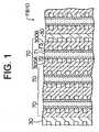
- a separator 300A, an anode 72, an electrolyte film 71, a cathode 73, and a separator 300Bare laminated in this order and a set of these materials is laminated in plural (3 sets in FIG. 1 ) wherein a cooling plate 30 is inserted every lamination of the set.
- a combination of three unit cells 70 having such a structure and the cooling plate 30is laminated in plural, for example, 100 sets.
- the cooling plate 30is formed of the same material as those of the separators 300A, 300B and serves to control the temperature of a fuel cell FB10 by supplying and withdrawing external cooling water.
- FIG. 2is a plan view of the separator 300A of this example.
- FIG. 3is a perspective view of the half part of the separator 300A.
- the separator 300Ais formed as a square plate material in which square holes 301, 303 with a large size are formed in the vicinity of two opposite side edges respectively and square holes 305, 306, 307, 308 with a small size in the vicinity of other two side edges respectively.
- a stepped surface 311one step lower than the above peripheral plane is formed.
- projections 313which are a rectangular parallelepiped with 2 mm wide, 2 mm long and 1 mm high and are regularly arranged lattice-like are formed in plural.
- each of the rib pieces 355, 356has the same height of 1 mm as that of the projection 313, a width of 1mm and a length shorter than the side width of the stepped surface 311.
- the rib pieces 355, 356are formed such that directionally inverse ends 355a, 356a of the rib pieces 355, 356 respectively are connected to the peripheral plane of the separator 300A and the other ends 355b, 356b of the rib pieces 355, 356 respectively are positioned away from the peripheral plane at the given distance S.
- the distance Sis the same as the width W of a passage formed by the rib pieces 355, 356 in this example.
- the stepped surface 311is divided into three areas by the rib pieces 355, 356. These areas are communicated with each other and, as a consequence, one large wavy (bent form) passage is formed on the stepped surface 311. Both ends of the passage are connected to certain positions of the holes 305 and 308. Since no partitioned wall is not present between the ends of the passage and the holes 305, 308 respectively, the wavy passage is communicated with the holes 305, 308. As a result, fuel gas from the passage for supplying and exhausting fuel gas which passage comprises the holes 305, 308 is supplied to and exhausted from the above passage on the stepped surface 311.
- a combination of the rib pieces 355, 356, the stepped surface 311 and the surface of the anode 72forms a wavy passage (large passage) for fuel gas.
- a combination of the projections 313, the stepped surface 311 and the surface of the anode 72forms passages (small passages) for fuel gas which are branched in a plurality of directions.
- a stepped surface, projections and rib pieces(both not shown) having the same shapes as those of the stepped surface 311, the projections 313 and rib pieces 355, 356 respectively are formed.
- a combination of these stepped surface, projections, rib pieces and the surface of the cathode 73forms a passage of oxygen-containing gas. Oxygen-containing gas from the passage for supplying and exhausting oxygen-containing gas which passage has the hole 306, 307 is supplied to and exhausted from the passage of oxygen-containing gas.
- a wavy passage of fuel gasis formed between the holes 305 and 308 and plural projections 313 are formed in the passage.
- the formation of the rib pieces 355, 356ensures that the entire width of the passage communicated with the holes 305, 308 as the inlet and outlet of fuel gas is decreased.
- concentration polarizationcan be reduced by enhancing diffusibility of fuel gas.
- oxygen-containing gasthe same structure is made in which the concentration polarization can be reduced by enhancing diffusibility of fuel gas.
- the total length of the passageis elongated by forming the gas passage into the wavy shape. It is therefore possible to prevent the dry-up of the electrolyte film even if dry gas is used as the supply gas including the fuel gas and the oxygen-containing gas.
- dry gasincluding the fuel gas and the oxygen-containing gas.
- wateris created by an electrode reaction and there is the case where the drainage of the created water is excessive causing the electrolyte film to be dried-up.
- the total length of the passageis long, supply gas is gradually moistened as it goes forward and hence the electrolyte film 321 is prevented from being dried-up.
- the actions by which concentration polarization is reduced and the dry-up of the electrolyte film 321 is preventedcan improve the performance of the fuel cell FB10.
- the fuel cell of the examplewill be explained in comparison with fuel cells of related art technologies.
- the fuel cells in the related arttwo types, a fuel cell using a lattice type separator and a fuel cell (so-called serpentine type) provided with a wavy passage groove were prepared.
- two conditionswere adopted, specifically, a first condition using wet gas (the humidity of fuel gas and oxygen-containing gas were 100% and 90% respectively) and a second condition using dry gas (humidity of fuel gas and oxygen-containing gas were 100% and 30% respectively).
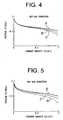
- FIG. 4is a graph showing the relation between voltage and current density when a fuel cell is operated in the first condition.
- FIG. 5is a graph showing the relation between voltage and current density when a fuel cell is operated in the second condition.
- the curve Aindicates the relation between voltage and current density for the fuel cell
- the curve Bindicates the relation between voltage and current density for the fuel cell of the lattice type of related art technologies
- the curve Cindicates the relation between voltage and current density for the fuel cell of the serpentine type of related art technologies.
- the fuel cell of the examplehad superior characteristics over all range of current density in contrast with the fuel cells of related art.
- a voltage reduction particularly at high current densities (above 0.5 A/cm 2 )is small.
- An improvement in the gas diffusibilitywas, thus, confirmed.
- the fuel cell of the examplehad superior characteristics over all range of current density in contrast with the fuel cells of related art.
- a voltage reductionis significantly smaller than that of the fuel cell of the lattice type of related art.
- the width (which corresponds to the distance S between the ends 355b, 356b of the rib pieces 355, 356 and the peripheral plane section) of the turning section in the wavy passage which section is formed by the rib pieces 355, 356is the same as the width W of the passage.
- the embodiment of the inventionadopts
- width S1 of the turning section from the first passageis narrower than the width W1 of the first passage and the width S2 of the turning section from the second passage is narrower than the width W2 of the second passage.
- the flow ratecan be further increased by the aforementioned device that the width of the passage is made narrower with a descent to a downstream side and the width of the turning section is made narrower than the width of the passage just before the turning section. This enhances diffusibility of supply gas whereby the improvement in drainage due to an increase in the flow rate can be more effected.
- the material for forming the separatorfine carbon which is made impermeable by compressing carbon is used. Different materials may be used.
- the separatormay be made from moulded carbon, burned carbon or a metal material. When a metal material is used to form the separator, it is desirable to select a metal having sufficient corrosion resistance.
- the surface of a metalmay be coated with a material having sufficient corrosion resistance.
- the production cost of a diegreatly differ depending on the size, number and accuracy of the rib. If a rib having the form used in the aforementioned embodiments is used, the production cost of the die can be considerably lowered since the number of the ribs may be low and the ribs may not be small.
Landscapes
- Life Sciences & Earth Sciences (AREA)
- Engineering & Computer Science (AREA)
- Manufacturing & Machinery (AREA)
- Sustainable Development (AREA)
- Sustainable Energy (AREA)
- Chemical & Material Sciences (AREA)
- Chemical Kinetics & Catalysis (AREA)
- Electrochemistry (AREA)
- General Chemical & Material Sciences (AREA)
- Fuel Cell (AREA)
Description
- The present invention relates to a polymer electrolyte fuel cell using a separator in contact with a pair of electrodes interposing an electrolyte film.
- A fuel cell is known as an apparatus for converting fuel energy directly to electric energy. The fuel cell is generally designed to be provided with a pair of electrodes with an electrolyte film interposed therebetween and to generate energy from the space between the pair of electrodes by an electrochemical reaction of fuel gas, e.g. hydrogen, and oxygen-containing gas. In this reaction, fuel gas is supplied to contact the surface of one of the electrodes and oxygen-containing gas is supplied to contact the surface of another electrode. Energy can be drawn from the fuel cell in a highly efficient manner as long as fuel gas and oxygen-containing gas are supplied.
FIG. 7 is a perspective view showing the configuration of astack structure 5 constituting a general fuel cell andFIG. 8 is an exploded perspective view showing the structure of aunit cell 10 as a basic unit of thestack structure 5 shown inFIG. 7 . In general, the fuel cell, for example, of a polymer electrolyte type is constituted of thestack structure 5 as shown inFIG. 7 . Thisstack structure 5 is produced by laminating a prescribed number ofunit cells 10, then disposingcollector plates insulating plates end plates collector plates output terminals stack structure 5.- In such a fuel cell, a member called a separator is provided which serves as a gas passage and a collector electrode to supply fuel gas and oxygen-containing gas to the electrode surface. A straight type separator provided with a plurality of linear passage grooves has been conventionally used. Serpentine type separators in which one passage groove is bent (disclosed in JP-A 7-263003) and lattice type separators in which plural projections are arranged and a passage is formed by a gap between these projections have also been known.
- The
unit cell 10 as a basic unit of thestack structure 5 ofFIG. 7 , as shown inFIG. 8 , includes a joint body (reaction electrode layer) 15 produced by sandwiching anelectrolyte film 11 between acathode 12 and an anode (not shown), andseparators reaction electrode layer 15. Among these parts, theseparators Plural ribs 22 formed of small projecting pieces are arranged on both surfaces 31 of the separators. - When these
separators separators 20A at the cathode side constitutes a passage for oxidizing gas supplied to thecathode 12. While therib 22 formed on thesurface 21 of theseparator 20B at the anode side constitutes a passage for fuel gas supplied to the anode (not shown). Meanwhile therib 22 formed on thesurface 21 opposite to the above surface of theseparator 20A constitutes a passage for fuel gas supplied to the anode (not shown) of another adjacent unit cell (not shown) and a rib (not shown) formed on the surface opposite to the above surface of theseparator 20B constitutes a passage for oxidizing gas supplied to a still another adjacent unit cell (not shown). One separator, therefore, supplies both types of gas to adjacent reaction electrodes and prevents mixture of both gases. - Oxidizing gas flowing through the oxidizing gas passage is distributed into the reaction electrode layer exposed to the oxidizing gas passage, and is supplied to the cathode of the reaction electrode layer. Likewise, fuel gas flowing through the fuel gas passage is distributed into the reaction electrode layer exposed to the fuel gas passage, and is supplied to the anode of the reaction electrode layer. As a consequence the respective gas is used in the
reaction electrode layer 15 for the electrochemical reaction to produce electromotive force. - Specifically, in the
reaction electrode layer 15, the reactions indicated by the formula (1) and the formula (2) proceed at the anode and cathode sides respectively and, on the whole, the reaction indicated by the formula (3) proceeds.
H2→2H++2e- (1)

- The serpentine type separator has a narrow gas inlet and a long gas passage, resulting in excellent gas diffusibility.
- However, in the known serpentine type separator, a partial pressure of gas in the gas passage is not constantly uniform. Accordingly there is the possibility that the performance of the fuel cell as a battery may be deteriorated.
- In the lattice type separator, even if one passage is clogged due to, for example, flooding or the like, specifically, condensation of water, gas and produced water can flow into other passages. So this type has excellent drainage as well as high diffusibility of gas. However, in the known lattice type separator, the passages are distributed in forward and backward directions leading to the possibility of insufficient gas flow rate. A deficiency in gas flow rate interrupts diffusion of gas, which causes concentration polarization, resulting in deteriorated performance of the fuel cell as a battery.
- In the case of using dry gas at a low humidity as the supply gas (fuel gas and oxygen-containing gas), drainage at the electrode side to which oxygen-containing gas is supplied is excessive. Hence there is the case where an electrolyte film is dried up. This gives rise to the possibility of deteriorating characteristics of the cell.
- An object of the present invention is to attain improved performance of the cell by eliminating interruption of gas diffusion and dry-up of the electrolyte film.
- The above object is attained by a fuel cell is produced by bringing an electrolyte film into contact with the surface of a first electrode so that the electrolyte film is interposed between the first electrode and an adjacent electrode and by defining a gas passage for supplying gas to the fuel cell, including a first manifold for supplying gas, which is formed at the corner of the separator; a second manifold for exhausting supply gas, which is formed at a position on having the features defined in
claim 1. FIG. 1 is a sectional view typically showing- a fuel cell of an example outside the scope of the present invention.
FIG. 2 is a plan view of a separator used in the example.FIG. 3 is a perspective view with a part in section showing the separator ofFIG. 6 .FIGS. 4 and 5 are graphs each showing the relation between voltage and current density of a fuel cell.FIG. 6 is a plan view of a separator used in an embodiment of the present invention.FIG. 7 is a perspective view showing the configuration of a stack structure constituting a conventional fuel cell.FIG. 8 is an exploded view showing a unit cell as a basic unit ofFIG. 7 .- A polymer electrolyte fuel cell (hereinafter simply called "fuel cell") of the present invention has a stack structure using a unit cell as a basic unit. In the example shown in
FIG. 1 , aseparator 300A, an anode 72, an electrolyte film 71, a cathode 73, and aseparator 300B are laminated in this order and a set of these materials is laminated in plural (3 sets inFIG. 1 ) wherein acooling plate 30 is inserted every lamination of the set. A combination of threeunit cells 70 having such a structure and thecooling plate 30 is laminated in plural, for example, 100 sets. Thecooling plate 30 is formed of the same material as those of theseparators FIG. 2 is a plan view of theseparator 300A of this example.FIG. 3 is a perspective view of the half part of theseparator 300A. As shown inFIGS. 2 and3 , theseparator 300A is formed as a square plate material in whichsquare holes square holes - The
holes holes 305, 308 with a small size which are opposed to each other on a diagonal line, when unit cells are laminated, form two passages for supplying and exhausting fuel gas which passages penetrate the fuel cell 310 in the direction of the lamination. The remainder twoholes - In further inside section than a peripheral plane of the
separator 300A in which plane theseholes stepped surface 311 one step lower than the above peripheral plane is formed. On thestepped surface 311,projections 313 which are a rectangular parallelepiped with 2 mm wide, 2 mm long and 1 mm high and are regularly arranged lattice-like are formed in plural. - On the
stepped surface 311, twolinear rib pieces stepped surface 311 into three equal parts are formed. Each of therib pieces projection 313, a width of 1mm and a length shorter than the side width of the steppedsurface 311. Therib pieces rib pieces separator 300A and the other ends 355b, 356b of therib pieces rib pieces - The stepped
surface 311 is divided into three areas by therib pieces surface 311. Both ends of the passage are connected to certain positions of theholes 305 and 308. Since no partitioned wall is not present between the ends of the passage and theholes 305, 308 respectively, the wavy passage is communicated with theholes 305, 308. As a result, fuel gas from the passage for supplying and exhausting fuel gas which passage comprises theholes 305, 308 is supplied to and exhausted from the above passage on the steppedsurface 311. - According to the
separator 300A having such a structure, in general, a combination of therib pieces surface 311 and the surface of the anode 72 forms a wavy passage (large passage) for fuel gas. In details, a combination of theprojections 313, the steppedsurface 311 and the surface of the anode 72 forms passages (small passages) for fuel gas which are branched in a plurality of directions. - Also on the other surface (the back surface in
FIG. 2 ) of theseparator 300A, a stepped surface, projections and rib pieces (both not shown) having the same shapes as those of the steppedsurface 311, theprojections 313 andrib pieces hole - As explained in detail, in the fuel cell 310 of this example, a wavy passage of fuel gas is formed between the
holes 305 and 308 andplural projections 313 are formed in the passage. The formation of therib pieces holes 305, 308 as the inlet and outlet of fuel gas is decreased. As the narrow width of the passage increases the flow velocity of fuel gas, concentration polarization can be reduced by enhancing diffusibility of fuel gas. Also in the case of oxygen-containing gas, the same structure is made in which the concentration polarization can be reduced by enhancing diffusibility of fuel gas. - In this fuel cell FB10, the total length of the passage is elongated by forming the gas passage into the wavy shape. It is therefore possible to prevent the dry-up of the electrolyte film even if dry gas is used as the supply gas including the fuel gas and the oxygen-containing gas. In general, on the cathode 323, water is created by an electrode reaction and there is the case where the drainage of the created water is excessive causing the electrolyte film to be dried-up. However in the fuel cell using the separator of this embodiment, if the total length of the passage is long, supply gas is gradually moistened as it goes forward and hence the electrolyte film 321 is prevented from being dried-up. Thus, the actions by which concentration polarization is reduced and the dry-up of the electrolyte film 321 is prevented can improve the performance of the fuel cell FB10.
- Next, the fuel cell of the example will be explained in comparison with fuel cells of related art technologies. Here, as the fuel cells in the related art, two types, a fuel cell using a lattice type separator and a fuel cell (so-called serpentine type) provided with a wavy passage groove were prepared. Also, as operating conditions, two conditions were adopted, specifically, a first condition using wet gas (the humidity of fuel gas and oxygen-containing gas were 100% and 90% respectively) and a second condition using dry gas (humidity of fuel gas and oxygen-containing gas were 100% and 30% respectively).
FIG. 4 is a graph showing the relation between voltage and current density when a fuel cell is operated in the first condition.FIG. 5 is a graph showing the relation between voltage and current density when a fuel cell is operated in the second condition. InFIGS. 4 and 5 , the curve A indicates the relation between voltage and current density for the fuel cell, the curve B indicates the relation between voltage and current density for the fuel cell of the lattice type of related art technologies and the curve C indicates the relation between voltage and current density for the fuel cell of the serpentine type of related art technologies.- As shown in
FIG. 4 , under the condition using the wet supply gas, the fuel cell of the example had superior characteristics over all range of current density in contrast with the fuel cells of related art. A voltage reduction particularly at high current densities (above 0.5 A/cm2) is small. An improvement in the gas diffusibility was, thus, confirmed. - As shown in
FIG. 5 , under the condition using the dry supply gas, the fuel cell of the example had superior characteristics over all range of current density in contrast with the fuel cells of related art. In particular, under the condition using dry gas, a voltage reduction is significantly smaller than that of the fuel cell of the lattice type of related art. An improvement in prevention of the dry-up of the electrolyte film 321 was, thus, confirmed. - In the example, the width (which corresponds to the distance S between the
ends rib pieces rib pieces - the structure shown in
FIG. 6 in which the widths W1, W2 and W3 structured by the rib pieces 455, 456 of a first passage, second passage and third passage respectively decrease every order (that is; these widths have the relation: W1 ≧ W2 ≧ W3) . It is noted that, in theseparator 500A inFIG. 6 , the width S1 of the turning section from the first passage is narrower than the width W1 of the first passage and the width S2 of the turning section from the second passage is narrower than the width W2 of the second passage. - The flow rate can be further increased by the aforementioned device that the width of the passage is made narrower with a descent to a downstream side and the width of the turning section is made narrower than the width of the passage just before the turning section. This enhances diffusibility of supply gas whereby the improvement in drainage due to an increase in the flow rate can be more effected. In the embodiment mentioned above, as the material for forming the separator, fine carbon which is made impermeable by compressing carbon is used. Different materials may be used. For instance, the separator may be made from moulded carbon, burned carbon or a metal material. When a metal material is used to form the separator, it is desirable to select a metal having sufficient corrosion resistance. Alternatively, the surface of a metal may be coated with a material having sufficient corrosion resistance. Particularly when the separator is formed from a metal material, the production cost of a die greatly differ depending on the size, number and accuracy of the rib. If a rib having the form used in the aforementioned embodiments is used, the production cost of the die can be considerably lowered since the number of the ribs may be low and the ribs may not be small.


Claims (2)
- A polymer electrolyte fuel cell having a joint body produced by interposing an electrolyte member between a pair of electrodes, and a pair of separators (500A) which hold the joint body, each of the separators (500A) comprising:a rib portion (555, 556) which divides an area which forms a fluid passage for fluid which flows through the separator, wherein the plurality of regions communicate with each other,characterized in that
the width (W1, W2, W3) of each region is different, the width (W1) of the regions near an inlet portion of the fluid being wider than the width (W3) of the regions near an outlet portion of the fluid; and
each of the separators (500A) has a plurality of projections projecting from a bottom of the fluid passage to reach a surface of the corresponding electrode, the projections formed in one separator (500A) facing the projections formed in the other separator (500A) via the joint body. - A polymer electrolyte fuel cell according to claim 1, wherein the separator (500A) is made of a gas-impermeable electroconductive material.
Applications Claiming Priority (4)
| Application Number | Priority Date | Filing Date | Title |
|---|---|---|---|
| JP36512997AJP4061684B2 (en) | 1997-12-18 | 1997-12-18 | Fuel cell |
| JP10100453AJPH11283639A (en) | 1998-03-27 | 1998-03-27 | Fuel cell separator and fuel cell |
| JP10189926AJP2000012050A (en) | 1998-06-18 | 1998-06-18 | Gas separator device and fuel cell using the same |
| EP98124043AEP0924785B1 (en) | 1997-12-18 | 1998-12-17 | Fuel cell and bipolar separator for the same |
Related Parent Applications (2)
| Application Number | Title | Priority Date | Filing Date |
|---|---|---|---|
| EP98124043.5Division | 1998-12-17 | ||
| EP98124043ADivisionEP0924785B1 (en) | 1997-12-18 | 1998-12-17 | Fuel cell and bipolar separator for the same |
Publications (3)
| Publication Number | Publication Date |
|---|---|
| EP1722436A2 EP1722436A2 (en) | 2006-11-15 |
| EP1722436A3 EP1722436A3 (en) | 2009-04-08 |
| EP1722436B1true EP1722436B1 (en) | 2011-04-27 |
Family
ID=27309224
Family Applications (3)
| Application Number | Title | Priority Date | Filing Date |
|---|---|---|---|
| EP06120142AExpired - LifetimeEP1722436B1 (en) | 1997-12-18 | 1998-12-17 | Polymer electrolyte fuel cell and bipolar separator for the same |
| EP98124043AExpired - LifetimeEP0924785B1 (en) | 1997-12-18 | 1998-12-17 | Fuel cell and bipolar separator for the same |
| EP00127081AExpired - LifetimeEP1100140B1 (en) | 1997-12-18 | 1998-12-17 | Fuel cell and separator for the same |
Family Applications After (2)
| Application Number | Title | Priority Date | Filing Date |
|---|---|---|---|
| EP98124043AExpired - LifetimeEP0924785B1 (en) | 1997-12-18 | 1998-12-17 | Fuel cell and bipolar separator for the same |
| EP00127081AExpired - LifetimeEP1100140B1 (en) | 1997-12-18 | 1998-12-17 | Fuel cell and separator for the same |
Country Status (4)
| Country | Link |
|---|---|
| US (1) | US6245453B1 (en) |
| EP (3) | EP1722436B1 (en) |
| CA (1) | CA2256276C (en) |
| DE (3) | DE69836191T2 (en) |
Families Citing this family (50)
| Publication number | Priority date | Publication date | Assignee | Title |
|---|---|---|---|---|
| JP4074061B2 (en)* | 1998-09-04 | 2008-04-09 | 株式会社東芝 | Polymer electrolyte fuel cell system |
| JP2000277132A (en)* | 1999-03-25 | 2000-10-06 | Sanyo Electric Co Ltd | Fuel cell |
| AT407589B (en)* | 1999-11-03 | 2001-04-25 | Vaillant Gmbh | Fuel cell |
| US7153602B2 (en)* | 2000-05-08 | 2006-12-26 | Honda Giken Kogyo Kabushiki Kaisha | Fuel cell assembly |
| KR100697253B1 (en) | 2000-05-08 | 2007-03-21 | 혼다 기켄 고교 가부시키가이샤 | Fuel cell |
| US6586128B1 (en) | 2000-05-09 | 2003-07-01 | Ballard Power Systems, Inc. | Differential pressure fluid flow fields for fuel cells |
| US6509113B2 (en)* | 2000-12-15 | 2003-01-21 | Delphi Technologies, Inc. | Fluid distribution surface for solid oxide fuel cells |
| KR100625698B1 (en)* | 2000-12-30 | 2006-09-20 | 주식회사 엘지이아이 | Separator Structure of Fuel Cell |
| AU2002254223A1 (en)* | 2001-02-27 | 2002-09-12 | E.I. Dupont De Nemours And Company | Fluid flow field plates for electrochemical devices |
| DE10155349C2 (en)* | 2001-11-02 | 2003-11-20 | Fraunhofer Ges Forschung | Micro fuel cell system and method for its production |
| US7097931B2 (en) | 2002-02-27 | 2006-08-29 | E. I. Du Pont De Nemours And Company | Fluid flow-fields for electrochemical devices |
| AU2003238801A1 (en)* | 2002-05-31 | 2003-12-19 | Lynntech, Inc. | Electrochemical cell and bipolar assembly for an electrochemical cell |
| DE10232871A1 (en)* | 2002-07-19 | 2004-02-05 | Daimlerchrysler Ag | Fuel cell with internal gas regulation has distributor structure for feed channels for reagents of anode and/or cathode divided into at least two fields, each with input and output ports for reagents |
| WO2004038840A1 (en)* | 2002-10-28 | 2004-05-06 | Honda Motor Co., Ltd. | Fuel cell |
| US20040131915A1 (en)* | 2002-11-28 | 2004-07-08 | Scott Sherman | Solid oxide fuel cell stack |
| US7405019B2 (en)* | 2003-03-14 | 2008-07-29 | Matsushita Electric Industrial Co., Ltd. | Polymer electrolyte fuel cell |
| US7261966B2 (en)* | 2003-06-30 | 2007-08-28 | Zongshen Pem Power Systems Inc. | Apparatus and method for conducting fluid in a fuel cell and fuel cell employing same |
| US20060246341A1 (en)* | 2003-08-29 | 2006-11-02 | Joerissen Ludwig | Gas distribution panel for a fuel cell and gas distribution panel containing a fuel cell |
| US7462415B2 (en)* | 2003-09-24 | 2008-12-09 | General Motors Corporation | Flow field plate arrangement for a fuel cell |
| US7655340B2 (en)* | 2004-01-16 | 2010-02-02 | Gm Global Technology Operations, Inc. | Ultra short high pressure gradient flow path flow field |
| CN100508266C (en)* | 2004-03-05 | 2009-07-01 | 尤米科尔股份公司及两合公司 | Membrane electrode unit |
| USD585826S1 (en) | 2004-06-24 | 2009-02-03 | Panasonic Corporation | Separator for fuel cell |
| US7604888B2 (en)* | 2004-07-30 | 2009-10-20 | Gm Global Technologies Operations, Inc. | Stamped PEM fuel cell plate manufacturing |
| US7261124B2 (en)* | 2004-09-10 | 2007-08-28 | General Motors Corporation | Bipolar plate channel structure with knobs for the improvement of water management in particular on the cathode side of a fuel cell |
| JP4854237B2 (en)* | 2004-10-22 | 2012-01-18 | 日産自動車株式会社 | Solid oxide fuel cell and stack structure |
| US20060093891A1 (en)* | 2004-11-02 | 2006-05-04 | General Electric Company | Flow field design for high fuel utilization fuel cells |
| WO2006054756A1 (en) | 2004-11-16 | 2006-05-26 | Toyota Jidosha Kabushiki Kaisha | Fuel cell |
| WO2006067971A2 (en)* | 2004-12-21 | 2006-06-29 | Nissan Motor Co., Ltd. | Startup method for fuel cell stack structure, temperature control method for fuel cell stack structure, and fuel cell stack structure |
| CA2540773C (en) | 2005-03-25 | 2011-10-18 | Honda Motor Co., Ltd. | Fuel cell with gas separator which discharges retained water |
| JP4611194B2 (en)* | 2005-12-28 | 2011-01-12 | 本田技研工業株式会社 | Fuel cell and fuel cell stack |
| CN100416900C (en)* | 2006-04-29 | 2008-09-03 | 中山大学 | A proton exchange membrane fuel cell plate containing combined flow channels |
| US7951501B2 (en)* | 2006-08-17 | 2011-05-31 | The Trustees Of Princeton University | Fuel cell system and method for controlling current |
| JP5332092B2 (en) | 2006-09-11 | 2013-11-06 | トヨタ自動車株式会社 | Fuel cell |
| ES2315126B1 (en)* | 2006-10-06 | 2010-01-08 | Consejo Superior Investig. Cientificas | BIPOLAR PLATE FOR HOMOGENIC DISTRIBUTION OF FLOW IN FUEL BATTERIES. |
| JP2008152979A (en)* | 2006-12-14 | 2008-07-03 | Toyota Motor Corp | Fuel cell and fuel cell stack |
| JP2008243788A (en)* | 2007-02-28 | 2008-10-09 | Toyota Motor Corp | Fuel cell |
| WO2008104860A1 (en)* | 2007-02-28 | 2008-09-04 | Toyota Jidosha Kabushiki Kaisha | Fuel cell |
| CN101308931B (en)* | 2007-05-17 | 2011-06-29 | 扬光绿能股份有限公司 | Runner plate module for fuel cell |
| JP5907278B2 (en)* | 2012-03-15 | 2016-04-26 | 日産自動車株式会社 | Fuel cell |
| US9644277B2 (en) | 2012-08-14 | 2017-05-09 | Loop Energy Inc. | Reactant flow channels for electrolyzer applications |
| GB201503750D0 (en) | 2012-08-14 | 2015-04-22 | Powerdisc Dev Corp Ltd | Fuel cells components, stacks and modular fuel cell systems |
| CA3123208C (en) | 2012-08-14 | 2023-10-03 | Loop Energy Inc. | Fuel cell flow channels and flow fields |
| CN107530595B (en)* | 2015-04-24 | 2020-12-11 | 懿华水处理技术有限责任公司 | Structures for Standardized Multiplanar Flow Distribution within Electrochemical Separation Systems |
| CA3016102A1 (en) | 2016-03-22 | 2017-09-28 | Loop Energy Inc. | Fuel cell flow field design for thermal management |
| CN111108637A (en)* | 2017-08-28 | 2020-05-05 | 百拉得动力系统公司 | Flow field plates for electrochemical fuel cells |
| CN109616685A (en)* | 2018-12-11 | 2019-04-12 | 中国科学院大连化学物理研究所 | A fuel cell bipolar plate structure |
| NL2022354B1 (en)* | 2019-01-08 | 2020-08-13 | Hyet Holding B V | Flow field plate and compressor comprising such plate |
| CN112242536B (en)* | 2019-07-16 | 2022-03-18 | 未势能源科技有限公司 | Bipolar plate structure for fuel cell, fuel cell and fuel cell vehicle |
| CN112873930B (en)* | 2021-01-11 | 2022-07-29 | 华迪钢业集团有限公司 | Stainless steel seamless steel pipe and processing technology thereof |
| CN116137342B (en)* | 2021-11-17 | 2025-09-05 | 上海清能合睿兹新能源科技有限公司 | Fuel cell stack positioning device and stacking system |
Family Cites Families (34)
| Publication number | Priority date | Publication date | Assignee | Title |
|---|---|---|---|---|
| US3801374A (en)* | 1969-01-08 | 1974-04-02 | United Aircraft Corp | Graphite and vinylidene fluoride structures for fuel cells |
| JPS56134473A (en) | 1980-03-25 | 1981-10-21 | Toshiba Corp | Unit cell for fuel cell |
| JPS57208077A (en)* | 1981-06-17 | 1982-12-21 | Hitachi Ltd | Fuel cell |
| JPS5830074A (en)* | 1981-08-14 | 1983-02-22 | Hitachi Ltd | Fuel cell |
| JPS58131667A (en)* | 1982-01-29 | 1983-08-05 | Hitachi Ltd | Fuel cell |
| JPS58166658A (en) | 1982-03-27 | 1983-10-01 | Hitachi Ltd | Fuel cell |
| US4649091A (en)* | 1982-06-23 | 1987-03-10 | United Technologies Corporation | Fuel cell battery with improved membrane cooling |
| JPS60133665A (en)* | 1983-12-21 | 1985-07-16 | Sanyo Electric Co Ltd | Gas separation plate for fuel cell |
| JPS60243974A (en)* | 1984-05-17 | 1985-12-03 | Sanyo Electric Co Ltd | Fuel cell gas separation plate |
| JPS61256568A (en) | 1985-05-09 | 1986-11-14 | Toshiba Corp | Fuel cell |
| JPS61273872A (en)* | 1985-05-29 | 1986-12-04 | Fuji Electric Co Ltd | Fuel cell |
| JPS6276260A (en)* | 1985-09-30 | 1987-04-08 | Ishikawajima Harima Heavy Ind Co Ltd | Separator for fuel cells |
| US4743518A (en)* | 1987-03-04 | 1988-05-10 | International Fuel Cells Corporation | Corrosion resistant fuel cell structure |
| JPS6463271A (en) | 1987-09-02 | 1989-03-09 | Hitachi Ltd | Fuel cell |
| JPH01151163A (en)* | 1987-12-07 | 1989-06-13 | Fuji Electric Co Ltd | Fuel cell |
| JPH0240862A (en)* | 1988-07-29 | 1990-02-09 | Hitachi Ltd | Internal reforming type fuel cell |
| JPH02155171A (en) | 1988-12-08 | 1990-06-14 | Fuji Electric Co Ltd | Fuel cell |
| US4910100A (en)* | 1989-07-21 | 1990-03-20 | Fuji Electric Co., Ltd. | Solid electrolyte fuel cell |
| JPH03266365A (en)* | 1990-03-15 | 1991-11-27 | Nkk Corp | Solid oxide fuel cell separator |
| JPH03289057A (en)* | 1990-04-06 | 1991-12-19 | Hitachi Ltd | fuel cell separator |
| JPH0521076A (en)* | 1991-07-08 | 1993-01-29 | Sanyo Electric Co Ltd | Fuel battery |
| JPH05159790A (en)* | 1991-12-05 | 1993-06-25 | Tokyo Gas Co Ltd | Solid oxide fuel cell |
| US5541015A (en)* | 1992-05-12 | 1996-07-30 | Sanyo Electric Co., Ltd. | Fuel cell using a separate gas cooling method |
| JPH0689730A (en)* | 1992-09-10 | 1994-03-29 | Fuji Electric Co Ltd | Solid polymer electrolyte fuel cell |
| JPH07230815A (en)* | 1994-02-18 | 1995-08-29 | Tokyo Electric Power Co Inc:The | Plate type solid electrolyte electrochemical cell |
| JP3382708B2 (en) | 1994-03-25 | 2003-03-04 | 三菱重工業株式会社 | Gas separator for solid polymer electrolyte fuel cells |
| JP3219600B2 (en)* | 1994-07-21 | 2001-10-15 | 日立造船株式会社 | Solid oxide fuel cell |
| JPH08138692A (en)* | 1994-11-04 | 1996-05-31 | Toyota Motor Corp | Fuel cell |
| JPH08138696A (en)* | 1994-11-07 | 1996-05-31 | Toyota Motor Corp | Fuel cell |
| JP3555215B2 (en)* | 1995-01-26 | 2004-08-18 | トヨタ自動車株式会社 | Method of manufacturing fuel cell and flow path forming member used therein |
| WO1997033331A1 (en)* | 1996-03-06 | 1997-09-12 | Siemens Aktiengesellschaft | Fuel cell with internal moistening |
| US5686199A (en)* | 1996-05-07 | 1997-11-11 | Alliedsignal Inc. | Flow field plate for use in a proton exchange membrane fuel cell |
| JP3713912B2 (en)* | 1996-08-08 | 2005-11-09 | アイシン精機株式会社 | Fuel cell gas passage plate |
| EP0967675B1 (en)* | 1998-06-26 | 2010-01-20 | Toyota Jidosha Kabushiki Kaisha | Fuel cell and method for distributing gas in fuel cell |
- 1998
- 1998-12-17EPEP06120142Apatent/EP1722436B1/ennot_activeExpired - Lifetime
- 1998-12-17DEDE69836191Tpatent/DE69836191T2/ennot_activeExpired - Fee Related
- 1998-12-17DEDE69831615Tpatent/DE69831615T2/ennot_activeExpired - Fee Related
- 1998-12-17DEDE69842244Tpatent/DE69842244D1/ennot_activeExpired - Lifetime
- 1998-12-17CACA002256276Apatent/CA2256276C/ennot_activeExpired - Fee Related
- 1998-12-17EPEP98124043Apatent/EP0924785B1/ennot_activeExpired - Lifetime
- 1998-12-17EPEP00127081Apatent/EP1100140B1/ennot_activeExpired - Lifetime
- 1998-12-18USUS09/216,778patent/US6245453B1/ennot_activeExpired - Fee Related
Also Published As
| Publication number | Publication date |
|---|---|
| EP1100140A3 (en) | 2003-12-03 |
| DE69831615T2 (en) | 2006-06-22 |
| EP1100140A2 (en) | 2001-05-16 |
| EP1722436A3 (en) | 2009-04-08 |
| EP0924785A2 (en) | 1999-06-23 |
| EP1722436A2 (en) | 2006-11-15 |
| EP1100140B1 (en) | 2005-09-14 |
| CA2256276A1 (en) | 1999-06-18 |
| US6245453B1 (en) | 2001-06-12 |
| CA2256276C (en) | 2003-04-08 |
| DE69831615D1 (en) | 2005-10-20 |
| EP0924785B1 (en) | 2006-10-18 |
| DE69842244D1 (en) | 2011-06-09 |
| EP0924785A3 (en) | 2003-12-17 |
| DE69836191D1 (en) | 2006-11-30 |
| DE69836191T2 (en) | 2007-08-30 |
Similar Documents
| Publication | Publication Date | Title |
|---|---|---|
| EP1722436B1 (en) | Polymer electrolyte fuel cell and bipolar separator for the same | |
| KR101693993B1 (en) | Bipolar plate for fuel cell | |
| US7867666B2 (en) | Fuel cell with triangular buffers for reactant gas and coolant | |
| KR100549683B1 (en) | Solid polymer fuel cell assembly, fuel cell stack, and reaction gas supply method of fuel cell | |
| JP4245091B2 (en) | Fuel cell | |
| US7378167B2 (en) | Separator passage structure of fuel cell | |
| US7638227B2 (en) | Fuel cell having stack structure | |
| CA2880560C (en) | Fuel cell system with cathode flow field variation | |
| US7572537B2 (en) | Fuel cell and separator for the same | |
| US20050158604A1 (en) | Fuel cell stack | |
| US7261124B2 (en) | Bipolar plate channel structure with knobs for the improvement of water management in particular on the cathode side of a fuel cell | |
| JP4232286B2 (en) | Fuel cell | |
| JP3509180B2 (en) | Fuel cell | |
| WO2024037530A1 (en) | Fuel cell | |
| JP2003217615A (en) | Fuel cell separator | |
| JP4727910B2 (en) | Fuel cell | |
| JP4344584B2 (en) | Fuel cell | |
| JP4197514B2 (en) | Fuel cell system and stack | |
| JPH07161365A (en) | Fuel cell separator | |
| CN113948731A (en) | Multi-perforated plates for fuel cell separators and fuel cells | |
| JP2005339901A (en) | Fuel cell and fuel cell separator | |
| JP2004192971A (en) | Fuel cell separator | |
| JP2002289219A (en) | Polymer electrolyte fuel cell |
Legal Events
| Date | Code | Title | Description |
|---|---|---|---|
| PUAI | Public reference made under article 153(3) epc to a published international application that has entered the european phase | Free format text:ORIGINAL CODE: 0009012 | |
| 17P | Request for examination filed | Effective date:20060905 | |
| AC | Divisional application: reference to earlier application | Ref document number:0924785 Country of ref document:EP Kind code of ref document:P | |
| AK | Designated contracting states | Kind code of ref document:A2 Designated state(s):DE FR GB IT | |
| PUAL | Search report despatched | Free format text:ORIGINAL CODE: 0009013 | |
| AK | Designated contracting states | Kind code of ref document:A3 Designated state(s):DE FR GB IT | |
| RIC1 | Information provided on ipc code assigned before grant | Ipc:H01M 8/02 20060101AFI20090305BHEP | |
| AKX | Designation fees paid | Designated state(s):DE FR GB IT | |
| 17Q | First examination report despatched | Effective date:20100203 | |
| RTI1 | Title (correction) | Free format text:POLYMER ELECTROLYTE FUEL CELL AND BIPOLAR SEPARATOR FOR THE SAME | |
| GRAP | Despatch of communication of intention to grant a patent | Free format text:ORIGINAL CODE: EPIDOSNIGR1 | |
| GRAS | Grant fee paid | Free format text:ORIGINAL CODE: EPIDOSNIGR3 | |
| GRAA | (expected) grant | Free format text:ORIGINAL CODE: 0009210 | |
| AC | Divisional application: reference to earlier application | Ref document number:0924785 Country of ref document:EP Kind code of ref document:P | |
| AK | Designated contracting states | Kind code of ref document:B1 Designated state(s):DE FR GB IT | |
| REG | Reference to a national code | Ref country code:GB Ref legal event code:FG4D | |
| REF | Corresponds to: | Ref document number:69842244 Country of ref document:DE Date of ref document:20110609 Kind code of ref document:P | |
| REG | Reference to a national code | Ref country code:DE Ref legal event code:R096 Ref document number:69842244 Country of ref document:DE Effective date:20110609 | |
| PGFP | Annual fee paid to national office [announced via postgrant information from national office to epo] | Ref country code:FR Payment date:20111219 Year of fee payment:14 | |
| PLBE | No opposition filed within time limit | Free format text:ORIGINAL CODE: 0009261 | |
| STAA | Information on the status of an ep patent application or granted ep patent | Free format text:STATUS: NO OPPOSITION FILED WITHIN TIME LIMIT | |
| 26N | No opposition filed | Effective date:20120130 | |
| REG | Reference to a national code | Ref country code:DE Ref legal event code:R097 Ref document number:69842244 Country of ref document:DE Effective date:20120130 | |
| REG | Reference to a national code | Ref country code:GB Ref legal event code:746 Effective date:20120917 | |
| REG | Reference to a national code | Ref country code:DE Ref legal event code:R084 Ref document number:69842244 Country of ref document:DE Effective date:20120924 | |
| GBPC | Gb: european patent ceased through non-payment of renewal fee | Effective date:20121217 | |
| REG | Reference to a national code | Ref country code:FR Ref legal event code:ST Effective date:20130830 | |
| REG | Reference to a national code | Ref country code:DE Ref legal event code:R119 Ref document number:69842244 Country of ref document:DE Effective date:20130702 | |
| PG25 | Lapsed in a contracting state [announced via postgrant information from national office to epo] | Ref country code:DE Free format text:LAPSE BECAUSE OF NON-PAYMENT OF DUE FEES Effective date:20130702 | |
| PG25 | Lapsed in a contracting state [announced via postgrant information from national office to epo] | Ref country code:GB Free format text:LAPSE BECAUSE OF NON-PAYMENT OF DUE FEES Effective date:20121217 Ref country code:FR Free format text:LAPSE BECAUSE OF NON-PAYMENT OF DUE FEES Effective date:20130102 | |
| PG25 | Lapsed in a contracting state [announced via postgrant information from national office to epo] | Ref country code:IT Free format text:LAPSE BECAUSE OF NON-PAYMENT OF DUE FEES Effective date:20121217 |