EP1721583A2 - Implant for the insertion between the vertebraes and operation tool for using the implant - Google Patents
Implant for the insertion between the vertebraes and operation tool for using the implantDownload PDFInfo
- Publication number
- EP1721583A2 EP1721583A2EP06016301AEP06016301AEP1721583A2EP 1721583 A2EP1721583 A2EP 1721583A2EP 06016301 AEP06016301 AEP 06016301AEP 06016301 AEP06016301 AEP 06016301AEP 1721583 A2EP1721583 A2EP 1721583A2
- Authority
- EP
- European Patent Office
- Prior art keywords
- implant
- implant part
- surgical instrument
- ring
- threaded ring
- Prior art date
- Legal status (The legal status is an assumption and is not a legal conclusion. Google has not performed a legal analysis and makes no representation as to the accuracy of the status listed.)
- Granted
Links
Images


Classifications
- A—HUMAN NECESSITIES
- A61—MEDICAL OR VETERINARY SCIENCE; HYGIENE
- A61F—FILTERS IMPLANTABLE INTO BLOOD VESSELS; PROSTHESES; DEVICES PROVIDING PATENCY TO, OR PREVENTING COLLAPSING OF, TUBULAR STRUCTURES OF THE BODY, e.g. STENTS; ORTHOPAEDIC, NURSING OR CONTRACEPTIVE DEVICES; FOMENTATION; TREATMENT OR PROTECTION OF EYES OR EARS; BANDAGES, DRESSINGS OR ABSORBENT PADS; FIRST-AID KITS
- A61F2/00—Filters implantable into blood vessels; Prostheses, i.e. artificial substitutes or replacements for parts of the body; Appliances for connecting them with the body; Devices providing patency to, or preventing collapsing of, tubular structures of the body, e.g. stents
- A61F2/02—Prostheses implantable into the body
- A61F2/30—Joints
- A61F2/46—Special tools for implanting artificial joints
- A61F2/4603—Special tools for implanting artificial joints for insertion or extraction of endoprosthetic joints or of accessories thereof
- A61F2/4611—Special tools for implanting artificial joints for insertion or extraction of endoprosthetic joints or of accessories thereof of spinal prostheses
- A—HUMAN NECESSITIES
- A61—MEDICAL OR VETERINARY SCIENCE; HYGIENE
- A61F—FILTERS IMPLANTABLE INTO BLOOD VESSELS; PROSTHESES; DEVICES PROVIDING PATENCY TO, OR PREVENTING COLLAPSING OF, TUBULAR STRUCTURES OF THE BODY, e.g. STENTS; ORTHOPAEDIC, NURSING OR CONTRACEPTIVE DEVICES; FOMENTATION; TREATMENT OR PROTECTION OF EYES OR EARS; BANDAGES, DRESSINGS OR ABSORBENT PADS; FIRST-AID KITS
- A61F2/00—Filters implantable into blood vessels; Prostheses, i.e. artificial substitutes or replacements for parts of the body; Appliances for connecting them with the body; Devices providing patency to, or preventing collapsing of, tubular structures of the body, e.g. stents
- A61F2/02—Prostheses implantable into the body
- A61F2/30—Joints
- A61F2/44—Joints for the spine, e.g. vertebrae, spinal discs
- A—HUMAN NECESSITIES
- A61—MEDICAL OR VETERINARY SCIENCE; HYGIENE
- A61F—FILTERS IMPLANTABLE INTO BLOOD VESSELS; PROSTHESES; DEVICES PROVIDING PATENCY TO, OR PREVENTING COLLAPSING OF, TUBULAR STRUCTURES OF THE BODY, e.g. STENTS; ORTHOPAEDIC, NURSING OR CONTRACEPTIVE DEVICES; FOMENTATION; TREATMENT OR PROTECTION OF EYES OR EARS; BANDAGES, DRESSINGS OR ABSORBENT PADS; FIRST-AID KITS
- A61F2/00—Filters implantable into blood vessels; Prostheses, i.e. artificial substitutes or replacements for parts of the body; Appliances for connecting them with the body; Devices providing patency to, or preventing collapsing of, tubular structures of the body, e.g. stents
- A61F2/02—Prostheses implantable into the body
- A61F2/30—Joints
- A61F2/46—Special tools for implanting artificial joints
- A61F2/4603—Special tools for implanting artificial joints for insertion or extraction of endoprosthetic joints or of accessories thereof
- A—HUMAN NECESSITIES
- A61—MEDICAL OR VETERINARY SCIENCE; HYGIENE
- A61F—FILTERS IMPLANTABLE INTO BLOOD VESSELS; PROSTHESES; DEVICES PROVIDING PATENCY TO, OR PREVENTING COLLAPSING OF, TUBULAR STRUCTURES OF THE BODY, e.g. STENTS; ORTHOPAEDIC, NURSING OR CONTRACEPTIVE DEVICES; FOMENTATION; TREATMENT OR PROTECTION OF EYES OR EARS; BANDAGES, DRESSINGS OR ABSORBENT PADS; FIRST-AID KITS
- A61F2/00—Filters implantable into blood vessels; Prostheses, i.e. artificial substitutes or replacements for parts of the body; Appliances for connecting them with the body; Devices providing patency to, or preventing collapsing of, tubular structures of the body, e.g. stents
- A61F2/02—Prostheses implantable into the body
- A61F2/28—Bones
- A61F2002/2835—Bone graft implants for filling a bony defect or an endoprosthesis cavity, e.g. by synthetic material or biological material
- A—HUMAN NECESSITIES
- A61—MEDICAL OR VETERINARY SCIENCE; HYGIENE
- A61F—FILTERS IMPLANTABLE INTO BLOOD VESSELS; PROSTHESES; DEVICES PROVIDING PATENCY TO, OR PREVENTING COLLAPSING OF, TUBULAR STRUCTURES OF THE BODY, e.g. STENTS; ORTHOPAEDIC, NURSING OR CONTRACEPTIVE DEVICES; FOMENTATION; TREATMENT OR PROTECTION OF EYES OR EARS; BANDAGES, DRESSINGS OR ABSORBENT PADS; FIRST-AID KITS
- A61F2/00—Filters implantable into blood vessels; Prostheses, i.e. artificial substitutes or replacements for parts of the body; Appliances for connecting them with the body; Devices providing patency to, or preventing collapsing of, tubular structures of the body, e.g. stents
- A61F2/02—Prostheses implantable into the body
- A61F2/30—Joints
- A61F2002/30001—Additional features of subject-matter classified in A61F2/28, A61F2/30 and subgroups thereof
- A61F2002/30316—The prosthesis having different structural features at different locations within the same prosthesis; Connections between prosthetic parts; Special structural features of bone or joint prostheses not otherwise provided for
- A61F2002/30329—Connections or couplings between prosthetic parts, e.g. between modular parts; Connecting elements
- A61F2002/30331—Connections or couplings between prosthetic parts, e.g. between modular parts; Connecting elements made by longitudinally pushing a protrusion into a complementarily-shaped recess, e.g. held by friction fit
- A61F2002/30362—Connections or couplings between prosthetic parts, e.g. between modular parts; Connecting elements made by longitudinally pushing a protrusion into a complementarily-shaped recess, e.g. held by friction fit with possibility of relative movement between the protrusion and the recess
- A61F2002/30369—Limited lateral translation of the protrusion within a larger recess
- A—HUMAN NECESSITIES
- A61—MEDICAL OR VETERINARY SCIENCE; HYGIENE
- A61F—FILTERS IMPLANTABLE INTO BLOOD VESSELS; PROSTHESES; DEVICES PROVIDING PATENCY TO, OR PREVENTING COLLAPSING OF, TUBULAR STRUCTURES OF THE BODY, e.g. STENTS; ORTHOPAEDIC, NURSING OR CONTRACEPTIVE DEVICES; FOMENTATION; TREATMENT OR PROTECTION OF EYES OR EARS; BANDAGES, DRESSINGS OR ABSORBENT PADS; FIRST-AID KITS
- A61F2/00—Filters implantable into blood vessels; Prostheses, i.e. artificial substitutes or replacements for parts of the body; Appliances for connecting them with the body; Devices providing patency to, or preventing collapsing of, tubular structures of the body, e.g. stents
- A61F2/02—Prostheses implantable into the body
- A61F2/30—Joints
- A61F2002/30001—Additional features of subject-matter classified in A61F2/28, A61F2/30 and subgroups thereof
- A61F2002/30316—The prosthesis having different structural features at different locations within the same prosthesis; Connections between prosthetic parts; Special structural features of bone or joint prostheses not otherwise provided for
- A61F2002/30329—Connections or couplings between prosthetic parts, e.g. between modular parts; Connecting elements
- A61F2002/30331—Connections or couplings between prosthetic parts, e.g. between modular parts; Connecting elements made by longitudinally pushing a protrusion into a complementarily-shaped recess, e.g. held by friction fit
- A61F2002/30362—Connections or couplings between prosthetic parts, e.g. between modular parts; Connecting elements made by longitudinally pushing a protrusion into a complementarily-shaped recess, e.g. held by friction fit with possibility of relative movement between the protrusion and the recess
- A61F2002/3037—Translation along the common longitudinal axis, e.g. piston
- A61F2002/30372—Translation along the common longitudinal axis, e.g. piston with additional means for limiting said translation
- A—HUMAN NECESSITIES
- A61—MEDICAL OR VETERINARY SCIENCE; HYGIENE
- A61F—FILTERS IMPLANTABLE INTO BLOOD VESSELS; PROSTHESES; DEVICES PROVIDING PATENCY TO, OR PREVENTING COLLAPSING OF, TUBULAR STRUCTURES OF THE BODY, e.g. STENTS; ORTHOPAEDIC, NURSING OR CONTRACEPTIVE DEVICES; FOMENTATION; TREATMENT OR PROTECTION OF EYES OR EARS; BANDAGES, DRESSINGS OR ABSORBENT PADS; FIRST-AID KITS
- A61F2/00—Filters implantable into blood vessels; Prostheses, i.e. artificial substitutes or replacements for parts of the body; Appliances for connecting them with the body; Devices providing patency to, or preventing collapsing of, tubular structures of the body, e.g. stents
- A61F2/02—Prostheses implantable into the body
- A61F2/30—Joints
- A61F2002/30001—Additional features of subject-matter classified in A61F2/28, A61F2/30 and subgroups thereof
- A61F2002/30316—The prosthesis having different structural features at different locations within the same prosthesis; Connections between prosthetic parts; Special structural features of bone or joint prostheses not otherwise provided for
- A61F2002/30329—Connections or couplings between prosthetic parts, e.g. between modular parts; Connecting elements
- A61F2002/30383—Connections or couplings between prosthetic parts, e.g. between modular parts; Connecting elements made by laterally inserting a protrusion, e.g. a rib into a complementarily-shaped groove
- A61F2002/3039—Connections or couplings between prosthetic parts, e.g. between modular parts; Connecting elements made by laterally inserting a protrusion, e.g. a rib into a complementarily-shaped groove with possibility of relative movement of the rib within the groove
- A61F2002/30397—Limited lateral translation of the rib within a larger groove
- A—HUMAN NECESSITIES
- A61—MEDICAL OR VETERINARY SCIENCE; HYGIENE
- A61F—FILTERS IMPLANTABLE INTO BLOOD VESSELS; PROSTHESES; DEVICES PROVIDING PATENCY TO, OR PREVENTING COLLAPSING OF, TUBULAR STRUCTURES OF THE BODY, e.g. STENTS; ORTHOPAEDIC, NURSING OR CONTRACEPTIVE DEVICES; FOMENTATION; TREATMENT OR PROTECTION OF EYES OR EARS; BANDAGES, DRESSINGS OR ABSORBENT PADS; FIRST-AID KITS
- A61F2/00—Filters implantable into blood vessels; Prostheses, i.e. artificial substitutes or replacements for parts of the body; Appliances for connecting them with the body; Devices providing patency to, or preventing collapsing of, tubular structures of the body, e.g. stents
- A61F2/02—Prostheses implantable into the body
- A61F2/30—Joints
- A61F2002/30001—Additional features of subject-matter classified in A61F2/28, A61F2/30 and subgroups thereof
- A61F2002/30316—The prosthesis having different structural features at different locations within the same prosthesis; Connections between prosthetic parts; Special structural features of bone or joint prostheses not otherwise provided for
- A61F2002/30329—Connections or couplings between prosthetic parts, e.g. between modular parts; Connecting elements
- A61F2002/30405—Connections or couplings between prosthetic parts, e.g. between modular parts; Connecting elements made by screwing complementary threads machined on the parts themselves
- A—HUMAN NECESSITIES
- A61—MEDICAL OR VETERINARY SCIENCE; HYGIENE
- A61F—FILTERS IMPLANTABLE INTO BLOOD VESSELS; PROSTHESES; DEVICES PROVIDING PATENCY TO, OR PREVENTING COLLAPSING OF, TUBULAR STRUCTURES OF THE BODY, e.g. STENTS; ORTHOPAEDIC, NURSING OR CONTRACEPTIVE DEVICES; FOMENTATION; TREATMENT OR PROTECTION OF EYES OR EARS; BANDAGES, DRESSINGS OR ABSORBENT PADS; FIRST-AID KITS
- A61F2/00—Filters implantable into blood vessels; Prostheses, i.e. artificial substitutes or replacements for parts of the body; Appliances for connecting them with the body; Devices providing patency to, or preventing collapsing of, tubular structures of the body, e.g. stents
- A61F2/02—Prostheses implantable into the body
- A61F2/30—Joints
- A61F2002/30001—Additional features of subject-matter classified in A61F2/28, A61F2/30 and subgroups thereof
- A61F2002/30316—The prosthesis having different structural features at different locations within the same prosthesis; Connections between prosthetic parts; Special structural features of bone or joint prostheses not otherwise provided for
- A61F2002/30329—Connections or couplings between prosthetic parts, e.g. between modular parts; Connecting elements
- A61F2002/30476—Connections or couplings between prosthetic parts, e.g. between modular parts; Connecting elements locked by an additional locking mechanism
- A61F2002/30492—Connections or couplings between prosthetic parts, e.g. between modular parts; Connecting elements locked by an additional locking mechanism using a locking pin
- A—HUMAN NECESSITIES
- A61—MEDICAL OR VETERINARY SCIENCE; HYGIENE
- A61F—FILTERS IMPLANTABLE INTO BLOOD VESSELS; PROSTHESES; DEVICES PROVIDING PATENCY TO, OR PREVENTING COLLAPSING OF, TUBULAR STRUCTURES OF THE BODY, e.g. STENTS; ORTHOPAEDIC, NURSING OR CONTRACEPTIVE DEVICES; FOMENTATION; TREATMENT OR PROTECTION OF EYES OR EARS; BANDAGES, DRESSINGS OR ABSORBENT PADS; FIRST-AID KITS
- A61F2/00—Filters implantable into blood vessels; Prostheses, i.e. artificial substitutes or replacements for parts of the body; Appliances for connecting them with the body; Devices providing patency to, or preventing collapsing of, tubular structures of the body, e.g. stents
- A61F2/02—Prostheses implantable into the body
- A61F2/30—Joints
- A61F2002/30001—Additional features of subject-matter classified in A61F2/28, A61F2/30 and subgroups thereof
- A61F2002/30316—The prosthesis having different structural features at different locations within the same prosthesis; Connections between prosthetic parts; Special structural features of bone or joint prostheses not otherwise provided for
- A61F2002/30329—Connections or couplings between prosthetic parts, e.g. between modular parts; Connecting elements
- A61F2002/30476—Connections or couplings between prosthetic parts, e.g. between modular parts; Connecting elements locked by an additional locking mechanism
- A61F2002/30495—Connections or couplings between prosthetic parts, e.g. between modular parts; Connecting elements locked by an additional locking mechanism using a locking ring
- A—HUMAN NECESSITIES
- A61—MEDICAL OR VETERINARY SCIENCE; HYGIENE
- A61F—FILTERS IMPLANTABLE INTO BLOOD VESSELS; PROSTHESES; DEVICES PROVIDING PATENCY TO, OR PREVENTING COLLAPSING OF, TUBULAR STRUCTURES OF THE BODY, e.g. STENTS; ORTHOPAEDIC, NURSING OR CONTRACEPTIVE DEVICES; FOMENTATION; TREATMENT OR PROTECTION OF EYES OR EARS; BANDAGES, DRESSINGS OR ABSORBENT PADS; FIRST-AID KITS
- A61F2/00—Filters implantable into blood vessels; Prostheses, i.e. artificial substitutes or replacements for parts of the body; Appliances for connecting them with the body; Devices providing patency to, or preventing collapsing of, tubular structures of the body, e.g. stents
- A61F2/02—Prostheses implantable into the body
- A61F2/30—Joints
- A61F2002/30001—Additional features of subject-matter classified in A61F2/28, A61F2/30 and subgroups thereof
- A61F2002/30316—The prosthesis having different structural features at different locations within the same prosthesis; Connections between prosthetic parts; Special structural features of bone or joint prostheses not otherwise provided for
- A61F2002/30329—Connections or couplings between prosthetic parts, e.g. between modular parts; Connecting elements
- A61F2002/30476—Connections or couplings between prosthetic parts, e.g. between modular parts; Connecting elements locked by an additional locking mechanism
- A61F2002/30507—Connections or couplings between prosthetic parts, e.g. between modular parts; Connecting elements locked by an additional locking mechanism using a threaded locking member, e.g. a locking screw or a set screw
- A—HUMAN NECESSITIES
- A61—MEDICAL OR VETERINARY SCIENCE; HYGIENE
- A61F—FILTERS IMPLANTABLE INTO BLOOD VESSELS; PROSTHESES; DEVICES PROVIDING PATENCY TO, OR PREVENTING COLLAPSING OF, TUBULAR STRUCTURES OF THE BODY, e.g. STENTS; ORTHOPAEDIC, NURSING OR CONTRACEPTIVE DEVICES; FOMENTATION; TREATMENT OR PROTECTION OF EYES OR EARS; BANDAGES, DRESSINGS OR ABSORBENT PADS; FIRST-AID KITS
- A61F2/00—Filters implantable into blood vessels; Prostheses, i.e. artificial substitutes or replacements for parts of the body; Appliances for connecting them with the body; Devices providing patency to, or preventing collapsing of, tubular structures of the body, e.g. stents
- A61F2/02—Prostheses implantable into the body
- A61F2/30—Joints
- A61F2002/30001—Additional features of subject-matter classified in A61F2/28, A61F2/30 and subgroups thereof
- A61F2002/30316—The prosthesis having different structural features at different locations within the same prosthesis; Connections between prosthetic parts; Special structural features of bone or joint prostheses not otherwise provided for
- A61F2002/30329—Connections or couplings between prosthetic parts, e.g. between modular parts; Connecting elements
- A61F2002/30518—Connections or couplings between prosthetic parts, e.g. between modular parts; Connecting elements with possibility of relative movement between the prosthetic parts
- A61F2002/30523—Connections or couplings between prosthetic parts, e.g. between modular parts; Connecting elements with possibility of relative movement between the prosthetic parts by means of meshing gear teeth
- A—HUMAN NECESSITIES
- A61—MEDICAL OR VETERINARY SCIENCE; HYGIENE
- A61F—FILTERS IMPLANTABLE INTO BLOOD VESSELS; PROSTHESES; DEVICES PROVIDING PATENCY TO, OR PREVENTING COLLAPSING OF, TUBULAR STRUCTURES OF THE BODY, e.g. STENTS; ORTHOPAEDIC, NURSING OR CONTRACEPTIVE DEVICES; FOMENTATION; TREATMENT OR PROTECTION OF EYES OR EARS; BANDAGES, DRESSINGS OR ABSORBENT PADS; FIRST-AID KITS
- A61F2/00—Filters implantable into blood vessels; Prostheses, i.e. artificial substitutes or replacements for parts of the body; Appliances for connecting them with the body; Devices providing patency to, or preventing collapsing of, tubular structures of the body, e.g. stents
- A61F2/02—Prostheses implantable into the body
- A61F2/30—Joints
- A61F2002/30001—Additional features of subject-matter classified in A61F2/28, A61F2/30 and subgroups thereof
- A61F2002/30316—The prosthesis having different structural features at different locations within the same prosthesis; Connections between prosthetic parts; Special structural features of bone or joint prostheses not otherwise provided for
- A61F2002/30535—Special structural features of bone or joint prostheses not otherwise provided for
- A61F2002/30537—Special structural features of bone or joint prostheses not otherwise provided for adjustable
- A61F2002/3055—Special structural features of bone or joint prostheses not otherwise provided for adjustable for adjusting length
- A—HUMAN NECESSITIES
- A61—MEDICAL OR VETERINARY SCIENCE; HYGIENE
- A61F—FILTERS IMPLANTABLE INTO BLOOD VESSELS; PROSTHESES; DEVICES PROVIDING PATENCY TO, OR PREVENTING COLLAPSING OF, TUBULAR STRUCTURES OF THE BODY, e.g. STENTS; ORTHOPAEDIC, NURSING OR CONTRACEPTIVE DEVICES; FOMENTATION; TREATMENT OR PROTECTION OF EYES OR EARS; BANDAGES, DRESSINGS OR ABSORBENT PADS; FIRST-AID KITS
- A61F2/00—Filters implantable into blood vessels; Prostheses, i.e. artificial substitutes or replacements for parts of the body; Appliances for connecting them with the body; Devices providing patency to, or preventing collapsing of, tubular structures of the body, e.g. stents
- A61F2/02—Prostheses implantable into the body
- A61F2/30—Joints
- A61F2002/30001—Additional features of subject-matter classified in A61F2/28, A61F2/30 and subgroups thereof
- A61F2002/30316—The prosthesis having different structural features at different locations within the same prosthesis; Connections between prosthetic parts; Special structural features of bone or joint prostheses not otherwise provided for
- A61F2002/30535—Special structural features of bone or joint prostheses not otherwise provided for
- A61F2002/30574—Special structural features of bone or joint prostheses not otherwise provided for with an integral complete or partial collar or flange
- A—HUMAN NECESSITIES
- A61—MEDICAL OR VETERINARY SCIENCE; HYGIENE
- A61F—FILTERS IMPLANTABLE INTO BLOOD VESSELS; PROSTHESES; DEVICES PROVIDING PATENCY TO, OR PREVENTING COLLAPSING OF, TUBULAR STRUCTURES OF THE BODY, e.g. STENTS; ORTHOPAEDIC, NURSING OR CONTRACEPTIVE DEVICES; FOMENTATION; TREATMENT OR PROTECTION OF EYES OR EARS; BANDAGES, DRESSINGS OR ABSORBENT PADS; FIRST-AID KITS
- A61F2/00—Filters implantable into blood vessels; Prostheses, i.e. artificial substitutes or replacements for parts of the body; Appliances for connecting them with the body; Devices providing patency to, or preventing collapsing of, tubular structures of the body, e.g. stents
- A61F2/02—Prostheses implantable into the body
- A61F2/30—Joints
- A61F2002/30001—Additional features of subject-matter classified in A61F2/28, A61F2/30 and subgroups thereof
- A61F2002/30316—The prosthesis having different structural features at different locations within the same prosthesis; Connections between prosthetic parts; Special structural features of bone or joint prostheses not otherwise provided for
- A61F2002/30535—Special structural features of bone or joint prostheses not otherwise provided for
- A61F2002/30593—Special structural features of bone or joint prostheses not otherwise provided for hollow
- A—HUMAN NECESSITIES
- A61—MEDICAL OR VETERINARY SCIENCE; HYGIENE
- A61F—FILTERS IMPLANTABLE INTO BLOOD VESSELS; PROSTHESES; DEVICES PROVIDING PATENCY TO, OR PREVENTING COLLAPSING OF, TUBULAR STRUCTURES OF THE BODY, e.g. STENTS; ORTHOPAEDIC, NURSING OR CONTRACEPTIVE DEVICES; FOMENTATION; TREATMENT OR PROTECTION OF EYES OR EARS; BANDAGES, DRESSINGS OR ABSORBENT PADS; FIRST-AID KITS
- A61F2/00—Filters implantable into blood vessels; Prostheses, i.e. artificial substitutes or replacements for parts of the body; Appliances for connecting them with the body; Devices providing patency to, or preventing collapsing of, tubular structures of the body, e.g. stents
- A61F2/02—Prostheses implantable into the body
- A61F2/30—Joints
- A61F2002/30001—Additional features of subject-matter classified in A61F2/28, A61F2/30 and subgroups thereof
- A61F2002/30316—The prosthesis having different structural features at different locations within the same prosthesis; Connections between prosthetic parts; Special structural features of bone or joint prostheses not otherwise provided for
- A61F2002/30535—Special structural features of bone or joint prostheses not otherwise provided for
- A61F2002/30594—Special structural features of bone or joint prostheses not otherwise provided for slotted, e.g. radial or meridian slot ending in a polar aperture, non-polar slots, horizontal or arcuate slots
- A—HUMAN NECESSITIES
- A61—MEDICAL OR VETERINARY SCIENCE; HYGIENE
- A61F—FILTERS IMPLANTABLE INTO BLOOD VESSELS; PROSTHESES; DEVICES PROVIDING PATENCY TO, OR PREVENTING COLLAPSING OF, TUBULAR STRUCTURES OF THE BODY, e.g. STENTS; ORTHOPAEDIC, NURSING OR CONTRACEPTIVE DEVICES; FOMENTATION; TREATMENT OR PROTECTION OF EYES OR EARS; BANDAGES, DRESSINGS OR ABSORBENT PADS; FIRST-AID KITS
- A61F2/00—Filters implantable into blood vessels; Prostheses, i.e. artificial substitutes or replacements for parts of the body; Appliances for connecting them with the body; Devices providing patency to, or preventing collapsing of, tubular structures of the body, e.g. stents
- A61F2/02—Prostheses implantable into the body
- A61F2/30—Joints
- A61F2002/30001—Additional features of subject-matter classified in A61F2/28, A61F2/30 and subgroups thereof
- A61F2002/30316—The prosthesis having different structural features at different locations within the same prosthesis; Connections between prosthetic parts; Special structural features of bone or joint prostheses not otherwise provided for
- A61F2002/30535—Special structural features of bone or joint prostheses not otherwise provided for
- A61F2002/30601—Special structural features of bone or joint prostheses not otherwise provided for telescopic
- A—HUMAN NECESSITIES
- A61—MEDICAL OR VETERINARY SCIENCE; HYGIENE
- A61F—FILTERS IMPLANTABLE INTO BLOOD VESSELS; PROSTHESES; DEVICES PROVIDING PATENCY TO, OR PREVENTING COLLAPSING OF, TUBULAR STRUCTURES OF THE BODY, e.g. STENTS; ORTHOPAEDIC, NURSING OR CONTRACEPTIVE DEVICES; FOMENTATION; TREATMENT OR PROTECTION OF EYES OR EARS; BANDAGES, DRESSINGS OR ABSORBENT PADS; FIRST-AID KITS
- A61F2/00—Filters implantable into blood vessels; Prostheses, i.e. artificial substitutes or replacements for parts of the body; Appliances for connecting them with the body; Devices providing patency to, or preventing collapsing of, tubular structures of the body, e.g. stents
- A61F2/02—Prostheses implantable into the body
- A61F2/30—Joints
- A61F2/30767—Special external or bone-contacting surface, e.g. coating for improving bone ingrowth
- A61F2/30771—Special external or bone-contacting surface, e.g. coating for improving bone ingrowth applied in original prostheses, e.g. holes or grooves
- A61F2002/30772—Apertures or holes, e.g. of circular cross section
- A61F2002/30774—Apertures or holes, e.g. of circular cross section internally-threaded
- A—HUMAN NECESSITIES
- A61—MEDICAL OR VETERINARY SCIENCE; HYGIENE
- A61F—FILTERS IMPLANTABLE INTO BLOOD VESSELS; PROSTHESES; DEVICES PROVIDING PATENCY TO, OR PREVENTING COLLAPSING OF, TUBULAR STRUCTURES OF THE BODY, e.g. STENTS; ORTHOPAEDIC, NURSING OR CONTRACEPTIVE DEVICES; FOMENTATION; TREATMENT OR PROTECTION OF EYES OR EARS; BANDAGES, DRESSINGS OR ABSORBENT PADS; FIRST-AID KITS
- A61F2/00—Filters implantable into blood vessels; Prostheses, i.e. artificial substitutes or replacements for parts of the body; Appliances for connecting them with the body; Devices providing patency to, or preventing collapsing of, tubular structures of the body, e.g. stents
- A61F2/02—Prostheses implantable into the body
- A61F2/30—Joints
- A61F2/30767—Special external or bone-contacting surface, e.g. coating for improving bone ingrowth
- A61F2/30771—Special external or bone-contacting surface, e.g. coating for improving bone ingrowth applied in original prostheses, e.g. holes or grooves
- A61F2002/30772—Apertures or holes, e.g. of circular cross section
- A61F2002/30777—Oblong apertures
- A—HUMAN NECESSITIES
- A61—MEDICAL OR VETERINARY SCIENCE; HYGIENE
- A61F—FILTERS IMPLANTABLE INTO BLOOD VESSELS; PROSTHESES; DEVICES PROVIDING PATENCY TO, OR PREVENTING COLLAPSING OF, TUBULAR STRUCTURES OF THE BODY, e.g. STENTS; ORTHOPAEDIC, NURSING OR CONTRACEPTIVE DEVICES; FOMENTATION; TREATMENT OR PROTECTION OF EYES OR EARS; BANDAGES, DRESSINGS OR ABSORBENT PADS; FIRST-AID KITS
- A61F2/00—Filters implantable into blood vessels; Prostheses, i.e. artificial substitutes or replacements for parts of the body; Appliances for connecting them with the body; Devices providing patency to, or preventing collapsing of, tubular structures of the body, e.g. stents
- A61F2/02—Prostheses implantable into the body
- A61F2/30—Joints
- A61F2/30767—Special external or bone-contacting surface, e.g. coating for improving bone ingrowth
- A61F2/30771—Special external or bone-contacting surface, e.g. coating for improving bone ingrowth applied in original prostheses, e.g. holes or grooves
- A61F2002/30772—Apertures or holes, e.g. of circular cross section
- A61F2002/30784—Plurality of holes
- A61F2002/30785—Plurality of holes parallel
- A—HUMAN NECESSITIES
- A61—MEDICAL OR VETERINARY SCIENCE; HYGIENE
- A61F—FILTERS IMPLANTABLE INTO BLOOD VESSELS; PROSTHESES; DEVICES PROVIDING PATENCY TO, OR PREVENTING COLLAPSING OF, TUBULAR STRUCTURES OF THE BODY, e.g. STENTS; ORTHOPAEDIC, NURSING OR CONTRACEPTIVE DEVICES; FOMENTATION; TREATMENT OR PROTECTION OF EYES OR EARS; BANDAGES, DRESSINGS OR ABSORBENT PADS; FIRST-AID KITS
- A61F2/00—Filters implantable into blood vessels; Prostheses, i.e. artificial substitutes or replacements for parts of the body; Appliances for connecting them with the body; Devices providing patency to, or preventing collapsing of, tubular structures of the body, e.g. stents
- A61F2/02—Prostheses implantable into the body
- A61F2/30—Joints
- A61F2/46—Special tools for implanting artificial joints
- A61F2/4603—Special tools for implanting artificial joints for insertion or extraction of endoprosthetic joints or of accessories thereof
- A61F2002/4625—Special tools for implanting artificial joints for insertion or extraction of endoprosthetic joints or of accessories thereof with relative movement between parts of the instrument during use
- A61F2002/4627—Special tools for implanting artificial joints for insertion or extraction of endoprosthetic joints or of accessories thereof with relative movement between parts of the instrument during use with linear motion along or rotating motion about the instrument axis or the implantation direction, e.g. telescopic, along a guiding rod, screwing inside the instrument
- A—HUMAN NECESSITIES
- A61—MEDICAL OR VETERINARY SCIENCE; HYGIENE
- A61F—FILTERS IMPLANTABLE INTO BLOOD VESSELS; PROSTHESES; DEVICES PROVIDING PATENCY TO, OR PREVENTING COLLAPSING OF, TUBULAR STRUCTURES OF THE BODY, e.g. STENTS; ORTHOPAEDIC, NURSING OR CONTRACEPTIVE DEVICES; FOMENTATION; TREATMENT OR PROTECTION OF EYES OR EARS; BANDAGES, DRESSINGS OR ABSORBENT PADS; FIRST-AID KITS
- A61F2/00—Filters implantable into blood vessels; Prostheses, i.e. artificial substitutes or replacements for parts of the body; Appliances for connecting them with the body; Devices providing patency to, or preventing collapsing of, tubular structures of the body, e.g. stents
- A61F2/02—Prostheses implantable into the body
- A61F2/30—Joints
- A61F2/46—Special tools for implanting artificial joints
- A61F2002/4631—Special tools for implanting artificial joints the prosthesis being specially adapted for being cemented
- A—HUMAN NECESSITIES
- A61—MEDICAL OR VETERINARY SCIENCE; HYGIENE
- A61F—FILTERS IMPLANTABLE INTO BLOOD VESSELS; PROSTHESES; DEVICES PROVIDING PATENCY TO, OR PREVENTING COLLAPSING OF, TUBULAR STRUCTURES OF THE BODY, e.g. STENTS; ORTHOPAEDIC, NURSING OR CONTRACEPTIVE DEVICES; FOMENTATION; TREATMENT OR PROTECTION OF EYES OR EARS; BANDAGES, DRESSINGS OR ABSORBENT PADS; FIRST-AID KITS
- A61F2/00—Filters implantable into blood vessels; Prostheses, i.e. artificial substitutes or replacements for parts of the body; Appliances for connecting them with the body; Devices providing patency to, or preventing collapsing of, tubular structures of the body, e.g. stents
- A61F2/02—Prostheses implantable into the body
- A61F2/30—Joints
- A61F2/46—Special tools for implanting artificial joints
- A61F2002/4632—Special tools for implanting artificial joints using computer-controlled surgery, e.g. robotic surgery
- A—HUMAN NECESSITIES
- A61—MEDICAL OR VETERINARY SCIENCE; HYGIENE
- A61F—FILTERS IMPLANTABLE INTO BLOOD VESSELS; PROSTHESES; DEVICES PROVIDING PATENCY TO, OR PREVENTING COLLAPSING OF, TUBULAR STRUCTURES OF THE BODY, e.g. STENTS; ORTHOPAEDIC, NURSING OR CONTRACEPTIVE DEVICES; FOMENTATION; TREATMENT OR PROTECTION OF EYES OR EARS; BANDAGES, DRESSINGS OR ABSORBENT PADS; FIRST-AID KITS
- A61F2220/00—Fixations or connections for prostheses classified in groups A61F2/00 - A61F2/26 or A61F2/82 or A61F9/00 or A61F11/00 or subgroups thereof
- A61F2220/0025—Connections or couplings between prosthetic parts, e.g. between modular parts; Connecting elements
- A61F2220/0033—Connections or couplings between prosthetic parts, e.g. between modular parts; Connecting elements made by longitudinally pushing a protrusion into a complementary-shaped recess, e.g. held by friction fit
Definitions
- the inventionrelates to an implant for insertion between vertebral bodies with the features according to the preamble of claim 1.
- the inventionfurther relates to an implant and an operation instrument for inserting the implant between vertebral bodies having the features according to the preamble of claim 15.
- An implant of the type mentionedis for example from the DE 44 23 257 A1 known, which has proven very well in practice and could be achieved with the very good healing success after implantation.
- a large surgical fieldis needed because by means of pivotal movements, the mutual rotation must be effected.
- space for such pivotal movementsis not always sufficiently available, especially if only small accesses to the spine are laid in the sense of minimally invasive surgery.
- the inventionis therefore based on the object, an implant of the type mentioned in such a way that a change in length of the implant can also be effected without the need for a mutual screwing of the first and the second implant part is required.
- the object of the inventionis also to provide an implant of the type mentioned and an operation tool for inserting the implant between vertebral bodies, which are particularly well matched.
- This implantoffers the great advantage that, due to the bevel gear toothing, a rotation of the second implant part can be effected by a surgical instrument attached purely radially to the implant, solely by twisting it. Thus, a substantially punctiform access to the implant is sufficient for the change in length, whereby an enlarged only for the purpose of distraction wound is avoided.
- the first implant part and the second implant partare designed as tubular sleeves, and that the first implant part with the threaded ring comprises the second implant part on the outside.
- This design of the invention using two sleeveshas the advantage that the interior of the implant is free and can be used to fill in, for example, bone cement or the patient's own or foreign bone chips in order to allow the implant to grow in reliably.
- the implantis designed so that at least one guide slot for receiving a pin assigned to the first implant part is formed in the second implant part. For the purpose of improved guidance has proven to be useful when the guide slot and the pin are provided twice in a diametrical arrangement.
- At least one apertureis present in the wall of the sleeve-shaped first implant part, which intersects the edge assigned to the threaded ring. This breakthrough can be used as a bearing for the surgical instrument to be attached to the implant.
- two slotsare in alignment with the opening in the second implant part available. These slots also allow that opposite to the breakthrough in the wall of the first implant part a threaded bore is formed, which is then accessible from the opening.
- a ringis formed on the second implant part at the end facing away from the first implant part. This ring increases the contact surface of the second implant part on the vertebral body. If the ring is arranged at a distance from the free end of the second implant part, then it can be used as a backup for. Serving bone cement and at the same time protect the thread against clogging by bone cement. Alternatively, it is also possible that in the ring parallel to the longitudinal axis of the implant extending holes are formed.
- the implantis designed so that the threaded ring has an annular collar on the inner circumference.
- the implant according to the inventionis further designed such that the first implant part has a transverse groove formed in the tubular sleeve and perpendicular to the longitudinal axis of the implant.
- this transverse grooveis parallel to the connection axis of the opening and the threaded hole. It is also advantageous if the transverse groove is formed on both sides of the connection axis in the tubular sleeve of the first implant part.
- this surgical instrumentcan be rotated by the radially projecting from the implant shaft, which is oriented perpendicular to the longitudinal axis of the implant, only by rotation about the longitudinal axis of the shaft, the bevel gear of the pinion, which in the interaction with the bevel gear of the threaded ring for the change in length of the Implant causes required rotation of the threaded ring.
- the shaftis rotatably mounted in a handle and provided for driving with a knurled wheel at the end remote from the pinion.
- a particularly preferred embodiment of the surgical instrumentis characterized in that the shaft is designed as a hollow shaft in which a rotatable relative to the hollow shaft rod is mounted, which passes through the pinion with its free end and on which a corresponding to the threaded bore rod thread is formed.
- a further preferred embodiment of the inventionis characterized in that the shaft is arranged in a sleeve attached to the handle, which has at the end associated with the pinion a fork with a backup of the mutual axial position of the threaded ring and the first implant part effecting fork fingers.
- the forkhas a total of four holding the implant fork fingers, two of which are combined to form a first pair of forks and combined to rest on the threaded ring and two to a second pair of forks and provided for insertion into the transverse grooves.
- the implantcan be very reliably detected and held in a predetermined location, despite the required rotation of the shaft for length change no risk that the implant slips in the surgical field or the first implant and the second implant move against each other and so take a length extension, which is not effected by a rotation of the threaded ring and is secured by this.
- the shaft with the thumbwheel, the rod and the handle with the sleeveare mounted dismantled.
- the implant 1 shown in the drawingis used for insertion between the vertebral body of the spine, not shown in the drawing itself, as a placeholder for vertebrae or vertebrae removed from the vertebral column.
- This implant 1has a first implant part 2 and a second implant part 3, which are mutually adjustable in the direction of their coaxial longitudinal axis in order to be able to effect a change in length in the sense of distraction of the vertebral bodies.
- the first implant part 2 and the second implant part 3are designed as tubular sleeves, the first implant part 2 comprising the second implant part 3 on the outside.
- the first implant part 2is associated with a rotatable threaded ring 4, which has on its inner peripheral surface a ring thread 5, with which this engages in a second implant part 3 associated thread 6.
- On the outer peripheral surface of the threaded ring 5is provided with a bevel gear 7 (Fig. 8).
- two opposing guide slots 8are formed in the second implant part 3, into which pins 9 assigned to the first implant part 2 protrude (FIG. 2).
- the first implant part 2also has an opening 10 which intersects the edge 11 associated with the threaded ring 4 and on a Straight line is formed with a formed on the opposite side threaded bore 12.
- Two elongated holes 13are provided in alignment with the opening 10 in the second implant part 3, through which the threaded bore 12 can be reached in any height position of the second implant part 3 relative to the first implant part 1.
- a ring 14is formed at a distance from its free end on the side facing away from the first implant part 2, in which holes 15 extending parallel to the longitudinal axis of the implant 1 are formed.
- the threaded ring 4has on the inner circumference of an annular collar 16, while the first implant part 2 has a formed in the tubular sleeve, perpendicular to the longitudinal axis of the implant 1 extending transverse groove 17 which is parallel to the connecting axis of the aperture 10 and the threaded bore 12, wherein in the illustrated in the drawing embodiment, the transverse groove 17 is provided twice on both sides of the connecting axis.
- the formed on the threaded ring 4 annular collar 16 and the transverse grooves 17are used for better alignment and determination of the position of a subsequently described in more detail surgical instrument 18, which is used for handling and operation of the implant 1 in the length adjustment.
- the surgical instrument 18has at the free end of a shaft 19 a pinion 20 which is coaxial to the shaft axis.
- a pinion 20is a bevel gear teeth 21st formed (Fig. 9, Fig. 10).
- the shaft 19itself is designed as a hollow shaft in which a rod 22 is rotatably mounted relative to the hollow shaft. This rod 22 passes through the pinion 20 and has at its free end a corresponding to the threaded bore 12 rod thread 23.
- the hollow shaftitself is rotatably mounted in a handle 24 which has a sleeve 25 into which the hollow shaft is inserted.
- This sleeve 25has at the pinion 20 associated end of a fork 26 with four fork fingers 27, two of which are combined to form a first fork pair 28 and two combined to form a second fork pair 29.
- the implant 1is first placed on the fork 26, wherein the second fork pair 29 is inserted into the two transverse grooves 17 and the first fork pair 28 on the threaded ring 4 and radially inside of the annular collar 16 comes to rest, so that an axial displacement of the threaded ring 4 is blocked in the longitudinal axis of the implant 1 relative to the first implant part 2.
- the rod 22is guided with the rod thread 23 through the opening 10 of the first implant part 2 and the two elongated holes 13 of the second implant part 3 and screwed into the threaded bore 12 of the first implant part 2, so that the surgical instrument 18 is no longer in the radial direction of the Implant 1 withdrawn
- the bevel gear teeth 21 of the pinion 20is brought into engagement with the bevel gear 7 of the threaded ring 4, so that in the subsequent rotation of the shaft 19 about its shaft axis by a knurled wheel 30, a rotation of the threaded ring 4 takes place about the shaft axis rotated by 90 ° longitudinal axis of the implant 1.
- the surgical instrument 18can be solved in analogous reversal of the steps described above again from the implant 1, the then freely accessible guide slots 8, slots 13 and the threaded holes 12 and the opening 10 sufficient access in the interior of the sleeve-shaped first implant parts 2 and second implant parts 3 provides to introduce bone cement or autologous or homologous bone material into the implant.
- the article designated by the reference numeral 31 shown in Figure 1is used to couple the surgical instrument 18 with positioners for computer navigation.
Landscapes
- Health & Medical Sciences (AREA)
- Engineering & Computer Science (AREA)
- Biomedical Technology (AREA)
- Orthopedic Medicine & Surgery (AREA)
- Transplantation (AREA)
- Oral & Maxillofacial Surgery (AREA)
- Cardiology (AREA)
- Neurology (AREA)
- Heart & Thoracic Surgery (AREA)
- Vascular Medicine (AREA)
- Life Sciences & Earth Sciences (AREA)
- Animal Behavior & Ethology (AREA)
- General Health & Medical Sciences (AREA)
- Public Health (AREA)
- Veterinary Medicine (AREA)
- Physical Education & Sports Medicine (AREA)
- Prostheses (AREA)
- Surgical Instruments (AREA)
Abstract
Translated fromGerman
Description
Translated fromGermanDie Erfindung betrifft ein Implantat zum Einsetzen zwischen Wirbelkörper mit den Merkmalen gemäß dem Oberbegriff des Anspruchs 1. Die Erfindung betrifft weiterhin ein Implantat und ein Operationsinstrument zum Einsetzen des Implantats zwischen Wirbelkörper mit den Merkmalen gemäß dem Oberbegriff des Anspruchs 15.The invention relates to an implant for insertion between vertebral bodies with the features according to the preamble of claim 1. The invention further relates to an implant and an operation instrument for inserting the implant between vertebral bodies having the features according to the preamble of
Ein Implantat der eingangs genannten Art ist beispielsweise aus der
Der Erfindung liegt daher die Aufgabe zugrunde, ein Implantat der eingangs genannten Art so auszubilden, daß eine Längenänderung des Implantats auch bewirkt werden kann, ohne daß dazu ein gegenseitiges Verschrauben des ersten und des zweiten Implantatteils erforderlich ist. Aufgabe der Erfindung ist weiterhin, ein Implantat der eingangs genannten Art und ein Operationsinstrument zum Einsetzen des Implantats zwischen Wirbelkörper bereitzustellen, die besonders gut aufeinander abgestimmt sind.The invention is therefore based on the object, an implant of the type mentioned in such a way that a change in length of the implant can also be effected without the need for a mutual screwing of the first and the second implant part is required. The object of the invention is also to provide an implant of the type mentioned and an operation tool for inserting the implant between vertebral bodies, which are particularly well matched.
Der das Implantat betreffende Teil der Aufgabe wird bei einem Implantat der eingangs genannten Art nach der Erfindung durch die Merkmale aus dem kennzeichnenden Teil des Patentanspruchs 1 gelöst.The implant-related part of the object is achieved in an implant of the type mentioned according to the invention by the features of the characterizing part of patent claim 1.
Dieses Implantat bietet den großen Vorteil, daß aufgrund der Kegelradverzahnung eine Verdrehung des zweiten Implantatteils durch ein rein radial an das Implantat angesetztes Operationsinstrument bewirkt werden kann allein durch dessen Verdrehen. Damit ist zur Längenänderung ein im wesentlichen punktförmiger Zugang zum Implantat ausreichend, wodurch eine allein zum Zwecke der Distraktion vergrößerte Wunde vermieden ist.This implant offers the great advantage that, due to the bevel gear toothing, a rotation of the second implant part can be effected by a surgical instrument attached purely radially to the implant, solely by twisting it. Thus, a substantially punctiform access to the implant is sufficient for the change in length, whereby an enlarged only for the purpose of distraction wound is avoided.
Nach einer bevorzugten Ausführungsform der Erfindung ist vorgesehen, daß das erste Implantatteil und das zweite Implantatteil als rohrförmige Hülsen gestaltet sind, und daß das erste Implantatteil mit dem Gewindering das zweite Implantatteil außenseitig umfaßt. Diese Gestaltung der Erfindung unter Verwendung zweier Hülsen bietet den Vorteil, daß der Innenraum des Implantats frei ist und genutzt werden kann, um beispielsweise Knochenzement oder patienteneigene oder fremde Knochenspäne einzufüllen, um das Implantat zuverlässig einwachsen zu lassen. Um bei der Längenänderung des Implantats bei dem Verschrauben des zweiten Implantatteils gegenüber dem ersten Implantatteil eine Klemmung bzw. Selbsthemmung des Gewindes zu vermeiden, ist das Implantat so gestaltet, daß im zweiten Implantatteil mindestens ein Führungsschlitz zur Aufnahme eines dem ersten Implantatteil zugeordneten Stiftes ausgebildet ist. Zum Zwecke einer verbesserten Führung hat sich dabei bewährt, wenn der Führungsschlitz und der Stift zweifach in diametraler Anordnung vorgesehen sind.According to a preferred embodiment of the invention it is provided that the first implant part and the second implant part are designed as tubular sleeves, and that the first implant part with the threaded ring comprises the second implant part on the outside. This design of the invention using two sleeves has the advantage that the interior of the implant is free and can be used to fill in, for example, bone cement or the patient's own or foreign bone chips in order to allow the implant to grow in reliably. In order to avoid clamping or self-locking of the thread during the change in length of the implant when screwing the second implant part relative to the first implant part, the implant is designed so that at least one guide slot for receiving a pin assigned to the first implant part is formed in the second implant part. For the purpose of improved guidance has proven to be useful when the guide slot and the pin are provided twice in a diametrical arrangement.
Um die Betätigung des Gewinderinges mittels eines Operationsinstrumentes zu vereinfachen, ist in der Wandung des hülsenförmigen ersten Implantatteiles mindestens ein Durchbruch vorhanden, der den dem Gewindering zugeordneten Rand schneidet. Dieser Durchbruch kann als ein Lager für das an das Implantat anzusetzende Operationsinstrument genutzt werden.In order to simplify the operation of the threaded ring by means of a surgical instrument, at least one aperture is present in the wall of the sleeve-shaped first implant part, which intersects the edge assigned to the threaded ring. This breakthrough can be used as a bearing for the surgical instrument to be attached to the implant.
Um die Führung des Operationsinstrumentes nicht auf die Dicke der Hülsenwand beschränken zu müssen, sind fluchtend mit dem Durchbruch im zweiten Implantatteil zwei Langlöcher vorhanden. Diese Langlöcher ermöglichen auch, daß gegenüberliegend zum Durchbruch in der Wandung des ersten Implantatteils eine Gewindebohrung ausgebildet ist, die von dem Durchbruch dann erreichbar ist.In order not to have to limit the leadership of the surgical instrument on the thickness of the sleeve wall, two slots are in alignment with the opening in the second implant part available. These slots also allow that opposite to the breakthrough in the wall of the first implant part a threaded bore is formed, which is then accessible from the opening.
Im Hinblick auf ein schnelleres Einwachsen des Implantats hat es sich weiterhin als günstig erwiesen, wenn am zweiten Implantatteil an dem dem ersten Implantatteil abgewandten Ende ein Kranz ausgebildet ist. Dieser Kranz vergrößert die Anlagefläche des zweiten Implantatteils an dem Wirbelkörper. Ist der Kranz mit Abstand vom freien Ende des zweiten Implantatteils angeordnet, so kann er als sicherung für einzubringenden. Knochenzement dienen und zugleich das Gewinde gegen das Zusetzen durch Knochenzement schützen. Alternativ ist es gleichfalls möglich, daß in dem Kranz parallel zur Längsachse des Implantats verlaufende Löcher ausgebildet sind.With regard to a faster ingrowth of the implant, it has furthermore proven to be favorable if a ring is formed on the second implant part at the end facing away from the first implant part. This ring increases the contact surface of the second implant part on the vertebral body. If the ring is arranged at a distance from the free end of the second implant part, then it can be used as a backup for. Serving bone cement and at the same time protect the thread against clogging by bone cement. Alternatively, it is also possible that in the ring parallel to the longitudinal axis of the implant extending holes are formed.
Um eine möglichst große Führungslänge des Gewinderinges auf dem Gewinde zu erreichen, ist das Implantat so gestaltet, daß der Gewindering am Innenumfang einen Ringbund aufweist.In order to achieve the largest possible guide length of the threaded ring on the thread, the implant is designed so that the threaded ring has an annular collar on the inner circumference.
Um eine Sicherung der Lage des Gewinderinges gegenüber dem ersten Implantatteil bewirken zu können, ist das erfindungsgemäße Implantat weiterhin derartig gestaltet, daß das erste Implantatteil eine in der rohrförmigen Hülse ausgebildete, senkrecht zur Längsachse des Implantats verlaufende Quernut aufweist. Zweckmäßigerweise liegt diese Quernut parallel zur Verbindungsachse des Durchbruchs und der Gewindebohrung. Günstig ist weiterhin, wenn die Quernut beidseits der Verbindungsachse in der rohrförmigen Hülse des ersten Implantatteils ausgebildet ist.In order to be able to effect a securing of the position of the threaded ring relative to the first implant part, the implant according to the invention is further designed such that the first implant part has a transverse groove formed in the tubular sleeve and perpendicular to the longitudinal axis of the implant. Appropriately, this transverse groove is parallel to the connection axis of the opening and the threaded hole. It is also advantageous if the transverse groove is formed on both sides of the connection axis in the tubular sleeve of the first implant part.
Der das Implantat und das Operationsinstrument zum Einsetzen des Implantats zwischen Wirbelkörper betreffende Teil der Aufgabe wird durch die Merkmale aus dem kennzeichnenden Teil des Patentanspruchs 15 gelöst.The part of the object which concerns the implant and the surgical instrument for inserting the implant between vertebral bodies is achieved by the features of the characterizing part of
Durch dieses Operationsinstrument kann durch die radial von dem Implantat wegstehende Welle, die senkrecht zur Längsachse des Implantats orientiert ist, allein durch Verdrehung um die Längsachse der Welle die Kegelradverzahnung des Ritzels verdreht werden, das bei dem Zusammenwirken mit der Kegelradverzahnung des Gewinderinges die zur Längenänderung des Implantats erforderliche Drehung des Gewinderinges bewirkt.By this surgical instrument can be rotated by the radially projecting from the implant shaft, which is oriented perpendicular to the longitudinal axis of the implant, only by rotation about the longitudinal axis of the shaft, the bevel gear of the pinion, which in the interaction with the bevel gear of the threaded ring for the change in length of the Implant causes required rotation of the threaded ring.
Zur leichteren Handhabung des Operationsinstruments während der Operation ist vorgesehen, daß die Welle drehbar in einem Handgriff gelagert und zum Antrieb mit einem Rändelrad an dem dem Ritzel abgewandten Ende versehen ist.For ease of handling of the surgical instrument during the operation is provided that the shaft is rotatably mounted in a handle and provided for driving with a knurled wheel at the end remote from the pinion.
Eine besonders bevorzugte Ausführungsform des Operationsinstruments ist dadurch gekennzeichnet, daß die Welle als Hohlwelle gestaltet ist, in der ein gegenüber der Hohlwelle verdrehbarer Stab gelagert ist, der das Ritzel mit seinem freien Ende durchgreift und an dem ein zu der Gewindebohrung korrespondierendes Stabgewinde ausgebildet ist. Dies bietet den Vorteil, daß die Lage des ersten Implantatteils gegenüber dem Operationsinstrument durch das Stabgewinde gesichert werden kann, so daß durch die Ausübung des notwendigen Druckes, um die Kegelradverzahnung des Ritzels in Eingriff mit der Kegelradverzahnung des Gewinderinges zu bringen, eine Lageänderung des bereits zwischen den Wirbelkörpern der Wirbelsäule plazierten Platzhalters nicht provoziert wird.A particularly preferred embodiment of the surgical instrument is characterized in that the shaft is designed as a hollow shaft in which a rotatable relative to the hollow shaft rod is mounted, which passes through the pinion with its free end and on which a corresponding to the threaded bore rod thread is formed. This offers the advantage that the position of the first implant part relative to the surgical instrument can be secured by the rod thread, so that by applying the necessary pressure to bring the bevel gear of the pinion into engagement with the bevel gear teeth of the threaded ring, a change in position of already between the vertebral bodies of Spine placed placeholder is not provoked.
Eine weitere bevorzugte Ausführungsform der Erfindung ist dadurch gekennzeichnet, daß die Welle in einer an dem Handgriff befestigten Hülse angeordnet ist, die an dem dem Ritzel zugeordneten Ende eine Gabel mit einer Sicherung der gegenseitigen axialen Lage des Gewinderinges und des ersten implantatteils bewirkenden Gabelfingern aufweist. Als günstig hat sich dabei erwiesen, wenn die Gabel insgesamt vier das Implantat haltende Gabelfinger aufweist, von denen zwei zu einem ersten Gabelpaar zusammengefaßt und zur Anlage auf dem Gewindering und zwei zu einem zweiten Gabelpaar zusammengefaßt und zum Einführen in die Quernuten vorgesehen sind. Mit einem derartigen Operationsinstrument kann das Implantat sehr sicher erfaßt und an einem vorbestimmten Ort gehalten werden, wobei trotz der erforderlichen Verdrehung der Welle zur Längenänderung keine Gefahr besteht, daß das Implantat im Operationsfeld verrutscht oder das erste Implantat und das zweite Implantat sich gegeneinander verschieben und so eine Längenerstreckung einnehmen, die nicht durch eine Verdrehung des Gewinderinges bewirkt wird und durch diesen abgesichert ist.A further preferred embodiment of the invention is characterized in that the shaft is arranged in a sleeve attached to the handle, which has at the end associated with the pinion a fork with a backup of the mutual axial position of the threaded ring and the first implant part effecting fork fingers. As low has proved to be beneficial when the fork has a total of four holding the implant fork fingers, two of which are combined to form a first pair of forks and combined to rest on the threaded ring and two to a second pair of forks and provided for insertion into the transverse grooves. With such a surgical instrument, the implant can be very reliably detected and held in a predetermined location, despite the required rotation of the shaft for length change no risk that the implant slips in the surgical field or the first implant and the second implant move against each other and so take a length extension, which is not effected by a rotation of the threaded ring and is secured by this.
Im Hinblick auf verbesserte hygienische Verhältnisse bei der Desinfektion ist es zweckmäßig, wenn die Welle mit dem Rändelrad, der Stab und der Handgriff mit der Hülse zerlegbar montiert sind.In view of improved hygienic conditions in the disinfection, it is expedient if the shaft with the thumbwheel, the rod and the handle with the sleeve are mounted dismantled.
Im folgenden soll die Erfindung an einem in der Zeichnung dargestellten Ausführungsbeispiel näher erläutert werden; es zeigen:
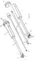
- Fig. 1
- eine perspektivische Darstellung des erfindungsgemäßen Implantates bei der Betätigung durch das erfindungsgemäße Operationsinstrument,
- Fig. 2
- eine perspektivische Darstellung des Implantats isoliert,
- Fig. 3
- eine perspektivische Darstellung des zweiten Implantatteils,
- Fig. 4
- eine perspektivische Darstellung des ersten Implantatteils,
- Fig. 5
- eine perspektivische Darstellung des ersten Implantatteils aus einer gegenüber Fig. 4 anderen Sicht,
- Fig. 6
- eine Seitenansicht des zweiten Implantatteils,
- Fig. 7
- eine Seitenansicht des zweiten Implantatteils mit gegenüber Fig. 6 um 90° gedrehter Darstellung,
- Fig. 8
- einen Querschnitt durch den die Kegelradverzahnung aufweisenden Gewindering,
- Fig. 9
- das in seine Einzelteile zerlegte, erfindungsgemäße Operationsinstrument in einer Draufsicht,
- Fig. 10
- eine perspektivische Darstellung des Operationsinstrumentes komplett montiert und in seine Einzelteile zerlegt,
- Fig. 11
- eine perspektivische Darstellung der Gabel der Hülse und
- Fig. 12
- die Detaildarstellung XII aus Fig. 1.
- Fig. 1
- a perspective view of the implant according to the invention during actuation by the surgical instrument according to the invention,
- Fig. 2
- a perspective view of the implant isolated,
- Fig. 3
- a perspective view of the second implant part,
- Fig. 4
- a perspective view of the first implant part,
- Fig. 5
- 3 shows a perspective view of the first implant part from a different view from FIG. 4,
- Fig. 6
- a side view of the second implant part,
- Fig. 7
- a side view of the second implant part with respect to FIG. 6 rotated by 90 ° representation,
- Fig. 8
- a cross section through the bevel gear having threaded ring,
- Fig. 9
- the decomposed into its parts, inventive surgical instrument in a plan view,
- Fig. 10
- a perspective view of the surgical instrument completely assembled and disassembled into its individual parts,
- Fig. 11
- a perspective view of the fork of the sleeve and
- Fig. 12
- the detailed representation XII of FIG. 1.
Das in der Zeichnung dargestellte Implantat 1 dient zum Einsetzen zwischen in der Zeichnung selber nicht dargestellte Wirbelkörper der Wirbelsäule als Platzhalter für aus der Wirbelsäule entfernte Wirbel oder Wirbelteile. Dieses Implantat 1 weist ein erstes Implantatteil 2 und ein zweites Implantatteil 3 auf, die in Richtung ihrer koaxialen Längsachse gegeneinander verstellbar sind, um im Sinne einer Distraktion der Wirbelkörper eine Längenänderung bewirken zu können. Das erste Implantatteil 2 und das zweite Implantatteil 3 sind als rohrförmige Hülsen gestaltet, wobei das erste Implantatteil 2 das zweite Implantatteil 3 außenseitig umfaßt. Dem ersten Implantatteil 2 ist ein drehbarer Gewindering 4 zugeordnet, der an seiner Innenumfangsfläche ein Ringgewinde 5 aufweist, mit dem dieser in ein dem zweiten Implantatteil 3 zugeordnetes Gewinde 6 eingreift. An der Außenumfangsfläche ist der Gewindering 5 mit einer Kegelradverzahnung 7 versehen (Fig. 8).The implant 1 shown in the drawing is used for insertion between the vertebral body of the spine, not shown in the drawing itself, as a placeholder for vertebrae or vertebrae removed from the vertebral column. This implant 1 has a
Wie insbesondere aus den Figuren 3 und 6 zu erkennen ist, sind im zweiten Implantatteil 3 zwei einander gegenüberliegende Führungsschlitze 8 ausgebildet, in die dem ersten Implantatteil 2 zugeordnete Stifte 9 hineinragen (Fig. 2).As can be seen in particular from FIGS. 3 and 6, two opposing
Neben diesen Stiften 9 weist das erste Implantatteil 2 weiterhin einen Durchbruch 10 auf, der den dem Gewindering 4 zugeordneten Rand 11 schneidet und auf einer Geraden mit einer auf der gegenüberliegenden Seite ausgebildeten Gewindebohrung 12 liegt. Fluchtend sind mit dem Durchbruch 10 in dem zweiten Implantatteil 3 zwei Langlöcher 13 vorgesehen, durch die hindurch die Gewindebohrung 12 in jedweder Höhenlage des zweiten Implantatteils 3 gegenüber dem ersten Implantatteil 1 erreichbar ist.In addition to these pins 9, the
An dem zweiten Implantatteil 3 ist mit Abstand von dessen freien Ende auf der dem ersten Implantatteil 2 abgewandten Seite ein Kranz 14 ausgebildet, in dem parallel zur Längsachse des Implantats 1 verlaufende Löcher 15 ausgebildet sind.At the
Der Gewindering 4 weist am Innenumfang einen Ringbund 16 auf, während das erste Implantatteil 2 eine in der rohrförmigen Hülse ausgebildete, senkrecht zur Längsachse des Implantats 1 verlaufende Quernut 17 aufweist, die parallel zur Verbindungsachse des Durchbruchs 10 und der Gewindebohrung 12 liegt, wobei bei dem in der Zeichnung dargestellten Ausführungsbeispiel die Quernut 17 zweifach beidseits der Verbindungsachse vorgesehen ist.The threaded
Der am Gewindering 4 ausgebildete Ringbund 16 sowie die Quernuten 17 dienen zur besseren Ausrichtung und Bestimmung der Lage eines nachfolgend näher zu beschreibenden Operationsinstrumentes 18, das zur Handhabung und Betätigung des Implantats 1 bei der Längenverstellung dient.The formed on the threaded
Das Operationsinstrument 18 weist dazu an dem freien Ende einer Welle 19 ein zur Wellenachse koaxiales Ritzel 20 auf. An diesem Ritzel 20 ist eine Kegelradverzahnung 21 ausgebildet (Fig. 9, Fig. 10). Die Welle 19 selber ist als Hohlwelle gestaltet, in der ein Stab 22 gegenüber der Hohlwelle verdrehbar gelagert ist. Dieser Stab 22 durchgreift das Ritzel 20 und weist an seinem freien Ende ein zu der Gewindebohrung 12 korrespondierendes Stabgewinde 23 auf. Die Hohlwelle selber ist drehbar in einem Handgriff 24 gelagert, der dazu eine Hülse 25 aufweist, in die die Hohlwelle eingeführt ist. Diese Hülse 25 besitzt an dem dem Ritzel 20 zugeordneten Ende eine Gabel 26 mit vier Gabel fingern 27, von denen zwei zu einem ersten Gabelpaar 28 zusammengefaßt und zwei zu einem zweiten Gabelpaar 29 zusammengefaßt sind.For this purpose, the
Nachdem vorstehend der Aufbau des Implantats 1 und des Operationsinstrumentes 18 geschildert ist, soll nachfolgend deren Zusammenwirken detaillierter dargelegt werden.After the structure of the implant 1 and the
Zum Plazieren des erfindungsgemäßen Implantats 1 als Platzhalter zwischen zwei Wirbelkörpern wird zunächst das Implantat 1 auf die Gabel 26 gesteckt, wobei das zweite Gabelpaar 29 in die beiden Quernuten 17 eingeführt wird und das erste Gabelpaar 28 auf dem Gewindering 4 und radial innen an dem Ringbund 16 zur Anlage kommt, so daß eine axiale Verschiebung des Gewinderinges 4 in der Längsachse des Implantats 1 gegenüber dem ersten Implantatteil 2 blockiert ist. Anschließend wird der Stab 22 mit dem Stabgewinde 23 durch den Durchbruch 10 des ersten Implantatteils 2 sowie die beiden Langlöcher 13 des zweiten Implantatteils 3 geführt und in die Gewindebohrung 12 des ersten Implantatteils 2 eingeschraubt, so daß das Operationsinstrument 18 nicht mehr in radialer Richtung von dem Implantat 1 abgezogen werden kann, die Lage des Operationsinstrumentes 18 damit insgesamt gegenüber dem Implantat 1 gesichert ist, Durch das Einschrauben des Stabgewindes 23 in die Gewindebohrung 12 wird zugleich die Kegelradverzahnung 21 des Ritzels 20 in Eingriff mit der Kegelradverzahnung 7 des Gewinderinges 4 gebracht, so daß bei der nachfolgenden Verdrehung der Welle 19 um ihre Wellenachse durch ein Rändelrad 30 eine Verdrehung des Gewinderinges 4 um die zur Wellenachse um 90° gedrehte Längsachse des Implantats 1 erfolgt.To place the implant 1 according to the invention as a placeholder between two vertebral bodies, the implant 1 is first placed on the
Nach der korrekten Plazierung und Distraktion des Implantats 1 kann das Operationsinstrument 18 in sinngemäßer Umkehrung der vorstehend beschriebenen Schritte wieder von dem Implantat 1 gelöst werden, das durch die dann frei zugänglichen Führungsschlitze 8, Langlöcher 13 und die Gewindebohrungen 12 sowie den Durchbruch 10 genügend Zugangsmöglichkeiten in das innere der hülsenförmigen ersten Implantatteile 2 und zweiten Implantatteile 3 bietet, um Knochenzement oder autologes oder homologes Knochenmaterial in das Implantat einzubringen.After the correct placement and distraction of the implant 1, the
Der in Figur 1 dargestellte mit dem Bezugszeichen 31 bezeichnete Aufsatz dient der Kopplung des Operationsinstruments 18 mit Positionsgebern für die Computer-Navigation.The article designated by the
Claims (21)
Translated fromGermanPriority Applications (1)
| Application Number | Priority Date | Filing Date | Title |
|---|---|---|---|
| DE20122641UDE20122641U1 (en) | 2000-12-27 | 2001-11-14 | Vertebral implant comprises nut with externally accessible array of bevel gear teeth, which is rotatable to cause axial displacement of core relative to sleeve |
Applications Claiming Priority (2)
| Application Number | Priority Date | Filing Date | Title |
|---|---|---|---|
| DE10065232ADE10065232C2 (en) | 2000-12-27 | 2000-12-27 | Implant for insertion between the vertebral body and surgical instrument for handling the implant |
| EP01126995AEP1219266B2 (en) | 2000-12-27 | 2001-11-14 | Implant for the insertion between the vertebraes and operation tool for using the implant |
Related Parent Applications (1)
| Application Number | Title | Priority Date | Filing Date |
|---|---|---|---|
| EP01126995ADivisionEP1219266B2 (en) | 2000-12-27 | 2001-11-14 | Implant for the insertion between the vertebraes and operation tool for using the implant |
Publications (3)
| Publication Number | Publication Date |
|---|---|
| EP1721583A2true EP1721583A2 (en) | 2006-11-15 |
| EP1721583A3 EP1721583A3 (en) | 2007-05-09 |
| EP1721583B1 EP1721583B1 (en) | 2016-04-20 |
Family
ID=7669147
Family Applications (2)
| Application Number | Title | Priority Date | Filing Date |
|---|---|---|---|
| EP06016301.1AExpired - LifetimeEP1721583B1 (en) | 2000-12-27 | 2001-11-14 | Implant for the insertion between the vertebraes and operation tool for using the implant |
| EP01126995AExpired - LifetimeEP1219266B2 (en) | 2000-12-27 | 2001-11-14 | Implant for the insertion between the vertebraes and operation tool for using the implant |
Family Applications After (1)
| Application Number | Title | Priority Date | Filing Date |
|---|---|---|---|
| EP01126995AExpired - LifetimeEP1219266B2 (en) | 2000-12-27 | 2001-11-14 | Implant for the insertion between the vertebraes and operation tool for using the implant |
Country Status (8)
| Country | Link |
|---|---|
| US (1) | US6752832B2 (en) |
| EP (2) | EP1721583B1 (en) |
| JP (1) | JP4060589B2 (en) |
| AT (1) | ATE340543T1 (en) |
| DE (5) | DE10065232C2 (en) |
| DK (2) | DK1219266T3 (en) |
| ES (2) | ES2267652T5 (en) |
| PT (1) | PT1219266E (en) |
Cited By (2)
| Publication number | Priority date | Publication date | Assignee | Title |
|---|---|---|---|---|
| WO2008106912A1 (en) | 2007-03-07 | 2008-09-12 | Ulrich Gmbh & Co. Kg | Intervertebral implant having an elastic component |
| US9211193B2 (en) | 2013-08-30 | 2015-12-15 | Aesculap Implant Systems, Llc | Prosthesis, system and method |
Families Citing this family (363)
| Publication number | Priority date | Publication date | Assignee | Title |
|---|---|---|---|---|
| US20080039859A1 (en)* | 1997-01-02 | 2008-02-14 | Zucherman James F | Spine distraction implant and method |
| US20080027552A1 (en)* | 1997-01-02 | 2008-01-31 | Zucherman James F | Spine distraction implant and method |
| US6159179A (en) | 1999-03-12 | 2000-12-12 | Simonson; Robert E. | Cannula and sizing and insertion method |
| AU4652001A (en)* | 2000-03-31 | 2001-10-08 | Konigsee Implantate Und Instr | Variable-height vertebral implant |
| AU2001280476B2 (en) | 2000-06-30 | 2005-11-24 | Stephen Ritland | Polyaxial connection device and method |
| US7166073B2 (en) | 2000-09-29 | 2007-01-23 | Stephen Ritland | Method and device for microsurgical intermuscular spinal surgery |
| US6692434B2 (en) | 2000-09-29 | 2004-02-17 | Stephen Ritland | Method and device for retractor for microsurgical intermuscular lumbar arthrodesis |
| DE10065232C2 (en) | 2000-12-27 | 2002-11-14 | Ulrich Gmbh & Co Kg | Implant for insertion between the vertebral body and surgical instrument for handling the implant |
| WO2002060330A1 (en)* | 2001-01-29 | 2002-08-08 | Stephen Ritland | Retractor and method for spinal pedicle screw placement |
| US6929606B2 (en)* | 2001-01-29 | 2005-08-16 | Depuy Spine, Inc. | Retractor and method for spinal pedicle screw placement |
| US8940047B2 (en)* | 2001-02-15 | 2015-01-27 | Spinecore, Inc. | Intervertebral spacer device having recessed notch pairs for manipulation using a surgical tool |
| US6673113B2 (en) | 2001-10-18 | 2004-01-06 | Spinecore, Inc. | Intervertebral spacer device having arch shaped spring elements |
| US7169182B2 (en)* | 2001-07-16 | 2007-01-30 | Spinecore, Inc. | Implanting an artificial intervertebral disc |
| US7575576B2 (en) | 2001-07-16 | 2009-08-18 | Spinecore, Inc. | Wedge ramp distractor and related methods for use in implanting artificial intervertebral discs |
| US7235081B2 (en)* | 2001-07-16 | 2007-06-26 | Spinecore, Inc. | Wedge plate inserter/impactor and related methods for use in implanting an artificial intervertebral disc |
| US6989032B2 (en)* | 2001-07-16 | 2006-01-24 | Spinecore, Inc. | Artificial intervertebral disc |
| FR2824261B1 (en) | 2001-05-04 | 2004-05-28 | Ldr Medical | INTERVERTEBRAL DISC PROSTHESIS AND IMPLEMENTATION METHOD AND TOOLS |
| US7635368B2 (en)* | 2001-07-16 | 2009-12-22 | Spinecore, Inc. | Intervertebral spacer device having simultaneously engageable angled perimeters for manipulation using a surgical tool |
| US6554864B2 (en)* | 2001-07-16 | 2003-04-29 | Spinecore, Inc | Surgical method of treating scoliosis |
| US7160327B2 (en) | 2001-07-16 | 2007-01-09 | Spinecore, Inc. | Axially compressible artificial intervertebral disc having limited rotation using a captured ball and socket joint with a solid ball and compression locking post |
| US7695478B2 (en)* | 2001-07-16 | 2010-04-13 | Spinecore, Inc. | Insertion tool for use with intervertebral spacers |
| US7722675B2 (en)* | 2001-07-16 | 2010-05-25 | Spinecore, Inc. | Instruments for reorienting vertebral bones for the treatment of scoliosis |
| US7118599B2 (en) | 2001-07-16 | 2006-10-10 | Spinecore, Inc. | Artificial intervertebral disc |
| US6478801B1 (en)* | 2001-07-16 | 2002-11-12 | Third Millennium Engineering, Llc | Insertion tool for use with tapered trial intervertebral distraction spacers |
| DE60238997D1 (en) | 2001-09-28 | 2011-03-03 | Stephen Ritland | CHROME OR HOOKS |
| US7713302B2 (en) | 2001-10-01 | 2010-05-11 | Spinecore, Inc. | Intervertebral spacer device utilizing a spirally slotted belleville washer having radially spaced concentric grooves |
| US7771477B2 (en) | 2001-10-01 | 2010-08-10 | Spinecore, Inc. | Intervertebral spacer device utilizing a belleville washer having radially spaced concentric grooves |
| US7824410B2 (en) | 2001-10-30 | 2010-11-02 | Depuy Spine, Inc. | Instruments and methods for minimally invasive spine surgery |
| US7008431B2 (en) | 2001-10-30 | 2006-03-07 | Depuy Spine, Inc. | Configured and sized cannula |
| US6916330B2 (en)* | 2001-10-30 | 2005-07-12 | Depuy Spine, Inc. | Non cannulated dilators |
| US6923830B2 (en)* | 2002-02-02 | 2005-08-02 | Gary K. Michelson | Spinal fusion implant having deployable bone engaging projections |
| ATE476930T1 (en) | 2002-02-20 | 2010-08-15 | Stephen Ritland | DEVICE FOR CONNECTING HAND SCREWS |
| DE10210214B4 (en)* | 2002-03-02 | 2005-01-05 | Bernd Schäfer | Distractable spinal implant and tool for distraction |
| US20030187431A1 (en)* | 2002-03-29 | 2003-10-02 | Simonson Robert E. | Apparatus and method for targeting for surgical procedures |
| US6966910B2 (en) | 2002-04-05 | 2005-11-22 | Stephen Ritland | Dynamic fixation device and method of use |
| US8038713B2 (en) | 2002-04-23 | 2011-10-18 | Spinecore, Inc. | Two-component artificial disc replacements |
| US20080027548A9 (en) | 2002-04-12 | 2008-01-31 | Ferree Bret A | Spacerless artificial disc replacements |
| ATE552789T1 (en) | 2002-05-08 | 2012-04-15 | Stephen Ritland | DYNAMIC FIXATION DEVICE |
| AU2003226586A1 (en) | 2002-09-19 | 2004-04-08 | Malan De Villiers | Intervertebral prosthesis |
| US7588573B2 (en)* | 2002-09-23 | 2009-09-15 | Warsaw Orthopedic, Inc. | Expansion tool for adjustable spinal implant |
| EP1558184A2 (en)* | 2002-10-08 | 2005-08-03 | SDGI Holdings, Inc. | Insertion device and techniques for orthopaedic implants |
| JP4654125B2 (en)* | 2002-10-29 | 2011-03-16 | スパインコア,インコーポレイテッド | Instruments, methods, and functions for use in implanting an artificial disc |
| US7909853B2 (en)* | 2004-09-23 | 2011-03-22 | Kyphon Sarl | Interspinous process implant including a binder and method of implantation |
| FR2846550B1 (en) | 2002-11-05 | 2006-01-13 | Ldr Medical | INTERVERTEBRAL DISC PROSTHESIS |
| WO2004052245A1 (en)* | 2002-12-06 | 2004-06-24 | Synthes Ag Chur | Intervertebral implant |
| US7887539B2 (en) | 2003-01-24 | 2011-02-15 | Depuy Spine, Inc. | Spinal rod approximators |
| US7988698B2 (en)* | 2003-01-28 | 2011-08-02 | Depuy Spine, Inc. | Spinal rod approximator |
| EP1596738A4 (en) | 2003-02-25 | 2010-01-20 | Stephen Ritland | Adjustable rod and connector device and method of use |
| US6908484B2 (en) | 2003-03-06 | 2005-06-21 | Spinecore, Inc. | Cervical disc replacement |
| DE10311477A1 (en)* | 2003-03-15 | 2004-09-23 | Ulrich Gmbh & Co. Kg | Implant to be inserted between the vertebral body of the spine |
| US20040186569A1 (en)* | 2003-03-20 | 2004-09-23 | Berry Bret M. | Height adjustable vertebral body and disc space replacement devices |
| WO2004084742A1 (en) | 2003-03-24 | 2004-10-07 | Theken Surgical Llc | Spinal implant adjustment device |
| CA2524066C (en)* | 2003-04-28 | 2011-03-15 | Michael Guetlin | Intervertebral implant |
| DE202004021289U1 (en)† | 2003-05-14 | 2007-06-06 | Kraus, Kilian | Height-adjustable implant for insertion between vertebral bodies and handling tool |
| DE10324108B3 (en)* | 2003-05-21 | 2005-01-27 | Aesculap Ag & Co. Kg | Backbone implant is inserted with contracted contact disc which is expanded to optimum area following insertion |
| WO2004110247A2 (en) | 2003-05-22 | 2004-12-23 | Stephen Ritland | Intermuscular guide for retractor insertion and method of use |
| US7442211B2 (en) | 2003-05-27 | 2008-10-28 | Spinalmotion, Inc. | Intervertebral prosthetic disc |
| DE10324319A1 (en)* | 2003-05-27 | 2004-12-16 | Ulrich Gmbh & Co. Kg | Implant and instrument for placement and distraction of the implant |
| WO2004105656A1 (en)* | 2003-05-27 | 2004-12-09 | Pentax Corporation | Surgical instrument |
| US7156849B2 (en)* | 2003-06-16 | 2007-01-02 | Depuy Spine, Inc. | Rod reduction nut and driver tool |
| DE10328307A1 (en)* | 2003-06-23 | 2005-02-03 | Franz Rennebaum | Vertebral prosthesis |
| DE50307429D1 (en)* | 2003-08-04 | 2007-07-19 | Cervitech Inc | Cervical prosthesis with insertion instrument |
| US7458988B2 (en)* | 2003-11-05 | 2008-12-02 | Warsaw Orthopedic, Inc. | Compressible corpectomy device |
| DE10357926B3 (en)* | 2003-12-11 | 2005-09-01 | Deltacor Gmbh | Length adjustable spinal implant |
| ATE441376T1 (en)* | 2003-12-17 | 2009-09-15 | Depuy Spine Inc | INSTRUMENTS AND PROCEDURES FOR BONE ANCHOR PROCEDURES AND SPINAL BAR REDUCTION |
| US7842044B2 (en)* | 2003-12-17 | 2010-11-30 | Depuy Spine, Inc. | Instruments and methods for bone anchor engagement and spinal rod reduction |
| US7625379B2 (en) | 2004-01-26 | 2009-12-01 | Warsaw Orthopedic, Inc. | Methods and instrumentation for inserting intervertebral grafts and devices |
| EP2113227B1 (en) | 2004-02-04 | 2015-07-29 | LDR Medical | Intervertebral disc prosthesis |
| FR2865629B1 (en) | 2004-02-04 | 2007-01-26 | Ldr Medical | INTERVERTEBRAL DISC PROSTHESIS |
| US7468076B2 (en)* | 2004-02-20 | 2008-12-23 | Spinecore, Inc. | Artificial intervertebral disc having a universal joint |
| US7393361B2 (en)* | 2004-02-20 | 2008-07-01 | Spinecore, Inc. | Artificial intervertebral disc having a bored semispherical bearing with a compression locking post and retaining caps |
| FR2869528B1 (en) | 2004-04-28 | 2007-02-02 | Ldr Medical | INTERVERTEBRAL DISC PROSTHESIS |
| US7544208B1 (en)* | 2004-05-03 | 2009-06-09 | Theken Spine, Llc | Adjustable corpectomy apparatus |
| JP2006000699A (en)* | 2004-06-15 | 2006-01-05 | Canon Inc | Gas treatment method and apparatus |
| US7909843B2 (en) | 2004-06-30 | 2011-03-22 | Thompson Surgical Instruments, Inc. | Elongateable surgical port and dilator |
| US7585326B2 (en) | 2004-08-06 | 2009-09-08 | Spinalmotion, Inc. | Methods and apparatus for intervertebral disc prosthesis insertion |
| US7776045B2 (en)* | 2004-08-20 | 2010-08-17 | Warsaw Orthopedic, Inc. | Instrumentation and methods for vertebral distraction |
| US7455639B2 (en) | 2004-09-20 | 2008-11-25 | Stephen Ritland | Opposing parallel bladed retractor and method of use |
| WO2006058221A2 (en) | 2004-11-24 | 2006-06-01 | Abdou Samy M | Devices and methods for inter-vertebral orthopedic device placement |
| US7736380B2 (en) | 2004-12-21 | 2010-06-15 | Rhausler, Inc. | Cervical plate system |
| FR2879436B1 (en) | 2004-12-22 | 2007-03-09 | Ldr Medical | INTERVERTEBRAL DISC PROSTHESIS |
| US8083797B2 (en) | 2005-02-04 | 2011-12-27 | Spinalmotion, Inc. | Intervertebral prosthetic disc with shock absorption |
| US7993342B2 (en) | 2005-02-17 | 2011-08-09 | Kyphon Sarl | Percutaneous spinal implants and methods |
| US8092459B2 (en)* | 2005-02-17 | 2012-01-10 | Kyphon Sarl | Percutaneous spinal implants and methods |
| US20070276373A1 (en)* | 2005-02-17 | 2007-11-29 | Malandain Hugues F | Percutaneous Spinal Implants and Methods |
| US8034080B2 (en)* | 2005-02-17 | 2011-10-11 | Kyphon Sarl | Percutaneous spinal implants and methods |
| US7998208B2 (en)* | 2005-02-17 | 2011-08-16 | Kyphon Sarl | Percutaneous spinal implants and methods |
| US8029567B2 (en) | 2005-02-17 | 2011-10-04 | Kyphon Sarl | Percutaneous spinal implants and methods |
| US8096994B2 (en) | 2005-02-17 | 2012-01-17 | Kyphon Sarl | Percutaneous spinal implants and methods |
| US20060184248A1 (en)* | 2005-02-17 | 2006-08-17 | Edidin Avram A | Percutaneous spinal implants and methods |
| US7927354B2 (en)* | 2005-02-17 | 2011-04-19 | Kyphon Sarl | Percutaneous spinal implants and methods |
| US8096995B2 (en) | 2005-02-17 | 2012-01-17 | Kyphon Sarl | Percutaneous spinal implants and methods |
| US7951175B2 (en) | 2005-03-04 | 2011-05-31 | Depuy Spine, Inc. | Instruments and methods for manipulating a vertebra |
| US7951172B2 (en) | 2005-03-04 | 2011-05-31 | Depuy Spine Sarl | Constrained motion bone screw assembly |
| JP2006253316A (en)* | 2005-03-09 | 2006-09-21 | Sony Corp | Solid-state imaging device |
| US7942903B2 (en) | 2005-04-12 | 2011-05-17 | Moskowitz Ahmnon D | Bi-directional fixating transvertebral body screws and posterior cervical and lumbar interarticulating joint calibrated stapling devices for spinal fusion |
| US11903849B2 (en) | 2005-04-12 | 2024-02-20 | Moskowitz Family Llc | Intervertebral implant and tool assembly |
| US7704279B2 (en) | 2005-04-12 | 2010-04-27 | Moskowitz Mosheh T | Bi-directional fixating transvertebral body screws, zero-profile horizontal intervertebral miniplates, expansile intervertebral body fusion devices, and posterior motion-calibrating interarticulating joint stapling device for spinal fusion |
| US7575580B2 (en)* | 2005-04-15 | 2009-08-18 | Warsaw Orthopedic, Inc. | Instruments, implants and methods for positioning implants into a spinal disc space |
| US7674296B2 (en) | 2005-04-21 | 2010-03-09 | Globus Medical, Inc. | Expandable vertebral prosthesis |
| US7811327B2 (en) | 2005-04-21 | 2010-10-12 | Globus Medical Inc. | Expandable vertebral prosthesis |
| US8308802B2 (en) | 2010-01-21 | 2012-11-13 | Globus Medical, Inc. | Expandable vertebral prosthesis |
| US8777959B2 (en) | 2005-05-27 | 2014-07-15 | Spinecore, Inc. | Intervertebral disc and insertion methods therefor |
| US20060293692A1 (en) | 2005-06-02 | 2006-12-28 | Whipple Dale E | Instruments and methods for manipulating a spinal fixation element |
| FR2887762B1 (en) | 2005-06-29 | 2007-10-12 | Ldr Medical Soc Par Actions Si | INTERVERTEBRAL DISC PROSTHESIS INSERTION INSTRUMENTATION BETWEEN VERTEBRATES |
| JP4988735B2 (en) | 2005-07-19 | 2012-08-01 | リットランド、ステファン | Rod extension for elongating fusion structures |
| FR2891135B1 (en) | 2005-09-23 | 2008-09-12 | Ldr Medical Sarl | INTERVERTEBRAL DISC PROSTHESIS |
| US9028550B2 (en)* | 2005-09-26 | 2015-05-12 | Coalign Innovations, Inc. | Selectively expanding spine cage with enhanced bone graft infusion |
| WO2007062080A2 (en)* | 2005-11-21 | 2007-05-31 | Philipp Lang | Intervetebral devices and methods |
| FR2893838B1 (en) | 2005-11-30 | 2008-08-08 | Ldr Medical Soc Par Actions Si | PROSTHESIS OF INTERVERTEBRAL DISC AND INSTRUMENTATION OF INSERTION OF THE PROSTHESIS BETWEEN VERTEBRATES |
| CA2636145C (en) | 2006-01-19 | 2014-04-22 | N.V. Organon | Kit for and method of assembling an applicator for inserting an implant |
| US8066714B2 (en) | 2006-03-17 | 2011-11-29 | Warsaw Orthopedic Inc. | Instrumentation for distraction and insertion of implants in a spinal disc space |
| US7985246B2 (en)* | 2006-03-31 | 2011-07-26 | Warsaw Orthopedic, Inc. | Methods and instruments for delivering interspinous process spacers |
| WO2007121320A2 (en) | 2006-04-12 | 2007-10-25 | Spinalmotion, Inc. | Posterior spinal device and method |
| US20070270960A1 (en)* | 2006-04-24 | 2007-11-22 | Sdgi Holdings, Inc. | Extendable anchor in a vertebral implant and methods of use |
| US8657882B2 (en)* | 2006-04-24 | 2014-02-25 | Warsaw Orthopedic, Inc. | Expandable intervertebral devices and methods of use |
| US7981157B2 (en) | 2006-04-27 | 2011-07-19 | Warsaw Orthopedic, Inc. | Self-contained expandable implant and method |
| US8187331B2 (en)* | 2006-04-27 | 2012-05-29 | Warsaw Orthopedic, Inc. | Expandable vertebral implant and methods of use |
| US7758648B2 (en) | 2006-04-27 | 2010-07-20 | Warsaw Orthopedic, Inc. | Stabilized, adjustable expandable implant and method |
| US7914581B2 (en) | 2006-04-27 | 2011-03-29 | Warsaw Orthopedic, Inc. | Expandable implant, instrument, and method |
| US7575601B2 (en)* | 2006-04-27 | 2009-08-18 | Warsaw Orthopedic, Inc. | Locking expandable implant and method |
| US7879096B2 (en)* | 2006-04-27 | 2011-02-01 | Warsaw Orthopedic, Inc. | Centrally driven expandable implant |
| US7794501B2 (en)* | 2006-04-27 | 2010-09-14 | Wasaw Orthopedic, Inc. | Expandable intervertebral spacers and methods of use |
| US7708779B2 (en) | 2006-05-01 | 2010-05-04 | Warsaw Orthopedic, Inc. | Expandable intervertebral spacers and methods of use |
| US8303601B2 (en) | 2006-06-07 | 2012-11-06 | Stryker Spine | Collet-activated distraction wedge inserter |
| US7959564B2 (en)* | 2006-07-08 | 2011-06-14 | Stephen Ritland | Pedicle seeker and retractor, and methods of use |
| ES2395298T3 (en)* | 2006-07-14 | 2013-02-11 | Biedermann Technologies Gmbh & Co. Kg | Separator for insertion between two vertebrae |
| WO2008033457A2 (en)* | 2006-09-14 | 2008-03-20 | The University Of Toledo | Variable height vertebral body replacement implant |
| US7815683B2 (en)* | 2006-10-16 | 2010-10-19 | Warsaw Orthopedic, Inc. | Implants with helical supports and methods of use for spacing vertebral members |
| US20080177298A1 (en)* | 2006-10-24 | 2008-07-24 | St. Francis Medical Technologies, Inc. | Tensioner Tool and Method for Implanting an Interspinous Process Implant Including a Binder |
| US20080140204A1 (en)* | 2006-12-07 | 2008-06-12 | Warsaw Orthopedic, Inc. | Vertebral Implant Systems and Methods of Use |
| US7955392B2 (en) | 2006-12-14 | 2011-06-07 | Warsaw Orthopedic, Inc. | Interspinous process devices and methods |
| US8465546B2 (en) | 2007-02-16 | 2013-06-18 | Ldr Medical | Intervertebral disc prosthesis insertion assemblies |
| KR101453961B1 (en) | 2007-03-13 | 2014-10-21 | 신세스 게엠바하 | adjustable intervertebral implant |
| US9237954B2 (en)* | 2007-03-29 | 2016-01-19 | Life Spine, Inc. | Height adjustable spinal prostheses |
| US8172847B2 (en)* | 2007-03-29 | 2012-05-08 | Depuy Spine, Inc. | In-line rod reduction device and methods |
| US8454622B2 (en)* | 2007-04-25 | 2013-06-04 | Spinal Elements, Inc. | Spinal implant distractor/inserter |
| US8062304B2 (en)* | 2007-04-25 | 2011-11-22 | Spinal Elements, Inc. | Spinal implant distractor/inserter |
| FI122996B (en)* | 2007-05-10 | 2012-09-28 | Teliasonera Ab | Processing of service request |
| FR2916956B1 (en) | 2007-06-08 | 2012-12-14 | Ldr Medical | INTERSOMATIC CAGE, INTERVERTEBRAL PROSTHESIS, ANCHORING DEVICE AND IMPLANTATION INSTRUMENTATION |
| US7887541B2 (en)* | 2007-07-26 | 2011-02-15 | Depuy Spine, Inc. | Spinal rod reduction instruments and methods for use |
| US20090043391A1 (en) | 2007-08-09 | 2009-02-12 | Spinalmotion, Inc. | Customized Intervertebral Prosthetic Disc with Shock Absorption |
| US8328818B1 (en) | 2007-08-31 | 2012-12-11 | Globus Medical, Inc. | Devices and methods for treating bone |
| US8790348B2 (en) | 2007-09-28 | 2014-07-29 | Depuy Spine, Inc. | Dual pivot instrument for reduction of a fixation element and method of use |
| US20090105834A1 (en) | 2007-10-22 | 2009-04-23 | Spinalmotion, Inc. | Dynamic Spacer Device and Method for Spanning a Space Formed upon Removal of an Intervertebral Disc |
| US8142441B2 (en) | 2008-10-16 | 2012-03-27 | Aesculap Implant Systems, Llc | Surgical instrument and method of use for inserting an implant between two bones |
| DE102007052042A1 (en)* | 2007-10-30 | 2009-05-14 | Kilian Kraus | Height-adjustable spine implant |
| US8591587B2 (en) | 2007-10-30 | 2013-11-26 | Aesculap Implant Systems, Llc | Vertebral body replacement device and method for use to maintain a space between two vertebral bodies within a spine |
| US20090112325A1 (en)* | 2007-10-30 | 2009-04-30 | Biospine, Llc | Footplate member and a method for use in a vertebral body replacement device |
| US8182537B2 (en) | 2007-10-30 | 2012-05-22 | Aesculap Implant Systems, Llc | Vertebral body replacement device and method for use to maintain a space between two vertebral bodies within a spine |
| DE102007052173B4 (en) | 2007-10-30 | 2012-01-12 | Kilian Kraus | Handling tool for a medical implant |
| US8241363B2 (en) | 2007-12-19 | 2012-08-14 | Depuy Spine, Inc. | Expandable corpectomy spinal fusion cage |
| US8241294B2 (en)* | 2007-12-19 | 2012-08-14 | Depuy Spine, Inc. | Instruments for expandable corpectomy spinal fusion cage |
| US20090198241A1 (en)* | 2008-02-04 | 2009-08-06 | Phan Christopher U | Spine distraction tools and methods of use |
| US8323345B2 (en)* | 2008-02-14 | 2012-12-04 | U.S. Spine, Inc. | Anterior lumbar interbody fusion cage device and associated method |
| US8709015B2 (en) | 2008-03-10 | 2014-04-29 | DePuy Synthes Products, LLC | Bilateral vertebral body derotation system |
| US8608746B2 (en) | 2008-03-10 | 2013-12-17 | DePuy Synthes Products, LLC | Derotation instrument with reduction functionality |
| US8864770B2 (en)* | 2008-03-12 | 2014-10-21 | Spinal Elements, Inc. | Offset opposing arm spinal implant distractor/inserter |
| EP2271289A4 (en)* | 2008-03-28 | 2013-01-09 | K2M Inc | Expandable cage with locking device |
| WO2009151734A1 (en)* | 2008-03-28 | 2009-12-17 | K2M, Inc. | Expandable cage |
| EP2278941A1 (en) | 2008-05-05 | 2011-02-02 | Spinalmotion Inc. | Polyaryletherketone artificial intervertebral disc |
| US10973556B2 (en) | 2008-06-17 | 2021-04-13 | DePuy Synthes Products, Inc. | Adjustable implant assembly |
| BRPI0822953A2 (en) | 2008-09-04 | 2015-06-23 | Synthes Gmbh | Adjustable intervertebral implant |
| US8114088B2 (en) | 2008-09-19 | 2012-02-14 | Zimmer Spine, Inc. | Geared spinal implant inserter-distractor |
| US8545566B2 (en)* | 2008-10-13 | 2013-10-01 | Globus Medical, Inc. | Articulating spacer |
| US8128701B2 (en) | 2008-10-24 | 2012-03-06 | Ulrich Gmbh & Co. Kg | Implant for use between spiral vertebrae |
| US8114131B2 (en) | 2008-11-05 | 2012-02-14 | Kyphon Sarl | Extension limiting devices and methods of use for the spine |
| US10045860B2 (en) | 2008-12-19 | 2018-08-14 | Amicus Design Group, Llc | Interbody vertebral prosthetic device with self-deploying screws |
| US8523944B2 (en) | 2008-12-31 | 2013-09-03 | Spinex Tec, Llc | Methods and apparatus for vertebral body distraction and fusion employing flexure members |
| US8721723B2 (en) | 2009-01-12 | 2014-05-13 | Globus Medical, Inc. | Expandable vertebral prosthesis |
| US8142435B2 (en)* | 2009-02-19 | 2012-03-27 | Aesculap Implant Systems, Llc | Multi-functional surgical instrument and method of use for inserting an implant between two bones |
| US9687357B2 (en) | 2009-03-12 | 2017-06-27 | Nuvasive, Inc. | Vertebral body replacement |
| US9387090B2 (en) | 2009-03-12 | 2016-07-12 | Nuvasive, Inc. | Vertebral body replacement |
| US8628577B1 (en) | 2009-03-19 | 2014-01-14 | Ex Technology, Llc | Stable device for intervertebral distraction and fusion |
| US8292963B2 (en) | 2009-04-23 | 2012-10-23 | Warsaw Orthopedic, Inc. | Expandable implant for supporting skeletal structures |
| US8876905B2 (en)* | 2009-04-29 | 2014-11-04 | DePuy Synthes Products, LLC | Minimally invasive corpectomy cage and instrument |
| US8206394B2 (en) | 2009-05-13 | 2012-06-26 | Depuy Spine, Inc. | Torque limited instrument for manipulating a spinal rod relative to a bone anchor |
| WO2011011626A2 (en)* | 2009-07-22 | 2011-01-27 | Spinex Tec, Llc | Coaxial screw gear sleeve mechanism |
| US9668882B2 (en)* | 2009-10-02 | 2017-06-06 | Amedica Corporation | Biomedical implant inserters and related apparatus, systems, and methods |
| US9155628B2 (en) | 2009-10-15 | 2015-10-13 | Globus Medical, Inc. | Expandable fusion device and method of installation thereof |
| US8062375B2 (en) | 2009-10-15 | 2011-11-22 | Globus Medical, Inc. | Expandable fusion device and method of installation thereof |
| US11564807B2 (en) | 2009-10-15 | 2023-01-31 | Globus Medical, Inc. | Expandable fusion device and method of installation thereof |
| US10098758B2 (en) | 2009-10-15 | 2018-10-16 | Globus Medical, Inc. | Expandable fusion device and method of installation thereof |
| US8556979B2 (en) | 2009-10-15 | 2013-10-15 | Globus Medical, Inc. | Expandable fusion device and method of installation thereof |
| US8685098B2 (en) | 2010-06-25 | 2014-04-01 | Globus Medical, Inc. | Expandable fusion device and method of installation thereof |
| US8709086B2 (en) | 2009-10-15 | 2014-04-29 | Globus Medical, Inc. | Expandable fusion device and method of installation thereof |
| US8679183B2 (en) | 2010-06-25 | 2014-03-25 | Globus Medical | Expandable fusion device and method of installation thereof |
| US10806596B2 (en) | 2009-10-15 | 2020-10-20 | Globus Medical, Inc. | Expandable fusion device and method installation thereof |
| US9216095B2 (en) | 2009-10-15 | 2015-12-22 | Globus Medical, Inc. | Expandable fusion device and method of installation thereof |
| US10327917B2 (en) | 2009-10-15 | 2019-06-25 | Globus Medical, Inc. | Expandable fusion device and method of installation thereof |
| US11344430B2 (en) | 2009-10-15 | 2022-05-31 | Globus Medical, Inc. | Expandable fusion device and method of installation thereof |
| US11103366B2 (en) | 2009-10-15 | 2021-08-31 | Globus Medical, Inc. | Expandable fusion device and method of installation thereof |
| WO2011059498A1 (en) | 2009-11-11 | 2011-05-19 | Nuvasive, Inc. | Surgical access system and related methods |
| US8764806B2 (en) | 2009-12-07 | 2014-07-01 | Samy Abdou | Devices and methods for minimally invasive spinal stabilization and instrumentation |
| US8636746B2 (en)* | 2009-12-31 | 2014-01-28 | Spinex Tec, Llc | Methods and apparatus for insertion of vertebral body distraction and fusion devices |
| US8353963B2 (en) | 2010-01-12 | 2013-01-15 | Globus Medical | Expandable spacer and method for use thereof |
| US9913726B2 (en) | 2010-02-24 | 2018-03-13 | Globus Medical, Inc. | Expandable intervertebral spacer and method of posterior insertion thereof |
| US8147526B2 (en) | 2010-02-26 | 2012-04-03 | Kyphon Sarl | Interspinous process spacer diagnostic parallel balloon catheter and methods of use |
| US9271842B2 (en)* | 2010-04-12 | 2016-03-01 | Globus Medical, Inc. | Expandable trial assembly for expandable vertebral implant |
| US8870880B2 (en) | 2010-04-12 | 2014-10-28 | Globus Medical, Inc. | Angling inserter tool for expandable vertebral implant |
| US9301850B2 (en) | 2010-04-12 | 2016-04-05 | Globus Medical, Inc. | Expandable vertebral implant |
| US9579211B2 (en)* | 2010-04-12 | 2017-02-28 | Globus Medical, Inc. | Expandable vertebral implant |
| US8282683B2 (en) | 2010-04-12 | 2012-10-09 | Globus Medical, Inc. | Expandable vertebral implant |
| US8591585B2 (en) | 2010-04-12 | 2013-11-26 | Globus Medical, Inc. | Expandable vertebral implant |
| DE102010018379B4 (en) | 2010-04-26 | 2018-10-18 | Peter Metz-Stavenhagen | Spine implant and tool for this |
| US9597200B2 (en) | 2010-06-25 | 2017-03-21 | Globus Medical, Inc | Expandable fusion device and method of installation thereof |
| US9066814B2 (en) | 2010-08-02 | 2015-06-30 | Ulrich Medical Usa, Inc. | Implant assembly having an angled head |
| US9351848B2 (en) | 2010-09-03 | 2016-05-31 | Globus Medical, Inc. | Expandable fusion device and method of installation thereof |
| US8845731B2 (en) | 2010-09-03 | 2014-09-30 | Globus Medical, Inc. | Expandable fusion device and method of installation thereof |
| US9855151B2 (en) | 2010-09-03 | 2018-01-02 | Globus Medical, Inc | Expandable fusion device and method of installation thereof |
| US9474625B2 (en) | 2010-09-03 | 2016-10-25 | Globus Medical, Inc | Expandable fusion device and method of installation thereof |
| US12059358B2 (en) | 2010-09-03 | 2024-08-13 | Globus Medical Inc. | Expandable fusion device and method of installation thereof |
| US10842644B2 (en) | 2010-09-03 | 2020-11-24 | Globus Medical, Inc. | Expandable fusion device and method of installation thereof |
| US8852279B2 (en) | 2010-09-03 | 2014-10-07 | Globus Medical, Inc. | Expandable fusion device and method of installation thereof |
| US12370057B2 (en) | 2010-09-03 | 2025-07-29 | Globus Medical, Inc. | Expandable fusion device and method of installation thereof |
| US10085849B2 (en) | 2010-09-03 | 2018-10-02 | Globus Medical, Inc. | Expandable fusion device and method of installation thereof |
| US8491659B2 (en) | 2010-09-03 | 2013-07-23 | Globus Medical, Inc. | Expandable fusion device and method of installation thereof |
| US9566168B2 (en) | 2010-09-03 | 2017-02-14 | Globus Medical, Inc. | Expandable fusion device and method of installation thereof |
| US8845732B2 (en) | 2010-09-03 | 2014-09-30 | Globus Medical, Inc. | Expandable fusion device and method of installation thereof |
| US8632595B2 (en) | 2010-09-03 | 2014-01-21 | Globus Medical, Inc. | Expandable fusion device and method of installation thereof |
| US10779957B2 (en) | 2010-09-03 | 2020-09-22 | Globus Medical, Inc. | Expandable fusion device and method of installation thereof |
| US8435298B2 (en) | 2010-09-03 | 2013-05-07 | Globus Medical, Inc. | Expandable fusion device and method of installation thereof |
| US10869768B2 (en) | 2010-09-03 | 2020-12-22 | Globus Medical Inc. | Expandable fusion device and method of installation thereof |
| US10835387B2 (en) | 2010-09-03 | 2020-11-17 | Globus Medical Inc. | Expandable fusion device and method of installation thereof |
| US10945858B2 (en) | 2010-09-03 | 2021-03-16 | Globus Medical, Inc. | Expandable interspinous process fixation device |
| US8845734B2 (en) | 2010-09-03 | 2014-09-30 | Globus Medical, Inc. | Expandable fusion device and method of installation thereof |
| US10512550B2 (en) | 2010-09-03 | 2019-12-24 | Globus Medical, Inc. | Expandable interspinous process fixation device |
| US10758367B2 (en) | 2010-09-03 | 2020-09-01 | Globus Medical Inc. | Expandable fusion device and method of installation thereof |
| US10709573B2 (en) | 2010-09-03 | 2020-07-14 | Globus Medical Inc. | Expandable fusion device and method of installation thereof |
| US9907673B2 (en) | 2010-09-03 | 2018-03-06 | Globus Medical, Inc. | Expandable fusion device and method of installation thereof |
| US11793654B2 (en) | 2010-09-03 | 2023-10-24 | Globus Medical, Inc. | Expandable fusion device and method of installation thereof |
| US11446162B2 (en) | 2010-09-03 | 2022-09-20 | Globus Medical, Inc. | Expandable fusion device and method of installation thereof |
| US8876866B2 (en) | 2010-12-13 | 2014-11-04 | Globus Medical, Inc. | Spinous process fusion devices and methods thereof |
| US20120179258A1 (en)* | 2010-12-28 | 2012-07-12 | Paul Glazer | Spinal spacer devices, tools, and methods |
| US8377140B2 (en) | 2011-01-12 | 2013-02-19 | Ebi, Llc | Expandable spinal implant device |
| US8740980B2 (en) | 2011-01-27 | 2014-06-03 | Warsaw Orthopedic, Inc. | Expandable medical implant |
| DE102011002076A1 (en)* | 2011-04-15 | 2012-10-18 | Z.-Medical Gmbh & Co. Kg | Intervertebral implant and device for insertion |
| DE102011018695B4 (en) | 2011-04-26 | 2022-08-25 | Peter Metz-Stavenhagen | Spinal implant and tool therefor |
| DE102011018692B4 (en) | 2011-04-26 | 2016-06-23 | Peter Metz-Stavenhagen | Spinal implant, tool and method of distraction of the spinal implant |
| DE102011018694B4 (en) | 2011-04-26 | 2022-08-25 | Peter Metz-Stavenhagen | Spinal implant and tool therefor |
| US8845728B1 (en) | 2011-09-23 | 2014-09-30 | Samy Abdou | Spinal fixation devices and methods of use |
| US8864833B2 (en) | 2011-09-30 | 2014-10-21 | Globus Medical, Inc. | Expandable fusion device and method of installation thereof |
| US20130226240A1 (en) | 2012-02-22 | 2013-08-29 | Samy Abdou | Spinous process fixation devices and methods of use |
| ES2770824T3 (en) | 2012-03-19 | 2020-07-03 | Amicus Design Group Llc | Intervertebral fusion prosthetic and orthopedic device with self-deploying anchors |
| US9566165B2 (en) | 2012-03-19 | 2017-02-14 | Amicus Design Group, Llc | Interbody vertebral prosthetic and orthopedic fusion device with self-deploying anchors |
| US8771277B2 (en) | 2012-05-08 | 2014-07-08 | Globus Medical, Inc | Device and a method for implanting a spinous process fixation device |
| US9044342B2 (en) | 2012-05-30 | 2015-06-02 | Globus Medical, Inc. | Expandable interbody spacer |
| US9173695B2 (en)* | 2012-07-24 | 2015-11-03 | Paradigm Spine, Llc | Bone fastener assembly instrument |
| US9198767B2 (en) | 2012-08-28 | 2015-12-01 | Samy Abdou | Devices and methods for spinal stabilization and instrumentation |
| US9320617B2 (en) | 2012-10-22 | 2016-04-26 | Cogent Spine, LLC | Devices and methods for spinal stabilization and instrumentation |
| US10299934B2 (en) | 2012-12-11 | 2019-05-28 | Globus Medical, Inc | Expandable vertebral implant |
| US10350081B2 (en) | 2012-12-11 | 2019-07-16 | Globus Medical, Inc. | Expandable vertebral implant |
| US9011493B2 (en) | 2012-12-31 | 2015-04-21 | Globus Medical, Inc. | Spinous process fixation system and methods thereof |
| US9198697B2 (en) | 2013-03-13 | 2015-12-01 | Globus Medical, Inc. | Spinous process fixation system and methods thereof |
| US9486251B2 (en) | 2012-12-31 | 2016-11-08 | Globus Medical, Inc. | Spinous process fixation system and methods thereof |
| US9585765B2 (en) | 2013-02-14 | 2017-03-07 | Globus Medical, Inc | Devices and methods for correcting vertebral misalignment |
| US9402738B2 (en) | 2013-02-14 | 2016-08-02 | Globus Medical, Inc. | Devices and methods for correcting vertebral misalignment |
| US10105239B2 (en) | 2013-02-14 | 2018-10-23 | Globus Medical, Inc. | Devices and methods for correcting vertebral misalignment |
| US9782265B2 (en) | 2013-02-15 | 2017-10-10 | Globus Medical, Inc | Articulating and expandable vertebral implant |
| US10117754B2 (en) | 2013-02-25 | 2018-11-06 | Globus Medical, Inc. | Expandable intervertebral implant |
| US9554918B2 (en) | 2013-03-01 | 2017-01-31 | Globus Medical, Inc. | Articulating expandable intervertebral implant |
| US9204972B2 (en) | 2013-03-01 | 2015-12-08 | Globus Medical, Inc. | Articulating expandable intervertebral implant |
| US9770343B2 (en) | 2013-03-01 | 2017-09-26 | Globus Medical Inc. | Articulating expandable intervertebral implant |
| US9198772B2 (en) | 2013-03-01 | 2015-12-01 | Globus Medical, Inc. | Articulating expandable intervertebral implant |
| US10004607B2 (en) | 2013-03-01 | 2018-06-26 | Globus Medical, Inc. | Articulating expandable intervertebral implant |
| US12193948B2 (en) | 2013-03-13 | 2025-01-14 | Life Spine, Inc. | Expandable implant assembly |
| US10426632B2 (en) | 2013-03-13 | 2019-10-01 | Life Spine, Inc. | Expandable spinal interbody assembly |
| CA2845613C (en)* | 2013-03-13 | 2018-04-24 | Coalign Innovations, Inc. | Selectively expanding spine cage with enhanced bone graft infusion |
| US10292832B2 (en) | 2013-03-14 | 2019-05-21 | Ohio State Innovation Foundation | Spinal fixation device |
| US9707096B2 (en) | 2013-03-14 | 2017-07-18 | K2M, Inc. | Spinal fixation device |
| US9572677B2 (en) | 2013-03-15 | 2017-02-21 | Globus Medical, Inc. | Expandable intervertebral implant |
| US9149367B2 (en) | 2013-03-15 | 2015-10-06 | Globus Medical Inc | Expandable intervertebral implant |
| US9186258B2 (en) | 2013-03-15 | 2015-11-17 | Globus Medical, Inc. | Expandable intervertebral implant |
| US9968460B2 (en) | 2013-03-15 | 2018-05-15 | Medsmart Innovation Inc. | Dynamic spinal segment replacement |
| US9034045B2 (en) | 2013-03-15 | 2015-05-19 | Globus Medical, Inc | Expandable intervertebral implant |
| US9456906B2 (en) | 2013-03-15 | 2016-10-04 | Globus Medical, Inc. | Expandable intervertebral implant |
| US9233009B2 (en) | 2013-03-15 | 2016-01-12 | Globus Medical, Inc. | Expandable intervertebral implant |
| US9808354B2 (en) | 2014-01-17 | 2017-11-07 | Stryker European Holdings I, Llc | Implant insertion tool |
| US9662224B2 (en) | 2014-02-07 | 2017-05-30 | Globus Medical, Inc. | Variable lordosis spacer and related methods of use |
| US9839528B2 (en) | 2014-02-07 | 2017-12-12 | Globus Medical, Inc. | Variable lordosis spacer and related methods of use |
| US9402739B2 (en) | 2014-02-07 | 2016-08-02 | Globus Medical, Inc. | Variable lordosis spacer and related methods of use |
| US9486328B2 (en) | 2014-04-01 | 2016-11-08 | Ex Technology, Llc | Expandable intervertebral cage |
| US8940049B1 (en) | 2014-04-01 | 2015-01-27 | Ex Technology, Llc | Expandable intervertebral cage |
| US9901459B2 (en) | 2014-12-16 | 2018-02-27 | Globus Medical, Inc. | Expandable fusion devices and methods of installation thereof |
| US9775719B2 (en) | 2015-03-23 | 2017-10-03 | Musc Foundation For Research Development | Expandable vertebral body replacement device and method |
| US9814602B2 (en) | 2015-05-14 | 2017-11-14 | Globus Medical, Inc. | Expandable intervertebral implants and methods of installation thereof |
| US10765532B2 (en) | 2015-05-21 | 2020-09-08 | Globus Medical, Inc. | Device and method for deployment of an anchoring device for intervertebral spinal fusion |
| US10631997B2 (en) | 2015-05-21 | 2020-04-28 | Globus Medical, Inc. | Device and method for deployment of an anchoring device for intervertebral spinal fusion |
| US10433975B2 (en) | 2015-05-21 | 2019-10-08 | Globus Medical, Inc. | Device and method for deployment of an anchoring device for intervertebral spinal fusion |
| US9848996B2 (en) | 2015-06-17 | 2017-12-26 | Globus Medical, Inc. | Variable lordotic interbody spacer |
| US11045326B2 (en) | 2015-07-17 | 2021-06-29 | Global Medical Inc | Intervertebral spacer and plate |
| US10016282B2 (en) | 2015-07-17 | 2018-07-10 | Globus Medical, Inc. | Intervertebral spacer and plate |
| US10137009B2 (en) | 2015-09-02 | 2018-11-27 | Globus Medical, Inc. | Expandable intervertebral fusion devices and methods of installation thereof |
| US10034768B2 (en) | 2015-09-02 | 2018-07-31 | Globus Medical, Inc. | Implantable systems, devices and related methods |
| US9757250B2 (en)* | 2015-09-14 | 2017-09-12 | Warsaw Orthopedic, Inc. | Spinal implant system and method |
| US10327908B2 (en) | 2015-09-18 | 2019-06-25 | K2M, Inc. | Corpectomy device and methods of use thereof |
| US10857003B1 (en) | 2015-10-14 | 2020-12-08 | Samy Abdou | Devices and methods for vertebral stabilization |
| US10219914B2 (en) | 2015-11-10 | 2019-03-05 | Globus Medical, Inc. | Stabilized expandable intervertebral spacer |
| US10524928B2 (en) | 2015-12-15 | 2020-01-07 | Globus Medical, Inc | Stabilized intervertebral spacer |
| US10369004B2 (en) | 2015-12-16 | 2019-08-06 | Globus Medical, Inc. | Expandable intervertebralspacer |
| US11298102B2 (en) | 2016-01-11 | 2022-04-12 | Kambiz Behzadi | Quantitative assessment of prosthesis press-fit fixation |
| US11331069B2 (en) | 2016-01-11 | 2022-05-17 | Kambiz Behzadi | Invasive sense measurement in prosthesis installation |
| US11241248B2 (en) | 2016-01-11 | 2022-02-08 | Kambiz Behzadi | Bone preparation apparatus and method |
| US10251663B2 (en) | 2016-01-11 | 2019-04-09 | Kambiz Behzadi | Bone preparation apparatus and method |
| US11375975B2 (en) | 2016-01-11 | 2022-07-05 | Kambiz Behzadi | Quantitative assessment of implant installation |
| US10426540B2 (en)* | 2016-01-11 | 2019-10-01 | Kambiz Behzadi | Prosthesis installation |
| US11399946B2 (en) | 2016-01-11 | 2022-08-02 | Kambiz Behzadi | Prosthesis installation and assembly |
| US11234840B2 (en) | 2016-01-11 | 2022-02-01 | Kambiz Behzadi | Bone preparation apparatus and method |
| US11751807B2 (en) | 2016-01-11 | 2023-09-12 | Kambiz Behzadi | Invasive sense measurement in prosthesis installation and bone preparation |
| US12193951B2 (en) | 2016-01-11 | 2025-01-14 | Kambiz Behzadi | Quantitative assessment of prosthesis press-fit fixation |
| US11291426B2 (en) | 2016-01-11 | 2022-04-05 | Kambiz Behzadi | Quantitative assessment of implant bone preparation |
| US9974575B2 (en) | 2016-02-02 | 2018-05-22 | Globus Medical, Inc. | Expandable spinal fixation system |
| US9974662B2 (en) | 2016-06-29 | 2018-05-22 | Globus Medical, Inc. | Expandable fusion device and method of installation thereof |
| US10052215B2 (en) | 2016-06-29 | 2018-08-21 | Globus Medical, Inc. | Expandable fusion device and method of installation thereof |
| US12161563B2 (en) | 2016-09-14 | 2024-12-10 | Globus Medical, Inc. | Systems and methods for expandable corpectomy spacer implantation |
| US11596526B2 (en) | 2016-09-14 | 2023-03-07 | Globus Medical Inc. | Systems and methods for expandable corpectomy spacer implantation |
| US10744000B1 (en) | 2016-10-25 | 2020-08-18 | Samy Abdou | Devices and methods for vertebral bone realignment |
| US10973648B1 (en) | 2016-10-25 | 2021-04-13 | Samy Abdou | Devices and methods for vertebral bone realignment |
| JP2020500677A (en) | 2016-11-28 | 2020-01-16 | エムユーエスシー ファウンデーション フォー リサーチ ディベロップメントMusc Foundation For Research Development | Telescopic vertebral body replacement device and method |
| US10758365B2 (en) | 2017-05-08 | 2020-09-01 | Zavation Medical Products, Llc | Expandable spinal cage assemblies for supporting bone structures |
| US11896494B2 (en) | 2017-07-10 | 2024-02-13 | Life Spine, Inc. | Expandable implant assembly |
| US10463404B2 (en) | 2017-07-27 | 2019-11-05 | Warsaw Orthopedic, Inc. | Spinal implant system and method |
| US10709569B2 (en) | 2017-11-09 | 2020-07-14 | Globus Medical, Inc. | Expandable intervertebral implant |
| US10966762B2 (en) | 2017-12-15 | 2021-04-06 | Medos International Sarl | Unilateral implant holders and related methods |
| US11179248B2 (en) | 2018-10-02 | 2021-11-23 | Samy Abdou | Devices and methods for spinal implantation |
| US11969336B2 (en) | 2018-10-08 | 2024-04-30 | Kambiz Behzadi | Connective tissue grafting |
| CN109745115A (en)* | 2019-02-21 | 2019-05-14 | 江苏双羊医疗器械有限公司 | An orthopedic minimally invasive nail applicator |
| US11497622B2 (en) | 2019-03-05 | 2022-11-15 | Ex Technology, Llc | Transversely expandable minimally invasive intervertebral cage and insertion and extraction device |
| US11234835B2 (en) | 2019-03-05 | 2022-02-01 | Octagon Spine Llc | Transversely expandable minimally invasive intervertebral cage |
| US11291482B2 (en) | 2019-03-21 | 2022-04-05 | Medos International Sarl | Rod reducers and related methods |
| US11291481B2 (en) | 2019-03-21 | 2022-04-05 | Medos International Sarl | Rod reducers and related methods |
| USD1004774S1 (en) | 2019-03-21 | 2023-11-14 | Medos International Sarl | Kerrison rod reducer |
| JP2022531020A (en) | 2019-05-07 | 2022-07-05 | スパイナル・エレメンツ・インコーポレーテッド | Neck plate and inserter |
| US11382764B2 (en) | 2019-06-10 | 2022-07-12 | Life Spine, Inc. | Expandable implant assembly with compression features |
| US12042395B2 (en) | 2019-06-11 | 2024-07-23 | Life Spine, Inc. | Expandable implant assembly |
| US11622864B2 (en) | 2019-06-28 | 2023-04-11 | Innovasis, Inc. | Expandable intervertebral implant |
| US11179242B2 (en) | 2019-07-18 | 2021-11-23 | Globus Medical, Inc. | Expanding intervertebral implants |
| US11259933B2 (en) | 2019-09-06 | 2022-03-01 | Globus Medical Inc. | Expandable motion preservation spacer |
| US11337824B2 (en) | 2019-12-20 | 2022-05-24 | Globus Medical, Inc. | Stabilizing vertebrae with articulating implants |
| US11154405B2 (en) | 2020-01-23 | 2021-10-26 | Globus Medical, Inc. | Articulating expandable interbody fusions devices |
| US11191650B2 (en) | 2020-02-03 | 2021-12-07 | Globus Medical Inc. | Expandable fusions devices, instruments, and methods thereof |
| AU2021226916A1 (en) | 2020-02-24 | 2022-10-06 | Musc Foundation For Research Development | Expandable vertebral body replacement device and method |
| US11857432B2 (en) | 2020-04-13 | 2024-01-02 | Life Spine, Inc. | Expandable implant assembly |
| US11602439B2 (en) | 2020-04-16 | 2023-03-14 | Life Spine, Inc. | Expandable implant assembly |
| US11911282B2 (en)* | 2020-04-24 | 2024-02-27 | Warsaw Orthopedic, Inc. | Spinal implant system and method |
| US12336917B2 (en) | 2020-05-15 | 2025-06-24 | Life Spine, Inc. | Steerable implant assembly |
| US11298240B2 (en) | 2020-06-16 | 2022-04-12 | Globus Medical, Inc. | Expanding intervertebral implants |
| US11602440B2 (en) | 2020-06-25 | 2023-03-14 | Life Spine, Inc. | Expandable implant assembly |
| US11357640B2 (en) | 2020-07-08 | 2022-06-14 | Globus Medical Inc. | Expandable interbody fusions devices |
| US20220117749A1 (en) | 2020-07-09 | 2022-04-21 | Globus Medical, Inc. | Intradiscal fixation systems |
| US11491020B2 (en) | 2020-07-09 | 2022-11-08 | Globus Medical, Inc. | Articulating and expandable interbody fusions devices |
| US11554020B2 (en) | 2020-09-08 | 2023-01-17 | Life Spine, Inc. | Expandable implant with pivoting control assembly |
| EP4240262B1 (en) | 2020-11-09 | 2024-12-04 | Medos International Sàrl | Biplanar forceps reducers |
| WO2023055783A1 (en) | 2021-09-29 | 2023-04-06 | Ex Technology, Llc | Expandable intervertebral cage |
| US11712346B2 (en) | 2021-12-02 | 2023-08-01 | Globus Medical, Inc. | Expandable fusion device with integrated deployable retention spikes |
| US12324748B2 (en) | 2021-12-02 | 2025-06-10 | Globus Medical, Inc. | Expandable fusion device with integrated deployable retention spikes |
| US12370058B2 (en) | 2022-04-05 | 2025-07-29 | Spine Wave, Inc. | Belt driven expandable interbody fusion device |
| US12011364B2 (en) | 2022-06-15 | 2024-06-18 | Globus Medical, Inc | Expandable footprint implant |
| US11883080B1 (en) | 2022-07-13 | 2024-01-30 | Globus Medical, Inc | Reverse dynamization implants |
| US12011365B2 (en) | 2022-07-18 | 2024-06-18 | Octagon Spine Llc | Transversely expandable minimally invasive inter vertebral cage |
| US12396867B2 (en) | 2023-03-21 | 2025-08-26 | Globus Medical, Inc. | Expandable footprint implant |
| US12427038B2 (en) | 2023-06-27 | 2025-09-30 | Globus Medical Inc. | Expandable intervertebral interbody implants |
| US12396866B2 (en) | 2023-09-27 | 2025-08-26 | Globus Medical, Inc. | Expandable anterior lumbar implants |
Family Cites Families (22)
| Publication number | Priority date | Publication date | Assignee | Title |
|---|---|---|---|---|
| DE3023942C2 (en)* | 1980-06-26 | 1985-05-15 | Waldemar Link (Gmbh & Co), 2000 Hamburg | Implant for insertion between the vertebral body of the spine and forceps for insertion and distraction of the same |
| FR2575059B1 (en)* | 1984-12-21 | 1988-11-10 | Daher Youssef | SHORING DEVICE FOR USE IN A VERTEBRAL PROSTHESIS |
| JPH02261446A (en)* | 1989-04-03 | 1990-10-24 | Kawasaki Steel Corp | Artificial vertebra |
| US5236460A (en)* | 1990-02-12 | 1993-08-17 | Midas Rex Pneumatic Tools, Inc. | Vertebral body prosthesis |
| DE9101603U1 (en)* | 1991-02-12 | 1991-05-02 | Eska Medical Lübeck Medizintechnik GmbH & Co, 2400 Lübeck | Vertebral body implant |
| JP2561401B2 (en)* | 1991-07-05 | 1996-12-11 | 株式会社神戸製鋼所 | Metal artificial vertebral body |
| ES2041221B1 (en)* | 1992-04-24 | 1994-05-16 | Alacreu Jose Vicente Barbera | PROCEDURE FOR THE PROSTHETIC VERTEBRAL SUBSTITUTION IN THE SURGERY OF MALIGNANT TUMORS AND PROTESIS FOR THE PRACTICE OF SUCH PROCEDURE. |
| US5533863A (en)* | 1993-03-26 | 1996-07-09 | Allied Signal Inc | Self positioning nut |
| DE4423257C2 (en) | 1994-07-02 | 2001-07-12 | Ulrich Heinrich | Implant to be inserted between the vertebral body of the spine as a placeholder |
| DE19509317B4 (en)* | 1995-03-15 | 2006-08-10 | Heinrich Ulrich | Implant for insertion between vertebral bodies of the spine as a placeholder |
| US5782919A (en)* | 1995-03-27 | 1998-07-21 | Sdgi Holdings, Inc. | Interbody fusion device and method for restoration of normal spinal anatomy |
| DE19622827B4 (en)* | 1996-06-07 | 2009-04-23 | Ulrich, Heinrich | Implant for insertion between vertebrae as a placeholder |
| US5702455A (en)* | 1996-07-03 | 1997-12-30 | Saggar; Rahul | Expandable prosthesis for spinal fusion |
| US6190414B1 (en)* | 1996-10-31 | 2001-02-20 | Surgical Dynamics Inc. | Apparatus for fusion of adjacent bone structures |
| AU723279B2 (en)* | 1997-04-15 | 2000-08-24 | Synthes Gmbh | Telescopic vertebral prosthesis |
| DE19804765C2 (en)* | 1998-02-06 | 2000-09-28 | Biedermann Motech Gmbh | Placeholder with adjustable axial length |
| PT1121075E (en)* | 1998-10-15 | 2004-10-29 | Synthes Ag | TELESCOPIC VERTEBRAL PROTESE |
| GB9824822D0 (en)* | 1998-11-13 | 1999-01-06 | Business Lines Limited | A position indicator assembly |
| AU4652001A (en)* | 2000-03-31 | 2001-10-08 | Konigsee Implantate Und Instr | Variable-height vertebral implant |
| DE10065232C2 (en) | 2000-12-27 | 2002-11-14 | Ulrich Gmbh & Co Kg | Implant for insertion between the vertebral body and surgical instrument for handling the implant |
| DE10065398C2 (en) | 2000-12-27 | 2002-11-14 | Biedermann Motech Gmbh | Length-adjustable placeholder for insertion between two vertebrae |
| DE20109599U1 (en) | 2001-06-08 | 2001-08-23 | Aesculap AG & Co. KG, 78532 Tuttlingen | Spine replacement body |
- 2000
- 2000-12-27DEDE10065232Apatent/DE10065232C2/ennot_activeExpired - Lifetime
- 2001
- 2001-11-14EPEP06016301.1Apatent/EP1721583B1/ennot_activeExpired - Lifetime
- 2001-11-14ESES01126995Tpatent/ES2267652T5/ennot_activeExpired - Lifetime
- 2001-11-14ATAT01126995Tpatent/ATE340543T1/enactive
- 2001-11-14DEDE20122641Upatent/DE20122641U1/ennot_activeExpired - Lifetime
- 2001-11-14DEDE20121355Upatent/DE20121355U1/ennot_activeExpired - Lifetime
- 2001-11-14EPEP01126995Apatent/EP1219266B2/ennot_activeExpired - Lifetime
- 2001-11-14PTPT01126995Tpatent/PT1219266E/enunknown
- 2001-11-14DKDK01126995Tpatent/DK1219266T3/enactive
- 2001-11-14DEDE50111089Tpatent/DE50111089D1/ennot_activeExpired - Lifetime
- 2001-11-14ESES06016301.1Tpatent/ES2569227T3/ennot_activeExpired - Lifetime
- 2001-11-14DEDE20121560Upatent/DE20121560U1/ennot_activeExpired - Lifetime
- 2001-11-14DKDK06016301.1Tpatent/DK1721583T3/enactive
- 2001-12-26USUS10/033,046patent/US6752832B2/ennot_activeExpired - Lifetime
- 2001-12-27JPJP2001398572Apatent/JP4060589B2/ennot_activeExpired - Lifetime
Cited By (2)
| Publication number | Priority date | Publication date | Assignee | Title |
|---|---|---|---|---|
| WO2008106912A1 (en) | 2007-03-07 | 2008-09-12 | Ulrich Gmbh & Co. Kg | Intervertebral implant having an elastic component |
| US9211193B2 (en) | 2013-08-30 | 2015-12-15 | Aesculap Implant Systems, Llc | Prosthesis, system and method |
Also Published As
| Publication number | Publication date |
|---|---|
| JP2002238929A (en) | 2002-08-27 |
| DK1721583T3 (en) | 2016-05-09 |
| PT1219266E (en) | 2006-12-29 |
| DE20122641U1 (en) | 2006-11-16 |
| EP1219266B2 (en) | 2012-01-11 |
| DE10065232A1 (en) | 2002-07-18 |
| EP1219266A1 (en) | 2002-07-03 |
| EP1721583A3 (en) | 2007-05-09 |
| DE20121560U1 (en) | 2003-01-02 |
| DE10065232C2 (en) | 2002-11-14 |
| DE20121355U1 (en) | 2002-09-05 |
| DE50111089D1 (en) | 2006-11-09 |
| US6752832B2 (en) | 2004-06-22 |
| EP1219266B1 (en) | 2006-09-27 |
| DK1219266T3 (en) | 2007-01-29 |
| ES2267652T3 (en) | 2007-03-16 |
| ES2267652T5 (en) | 2012-05-11 |
| EP1721583B1 (en) | 2016-04-20 |
| ATE340543T1 (en) | 2006-10-15 |
| ES2569227T3 (en) | 2016-05-09 |
| JP4060589B2 (en) | 2008-03-12 |
| US20020082695A1 (en) | 2002-06-27 |
Similar Documents
| Publication | Publication Date | Title |
|---|---|---|
| EP1721583B1 (en) | Implant for the insertion between the vertebraes and operation tool for using the implant | |
| DE60020851T2 (en) | MINIMALLY INVASIVE INSTRUMENTATION FOR A POSTERIOR INTERMEDIATE COLUMN CORRECTION | |
| DE60132796T2 (en) | TONGUE DEVICE WITH THREAD FOR FUSIONING BENEFICIAL BONE STRUCTURES | |
| EP1621163B1 (en) | Surgical instrument for inserting multipart intervertebral implants | |
| EP2055269B1 (en) | Height-adjustable spinal implant | |
| DE19713416B4 (en) | Guide device for an intervertebral implant | |
| EP1267755B1 (en) | Variable-height vertebral implant and instrument kit for manipulation thereof | |
| EP1001722B1 (en) | Intervertebral implant whereof the parts can be spaced | |
| DE60217061T2 (en) | METHOD AND INSTRUMENTARIUM FOR BLANK BODY FUSION | |
| DE102004043996B4 (en) | Surgical instrument and implant system | |
| DE19622827A1 (en) | Implant to be inserted between the vertebral body as a placeholder | |
| DE2609723A1 (en) | BONE NAIL | |
| DE3941522A1 (en) | SURGICAL STAINLESS STEEL INSTRUMENT | |
| DE19816832C1 (en) | Surgical vertebral implant | |
| EP3641670B1 (en) | Instrument set for spinal operations | |
| EP1774927A1 (en) | Surgical instrument for extraction of an intervertebral implant | |
| EP3534812B1 (en) | Device for carrying out a distraction or a compression of vertebral bodies during spinal surgery | |
| EP2499999B1 (en) | Spinal implant with rings | |
| EP3352709B1 (en) | Device for spinal column interventions, associated guide sleeve, and kit with guide sleeve | |
| EP2422710B1 (en) | System for distracting an intervertebral disc space | |
| WO2002080790A1 (en) | Bone nail for surgical purposes | |
| EP2422752A1 (en) | Implant system for the fusion of vertebrae | |
| DE102005027866B4 (en) | Medical instrument for operations in the region of a spinal column | |
| DE202005016763U1 (en) | Facet joint fiber for connection to nerve roots of central nervous system has fiber shaft and fiber teeth formed on distal end of shaft, wall thickness between approximately 0.4 and approximately 0.5 mm | |
| DE29609276U1 (en) | Surgical bending device |
Legal Events
| Date | Code | Title | Description |
|---|---|---|---|
| PUAI | Public reference made under article 153(3) epc to a published international application that has entered the european phase | Free format text:ORIGINAL CODE: 0009012 | |
| AC | Divisional application: reference to earlier application | Ref document number:1219266 Country of ref document:EP Kind code of ref document:P | |
| AK | Designated contracting states | Kind code of ref document:A2 Designated state(s):AT BE CH CY DE DK ES FI FR GB GR IE IT LI LU MC NL PT SE TR | |
| AX | Request for extension of the european patent | Extension state:AL LT LV MK RO SI | |
| PUAL | Search report despatched | Free format text:ORIGINAL CODE: 0009013 | |
| AK | Designated contracting states | Kind code of ref document:A3 Designated state(s):AT BE CH CY DE DK ES FI FR GB GR IE IT LI LU MC NL PT SE TR | |
| AX | Request for extension of the european patent | Extension state:AL LT LV MK RO SI | |
| 17P | Request for examination filed | Effective date:20070421 | |
| 17Q | First examination report despatched | Effective date:20070614 | |
| AKX | Designation fees paid | Designated state(s):AT BE CH CY DE DK ES FI FR GB GR IE IT LI LU MC NL PT SE TR | |
| REG | Reference to a national code | Ref country code:DE Ref legal event code:R079 Ref document number:50116554 Country of ref document:DE Free format text:PREVIOUS MAIN CLASS: A61F0002300000 Ipc:A61F0002280000 | |
| GRAP | Despatch of communication of intention to grant a patent | Free format text:ORIGINAL CODE: EPIDOSNIGR1 | |
| RIC1 | Information provided on ipc code assigned before grant | Ipc:A61F 2/30 20060101ALI20151103BHEP Ipc:A61F 2/44 20060101ALI20151103BHEP Ipc:A61F 2/28 20060101AFI20151103BHEP Ipc:A61F 2/46 20060101ALI20151103BHEP | |
| INTG | Intention to grant announced | Effective date:20151127 | |
| GRAS | Grant fee paid | Free format text:ORIGINAL CODE: EPIDOSNIGR3 | |
| GRAA | (expected) grant | Free format text:ORIGINAL CODE: 0009210 | |
| AC | Divisional application: reference to earlier application | Ref document number:1219266 Country of ref document:EP Kind code of ref document:P | |
| AK | Designated contracting states | Kind code of ref document:B1 Designated state(s):AT BE CH CY DE DK ES FI FR GB GR IE IT LI LU MC NL PT SE TR | |
| REG | Reference to a national code | Ref country code:GB Ref legal event code:FG4D Free format text:NOT ENGLISH | |
| REG | Reference to a national code | Ref country code:CH Ref legal event code:EP | |
| REG | Reference to a national code | Ref country code:ES Ref legal event code:FG2A Ref document number:2569227 Country of ref document:ES Kind code of ref document:T3 Effective date:20160509 Ref country code:DK Ref legal event code:T3 Effective date:20160503 | |
| REG | Reference to a national code | Ref country code:AT Ref legal event code:REF Ref document number:791537 Country of ref document:AT Kind code of ref document:T Effective date:20160515 | |
| REG | Reference to a national code | Ref country code:IE Ref legal event code:FG4D Free format text:LANGUAGE OF EP DOCUMENT: GERMAN | |
| REG | Reference to a national code | Ref country code:DE Ref legal event code:R096 Ref document number:50116554 Country of ref document:DE | |
| REG | Reference to a national code | Ref country code:NL Ref legal event code:FP | |
| PG25 | Lapsed in a contracting state [announced via postgrant information from national office to epo] | Ref country code:FI Free format text:LAPSE BECAUSE OF FAILURE TO SUBMIT A TRANSLATION OF THE DESCRIPTION OR TO PAY THE FEE WITHIN THE PRESCRIBED TIME-LIMIT Effective date:20160420 | |
| PG25 | Lapsed in a contracting state [announced via postgrant information from national office to epo] | Ref country code:SE Free format text:LAPSE BECAUSE OF FAILURE TO SUBMIT A TRANSLATION OF THE DESCRIPTION OR TO PAY THE FEE WITHIN THE PRESCRIBED TIME-LIMIT Effective date:20160420 Ref country code:PT Free format text:LAPSE BECAUSE OF FAILURE TO SUBMIT A TRANSLATION OF THE DESCRIPTION OR TO PAY THE FEE WITHIN THE PRESCRIBED TIME-LIMIT Effective date:20160822 Ref country code:GR Free format text:LAPSE BECAUSE OF FAILURE TO SUBMIT A TRANSLATION OF THE DESCRIPTION OR TO PAY THE FEE WITHIN THE PRESCRIBED TIME-LIMIT Effective date:20160721 | |
| REG | Reference to a national code | Ref country code:DE Ref legal event code:R097 Ref document number:50116554 Country of ref document:DE | |
| PLBE | No opposition filed within time limit | Free format text:ORIGINAL CODE: 0009261 | |
| STAA | Information on the status of an ep patent application or granted ep patent | Free format text:STATUS: NO OPPOSITION FILED WITHIN TIME LIMIT | |
| PG25 | Lapsed in a contracting state [announced via postgrant information from national office to epo] | Ref country code:BE Free format text:LAPSE BECAUSE OF NON-PAYMENT OF DUE FEES Effective date:20161130 | |
| 26N | No opposition filed | Effective date:20170123 | |
| REG | Reference to a national code | Ref country code:DK Ref legal event code:EBP Effective date:20161130 | |
| REG | Reference to a national code | Ref country code:NL Ref legal event code:MM Effective date:20161201 | |
| REG | Reference to a national code | Ref country code:IE Ref legal event code:MM4A | |
| REG | Reference to a national code | Ref country code:FR Ref legal event code:ST Effective date:20170731 | |
| PG25 | Lapsed in a contracting state [announced via postgrant information from national office to epo] | Ref country code:NL Free format text:LAPSE BECAUSE OF NON-PAYMENT OF DUE FEES Effective date:20161201 Ref country code:LU Free format text:LAPSE BECAUSE OF NON-PAYMENT OF DUE FEES Effective date:20161130 | |
| PG25 | Lapsed in a contracting state [announced via postgrant information from national office to epo] | Ref country code:FR Free format text:LAPSE BECAUSE OF NON-PAYMENT OF DUE FEES Effective date:20161130 | |
| PG25 | Lapsed in a contracting state [announced via postgrant information from national office to epo] | Ref country code:IE Free format text:LAPSE BECAUSE OF NON-PAYMENT OF DUE FEES Effective date:20161114 Ref country code:DK Free format text:LAPSE BECAUSE OF NON-PAYMENT OF DUE FEES Effective date:20161130 | |
| REG | Reference to a national code | Ref country code:AT Ref legal event code:MM01 Ref document number:791537 Country of ref document:AT Kind code of ref document:T Effective date:20161114 | |
| PG25 | Lapsed in a contracting state [announced via postgrant information from national office to epo] | Ref country code:AT Free format text:LAPSE BECAUSE OF NON-PAYMENT OF DUE FEES Effective date:20161114 | |
| REG | Reference to a national code | Ref country code:BE Ref legal event code:MM Effective date:20161130 | |
| PG25 | Lapsed in a contracting state [announced via postgrant information from national office to epo] | Ref country code:CY Free format text:LAPSE BECAUSE OF FAILURE TO SUBMIT A TRANSLATION OF THE DESCRIPTION OR TO PAY THE FEE WITHIN THE PRESCRIBED TIME-LIMIT Effective date:20160420 | |
| PG25 | Lapsed in a contracting state [announced via postgrant information from national office to epo] | Ref country code:MC Free format text:LAPSE BECAUSE OF FAILURE TO SUBMIT A TRANSLATION OF THE DESCRIPTION OR TO PAY THE FEE WITHIN THE PRESCRIBED TIME-LIMIT Effective date:20160420 | |
| PGFP | Annual fee paid to national office [announced via postgrant information from national office to epo] | Ref country code:GB Payment date:20200916 Year of fee payment:20 | |
| PGFP | Annual fee paid to national office [announced via postgrant information from national office to epo] | Ref country code:TR Payment date:20201111 Year of fee payment:20 | |
| PGFP | Annual fee paid to national office [announced via postgrant information from national office to epo] | Ref country code:DE Payment date:20200910 Year of fee payment:20 Ref country code:IT Payment date:20201130 Year of fee payment:20 Ref country code:ES Payment date:20201214 Year of fee payment:20 Ref country code:CH Payment date:20201124 Year of fee payment:20 | |
| REG | Reference to a national code | Ref country code:DE Ref legal event code:R071 Ref document number:50116554 Country of ref document:DE | |
| REG | Reference to a national code | Ref country code:CH Ref legal event code:PL | |
| REG | Reference to a national code | Ref country code:GB Ref legal event code:PE20 Expiry date:20211113 | |
| PG25 | Lapsed in a contracting state [announced via postgrant information from national office to epo] | Ref country code:GB Free format text:LAPSE BECAUSE OF EXPIRATION OF PROTECTION Effective date:20211113 | |
| REG | Reference to a national code | Ref country code:ES Ref legal event code:FD2A Effective date:20220225 | |
| PG25 | Lapsed in a contracting state [announced via postgrant information from national office to epo] | Ref country code:ES Free format text:LAPSE BECAUSE OF EXPIRATION OF PROTECTION Effective date:20211115 |