EP1721561A1 - Improved track for medical devices - Google Patents
Improved track for medical devicesDownload PDFInfo
- Publication number
- EP1721561A1 EP1721561A1EP06252511AEP06252511AEP1721561A1EP 1721561 A1EP1721561 A1EP 1721561A1EP 06252511 AEP06252511 AEP 06252511AEP 06252511 AEP06252511 AEP 06252511AEP 1721561 A1EP1721561 A1EP 1721561A1
- Authority
- EP
- European Patent Office
- Prior art keywords
- track
- endoscope
- sheath
- feeding tube
- carrier
- Prior art date
- Legal status (The legal status is an assumption and is not a legal conclusion. Google has not performed a legal analysis and makes no representation as to the accuracy of the status listed.)
- Granted
Links
- 238000005452bendingMethods0.000claimsdescription16
- 238000000034methodMethods0.000abstractdescription52
- 210000001035gastrointestinal tractAnatomy0.000abstractdescription21
- 210000002784stomachAnatomy0.000description31
- 210000001331noseAnatomy0.000description29
- 239000000463materialSubstances0.000description26
- 210000000813small intestineAnatomy0.000description15
- 210000003815abdominal wallAnatomy0.000description9
- 239000010408filmSubstances0.000description8
- 210000001630jejunumAnatomy0.000description8
- 238000005259measurementMethods0.000description7
- 235000015097nutrientsNutrition0.000description7
- 238000012546transferMethods0.000description7
- 125000006850spacer groupChemical group0.000description6
- 238000012360testing methodMethods0.000description6
- 210000003128headAnatomy0.000description5
- 230000003068static effectEffects0.000description5
- 239000004809TeflonSubstances0.000description3
- 229920006362Teflon®Polymers0.000description3
- 239000000853adhesiveSubstances0.000description3
- 230000001070adhesive effectEffects0.000description3
- 230000008901benefitEffects0.000description3
- 238000010276constructionMethods0.000description3
- 210000003811fingerAnatomy0.000description3
- 230000002496gastric effectEffects0.000description3
- 238000003780insertionMethods0.000description3
- 230000037431insertionEffects0.000description3
- 238000009434installationMethods0.000description3
- -1polypropylenePolymers0.000description3
- 229920002725thermoplastic elastomerPolymers0.000description3
- 238000013519translationMethods0.000description3
- 238000003466weldingMethods0.000description3
- 239000004743PolypropyleneSubstances0.000description2
- 238000004458analytical methodMethods0.000description2
- 238000013459approachMethods0.000description2
- 239000011248coating agentSubstances0.000description2
- 238000000576coating methodMethods0.000description2
- 238000011109contaminationMethods0.000description2
- 238000005520cutting processMethods0.000description2
- 230000000994depressogenic effectEffects0.000description2
- 230000000916dilatatory effectEffects0.000description2
- 229920001971elastomerPolymers0.000description2
- 210000003238esophagusAnatomy0.000description2
- 238000001125extrusionMethods0.000description2
- PCHJSUWPFVWCPO-UHFFFAOYSA-NgoldChemical compound[Au]PCHJSUWPFVWCPO-UHFFFAOYSA-N0.000description2
- 239000010931goldSubstances0.000description2
- 229910052737goldInorganic materials0.000description2
- 210000004247handAnatomy0.000description2
- 238000003384imaging methodMethods0.000description2
- 208000015181infectious diseaseDiseases0.000description2
- 238000005304joiningMethods0.000description2
- 238000002324minimally invasive surgeryMethods0.000description2
- 239000004033plasticSubstances0.000description2
- 229920003023plasticPolymers0.000description2
- 229920001155polypropylenePolymers0.000description2
- 238000003825pressingMethods0.000description2
- 239000005060rubberSubstances0.000description2
- 238000007789sealingMethods0.000description2
- 238000007655standard test methodMethods0.000description2
- 238000002627tracheal intubationMethods0.000description2
- 230000007704transitionEffects0.000description2
- 238000011282treatmentMethods0.000description2
- 229920000298CellophanePolymers0.000description1
- 239000004698PolyethyleneSubstances0.000description1
- 208000007536ThrombosisDiseases0.000description1
- 229920004747ULTEM® 1000Polymers0.000description1
- 230000009471actionEffects0.000description1
- 230000009286beneficial effectEffects0.000description1
- 238000001574biopsyMethods0.000description1
- 230000000903blocking effectEffects0.000description1
- 230000008859changeEffects0.000description1
- 238000004140cleaningMethods0.000description1
- 238000002052colonoscopyMethods0.000description1
- 230000000295complement effectEffects0.000description1
- 238000002574cystoscopyMethods0.000description1
- 238000003745diagnosisMethods0.000description1
- 238000001839endoscopyMethods0.000description1
- 238000002181esophagogastroduodenoscopyMethods0.000description1
- 238000011156evaluationMethods0.000description1
- 229920005570flexible polymerPolymers0.000description1
- 239000002783friction materialSubstances0.000description1
- 239000002874hemostatic agentSubstances0.000description1
- 210000004283incisorAnatomy0.000description1
- 238000005305interferometryMethods0.000description1
- 230000001788irregularEffects0.000description1
- 230000009191jumpingEffects0.000description1
- 238000002357laparoscopic surgeryMethods0.000description1
- 210000003041ligamentAnatomy0.000description1
- 239000003562lightweight materialSubstances0.000description1
- 239000000314lubricantSubstances0.000description1
- 230000013011matingEffects0.000description1
- 239000002184metalSubstances0.000description1
- 229910052751metalInorganic materials0.000description1
- 150000002739metalsChemical class0.000description1
- 238000013508migrationMethods0.000description1
- 230000005012migrationEffects0.000description1
- 239000000203mixtureSubstances0.000description1
- 238000012986modificationMethods0.000description1
- 230000004048modificationEffects0.000description1
- 238000000465mouldingMethods0.000description1
- 210000003928nasal cavityAnatomy0.000description1
- 230000003287optical effectEffects0.000description1
- 238000004806packaging method and processMethods0.000description1
- 239000002985plastic filmSubstances0.000description1
- 229920006255plastic filmPolymers0.000description1
- 229920000573polyethylenePolymers0.000description1
- 229920001296polysiloxanePolymers0.000description1
- 229920001343polytetrafluoroethylenePolymers0.000description1
- 239000004810polytetrafluoroethyleneSubstances0.000description1
- 210000001187pylorusAnatomy0.000description1
- 238000011084recoveryMethods0.000description1
- 229920003031santoprenePolymers0.000description1
- 238000004544sputter depositionMethods0.000description1
- 229910001220stainless steelInorganic materials0.000description1
- 239000010935stainless steelSubstances0.000description1
- 230000001954sterilising effectEffects0.000description1
- 238000004659sterilization and disinfectionMethods0.000description1
- 238000006467substitution reactionMethods0.000description1
- 238000002560therapeutic procedureMethods0.000description1
- 229920002397thermoplastic olefinPolymers0.000description1
- 239000010409thin filmSubstances0.000description1
- 210000003813thumbAnatomy0.000description1
- 239000012780transparent materialSubstances0.000description1
- 230000000007visual effectEffects0.000description1
Images


Classifications
- A—HUMAN NECESSITIES
- A61—MEDICAL OR VETERINARY SCIENCE; HYGIENE
- A61B—DIAGNOSIS; SURGERY; IDENTIFICATION
- A61B1/00—Instruments for performing medical examinations of the interior of cavities or tubes of the body by visual or photographical inspection, e.g. endoscopes; Illuminating arrangements therefor
- A61B1/00064—Constructional details of the endoscope body
- A61B1/00071—Insertion part of the endoscope body
- A61B1/00073—Insertion part of the endoscope body with externally grooved shaft
- A—HUMAN NECESSITIES
- A61—MEDICAL OR VETERINARY SCIENCE; HYGIENE
- A61B—DIAGNOSIS; SURGERY; IDENTIFICATION
- A61B1/00—Instruments for performing medical examinations of the interior of cavities or tubes of the body by visual or photographical inspection, e.g. endoscopes; Illuminating arrangements therefor
- A61B1/00131—Accessories for endoscopes
- A61B1/00135—Oversleeves mounted on the endoscope prior to insertion
- A—HUMAN NECESSITIES
- A61—MEDICAL OR VETERINARY SCIENCE; HYGIENE
- A61B—DIAGNOSIS; SURGERY; IDENTIFICATION
- A61B1/00—Instruments for performing medical examinations of the interior of cavities or tubes of the body by visual or photographical inspection, e.g. endoscopes; Illuminating arrangements therefor
- A61B1/005—Flexible endoscopes
- A—HUMAN NECESSITIES
- A61—MEDICAL OR VETERINARY SCIENCE; HYGIENE
- A61B—DIAGNOSIS; SURGERY; IDENTIFICATION
- A61B1/00—Instruments for performing medical examinations of the interior of cavities or tubes of the body by visual or photographical inspection, e.g. endoscopes; Illuminating arrangements therefor
- A61B1/012—Instruments for performing medical examinations of the interior of cavities or tubes of the body by visual or photographical inspection, e.g. endoscopes; Illuminating arrangements therefor characterised by internal passages or accessories therefor
- A—HUMAN NECESSITIES
- A61—MEDICAL OR VETERINARY SCIENCE; HYGIENE
- A61B—DIAGNOSIS; SURGERY; IDENTIFICATION
- A61B1/00—Instruments for performing medical examinations of the interior of cavities or tubes of the body by visual or photographical inspection, e.g. endoscopes; Illuminating arrangements therefor
- A61B1/273—Instruments for performing medical examinations of the interior of cavities or tubes of the body by visual or photographical inspection, e.g. endoscopes; Illuminating arrangements therefor for the upper alimentary canal, e.g. oesophagoscopes, gastroscopes
- A—HUMAN NECESSITIES
- A61—MEDICAL OR VETERINARY SCIENCE; HYGIENE
- A61B—DIAGNOSIS; SURGERY; IDENTIFICATION
- A61B17/00—Surgical instruments, devices or methods
- A61B17/34—Trocars; Puncturing needles
- A61B17/3415—Trocars; Puncturing needles for introducing tubes or catheters, e.g. gastrostomy tubes, drain catheters
- A—HUMAN NECESSITIES
- A61—MEDICAL OR VETERINARY SCIENCE; HYGIENE
- A61B—DIAGNOSIS; SURGERY; IDENTIFICATION
- A61B17/00—Surgical instruments, devices or methods
- A61B17/34—Trocars; Puncturing needles
- A61B17/3417—Details of tips or shafts, e.g. grooves, expandable, bendable; Multiple coaxial sliding cannulas, e.g. for dilating
- A61B17/3421—Cannulas
- A61B17/3431—Cannulas being collapsible, e.g. made of thin flexible material
- A—HUMAN NECESSITIES
- A61—MEDICAL OR VETERINARY SCIENCE; HYGIENE
- A61B—DIAGNOSIS; SURGERY; IDENTIFICATION
- A61B17/00—Surgical instruments, devices or methods
- A61B17/00234—Surgical instruments, devices or methods for minimally invasive surgery
- A61B2017/00238—Type of minimally invasive operation
- A61B2017/00278—Transorgan operations, e.g. transgastric
Definitions
- the present inventionis related generally to medical devices and more particularly to devices and methods useful in endoscopic procedures.
- Minimally invasive proceduresare desirable because such procedures can reduce pain and provide relatively quick recovery times as compared with conventional open medical procedures.
- Many minimally invasive proceduresare performed with an endoscope (including without limitation laparoscopes).
- endoscopeincluding without limitation laparoscopes
- Such procedurespermit a physician to position, manipulate, and view medical instruments and accessories inside the patient through a small access opening in the patient's body.
- Laparoscopyis a term used to describe such an "endosurgical" approach using an endoscope (often a rigid laparoscope).
- accessory devicesare often inserted into a patient through trocars placed through the body wall.
- Still less invasive treatmentsinclude those that are performed through insertion of an endoscope through a natural body orifice to a treatment site. Examples of this approach include, but are not limited to, cystoscopy, hysteroscopy, esophagogastroduodenoscopy, and colonoscopy. Many of these procedures employ the use of a flexible endoscope during the procedure. Flexible endoscopes often have a flexible, steerable articulating section near the distal end that can be controlled by the user by utilizing controls at the proximal end.
- Some flexible endoscopesare relatively small (1mm to 3mm in diameter), and may have no integral accessory channel (also called biopsy channels or working channels).
- Other flexible endoscopesincluding gastroscopes and colonoscopes, have integral working channels having a diameter of about 2.0 to 3.5mm for the purpose of introducing and removing medical devices and other accessory devices to perform diagnosis or therapy within the patient.
- the accessory devices used by a physiciancan be limited in size by the diameter of the accessory channel of the scope used.
- the physicianmay be limited to a single accessory device when using the standard endoscope having one working channel.
- Certain specialized endoscopesare available, such as large working channel endoscopes having a working channel of 5mm in diameter, which can be used to pass relatively large accessories, or to provide capability to suction large blood clots.
- Other specialized endoscopesinclude those having two working channels.
- One disadvantages of such large diameter/multiple working channel endoscopescan be that such devices can be relatively expensive. Further, such large diameter/multiple working channel endoscopes can have an outer diameter that makes the endoscope relatively stiff, or otherwise difficult to intubate.
- WO 00/48506published August 24, 2000 in the name of Herrmann discloses a deformable endoscope with at least one supplementary device.
- the unit comprising the endoscope and the supplementary deviceis said to have a non-round cross-section.
- Such a non-circular endoscopemay be disadvantageous from the point of view of cost, complexity, or ease in cleaning/sterilization.
- a standard endoscope with a smooth, substantially-circular cross sectioncan be relatively easy to sanitize and clean.
- WO 00/48506published August 24, 2000 in the name of Kortenbach, discloses methods and devices for delivering a medical instrument over the exterior of an endoscope to allow the use of instruments too large to fit through the lumena of the endoscope.
- Kortenbachdiscloses a collar for use with an endoscope, resilient straps, a flexible sheath having a reclosable seam, flexible polymer extrusions, and a floppy tangential sheath defining a lumen having an irregular (collapsible) cross section.
- Kortenbachalso discloses a track with an inverted T configuration.
- Endoscopesmay also be used with feeding tubes. For instance, it is known to advance a feeding tube through an internal channel of an endoscope. It is also known to advance a feeding tube together with an endscope, such as by holding the distal end of the feeding tube with a pair of forceps extending from a distal end of the endoscope, and "dragging" the feeding tube along the outside of the endoscope while advancing the endoscope to a desired location.
- the present inventionprovides methods and devices useful with various medical procedures, including without limitation methods and devices useful with endoscopes, methods and devices employed through naturally occurring body orifices, and methods and devices related to placement of feeding tubes.
- the present inventioncan be used to quickly and consistently place an accessory, such as a feeding tube, in a desired location, such as in the stomach or the jejunum, and such that the device stays in the desired position during removal of the endoscope.
- the present inventioncan be employed to reduce the number of intubations needed for certain procedures, such as the number of intubations needed to place a feeding tube.
- the present inventioncan also be employed to reduce the number of steps required in certain medical procedures, such as by reducing the oral to nasal transfer steps in feeding tube installation, reducing the number of times tools or devices are switched or deployed in the body, reducing the number of hands required to perform a procedure, and/or reducing the number of times the medical professional must change hand position during a procedure.
- the inventionprovides a sheath sized to receive an endoscope; and a track disposed along a length of the sheath. At least one portion of the track is formed to have a greater flexibility than another portion.
- the trackcan include a relatively more flexible portion of the track positioned distally of a relatively less flexible portion of the track. In one embodiment, the track comprises at least three regions, wherein each region has a flexibility different from an adjacent region.
- the inventioncan be employed with respect to procedures involving Percutaneous Endoscopic Gastrostomy (PEG) tubes and/or Jejunal Enteral Tube through a Percutaneous Endoscopic Gastrostomy (JET PEG) procedures.
- PEGPercutaneous Endoscopic Gastrostomy
- JET PEGPercutaneous Endoscopic Gastrostomy
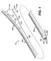
- FIGURE 1is a schematic illustration of an endoscopic sheath and track.
- FIGURE 1Ais a schematic illustration of an endoscope inserted into a handle having a hinged latch in an open configuration.
- FIGURE 1Bis a schematic illustration similar to that of Figure 1A showing the hinged latch in a closed position and feeding tube and carrier being advanced on a track.
- FIGURE 2is a schematic illustration of the distal end of the sheath of Figure 1 showing a carrier being advanced on the track.
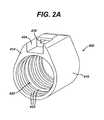
- FIGURE 2Ais a schematic isometric illustration showing the proximal end of the endcap.
- FIGURE 3illustrates different sections of a track disposed on a sheath.
- FIGURE 4is a top view illustration of a portion of a track.
- FIGURE 5is a cross-sectional illustration of a track supported on a sheath (it being understood that the sheath may be formed of a thin film that would not maintain the circular configuration shown in Figure 5 absent an internal member, such an endoscope, being disposed within the sheath).
- FIGURE 6is a schematic illustration of a feeding tube carrier in accordance with one embodiment of the present invention.
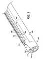
- FIGURE 7is a schematic illustration of a distal portion of a sheath and track showing a carrier advanced to a distal position on the track, and with an indicator tab extending through a slot in an endcap to be viewable by an endoscope.
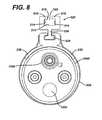
- FIGURE 8is a schematic illustration showing the distal end of an endoscope being advanced through a sheath, with the sheath, track, and carrier shown in cross-section.
- FIGURE 9is a schematic illustration of a distal portion of a sheath, track, and carrier, and illustrating the carrier and a feeding tube advanced to a distal position on the track.
- FIGURE 10is a schematic illustration of a feeding tube having a feature for providing sliding engagement with a track.
- FIGURE 11is a schematic illustration of the proximal portion of the feature shown in Figure 10.
- FIGURE 12is a schematic illustration of a port for use in maintaing the feeding tube in a desired position in the gastrointestinal tract after the feeding tube is positioned and the track has been withdrawn from the GI tract.
- FIGURE 13is a schematic side view illustration of a distal portion of the feeding tube shown in Figure 10, illustrating a distal portion of a passageway (in phantom) through which nutrients may be directed, such that the distal portion of the passageway does not have to bend or curve to communicate with a distal feeding port, with the portion of the feeding tube extending distally of the distal feeding port being inclined with respect to the passageway, and the figure illustrating weights (in phantom) which may be employed at a distal end of the feeding tube.
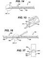
- FIGURE 14is a schematic illustration of a distal portion of a member which may be employed to maintain the feeding tube in a desired position during removal of the endoscope and the carrier from the patient's GI tract.
- FIGURE 15is a schematic illustration of the distal end of the member of Figure 14 and showing contact surfaces positioned, sized, and/or shaped for engaging contact surfaces on the proximal end of a rail feature associated with a feeding tube.
- FIGURE 16is a schematic illustration of the distal portion of the member of Figure 14 positioned with respect to the proximal end of the rail feature on the feeding tube.
- FIGURE 17is a schematic bottom view illustration of adjacent portions of the rail feature on the feeding tube and the member of Figure 14.
- FIGURE 18illustrates introducing an endoscope in a medical device (which medical device can include a handle, sheath, endcap, and track) into the GI tract of a patient, such that the endcap and the distal end of the track are positioned in the small intestine (such as in the jejunum).
- a medical devicewhich medical device can include a handle, sheath, endcap, and track
- the endcap and the distal end of the trackare positioned in the small intestine (such as in the jejunum).
- FIGURE 19illustrates advancing a carrier and a feeding tube together on the track after the endoscope and track have been positioned as shown in Figure 18, so that the distal end of the feeding tube is positioned in the jejunum.
- FIGURE 20illustrates feeding a member distally to a position behind the feeding tube to hold the feeding tube in place in the GI tract while the endoscope and medical device (which medical device can include a handle, sheath, endcap, and track) are removed in a proximal direction from the patient.
- endoscope and medical devicewhich medical device can include a handle, sheath, endcap, and track
- FIGURE 21illustrates the feeding tube positioned to extend from outside the mouth to the small intestine.
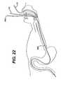
- FIGURE 22illustrates providing a transfer tube through the nose.
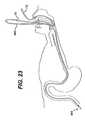
- FIGURE 23illustrates associating an end of the transfer tube with the proximal end of the feeding tube.
- FIGURE 24illustrates the proximal end of the feeding tube pulled through the throat and the nasal cavity (such as with the transfer tube of Figure 23) such that the proximal end of the feeding tube extends from the patient's nose (from a nostril).
- FIGURE 25illustrates positioning an endoscope within a medical device (which medical device can include a handle, sheath, endcap, and track) into the GI tract such that the endcap and the distal end of the track are disposed in the stomach, such as for use in a PEG tube feeding method, and Figure 25 illustrating a cannula/needle for providing a percutaneous incision through the abdominal wall can be transilluminated with a light source associated with the endoscope.
- a medical devicewhich medical device can include a handle, sheath, endcap, and track
- Figure 25illustrating a cannula/needle for providing a percutaneous incision through the abdominal wall can be transilluminated with a light source associated with the endoscope.
- FIGURE 26illustrates removing the needle from the cannula and introducing a looped guidewire through the cannula, and illustrating the distal end of the endoscope, endcap, sheath, and track passing through the loop of the looped guidewire.
- FIGURE 27advancing a PEG tube (such as a PEG tube having a length substantially less than the length of the track) on the track, with the PEG tube disposed on the track such that a first end of the PEG tube to be positioned inside the body is advanced ahead of a second end of the PEG to be positioned through the percutaneous incision, and showing the first end of the PEG tube being advanced off of the track.
- a PEG tubesuch as a PEG tube having a length substantially less than the length of the track
- FIGURE 28illustrates the second end of the PEG tube advanced off of the rail and grasping a length of suture extending from the second end of the PEG tube with the looped guidewire.
- FIGURE 29illustrates pulling the suture loop and the second end of the PEG tube through the percutaneous incision and seating a bumper member at the first end of the PEG tube against the inside surface of the gastric wall, with the endoscope positioned to provide viewing of the seating.
- FIGURE 30illustrates the medical device and endoscope removed from the GI tract and the external portion of the PEG tube adapted for introducing nutrients through the abodiminal wall.
- FIGURE 31illustrates positioning an endoscope (such as a gastroscope) disposed in a medical device (which medical device can include a handle, sheath, endcap, and track) into the GI tract such that the endcap, the distal end of the gastroscope, and the distal end of the track are disposed in the stomach, such as for use in a JET-PEG tube feeding method, with Figure 31 also showing the endoscope can be used to transilluminate the abdominal wall, such that a needle/cannula can be used to make and/or pass through a small incision into the stomach.
- a medical devicewhich medical device can include a handle, sheath, endcap, and track
- Figure 31also showing the endoscope can be used to transilluminate the abdominal wall, such that a needle/cannula can be used to make and/or pass through a small incision into the stomach.
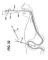
- FIGURE 32illustrates removing the needle and introducing a looped guidewire through the cannula, after which the medical device (with gastroscope disposed therein) can be advanced through the looped guidewire, with the distal end of the medical device and the distal end of the gastroscope being advanced into the jejunum (such as past the Ligament of Treitz)
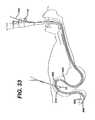
- FIGURE 33illustrates positioning a feeding tube (such as a feeding tube having a length substantially less than the length of the track) and carrier on the track, and advancing the feeding tube along the track until the distal end of the feeding tube is positioned in the jejunum and can be viewed by the endoscope.
- a feeding tubesuch as a feeding tube having a length substantially less than the length of the track
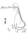
- FIGURE 34illustrates retracting the medical device and gastroscope proximally into the stomach, while holding a member positioned proximally behind the feeding tube to push the feeding tube off the distal end of the track, and illustrating grasping a length of suture extending from the feeding tube with the looped guidewire.
- FIGURE 35illustrates pulling the suture and an end of the feeding tube through the incision through the abodiminal wall, and leaving a distal end of the feeding tube in the jejunum.
- FIGURE 36illustrates the external portion of the feeding tube adapted for introducing nutrients through the abodiminal wall, with the distal end of the feeding tube being positioned in the jejunum.
- FIGURE 37illustrates the feeding tube in place with the gastroscope and medical device removed.
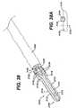
- FIGURE 38illustrates an endcap loading element which can be used to an endcap on the distal end of an endoscope.
- FIGURE 38Ais a cross-sectional schematic illustration of a flexible prong of the endcap loading element.
- FIGURE 39illustrates the endcap loading element disposed on the distal end of the endoscope, and the endoscope disposed in the sheath, with the flexible prongs of the endcap loading element disposed within the sheath and engaging an outer surface of the endoscope, with an O-ring compressing the flexible prongs and positioned against the proximal face of the endcap, and with a distal portion of the endcap loading element extending through the bore of the endcap.
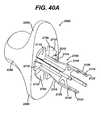
- FIGURE 40illustrates a handle sliding proximally on the endcap loading element to be positioned against the distal face of the endcap.
- FIGURE 40Ais a schematic illustration showing the proximal face a handle and showing an endcap loading element extending into a central bore in the handle.
- FIGURE 41illustrates a ring which can be attached to a distal portion of the endcap loading element.
- FIGURE 42illustrates pulling distally on the ring while pushing proximally on the handle, to provide a pushing force on the distal face of the endcap with the handle, while providing a pulling traction force on the outer surface of the endoscope with the flexible prongs, such that the end cap and the O-ring slide off of the endcap loading element and onto the distal end of the endoscope.
- FIGURE 43illustrates a schematic isometric view of an apparatus that engages an internal surface of an endoscope and can be used to push an endcap onto an endoscope.
- FIGURE 44is cross-sectional, schematic illustration of the apparatus of FIGURE 43.
- FIGURE 45is a schematic isometric illustration showing the distal end of an endoscope, the endcap, and the forward portion of the apparatus of FIGURE 43 with a portion of the apparatus being inserted into a working channel of the endoscope.
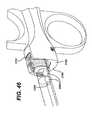
- FIGURE 46is a schematic isometric illustration showing expansion of a portion of the apparatus inserted into the working channel of the endoscope.
- FIGURE 47is a schematic isometric illustration showing rearward movement of an actuator of the apparatus of FIGURE 43 to push the endcap onto the endoscope in a first direction while pulling the endoscope in the opposite direction.
- FIGURE 48is a cross-sectional, schematic illustration of a portion of the apparatus of Figure 43.
- FIGURE 49is a cross-sectional, schematic illustration of a portion of the apparatus of Figure 43.
- FIGS 1 and 2illustrate a medical apparatus 10 according to one embodiment of the present invention.
- apparatus 10can include a handle 100, a flexible catheter or sheath 200 extending from handle 100, a flexible track 300 disposed on the sheath 200, and an endcap 400 disposed at the distal end of sheath 200.
- Handle 100 and flexible sheath 200can each be sized to receive an endoscope therethrough.
- Apparatus 10can also include a carrier 500 which is adapted to slidably engage track 300, as shown in Figure 2.
- Endcap 400can be sized and shaped to engage the distal end of an endoscope, such as an endoscope 1000 as shown in Figure 2.
- Endoscope 1000can be any commercially available endoscope, such as a gastroscope or colonoscope having an articulating distal section, and including a viewing element 1100 and a working channel 1200. Any suitable endoscope, including without limitation gastroscopes and pediatric colonscopes can be used with the present invention.
- Suitable endoscopes for use with the present inventioninclude, without limitation, model PCF100, PCF130L, PCF140L, or PCF160AL endoscopes manufactured by Olympus Corporation of Japan.
- the handle 100, sheath 200, and endcap 400can be sized to receive various diameter endoscopes, such as, but not limited to, endoscopes having a diameter from about 9 mm to about 14 mm.
- the sheath 200is preferably formed of a thin, light weight, drapable polymeric film material which can be relatively soft and elastically extensible, and which has substantially no torsional stiffness and no torsional load carrying capability.
- drapableit is meant that the sheath does not maintain a circular or other regular cross-sectional shape in the absence of an internal structure (such as an endoscope) supporting the sheath.
- the sheath 200can be formed of a material having an elastic modulus of less than about 20 ksi , more particularly less than about 15 ksi, still more particularly less than about 10 ksi, and even more particularly less than about 7 ksi.
- the sheathcan be formed of a material having a yield strength of less than about 500 psi, more particularly less than about 300 psi, still more particularly less than about 200 psi, and still more particularly less than about 125 psi.
- the sheathcan be formed of a material having a yield strength of between about 90 psi and about 120 psi.
- the elastic modulus and yield strengthcan be determined as an average of five or more measurements, and can be determined using ASTM test #D882 (Standard Test Methods for Tensile Properties of Thin Plastic Sheeting) using a gage length of 4.0 inch, a gage width of 1.0 inch, a test thickness equal to the thickness of the film (e.g about 0.005 inch), and a test machine speed of 0.4 in/minute.
- the sheathcan be formed of a film have a modulus of less than about 7 ksi, a yield strength of less than about 125 psi, and a tensile strength at break (measured according to ASTM D 638) of at least about 1 M Pa (mega Pascal), more particularly at least about 5 Mpa, and still more particularly about 10 Mpa or greater.
- the sheathcan be formed of a film having a tensile elongation (measured using ASTM D 638)of at least about 200 percent, more particularly at least about 500 percent, and still more particularly about 800 percent or more.
- the modulus, yield strength, tensile strength, and elongationare determined as mean of at least five measurements.
- the sheath 200can be inserted over the insertion length of the scope without use of a lubricant.
- the sheath 200can have a non-smooth, textured inner surface 210 that prevents the inner surface of the flexible sheath from "sticking" to outer surface of the insertion portion of the endoscope.
- the textured inner surfacecan also aid in gripping the endoscope through the sheath 200, such as for example if it is desired to rotate the sheath and endoscope together.
- the inner surfacecan be textured and the outer surface can be generally smooth, or both the inner and outer surfaces may be textured.
- the inner surface of the sheath 200may have the same texture as the outside surface, be relatively more textured than the outer surface, or be relatively less textured than the outside surface.
- the textured inner surfacecan be provided with elevated portions, depressed portions, or combinations of elevated and depressed portions.
- the inner surfacecan include randomly spaced bumps or protrusions, or alternatively, can be provided by raised portions (such as bumps, ribs or protrusions) that occur at regularly spaced intervals, which intervals may be of generally uniform spacing.
- the texture of the inner surfacecan be measured in terms of a roughness average measurement, where "roughness average” or "Ra'' is the arithmetic average of the absolute values of the measured profile height deviations divided by an evaluation length, as set forth on page 728 of the 27st edition of Machinery's Handbook, 2004 , incorporated herein by reference.
- the roughness averagecan be measured using optical interferometry with a Zygo NewView 100 3D Imaging Surface Structure Analyzer marketed by Zygo Corporation of Middlefield, Conn. The following measurement parameters and analysis parameters can be used:
- Measurment ParametersAcquisition Mode is "Scan”; Camera Mode is 320x240 Normal; Phase Controls (AGC is “ON”; Phase res is “High”; Min Mod is 1%; Min Area size is 7; Discon Action is "Filter”; Connection Order is “Location”; Remove Fringes is “Off”; Image Zoom is 1x); Scan Controls (Scan length is “Extended”; Extended Scan Length is 11000 micro inches; FDA Res is “Low”).
- Filteris "Lowpass”; Filter Type is “Average”; Filter Window Size is 13; Filter High Freq. I/mil; Filter Low Freq. 1/mil; Filter Trim is “Off”; Remove is “Plane”; Trim is 0; Remove Spikes is “ON”; Spike Height(xRMS) is 1.25; Data Fill is “ON”; Data Fill Max is 25.
- the measurementscan be made with a 5x Michelson Objective Lens, and the samples can be coated with gold or otherwise coated to provide an generally opaque surface that reflects light. Gold coating can be applied with a Hummer 6.2 Sputtering System.
- the inner surface of the sheath 200can a have a roughness average value Ra of less than about 500 micro inch (.000500 inch), more particularly less than about 400 micro inch, still more particularly less than about 250 micro inch, and still more particularly less than about 150 micro inch.
- the roughness average value of the inner surfacecan be between about 50 and about 500 micro inch, more particularly between about 50 and about 250 micro inch, and still more particularly between about 75 and about 125 micro inch. The roughness average value is determined as a mean of at least five measurements.
- the inner surface of the sheath 200can have a coefficient of friction which is suitable for gripping the endoscope with the sheath 200, but which also allows the endoscope to be positioned within the sheath without excessive effort.
- a suitable inner surfacecan have a coefficient of static friction and a coefficient of sliding friction which can both be less than about 1.0.
- the coefficient of static frictioncan be between about 0.3 and about 0.6 (more particularly between about 0.4 and 0.5) and the coefficient of sliding friction can be between about 0.3 and about 0.6 (more particularly between about 0.4 and about 0.5) using a friction sled formed of Ultem 1000 material.
- the coefficient of static frictioncan be between about 0.2 and about 0.5 (more particularly between about 0.3 and about 0.4) and the coefficient of sliding friction can be between about 0.2 and about 0.5 (more particularly between about 0.3 and about 0.4) using a friction test sled formed of 440C stainless steel.
- the coefficient of static and sliding frictioncan be measured using ASTM test #D1894 (Standard Test Method for Static and Kinetic Coefficients of Friction of Plastic Film and Sheeting). The coefficient of friction is determined as a mean of at least five measurements.
- the sheath 200can be formed of a thermoplastic polyolefin film having a thickness of less than about 0.010 inch, and can comprise polypropylene, polyethylene, and mixtures thereof. In one embodiment the sheath can be formed of a film having a thickness of between about 0.004 to 0.006 inch, more particularly about 0.005 inch.
- One suitable filmis available as Basell Softell Q020F made by Basell NV, Hoofdorp, Netherlands, such as can be provided by Specialty Extrusion, Inc. of Royersford, Pa.
- the handle 100can be formed of any suitable material, including without limitation relatively rigid biocompatible metals and plastics.
- One suitable material from which handle 100 can be formedis molded polypropylene, such as is available as Huntsman 12N25ACS296 from Huntsman Corp. of Houston TX.
- handle 100can have a generally cylindrical proximal section 102 having a proximal opening for receiving an endoscope, and an adjacent distally converging conical section 104.
- the handle 100includes an opening 101 at it's proximal end for receiving an endoscope.
- the handle's internal channel for receiving the endoscopecan include a generally cylindrical channel section 103 (shown in phantom) corresponding to section 102, and a generally conical channel section 105 (shown in phantom) corresponding to section 104.
- the generally conical channel section 105can taper from a relatively larger inner diameter to a relatively small inner diameter as the channel section 105 extends distally.
- a track support structure 120is shown extending from sections 102 and 104 to support a track ramp 130 at an inclined angle with respect to the longitudinal axis of sections 102 and 104.
- Track ramp 130can support the proximal portion of the track 300.
- FIGs 1A and 1Billustrate isometric views of an endoscope 1000 inserted into handle 100.
- a hinged latch 140can be positioned at or adjacent to the proximal end of track 300.
- the latch 140can be hinged to the track ramp 130 or structure 120, such as by a living hinge or a mechanical pin type hinge.
- the latchis shown in an open position in Figure 1A and a closed position in Figure 1B.
- the latchwhen in the closed position, extends over the track 300 at or adjacent the proximal end of the track and can assist in preventing components slidably supported on track 300 from "unzipping" from track 300 or otherwise being dislodged from track 300 during use.
- a carrier 500 and feeding tube 600are shown being advanced by hand in a distal direction along track 300.
- an elastically extensible membercan be employed to provide a distal biasing force on the endoscope and a proximal biasing force on the handle 100.
- the handle 100can include an elastic strap 150 (shown in Figure 18 and 19).
- the elastic strapcan extend from a portion of the handle 100, such as the track ramp 130 or the structure 120, to form a loop that encircles a portion of the endoscope 1000, such an endoscope accessory channel port.
- the elastic strap 150is useful for accommodating variation in endoscope lengths, assists in maintaining tautness of the sheath, and assists in maintaining engagement of the endoscope in the handle.
- the elastic strapcan be employed to compensate for length changes due to scope bending, and to provide a reslient biasing force urging the endoscope distally into the handle and sheath.
- a relatively inelastic strapcould be used, and a biasing member could be employed in the handle or sheath to maintain the sheath and track from pleating or otherwise "bunching" on the endoscope.
- the strapcould be generally inextensible, and the handle could be formed of an elastically extensible material or geometry, such that the length of the handle would be extended when the strap was engaged on relatively longer endoscope.
- Endcap 400can be formed of a thermoplastic elastomer for fitting on the distal end of the endoscope 1000.
- the endcap 400can be formed of a material having a durometer of less than about 100, and more particularly between about 50 and about 90 (as measured using the A scale, 0.120 inch test according to ASTM D2240).
- the endcapcan be pressed onto (e.g. slightly expanded to fit over) the distal end of the endoscope with the distal end of the endoscope being gripped by the endcap 400.
- One suitable material from which endcap 400 can be formedis molded Santoprene brand thermoplastic elastomer. Providing an endcap 400 from a material such as a thermoplastic elastomer can be desirable in that such an endcap 400 can be pressed onto the distal end of the endoscope, as described in more detail below.
- the endcap 400can include a generally cylindrical body portion 410, a distal face 412, a proximal face 414, and a central bore opening 420 therethrough for receiving the distal end of the endoscope 1000.
- the endcap 400can have internal, circumferentially extending grooves 422 spaced apart along the length of the internal surface of central bore opening 420.
- a track recess 424( Figure 2A) can provided in the upper half of body portion 410.
- the recess 424can extend distally from the proximal face 414, and can be sized and shaped to receive the distal end of the track 300.
- the proximal edge of the bore opening 420can be tapered or chamfered to assist in pressing the endcap onto the distal end of the endoscope.
- the endcap 400can also include a slot 430 ( Figure 2 and 2A) extending through at least a portion of the body portion 410 and opening on the distal face 412. Slot 430 can extend distally from a surface bounding track recess 424, to be disposed with respect to track 300 to be at generally the same "o'clock" position as track 300. Slot 430 can be sized and shaped to receive a tab or other indicator device, as described below.
- the proximal end of slot 430can be generally aligned with channel 320 in track 300 (described below), and the distal end of slot 430 can be inclined radially inwardly as the slot 430 extends from recess 424 in the distal direction, such that a tab or other indicator device extending through slot 430 is directed distally and radially inwardly to be viewable by the optics of the endoscope 1000.
- the Endcap 400can be joined to the distal end of the sheath 200 by any suitable method, such as ultrasonic welding.
- Track 300can be supported by sheath 200, and can extend from handle 100 to the endcap 400.
- Figure 3shows track 300 supported on sheath 200 with a portion of the track shown in phantom.
- Figure 4illustrates a top plan view of the track 300
- Figure 5illustrates a cross-sectional view of track 300 supported by sheath 200.
- the sheath 200is shown in cross-section as it would appear if disposed on an endoscope for illustration purposes, with it being understood that, in one embodiment, the wall of the sheath 200 can be generally flaccid and drapable, and lack sufficient stiffness to maintain the shape shown in Figure 5 without the support of the endoscope or other internal support.
- Track 300can be a generally continuous, unitary piece of material which extends longitudinally a length sufficient to reach from a point outside the patient to a point in or distal to the stomach of the patient, such as through the pylorus and into the small intestine.
- Track 300can be formed of a flexible polymeric material, such as extruded polypropelene.
- One suitable material from which track 300 can be formedis Huntsman 23R2Acs321 available from Huntsman Corp. of Houston TX.
- the sheath 200can be joined to the track 300 by any suitable joining method, such as by ultrasonic welding.
- the distal end of the track 300can be over molded onto the end cap 400, or otherwise joined to end cap 400 in recess 424.
- the handle 100can be joined to the proximal end of the sheath 200 and the proximal end of the track 300 by any suitable method, such as by ultrasonic welding.
- Track 300can include a generally C shaped channel body 310 defining an inverted T-shaped channel 320 in cross section.
- the body 310can include floor 312, upstanding side walls 314, and inwardly extending prongs 316.
- the body 310can also include a plurality of circumferentially extending side tabs 330 extending outwardly from body 310. Adjacent tabs 330 on each side of the track 300 can be spaced apart, such as by the scalloping (shown in Figure 3 in phantom), or by other spacing methods, such as notching, to maintain the flexibility of the track 300.
- the tabs 330are shown joined to the inner surface 210 of the sheath 200. Tabs 330 can be joined to the inner surface 210 by any suitable means, such as with adhesive or other bonding methods.
- the tabs 330can be employed to stabilize the track 300 with respect to the endoscope when the endoscope is positioned in sheath 200.
- the tabshelp to maintain radial alignment of the axis of symmetry of the track channel 320 with respect to the endoscope 1000.
- the sheath 200 and the track 300can be rotated circumferentially as a unit about the endoscope 1000 to different o'clock positions, and the tabs 330 help to maintain the track 300 (and channel 320) in proper radial orientation with respect to the endoscope.
- the desired radial orientation of channel 320is illustrated in Figure 5, with the cross-sectional centerline and axis of symmetry of channel 320 being generally aligned with a radial line extending from the center of the the endoscope.
- the track 300has at least one portion which has a greater flexibility than another portion of the track.
- the track 300can include a portion having a bending flexibility and axial flexibility that is greater than the bending flexibility and axial flexibility of another portion of the track.
- the track 300is shown schematically to have three sections of different flexibility.
- Section Awhich can be the distal most portion of the track 300, can be the most flexible portion of the track in both bending and axial extension.
- Section Acan be associated with the distal most portion of the endoscope, such as an articulating portion of the endoscope.
- Section Bcan be relatively less flexible (more stiff) than Section A.
- Section Ccan be the proximal portion of the track 300 and can be relatively less flexible than region B.
- Section Acan extend about 10 inches
- Section Bcan extend about 26 inches.
- the length of the track 300can be at least about 50 inches.
- Sections A and Bare interrupted at intervals along their respective lengths to reduce the bending stiffness and the axial stiffness of the regions, while Section C can be generally uninterrupted.
- the interruptions in Sections A and Bare provided by a series of slits 340.
- the slits 340 on the two sides of the track body 310are staggered (longitudinally offset) relative to each other such that the slits on one side of the track body 310 are not aligned with the slits on the other side of the track body 310.
- each slit 340 on one side of the trackis positioned halfway between the two adjacent slits on the opposite side of the track.
- Each of the tabs 330can be positioned between a pair of adjacent slits 340.
- the slits 340can have a width (measured parallel to the length of channel 320) of less than about 0.010 inch, more particularly, less than about 0.005 inch.
- the slits 340can be formed by any suitable knife or other cutting instrument.
- the width and staggering of the slits 340can provide sufficient flexibility of the track 300, while preventing a member slidably disposed in the track from "unzipping" from the carrier, or “popping out of” the track, such as by deflection of prongs 316, at positions where the endoscope is bent (or other configuration where the track is bent or otherwise to take on a curved configuration).
- the provision of selectively placed interruptions in the trackpermits the track to follow the curvature of the endoscope without significantly increasing the bending stiffness of the assembly of the sheath 200 and endoscope.
- the slits 340extend through the full thickness of the track (thickness as measured in the vertical direction in Figure 5). Additionally, the slits can extend from one side of the track to extend across the full the width of one of the prongs 316, and the slits can extend at least halfway across the floor 312.
- each of the slits 340can extend through the full thickness of the track. Additionally, depending upon the location of the slits 340 along the length of the track, the slits 340 can extend more than halfway, but not fully across the width of the track. For instance, the slits 340 extend across the longitudinal centerline of the track in Section A of Figure 3. Referring to Figure 5, the dimension W illustrates the width of a slit extending more than halfway, but not fully across the width of the track.
- the spacing 342 (Fig 3) between slits 340 on the same side of the track 3090can be about .120 to about .130 inch in Section A and about .250 inch in Section B.
- the staggered arrangement of slits 340 that extend beyond the centerline of the trackcan provide the advantage that the track 300 does not have a longitudinally continuous load path for carrying tensile loads or bending loads.
- the staggered arrangement of slits 340can be viewed as providing bending sections (indicated by reference number 344 in Figure 4) in the track 300.
- the bending sections 344can have a length 346 ( Figure 4) defined by the amount the slits 340 on opposite sides of the track overlap, and the bending sections 344 have a width 348 defined by the longitudinal spacing of one slit from the immediately adjacent slit extending from the opposite side of the track.
- the length 346can be about 0.038 inch to about 0.040 inch in Section A
- the width 348can be about 0.0625 inch.
- FIG. 6illustrates carrier 500
- Figure 7illustrates carrier 500 advanced to distal most position on track 300.
- Carrier 500can extend from a proximal end 502 to a distal end 504.
- the length of carrier 500can be a length sufficient to reach from a point outside the patient to a point within, or distal to, the patient's stomach. In one embodiment, the length of carrier 500 can be at least about 100 cm, and more particularly at least about 72 inches.
- the carrier 500can include a body 520, a generally vertically extending web 530, and a track engaging rail 534.
- Carrier 500slidably engages track 300, with rail 534 being sized and shaped to be slidable within channel 320 of track 300.
- Carrier 500can be of unitary construction, and can be molded or otherwise formed of a suitable material. In one embodiment, carrier 500 is formed of a relatively low friction materials, such as extruded PTFE (Teflon).
- Figure 8provides a cross-sectional illustration of carrier 500 supported on track 300, with the distal end of endoscope 1000 illustrated being advanced through the cross-section to illustrate one position of components on the endoscope's distal end relative to the position of the track 300.
- the web 530extends generally radially inwardly from body 520, to position the rail 534 radially inward of the carrier body 520.
- the cross-section of web 530 and rail 534, together,can provide a generally inverted "T" configuration.
- the carrier body 520can include a channel 522.
- Channel 522can extend substantially the full length of body 520.
- the channel 522can be bounded by a channel floor 512 and oppositely facing sidewalls 514.
- the body 520can also include inwardly extending prongs 516 having oppositely facing sides 518 which are spaced apart to define the throat of the opening of channel 522.
- the distal most portion of the track engaging rail 534can extend distally beyond body 520 to provide a flexible indicator tab 536.
- Tab 536can be sized and shaped to be received by slot 430 in endcap 400.
- the tab 536will be viewable by the optics of endoscope 1000 once the carrier 500 has reach its distal most position on track 300. Referring to Figures 7 and 8, the tab 536 can be viewed through endoscope optics element 1100 as tab 536 is advanced distally and radially inwardly,from the distal end of slot 430.
- the carrier 500has at least one portion which has a greater flexibility than another portion of the carrier
- the carrier 500can include a body 520 having a distal portion 520A having a bending flexibility and axial flexibility that is greater than a more proximal body portion 520B of the carrier.
- the carrieris shown schematically to have two sections of different flexibility.
- Carrier section 520Acan be the distal most portion of the carrier, and can be the most flexible portion of the carrier in both bending and axial extension.
- Section 520Acan have a length of at least about 2 inches. In one embodiment, the length of Section 520A is between about 4 inches and about 10 inches, and more particularly, the length of section 520A can be between about 6 and about 8 inches.
- body section 520Ais shown interrupted at intervals along its length to reduce the bending stiffness and the axial stiffness of the distal portion of the body 520.
- the interruptionscan be provided by a series of slits 540.
- the slits 540 on the two sides of the carrier body 520are staggered (longitudinally offset) relative to each other such that the slits on one side of the body 520 are not aligned with the slits on the other side of the body 520.
- each slit 540 on one side of the carrier bodyis positioned axially halfway between the two adjacent slits on the opposite side of the track.
- Adjacent prongs 516can be separated by slits 540.
- the flexible tab 536 and the slits 540can help to prevent the distal portion of the carrier 500 from “jumping out” of or “unzipping from” the track.
- flexible tab 536can "bridge” the space between the slits 340 in track 300 to help prevent the carrier from being discharged radially from the track 300.
- the width and staggering of the slits 540can also provide sufficient flexibility of the carrier 500, while preventing a member slidably disposed in the carrier from "unzipping" from the carrier, or "popping out of” the carrier.
- the slits 540can extend through the full thickness of the track (thickness as measured in the vertical direction in Figure 8). Additionally, the slits can extend from one side of the track to extend across the full the width of one of the prongs 516, and the slits can continue through at least a portion of the floor 512. Each of the slits 540 can extend through the full thickness of the track body 520, and each of the slits 540 can extend more than halfway, but not fully across the width of the track.
- the spacing 542 ( Figure 6) between slits 540 on the same side of the carrier bodycan be between about 0.1 inch and about 0.6 inch in carrier body portion 520A.
- the staggered arrangement of slits 540provide the advantage that the carrier body portion 520A does not have a longitudinally continuous load path for carrying tensile loads or bending loads.
- Feeding tube 600can be used with the track 300 and the carrier 500.
- Feeding tube 600can have a proximal end 602 and a distal end 604.
- Feeding tube 600can include a feeding tube body 610 having a nutrient passageway 620 for passing nutrients, and a feature 660 adapted to provide releasable engagement of the feeding tube 600 with another member.
- the feature 660can include a rail for providing sliding engagement of the feeding tube with a track or the carrier 500.
- the passageway 620can extend from proximal end 602 to an exit port 622 through which nutrients exit the passageway 620 and enter the patient's GI tract.
- the portion of the feeding tube 600 extending distally of exit port 622can be inclined with respect to the longitudinal axis of the passageway 620, as shown in Figures 10 and 13, and with exit port 622 having a generally tapered, elongated configuration. Accordingly, as shown in Figures 10 and 13, the passageway 620 can be generally parallel with respect to the longitudinal axis of the feeding tube 610, and the passageway 620 does not bend or curve to communicate with the exit port 622, except to the extend the tube 610 itself is bent.
- passageway 620run substantially straight to exit port 622 and the distal tip portion of the feeding tube inclined with respect to the passageway 620 can provide the advantage that passageway 620 can be easily cleaned, such as by running a wire from the proximal entrance of the feeding tube through the passageway 620 and out through exit port 622.
- feeding tube 600can include one or more suction ports positioned either proximally or distally of exit port 622. Suction ports can be used to hold the distal end of the tube 600 in a desired position within the body once the tube 600 is placed, and prevent migration of the feeding tube 600 during feeding.
- a suction port 680is shown positioned distally of exit port 622. Suction port 680 can include a plurality of radially inwardly extending tabs 682 which can engage and hold tissue when tissue is drawn into the tube 600 by vacuum applied to suction port 680.
- the tabs 682can be formed by cutting or slitting the outer wall of tube body 610 to create the tabs 682, or tabs 682 can be provided in a separate member, such as a metallic or non metallic insert that is formed to include tabs 682, and which is positioned in an aperture in the wall of tube body 610.
- Vacuumcan be communicated to suction port 680 through a vacuum passageway (not shown) which communicates with, or extends separately of, nutrient passagaeway 620.
- Weights 690can be disposed in the distal end of tube 600 to assist in maneuvering and positioning the feeding tube 600.
- the feature 660can extend along at least a portion of the length of feeding tube 600.
- the feature 660is shown extending along some, but not all of the length of the feeding tube 600.
- Feature 660can extend from a proximal end 662 of feature 660 to a distal end 664.
- the proximal end 662 of the feature 660can be spaced from the proximal end of the feeding tube 600 by a distance L, so that the portion of the feeding tube 600 which extends through the throat and/or nose of the patient when the feeding tube 600 is in place does not irritate the patient or interfere with feeding.
- the distance Lcan be between about six inches and about 24 inches, and in one embodiment is about 18 inches.
- the feature 660can be integrally formed with the tube body 610 (such as by molding or extruding). Alternatively, the feature 660 could be manufactured separately from tube body 610, and subsequently attached to body 610, such as by use of any suitable bonding or joining method. Feature 660 can be sized and shaped to permit the feeding tube 600 to releasably engage another member, such as track 300 or carrier 500, such as by sliding engagement. In Figure 9, the feeding tube 600 is shown slidably supported on carrier 500.
- the feature 660can comprise a rail 666 and a web 668, with web 668 extending generally radially from tube body 610 to support rail 666 in spaced relationship from tube body 610.
- rail 666is positioned in channel 522, with web 668 extending through the throat of channel 522.
- slidably supporting the feeding tube 600 on carrier 500 while slidably supporting the carrier 500 on track 300is advantageous in providing for smooth, relatively low friction positioning of feeding tube 600 within the patient.
- feeding tube 600could be slidably supported directly on track 300, such as by having rail 666 engage track 300 directly.
- the track 300could be coated with Teflon or any other suitable low friction coating.
- Figure 11illustrates the proximal end 662 of feature 660.
- a tapered surface 672can be provided at proximal end 662 to prevent tissue from being caught or pinched as web 668 and rail 666 slide with respect to the channel 522 of carrier 500.
- the proximal end of rail 666can be formed, such as by tapering, to provide contact surfaces 674 disposed at the proximal end of rail 666, on either side of web 668.
- Contact surfaces 674can be angled with respect to the longitudinal axis of the feeding tube 600 (in Figure 11 the surfaces 674 are inclined to extend outwardly as they extend distally).
- the contact surfaces 672provide a surface at which a force can be provided to feature 660 in order to push the feeding tube 600 distally along carrier 500.
- the orientation of the contact surfaces 672can be selected with respect to the longitudinal axis of the feeding tube 600 such that the force applied to push the tube 600 distally on carrier 500 does not tend to push the feature 660 out of the channel 5
- the carrier 500 and the feeding tube 600 with feature 660can be packaged together.
- the carrier 500 and feeding tube 600could be packaged together, with the feeding tube 600 pre-assembled on the carrier 500 such as by sliding engagement of the tube with the carrier 500.
- the assembly of the carrier 500 with the tube 600 supported along the length of the carriercan be unpackaged (such as from sterile packaging) at the point of use, and the assembly of the carrier 500 and tube 600 could be advanced along the track 300.
- Figure 14is a side view illustration of the distal portion of a feeding tube positioning member 700.
- Member 700can be used to push the feeding tube distally along the carrier 500 and/or to maintain the feed tube 600 in a desired position in the GI tract as the endoscope is withdrawn from the patient.
- Figure 15is an enlarged illustration of the distal end of the member 700.
- Figure 16illustrates the member 700 positioned to maintain the feeding tube 600 in a desired position
- Figure 17is an enlarged bottom view of the engagement of the distal end of member 700 with proximal end 662 of feature 660 on feeding tube 600.
- the length of member 700can be at least about 36 inches so that the member 700 can extend from a point outside the patient to engage the contact surface 672 on the feeding tube 600 when the feeding tube is positioned in a desired location in the patient's GI tract.
- the member 700can have a structure similar to that of the carrier 500.
- member 700can have a different cross-sectional shape.
- the member 700can include a body portion 710, which may include slits 740 to provide flexibility.
- the member 700can include a rail 766 and a web 768, with web 768 extending from body 710 to support rail 766 in spaced relationship body 710. Rail 766 can be sized and shaped for sliding movement within channel 520 of carrier 500.
- the distal end 702 of member 700can have a tapered surface 772 on body portion 710.
- the distal end of rail 766can be formed to have a V shaped notch with two surfaces 774 being provided to engage surfaces 674 on the feeding tube 600.
- the surfaces 774are positioned distally of the surface 772 and are sized and shaped to contact surfaces 674 on feeding tube 600 such that the rail 766 of member 700 can be employed to exert a force on rail 666 of the feeding tube which force is generally parallel to the rail 766 and rail 666.
- Such surfacescan provide a desired longitudinally directed force without a radial force component, or other force component that might urge feeding tube 600 out of the carrier 500 in an undesired manner.
- the endoscope with sheath 200 and track 300can be positioned in a patient such that the distal end of the endoscope is positioned at a desired position within the GI tract for feeding tube placement.
- the feeding tube 600can be positioned on carrier 500 by sliding the feeding tube onto carrier 500 outside of the patient (or the feeding tube 600 and carrier 500 can be provided in a pre-packaged assembly), and the carrier 500 and feeding tube 600 can then be advanced together along track 300 to a desired position in the GI tract, such as with the distal portion of the feeding tube positioned in the stomach or small intestine.
- the tab 536 on carrier 500can be viewed through the endoscope optics once the tab 536 extends through the endcap 400, thereby providing visual indication that the carrier and feeding tube have reached the desired position.
- the carrier 500could be advanced to along the track 300, and then the feeding tube 600 could be advanced along the carrier 500 to the desire position.
- feeding tube positioning member 700can be employed to maintain the position of the feeding tube during removal of the other components.
- the member 700can be inserted in carrier 500 (with rail 766 positioned in channel 520 of carrier 500 so that member 700 slidably engages carrier 500) and the member 700 can be advanced distally along the carrier 500 until the distal end of the member 700 is adjacent the proximal end 662 of the rail 666 on feeding tube 600.
- the member 700can be held in place (such as by the hands of the physician, a physicians assistance, or a fixture) to maintain the member 700 stationary with respect to the endoscope, sheath, track, and carrier, and exerting a force on the feeding tube rail 666 at the interface of surfaces 774 and surfaces 674, thereby "blocking" the feeding tube 600 from backing up proximal during withdrawal of the endoscope and other components.
- Figures 18-24illustrate steps which may be employed in a method for positioning a feeding tube according to one embodiment of the present invention.
- the endoscopecan be inserted into the sheath 200, with the endcap 400 positioned at a distal end of the sheath 200, the handle 100 positioned at a proximal end of the sheath 200, and with the track 300 extending along the sheath 200 from the endcap 400 to the handle 100.
- sheath assemblyshall refer to the assembly of the sheath 200, handle 100, endcap 400, and track 300.
- the sheath assembly and endoscopecan be inserted into a naturally occurring body opening, such as the mouth, and the sheath assembly with endoscope can be advanced so that the distal end of the endoscope and the endcap 400 are positioned at a desired location, such as the small intestine.
- Figure 18illustrates the sheath assembly positioned in the GI tract of a patient, with the track 300 extending from a position outside the body to a position in the small intestine.
- the feeding tube 600can be positioned on the carrier 500 outside of the patients body, such as by sliding the feeding tube rail 666 in the channel 520 of the carrier 500 until the feeding tube 600 is positioned along the length of the carrier 500, with the distal end of the feeding tube positioned at or adjacent to the distal end of the carrier 500. Referring to Figure 19, the carrier 500 and feeding tube 600 can then be advanced (such as by hand in the direction of arrow 2) together along track 300, with the carrier and feeding tube being advanced from a position outside the patient to a position where the distal end of the feeding tube is positioned at a desired location (the small intestine in Figure 19).
- the length of feeding tube 600can, in one embodiment, be at least about 140 cm long, and the distal end of the feeding tube can be positioned between about 130 to about 140 cm from the patients incisors.
- a 140 cm length 10 Fr Dobb-Hoff-type feeding tube(available from Viasys Healthcare, Inc.) can be modified to have the rail 666 feature, such as by bonding or otherwise attaching a web and rail to the tube.
- a pediatric colonoscopesuch as an Olympus model PCF 100 pediatric colonoscope can be employed with the sheath assembly.
- the member 700can be advanced distally (such as by hand in the direction of arrow 4) along the track 300 until the distal end 702 of the member 700 makes contact with the proximal end of the rail 666 of feeding tube 600. Then, as the member 700 is held stationary with respect to the patient's body and to the sheath assembly, the sheath assembly (with endoscope), and the carrier 500 can be withdrawn proximally from the body, in the direction indicated by arrow 6. Any tendency of the feeding tube 600 to move proximally during withdrawal of the endoscope, sheath assembly, and carrier 500 is prevented by abutting engagement of the surfaces 774 on member 700 with the surfaces 674 on the feeding tube rail 666. Accordingly, the feeding tube 600 is maintained in position by member 700 as the endoscope, the sheath assembly, and the carrier 500 are withdrawn from the body.
- Figure 21illustrates the feeding tube in place in the patient's GI tract after removal of the endoscope, sheath assembly, and carrier 500.
- the feeding tube 600extends from the feeding tube proximal end 602 (positioned outside the patient's body) to the feeding tube distal end 604 (positioned in the small intestine), with the feeding tube 600 extending through the mouth, the esophagus, the stomach, and into the small intestine.
- the feeding tubecan be used in the position shown in Figure 21. However, it may generally be desirable to have the proximal end of the feeding tube extending from the nose.
- Figure 22illustrates use of a transfer tube 12 which may be inserted to extend from the mouth and the nose. The end of the transfer tube extending from the mouth can be coupled to the proximal end 602 of the feeding tube, as shown in Figure 23. The end of the transfer tube 12 extending from the nose can then be pulled so that the proximal end 602 of the feeding tube is redirected to extend from the nose, as shown in Figure 24. A suitable fitting 14 can then be attached to the proximal end 602 of the feeding tube, as shown in figure 24.
- Figures 25-30illustrate an alternative method for positioning a feeding tube within a patient for providing feeding access through an incision in the patient's abdominal wall.
- Figures 25-30illustrate a method of placing a feeding tube in the stomach as an alternative to standard PEG procedures.
- the endoscope disposed within the sheath assemblycomprising the handle 100, sheath 200 and endcap 400 can be advanced through the mouth to position the distal end of the endoscope and the endcap 400 within the stomach of the patient.
- a light source(such as a light source associated with the distal end of the endoscope) can be employed from within the stomach to transilluminate the abdominal wall, so that the position of the endoscope within the stomach can be observed from outside the patient.
- a small, percutaneous incisioncan be made through the abdominal wall, and a needle 22/cannula 24, such as a 14 gauge needle 22/cannula 24 can be inserted through the incision so that the distal tip of the needle and the distal end of the cannula can be positioned within the stomach.
- a needle 22/cannula 24such as a 14 gauge needle 22/cannula 24 can be inserted through the incision so that the distal tip of the needle and the distal end of the cannula can be positioned within the stomach.
- the needle 22can be withdrawn, leaving the cannula 24 to provide an access channel extending from inside the stomach to a point outside the patient.
- a looped guide wire 32can be passed through the cannula, and the endoscope and sheath assembly can be directed to extend through the loop provided by the guide wire 32.
- a relatively short feeding tube 800is illustrated, the feeding tube having a length substantially less than the length of the track 300.
- Feeding tube 800 in this embodimentcan have a length of less than about 3 feet.
- the feeding tube 800can be a commercially available PEG type feeding tube modified to have a feature, such as a rail (not shown), for permitting the feeding tube 800 to slidably engage the track 300 and/or carrier 500.
- the feeding tube 800can be formed by attaching a web and rail to a commercially available PEG feeding tube, such as by bonding or otherwise attaching the web and rail to the feeding tube (alternatively, the feeding tube 800 could be formed by extruding or otherwise forming a feeding tube to have an integral web and rail feature).
- feeding tube 800can include a sealing bumper or bolster 810 and a tapered dilating tip 820.
- the feeding tube 800can advanced distally along the sheath assembly and into the stomach.
- the feeding tube 800can be positioned on track 300 and advanced distally along track 300 to the stomach by using member 700 as a pushing element.
- the feeding tubecan be disposed on carrier 500, and the carrier 500 with feeding tube 800 can be advanced along track 300 to the stomach.
- the feeding tube 800can be pushed off the distal end of the sheath assembly using a member, such as a member 700 described above.
- a suture 830(or other suitable flexible wire or tether) that extends from the tip 820 can be grasped with the guidewire 32 so that the suture 830 can be pulled through cannula 24.
- the suture 830can be pulled (such as with forceps or a hemostat) so that tip 820 extends through the percutaneous incision through the abdominal wall and such that the sealing bumper 810 is positioned against the inside surface of gastric wall (inside surface of the stomach).
- the sheath assemblycan be removed from the patient, and an external seal 840 can be advanced over the feeding tube 800 to fit against the patients skin adjacent the incision.
- the feeding tube 800can be cut to sever the tip 820 from the feeding tube, and a fitting 850 can be positioned on the end of the feeding tube external of the patient.
- a feeding tubeis introduced into the patient through a naturally occurring orifice and pushed distally along an endoscope after the endoscope has been positioned in the stomach. The feeding tube is then pulled through an incision to provide a feeding access channel that extends through an incision to the patient's GI tract.
- Figures 31-37illustrate steps which can be employed in a method for positioning a feeding tube according to another embodiment of the present invention.
- Figures 25-30illustrate a method of placing a feeding tube in the small intestine as an alternative to standard JET-PEG type procedures.
- the endoscope 1000 disposed within the sheath assemblycomprising the handle 100, sheath 200 and endcap 400 can be advanced through the mouth to position the distal end of the endoscope and the endcap 400 within the stomach of the patient.
- a light source(such as a light source associated with the distal end of the endoscope) can be employed from within the stomach to transilluminate the abdominal wall, so that the position of the endoscope within the stomach can be observed from outside the patient.
- a small, percutaneous incisioncan be made through the abdominal wall, and a needle 22/cannula 24, such as a 14 gauge needle 22/cannula 24 can be inserted through the incision so that the distal tip of the needle and the distal end of the cannula can be positioned within the stomach.
- a needle 22/cannula 24such as a 14 gauge needle 22/cannula 24 can be inserted through the incision so that the distal tip of the needle and the distal end of the cannula can be positioned within the stomach.
- the needle 22can be withdrawn, leaving the cannula 24 to provide an access channel extending from inside the stomach to a point outside the patient.
- a looped guide wire 32can be passed through the cannula, and the endoscope and sheath assembly can be directed to extend through the loop provided by the guide wire 32.
- the endoscope and sheath assemblycan be advanced distally from the stomach into the small intestine, as shown in Figure 32.
- a feeding tube 900can be advanced along the length of the sheath assembly such that the feeding tube 900 passes through the loop provided by guidewire 32.
- the feeding tube 900 shown in Figure 3can include a distal portion 904 having a construction like that of the feeding tube 600 described above, and a proximal portion 906 having a construction similar to that of the feeding tube 800 described above.
- the proximal portion 906can include a tapered dilating tip 920 and a bumper or bolster 910.
- the proximal portion 906can be constructed using a PEG feeding tube of the type provided in Corflo-Max brand PEG Kits for Pull Technique or Push Technique, which kits are available from Viasys Healthcare of Wheeling, IL.
- the opening through which food is delivered to the GI tractcan be located in the distal portion 904.
- the feeding tube 900can include a feature, such as a rail (such as the type shown in Figures 10, 11, and 13) on one or both of the portions 904 and 906 such that feeding tube can slidably engage the track 300 and/or the carrier 500.
- the feeding tube 900is positioned on the carrier 500 outside of the patient's body, and the feeding tube 900 and carrier are advanced together along track 300.
- the positioning member 700can be advanced along carrier 500 behind feeding tube 900. If desired, the positioning member 700 can include a grasping clip 715 which can clip onto or otherwise be fastened to member 700 to assist in grasping and pushing the member 700 along carrier 500.
- the endoscope and sheath assemblycan be retracted proximally from the stomach, such that the feeding tube 900 is pushed off the end of the sheath assembly by positioning member 700 as the endoscope and sheath assembly are retracted.
- a length of suture 930 extending from the tip 920can be grasped using the looped guide wire 32.
- the suture 930 and tip 920can be pulled through the incision until bumper 910 is positioned against the inside surface of the stomach, with the portion 904 of the feeding tube including the port through which food is provided being positioned in the small intestine (such as the jejunum).
- an external seal 940can be advanced over the feeding tube 900 to fit against the patients skin adjacent the incision.
- the feeding tube 900can be cut to sever the tip 920 from the feeding tube, along with any unneeded length of the tube, and a fitting 950 can be positioned on the end of the feeding tube external of the patient.
- the endoscope and sheath assemblyare shown removed from the patient's body, and the feeding tube 900 is shown positioned with the distal portion 904 disposed in the small intestine, and with the feeding tube 900 extending from the small intestine through the stomach to pass through an incision through the stomach and through the patient's abdominal wall and skin.
- a feeding tubeis introduced into the patient through a naturally occurring orifice and pushed distally along an endoscope after the endoscope has been positioned in the stomach.
- the feeding tubeis then pulled through an incision to provide a feeding access channel that extends through a percutaneous incision into the patient's GI tract (eg. small intestine).
- a cover or tunnelsuch as around the track 300, carrier 500, and/or the feeding tube, to reduce the risk of contamination of the feeding tube as it is advanced to a desired location, such as for instance from contamination by oral material, such as oral flora.
- the cover or tunnelcan be formed of a thin flexible material (such as for instance a cellophane material or the material from which sheath 200 is formed), and can extend at least partially along the length of the track, carrier and/or feeding tube.
- an assembly of the carrier, feeding tube, and a flexible covercan be provided as a pre-packaged assembly. The carrier, feeding tube, and flexible cover can then be advanced along the track.
- the flexible covercan be disposed on the carrier such that the cover and carrier are withdrawn, leaving the feeding tube in place.
- the sheath 200can be formed to include a tunnel extending over and along the track, such that the carrier and feeding tube can be advanced through the tunnel.
- the trackcould be disposed on the inside surface of a sheath, or on the surface of the endoscope, such that the feeding tube is advanced within the sheath.
- US Serial Numbers 10/440,957discloses a sheath and accessories advanced along an inside surface of a sheath, such as in the embodiment of Figure 6 of US 2004/0230095 . Such an arrangement can be employed, with the feeding tube advanced within the sheath.
- Figures 38-42illustrate a method for positioning and endcap 400 (such as an elastomeric endcap 400) and sheath 200 on an endoscope 1000 prior to inserting the endoscope on the sheath assembly into the patient.
- endcap 400such as an elastomeric endcap 400
- sheath 200on an endoscope 1000 prior to inserting the endoscope on the sheath assembly into the patient.
- it may be difficult to manually load an endoscope into a sheath having an endcapsuch as by gripping the components by hand.
- the desired o'clock orientationmay be inadvertently lost, requiring re-intallation.
- the method and components illustrated in Figures 38-42can be employed to assist in proper installation of an endcap (and associated sheath and track) onto an endoscope. Additionally, the method and components can be employed to intall an endcap on an endoscope even if no sheath and or track is employed.
- an endcap loading elementis shown in the form of a nose cone 2100.
- the nose cone 2100can be disposable, and can be formed of a lightweight material, such as a polymeric material.
- the nose cone 2100can include a body portion 2110 and a plurality of flexible prongs 2120 (six prongs shown in Figure 38).
- the distal end 2102 of the body portion 2110can be rounded or tapered.
- the body portion 2110can include a through hole 2112 which extends through the width of body portion 2110 in a direction transverse to the longitudinal axis of the body portion 2110.
- the body portion 2110 and the prongs 2120can be sized and shaped to pass through the central bore opening 420 of endcap 400.
- the body portion 2110can include a plurality of radial splines 2114 which extend along the length of body portion 2110. Each spline 2114 can be associated with a rounded or sloped prong shoulder 2118. Each prong shoulder 2118 can be associated with a flexible prong 2120. Each flexible prong 2120 can extend proximally from a prong shoulder 2118 to a proximal prong end 2122. Each rounded prong shoulder 2118 can extending radially outward from its associated spline 2114 on the body portion 2110 to the flexible prong 2120 associated with that prong shoulder.
- the radially outward surfaces of the splines 2114can define a first diameter of the nose cone 2100, and the radially outward surfaces of the prongs 2120 can define a second diameter of the nose cone, with the second diameter being greater than the first diameter.
- the radially outer surface of each rounded prong shoulder 2118can be shaped to provide a smooth radial transition from each spline to its associated prong. Accordingly, the rounded prong shoulders 2118, together, provide a smooth radial transition from the first diameter to the second diameter.
- the radially inward facing surfaces of the flexible prongs 2120can be spaced apart (either by being formed in that fashion, or due to an applied force) to receive the distal end of the endoscope 1000.
- the splines 2114, rounded prong shoulders 2118, and the prongs 2120can be circumferentially spaced apart at generally equal angular intervals (e.g. for six splines, six prong shoulders, and six prongs, each associated spline, prong shoulder, flexible prong could be spaced at 60 degree intervals about the circumference of the body portion 2110).
- Each prong 2120can have a slot 2124 formed in the outwardly facing surface, as shown in Figure 38A and Figure 40A. Together, the slots 2124 in the prongs 2120 provide a circumferentially interrupted groove in which an expandable ring, such as a silicone O-ring or Teflon O-ring 2160 can be seated.
- an expandable ringsuch as a silicone O-ring or Teflon O-ring 2160
- the radial thickness 2123 of the prongs 2120 illustrated in Figure 38Acan be sized to take into account various factors, such as the inner diameter and material of the endcap, the outer diameter of the distal end of the endoscope 1000, and the number of prongs 2120 on nose cone 2100, such that when prongs 2120 are disposed between the outer surface of the distal end of the endoscope, and the inner surface of the endcap, the radially inner surface of the endcap is spaced from the outer surface of the endoscope.
- One suitable thickness 2123 when six prongs 2120 are employedis about 0.032 inch.
- the distal end of the endoscope 1000can be inserted between the prongs 2120.
- the O-ring 2160can then be slid over body 2110 of nose cone 2100 and up over the rounded prong shoulders 2118.
- the O-ringcan be stretched over the shoulders 2118 and be seated in the slots 2124 in prongs 2120.
- the O-ringcan thereby provide a radially inward compressive force on the prongs 2120, urging the radially inwardly facing surfaces of the prongs 2120 into engagement with the outer surface of the distal end of the endoscope 1000.
- the endoscope 1000With the nose cone 2100 positioned on the distal end of the endoscope 1000 the endoscope 1000 is loaded onto the sheath assembly (comprising the handle 100, sheath 200, track 300, and endcap 400).
- the endoscopeis loaded onto the sheath assembly such that the body portion 2110 of nose cone 2100 extends distally from the endcap 400, as shown in Figure 39, and such that the proximal face of the endcap 400 abuts against prong shoulders.
- the O-ring 2160 and two proximal prong ends 2122are shown in phantom in Figure 39, as the O-ring and prong ends would be inside the sheath (but can be visible when sheath 200 is made of a substantially transparent film material).
- a handle 2200is shown with a pair of outwardling extending arms 2204 extending from a central hub 2208.
- the hub 2208includes a grooved through bore 2210.
- the through bore 2210has grooves sized and shaped to permit the handle 2200 to slide longitudinally along the splines 2114 of body portion 2110 on nose cone 2100.
- the engagement of the splines 2114 with the grooved bore 2210prevents rotation of the handle 2200 with respect to the nose cone 2100 and the endcap 400. While rotation of the handle 2200 with respect to the nose cone 2100 could be permitted in an alternative embodiment that does not employ splines and grooves, it can be advantageous to prevent rotation of the handle 2200 with respect to the nose cone 2100.
- the endcap 400 and track 300 onto the endoscopemay be desireable to load the endcap 400 and track 300 onto the endoscope in such a way to maintain a desired o'clock orientation of the track 300 with respect to features such as optics and/or working channels in the distal end of the endoscope. Maintaining the handle 2200 rotationally fixed with respect to the nose cone 2100 can aid in avoiding angular misalignment of the track 300 with respect to the distal end of the endoscope 1000.
- Figure 40Aillustrates the nose cone 2100 extending into the bore 2210 from the proximal side of the handle 2200.
- the proximal side of handle 2200can include one or more surfaces for providing a pressing force against distal surface 412 of endcap 400.
- the handle 2200is shown having multiple generally wedge shaped extensions 2700 extending proximally from handle 2200.
- six extensions 2700are provided, one for each groove in the through bore 2210.
- the extensions 2700can be separated by a distance substantially equal to the width of the grooves in the through bore 2210.
- the extensions 2700each have a proximally facing surface 2710. Together, the surfaces 2710 can engage the distal surface 412 of endcap 400 as handle 2200 is advanced proximally along nose cone 2100.
- Providing separate, spaced apart surfaces 2710can be beneficial in preventing the material of endcap 400 from being pinched between the nose cone 2100 and the handle 2200 as the handle 2200 provides a pushing force against endcap 400 and prongs 2120 provide a pulling force on the distal end of the endoscope.
- a pull ring 2300is shown attached to a distal end of the nose cone 2100, such as with a pin 2308 which extends through a pull ring collar 2304 and into through bore 2112 in nose cone 2100.
- the combination of the pull ring 2300 mounted on the distal end of the nose cone 2100 and the handle 2200 slidably supported on the nose cone 2100 via the spline and groove arrangementpermits a user to provide a distal pulling (tensile) force on the endoscope 1000 through the endcap 400 via the nose cone 2100, while at the same time exerting a proximal pushing (compressive) force on the distal face of the endcap 400 via the surfaces 2710 of handle 2200.
- arrows 2250 and 2350the application of such forces is illustrated schematically by arrows 2250 and 2350.
- the endcap 400By pulling on the pull ring 2300 in the direction indicated by arrow 2350 while pushing on the handle 2200 in the direction indicated by arrows 2250, the endcap 400 is pushed onto the distal end of the endoscope 1000 and the O-ring is forced off the prongs 2120, such that the prongs 2120 can disengage from the distal end of the endoscope 1000 and be pulled through the through bore 420 of the endcap 400.
- O-ring 2160can remain positioned about the endoscope proximal of the endcap 400.
- FIG. 38-42a distal pulling force is applied to the outside surface of the endoscope 1000 with flexible prongs 2120 as a proximal pushing force is provided by handle 2200 against the distal face of the endcap 400.
- Figures 43-47illustrate an alternative apparatus and method for use in positioning an endcap on an endoscope, which can be employed to provide a pulling force at an internal surface of an endoscope, such as an internal surface of a working channel of an endoscope, as a pushing force is applied to the endcap.
- Figure 43is a schematic isometric view of the loading apparatus 3000
- Figure 44is a partial cross-sectional illustration of the apparatus 3000.
- the endcap 400is shown for illustration purposes, with it being understood that the endcap 400 is not part of the apparatus 3000.
- Figures 45, 46, and 47illustrate steps in employing the apparatus 3000 to load an endcap 400 on and endoscope, with the endoscope and endcap being illustrated to be generally transparent for purposes of illustration and clarity (though endcap 400 and endoscope could be formed of generally transparent materials if desired).
- Apparatus 3000includes a body section 3100, a rotation section 3200, and translating section 3300, and a ring 3400.
- the apparatus 3000can include one or more expandable members, such as resilient cylinders 3500, which can engage an internal surface of the endoscope, such as by being positioned within a working channel of the endoscope.
- Cylinders 3500can be formed of any suitable material, such as rubber or synthetic elastomeric materials, which expands radially when compressed axially.
- other types of expandable memberscould be employed, such as members which expand by inflation.
- the cylinders 3500can be expanded to engage the inside surface of the working channel. Expansion of the rubber cylinders can be provided, in part, in connection with the rotation of rotation section 3200, as described more fully below.
- the translating section 3300can be drawn distally relative to body section 3100 (as indicated by arrows 3302 in Figure 47).
- body section 3100can include a recess 3120 having a proximally facing surface 3122 for engaging the distal surface 412 of endcap 400.
- the cylinders 3500can be retracted distally relative to body section 3100.
- the combination of the pulling force provided on the endoscope by the cylinders 3500 being pulled distally while engaging the inside surface of the working channel, and the complementary reactive pushing force exerted on the distal surface 412 of endcap 400 by surface 3122,serves to press the endcap 400 onto the distal end of the endoscope. Accordingly, the apparatus 3000 can be used to install the endcap 400 on the distal end of the endoscope without holding or otherwise contacting the exterior surface of the endoscope or the sheath (if a sheath is employed).
- Body portion 3100can include an outer surface provided by two body halves 3106 and 3108. Body halves can be joined together in any suitable manner, such as with screw type fasteners, rivets, with adhesive, and the like.
- the translating section 3300can be disposed at least partially within the body portion 3100, and can include a hub 3316 and outwardly extending ring grips 3318.
- the ring grips 3318can extend outwardly from hub 3316 through slots provided between body portion shell halves 3106 and 3108.
- rotating section 3200can be supported at an end of body portion 3100 such that rotating section 3200 is rotatable with respect to body portion 3100 and such that rotating section is rotatable with respect to translating section 3100.
- rotating section 3200can have end 3202 received within a recess 3105 provided by body halves 3106 and 3108.
- End 3202can include a ring 3204 formed on an outer surface of end 3202.
- the ring 3204is received in a groove 3107, which can be formed on an inside surfaces of body halves 3106 and 3108. The mating of ring 3204 in groove 3107 permits section 3200 to rotate with respect to body section 3100, while preventing translation of section 3200 with respect to body section 3100.
- Rotating section 3200can include a collar 3208 which can be gripped by fingers to rotate section 3200.
- Ring 3400can be supported at an end of rotating section 3200 such that Ring 3400 can rotate freely about the longitudinal axis of the rotating section 3200 independently of the position of rotating section 3200. Accordingly, the ring 3400 can be aligned to have the same planar orientation as that of ring grips 3318 on translating section 3300, regardless of how rotating section 3200 is rotated.
- Figure 48provides an enlarged schematic cross-sectional illustration of portions of the translating section 3300 and the rotating section 3200
- Figure 49provides an enlarged schematic cross-sectional illustration of portions of the apparatus which are employed to engage the endcap or endoscope.
- the translating section 3300can have a central bore 3342 extending the length of the translating section.
- the central bore 3342is shown including an enlarged bore section 3344 extending along the length of hub 3316.
- a shaft 3350extends through central bore 3342, and sized with respect to bore 3342 and supported in bore 3342 to rotate freely within bore 3342.
- the shaft 3350can extend from a first end 3352, to a second end 3354.
- Second end 3354can have an enlarged diameter relative to the remaining length of the shaft 3350, so that the second end 3354 can be employed to compress the cylinders 3350.
- an internally threaded member 3360is disposed at an end of the hub 3316.
- the internally threaded member 3360can be in the form of a nut having an internally threaded through hole that is generally coaxially aligned with respect to central bore 3342 and enlarged bore section 3344.
- the internally threaded member 3360is fixed with respect to translating section 3300.
- Rotating section 3200can include a longitudinally extending internal channel 3242 which is generally coaxially aligned with respect to bore 3342.
- An externally threaded member 3260is disposed to slide in bore 3242.
- the member 3260can be in the form of a screw having a non-circular head 3262, a longitudinally extended external threaded portion 3264, and a longidtudinally extending through bore 3266.
- Through bore 3266extends the length of the screw 3260, and can have an internal diameter sized to receive shaft 3350 therethrough. Through bore 3266 can be sized such that shaft 3350 may rotate freely with respect to screw 3260.
- the head 3262 of screw 3260can have the shape of a regular polygon.
- Bore 3242 in rotating section 3200can have a non-circular cross-sectional shape similar to that of the head 3262 (e.g. hexagonal cross-section if head 3262 is hexagonal), so that screw 3260 can translate in bore 3242 relative to rotating section 3200, but such that screw 3260 is constrained to rotate with rotating section 3200.
- screw 3260could have a head 3262 which includes a key or other feature for permitting sliding translation of screw 3260 within the bore 3242, while ensuring that screw rotates with rotating section 3200.
- a shaft collar 3356is disposed at or near shaft end 3352 of shaft 3350.
- Shaft collar 3356can be fixed to shaft 3350, such as with a set screw, pin, adhesive, or any other suitable fastening means for fixing collar 3356 on shaft 3350.
- Collar 3356can be disposed in bore 3242, and has an outer diameter sized to permit collar 3356 to freely translate and rotate with respect to rotating section 3200.
- a surface 3358 of collar 3356can abut or otherwise engage an end surface of screw head 3262, as shown in Figure 48.
- cylinders 3500can be supported on a portion of the shaft 3350 which extends from bore 3342. Cylinders 3500 can be supported on a portion of the shaft 3350 which extends outwardly from an end face 3302 of translating section 3300.
- One cylinder 3500can be disposed on shaft 3350 between shaft end 3354 and a spacer 3352. Spacer 3352 is formed of a material which is relatively harder and less resilient than cylinders 3500, and spacer 3352 can be in the form of a metallic washer.
- the second cylinder 3500can be disposed on shaft 3350 between spacer 3352 and a pair of spacers 3354. Spacers 3354 can be disposed on shaft 3350 between the second cylinder 3500 and end face 3302, as shown in Figure 49.
- the apparatus 3000To employ the apparatus 3000 to load an endcap onto an endoscope, the apparatus 3000 is positioned with respect to the endcap and endoscope as shown in Figure 45, with the translating section 3300 in a forward position with respect to the body section 3100, with shaft end 3350 and cylinders 3500 disposed in the working channel of the endoscope; with the endface 3302 of translating section 3300 against the distal end face of the endoscope, and with surface 3122 of body section 3100 against the distal face of the endcap. Rotating section 3200 is then rotated (such as via collar 3208), which rotation causes screw 3260 to rotate within nut 3360.
- screw 3260As screw 3260 rotates, screw 3260 translates in a rearward direction in bore 3242, in accordance with the pitch of the threads on screw 3260. Rearward movement of screw 3260 pushes shaft collar 3356 rearward, which in turn causes the shaft 3350 and shaft end 3354 to move rearward relative to the translation section 3100, thereby compressing the cylinders 3500 and causing the cylinders to expand radially and compressively engage the inside surface of the working channel of the endoscope.
- the thumbcan be inserted in ring 3400 and two fingers can be inserted in ring grips 3318.
- the fingers in ring grips 3318can exert a rearward force on translating section 3300 such that section 3300 is drawn rearward with respect to body section 3100.
- Drawing the translating section 3300 rearward as shown in Figure 47also results in the shaft 3350 and cylinders 3500 moving rearward. Because the shaft 3350 and cylinders 3500 move rearward together with translating section 3300, the cylinders are not expanded further.
Landscapes
- Health & Medical Sciences (AREA)
- Life Sciences & Earth Sciences (AREA)
- Surgery (AREA)
- General Health & Medical Sciences (AREA)
- Veterinary Medicine (AREA)
- Pathology (AREA)
- Engineering & Computer Science (AREA)
- Biomedical Technology (AREA)
- Heart & Thoracic Surgery (AREA)
- Medical Informatics (AREA)
- Molecular Biology (AREA)
- Animal Behavior & Ethology (AREA)
- Nuclear Medicine, Radiotherapy & Molecular Imaging (AREA)
- Public Health (AREA)
- Physics & Mathematics (AREA)
- Biophysics (AREA)
- Optics & Photonics (AREA)
- Radiology & Medical Imaging (AREA)
- Gastroenterology & Hepatology (AREA)
- Endoscopes (AREA)
- Media Introduction/Drainage Providing Device (AREA)
- Medical Preparation Storing Or Oral Administration Devices (AREA)
- Attitude Control For Articles On Conveyors (AREA)
- Instruments For Viewing The Inside Of Hollow Bodies (AREA)
Abstract
Description
- Cross Reference to Related Applications
- This application claims priority to the following patent applications, which are hereby incorporated by reference:
US Serial Numbers 10/440,957US 2004/0230095 );10/440,660 US 2004/0230096 ) andUS 10/440,956 US 2004/0230097 ); each filed May 16, 2003. - This application claims priority to and incorporates by reference US Patent Application "Medical Instrument Having a Guidewire and an Add-to Catheter", (Attorney Docket END-5335USNP5) filed May 12, 2005 in the name of Long et al. having a Serial Number of .
- Field of the Invention
- The present invention is related generally to medical devices and more particularly to devices and methods useful in endoscopic procedures.
- Background of the Invention
- Minimally invasive procedures are desirable because such procedures can reduce pain and provide relatively quick recovery times as compared with conventional open medical procedures. Many minimally invasive procedures are performed with an endoscope (including without limitation laparoscopes). Such procedures permit a physician to position, manipulate, and view medical instruments and accessories inside the patient through a small access opening in the patient's body. Laparoscopy is a term used to describe such an "endosurgical" approach using an endoscope (often a rigid laparoscope). In this type of procedure, accessory devices are often inserted into a patient through trocars placed through the body wall.
- Still less invasive treatments include those that are performed through insertion of an endoscope through a natural body orifice to a treatment site. Examples of this approach include, but are not limited to, cystoscopy, hysteroscopy, esophagogastroduodenoscopy, and colonoscopy. Many of these procedures employ the use of a flexible endoscope during the procedure. Flexible endoscopes often have a flexible, steerable articulating section near the distal end that can be controlled by the user by utilizing controls at the proximal end.
- Some flexible endoscopes are relatively small (1mm to 3mm in diameter), and may have no integral accessory channel (also called biopsy channels or working channels). Other flexible endoscopes, including gastroscopes and colonoscopes, have integral working channels having a diameter of about 2.0 to 3.5mm for the purpose of introducing and removing medical devices and other accessory devices to perform diagnosis or therapy within the patient. As a result, the accessory devices used by a physician can be limited in size by the diameter of the accessory channel of the scope used. Additionally, the physician may be limited to a single accessory device when using the standard endoscope having one working channel.
- Certain specialized endoscopes are available, such as large working channel endoscopes having a working channel of 5mm in diameter, which can be used to pass relatively large accessories, or to provide capability to suction large blood clots. Other specialized endoscopes include those having two working channels. One disadvantages of such large diameter/multiple working channel endoscopes can be that such devices can be relatively expensive. Further, such large diameter/multiple working channel endoscopes can have an outer diameter that makes the endoscope relatively stiff, or otherwise difficult to intubate.
- Various references describe methods or systems related to an endoscope, such as for example:
US patent 5,025,778, Silverstein ;US patent 4,947,827, Opie ;US 2002/107530 published August 8, 2002 in the name of Sauer ;US patent 6,352,503, Matsui . One disadvantage of known systems is the potential for the distal end of a device used externally of an endoscope to move, which may cause the accessory to lack precision or the ability to be maintained within a desired field of view of the imaging capability of the endoscope. WO 00/48506 published August 24, 2000 in the name of Herrmann WO 00/48506 published August 24, 2000 - Endoscopes may also be used with feeding tubes. For instance, it is known to advance a feeding tube through an internal channel of an endoscope. It is also known to advance a feeding tube together with an endscope, such as by holding the distal end of the feeding tube with a pair of forceps extending from a distal end of the endoscope, and "dragging" the feeding tube along the outside of the endoscope while advancing the endoscope to a desired location.
- Investigators have reported that a conventional pull method of PEG placement may be supplemented with an overtube to reduce risk of peristomal infection. "Efficacy of an Overtube for Reducing the Risk of Peristomal Infection after PEG Placement: a Prospective, Randomized Comparison Study" Iruru Maetani, MD, et al., Gastrointestinal Endoscopy, Volume 61, No. 4, 2005, hereby incorporated by reference, discloses the use of an overtube during PEG placement.
- Still, scientists and engineers continue to seek improved devices and methods for the introducing medical devices into the gastro-intestinal tract, including improved devices and methods for placing feeding tubes in patients.
- Summary of the Invention
- The present invention provides methods and devices useful with various medical procedures, including without limitation methods and devices useful with endoscopes, methods and devices employed through naturally occurring body orifices, and methods and devices related to placement of feeding tubes. For instance, in one embodiment, the present invention can be used to quickly and consistently place an accessory, such as a feeding tube, in a desired location, such as in the stomach or the jejunum, and such that the device stays in the desired position during removal of the endoscope. In certain embodiments, the present invention can be employed to reduce the number of intubations needed for certain procedures, such as the number of intubations needed to place a feeding tube. In certain embodiments, the the present invention can also be employed to reduce the number of steps required in certain medical procedures, such as by reducing the oral to nasal transfer steps in feeding tube installation, reducing the number of times tools or devices are switched or deployed in the body, reducing the number of hands required to perform a procedure, and/or reducing the number of times the medical professional must change hand position during a procedure.
- In one embodiment the invention provides a sheath sized to receive an endoscope; and a track disposed along a length of the sheath. At least one portion of the track is formed to have a greater flexibility than another portion. The track can include a relatively more flexible portion of the track positioned distally of a relatively less flexible portion of the track. In one embodiment, the track comprises at least three regions, wherein each region has a flexibility different from an adjacent region.
- In certain embodiments, the invention can be employed with respect to procedures involving Percutaneous Endoscopic Gastrostomy (PEG) tubes and/or Jejunal Enteral Tube through a Percutaneous Endoscopic Gastrostomy (JET PEG) procedures.
- Brief Description of the Figures
- FIGURE 1 is a schematic illustration of an endoscopic sheath and track.
- FIGURE 1A is a schematic illustration of an endoscope inserted into a handle having a hinged latch in an open configuration.
- FIGURE 1B is a schematic illustration similar to that of Figure 1A showing the hinged latch in a closed position and feeding tube and carrier being advanced on a track.
- FIGURE 2 is a schematic illustration of the distal end of the sheath of Figure 1 showing a carrier being advanced on the track.
- FIGURE 2A is a schematic isometric illustration showing the proximal end of the endcap.
- FIGURE 3 illustrates different sections of a track disposed on a sheath.
- FIGURE 4 is a top view illustration of a portion of a track.
- FIGURE 5 is a cross-sectional illustration of a track supported on a sheath (it being understood that the sheath may be formed of a thin film that would not maintain the circular configuration shown in Figure 5 absent an internal member, such an endoscope, being disposed within the sheath).
- FIGURE 6 is a schematic illustration of a feeding tube carrier in accordance with one embodiment of the present invention.
- FIGURE 7 is a schematic illustration of a distal portion of a sheath and track showing a carrier advanced to a distal position on the track, and with an indicator tab extending through a slot in an endcap to be viewable by an endoscope.
- FIGURE 8 is a schematic illustration showing the distal end of an endoscope being advanced through a sheath, with the sheath, track, and carrier shown in cross-section.
- FIGURE 9 is a schematic illustration of a distal portion of a sheath, track, and carrier, and illustrating the carrier and a feeding tube advanced to a distal position on the track.
- FIGURE 10 is a schematic illustration of a feeding tube having a feature for providing sliding engagement with a track.
- FIGURE 11 is a schematic illustration of the proximal portion of the feature shown in Figure 10.
- FIGURE 12 is a schematic illustration of a port for use in maintaing the feeding tube in a desired position in the gastrointestinal tract after the feeding tube is positioned and the track has been withdrawn from the GI tract.
- FIGURE 13 is a schematic side view illustration of a distal portion of the feeding tube shown in Figure 10, illustrating a distal portion of a passageway (in phantom) through which nutrients may be directed, such that the distal portion of the passageway does not have to bend or curve to communicate with a distal feeding port, with the portion of the feeding tube extending distally of the distal feeding port being inclined with respect to the passageway, and the figure illustrating weights (in phantom) which may be employed at a distal end of the feeding tube.
- FIGURE 14 is a schematic illustration of a distal portion of a member which may be employed to maintain the feeding tube in a desired position during removal of the endoscope and the carrier from the patient's GI tract.
- FIGURE 15 is a schematic illustration of the distal end of the member of Figure 14 and showing contact surfaces positioned, sized, and/or shaped for engaging contact surfaces on the proximal end of a rail feature associated with a feeding tube.
- FIGURE 16 is a schematic illustration of the distal portion of the member of Figure 14 positioned with respect to the proximal end of the rail feature on the feeding tube.
- FIGURE 17 is a schematic bottom view illustration of adjacent portions of the rail feature on the feeding tube and the member of Figure 14.
- FIGURE 18 illustrates introducing an endoscope in a medical device (which medical device can include a handle, sheath, endcap, and track) into the GI tract of a patient, such that the endcap and the distal end of the track are positioned in the small intestine (such as in the jejunum).
- FIGURE 19 illustrates advancing a carrier and a feeding tube together on the track after the endoscope and track have been positioned as shown in Figure 18, so that the distal end of the feeding tube is positioned in the jejunum.
- FIGURE 20 illustrates feeding a member distally to a position behind the feeding tube to hold the feeding tube in place in the GI tract while the endoscope and medical device (which medical device can include a handle, sheath, endcap, and track) are removed in a proximal direction from the patient.
- FIGURE 21 illustrates the feeding tube positioned to extend from outside the mouth to the small intestine.
- FIGURE 22 illustrates providing a transfer tube through the nose.
- FIGURE 23 illustrates associating an end of the transfer tube with the proximal end of the feeding tube.
- FIGURE 24 illustrates the proximal end of the feeding tube pulled through the throat and the nasal cavity (such as with the transfer tube of Figure 23) such that the proximal end of the feeding tube extends from the patient's nose (from a nostril).
- FIGURE 25 illustrates positioning an endoscope within a medical device (which medical device can include a handle, sheath, endcap, and track) into the GI tract such that the endcap and the distal end of the track are disposed in the stomach, such as for use in a PEG tube feeding method, and Figure 25 illustrating a cannula/needle for providing a percutaneous incision through the abdominal wall can be transilluminated with a light source associated with the endoscope.
- FIGURE 26 illustrates removing the needle from the cannula and introducing a looped guidewire through the cannula, and illustrating the distal end of the endoscope, endcap, sheath, and track passing through the loop of the looped guidewire.
- FIGURE 27 advancing a PEG tube (such as a PEG tube having a length substantially less than the length of the track) on the track, with the PEG tube disposed on the track such that a first end of the PEG tube to be positioned inside the body is advanced ahead of a second end of the PEG to be positioned through the percutaneous incision, and showing the first end of the PEG tube being advanced off of the track.
- FIGURE 28 illustrates the second end of the PEG tube advanced off of the rail and grasping a length of suture extending from the second end of the PEG tube with the looped guidewire.
- FIGURE 29 illustrates pulling the suture loop and the second end of the PEG tube through the percutaneous incision and seating a bumper member at the first end of the PEG tube against the inside surface of the gastric wall, with the endoscope positioned to provide viewing of the seating.
- FIGURE 30 illustrates the medical device and endoscope removed from the GI tract and the external portion of the PEG tube adapted for introducing nutrients through the abodiminal wall.
- FIGURE 31 illustrates positioning an endoscope (such as a gastroscope) disposed in a medical device (which medical device can include a handle, sheath, endcap, and track) into the GI tract such that the endcap, the distal end of the gastroscope, and the distal end of the track are disposed in the stomach, such as for use in a JET-PEG tube feeding method, with Figure 31 also showing the endoscope can be used to transilluminate the abdominal wall, such that a needle/cannula can be used to make and/or pass through a small incision into the stomach.
- FIGURE 32 illustrates removing the needle and introducing a looped guidewire through the cannula, after which the medical device (with gastroscope disposed therein) can be advanced through the looped guidewire, with the distal end of the medical device and the distal end of the gastroscope being advanced into the jejunum (such as past the Ligament of Treitz)
- FIGURE 33 illustrates positioning a feeding tube (such as a feeding tube having a length substantially less than the length of the track) and carrier on the track, and advancing the feeding tube along the track until the distal end of the feeding tube is positioned in the jejunum and can be viewed by the endoscope.
- FIGURE 34 illustrates retracting the medical device and gastroscope proximally into the stomach, while holding a member positioned proximally behind the feeding tube to push the feeding tube off the distal end of the track, and illustrating grasping a length of suture extending from the feeding tube with the looped guidewire.
- FIGURE 35 illustrates pulling the suture and an end of the feeding tube through the incision through the abodiminal wall, and leaving a distal end of the feeding tube in the jejunum.
- FIGURE 36 illustrates the external portion of the feeding tube adapted for introducing nutrients through the abodiminal wall, with the distal end of the feeding tube being positioned in the jejunum.
- FIGURE 37 illustrates the feeding tube in place with the gastroscope and medical device removed.
- FIGURE 38 illustrates an endcap loading element which can be used to an endcap on the distal end of an endoscope.
- FIGURE 38A is a cross-sectional schematic illustration of a flexible prong of the endcap loading element.
- FIGURE 39 illustrates the endcap loading element disposed on the distal end of the endoscope, and the endoscope disposed in the sheath, with the flexible prongs of the endcap loading element disposed within the sheath and engaging an outer surface of the endoscope, with an O-ring compressing the flexible prongs and positioned against the proximal face of the endcap, and with a distal portion of the endcap loading element extending through the bore of the endcap.
- FIGURE 40 illustrates a handle sliding proximally on the endcap loading element to be positioned against the distal face of the endcap.
- FIGURE 40A is a schematic illustration showing the proximal face a handle and showing an endcap loading element extending into a central bore in the handle.
- FIGURE 41 illustrates a ring which can be attached to a distal portion of the endcap loading element.
- FIGURE 42 illustrates pulling distally on the ring while pushing proximally on the handle, to provide a pushing force on the distal face of the endcap with the handle, while providing a pulling traction force on the outer surface of the endoscope with the flexible prongs, such that the end cap and the O-ring slide off of the endcap loading element and onto the distal end of the endoscope.
- FIGURE 43 illustrates a schematic isometric view of an apparatus that engages an internal surface of an endoscope and can be used to push an endcap onto an endoscope.
- FIGURE 44 is cross-sectional, schematic illustration of the apparatus of FIGURE 43.
- FIGURE 45 is a schematic isometric illustration showing the distal end of an endoscope, the endcap, and the forward portion of the apparatus of FIGURE 43 with a portion of the apparatus being inserted into a working channel of the endoscope.
- FIGURE 46 is a schematic isometric illustration showing expansion of a portion of the apparatus inserted into the working channel of the endoscope.
- FIGURE 47 is a schematic isometric illustration showing rearward movement of an actuator of the apparatus of FIGURE 43 to push the endcap onto the endoscope in a first direction while pulling the endoscope in the opposite direction.
- FIGURE 48 is a cross-sectional, schematic illustration of a portion of the apparatus of Figure 43.
- FIGURE 49 is a cross-sectional, schematic illustration of a portion of the apparatus of Figure 43.
- Figures 1 and 2 illustrate a
medical apparatus 10 according to one embodiment of the present invention. In one embodiment,apparatus 10 can include ahandle 100, a flexible catheter orsheath 200 extending fromhandle 100, aflexible track 300 disposed on thesheath 200, and anendcap 400 disposed at the distal end ofsheath 200. Handle 100 andflexible sheath 200 can each be sized to receive an endoscope therethrough. Apparatus 10 can also include acarrier 500 which is adapted to slidably engagetrack 300, as shown in Figure 2.Endcap 400 can be sized and shaped to engage the distal end of an endoscope, such as anendoscope 1000 as shown in Figure 2.Endoscope 1000 can be any commercially available endoscope, such as a gastroscope or colonoscope having an articulating distal section, and including aviewing element 1100 and a workingchannel 1200. Any suitable endoscope, including without limitation gastroscopes and pediatric colonscopes can be used with the present invention. Suitable endoscopes for use with the present invention include, without limitation, model PCF100, PCF130L, PCF140L, or PCF160AL endoscopes manufactured by Olympus Corporation of Japan. Thehandle 100,sheath 200, andendcap 400 can be sized to receive various diameter endoscopes, such as, but not limited to, endoscopes having a diameter from about 9 mm to about 14 mm.- To introduce the
endoscope 1000 with theapparatus 10 into a patient, the operator may start with a clean dry endoscope. Thesheath 200 is preferably formed of a thin, light weight, drapable polymeric film material which can be relatively soft and elastically extensible, and which has substantially no torsional stiffness and no torsional load carrying capability. By "drapable" it is meant that the sheath does not maintain a circular or other regular cross-sectional shape in the absence of an internal structure (such as an endoscope) supporting the sheath. - In one embodiment, the
sheath 200 can be formed of a material having an elastic modulus of less than about 20 ksi , more particularly less than about 15 ksi, still more particularly less than about 10 ksi, and even more particularly less than about 7 ksi. The sheath can be formed of a material having a yield strength of less than about 500 psi, more particularly less than about 300 psi, still more particularly less than about 200 psi, and still more particularly less than about 125 psi. In one embodiment, the sheath can be formed of a material having a yield strength of between about 90 psi and about 120 psi. The elastic modulus and yield strength can be determined as an average of five or more measurements, and can be determined using ASTM test #D882 (Standard Test Methods for Tensile Properties of Thin Plastic Sheeting) using a gage length of 4.0 inch, a gage width of 1.0 inch, a test thickness equal to the thickness of the film (e.g about 0.005 inch), and a test machine speed of 0.4 in/minute. In one embodiment, the sheath can be formed of a film have a modulus of less than about 7 ksi, a yield strength of less than about 125 psi, and a tensile strength at break (measured according to ASTM D 638) of at least about 1 M Pa (mega Pascal), more particularly at least about 5 Mpa, and still more particularly about 10 Mpa or greater. The sheath can be formed of a film having a tensile elongation (measured using ASTM D 638)of at least about 200 percent, more particularly at least about 500 percent, and still more particularly about 800 percent or more. The modulus, yield strength, tensile strength, and elongation are determined as mean of at least five measurements. - In some embodiments, it can be desirable that the
sheath 200 can be inserted over the insertion length of the scope without use of a lubricant. In one embodiment, thesheath 200 can have a non-smooth, texturedinner surface 210 that prevents the inner surface of the flexible sheath from "sticking" to outer surface of the insertion portion of the endoscope. The textured inner surface can also aid in gripping the endoscope through thesheath 200, such as for example if it is desired to rotate the sheath and endoscope together. The inner surface can be textured and the outer surface can be generally smooth, or both the inner and outer surfaces may be textured. The inner surface of thesheath 200 may have the same texture as the outside surface, be relatively more textured than the outer surface, or be relatively less textured than the outside surface. - The textured inner surface can be provided with elevated portions, depressed portions, or combinations of elevated and depressed portions. For instance, the inner surface can include randomly spaced bumps or protrusions, or alternatively, can be provided by raised portions (such as bumps, ribs or protrusions) that occur at regularly spaced intervals, which intervals may be of generally uniform spacing. The texture of the inner surface can be measured in terms of a roughness average measurement, where "roughness average" or "Ra'' is the arithmetic average of the absolute values of the measured profile height deviations divided by an evaluation length, as set forth onpage 728 of the 27st edition of Machinery's Handbook, 2004, incorporated herein by reference. The roughness average can be measured using optical interferometry with a
Zygo NewView 100 3D Imaging Surface Structure Analyzer marketed by Zygo Corporation of Middlefield, Conn. The following measurement parameters and analysis parameters can be used: - Measurment Parameters: Acquisition Mode is "Scan"; Camera Mode is 320x240 Normal; Phase Controls (AGC is "ON"; Phase res is "High"; Min Mod is 1%; Min Area size is 7; Discon Action is "Filter"; Connection Order is "Location"; Remove Fringes is "Off"; Image Zoom is 1x); Scan Controls (Scan length is "Extended"; Extended Scan Length is 11000 micro inches; FDA Res is "Low").
- Analysis Parameters: Filter is "Lowpass"; Filter Type is "Average"; Filter Window Size is 13; Filter High Freq. I/mil; Filter Low Freq. 1/mil; Filter Trim is "Off"; Remove is "Plane"; Trim is 0; Remove Spikes is "ON"; Spike Height(xRMS) is 1.25; Data Fill is "ON"; Data Fill Max is 25. The measurements can be made with a 5x Michelson Objective Lens, and the samples can be coated with gold or otherwise coated to provide an generally opaque surface that reflects light. Gold coating can be applied with a Hummer 6.2 Sputtering System.
- In one embodiment, the inner surface of the
sheath 200 can a have a roughness average value Ra of less than about 500 micro inch (.000500 inch), more particularly less than about 400 micro inch, still more particularly less than about 250 micro inch, and still more particularly less than about 150 micro inch. In one embodiment, the roughness average value of the inner surface can be between about 50 and about 500 micro inch, more particularly between about 50 and about 250 micro inch, and still more particularly between about 75 and about 125 micro inch. The roughness average value is determined as a mean of at least five measurements. - The inner surface of the
sheath 200 can have a coefficient of friction which is suitable for gripping the endoscope with thesheath 200, but which also allows the endoscope to be positioned within the sheath without excessive effort. A suitable inner surface can have a coefficient of static friction and a coefficient of sliding friction which can both be less than about 1.0. In one embodiment, the coefficient of static friction can be between about 0.3 and about 0.6 (more particularly between about 0.4 and 0.5) and the coefficient of sliding friction can be between about 0.3 and about 0.6 (more particularly between about 0.4 and about 0.5) using a friction sled formed ofUltem 1000 material. The coefficient of static friction can be between about 0.2 and about 0.5 (more particularly between about 0.3 and about 0.4) and the coefficient of sliding friction can be between about 0.2 and about 0.5 (more particularly between about 0.3 and about 0.4) using a friction test sled formed of 440C stainless steel. The coefficient of static and sliding friction can be measured using ASTM test #D1894 (Standard Test Method for Static and Kinetic Coefficients of Friction of Plastic Film and Sheeting). The coefficient of friction is determined as a mean of at least five measurements. - In one embodiment, the
sheath 200 can be formed of a thermoplastic polyolefin film having a thickness of less than about 0.010 inch, and can comprise polypropylene, polyethylene, and mixtures thereof. In one embodiment the sheath can be formed of a film having a thickness of between about 0.004 to 0.006 inch, more particularly about 0.005 inch. One suitable film is available as Basell Softell Q020F made by Basell NV, Hoofdorp, Netherlands, such as can be provided by Specialty Extrusion, Inc. of Royersford, Pa. - The
handle 100 can be formed of any suitable material, including without limitation relatively rigid biocompatible metals and plastics. One suitable material from which handle 100 can be formed is molded polypropylene, such as is available as Huntsman 12N25ACS296 from Huntsman Corp. of Houston TX. - As shown in Figure 1, handle 100 can have a generally cylindrical
proximal section 102 having a proximal opening for receiving an endoscope, and an adjacent distally convergingconical section 104. Thehandle 100 includes anopening 101 at it's proximal end for receiving an endoscope. The handle's internal channel for receiving the endoscope can include a generally cylindrical channel section 103 (shown in phantom) corresponding tosection 102, and a generally conical channel section 105 (shown in phantom) corresponding tosection 104. The generallyconical channel section 105 can taper from a relatively larger inner diameter to a relatively small inner diameter as thechannel section 105 extends distally. Atrack support structure 120 is shown extending fromsections track ramp 130 at an inclined angle with respect to the longitudinal axis ofsections Track ramp 130 can support the proximal portion of thetrack 300. - Figures 1A and 1B illustrate isometric views of an
endoscope 1000 inserted intohandle 100. A hingedlatch 140 can be positioned at or adjacent to the proximal end oftrack 300. Thelatch 140 can be hinged to thetrack ramp 130 orstructure 120, such as by a living hinge or a mechanical pin type hinge. The latch is shown in an open position in Figure 1A and a closed position in Figure 1B. The latch, when in the closed position, extends over thetrack 300 at or adjacent the proximal end of the track and can assist in preventing components slidably supported ontrack 300 from "unzipping" fromtrack 300 or otherwise being dislodged fromtrack 300 during use. In Figure 1B, acarrier 500 and feeding tube 600 (both described in more detail below) are shown being advanced by hand in a distal direction alongtrack 300. - An elastically extensible member can be employed to provide a distal biasing force on the endoscope and a proximal biasing force on the
handle 100. For instance, thehandle 100 can include an elastic strap 150 (shown in Figure 18 and 19). The elastic strap can extend from a portion of thehandle 100, such as thetrack ramp 130 or thestructure 120, to form a loop that encircles a portion of theendoscope 1000, such an endoscope accessory channel port. Theelastic strap 150 is useful for accommodating variation in endoscope lengths, assists in maintaining tautness of the sheath, and assists in maintaining engagement of the endoscope in the handle. The elastic strap can be employed to compensate for length changes due to scope bending, and to provide a reslient biasing force urging the endoscope distally into the handle and sheath. Alternatively, instead an elastic strap, a relatively inelastic strap could be used, and a biasing member could be employed in the handle or sheath to maintain the sheath and track from pleating or otherwise "bunching" on the endoscope. For instance, the strap could be generally inextensible, and the handle could be formed of an elastically extensible material or geometry, such that the length of the handle would be extended when the strap was engaged on relatively longer endoscope. Endcap 400 can be formed of a thermoplastic elastomer for fitting on the distal end of theendoscope 1000. Theendcap 400 can be formed of a material having a durometer of less than about 100, and more particularly between about 50 and about 90 (as measured using the A scale, 0.120 inch test according to ASTM D2240). The endcap can be pressed onto (e.g. slightly expanded to fit over) the distal end of the endoscope with the distal end of the endoscope being gripped by theendcap 400. One suitable material from which endcap 400 can be formed is molded Santoprene brand thermoplastic elastomer. Providing anendcap 400 from a material such as a thermoplastic elastomer can be desirable in that such anendcap 400 can be pressed onto the distal end of the endoscope, as described in more detail below.- Referring to Figures 1, 2, and 2A, the
endcap 400 can include a generallycylindrical body portion 410, adistal face 412, aproximal face 414, and a central bore opening 420 therethrough for receiving the distal end of theendoscope 1000. Theendcap 400 can have internal, circumferentially extendinggrooves 422 spaced apart along the length of the internal surface ofcentral bore opening 420. A track recess 424 (Figure 2A) can provided in the upper half ofbody portion 410. Therecess 424 can extend distally from theproximal face 414, and can be sized and shaped to receive the distal end of thetrack 300. If desired, the proximal edge of the bore opening 420 can be tapered or chamfered to assist in pressing the endcap onto the distal end of the endoscope. - The
endcap 400 can also include a slot 430 (Figure 2 and 2A) extending through at least a portion of thebody portion 410 and opening on thedistal face 412. Slot 430 can extend distally from a surfacebounding track recess 424, to be disposed with respect to track 300 to be at generally the same "o'clock" position astrack 300. Slot 430 can be sized and shaped to receive a tab or other indicator device, as described below. In one embodiment, the proximal end ofslot 430 can be generally aligned withchannel 320 in track 300 (described below), and the distal end ofslot 430 can be inclined radially inwardly as theslot 430 extends fromrecess 424 in the distal direction, such that a tab or other indicator device extending throughslot 430 is directed distally and radially inwardly to be viewable by the optics of theendoscope 1000. TheEndcap 400 can be joined to the distal end of thesheath 200 by any suitable method, such as ultrasonic welding. Track 300 can be supported bysheath 200, and can extend fromhandle 100 to theendcap 400. Figure 3 showstrack 300 supported onsheath 200 with a portion of the track shown in phantom. Figure 4 illustrates a top plan view of thetrack 300, and Figure 5 illustrates a cross-sectional view oftrack 300 supported bysheath 200. In Figure 5, thesheath 200 is shown in cross-section as it would appear if disposed on an endoscope for illustration purposes, with it being understood that, in one embodiment, the wall of thesheath 200 can be generally flaccid and drapable, and lack sufficient stiffness to maintain the shape shown in Figure 5 without the support of the endoscope or other internal support.Track 300 can be a generally continuous, unitary piece of material which extends longitudinally a length sufficient to reach from a point outside the patient to a point in or distal to the stomach of the patient, such as through the pylorus and into the small intestine.Track 300 can be formed of a flexible polymeric material, such as extruded polypropelene. One suitable material from which track 300 can be formed is Huntsman 23R2Acs321 available from Huntsman Corp. of Houston TX. Thesheath 200 can be joined to thetrack 300 by any suitable joining method, such as by ultrasonic welding. The distal end of thetrack 300 can be over molded onto theend cap 400, or otherwise joined to endcap 400 inrecess 424. Thehandle 100 can be joined to the proximal end of thesheath 200 and the proximal end of thetrack 300 by any suitable method, such as by ultrasonic welding.Track 300 can include a generally C shapedchannel body 310 defining an inverted T-shapedchannel 320 in cross section. Thebody 310 can includefloor 312,upstanding side walls 314, and inwardly extendingprongs 316. Thebody 310 can also include a plurality of circumferentially extendingside tabs 330 extending outwardly frombody 310.Adjacent tabs 330 on each side of thetrack 300 can be spaced apart, such as by the scalloping (shown in Figure 3 in phantom), or by other spacing methods, such as notching, to maintain the flexibility of thetrack 300. Thetabs 330 are shown joined to theinner surface 210 of thesheath 200.Tabs 330 can be joined to theinner surface 210 by any suitable means, such as with adhesive or other bonding methods.- Without being limited by theory, the
tabs 330 can be employed to stabilize thetrack 300 with respect to the endoscope when the endoscope is positioned insheath 200. The tabs help to maintain radial alignment of the axis of symmetry of thetrack channel 320 with respect to theendoscope 1000. Accordingly, thesheath 200 and thetrack 300 can be rotated circumferentially as a unit about theendoscope 1000 to different o'clock positions, and thetabs 330 help to maintain the track 300 (and channel 320) in proper radial orientation with respect to the endoscope. The desired radial orientation ofchannel 320 is illustrated in Figure 5, with the cross-sectional centerline and axis of symmetry ofchannel 320 being generally aligned with a radial line extending from the center of the the endoscope. - According to one embodiment of the present invention, the
track 300 has at least one portion which has a greater flexibility than another portion of the track. For instance, thetrack 300 can include a portion having a bending flexibility and axial flexibility that is greater than the bending flexibility and axial flexibility of another portion of the track. Referring to Figure 3, thetrack 300 is shown schematically to have three sections of different flexibility. Section A, which can be the distal most portion of thetrack 300, can be the most flexible portion of the track in both bending and axial extension. Section A can be associated with the distal most portion of the endoscope, such as an articulating portion of the endoscope. Section B can be relatively less flexible (more stiff) than Section A. Section C can be the proximal portion of thetrack 300 and can be relatively less flexible than region B. In one embodiment, Section A can extend about 10 inches, and Section B can extend about 26 inches. In one embodiment, the length of thetrack 300 can be at least about 50 inches. - In the embodiment shown in the Figures, Sections A and B are interrupted at intervals along their respective lengths to reduce the bending stiffness and the axial stiffness of the regions, while Section C can be generally uninterrupted. The interruptions in Sections A and B are provided by a series of
slits 340. As shown in Figures 3 and 4, theslits 340 on the two sides of thetrack body 310 are staggered (longitudinally offset) relative to each other such that the slits on one side of thetrack body 310 are not aligned with the slits on the other side of thetrack body 310. In the embodiment shown, each slit 340 on one side of the track is positioned halfway between the two adjacent slits on the opposite side of the track. Each of thetabs 330 can be positioned between a pair ofadjacent slits 340. In one embodiment, theslits 340 can have a width (measured parallel to the length of channel 320) of less than about 0.010 inch, more particularly, less than about 0.005 inch. Theslits 340 can be formed by any suitable knife or other cutting instrument. Without being limited by theory, the width and staggering of theslits 340 can provide sufficient flexibility of thetrack 300, while preventing a member slidably disposed in the track from "unzipping" from the carrier, or "popping out of" the track, such as by deflection ofprongs 316, at positions where the endoscope is bent (or other configuration where the track is bent or otherwise to take on a curved configuration). The provision of selectively placed interruptions in the track permits the track to follow the curvature of the endoscope without significantly increasing the bending stiffness of the assembly of thesheath 200 and endoscope. - In one embodiment, the
slits 340 extend through the full thickness of the track (thickness as measured in the vertical direction in Figure 5). Additionally, the slits can extend from one side of the track to extend across the full the width of one of theprongs 316, and the slits can extend at least halfway across thefloor 312. - In the embodiment shown in Figures 3 and 4, each of the
slits 340 can extend through the full thickness of the track. Additionally, depending upon the location of theslits 340 along the length of the track, theslits 340 can extend more than halfway, but not fully across the width of the track. For instance, theslits 340 extend across the longitudinal centerline of the track in Section A of Figure 3. Referring to Figure 5, the dimension W illustrates the width of a slit extending more than halfway, but not fully across the width of the track. The spacing 342 (Fig 3) betweenslits 340 on the same side of the track 3090 can be about .120 to about .130 inch in Section A and about .250 inch in Section B. - The staggered arrangement of
slits 340 that extend beyond the centerline of the track can provide the advantage that thetrack 300 does not have a longitudinally continuous load path for carrying tensile loads or bending loads. Without being limited by theory, the staggered arrangement ofslits 340 can be viewed as providing bending sections (indicated byreference number 344 in Figure 4) in thetrack 300. The bendingsections 344 can have a length 346 (Figure 4) defined by the amount theslits 340 on opposite sides of the track overlap, and the bendingsections 344 have awidth 348 defined by the longitudinal spacing of one slit from the immediately adjacent slit extending from the opposite side of the track. In one embodiment, thelength 346 can be about 0.038 inch to about 0.040 inch in Section A, and thewidth 348 can be about 0.0625 inch. - Figure 6 illustrates
carrier 500, and Figure 7 illustratescarrier 500 advanced to distal most position ontrack 300.Carrier 500 can extend from aproximal end 502 to adistal end 504. The length ofcarrier 500 can be a length sufficient to reach from a point outside the patient to a point within, or distal to, the patient's stomach. In one embodiment, the length ofcarrier 500 can be at least about 100 cm, and more particularly at least about 72 inches. Thecarrier 500 can include abody 520, a generally vertically extendingweb 530, and atrack engaging rail 534.Carrier 500 slidably engagestrack 300, withrail 534 being sized and shaped to be slidable withinchannel 320 oftrack 300.Carrier 500 can be of unitary construction, and can be molded or otherwise formed of a suitable material. In one embodiment,carrier 500 is formed of a relatively low friction materials, such as extruded PTFE (Teflon). - Figure 8 provides a cross-sectional illustration of
carrier 500 supported ontrack 300, with the distal end ofendoscope 1000 illustrated being advanced through the cross-section to illustrate one position of components on the endoscope's distal end relative to the position of thetrack 300. As shown in Figure 8, theweb 530 extends generally radially inwardly frombody 520, to position therail 534 radially inward of thecarrier body 520. The cross-section ofweb 530 andrail 534, together, can provide a generally inverted "T" configuration. - The
carrier body 520 can include achannel 522.Channel 522 can extend substantially the full length ofbody 520. Thechannel 522 can be bounded by achannel floor 512 andoppositely facing sidewalls 514. Thebody 520 can also include inwardly extendingprongs 516 having oppositely facingsides 518 which are spaced apart to define the throat of the opening ofchannel 522. - The distal most portion of the
track engaging rail 534 can extend distally beyondbody 520 to provide aflexible indicator tab 536.Tab 536 can be sized and shaped to be received byslot 430 inendcap 400. As thecarrier 500 is advanced distally ontrack 300, thetab 536 will be viewable by the optics ofendoscope 1000 once thecarrier 500 has reach its distal most position ontrack 300. Referring to Figures 7 and 8, thetab 536 can be viewed throughendoscope optics element 1100 astab 536 is advanced distally and radially inwardly,from the distal end ofslot 430. - In one embodiment, the
carrier 500 has at least one portion which has a greater flexibility than another portion of the carrier For instance, thecarrier 500 can include abody 520 having adistal portion 520A having a bending flexibility and axial flexibility that is greater than a moreproximal body portion 520B of the carrier. Referring to Figure 6, the carrier is shown schematically to have two sections of different flexibility.Carrier section 520A can be the distal most portion of the carrier, and can be the most flexible portion of the carrier in both bending and axial extension.Section 520A can have a length of at least about 2 inches. In one embodiment, the length ofSection 520A is between about 4 inches and about 10 inches, and more particularly, the length ofsection 520A can be between about 6 and about 8 inches. - In the embodiment shown in the Figures,
body section 520A is shown interrupted at intervals along its length to reduce the bending stiffness and the axial stiffness of the distal portion of thebody 520. The interruptions can be provided by a series ofslits 540. As shown in Figures 6 and 7, theslits 540 on the two sides of thecarrier body 520 are staggered (longitudinally offset) relative to each other such that the slits on one side of thebody 520 are not aligned with the slits on the other side of thebody 520. In the embodiment shown, each slit 540 on one side of the carrier body is positioned axially halfway between the two adjacent slits on the opposite side of the track.Adjacent prongs 516 can be separated byslits 540. - Without being limited by theory, the
flexible tab 536 and theslits 540 can help to prevent the distal portion of thecarrier 500 from "jumping out" of or "unzipping from" the track. For instance,flexible tab 536 can "bridge" the space between theslits 340 intrack 300 to help prevent the carrier from being discharged radially from thetrack 300. Without being limited by theory, the width and staggering of theslits 540 can also provide sufficient flexibility of thecarrier 500, while preventing a member slidably disposed in the carrier from "unzipping" from the carrier, or "popping out of" the carrier. - In one embodiment, the
slits 540 can extend through the full thickness of the track (thickness as measured in the vertical direction in Figure 8). Additionally, the slits can extend from one side of the track to extend across the full the width of one of theprongs 516, and the slits can continue through at least a portion of thefloor 512. Each of theslits 540 can extend through the full thickness of thetrack body 520, and each of theslits 540 can extend more than halfway, but not fully across the width of the track. The spacing 542 (Figure 6) betweenslits 540 on the same side of the carrier body can be between about 0.1 inch and about 0.6 inch incarrier body portion 520A. The staggered arrangement ofslits 540 provide the advantage that thecarrier body portion 520A does not have a longitudinally continuous load path for carrying tensile loads or bending loads. - Figures 9-13 illustrate a
feeding tube 600 which can be used with thetrack 300 and thecarrier 500. Feedingtube 600 can have aproximal end 602 and adistal end 604. Feedingtube 600 can include afeeding tube body 610 having anutrient passageway 620 for passing nutrients, and afeature 660 adapted to provide releasable engagement of thefeeding tube 600 with another member. For instance, thefeature 660 can include a rail for providing sliding engagement of the feeding tube with a track or thecarrier 500. - The
passageway 620 can extend fromproximal end 602 to anexit port 622 through which nutrients exit thepassageway 620 and enter the patient's GI tract. The portion of thefeeding tube 600 extending distally ofexit port 622 can be inclined with respect to the longitudinal axis of thepassageway 620, as shown in Figures 10 and 13, and withexit port 622 having a generally tapered, elongated configuration. Accordingly, as shown in Figures 10 and 13, thepassageway 620 can be generally parallel with respect to the longitudinal axis of thefeeding tube 610, and thepassageway 620 does not bend or curve to communicate with theexit port 622, except to the extend thetube 610 itself is bent. Having thepassageway 620 run substantially straight to exitport 622 and the distal tip portion of the feeding tube inclined with respect to thepassageway 620 can provide the advantage thatpassageway 620 can be easily cleaned, such as by running a wire from the proximal entrance of the feeding tube through thepassageway 620 and out throughexit port 622. - Referring to Figure 12, feeding
tube 600 can include one or more suction ports positioned either proximally or distally ofexit port 622. Suction ports can be used to hold the distal end of thetube 600 in a desired position within the body once thetube 600 is placed, and prevent migration of thefeeding tube 600 during feeding. In Figure 10, asuction port 680 is shown positioned distally ofexit port 622.Suction port 680 can include a plurality of radially inwardly extendingtabs 682 which can engage and hold tissue when tissue is drawn into thetube 600 by vacuum applied tosuction port 680. Thetabs 682 can be formed by cutting or slitting the outer wall oftube body 610 to create thetabs 682, ortabs 682 can be provided in a separate member, such as a metallic or non metallic insert that is formed to includetabs 682, and which is positioned in an aperture in the wall oftube body 610. Vacuum can be communicated tosuction port 680 through a vacuum passageway (not shown) which communicates with, or extends separately of,nutrient passagaeway 620.Weights 690 can be disposed in the distal end oftube 600 to assist in maneuvering and positioning thefeeding tube 600. - The
feature 660 can extend along at least a portion of the length of feedingtube 600. In Figure 10, thefeature 660 is shown extending along some, but not all of the length of thefeeding tube 600. Feature 660 can extend from aproximal end 662 offeature 660 to adistal end 664. Theproximal end 662 of thefeature 660 can be spaced from the proximal end of thefeeding tube 600 by a distance L, so that the portion of thefeeding tube 600 which extends through the throat and/or nose of the patient when the feedingtube 600 is in place does not irritate the patient or interfere with feeding. The distance L can be between about six inches and about 24 inches, and in one embodiment is about 18 inches. - The
feature 660 can be integrally formed with the tube body 610 (such as by molding or extruding). Alternatively, thefeature 660 could be manufactured separately fromtube body 610, and subsequently attached tobody 610, such as by use of any suitable bonding or joining method. Feature 660 can be sized and shaped to permit thefeeding tube 600 to releasably engage another member, such astrack 300 orcarrier 500, such as by sliding engagement. In Figure 9, the feedingtube 600 is shown slidably supported oncarrier 500. Thefeature 660 can comprise arail 666 and aweb 668, withweb 668 extending generally radially fromtube body 610 to supportrail 666 in spaced relationship fromtube body 610. In figure 9,rail 666 is positioned inchannel 522, withweb 668 extending through the throat ofchannel 522. Without being limited by theory, it is believed that slidably supporting thefeeding tube 600 oncarrier 500 while slidably supporting thecarrier 500 ontrack 300 is advantageous in providing for smooth, relatively low friction positioning of feedingtube 600 within the patient. Alternatively, feedingtube 600 could be slidably supported directly ontrack 300, such as by havingrail 666 engagetrack 300 directly. For example, if desired, thetrack 300 could be coated with Teflon or any other suitable low friction coating. - Figure 11 illustrates the
proximal end 662 offeature 660. Atapered surface 672 can be provided atproximal end 662 to prevent tissue from being caught or pinched asweb 668 andrail 666 slide with respect to thechannel 522 ofcarrier 500. The proximal end ofrail 666 can be formed, such as by tapering, to providecontact surfaces 674 disposed at the proximal end ofrail 666, on either side ofweb 668. Contact surfaces 674 can be angled with respect to the longitudinal axis of the feeding tube 600 (in Figure 11 thesurfaces 674 are inclined to extend outwardly as they extend distally). The contact surfaces 672 provide a surface at which a force can be provided to feature 660 in order to push thefeeding tube 600 distally alongcarrier 500. The orientation of the contact surfaces 672 can be selected with respect to the longitudinal axis of thefeeding tube 600 such that the force applied to push thetube 600 distally oncarrier 500 does not tend to push thefeature 660 out of thechannel 522 incarrier 500. - If desired, the
carrier 500 and thefeeding tube 600 withfeature 660 can be packaged together. For instance, thecarrier 500 and feedingtube 600 could be packaged together, with the feedingtube 600 pre-assembled on thecarrier 500 such as by sliding engagement of the tube with thecarrier 500. The assembly of thecarrier 500 with thetube 600 supported along the length of the carrier can be unpackaged (such as from sterile packaging) at the point of use, and the assembly of thecarrier 500 andtube 600 could be advanced along thetrack 300. - Figure 14 is a side view illustration of the distal portion of a feeding
tube positioning member 700.Member 700 can be used to push the feeding tube distally along thecarrier 500 and/or to maintain thefeed tube 600 in a desired position in the GI tract as the endoscope is withdrawn from the patient. Figure 15 is an enlarged illustration of the distal end of themember 700. Figure 16 illustrates themember 700 positioned to maintain thefeeding tube 600 in a desired position, and Figure 17 is an enlarged bottom view of the engagement of the distal end ofmember 700 withproximal end 662 offeature 660 on feedingtube 600. In one embodiment, the length ofmember 700 can be at least about 36 inches so that themember 700 can extend from a point outside the patient to engage thecontact surface 672 on thefeeding tube 600 when the feeding tube is positioned in a desired location in the patient's GI tract. - Referring to Figures 14 and 15, the
member 700 can have a structure similar to that of thecarrier 500. Alternatively,member 700 can have a different cross-sectional shape. Themember 700 can include a body portion 710, which may includeslits 740 to provide flexibility. Themember 700 can include arail 766 and aweb 768, withweb 768 extending from body 710 to supportrail 766 in spaced relationship body 710.Rail 766 can be sized and shaped for sliding movement withinchannel 520 ofcarrier 500. - As shown in Figure 15, the
distal end 702 ofmember 700 can have a tapered surface 772 on body portion 710. The distal end ofrail 766 can be formed to have a V shaped notch with twosurfaces 774 being provided to engagesurfaces 674 on thefeeding tube 600. Thesurfaces 774 are positioned distally of the surface 772 and are sized and shaped to contactsurfaces 674 on feedingtube 600 such that therail 766 ofmember 700 can be employed to exert a force onrail 666 of the feeding tube which force is generally parallel to therail 766 andrail 666. Such surfaces can provide a desired longitudinally directed force without a radial force component, or other force component that might urge feedingtube 600 out of thecarrier 500 in an undesired manner. - The endoscope with
sheath 200 and track 300 can be positioned in a patient such that the distal end of the endoscope is positioned at a desired position within the GI tract for feeding tube placement. The feedingtube 600 can be positioned oncarrier 500 by sliding the feeding tube ontocarrier 500 outside of the patient (or thefeeding tube 600 andcarrier 500 can be provided in a pre-packaged assembly), and thecarrier 500 and feedingtube 600 can then be advanced together alongtrack 300 to a desired position in the GI tract, such as with the distal portion of the feeding tube positioned in the stomach or small intestine. Thetab 536 oncarrier 500 can be viewed through the endoscope optics once thetab 536 extends through theendcap 400, thereby providing visual indication that the carrier and feeding tube have reached the desired position. Alternatively, thecarrier 500 could be advanced to along thetrack 300, and then thefeeding tube 600 could be advanced along thecarrier 500 to the desire position. - Once distal end of the
feeding tube 600 has been advanced to a desired position in the body, the endoscope,sheath 200,track 200, andcarrier 500 can be removed from the GI tract leaving the feeding tube in place. In order to prevent the feeding tube from "backing out" or otherwise moving in a proximal direction as the other components are removed from the body, feedingtube positioning member 700 can be employed to maintain the position of the feeding tube during removal of the other components. After positioning of the feeding tube 600 (and prior to removal of the endoscope,sheath 200,track 300, and carrier 500), themember 700 can be inserted in carrier 500 (withrail 766 positioned inchannel 520 ofcarrier 500 so thatmember 700 slidably engages carrier 500) and themember 700 can be advanced distally along thecarrier 500 until the distal end of themember 700 is adjacent theproximal end 662 of therail 666 on feedingtube 600. As the endoscope,sheath 200,track 300, andcarrier 500 are withdrawn in a proximal direction from the patient's body, themember 700 can be held in place (such as by the hands of the physician, a physicians assistance, or a fixture) to maintain themember 700 stationary with respect to the endoscope, sheath, track, and carrier, and exerting a force on thefeeding tube rail 666 at the interface ofsurfaces 774 and surfaces 674, thereby "blocking" thefeeding tube 600 from backing up proximal during withdrawal of the endoscope and other components. - Figures 18-24 illustrate steps which may be employed in a method for positioning a feeding tube according to one embodiment of the present invention. The endoscope can be inserted into the
sheath 200, with theendcap 400 positioned at a distal end of thesheath 200, thehandle 100 positioned at a proximal end of thesheath 200, and with thetrack 300 extending along thesheath 200 from theendcap 400 to thehandle 100. As used herein after, the term "sheath assembly" shall refer to the assembly of thesheath 200, handle 100,endcap 400, andtrack 300. After inserting the endoscope into the sheath assembly outside of the patient, the sheath assembly and endoscope can be inserted into a naturally occurring body opening, such as the mouth, and the sheath assembly with endoscope can be advanced so that the distal end of the endoscope and theendcap 400 are positioned at a desired location, such as the small intestine. Figure 18 illustrates the sheath assembly positioned in the GI tract of a patient, with thetrack 300 extending from a position outside the body to a position in the small intestine. - The feeding
tube 600 can be positioned on thecarrier 500 outside of the patients body, such as by sliding the feedingtube rail 666 in thechannel 520 of thecarrier 500 until thefeeding tube 600 is positioned along the length of thecarrier 500, with the distal end of the feeding tube positioned at or adjacent to the distal end of thecarrier 500. Referring to Figure 19, thecarrier 500 and feedingtube 600 can then be advanced (such as by hand in the direction of arrow 2) together alongtrack 300, with the carrier and feeding tube being advanced from a position outside the patient to a position where the distal end of the feeding tube is positioned at a desired location (the small intestine in Figure 19). The length of feedingtube 600 can, in one embodiment, be at least about 140 cm long, and the distal end of the feeding tube can be positioned between about 130 to about 140 cm from the patients incisors. By way of non-limiting example, a 140cm length 10 Fr Dobb-Hoff-type feeding tube (available from Viasys Healthcare, Inc.) can be modified to have therail 666 feature, such as by bonding or otherwise attaching a web and rail to the tube. A pediatric colonoscope, such as anOlympus model PCF 100 pediatric colonoscope can be employed with the sheath assembly. - Referring to Figure 20, once, the feeding
tube 600 is in the desired position, themember 700 can be advanced distally (such as by hand in the direction of arrow 4) along thetrack 300 until thedistal end 702 of themember 700 makes contact with the proximal end of therail 666 of feedingtube 600. Then, as themember 700 is held stationary with respect to the patient's body and to the sheath assembly, the sheath assembly (with endoscope), and thecarrier 500 can be withdrawn proximally from the body, in the direction indicated by arrow 6. Any tendency of thefeeding tube 600 to move proximally during withdrawal of the endoscope, sheath assembly, andcarrier 500 is prevented by abutting engagement of thesurfaces 774 onmember 700 with thesurfaces 674 on thefeeding tube rail 666. Accordingly, the feedingtube 600 is maintained in position bymember 700 as the endoscope, the sheath assembly, and thecarrier 500 are withdrawn from the body. - Figure 21 illustrates the feeding tube in place in the patient's GI tract after removal of the endoscope, sheath assembly, and
carrier 500. In Figure 21, the feedingtube 600 extends from the feeding tube proximal end 602 (positioned outside the patient's body) to the feeding tube distal end 604 (positioned in the small intestine), with the feedingtube 600 extending through the mouth, the esophagus, the stomach, and into the small intestine. - If desired, the feeding tube can be used in the position shown in Figure 21. However, it may generally be desirable to have the proximal end of the feeding tube extending from the nose. Figure 22 illustrates use of a
transfer tube 12 which may be inserted to extend from the mouth and the nose. The end of the transfer tube extending from the mouth can be coupled to theproximal end 602 of the feeding tube, as shown in Figure 23. The end of thetransfer tube 12 extending from the nose can then be pulled so that theproximal end 602 of the feeding tube is redirected to extend from the nose, as shown in Figure 24. Asuitable fitting 14 can then be attached to theproximal end 602 of the feeding tube, as shown in figure 24. - Figures 25-30 illustrate an alternative method for positioning a feeding tube within a patient for providing feeding access through an incision in the patient's abdominal wall. Figures 25-30 illustrate a method of placing a feeding tube in the stomach as an alternative to standard PEG procedures. Referring first to Figure 25, the endoscope disposed within the sheath assembly comprising the
handle 100,sheath 200 andendcap 400 can be advanced through the mouth to position the distal end of the endoscope and theendcap 400 within the stomach of the patient. A light source (such as a light source associated with the distal end of the endoscope) can be employed from within the stomach to transilluminate the abdominal wall, so that the position of the endoscope within the stomach can be observed from outside the patient. A small, percutaneous incision can be made through the abdominal wall, and aneedle 22/cannula 24, such as a 14gauge needle 22/cannula 24 can be inserted through the incision so that the distal tip of the needle and the distal end of the cannula can be positioned within the stomach. - Referring to Figure 26, the
needle 22 can be withdrawn, leaving thecannula 24 to provide an access channel extending from inside the stomach to a point outside the patient. A loopedguide wire 32 can be passed through the cannula, and the endoscope and sheath assembly can be directed to extend through the loop provided by theguide wire 32. - Referring to Figure 27, a relatively
short feeding tube 800 is illustrated, the feeding tube having a length substantially less than the length of thetrack 300. Feedingtube 800 in this embodiment can have a length of less than about 3 feet. The feedingtube 800 can be a commercially available PEG type feeding tube modified to have a feature, such as a rail (not shown), for permitting the feedingtube 800 to slidably engage thetrack 300 and/orcarrier 500. For instance, the feedingtube 800 can be formed by attaching a web and rail to a commercially available PEG feeding tube, such as by bonding or otherwise attaching the web and rail to the feeding tube (alternatively, the feedingtube 800 could be formed by extruding or otherwise forming a feeding tube to have an integral web and rail feature). One suitable commercially available PEG type feeding tube from whichfeeding tube 800 can be constructed is available from Viasys Healthcare of Wheeling, IL as marketed in a Corflo-Max brand PEG kit for use with a Push Technique or Pull Technique. The feedingtube 800 can include a sealing bumper or bolster 810 and atapered dilating tip 820. - Referring to Figure 27, with the sheath assembly extending through the loop provided by
guide wire 32, the feedingtube 800 can advanced distally along the sheath assembly and into the stomach. The feedingtube 800 can be positioned ontrack 300 and advanced distally alongtrack 300 to the stomach by usingmember 700 as a pushing element. Alternatively, the feeding tube can be disposed oncarrier 500, and thecarrier 500 with feedingtube 800 can be advanced alongtrack 300 to the stomach. - Referring to Figure 28, the feeding
tube 800 can be pushed off the distal end of the sheath assembly using a member, such as amember 700 described above. As thefeeding tube 800 is pushed off the sheath assembly, a suture 830 (or other suitable flexible wire or tether) that extends from thetip 820 can be grasped with theguidewire 32 so that thesuture 830 can be pulled throughcannula 24. - Referring to Figure 29, the
suture 830 can be pulled (such as with forceps or a hemostat) so thattip 820 extends through the percutaneous incision through the abdominal wall and such that the sealingbumper 810 is positioned against the inside surface of gastric wall (inside surface of the stomach). - Referring to Figure 30, the sheath assembly can be removed from the patient, and an
external seal 840 can be advanced over the feedingtube 800 to fit against the patients skin adjacent the incision. The feedingtube 800 can be cut to sever thetip 820 from the feeding tube, and a fitting 850 can be positioned on the end of the feeding tube external of the patient. In the procedure illustrated in Figures 25-30, a feeding tube is introduced into the patient through a naturally occurring orifice and pushed distally along an endoscope after the endoscope has been positioned in the stomach. The feeding tube is then pulled through an incision to provide a feeding access channel that extends through an incision to the patient's GI tract. - Figures 31-37 illustrate steps which can be employed in a method for positioning a feeding tube according to another embodiment of the present invention. Figures 25-30 illustrate a method of placing a feeding tube in the small intestine as an alternative to standard JET-PEG type procedures.
- Referring first to Figure 31, the
endoscope 1000 disposed within the sheath assembly comprising thehandle 100,sheath 200 andendcap 400 can be advanced through the mouth to position the distal end of the endoscope and theendcap 400 within the stomach of the patient. A light source (such as a light source associated with the distal end of the endoscope) can be employed from within the stomach to transilluminate the abdominal wall, so that the position of the endoscope within the stomach can be observed from outside the patient. A small, percutaneous incision can be made through the abdominal wall, and aneedle 22/cannula 24, such as a 14gauge needle 22/cannula 24 can be inserted through the incision so that the distal tip of the needle and the distal end of the cannula can be positioned within the stomach. - Referring to Figure 32, the
needle 22 can be withdrawn, leaving thecannula 24 to provide an access channel extending from inside the stomach to a point outside the patient. A loopedguide wire 32 can be passed through the cannula, and the endoscope and sheath assembly can be directed to extend through the loop provided by theguide wire 32. The endoscope and sheath assembly can be advanced distally from the stomach into the small intestine, as shown in Figure 32. - Referring to Figure 33, a
feeding tube 900 can be advanced along the length of the sheath assembly such that the feedingtube 900 passes through the loop provided byguidewire 32. The feedingtube 900 shown in Figure 3 can include adistal portion 904 having a construction like that of thefeeding tube 600 described above, and aproximal portion 906 having a construction similar to that of thefeeding tube 800 described above. Theproximal portion 906 can include atapered dilating tip 920 and a bumper or bolster 910. Theproximal portion 906 can be constructed using a PEG feeding tube of the type provided in Corflo-Max brand PEG Kits for Pull Technique or Push Technique, which kits are available from Viasys Healthcare of Wheeling, IL. - The opening through which food is delivered to the GI tract can be located in the
distal portion 904. The feedingtube 900 can include a feature, such as a rail (such as the type shown in Figures 10, 11, and 13) on one or both of theportions track 300 and/or thecarrier 500. In one embodiment, the feedingtube 900 is positioned on thecarrier 500 outside of the patient's body, and thefeeding tube 900 and carrier are advanced together alongtrack 300. The positioningmember 700 can be advanced alongcarrier 500 behind feedingtube 900. If desired, the positioningmember 700 can include agrasping clip 715 which can clip onto or otherwise be fastened tomember 700 to assist in grasping and pushing themember 700 alongcarrier 500. - Referring to Figure 34, with the positioning
member 700 held in position, the endoscope and sheath assembly can be retracted proximally from the stomach, such that the feedingtube 900 is pushed off the end of the sheath assembly by positioningmember 700 as the endoscope and sheath assembly are retracted. A length ofsuture 930 extending from thetip 920 can be grasped using the loopedguide wire 32. - Referring to Figure 35, the
suture 930 andtip 920 can be pulled through the incision untilbumper 910 is positioned against the inside surface of the stomach, with theportion 904 of the feeding tube including the port through which food is provided being positioned in the small intestine (such as the jejunum). Referring to Figure 36 anexternal seal 940 can be advanced over the feedingtube 900 to fit against the patients skin adjacent the incision. The feedingtube 900 can be cut to sever thetip 920 from the feeding tube, along with any unneeded length of the tube, and a fitting 950 can be positioned on the end of the feeding tube external of the patient. In Figure 37, the endoscope and sheath assembly are shown removed from the patient's body, and thefeeding tube 900 is shown positioned with thedistal portion 904 disposed in the small intestine, and with the feedingtube 900 extending from the small intestine through the stomach to pass through an incision through the stomach and through the patient's abdominal wall and skin. - In the procedure illustrated in Figures 31-37, a feeding tube is introduced into the patient through a naturally occurring orifice and pushed distally along an endoscope after the endoscope has been positioned in the stomach. The feeding tube is then pulled through an incision to provide a feeding access channel that extends through a percutaneous incision into the patient's GI tract (eg. small intestine).
- In some embodiments it may be desirable to include a cover or tunnel, such as around the
track 300,carrier 500, and/or the feeding tube, to reduce the risk of contamination of the feeding tube as it is advanced to a desired location, such as for instance from contamination by oral material, such as oral flora. The cover or tunnel can be formed of a thin flexible material (such as for instance a cellophane material or the material from whichsheath 200 is formed), and can extend at least partially along the length of the track, carrier and/or feeding tube. For instance, an assembly of the carrier, feeding tube, and a flexible cover can be provided as a pre-packaged assembly. The carrier, feeding tube, and flexible cover can then be advanced along the track. If desired, the flexible cover can be disposed on the carrier such that the cover and carrier are withdrawn, leaving the feeding tube in place. In another embodiment, thesheath 200 can be formed to include a tunnel extending over and along the track, such that the carrier and feeding tube can be advanced through the tunnel. Alternatively, the track could be disposed on the inside surface of a sheath, or on the surface of the endoscope, such that the feeding tube is advanced within the sheath. Above referencedUS Serial Numbers 10/440,957US 2004/0230095 ) discloses a sheath and accessories advanced along an inside surface of a sheath, such as in the embodiment of Figure 6 ofUS 2004/0230095 . Such an arrangement can be employed, with the feeding tube advanced within the sheath. - Figures 38-42 illustrate a method for positioning and endcap 400 (such as an elastomeric endcap 400) and
sheath 200 on anendoscope 1000 prior to inserting the endoscope on the sheath assembly into the patient. In some applications, it may be difficult to manually load an endoscope into a sheath having an endcap, such as by gripping the components by hand. For instance, it may be difficult to grip the endoscope through the sheath and apply the appropriate force to urge the endcap to fit over the distal end of the endoscope. Additionally, it may be desirable to maintain a certain angular "o'clock" orientation of the endcap with respect to the endoscope. In the course of applying the force to urge the endcap onto the endoscope, the desired o'clock orientation may be inadvertently lost, requiring re-intallation. The method and components illustrated in Figures 38-42 can be employed to assist in proper installation of an endcap (and associated sheath and track) onto an endoscope. Additionally, the method and components can be employed to intall an endcap on an endoscope even if no sheath and or track is employed. - Referring to Figure 38, an endcap loading element is shown in the form of a
nose cone 2100. Thenose cone 2100 can be disposable, and can be formed of a lightweight material, such as a polymeric material. Thenose cone 2100 can include abody portion 2110 and a plurality of flexible prongs 2120 (six prongs shown in Figure 38). Thedistal end 2102 of thebody portion 2110 can be rounded or tapered. Thebody portion 2110 can include a throughhole 2112 which extends through the width ofbody portion 2110 in a direction transverse to the longitudinal axis of thebody portion 2110. Thebody portion 2110 and theprongs 2120 can be sized and shaped to pass through the central bore opening 420 ofendcap 400. - The
body portion 2110 can include a plurality ofradial splines 2114 which extend along the length ofbody portion 2110. Eachspline 2114 can be associated with a rounded or slopedprong shoulder 2118. Eachprong shoulder 2118 can be associated with aflexible prong 2120. Eachflexible prong 2120 can extend proximally from aprong shoulder 2118 to aproximal prong end 2122. Eachrounded prong shoulder 2118 can extending radially outward from its associatedspline 2114 on thebody portion 2110 to theflexible prong 2120 associated with that prong shoulder. - The radially outward surfaces of the
splines 2114 can define a first diameter of thenose cone 2100, and the radially outward surfaces of theprongs 2120 can define a second diameter of the nose cone, with the second diameter being greater than the first diameter. The radially outer surface of eachrounded prong shoulder 2118 can be shaped to provide a smooth radial transition from each spline to its associated prong. Accordingly, therounded prong shoulders 2118, together, provide a smooth radial transition from the first diameter to the second diameter. The radially inward facing surfaces of theflexible prongs 2120 can be spaced apart (either by being formed in that fashion, or due to an applied force) to receive the distal end of theendoscope 1000. - The
splines 2114, roundedprong shoulders 2118, and theprongs 2120 can be circumferentially spaced apart at generally equal angular intervals (e.g. for six splines, six prong shoulders, and six prongs, each associated spline, prong shoulder, flexible prong could be spaced at 60 degree intervals about the circumference of the body portion 2110). - Each
prong 2120 can have aslot 2124 formed in the outwardly facing surface, as shown in Figure 38A and Figure 40A. Together, theslots 2124 in theprongs 2120 provide a circumferentially interrupted groove in which an expandable ring, such as a silicone O-ring or Teflon O-ring 2160 can be seated. Theradial thickness 2123 of theprongs 2120 illustrated in Figure 38A can be sized to take into account various factors, such as the inner diameter and material of the endcap, the outer diameter of the distal end of theendoscope 1000, and the number ofprongs 2120 onnose cone 2100, such that whenprongs 2120 are disposed between the outer surface of the distal end of the endoscope, and the inner surface of the endcap, the radially inner surface of the endcap is spaced from the outer surface of the endoscope. Onesuitable thickness 2123 when sixprongs 2120 are employed is about 0.032 inch. - Prior to seating the O-
ring 2160 in theslots 2124, the distal end of theendoscope 1000 can be inserted between theprongs 2120. The O-ring 2160 can then be slid overbody 2110 ofnose cone 2100 and up over the rounded prong shoulders 2118. The O-ring can be stretched over theshoulders 2118 and be seated in theslots 2124 inprongs 2120. The O-ring can thereby provide a radially inward compressive force on theprongs 2120, urging the radially inwardly facing surfaces of theprongs 2120 into engagement with the outer surface of the distal end of theendoscope 1000. - With the
nose cone 2100 positioned on the distal end of theendoscope 1000 theendoscope 1000 is loaded onto the sheath assembly (comprising thehandle 100,sheath 200,track 300, and endcap 400). The endoscope is loaded onto the sheath assembly such that thebody portion 2110 ofnose cone 2100 extends distally from theendcap 400, as shown in Figure 39, and such that the proximal face of theendcap 400 abuts against prong shoulders. The O-ring 2160 and two proximal prong ends 2122 are shown in phantom in Figure 39, as the O-ring and prong ends would be inside the sheath (but can be visible whensheath 200 is made of a substantially transparent film material). - Referring now to Figure 40 and Figure 40A, a
handle 2200 is shown with a pair ofoutwardling extending arms 2204 extending from acentral hub 2208. Thehub 2208 includes a grooved throughbore 2210. The throughbore 2210 has grooves sized and shaped to permit thehandle 2200 to slide longitudinally along thesplines 2114 ofbody portion 2110 onnose cone 2100. The engagement of thesplines 2114 with thegrooved bore 2210 prevents rotation of thehandle 2200 with respect to thenose cone 2100 and theendcap 400. While rotation of thehandle 2200 with respect to thenose cone 2100 could be permitted in an alternative embodiment that does not employ splines and grooves, it can be advantageous to prevent rotation of thehandle 2200 with respect to thenose cone 2100. For instance, it may be desireable to load theendcap 400 and track 300 onto the endoscope in such a way to maintain a desired o'clock orientation of thetrack 300 with respect to features such as optics and/or working channels in the distal end of the endoscope. Maintaining thehandle 2200 rotationally fixed with respect to thenose cone 2100 can aid in avoiding angular misalignment of thetrack 300 with respect to the distal end of theendoscope 1000. - Figure 40A illustrates the
nose cone 2100 extending into thebore 2210 from the proximal side of thehandle 2200. The proximal side ofhandle 2200 can include one or more surfaces for providing a pressing force againstdistal surface 412 ofendcap 400. In Figure 40A, thehandle 2200 is shown having multiple generally wedge shapedextensions 2700 extending proximally fromhandle 2200. In Figure 40A, sixextensions 2700 are provided, one for each groove in the throughbore 2210. Theextensions 2700 can be separated by a distance substantially equal to the width of the grooves in the throughbore 2210. Theextensions 2700 each have aproximally facing surface 2710. Together, thesurfaces 2710 can engage thedistal surface 412 ofendcap 400 ashandle 2200 is advanced proximally alongnose cone 2100. Providing separate, spaced apart surfaces 2710 can be beneficial in preventing the material ofendcap 400 from being pinched between thenose cone 2100 and thehandle 2200 as thehandle 2200 provides a pushing force againstendcap 400 andprongs 2120 provide a pulling force on the distal end of the endoscope. - Referring to Figure 41, a
pull ring 2300 is shown attached to a distal end of thenose cone 2100, such as with apin 2308 which extends through apull ring collar 2304 and into throughbore 2112 innose cone 2100. The combination of thepull ring 2300 mounted on the distal end of thenose cone 2100 and thehandle 2200 slidably supported on thenose cone 2100 via the spline and groove arrangement permits a user to provide a distal pulling (tensile) force on theendoscope 1000 through theendcap 400 via thenose cone 2100, while at the same time exerting a proximal pushing (compressive) force on the distal face of theendcap 400 via thesurfaces 2710 ofhandle 2200. - Referring to Figure 42, the application of such forces is illustrated schematically by
arrows pull ring 2300 in the direction indicated byarrow 2350 while pushing on thehandle 2200 in the direction indicated byarrows 2250, theendcap 400 is pushed onto the distal end of theendoscope 1000 and the O-ring is forced off theprongs 2120, such that theprongs 2120 can disengage from the distal end of theendoscope 1000 and be pulled through the throughbore 420 of theendcap 400. O-ring 2160 can remain positioned about the endoscope proximal of theendcap 400. - In the installation embodiment shown in Figures 38-42, a distal pulling force is applied to the outside surface of the
endoscope 1000 withflexible prongs 2120 as a proximal pushing force is provided byhandle 2200 against the distal face of theendcap 400. Figures 43-47 illustrate an alternative apparatus and method for use in positioning an endcap on an endoscope, which can be employed to provide a pulling force at an internal surface of an endoscope, such as an internal surface of a working channel of an endoscope, as a pushing force is applied to the endcap. The sheath and track are omitted from the Figures for clarity, with it being understood that the apparatus and method illustrated in Figures 43-47 can be used to position an endcap on the distal end of an endoscope, including in applications where a sheath and/or track is not employed. - Figure 43 is a schematic isometric view of the
loading apparatus 3000, and Figure 44 is a partial cross-sectional illustration of theapparatus 3000. In Figures 43 and 44, theendcap 400 is shown for illustration purposes, with it being understood that theendcap 400 is not part of theapparatus 3000. Figures 45, 46, and 47 illustrate steps in employing theapparatus 3000 to load anendcap 400 on and endoscope, with the endoscope and endcap being illustrated to be generally transparent for purposes of illustration and clarity (thoughendcap 400 and endoscope could be formed of generally transparent materials if desired). Apparatus 3000 includes abody section 3100, arotation section 3200, and translatingsection 3300, and aring 3400. As shown in Figures 45 and 46, theapparatus 3000 can include one or more expandable members, such asresilient cylinders 3500, which can engage an internal surface of the endoscope, such as by being positioned within a working channel of the endoscope.Cylinders 3500 can be formed of any suitable material, such as rubber or synthetic elastomeric materials, which expands radially when compressed axially. Alternatively, other types of expandable members could be employed, such as members which expand by inflation.- Referring to Figure 46, the
cylinders 3500 can be expanded to engage the inside surface of the working channel. Expansion of the rubber cylinders can be provided, in part, in connection with the rotation ofrotation section 3200, as described more fully below. - Referring to Figure 47, with the
cylinders 3500 expanded within the working channel of the endoscope to compressively engage the radially inner surface of the working channel, the translatingsection 3300 can be drawn distally relative to body section 3100 (as indicated byarrows 3302 in Figure 47). As shown in the Figures,body section 3100 can include arecess 3120 having aproximally facing surface 3122 for engaging thedistal surface 412 ofendcap 400. As translatingsection 3300 is drawn distally relative tobody section 3100, thecylinders 3500 can be retracted distally relative tobody section 3100. Accordingly, the combination of the pulling force provided on the endoscope by thecylinders 3500 being pulled distally while engaging the inside surface of the working channel, and the complementary reactive pushing force exerted on thedistal surface 412 ofendcap 400 bysurface 3122, serves to press theendcap 400 onto the distal end of the endoscope. Accordingly, theapparatus 3000 can be used to install theendcap 400 on the distal end of the endoscope without holding or otherwise contacting the exterior surface of the endoscope or the sheath (if a sheath is employed). - The components and operation of the
apparatus 3000 will now be described in more detail with reference to Figures 43-47, as well as cross-sectional illustrations 48 and 49.Body portion 3100 can include an outer surface provided by twobody halves - The translating
section 3300 can be disposed at least partially within thebody portion 3100, and can include ahub 3316 and outwardly extending ring grips 3318. The ring grips 3318 can extend outwardly fromhub 3316 through slots provided between bodyportion shell halves - Referring to Figure 44 and Figure 48, rotating
section 3200 can be supported at an end ofbody portion 3100 such thatrotating section 3200 is rotatable with respect tobody portion 3100 and such that rotating section is rotatable with respect to translatingsection 3100. As shown in Figure 48, rotatingsection 3200 can haveend 3202 received within arecess 3105 provided bybody halves End 3202 can include aring 3204 formed on an outer surface ofend 3202. Thering 3204 is received in agroove 3107, which can be formed on an inside surfaces ofbody halves ring 3204 ingroove 3107permits section 3200 to rotate with respect tobody section 3100, while preventing translation ofsection 3200 with respect tobody section 3100. Rotating section 3200 can include acollar 3208 which can be gripped by fingers to rotatesection 3200.Ring 3400 can be supported at an end ofrotating section 3200 such thatRing 3400 can rotate freely about the longitudinal axis of therotating section 3200 independently of the position ofrotating section 3200. Accordingly, thering 3400 can be aligned to have the same planar orientation as that ofring grips 3318 on translatingsection 3300, regardless of howrotating section 3200 is rotated.- Figure 48 provides an enlarged schematic cross-sectional illustration of portions of the translating
section 3300 and therotating section 3200, and Figure 49 provides an enlarged schematic cross-sectional illustration of portions of the apparatus which are employed to engage the endcap or endoscope. The translatingsection 3300 can have acentral bore 3342 extending the length of the translating section. Thecentral bore 3342 is shown including anenlarged bore section 3344 extending along the length ofhub 3316. Ashaft 3350 extends throughcentral bore 3342, and sized with respect to bore 3342 and supported inbore 3342 to rotate freely withinbore 3342. Theshaft 3350 can extend from afirst end 3352, to asecond end 3354.Second end 3354 can have an enlarged diameter relative to the remaining length of theshaft 3350, so that thesecond end 3354 can be employed to compress thecylinders 3350. - Referring to Figure 48, an internally threaded
member 3360 is disposed at an end of thehub 3316. The internally threadedmember 3360 can be in the form of a nut having an internally threaded through hole that is generally coaxially aligned with respect tocentral bore 3342 andenlarged bore section 3344. The internally threadedmember 3360 is fixed with respect to translatingsection 3300. Rotating section 3200 can include a longitudinally extendinginternal channel 3242 which is generally coaxially aligned with respect to bore 3342. An externally threadedmember 3260 is disposed to slide inbore 3242. Themember 3260 can be in the form of a screw having anon-circular head 3262, a longitudinally extended external threadedportion 3264, and a longidtudinally extending throughbore 3266. Throughbore 3266 extends the length of thescrew 3260, and can have an internal diameter sized to receiveshaft 3350 therethrough. Throughbore 3266 can be sized such thatshaft 3350 may rotate freely with respect to screw 3260.- The
head 3262 ofscrew 3260 can have the shape of a regular polygon.Bore 3242 inrotating section 3200 can have a non-circular cross-sectional shape similar to that of the head 3262 (e.g. hexagonal cross-section ifhead 3262 is hexagonal), so thatscrew 3260 can translate inbore 3242 relative torotating section 3200, but such thatscrew 3260 is constrained to rotate withrotating section 3200. Alternatively,screw 3260 could have ahead 3262 which includes a key or other feature for permitting sliding translation ofscrew 3260 within thebore 3242, while ensuring that screw rotates withrotating section 3200. - A
shaft collar 3356 is disposed at or nearshaft end 3352 ofshaft 3350.Shaft collar 3356 can be fixed toshaft 3350, such as with a set screw, pin, adhesive, or any other suitable fastening means for fixingcollar 3356 onshaft 3350.Collar 3356 can be disposed inbore 3242, and has an outer diameter sized to permitcollar 3356 to freely translate and rotate with respect torotating section 3200. Asurface 3358 ofcollar 3356 can abut or otherwise engage an end surface ofscrew head 3262, as shown in Figure 48. - Referring to Figure 49,
cylinders 3500 can be supported on a portion of theshaft 3350 which extends frombore 3342.Cylinders 3500 can be supported on a portion of theshaft 3350 which extends outwardly from anend face 3302 of translatingsection 3300. Onecylinder 3500 can be disposed onshaft 3350 betweenshaft end 3354 and aspacer 3352.Spacer 3352 is formed of a material which is relatively harder and less resilient thancylinders 3500, and spacer 3352 can be in the form of a metallic washer. Thesecond cylinder 3500 can be disposed onshaft 3350 betweenspacer 3352 and a pair ofspacers 3354.Spacers 3354 can be disposed onshaft 3350 between thesecond cylinder 3500 andend face 3302, as shown in Figure 49. - To employ the
apparatus 3000 to load an endcap onto an endoscope, theapparatus 3000 is positioned with respect to the endcap and endoscope as shown in Figure 45, with the translatingsection 3300 in a forward position with respect to thebody section 3100, withshaft end 3350 andcylinders 3500 disposed in the working channel of the endoscope; with theendface 3302 of translatingsection 3300 against the distal end face of the endoscope, and withsurface 3122 ofbody section 3100 against the distal face of the endcap.Rotating section 3200 is then rotated (such as via collar 3208), which rotation causes screw 3260 to rotate withinnut 3360. Asscrew 3260 rotates,screw 3260 translates in a rearward direction inbore 3242, in accordance with the pitch of the threads onscrew 3260. Rearward movement ofscrew 3260 pushesshaft collar 3356 rearward, which in turn causes theshaft 3350 andshaft end 3354 to move rearward relative to thetranslation section 3100, thereby compressing thecylinders 3500 and causing the cylinders to expand radially and compressively engage the inside surface of the working channel of the endoscope. - Then, with the
cylinders 3500 expanded in the working channel of the endoscope, the thumb can be inserted inring 3400 and two fingers can be inserted in ring grips 3318. The fingers inring grips 3318 can exert a rearward force on translatingsection 3300 such thatsection 3300 is drawn rearward with respect tobody section 3100. Drawing the translatingsection 3300 rearward as shown in Figure 47 (in the direction of arrows 3302) also results in theshaft 3350 andcylinders 3500 moving rearward. Because theshaft 3350 andcylinders 3500 move rearward together with translatingsection 3300, the cylinders are not expanded further. The rearward force on shaft 3350 (tensile force in shaft 3350) and cylinders 3500 (which engage the internal surface of the endoscope) exerts a rearward force on the endoscope (pulling force on endoscope), whilesurface 3122 onbody section 3100 pushes on the distal face of the endcap. Accordingly, as thesection 3300 is drawn rearward with respect tobody section 3100, a pulling force is exerted on an inner surface of the endosopce, while a pushing force is exerted on a distal face of the endcap, thereby urging the encap onto the distal end of the endoscope. - While the present invention has been illustrated by description of several embodiments, it is not the intention of the applicant to restrict or limit the spirit and scope of the appended claims to such detail. Numerous other variations, changes, and substitutions will occur to those skilled in the art without departing from the scope of the invention. For instance, the device and method of the present invention has been illustrated in relation to deployment of a feeding tube through the mouth and esophagus, but it will be understood the present invention has applicability to other portions of the body, and for instance, could be used to direct medical accessories into the body through other openings, including other naturally occurring openings in the body. Moreover, the structure of each element associated with the present invention can be alternatively described as a means for providing the function performed by the element. It will be understood that the foregoing description is provided by way of example, and that other modifications may occur to those skilled in the art without departing from the scope and spirit of the appended Claims.
Claims (13)
- A medical apparatus comprising:a sheath sized to receive an endoscope; anda track disposed along a length of the sheath, wherein at least one portion of the track is formed to have a greater flexibility than another portion of the track.
- The apparatus of Claim 1 wherein a relatively more flexible portion of the track is positioned distally of a relatively less flexible portion of the track.
- The apparatus of Claim 1 wherein the track comprises at least three regions, wherein each region has a flexibility different from an adjacent region.
- The apparatus of Claim 1 wherein at least a portion of the track is interrupted at intervals to reduce bending stiffness.
- The apparatus of Claim 4 wherein track has interruptions on one portion of the track which are staggered with respect to interruptions on another portion of the track.
- The apparatus of Claim 1 wherein at least a portion of the track comprises a plurality of slits.
- The apparatus of Claim1 wherein at least a portion of the track comprises a plurality of staggered slits.
- The apparatus of Claim 1 wherein at least a portion of the track comprises a plurality of slits which extend partially, but not completely, across the width of the track.
- The apparatus of Claim 1 wherein at least some of the slits extend across a centerline of the track.
- The apparatus of claim 1 wherein the track is formed such that axial loads directed along the length of the track result in bending of spaced apart portions of the track.
- A medical apparatus comprising:a sheath sized to receive an endoscope, wherein the sheath has substantially no torsional stiffness; anda track disposed along a length of the sheath, wherein the track is formed to maintain a radial orientation of the track with respect to an endscope disposed within the sheath.
- A medical apparatus comprising:a sheath sized to receive an endoscope, the sheath having substantially no torsional stiffness;an endcap disposed at a distal end of the sheath; anda track disposed along a length of the sheath.
- A medical apparatus comprising:a track adapted to be disposed along the outside of an endoscope, wherein at least one portion of the track is formed to have a greater flexibility than another portion of the track.
Applications Claiming Priority (1)
| Application Number | Priority Date | Filing Date | Title |
|---|---|---|---|
| US11/128,733US7615003B2 (en) | 2005-05-13 | 2005-05-13 | Track for medical devices |
Publications (2)
| Publication Number | Publication Date |
|---|---|
| EP1721561A1true EP1721561A1 (en) | 2006-11-15 |
| EP1721561B1 EP1721561B1 (en) | 2008-10-29 |
Family
ID=36754598
Family Applications (1)
| Application Number | Title | Priority Date | Filing Date |
|---|---|---|---|
| EP06252511ANot-in-forceEP1721561B1 (en) | 2005-05-13 | 2006-05-12 | Improved track for medical devices |
Country Status (12)
| Country | Link |
|---|---|
| US (1) | US7615003B2 (en) |
| EP (1) | EP1721561B1 (en) |
| JP (1) | JP5116989B2 (en) |
| KR (1) | KR20060117280A (en) |
| CN (1) | CN1861016A (en) |
| AR (1) | AR056351A1 (en) |
| AU (1) | AU2006202013A1 (en) |
| BR (1) | BRPI0602621A (en) |
| CA (1) | CA2546879A1 (en) |
| DE (1) | DE602006003370D1 (en) |
| ES (1) | ES2314846T3 (en) |
| SG (1) | SG127825A1 (en) |
Cited By (59)
| Publication number | Priority date | Publication date | Assignee | Title |
|---|---|---|---|---|
| WO2008101080A1 (en)* | 2007-02-16 | 2008-08-21 | Ethicon Endo-Surgery, Inc | Flexible endoscope shapelock |
| EP2016887A1 (en)* | 2007-07-16 | 2009-01-21 | Ethicon Endo-Surgery, Inc. | Surgical methods and devices with movement assistance |
| US7655004B2 (en) | 2007-02-15 | 2010-02-02 | Ethicon Endo-Surgery, Inc. | Electroporation ablation apparatus, system, and method |
| US7815662B2 (en) | 2007-03-08 | 2010-10-19 | Ethicon Endo-Surgery, Inc. | Surgical suture anchors and deployment device |
| US8037591B2 (en) | 2009-02-02 | 2011-10-18 | Ethicon Endo-Surgery, Inc. | Surgical scissors |
| US8070759B2 (en) | 2008-05-30 | 2011-12-06 | Ethicon Endo-Surgery, Inc. | Surgical fastening device |
| US8075572B2 (en) | 2007-04-26 | 2011-12-13 | Ethicon Endo-Surgery, Inc. | Surgical suturing apparatus |
| US8100930B2 (en) | 2007-03-30 | 2012-01-24 | Ethicon Endo-Surgery, Inc. | Tissue moving surgical device |
| US8100922B2 (en) | 2007-04-27 | 2012-01-24 | Ethicon Endo-Surgery, Inc. | Curved needle suturing tool |
| US8114119B2 (en) | 2008-09-09 | 2012-02-14 | Ethicon Endo-Surgery, Inc. | Surgical grasping device |
| US8114072B2 (en) | 2008-05-30 | 2012-02-14 | Ethicon Endo-Surgery, Inc. | Electrical ablation device |
| US8142356B2 (en) | 2007-03-30 | 2012-03-27 | Ethicon Endo-Surgery, Inc. | Method of manipulating tissue |
| US8157834B2 (en) | 2008-11-25 | 2012-04-17 | Ethicon Endo-Surgery, Inc. | Rotational coupling device for surgical instrument with flexible actuators |
| US8172772B2 (en) | 2008-12-11 | 2012-05-08 | Ethicon Endo-Surgery, Inc. | Specimen retrieval device |
| US8211125B2 (en) | 2008-08-15 | 2012-07-03 | Ethicon Endo-Surgery, Inc. | Sterile appliance delivery device for endoscopic procedures |
| US8241204B2 (en) | 2008-08-29 | 2012-08-14 | Ethicon Endo-Surgery, Inc. | Articulating end cap |
| US8252057B2 (en) | 2009-01-30 | 2012-08-28 | Ethicon Endo-Surgery, Inc. | Surgical access device |
| US8262563B2 (en) | 2008-07-14 | 2012-09-11 | Ethicon Endo-Surgery, Inc. | Endoscopic translumenal articulatable steerable overtube |
| US8262655B2 (en) | 2007-11-21 | 2012-09-11 | Ethicon Endo-Surgery, Inc. | Bipolar forceps |
| US8262680B2 (en) | 2008-03-10 | 2012-09-11 | Ethicon Endo-Surgery, Inc. | Anastomotic device |
| US8317806B2 (en) | 2008-05-30 | 2012-11-27 | Ethicon Endo-Surgery, Inc. | Endoscopic suturing tension controlling and indication devices |
| US8337394B2 (en) | 2008-10-01 | 2012-12-25 | Ethicon Endo-Surgery, Inc. | Overtube with expandable tip |
| US8353487B2 (en) | 2009-12-17 | 2013-01-15 | Ethicon Endo-Surgery, Inc. | User interface support devices for endoscopic surgical instruments |
| US8361066B2 (en) | 2009-01-12 | 2013-01-29 | Ethicon Endo-Surgery, Inc. | Electrical ablation devices |
| US8361112B2 (en) | 2008-06-27 | 2013-01-29 | Ethicon Endo-Surgery, Inc. | Surgical suture arrangement |
| US8403926B2 (en) | 2008-06-05 | 2013-03-26 | Ethicon Endo-Surgery, Inc. | Manually articulating devices |
| US8409200B2 (en) | 2008-09-03 | 2013-04-02 | Ethicon Endo-Surgery, Inc. | Surgical grasping device |
| US8480657B2 (en) | 2007-10-31 | 2013-07-09 | Ethicon Endo-Surgery, Inc. | Detachable distal overtube section and methods for forming a sealable opening in the wall of an organ |
| US8480689B2 (en) | 2008-09-02 | 2013-07-09 | Ethicon Endo-Surgery, Inc. | Suturing device |
| US8496574B2 (en) | 2009-12-17 | 2013-07-30 | Ethicon Endo-Surgery, Inc. | Selectively positionable camera for surgical guide tube assembly |
| US8506564B2 (en) | 2009-12-18 | 2013-08-13 | Ethicon Endo-Surgery, Inc. | Surgical instrument comprising an electrode |
| US8529563B2 (en) | 2008-08-25 | 2013-09-10 | Ethicon Endo-Surgery, Inc. | Electrical ablation devices |
| US8540744B2 (en) | 2008-04-01 | 2013-09-24 | Ethicon Endo-Surgery, Inc. | Tissue penetrating surgical device |
| US8568410B2 (en) | 2007-08-31 | 2013-10-29 | Ethicon Endo-Surgery, Inc. | Electrical ablation surgical instruments |
| US8579897B2 (en) | 2007-11-21 | 2013-11-12 | Ethicon Endo-Surgery, Inc. | Bipolar forceps |
| US8608652B2 (en) | 2009-11-05 | 2013-12-17 | Ethicon Endo-Surgery, Inc. | Vaginal entry surgical devices, kit, system, and method |
| US8652150B2 (en) | 2008-05-30 | 2014-02-18 | Ethicon Endo-Surgery, Inc. | Multifunction surgical device |
| US8679003B2 (en) | 2008-05-30 | 2014-03-25 | Ethicon Endo-Surgery, Inc. | Surgical device and endoscope including same |
| US8771260B2 (en) | 2008-05-30 | 2014-07-08 | Ethicon Endo-Surgery, Inc. | Actuating and articulating surgical device |
| US8828031B2 (en) | 2009-01-12 | 2014-09-09 | Ethicon Endo-Surgery, Inc. | Apparatus for forming an anastomosis |
| US8888792B2 (en) | 2008-07-14 | 2014-11-18 | Ethicon Endo-Surgery, Inc. | Tissue apposition clip application devices and methods |
| US8906035B2 (en) | 2008-06-04 | 2014-12-09 | Ethicon Endo-Surgery, Inc. | Endoscopic drop off bag |
| US8939897B2 (en) | 2007-10-31 | 2015-01-27 | Ethicon Endo-Surgery, Inc. | Methods for closing a gastrotomy |
| US8986199B2 (en) | 2012-02-17 | 2015-03-24 | Ethicon Endo-Surgery, Inc. | Apparatus and methods for cleaning the lens of an endoscope |
| US9005198B2 (en) | 2010-01-29 | 2015-04-14 | Ethicon Endo-Surgery, Inc. | Surgical instrument comprising an electrode |
| US9028483B2 (en) | 2009-12-18 | 2015-05-12 | Ethicon Endo-Surgery, Inc. | Surgical instrument comprising an electrode |
| US9049987B2 (en) | 2011-03-17 | 2015-06-09 | Ethicon Endo-Surgery, Inc. | Hand held surgical device for manipulating an internal magnet assembly within a patient |
| US9078662B2 (en) | 2012-07-03 | 2015-07-14 | Ethicon Endo-Surgery, Inc. | Endoscopic cap electrode and method for using the same |
| US9226772B2 (en) | 2009-01-30 | 2016-01-05 | Ethicon Endo-Surgery, Inc. | Surgical device |
| US9233241B2 (en) | 2011-02-28 | 2016-01-12 | Ethicon Endo-Surgery, Inc. | Electrical ablation devices and methods |
| US9254169B2 (en) | 2011-02-28 | 2016-02-09 | Ethicon Endo-Surgery, Inc. | Electrical ablation devices and methods |
| US9277957B2 (en) | 2012-08-15 | 2016-03-08 | Ethicon Endo-Surgery, Inc. | Electrosurgical devices and methods |
| US9314620B2 (en) | 2011-02-28 | 2016-04-19 | Ethicon Endo-Surgery, Inc. | Electrical ablation devices and methods |
| US9427255B2 (en) | 2012-05-14 | 2016-08-30 | Ethicon Endo-Surgery, Inc. | Apparatus for introducing a steerable camera assembly into a patient |
| US9545290B2 (en) | 2012-07-30 | 2017-01-17 | Ethicon Endo-Surgery, Inc. | Needle probe guide |
| US9572623B2 (en) | 2012-08-02 | 2017-02-21 | Ethicon Endo-Surgery, Inc. | Reusable electrode and disposable sheath |
| US10092291B2 (en) | 2011-01-25 | 2018-10-09 | Ethicon Endo-Surgery, Inc. | Surgical instrument with selectively rigidizable features |
| US10098527B2 (en) | 2013-02-27 | 2018-10-16 | Ethidcon Endo-Surgery, Inc. | System for performing a minimally invasive surgical procedure |
| US10314649B2 (en) | 2012-08-02 | 2019-06-11 | Ethicon Endo-Surgery, Inc. | Flexible expandable electrode and method of intraluminal delivery of pulsed power |
Families Citing this family (532)
| Publication number | Priority date | Publication date | Assignee | Title |
|---|---|---|---|---|
| US9060770B2 (en) | 2003-05-20 | 2015-06-23 | Ethicon Endo-Surgery, Inc. | Robotically-driven surgical instrument with E-beam driver |
| US20070084897A1 (en) | 2003-05-20 | 2007-04-19 | Shelton Frederick E Iv | Articulating surgical stapling instrument incorporating a two-piece e-beam firing mechanism |
| US11890012B2 (en) | 2004-07-28 | 2024-02-06 | Cilag Gmbh International | Staple cartridge comprising cartridge body and attached support |
| US8215531B2 (en) | 2004-07-28 | 2012-07-10 | Ethicon Endo-Surgery, Inc. | Surgical stapling instrument having a medical substance dispenser |
| US11998198B2 (en) | 2004-07-28 | 2024-06-04 | Cilag Gmbh International | Surgical stapling instrument incorporating a two-piece E-beam firing mechanism |
| US9072535B2 (en) | 2011-05-27 | 2015-07-07 | Ethicon Endo-Surgery, Inc. | Surgical stapling instruments with rotatable staple deployment arrangements |
| JP4988600B2 (en)* | 2005-01-12 | 2012-08-01 | マケット・クリティカル・ケア・アーベー | Physiological signal measuring electrode and manufacturing method thereof |
| US7857750B2 (en) | 2005-01-18 | 2010-12-28 | The Regents Of The University Of California | Endoscopic tube delivery system |
| US7905830B2 (en)* | 2005-05-13 | 2011-03-15 | Ethicon Endo-Surgery, Inc. | Sheath for use with an endoscope |
| US10159482B2 (en) | 2005-08-31 | 2018-12-25 | Ethicon Llc | Fastener cartridge assembly comprising a fixed anvil and different staple heights |
| US7673781B2 (en) | 2005-08-31 | 2010-03-09 | Ethicon Endo-Surgery, Inc. | Surgical stapling device with staple driver that supports multiple wire diameter staples |
| US9237891B2 (en) | 2005-08-31 | 2016-01-19 | Ethicon Endo-Surgery, Inc. | Robotically-controlled surgical stapling devices that produce formed staples having different lengths |
| US11246590B2 (en) | 2005-08-31 | 2022-02-15 | Cilag Gmbh International | Staple cartridge including staple drivers having different unfired heights |
| US7934630B2 (en) | 2005-08-31 | 2011-05-03 | Ethicon Endo-Surgery, Inc. | Staple cartridges for forming staples having differing formed staple heights |
| US7669746B2 (en) | 2005-08-31 | 2010-03-02 | Ethicon Endo-Surgery, Inc. | Staple cartridges for forming staples having differing formed staple heights |
| US11484312B2 (en) | 2005-08-31 | 2022-11-01 | Cilag Gmbh International | Staple cartridge comprising a staple driver arrangement |
| US8800838B2 (en) | 2005-08-31 | 2014-08-12 | Ethicon Endo-Surgery, Inc. | Robotically-controlled cable-based surgical end effectors |
| US20070106317A1 (en) | 2005-11-09 | 2007-05-10 | Shelton Frederick E Iv | Hydraulically and electrically actuated articulation joints for surgical instruments |
| WO2007063904A1 (en)* | 2005-12-01 | 2007-06-07 | Olympus Medical Systems Corp. | Guiding long medical member and long medical device |
| US8186555B2 (en) | 2006-01-31 | 2012-05-29 | Ethicon Endo-Surgery, Inc. | Motor-driven surgical cutting and fastening instrument with mechanical closure system |
| US8708213B2 (en) | 2006-01-31 | 2014-04-29 | Ethicon Endo-Surgery, Inc. | Surgical instrument having a feedback system |
| US20110295295A1 (en) | 2006-01-31 | 2011-12-01 | Ethicon Endo-Surgery, Inc. | Robotically-controlled surgical instrument having recording capabilities |
| US7845537B2 (en) | 2006-01-31 | 2010-12-07 | Ethicon Endo-Surgery, Inc. | Surgical instrument having recording capabilities |
| US8820603B2 (en) | 2006-01-31 | 2014-09-02 | Ethicon Endo-Surgery, Inc. | Accessing data stored in a memory of a surgical instrument |
| US11224427B2 (en) | 2006-01-31 | 2022-01-18 | Cilag Gmbh International | Surgical stapling system including a console and retraction assembly |
| US7753904B2 (en) | 2006-01-31 | 2010-07-13 | Ethicon Endo-Surgery, Inc. | Endoscopic surgical instrument with a handle that can articulate with respect to the shaft |
| US20120292367A1 (en) | 2006-01-31 | 2012-11-22 | Ethicon Endo-Surgery, Inc. | Robotically-controlled end effector |
| US8161977B2 (en) | 2006-01-31 | 2012-04-24 | Ethicon Endo-Surgery, Inc. | Accessing data stored in a memory of a surgical instrument |
| US20110024477A1 (en) | 2009-02-06 | 2011-02-03 | Hall Steven G | Driven Surgical Stapler Improvements |
| US11278279B2 (en) | 2006-01-31 | 2022-03-22 | Cilag Gmbh International | Surgical instrument assembly |
| US9861359B2 (en) | 2006-01-31 | 2018-01-09 | Ethicon Llc | Powered surgical instruments with firing system lockout arrangements |
| US8763879B2 (en) | 2006-01-31 | 2014-07-01 | Ethicon Endo-Surgery, Inc. | Accessing data stored in a memory of surgical instrument |
| US11793518B2 (en) | 2006-01-31 | 2023-10-24 | Cilag Gmbh International | Powered surgical instruments with firing system lockout arrangements |
| US8236010B2 (en) | 2006-03-23 | 2012-08-07 | Ethicon Endo-Surgery, Inc. | Surgical fastener and cutter with mimicking end effector |
| US8992422B2 (en) | 2006-03-23 | 2015-03-31 | Ethicon Endo-Surgery, Inc. | Robotically-controlled endoscopic accessory channel |
| US8721630B2 (en)* | 2006-03-23 | 2014-05-13 | Ethicon Endo-Surgery, Inc. | Methods and devices for controlling articulation |
| US8322455B2 (en) | 2006-06-27 | 2012-12-04 | Ethicon Endo-Surgery, Inc. | Manually driven surgical cutting and fastening instrument |
| US10568652B2 (en) | 2006-09-29 | 2020-02-25 | Ethicon Llc | Surgical staples having attached drivers of different heights and stapling instruments for deploying the same |
| US10130359B2 (en) | 2006-09-29 | 2018-11-20 | Ethicon Llc | Method for forming a staple |
| US7506791B2 (en) | 2006-09-29 | 2009-03-24 | Ethicon Endo-Surgery, Inc. | Surgical stapling instrument with mechanical mechanism for limiting maximum tissue compression |
| US11980366B2 (en) | 2006-10-03 | 2024-05-14 | Cilag Gmbh International | Surgical instrument |
| US8684253B2 (en) | 2007-01-10 | 2014-04-01 | Ethicon Endo-Surgery, Inc. | Surgical instrument with wireless communication between a control unit of a robotic system and remote sensor |
| US8652120B2 (en) | 2007-01-10 | 2014-02-18 | Ethicon Endo-Surgery, Inc. | Surgical instrument with wireless communication between control unit and sensor transponders |
| US8459520B2 (en) | 2007-01-10 | 2013-06-11 | Ethicon Endo-Surgery, Inc. | Surgical instrument with wireless communication between control unit and remote sensor |
| US11291441B2 (en) | 2007-01-10 | 2022-04-05 | Cilag Gmbh International | Surgical instrument with wireless communication between control unit and remote sensor |
| US8632535B2 (en) | 2007-01-10 | 2014-01-21 | Ethicon Endo-Surgery, Inc. | Interlock and surgical instrument including same |
| US20080169333A1 (en) | 2007-01-11 | 2008-07-17 | Shelton Frederick E | Surgical stapler end effector with tapered distal end |
| US11039836B2 (en) | 2007-01-11 | 2021-06-22 | Cilag Gmbh International | Staple cartridge for use with a surgical stapling instrument |
| US7673782B2 (en) | 2007-03-15 | 2010-03-09 | Ethicon Endo-Surgery, Inc. | Surgical stapling instrument having a releasable buttress material |
| US8893946B2 (en) | 2007-03-28 | 2014-11-25 | Ethicon Endo-Surgery, Inc. | Laparoscopic tissue thickness and clamp load measuring devices |
| US11564682B2 (en) | 2007-06-04 | 2023-01-31 | Cilag Gmbh International | Surgical stapler device |
| US8931682B2 (en) | 2007-06-04 | 2015-01-13 | Ethicon Endo-Surgery, Inc. | Robotically-controlled shaft based rotary drive systems for surgical instruments |
| US7832408B2 (en) | 2007-06-04 | 2010-11-16 | Ethicon Endo-Surgery, Inc. | Surgical instrument having a directional switching mechanism |
| US7905380B2 (en) | 2007-06-04 | 2011-03-15 | Ethicon Endo-Surgery, Inc. | Surgical instrument having a multiple rate directional switching mechanism |
| US8534528B2 (en) | 2007-06-04 | 2013-09-17 | Ethicon Endo-Surgery, Inc. | Surgical instrument having a multiple rate directional switching mechanism |
| US20080308098A1 (en)* | 2007-06-18 | 2008-12-18 | Ai Medical Devices | Endotracheal intubation device |
| US8408439B2 (en) | 2007-06-22 | 2013-04-02 | Ethicon Endo-Surgery, Inc. | Surgical stapling instrument with an articulatable end effector |
| US7753245B2 (en) | 2007-06-22 | 2010-07-13 | Ethicon Endo-Surgery, Inc. | Surgical stapling instruments |
| US11849941B2 (en) | 2007-06-29 | 2023-12-26 | Cilag Gmbh International | Staple cartridge having staple cavities extending at a transverse angle relative to a longitudinal cartridge axis |
| AU2008310975B2 (en)* | 2007-10-09 | 2013-08-22 | Cook Medical Technologies Llc | Systems, devices and methods having an overtube for accessing a bodily opening |
| US20090182195A1 (en)* | 2008-01-11 | 2009-07-16 | Ethicon Endo-Surgery, Inc. | Endoscopic guide system |
| US8561870B2 (en) | 2008-02-13 | 2013-10-22 | Ethicon Endo-Surgery, Inc. | Surgical stapling instrument |
| US8758391B2 (en) | 2008-02-14 | 2014-06-24 | Ethicon Endo-Surgery, Inc. | Interchangeable tools for surgical instruments |
| US7819298B2 (en) | 2008-02-14 | 2010-10-26 | Ethicon Endo-Surgery, Inc. | Surgical stapling apparatus with control features operable with one hand |
| US8622274B2 (en) | 2008-02-14 | 2014-01-07 | Ethicon Endo-Surgery, Inc. | Motorized cutting and fastening instrument having control circuit for optimizing battery usage |
| US8573465B2 (en) | 2008-02-14 | 2013-11-05 | Ethicon Endo-Surgery, Inc. | Robotically-controlled surgical end effector system with rotary actuated closure systems |
| US8657174B2 (en) | 2008-02-14 | 2014-02-25 | Ethicon Endo-Surgery, Inc. | Motorized surgical cutting and fastening instrument having handle based power source |
| US8752749B2 (en) | 2008-02-14 | 2014-06-17 | Ethicon Endo-Surgery, Inc. | Robotically-controlled disposable motor-driven loading unit |
| US7866527B2 (en) | 2008-02-14 | 2011-01-11 | Ethicon Endo-Surgery, Inc. | Surgical stapling apparatus with interlockable firing system |
| JP5410110B2 (en) | 2008-02-14 | 2014-02-05 | エシコン・エンド−サージェリィ・インコーポレイテッド | Surgical cutting / fixing instrument with RF electrode |
| US8459525B2 (en) | 2008-02-14 | 2013-06-11 | Ethicon Endo-Sugery, Inc. | Motorized surgical cutting and fastening instrument having a magnetic drive train torque limiting device |
| US8584919B2 (en) | 2008-02-14 | 2013-11-19 | Ethicon Endo-Sugery, Inc. | Surgical stapling apparatus with load-sensitive firing mechanism |
| US11986183B2 (en) | 2008-02-14 | 2024-05-21 | Cilag Gmbh International | Surgical cutting and fastening instrument comprising a plurality of sensors to measure an electrical parameter |
| US8636736B2 (en) | 2008-02-14 | 2014-01-28 | Ethicon Endo-Surgery, Inc. | Motorized surgical cutting and fastening instrument |
| US7793812B2 (en) | 2008-02-14 | 2010-09-14 | Ethicon Endo-Surgery, Inc. | Disposable motor-driven loading unit for use with a surgical cutting and stapling apparatus |
| US9179912B2 (en) | 2008-02-14 | 2015-11-10 | Ethicon Endo-Surgery, Inc. | Robotically-controlled motorized surgical cutting and fastening instrument |
| US9585657B2 (en) | 2008-02-15 | 2017-03-07 | Ethicon Endo-Surgery, Llc | Actuator for releasing a layer of material from a surgical end effector |
| US11272927B2 (en) | 2008-02-15 | 2022-03-15 | Cilag Gmbh International | Layer arrangements for surgical staple cartridges |
| JP2011512958A (en)* | 2008-02-27 | 2011-04-28 | ザ リージェンツ オブ ザ ユニバーシティ オブ カリフォルニア | Nutrition tube system |
| EP2259733B1 (en) | 2008-03-06 | 2014-07-23 | Cook Medical Technologies LLC | Medical systems for accessing an internal bodily opening |
| WO2009140594A2 (en) | 2008-05-15 | 2009-11-19 | Wilson-Cook Medical, Inc. | Systems, devices and methods for accessing a bodily opening |
| US7954686B2 (en) | 2008-09-19 | 2011-06-07 | Ethicon Endo-Surgery, Inc. | Surgical stapler with apparatus for adjusting staple height |
| PL3476312T3 (en) | 2008-09-19 | 2024-03-11 | Ethicon Llc | Surgical stapler with apparatus for adjusting staple height |
| US9005230B2 (en) | 2008-09-23 | 2015-04-14 | Ethicon Endo-Surgery, Inc. | Motorized surgical instrument |
| US11648005B2 (en) | 2008-09-23 | 2023-05-16 | Cilag Gmbh International | Robotically-controlled motorized surgical instrument with an end effector |
| US9386983B2 (en) | 2008-09-23 | 2016-07-12 | Ethicon Endo-Surgery, Llc | Robotically-controlled motorized surgical instrument |
| US9050083B2 (en) | 2008-09-23 | 2015-06-09 | Ethicon Endo-Surgery, Inc. | Motorized surgical instrument |
| US8210411B2 (en) | 2008-09-23 | 2012-07-03 | Ethicon Endo-Surgery, Inc. | Motor-driven surgical cutting instrument |
| US8608045B2 (en) | 2008-10-10 | 2013-12-17 | Ethicon Endo-Sugery, Inc. | Powered surgical cutting and stapling apparatus with manually retractable firing system |
| US8397971B2 (en) | 2009-02-05 | 2013-03-19 | Ethicon Endo-Surgery, Inc. | Sterilizable surgical instrument |
| US8414577B2 (en) | 2009-02-05 | 2013-04-09 | Ethicon Endo-Surgery, Inc. | Surgical instruments and components for use in sterile environments |
| US8517239B2 (en) | 2009-02-05 | 2013-08-27 | Ethicon Endo-Surgery, Inc. | Surgical stapling instrument comprising a magnetic element driver |
| RU2525225C2 (en) | 2009-02-06 | 2014-08-10 | Этикон Эндо-Серджери, Инк. | Improvement of drive surgical suturing instrument |
| US8453907B2 (en) | 2009-02-06 | 2013-06-04 | Ethicon Endo-Surgery, Inc. | Motor driven surgical fastener device with cutting member reversing mechanism |
| US8444036B2 (en) | 2009-02-06 | 2013-05-21 | Ethicon Endo-Surgery, Inc. | Motor driven surgical fastener device with mechanisms for adjusting a tissue gap within the end effector |
| US9254245B2 (en) | 2009-04-09 | 2016-02-09 | University Of Utah | Optically guided medical tube and control unit assembly and methods of use |
| US8361041B2 (en) | 2009-04-09 | 2013-01-29 | University Of Utah Research Foundation | Optically guided feeding tube, catheters and associated methods |
| US20100268028A1 (en)* | 2009-04-21 | 2010-10-21 | Ethicon Endo-Surgery, Inc. | Devices and methods for guiding surgical instruments |
| US8834361B2 (en) | 2009-05-15 | 2014-09-16 | Cook Medical Technologies Llc | Systems, devices and methods for accessing a bodily opening |
| US9339264B2 (en) | 2010-10-01 | 2016-05-17 | Cook Medical Technologies Llc | Port access visualization platform |
| WO2011041669A1 (en)* | 2009-10-02 | 2011-04-07 | Wilson-Cook Medical, Inc. | Apparatus for single port access |
| US20110098704A1 (en) | 2009-10-28 | 2011-04-28 | Ethicon Endo-Surgery, Inc. | Electrical ablation devices |
| US8220688B2 (en) | 2009-12-24 | 2012-07-17 | Ethicon Endo-Surgery, Inc. | Motor-driven surgical cutting instrument with electric actuator directional control assembly |
| US8851354B2 (en) | 2009-12-24 | 2014-10-07 | Ethicon Endo-Surgery, Inc. | Surgical cutting instrument that analyzes tissue thickness |
| US8783543B2 (en) | 2010-07-30 | 2014-07-22 | Ethicon Endo-Surgery, Inc. | Tissue acquisition arrangements and methods for surgical stapling devices |
| US8801734B2 (en) | 2010-07-30 | 2014-08-12 | Ethicon Endo-Surgery, Inc. | Circular stapling instruments with secondary cutting arrangements and methods of using same |
| US9289212B2 (en) | 2010-09-17 | 2016-03-22 | Ethicon Endo-Surgery, Inc. | Surgical instruments and batteries for surgical instruments |
| US8632525B2 (en) | 2010-09-17 | 2014-01-21 | Ethicon Endo-Surgery, Inc. | Power control arrangements for surgical instruments and batteries |
| US20120078244A1 (en) | 2010-09-24 | 2012-03-29 | Worrell Barry C | Control features for articulating surgical device |
| US8893949B2 (en) | 2010-09-30 | 2014-11-25 | Ethicon Endo-Surgery, Inc. | Surgical stapler with floating anvil |
| US9351730B2 (en) | 2011-04-29 | 2016-05-31 | Ethicon Endo-Surgery, Llc | Tissue thickness compensator comprising channels |
| US9332974B2 (en) | 2010-09-30 | 2016-05-10 | Ethicon Endo-Surgery, Llc | Layered tissue thickness compensator |
| US9301753B2 (en) | 2010-09-30 | 2016-04-05 | Ethicon Endo-Surgery, Llc | Expandable tissue thickness compensator |
| US10945731B2 (en) | 2010-09-30 | 2021-03-16 | Ethicon Llc | Tissue thickness compensator comprising controlled release and expansion |
| US11812965B2 (en) | 2010-09-30 | 2023-11-14 | Cilag Gmbh International | Layer of material for a surgical end effector |
| US9629814B2 (en) | 2010-09-30 | 2017-04-25 | Ethicon Endo-Surgery, Llc | Tissue thickness compensator configured to redistribute compressive forces |
| US11298125B2 (en) | 2010-09-30 | 2022-04-12 | Cilag Gmbh International | Tissue stapler having a thickness compensator |
| US9232941B2 (en) | 2010-09-30 | 2016-01-12 | Ethicon Endo-Surgery, Inc. | Tissue thickness compensator comprising a reservoir |
| US9307989B2 (en) | 2012-03-28 | 2016-04-12 | Ethicon Endo-Surgery, Llc | Tissue stapler having a thickness compensator incorportating a hydrophobic agent |
| US9386988B2 (en) | 2010-09-30 | 2016-07-12 | Ethicon End-Surgery, LLC | Retainer assembly including a tissue thickness compensator |
| US9055941B2 (en) | 2011-09-23 | 2015-06-16 | Ethicon Endo-Surgery, Inc. | Staple cartridge including collapsible deck |
| US9301752B2 (en) | 2010-09-30 | 2016-04-05 | Ethicon Endo-Surgery, Llc | Tissue thickness compensator comprising a plurality of capsules |
| US9220501B2 (en) | 2010-09-30 | 2015-12-29 | Ethicon Endo-Surgery, Inc. | Tissue thickness compensators |
| US9016542B2 (en) | 2010-09-30 | 2015-04-28 | Ethicon Endo-Surgery, Inc. | Staple cartridge comprising compressible distortion resistant components |
| US9314246B2 (en) | 2010-09-30 | 2016-04-19 | Ethicon Endo-Surgery, Llc | Tissue stapler having a thickness compensator incorporating an anti-inflammatory agent |
| RU2013119928A (en) | 2010-09-30 | 2014-11-10 | Этикон Эндо-Серджери, Инк. | A STAPLING SYSTEM CONTAINING A RETAINING MATRIX AND A LEVELING MATRIX |
| US9364233B2 (en) | 2010-09-30 | 2016-06-14 | Ethicon Endo-Surgery, Llc | Tissue thickness compensators for circular surgical staplers |
| US11925354B2 (en) | 2010-09-30 | 2024-03-12 | Cilag Gmbh International | Staple cartridge comprising staples positioned within a compressible portion thereof |
| US9788834B2 (en) | 2010-09-30 | 2017-10-17 | Ethicon Llc | Layer comprising deployable attachment members |
| US9277919B2 (en) | 2010-09-30 | 2016-03-08 | Ethicon Endo-Surgery, Llc | Tissue thickness compensator comprising fibers to produce a resilient load |
| US12213666B2 (en) | 2010-09-30 | 2025-02-04 | Cilag Gmbh International | Tissue thickness compensator comprising layers |
| US8695866B2 (en) | 2010-10-01 | 2014-04-15 | Ethicon Endo-Surgery, Inc. | Surgical instrument having a power control circuit |
| AU2012250197B2 (en) | 2011-04-29 | 2017-08-10 | Ethicon Endo-Surgery, Inc. | Staple cartridge comprising staples positioned within a compressible portion thereof |
| US11207064B2 (en) | 2011-05-27 | 2021-12-28 | Cilag Gmbh International | Automated end effector component reloading system for use with a robotic system |
| US9050084B2 (en) | 2011-09-23 | 2015-06-09 | Ethicon Endo-Surgery, Inc. | Staple cartridge including collapsible deck arrangement |
| US9044230B2 (en) | 2012-02-13 | 2015-06-02 | Ethicon Endo-Surgery, Inc. | Surgical cutting and fastening instrument with apparatus for determining cartridge and firing motion status |
| JP6224070B2 (en) | 2012-03-28 | 2017-11-01 | エシコン・エンド−サージェリィ・インコーポレイテッドEthicon Endo−Surgery,Inc. | Retainer assembly including tissue thickness compensator |
| US9198662B2 (en) | 2012-03-28 | 2015-12-01 | Ethicon Endo-Surgery, Inc. | Tissue thickness compensator having improved visibility |
| MX358135B (en) | 2012-03-28 | 2018-08-06 | Ethicon Endo Surgery Inc | Tissue thickness compensator comprising a plurality of layers. |
| BR112014024098B1 (en) | 2012-03-28 | 2021-05-25 | Ethicon Endo-Surgery, Inc. | staple cartridge |
| US9101358B2 (en) | 2012-06-15 | 2015-08-11 | Ethicon Endo-Surgery, Inc. | Articulatable surgical instrument comprising a firing drive |
| US9289256B2 (en) | 2012-06-28 | 2016-03-22 | Ethicon Endo-Surgery, Llc | Surgical end effectors having angled tissue-contacting surfaces |
| US9282974B2 (en) | 2012-06-28 | 2016-03-15 | Ethicon Endo-Surgery, Llc | Empty clip cartridge lockout |
| BR112014032776B1 (en) | 2012-06-28 | 2021-09-08 | Ethicon Endo-Surgery, Inc | SURGICAL INSTRUMENT SYSTEM AND SURGICAL KIT FOR USE WITH A SURGICAL INSTRUMENT SYSTEM |
| US8747238B2 (en) | 2012-06-28 | 2014-06-10 | Ethicon Endo-Surgery, Inc. | Rotary drive shaft assemblies for surgical instruments with articulatable end effectors |
| US12383267B2 (en) | 2012-06-28 | 2025-08-12 | Cilag Gmbh International | Robotically powered surgical device with manually-actuatable reversing system |
| US11278284B2 (en) | 2012-06-28 | 2022-03-22 | Cilag Gmbh International | Rotary drive arrangements for surgical instruments |
| US9408606B2 (en) | 2012-06-28 | 2016-08-09 | Ethicon Endo-Surgery, Llc | Robotically powered surgical device with manually-actuatable reversing system |
| US9072536B2 (en) | 2012-06-28 | 2015-07-07 | Ethicon Endo-Surgery, Inc. | Differential locking arrangements for rotary powered surgical instruments |
| US9028494B2 (en) | 2012-06-28 | 2015-05-12 | Ethicon Endo-Surgery, Inc. | Interchangeable end effector coupling arrangement |
| US9101385B2 (en) | 2012-06-28 | 2015-08-11 | Ethicon Endo-Surgery, Inc. | Electrode connections for rotary driven surgical tools |
| JP6290201B2 (en) | 2012-06-28 | 2018-03-07 | エシコン・エンド−サージェリィ・インコーポレイテッドEthicon Endo−Surgery,Inc. | Lockout for empty clip cartridge |
| US20140005718A1 (en) | 2012-06-28 | 2014-01-02 | Ethicon Endo-Surgery, Inc. | Multi-functional powered surgical device with external dissection features |
| US9561038B2 (en) | 2012-06-28 | 2017-02-07 | Ethicon Endo-Surgery, Llc | Interchangeable clip applier |
| US20140001231A1 (en) | 2012-06-28 | 2014-01-02 | Ethicon Endo-Surgery, Inc. | Firing system lockout arrangements for surgical instruments |
| US9125662B2 (en) | 2012-06-28 | 2015-09-08 | Ethicon Endo-Surgery, Inc. | Multi-axis articulating and rotating surgical tools |
| US9119657B2 (en) | 2012-06-28 | 2015-09-01 | Ethicon Endo-Surgery, Inc. | Rotary actuatable closure arrangement for surgical end effector |
| US9633325B2 (en) | 2012-11-12 | 2017-04-25 | Global Healthcare Exchange, Llc | Systems and methods for supply chain management |
| US9192402B2 (en) | 2012-12-14 | 2015-11-24 | Gyrus Acmi, Inc. | Retrieval basket apparatus |
| US9386984B2 (en) | 2013-02-08 | 2016-07-12 | Ethicon Endo-Surgery, Llc | Staple cartridge comprising a releasable cover |
| US10092292B2 (en) | 2013-02-28 | 2018-10-09 | Ethicon Llc | Staple forming features for surgical stapling instrument |
| BR112015021082B1 (en) | 2013-03-01 | 2022-05-10 | Ethicon Endo-Surgery, Inc | surgical instrument |
| US9468438B2 (en) | 2013-03-01 | 2016-10-18 | Eticon Endo-Surgery, LLC | Sensor straightened end effector during removal through trocar |
| RU2672520C2 (en) | 2013-03-01 | 2018-11-15 | Этикон Эндо-Серджери, Инк. | Hingedly turnable surgical instruments with conducting ways for signal transfer |
| US9345481B2 (en) | 2013-03-13 | 2016-05-24 | Ethicon Endo-Surgery, Llc | Staple cartridge tissue thickness sensor system |
| US9629629B2 (en) | 2013-03-14 | 2017-04-25 | Ethicon Endo-Surgey, LLC | Control systems for surgical instruments |
| US9808244B2 (en) | 2013-03-14 | 2017-11-07 | Ethicon Llc | Sensor arrangements for absolute positioning system for surgical instruments |
| US9572577B2 (en) | 2013-03-27 | 2017-02-21 | Ethicon Endo-Surgery, Llc | Fastener cartridge comprising a tissue thickness compensator including openings therein |
| US9332984B2 (en) | 2013-03-27 | 2016-05-10 | Ethicon Endo-Surgery, Llc | Fastener cartridge assemblies |
| US9795384B2 (en) | 2013-03-27 | 2017-10-24 | Ethicon Llc | Fastener cartridge comprising a tissue thickness compensator and a gap setting element |
| US9826976B2 (en) | 2013-04-16 | 2017-11-28 | Ethicon Llc | Motor driven surgical instruments with lockable dual drive shafts |
| BR112015026109B1 (en) | 2013-04-16 | 2022-02-22 | Ethicon Endo-Surgery, Inc | surgical instrument |
| US9574644B2 (en) | 2013-05-30 | 2017-02-21 | Ethicon Endo-Surgery, Llc | Power module for use with a surgical instrument |
| US9775609B2 (en) | 2013-08-23 | 2017-10-03 | Ethicon Llc | Tamper proof circuit for surgical instrument battery pack |
| MX369362B (en) | 2013-08-23 | 2019-11-06 | Ethicon Endo Surgery Llc | Firing member retraction devices for powered surgical instruments. |
| WO2015029040A1 (en)* | 2013-08-31 | 2015-03-05 | Morena Medical Applications Ltd. | Endoscope with shared working channel |
| EP2856926A1 (en) | 2013-10-04 | 2015-04-08 | Tidi Products, LLC | Sheath for a medical or dental instrument |
| US20150173756A1 (en) | 2013-12-23 | 2015-06-25 | Ethicon Endo-Surgery, Inc. | Surgical cutting and stapling methods |
| US9724092B2 (en) | 2013-12-23 | 2017-08-08 | Ethicon Llc | Modular surgical instruments |
| US20150173749A1 (en) | 2013-12-23 | 2015-06-25 | Ethicon Endo-Surgery, Inc. | Surgical staples and staple cartridges |
| US9839428B2 (en) | 2013-12-23 | 2017-12-12 | Ethicon Llc | Surgical cutting and stapling instruments with independent jaw control features |
| US9962161B2 (en) | 2014-02-12 | 2018-05-08 | Ethicon Llc | Deliverable surgical instrument |
| US20140166724A1 (en) | 2014-02-24 | 2014-06-19 | Ethicon Endo-Surgery, Inc. | Staple cartridge including a barbed staple |
| JP6462004B2 (en) | 2014-02-24 | 2019-01-30 | エシコン エルエルシー | Fastening system with launcher lockout |
| US9913642B2 (en) | 2014-03-26 | 2018-03-13 | Ethicon Llc | Surgical instrument comprising a sensor system |
| US20150272580A1 (en) | 2014-03-26 | 2015-10-01 | Ethicon Endo-Surgery, Inc. | Verification of number of battery exchanges/procedure count |
| BR112016021943B1 (en) | 2014-03-26 | 2022-06-14 | Ethicon Endo-Surgery, Llc | SURGICAL INSTRUMENT FOR USE BY AN OPERATOR IN A SURGICAL PROCEDURE |
| US12232723B2 (en) | 2014-03-26 | 2025-02-25 | Cilag Gmbh International | Systems and methods for controlling a segmented circuit |
| US10004497B2 (en) | 2014-03-26 | 2018-06-26 | Ethicon Llc | Interface systems for use with surgical instruments |
| US10013049B2 (en) | 2014-03-26 | 2018-07-03 | Ethicon Llc | Power management through sleep options of segmented circuit and wake up control |
| CN106456159B (en) | 2014-04-16 | 2019-03-08 | 伊西康内外科有限责任公司 | Fastener Cartridge Assembly and Nail Retainer Cover Arrangement |
| CN106456176B (en) | 2014-04-16 | 2019-06-28 | 伊西康内外科有限责任公司 | Fastener Cartridge Including Extensions With Different Configurations |
| US10470768B2 (en) | 2014-04-16 | 2019-11-12 | Ethicon Llc | Fastener cartridge including a layer attached thereto |
| US10327764B2 (en) | 2014-09-26 | 2019-06-25 | Ethicon Llc | Method for creating a flexible staple line |
| BR112016023825B1 (en) | 2014-04-16 | 2022-08-02 | Ethicon Endo-Surgery, Llc | STAPLE CARTRIDGE FOR USE WITH A SURGICAL STAPLER AND STAPLE CARTRIDGE FOR USE WITH A SURGICAL INSTRUMENT |
| US20150297225A1 (en) | 2014-04-16 | 2015-10-22 | Ethicon Endo-Surgery, Inc. | Fastener cartridges including extensions having different configurations |
| US10045781B2 (en) | 2014-06-13 | 2018-08-14 | Ethicon Llc | Closure lockout systems for surgical instruments |
| BR112017004361B1 (en) | 2014-09-05 | 2023-04-11 | Ethicon Llc | ELECTRONIC SYSTEM FOR A SURGICAL INSTRUMENT |
| US11311294B2 (en) | 2014-09-05 | 2022-04-26 | Cilag Gmbh International | Powered medical device including measurement of closure state of jaws |
| US10135242B2 (en) | 2014-09-05 | 2018-11-20 | Ethicon Llc | Smart cartridge wake up operation and data retention |
| US10105142B2 (en) | 2014-09-18 | 2018-10-23 | Ethicon Llc | Surgical stapler with plurality of cutting elements |
| US11523821B2 (en) | 2014-09-26 | 2022-12-13 | Cilag Gmbh International | Method for creating a flexible staple line |
| CN107427300B (en) | 2014-09-26 | 2020-12-04 | 伊西康有限责任公司 | Surgical suture buttresses and auxiliary materials |
| US10076325B2 (en) | 2014-10-13 | 2018-09-18 | Ethicon Llc | Surgical stapling apparatus comprising a tissue stop |
| US9924944B2 (en) | 2014-10-16 | 2018-03-27 | Ethicon Llc | Staple cartridge comprising an adjunct material |
| US10517594B2 (en) | 2014-10-29 | 2019-12-31 | Ethicon Llc | Cartridge assemblies for surgical staplers |
| US11141153B2 (en) | 2014-10-29 | 2021-10-12 | Cilag Gmbh International | Staple cartridges comprising driver arrangements |
| US9844376B2 (en) | 2014-11-06 | 2017-12-19 | Ethicon Llc | Staple cartridge comprising a releasable adjunct material |
| US10736636B2 (en) | 2014-12-10 | 2020-08-11 | Ethicon Llc | Articulatable surgical instrument system |
| MX389118B (en) | 2014-12-18 | 2025-03-20 | Ethicon Llc | SURGICAL INSTRUMENT WITH AN ANVIL THAT CAN BE SELECTIVELY MOVED ON A DISCRETE, NON-MOBILE AXIS RELATIVE TO A STAPLE CARTRIDGE. |
| US9987000B2 (en) | 2014-12-18 | 2018-06-05 | Ethicon Llc | Surgical instrument assembly comprising a flexible articulation system |
| US9844375B2 (en) | 2014-12-18 | 2017-12-19 | Ethicon Llc | Drive arrangements for articulatable surgical instruments |
| US10188385B2 (en) | 2014-12-18 | 2019-01-29 | Ethicon Llc | Surgical instrument system comprising lockable systems |
| US9943309B2 (en) | 2014-12-18 | 2018-04-17 | Ethicon Llc | Surgical instruments with articulatable end effectors and movable firing beam support arrangements |
| US10085748B2 (en) | 2014-12-18 | 2018-10-02 | Ethicon Llc | Locking arrangements for detachable shaft assemblies with articulatable surgical end effectors |
| US10117649B2 (en) | 2014-12-18 | 2018-11-06 | Ethicon Llc | Surgical instrument assembly comprising a lockable articulation system |
| US9844374B2 (en) | 2014-12-18 | 2017-12-19 | Ethicon Llc | Surgical instrument systems comprising an articulatable end effector and means for adjusting the firing stroke of a firing member |
| US10180463B2 (en) | 2015-02-27 | 2019-01-15 | Ethicon Llc | Surgical apparatus configured to assess whether a performance parameter of the surgical apparatus is within an acceptable performance band |
| US10159483B2 (en) | 2015-02-27 | 2018-12-25 | Ethicon Llc | Surgical apparatus configured to track an end-of-life parameter |
| US9993258B2 (en) | 2015-02-27 | 2018-06-12 | Ethicon Llc | Adaptable surgical instrument handle |
| US11154301B2 (en) | 2015-02-27 | 2021-10-26 | Cilag Gmbh International | Modular stapling assembly |
| US9901342B2 (en) | 2015-03-06 | 2018-02-27 | Ethicon Endo-Surgery, Llc | Signal and power communication system positioned on a rotatable shaft |
| US10441279B2 (en) | 2015-03-06 | 2019-10-15 | Ethicon Llc | Multiple level thresholds to modify operation of powered surgical instruments |
| US10687806B2 (en) | 2015-03-06 | 2020-06-23 | Ethicon Llc | Adaptive tissue compression techniques to adjust closure rates for multiple tissue types |
| US10045776B2 (en) | 2015-03-06 | 2018-08-14 | Ethicon Llc | Control techniques and sub-processor contained within modular shaft with select control processing from handle |
| US10245033B2 (en) | 2015-03-06 | 2019-04-02 | Ethicon Llc | Surgical instrument comprising a lockable battery housing |
| US9895148B2 (en) | 2015-03-06 | 2018-02-20 | Ethicon Endo-Surgery, Llc | Monitoring speed control and precision incrementing of motor for powered surgical instruments |
| US9808246B2 (en) | 2015-03-06 | 2017-11-07 | Ethicon Endo-Surgery, Llc | Method of operating a powered surgical instrument |
| US10617412B2 (en) | 2015-03-06 | 2020-04-14 | Ethicon Llc | System for detecting the mis-insertion of a staple cartridge into a surgical stapler |
| JP2020121162A (en) | 2015-03-06 | 2020-08-13 | エシコン エルエルシーEthicon LLC | Time dependent evaluation of sensor data to determine stability element, creep element and viscoelastic element of measurement |
| US9924961B2 (en) | 2015-03-06 | 2018-03-27 | Ethicon Endo-Surgery, Llc | Interactive feedback system for powered surgical instruments |
| US9993248B2 (en) | 2015-03-06 | 2018-06-12 | Ethicon Endo-Surgery, Llc | Smart sensors with local signal processing |
| US10548504B2 (en) | 2015-03-06 | 2020-02-04 | Ethicon Llc | Overlaid multi sensor radio frequency (RF) electrode system to measure tissue compression |
| US10433844B2 (en) | 2015-03-31 | 2019-10-08 | Ethicon Llc | Surgical instrument with selectively disengageable threaded drive systems |
| US10154841B2 (en) | 2015-06-18 | 2018-12-18 | Ethicon Llc | Surgical stapling instruments with lockout arrangements for preventing firing system actuation when a cartridge is spent or missing |
| US10835249B2 (en) | 2015-08-17 | 2020-11-17 | Ethicon Llc | Implantable layers for a surgical instrument |
| RU2725081C2 (en) | 2015-08-26 | 2020-06-29 | ЭТИКОН ЭлЭлСи | Strips with surgical staples allowing the presence of staples with variable properties and providing simple loading of the cartridge |
| US10980538B2 (en) | 2015-08-26 | 2021-04-20 | Ethicon Llc | Surgical stapling configurations for curved and circular stapling instruments |
| MX2022009705A (en) | 2015-08-26 | 2022-11-07 | Ethicon Llc | Surgical staples comprising hardness variations for improved fastening of tissue. |
| MX2018002392A (en) | 2015-08-26 | 2018-08-01 | Ethicon Llc | Staple cartridge assembly comprising various tissue compression gaps and staple forming gaps. |
| MX2022006189A (en) | 2015-09-02 | 2022-06-16 | Ethicon Llc | Surgical staple configurations with camming surfaces located between portions supporting surgical staples. |
| US10238390B2 (en) | 2015-09-02 | 2019-03-26 | Ethicon Llc | Surgical staple cartridges with driver arrangements for establishing herringbone staple patterns |
| US10085751B2 (en) | 2015-09-23 | 2018-10-02 | Ethicon Llc | Surgical stapler having temperature-based motor control |
| US10105139B2 (en) | 2015-09-23 | 2018-10-23 | Ethicon Llc | Surgical stapler having downstream current-based motor control |
| US10363036B2 (en) | 2015-09-23 | 2019-07-30 | Ethicon Llc | Surgical stapler having force-based motor control |
| US10076326B2 (en) | 2015-09-23 | 2018-09-18 | Ethicon Llc | Surgical stapler having current mirror-based motor control |
| US10238386B2 (en) | 2015-09-23 | 2019-03-26 | Ethicon Llc | Surgical stapler having motor control based on an electrical parameter related to a motor current |
| US10327769B2 (en) | 2015-09-23 | 2019-06-25 | Ethicon Llc | Surgical stapler having motor control based on a drive system component |
| US10299878B2 (en) | 2015-09-25 | 2019-05-28 | Ethicon Llc | Implantable adjunct systems for determining adjunct skew |
| US10433846B2 (en) | 2015-09-30 | 2019-10-08 | Ethicon Llc | Compressible adjunct with crossing spacer fibers |
| US11890015B2 (en) | 2015-09-30 | 2024-02-06 | Cilag Gmbh International | Compressible adjunct with crossing spacer fibers |
| US10478188B2 (en) | 2015-09-30 | 2019-11-19 | Ethicon Llc | Implantable layer comprising a constricted configuration |
| US10980539B2 (en) | 2015-09-30 | 2021-04-20 | Ethicon Llc | Implantable adjunct comprising bonded layers |
| US10292704B2 (en) | 2015-12-30 | 2019-05-21 | Ethicon Llc | Mechanisms for compensating for battery pack failure in powered surgical instruments |
| US10368865B2 (en) | 2015-12-30 | 2019-08-06 | Ethicon Llc | Mechanisms for compensating for drivetrain failure in powered surgical instruments |
| US10265068B2 (en) | 2015-12-30 | 2019-04-23 | Ethicon Llc | Surgical instruments with separable motors and motor control circuits |
| US10413291B2 (en) | 2016-02-09 | 2019-09-17 | Ethicon Llc | Surgical instrument articulation mechanism with slotted secondary constraint |
| US11213293B2 (en) | 2016-02-09 | 2022-01-04 | Cilag Gmbh International | Articulatable surgical instruments with single articulation link arrangements |
| BR112018016098B1 (en) | 2016-02-09 | 2023-02-23 | Ethicon Llc | SURGICAL INSTRUMENT |
| US10258331B2 (en) | 2016-02-12 | 2019-04-16 | Ethicon Llc | Mechanisms for compensating for drivetrain failure in powered surgical instruments |
| US11224426B2 (en) | 2016-02-12 | 2022-01-18 | Cilag Gmbh International | Mechanisms for compensating for drivetrain failure in powered surgical instruments |
| US10448948B2 (en) | 2016-02-12 | 2019-10-22 | Ethicon Llc | Mechanisms for compensating for drivetrain failure in powered surgical instruments |
| US10617413B2 (en) | 2016-04-01 | 2020-04-14 | Ethicon Llc | Closure system arrangements for surgical cutting and stapling devices with separate and distinct firing shafts |
| US10413297B2 (en) | 2016-04-01 | 2019-09-17 | Ethicon Llc | Surgical stapling system configured to apply annular rows of staples having different heights |
| US10492783B2 (en) | 2016-04-15 | 2019-12-03 | Ethicon, Llc | Surgical instrument with improved stop/start control during a firing motion |
| US10405859B2 (en) | 2016-04-15 | 2019-09-10 | Ethicon Llc | Surgical instrument with adjustable stop/start control during a firing motion |
| US10426467B2 (en) | 2016-04-15 | 2019-10-01 | Ethicon Llc | Surgical instrument with detection sensors |
| US10357247B2 (en) | 2016-04-15 | 2019-07-23 | Ethicon Llc | Surgical instrument with multiple program responses during a firing motion |
| US10335145B2 (en) | 2016-04-15 | 2019-07-02 | Ethicon Llc | Modular surgical instrument with configurable operating mode |
| US11179150B2 (en) | 2016-04-15 | 2021-11-23 | Cilag Gmbh International | Systems and methods for controlling a surgical stapling and cutting instrument |
| US10828028B2 (en) | 2016-04-15 | 2020-11-10 | Ethicon Llc | Surgical instrument with multiple program responses during a firing motion |
| US11607239B2 (en) | 2016-04-15 | 2023-03-21 | Cilag Gmbh International | Systems and methods for controlling a surgical stapling and cutting instrument |
| US10456137B2 (en) | 2016-04-15 | 2019-10-29 | Ethicon Llc | Staple formation detection mechanisms |
| US10363037B2 (en) | 2016-04-18 | 2019-07-30 | Ethicon Llc | Surgical instrument system comprising a magnetic lockout |
| US20170296173A1 (en) | 2016-04-18 | 2017-10-19 | Ethicon Endo-Surgery, Llc | Method for operating a surgical instrument |
| US11317917B2 (en) | 2016-04-18 | 2022-05-03 | Cilag Gmbh International | Surgical stapling system comprising a lockable firing assembly |
| JP6957532B2 (en) | 2016-06-24 | 2021-11-02 | エシコン エルエルシーEthicon LLC | Staple cartridges including wire staples and punched staples |
| JP6980705B2 (en) | 2016-06-24 | 2021-12-15 | エシコン エルエルシーEthicon LLC | Stapling system for use with wire staples and punched staples |
| USD847989S1 (en) | 2016-06-24 | 2019-05-07 | Ethicon Llc | Surgical fastener cartridge |
| US10893863B2 (en) | 2016-06-24 | 2021-01-19 | Ethicon Llc | Staple cartridge comprising offset longitudinal staple rows |
| USD850617S1 (en) | 2016-06-24 | 2019-06-04 | Ethicon Llc | Surgical fastener cartridge |
| USD826405S1 (en) | 2016-06-24 | 2018-08-21 | Ethicon Llc | Surgical fastener |
| US10500000B2 (en) | 2016-08-16 | 2019-12-10 | Ethicon Llc | Surgical tool with manual control of end effector jaws |
| US20180168625A1 (en) | 2016-12-21 | 2018-06-21 | Ethicon Endo-Surgery, Llc | Surgical stapling instruments with smart staple cartridges |
| US10695055B2 (en) | 2016-12-21 | 2020-06-30 | Ethicon Llc | Firing assembly comprising a lockout |
| US10568625B2 (en) | 2016-12-21 | 2020-02-25 | Ethicon Llc | Staple cartridges and arrangements of staples and staple cavities therein |
| JP7010956B2 (en) | 2016-12-21 | 2022-01-26 | エシコン エルエルシー | How to staple tissue |
| US10898186B2 (en) | 2016-12-21 | 2021-01-26 | Ethicon Llc | Staple forming pocket arrangements comprising primary sidewalls and pocket sidewalls |
| US11134942B2 (en) | 2016-12-21 | 2021-10-05 | Cilag Gmbh International | Surgical stapling instruments and staple-forming anvils |
| CN110087565A (en) | 2016-12-21 | 2019-08-02 | 爱惜康有限责任公司 | Surgical stapling system |
| US10993715B2 (en) | 2016-12-21 | 2021-05-04 | Ethicon Llc | Staple cartridge comprising staples with different clamping breadths |
| MX2019007295A (en) | 2016-12-21 | 2019-10-15 | Ethicon Llc | Surgical instrument system comprising an end effector lockout and a firing assembly lockout. |
| JP2020501815A (en) | 2016-12-21 | 2020-01-23 | エシコン エルエルシーEthicon LLC | Surgical stapling system |
| US10485543B2 (en) | 2016-12-21 | 2019-11-26 | Ethicon Llc | Anvil having a knife slot width |
| US10582928B2 (en) | 2016-12-21 | 2020-03-10 | Ethicon Llc | Articulation lock arrangements for locking an end effector in an articulated position in response to actuation of a jaw closure system |
| US10973516B2 (en) | 2016-12-21 | 2021-04-13 | Ethicon Llc | Surgical end effectors and adaptable firing members therefor |
| US20180168648A1 (en) | 2016-12-21 | 2018-06-21 | Ethicon Endo-Surgery, Llc | Durability features for end effectors and firing assemblies of surgical stapling instruments |
| US10426471B2 (en) | 2016-12-21 | 2019-10-01 | Ethicon Llc | Surgical instrument with multiple failure response modes |
| US10758229B2 (en) | 2016-12-21 | 2020-09-01 | Ethicon Llc | Surgical instrument comprising improved jaw control |
| US11419606B2 (en) | 2016-12-21 | 2022-08-23 | Cilag Gmbh International | Shaft assembly comprising a clutch configured to adapt the output of a rotary firing member to two different systems |
| US10687810B2 (en) | 2016-12-21 | 2020-06-23 | Ethicon Llc | Stepped staple cartridge with tissue retention and gap setting features |
| US11684367B2 (en) | 2016-12-21 | 2023-06-27 | Cilag Gmbh International | Stepped assembly having and end-of-life indicator |
| JP7010957B2 (en) | 2016-12-21 | 2022-01-26 | エシコン エルエルシー | Shaft assembly with lockout |
| US20180168615A1 (en) | 2016-12-21 | 2018-06-21 | Ethicon Endo-Surgery, Llc | Method of deforming staples from two different types of staple cartridges with the same surgical stapling instrument |
| JP6983893B2 (en) | 2016-12-21 | 2021-12-17 | エシコン エルエルシーEthicon LLC | Lockout configuration for surgical end effectors and replaceable tool assemblies |
| US10813638B2 (en) | 2016-12-21 | 2020-10-27 | Ethicon Llc | Surgical end effectors with expandable tissue stop arrangements |
| US10945727B2 (en) | 2016-12-21 | 2021-03-16 | Ethicon Llc | Staple cartridge with deformable driver retention features |
| US11090048B2 (en) | 2016-12-21 | 2021-08-17 | Cilag Gmbh International | Method for resetting a fuse of a surgical instrument shaft |
| US10980536B2 (en) | 2016-12-21 | 2021-04-20 | Ethicon Llc | No-cartridge and spent cartridge lockout arrangements for surgical staplers |
| US10542982B2 (en) | 2016-12-21 | 2020-01-28 | Ethicon Llc | Shaft assembly comprising first and second articulation lockouts |
| USD879808S1 (en) | 2017-06-20 | 2020-03-31 | Ethicon Llc | Display panel with graphical user interface |
| US11382638B2 (en) | 2017-06-20 | 2022-07-12 | Cilag Gmbh International | Closed loop feedback control of motor velocity of a surgical stapling and cutting instrument based on measured time over a specified displacement distance |
| US11517325B2 (en) | 2017-06-20 | 2022-12-06 | Cilag Gmbh International | Closed loop feedback control of motor velocity of a surgical stapling and cutting instrument based on measured displacement distance traveled over a specified time interval |
| US10980537B2 (en) | 2017-06-20 | 2021-04-20 | Ethicon Llc | Closed loop feedback control of motor velocity of a surgical stapling and cutting instrument based on measured time over a specified number of shaft rotations |
| US10779820B2 (en) | 2017-06-20 | 2020-09-22 | Ethicon Llc | Systems and methods for controlling motor speed according to user input for a surgical instrument |
| US10881399B2 (en) | 2017-06-20 | 2021-01-05 | Ethicon Llc | Techniques for adaptive control of motor velocity of a surgical stapling and cutting instrument |
| USD890784S1 (en) | 2017-06-20 | 2020-07-21 | Ethicon Llc | Display panel with changeable graphical user interface |
| US11653914B2 (en) | 2017-06-20 | 2023-05-23 | Cilag Gmbh International | Systems and methods for controlling motor velocity of a surgical stapling and cutting instrument according to articulation angle of end effector |
| US10646220B2 (en) | 2017-06-20 | 2020-05-12 | Ethicon Llc | Systems and methods for controlling displacement member velocity for a surgical instrument |
| USD879809S1 (en) | 2017-06-20 | 2020-03-31 | Ethicon Llc | Display panel with changeable graphical user interface |
| US10813639B2 (en) | 2017-06-20 | 2020-10-27 | Ethicon Llc | Closed loop feedback control of motor velocity of a surgical stapling and cutting instrument based on system conditions |
| US11071554B2 (en) | 2017-06-20 | 2021-07-27 | Cilag Gmbh International | Closed loop feedback control of motor velocity of a surgical stapling and cutting instrument based on magnitude of velocity error measurements |
| US10624633B2 (en) | 2017-06-20 | 2020-04-21 | Ethicon Llc | Systems and methods for controlling motor velocity of a surgical stapling and cutting instrument |
| US10888321B2 (en) | 2017-06-20 | 2021-01-12 | Ethicon Llc | Systems and methods for controlling velocity of a displacement member of a surgical stapling and cutting instrument |
| US10307170B2 (en) | 2017-06-20 | 2019-06-04 | Ethicon Llc | Method for closed loop control of motor velocity of a surgical stapling and cutting instrument |
| US11090046B2 (en) | 2017-06-20 | 2021-08-17 | Cilag Gmbh International | Systems and methods for controlling displacement member motion of a surgical stapling and cutting instrument |
| US10390841B2 (en) | 2017-06-20 | 2019-08-27 | Ethicon Llc | Control of motor velocity of a surgical stapling and cutting instrument based on angle of articulation |
| US10327767B2 (en) | 2017-06-20 | 2019-06-25 | Ethicon Llc | Control of motor velocity of a surgical stapling and cutting instrument based on angle of articulation |
| US10881396B2 (en) | 2017-06-20 | 2021-01-05 | Ethicon Llc | Surgical instrument with variable duration trigger arrangement |
| US10368864B2 (en) | 2017-06-20 | 2019-08-06 | Ethicon Llc | Systems and methods for controlling displaying motor velocity for a surgical instrument |
| US11324503B2 (en) | 2017-06-27 | 2022-05-10 | Cilag Gmbh International | Surgical firing member arrangements |
| US10856869B2 (en) | 2017-06-27 | 2020-12-08 | Ethicon Llc | Surgical anvil arrangements |
| US10993716B2 (en) | 2017-06-27 | 2021-05-04 | Ethicon Llc | Surgical anvil arrangements |
| US11090049B2 (en) | 2017-06-27 | 2021-08-17 | Cilag Gmbh International | Staple forming pocket arrangements |
| US10772629B2 (en) | 2017-06-27 | 2020-09-15 | Ethicon Llc | Surgical anvil arrangements |
| US11266405B2 (en) | 2017-06-27 | 2022-03-08 | Cilag Gmbh International | Surgical anvil manufacturing methods |
| US10758232B2 (en) | 2017-06-28 | 2020-09-01 | Ethicon Llc | Surgical instrument with positive jaw opening features |
| USD869655S1 (en) | 2017-06-28 | 2019-12-10 | Ethicon Llc | Surgical fastener cartridge |
| US10211586B2 (en) | 2017-06-28 | 2019-02-19 | Ethicon Llc | Surgical shaft assemblies with watertight housings |
| US11246592B2 (en) | 2017-06-28 | 2022-02-15 | Cilag Gmbh International | Surgical instrument comprising an articulation system lockable to a frame |
| EP3420947B1 (en) | 2017-06-28 | 2022-05-25 | Cilag GmbH International | Surgical instrument comprising selectively actuatable rotatable couplers |
| US11564686B2 (en) | 2017-06-28 | 2023-01-31 | Cilag Gmbh International | Surgical shaft assemblies with flexible interfaces |
| US10716614B2 (en) | 2017-06-28 | 2020-07-21 | Ethicon Llc | Surgical shaft assemblies with slip ring assemblies with increased contact pressure |
| US10765427B2 (en) | 2017-06-28 | 2020-09-08 | Ethicon Llc | Method for articulating a surgical instrument |
| USD854151S1 (en) | 2017-06-28 | 2019-07-16 | Ethicon Llc | Surgical instrument shaft |
| USD906355S1 (en) | 2017-06-28 | 2020-12-29 | Ethicon Llc | Display screen or portion thereof with a graphical user interface for a surgical instrument |
| US11259805B2 (en) | 2017-06-28 | 2022-03-01 | Cilag Gmbh International | Surgical instrument comprising firing member supports |
| US10903685B2 (en) | 2017-06-28 | 2021-01-26 | Ethicon Llc | Surgical shaft assemblies with slip ring assemblies forming capacitive channels |
| USD851762S1 (en) | 2017-06-28 | 2019-06-18 | Ethicon Llc | Anvil |
| US11484310B2 (en) | 2017-06-28 | 2022-11-01 | Cilag Gmbh International | Surgical instrument comprising a shaft including a closure tube profile |
| US10258418B2 (en) | 2017-06-29 | 2019-04-16 | Ethicon Llc | System for controlling articulation forces |
| US10398434B2 (en) | 2017-06-29 | 2019-09-03 | Ethicon Llc | Closed loop velocity control of closure member for robotic surgical instrument |
| US10932772B2 (en) | 2017-06-29 | 2021-03-02 | Ethicon Llc | Methods for closed loop velocity control for robotic surgical instrument |
| US11007022B2 (en) | 2017-06-29 | 2021-05-18 | Ethicon Llc | Closed loop velocity control techniques based on sensed tissue parameters for robotic surgical instrument |
| US10898183B2 (en) | 2017-06-29 | 2021-01-26 | Ethicon Llc | Robotic surgical instrument with closed loop feedback techniques for advancement of closure member during firing |
| US11304695B2 (en) | 2017-08-03 | 2022-04-19 | Cilag Gmbh International | Surgical system shaft interconnection |
| US11944300B2 (en) | 2017-08-03 | 2024-04-02 | Cilag Gmbh International | Method for operating a surgical system bailout |
| US11974742B2 (en) | 2017-08-03 | 2024-05-07 | Cilag Gmbh International | Surgical system comprising an articulation bailout |
| US11471155B2 (en) | 2017-08-03 | 2022-10-18 | Cilag Gmbh International | Surgical system bailout |
| USD917500S1 (en) | 2017-09-29 | 2021-04-27 | Ethicon Llc | Display screen or portion thereof with graphical user interface |
| US10743872B2 (en) | 2017-09-29 | 2020-08-18 | Ethicon Llc | System and methods for controlling a display of a surgical instrument |
| US10765429B2 (en) | 2017-09-29 | 2020-09-08 | Ethicon Llc | Systems and methods for providing alerts according to the operational state of a surgical instrument |
| US10796471B2 (en) | 2017-09-29 | 2020-10-06 | Ethicon Llc | Systems and methods of displaying a knife position for a surgical instrument |
| USD907647S1 (en) | 2017-09-29 | 2021-01-12 | Ethicon Llc | Display screen or portion thereof with animated graphical user interface |
| USD907648S1 (en) | 2017-09-29 | 2021-01-12 | Ethicon Llc | Display screen or portion thereof with animated graphical user interface |
| US10729501B2 (en) | 2017-09-29 | 2020-08-04 | Ethicon Llc | Systems and methods for language selection of a surgical instrument |
| US11399829B2 (en) | 2017-09-29 | 2022-08-02 | Cilag Gmbh International | Systems and methods of initiating a power shutdown mode for a surgical instrument |
| US11090075B2 (en) | 2017-10-30 | 2021-08-17 | Cilag Gmbh International | Articulation features for surgical end effector |
| US11134944B2 (en) | 2017-10-30 | 2021-10-05 | Cilag Gmbh International | Surgical stapler knife motion controls |
| US10842490B2 (en) | 2017-10-31 | 2020-11-24 | Ethicon Llc | Cartridge body design with force reduction based on firing completion |
| US10779903B2 (en) | 2017-10-31 | 2020-09-22 | Ethicon Llc | Positive shaft rotation lock activated by jaw closure |
| US10869666B2 (en) | 2017-12-15 | 2020-12-22 | Ethicon Llc | Adapters with control systems for controlling multiple motors of an electromechanical surgical instrument |
| US11033267B2 (en) | 2017-12-15 | 2021-06-15 | Ethicon Llc | Systems and methods of controlling a clamping member firing rate of a surgical instrument |
| US10743875B2 (en) | 2017-12-15 | 2020-08-18 | Ethicon Llc | Surgical end effectors with jaw stiffener arrangements configured to permit monitoring of firing member |
| US11006955B2 (en) | 2017-12-15 | 2021-05-18 | Ethicon Llc | End effectors with positive jaw opening features for use with adapters for electromechanical surgical instruments |
| US10966718B2 (en) | 2017-12-15 | 2021-04-06 | Ethicon Llc | Dynamic clamping assemblies with improved wear characteristics for use in connection with electromechanical surgical instruments |
| US10828033B2 (en) | 2017-12-15 | 2020-11-10 | Ethicon Llc | Handheld electromechanical surgical instruments with improved motor control arrangements for positioning components of an adapter coupled thereto |
| US10687813B2 (en) | 2017-12-15 | 2020-06-23 | Ethicon Llc | Adapters with firing stroke sensing arrangements for use in connection with electromechanical surgical instruments |
| US10779826B2 (en) | 2017-12-15 | 2020-09-22 | Ethicon Llc | Methods of operating surgical end effectors |
| US10779825B2 (en) | 2017-12-15 | 2020-09-22 | Ethicon Llc | Adapters with end effector position sensing and control arrangements for use in connection with electromechanical surgical instruments |
| US10743874B2 (en) | 2017-12-15 | 2020-08-18 | Ethicon Llc | Sealed adapters for use with electromechanical surgical instruments |
| US11197670B2 (en) | 2017-12-15 | 2021-12-14 | Cilag Gmbh International | Surgical end effectors with pivotal jaws configured to touch at their respective distal ends when fully closed |
| US11071543B2 (en) | 2017-12-15 | 2021-07-27 | Cilag Gmbh International | Surgical end effectors with clamping assemblies configured to increase jaw aperture ranges |
| USD910847S1 (en) | 2017-12-19 | 2021-02-16 | Ethicon Llc | Surgical instrument assembly |
| US11045270B2 (en) | 2017-12-19 | 2021-06-29 | Cilag Gmbh International | Robotic attachment comprising exterior drive actuator |
| US10729509B2 (en) | 2017-12-19 | 2020-08-04 | Ethicon Llc | Surgical instrument comprising closure and firing locking mechanism |
| US10716565B2 (en) | 2017-12-19 | 2020-07-21 | Ethicon Llc | Surgical instruments with dual articulation drivers |
| US11020112B2 (en) | 2017-12-19 | 2021-06-01 | Ethicon Llc | Surgical tools configured for interchangeable use with different controller interfaces |
| US10835330B2 (en) | 2017-12-19 | 2020-11-17 | Ethicon Llc | Method for determining the position of a rotatable jaw of a surgical instrument attachment assembly |
| US11311290B2 (en) | 2017-12-21 | 2022-04-26 | Cilag Gmbh International | Surgical instrument comprising an end effector dampener |
| US12336705B2 (en) | 2017-12-21 | 2025-06-24 | Cilag Gmbh International | Continuous use self-propelled stapling instrument |
| US11129680B2 (en) | 2017-12-21 | 2021-09-28 | Cilag Gmbh International | Surgical instrument comprising a projector |
| US11076853B2 (en) | 2017-12-21 | 2021-08-03 | Cilag Gmbh International | Systems and methods of displaying a knife position during transection for a surgical instrument |
| US11179151B2 (en) | 2017-12-21 | 2021-11-23 | Cilag Gmbh International | Surgical instrument comprising a display |
| USD914878S1 (en) | 2018-08-20 | 2021-03-30 | Ethicon Llc | Surgical instrument anvil |
| US11324501B2 (en) | 2018-08-20 | 2022-05-10 | Cilag Gmbh International | Surgical stapling devices with improved closure members |
| US10779821B2 (en) | 2018-08-20 | 2020-09-22 | Ethicon Llc | Surgical stapler anvils with tissue stop features configured to avoid tissue pinch |
| US10912559B2 (en) | 2018-08-20 | 2021-02-09 | Ethicon Llc | Reinforced deformable anvil tip for surgical stapler anvil |
| US11039834B2 (en) | 2018-08-20 | 2021-06-22 | Cilag Gmbh International | Surgical stapler anvils with staple directing protrusions and tissue stability features |
| US20200054321A1 (en) | 2018-08-20 | 2020-02-20 | Ethicon Llc | Surgical instruments with progressive jaw closure arrangements |
| US11253256B2 (en) | 2018-08-20 | 2022-02-22 | Cilag Gmbh International | Articulatable motor powered surgical instruments with dedicated articulation motor arrangements |
| US11083458B2 (en) | 2018-08-20 | 2021-08-10 | Cilag Gmbh International | Powered surgical instruments with clutching arrangements to convert linear drive motions to rotary drive motions |
| US11045192B2 (en) | 2018-08-20 | 2021-06-29 | Cilag Gmbh International | Fabricating techniques for surgical stapler anvils |
| US11291440B2 (en) | 2018-08-20 | 2022-04-05 | Cilag Gmbh International | Method for operating a powered articulatable surgical instrument |
| US10856870B2 (en) | 2018-08-20 | 2020-12-08 | Ethicon Llc | Switching arrangements for motor powered articulatable surgical instruments |
| US11207065B2 (en) | 2018-08-20 | 2021-12-28 | Cilag Gmbh International | Method for fabricating surgical stapler anvils |
| US10842492B2 (en) | 2018-08-20 | 2020-11-24 | Ethicon Llc | Powered articulatable surgical instruments with clutching and locking arrangements for linking an articulation drive system to a firing drive system |
| US11696761B2 (en) | 2019-03-25 | 2023-07-11 | Cilag Gmbh International | Firing drive arrangements for surgical systems |
| US11147551B2 (en) | 2019-03-25 | 2021-10-19 | Cilag Gmbh International | Firing drive arrangements for surgical systems |
| US11172929B2 (en) | 2019-03-25 | 2021-11-16 | Cilag Gmbh International | Articulation drive arrangements for surgical systems |
| US11147553B2 (en) | 2019-03-25 | 2021-10-19 | Cilag Gmbh International | Firing drive arrangements for surgical systems |
| US11452528B2 (en) | 2019-04-30 | 2022-09-27 | Cilag Gmbh International | Articulation actuators for a surgical instrument |
| US11648009B2 (en) | 2019-04-30 | 2023-05-16 | Cilag Gmbh International | Rotatable jaw tip for a surgical instrument |
| US11432816B2 (en) | 2019-04-30 | 2022-09-06 | Cilag Gmbh International | Articulation pin for a surgical instrument |
| US11471157B2 (en) | 2019-04-30 | 2022-10-18 | Cilag Gmbh International | Articulation control mapping for a surgical instrument |
| US11253254B2 (en) | 2019-04-30 | 2022-02-22 | Cilag Gmbh International | Shaft rotation actuator on a surgical instrument |
| US11903581B2 (en) | 2019-04-30 | 2024-02-20 | Cilag Gmbh International | Methods for stapling tissue using a surgical instrument |
| US11426251B2 (en) | 2019-04-30 | 2022-08-30 | Cilag Gmbh International | Articulation directional lights on a surgical instrument |
| US11497492B2 (en) | 2019-06-28 | 2022-11-15 | Cilag Gmbh International | Surgical instrument including an articulation lock |
| US11291451B2 (en) | 2019-06-28 | 2022-04-05 | Cilag Gmbh International | Surgical instrument with battery compatibility verification functionality |
| US11399837B2 (en) | 2019-06-28 | 2022-08-02 | Cilag Gmbh International | Mechanisms for motor control adjustments of a motorized surgical instrument |
| US11523822B2 (en) | 2019-06-28 | 2022-12-13 | Cilag Gmbh International | Battery pack including a circuit interrupter |
| US11771419B2 (en) | 2019-06-28 | 2023-10-03 | Cilag Gmbh International | Packaging for a replaceable component of a surgical stapling system |
| US11298132B2 (en) | 2019-06-28 | 2022-04-12 | Cilag GmbH Inlernational | Staple cartridge including a honeycomb extension |
| US11259803B2 (en) | 2019-06-28 | 2022-03-01 | Cilag Gmbh International | Surgical stapling system having an information encryption protocol |
| US12004740B2 (en) | 2019-06-28 | 2024-06-11 | Cilag Gmbh International | Surgical stapling system having an information decryption protocol |
| US11478241B2 (en) | 2019-06-28 | 2022-10-25 | Cilag Gmbh International | Staple cartridge including projections |
| US11553971B2 (en) | 2019-06-28 | 2023-01-17 | Cilag Gmbh International | Surgical RFID assemblies for display and communication |
| US11246678B2 (en) | 2019-06-28 | 2022-02-15 | Cilag Gmbh International | Surgical stapling system having a frangible RFID tag |
| US11426167B2 (en) | 2019-06-28 | 2022-08-30 | Cilag Gmbh International | Mechanisms for proper anvil attachment surgical stapling head assembly |
| US11684434B2 (en) | 2019-06-28 | 2023-06-27 | Cilag Gmbh International | Surgical RFID assemblies for instrument operational setting control |
| US11241235B2 (en) | 2019-06-28 | 2022-02-08 | Cilag Gmbh International | Method of using multiple RFID chips with a surgical assembly |
| US11638587B2 (en) | 2019-06-28 | 2023-05-02 | Cilag Gmbh International | RFID identification systems for surgical instruments |
| US11464601B2 (en) | 2019-06-28 | 2022-10-11 | Cilag Gmbh International | Surgical instrument comprising an RFID system for tracking a movable component |
| US11298127B2 (en) | 2019-06-28 | 2022-04-12 | Cilag GmbH Interational | Surgical stapling system having a lockout mechanism for an incompatible cartridge |
| US11224497B2 (en) | 2019-06-28 | 2022-01-18 | Cilag Gmbh International | Surgical systems with multiple RFID tags |
| US11376098B2 (en) | 2019-06-28 | 2022-07-05 | Cilag Gmbh International | Surgical instrument system comprising an RFID system |
| US11627959B2 (en) | 2019-06-28 | 2023-04-18 | Cilag Gmbh International | Surgical instruments including manual and powered system lockouts |
| US11051807B2 (en) | 2019-06-28 | 2021-07-06 | Cilag Gmbh International | Packaging assembly including a particulate trap |
| US11219455B2 (en) | 2019-06-28 | 2022-01-11 | Cilag Gmbh International | Surgical instrument including a lockout key |
| US11660163B2 (en) | 2019-06-28 | 2023-05-30 | Cilag Gmbh International | Surgical system with RFID tags for updating motor assembly parameters |
| US11529137B2 (en) | 2019-12-19 | 2022-12-20 | Cilag Gmbh International | Staple cartridge comprising driver retention members |
| US11911032B2 (en) | 2019-12-19 | 2024-02-27 | Cilag Gmbh International | Staple cartridge comprising a seating cam |
| US11559304B2 (en) | 2019-12-19 | 2023-01-24 | Cilag Gmbh International | Surgical instrument comprising a rapid closure mechanism |
| US12035913B2 (en) | 2019-12-19 | 2024-07-16 | Cilag Gmbh International | Staple cartridge comprising a deployable knife |
| US11607219B2 (en) | 2019-12-19 | 2023-03-21 | Cilag Gmbh International | Staple cartridge comprising a detachable tissue cutting knife |
| US11576672B2 (en) | 2019-12-19 | 2023-02-14 | Cilag Gmbh International | Surgical instrument comprising a closure system including a closure member and an opening member driven by a drive screw |
| US11464512B2 (en) | 2019-12-19 | 2022-10-11 | Cilag Gmbh International | Staple cartridge comprising a curved deck surface |
| US11701111B2 (en) | 2019-12-19 | 2023-07-18 | Cilag Gmbh International | Method for operating a surgical stapling instrument |
| US11304696B2 (en) | 2019-12-19 | 2022-04-19 | Cilag Gmbh International | Surgical instrument comprising a powered articulation system |
| US11529139B2 (en) | 2019-12-19 | 2022-12-20 | Cilag Gmbh International | Motor driven surgical instrument |
| US11234698B2 (en) | 2019-12-19 | 2022-02-01 | Cilag Gmbh International | Stapling system comprising a clamp lockout and a firing lockout |
| US11931033B2 (en) | 2019-12-19 | 2024-03-19 | Cilag Gmbh International | Staple cartridge comprising a latch lockout |
| US11446029B2 (en) | 2019-12-19 | 2022-09-20 | Cilag Gmbh International | Staple cartridge comprising projections extending from a curved deck surface |
| US11844520B2 (en) | 2019-12-19 | 2023-12-19 | Cilag Gmbh International | Staple cartridge comprising driver retention members |
| US11291447B2 (en) | 2019-12-19 | 2022-04-05 | Cilag Gmbh International | Stapling instrument comprising independent jaw closing and staple firing systems |
| US11504122B2 (en) | 2019-12-19 | 2022-11-22 | Cilag Gmbh International | Surgical instrument comprising a nested firing member |
| CN113520281A (en)* | 2020-04-18 | 2021-10-22 | 深圳市三平影像科技有限公司 | A disposable four-way gastrointestinal medical endoscope |
| USD976401S1 (en) | 2020-06-02 | 2023-01-24 | Cilag Gmbh International | Staple cartridge |
| USD975278S1 (en) | 2020-06-02 | 2023-01-10 | Cilag Gmbh International | Staple cartridge |
| USD975850S1 (en) | 2020-06-02 | 2023-01-17 | Cilag Gmbh International | Staple cartridge |
| USD975851S1 (en) | 2020-06-02 | 2023-01-17 | Cilag Gmbh International | Staple cartridge |
| USD974560S1 (en) | 2020-06-02 | 2023-01-03 | Cilag Gmbh International | Staple cartridge |
| USD967421S1 (en) | 2020-06-02 | 2022-10-18 | Cilag Gmbh International | Staple cartridge |
| USD966512S1 (en) | 2020-06-02 | 2022-10-11 | Cilag Gmbh International | Staple cartridge |
| US11871925B2 (en) | 2020-07-28 | 2024-01-16 | Cilag Gmbh International | Surgical instruments with dual spherical articulation joint arrangements |
| US11844518B2 (en) | 2020-10-29 | 2023-12-19 | Cilag Gmbh International | Method for operating a surgical instrument |
| US11452526B2 (en) | 2020-10-29 | 2022-09-27 | Cilag Gmbh International | Surgical instrument comprising a staged voltage regulation start-up system |
| US11717289B2 (en) | 2020-10-29 | 2023-08-08 | Cilag Gmbh International | Surgical instrument comprising an indicator which indicates that an articulation drive is actuatable |
| USD1013170S1 (en) | 2020-10-29 | 2024-01-30 | Cilag Gmbh International | Surgical instrument assembly |
| US11517390B2 (en) | 2020-10-29 | 2022-12-06 | Cilag Gmbh International | Surgical instrument comprising a limited travel switch |
| US11896217B2 (en) | 2020-10-29 | 2024-02-13 | Cilag Gmbh International | Surgical instrument comprising an articulation lock |
| US11779330B2 (en) | 2020-10-29 | 2023-10-10 | Cilag Gmbh International | Surgical instrument comprising a jaw alignment system |
| US11534259B2 (en) | 2020-10-29 | 2022-12-27 | Cilag Gmbh International | Surgical instrument comprising an articulation indicator |
| US12053175B2 (en) | 2020-10-29 | 2024-08-06 | Cilag Gmbh International | Surgical instrument comprising a stowed closure actuator stop |
| USD980425S1 (en) | 2020-10-29 | 2023-03-07 | Cilag Gmbh International | Surgical instrument assembly |
| US11931025B2 (en) | 2020-10-29 | 2024-03-19 | Cilag Gmbh International | Surgical instrument comprising a releasable closure drive lock |
| US11617577B2 (en) | 2020-10-29 | 2023-04-04 | Cilag Gmbh International | Surgical instrument comprising a sensor configured to sense whether an articulation drive of the surgical instrument is actuatable |
| US11627960B2 (en) | 2020-12-02 | 2023-04-18 | Cilag Gmbh International | Powered surgical instruments with smart reload with separately attachable exteriorly mounted wiring connections |
| US11944296B2 (en) | 2020-12-02 | 2024-04-02 | Cilag Gmbh International | Powered surgical instruments with external connectors |
| US11678882B2 (en) | 2020-12-02 | 2023-06-20 | Cilag Gmbh International | Surgical instruments with interactive features to remedy incidental sled movements |
| US11737751B2 (en) | 2020-12-02 | 2023-08-29 | Cilag Gmbh International | Devices and methods of managing energy dissipated within sterile barriers of surgical instrument housings |
| US11653920B2 (en) | 2020-12-02 | 2023-05-23 | Cilag Gmbh International | Powered surgical instruments with communication interfaces through sterile barrier |
| US11849943B2 (en) | 2020-12-02 | 2023-12-26 | Cilag Gmbh International | Surgical instrument with cartridge release mechanisms |
| US11653915B2 (en) | 2020-12-02 | 2023-05-23 | Cilag Gmbh International | Surgical instruments with sled location detection and adjustment features |
| US11890010B2 (en) | 2020-12-02 | 2024-02-06 | Cllag GmbH International | Dual-sided reinforced reload for surgical instruments |
| US11744581B2 (en) | 2020-12-02 | 2023-09-05 | Cilag Gmbh International | Powered surgical instruments with multi-phase tissue treatment |
| WO2022159957A1 (en) | 2021-01-21 | 2022-07-28 | University Hospitals Cleveland Medical Center | Endoscopic multifunctional accessory channel device |
| US11749877B2 (en) | 2021-02-26 | 2023-09-05 | Cilag Gmbh International | Stapling instrument comprising a signal antenna |
| US11701113B2 (en) | 2021-02-26 | 2023-07-18 | Cilag Gmbh International | Stapling instrument comprising a separate power antenna and a data transfer antenna |
| US12108951B2 (en) | 2021-02-26 | 2024-10-08 | Cilag Gmbh International | Staple cartridge comprising a sensing array and a temperature control system |
| US11812964B2 (en) | 2021-02-26 | 2023-11-14 | Cilag Gmbh International | Staple cartridge comprising a power management circuit |
| US11950777B2 (en) | 2021-02-26 | 2024-04-09 | Cilag Gmbh International | Staple cartridge comprising an information access control system |
| US11744583B2 (en) | 2021-02-26 | 2023-09-05 | Cilag Gmbh International | Distal communication array to tune frequency of RF systems |
| US11751869B2 (en) | 2021-02-26 | 2023-09-12 | Cilag Gmbh International | Monitoring of multiple sensors over time to detect moving characteristics of tissue |
| US11925349B2 (en) | 2021-02-26 | 2024-03-12 | Cilag Gmbh International | Adjustment to transfer parameters to improve available power |
| US11723657B2 (en) | 2021-02-26 | 2023-08-15 | Cilag Gmbh International | Adjustable communication based on available bandwidth and power capacity |
| US11980362B2 (en) | 2021-02-26 | 2024-05-14 | Cilag Gmbh International | Surgical instrument system comprising a power transfer coil |
| US11696757B2 (en) | 2021-02-26 | 2023-07-11 | Cilag Gmbh International | Monitoring of internal systems to detect and track cartridge motion status |
| US11950779B2 (en) | 2021-02-26 | 2024-04-09 | Cilag Gmbh International | Method of powering and communicating with a staple cartridge |
| US11730473B2 (en) | 2021-02-26 | 2023-08-22 | Cilag Gmbh International | Monitoring of manufacturing life-cycle |
| US12324580B2 (en) | 2021-02-26 | 2025-06-10 | Cilag Gmbh International | Method of powering and communicating with a staple cartridge |
| US11793514B2 (en) | 2021-02-26 | 2023-10-24 | Cilag Gmbh International | Staple cartridge comprising sensor array which may be embedded in cartridge body |
| US11759202B2 (en) | 2021-03-22 | 2023-09-19 | Cilag Gmbh International | Staple cartridge comprising an implantable layer |
| US11806011B2 (en) | 2021-03-22 | 2023-11-07 | Cilag Gmbh International | Stapling instrument comprising tissue compression systems |
| US11826012B2 (en) | 2021-03-22 | 2023-11-28 | Cilag Gmbh International | Stapling instrument comprising a pulsed motor-driven firing rack |
| US11723658B2 (en) | 2021-03-22 | 2023-08-15 | Cilag Gmbh International | Staple cartridge comprising a firing lockout |
| US11717291B2 (en) | 2021-03-22 | 2023-08-08 | Cilag Gmbh International | Staple cartridge comprising staples configured to apply different tissue compression |
| US11826042B2 (en) | 2021-03-22 | 2023-11-28 | Cilag Gmbh International | Surgical instrument comprising a firing drive including a selectable leverage mechanism |
| US11737749B2 (en) | 2021-03-22 | 2023-08-29 | Cilag Gmbh International | Surgical stapling instrument comprising a retraction system |
| US12102323B2 (en) | 2021-03-24 | 2024-10-01 | Cilag Gmbh International | Rotary-driven surgical stapling assembly comprising a floatable component |
| US11832816B2 (en) | 2021-03-24 | 2023-12-05 | Cilag Gmbh International | Surgical stapling assembly comprising nonplanar staples and planar staples |
| US11786239B2 (en) | 2021-03-24 | 2023-10-17 | Cilag Gmbh International | Surgical instrument articulation joint arrangements comprising multiple moving linkage features |
| US11849945B2 (en) | 2021-03-24 | 2023-12-26 | Cilag Gmbh International | Rotary-driven surgical stapling assembly comprising eccentrically driven firing member |
| US11786243B2 (en) | 2021-03-24 | 2023-10-17 | Cilag Gmbh International | Firing members having flexible portions for adapting to a load during a surgical firing stroke |
| US11857183B2 (en) | 2021-03-24 | 2024-01-02 | Cilag Gmbh International | Stapling assembly components having metal substrates and plastic bodies |
| US11849944B2 (en) | 2021-03-24 | 2023-12-26 | Cilag Gmbh International | Drivers for fastener cartridge assemblies having rotary drive screws |
| US11903582B2 (en) | 2021-03-24 | 2024-02-20 | Cilag Gmbh International | Leveraging surfaces for cartridge installation |
| US11793516B2 (en) | 2021-03-24 | 2023-10-24 | Cilag Gmbh International | Surgical staple cartridge comprising longitudinal support beam |
| US11896218B2 (en) | 2021-03-24 | 2024-02-13 | Cilag Gmbh International | Method of using a powered stapling device |
| US11944336B2 (en) | 2021-03-24 | 2024-04-02 | Cilag Gmbh International | Joint arrangements for multi-planar alignment and support of operational drive shafts in articulatable surgical instruments |
| US11744603B2 (en) | 2021-03-24 | 2023-09-05 | Cilag Gmbh International | Multi-axis pivot joints for surgical instruments and methods for manufacturing same |
| US11896219B2 (en) | 2021-03-24 | 2024-02-13 | Cilag Gmbh International | Mating features between drivers and underside of a cartridge deck |
| US11826047B2 (en) | 2021-05-28 | 2023-11-28 | Cilag Gmbh International | Stapling instrument comprising jaw mounts |
| US11957337B2 (en) | 2021-10-18 | 2024-04-16 | Cilag Gmbh International | Surgical stapling assembly with offset ramped drive surfaces |
| US12239317B2 (en) | 2021-10-18 | 2025-03-04 | Cilag Gmbh International | Anvil comprising an arrangement of forming pockets proximal to tissue stop |
| US11980363B2 (en) | 2021-10-18 | 2024-05-14 | Cilag Gmbh International | Row-to-row staple array variations |
| US11877745B2 (en) | 2021-10-18 | 2024-01-23 | Cilag Gmbh International | Surgical stapling assembly having longitudinally-repeating staple leg clusters |
| US12432790B2 (en) | 2021-10-28 | 2025-09-30 | Cilag Gmbh International | Method and device for transmitting UART communications over a security short range wireless communication |
| US11937816B2 (en) | 2021-10-28 | 2024-03-26 | Cilag Gmbh International | Electrical lead arrangements for surgical instruments |
| US12089841B2 (en) | 2021-10-28 | 2024-09-17 | Cilag CmbH International | Staple cartridge identification systems |
| WO2023086281A2 (en)* | 2021-11-10 | 2023-05-19 | GI Scientific, LLC | Systems, devices and methods for attaching accessory components to endoscopic instruments |
Citations (5)
| Publication number | Priority date | Publication date | Assignee | Title |
|---|---|---|---|---|
| US4947827A (en) | 1988-12-30 | 1990-08-14 | Opielab, Inc. | Flexible endoscope |
| US5025778A (en) | 1990-03-26 | 1991-06-25 | Opielab, Inc. | Endoscope with potential channels and method of using the same |
| WO2000048506A1 (en) | 1999-02-15 | 2000-08-24 | Herrmann Ingo F | Deformable fiberscope with a displaceable supplementary device |
| US6352503B1 (en) | 1998-07-17 | 2002-03-05 | Olympus Optical Co., Ltd. | Endoscopic surgery apparatus |
| US20040230096A1 (en)* | 2003-05-16 | 2004-11-18 | David Stefanchik | Method of guiding medical devices |
Family Cites Families (100)
| Publication number | Priority date | Publication date | Assignee | Title |
|---|---|---|---|---|
| US468665A (en)* | 1892-02-09 | Separable carpenter s square | ||
| US3662451A (en)* | 1970-07-30 | 1972-05-16 | Webster Electric Co Inc | Hydraulic puller apparatus for attaching a coupling to a hose |
| JPS574963Y2 (en)* | 1973-06-21 | 1982-01-29 | ||
| US3858577A (en)* | 1974-04-05 | 1975-01-07 | Univ Southern California | Fiber optic laser light delivery system |
| US4436087A (en)* | 1977-12-11 | 1984-03-13 | Kabushiki Kaisha Medos Kenkyusho | Bioptic instrument |
| US4989256A (en)* | 1981-08-06 | 1991-01-29 | Buckley Bruce S | Self-organizing circuits |
| US4580551A (en)* | 1984-11-02 | 1986-04-08 | Warner-Lambert Technologies, Inc. | Flexible plastic tube for endoscopes and the like |
| US4646722A (en)* | 1984-12-10 | 1987-03-03 | Opielab, Inc. | Protective endoscope sheath and method of installing same |
| DE3504292C1 (en)* | 1985-02-08 | 1986-07-24 | Richard Wolf Gmbh, 7134 Knittlingen | Instrument for endoscopic interventions, especially for percutaneous gallstone removal or gallbladder surgery |
| US4794911A (en)* | 1986-09-20 | 1989-01-03 | Olympus Optical Company Ltd. | Means to facilitate detachably mounting cap to distal end of endoscope |
| US4721097A (en)* | 1986-10-31 | 1988-01-26 | Circon Corporation | Endoscope sheaths and method and apparatus for installation and removal |
| US4773394A (en)* | 1987-10-14 | 1988-09-27 | Reichstein Irving P | Upper gastrointestinal endoscope intubator |
| JPH0689191B2 (en)* | 1988-05-26 | 1994-11-09 | 出光石油化学株式会社 | Method for producing sheets made of polypropylene resin composition |
| DE9010130U1 (en)* | 1989-07-13 | 1990-09-13 | American Medical Systems, Inc., Minnetonka, Minn. | Instrument for attaching an expansion implant |
| US5476899A (en) | 1989-09-14 | 1995-12-19 | Idemitsu Kosan Co., Ltd. | Process for produce a readily slidable film |
| US5257617A (en)* | 1989-12-25 | 1993-11-02 | Asahi Kogaku Kogyo Kabushiki Kaisha | Sheathed endoscope and sheath therefor |
| US5503616A (en)* | 1991-06-10 | 1996-04-02 | Endomedical Technologies, Inc. | Collapsible access channel system |
| US5237984A (en)* | 1991-06-24 | 1993-08-24 | Xomed-Treace Inc. | Sheath for endoscope |
| US5217001A (en)* | 1991-12-09 | 1993-06-08 | Nakao Naomi L | Endoscope sheath and related method |
| JP3421038B2 (en)* | 1992-09-01 | 2003-06-30 | エドウィン エル アデアー, | Sterilizable endoscope having a detachable disposable tube assembly |
| US5630782A (en)* | 1992-09-01 | 1997-05-20 | Adair; Edwin L. | Sterilizable endoscope with separable auxiliary assembly |
| US5643175A (en)* | 1992-09-01 | 1997-07-01 | Adair; Edwin L. | Sterilizable endoscope with separable disposable tube assembly |
| US5352503A (en)* | 1992-09-21 | 1994-10-04 | Rexham Graphics Inc. | Recording paper for ink jet recording processes |
| JP3205760B2 (en)* | 1992-12-14 | 2001-09-04 | シャープ株式会社 | Infusion device |
| IL108532A (en)* | 1993-02-02 | 1997-07-13 | Vidamed Inc | Transurethral needle ablation device |
| US5458132A (en)* | 1993-03-15 | 1995-10-17 | Olympus Optical Co., Ltd. | Endoscope cover-sheathed endoscope system |
| US5363843A (en)* | 1993-03-16 | 1994-11-15 | Yousef Daneshvar | Special instrument covers |
| US5347995A (en)* | 1993-03-25 | 1994-09-20 | Slater William M | Laryngoscope blade cover |
| US5411022A (en)* | 1993-07-01 | 1995-05-02 | Mccue; Michael | Continuous pH monitoring system and method of using same |
| JPH08501720A (en)* | 1993-07-22 | 1996-02-27 | ゾーメッド トリース,インコーポレイテッド | Disposable endoscopic sheath |
| US5607386A (en)* | 1993-09-21 | 1997-03-04 | Flam; Gary H. | Malleable fiberoptic intubating stylet and method |
| US5465857A (en)* | 1993-09-24 | 1995-11-14 | Yang; Heng-Te | Vacuum cap for liquor bottles |
| US5746695A (en)* | 1993-11-18 | 1998-05-05 | Asahi Kogaku Kogyo Kabushiki Kaisha | Front end structure of endoscope |
| US5665064A (en)* | 1993-12-06 | 1997-09-09 | Sherwood Medical Company | Gastroenteric feeding tube for endoscopic placement and method of use |
| US5390663A (en)* | 1993-12-23 | 1995-02-21 | Schaefer; Nicholas E. | Canal obstruction remover |
| US5645519A (en)* | 1994-03-18 | 1997-07-08 | Jai S. Lee | Endoscopic instrument for controlled introduction of tubular members in the body and methods therefor |
| US5505686A (en)* | 1994-05-05 | 1996-04-09 | Imagyn Medical, Inc. | Endoscope with protruding member and method of utilizing the same |
| US5630730A (en)* | 1994-10-14 | 1997-05-20 | Molex Incorporated | Electrical connector for surface mounting to a printed circuit board |
| US5695449A (en) | 1995-04-18 | 1997-12-09 | Olympus Optical Co., Ltd. | Cover-sheathed endoscope |
| US6257753B1 (en)* | 2000-04-21 | 2001-07-10 | David Marshall King | Method of mixing viscous fluids |
| US5733241A (en)* | 1996-02-01 | 1998-03-31 | King; George Hwa Kou | Fiberoptic intubation stylet |
| US5749889A (en)* | 1996-02-13 | 1998-05-12 | Imagyn Medical, Inc. | Method and apparatus for performing biopsy |
| US5994634A (en) | 1996-05-06 | 1999-11-30 | Cady; William C. | Anchoring devices for percussion musical instruments |
| JP3574530B2 (en)* | 1996-05-13 | 2004-10-06 | ペンタックス株式会社 | Endoscope treatment tool guide |
| US5690620A (en)* | 1996-05-14 | 1997-11-25 | Knott; Michael Mcfarland | Anatomically conforming nasogastric tube with normally-curved tip and method for using same |
| US5746694A (en)* | 1996-05-16 | 1998-05-05 | Wilk; Peter J. | Endoscope biopsy channel liner and associated method |
| US5882293A (en) | 1996-09-05 | 1999-03-16 | Asahi Kogaku Kogyo Kabushiki Kaisha | Treatment accessories for endoscope |
| US6355034B2 (en)* | 1996-09-20 | 2002-03-12 | Ioan Cosmescu | Multifunctional telescopic monopolar/bipolar surgical device and method therefor |
| US5895373A (en)* | 1996-10-11 | 1999-04-20 | Abbott Laboratories | Feeding tube retaining member filling tool |
| US5944654A (en)* | 1996-11-14 | 1999-08-31 | Vista Medical Technologies, Inc. | Endoscope with replaceable irrigation tube |
| US6053934A (en)* | 1997-06-02 | 2000-04-25 | Cook Urological, Incorporated | Replaceable, medical device handle |
| US5868662A (en)* | 1997-06-16 | 1999-02-09 | Advanced Urological Developments | Method for improving observation conditions in urethra and a cystoscope for carrying out the method |
| US6059719A (en)* | 1997-08-06 | 2000-05-09 | Olympus Optical Co., Ltd. | Endoscope system |
| US6238389B1 (en)* | 1997-09-30 | 2001-05-29 | Boston Scientific Corporation | Deflectable interstitial ablation device |
| US5928203A (en)* | 1997-10-01 | 1999-07-27 | Boston Scientific Corporation | Medical fluid infusion and aspiration |
| JP4121615B2 (en)* | 1997-10-31 | 2008-07-23 | オリンパス株式会社 | Endoscope |
| US5989231A (en) | 1998-01-15 | 1999-11-23 | Scimed Life Systems, Inc. | Optical gastrostomy and jejunostomy |
| US6464686B1 (en)* | 1998-01-21 | 2002-10-15 | Abbott Laboratories | Polyurethane feeding tube and associated adaptors |
| US6146389A (en)* | 1998-04-23 | 2000-11-14 | Boston Scientific Corporation | Stent deployment device and method for deploying a stent |
| US5916145A (en)* | 1998-08-07 | 1999-06-29 | Scimed Life Systems, Inc. | Device and method of using a surgical assembly with mesh sheath |
| KR100277798B1 (en)* | 1999-01-08 | 2000-12-15 | 김순택 | Cathode ray tube |
| US6530881B1 (en)* | 1999-01-21 | 2003-03-11 | Vision Sciences, Inc. | Sheath apparatus for endoscopes and methods for forming same |
| US6179776B1 (en)* | 1999-03-12 | 2001-01-30 | Scimed Life Systems, Inc. | Controllable endoscopic sheath apparatus and related method of use |
| US6656555B1 (en)* | 1999-10-13 | 2003-12-02 | Malessa Partners, L.L.C. | Integrated forms and method of making such forms |
| US6398775B1 (en)* | 1999-10-21 | 2002-06-04 | Pulmonx | Apparatus and method for isolated lung access |
| DE10000091A1 (en) | 2000-01-04 | 2001-07-05 | Ingo F Herrmann | endoscope |
| US6527753B2 (en)* | 2000-02-29 | 2003-03-04 | Olympus Optical Co., Ltd. | Endoscopic treatment system |
| US6638587B1 (en)* | 2000-04-18 | 2003-10-28 | Allegiance Corporation | Elastomeric article having silicone-based composite coating |
| WO2001083017A1 (en) | 2000-05-02 | 2001-11-08 | Wilson-Cook Medical, Inc. | Introducer device for catheters o.t.l. with eversible sleeve |
| DE60115020T2 (en)* | 2000-05-15 | 2006-08-03 | C.R. Bard, Inc. | ENDOSCOPIC ACCESSORY DEVICE MECHANISM |
| US6309346B1 (en)* | 2000-06-29 | 2001-10-30 | Ashkan Farhadi | Creeping colonoscope |
| US6921361B2 (en)* | 2000-07-24 | 2005-07-26 | Olympus Corporation | Endoscopic instrument for forming an artificial valve |
| DE10036675B4 (en)* | 2000-07-27 | 2012-05-03 | Zf Friedrichshafen Ag | Release assembly for a dual clutch assembly |
| JP2002177201A (en)* | 2000-10-02 | 2002-06-25 | Olympus Optical Co Ltd | Endoscope |
| JP2002177198A (en)* | 2000-10-02 | 2002-06-25 | Olympus Optical Co Ltd | Endoscope |
| JP2002112946A (en)* | 2000-10-11 | 2002-04-16 | Olympus Optical Co Ltd | Hood for endoscope |
| US6569085B2 (en)* | 2001-08-16 | 2003-05-27 | Syntheon, Llc | Methods and apparatus for delivering a medical instrument over an endoscope while the endoscope is in a body lumen |
| JP2002209833A (en)* | 2001-01-16 | 2002-07-30 | Asahi Optical Co Ltd | Endoscope insertion section |
| US6997931B2 (en)* | 2001-02-02 | 2006-02-14 | Lsi Solutions, Inc. | System for endoscopic suturing |
| JP3939158B2 (en) | 2001-02-06 | 2007-07-04 | オリンパス株式会社 | Endoscope device |
| US6793621B2 (en)* | 2001-03-08 | 2004-09-21 | Atropos Limited | Colonic overtube |
| JP3722729B2 (en)* | 2001-06-04 | 2005-11-30 | オリンパス株式会社 | Endoscope treatment device |
| DE10139153A1 (en) | 2001-08-09 | 2003-02-27 | Ingo F Herrmann | Disposable endoscope sheath |
| US6911005B2 (en)* | 2001-10-25 | 2005-06-28 | Pentax Corporation | Endoscope with detachable sheath |
| US6740030B2 (en)* | 2002-01-04 | 2004-05-25 | Vision Sciences, Inc. | Endoscope assemblies having working channels with reduced bending and stretching resistance |
| US7081097B2 (en)* | 2002-01-04 | 2006-07-25 | Vision Sciences, Inc. | Endoscope sheath assemblies having an attached biopsy sampling device |
| ATE301963T1 (en)* | 2002-02-25 | 2005-09-15 | Olympus Corp | ENDOSCOPE WITH COOLING DEVICE |
| US20030178880A1 (en)* | 2002-03-20 | 2003-09-25 | Hannah Richard E. | Headrest assembly for a wheelchair |
| US20030225393A1 (en) | 2002-05-31 | 2003-12-04 | Kimberly-Clark Worldwide, Inc. | Low profile transpyloric jejunostomy system and method to enable |
| JP2004079882A (en)* | 2002-08-21 | 2004-03-11 | National Institute Of Advanced Industrial & Technology | Method and apparatus for producing Josephson junction |
| AU2003272277A1 (en)* | 2002-09-06 | 2004-03-29 | C.R. Bard, Inc. | Endoscopic accessory mounting adaptor |
| JP4131012B2 (en)* | 2002-10-10 | 2008-08-13 | Hoya株式会社 | Endoscope with sheath |
| US7815565B2 (en) | 2003-05-16 | 2010-10-19 | Ethicon Endo-Surgery, Inc. | Endcap for use with an endoscope |
| JP3521910B1 (en)* | 2003-05-29 | 2004-04-26 | 清輝 司馬 | External forceps channel device for endoscope |
| US20050143625A1 (en)* | 2003-12-03 | 2005-06-30 | Whitmore Willet F.Iii | Method and device for covering a medical instrument |
| US8034035B2 (en)* | 2004-01-29 | 2011-10-11 | Navilyst Medical, Inc. | Pressure activated safety valve with high flow slit |
| US20050171468A1 (en) | 2004-02-04 | 2005-08-04 | Wood Scott D. | Gastric aspirate intestinal feeding tube |
| US7758564B2 (en) | 2004-05-14 | 2010-07-20 | Ethicon Endo-Surgery, Inc. | Medical instrument having a catheter and a medical guidewire |
| US7654980B2 (en) | 2004-05-14 | 2010-02-02 | Boston Scientific Scimed, Inc. | Method for percutaneously implanting a medical catheter and medical catheter implanting assembly |
| US20070249908A1 (en)* | 2006-04-24 | 2007-10-25 | Ifung Lu | Medical cannula and medical cannula system |
- 2005
- 2005-05-13USUS11/128,733patent/US7615003B2/enactiveActive
- 2006
- 2006-05-12ESES06252511Tpatent/ES2314846T3/enactiveActive
- 2006-05-12JPJP2006134066Apatent/JP5116989B2/ennot_activeExpired - Fee Related
- 2006-05-12EPEP06252511Apatent/EP1721561B1/ennot_activeNot-in-force
- 2006-05-12AUAU2006202013Apatent/AU2006202013A1/ennot_activeAbandoned
- 2006-05-12DEDE602006003370Tpatent/DE602006003370D1/enactiveActive
- 2006-05-13SGSG200603231Apatent/SG127825A1/enunknown
- 2006-05-15BRBRPI0602621-4Apatent/BRPI0602621A/ennot_activeIP Right Cessation
- 2006-05-15CACA002546879Apatent/CA2546879A1/ennot_activeAbandoned
- 2006-05-15KRKR1020060043567Apatent/KR20060117280A/ennot_activeCeased
- 2006-05-15CNCNA2006100802633Apatent/CN1861016A/enactivePending
- 2006-05-15ARARP060101947Apatent/AR056351A1/ennot_activeApplication Discontinuation
Patent Citations (6)
| Publication number | Priority date | Publication date | Assignee | Title |
|---|---|---|---|---|
| US4947827A (en) | 1988-12-30 | 1990-08-14 | Opielab, Inc. | Flexible endoscope |
| US5025778A (en) | 1990-03-26 | 1991-06-25 | Opielab, Inc. | Endoscope with potential channels and method of using the same |
| US6352503B1 (en) | 1998-07-17 | 2002-03-05 | Olympus Optical Co., Ltd. | Endoscopic surgery apparatus |
| WO2000048506A1 (en) | 1999-02-15 | 2000-08-24 | Herrmann Ingo F | Deformable fiberscope with a displaceable supplementary device |
| US6878106B1 (en)* | 1999-02-15 | 2005-04-12 | Ingo F. Herrmann | Deformable fiberscope with a displaceable supplementary device |
| US20040230096A1 (en)* | 2003-05-16 | 2004-11-18 | David Stefanchik | Method of guiding medical devices |
Cited By (79)
| Publication number | Priority date | Publication date | Assignee | Title |
|---|---|---|---|---|
| US8425505B2 (en) | 2007-02-15 | 2013-04-23 | Ethicon Endo-Surgery, Inc. | Electroporation ablation apparatus, system, and method |
| US7655004B2 (en) | 2007-02-15 | 2010-02-02 | Ethicon Endo-Surgery, Inc. | Electroporation ablation apparatus, system, and method |
| US8029504B2 (en) | 2007-02-15 | 2011-10-04 | Ethicon Endo-Surgery, Inc. | Electroporation ablation apparatus, system, and method |
| US10478248B2 (en) | 2007-02-15 | 2019-11-19 | Ethicon Llc | Electroporation ablation apparatus, system, and method |
| US9375268B2 (en) | 2007-02-15 | 2016-06-28 | Ethicon Endo-Surgery, Inc. | Electroporation ablation apparatus, system, and method |
| US8449538B2 (en) | 2007-02-15 | 2013-05-28 | Ethicon Endo-Surgery, Inc. | Electroporation ablation apparatus, system, and method |
| WO2008101080A1 (en)* | 2007-02-16 | 2008-08-21 | Ethicon Endo-Surgery, Inc | Flexible endoscope shapelock |
| US7815662B2 (en) | 2007-03-08 | 2010-10-19 | Ethicon Endo-Surgery, Inc. | Surgical suture anchors and deployment device |
| US8142356B2 (en) | 2007-03-30 | 2012-03-27 | Ethicon Endo-Surgery, Inc. | Method of manipulating tissue |
| US8100930B2 (en) | 2007-03-30 | 2012-01-24 | Ethicon Endo-Surgery, Inc. | Tissue moving surgical device |
| US8075572B2 (en) | 2007-04-26 | 2011-12-13 | Ethicon Endo-Surgery, Inc. | Surgical suturing apparatus |
| US8100922B2 (en) | 2007-04-27 | 2012-01-24 | Ethicon Endo-Surgery, Inc. | Curved needle suturing tool |
| US8157727B2 (en) | 2007-07-16 | 2012-04-17 | Ethicon Endo-Surgery, Inc. | Surgical methods and devices with movement assistance |
| EP2016887A1 (en)* | 2007-07-16 | 2009-01-21 | Ethicon Endo-Surgery, Inc. | Surgical methods and devices with movement assistance |
| US8568410B2 (en) | 2007-08-31 | 2013-10-29 | Ethicon Endo-Surgery, Inc. | Electrical ablation surgical instruments |
| US8480657B2 (en) | 2007-10-31 | 2013-07-09 | Ethicon Endo-Surgery, Inc. | Detachable distal overtube section and methods for forming a sealable opening in the wall of an organ |
| US8939897B2 (en) | 2007-10-31 | 2015-01-27 | Ethicon Endo-Surgery, Inc. | Methods for closing a gastrotomy |
| US8262655B2 (en) | 2007-11-21 | 2012-09-11 | Ethicon Endo-Surgery, Inc. | Bipolar forceps |
| US8579897B2 (en) | 2007-11-21 | 2013-11-12 | Ethicon Endo-Surgery, Inc. | Bipolar forceps |
| US8262680B2 (en) | 2008-03-10 | 2012-09-11 | Ethicon Endo-Surgery, Inc. | Anastomotic device |
| US8540744B2 (en) | 2008-04-01 | 2013-09-24 | Ethicon Endo-Surgery, Inc. | Tissue penetrating surgical device |
| US8070759B2 (en) | 2008-05-30 | 2011-12-06 | Ethicon Endo-Surgery, Inc. | Surgical fastening device |
| US8317806B2 (en) | 2008-05-30 | 2012-11-27 | Ethicon Endo-Surgery, Inc. | Endoscopic suturing tension controlling and indication devices |
| US8652150B2 (en) | 2008-05-30 | 2014-02-18 | Ethicon Endo-Surgery, Inc. | Multifunction surgical device |
| US8679003B2 (en) | 2008-05-30 | 2014-03-25 | Ethicon Endo-Surgery, Inc. | Surgical device and endoscope including same |
| US8771260B2 (en) | 2008-05-30 | 2014-07-08 | Ethicon Endo-Surgery, Inc. | Actuating and articulating surgical device |
| US8114072B2 (en) | 2008-05-30 | 2012-02-14 | Ethicon Endo-Surgery, Inc. | Electrical ablation device |
| US8906035B2 (en) | 2008-06-04 | 2014-12-09 | Ethicon Endo-Surgery, Inc. | Endoscopic drop off bag |
| US8403926B2 (en) | 2008-06-05 | 2013-03-26 | Ethicon Endo-Surgery, Inc. | Manually articulating devices |
| US8361112B2 (en) | 2008-06-27 | 2013-01-29 | Ethicon Endo-Surgery, Inc. | Surgical suture arrangement |
| US8262563B2 (en) | 2008-07-14 | 2012-09-11 | Ethicon Endo-Surgery, Inc. | Endoscopic translumenal articulatable steerable overtube |
| US10105141B2 (en) | 2008-07-14 | 2018-10-23 | Ethicon Endo-Surgery, Inc. | Tissue apposition clip application methods |
| US8888792B2 (en) | 2008-07-14 | 2014-11-18 | Ethicon Endo-Surgery, Inc. | Tissue apposition clip application devices and methods |
| US8211125B2 (en) | 2008-08-15 | 2012-07-03 | Ethicon Endo-Surgery, Inc. | Sterile appliance delivery device for endoscopic procedures |
| US8529563B2 (en) | 2008-08-25 | 2013-09-10 | Ethicon Endo-Surgery, Inc. | Electrical ablation devices |
| US8241204B2 (en) | 2008-08-29 | 2012-08-14 | Ethicon Endo-Surgery, Inc. | Articulating end cap |
| US8480689B2 (en) | 2008-09-02 | 2013-07-09 | Ethicon Endo-Surgery, Inc. | Suturing device |
| US8409200B2 (en) | 2008-09-03 | 2013-04-02 | Ethicon Endo-Surgery, Inc. | Surgical grasping device |
| US8114119B2 (en) | 2008-09-09 | 2012-02-14 | Ethicon Endo-Surgery, Inc. | Surgical grasping device |
| US8337394B2 (en) | 2008-10-01 | 2012-12-25 | Ethicon Endo-Surgery, Inc. | Overtube with expandable tip |
| US10314603B2 (en) | 2008-11-25 | 2019-06-11 | Ethicon Llc | Rotational coupling device for surgical instrument with flexible actuators |
| US8157834B2 (en) | 2008-11-25 | 2012-04-17 | Ethicon Endo-Surgery, Inc. | Rotational coupling device for surgical instrument with flexible actuators |
| US9220526B2 (en) | 2008-11-25 | 2015-12-29 | Ethicon Endo-Surgery, Inc. | Rotational coupling device for surgical instrument with flexible actuators |
| US8172772B2 (en) | 2008-12-11 | 2012-05-08 | Ethicon Endo-Surgery, Inc. | Specimen retrieval device |
| US9011431B2 (en) | 2009-01-12 | 2015-04-21 | Ethicon Endo-Surgery, Inc. | Electrical ablation devices |
| US8361066B2 (en) | 2009-01-12 | 2013-01-29 | Ethicon Endo-Surgery, Inc. | Electrical ablation devices |
| US10004558B2 (en) | 2009-01-12 | 2018-06-26 | Ethicon Endo-Surgery, Inc. | Electrical ablation devices |
| US8828031B2 (en) | 2009-01-12 | 2014-09-09 | Ethicon Endo-Surgery, Inc. | Apparatus for forming an anastomosis |
| US8252057B2 (en) | 2009-01-30 | 2012-08-28 | Ethicon Endo-Surgery, Inc. | Surgical access device |
| US9226772B2 (en) | 2009-01-30 | 2016-01-05 | Ethicon Endo-Surgery, Inc. | Surgical device |
| US8037591B2 (en) | 2009-02-02 | 2011-10-18 | Ethicon Endo-Surgery, Inc. | Surgical scissors |
| US8608652B2 (en) | 2009-11-05 | 2013-12-17 | Ethicon Endo-Surgery, Inc. | Vaginal entry surgical devices, kit, system, and method |
| US8353487B2 (en) | 2009-12-17 | 2013-01-15 | Ethicon Endo-Surgery, Inc. | User interface support devices for endoscopic surgical instruments |
| US8496574B2 (en) | 2009-12-17 | 2013-07-30 | Ethicon Endo-Surgery, Inc. | Selectively positionable camera for surgical guide tube assembly |
| US8506564B2 (en) | 2009-12-18 | 2013-08-13 | Ethicon Endo-Surgery, Inc. | Surgical instrument comprising an electrode |
| US9028483B2 (en) | 2009-12-18 | 2015-05-12 | Ethicon Endo-Surgery, Inc. | Surgical instrument comprising an electrode |
| US10098691B2 (en) | 2009-12-18 | 2018-10-16 | Ethicon Endo-Surgery, Inc. | Surgical instrument comprising an electrode |
| US9005198B2 (en) | 2010-01-29 | 2015-04-14 | Ethicon Endo-Surgery, Inc. | Surgical instrument comprising an electrode |
| US10092291B2 (en) | 2011-01-25 | 2018-10-09 | Ethicon Endo-Surgery, Inc. | Surgical instrument with selectively rigidizable features |
| US10278761B2 (en) | 2011-02-28 | 2019-05-07 | Ethicon Llc | Electrical ablation devices and methods |
| US10258406B2 (en) | 2011-02-28 | 2019-04-16 | Ethicon Llc | Electrical ablation devices and methods |
| US9233241B2 (en) | 2011-02-28 | 2016-01-12 | Ethicon Endo-Surgery, Inc. | Electrical ablation devices and methods |
| US9314620B2 (en) | 2011-02-28 | 2016-04-19 | Ethicon Endo-Surgery, Inc. | Electrical ablation devices and methods |
| US9254169B2 (en) | 2011-02-28 | 2016-02-09 | Ethicon Endo-Surgery, Inc. | Electrical ablation devices and methods |
| US9883910B2 (en) | 2011-03-17 | 2018-02-06 | Eticon Endo-Surgery, Inc. | Hand held surgical device for manipulating an internal magnet assembly within a patient |
| US9049987B2 (en) | 2011-03-17 | 2015-06-09 | Ethicon Endo-Surgery, Inc. | Hand held surgical device for manipulating an internal magnet assembly within a patient |
| US8986199B2 (en) | 2012-02-17 | 2015-03-24 | Ethicon Endo-Surgery, Inc. | Apparatus and methods for cleaning the lens of an endoscope |
| US10206709B2 (en) | 2012-05-14 | 2019-02-19 | Ethicon Llc | Apparatus for introducing an object into a patient |
| US9427255B2 (en) | 2012-05-14 | 2016-08-30 | Ethicon Endo-Surgery, Inc. | Apparatus for introducing a steerable camera assembly into a patient |
| US9788888B2 (en) | 2012-07-03 | 2017-10-17 | Ethicon Endo-Surgery, Inc. | Endoscopic cap electrode and method for using the same |
| US9078662B2 (en) | 2012-07-03 | 2015-07-14 | Ethicon Endo-Surgery, Inc. | Endoscopic cap electrode and method for using the same |
| US10492880B2 (en) | 2012-07-30 | 2019-12-03 | Ethicon Llc | Needle probe guide |
| US9545290B2 (en) | 2012-07-30 | 2017-01-17 | Ethicon Endo-Surgery, Inc. | Needle probe guide |
| US10314649B2 (en) | 2012-08-02 | 2019-06-11 | Ethicon Endo-Surgery, Inc. | Flexible expandable electrode and method of intraluminal delivery of pulsed power |
| US9572623B2 (en) | 2012-08-02 | 2017-02-21 | Ethicon Endo-Surgery, Inc. | Reusable electrode and disposable sheath |
| US9277957B2 (en) | 2012-08-15 | 2016-03-08 | Ethicon Endo-Surgery, Inc. | Electrosurgical devices and methods |
| US10342598B2 (en) | 2012-08-15 | 2019-07-09 | Ethicon Llc | Electrosurgical system for delivering a biphasic waveform |
| US9788885B2 (en) | 2012-08-15 | 2017-10-17 | Ethicon Endo-Surgery, Inc. | Electrosurgical system energy source |
| US10098527B2 (en) | 2013-02-27 | 2018-10-16 | Ethidcon Endo-Surgery, Inc. | System for performing a minimally invasive surgical procedure |
Also Published As
| Publication number | Publication date |
|---|---|
| BRPI0602621A (en) | 2007-01-09 |
| US7615003B2 (en) | 2009-11-10 |
| JP5116989B2 (en) | 2013-01-09 |
| AR056351A1 (en) | 2007-10-03 |
| KR20060117280A (en) | 2006-11-16 |
| CN1861016A (en) | 2006-11-15 |
| EP1721561B1 (en) | 2008-10-29 |
| AU2006202013A1 (en) | 2006-11-30 |
| US20060258907A1 (en) | 2006-11-16 |
| JP2006314802A (en) | 2006-11-24 |
| DE602006003370D1 (en) | 2008-12-11 |
| SG127825A1 (en) | 2006-12-29 |
| CA2546879A1 (en) | 2006-11-13 |
| ES2314846T3 (en) | 2009-03-16 |
Similar Documents
| Publication | Publication Date | Title |
|---|---|---|
| EP1721561B1 (en) | Improved track for medical devices | |
| EP1721562B1 (en) | Improved feeding tube | |
| EP1721563B1 (en) | Feeding tube and track | |
| US7905830B2 (en) | Sheath for use with an endoscope | |
| US7648457B2 (en) | Method of positioning a device on an endoscope | |
| US7857754B2 (en) | Apparatus useful for positioning a device on an endoscope | |
| US20070203393A1 (en) | Apparatus for positioning a medical device | |
| EP1721566A1 (en) | Method of inserting a feeding tube | |
| US20070225555A1 (en) | Method for deploying a medical device | |
| MXPA06005504A (en) | Improved sheath for use with an endoscope | |
| MXPA06005502A (en) | Apparatus useful for positioning a device on an endoscope | |
| MXPA06005499A (en) | Feeding tube and track | |
| MXPA06005505A (en) | Method of positioning a device on an endoscope |
Legal Events
| Date | Code | Title | Description |
|---|---|---|---|
| PUAI | Public reference made under article 153(3) epc to a published international application that has entered the european phase | Free format text:ORIGINAL CODE: 0009012 | |
| AK | Designated contracting states | Kind code of ref document:A1 Designated state(s):AT BE BG CH CY CZ DE DK EE ES FI FR GB GR HU IE IS IT LI LT LU LV MC NL PL PT RO SE SI SK TR | |
| AX | Request for extension of the european patent | Extension state:AL BA HR MK YU | |
| 17P | Request for examination filed | Effective date:20070427 | |
| AKX | Designation fees paid | Designated state(s):DE ES FR GB IT NL | |
| 17Q | First examination report despatched | Effective date:20070622 | |
| GRAP | Despatch of communication of intention to grant a patent | Free format text:ORIGINAL CODE: EPIDOSNIGR1 | |
| GRAS | Grant fee paid | Free format text:ORIGINAL CODE: EPIDOSNIGR3 | |
| GRAA | (expected) grant | Free format text:ORIGINAL CODE: 0009210 | |
| AK | Designated contracting states | Kind code of ref document:B1 Designated state(s):DE ES FR GB IT NL | |
| REG | Reference to a national code | Ref country code:GB Ref legal event code:FG4D | |
| REF | Corresponds to: | Ref document number:602006003370 Country of ref document:DE Date of ref document:20081211 Kind code of ref document:P | |
| REG | Reference to a national code | Ref country code:ES Ref legal event code:FG2A Ref document number:2314846 Country of ref document:ES Kind code of ref document:T3 | |
| PLBE | No opposition filed within time limit | Free format text:ORIGINAL CODE: 0009261 | |
| STAA | Information on the status of an ep patent application or granted ep patent | Free format text:STATUS: NO OPPOSITION FILED WITHIN TIME LIMIT | |
| 26N | No opposition filed | Effective date:20090730 | |
| PGFP | Annual fee paid to national office [announced via postgrant information from national office to epo] | Ref country code:NL Payment date:20120515 Year of fee payment:7 Ref country code:DE Payment date:20120510 Year of fee payment:7 | |
| PGFP | Annual fee paid to national office [announced via postgrant information from national office to epo] | Ref country code:FR Payment date:20120608 Year of fee payment:7 Ref country code:GB Payment date:20120509 Year of fee payment:7 | |
| PGFP | Annual fee paid to national office [announced via postgrant information from national office to epo] | Ref country code:IT Payment date:20120516 Year of fee payment:7 | |
| PGFP | Annual fee paid to national office [announced via postgrant information from national office to epo] | Ref country code:ES Payment date:20120607 Year of fee payment:7 | |
| REG | Reference to a national code | Ref country code:NL Ref legal event code:V1 Effective date:20131201 | |
| GBPC | Gb: european patent ceased through non-payment of renewal fee | Effective date:20130512 | |
| PG25 | Lapsed in a contracting state [announced via postgrant information from national office to epo] | Ref country code:DE Free format text:LAPSE BECAUSE OF NON-PAYMENT OF DUE FEES Effective date:20131203 | |
| REG | Reference to a national code | Ref country code:DE Ref legal event code:R119 Ref document number:602006003370 Country of ref document:DE Effective date:20131203 | |
| PG25 | Lapsed in a contracting state [announced via postgrant information from national office to epo] | Ref country code:IT Free format text:LAPSE BECAUSE OF NON-PAYMENT OF DUE FEES Effective date:20130512 Ref country code:NL Free format text:LAPSE BECAUSE OF NON-PAYMENT OF DUE FEES Effective date:20131201 | |
| REG | Reference to a national code | Ref country code:FR Ref legal event code:ST Effective date:20140131 | |
| PG25 | Lapsed in a contracting state [announced via postgrant information from national office to epo] | Ref country code:GB Free format text:LAPSE BECAUSE OF NON-PAYMENT OF DUE FEES Effective date:20130512 | |
| PG25 | Lapsed in a contracting state [announced via postgrant information from national office to epo] | Ref country code:FR Free format text:LAPSE BECAUSE OF NON-PAYMENT OF DUE FEES Effective date:20130531 | |
| REG | Reference to a national code | Ref country code:ES Ref legal event code:FD2A Effective date:20140606 | |
| PG25 | Lapsed in a contracting state [announced via postgrant information from national office to epo] | Ref country code:ES Free format text:LAPSE BECAUSE OF NON-PAYMENT OF DUE FEES Effective date:20130513 |