EP1720608B1 - Apparatus for intraocular brachytherapy - Google Patents
Apparatus for intraocular brachytherapyDownload PDFInfo
- Publication number
- EP1720608B1 EP1720608B1EP05722965AEP05722965AEP1720608B1EP 1720608 B1EP1720608 B1EP 1720608B1EP 05722965 AEP05722965 AEP 05722965AEP 05722965 AEP05722965 AEP 05722965AEP 1720608 B1EP1720608 B1EP 1720608B1
- Authority
- EP
- European Patent Office
- Prior art keywords
- radiation
- distal end
- cannula
- delivery device
- source
- Prior art date
- Legal status (The legal status is an assumption and is not a legal conclusion. Google has not performed a legal analysis and makes no representation as to the accuracy of the status listed.)
- Expired - Lifetime
Links
Images


Classifications
- A—HUMAN NECESSITIES
- A61—MEDICAL OR VETERINARY SCIENCE; HYGIENE
- A61N—ELECTROTHERAPY; MAGNETOTHERAPY; RADIATION THERAPY; ULTRASOUND THERAPY
- A61N5/00—Radiation therapy
- A61N5/10—X-ray therapy; Gamma-ray therapy; Particle-irradiation therapy
- A61N5/1001—X-ray therapy; Gamma-ray therapy; Particle-irradiation therapy using radiation sources introduced into or applied onto the body; brachytherapy
- A61N5/1014—Intracavitary radiation therapy
- A61N5/1017—Treatment of the eye, e.g. for "macular degeneration"
Definitions
- the present inventionrelates to apparatus and systems for performing intraocular brachytherapy.
- the inventionmay be employed in the treatment of a variety of eye disorders, but is particularly suited for treatment of macular degeneration in which neovascularized ocular tissue is treated by means of a local, directional delivery of a radiation dose emitted by a radioactive source to target tissues.
- the slow, progressive loss of central visionis known as macular degeneration.
- Macular degenerationaffects the macula, a small portion of the retina.
- the retinais a fine layer of light-sensing nerve cells that covers the inside back portion of the eye.
- the maculais the central, posterior part of the retina and contains the largest concentration of photoreceptors.
- the maculais typically 5 to 6 mm in diameter, and its central portion is known as the fovea. While all parts of the retina contribute to sight, the macula provides the sharp, central vision that is requited to see objects clearly and for daily activities including reading and driving.
- Macular degenerationis generally caused by age (termed Age Related Macular Degeneration or "AMD") or poor circulation in the eyes. Smokers and individuals with circulatory problems have an increased risk for developing the condition. AMD is the leading cause of blindness in people older than 50 years in developed countries. Between the ages of 52-64, approximately 2% of the population are effected. This rises to an astonishing 28% of the population over the age of 75.
- AMDAge Related Macular Degeneration
- macular degenerationThere are two forms of macular degeneration, which are known as “wet” and “dry” macular degeneration. Dry macular degeneration blurs the central vision slowly over time. Individuals with this form of macular degeneration may experience a dimming or distortion of vision that is particularly noticeable when trying to read.
- yellowish deposits called drusendevelop beneath the macula. Drusen are accumulations of fatty deposits, and most individuals older than 50 years have at least one small druse. These fatty deposits are usually carried away by blood vessels that transport nutrients to the retina. However, this process is diminished in macular degeneration and the deposits build up. Dry macular degeneration may also result when the layer of light-sensitive cells in the macula become thinner as cells break down over time. Generally, a person with the dry form of macular degeneration in one eye eventually develops visual problems in both eyes. However, dry macular degeneration rarely causes total loss of reading vision.
- Wet macular degeneration(which is the neovascular form of the disease) is more severe than dry macular degeneration.
- the loss of vision due to wet macular degenerationalso comes much more quickly than dry macular degeneration.
- unwanted new blood vesselsgrow beneath the macula (Choroidal Neo-Vascularization (CNV) endothelial cells).
- CNVCho-Vascularization
- These choroidal blood vesselsare fragile and leak fluid and blood, which causes separation of tissues and damages light sensitive cells in the retina.
- Individuals with this form of macular degenerationtypically experience noticeable distortion of vision such as, for example, seeing straight lines as wavy, and seeing blank spots in their field of vision.
- a localized retinal detachment(called a "bleb") is created by performing a retinotomy and injecting saline therethrough using a subretinal infusion needle, thus creasing a space between the partially-detached retina and the area of chloridal neo-Vascularization.
- a radiation-emitting sourceis introduced into the bleb and the CNV is directly irradiated.
- US 2002 10115902 A1discloses an intraocular irradiation device for the treatment of age related macular degeneration.
- US-6,443,881discloses an ophthalmic brachytherapy device having a radiation applicator that is designed to contact the eye ball.
- the present applicationrelates to advances in apparatus, systems and methods for performing intraocular brachytherapy, in general, and for the treatment of macular degeneration with radiation, in particular.
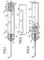
- Fig. 1is a partial longitudinal cross-sectional view of an apparatus for performing intraocular brachytherapy comprising a handpiece, a cannula secured to the handpiece, and a radiation source wire ("RSW") interior of the handpiece and cannula in a retracted position.
- RSWradiation source wire
- Fig. 2is a cross-sectional view of the apparatus of Fig. 1 with the radiation-emitting element advanced to the treatment position.
- Fig. 3is a top view (as compared to Figs. 1 and 2 ) of a portion of the housing comprising part of handpiece shown in Fig. 1 .
- Fig. 4is an enlarged view of the cannula associated with the system of Fig. 1 , in partial cross-section.
- Fig. 5is a fragmentary, cross-sectional view of the radioactive source wire forming a portion of the system shown in Fig. 1 .
- Fig. 6is a perspective view of the distal end of the cannula and a dose flattening filter comprising a portion of the tip or distal end of the cannula.
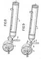
- Fig. 7is an exploded perspective view of a first embodiment of a positioning system for use with the system of Fig. 1 .
- Figs. 8 and 9illustrate the use of the positioning system of Fig. 7 in connection with the system of Fig. 1 .
- Fig. 10is an enlarged view showing the treatment of CNV with the device of Fig. 1 .
- Fig. 11shows the dose rate profile at the treatment side of the delivery device.
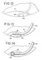
- Fig. 12is a schematic view of a further version of the cannula for use in the present invention having an inflatable balloon at its distal end.
- Fig. 13is a schematic view of an alternate embodiment of the cannula of Fig. 1 including retractable wires for properly spacing the treatment end of the cannula and the radioactive source from the target tissue.
- Fig. 14is a schematic view of an alternate version of the cannula in which a retractable wire basket is provided for maintaining the proper spacing of the radiation source with respect to the target tissue.
- Fig. 15is a schematic view of a further embodiment of the cannula for use with the present invention in which the cannula includes a lumen for injecting and withdrawing various fluids at the location of the distal end of the cannula.
- Fig. 16is a cross-sectional view of the cannula of Fig. 15 .
- Fig. 17is a schematic view of a further embodiment of the cannula for use in connection with the present invention in which the non-treatment side of the distal end of the catheter is relieved to minimize contact with the retina.
- vitreoretinal surgical techniquesare used to facilitate placement of a radioactive source that preferably, but not exclusively, emits beta or other ionizing radiation temporarily in a subretinal space by means of an intraocular cannula, sheath or probe.
- a radioactive sourcethat preferably, but not exclusively, emits beta or other ionizing radiation temporarily in a subretinal space by means of an intraocular cannula, sheath or probe.
- Other non-ionizing radiation sourcessuch as light or heat sources, as circumstances require, may also be used.
- an apparatusemploying the radioactive source and a delivery device that permits movement of the source between a stored position and treating position.
- the radiation sourceWhen in the stored (retracted) position, the radiation source is surrounded by a suitable material, such as a stainless steel and lead lining, that effectively protects the surgeon and patient during handling and initial positioning.
- the sourceis preferably located within a specially designed tip of platinum iridium (Pt/Ir), or other suitable material, that provides for directional administration of the radiation with controlled intensity, while shielding and protecting the retina and other surrounding non-target tissues.
- the systemincludes two main components: a radiation source, which may be located at the distal end of a source wire (RSW) 12 and a delivery device 14 that comprises, in the illustrated embodiment, a handle 16 and a delivery cannula 18 (also called a sheath or probe).
- a positioning system 20, shown in Fig. 7 , and method, illustrated in Figs. 8 and 9are provided to assist in the precise positioning of the device within the eye.
- Radiation sourceis broadly defined herein, and is not limited to ionizing radiation, light radiation, or heat radiation.
- the radiation sourceis intended to include a treatment source of any of a variety of treatment regimens, including ionizing radiation.
- the radiation source for the RSW 12comprises any suitable radiation source, including radioactive materials such as gamma and beta emitters, x-ray (e.g., miniaturized x-ray generators), and non-ionizing radiation sources, such as laser or other light sources.
- radioactive materialssuch as gamma and beta emitters
- x-raye.g., miniaturized x-ray generators
- non-ionizing radiation sourcessuch as laser or other light sources.
- ultrasound, heat, cryo-ablation, or microwave sourcesmay also be utilized.
- an essentially beta emitting materialsuch as a Strontium/Yttrium 90 (Sr-90/Y-90) beta emitting isotope is used.
- a source activityof approximately 11 mCi and a location of about 1-3 mm from the target tissue (preferably about 1-1.5 mm)
- the treatment durationis relatively short, approximately 2-4 minutes.
- the system and methodprovide for sub-retinal delivery of radiation at the site of the choroidal neovascularization that occurs in macular degeneration, or other treatment site.
- the systemWhen employing ionizing radiation, the system preferably provides radiation to a target site at a dose rate of from approximately 4 to 20 GY/min; with a preferred target dose of between approximately 10 and 40 GY, with the target dose more preferably being approximately 26 GY for neovascularized tissue.
- the preferred embodiment of the radiation sourceincludes a cylindrical aluminum insert 22 that is doped with the Sr-90/Y-90 isotope in accordance with conventional techniques and preferably resides inside a sealed stainless steel canister.
- the canistercomprises a seed tubing 24 sealed on its distal end with a lid 26 and on its proximal end with a lid 28.
- the stainless steel canistermay be mounted to a solid or braided wire made of stainless steel (or other material) to form the RSW 12 that is used to advance the source to and retract the source from the treatment location.
- the radioactive source wire 12preferably includes a relatively flexible distal or leading strand 30 and a relatively stiffer proximal or handle strand 32.
- the flexibility of the leading strand 30is such as to allow unimpeded mechanical transport through the cannula 18 around a radius of curvature of from 4 to 8 mm.
- the RSW 12has an overall length on the order of 190 mm, which provides a 10mm-15mm protrusion of the wire from the rear of the handle 16 (as seen in Figs. 1 and 2 ) when the RSW 12 is advanced to the treatment position, thus providing, for removal or repositioning of the RSW, if necessary.
- the distal end of the leading strand 30includes a connection tubing 34 closed by a lid 36 for facilitating attachment of the canister housing the radioactive insert 22.
- a further connection tubing 38is used to join the proximal and of the leading strand 30 to the distal end of the handle strand 32.
- the leading strand 30has a smaller outside diameter than the handle strand.
- the proximal end of the leading strand 30carries an additional length of tubing 40 to build up the outside diameter of the leading strand 30 to match that of the handle strand.
- the proximal end of the handle strand 32also includes a length of tubing 41 for reinforcement.
- the various components of the RSW 12are preferably made of stainless steel and are joined together by laser wielding.
- Other means for delivering and/or retrieving the radioactive source, as disclosed in the prior art,may also be used.
- the radioactive sourcemay not be secured to a wire, and movement of the source between treatment and storage positions can be accomplished pneumatically or hydraulically. See, e.g., U.S. Patent No. 5,683,345 .
- the delivery device 14is preferably, but not necessarily, handheld to facilitate control and positioning of the delivery cannula 18 during use.
- the radiation sourcee.g., a beta radiation source
- the handle 16includes a slider mechanism to which a proximal portion of the RSW 12 is secured, the slide mechanism being moveable between treatment position ( Fig. 2 ), in which the radioactive source 22 is positioned at the distal end of the cannula 18, and a retracted position ( Fig. 1 ) for storage of the radioactive source 22 within the handle 16,
- the radiation sourceis preferably shielded by a combination of stainless steel (inner shield) and lead (outer shield).
- the stainless steel shieldblocks the beta radiation, while the lead shield reduces the secondary radiation (known as brehmsstrahlung).
- Other suitable materialsmay also be used for shielding.
- the handle 16comprises a multi-part housing with an elongated cylindrical case 42 closed at its proximal end by end cap 44 and at its distal end by a central hub 46, to which the cannula 18 is secured.
- the hub 46is preferably made of stainless steel and serves as the inner radiation shield for the radioactive source when in the storage position.
- the wall thickness of the shielding portion of the hubis approximately 1.9 mm.
- the hub 46also carries the lead outer shield, designated 48, which has a wall thickness of approximately 4.6 mm.
- the hub 46 and outer shield 48are carried by a cup-like member 50 that is secured to the distal end of the case 42.
- the handle 16includes an advancement or positioning mechanism (also referred to as a slider mechanism), generally designated 52, for moving the radioactive source 22 between the storage and treatment positions.
- the slider mechanism 52includes a carrier member 54 that is slidingly received on the interior of the cylindrical case 42 of the handle 16.
- the carrier 54includes a central aperture, through which the handle strand 32 of the RSW 12 extends, with the RSW 12 being secured to the carrier 54 by means of a set screw 56.
- an actuator pin 58that extends through an elongated slot 60 in the case 42 is secured to the carrier 54.
- the slot 60lies in a plane defined by the curved cannula 18, thus having the same orientation as the cannula curve.
- the slot 60permits approximately 60 mm, or less, of travel for the carrier 54 and includes offsets 62, 64 at its distal and proximal ends, respectively, for receiving the actuator pin 58, thus providing positive visual and tactile indications of the radioactive source 22 being located in the treatment and storage positions.
- the proximal side of the carrier 54also includes a coil spring 66 secured thereto by screw 68 for biasing the actuator pin into a locked condition within proximal offset 64 when in the retracted position.
- the intraocular probe 18is preferably an integral part of the delivery device, and is fabricated of a rigid material, such as stainless steel.
- the probe, or cannula, in the illustrated embodiment,comprises a single lumen and is sealed at the distal end to prevent contact between the radiation source and the patient or the patient's bodily fluids.
- the distal end of the probeincludes an inner sleeve 70 (best seen in Fig. 6 ) in which the radiation source is located when in the treatment position.
- the inner sleeve 70is configured to provide a desired dose profile, which is discussed in greater detail below.
- the inner sleeve 70is received in a cover sleeve 72 that serves to seal the inner sleeve 70 and also provides some radiation attenuation.
- the distal end of the cannula 18is curved or bent at an angle to facilitate proper alignment of the radiation source and the treatment area.
- the tip 74 of the probe 18also preferably has a rounded wedge shape to facilitate positioning of the distal end under the retina, when the retina is partially detached and raised to form a "bleb" (as by injection of saline or other liquid under the retina) during the performance of the method.
- the treatment side of the tipincludes a molded, machined or otherwise formed window 76 (sealed by the cover sleeve 72) that allows for directional administration of radiation.
- the window 76is subdivided into four smaller windows by longitudinal and transverse splines 77 that intersect at centrally located solid area 79 that acts as a flattening filter to reduce the peak radiation from the source 22 received by tissue closest to the radiation source. As a result, the tissue to be irradiated at the treatment site receives a more uniform dosage.
- This flattening effectis shown in Fig. 11 , which plots the dose rate (in GY/min) as a function of radial and axial distance from the radiation source center. As can be seen in Fig.
- the peak dose rateis generally flat at the center of the source, and decreases essentially linearly as the distance from the center increases.
- the flattening filterpreferably comprises a shield of selected thickness and/or material suspended in the window at the point closest the treatment site that attenuates or blocks a portion of the radiation from escaping the probe.
- FIG. 7A first embodiment of a system 20 for precise positioning of the probe 16 is shown in Fig. 7 .
- the positioning system 20comprises a base 80 and contact extension 82 which serve as a reference member and are adapted to be mounted to the extra-ocular portion of the sheath or probe 18.
- a spring 84is located on the probe 18 to provide a positive engagement of the contact extension 82 (when carried on the base 80) against the sclera during initial placement. See Figs. 8 and 9 .
- the base. 80has a slot 86 sized to fit over the probe 18 so that it can be placed thereon.
- the contact extension 82also has a slot 88 thereon to facilitate placement on the probe 18 distally of the base 80.
- the contact extension 82is designed to seat on the base 80 and is maintained in position thereon by frictional engagement.
- a handle 90is provided that has a threaded end 92 that is received in a complimentarily-threaded aperture 94 in the base 80.
- the threaded end 92 of the handle 90serves as a set screw to secure the base 80 in position on the probe 18 after initial placement, as will be discussed in greater detail bellow.
- the positioning system 78may be made of any suitable material, but is preferably made of acetal.
- the probeis initially positioned, with the tip 74 of the probe in light contact with the target area to be irradiated, touching either the retina or the CNV tissue under the retina.
- the spring 84pushes the contact extension 82 mounted on the base 80 into contact with the sclera.
- the handle 90is then turned to engage against the probe 18, thus locking the base 80 into position on the probe 18.
- the probe 18is then withdrawn from the eye.
- a spacer 96which also has a slot 98 that permits it to be placed on the probe 18, is then placed between the base 80 and the contact extension 82, as seen in Fig. 9 , to accurately set the distance between the treatment area and the probe tip 74.
- the spacer 96has a thickness of from about 0.5 to 3 mm, and preferably 1-1.5 mm (more preferably 1 mm), so as to create a space of the same distance between the tip 74 of the probe 18 and the target area.
- the particular spacingmay vary with the eye disorder treated, the radiation source being used, and the size of the treatment area.
- a spacing of 1-2 mm (and preferably 1.5 mm)is the anticipated spacing for treating the neovascularized tissue associated with macular degeneration with a beta radiation source as described earlier.
- the contact extensionrests against the sclera, resisting or preventing further axial movement of the delivery device into the eye.
- positioning of the probe tipcan be facilitated by the use of intra-ocular ultrasound or doppler measurement of the distances between the distal end of the cannula and the target tissue.
- the distal end of the cannulamay include an ultrasound or doppler transducer (communicating with a read-out device) to both transmit and receive ultrasound or doppler waves.
- the data generated therebyis analyzed in real time, and a calculated measurement of the distance is presented on an optical readout or indicator.
- optical interferometry devices and techniquescan be employed for measuring the distance between the cannula tip and the target tissue.
- the tip of the probe 18may include one or more balloons 100 that are inflatable upon locating the probe tip under the retina (R) in the bleb to insure for spacing of the probe tip between the retina and treatment zone.
- the distal end 101 of the probe 18can be at an angle with respect to the axis of the probe where the radioactive source is located when in the treatment position (again shown in Fig. 12 - see also Fig. 15 and 17 ). The angled distal end 101 insures that a predetermined minimum distance is maintained between the radioactive source and the target tissue.
- a preformed wire, or series of wires 102are extendable from a lumen 104 in the probe to properly space or bump-off the probe tip from the treatment zone when advanced out of the lumen.
- a further alternative, shown in Fig. 14is to use a retractable wire basket 106 that is advanced through a lumen 104 in the probe when the probe is placed at the treatment site.
- a still further alternativeis to secure a optic fiber to the probe that extends beyond the distal end an amount corresponding to the desired spacing. When the optic fiber contacts the target tissue, the fiber darkens, thus alerting the surgeon to the desired spacing.
- the basic procedure for sub-retinal intraocular brachytherapyis accomplished through standard vitrectomy and retinal detachment techniques, with the basic steps as follows.
- the surgeonconfirms the location of the target tissue using retinal vascular landmarks and identifies the preferred location of the sclerotomy entry point (i.e., temporal, nasal, etc.) in order to limit exposure of the fovea during treatment.
- the surgeonwill also want to confirm that the radiation source is properly positioned in the probe, when advanced to the treatment position.
- the subjectis prepared pursuant to standard vitrectomy procedures. Specifically, the pupil of the subject is dilated and the patient is positioned ventrally on the operating table. After appropriate cardiac and respiratory monitoring is established, and appropriate anesthesia is induced, the eye is anesthetized, such as with a retrobulbar or peribulbar anesthesia.
- a speculumis placed to secure the eye lid, and surgery begins with a conjunctival incision into the superotemporal, superonasal and inferotemporal quadrants of the eye to be treated.
- a scleral incisionis made approximately 3 to 4 mm away from the surgical limbus in the inferotemporal quadrant, and an infusion cannula is inserted into the vitreous cavity.
- the infusion lineis opened and a second and third scleratomy are created 3 to 4 mm away from the surgical limbus in locations determined prior to commencement of the surgery in the superonasal quadrant.
- An appropriate lens for vitreoretinal surgeryis positioned and a vitrectomy performed, a standard endoilluminator being used to illuminate the vitreous cavity.
- the treatment probeis positioned.
- the spring 84 of the positioning system 20is carefully slid over the probe 18 up to the device handle 16, and the positioning system is placed on to the probe shaft without the spacer element 96. See Fig. 8 , The sclerotomy is extended to a length of approximately 1.3 mm, and the delivery probe is inserted through the sclerotomy incision into the vitreous cavity.
- the surgeonplaces the tip of the probe directly above the macula. Specifically, the probe is positioned by gently touching the retinal tissue, while directly holding the probe center marker (a mark on the probe tip designating the center of the radiation source) above the center of the CNV complex. While the surgeon holds the probe steady at this position, the positioning system (base 80 and contact extension 82) without the spacer 96 is secured onto the external portion of the delivery probe while in contact with the sclera to identify the precise location of the probe as it contacts the retina by tightening the handle, and the cannula is removed from the vitreous cavity. The spacer 96 is then placed between the positioning system base 80 and the contact extension 82, as shown in Fig. 9 .
- a localized retinal detachment(the "bleb") is created by using a sub-retinal infusion needle in the macular region, the bleb including the area of choroidal neovascularization.
- a new retinotomyis created on the temporal edge of the bleb, with the new incision created less than 4 mm away from the fovea to reduce the risk of a peripheral retinal tear.
- the retinotomyis approximately 1.3 mm in diameter in order to accommodate the probe.
- the delivery device probe 18is then reinserted into the vitreous cavity and into the sub-retinal space through the second retinotomy, as seen in Fig. 10 .
- the distal end of the probeis positioned directly above the center of the CNV complex with the positioning system touching the sclera, thus insuring the distance of the probe tip is about 1.5 mm above the target area.
- the radiation doseis delivered to the target tissue.
- the radiation sourceis advanced by pushing the slider mechanism towards the tip of the probe. Once advanced, the source wire is locked into position by locating the pin in the detent 62. After the appropriate treatment time, the slider mechanism is retracted to bring the radioactive source back to the storage and locked position. After insuring that the radioactive source has been fully retracted into its storage position, the delivery probe is removed from the bleb and withdrawn from the eye.
- the retinaAfter removal of the probe, the retina is then reattached intraoperatively, and a compete fluid-air exchange is performed, resulting in an air or gas tamponade in the vitreous cavity.
- the retinotomyis closed by, e.g., laser photocoagulation, if necessary, while the superior sclerotomy is closed with ophthalmic sutures.
- the inferotemporal sclerotomyis closed, and the conjunctiva is sutured with appropriate ophthalmic sutures.
- a mixture of antibiotics and steroidsmay then be administered in the sub-conjuetival space.
- the retina and other non-target tissue during treatmentmay be shielded and protected by introducing a radiation-attenuating fluid into the bleb that is created by lifting the retina away from the CNV.
- the fluidcan consist of saline, or a fluid with higher attenuation coefficient, such as contrast media.
- the use of a radiation-attenuating fluid to protect non-target tissuemay also be advantageous during epi-retinal and epi-scleral applications of radiation. In such cases, the radiation-attenuating fluid is merely introduced into the interior of the eye, rather than into the sub-retinal space.
- the bleb shapemay be maintained in several different ways.
- the bleb shapemay be maintained by injecting a high viscosity material into the sub-retinal space created by the bleb. Because of the material's high viscosity, its ability to flow through the retinotomy is reduced. The high viscosity material is removed, after treatment, using a standard vitrectomy device.
- a high density materialis a podium hyaluronate preparation for ophthalmic use sold by Pharmacia Company, under the trademark HEALON®.
- a substance with variable viscosity having a high initial viscosity during the treatment time, with a lower viscosity thereafter,would further facilitate the removal of the material form the sub-retinal space upon completion of the procedure.
- a sealing substancesuch as HEALON ®
- An inflation agentsuch as saline
- salinecan also be continuously introduced into the sub-retinal space with a small positive pressure by means of an open lumen 108 associated with the cannula 18 ( Figs. 15, 16 ).
- the distal end of the cannulacan be provided with a balloon ( Fig. 12 ) that is inflated after the distal end of the cannula is introduced into the bleb in order to support the bleb and prevent the bleb from deflating or collapsing.
- the potential for damage to the photoreceptors by the probemay also be minimized if the cannula has a low-friction surface.
- Thiscan be provided by coating the probe with a lubricant or other coating, such as Teflon or electrolytic carbon, or providing the cannula with a highly-polished surface, as by electro-polishing.
- the backside 110 of the probei.e., the non-treatment side
- can be relieved, as shown in Fig. 17to lessen the degree of contact of the probe with the photoreceptors.
- the area of the incision resulting from the vitrectomy performed to create the blebmay be cauterized to prevent or limit retinal bleeding.
- Such cauterizationmay be achieved by diathermy, cryopexy, or the application of laser or RF energy using instrumentation and methods known for re-attaching the retina to the retinal pigment epithelium in the case of retinal detachment.
- blood coagulantssuch as antihemophilic Factor VIII (recombinant) (available from Bayer Healthcare as Kogenate), aminocaproic acid (available form Immunex as Amicar), and desmopressin acetate (available from Rhone Poulanc Rorer as Octostim), may also be injected into the sub-retinal space to limit bleeding by means of the separate lumen associated with the treatment device, as shown in Figs. 15, 16 .
- the coagulantmay also be removed through the same lumen.
- Injection of an iron-binding substance (such as apotransferrin) into the bloodmay also be used in facilitating the removal of blood from the sub-retinal space and preventing its oxidation.
- an anti-proliferating drug(anti-Vascular Endothelial Growth Factor or anti-VEGF agent, such as pegaptanib sodium) may be injected into the sub-retinal space to prevent and/or limit further growth of the CNV.
- anti-proliferating druganti-Vascular Endothelial Growth Factor or anti-VEGF agent, such as pegaptanib sodium
- the tip of the probeinclude an inflatable balloon that causes pressure on the retina when inflated to reduce the blood flow thereto, the radiation treatment being performed through the balloon.
- a deployable maskmade of a radiation-blocking material that will be deployed and located over the non-target tissue, while leaving the target tissue exposed.
- a materialcould be carried by the tip of probe 18 or by a separate device and deployed after formation of the bleb. The material could be biodegradable if desired.
- the delivery device of the present inventionmay also be used in methods for intraocular, epi-retinal application of radiation, in which no bleb is created.
- Performance of the epi-retinal methodis substantially easier then the sub-retinal approach.
- Intraocular accessmade simply through a sclerotomy, and the distal end of the probe is located over the macula. No detachment of the retina or the creation of a bleb is required.
- Accurate placement of the probemay be accomplished by any of the positioning systems described. Ultrasound or Doppler techniques known in the art may also be used. Other mechanical methods may also be used, such as putting a stand-off fiber or "whisker" on the tip of the probe that touches the retina when the probe is properly positioned.
- an inflatable balloonthat, when inflated, spaces the probe the desired distance from the target tissue can also be used.
- a miniature radiation sensorthat can be remotely interrogated may be placed on the retinal surface, and the distance between the probe tip and the surface of the retina can be determined based upon the level of radiation measured by the sensor. If multiple (i.e. 3) sensors are used, triangulation of the measured radiation intensity would provide an accurate measurement of position. If at least three miniature event counters or sensors are positioned in an array on the periphery of the retina equidistant from the target tissue, the intensity/frequency of events measured by each point can be analyzed and then compared. The position of source then can be determined through well-known three-dimensional triangulation calculations at the beginning of the radiation administration.
- the event counters/sensorscan be placed either in the eye; behind the eye, or even on the front surface of the eye, if the radiation source produced a sufficient emission to be measured externally.
- the radiation sourcecan carry a small transducer on its tip that would emit a "ping" that can be picked up by receivers positioned as described above.
- Other signaling/receiving systemssuch as light or RF can also be used.
- a permanent magnet disposed on the tip of the devicecould produce a sufficient Galvanic effect in appropriate sensors to be measurable, especially in an epi-retinal application where the size constraints of the device are less critical. A digitally-enclosed signal would provide improved speed and accuracy.
Landscapes
- Health & Medical Sciences (AREA)
- Biomedical Technology (AREA)
- Engineering & Computer Science (AREA)
- Radiology & Medical Imaging (AREA)
- Pathology (AREA)
- Nuclear Medicine, Radiotherapy & Molecular Imaging (AREA)
- Ophthalmology & Optometry (AREA)
- Life Sciences & Earth Sciences (AREA)
- Animal Behavior & Ethology (AREA)
- General Health & Medical Sciences (AREA)
- Public Health (AREA)
- Veterinary Medicine (AREA)
- Radiation-Therapy Devices (AREA)
- Surgical Instruments (AREA)
- Medicines Containing Material From Animals Or Micro-Organisms (AREA)
Abstract
Description
- The present invention relates to apparatus and systems for performing intraocular brachytherapy. The invention may be employed in the treatment of a variety of eye disorders, but is particularly suited for treatment of macular degeneration in which neovascularized ocular tissue is treated by means of a local, directional delivery of a radiation dose emitted by a radioactive source to target tissues.
- The slow, progressive loss of central vision is known as macular degeneration. Macular degeneration affects the macula, a small portion of the retina. The retina is a fine layer of light-sensing nerve cells that covers the inside back portion of the eye. The macula is the central, posterior part of the retina and contains the largest concentration of photoreceptors. The macula is typically 5 to 6 mm in diameter, and its central portion is known as the fovea. While all parts of the retina contribute to sight, the macula provides the sharp, central vision that is requited to see objects clearly and for daily activities including reading and driving.
- Macular degeneration is generally caused by age (termed Age Related Macular Degeneration or "AMD") or poor circulation in the eyes. Smokers and individuals with circulatory problems have an increased risk for developing the condition. AMD is the leading cause of blindness in people older than 50 years in developed countries. Between the ages of 52-64, approximately 2% of the population are effected. This rises to an astounding 28% of the population over the age of 75.
- There are two forms of macular degeneration, which are known as "wet" and "dry" macular degeneration. Dry macular degeneration blurs the central vision slowly over time. Individuals with this form of macular degeneration may experience a dimming or distortion of vision that is particularly noticeable when trying to read. In dry macular degeneration, yellowish deposits called drusen develop beneath the macula. Drusen are accumulations of fatty deposits, and most individuals older than 50 years have at least one small druse. These fatty deposits are usually carried away by blood vessels that transport nutrients to the retina. However, this process is diminished in macular degeneration and the deposits build up. Dry macular degeneration may also result when the layer of light-sensitive cells in the macula become thinner as cells break down over time. Generally, a person with the dry form of macular degeneration in one eye eventually develops visual problems in both eyes. However, dry macular degeneration rarely causes total loss of reading vision.
- Wet macular degeneration (which is the neovascular form of the disease) is more severe than dry macular degeneration. The loss of vision due to wet macular degeneration also comes much more quickly than dry macular degeneration. In this form of the disease, unwanted new blood vessels grow beneath the macula (Choroidal Neo-Vascularization (CNV) endothelial cells). These choroidal blood vessels are fragile and leak fluid and blood, which causes separation of tissues and damages light sensitive cells in the retina. Individuals with this form of macular degeneration typically experience noticeable distortion of vision such as, for example, seeing straight lines as wavy, and seeing blank spots in their field of vision.
- Early diagnosis of the wet form of macular degeneration is vital. If the leakage and bleeding from the choroidal blood vessels is allowed to continue, much of the nerve tissue in the macula may be killed or damaged. Such damage cannot be repaired because the nerve cells of the macula do not grow back once they have been destroyed. While wet AMD comprises only about 20% of the total AMD cases, it is responsible for approximately 90% of vision loss attributable to AMD.
- It has been proposed to provide a device that is particularly suitable for the localized delivery of radiation for the treatment of macular degeneration. See, U.S. Pub. Appln.
US 2002/0115902A1 to DeJuan, et al .
A localized retinal detachment (called a "bleb") is created by performing a retinotomy and injecting saline therethrough using a subretinal infusion needle, thus creasing a space between the partially-detached retina and the area of chloridal neo-Vascularization. A radiation-emitting source is introduced into the bleb and the CNV is directly irradiated. The exposure of the new blood vessels formed during the wet form of macula degeneration to radiation provides sufficient disruption of the cellular structures of the new blood cell lesions to reverse, prevent, or minimize the progression of the macular degeneration disease process. Such therapy can potentially restore visual acuity, extend retention of visual acuity or slow the progressive loss of visual acuity.US 2002 10115902 A1 US-6,443,881 discloses an ophthalmic brachytherapy device having a radiation applicator that is designed to contact the eye ball. [0008] The present application relates to advances in apparatus, systems and methods for performing intraocular brachytherapy, in general, and for the treatment of macular degeneration with radiation, in particular.Fig. 1 is a partial longitudinal cross-sectional view of an apparatus for performing intraocular brachytherapy comprising a handpiece, a cannula secured to the handpiece, and a radiation source wire ("RSW") interior of the handpiece and cannula in a retracted position.Fig. 2 is a cross-sectional view of the apparatus ofFig. 1 with the radiation-emitting element advanced to the treatment position.Fig. 3 is a top view (as compared toFigs. 1 and 2 ) of a portion of the housing comprising part of handpiece shown inFig. 1 .Fig. 4 is an enlarged view of the cannula associated with the system ofFig. 1 , in partial cross-section.Fig. 5 is a fragmentary, cross-sectional view of the radioactive source wire forming a portion of the system shown inFig. 1 .Fig. 6 is a perspective view of the distal end of the cannula and a dose flattening filter comprising a portion of the tip or distal end of the cannula.Fig. 7 is an exploded perspective view of a first embodiment of a positioning system for use with the system ofFig. 1 .Figs. 8 and 9 illustrate the use of the positioning system ofFig. 7 in connection with the system ofFig. 1 .Fig. 10 is an enlarged view showing the treatment of CNV with the device ofFig. 1 .Fig. 11 shows the dose rate profile at the treatment side of the delivery device.Fig. 12 is a schematic view of a further version of the cannula for use in the present invention having an inflatable balloon at its distal end.Fig. 13 is a schematic view of an alternate embodiment of the cannula ofFig. 1 including retractable wires for properly spacing the treatment end of the cannula and the radioactive source from the target tissue.Fig. 14 is a schematic view of an alternate version of the cannula in which a retractable wire basket is provided for maintaining the proper spacing of the radiation source with respect to the target tissue.Fig. 15 is a schematic view of a further embodiment of the cannula for use with the present invention in which the cannula includes a lumen for injecting and withdrawing various fluids at the location of the distal end of the cannula.Fig. 16 is a cross-sectional view of the cannula ofFig. 15 .Fig. 17 is a schematic view of a further embodiment of the cannula for use in connection with the present invention in which the non-treatment side of the distal end of the catheter is relieved to minimize contact with the retina.- In the sub-retinal treatment of AMD, vitreoretinal surgical techniques are used to facilitate placement of a radioactive source that preferably, but not exclusively, emits beta or other ionizing radiation temporarily in a subretinal space by means of an intraocular cannula, sheath or probe. Other non-ionizing radiation sources, such as light or heat sources, as circumstances require, may also be used.
- In accordance with one aspect of the present invention, an apparatus is provided employing the radioactive source and a delivery device that permits movement of the source between a stored position and treating position. When in the stored (retracted) position, the radiation source is surrounded by a suitable material, such as a stainless steel and lead lining, that effectively protects the surgeon and patient during handling and initial positioning. During treatment, the source is preferably located within a specially designed tip of platinum iridium (Pt/Ir), or other suitable material, that provides for directional administration of the radiation with controlled intensity, while shielding and protecting the retina and other surrounding non-target tissues.
- With reference to
Figs. 1 and 2 , the system, generally designated 10, includes two main components: a radiation source, which may be located at the distal end of a source wire (RSW) 12 and adelivery device 14 that comprises, in the illustrated embodiment, ahandle 16 and a delivery cannula 18 (also called a sheath or probe). In addition, apositioning system 20, shown inFig. 7 , and method, illustrated inFigs. 8 and 9 , are provided to assist in the precise positioning of the device within the eye. - Radiation source is broadly defined herein, and is not limited to ionizing radiation, light radiation, or heat radiation. For example, the radiation source is intended to include a treatment source of any of a variety of treatment regimens, including ionizing radiation. The radiation source for the
RSW 12 comprises any suitable radiation source, including radioactive materials such as gamma and beta emitters, x-ray (e.g., miniaturized x-ray generators), and non-ionizing radiation sources, such as laser or other light sources. Alternatively, ultrasound, heat, cryo-ablation, or microwave sources may also be utilized. - Preferably, an essentially beta emitting material, such as a Strontium/Yttrium 90 (Sr-90/Y-90) beta emitting isotope is used. With a source activity of approximately 11 mCi and a location of about 1-3 mm from the target tissue (preferably about 1-1.5 mm), the treatment duration is relatively short, approximately 2-4 minutes. The system and method provide for sub-retinal delivery of radiation at the site of the choroidal neovascularization that occurs in macular degeneration, or other treatment site. When employing ionizing radiation, the system preferably provides radiation to a target site at a dose rate of from approximately 4 to 20 GY/min; with a preferred target dose of between approximately 10 and 40 GY, with the target dose more preferably being approximately 26 GY for neovascularized tissue.
- As illustrated in
Fig. 5 , the preferred embodiment of the radiation source includes acylindrical aluminum insert 22 that is doped with the Sr-90/Y-90 isotope in accordance with conventional techniques and preferably resides inside a sealed stainless steel canister. The canister comprises a seed tubing 24 sealed on its distal end with alid 26 and on its proximal end with a lid 28. The stainless steel canister may be mounted to a solid or braided wire made of stainless steel (or other material) to form theRSW 12 that is used to advance the source to and retract the source from the treatment location. - As shown in
Fig. 5 , theradioactive source wire 12 preferably includes a relatively flexible distal or leadingstrand 30 and a relatively stiffer proximal or handlestrand 32. Specifically, the flexibility of the leadingstrand 30 is such as to allow unimpeded mechanical transport through thecannula 18 around a radius of curvature of from 4 to 8 mm. TheRSW 12 has an overall length on the order of 190 mm, which provides a 10mm-15mm protrusion of the wire from the rear of the handle 16 (as seen inFigs. 1 and 2 ) when theRSW 12 is advanced to the treatment position, thus providing, for removal or repositioning of the RSW, if necessary. - The distal end of the leading
strand 30 includes aconnection tubing 34 closed by alid 36 for facilitating attachment of the canister housing theradioactive insert 22. Afurther connection tubing 38 is used to join the proximal and of the leadingstrand 30 to the distal end of thehandle strand 32. In the illustrated embodiment, the leadingstrand 30 has a smaller outside diameter than the handle strand. Thus, the proximal end of the leadingstrand 30 carries an additional length oftubing 40 to build up the outside diameter of the leadingstrand 30 to match that of the handle strand. The proximal end of thehandle strand 32 also includes a length oftubing 41 for reinforcement. Other than theradioactive insert 22, the various components of theRSW 12 are preferably made of stainless steel and are joined together by laser wielding. Other means for delivering and/or retrieving the radioactive source, as disclosed in the prior art, may also be used. For example, the radioactive source may not be secured to a wire, and movement of the source between treatment and storage positions can be accomplished pneumatically or hydraulically. See, e.g.,U.S. Patent No. 5,683,345 . - The
delivery device 14 is preferably, but not necessarily, handheld to facilitate control and positioning of thedelivery cannula 18 during use. When not in use, theradiation source 22, e.g., a beta radiation source, may be positioned inside the shieldedstorage handle 16. Thehandle 16 includes a slider mechanism to which a proximal portion of theRSW 12 is secured, the slide mechanism being moveable between treatment position (Fig. 2 ), in which theradioactive source 22 is positioned at the distal end of thecannula 18, and a retracted position (Fig. 1 ) for storage of theradioactive source 22 within thehandle 16, While in the storage position, the radiation source is preferably shielded by a combination of stainless steel (inner shield) and lead (outer shield). The stainless steel shield blocks the beta radiation, while the lead shield reduces the secondary radiation (known as brehmsstrahlung). Other suitable materials may also be used for shielding. - With reference to
Figs. 1-3 , thehandle 16 comprises a multi-part housing with an elongatedcylindrical case 42 closed at its proximal end byend cap 44 and at its distal end by acentral hub 46, to which thecannula 18 is secured. Thehub 46 is preferably made of stainless steel and serves as the inner radiation shield for the radioactive source when in the storage position. The wall thickness of the shielding portion of the hub is approximately 1.9 mm. Thehub 46 also carries the lead outer shield, designated 48, which has a wall thickness of approximately 4.6 mm. Thehub 46 andouter shield 48 are carried by a cup-like member 50 that is secured to the distal end of thecase 42. - As noted above, the
handle 16 includes an advancement or positioning mechanism (also referred to as a slider mechanism), generally designated 52, for moving theradioactive source 22 between the storage and treatment positions. Theslider mechanism 52 includes acarrier member 54 that is slidingly received on the interior of thecylindrical case 42 of thehandle 16. Thecarrier 54 includes a central aperture, through which thehandle strand 32 of theRSW 12 extends, with theRSW 12 being secured to thecarrier 54 by means of aset screw 56. - For moving the
carrier 54 between the proximal and distal ends of thecase 42, anactuator pin 58 that extends through anelongated slot 60 in thecase 42 is secured to thecarrier 54. As illustrated, theslot 60 lies in a plane defined by thecurved cannula 18, thus having the same orientation as the cannula curve. Theslot 60 permits approximately 60 mm, or less, of travel for thecarrier 54 and includesoffsets actuator pin 58, thus providing positive visual and tactile indications of theradioactive source 22 being located in the treatment and storage positions. The proximal side of thecarrier 54 also includes acoil spring 66 secured thereto byscrew 68 for biasing the actuator pin into a locked condition within proximal offset 64 when in the retracted position. - With reference to
Fig. 4 , theintraocular probe 18 is preferably an integral part of the delivery device, and is fabricated of a rigid material, such as stainless steel. The probe, or cannula, in the illustrated embodiment, comprises a single lumen and is sealed at the distal end to prevent contact between the radiation source and the patient or the patient's bodily fluids. More particularly, the distal end of the probe includes an inner sleeve 70 (best seen inFig. 6 ) in which the radiation source is located when in the treatment position. Theinner sleeve 70 is configured to provide a desired dose profile, which is discussed in greater detail below. Theinner sleeve 70 is received in acover sleeve 72 that serves to seal theinner sleeve 70 and also provides some radiation attenuation. - The distal end of the
cannula 18 is curved or bent at an angle to facilitate proper alignment of the radiation source and the treatment area. Thetip 74 of theprobe 18 also preferably has a rounded wedge shape to facilitate positioning of the distal end under the retina, when the retina is partially detached and raised to form a "bleb" (as by injection of saline or other liquid under the retina) during the performance of the method. - The treatment side of the tip includes a molded, machined or otherwise formed window 76 (sealed by the cover sleeve 72) that allows for directional administration of radiation. The
window 76 is subdivided into four smaller windows by longitudinal andtransverse splines 77 that intersect at centrally locatedsolid area 79 that acts as a flattening filter to reduce the peak radiation from thesource 22 received by tissue closest to the radiation source. As a result, the tissue to be irradiated at the treatment site receives a more uniform dosage. This flattening effect is shown inFig. 11 , which plots the dose rate (in GY/min) as a function of radial and axial distance from the radiation source center. As can be seen inFig. 11 , the peak dose rate is generally flat at the center of the source, and decreases essentially linearly as the distance from the center increases. Various structures of the flattening filter are discussed in the co-pending PCT application "Radioactive Radiation Source for Ophthalmic Brachytherapy,"PCT/EP2004/012415, filed November 3, 2004 - A first embodiment of a
system 20 for precise positioning of theprobe 16 is shown inFig. 7 . Thepositioning system 20 comprises abase 80 andcontact extension 82 which serve as a reference member and are adapted to be mounted to the extra-ocular portion of the sheath orprobe 18. Using the sclera (the surface of the eye) as a dimensional reference point or surface, aspring 84 is located on theprobe 18 to provide a positive engagement of the contact extension 82 (when carried on the base 80) against the sclera during initial placement. SeeFigs. 8 and 9 . - For purposes of assembly onto the probe, the base. 80 has a
slot 86 sized to fit over theprobe 18 so that it can be placed thereon. Thecontact extension 82 also has aslot 88 thereon to facilitate placement on theprobe 18 distally of thebase 80. Thecontact extension 82 is designed to seat on thebase 80 and is maintained in position thereon by frictional engagement. Ahandle 90 is provided that has a threadedend 92 that is received in a complimentarily-threadedaperture 94 in thebase 80. The threadedend 92 of thehandle 90 serves as a set screw to secure the base 80 in position on theprobe 18 after initial placement, as will be discussed in greater detail bellow. The positioning system 78 may be made of any suitable material, but is preferably made of acetal. - With reference to
Fig. 8 , the probe is initially positioned, with thetip 74 of the probe in light contact with the target area to be irradiated, touching either the retina or the CNV tissue under the retina. Thespring 84 pushes thecontact extension 82 mounted on the base 80 into contact with the sclera. Thehandle 90 is then turned to engage against theprobe 18, thus locking the base 80 into position on theprobe 18. Theprobe 18 is then withdrawn from the eye. With the base 80 locked in position on the probe, aspacer 96, which also has aslot 98 that permits it to be placed on theprobe 18, is then placed between the base 80 and thecontact extension 82, as seen inFig. 9 , to accurately set the distance between the treatment area and theprobe tip 74. - In practice, the
spacer 96 has a thickness of from about 0.5 to 3 mm, and preferably 1-1.5 mm (more preferably 1 mm), so as to create a space of the same distance between thetip 74 of theprobe 18 and the target area. The particular spacing may vary with the eye disorder treated, the radiation source being used, and the size of the treatment area. A spacing of 1-2 mm (and preferably 1.5 mm) is the anticipated spacing for treating the neovascularized tissue associated with macular degeneration with a beta radiation source as described earlier. During the radiation delivery, the contact extension rests against the sclera, resisting or preventing further axial movement of the delivery device into the eye. - Alternatively, positioning of the probe tip can be facilitated by the use of intra-ocular ultrasound or doppler measurement of the distances between the distal end of the cannula and the target tissue. In such cases, the distal end of the cannula may include an ultrasound or doppler transducer (communicating with a read-out device) to both transmit and receive ultrasound or doppler waves. The data generated thereby is analyzed in real time, and a calculated measurement of the distance is presented on an optical readout or indicator. In a similar manner, optical interferometry devices and techniques can be employed for measuring the distance between the cannula tip and the target tissue.
- Structures for assuring the proper spacing of the probe tip from the target site can take other forms. For example, as shown in
Fig. 12 , the tip of theprobe 18 may include one ormore balloons 100 that are inflatable upon locating the probe tip under the retina (R) in the bleb to insure for spacing of the probe tip between the retina and treatment zone. In addition, or alternatively, thedistal end 101 of theprobe 18 can be at an angle with respect to the axis of the probe where the radioactive source is located when in the treatment position (again shown inFig. 12 - see alsoFig. 15 and 17 ). The angleddistal end 101 insures that a predetermined minimum distance is maintained between the radioactive source and the target tissue. - In a second alternative, shown in
Fig. 13 , a preformed wire, or series ofwires 102, are extendable from alumen 104 in the probe to properly space or bump-off the probe tip from the treatment zone when advanced out of the lumen. A further alternative, shown inFig. 14 , is to use aretractable wire basket 106 that is advanced through alumen 104 in the probe when the probe is placed at the treatment site. A still further alternative is to secure a optic fiber to the probe that extends beyond the distal end an amount corresponding to the desired spacing. When the optic fiber contacts the target tissue, the fiber darkens, thus alerting the surgeon to the desired spacing. - The basic procedure for sub-retinal intraocular brachytherapy according to the present invention is accomplished through standard vitrectomy and retinal detachment techniques, with the basic steps as follows. Prior to treatment, the surgeon confirms the location of the target tissue using retinal vascular landmarks and identifies the preferred location of the sclerotomy entry point (i.e., temporal, nasal, etc.) in order to limit exposure of the fovea during treatment. The surgeon will also want to confirm that the radiation source is properly positioned in the probe, when advanced to the treatment position. A device for testing for the proper positioning of the radiation source, and the method of its use, is disclosed in the co-pending PCT application, "Test Devise for Testing positioning of a Radioactive Source and Method of Using Same,"
PCT/EP2004/012416, filed November 3, 2004 - Then the subject is prepared pursuant to standard vitrectomy procedures. Specifically, the pupil of the subject is dilated and the patient is positioned ventrally on the operating table. After appropriate cardiac and respiratory monitoring is established, and appropriate anesthesia is induced, the eye is anesthetized, such as with a retrobulbar or peribulbar anesthesia.
- Next, the treatment area is accessed. A speculum is placed to secure the eye lid, and surgery begins with a conjunctival incision into the superotemporal, superonasal and inferotemporal quadrants of the eye to be treated.. A scleral incision is made approximately 3 to 4 mm away from the surgical limbus in the inferotemporal quadrant, and an infusion cannula is inserted into the vitreous cavity. After confirming that the infusion cannula is positioned properly, the infusion line is opened and a second and third scleratomy are created 3 to 4 mm away from the surgical limbus in locations determined prior to commencement of the surgery in the superonasal quadrant. An appropriate lens for vitreoretinal surgery is positioned and a vitrectomy performed, a standard endoilluminator being used to illuminate the vitreous cavity.
- Next, the treatment probe is positioned. To this end, the
spring 84 of thepositioning system 20 is carefully slid over theprobe 18 up to thedevice handle 16, and the positioning system is placed on to the probe shaft without thespacer element 96. SeeFig. 8 , The sclerotomy is extended to a length of approximately 1.3 mm, and the delivery probe is inserted through the sclerotomy incision into the vitreous cavity. - Under microscopic visualization, the surgeon places the tip of the probe directly above the macula. Specifically, the probe is positioned by gently touching the retinal tissue, while directly holding the probe center marker (a mark on the probe tip designating the center of the radiation source) above the center of the CNV complex. While the surgeon holds the probe steady at this position, the positioning system (
base 80 and contact extension 82) without thespacer 96 is secured onto the external portion of the delivery probe while in contact with the sclera to identify the precise location of the probe as it contacts the retina by tightening the handle, and the cannula is removed from the vitreous cavity. Thespacer 96 is then placed between thepositioning system base 80 and thecontact extension 82, as shown inFig. 9 . - A localized retinal detachment (the "bleb") is created by using a sub-retinal infusion needle in the macular region, the bleb including the area of choroidal neovascularization. A new retinotomy is created on the temporal edge of the bleb, with the new incision created less than 4 mm away from the fovea to reduce the risk of a peripheral retinal tear. The retinotomy is approximately 1.3 mm in diameter in order to accommodate the probe. The
delivery device probe 18 is then reinserted into the vitreous cavity and into the sub-retinal space through the second retinotomy, as seen inFig. 10 . The distal end of the probe is positioned directly above the center of the CNV complex with the positioning system touching the sclera, thus insuring the distance of the probe tip is about 1.5 mm above the target area. - Next, the radiation dose is delivered to the target tissue. To this end, the radiation source is advanced by pushing the slider mechanism towards the tip of the probe. Once advanced, the source wire is locked into position by locating the pin in the
detent 62. After the appropriate treatment time, the slider mechanism is retracted to bring the radioactive source back to the storage and locked position. After insuring that the radioactive source has been fully retracted into its storage position, the delivery probe is removed from the bleb and withdrawn from the eye. - After removal of the probe, the retina is then reattached intraoperatively, and a compete fluid-air exchange is performed, resulting in an air or gas tamponade in the vitreous cavity. The retinotomy is closed by, e.g., laser photocoagulation, if necessary, while the superior sclerotomy is closed with ophthalmic sutures. The inferotemporal sclerotomy is closed, and the conjunctiva is sutured with appropriate ophthalmic sutures. A mixture of antibiotics and steroids may then be administered in the sub-conjuetival space.
- In an alternate method, the retina and other non-target tissue during treatment may be shielded and protected by introducing a radiation-attenuating fluid into the bleb that is created by lifting the retina away from the CNV. The fluid can consist of saline, or a fluid with higher attenuation coefficient, such as contrast media. The use of a radiation-attenuating fluid to protect non-target tissue may also be advantageous during epi-retinal and epi-scleral applications of radiation. In such cases, the radiation-attenuating fluid is merely introduced into the interior of the eye, rather than into the sub-retinal space.
- Maintaining the bleb shape during the course of the procedure is also important to minimising the potential for damage to the photoreceptors. It is contemplated that the bleb shape may be maintained in several different ways. For example, the bleb shape may be maintained by injecting a high viscosity material into the sub-retinal space created by the bleb. Because of the material's high viscosity, its ability to flow through the retinotomy is reduced. The high viscosity material is removed, after treatment, using a standard vitrectomy device. One suitable high density material is a podium hyaluronate preparation for ophthalmic use sold by Pharmacia Company, under the trademark HEALON®. A substance with variable viscosity having a high initial viscosity during the treatment time, with a lower viscosity thereafter, would further facilitate the removal of the material form the sub-retinal space upon completion of the procedure. A gelatinous substance whose viscosity can be reduced through the administration of a diluting agent (e.g., water), a chemical agent (for adjusting ph), a temperature-charging agent or energy, photo reaction due to light administration, etc., would be suitable.
- Other methods for maintaining the bleb shape include applying a sealing substance (such as HEALON®) to the retinotomy and the probe/cannula inserted therethrough to prevent the bleb from deflating by blocking the escape of fluid between the probe and the retinotomy. An inflation agent, such as saline, can also be continuously introduced into the sub-retinal space with a small positive pressure by means of an
open lumen 108 associated with the cannula 18 (Figs. 15, 16 ). Further, the distal end of the cannula can be provided with a balloon (Fig. 12 ) that is inflated after the distal end of the cannula is introduced into the bleb in order to support the bleb and prevent the bleb from deflating or collapsing. - The potential for damage to the photoreceptors by the probe may also be minimized if the cannula has a low-friction surface. This can be provided by coating the probe with a lubricant or other coating, such as Teflon or electrolytic carbon, or providing the cannula with a highly-polished surface, as by electro-polishing. Alternatively, the
backside 110 of the probe (i.e., the non-treatment side) can be relieved, as shown inFig. 17 , to lessen the degree of contact of the probe with the photoreceptors. - The prevention or limiting of bleeding from the retina into the sub-retinal space, and the removal of any residual blood that should form therein, is also important for protecting the photoreceptors. In this regard, the area of the incision resulting from the vitrectomy performed to create the bleb may be cauterized to prevent or limit retinal bleeding. Such cauterization may be achieved by diathermy, cryopexy, or the application of laser or RF energy using instrumentation and methods known for re-attaching the retina to the retinal pigment epithelium in the case of retinal detachment.
- Additionally, or alternatively, blood coagulants, such as antihemophilic Factor VIII (recombinant) (available from Bayer Healthcare as Kogenate), aminocaproic acid (available form Immunex as Amicar), and desmopressin acetate (available from Rhone Poulanc Rorer as Octostim), may also be injected into the sub-retinal space to limit bleeding by means of the separate lumen associated with the treatment device, as shown in
Figs. 15, 16 . The coagulant may also be removed through the same lumen. Injection of an iron-binding substance (such as apotransferrin) into the blood may also be used in facilitating the removal of blood from the sub-retinal space and preventing its oxidation. - After the CNV has been irradiated, an anti-proliferating drug (anti-Vascular Endothelial Growth Factor or anti-VEGF agent, such as pegaptanib sodium) may be injected into the sub-retinal space to prevent and/or limit further growth of the CNV.
- It has been observed that hypoxic cells seem to recover better from radiation than healthy cells. Thus, it is believed that it would be beneficial to reduce the retinal blood supply of the non-target tissue during radiation treatment in order to facilitate the recovery of such tissue after being subjected to radiation. To this end, it is proposed that the tip of the probe include an inflatable balloon that causes pressure on the retina when inflated to reduce the blood flow thereto, the radiation treatment being performed through the balloon. Alternatively, it is proposed to protect the non-target tissue with a deployable mask made of a radiation-blocking material that will be deployed and located over the non-target tissue, while leaving the target tissue exposed. Such a material could be carried by the tip of
probe 18 or by a separate device and deployed after formation of the bleb. The material could be biodegradable if desired. - The sub-retinal approach as described above, while believed to be effective in treating AMD, requires an extremely high degree of skill on the part of the ophthalmic surgeon to create the bleb and locate the treatment cannula in the subretinal region. Accordingly, the delivery device of the present invention may also be used in methods for intraocular, epi-retinal application of radiation, in which no bleb is created.
- Performance of the epi-retinal method is substantially easier then the sub-retinal approach. Intraocular access made simply through a sclerotomy, and the distal end of the probe is located over the macula. No detachment of the retina or the creation of a bleb is required. Accurate placement of the probe may be accomplished by any of the positioning systems described. Ultrasound or Doppler techniques known in the art may also be used. Other mechanical methods may also be used, such as putting a stand-off fiber or "whisker" on the tip of the probe that touches the retina when the probe is properly positioned. Alternatively, an inflatable balloon that, when inflated, spaces the probe the desired distance from the target tissue can also be used.
- In a further alternative, a miniature radiation sensor that can be remotely interrogated may be placed on the retinal surface, and the distance between the probe tip and the surface of the retina can be determined based upon the level of radiation measured by the sensor. If multiple (i.e. 3) sensors are used, triangulation of the measured radiation intensity would provide an accurate measurement of position. If at least three miniature event counters or sensors are positioned in an array on the periphery of the retina equidistant from the target tissue, the intensity/frequency of events measured by each point can be analyzed and then compared. The position of source then can be determined through well-known three-dimensional triangulation calculations at the beginning of the radiation administration. The event counters/sensors can be placed either in the eye; behind the eye, or even on the front surface of the eye, if the radiation source produced a sufficient emission to be measured externally. Alternatively, the radiation source can carry a small transducer on its tip that would emit a "ping" that can be picked up by receivers positioned as described above. Other signaling/receiving systems such as light or RF can also be used. As a further method, a permanent magnet disposed on the tip of the device could produce a sufficient Galvanic effect in appropriate sensors to be measurable, especially in an epi-retinal application where the size constraints of the device are less critical. A digitally-enclosed signal would provide improved speed and accuracy.
- It will be understood that the embodiments and methods of the present invention that have been described are illustrative of the application of the principles of the present invention.
Claims (17)
- A device (10, 14) for local, directional delivery of radiation to intraocular target tissue comprising:a radiation source (22);a rigid cannula (18) sized for intraocular insertion into an eye and having a proximal end and a distal end for receiving the radiation source, the cannula being fluid tight so as to prevent contact of body fluids with the radiation source and having a radiation window (76) at its distal end for providing a desired radiation dose profile when the radiation source is received therein; anda housing (16) to which the proximal end of the cannula is secured for moving the radiation source between a retracted proximal position and a treatment position at the distal end of the cannula, the housing comprising an advancement mechanism (52, 54, 58) operatively coupled to the radiation source, the advancement mechanism being movable to move the radiation source between the retracted position and the treatment position.
- The radiation delivery device of claim 1, wherein the housing (16) comprises a shielding zone (46, 48) for shielding the radiation source in the retracted position.
- The radiation delivery device of claim 1 or 2, wherein the housing (16) provides a positive visual indication of the retracted and treatment positions of the radiation source (22).
- The radiation delivery device of any one of claims 1 to 3, wherein the advancement mechanism (52, 54, 58) is lockable in the retracted position.
- The radiation delivery device of any one of the preceding claims, wherein the housing (16) includes an elongated slot (60) having first and second ends through a surface thereof and the advancement mechanism (52, 54, 58) can be manipulated through the slot so that the radiation source (22) can be moved between the retracted and treatment positions.
- The radiation delivery device of any one of the preceding claims, wherein the radiation source (22) emits ionizing radiation.
- The radiation delivery device of claim 6, wherein the radiation source (22) emits beta radiation.
- The radiation delivery device of any one of the preceding claims, wherein the radiation source (22) is located at the distal end of a radioactive source wire (12, 30, 32), the distal end (30) of the radioactive source wire being sufficiently flexible to allow unimpeded mechanical transport through the cannula (18) around a radius of curvature of from 4 to 8 mm.
- The radiation delivery device of any one of claims 1 to 7, further comprising a radioactive source wire (12, 30, 32) having a distal end, a proximal end, a relatively stiff proximal portion (32) and a relatively flexible distal portion (30) joined to the proximal portion, and wherein the radiation source (22) is secured to the distal end of the source wire.
- The radiation delivery device of claim 9, wherein the distal portion (30) of the radioactive source wire (12, 30, 32) is sufficiently flexible to allow unimpeded mechanical transport through the cannula (18) around a radius of curvature of from 4 to 8 mm.
- The radiation delivery device of claim 9 or 10, wherein the proximal and distal portions of the radioactive source wire (12, 30, 32) comprise steel braided wire with a connection (38) therebetween and a sleeve for reinforcing the connection of the proximal portion to the distal portion.
- The radiation delivery device of claim 9 or 10, wherein the radiation source (22) comprises a canister (24, 26, 28) holding a radioactive seed secured to the distal end of the radioactive source wire, said device further comprising:a tubular sleeve (38) for securing the distal portion (30) to the proximal portion (32) that is secured to both portions by welding;a reinforcing sleeve (34) at the junction of the canister and the distal portion for securing the canister to the distal end of the radioactive source wire; anda reinforcing tubing (41) at the proximal end of the source wire.
- The radiation delivery device of any one of the preceding claims, wherein the cannula (18) comprises a tubular member with at least one lumen that is connected to the housing (16), the distal end of the cannula having a cover (72) covering the radiation window (76) with a fluid-tight seal.
- The radiation delivery device of any one of the preceding claims, wherein the tip of the window (76) comprises platinum-iridium material.
- The radiation delivery device of any one of the preceding claims further comprising a separate lumen associated with the cannula (18) having an opening adjacent the distal end of the cannula, a wire having a distal end that is slidingly received in the lumen, and an expandable structure (100) at the distal end of the wire, the structure being operable to expand as the distal end of the wire exits the opening of the lumen.
- The radiation delivery device of any one of the preceding claims, wherein the cannula (18) further comprises at least one inflatable balloon (100) located at the distal end thereof, and a separate lumen for selectively inflating and deflating the balloon.
- The radiation delivery device of any one of the preceding claims, wherein the cannula (18) further comprises a separate lumen having an opening at the distal end of the cannula through which fluid may be selectively administered or withdrawn.
Priority Applications (1)
| Application Number | Priority Date | Filing Date | Title |
|---|---|---|---|
| EP10075513AEP2298412A1 (en) | 2004-02-12 | 2005-02-11 | Apparatus for intraocular brachytherapy |
Applications Claiming Priority (2)
| Application Number | Priority Date | Filing Date | Title |
|---|---|---|---|
| US54400104P | 2004-02-12 | 2004-02-12 | |
| PCT/US2005/004391WO2005079294A2 (en) | 2004-02-12 | 2005-02-11 | Methods and apparatus for intraocular brachytherapy |
Related Child Applications (1)
| Application Number | Title | Priority Date | Filing Date |
|---|---|---|---|
| EP10075513.1Division-Into | 2010-09-27 |
Publications (3)
| Publication Number | Publication Date |
|---|---|
| EP1720608A2 EP1720608A2 (en) | 2006-11-15 |
| EP1720608A4 EP1720608A4 (en) | 2008-03-26 |
| EP1720608B1true EP1720608B1 (en) | 2010-11-17 |
Family
ID=34885993
Family Applications (2)
| Application Number | Title | Priority Date | Filing Date |
|---|---|---|---|
| EP05722965AExpired - LifetimeEP1720608B1 (en) | 2004-02-12 | 2005-02-11 | Apparatus for intraocular brachytherapy |
| EP10075513AWithdrawnEP2298412A1 (en) | 2004-02-12 | 2005-02-11 | Apparatus for intraocular brachytherapy |
Family Applications After (1)
| Application Number | Title | Priority Date | Filing Date |
|---|---|---|---|
| EP10075513AWithdrawnEP2298412A1 (en) | 2004-02-12 | 2005-02-11 | Apparatus for intraocular brachytherapy |
Country Status (10)
| Country | Link |
|---|---|
| US (4) | US7744520B2 (en) |
| EP (2) | EP1720608B1 (en) |
| JP (1) | JP4602356B2 (en) |
| CN (1) | CN101005873B (en) |
| AT (1) | ATE488269T1 (en) |
| AU (1) | AU2005214040B2 (en) |
| BR (1) | BRPI0507690A (en) |
| CA (1) | CA2554961C (en) |
| DE (1) | DE602005024771D1 (en) |
| WO (2) | WO2005079294A2 (en) |
Families Citing this family (115)
| Publication number | Priority date | Publication date | Assignee | Title |
|---|---|---|---|---|
| US6875165B2 (en) | 2001-02-22 | 2005-04-05 | Retinalabs, Inc. | Method of radiation delivery to the eye |
| US20060173232A1 (en)* | 2003-06-18 | 2006-08-03 | Lovoi Paul A | HDR adapter for electronic radiation source applicator |
| EP1720608B1 (en) | 2004-02-12 | 2010-11-17 | NeoVista, Inc. | Apparatus for intraocular brachytherapy |
| US7563222B2 (en) | 2004-02-12 | 2009-07-21 | Neovista, Inc. | Methods and apparatus for intraocular brachytherapy |
| BRPI0618677A2 (en)* | 2005-11-15 | 2011-09-06 | Neovista Inc | methods and apparatus for intraocular brachytherapy |
| CN102380135A (en) | 2006-03-23 | 2012-03-21 | 宾州研究基金会 | Heart assist device with expandable impeller pump |
| US7620147B2 (en) | 2006-12-13 | 2009-11-17 | Oraya Therapeutics, Inc. | Orthovoltage radiotherapy |
| US7535991B2 (en) | 2006-10-16 | 2009-05-19 | Oraya Therapeutics, Inc. | Portable orthovoltage radiotherapy |
| US7831309B1 (en) | 2006-12-06 | 2010-11-09 | University Of Southern California | Implants based on bipolar metal oxide semiconductor (MOS) electronics |
| US8363783B2 (en) | 2007-06-04 | 2013-01-29 | Oraya Therapeutics, Inc. | Method and device for ocular alignment and coupling of ocular structures |
| US8506558B2 (en) | 2008-01-11 | 2013-08-13 | Oraya Therapeutics, Inc. | System and method for performing an ocular irradiation procedure |
| EP3272395B1 (en) | 2007-12-23 | 2019-07-17 | Carl Zeiss Meditec, Inc. | Devices for detecting, controlling, and predicting radiation delivery |
| US7801271B2 (en) | 2007-12-23 | 2010-09-21 | Oraya Therapeutics, Inc. | Methods and devices for orthovoltage ocular radiotherapy and treatment planning |
| US8602959B1 (en) | 2010-05-21 | 2013-12-10 | Robert Park | Methods and devices for delivery of radiation to the posterior portion of the eye |
| US10022558B1 (en) | 2008-01-07 | 2018-07-17 | Salutaris Medical Devices, Inc. | Methods and devices for minimally-invasive delivery of radiation to the eye |
| US8608632B1 (en) | 2009-07-03 | 2013-12-17 | Salutaris Medical Devices, Inc. | Methods and devices for minimally-invasive extraocular delivery of radiation and/or pharmaceutics to the posterior portion of the eye |
| US9873001B2 (en) | 2008-01-07 | 2018-01-23 | Salutaris Medical Devices, Inc. | Methods and devices for minimally-invasive delivery of radiation to the eye |
| KR101725117B1 (en)* | 2008-01-07 | 2017-04-10 | 살루타리스 메디컬 디바이스즈, 인코퍼레이티드 | Devices for minimally-invasive extraocular delivery of radiation to the posterior portion of the eye |
| US9056201B1 (en) | 2008-01-07 | 2015-06-16 | Salutaris Medical Devices, Inc. | Methods and devices for minimally-invasive delivery of radiation to the eye |
| US20100152646A1 (en)* | 2008-02-29 | 2010-06-17 | Reshma Girijavallabhan | Intravitreal injection device and method |
| BRPI0913380A2 (en) | 2008-06-04 | 2015-11-24 | Neovista Inc | portable radiation release system for advancing a radiation source wire |
| WO2010008790A1 (en)* | 2008-06-24 | 2010-01-21 | Goshen Health System, Inc. | Internal radiation shield for brachytherapy treatment |
| WO2010022153A1 (en)* | 2008-08-20 | 2010-02-25 | Neovista, Inc. | Delivery device for intraocular brachytherapy |
| USD691270S1 (en) | 2009-01-07 | 2013-10-08 | Salutaris Medical Devices, Inc. | Fixed-shape cannula for posterior delivery of radiation to an eye |
| USD691269S1 (en) | 2009-01-07 | 2013-10-08 | Salutaris Medical Devices, Inc. | Fixed-shape cannula for posterior delivery of radiation to an eye |
| USD642266S1 (en)* | 2010-08-24 | 2011-07-26 | Marsteller Laurence J | Brachytherapy device |
| USD691267S1 (en) | 2009-01-07 | 2013-10-08 | Salutaris Medical Devices, Inc. | Fixed-shape cannula for posterior delivery of radiation to eye |
| USD691268S1 (en) | 2009-01-07 | 2013-10-08 | Salutaris Medical Devices, Inc. | Fixed-shape cannula for posterior delivery of radiation to eye |
| CN104887389B (en) | 2009-01-29 | 2017-06-23 | 弗赛特影像4股份有限公司 | Posterior segment drug delivery |
| US8623395B2 (en) | 2010-01-29 | 2014-01-07 | Forsight Vision4, Inc. | Implantable therapeutic device |
| US8663210B2 (en) | 2009-05-13 | 2014-03-04 | Novian Health, Inc. | Methods and apparatus for performing interstitial laser therapy and interstitial brachytherapy |
| WO2011053908A1 (en)* | 2009-11-02 | 2011-05-05 | Salutaris Medical Devices, Inc. | Methods and devices for delivering appropriate minimally-invasive extraocular radiation |
| JP5990103B2 (en)* | 2009-12-23 | 2016-09-07 | アルコン リサーチ, リミテッド | Ophthalmic valved trocar cannula |
| US8343106B2 (en)* | 2009-12-23 | 2013-01-01 | Alcon Research, Ltd. | Ophthalmic valved trocar vent |
| US10166142B2 (en) | 2010-01-29 | 2019-01-01 | Forsight Vision4, Inc. | Small molecule delivery with implantable therapeutic device |
| EP2563474A1 (en) | 2010-04-27 | 2013-03-06 | Neovista, Inc. | Radiotherapy delivery cannula with visual confirmation window |
| US10617557B2 (en) | 2010-08-05 | 2020-04-14 | Forsight Vision4, Inc. | Combined drug delivery methods and apparatus |
| PT2600812T (en) | 2010-08-05 | 2021-11-09 | Forsight Vision4 Inc | Implantable therapeutic device |
| LT2600930T (en) | 2010-08-05 | 2021-04-12 | Forsight Vision4, Inc. | Injector apparatus for drug delivery |
| US9526921B2 (en) | 2010-11-05 | 2016-12-27 | Ethicon Endo-Surgery, Llc | User feedback through end effector of surgical instrument |
| US9011471B2 (en) | 2010-11-05 | 2015-04-21 | Ethicon Endo-Surgery, Inc. | Surgical instrument with pivoting coupling to modular shaft and end effector |
| US9017851B2 (en) | 2010-11-05 | 2015-04-28 | Ethicon Endo-Surgery, Inc. | Sterile housing for non-sterile medical device component |
| US9597143B2 (en) | 2010-11-05 | 2017-03-21 | Ethicon Endo-Surgery, Llc | Sterile medical instrument charging device |
| US10085792B2 (en) | 2010-11-05 | 2018-10-02 | Ethicon Llc | Surgical instrument with motorized attachment feature |
| US9375255B2 (en) | 2010-11-05 | 2016-06-28 | Ethicon Endo-Surgery, Llc | Surgical instrument handpiece with resiliently biased coupling to modular shaft and end effector |
| US9089338B2 (en) | 2010-11-05 | 2015-07-28 | Ethicon Endo-Surgery, Inc. | Medical device packaging with window for insertion of reusable component |
| US10881448B2 (en) | 2010-11-05 | 2021-01-05 | Ethicon Llc | Cam driven coupling between ultrasonic transducer and waveguide in surgical instrument |
| US9247986B2 (en) | 2010-11-05 | 2016-02-02 | Ethicon Endo-Surgery, Llc | Surgical instrument with ultrasonic transducer having integral switches |
| US9381058B2 (en) | 2010-11-05 | 2016-07-05 | Ethicon Endo-Surgery, Llc | Recharge system for medical devices |
| US10660695B2 (en) | 2010-11-05 | 2020-05-26 | Ethicon Llc | Sterile medical instrument charging device |
| US9510895B2 (en) | 2010-11-05 | 2016-12-06 | Ethicon Endo-Surgery, Llc | Surgical instrument with modular shaft and end effector |
| US9072523B2 (en) | 2010-11-05 | 2015-07-07 | Ethicon Endo-Surgery, Inc. | Medical device with feature for sterile acceptance of non-sterile reusable component |
| US20120116265A1 (en) | 2010-11-05 | 2012-05-10 | Houser Kevin L | Surgical instrument with charging devices |
| US9782215B2 (en) | 2010-11-05 | 2017-10-10 | Ethicon Endo-Surgery, Llc | Surgical instrument with ultrasonic transducer having integral switches |
| US9161803B2 (en)* | 2010-11-05 | 2015-10-20 | Ethicon Endo-Surgery, Inc. | Motor driven electrosurgical device with mechanical and electrical feedback |
| US9421062B2 (en) | 2010-11-05 | 2016-08-23 | Ethicon Endo-Surgery, Llc | Surgical instrument shaft with resiliently biased coupling to handpiece |
| US9782214B2 (en) | 2010-11-05 | 2017-10-10 | Ethicon Llc | Surgical instrument with sensor and powered control |
| US9039720B2 (en) | 2010-11-05 | 2015-05-26 | Ethicon Endo-Surgery, Inc. | Surgical instrument with ratcheting rotatable shaft |
| US9000720B2 (en) | 2010-11-05 | 2015-04-07 | Ethicon Endo-Surgery, Inc. | Medical device packaging with charging interface |
| US9649150B2 (en) | 2010-11-05 | 2017-05-16 | Ethicon Endo-Surgery, Llc | Selective activation of electronic components in medical device |
| US9017849B2 (en) | 2010-11-05 | 2015-04-28 | Ethicon Endo-Surgery, Inc. | Power source management for medical device |
| US10959769B2 (en) | 2010-11-05 | 2021-03-30 | Ethicon Llc | Surgical instrument with slip ring assembly to power ultrasonic transducer |
| US20120116381A1 (en) | 2010-11-05 | 2012-05-10 | Houser Kevin L | Surgical instrument with charging station and wireless communication |
| CN101999980A (en)* | 2010-11-17 | 2011-04-06 | 钱志春 | Eye disease treatment rod and application method thereof |
| WO2012068549A2 (en) | 2010-11-19 | 2012-05-24 | Forsight Vision4, Inc. | Therapeutic agent formulations for implanted devices |
| JP4806731B1 (en)* | 2011-02-26 | 2011-11-02 | 宏治 柴 | Drainer |
| AU2012258902A1 (en)* | 2011-05-20 | 2014-01-16 | Doheny Eye Institute | Ocular ultrasound probe |
| US10398592B2 (en) | 2011-06-28 | 2019-09-03 | Forsight Vision4, Inc. | Diagnostic methods and apparatus |
| ES2666857T3 (en) | 2011-07-18 | 2018-05-08 | Mor-Research Applications Ltd. | A device to adjust intraocular pressure |
| HRP20210676T1 (en) | 2011-09-16 | 2021-05-28 | Forsight Vision4, Inc. | Fluid exchange apparatus |
| WO2013116061A1 (en) | 2012-02-03 | 2013-08-08 | Forsight Vision4, Inc. | Insertion and removal methods and apparatus for therapeutic devices |
| KR101348727B1 (en) | 2012-04-30 | 2014-01-16 | (주)파티클라 | Super miniature ionization beam tube for epithelial cancer brachytherapy |
| US9421311B2 (en) | 2012-07-03 | 2016-08-23 | Thoratec Corporation | Motor assembly for catheter pump |
| EP4186557A1 (en) | 2012-07-03 | 2023-05-31 | Tc1 Llc | Motor assembly for catheter pump |
| US9358329B2 (en) | 2012-07-03 | 2016-06-07 | Thoratec Corporation | Catheter pump |
| WO2014152959A1 (en) | 2013-03-14 | 2014-09-25 | Forsight Vision4, Inc. | Systems for sustained intraocular delivery of low solubility compounds from a port delivery system implant |
| ES2972168T3 (en) | 2013-03-28 | 2024-06-11 | Forsight Vision4 Inc | Ophthalmic implant for administration of therapeutic substances |
| US20150105605A1 (en)* | 2013-10-15 | 2015-04-16 | Ip Liberty Vision Corporation | Radioactive glass source in ophthalmic brachytherapy |
| EP4555981A3 (en) | 2014-02-12 | 2025-08-06 | Genentech, Inc. | Method and apparatus for suprachoroidal administration of therapeutic agent |
| CN104000624B (en)* | 2014-04-24 | 2016-04-13 | 温州医科大学 | A kind ofly be affixed on the ultrasonic probe of eye table for axis measurement |
| ES2803102T3 (en) | 2014-07-15 | 2021-01-22 | Forsight Vision4 Inc | Eye implant delivery device |
| WO2016022750A1 (en) | 2014-08-08 | 2016-02-11 | Forsight Vision4, Inc. | Stable and soluble formulations of receptor tyrosine kinase inhibitors, and methods of preparation thereof |
| US10136938B2 (en) | 2014-10-29 | 2018-11-27 | Ethicon Llc | Electrosurgical instrument with sensor |
| WO2016077371A1 (en) | 2014-11-10 | 2016-05-19 | Forsight Vision4, Inc. | Expandable drug delivery devices and method of use |
| CN105167909A (en)* | 2015-10-20 | 2015-12-23 | 成都美创医疗科技股份有限公司 | Low-temperature plasma ophthalmic scalpel bit |
| US11432959B2 (en) | 2015-11-20 | 2022-09-06 | Forsight Vision4, Inc. | Porous structures for extended release drug delivery devices |
| USD841164S1 (en)* | 2015-12-16 | 2019-02-19 | Novartis Ag | Intraocular lens delivery device |
| KR101837593B1 (en)* | 2015-12-30 | 2018-03-14 | 한국과학기술원 | X-ray Brachytherapy System Using X-ray Tube Based on Carbon Nanotube for Keloid and Skin Cancer Treatment |
| MX2018012021A (en) | 2016-04-05 | 2019-01-24 | Forsight Vision4 Inc | Implantable ocular drug delivery devices. |
| US20230277862A1 (en)* | 2018-07-13 | 2023-09-07 | Btl Medical Solutions A.S. | Aesthetic method of biological structure treatment by magnetic field |
| USD815285S1 (en) | 2016-05-11 | 2018-04-10 | Salutaris Medical Devices, Inc. | Brachytherapy device |
| USD814638S1 (en) | 2016-05-11 | 2018-04-03 | Salutaris Medical Devices, Inc. | Brachytherapy device |
| USD814637S1 (en) | 2016-05-11 | 2018-04-03 | Salutaris Medical Devices, Inc. | Brachytherapy device |
| KR101794128B1 (en) | 2016-07-01 | 2017-11-30 | 국립암센터 | Apparatus for body- inserting having controllable radiation direction |
| US11160970B2 (en) | 2016-07-21 | 2021-11-02 | Tc1 Llc | Fluid seals for catheter pump motor assembly |
| US10376328B2 (en)* | 2016-08-25 | 2019-08-13 | Novartis Ag | Surgical probe with an integrated motion sensor |
| USD808528S1 (en) | 2016-08-31 | 2018-01-23 | Salutaris Medical Devices, Inc. | Holder for a brachytherapy device |
| USD808529S1 (en) | 2016-08-31 | 2018-01-23 | Salutaris Medical Devices, Inc. | Holder for a brachytherapy device |
| WO2021142298A1 (en)* | 2020-01-08 | 2021-07-15 | Radiance Therapeutics, Inc. | Methods, systems, and compositions for maintaining functioning drainage blebs |
| GB201714392D0 (en)* | 2017-09-07 | 2017-10-25 | Marsteller Laurence | Methods and devices for treating glaucoma |
| US20230077882A1 (en)* | 2018-09-04 | 2023-03-16 | Radiance Therapeutics, Inc. | Methods, systems, and compositions for maintaining functioning drainage blebs |
| US20220212032A1 (en)* | 2017-09-07 | 2022-07-07 | Radiance Therapeutics, Inc. | Ophthalmic brachytherapy systems and devices for application of beta radiation |
| US20230034913A1 (en)* | 2017-09-07 | 2023-02-02 | Radiance Therapeutics, Inc. | Methods, systems, and compositions for maintaining functioning drainage blebs associated with foreign bodies |
| AU2018372806B2 (en) | 2017-11-21 | 2024-05-30 | Forsight Vision4, Inc. | Fluid exchange apparatus for expandable port delivery system and methods of use |
| WO2020069217A1 (en)* | 2018-09-28 | 2020-04-02 | Radiance Therapeutics, Inc. | Methods, systems, and compositions for maintaining functioning drainage blebs associated with minimally invasive micro sclerostomy |
| USD933226S1 (en) | 2018-11-29 | 2021-10-12 | Radiance Therapeutics, Inc. | Ophthalmic brachytherapy set |
| USD933225S1 (en) | 2018-11-29 | 2021-10-12 | Radiance Therapeutics, Inc. | Ophthalmic brachytherapy device |
| EP3886777B1 (en)* | 2018-11-29 | 2025-05-07 | Radiance Therapeutics, Inc. | Ophthalmic brachytherapy systems and devices for application of beta radiation |
| EP4069165A4 (en)* | 2019-12-06 | 2024-01-03 | Radiance Therapeutics, Inc. | Methods, systems, and compositions for achieving a healthy intraocular pressure following combined glaucoma filtration surgery and cataract extraction |
| EP4281025A1 (en)* | 2021-01-25 | 2023-11-29 | Alcon Inc. | Method and apparatus for subretinal injection |
| KR20230156328A (en) | 2021-03-11 | 2023-11-14 | 알파 타우 메디컬 리미티드 | Radiation therapy applicator |
| KR20240026919A (en)* | 2021-06-30 | 2024-02-29 | 알파 타우 메디컬 리미티드 | Radiation therapy applicator with vertical or angled radial distribution |
| USD1076085S1 (en) | 2021-11-23 | 2025-05-20 | Radiance Therapeutics, Inc. | Opthalmic brachytherapy device |
| USD1076086S1 (en) | 2021-11-23 | 2025-05-20 | Radiance Therapeutics, Inc. | Opthalmic brachytherapy device |
| USD1033637S1 (en) | 2022-01-24 | 2024-07-02 | Forsight Vision4, Inc. | Fluid exchange device |
Family Cites Families (282)
| Publication number | Priority date | Publication date | Assignee | Title |
|---|---|---|---|---|
| US839061A (en) | 1905-02-23 | 1906-12-18 | Henri Farjas | Apparatus for application of salts of radium. |
| US2517566A (en) | 1946-07-29 | 1950-08-08 | John E High | Hose clamp |
| US2517568A (en) | 1948-09-04 | 1950-08-08 | Radium Chemical Company Inc | Eye applicator |
| US2559793A (en) | 1949-01-27 | 1951-07-10 | Canadian Radium And Uranium Co | Beta irradiation method and means |
| FR1585443A (en) | 1968-07-23 | 1970-01-23 | ||
| US6603988B2 (en) | 2001-04-13 | 2003-08-05 | Kelsey, Inc. | Apparatus and method for delivering ablative laser energy and determining the volume of tumor mass destroyed |
| CA1102018A (en)* | 1978-01-09 | 1981-05-26 | Philip Mchugh | Unitary self shielded, self filtered and flattened bremsstrahlung photon source assembly for radiotherapy use |
| US4584991A (en)* | 1983-12-15 | 1986-04-29 | Tokita Kenneth M | Medical device for applying therapeutic radiation |
| US4662869A (en)* | 1984-11-19 | 1987-05-05 | Wright Kenneth W | Precision intraocular apparatus |
| ATE81254T1 (en)* | 1985-02-26 | 1992-10-15 | Univ Johns Hopkins | NEOVASCULARIZATION INHIBITORS AND THEIR PRODUCTION. |
| US5322499A (en) | 1985-09-20 | 1994-06-21 | Liprie Sam F | Continuous sheated low dose radioactive core adapted for cutting into short sealed segments |
| US5141487A (en) | 1985-09-20 | 1992-08-25 | Liprie Sam F | Attachment of radioactive source and guidewire in a branchy therapy source wire |
| NL8601808A (en)* | 1986-07-10 | 1988-02-01 | Hooft Eric T | METHOD FOR TREATING A BODY PART WITH RADIOACTIVE MATERIAL AND CART USED THEREIN |
| US4846172A (en) | 1987-05-26 | 1989-07-11 | Berlin Michael S | Laser-delivery eye-treatment method |
| US4891165A (en)* | 1988-07-28 | 1990-01-02 | Best Industries, Inc. | Device and method for encapsulating radioactive materials |
| US5084002A (en) | 1988-08-04 | 1992-01-28 | Omnitron International, Inc. | Ultra-thin high dose iridium source for remote afterloader |
| DE3831141A1 (en) | 1988-09-13 | 1990-03-22 | Zeiss Carl Fa | METHOD AND DEVICE FOR MICROSURGERY ON EYE BY LASER RADIATION |
| US5183455A (en)* | 1988-10-07 | 1993-02-02 | Omnitron International, Inc. | Apparatus for in situ radiotherapy |
| US4861520A (en) | 1988-10-28 | 1989-08-29 | Eric van't Hooft | Capsule for radioactive source |
| US4957476A (en) | 1989-01-09 | 1990-09-18 | University Of Pittsburgh | Afterloading radioactive spiral implanter |
| US5147282A (en) | 1989-05-04 | 1992-09-15 | William Kan | Irradiation loading apparatus |
| US4921327A (en)* | 1989-05-24 | 1990-05-01 | Zito Richard R | Method of transmitting an ionizing radiation |
| SG49267A1 (en) | 1989-08-14 | 1998-05-18 | Photogenesis Inc | Surgical instrument and cell isolation and transplantation |
| US5203353A (en)* | 1989-10-24 | 1993-04-20 | Surgical Technologies, Inc. | Method of penetrating and working in the vitreous humor of the eye |
| US5199939B1 (en)* | 1990-02-23 | 1998-08-18 | Michael D Dake | Radioactive catheter |
| US5267960A (en) | 1990-03-19 | 1993-12-07 | Omnitron International Inc. | Tissue engaging catheter for a radioactive source wire |
| US5129895A (en) | 1990-05-16 | 1992-07-14 | Sunrise Technologies, Inc. | Laser sclerostomy procedure |
| AU8407291A (en) | 1990-07-13 | 1992-02-04 | Mallinckrodt Medical, Inc. | Device for introducing a radioactive source into the body |
| US5342283A (en) | 1990-08-13 | 1994-08-30 | Good Roger R | Endocurietherapy |
| US6099457A (en) | 1990-08-13 | 2000-08-08 | Endotech, Inc. | Endocurietherapy |
| US5422926A (en) | 1990-09-05 | 1995-06-06 | Photoelectron Corporation | X-ray source with shaped radiation pattern |
| US5282781A (en)* | 1990-10-25 | 1994-02-01 | Omnitron International Inc. | Source wire for localized radiation treatment of tumors |
| US5160790A (en)* | 1990-11-01 | 1992-11-03 | C. R. Bard, Inc. | Lubricious hydrogel coatings |
| US5354257A (en) | 1991-01-29 | 1994-10-11 | Med Institute, Inc. | Minimally invasive medical device for providing a radiation treatment |
| US20010021382A1 (en) | 1991-03-29 | 2001-09-13 | Genentech, Inc. | Vascular endothelial cell growth factor antagonists |
| US5257988A (en) | 1991-07-19 | 1993-11-02 | L'esperance Medical Technologies, Inc. | Apparatus for phacoemulsifying cataractous-lens tissue within a protected environment |
| AU678967B2 (en)* | 1992-04-10 | 1997-06-19 | Premier Laser Systems, Inc. | Apparatus and method for performing eye surgery |
| US5442926A (en)* | 1993-03-29 | 1995-08-22 | Sanyo Electric Co., Ltd. | Control system for air-conditioner |
| CA2161242A1 (en)* | 1993-05-04 | 1994-11-10 | Anthony J. Bradshaw | Radioactive source wire, apparatus and treatment methods |
| ATE184496T1 (en) | 1993-07-01 | 1999-10-15 | Schneider Europ Gmbh | MEDICAL DEVICES FOR THE TREATMENT OF BLOOD VESSELS USING IONIZATION RADIATION |
| EP0706345B1 (en) | 1993-07-01 | 2003-02-19 | Boston Scientific Limited | Imaging, electrical potential sensing, and ablation catheters |
| US5540659A (en) | 1993-07-15 | 1996-07-30 | Teirstein; Paul S. | Irradiation catheter and method of use |
| US5445637A (en)* | 1993-12-06 | 1995-08-29 | American Cyanamid Company | Method and apparatus for preventing posterior capsular opacification |
| US5503613A (en)* | 1994-01-21 | 1996-04-02 | The Trustees Of Columbia University In The City Of New York | Apparatus and method to reduce restenosis after arterial intervention |
| US5707332A (en)* | 1994-01-21 | 1998-01-13 | The Trustees Of Columbia University In The City Of New York | Apparatus and method to reduce restenosis after arterial intervention |
| US5425730A (en) | 1994-02-16 | 1995-06-20 | Luloh; K. P. | Illumination cannula system for vitreous surgery |
| US5556389A (en) | 1994-03-31 | 1996-09-17 | Liprie; Samuel F. | Method and apparatus for treating stenosis or other constriction in a bodily conduit |
| US5618266A (en)* | 1994-03-31 | 1997-04-08 | Liprie; Samuel F. | Catheter for maneuvering radioactive source wire to site of treatment |
| US5426662A (en) | 1994-04-28 | 1995-06-20 | Coherent, Inc. | Laser system selectively operable at two competing wavelengths |
| US5487725A (en)* | 1994-05-12 | 1996-01-30 | Syntec, Inc. | Pneumatic vitrectomy for retinal attachment |
| US5857956A (en)* | 1994-06-08 | 1999-01-12 | United States Surgical Corporation | Flexible source wire for localized internal irradiation of tissue |
| US5503614A (en)* | 1994-06-08 | 1996-04-02 | Liprie; Samuel F. | Flexible source wire for radiation treatment of diseases |
| US5528651A (en) | 1994-06-09 | 1996-06-18 | Elekta Instrument Ab | Positioning device and method for radiation treatment |
| DE69413209T2 (en) | 1994-06-10 | 1999-03-04 | Schneider Europ Gmbh | Medicinal device for the treatment of a part of body vessels by means of ionizing radiation |
| ATE196742T1 (en) | 1994-06-24 | 2000-10-15 | Schneider Europ Gmbh | MEDICINAL DEVICE FOR THE TREATMENT OF A PART OF A BODY VESSEL USING IONIZATION RADIATION |
| US5431907A (en) | 1994-08-03 | 1995-07-11 | Abelson; Mark B. | Treatment of vascular disorders of the posterior segment of the eye by topical administration of calcium channel blocking agents |
| DE19535114B4 (en) | 1994-09-21 | 2013-09-05 | Hoya Corp. | Endoscope system with fluorescence diagnosis |
| US6142994A (en) | 1994-10-07 | 2000-11-07 | Ep Technologies, Inc. | Surgical method and apparatus for positioning a diagnostic a therapeutic element within the body |
| US5683345A (en) | 1994-10-27 | 1997-11-04 | Novoste Corporation | Method and apparatus for treating a desired area in the vascular system of a patient |
| US5899882A (en)* | 1994-10-27 | 1999-05-04 | Novoste Corporation | Catheter apparatus for radiation treatment of a desired area in the vascular system of a patient |
| US6059752A (en)* | 1994-12-09 | 2000-05-09 | Segal; Jerome | Mechanical apparatus and method for dilating and irradiating a site of treatment |
| US5725493A (en) | 1994-12-12 | 1998-03-10 | Avery; Robert Logan | Intravitreal medicine delivery |
| US5570408A (en) | 1995-02-28 | 1996-10-29 | X-Ray Optical Systems, Inc. | High intensity, small diameter x-ray beam, capillary optic system |
| US5624437A (en)* | 1995-03-28 | 1997-04-29 | Freeman; Jerre M. | High resolution, high speed, programmable laser beam modulating apparatus for microsurgery |
| US5596011A (en)* | 1995-04-06 | 1997-01-21 | Repine; Karen M. | Method for the treatment of macular degeneration |
| US6041252A (en)* | 1995-06-07 | 2000-03-21 | Ichor Medical Systems Inc. | Drug delivery system and method |
| DE69516679T2 (en)* | 1995-06-22 | 2000-11-23 | Schneider (Europe) Gmbh, Buelach | Medicinal device for the treatment of a part of a body vessel by means of ionizing radiation |
| US6377846B1 (en)* | 1997-02-21 | 2002-04-23 | Medtronic Ave, Inc. | Device for delivering localized x-ray radiation and method of manufacture |
| US7338487B2 (en) | 1995-08-24 | 2008-03-04 | Medtronic Vascular, Inc. | Device for delivering localized x-ray radiation and method of manufacture |
| AU6857796A (en) | 1995-08-24 | 1997-03-19 | Interventional Innovations Corporation | X-ray catheter |
| US5637073A (en)* | 1995-08-28 | 1997-06-10 | Freire; Jorge E. | Radiation therapy for treating macular degeneration and applicator |
| US5947958A (en) | 1995-09-14 | 1999-09-07 | Conceptus, Inc. | Radiation-transmitting sheath and methods for its use |
| US5729583A (en)* | 1995-09-29 | 1998-03-17 | The United States Of America As Represented By The Secretary Of Commerce | Miniature x-ray source |
| US5833593A (en) | 1995-11-09 | 1998-11-10 | United States Surgical Corporation | Flexible source wire for localized internal irradiation of tissue |
| US5840008A (en)* | 1995-11-13 | 1998-11-24 | Localmed, Inc. | Radiation emitting sleeve catheter and methods |
| US5713828A (en) | 1995-11-27 | 1998-02-03 | International Brachytherapy S.A | Hollow-tube brachytherapy device |
| EP0778051B1 (en) | 1995-12-05 | 2003-04-09 | Schneider (Europe) GmbH | Filament for irradiating a living body and method for producing a filament for irradiating a living body |
| AU1331497A (en) | 1995-12-18 | 1997-07-14 | Kerisma Medical Products, L.L.C. | Fiberoptic-guided interstitial seed manual applicator and seed cartridge |
| US5651783A (en) | 1995-12-20 | 1997-07-29 | Reynard; Michael | Fiber optic sleeve for surgical instruments |
| NL1002044C2 (en) | 1996-01-08 | 1997-07-09 | Optische Ind De Oude Delft Nv | Radioactive source that has clinically relevant beta radiation |
| US6004279A (en)* | 1996-01-16 | 1999-12-21 | Boston Scientific Corporation | Medical guidewire |
| US6203524B1 (en)* | 1997-02-10 | 2001-03-20 | Emx, Inc. | Surgical and pharmaceutical site access guide and methods |
| US6234951B1 (en) | 1996-02-29 | 2001-05-22 | Scimed Life Systems, Inc. | Intravascular radiation delivery system |
| US5855546A (en)* | 1996-02-29 | 1999-01-05 | Sci-Med Life Systems | Perfusion balloon and radioactive wire delivery system |
| US6059828A (en)* | 1996-03-18 | 2000-05-09 | Peyman; Gholam A. | Macular indentor for use in the treatment of subretinal neovascular membranes |
| US5904144A (en)* | 1996-03-22 | 1999-05-18 | Cytotherapeutics, Inc. | Method for treating ophthalmic diseases |
| US20020160970A1 (en) | 1996-04-10 | 2002-10-31 | Gyula Hadlaczky | Artificial chromosomes, uses thereof and methods for preparing artificial chromosomes |
| KR20000065171A (en) | 1996-05-01 | 2000-11-06 | 피터 지. 스트링거 | Treatment of vascular endothelial growth factor-related diseases |
| US5797889A (en) | 1996-06-19 | 1998-08-25 | Becton Dickinson And Company | Medical device having a connector portion with an improved surface finish |
| NL1003543C2 (en)* | 1996-07-08 | 1998-01-12 | Optische Ind Oede Oude Delftoe | Brachytherapy capsule and brachytherapy capsule assembly and guide. |
| US5782740A (en) | 1996-08-29 | 1998-07-21 | Advanced Cardiovascular Systems, Inc. | Radiation dose delivery catheter with reinforcing mandrel |
| US6120460A (en) | 1996-09-04 | 2000-09-19 | Abreu; Marcio Marc | Method and apparatus for signal acquisition, processing and transmission for evaluation of bodily functions |
| US5882291A (en)* | 1996-12-10 | 1999-03-16 | Neocardia, Llc | Device and method for controlling dose rate during intravascular radiotherapy |
| US6458069B1 (en) | 1998-02-19 | 2002-10-01 | Endology, Inc. | Multi layer radiation delivery balloon |
| US6491619B1 (en) | 1997-01-31 | 2002-12-10 | Endologix, Inc | Radiation delivery catheters and dosimetry methods |
| US6287249B1 (en)* | 1998-02-19 | 2001-09-11 | Radiance Medical Systems, Inc. | Thin film radiation source |
| US6134294A (en) | 1998-02-13 | 2000-10-17 | University Of Utah Research Foundation | Device and method for precision macular X-irradiation |
| US5772642A (en) | 1997-02-19 | 1998-06-30 | Medtronic, Inc. | Closed end catheter |
| EP0860181B1 (en) | 1997-02-21 | 2004-04-28 | Medtronic Ave, Inc. | X-ray device having a dilatation structure for delivering localized radiation to an interior of a body |
| US5984853A (en) | 1997-02-25 | 1999-11-16 | Radi Medical Systems Ab | Miniaturized source of ionizing radiation and method of delivering same |
| US20020172829A1 (en) | 1997-02-28 | 2002-11-21 | Yuichi Mori | Coating composition, coating product and coating method |
| US6676590B1 (en)* | 1997-03-06 | 2004-01-13 | Scimed Life Systems, Inc. | Catheter system having tubular radiation source |
| US6059713A (en)* | 1997-03-06 | 2000-05-09 | Scimed Life Systems, Inc. | Catheter system having tubular radiation source with movable guide wire |
| US5865720A (en)* | 1997-03-06 | 1999-02-02 | Scimed Life Systems, Inc. | Expandable and retrievable radiation delivery system |
| US6312374B1 (en) | 1997-03-06 | 2001-11-06 | Progenix, Llc | Radioactive wire placement catheter |
| US6635008B1 (en) | 1997-03-11 | 2003-10-21 | Interventional Therapies Llc | System and method for delivering a medical treatment to a treatment site |
| US5836882A (en) | 1997-03-17 | 1998-11-17 | Frazin; Leon J. | Method and apparatus of localizing an insertion end of a probe within a biotic structure |
| WO1998041992A1 (en)* | 1997-03-18 | 1998-09-24 | Focused X-Rays Llc | Medical uses of focused and imaged x-rays |
| US6033357A (en)* | 1997-03-28 | 2000-03-07 | Navius Corporation | Intravascular radiation delivery device |
| US6309339B1 (en) | 1997-03-28 | 2001-10-30 | Endosonics Corporation | Intravascular radiation delivery device |
| US6135118A (en)* | 1997-05-12 | 2000-10-24 | Dailey; James P. | Treatment with magnetic fluids |
| US6210312B1 (en)* | 1997-05-20 | 2001-04-03 | Advanced Cardiovascular Systems, Inc. | Catheter and guide wire assembly for delivery of a radiation source |
| US6019718A (en)* | 1997-05-30 | 2000-02-01 | Scimed Life Systems, Inc. | Apparatus for intravascular radioactive treatment |
| US6106454A (en) | 1997-06-17 | 2000-08-22 | Medtronic, Inc. | Medical device for delivering localized radiation |
| US6024690A (en)* | 1997-07-01 | 2000-02-15 | Endosonics Corporation | Radiation source with delivery wire |
| US5913813A (en) | 1997-07-24 | 1999-06-22 | Proxima Therapeutics, Inc. | Double-wall balloon catheter for treatment of proliferative tissue |
| US6482142B1 (en) | 1997-07-24 | 2002-11-19 | Proxima Therapeutics, Inc. | Asymmetric radiation dosing apparatus and method |
| US5854822A (en) | 1997-07-25 | 1998-12-29 | Xrt Corp. | Miniature x-ray device having cold cathode |
| AU734701B2 (en)* | 1997-09-23 | 2001-06-21 | Interventional Therapies, L.L.C. | Source wire for radiation treatment |
| ATE227145T1 (en) | 1997-09-26 | 2002-11-15 | Schneider Europ Gmbh | BALLOON CATHETER INFLATED WITH CARBON DIOXIDE FOR RADIOTHERAPY |
| DE19744367C1 (en) | 1997-10-08 | 1998-11-05 | Schott Glas | Simple application of thin, uniform silicone oil coating free from particles to medical cannula |
| US6030333A (en)* | 1997-10-24 | 2000-02-29 | Radiomed Corporation | Implantable radiotherapy device |
| US6471630B1 (en) | 1998-03-24 | 2002-10-29 | Radiomed Corporation | Transmutable radiotherapy device |
| US6419621B1 (en) | 1997-10-24 | 2002-07-16 | Radiomed Corporation | Coiled brachytherapy device |
| AU743819B2 (en) | 1997-10-27 | 2002-02-07 | California Institute Of Technology | Methods and pharmaceutical compositions for the closure of retinal breaks |
| US6273850B1 (en) | 1997-10-29 | 2001-08-14 | Medtronic Ave, Inc. | Device for positioning a radiation source at a stenosis treatment site |
| IL122094A (en) | 1997-11-03 | 2003-07-06 | Israel Atomic Energy Comm | In situ-generated solid radiation source based on tungsten<188>/rhenium<188> and the use thereof |
| EP1030717A1 (en) | 1997-11-07 | 2000-08-30 | Global Vascular Concepts, Inc. | Device for intravascular delivery of beta emitting isotopes |
| US6162165A (en) | 1997-12-05 | 2000-12-19 | Cook Incorporated | Medical radiation treatment device |
| US6213932B1 (en)* | 1997-12-12 | 2001-04-10 | Bruno Schmidt | Interstitial brachytherapy device and method |
| US6561967B2 (en) | 1997-12-12 | 2003-05-13 | Bruno Schmidt | Interstitial brachytherapy device and method |
| US5957829A (en) | 1997-12-17 | 1999-09-28 | Advanced Cardiovascular Systems, Inc. | Apparatus and method for radiotherapy using a radioactive source wire having a magnetic insert |
| US6149574A (en) | 1997-12-19 | 2000-11-21 | Radiance Medical Systems, Inc. | Dual catheter radiation delivery system |
| US6108402A (en) | 1998-01-16 | 2000-08-22 | Medtronic Ave, Inc. | Diamond vacuum housing for miniature x-ray device |
| US6159140A (en) | 1998-02-17 | 2000-12-12 | Advanced Cardiovascular Systems | Radiation shielded catheter for delivering a radioactive source and method of use |
| US6338709B1 (en)* | 1998-02-19 | 2002-01-15 | Medtronic Percusurge, Inc. | Intravascular radiation therapy device and method of use |
| US6496561B1 (en)* | 1998-03-06 | 2002-12-17 | Medtronic Ave, Inc. | Devices, methods and systems for delivery of X-ray |
| US6069938A (en)* | 1998-03-06 | 2000-05-30 | Chornenky; Victor Ivan | Method and x-ray device using pulse high voltage source |
| WO1999045563A1 (en) | 1998-03-06 | 1999-09-10 | Xrt Corp. | Method and x-ray device using adaptable power source |
| US6036631A (en)* | 1998-03-09 | 2000-03-14 | Urologix, Inc. | Device and method for intracavitary cancer treatment |
| US5928130A (en) | 1998-03-16 | 1999-07-27 | Schmidt; Bruno | Apparatus and method for implanting radioactive seeds in tissue |
| US6293899B1 (en) | 1998-03-24 | 2001-09-25 | Radiomed Corporation | Transmutable radiotherapy device |
| US6433012B1 (en) | 1998-03-25 | 2002-08-13 | Large Scale Biology Corp. | Method for inhibiting inflammatory disease |
| US6099499A (en) | 1998-04-28 | 2000-08-08 | Medtronic, Inc. | Device for in vivo radiation delivery and method for delivery |
| US6093142A (en) | 1998-04-30 | 2000-07-25 | Medtronic Inc. | Device for in vivo radiation delivery and method for delivery |
| US6050930A (en)* | 1998-06-02 | 2000-04-18 | Teirstein; Paul S. | Irradiation catheter with expandable source |
| US6053858A (en)* | 1998-06-04 | 2000-04-25 | Advanced Cardiovascular Systems, Inc. | Radiation source |
| AU5087799A (en) | 1998-07-06 | 2000-01-24 | Beth Israel Deaconess Medical Center | Methods of inhibiting proliferative diseases by inhibiting tgf-beta mediated angiogenesis |
| KR20010071512A (en)* | 1998-07-20 | 2001-07-28 | 찰스 더블유 프란즈 | Brachytherapy Device Including An Anti-Static Handle |
| US6164281A (en) | 1998-07-20 | 2000-12-26 | Zhao; Iris Ginron | Method of making and/or treating diseases characterized by neovascularization |
| US6378526B1 (en)* | 1998-08-03 | 2002-04-30 | Insite Vision, Incorporated | Methods of ophthalmic administration |
| JP2002523860A (en) | 1998-08-21 | 2002-07-30 | メドトロニック・エイヴイイー・インコーポレーテッド | Cathode structure having getter material and diamond film and method of manufacturing the same |
| US6391026B1 (en) | 1998-09-18 | 2002-05-21 | Pro Duct Health, Inc. | Methods and systems for treating breast tissue |
| IL126341A0 (en) | 1998-09-24 | 1999-05-09 | Medirad I R T Ltd | Radiation delivery devices and methods of making same |
| EP0993843B1 (en) | 1998-10-14 | 2006-04-26 | Terumo Kabushiki Kaisha | Radiation source delivery wire and catheter assembly for radiation therapy |
| JP2000116802A (en)* | 1998-10-14 | 2000-04-25 | Terumo Corp | Catheter for radiotherapy and catheter assembly for radiotherapy |
| DE19850203C1 (en) | 1998-10-23 | 2000-05-31 | Eurotope Entwicklungsgesellsch | Medical radioactive iodine-125 miniature source comprises a radioactive carrier matrix enclosed in a corrosion resistant and body-compatible material |
| US7312050B2 (en) | 1998-10-29 | 2007-12-25 | University Of Iowa Research Foundation | Nucleic acids encoding interphotoreceptor matrix proteins |
| US6689043B1 (en)* | 1998-11-06 | 2004-02-10 | Amersham Plc | Products and methods for brachytherapy |
| IL142166A0 (en) | 1998-11-06 | 2002-03-10 | Nycomed Amersham Plc | Products and methods for brachytherapy |
| WO2000030628A2 (en) | 1998-11-20 | 2000-06-02 | Genentech, Inc. | Method of inhibiting angiogenesis |
| US6245047B1 (en) | 1998-12-10 | 2001-06-12 | Photoelectron Corporation | X-Ray probe sheath apparatus |
| US6181770B1 (en)* | 1998-12-11 | 2001-01-30 | Photoelectron Corporation | X-ray source interlock apparatus |
| US6111932A (en)* | 1998-12-14 | 2000-08-29 | Photoelectron Corporation | Electron beam multistage accelerator |
| US6402676B2 (en) | 1999-01-20 | 2002-06-11 | Advanced Cardiovascular Systems, Inc. | Tip configuration for radiation source wires |
| US6224536B1 (en) | 1999-02-08 | 2001-05-01 | Advanced Cardiovascular Systems | Method for delivering radiation therapy to an intravascular site in a body |
| EP1156849B1 (en)* | 1999-02-16 | 2005-04-20 | Cordis Corporation | Manual ribbon delivery system for intravascular radiation therapy |
| US6196963B1 (en) | 1999-03-02 | 2001-03-06 | Medtronic Ave, Inc. | Brachytherapy device assembly and method of use |
| US6289079B1 (en) | 1999-03-23 | 2001-09-11 | Medtronic Ave, Inc. | X-ray device and deposition process for manufacture |
| DE19914914B4 (en)* | 1999-04-01 | 2016-10-06 | Carl Zeiss Meditec Ag | Method and arrangement for the targeted application of a therapy beam, in particular for the treatment of diseased areas in the eye |
| US6183410B1 (en)* | 1999-05-06 | 2001-02-06 | Precision Vascular Systems, Inc. | Radiation exposure device for blood vessels, body cavities and the like |
| US6195411B1 (en)* | 1999-05-13 | 2001-02-27 | Photoelectron Corporation | Miniature x-ray source with flexible probe |
| JP3685956B2 (en) | 1999-06-11 | 2005-08-24 | 住友重機械工業株式会社 | Eyeball irradiation control device |
| DE69922932T2 (en) | 1999-06-18 | 2005-12-08 | Aea Technology Qsa Gmbh | Radiation source for endovascular irradiation |
| DE69930568T2 (en) | 1999-06-18 | 2006-11-09 | Aea Technology Qsa Gmbh | Radiation source for endovascular irradiation |
| DE19933284A1 (en) | 1999-07-15 | 2001-01-18 | Friedrich Schiller Uni Jena Bu | Solid body phantom for dosimetry of brachytherapy radiation sources in near field region has simple means for placing radiation source in solid body adjacent to radiation detector |
| US6551291B1 (en)* | 1999-08-04 | 2003-04-22 | Johns Hopkins University | Non-traumatic infusion cannula and treatment methods using same |
| US6264599B1 (en) | 1999-08-10 | 2001-07-24 | Syntheon, Llc | Radioactive therapeutic seeds having fixation structure |
| ATE260692T1 (en) | 1999-09-20 | 2004-03-15 | Aea Tech Qsa Gmbh | WIRE-SHAPED RADIATION SOURCE FOR ENDOVASCULAR RADIATION |
| US6582417B1 (en) | 1999-09-22 | 2003-06-24 | Advanced Cardiovascular Systems, Inc. | Methods and apparatuses for radiation treatment |
| US6352501B1 (en)* | 1999-09-23 | 2002-03-05 | Scimed Life Systems, Inc. | Adjustable radiation source |
| US6436026B1 (en) | 1999-10-22 | 2002-08-20 | Radiomed Corporation | Flexible, continuous, axially elastic interstitial brachytherapy source |
| US20030144570A1 (en) | 1999-11-12 | 2003-07-31 | Angiotech Pharmaceuticals, Inc. | Compositions and methods for treating disease utilizing a combination of radioactive therapy and cell-cycle inhibitors |
| WO2001036007A2 (en) | 1999-11-12 | 2001-05-25 | Angiotech Pharmaceuticals, Inc. | Compositions of a combination of radioactive therapy and cell-cycle inhibitors |
| US6443976B1 (en) | 1999-11-30 | 2002-09-03 | Akorn, Inc. | Methods for treating conditions and illnesses associated with abnormal vasculature |
| JP2001161838A (en) | 1999-12-07 | 2001-06-19 | Radiomed Corp | Wire-like radiation source member for cancer treatment and feeding device of the same |
| US6450937B1 (en) | 1999-12-17 | 2002-09-17 | C. R. Bard, Inc. | Needle for implanting brachytherapy seeds |
| AU2626401A (en)* | 2000-01-03 | 2001-07-16 | Johns Hopkins University, The | Surgical devices and methods of use thereof for enhanced tactile perception |
| JP2003519670A (en)* | 2000-01-12 | 2003-06-24 | ライト サイエンシーズ コーポレイション | New treatments for eye diseases |
| US6395294B1 (en) | 2000-01-13 | 2002-05-28 | Gholam A. Peyman | Method of visualization of the vitreous during vitrectomy |
| US6575888B2 (en) | 2000-01-25 | 2003-06-10 | Biosurface Engineering Technologies, Inc. | Bioabsorbable brachytherapy device |
| US7361643B2 (en) | 2000-02-09 | 2008-04-22 | University Of Puerto Rico | Methods for inhibiting angiogenesis |
| CA2714081C (en)* | 2000-02-10 | 2013-08-06 | Massachusetts Eye And Ear Infirmary | Methods and compositions for treating conditions of the eye |
| US6301328B1 (en) | 2000-02-11 | 2001-10-09 | Photoelectron Corporation | Apparatus for local radiation therapy |
| US6421416B1 (en) | 2000-02-11 | 2002-07-16 | Photoelectron Corporation | Apparatus for local radiation therapy |
| US6285735B1 (en) | 2000-02-11 | 2001-09-04 | Photoelectron Corporation | Apparatus for local radiation therapy |
| US6302581B1 (en) | 2000-02-11 | 2001-10-16 | Photoelectron Corporation | Support system for a radiation treatment apparatus |
| US6320935B1 (en) | 2000-02-28 | 2001-11-20 | X-Technologies, Ltd. | Dosimeter for a miniature energy transducer for emitting X-ray radiation |
| US6416457B1 (en) | 2000-03-09 | 2002-07-09 | Scimed Life Systems, Inc. | System and method for intravascular ionizing tandem radiation therapy |
| US6755776B1 (en) | 2000-03-20 | 2004-06-29 | Louis Rogelio Granados | Angioplasty radiation therapy to prevent restenosis |
| US6450938B1 (en) | 2000-03-21 | 2002-09-17 | Promex, Llc | Brachytherapy device |
| US6984230B2 (en)* | 2000-04-07 | 2006-01-10 | Synergetics, Inc. | Directional laser probe |
| US6659780B2 (en)* | 2000-04-14 | 2003-12-09 | Tronic Limited | Underwater connector with electrical stress reduction |
| DK2026073T3 (en)* | 2000-04-29 | 2016-07-25 | Univ Iowa Res Found | Diagnosis and treatment of macular degeneration-related disorders |
| US6623418B2 (en) | 2000-05-09 | 2003-09-23 | Radi Medical Technologies, Inc. | Radiation source |
| GB0011568D0 (en) | 2000-05-15 | 2000-06-28 | Nycomed Amersham Plc | Grooved medical devices |
| GB0011581D0 (en) | 2000-05-15 | 2000-07-05 | Nycomed Amersham Plc | Grooved brachytherapy |
| US6749553B2 (en) | 2000-05-18 | 2004-06-15 | Theragenics Corporation | Radiation delivery devices and methods for their manufacture |
| US6443881B1 (en)* | 2000-06-06 | 2002-09-03 | Paul T. Finger | Ophthalmic brachytherapy device |
| US6692759B1 (en)* | 2000-06-28 | 2004-02-17 | The Regents Of The University Of California | Methods for preparing and using implantable substance delivery devices |
| US6458068B1 (en) | 2000-07-21 | 2002-10-01 | Real World Design And Development Company | Apparatus for determining the position of radioactive seeds in needles used for radioactive seed therapy for prostate cancer |
| DE60135352D1 (en)* | 2000-08-30 | 2008-09-25 | Univ Johns Hopkins | DEVICE FOR INTRA-OCCULAR ACTIVE AGGREGATION |
| AU2001288432A1 (en)* | 2000-09-01 | 2002-03-22 | Icos Corporation | Materials and methods to potentiate cancer treatment |
| JP2004508048A (en) | 2000-09-05 | 2004-03-18 | カロリンスカ イノベーションズ アクティーエボラーグ | Materials and Methods for Endothelial Cell Growth Inhibitors |
| WO2002024278A1 (en)* | 2000-09-22 | 2002-03-28 | Numerix Llc | Improved radiation therapy treatment method |
| US6438206B1 (en) | 2000-10-20 | 2002-08-20 | X-Technologies, Ltd. | Continuously pumped miniature X-ray emitting device and system for in-situ radiation treatment |
| US6530875B1 (en)* | 2000-10-20 | 2003-03-11 | Imagyn Medical Technologies, Inc. | Brachytherapy seed deployment system |
| US6790170B2 (en) | 2000-11-08 | 2004-09-14 | Theragenics Corporation | Radioactive source wire and dual lumen catheter system for brachytherapy |
| EP1205217A3 (en) | 2000-11-09 | 2004-01-02 | Radi Medical Technologies AB | Structure of miniature X-ray source |
| EP1205216A3 (en) | 2000-11-09 | 2004-01-02 | Radi Medical Technologies AB | Miniature x-ray source insulation structure |
| US6514193B2 (en)* | 2000-11-16 | 2003-02-04 | Microspherix Llc | Method of administering a therapeutically active substance |
| US6638205B1 (en) | 2000-11-17 | 2003-10-28 | Mds (Canada) Inc. | Radioactive medical device for radiation therapy |
| US20020110220A1 (en) | 2000-11-22 | 2002-08-15 | Zilan Shen | Method and apparatus for delivering localized X-ray radiation to the interior of a body |
| DE10058163C2 (en) | 2000-11-22 | 2003-07-10 | Bebig Isotopen Und Medizintech | Method and applicator for positioning and / or ejecting radiation sources via hollow needles into biological tissue |
| US6866624B2 (en)* | 2000-12-08 | 2005-03-15 | Medtronic Ave,Inc. | Apparatus and method for treatment of malignant tumors |
| US6415016B1 (en) | 2001-01-09 | 2002-07-02 | Medtronic Ave, Inc. | Crystal quartz insulating shell for X-ray catheter |
| US6546077B2 (en) | 2001-01-17 | 2003-04-08 | Medtronic Ave, Inc. | Miniature X-ray device and method of its manufacture |
| US7060695B2 (en) | 2001-02-06 | 2006-06-13 | Qlt, Inc. | Method to prevent vision loss |
| ATE224218T1 (en)* | 2001-02-09 | 2002-10-15 | Radi Medical Technologies Ab | MEDICAL SYSTEM WITH A MINIATURIZED X-RAY TUBE |
| US6875165B2 (en) | 2001-02-22 | 2005-04-05 | Retinalabs, Inc. | Method of radiation delivery to the eye |
| EP1401480B1 (en) | 2001-02-22 | 2012-11-28 | Novartis AG | Viral vectors encoding endostatin in the treatment of ocular neovascularization |
| US6497646B1 (en) | 2001-03-14 | 2002-12-24 | Cordis Corporation | Intravascular radiotherapy source ribbon having variable radiopacity |
| US7244576B2 (en) | 2001-04-18 | 2007-07-17 | Rigel Pharmaceuticals, Inc. | Modulators of angiogenesis |
| US7018371B2 (en)* | 2001-05-07 | 2006-03-28 | Xoft, Inc. | Combination ionizing radiation and radiosensitizer delivery devices and methods for inhibiting hyperplasia |
| US20020169354A1 (en)* | 2001-05-10 | 2002-11-14 | Munro John J. | Brachytherapy systems and methods |
| EP1406693A4 (en) | 2001-05-15 | 2007-06-06 | Univ Stellenbosch | METHOD AND DEVICE FOR APPLYING RADIATION |
| AU2002320088A1 (en)* | 2001-06-13 | 2002-12-23 | Marc G. Apple | Brachytherapy device and method |
| US6771737B2 (en) | 2001-07-12 | 2004-08-03 | Medtronic Ave, Inc. | X-ray catheter with miniature emitter and focusing cup |
| US6810109B2 (en) | 2001-07-13 | 2004-10-26 | Medtronic Ave, Inc. | X-ray emitting system and method |
| US6497647B1 (en) | 2001-07-18 | 2002-12-24 | Ati Medical, Inc. | Radiation and thermal energy source |
| US20060025800A1 (en)* | 2001-09-05 | 2006-02-02 | Mitta Suresh | Method and device for surgical ventricular repair |
| US20030086903A1 (en) | 2001-11-02 | 2003-05-08 | Genvec, Inc. | Therapeutic regimen for treating cancer |
| US6692481B2 (en)* | 2001-12-13 | 2004-02-17 | John M. Guerrero | Method and apparatus for treatment of amblyopia |
| JP3993438B2 (en)* | 2002-01-25 | 2007-10-17 | 株式会社ルネサステクノロジ | Semiconductor device |
| JP2003265631A (en)* | 2002-03-14 | 2003-09-24 | Matsushita Electric Ind Co Ltd | Conductive tube, balloon catheter using the same, arteriosclerosis treatment device, and treatment system |
| US6985557B2 (en)* | 2002-03-20 | 2006-01-10 | Minnesota Medical Physics Llc | X-ray apparatus with field emission current stabilization and method of providing x-ray radiation therapy |
| US6652442B2 (en) | 2002-04-23 | 2003-11-25 | Acueity, Inc. | Micro-endoscope assembly for intraductal brachytherapy of a mammary duct and method of using same |
| NL1020740C2 (en) | 2002-06-03 | 2003-12-08 | Nucletron Bv | Method and device for the temporary introduction and placement of at least one energy-emitting source in an animal body. |
| DE60324448D1 (en) | 2002-09-10 | 2008-12-11 | Cianna Medical Inc | brachytherapy |
| US7041047B2 (en) | 2002-10-04 | 2006-05-09 | Boston Scientific Scimed, Inc. | Method and apparatus for the delivery of brachytherapy |
| US8123698B2 (en)* | 2002-10-07 | 2012-02-28 | Suros Surgical Systems, Inc. | System and method for minimally invasive disease therapy |
| US7070554B2 (en) | 2003-01-15 | 2006-07-04 | Theragenics Corporation | Brachytherapy devices and methods of using them |
| US6953426B2 (en) | 2003-01-29 | 2005-10-11 | Mentor Corporation | Seed magazine |
| US20040199130A1 (en) | 2003-04-03 | 2004-10-07 | Chornenky Victor I. | Apparatus and method for treatment of macular degeneration |
| US20040218721A1 (en) | 2003-04-30 | 2004-11-04 | Chornenky Victor I. | Miniature x-ray apparatus |
| US6914960B2 (en) | 2003-04-30 | 2005-07-05 | Medtronic Vascular, Inc. | Miniature x-ray emitter having independent current and voltage control |
| US20040218724A1 (en) | 2003-04-30 | 2004-11-04 | Chornenky Victor I. | Miniature x-ray emitter |
| US7273445B2 (en)* | 2003-04-30 | 2007-09-25 | Board Of Trustees Of The University Of Illinois | Intraocular brachytherapy device and method |
| DE60311440T2 (en)* | 2003-06-30 | 2007-08-23 | Nucletron B.V. | Miniature X-ray source |
| US20050049508A1 (en)* | 2003-08-06 | 2005-03-03 | Michael Forman | Treatment of age-related macular degeneration |
| US8172770B2 (en) | 2005-09-28 | 2012-05-08 | Suros Surgical Systems, Inc. | System and method for minimally invasive disease therapy |
| US7783006B2 (en)* | 2003-10-10 | 2010-08-24 | Xoft, Inc. | Radiation treatment using x-ray source |
| EP1529554B1 (en) | 2003-11-05 | 2006-08-02 | NeoVista, Inc. | Radioactive radiation source for ophthalmic brachytherapy |
| US7494457B2 (en) | 2003-11-07 | 2009-02-24 | Cytyc Corporation | Brachytherapy apparatus and method for treating a target tissue through an external surface of the tissue |
| US7370284B2 (en) | 2003-11-18 | 2008-05-06 | Laszlo Systems, Inc. | User interface for displaying multiple applications |
| US7563222B2 (en) | 2004-02-12 | 2009-07-21 | Neovista, Inc. | Methods and apparatus for intraocular brachytherapy |
| EP1720608B1 (en) | 2004-02-12 | 2010-11-17 | NeoVista, Inc. | Apparatus for intraocular brachytherapy |
| US7208748B2 (en)* | 2004-07-21 | 2007-04-24 | Still River Systems, Inc. | Programmable particle scatterer for radiation therapy beam formation |
| US7425195B2 (en) | 2004-08-13 | 2008-09-16 | Core Oncology, Inc. | Radiation shielding device |
| US20060084952A1 (en)* | 2004-09-03 | 2006-04-20 | Pallikaris Ioannis G | Device for the irradiation of the ciliary body of the eye |
| US7223226B2 (en) | 2004-11-05 | 2007-05-29 | Nuclear Consultants Group, Inc. | Brachytherapy needle and methods for assembling same |
| US7662082B2 (en) | 2004-11-05 | 2010-02-16 | Theragenics Corporation | Expandable brachytherapy device |
| US8070767B2 (en) | 2005-01-28 | 2011-12-06 | Tyco Healthcare Group Lp | Optical penetrating adapter for surgical portal |
| US7194063B2 (en)* | 2005-02-10 | 2007-03-20 | Brookhaven Science Associates, Llc | Methods for implementing microbeam radiation therapy |
| US20060204535A1 (en) | 2005-02-25 | 2006-09-14 | Johnson Johnnie M | Cell-friendly cannula and needle |
| US7618362B2 (en) | 2005-03-28 | 2009-11-17 | Boston Scientific Scimed, Inc. | Spacer apparatus for radiation and ablation therapy |
| WO2007053823A2 (en) | 2005-10-31 | 2007-05-10 | Biolucent, Inc. | Brachytherapy apparatus and methods of using same |
| US7862496B2 (en) | 2005-11-10 | 2011-01-04 | Cianna Medical, Inc. | Brachytherapy apparatus and methods for using them |
| WO2007059397A1 (en) | 2005-11-10 | 2007-05-24 | Biolucent, Inc. | Helical brachytherapy apparatus and methods of using same |
| BRPI0618677A2 (en) | 2005-11-15 | 2011-09-06 | Neovista Inc | methods and apparatus for intraocular brachytherapy |
| DE102005056080B4 (en) | 2005-11-24 | 2010-04-08 | Siemens Ag | Device for X-ray brachytherapy with a probe insertable into the interior of a body for X-ray brachytherapy |
| US8137256B2 (en) | 2005-12-16 | 2012-03-20 | Portola Medical, Inc. | Brachytherapy apparatus |
- 2005
- 2005-02-11EPEP05722965Apatent/EP1720608B1/ennot_activeExpired - Lifetime
- 2005-02-11CACA2554961Apatent/CA2554961C/ennot_activeExpired - Fee Related
- 2005-02-11BRBRPI0507690-0Apatent/BRPI0507690A/ennot_activeIP Right Cessation
- 2005-02-11JPJP2006553269Apatent/JP4602356B2/ennot_activeExpired - Fee Related
- 2005-02-11WOPCT/US2005/004391patent/WO2005079294A2/enactiveApplication Filing
- 2005-02-11CNCN2005800047488Apatent/CN101005873B/ennot_activeExpired - Fee Related
- 2005-02-11WOPCT/US2005/004390patent/WO2005079915A1/enactiveApplication Filing
- 2005-02-11DEDE602005024771Tpatent/DE602005024771D1/ennot_activeExpired - Lifetime
- 2005-02-11USUS11/056,763patent/US7744520B2/ennot_activeExpired - Fee Related
- 2005-02-11ATAT05722965Tpatent/ATE488269T1/ennot_activeIP Right Cessation
- 2005-02-11EPEP10075513Apatent/EP2298412A1/ennot_activeWithdrawn
- 2005-02-11AUAU2005214040Apatent/AU2005214040B2/ennot_activeCeased
- 2006
- 2006-11-07USUS11/593,683patent/US7803102B2/ennot_activeExpired - Fee Related
- 2010
- 2010-06-02USUS12/792,005patent/US7951060B2/ennot_activeExpired - Fee Related
- 2010-08-27USUS12/870,459patent/US8365721B2/ennot_activeExpired - Fee Related
Also Published As
| Publication number | Publication date |
|---|---|
| AU2005214040A1 (en) | 2005-09-01 |
| CN101005873A (en) | 2007-07-25 |
| US20110004045A1 (en) | 2011-01-06 |
| US20100268013A1 (en) | 2010-10-21 |
| WO2005079915A1 (en) | 2005-09-01 |
| ATE488269T1 (en) | 2010-12-15 |
| BRPI0507690A (en) | 2007-07-24 |
| US20050277802A1 (en) | 2005-12-15 |
| CN101005873B (en) | 2010-07-21 |
| EP1720608A4 (en) | 2008-03-26 |
| JP4602356B2 (en) | 2010-12-22 |
| AU2005214040B2 (en) | 2011-03-31 |
| WO2005079294A2 (en) | 2005-09-01 |
| JP2007526034A (en) | 2007-09-13 |
| US8365721B2 (en) | 2013-02-05 |
| CA2554961A1 (en) | 2005-09-01 |
| DE602005024771D1 (en) | 2010-12-30 |
| US20070055089A1 (en) | 2007-03-08 |
| CA2554961C (en) | 2013-04-23 |
| US7951060B2 (en) | 2011-05-31 |
| EP2298412A1 (en) | 2011-03-23 |
| WO2005079294A3 (en) | 2007-02-15 |
| US7744520B2 (en) | 2010-06-29 |
| EP1720608A2 (en) | 2006-11-15 |
| US7803102B2 (en) | 2010-09-28 |
Similar Documents
| Publication | Publication Date | Title |
|---|---|---|
| EP1720608B1 (en) | Apparatus for intraocular brachytherapy | |
| US7563222B2 (en) | Methods and apparatus for intraocular brachytherapy | |
| KR101634983B1 (en) | Methods and devices for minimally-invasive extraocular delivery of radiation to the posterior portion of the eye | |
| CA2629648A1 (en) | Methods and apparatus for intraocular brachytherapy | |
| HK1102223A (en) | Methods and apparatus for intraocular brachytherapy | |
| AU2015204094A1 (en) | Methods and devices for minimally-invasive extraocular delivery of radiation to the posterior portion of the eye | |
| HK1147431B (en) | Devices for minimally-invasive extraocular delivery of radiation to the posterior portion of the eye |
Legal Events
| Date | Code | Title | Description |
|---|---|---|---|
| PUAI | Public reference made under article 153(3) epc to a published international application that has entered the european phase | Free format text:ORIGINAL CODE: 0009012 | |
| 17P | Request for examination filed | Effective date:20060912 | |
| AK | Designated contracting states | Kind code of ref document:A2 Designated state(s):AT BE BG CH CY CZ DE DK EE ES FI FR GB GR HU IE IS IT LI LT LU MC NL PL PT RO SE SI SK TR | |
| AX | Request for extension of the european patent | Extension state:AL BA HR LV MK YU | |
| PUAK | Availability of information related to the publication of the international search report | Free format text:ORIGINAL CODE: 0009015 | |
| DAX | Request for extension of the european patent (deleted) | ||
| A4 | Supplementary search report drawn up and despatched | Effective date:20080226 | |
| 17Q | First examination report despatched | Effective date:20080716 | |
| GRAP | Despatch of communication of intention to grant a patent | Free format text:ORIGINAL CODE: EPIDOSNIGR1 | |
| RTI1 | Title (correction) | Free format text:APPARATUS FOR INTRAOCULAR BRACHYTHERAPY | |
| GRAS | Grant fee paid | Free format text:ORIGINAL CODE: EPIDOSNIGR3 | |
| GRAA | (expected) grant | Free format text:ORIGINAL CODE: 0009210 | |
| AK | Designated contracting states | Kind code of ref document:B1 Designated state(s):AT BE BG CH CY CZ DE DK EE ES FI FR GB GR HU IE IS IT LI LT LU MC NL PL PT RO SE SI SK TR | |
| REG | Reference to a national code | Ref country code:GB Ref legal event code:FG4D | |
| REG | Reference to a national code | Ref country code:CH Ref legal event code:EP | |
| RAP2 | Party data changed (patent owner data changed or rights of a patent transferred) | Owner name:NEOVISTA, INC. | |
| REG | Reference to a national code | Ref country code:IE Ref legal event code:FG4D | |
| REF | Corresponds to: | Ref document number:602005024771 Country of ref document:DE Date of ref document:20101230 Kind code of ref document:P | |
| REG | Reference to a national code | Ref country code:NL Ref legal event code:VDEP Effective date:20101117 | |
| LTIE | Lt: invalidation of european patent or patent extension | Effective date:20101117 | |
| PG25 | Lapsed in a contracting state [announced via postgrant information from national office to epo] | Ref country code:LT Free format text:LAPSE BECAUSE OF FAILURE TO SUBMIT A TRANSLATION OF THE DESCRIPTION OR TO PAY THE FEE WITHIN THE PRESCRIBED TIME-LIMIT Effective date:20101117 | |
| PG25 | Lapsed in a contracting state [announced via postgrant information from national office to epo] | Ref country code:FI Free format text:LAPSE BECAUSE OF FAILURE TO SUBMIT A TRANSLATION OF THE DESCRIPTION OR TO PAY THE FEE WITHIN THE PRESCRIBED TIME-LIMIT Effective date:20101117 Ref country code:BG Free format text:LAPSE BECAUSE OF FAILURE TO SUBMIT A TRANSLATION OF THE DESCRIPTION OR TO PAY THE FEE WITHIN THE PRESCRIBED TIME-LIMIT Effective date:20110217 Ref country code:PT Free format text:LAPSE BECAUSE OF FAILURE TO SUBMIT A TRANSLATION OF THE DESCRIPTION OR TO PAY THE FEE WITHIN THE PRESCRIBED TIME-LIMIT Effective date:20110317 Ref country code:NL Free format text:LAPSE BECAUSE OF FAILURE TO SUBMIT A TRANSLATION OF THE DESCRIPTION OR TO PAY THE FEE WITHIN THE PRESCRIBED TIME-LIMIT Effective date:20101117 Ref country code:SI Free format text:LAPSE BECAUSE OF FAILURE TO SUBMIT A TRANSLATION OF THE DESCRIPTION OR TO PAY THE FEE WITHIN THE PRESCRIBED TIME-LIMIT Effective date:20101117 Ref country code:CY Free format text:LAPSE BECAUSE OF FAILURE TO SUBMIT A TRANSLATION OF THE DESCRIPTION OR TO PAY THE FEE WITHIN THE PRESCRIBED TIME-LIMIT Effective date:20101117 Ref country code:AT Free format text:LAPSE BECAUSE OF FAILURE TO SUBMIT A TRANSLATION OF THE DESCRIPTION OR TO PAY THE FEE WITHIN THE PRESCRIBED TIME-LIMIT Effective date:20101117 Ref country code:SE Free format text:LAPSE BECAUSE OF FAILURE TO SUBMIT A TRANSLATION OF THE DESCRIPTION OR TO PAY THE FEE WITHIN THE PRESCRIBED TIME-LIMIT Effective date:20101117 Ref country code:IS Free format text:LAPSE BECAUSE OF FAILURE TO SUBMIT A TRANSLATION OF THE DESCRIPTION OR TO PAY THE FEE WITHIN THE PRESCRIBED TIME-LIMIT Effective date:20110317 | |
| PG25 | Lapsed in a contracting state [announced via postgrant information from national office to epo] | Ref country code:GR Free format text:LAPSE BECAUSE OF FAILURE TO SUBMIT A TRANSLATION OF THE DESCRIPTION OR TO PAY THE FEE WITHIN THE PRESCRIBED TIME-LIMIT Effective date:20110218 | |
| PG25 | Lapsed in a contracting state [announced via postgrant information from national office to epo] | Ref country code:ES Free format text:LAPSE BECAUSE OF FAILURE TO SUBMIT A TRANSLATION OF THE DESCRIPTION OR TO PAY THE FEE WITHIN THE PRESCRIBED TIME-LIMIT Effective date:20110228 Ref country code:BE Free format text:LAPSE BECAUSE OF FAILURE TO SUBMIT A TRANSLATION OF THE DESCRIPTION OR TO PAY THE FEE WITHIN THE PRESCRIBED TIME-LIMIT Effective date:20101117 Ref country code:CZ Free format text:LAPSE BECAUSE OF FAILURE TO SUBMIT A TRANSLATION OF THE DESCRIPTION OR TO PAY THE FEE WITHIN THE PRESCRIBED TIME-LIMIT Effective date:20101117 Ref country code:EE Free format text:LAPSE BECAUSE OF FAILURE TO SUBMIT A TRANSLATION OF THE DESCRIPTION OR TO PAY THE FEE WITHIN THE PRESCRIBED TIME-LIMIT Effective date:20101117 | |
| PG25 | Lapsed in a contracting state [announced via postgrant information from national office to epo] | Ref country code:PL Free format text:LAPSE BECAUSE OF FAILURE TO SUBMIT A TRANSLATION OF THE DESCRIPTION OR TO PAY THE FEE WITHIN THE PRESCRIBED TIME-LIMIT Effective date:20101117 Ref country code:SK Free format text:LAPSE BECAUSE OF FAILURE TO SUBMIT A TRANSLATION OF THE DESCRIPTION OR TO PAY THE FEE WITHIN THE PRESCRIBED TIME-LIMIT Effective date:20101117 Ref country code:DK Free format text:LAPSE BECAUSE OF FAILURE TO SUBMIT A TRANSLATION OF THE DESCRIPTION OR TO PAY THE FEE WITHIN THE PRESCRIBED TIME-LIMIT Effective date:20101117 Ref country code:RO Free format text:LAPSE BECAUSE OF FAILURE TO SUBMIT A TRANSLATION OF THE DESCRIPTION OR TO PAY THE FEE WITHIN THE PRESCRIBED TIME-LIMIT Effective date:20101117 | |
| PLBE | No opposition filed within time limit | Free format text:ORIGINAL CODE: 0009261 | |
| STAA | Information on the status of an ep patent application or granted ep patent | Free format text:STATUS: NO OPPOSITION FILED WITHIN TIME LIMIT | |
| PG25 | Lapsed in a contracting state [announced via postgrant information from national office to epo] | Ref country code:MC Free format text:LAPSE BECAUSE OF NON-PAYMENT OF DUE FEES Effective date:20110228 | |
| REG | Reference to a national code | Ref country code:CH Ref legal event code:PL | |
| 26N | No opposition filed | Effective date:20110818 | |
| PG25 | Lapsed in a contracting state [announced via postgrant information from national office to epo] | Ref country code:CH Free format text:LAPSE BECAUSE OF NON-PAYMENT OF DUE FEES Effective date:20110228 Ref country code:LI Free format text:LAPSE BECAUSE OF NON-PAYMENT OF DUE FEES Effective date:20110228 | |
| REG | Reference to a national code | Ref country code:FR Ref legal event code:ST Effective date:20111102 | |
| REG | Reference to a national code | Ref country code:IE Ref legal event code:MM4A | |
| REG | Reference to a national code | Ref country code:DE Ref legal event code:R097 Ref document number:602005024771 Country of ref document:DE Effective date:20110818 | |
| PG25 | Lapsed in a contracting state [announced via postgrant information from national office to epo] | Ref country code:IE Free format text:LAPSE BECAUSE OF NON-PAYMENT OF DUE FEES Effective date:20110211 Ref country code:FR Free format text:LAPSE BECAUSE OF NON-PAYMENT OF DUE FEES Effective date:20110228 | |
| PGFP | Annual fee paid to national office [announced via postgrant information from national office to epo] | Ref country code:IT Payment date:20120223 Year of fee payment:8 | |
| PGFP | Annual fee paid to national office [announced via postgrant information from national office to epo] | Ref country code:GB Payment date:20130227 Year of fee payment:9 Ref country code:DE Payment date:20130227 Year of fee payment:9 | |
| PG25 | Lapsed in a contracting state [announced via postgrant information from national office to epo] | Ref country code:LU Free format text:LAPSE BECAUSE OF NON-PAYMENT OF DUE FEES Effective date:20110211 | |
| PG25 | Lapsed in a contracting state [announced via postgrant information from national office to epo] | Ref country code:TR Free format text:LAPSE BECAUSE OF FAILURE TO SUBMIT A TRANSLATION OF THE DESCRIPTION OR TO PAY THE FEE WITHIN THE PRESCRIBED TIME-LIMIT Effective date:20101117 | |
| PG25 | Lapsed in a contracting state [announced via postgrant information from national office to epo] | Ref country code:HU Free format text:LAPSE BECAUSE OF FAILURE TO SUBMIT A TRANSLATION OF THE DESCRIPTION OR TO PAY THE FEE WITHIN THE PRESCRIBED TIME-LIMIT Effective date:20101117 | |
| REG | Reference to a national code | Ref country code:DE Ref legal event code:R119 Ref document number:602005024771 Country of ref document:DE | |
| GBPC | Gb: european patent ceased through non-payment of renewal fee | Effective date:20140211 | |
| REG | Reference to a national code | Ref country code:DE Ref legal event code:R119 Ref document number:602005024771 Country of ref document:DE Effective date:20140902 | |
| PG25 | Lapsed in a contracting state [announced via postgrant information from national office to epo] | Ref country code:GB Free format text:LAPSE BECAUSE OF NON-PAYMENT OF DUE FEES Effective date:20140211 Ref country code:DE Free format text:LAPSE BECAUSE OF NON-PAYMENT OF DUE FEES Effective date:20140902 | |
| PG25 | Lapsed in a contracting state [announced via postgrant information from national office to epo] | Ref country code:IT Free format text:LAPSE BECAUSE OF NON-PAYMENT OF DUE FEES Effective date:20140211 |