EP1720467B1 - Installation used for image-assisted shockwave therapy - Google Patents
Installation used for image-assisted shockwave therapyDownload PDFInfo
- Publication number
- EP1720467B1 EP1720467B1EP05716724AEP05716724AEP1720467B1EP 1720467 B1EP1720467 B1EP 1720467B1EP 05716724 AEP05716724 AEP 05716724AEP 05716724 AEP05716724 AEP 05716724AEP 1720467 B1EP1720467 B1EP 1720467B1
- Authority
- EP
- European Patent Office
- Prior art keywords
- arm
- ray
- patient
- shockwave
- head
- Prior art date
- Legal status (The legal status is an assumption and is not a legal conclusion. Google has not performed a legal analysis and makes no representation as to the accuracy of the status listed.)
- Ceased
Links
- 238000009434installationMethods0.000titleclaimsabstractdescription9
- 238000002560therapeutic procedureMethods0.000titleabstractdescription41
- 238000006073displacement reactionMethods0.000claimsdescription3
- 230000000149penetrating effectEffects0.000claims1
- 230000005855radiationEffects0.000claims1
- 230000035939shockEffects0.000description11
- 210000003734kidneyAnatomy0.000description6
- 208000000913Kidney CalculiDiseases0.000description4
- 206010029148NephrolithiasisDiseases0.000description4
- 238000003384imaging methodMethods0.000description4
- 239000004575stoneSubstances0.000description4
- 238000002594fluoroscopyMethods0.000description3
- 238000002604ultrasonographyMethods0.000description3
- 210000000626ureterAnatomy0.000description3
- 230000003187abdominal effectEffects0.000description2
- 230000008878couplingEffects0.000description2
- 238000010168coupling processMethods0.000description2
- 238000005859coupling reactionMethods0.000description2
- 238000001514detection methodMethods0.000description2
- 230000004807localizationEffects0.000description2
- 238000000034methodMethods0.000description2
- 230000008707rearrangementEffects0.000description2
- 230000000284resting effectEffects0.000description2
- 206010002091AnaesthesiaDiseases0.000description1
- 208000020758Peyronie diseaseDiseases0.000description1
- 208000006568Urinary Bladder CalculiDiseases0.000description1
- 210000001015abdomenAnatomy0.000description1
- 230000037005anaesthesiaEffects0.000description1
- 230000002146bilateral effectEffects0.000description1
- 210000000746body regionAnatomy0.000description1
- 238000006243chemical reactionMethods0.000description1
- 230000006378damageEffects0.000description1
- 230000000694effectsEffects0.000description1
- 230000001747exhibiting effectEffects0.000description1
- 230000002349favourable effectEffects0.000description1
- 230000012447hatchingEffects0.000description1
- NUHSROFQTUXZQQ-UHFFFAOYSA-Nisopentenyl diphosphateChemical compoundCC(=C)CCO[P@](O)(=O)OP(O)(O)=ONUHSROFQTUXZQQ-UHFFFAOYSA-N0.000description1
- 238000004519manufacturing processMethods0.000description1
- 230000036407painEffects0.000description1
- 238000002203pretreatmentMethods0.000description1
- 230000000717retained effectEffects0.000description1
- 238000004904shorteningMethods0.000description1
- 239000006228supernatantSubstances0.000description1
- 230000001225therapeutic effectEffects0.000description1
- XLYOFNOQVPJJNP-UHFFFAOYSA-NwaterSubstancesOXLYOFNOQVPJJNP-UHFFFAOYSA-N0.000description1
Images


Classifications
- A—HUMAN NECESSITIES
- A61—MEDICAL OR VETERINARY SCIENCE; HYGIENE
- A61B—DIAGNOSIS; SURGERY; IDENTIFICATION
- A61B17/00—Surgical instruments, devices or methods
- A61B17/22—Implements for squeezing-off ulcers or the like on inner organs of the body; Implements for scraping-out cavities of body organs, e.g. bones; for invasive removal or destruction of calculus using mechanical vibrations; for removing obstructions in blood vessels, not otherwise provided for
- A61B17/225—Implements for squeezing-off ulcers or the like on inner organs of the body; Implements for scraping-out cavities of body organs, e.g. bones; for invasive removal or destruction of calculus using mechanical vibrations; for removing obstructions in blood vessels, not otherwise provided for for extracorporeal shock wave lithotripsy [ESWL], e.g. by using ultrasonic waves
- A61B17/2255—Means for positioning patient, shock wave apparatus or locating means, e.g. mechanical aspects, patient beds, support arms or aiming means
Definitions
- the inventionrelates to a system for image-based shock wave treatment.
- the main components of such a systemare a therapy system and an X-ray system.
- the therapy systemincludes a shockwave head that generates ultrasonic waves directed at a focal point.
- the main purpose of therapyis the destruction of kidney and ureteral stones.
- Also conceivableare applications for the treatment of induratio penis plastica or in the field of pain therapy and gastroenterology.
- the X-ray systemis used to locate the stone in the treatment area of a patient and to monitor the success of the treatment. It comprises an X-ray source and an X-ray receiver or image intensifier.
- the two devicesare fixed to the leg ends of a C-shaped orbitally movable around its isocenter, hereinafter referred to as X-ray C-arm.
- the X-ray C-armencompasses in the application partially a patient table or is in the direction of an axis perpendicular to its orbital plane passing through this axis.
- the focal point of the shockwave headIn the treatment of a patient with a system of the type described above, the focal point of the shockwave head must be aligned with the isocenter of the X-ray C-arc or coincide with it, so that at a necessary for 3D detection orbital or angular Aid the X-ray system whose beam axis always passes through the focal point or by a volume range including this.
- the therapeutic object to be treatedmust likewise be arranged in the named area, ie the patient must be positioned in a suitable position on the patient table. In systems with a fixed shockwave head, this requirement can only be made unpleasant for the patient Location, for example, be met by a particularly critical in obese patients prone position.
- At one off DE 298 24 080 U1 known systemis arranged in the orbital plane of an exclusively angularly pivotable X-ray C-arm designed as a C-arm support device for a shockwave head.
- the C-armcomprises a first arc segment fixed on the X-ray C-arm and a second arc segment mounted slidably on this segment and supporting the shockwave head at its free end.
- the first arc segment and the X-ray C-arc itselfare pivotable about a common horizontal axis running in the orbital plane and through the isocenter of the X-ray C-arm. Due to this configuration, a shockwave head can be positioned both above and below a patient table.
- the object of the inventionis to propose a system for shock wave treatment, which is improved in this regard.
- This objectis achieved by a system according to claim 1.
- Thisincludes an orbital movable about an isocenter X-ray C-arm and one to this axially offset and stationary arranged supporting device for the shockwave head.
- a to the X-ray C-arm extending boomis connected with its fixation with the support device and carries with its free end the shockwave head.
- the boomis guided so movable that the shockwave head in the orbital plane within an angular range of at least 180 ° above and below a patient table can be positioned arbitrarily and aligned to the isocenter. Due to the axially offset arrangement of the support device, the entire space enclosed by the X-ray arc C is freely accessible.
- pivotingcan take place from the vertical upper table position (180 °) to a -50 ° position swept under the table.
- the support devicecan be designed so that an angular range of 360 ° can be covered with the shockwave head. So there is a great variability in the choice of the treatment position of the shockwave head available, for example, a ureteral stone treatment can be made from a top or bottom table position in the supine position of the patient.
- the doctorhas up to the level of the treatment area of the patient on the machine side facing the foot of the patient's free access to this, so that about a transuretral intervention is possible without hindrance.
- a systemwhich allows a shock wave treatment in any angular positions and from different Einschallwinkeln always consistent orientation and supine position of the patient, as well as the targeted X-ray inline positioning and a nearly disability-free observation with the help of the X-ray system during treatment.
- the systemis therefore suitable for a variety of applications, such as IPP, renal, ureteral and bladder stones, transureteral interventions alike.
- both subsystemsnamely the X-ray system and the therapy system are stationary relative to one another, for example, are brought to a common base body, is their relative position mechanically fixed to each other.
- an adjustmentcan be made to the effect that the focal point of the shockwave head is directed to the isocenter in each treatment position or coincides with it.
- the use of an electronic locating system for position detection or calculation of the position of focus and isocenteris therefore not required.
- the cantileveris constrained in a plane parallel to the orbital plane of the X-ray C-arm. A lateral deflection of the focal point of the shockwave head from the orbital plane of the X-ray C-arm is prevented.
- the support deviceis offset axially to the x-ray C-arm and coaxially arranged C-arm (hereinafter referred to as Therapy arc), on which the boom is mounted orbitally movable with its fixing.
- Therapy arccoaxially arranged C-arm
- This configurationallows a complete positive guided movement of the shockwave head in the orbital plane of the X-ray C-arm. An adjustment of the focal point of the shockwave head to the isocenter of the X-ray C-arm made during the reinstallation of a system is retained.
- a passage of the shockwave head by a certain angle rangerequires in Nörmalfall a Therapy arc with at least appropriately sized arc length.
- a Therapy arcwith at least appropriately sized arc length.
- a suitably sized Therapy arcwould overlap a treatment table top and bottom sides and thereby restrict the freedom of movement of a doctor on the treatment side of the patient table.
- a preferred variant of the systemhas a therapy arch which is orbitally displaceable.
- the Therapy arccan now be much shorter, since the maximum travel of the shockwave head from the travel distance of Therapy arc on the one hand and the travel distance of the shockwave head on Therapy arc on the other hand results.
- the support deviceis a more articulated via joints arm segments exhibiting articulated arm, with the free end of the fixing end of the boom is connected. While a therapy arc, a determination of the movement of the boom or the shockwave head is connected in a circular path, the desired treatment positions of the shockwave head can be approached when using an articulated arm as a support device with any trajectories, in which case a control device for isocentric alignment of the shockwave head is required.
- the degree of freedom of the articulated armis limited so that it can only move within a plane parallel to the orbital plane of the X-ray C-arm.
- the joints of the articulated arm connecting the arm segmentshave axes of rotation running parallel to one another and at right angles to the orbital plane of the X-ray C-arm, ie, all hinge joints are formed.
- the boomis rotatably connected to the free end of the articulated arm.
- a shockwave headis provided, which is penetrated by a permeable to X-rays, along its shockwave axis extending central region.
- This refinementallows an accurate "inline localization" with the X-ray system without changing the position of the shockwave head, thus also during a lithotripsy treatment to.
- the carrying device, together with the shockwave headcan be moved from a treatment position into a parking position remote from a patient table or a patient seated thereon. As a result, the freedom of movement in the space located between the x-ray C-arm and the head side of the patient table or generally in the abdominal area of the patient can be increased.
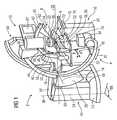
- Fig. 1 1shows a SWL system 2 in a first embodiment comprising the following subcomponents: an X-ray C-arm 4, a therapy C-arm 8 carrying a shockwave head 6, which characterizes the first embodiment, a patient table 10 and a display module 12
- the X-ray C-arm 4comprises a two-part main body 14, on which a C-arm segment 16 is movably mounted.
- a circular segment-shaped bearing 18(not visible) is present in the base body 14, in which the C-arm segment 16 is forcibly guided as free of play.
- the C-arm segment 16can therefore be moved one-dimensionally in the bearing 18 in the orbital direction indicated by the double arrow 20.
- the two-part main body 14comprises a base 24 which rests stationary. At this is rotatable about a horizontal pivot axis 26, a guide 28 via a rotary joint 30 is attached.
- the pivot axis 26intersects a longitudinal axis 22 in an isocenter 32.
- the X-ray C-arm 4can be angularly pivoted about the pivot axis 26.
- the orbital pivoting movement of the C-arm segment 16takes place at the in Fig. 1
- angular pivoting of the X-ray C-arm 4then takes place orbital pivoting about a corresponding to the longitudinal axis 22 tilted axis of rotation (not shown).
- an X-ray source 34 and an image intensifier 36are mounted at both ends of the C-arm segment 16.
- the X-ray source 34 and the image intensifier 36together form an imaging system whose central beam 38 also passes through the isocenter 32. This ensures that the central beam 38 pierces the isocenter 32 in each angular and orbital position of the C-arm segment 16.
- Fig. 1the C-arm segment 16 is shown in its basic position, ie the central beam 38 extends in the vertical direction.
- the central divergent beam 38biases an orbital plane 40 which includes the central beam 38 and the pivot axis 26.
- the orbital plane 40is in Fig. 1
- hatchingis shown only in a very small area, but also extends beyond the hatched area and the diameter of the X-ray C-arm 4.
- the therapy C-arm 8is mounted on its radially outer side 42 on a guide 44.
- a bearing 18 corresponding, non-visible bearing 46is present, on which the therapy C-arm 8 in the direction of arrow 48 orbital is movable.
- the guide 44With its end 50, the guide 44 is mounted on the bearing block 52 of a base body 54.
- a non-visible hinge 56 between the bearing block 52 and guide 44is arranged, which allows rotation about an axis parallel to the longitudinal axis 22 axis 58.
- guide rails with corresponding slide on the base body 54 and bearing block 52and be attached to the guide 44 on which the therapy C-arm 8 together with the guide 44, for example, parallel to the axis 26 is wegschiebbar from the patient area.
- guide railswith corresponding slide on the base body 54 and bearing block 52 and be attached to the guide 44 on which the therapy C-arm 8 together with the guide 44, for example, parallel to the axis 26 is wegschiebbar from the patient area.
- railsthere are also other arrangements of rails conceivable, so that the X-ray C-arm 4 together with the shockwave head. 6 along this within certain limits two-dimensionally movable.
- a carriage 62On the radially inner side 60 of the therapy C-arm 8, a carriage 62 is also mounted orbitally movable in the direction 48. On the carriage 62, a boom 64 is fixed with its fixing end 67, which points in the direction of the X-ray C-arm 4 and at its free end 66 carries the shockwave head 6.
- slide 62 on the therapy C-arm 8 and therapy C-arm 8 on the guide 44are moved simultaneously, for example, arranged in the interior of the therapy C-arm 8, in Fig. 1 invisible chain drive. The fact that the two aforementioned movements are no longer independent of each other is irrelevant to the functionality of Annex 2.
- the orbital movements of therapy C-arm 8 and slide 62are also carried out about the longitudinal axis 22nd
- the entire therapy C-arm 8 with its base body 54is offset by an axial distance to the X-ray C-arm 4 and the orbital plane 40 parallel, that is, the plane that spans the therapy C-arm 8, is parallel to Orbital plane 40 and spaced therefrom.
- the cantilever 64extends in the direction of the X-ray C-arm 4 so far that the shockwave head 6 fastened to it again lies in the orbital plane 40. The distance is dimensioned such that a focal point 70 of one emitted by the shockwave head 6, in Fig. 1
- the ultrasonic shock wave represented by the cone 72lies in the orbital plane 40, wherein the cone tip forms the focal point 70 and lies in the isocenter 32.
- the shockwave head 6is an ultrasonic shockwave head for generating an ultrasonic pulse focused in the focal point 70.
- the impact axis 68that is to say the propagation direction of the ultrasound pulse, leads through the focal point 70, lies in the orbital plane 40 and falls in Fig. 1 with the central beam 38 together. For this reason one speaks in Fig. 1 from one so-called in-line position of shockwave head 6 and X-ray system 34, 36.
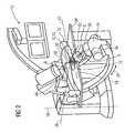
- an X-ray transparent zone 96 surrounding the bump axis 68 (in FIG Fig. 2 visible) in the shockwave head 6can namely take place during the shock wave treatment of a patient 76, a simultaneous X-ray localization of the object to be treated or a fluoroscopy of the environment of the focal point 70 in the interior of the patient's body.
- the X-rays emitted by the X-ray source 34can penetrate the X-ray transparent zone 96 of the shockwave head 6 along the central beam 38.
- the shockwave head 6is positioned on the ventral side of the patient, for example to treat a stone in the ureter of the patient. This is called the upper table treatment position.
- the treatment point of the SWL system 2, in which the focal point 70 is to be locatedalways lies in the isocenter 32.
- the patientIn an imaging phase of the treatment of the patient 76, the patient is therefore brought to the isocenter 32 with his or her treatment site (In Fig. 1 already happend).
- the imaging systemconsisting of x-ray source 34 and image intensifier 36 provides x-ray images, which are displayed on screens 82 of the display module 12.
- About the flexible, weight-balanced arm 84 of the screen 82are moved into a favorable viewing position for the operator of Appendix 2.
- At least two x-ray images of the patient 76is created in which the x-ray C-arm 4 about the axes 22 (orbital location) or 26 (angular location), for example between the in Fig.1 and Fig.2 pivoted positions is shown.
- a lying surface 78on which the patient 76 rests, is head-mounted on a permanently installed base 80 and linearly movable in all spatial directions 90.
- the introduction of the shockwave head 6 to the patient 76can be done in two ways. Either the treatment position of the patient 76 is first visited and then marked, stored electronically, for example, in the case of a motor-driven lying surface 78. The lying surface 78 together with the patient 76 is then moved a piece so that the shockwave head 6 in the in Fig. 1 shown position, then the patient 76 is approached to the shockwave head 8 from below until the stored above treatment position is reached again. Thus, the in Fig. 1 shown position produced.
- the treatmentcan be started by switching on the ultrasonic shockwave.
- Dodging of the shockwave head 6, due to its own weight and the contact pressure on the patient and the deformation of the therapy C-arm 8can be achieved e.g. be corrected by a slight pivoting of the therapy C-arm 8 about the axis 58.
- Fig. 2illustrated treatment position, namely the so-called lower table left position treated, for example, the left kidney of the patient 76.
- the shockwave head 6is pivoted in undercounter position.
- the in Fig. 2 from the X-ray source 34 concealed carriage 62is opposite Fig. 1 proceed to the opposite end of the therapy C-arm 8.
- the therapy C-arm 8itself in its guide 44 to the opposite Fig. 1 opposite end procedure.
- the shockwave head 6projects into a recess 92 of the lying surface 78 so as to be brought as close as possible to the patient 76 for direct contact.
- the cone 72 of the ultrasound beams generated by the shockwave head 6passes through a water-filled coupling bellows, which is coupled between shockwave head 6 and patient 76 with the interposition of gel and further the body tissue of the patient so far that the focal point 70, the center of a kidney stone, not shown in the Body of the patient 76 hits.
- the X-ray C-armis as in FIG Fig. 1 in basic position. However, he is pivoted in the direction of 20 counterclockwise by about 40 degrees to the patient 76 diagonally to illuminate.
- the 40 degree positionis a common location for the treatment of kidney stones.
- Fig. 2It can be seen that the shockwave head 6 is mounted eccentrically on the boom 64, namely on the plant side facing away from under table position of the boom 64. As a result, the shockwave head 6 is in the direction of the front side 94 of the lying surface further from the patient table 10 before the therapy C-arm. 8 and the boom 64. The doctor, who is usually standing at the front 94 next to the patient table 10, is thereby restricted as little as possible in his leg or freedom of movement. Since in upper table position the in Fig. 1 shown 180-degree position of the shockwave head 6 is the outermost position of the shockwave head 6, here is the supernatant of therapy C-arm 8 and boom 64 for the attending physician in the head area wearable. In addition, this provides another way to reduce the C-arm.
- Fig. 2the central X-ray transparent zone 96 is visible in the shockwave head 6, which serves for in-line location during shockwave treatment. Because of the stationary stationary isocenter 32, the lying surface 78 is opposite Fig. 1 slightly raised and moved to the right side of the patient to instead place his ureter whose left kidney at the treatment point, so the isocenter 32.
- Fig. 3shows the therapy C-arm 8 in parking position.
- the entire therapy C-arm 8 together with the shockwave head 6is made of the in Fig. 1 shown pivoted about the axis 58 upwards by about 90 degrees.
- the entire patient upper body areais released, which greatly facilitates access for treatment personnel to the patient 76. This is an advantage in an emergency situation or during pre-treatment or post-treatment.
- Fig. 4shows the SWL system 2 in an alternative embodiment, not geheaste to the invention, namely with an articulated arm 208 as a support device.
- the articulated arm 208is mounted with its one end 242 on the bearing block 244 of the main body 54.
- a joint 248 between the bearing block 244 and an arm segment 250is arranged, which allows rotation about an axis parallel to the longitudinal axis 22 axis 252.
- a further joint 256is mounted, which is pivotable about an axis 258 which is also parallel to the longitudinal axis 22.
- a further joint 262is attached, which connects the arm segment 254 with the boom 64 and allows its rotation together with the impact head 6 about the also parallel to the longitudinal axis 22 extending axis 266.
- the entire articulated arm 208 with its base body 46is offset in parallel by an axial distance to the X-ray C-arm 4 and the orbital plane 40, that is, the longitudinal axes of the arm segments 250 and 254 are parallel to the orbital plane 40.
- the boom 64extends in the direction on the X-ray C-arm 4 so far that the attached him shock head 6 is again in the orbital plane 40.
- the distanceis dimensioned such that the focal point 70 of the emitted from the impact head 6, in Fig. 4 is located in the orbital plane 40 shown by the cone 72 ultrasonic shock wave.
- the impact axis 68leads again through the focal point 70 and lies in the orbital plane 40.
- the focal point 70is only two-dimensionally displaceable, always within a limited by the dimensions of the articulated arm 208 area of the orbital plane 40. In particular, the focal point 70 be guided by pivoting the articulated arm 208 to the isocenter 32.
- Fig. 4the articulated arm 208 and the impact head 6 is moved into a so-called parking position, ie moved as far as possible out of the surrounding area of the patient 76 resting on the patient table 10. Access to the patient 76 from all sides for unrepresented treatment staff or doctors is thus possible without hindrance.
- an imaging phasemay be performed before or after treatment of the patient 76.
- the ultrasonic cone 72 and the focal point 70is shown, but the ultrasound source is usually off.
- the impact head 6is guided toward the patient by pivoting the articulated arm 208.
- the patientdoes not have to be moved again.
- the X-ray C-arm 2is in this case about the pivot axis 26 in the short term from his in Fig. 4 tilted away angular position shown in order to avoid a collision.
- the treatmentcan be started by turning on the ultrasonic shock wave.
- the entire X-ray C-arm 4is pivotable away from the patient area about the axis of rotation 86, which penetrates vertically the main body 14 and the foot part 74, which allows unrestricted access for the patient to the treatment staff 76.
- This parking position of the X-ray C-arm 4is in Fig. 5 shown.
- the articulated arm 208is instead moved to a treatment position in which the focal point 70 coincides with the isocenter 32.
- the right kidney from about 40 ° positioncan be treated backward of the patient 76 - this is the so-called under-table-right position.
- Winkelauf screeningIn the joints 248, 256 and 262 not shown Winkelauf screening are present, which detect the respective rotational position of the relevant joint and to a not shown Forward central computer.
- the respective position of the arm segments 250 and 252 and the shockwave head 6 and thus the focus point 70can be determined from the known dimensions of the entire articulated arm 208 by detecting the angles of rotation of the joints 248, 256 and 262 in the central computer in a suitable manner. This controls the motors, also not shown in the joints 248, 256 and 262 such that the focal point 70 comes to lie exactly in the isocenter 32. An automated control of the entire articulated arm 208 and its movement is thus enabled.
- Fig. 4drawn again dashed. Due to the space-saving arrangement of the articulated arm 208 on only one side of the patient 76, namely the right, which in Fig. 5 is also treatment side, the access to the patient is made possible with the greatest possible freedom.
- the impact head 6protrudes into a recess 92 of the lying surface 78 opposite the recess 92, in order to be brought as close as possible to the patient 76 for direct contact.
- the X-ray C-arm 4is disposed about the axis of rotation 86 (in FIG. 1) parallel to the orbital plane 40 and perpendicular to the axes of rotation 252, 258, and 266 Fig. 5 concealed) pivotable. Since the axes of rotation 252, 258, and 266 are usually horizontal, the orbital plane 40 is vertical, the axis of rotation 86 for the x-ray C-arm 2 is usually also perpendicular. The X-ray C-arm 2 can thus be pivoted away from the treatment area in the manner of movement of a door when it is not needed. Despite weggeschwenktem X-ray C-arm 4, the treatment of the patient 76 with the shockwave head 6 remains accurate to the location, since their spatial position to the SWL system 2 does not change.
- an inline ultrasonic locationis possible. Access to the patient 76 in fact, this is also possible from the machine-facing rear side of the patient table 10. By the offset to the head side of the patient 76 out link arm 208, the back of the shockwave head 6 is freely accessible.
- an unillustrated ultrasonic applicatorcan be used and thereby an ultrasonic location of the object to be treated in the patient's body are performed.
- the central openingis arranged approximately in the area of the X-ray transparent zone 96.
- Fig. 6shows an operating situation of the system 2, in which at the same time for the shock wave treatment of the patient 76 by means of the impact head 6, an X-ray fluoroscopy by means of the X-ray C-arm 4.
- the shockwave head 6is in the inline position.
- the X-rays emitted by the X-ray source 34can penetrate the shockwave head 6 through the X-ray transparent zone 96 along the central beam 38.
- the shockwave head 6 on the left side of the patientis correspondingly closed Fig. 5 positioned at about -40 ° to treat, for example, a kidney stone of the patient's left kidney (under-left position as in Fig.2 ). Because of the stationary stationary isocenter 32, the lying surface 78 is opposite Fig.
- the focal point 70coincides again with the isocenter 32.
- the X-ray assemblyis tilted about the longitudinal axis 22 to obliquely illuminate the patient 76.
- the recess 92 in the lying surface 78in turn provides space for the impact head. 6
- the impact head 6is movable in upper table position to treat the patient 76 from above, so the ventral side centrally in the ureter region.
- the shockwave head 6would be eg in Fig. 4 arranged on the abdominal upper side of the patient 76 between this and the image intensifier 36, so that at the same time again an X-ray fluoroscopy (inline) of the patient 76 can take place.
Landscapes
- Health & Medical Sciences (AREA)
- Surgery (AREA)
- Life Sciences & Earth Sciences (AREA)
- Heart & Thoracic Surgery (AREA)
- Molecular Biology (AREA)
- Vascular Medicine (AREA)
- Engineering & Computer Science (AREA)
- Biomedical Technology (AREA)
- Orthopedic Medicine & Surgery (AREA)
- Medical Informatics (AREA)
- Nuclear Medicine, Radiotherapy & Molecular Imaging (AREA)
- Animal Behavior & Ethology (AREA)
- General Health & Medical Sciences (AREA)
- Public Health (AREA)
- Veterinary Medicine (AREA)
- Apparatus For Radiation Diagnosis (AREA)
- Radiation-Therapy Devices (AREA)
- Surgical Instruments (AREA)
Abstract
Description
Translated fromGermanDie Erfindung betrifft eine Anlage zur bildgestützten Stoßwellenbehandlung. Die Hauptbestandteile einer solchen Anlage sind ein Therapiesystem und ein Röntgensystem. Das Therapiesystem umfasst einen Stoßwellenkopf, der auf einen Fokuspunkt gerichtete Ultraschallwellen erzeugt. Als Therapiezweck kommt vor allem die Zertrümmerung von Nieren- und Harnleitersteinen in Frage. Denkbar sind aber auch Anwendungen zur Behandlung der Induratio penis plastica oder im Bereich der Schmerztherapie und der Gastroenterologie. Das Röntgensystem dient zur Ortung des Steins im Behandlungsgebiet eines Patienten und zur therapiebegleitenden Beobachtung des Behandlungserfolges. Es umfasst eine Röntgenstrahlquelle und einen Röntgenempfänger bzw. Bildverstärker. Die beiden Geräte sind an den Schenkelenden eines um sein Isozentrum orbital verfahrbaren C-förmigen Bogens, im weiteren Röntgen-C-Bogen genannt, fixiert. Der Röntgen-C-Bogen umgreift im Anwendungsfall teilweise einen Patiententisch bzw. ist in Richtung einer rechtwinklig zu seiner Orbitalebene verlaufenden Achse von diesem durchsetzt.The invention relates to a system for image-based shock wave treatment. The main components of such a system are a therapy system and an X-ray system. The therapy system includes a shockwave head that generates ultrasonic waves directed at a focal point. The main purpose of therapy is the destruction of kidney and ureteral stones. Also conceivable are applications for the treatment of induratio penis plastica or in the field of pain therapy and gastroenterology. The X-ray system is used to locate the stone in the treatment area of a patient and to monitor the success of the treatment. It comprises an X-ray source and an X-ray receiver or image intensifier. The two devices are fixed to the leg ends of a C-shaped orbitally movable around its isocenter, hereinafter referred to as X-ray C-arm. The X-ray C-arm encompasses in the application partially a patient table or is in the direction of an axis perpendicular to its orbital plane passing through this axis.
Bei der Behandlung eines Patienten mit einer Anlage der oben geschilderten Art muss der Fokuspunkt des Stoßwellenkopfes auf das Isozentrum des Röntgen-C-Bogens ausgerichtet sein bzw. mit diesem zusammenfallen, damit bei einer zur 3D-Ortung erforderlichen orbitalen oder angularen Verfahrung des Röntgensystems dessen Strahlachse stets durch den Fokuspunkt bzw. durch einen diesen beinhaltenden Volumenbereich verläuft. Im Anwendungsfall muss dementsprechend das zu behandelnde Therapieobjekt ebenfalls in dem genannten Bereich angeordnet, d.h. der Patient in geeigneter Lage auf dem Patiententisch positioniert werden. Bei Anlagen mit feststehendem Stoßwellenkopf kann diese Forderung nur durch eine für den Patienten unangenehme Lage, beispielsweise durch eine insbesondere bei adipösen Patienten kritische Bauchlage erfüllt werden.In the treatment of a patient with a system of the type described above, the focal point of the shockwave head must be aligned with the isocenter of the X-ray C-arc or coincide with it, so that at a necessary for 3D detection orbital or angular Verfahren the X-ray system whose beam axis always passes through the focal point or by a volume range including this. In the case of use, accordingly, the therapeutic object to be treated must likewise be arranged in the named area, ie the patient must be positioned in a suitable position on the patient table. In systems with a fixed shockwave head, this requirement can only be made unpleasant for the patient Location, for example, be met by a particularly critical in obese patients prone position.
Bei einer aus
Aufgabe der Erfindung ist es, eine Anlage zur Stoßwellenbehandlung vorzuschlagen, die in dieser Hinsicht verbessert ist.The object of the invention is to propose a system for shock wave treatment, which is improved in this regard.
Diese Aufgabe wird durch eine Anlage nach Anspruch 1 gelöst. Diese umfasst einen orbital um ein Isozentrum verfahrbaren Röntgen-C-Bogen und eine zu diesem axial versetzt und ortsfest angeordnete Tragvorrichtung für den Stoßwellenkopf. Ein sich zum Röntgen-C-Bogen hin erstreckender Ausleger ist mit seinem Fixierende mit der Tragvorrichtung verbunden und trägt mit seinem Freiende den Stoßwellenkopf. Mit Hilfe der Tragvorrichtung ist der Ausleger derart beweglich geführt, dass der Stoßwellenkopf in der Orbitalebene innerhalb eines Winkelbereiches von mindestens 180° ober- und unterhalb eines Patiententisches beliebig positionierbar und auf das Isozentrum ausrichtbar ist. Durch die axial versetzte Anordnung der Tragvorrichtung ist der gesamte vom Röntgen-C-Bogen umschlossene Raum frei zugänglich. Dies erlaubt es, einen Patiententisch horizontal soweit zu verschieben, dass ein Behandlungswechsel von der rechten zur linken Patientenseite, also eine Positionierung des links- oder rechtsseitigen Behandlungsgebietes des Patienten im Isozentrum, erfolgen kann, ohne eine Kopf-zu-Fuß-Umlagerung des Patienten vornehmen zu müssen. Dadurch kann das ursprüngliche Setup der Anlage erhalten bleiben, was insbesondere dann vorteilhaft ist, wenn etwa ein Patient mit beidseitigen Nierensteinen behandelt wird. Aufgrund der Beweglichkeit des Auslegers und damit des Stoßwellenkopfes in einem Winkelbereich von mindestens 180° lässt sich letzterer beispielsweise in einer Untertischposition mit vertikaler Ausrichtung seiner Stoßwellenachse (0°-Position) und in einer Obertischposition mit gleicher Stoßwellenachsenausrichtung (180°-Position) anordnen. Bei einem Verschwenkbereich von 230° kann eine Verschwenkung von der vertikalen Obertischposition (180°) bis zu einer unter dem Tisch durchgeschwenkten -50°-Position erfolgen. Hierdurch sind nahezu alle Behandlungssituationen an einem Patienten in ein und derselben Patientenlage durchführbar. Im Extremfall kann die Tragvorrichtung so ausgestaltet sein, dass mit dem Stoßwellenkopf ein Winkelbereich von 360° abgedeckt werden kann. Es steht also eine große Variabilität hinsichtlich der Wahl der Behandlungsposition des Stoßwellenkopfs zur Verfügung, beispielsweise kann eine Ureterstein-Behandlung von einer Ober- oder Untertischposition aus bei Rückenlage des Patienten vorgenommen werden.This object is achieved by a system according to claim 1. This includes an orbital movable about an isocenter X-ray C-arm and one to this axially offset and stationary arranged supporting device for the shockwave head. A to the X-ray C-arm extending boom is connected with its fixation with the support device and carries with its free end the shockwave head. With the help of the support device, the boom is guided so movable that the shockwave head in the orbital plane within an angular range of at least 180 ° above and below a patient table can be positioned arbitrarily and aligned to the isocenter. Due to the axially offset arrangement of the support device, the entire space enclosed by the X-ray arc C is freely accessible. This makes it possible to move a patient table horizontally so far that a change of treatment from the right to the left side of the patient, ie a positioning of the left or right side treatment area of the patient in the isocenter can be done without a head-to-foot rearrangement of the patient to have to. As a result, the original setup of the system can be maintained, which is particularly advantageous if, for example, a patient is treated with bilateral kidney stones. Due to the mobility of the boom and thus the shockwave head in an angular range of at least 180 °, the latter can be arranged, for example, in a lower table position with vertical alignment of its shockwave axis (0 ° position) and in an upper table position with the same shockwave axis alignment (180 ° position). With a pivoting range of 230 °, pivoting can take place from the vertical upper table position (180 °) to a -50 ° position swept under the table. As a result, almost all treatment situations on a patient in one and the same patient situation are feasible. In extreme cases, the support device can be designed so that an angular range of 360 ° can be covered with the shockwave head. So there is a great variability in the choice of the treatment position of the shockwave head available, for example, a ureteral stone treatment can be made from a top or bottom table position in the supine position of the patient.
Ist die Tragvorrichtung für den Stoßwellenkopf bezüglich des Röntgen-C-Bogens in Kopfrichtung des Patienten angeordnet, so hat der Arzt bis auf Höhe der zu behandelnden Stelle des Patienten auch auf der maschinenzugewandten Seite vom Fußbereich des Patienten her freien Zugang zu diesem, so dass etwa ein transuretraler Eingriff behinderungsfrei möglich ist. Trotz der genannten Anordnung ist für einen im Kopfbereich des Patienten arbeitenden Anästhesist noch genügend Bewegungsfreiheit vorhanden.If the support device for the shockwave head with respect to the X-ray C-arm arranged in the head direction of the patient, the doctor has up to the level of the treatment area of the patient on the machine side facing the foot of the patient's free access to this, so that about a transuretral intervention is possible without hindrance. Despite the aforementioned arrangement, there is still sufficient freedom of movement for an anesthesiologist working in the head area of the patient.
Aufgrund der orbitalen Verfahrbarkeit des Röntgen-C-Bogens kann sowohl die Ortung als auch die Beobachtung während der Behandlung, etwa der Fortgang einer Steinzertrümmerung, aus Richtung der Stoßwellenachse erfolgen, was eine höhere Zielgenauigkeit bietet (Inline-Ortung). Eine Abschattung des Röntgenstrahls durch eine innerhalb des Röntgen-C-Bogens angeordnete Tragstruktur für den Stoßwellenkopf ist dabei nicht zu befürchten. Innerhalb des vom Röntgenstrahl des Röntgensystems überstrichenen Volumenbereichs ist lediglich der Stoßwellenkopf selbst angeordnet. Der ihn tragende Ausleger stört dabei nicht, insbesondere wenn dieser mit seinem Freiende den Stoßwellenkopf von der Seite her fasst. Zusammenfassend steht erfindungsgemäß somit eine Anlage zur Verfügung, die eine Stoßwellenbehandlung in beliebigen Winkelpositionen sowie aus unterschiedlichen Einschallwinkeln bei stets gleichbleibender Ausrichtung und Rückenlage des Patienten, sowie die zielgenaue Röntgen-Inline-Ortung und eine nahezu behinderungsfreie Beobachtung mit Hilfe des Röntgensystems während der Behandlung gestattet. Die Anlage ist daher für eine Vielzahl von Anwendungen, beispielsweise der IPP, Nieren-, Ureter- und Blasensteine, transuretrale Eingriffe gleichermaßen geeignet.Due to the orbital traversability of the X-ray C-arm, both the location and the observation during the treatment, such as the progress of a Steinzertrümmerung, take place from the direction of the shock wave axis, which provides a higher accuracy (inline location). Shading of the X-ray beam by a support structure for the shockwave head arranged inside the X-ray C-arm is not to be feared here. Within the volume range swept by the X-ray beam of the X-ray system, only the shockwave head itself is arranged. The boom supporting it does not interfere with this, especially when it seizes the shockwave head from the side with its free end. In summary, according to the invention thus a system is available, which allows a shock wave treatment in any angular positions and from different Einschallwinkeln always consistent orientation and supine position of the patient, as well as the targeted X-ray inline positioning and a nearly disability-free observation with the help of the X-ray system during treatment. The system is therefore suitable for a variety of applications, such as IPP, renal, ureteral and bladder stones, transureteral interventions alike.
Dadurch, dass beide Teilsysteme, nämlich das Röntgensystem und das Therapiesystem ortsfest zueinander, bspw. an einem gemeinsamen Grundkörper gebracht sind, ist deren relative Position zueinander mechanisch festgelegt. So kann etwa bei der Montage der Anlage eine Justierung dahingehend erfolgen, dass der Fokuspunkt des Stoßwellenkopfes in jeder Behandlungsposition auf das Isozentrum gerichtet ist bzw. mit diesem zusammen fällt. Der Einsatz etwa eines elektronischen Ortungssystems zur Positionsfeststellung bzw. Berechnung der Lage von Fokus- und Isozentrum ist daher nicht erforderlich.The fact that both subsystems, namely the X-ray system and the therapy system are stationary relative to one another, for example, are brought to a common base body, is their relative position mechanically fixed to each other. For example, during the installation of the system, an adjustment can be made to the effect that the focal point of the shockwave head is directed to the isocenter in each treatment position or coincides with it. The use of an electronic locating system for position detection or calculation of the position of focus and isocenter is therefore not required.
Der Ausleger ist in einer zur Orbitalebene des Röntgen-C-Bogens parallelen Ebene zwangsgeführt. Ein seitliches Ausweichen des Fokuspunktes des Stoßwellenkopfes aus der Orbitalebene des Röntgen-C-Bogens ist dadurch verhindert.The cantilever is constrained in a plane parallel to the orbital plane of the X-ray C-arm. A lateral deflection of the focal point of the shockwave head from the orbital plane of the X-ray C-arm is prevented.
Die Tragvorrichtung ist in zum Röntgen-C-Bogen axial versetzt und koaxial angeordneter C-Bogen (im weiteren als Therapiebogen bezeichnet), an dem der Ausleger mit seinem Fixierende orbital verfahrbar gelagert ist. Diese Ausgestaltung gestattet eine vollständig zwangsgeführte Bewegung des Stoßwellenkopfes in der Orbitalebene des Röntgen-C-Bogens. Eine bei der Neuinstallation einer Anlage vorgenommene Justierung des Fokuspunktes des Stoßwellenkopfes auf das Isozentrum des Röntgen-C-Bogens bleibt erhalten.The support device is offset axially to the x-ray C-arm and coaxially arranged C-arm (hereinafter referred to as Therapy arc), on which the boom is mounted orbitally movable with its fixing. This configuration allows a complete positive guided movement of the shockwave head in the orbital plane of the X-ray C-arm. An adjustment of the focal point of the shockwave head to the isocenter of the X-ray C-arm made during the reinstallation of a system is retained.
Eine Verfahrung des Stoßwellenkopfes um einen bestimmten Winkelbereich setzt im Nörmalfall einen Therapiebogen mit mindestens entsprechend bemessener Bogenlänge voraus. Bei einer Verfahrbarkeit des Stoßwellenkopfes bspw. um 250° würde ein entsprechend bemessener Therapiebogen einen Behandlungstisch ober- und unterseitig weit übergreifen und dadurch die Bewegungsfreiheit eines behandelnden Arztes auf der Behandlungsseite des Patiententisches einschränken. Um dies zu verhindern, weist eine bevorzugte Anlagenvariante einen Therapiebogen auf, der orbital verfahrbar gelagert ist. Der Therapiebogen kann nun wesentlich kürzer sein, da sich der maximale Verfahrweg des Stoßwellenkopfes aus der Verfahrstrecke des Therapiebogens einerseits und der Verfahrstrecke des Stoßwellenkopfes am Therapiebogen andererseits ergibt. Zur Verkürzung der Therapiebogenlänge ist es auch denkbar, dass dieser aus zwei gegeneinander orbital verschiebbaren Bogensegmenten gebildet ist. Eine andere Möglichkeit zur Bogenverkürzung besteht darin, den Ausleger so am Therapiebogen drehbar zu fixieren, dass sein Freiende in eine über ein Schenkelende des Therapiebogens hinausragende Position geschwenkt werden kann.A passage of the shockwave head by a certain angle range requires in Nörmalfall a Therapy arc with at least appropriately sized arc length. At a mobility of the shockwave head, for example. By 250 ° a suitably sized Therapy arc would overlap a treatment table top and bottom sides and thereby restrict the freedom of movement of a doctor on the treatment side of the patient table. In order to prevent this, a preferred variant of the system has a therapy arch which is orbitally displaceable. The Therapy arc can now be much shorter, since the maximum travel of the shockwave head from the travel distance of Therapy arc on the one hand and the travel distance of the shockwave head on Therapy arc on the other hand results. To shorten the treatment arch length, it is also conceivable that this is formed of two mutually orbitally displaceable arc segments. Another possibility for sheet shortening is to fix the boom rotatably on the therapy arch so that its free end can be pivoted into a projecting beyond a leg end of the therapy arch position.
Bei einer zweiten Ausführungsform der Anlage die nicht zur Erfindung gehöst, ist die Tragvorrichtung ein mehrere über Gelenke verbundene Armsegmente aufweisender Gelenkarm, mit dessen Freiende das Fixierende des Auslegers verbunden ist. Während mit einem Therapiebogen eine Festlegung der Bewegung des Auslegers bzw. des Stoßwellenkopfes auf einer Kreisbahn verbunden ist, können die gewünschten Behandlungspositionen des Stoßwellenkopfes bei Verwendung eines Gelenkarms als Tragvorrichtung mit beliebigen Bewegungsbahnen angefahren werden, wobei dann eine Steuereinrichtung zur isozentrischen Ausrichtung des Stoßwellenkopfes erforderlich ist. Bei einer vorteilhaften Ausgestaltung ist der Freiheitsgrad des Gelenkarmes so eingeschränkt, dass er sich nur innerhalb einer zur Orbitalebene des Röntgen-C-Bogens parallelen Ebene bewegen kann. Dies wird zweckmäßiger Weise dadurch erreicht, dass die die Armsegmente verbindenden Gelenke des Gelenkarmes parallel zueinander und rechtwinklig zur Orbitalebene des Röntgen-C-Bogens verlaufende Drehachsen aufweisen, also all Scharniergelenke ausgebildet sind. Um den Stoßwellenkopf in jeder Winkelposition isozentrisch ausrichten zu können, ist der Ausleger drehbar mit dem Freiende des Gelenkarms verbunden.In a second embodiment of the system which is not part of the invention, the support device is a more articulated via joints arm segments exhibiting articulated arm, with the free end of the fixing end of the boom is connected. While a therapy arc, a determination of the movement of the boom or the shockwave head is connected in a circular path, the desired treatment positions of the shockwave head can be approached when using an articulated arm as a support device with any trajectories, in which case a control device for isocentric alignment of the shockwave head is required. In an advantageous embodiment, the degree of freedom of the articulated arm is limited so that it can only move within a plane parallel to the orbital plane of the X-ray C-arm. This is expediently achieved by virtue of the fact that the joints of the articulated arm connecting the arm segments have axes of rotation running parallel to one another and at right angles to the orbital plane of the X-ray C-arm, ie, all hinge joints are formed. In order to align the shockwave head in each angular position isocentric, the boom is rotatably connected to the free end of the articulated arm.
Bei beiden Ausführungsformen ist ein Stoßwellenkopf vorgesehen, der von einem für Röntgenstrahlen durchlässigen, sich längs seiner Stoßwellenachse erstreckenden Zentralbereich durchsetzt ist. Diese Ausgestaltung lässt eine zielgenaue "Inline-Ortung" mit dem Röntgensystem ohne Lageveränderung des Stoßwellenkopfes, also auch während einer Lithotripsiebehandlung zu. Bei einer ebenfalls für beide Ausführungsformen vorteilhaften Ausgestaltung ist die Tragvorrichtung zusammen mit dem Stoßwellenkopf aus einer Behandlungsstellung in eine von einem Patiententisch bzw. einem darauf gelagerten Patienten entfernte Parkposition verfahrbar. Dadurch kann die Bewegungsfreiheit in dem sich zwischen Röntgen-C-Bogen und Kopfseite des Patiententisches befindlichen Raum bzw. allgemein im Abdominalbereich des Patienten erhöht werden.In both embodiments, a shockwave head is provided, which is penetrated by a permeable to X-rays, along its shockwave axis extending central region. This refinement allows an accurate "inline localization" with the X-ray system without changing the position of the shockwave head, thus also during a lithotripsy treatment to. In an embodiment which is also advantageous for both embodiments, the carrying device, together with the shockwave head, can be moved from a treatment position into a parking position remote from a patient table or a patient seated thereon. As a result, the freedom of movement in the space located between the x-ray C-arm and the head side of the patient table or generally in the abdominal area of the patient can be increased.
Um eine Orbitalverfahrung des Röntgen-C-Bogens und des Therapiebogens bzw. eine Bewegung des Gelenkarms auf der Unterseite des Patiententisches nicht zu behindern, ist dieser endseitig, beispielsweise kopfseitig, also außerhalb des Bewegungsbereiches der genannten Vorrichtungen, gelagert.In order not to hinder an orbital movement of the X-ray C-arm and the therapy arch or a movement of the articulated arm on the underside of the patient table, this is the end, for example, the head, ie outside the range of movement of said devices stored.
Für eine weitere Beschreibung der Erfindung wird auf die Ausführungsbeispiele der Zeichnungen verwiesen. Es zeigen, jeweils in einer perspektivischen Prinzipdarstellung:
Fig. 1 eine Stoßwellen-Lithotripsie-Anlage in einer ersten Ausführungsform mit Stoßwellenkopf in Obertisch-Behandlungsposition und Röntgen-C-Bogen in Grundposition (Inline zum Stoßwellenkopf),Fig. 2 die Anlage ausFig. 1 mit Stoßwellenkopf in Untertisch-Behandlungsposition für die linke (maschinenferne) Patientenseite mit orbital in Inline-Position verschwenktem Röntgensystem,Fig. 3 die Anlage ausFig. 1 mit Therapie-C-Bogen und Stoßwellenkopf in Parkposition.Fig. 4 die Stoßwellen-Lithotripsie-Anlage in einer zweiten Ausführungsform die nicht zur Erfindung gehöst, mit Gelenkarm und Stoßkopf in Parkposition und Röntgen-C-Bogen in Grundposition,Fig. 5 die SWL-Anlage ausFig. 4 mit geparktem, also ausgeschwenktem Röntgen-C-Bogen und Stoßkopf in Behandlungsposition (Untertisch - rechts),Fig. 6 die Anlage ausFig. 4 mit Stoßkopf in Behandlungsposition (Untertisch - links) und gekipptem Röntgen-C-Bogen in Inline-Position.
Fig. 1 a shockwave lithotripsy system in a first embodiment with shockwave head in upper table treatment position and X-ray C-arm in basic position (inline to the shockwave head),Fig. 2 the plant offFig. 1 with shockwave head in undercounter treatment position for the left (machine-distant) patient side with orbitally in-line pivoted X-ray system,Fig. 3 the plant offFig. 1 with therapy C-arm and shockwave head in parking position.Fig. 4 the shock wave lithotripsy system in a second embodiment, not part of the invention, with articulated arm and impact head in parking position and X-ray C-arm in basic position,Fig. 5 the SWL system offFig. 4 with parked, ie swung out X-ray C-arm and impact head in treatment position (lower table - right),Fig. 6 the plant offFig. 4 with impact head in treatment position (lower table - left) and tilted X-ray C-arm in inline position.
Der zweiteilige Grundkörper 14 umfasst einen Sockel 24, der ortsfest ruht. An diesem ist, um eine waagerecht verlaufende Schwenkachse 26 drehbar, eine Führung 28 über ein Drehgelenk 30 angebracht. Die Schwenkachse 26 schneidet eine Längsachse 22 in einem Isozentrum 32. Um die Schwenkachse 26 ist der Röntgen-C-Bogen 4 angular verschwenkbar. Die orbitale Verschwenkbewegung des C-Bogen-Segments 16 erfolgt bei der in
An den beiden Enden des C-Bogen-Segments 16 sind eine Röntgenquelle 34 und ein Bildverstärker 36 montiert. Die Röntgenquelle 34 und der Bildverstärker 36 bilden zusammen ein Bildgebungssystem, dessen Zentralstrahl 38 ebenfalls durch das Isozentrum 32 verläuft. So ist sichergestellt, dass der Zentralstrahl 38 in jeder Angular- und Orbitalposition des C-Bogen-Segments 16 das Isozentrum 32 durchstößt.At both ends of the C-
In
Der Therapie-C-Bogen 8 ist an seiner radial außen liegenden Seite 42 an einer Führung 44 gelagert. In der Führung 44 ist hierzu ein dem Lager 18 entsprechendes, nicht sichtbares Lager 46 vorhanden, an dem der Therapie-C-Bogen 8 in Richtung des Pfeils 48 orbital verfahrbar ist. Mit ihrem Ende 50 ist die Führung 44 am Lagerbock 52 eines Grundkörpers 54 gelagert. Hierbei ist ein nicht sichtbares Gelenk 56 zwischen Lagerbock 52 und Führung 44 angeordnet, welches eine Drehung um eine zur Längsachse 22 parallele Achse 58 erlaubt.The therapy C-
Alternativ oder zusätzlich zur dargestellten Ausführungsform können auch in den Figuren nicht dargestellte Führungsschienen mit entsprechenden Schlitten am Grundkörper 54 bzw. Lagerbock 52 und an der Führung 44 angebracht sein, auf denen der Therapie-C-Bogen 8 zusammen mit der Führung 44 z.B. parallel zur Achse 26 aus dem Patientenbereich wegschiebbar ist. Es sind auch andere Anordnungen von Schienen denkbar, so dass der Röntgen-C-Bogen 4 zusammen mit dem Stoßwellenkopf 6 entlang dieser in gewissen Grenzen zweidimensional bewegbar ist.Alternatively or in addition to the illustrated embodiment, not shown in the figures, guide rails with corresponding slide on the
An der radial innen liegenden Seite 60 des Therapie-C-Bogens 8 ist ein Schlitten 62 ebenfalls in Richtung 48 orbital verfahrbar gelagert. Am Schlitten 62 ist ein Ausleger 64 mit seinem Fixierende 67 befestigt, der in Richtung zum Röntgen-C-Bogen 4 hin weist und an seinem Freiende 66 den Stoßwellenkopf 6 trägt. Zum orbitalen Verfahren des Stoßkopfes 6 werden Schlitten 62 am Therapie-C-Bogen 8 und Therapie-C-Bogen 8 an der Führung 44 gleichzeitig verfahren, z.B. über einen im Inneren des Therapie-C-Bogens 8 angeordneten, in
Der gesamte Therapie-C-Bogen 8 mit seinem Grundkörper 54 ist um einen Axialabstand zum Röntgen-C-Bogen 4 bzw. zur Orbitalebene 40 parallel versetzt, das heißt, die Ebene, die der Therapie-C-Bogen 8 aufspannt, liegt parallel zur Orbitalebene 40 und zu dieser beabstandet. Der Ausleger 64 erstreckt sich in Richtung auf den Röntgen-C-Bogen 4 soweit hin, dass der an ihm befestigte Stoßwellenkopf 6 wiederum in der Orbitalebene 40 liegt. Der Abstand ist derart bemessen, dass ein Fokuspunkt 70 einer vom Stoßwellenkopf 6 ausgesandten, in
Die Stoßachse 68, also die Ausbreitungsrichtung des Ultraschallpulses, führt hierbei durch den Fokuspunkt 70, liegt in der Orbitalebene 40 und fällt in
Durch die koaxiale Anordnung von Röntgen-C-Bogen 4 und Therapie-C-Bogen 8 bleibt die Lage des Fokuspunktes 70 im Isozentrum 32 in jeder Verfahrposition des Stoßwellenkopfes 6 erhalten. Die Stoßachse 68 liegt immer in der Orbitalebene 40.Due to the coaxial arrangement of X-ray C-arm 4 and therapy C-
Die exakte geometrische Ausrichtung von Gelenkarm 8 und Röntgen-C-Bogen 4 zueinander erfolgt dadurch, dass der Grundkörper 14 und der Grundkörper 54 auf einem gemeinsamen Fußteil 74 montiert sind. Die Ausrichtung wird hierbei bei der Herstellung der SWL-Anlage 2 im Werk vorgenommen.The exact geometric orientation of articulated
Der Behandlungspunkt der SWL-Anlage 2, in dem der Fokuspunkt 70 zu lazieren ist, liegt immer im Isozentrum 32. In einer Bildgebungsphase der Behandlung des Patienten 76 wird dieser deshalb mit seiner zu behandelnden Stelle ins Isozentrum 32 gebracht (In
Das Heranführen des Stoßwellenkopfes 6 an den Patienten 76 kann auf zwei Arten erfolgen. Entweder wird die Behandlungsposition des Patienten 76 zuerst aufgesucht und dann markiert, z.B. bei einem motorisch verfahrbaren Liegefläche 78 elektronisch gespeichert. Die Liegefläche 78 zusammen mit dem Patienten 76 wird danach ein Stück verfahren, damit der Stoßwellenkopf 6 in die in
Alternativ kann wegen des um die Achse 58 schwenkbaren gesamten Therapie-C-Bogens 8 die Ankopplung des Stoßwellenkopfes 6 auch an den in Behandlungsposition gebrachten und von nun an ruhenden Patienten 76 erfolgen, indem der vorher nach oben geschwenkte Therapie-C-Bogen 8 zusammen mit dem Stoßwellenkopf 6 auf den nach oben weisenden Bauch des Patienten 76 abgesenkt wird. Diese Ankoppelvariante gilt insbesondere für die Ausführungsform der SWL-Anlage 2 gemäß
Ist der Stoßwellenkopf 6 an den Patienten 76 angekoppelt, kann mit der Behandlung durch Einschalten der Ultraschallstoßwelle begonnen werden.If the
Um eine weitere Drehachse 86, die senkrecht den Grundkörper 14 und das Fußteil 74 durchsetzt, ist der gesamte Röntgen-C-Bogen 4 aus dem Patientenbereich weg schwenkbar (in den Figuren nicht dargestellt), wenn er gerade nicht benötigt wird, was den Zugang für das Behandlungspersonal zum Patienten 76 erhöht. Das Verschwenken erfolgt aus der in
Ein Ausweichen des Stoßwellenkopfes 6, bedingt durch sein Eigengewicht und den Anpressdruck am Patienten und die Verformung des Therapie-C-Bogens 8 kann z.B. durch eine leichte Verschwenkung des Therapie-C-Bogens 8 um die Achse 58 korrigiert werden.Dodging of the
Die in
Bezüglich der Achse 26 befindet sich der Röntgen-C-Bogen wie in
In
In
Der Gelenkarm 208 ist mit seinem einen Ende 242 am Lagerbock 244 des Grundkörpers 54 gelagert. Hierbei ist ein Gelenk 248 zwischen Lagerbock 244 und einem Armsegment 250 angeordnet, welches eine Drehung um eine zur Längsachse 22 parallele Achse 252 erlaubt. Zwischen dem Armsegment 250 und einem weiteren Armsegment 254 ist ein weiteres Gelenk 256 angebracht, welches um eine ebenfalls parallel zur Längsachse 22 verlaufende Achse 258 schwenkbar ist. Am Freiende 260 des Gelenkarms 208 ist ein weiteres Gelenk 262 angebracht, welches das Armsegment 254 mit dem Ausleger 64 verbindet und dessen Drehung zusammen mit dem Stoßkopf 6 um die ebenfalls parallel zur Längsachse 22 verlaufende Achse 266 erlaubt.The articulated
Der gesamte Gelenkarm 208 mit seinem Grundkörper 46 ist um einen Axialabstand zum Röntgen-C-Bogen 4 bzw. zur Orbitalebene 40 parallel versetzt, das heißt, die Längsachsen der Armsegmente 250 und 254 verlaufen parallel zur Orbitalebene 40. Der Ausleger 64 erstreckt sich in Richtung auf den Röntgen-C-Bogen 4 soweit hin, dass der an ihm befestigte Stoßkopf 6 wiederum in der Orbitalebene 40 liegt. Der Abstand ist derart bemessen, dass der Fokuspunkt 70 der vom Stoßkopf 6 ausgesandten, in
Durch die Parallelität sämtlicher Achsen 252, 258 und 266, um welche die Einzelteile des Gelenkarms 208 schwenkbar sind, ist der Fokuspunkt 70 lediglich zweidimensional verschiebbar und zwar stets innerhalb eines durch die Abmessungen des Gelenkarms 208 begrenzten Bereiches der Orbitalebene 40. Insbesondere kann der Fokuspunkt 70 durch Verschwenken des Gelenkarms 208 zum Isozentrum 32 geführt werden.Due to the parallelism of all the
In
Liegt der zu behandelnde Körperbereich des Patienten 76 im Isozentrum 32, so wird der Stoßkopf 6 durch Verschwenken des Gelenkarms 208 zum Patienten hin geführt. Der Patient muss hierzu nicht erneut bewegt werden. Der Röntgen-C-Bogen 2 ist hierbei um die Schwenkachse 26 kurzfristig aus seiner in
Um die Drehachse 86, die senkrecht den Grundkörper 14 und das Fußteil 74 durchsetzt, ist der gesamte Röntgen-C-Bogen 4 aus dem Patientenbereich weg schwenkbar, was den uneingeschränkten Zugang für das Behandlungspersonal zum Patienten 76 ermöglicht. Diese Parkposition des Röntgen-C-Bogens 4 ist in
In den Gelenken 248, 256 und 262 sind nicht dargestellte Winkelaufnehmer vorhanden, welche die jeweilige Drehposition des betreffenden Gelenks erfassen und an einen nicht dargestellten Zentralrechner weiterleiten. Die jeweilige Position der Armsegmente 250 und 252 bzw. des Stoßwellenkopfes 6 und somit des Fokuspunkts 70 kann aus den bekannten Abmessungen des gesamten Gelenkarms 208 durch Erfassung der Drehwinkel der Gelenke 248, 256 und 262 auf geeignete Weise im Zentralrechner ermittelt werden. Dieser steuert die ebenfalls nicht dargestellten Motoren in den Gelenken 248, 256 und 262 derart an, dass der Fokuspunkt 70 exakt im Isozentrum 32 zu liegen kommt. Eine automatisierte Steuerung des gesamten Gelenkarms 208 bzw. dessen Bewegung ist so ermöglicht.In the
Auf Grund des weg geschwenkten Röntgen-C-Bogens 4 sind die Längsachse 22, Schwenkachse 26 und Zentralstrahl 38 aus
Der Röntgen-C-Bogen 4 ist um die parallel zur Orbitalebene 40 und senkrecht zu den Drehachsen 252, 258, und 266 verlaufende Drehachse 86 (in
In einer derartigen Position der SWL-Anlage 2 ist dann eine Inline-Ultraschallortung möglich. Der Zugang zum Patienten 76 ist dann nämlich auch von der maschinenzugewandten Rückseite des Patiententisches 10 möglich. Durch den zur Kopfseite des Patienten 76 hin versetzten Gelenkarm 208 ist die Rückseite des Stoßwellenkopfes 6 frei zugänglich. So kann in eine nicht dargestellte zentrale Öffnung im Stoßwellenkopf 6 ein nicht dargestellter Ultraschall-Applikator eingesetzt werden und hierdurch eine Ultraschallortung des zu behandelnden Objekts im Patientenkörper durchgeführt werden. Die zentrale Öffnung ist etwa im Bereich der röntgentransparenten Zone 96 angeordent.In such a position of the
Aus
Befinden sich Patient 76 und Liegefläche 78 sich in einer seitlichen Mittenposition zwischen den in
Claims (5)
- Installation (2) for image-supported shockwave treatment, with the following embodiment:- it comprises an X-ray C-arm (4), which can be displaced in an orbit about an isocentre (32) and has an X-ray system (34, 36), a shockwave head (6) and a support device for the shockwave head (6) arranged laterally from, and stationary with respect to, the X-ray C-arm (4),- a boom (64) that extends towards the X-ray C-arm (4) is connected to the support device at its fixed end (67) and carries the shockwave head (6) at its free end (66),- the boom (64) is moveably guided with the aid of the support device,characterized in that the boom (64) is moveably guided such that the shockwave head (6) can be positioned anywhere in the orbital plane (40) within an angular range of at least 180° above and below a patient table (10) and aligned with respect to the isocentre (32),- the boom (64) is forcibly guided in a plane parallel to the orbital plane (40) of the X-ray C-arm (4),- the support device is a coaxially arranged C-arm (8), which is axially offset with respect to the X-ray C-arm (4) and on which the boom (64) is mounted with its fixed end (67) such that it can be displaced in its orbit, and- the C-arm (8) is mounted such that it can be displaced in its orbit.
- Installation (2) according to Claim 1, in which the shockwave head (6) is penetrated by a central region (96) that is permeable to X-ray radiation and extends along its shockwave axis (68).
- Installation (2) according to one of the preceding claims, in which the X-ray C-arm (4) can be pivoted in an angular fashion.
- Installation (2) according to one of the preceding claims, in which the support device together with the shockwave head (6) can be displaced from a treatment position into a park position which is at a distance from the patient table (10) or a patient (76) positioned thereon.
- Installation (2) according to one of the preceding claims, with a patient table (10) penetrating the X-ray C-arm (4), which patient table is mounted outside of the displacement range of X-ray C-arm (4) and support device.
Applications Claiming Priority (2)
| Application Number | Priority Date | Filing Date | Title |
|---|---|---|---|
| DE102004010005ADE102004010005B4 (en) | 2004-03-01 | 2004-03-01 | Plant for image-based shock wave treatment |
| PCT/EP2005/050704WO2005082261A1 (en) | 2004-03-01 | 2005-02-17 | Installation used for image-assisted shockwave therapy |
Publications (2)
| Publication Number | Publication Date |
|---|---|
| EP1720467A1 EP1720467A1 (en) | 2006-11-15 |
| EP1720467B1true EP1720467B1 (en) | 2011-09-14 |
Family
ID=34894910
Family Applications (1)
| Application Number | Title | Priority Date | Filing Date |
|---|---|---|---|
| EP05716724ACeasedEP1720467B1 (en) | 2004-03-01 | 2005-02-17 | Installation used for image-assisted shockwave therapy |
Country Status (6)
| Country | Link |
|---|---|
| US (1) | US7725166B2 (en) |
| EP (1) | EP1720467B1 (en) |
| JP (1) | JP2007525296A (en) |
| CN (1) | CN100525722C (en) |
| DE (1) | DE102004010005B4 (en) |
| WO (1) | WO2005082261A1 (en) |
Families Citing this family (16)
| Publication number | Priority date | Publication date | Assignee | Title |
|---|---|---|---|---|
| DE102004010004B4 (en) | 2004-03-01 | 2006-04-27 | Siemens Ag | Plant for non-invasive medical treatment |
| DE102006009716B4 (en)* | 2006-03-02 | 2009-09-17 | Siemens Ag | lithotripsy |
| EP2059303A1 (en)* | 2006-08-30 | 2009-05-20 | Koninklijke Philips Electronics N.V. | Apparatus for thermal treatment of tissue |
| US20080281199A1 (en)* | 2007-05-09 | 2008-11-13 | Healthtronics, Inc. | System and method for a dual shock source lithotripsy system |
| EP2050401A1 (en)* | 2007-10-19 | 2009-04-22 | Dornier MedTech Systems GmbH | Lithotripter with a holding arm |
| EP2286743B1 (en) | 2009-08-19 | 2013-07-31 | Dornier MedTech Systems GmbH | Lithotripsy apparatus |
| DE102009048361A1 (en)* | 2009-10-06 | 2011-04-07 | Richard Wolf Gmbh | Medical therapy device |
| FR2958530B1 (en)* | 2010-04-13 | 2013-02-15 | Edap Tms France | PRESSURE WAVE TREATMENT APPARATUS EQUIPPED WITH A SYSTEM FOR MOVING THE ARM FROM AN X-RAY IMAGING SYSTEM |
| US10639503B2 (en) | 2014-08-27 | 2020-05-05 | Fusmobile Inc. | Handheld devices for projecting focused ultrasound and related methods |
| CN104546065A (en)* | 2015-01-16 | 2015-04-29 | 刘之俊 | In vitro lithotripter in urinary surgery |
| WO2017027577A1 (en)* | 2015-08-10 | 2017-02-16 | Fusmobile Inc. | Image guided focused ultrasound treatment device and aiming apparatus |
| JP2017093478A (en)* | 2015-11-18 | 2017-06-01 | 三鷹光器株式会社 | Stereoscopic observation apparatus for surgery |
| CN107080570A (en)* | 2017-06-16 | 2017-08-22 | 北京索迪医疗器械开发有限责任公司 | A kind of new extra chock wave lithotriptor |
| CN110302044B (en)* | 2019-07-12 | 2021-12-07 | 李卫 | Diameter-variable ring type shock wave treatment head |
| WO2022031672A1 (en)* | 2020-08-03 | 2022-02-10 | Rudy Alexander Riveron | Tissue configuration platform |
| CN115990051B (en)* | 2022-12-13 | 2024-06-04 | 索诺利(厦门)医疗科技有限公司 | Focus correction method for shock wave generator installation |
Family Cites Families (13)
| Publication number | Priority date | Publication date | Assignee | Title |
|---|---|---|---|---|
| US5065741A (en)* | 1987-04-16 | 1991-11-19 | Olympus Optical Co. Ltd. | Extracoporeal ultrasonic lithotripter with a variable focus |
| DE3919083C1 (en)* | 1989-06-10 | 1990-06-21 | Dornier Medizintechnik Gmbh, 8000 Muenchen, De | |
| EP0405282A1 (en)* | 1989-06-30 | 1991-01-02 | Siemens Aktiengesellschaft | Apparatus for treatment of a living body with focused shockwaves |
| JPH0819183A (en) | 1994-06-30 | 1996-01-19 | Meidensha Corp | System for prevention of single operation of nonutility power-generation installation linked to electric-power system |
| JPH08191836A (en)* | 1995-01-19 | 1996-07-30 | Toshiba Corp | Shock wave therapy system |
| DE19520748C2 (en)* | 1995-06-07 | 1999-09-02 | Siemens Ag | Therapy device with a radiation source |
| DE29824080U1 (en)* | 1998-02-27 | 2000-05-25 | Dornier Medtech Holding International GmbH, 82234 Weßling | Shock wave therapy system and location system in one isocentric system |
| DE10012878B4 (en)* | 2000-03-16 | 2004-09-30 | Siemens Ag | Device for generating acoustic waves |
| JP2001095811A (en)* | 2000-09-11 | 2001-04-10 | Toshiba Corp | Ultrasound therapy equipment |
| DE10145852B4 (en)* | 2001-09-17 | 2005-08-25 | Richard Wolf Gmbh | Medical device |
| CN2553743Y (en)* | 2002-07-20 | 2003-06-04 | 匡奕宁 | External shock wave lithotriptor |
| DE10236177B4 (en)* | 2002-08-07 | 2006-04-27 | Dornier Medtech Systems Gmbh | lithotripter |
| DE102004010004B4 (en)* | 2004-03-01 | 2006-04-27 | Siemens Ag | Plant for non-invasive medical treatment |
- 2004
- 2004-03-01DEDE102004010005Apatent/DE102004010005B4/ennot_activeExpired - Fee Related
- 2005
- 2005-02-17JPJP2007501265Apatent/JP2007525296A/enactivePending
- 2005-02-17CNCNB200580006741XApatent/CN100525722C/ennot_activeExpired - Fee Related
- 2005-02-17USUS10/587,781patent/US7725166B2/ennot_activeExpired - Fee Related
- 2005-02-17EPEP05716724Apatent/EP1720467B1/ennot_activeCeased
- 2005-02-17WOPCT/EP2005/050704patent/WO2005082261A1/ennot_activeApplication Discontinuation
Also Published As
| Publication number | Publication date |
|---|---|
| CN100525722C (en) | 2009-08-12 |
| JP2007525296A (en) | 2007-09-06 |
| WO2005082261A1 (en) | 2005-09-09 |
| EP1720467A1 (en) | 2006-11-15 |
| US7725166B2 (en) | 2010-05-25 |
| US20070276297A1 (en) | 2007-11-29 |
| DE102004010005B4 (en) | 2009-07-23 |
| CN1925800A (en) | 2007-03-07 |
| DE102004010005A1 (en) | 2005-09-29 |
Similar Documents
| Publication | Publication Date | Title |
|---|---|---|
| EP1720467B1 (en) | Installation used for image-assisted shockwave therapy | |
| DE60303641T2 (en) | Arrangement for radiotherapy | |
| EP0405282A1 (en) | Apparatus for treatment of a living body with focused shockwaves | |
| EP0532981A1 (en) | Apparatus for treatment of a living being with acoustic waves | |
| WO2007088089A1 (en) | Mammography appliance | |
| EP1758649A1 (en) | Medical radiotherapy assembly | |
| DE3714397C2 (en) | ||
| DE4135328C2 (en) | Extracorporeal therapy device | |
| DE4306460A1 (en) | Therapy device for treatment with focussed acoustic waves | |
| DE102006009716B4 (en) | lithotripsy | |
| DE4306459C1 (en) | Ultrasound therapy device using X-ray imaging - uses mounting allowing X-ray imaging from two different directions, with corresponding adjustment of acoustic wave focus | |
| DE112013006858B4 (en) | Stone removing device external to the body | |
| EP2105098B1 (en) | Pressure wave therapy device with integrated x-ray device | |
| EP1720466B1 (en) | Non-invasive medical treatment installation | |
| DE102005049684B4 (en) | Stand for mounting a radiation detector for a radiotherapy device and a radiotherapy device with a tripod for holding a radiation detector | |
| EP0739609B1 (en) | Lithotripsy device | |
| WO2014075701A1 (en) | X-ray table, and radiology workstation provided with same | |
| DE10236177B4 (en) | lithotripter | |
| DE8800985U1 (en) | Multipurpose lithotripter | |
| DE10303462B4 (en) | lithotripter | |
| DE102011006774B3 (en) | Radiation therapy apparatus i.e. L-shaped rotatable gantry, for irradiation of patient for cancer treatment, has arm fastened at adjustable mechanism, so that arm is rotatably fixed around rotational axis relative to adjustable mechanism | |
| DE202008004263U1 (en) | Pressure wave therapy device with integrated X-ray system | |
| DE102006055166A1 (en) | X-ray device i.e. C-arc X-ray device, for examining bone fractures, has retaining mechanism comprising rotatably supported telescopic arms for supporting support device at retaining mechanism, where length of arms is adjustable | |
| EP1405604A1 (en) | Device for the localisation and/or diagnosis of a treatment zone of the human or animal body | |
| EP0365981A1 (en) | Lithotripsy apparatus |
Legal Events
| Date | Code | Title | Description |
|---|---|---|---|
| PUAI | Public reference made under article 153(3) epc to a published international application that has entered the european phase | Free format text:ORIGINAL CODE: 0009012 | |
| 17P | Request for examination filed | Effective date:20060802 | |
| AK | Designated contracting states | Kind code of ref document:A1 Designated state(s):CH DE LI | |
| DAX | Request for extension of the european patent (deleted) | ||
| RBV | Designated contracting states (corrected) | Designated state(s):CH DE LI | |
| 17Q | First examination report despatched | Effective date:20081212 | |
| GRAP | Despatch of communication of intention to grant a patent | Free format text:ORIGINAL CODE: EPIDOSNIGR1 | |
| GRAC | Information related to communication of intention to grant a patent modified | Free format text:ORIGINAL CODE: EPIDOSCIGR1 | |
| GRAC | Information related to communication of intention to grant a patent modified | Free format text:ORIGINAL CODE: EPIDOSCIGR1 | |
| GRAS | Grant fee paid | Free format text:ORIGINAL CODE: EPIDOSNIGR3 | |
| GRAA | (expected) grant | Free format text:ORIGINAL CODE: 0009210 | |
| AK | Designated contracting states | Kind code of ref document:B1 Designated state(s):CH DE LI | |
| REG | Reference to a national code | Ref country code:CH Ref legal event code:NV Representative=s name:SIEMENS SCHWEIZ AG Ref country code:CH Ref legal event code:EP | |
| REG | Reference to a national code | Ref country code:DE Ref legal event code:R081 Ref document number:502005011880 Country of ref document:DE Owner name:SIEMENS HEALTHCARE GMBH, DE Free format text:FORMER OWNER: SIEMENS AKTIENGESELLSCHAFT, 80333 MUENCHEN, DE | |
| REG | Reference to a national code | Ref country code:DE Ref legal event code:R096 Ref document number:502005011880 Country of ref document:DE Effective date:20111110 | |
| PLBE | No opposition filed within time limit | Free format text:ORIGINAL CODE: 0009261 | |
| STAA | Information on the status of an ep patent application or granted ep patent | Free format text:STATUS: NO OPPOSITION FILED WITHIN TIME LIMIT | |
| 26N | No opposition filed | Effective date:20120615 | |
| REG | Reference to a national code | Ref country code:DE Ref legal event code:R097 Ref document number:502005011880 Country of ref document:DE Effective date:20120615 | |
| REG | Reference to a national code | Ref country code:DE Ref legal event code:R081 Ref document number:502005011880 Country of ref document:DE Owner name:SIEMENS HEALTHCARE GMBH, DE Free format text:FORMER OWNER: SIEMENS AKTIENGESELLSCHAFT, 80333 MUENCHEN, DE | |
| REG | Reference to a national code | Ref country code:CH Ref legal event code:PCOW Free format text:NEW ADDRESS: WERNER-VON-SIEMENS-STRASSE 1, 80333 MUENCHEN (DE) | |
| PGFP | Annual fee paid to national office [announced via postgrant information from national office to epo] | Ref country code:CH Payment date:20200504 Year of fee payment:16 | |
| PGFP | Annual fee paid to national office [announced via postgrant information from national office to epo] | Ref country code:DE Payment date:20210419 Year of fee payment:17 | |
| PG25 | Lapsed in a contracting state [announced via postgrant information from national office to epo] | Ref country code:LI Free format text:LAPSE BECAUSE OF NON-PAYMENT OF DUE FEES Effective date:20210228 Ref country code:CH Free format text:LAPSE BECAUSE OF NON-PAYMENT OF DUE FEES Effective date:20210228 | |
| REG | Reference to a national code | Ref country code:DE Ref legal event code:R119 Ref document number:502005011880 Country of ref document:DE | |
| PG25 | Lapsed in a contracting state [announced via postgrant information from national office to epo] | Ref country code:DE Free format text:LAPSE BECAUSE OF NON-PAYMENT OF DUE FEES Effective date:20220901 |