EP1719610B1 - Fibre placement machine - Google Patents
Fibre placement machineDownload PDFInfo
- Publication number
- EP1719610B1 EP1719610B1EP06008657AEP06008657AEP1719610B1EP 1719610 B1EP1719610 B1EP 1719610B1EP 06008657 AEP06008657 AEP 06008657AEP 06008657 AEP06008657 AEP 06008657AEP 1719610 B1EP1719610 B1EP 1719610B1
- Authority
- EP
- European Patent Office
- Prior art keywords
- fiber
- axis
- redirect
- roller
- housing
- Prior art date
- Legal status (The legal status is an assumption and is not a legal conclusion. Google has not performed a legal analysis and makes no representation as to the accuracy of the status listed.)
- Active
Links
Images


Classifications
- B—PERFORMING OPERATIONS; TRANSPORTING
- B29—WORKING OF PLASTICS; WORKING OF SUBSTANCES IN A PLASTIC STATE IN GENERAL
- B29C—SHAPING OR JOINING OF PLASTICS; SHAPING OF MATERIAL IN A PLASTIC STATE, NOT OTHERWISE PROVIDED FOR; AFTER-TREATMENT OF THE SHAPED PRODUCTS, e.g. REPAIRING
- B29C70/00—Shaping composites, i.e. plastics material comprising reinforcements, fillers or preformed parts, e.g. inserts
- B29C70/04—Shaping composites, i.e. plastics material comprising reinforcements, fillers or preformed parts, e.g. inserts comprising reinforcements only, e.g. self-reinforcing plastics
- B29C70/28—Shaping operations therefor
- B29C70/30—Shaping by lay-up, i.e. applying fibres, tape or broadsheet on a mould, former or core; Shaping by spray-up, i.e. spraying of fibres on a mould, former or core
- B29C70/32—Shaping by lay-up, i.e. applying fibres, tape or broadsheet on a mould, former or core; Shaping by spray-up, i.e. spraying of fibres on a mould, former or core on a rotating mould, former or core
- B—PERFORMING OPERATIONS; TRANSPORTING
- B29—WORKING OF PLASTICS; WORKING OF SUBSTANCES IN A PLASTIC STATE IN GENERAL
- B29C—SHAPING OR JOINING OF PLASTICS; SHAPING OF MATERIAL IN A PLASTIC STATE, NOT OTHERWISE PROVIDED FOR; AFTER-TREATMENT OF THE SHAPED PRODUCTS, e.g. REPAIRING
- B29C70/00—Shaping composites, i.e. plastics material comprising reinforcements, fillers or preformed parts, e.g. inserts
- B29C70/04—Shaping composites, i.e. plastics material comprising reinforcements, fillers or preformed parts, e.g. inserts comprising reinforcements only, e.g. self-reinforcing plastics
- B29C70/28—Shaping operations therefor
- B29C70/30—Shaping by lay-up, i.e. applying fibres, tape or broadsheet on a mould, former or core; Shaping by spray-up, i.e. spraying of fibres on a mould, former or core
- B29C70/38—Automated lay-up, e.g. using robots, laying filaments according to predetermined patterns
- B29C70/382—Automated fiber placement [AFP]
- B29C70/384—Fiber placement heads, e.g. component parts, details or accessories
- Y—GENERAL TAGGING OF NEW TECHNOLOGICAL DEVELOPMENTS; GENERAL TAGGING OF CROSS-SECTIONAL TECHNOLOGIES SPANNING OVER SEVERAL SECTIONS OF THE IPC; TECHNICAL SUBJECTS COVERED BY FORMER USPC CROSS-REFERENCE ART COLLECTIONS [XRACs] AND DIGESTS
- Y10—TECHNICAL SUBJECTS COVERED BY FORMER USPC
- Y10T—TECHNICAL SUBJECTS COVERED BY FORMER US CLASSIFICATION
- Y10T156/00—Adhesive bonding and miscellaneous chemical manufacture
- Y10T156/12—Surface bonding means and/or assembly means with cutting, punching, piercing, severing or tearing
- Y10T156/1348—Work traversing type
- Y—GENERAL TAGGING OF NEW TECHNOLOGICAL DEVELOPMENTS; GENERAL TAGGING OF CROSS-SECTIONAL TECHNOLOGIES SPANNING OVER SEVERAL SECTIONS OF THE IPC; TECHNICAL SUBJECTS COVERED BY FORMER USPC CROSS-REFERENCE ART COLLECTIONS [XRACs] AND DIGESTS
- Y10—TECHNICAL SUBJECTS COVERED BY FORMER USPC
- Y10T—TECHNICAL SUBJECTS COVERED BY FORMER US CLASSIFICATION
- Y10T156/00—Adhesive bonding and miscellaneous chemical manufacture
- Y10T156/17—Surface bonding means and/or assemblymeans with work feeding or handling means
- Y10T156/1788—Work traversing type and/or means applying work to wall or static structure
Definitions
- This inventionrelates to a fiber placement machine and more particularly to a fiber placement machine having a fiber delivery system associated with a wrist of a robotic manipulator.
- the dexterity of a robotic manipulatorhas been defined as the ability of a manipulator to access a point in a workspace from different directions and orientations.
- Numerically controlled machinesgenerally require an end effector of the manipulator to follow a specified trajectory. This trajectory requires the end effector to visit various points in Cartesian space from arbitrary directions which requires the manipulator to have six degrees of freedom, three for position and three for orientation.
- the position of the end effectoris generally provided by two slides and a forearm that either pivots or slides while the orientation of the end effector is provided by a wrist that connects a head carrying the end effector to the end of the forearm.
- Positioning of the head and end effector in a fiber placement machineis not difficult.
- orientation of the end effector carried by the headis difficult because the end effector that applies the fiber to a tool or form has a substantial width so that the band of fibers is twisted as it travels from the forearm to the head via the wrist. Because of this phenomenon, existing fiber placement machines have limited dexterity. This is particularly true in a fiber placement machine that lays a fiber band of tows that must be kept separate as they travel from the forearm to the head.
- U.S. Patent 4,872,619 granted to Milo M. Vaniglia October 31, 1989discloses a redirect apparatus of a fiber placement machine having a fiber placement head 25 that is attached to a forearm 14 by a wrist 15.
- the wrist 15is a serial roll wrist that is disclosed in U.S. Patent 4,068,536 granted to Theodore Hahn Stackhouse January 17, 1978 .
- a fiber band of towsis delivered from a creel assembly 24 to the fiber placement head 25 via a grooved roller 29 and two redirect rollers 30.
- Redirect rollers 30are mounted on casters supported on a stationary creel bracket 31 and an outboard support bracket 32 of fiber placement head 25 respectively.
- the fiber band of towsis twisted between the grooved roller 29 and the first redirect roller 30 supported on the stationary creel bracket 31 and again between the two redirect rollers 30.
- the redirect rollers 30may be part of assemblies 38a, 38b that include a servo-motor 403 to provide positive controlled movement to the roller assembly. See also U.S. Patent 4,877,193 granted to Milo M. Vaniglia October 31, 1989 and U.S. Patent 4,943,338 granted to Jerry B. Wisbey et al. July 24, 1990 .
- This arrangementhas a relatively low dexterity primarily because the fiber band of tows is offset from the centers of rotation of each of the wrist axes. This offset causes the fiber band of tows to orbit the center of rotation rather than merely to twist about it, thereby increasing the angle by which the fiber band of tows deviates from perfect perpendicularity with the axis of rotation of the redirect rollers. Additionally, this arrangement requires that all three degrees of freedom through which the fiber placement head can be oriented must be accommodated by the relative position of redirect rollers 30 (mounted on stationary creel bracket 31) and redirect rollers 30 (mounted on outboard support bracket 32 on the fiber placement head 25). These two conditions together limit the range through which the wrist can be oriented without applying excessive side angle to the fiber band of tows. It can be seen that the greater the offset of the fiber band of tows from the centers of rotation, the more limited the range of orientation of the wrist will be.
- U.S. Patent 5,022,952 granted to Milo M. Vaniglia June 11, 1991discloses another arrangement for a fiber placement machine comprising a tiltable forearm or housing 70 that has a fiber placement head 130 attached to a rotatable arm 72 by a roll bend roll type of robotic wrist 128.
- a fiber band of tows 11is delivered from a creel assembly carried by the tiltable housing 70 via a fixed position roller 136 and two tape redirect rollers 138 and 140 of the same type that are discussed above in connection with U.S. Patent 4,872,619 granted to Milo M. Vaniglia October 31, 1989 .
- the fiber band of tows 11is twisted between the fixed position roller 136 and the first redirect roller 138 supported on the tiltable housing 70 and again between the two redirect rollers 138 and 140.
- the redirect rollers 138 and 140may be part of assemblies that include a servo-motor to provide positive controlled movement to the roller assembly.
- U.S. Patent 5,110,395 granted to Milo M. Vaniglia May 5, 1992discloses a fiber placement head 12 that has upper and lower idler rollers 92 and 94 that separate every other tow between a redirect roller 90 and a compaction shoe 104.
- U.S. Patent 5,239,457 granted to Richard L. Steidle et al August 24, 1993discloses a redirect roller control for a fiber placement machine that controls the swivel angles of the two redirect rollers that are disclosed in the fiber placement machines described above in connection with U.S. Patent 4,872,619 granted to Milo M. Vaniglia October 31, 1989 and U.S. Patent 5,022,952 granted to Milo M. Vaniglia June 11, 1991 .
- U.S. patent application Publication No. US 2005/0006521discloses a fiber redirect system that includes a wrist that provides movement about yaw, pitch and roll axis.
- the systemhas three sets of redirect rollers 172A/172B; 180A/180B; and 188A/188B.
- Redirect rollers 172A/172Bare part of a pitch redirect mechanism.
- Redirect rollers 180A/180Bare part of a yaw redirect mechanism.
- Redirect rollers 188A/188Bare part of a roll redirect mechanism.
- the dexterity of this fiber redirect mechanismis limited because the multiple tow bands can be twisted only once between the redirect rollers 172A/172B and the redirect rollers 180A/180B and only once between the redirect rollers 180A/180B and the redirect rollers 188A/188B.
- This inventionprovides a fiber placement machine having a fiber delivery system that provides high dexterity so that the fiber can be laid on highly contoured surfaces such as, for example, domes and tip-to-tip wings.
- the fiber placement machine of the inventionis characterized by a fiber delivery system in which the band of fibers is twisted in two stages about a yaw axis or a roll axis.
- the band of fibersis twisted three times between a fixed forearm redirect roller and a compaction roller of the head that applies the fiber to a tool or form.
- the inventionis particularly advantageous in a fiber placement machine that lays a fiber band of tows that must be kept separate during travel.
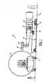
- Figure 1is a side view of a fiber placement machine of the invention
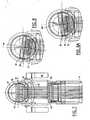
- Figure 2is a perspective view of the forearm, wrist and fiber laying head of the tape laying machine shown in figure 1 ;
- Figure 3is a perspective phantom view of the forearm, wrist and fiber laying head of the fiber placement machine of figure 1 showing the routing of the fiber band;
- Figure 4is a side view of the forearm, wrist and fiber laying head of the fiber placement machine of figure 1 ;
- Figure 5is a section taken substantially along the line 5-5 of figure 4 looking in the direction of the arrows;
- Figures 6 and 6Aare sections similar to figure 5 but showing the pitch housing in different yaw angles
- Figure 9is a section taken substantially along the line 9-9 of figure 4 looking in the direction of the arrows.
- a fiber placement machine 10 of the inventioncomprises a pair of parallel carriage rails 12 mounted on a base 14 which in the case of large machines is generally a factory floor.
- a carriage 16is slideably mounted on carriage rails 12 for movement parallel to a tool or form F, conventionally referred to as movement along a z axis or in a z direction in a Cartesian coordinate system that determines location with respect to base 14 primarily.
- Carriage 16in turn carries a pair of parallel cross slide rails 18 upon which is mounted a cross slide 20 for movement toward and away from the tool or form T, conventionally referred to as movement along an x axis or in an x direction in the location Cartesian coordinate system.
- Cross slide 20carries a creel 22 and a tilt-type forearm 24.
- Forearm 24is pivotally attached to cross slide 20 by a pivot 21 at one end so that the free end of forearm 24 moves vertically with respect to cross slide 20, the vertical movement conventionally referred to as movement along a y axis or in a y direction in the location Cartesian coordinate system.
- Carriage 16, cross slide 20 and forearm 24provide a general global position location for the end of the forearm 24. Other global positioning systems can be used such as x, y and z slides where forearm 24 typically is attached to a y-slide or a z slide.
- a fiber band type of fiber laying head 26is attached to the end of forearm 24 by a "wrist" 28 that generally provides orientation of fiber laying head 26 with respect to the end of forearm 24.
- Wrist 28provides three degrees of freedom for fiber laying head 26 by providing yaw, pitch and roll movements of fiber laying head 26 with respect to the end of forearm 24.
- the fiber delivery system of the machine 10 associated with the wristprovides a high dexterity that twists the fiber band at least three times as more fully explained below.
- yaw bracket 30comprising a yaw sleeve 32 that rotates inside a hollow annular yaw housing 34 that is attached to the end of forearm 24.
- Yaw bracket 30has a yaw yoke 36 at the top of yaw sleeve 32.
- the pitch movement (rotation about a lateral horizontal or z axis of the orientation Cartesian coordinate system) of fiber laying head 26is provided by a pitch housing 38 that is pivotally attached to the yaw yoke 36 by a pitch housing yoke 40 that is secured to pitch housing 38.
- Yaw yoke 36 and pitch housing yoke 40are pivotally interconnected by pivot 41.
- the roll movement (rotation about a longitudinal horizontal or x axis of the orientation Cartesian coordinate system) of fiber laying head 26is provided by a head bracket 42 that comprises a head sleeve 44 that rotates in pitch housing 38.
- Roll movement of fiber laying head 26is enhanced by a rear roller bracket 45 that also rotates in pitch housing 38 as explained below.
- Rotation of rear roller bracket 45 in pitch housing 38is coordinated with rotation of fiber laying head 26 in pitch housing 38 as explained below.
- Fiber laying head 26carries a compaction roller 46 that lays several tows T of a fiber band FB that originate at creel 22 onto the tool or form F.
- compaction roller 46moves with six degrees of freedom to wrap the fiber band FB against the tool or form F.
- Compaction roller 46moves in x, y and z directions in a first primarily location Cartesian coordinate system with respect to the base 14 along with carriage 16, cross slide 20 and forearm 24.
- Compaction roller 46also yaws, pitches and rolls, that is, pivots about x, y and z axes in a second primarily orientation Cartesian coordinate system with respect to the end of forearm 24 although some relocation is involved unavoidably.
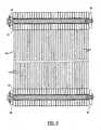
- creel 22produces the fiber band FB that is shown in detail in figure 9 .
- fiber band FBcomprises a plurality of parallel, individual fiber tows T, (for example, tows of preimpregnated carbon fiber or other prepreg materials) that are spaced apart.
- the several tows T of fiber band FB from several drums of creel 22,are trained over a fixed creel redirect roller 48.
- the tows T of fiber band FBproceed down through a hollow portion of forearm 24 to redirect roller 50 ( figure 3 ) which is located collinear with and situated between the pivot bearings of tiltable forearm 24.
- the tows T of fiber band FBare trained under redirect roller 50 and proceed beneath the tiltable forearm to its free end where tows T are trained under a fixed yaw axis redirect roller 51.
- Redirect roller 51redirects tows T of fiber band FB through yaw housing 34 in a vertical or Y direction.
- Redirect rollers 48, 50 and 51all rotate about axes parallel to Z-axis in the first Cartesian system that determines global positioning of the end of forearm 24.
- the distances between the axes of rollers 48 and 50 and between the axes of rollers 50 and 51preferably remain constant.
- the association of the fiber delivery system with wrist 28begins at the fixed forearm or yaw axis redirect roller 51 ( figures 3 and 4 ).
- fiber band FBthen continues rearward to a servoed redirect roller 54 at the rear end of pitch housing 38 ( figures 3 and 4 ).
- the servoed redirect roller 54rotates in bearings carried by the rear roller bracket 45.
- Fiber band FBis trained around servoed redirect roller 54 and then proceeds forward to at least one intermediate redirect roller.
- Each of the redirect rollers 56 and 57is sized to accommodate half of the total number of tows T comprising tow band FB and is located at approximately an equal distance from redirect roller 54.
- Redirect rollers 56 and 57are offset vertically from one another, approximately equidistant from the center of roll rotation and rotate together.
- the tows T of tow band FBare divided so that the even-number tows Te are directed to the upper redirect roller 56 and the odd-number tows To are directed to the lower redirect roller 57.
- the servoed redirect roller 54being rotatable on the rear roller bracket 45, rotates on an axis that rotates about a roll axis with respect to the pitch housing 38 in an imaginary plane perpendicular to the roll axis while the intermediate redirect rollers 56 and 57 being rotatable with the head bracket 44, pivot on respective parallel axes that rotate about a second roll axis in a second imaginary plane perpendicular to the second roll axis with respect to the pitch housing 38.
- the first and second roll axespreferably coincide with the longitudinal axis of pitch housing 38 but may be parallel to the housing and/or each other.
- the pitch axis redirect roller 52rotates on an axis that is always fixed in an imaginary plane that is perpendicular to the first and second roll axes.
- This arrangementprovides the second and third twists of fiber band FB and enhances the roll capability of fiber laying head 26 in pitch housing 38 by providing two twists that is, the second and third twists of fiber band FB between pitch axis redirect roller 52 and intermediate redirect rollers 56 and 57.
- the second twist that occurs between pitch axis redirect roller 52 and servoed redirect roller 54provides a first component of the "total roll twist" of the fiber band FB with the servo that controls rotation of the rear roller bracket 45 preferably programmed to provide about 35 % of the total roll twist.
- the third twist that occurs between the servoed redirect roller 54 and intermediate head redirect rollers 56 and 57provide the second component of the total roll twist or about 65% of the total roll twist.
- the 35-65 arrangement which divides the roll twist into two componentsallows the fiber laying head 26 to roll as much as plus or minus 155 degrees with respect to the pitch housing 38 while maintaining separation of the tows T in fiber band FB.
- Figure 7shows no roll twist while figure 8 shows a first positive roll twist between pitch axis redirect roller 52 and servoed redirect roller 54 and a second positive roll twist between servoed redirect roller 54 and head redirect roller 56.
- Figure 8Ashows the two roll twists in the negative direction.
- the even number tows Te of fiber band FBproceed down and forward from redirect roller 56 to an upper head redirect roller 58 and the odd-number tows To proceed down and forward from redirect roller 57 to a lower head redirect roller 60 ( figures 3 and 4 ).
- the use of two intermediate redirect rollers 56 and 57 rather than oneaccommodates wider fiber bands while reducing the distance required between the intermediate redirect rollers and the head redirect rollers 58 and 60.
- the fiber band FBwraps around the servoed redirect roller 54 and reverses direction. This is the preferred arrangement because it reduces the length of the pitch housing 38. However it is possible arrange the pitch axis redirect roller 52 and the intermediate head redirect roller 56 longitudinally with the servoed redirect roller 54 midway between rollers 52 and redirect rollers 56 and 57.
- the fiber laying machine 10 described aboveuses a single twist of the fiber band FB for the total yaw twist between yaw axis redirect roller 51 and pitch axis redirect roller 52.
- Such a multiple yaw twistincreases the yaw capacity of the fiber band FB while maintaining separation of the taws T if more yaw is needed to meet the dexterity requirements of a particular fiber laying machine.
- the multiple yaw twistcan then be used in combination with a single roll twist or the multiple roll twist of the fiber band FB described above. In any event, the separation of the tows T of the fiber band FG is easily maintained for pitch changes because the fiber band FB is not twisted by a pitch change. Consequently there is not any need for multiple pitch changes.
Landscapes
- Engineering & Computer Science (AREA)
- Chemical & Material Sciences (AREA)
- Composite Materials (AREA)
- Mechanical Engineering (AREA)
- Robotics (AREA)
- Moulding By Coating Moulds (AREA)
- Yarns And Mechanical Finishing Of Yarns Or Ropes (AREA)
- Nonwoven Fabrics (AREA)
- Warping, Beaming, Or Leasing (AREA)
Abstract
Description
- This invention relates to a fiber placement machine and more particularly to a fiber placement machine having a fiber delivery system associated with a wrist of a robotic manipulator.
- The dexterity of a robotic manipulator has been defined as the ability of a manipulator to access a point in a workspace from different directions and orientations. Numerically controlled machines generally require an end effector of the manipulator to follow a specified trajectory. This trajectory requires the end effector to visit various points in Cartesian space from arbitrary directions which requires the manipulator to have six degrees of freedom, three for position and three for orientation.
- In a fiber placement machine, the position of the end effector is generally provided by two slides and a forearm that either pivots or slides while the orientation of the end effector is provided by a wrist that connects a head carrying the end effector to the end of the forearm. Positioning of the head and end effector in a fiber placement machine is not difficult. However, orientation of the end effector carried by the head is difficult because the end effector that applies the fiber to a tool or form has a substantial width so that the band of fibers is twisted as it travels from the forearm to the head via the wrist. Because of this phenomenon, existing fiber placement machines have limited dexterity. This is particularly true in a fiber placement machine that lays a fiber band of tows that must be kept separate as they travel from the forearm to the head.
U.S. Patent 4,872,619 granted to Milo M. Vaniglia October 31, 1989 discloses a redirect apparatus of a fiber placement machine having a fiber placement head 25 that is attached to a forearm 14 by a wrist 15. The wrist 15 is a serial roll wrist that is disclosed inU.S. Patent 4,068,536 granted to Theodore Hahn Stackhouse January 17, 1978 . A fiber band of tows is delivered from acreel assembly 24 to the fiber placement head 25 via a grooved roller 29 and tworedirect rollers 30. Redirectrollers 30 are mounted on casters supported on a stationary creel bracket 31 and anoutboard support bracket 32 of fiber placement head 25 respectively. The fiber band of tows is twisted between the grooved roller 29 and the firstredirect roller 30 supported on the stationary creel bracket 31 and again between the tworedirect rollers 30. Theredirect rollers 30 may be part of assemblies 38a, 38b that include a servo-motor 403 to provide positive controlled movement to the roller assembly. See alsoU.S. Patent 4,877,193 granted to Milo M. Vaniglia October 31, 1989 andU.S. Patent 4,943,338 granted to Jerry B. Wisbey et al. July 24, 1990 .- This arrangement has a relatively low dexterity primarily because the fiber band of tows is offset from the centers of rotation of each of the wrist axes. This offset causes the fiber band of tows to orbit the center of rotation rather than merely to twist about it, thereby increasing the angle by which the fiber band of tows deviates from perfect perpendicularity with the axis of rotation of the redirect rollers. Additionally, this arrangement requires that all three degrees of freedom through which the fiber placement head can be oriented must be accommodated by the relative position of redirect rollers 30 (mounted on stationary creel bracket 31) and redirect rollers 30 (mounted on
outboard support bracket 32 on the fiber placement head 25). These two conditions together limit the range through which the wrist can be oriented without applying excessive side angle to the fiber band of tows. It can be seen that the greater the offset of the fiber band of tows from the centers of rotation, the more limited the range of orientation of the wrist will be. U.S. Patent 5,022,952 granted to Milo M. Vaniglia June 11, 1991 discloses another arrangement for a fiber placement machine comprising a tiltable forearm or housing 70 that has a fiber placement head 130 attached to a rotatable arm 72 by a roll bend roll type of robotic wrist 128. A fiber band of tows 11 is delivered from a creel assembly carried by the tiltable housing 70 via a fixed position roller 136 and two tape redirect rollers 138 and 140 of the same type that are discussed above in connection withU.S. Patent 4,872,619 granted to Milo M. Vaniglia October 31, 1989 . As indicated above, the fiber band of tows 11 is twisted between the fixed position roller 136 and the first redirect roller 138 supported on the tiltable housing 70 and again between the two redirect rollers 138 and 140. As above, the redirect rollers 138 and 140 may be part of assemblies that include a servo-motor to provide positive controlled movement to the roller assembly.- While this arrangement has been used successfully for many years this arrangement also has a relatively low dexterity primarily because the fiber band of tows is offset from the centers of rotation of each of the wrist axes. This offset causes the fiber band of tows to orbit the center of rotation rather than merely to twist about it, thereby increasing the angle by which the fiber band of tows deviates from perfect perpendicularity with the axis of rotation of the redirect rollers. Additionally, this arrangement requires that all three degrees of freedom through which the fiber placement head can be oriented must be accommodated by the relative position of redirect rollers (mounted on stationary creel bracket) and redirect rollers (mounted on outboard support bracket on the fiber placement head). These two conditions together limit the range through which the wrist can be oriented without applying excessive side angle to the fiber band of tows. It can be seen that the greater the offset of the fiber band of tows from the centers of rotation, the more limited the range of orientation of the wrist will be.
U.S. Patent 5,110,395 granted to Milo M. Vaniglia May 5, 1992 discloses afiber placement head 12 that has upper and lower idler rollers 92 and 94 that separate every other tow between a redirect roller 90 and a compaction shoe 104.U.S. Patent 5,239,457 granted to Richard L. Steidle et al August 24, 1993 discloses a redirect roller control for a fiber placement machine that controls the swivel angles of the two redirect rollers that are disclosed in the fiber placement machines described above in connection withU.S. Patent 4,872,619 granted to Milo M. Vaniglia October 31, 1989 andU.S. Patent 5,022,952 granted to Milo M. Vaniglia June 11, 1991 . [0009A] U.S. patent application Publication No.US 2005/0006521 discloses a fiber redirect system that includes a wrist that provides movement about yaw, pitch and roll axis. The system has three sets of redirect rollers 172A/172B; 180A/180B; and 188A/188B. Redirect rollers 172A/172B are part of a pitch redirect mechanism. Redirect rollers 180A/180B are part of a yaw redirect mechanism. Redirect rollers 188A/188B are part of a roll redirect mechanism. The dexterity of this fiber redirect mechanism is limited because the multiple tow bands can be twisted only once between the redirect rollers 172A/172B and the redirect rollers 180A/180B and only once between the redirect rollers 180A/180B and the redirect rollers 188A/188B.- This invention provides a fiber placement machine having a fiber delivery system that provides high dexterity so that the fiber can be laid on highly contoured surfaces such as, for example, domes and tip-to-tip wings.
- The fiber placement machine of the invention is characterized by a fiber delivery system in which the band of fibers is twisted in two stages about a yaw axis or a roll axis.
- In a preferred embodiment, the band of fibers is twisted three times between a fixed forearm redirect roller and a compaction roller of the head that applies the fiber to a tool or form.
- The invention is particularly advantageous in a fiber placement machine that lays a fiber band of tows that must be kept separate during travel.
Figure 1 is a side view of a fiber placement machine of the invention;Figure 2 is a perspective view of the forearm, wrist and fiber laying head of the tape laying machine shown infigure 1 ;Figure 3 is a perspective phantom view of the forearm, wrist and fiber laying head of the fiber placement machine offigure 1 showing the routing of the fiber band;Figure 4 is a side view of the forearm, wrist and fiber laying head of the fiber placement machine offigure 1 ;Figure 5 is a section taken substantially along the line 5-5 offigure 4 looking in the direction of the arrows;Figures 6 and 6A are sections similar tofigure 5 but showing the pitch housing in different yaw angles;Figure 7 is a section taken substantially along the line 7-7 offigure 4 looking in the direction of the arrows;Figures 8 and 8A are sections similar tofigure 7 but showing the head bracket and the rear roller brackets in different roll angles; andFigure 9 is a section taken substantially along the line 9-9 offigure 4 looking in the direction of the arrows.- Referring now to
figure 1 , afiber placement machine 10 of the invention comprises a pair ofparallel carriage rails 12 mounted on a base 14 which in the case of large machines is generally a factory floor. Acarriage 16 is slideably mounted oncarriage rails 12 for movement parallel to a tool or form F, conventionally referred to as movement along a z axis or in a z direction in a Cartesian coordinate system that determines location with respect to base 14 primarily. Carriage 16 in turn carries a pair of parallelcross slide rails 18 upon which is mounted across slide 20 for movement toward and away from the tool or form T, conventionally referred to as movement along an x axis or in an x direction in the location Cartesian coordinate system.Cross slide 20 carries acreel 22 and a tilt-type forearm 24. Forearm 24 is pivotally attached to crossslide 20 by apivot 21 at one end so that the free end offorearm 24 moves vertically with respect tocross slide 20, the vertical movement conventionally referred to as movement along a y axis or in a y direction in the location Cartesian coordinate system. Carriage 16,cross slide 20 and forearm 24 provide a general global position location for the end of theforearm 24. Other global positioning systems can be used such as x, y and z slides whereforearm 24 typically is attached to a y-slide or a z slide.- A fiber band type of
fiber laying head 26 is attached to the end offorearm 24 by a "wrist" 28 that generally provides orientation offiber laying head 26 with respect to the end offorearm 24.Wrist 28 provides three degrees of freedom forfiber laying head 26 by providing yaw, pitch and roll movements offiber laying head 26 with respect to the end offorearm 24. As indicated in the introduction, the fiber delivery system of themachine 10 associated with the wrist provides a high dexterity that twists the fiber band at least three times as more fully explained below. - Referring now to
figures 2 and3 , the yaw movement (rotation about a vertical or y axis of a second orientation Cartesian coordinate system that determines orientation with respect to the end offorearm 24 primarily) offiber laying head 26 is provided by ayaw bracket 30 comprising ayaw sleeve 32 that rotates inside a hollowannular yaw housing 34 that is attached to the end offorearm 24.Yaw bracket 30 has ayaw yoke 36 at the top ofyaw sleeve 32. - The pitch movement (rotation about a lateral horizontal or z axis of the orientation Cartesian coordinate system) of
fiber laying head 26 is provided by apitch housing 38 that is pivotally attached to theyaw yoke 36 by apitch housing yoke 40 that is secured to pitchhousing 38.Yaw yoke 36 and pitchhousing yoke 40 are pivotally interconnected bypivot 41. - The roll movement (rotation about a longitudinal horizontal or x axis of the orientation Cartesian coordinate system) of
fiber laying head 26 is provided by ahead bracket 42 that comprises ahead sleeve 44 that rotates inpitch housing 38. Roll movement offiber laying head 26 is enhanced by arear roller bracket 45 that also rotates inpitch housing 38 as explained below. Rotation ofrear roller bracket 45 inpitch housing 38 is coordinated with rotation offiber laying head 26 inpitch housing 38 as explained below. Fiber laying head 26 carries acompaction roller 46 that lays several tows T of a fiber band FB that originate atcreel 22 onto the tool or form F. During normal operation,compaction roller 46 moves with six degrees of freedom to wrap the fiber band FB against the tool or formF. Compaction roller 46 moves in x, y and z directions in a first primarily location Cartesian coordinate system with respect to the base 14 along withcarriage 16,cross slide 20 andforearm 24.Compaction roller 46 also yaws, pitches and rolls, that is, pivots about x, y and z axes in a second primarily orientation Cartesian coordinate system with respect to the end offorearm 24 although some relocation is involved unavoidably.- The structure and operation of a creel is well known. For instance, see
U.S. Patent 4,872,619 discussed above. Consequentlycreel 22 need not be described in detail. Suffice it to say thatcreel 22 produces the fiber band FB that is shown in detail infigure 9 . Referring momentarily tofigure 9 , fiber band FB comprises a plurality of parallel, individual fiber tows T, (for example, tows of preimpregnated carbon fiber or other prepreg materials) that are spaced apart. - Referring now to
figures 1 ,2 ,3 and4 , several rollers are provided betweenfiber laying head 26 andcreel 22 so that the sticky tows T of the fiber band FB do not touch each other as fiber band FB twists and turns betweencreel 22 andfiber laying head 26. The rollers are preferably of the type described inU.S. Patent 4,877,193 and may include guides disclosed inU.S. Patent 5,273,614 . However, any suitable type of roller may be used. - Starting at creel 22 (
figure 1 ), the several tows T of fiber band FB from several drums ofcreel 22, are trained over a fixedcreel redirect roller 48. Fromredirect roller 48 the tows T of fiber band FB proceed down through a hollow portion offorearm 24 to redirect roller 50 (figure 3 ) which is located collinear with and situated between the pivot bearings oftiltable forearm 24. The tows T of fiber band FB are trained underredirect roller 50 and proceed beneath the tiltable forearm to its free end where tows T are trained under a fixed yawaxis redirect roller 51.Redirect roller 51 redirects tows T of fiber band FB throughyaw housing 34 in a vertical or Y direction.Redirect rollers forearm 24. - The distances between the axes of
rollers rollers wrist 28 begins at the fixed forearm or yaw axis redirect roller 51 (figures 3 and4 ). - From the yaw
axis redirect roller 51, the tows T of fiber band FB then proceed up and wrap over a pitchaxis redirect roller 52 that rotates in bearings carried by theyaw bracket yoke 36 for rotation about a vertical yaw axis in the second orientation Cartesian coordinate system that determines the orientation ofhead 26 with respect to the end offorearm 24. The first twist of fiber band FB occurs betweenredirect roller 51 and pitchaxis redirect roller 52. By way of example, in a known machine, theyaw bracket yoke 36 can rotate as much as plus or minus 95 degrees while maintaining separation of the tows T in fiber band FB.Figure 5 shows no yaw twist at the yaw axis whilefigures 6 and 6A show positive and negative yaw twist respectively. - From the pitch
axis redirect roller 52, fiber band FB then continues rearward to aservoed redirect roller 54 at the rear end of pitch housing 38 (figures 3 and4 ). Theservoed redirect roller 54 rotates in bearings carried by therear roller bracket 45. Fiber band FB is trained aroundservoed redirect roller 54 and then proceeds forward to at least one intermediate redirect roller. However, there are preferably twointermediate redirect rollers head bracket 44 and rotating in bearings carried by thepitch housing 38. Each of theredirect rollers redirect roller 54.Redirect rollers upper redirect roller 56 and the odd-number tows To are directed to thelower redirect roller 57. Theservoed redirect roller 54, being rotatable on therear roller bracket 45, rotates on an axis that rotates about a roll axis with respect to thepitch housing 38 in an imaginary plane perpendicular to the roll axis while theintermediate redirect rollers head bracket 44, pivot on respective parallel axes that rotate about a second roll axis in a second imaginary plane perpendicular to the second roll axis with respect to thepitch housing 38. The first and second roll axes preferably coincide with the longitudinal axis ofpitch housing 38 but may be parallel to the housing and/or each other. The pitchaxis redirect roller 52 rotates on an axis that is always fixed in an imaginary plane that is perpendicular to the first and second roll axes. This arrangement provides the second and third twists of fiber band FB and enhances the roll capability offiber laying head 26 inpitch housing 38 by providing two twists that is, the second and third twists of fiber band FB between pitchaxis redirect roller 52 andintermediate redirect rollers - The second twist that occurs between pitch
axis redirect roller 52 andservoed redirect roller 54 provides a first component of the "total roll twist" of the fiber band FB with the servo that controls rotation of therear roller bracket 45 preferably programmed to provide about 35 % of the total roll twist. The third twist that occurs between theservoed redirect roller 54 and intermediatehead redirect rollers fiber laying head 26 to roll as much as plus or minus 155 degrees with respect to thepitch housing 38 while maintaining separation of the tows T in fiber band FB. Figure 7 shows no roll twist whilefigure 8 shows a first positive roll twist between pitchaxis redirect roller 52 andservoed redirect roller 54 and a second positive roll twist betweenservoed redirect roller 54 and head redirectroller 56.Figure 8A shows the two roll twists in the negative direction.- The even number tows Te of fiber band FB proceed down and forward from
redirect roller 56 to an upper head redirectroller 58 and the odd-number tows To proceed down and forward fromredirect roller 57 to a lower head redirect roller 60 (figures 3 and4 ). The use of twointermediate redirect rollers head redirect rollers - In the
fiber laying machine 10 described above, the fiber band FB wraps around theservoed redirect roller 54 and reverses direction. This is the preferred arrangement because it reduces the length of thepitch housing 38. However it is possible arrange the pitchaxis redirect roller 52 and the intermediatehead redirect roller 56 longitudinally with theservoed redirect roller 54 midway betweenrollers 52 and redirectrollers - The
fiber laying machine 10 described above uses a single twist of the fiber band FB for the total yaw twist between yawaxis redirect roller 51 and pitchaxis redirect roller 52. However, it is also possible to divide the total yaw twist into two components by providing another roller that rotates on an axis that rotates with respect to theyaw axis housing 34. Such a multiple yaw twist increases the yaw capacity of the fiber band FB while maintaining separation of the taws T if more yaw is needed to meet the dexterity requirements of a particular fiber laying machine. The multiple yaw twist can then be used in combination with a single roll twist or the multiple roll twist of the fiber band FB described above. In any event, the separation of the tows T of the fiber band FG is easily maintained for pitch changes because the fiber band FB is not twisted by a pitch change. Consequently there is not any need for multiple pitch changes.
Claims (9)
- A fiber placement machine having a creel (22) that supplies a fiber band to a presser member (46) that applies the fiber band to a tool or form, the presser member being part of a head (26) that is attached to the creel of the machine by a wrist (28) that provides movement about yaw, pitch and roll axes relative to the creel, the fiber band being supplied by a fiber band delivery system that is associated with the wrist (28) and that ischaracterized by a capability to twist the fiber band in two stages about one of the yaw axis or the roll axis.
- The fiber placement machine of claim 1 wherein the head (26) comprises a housing (38),
a second member (44) for receiving the fiber band from the creel and delivering the fiber band to the presser member, the second member being rotatably mounted to the housing for rotation about a longitudinal axis, and
means for twisting the fiber band in a longitudinal direction of the fiber band in stages comprising first, second and third redirect rollers (52, 54 and 56/57) for changing the direction and orientation of the fiber band as the fiber band travels from the creel to the presser member,
the first, second and third redirect rollers being rotatable about respective first, second and third axes that are located in at least two parallel planes that are perpendicular to the longitudinal axis of the second member,
the first axis being fixed with respect to the housing (38),
the second axis being rotatable with respect to the housing (38) and with respect to the second member (44), and
the third axis being fixed with respect to the second member. - The fiber placement machine of claim 2 wherein the third redirect roller is split into two parallel split rollers (56 and 57) and the third axis is split into two parallel axis for the respective parallel split rollers of the third roller.
- The fiber placement machine of claim 2 wherein the housing (38) tilts on a sleeve (32) that rotates in a second housing (34), wherein the first redirect roller (52) is at one end of the second housing (34), and wherein the fiber laying machine includes a fourth redirect roller (51) at an opposite end of the second housing for twisting the fiber band between the fourth redirect roller and the first redirect roller.
- The fiber placement machine of claim 2 wherein the first, second and third axes are located in three parallel planes.
- The fiber placement machine of claim 2 wherein the second axis is spaced longitudinally from the first axis and the third axis in a same direction.
- The fiber placement machine as defined in claim 2 wherein the second axis of the second redirect roller is rotated less than the third axis of the third redirect roller.
- The fiber placement machine as defined in claim 2 wherein the presser member (46) is part of a fiber laying head (26) that is rotatably mounted to the housing (38) via the second member (44) that is a sleeve that rotates in the housing (38).
- The fiber placement machine as defined in claim 8characterized by
a forearm having an end that moves with three degrees of freedom, and wherein the fiber laying head (26) is attached to the end of the forearm by a wrist that orients the head with three degrees of freedom with respect to the end of the forearm and wherein the second redirect roller (54) is a servoed redirect roller, the rotation of the servoed redirect roller (54) being coordinated with the rotation of the third redirect roller (56/57).
Applications Claiming Priority (1)
| Application Number | Priority Date | Filing Date | Title |
|---|---|---|---|
| US11/120,722US7353853B2 (en) | 2005-05-03 | 2005-05-03 | Fiber placement machine |
Publications (2)
| Publication Number | Publication Date |
|---|---|
| EP1719610A1 EP1719610A1 (en) | 2006-11-08 |
| EP1719610B1true EP1719610B1 (en) | 2008-10-29 |
Family
ID=36587159
Family Applications (1)
| Application Number | Title | Priority Date | Filing Date |
|---|---|---|---|
| EP06008657AActiveEP1719610B1 (en) | 2005-05-03 | 2006-04-26 | Fibre placement machine |
Country Status (6)
| Country | Link |
|---|---|
| US (1) | US7353853B2 (en) |
| EP (1) | EP1719610B1 (en) |
| JP (1) | JP4935974B2 (en) |
| AT (1) | ATE412508T1 (en) |
| DE (1) | DE602006003369D1 (en) |
| ES (1) | ES2319810T3 (en) |
Families Citing this family (16)
| Publication number | Priority date | Publication date | Assignee | Title |
|---|---|---|---|---|
| ES2337285T3 (en) | 2005-08-25 | 2010-04-22 | Ingersoll Machine Tools, Inc. | COMPACT FIBER PLACEMENT DEVICE. |
| US7516944B2 (en)* | 2006-04-18 | 2009-04-14 | Cincinnati Machine, Llc | Swiveling and tilting roller axis for web guiding in a fiber placement machine |
| US8028736B2 (en)* | 2006-08-25 | 2011-10-04 | Ocv Intellectual Capital, Llc | System for forming reinforcement layers having cross-directionally oriented fibers |
| US20100200168A1 (en)* | 2009-02-06 | 2010-08-12 | Ingersoll Machine Tools, Inc. | Fiber delivery apparatus and system having a creel and fiber placement head sans fiber redirect |
| US20110117231A1 (en)* | 2009-11-19 | 2011-05-19 | General Electric Company | Fiber placement system and method with inline infusion and cooling |
| US8954180B2 (en) | 2010-08-06 | 2015-02-10 | Ingersoll Machine Tools, Inc. | Manufacturing process and apparatus having an interchangeable machine tool head with integrated control |
| US8534338B2 (en) | 2010-10-15 | 2013-09-17 | Ingersoll Machine Tools, Inc. | Fiber delivery apparatus and system having a creel and fiber placement head with polar axis of rotation |
| US8613302B2 (en) | 2011-03-02 | 2013-12-24 | Fives Machining Systems, Inc. | Reversing fiber placement head |
| DE102011001835A1 (en)* | 2011-04-06 | 2012-10-11 | Fraunhofer-Gesellschaft zur Förderung der angewandten Forschung e.V. | Method and device for processing a strip |
| US8903311B1 (en) | 2011-08-16 | 2014-12-02 | 5Me Ip, Llc | Method of signal transmission using fiber composite sandwich panel |
| US8684720B2 (en) | 2011-12-05 | 2014-04-01 | Fives Machining Systems, Inc. | Fiber delivery system for composite part manufacture |
| DE102014110909A1 (en)* | 2014-07-31 | 2016-02-04 | Deutsches Zentrum für Luft- und Raumfahrt e.V. | Fiber laying device |
| US9545759B2 (en) | 2015-01-30 | 2017-01-17 | CGTech | Automated fiber placement with course trajectory compensation |
| US10059067B2 (en)* | 2016-01-18 | 2018-08-28 | Fives Machining Systems, Inc. | Small 4-axis fiber placement machine |
| US10449710B2 (en)* | 2017-02-17 | 2019-10-22 | Thermwood Corporation | Methods and apparatus for compressing material during additive manufacturing |
| US11040512B2 (en)* | 2017-11-08 | 2021-06-22 | Northrop Grumman Systems Corporation | Composite structures, forming apparatuses and related systems and methods |
Family Cites Families (18)
| Publication number | Priority date | Publication date | Assignee | Title |
|---|---|---|---|---|
| US4068536A (en) | 1976-12-23 | 1978-01-17 | Cincinnati Milacron Inc. | Manipulator |
| US5022952A (en) | 1985-12-13 | 1991-06-11 | Cincinnati Milacron Inc. | Fiber placement machine |
| US4907754A (en) | 1985-12-13 | 1990-03-13 | Cincinnati Milacron Inc. | Fiber placement machine |
| US4877193A (en) | 1988-08-25 | 1989-10-31 | Cincinnati Milacron Inc. | Redirect roller apparatus for fiber placement machine |
| DE68909351T2 (en)* | 1988-08-25 | 1994-01-13 | Cincinnati Milacron Inc | Laying device for fibers. |
| US4872619A (en) | 1988-11-02 | 1989-10-10 | Cincinnati Milacron Inc. | Serco driven redirect roller apparatus for fiber placement machine |
| US4943338A (en) | 1988-09-26 | 1990-07-24 | Cincinnati Milacron Inc. | Multi-tow fiber placement machine with full band width clamp, cut, and restart capability |
| US4869774A (en)* | 1988-09-26 | 1989-09-26 | Cincinnati Milacron Inc. | Compliant presser member for fiber placement machine |
| US5110395A (en) | 1989-12-04 | 1992-05-05 | Cincinnati Milacron Inc. | Fiber placement head |
| US5239457A (en) | 1990-07-16 | 1993-08-24 | Cincinnati Milacron Inc. | Redirect roller control for fiber placement machine |
| JP2998903B2 (en)* | 1990-11-14 | 2000-01-17 | 東京エレクトロン株式会社 | Heat treatment equipment |
| CA2057201C (en)* | 1990-12-19 | 1998-05-19 | Vernon M. Benson | Multiple axes fiber placement machine |
| CA2057222C (en)* | 1990-12-19 | 1998-05-19 | Keith G. Shupe | Fiber placement delivery system |
| US5273614A (en) | 1991-09-23 | 1993-12-28 | Cincinnati Milacron Inc. | Tow guide for redirect rollers in a fiber placement machine |
| US5454897A (en) | 1994-05-02 | 1995-10-03 | Cincinnati Milacron Inc. | Presser member for fiber laying machine |
| US6003400A (en) | 1998-05-16 | 1999-12-21 | Jason W. Rauchfuss | Robotic wrist mechanism |
| US6994324B2 (en) | 2003-05-02 | 2006-02-07 | Alliant Techsystems Inc. | Fiber redirect system, multi-axis robotic wrist and fiber placement apparatus incorporating same and related methods |
| CA2563640A1 (en) | 2004-04-21 | 2005-11-10 | Ingersoll Machine Tools, Inc. | Forming a composite structure by filament placement on a tool surface of a tablet |
- 2005
- 2005-05-03USUS11/120,722patent/US7353853B2/enactiveActive
- 2006
- 2006-04-26EPEP06008657Apatent/EP1719610B1/enactiveActive
- 2006-04-26DEDE602006003369Tpatent/DE602006003369D1/enactiveActive
- 2006-04-26ESES06008657Tpatent/ES2319810T3/enactiveActive
- 2006-04-26ATAT06008657Tpatent/ATE412508T1/ennot_activeIP Right Cessation
- 2006-05-08JPJP2006129245Apatent/JP4935974B2/ennot_activeExpired - Fee Related
Also Published As
| Publication number | Publication date |
|---|---|
| ATE412508T1 (en) | 2008-11-15 |
| US7353853B2 (en) | 2008-04-08 |
| US20060249256A1 (en) | 2006-11-09 |
| EP1719610A1 (en) | 2006-11-08 |
| ES2319810T3 (en) | 2009-05-12 |
| JP4935974B2 (en) | 2012-05-23 |
| DE602006003369D1 (en) | 2008-12-11 |
| JP2006312809A (en) | 2006-11-16 |
Similar Documents
| Publication | Publication Date | Title |
|---|---|---|
| EP1719610B1 (en) | Fibre placement machine | |
| US8758538B2 (en) | Robotic based fiber placement cell with stationary dispensing head and creel | |
| EP2305456B1 (en) | A multi-axis robotic wrist and fiber placement apparatus incorporating same and related method | |
| US4877193A (en) | Redirect roller apparatus for fiber placement machine | |
| US8210086B2 (en) | Braided reinforcement for aircraft fuselage frames and method of producing the same | |
| US5022952A (en) | Fiber placement machine | |
| EP0225563B1 (en) | Fibre delivery assembly and fibre placement machine | |
| US6112792A (en) | Fiber placement mid-span redirect | |
| US4872619A (en) | Serco driven redirect roller apparatus for fiber placement machine | |
| US11931974B2 (en) | Filament winding apparatus | |
| US12036757B2 (en) | Manipulator device having a triangular architecture and installation for manufacturing tires using such a manipulator device for placing strips | |
| EP3882189B1 (en) | Filament winding device | |
| US6753495B2 (en) | Apparatus and methods for control of a material processing device | |
| EP0355308B1 (en) | Fibre placement machine | |
| US7516944B2 (en) | Swiveling and tilting roller axis for web guiding in a fiber placement machine | |
| CN115972627A (en) | Roller exchanging device | |
| US20230286178A1 (en) | Work device |
Legal Events
| Date | Code | Title | Description |
|---|---|---|---|
| PUAI | Public reference made under article 153(3) epc to a published international application that has entered the european phase | Free format text:ORIGINAL CODE: 0009012 | |
| AK | Designated contracting states | Kind code of ref document:A1 Designated state(s):AT BE BG CH CY CZ DE DK EE ES FI FR GB GR HU IE IS IT LI LT LU LV MC NL PL PT RO SE SI SK TR | |
| AX | Request for extension of the european patent | Extension state:AL BA HR MK YU | |
| 17P | Request for examination filed | Effective date:20070426 | |
| 17Q | First examination report despatched | Effective date:20070601 | |
| AKX | Designation fees paid | Designated state(s):AT BE BG CH CY CZ DE DK EE ES FI FR GB GR HU IE IS IT LI LT LU LV MC NL PL PT RO SE SI SK TR | |
| GRAP | Despatch of communication of intention to grant a patent | Free format text:ORIGINAL CODE: EPIDOSNIGR1 | |
| GRAS | Grant fee paid | Free format text:ORIGINAL CODE: EPIDOSNIGR3 | |
| GRAA | (expected) grant | Free format text:ORIGINAL CODE: 0009210 | |
| AK | Designated contracting states | Kind code of ref document:B1 Designated state(s):AT BE BG CH CY CZ DE DK EE ES FI FR GB GR HU IE IS IT LI LT LU LV MC NL PL PT RO SE SI SK TR | |
| REG | Reference to a national code | Ref country code:GB Ref legal event code:FG4D | |
| REG | Reference to a national code | Ref country code:CH Ref legal event code:EP | |
| REG | Reference to a national code | Ref country code:IE Ref legal event code:FG4D | |
| REF | Corresponds to: | Ref document number:602006003369 Country of ref document:DE Date of ref document:20081211 Kind code of ref document:P | |
| NLV1 | Nl: lapsed or annulled due to failure to fulfill the requirements of art. 29p and 29m of the patents act | ||
| LTIE | Lt: invalidation of european patent or patent extension | Effective date:20081029 | |
| PG25 | Lapsed in a contracting state [announced via postgrant information from national office to epo] | Ref country code:BG Free format text:LAPSE BECAUSE OF FAILURE TO SUBMIT A TRANSLATION OF THE DESCRIPTION OR TO PAY THE FEE WITHIN THE PRESCRIBED TIME-LIMIT Effective date:20090129 Ref country code:AT Free format text:LAPSE BECAUSE OF FAILURE TO SUBMIT A TRANSLATION OF THE DESCRIPTION OR TO PAY THE FEE WITHIN THE PRESCRIBED TIME-LIMIT Effective date:20081029 Ref country code:LT Free format text:LAPSE BECAUSE OF FAILURE TO SUBMIT A TRANSLATION OF THE DESCRIPTION OR TO PAY THE FEE WITHIN THE PRESCRIBED TIME-LIMIT Effective date:20081029 | |
| REG | Reference to a national code | Ref country code:ES Ref legal event code:FG2A Ref document number:2319810 Country of ref document:ES Kind code of ref document:T3 | |
| PG25 | Lapsed in a contracting state [announced via postgrant information from national office to epo] | Ref country code:FI Free format text:LAPSE BECAUSE OF FAILURE TO SUBMIT A TRANSLATION OF THE DESCRIPTION OR TO PAY THE FEE WITHIN THE PRESCRIBED TIME-LIMIT Effective date:20081029 Ref country code:LV Free format text:LAPSE BECAUSE OF FAILURE TO SUBMIT A TRANSLATION OF THE DESCRIPTION OR TO PAY THE FEE WITHIN THE PRESCRIBED TIME-LIMIT Effective date:20081029 Ref country code:SI Free format text:LAPSE BECAUSE OF FAILURE TO SUBMIT A TRANSLATION OF THE DESCRIPTION OR TO PAY THE FEE WITHIN THE PRESCRIBED TIME-LIMIT Effective date:20081029 Ref country code:PT Free format text:LAPSE BECAUSE OF FAILURE TO SUBMIT A TRANSLATION OF THE DESCRIPTION OR TO PAY THE FEE WITHIN THE PRESCRIBED TIME-LIMIT Effective date:20090330 Ref country code:IS Free format text:LAPSE BECAUSE OF FAILURE TO SUBMIT A TRANSLATION OF THE DESCRIPTION OR TO PAY THE FEE WITHIN THE PRESCRIBED TIME-LIMIT Effective date:20090228 Ref country code:NL Free format text:LAPSE BECAUSE OF FAILURE TO SUBMIT A TRANSLATION OF THE DESCRIPTION OR TO PAY THE FEE WITHIN THE PRESCRIBED TIME-LIMIT Effective date:20081029 Ref country code:PL Free format text:LAPSE BECAUSE OF FAILURE TO SUBMIT A TRANSLATION OF THE DESCRIPTION OR TO PAY THE FEE WITHIN THE PRESCRIBED TIME-LIMIT Effective date:20081029 | |
| PG25 | Lapsed in a contracting state [announced via postgrant information from national office to epo] | Ref country code:RO Free format text:LAPSE BECAUSE OF FAILURE TO SUBMIT A TRANSLATION OF THE DESCRIPTION OR TO PAY THE FEE WITHIN THE PRESCRIBED TIME-LIMIT Effective date:20081029 Ref country code:EE Free format text:LAPSE BECAUSE OF FAILURE TO SUBMIT A TRANSLATION OF THE DESCRIPTION OR TO PAY THE FEE WITHIN THE PRESCRIBED TIME-LIMIT Effective date:20081029 Ref country code:DK Free format text:LAPSE BECAUSE OF FAILURE TO SUBMIT A TRANSLATION OF THE DESCRIPTION OR TO PAY THE FEE WITHIN THE PRESCRIBED TIME-LIMIT Effective date:20081029 Ref country code:BE Free format text:LAPSE BECAUSE OF FAILURE TO SUBMIT A TRANSLATION OF THE DESCRIPTION OR TO PAY THE FEE WITHIN THE PRESCRIBED TIME-LIMIT Effective date:20081029 | |
| PG25 | Lapsed in a contracting state [announced via postgrant information from national office to epo] | Ref country code:CZ Free format text:LAPSE BECAUSE OF FAILURE TO SUBMIT A TRANSLATION OF THE DESCRIPTION OR TO PAY THE FEE WITHIN THE PRESCRIBED TIME-LIMIT Effective date:20081029 Ref country code:SE Free format text:LAPSE BECAUSE OF FAILURE TO SUBMIT A TRANSLATION OF THE DESCRIPTION OR TO PAY THE FEE WITHIN THE PRESCRIBED TIME-LIMIT Effective date:20090129 | |
| PLBE | No opposition filed within time limit | Free format text:ORIGINAL CODE: 0009261 | |
| STAA | Information on the status of an ep patent application or granted ep patent | Free format text:STATUS: NO OPPOSITION FILED WITHIN TIME LIMIT | |
| PG25 | Lapsed in a contracting state [announced via postgrant information from national office to epo] | Ref country code:SK Free format text:LAPSE BECAUSE OF FAILURE TO SUBMIT A TRANSLATION OF THE DESCRIPTION OR TO PAY THE FEE WITHIN THE PRESCRIBED TIME-LIMIT Effective date:20081029 | |
| 26N | No opposition filed | Effective date:20090730 | |
| REG | Reference to a national code | Ref country code:IE Ref legal event code:MM4A | |
| PG25 | Lapsed in a contracting state [announced via postgrant information from national office to epo] | Ref country code:MC Free format text:LAPSE BECAUSE OF NON-PAYMENT OF DUE FEES Effective date:20090430 Ref country code:IE Free format text:LAPSE BECAUSE OF NON-PAYMENT OF DUE FEES Effective date:20090426 | |
| PG25 | Lapsed in a contracting state [announced via postgrant information from national office to epo] | Ref country code:GR Free format text:LAPSE BECAUSE OF FAILURE TO SUBMIT A TRANSLATION OF THE DESCRIPTION OR TO PAY THE FEE WITHIN THE PRESCRIBED TIME-LIMIT Effective date:20090130 | |
| GBPC | Gb: european patent ceased through non-payment of renewal fee | Effective date:20100426 | |
| PG25 | Lapsed in a contracting state [announced via postgrant information from national office to epo] | Ref country code:GB Free format text:LAPSE BECAUSE OF NON-PAYMENT OF DUE FEES Effective date:20100426 | |
| PG25 | Lapsed in a contracting state [announced via postgrant information from national office to epo] | Ref country code:LU Free format text:LAPSE BECAUSE OF NON-PAYMENT OF DUE FEES Effective date:20090426 | |
| PG25 | Lapsed in a contracting state [announced via postgrant information from national office to epo] | Ref country code:HU Free format text:LAPSE BECAUSE OF FAILURE TO SUBMIT A TRANSLATION OF THE DESCRIPTION OR TO PAY THE FEE WITHIN THE PRESCRIBED TIME-LIMIT Effective date:20090430 | |
| PG25 | Lapsed in a contracting state [announced via postgrant information from national office to epo] | Ref country code:TR Free format text:LAPSE BECAUSE OF FAILURE TO SUBMIT A TRANSLATION OF THE DESCRIPTION OR TO PAY THE FEE WITHIN THE PRESCRIBED TIME-LIMIT Effective date:20081029 | |
| PG25 | Lapsed in a contracting state [announced via postgrant information from national office to epo] | Ref country code:CY Free format text:LAPSE BECAUSE OF FAILURE TO SUBMIT A TRANSLATION OF THE DESCRIPTION OR TO PAY THE FEE WITHIN THE PRESCRIBED TIME-LIMIT Effective date:20081029 | |
| REG | Reference to a national code | Ref country code:CH Ref legal event code:PUE Owner name:CINCINNATI MACHINE LLC Free format text:MAGUS INTELLECTUAL PROPERTY GMBH#GRABENSTRASSE 42#6301 ZUG (CH) -TRANSFER TO- CINCINNATI MACHINE LLC#2300 LITTON LANE#HEBRON, KENTUCKY 41048 (US) | |
| PGFP | Annual fee paid to national office [announced via postgrant information from national office to epo] | Ref country code:CH Payment date:20110929 Year of fee payment:6 | |
| REG | Reference to a national code | Ref country code:CH Ref legal event code:PL | |
| PG25 | Lapsed in a contracting state [announced via postgrant information from national office to epo] | Ref country code:LI Free format text:LAPSE BECAUSE OF NON-PAYMENT OF DUE FEES Effective date:20120430 Ref country code:CH Free format text:LAPSE BECAUSE OF NON-PAYMENT OF DUE FEES Effective date:20120430 | |
| REG | Reference to a national code | Ref country code:DE Ref legal event code:R082 Ref document number:602006003369 Country of ref document:DE Representative=s name:BOEHMERT & BOEHMERT, DE | |
| REG | Reference to a national code | Ref country code:DE Ref legal event code:R082 Ref document number:602006003369 Country of ref document:DE Representative=s name:BOEHMERT & BOEHMERT, DE | |
| REG | Reference to a national code | Ref country code:DE Ref legal event code:R082 Ref document number:602006003369 Country of ref document:DE Representative=s name:BOEHMERT & BOEHMERT ANWALTSPARTNERSCHAFT MBB -, DE Effective date:20140709 Ref country code:DE Ref legal event code:R082 Ref document number:602006003369 Country of ref document:DE Representative=s name:BOEHMERT & BOEHMERT ANWALTSPARTNERSCHAFT MBB -, DE Effective date:20140716 Ref country code:DE Ref legal event code:R081 Ref document number:602006003369 Country of ref document:DE Owner name:FIVES MACHINING SYSTEMS, INC., FOND DU LAC, US Free format text:FORMER OWNER: CINCINNATI MACHINE, LLC, HEBRON, KY., US Effective date:20140716 Ref country code:DE Ref legal event code:R081 Ref document number:602006003369 Country of ref document:DE Owner name:FIVES MACHINING SYSTEMS, INC., FOND DU LAC, US Free format text:FORMER OWNER: MAGUS INTELLECTUAL PROPERTY GMBH, ZUG, CH Effective date:20140709 | |
| REG | Reference to a national code | Ref country code:FR Ref legal event code:CD Owner name:FIVES MACHINING SYSTEMS, INC., US Effective date:20140901 Ref country code:FR Ref legal event code:TP Owner name:FIVES MACHINING SYSTEMS, INC., US Effective date:20140901 | |
| REG | Reference to a national code | Ref country code:FR Ref legal event code:PLFP Year of fee payment:10 | |
| REG | Reference to a national code | Ref country code:FR Ref legal event code:PLFP Year of fee payment:11 | |
| REG | Reference to a national code | Ref country code:FR Ref legal event code:PLFP Year of fee payment:12 | |
| REG | Reference to a national code | Ref country code:FR Ref legal event code:PLFP Year of fee payment:13 | |
| PGFP | Annual fee paid to national office [announced via postgrant information from national office to epo] | Ref country code:FR Payment date:20250319 Year of fee payment:20 | |
| PGFP | Annual fee paid to national office [announced via postgrant information from national office to epo] | Ref country code:IT Payment date:20250319 Year of fee payment:20 | |
| PGFP | Annual fee paid to national office [announced via postgrant information from national office to epo] | Ref country code:DE Payment date:20250319 Year of fee payment:20 | |
| PGFP | Annual fee paid to national office [announced via postgrant information from national office to epo] | Ref country code:ES Payment date:20250502 Year of fee payment:20 |