EP1719580B1 - Laser projection system - Google Patents
Laser projection systemDownload PDFInfo
- Publication number
- EP1719580B1 EP1719580B1EP06112293AEP06112293AEP1719580B1EP 1719580 B1EP1719580 B1EP 1719580B1EP 06112293 AEP06112293 AEP 06112293AEP 06112293 AEP06112293 AEP 06112293AEP 1719580 B1EP1719580 B1EP 1719580B1
- Authority
- EP
- European Patent Office
- Prior art keywords
- laser
- metrology
- laser projector
- projector
- frame
- Prior art date
- Legal status (The legal status is an assumption and is not a legal conclusion. Google has not performed a legal analysis and makes no representation as to the accuracy of the status listed.)
- Expired - Lifetime
Links
- 230000008602contractionEffects0.000claimsdescription6
- VNWKTOKETHGBQD-UHFFFAOYSA-NmethaneChemical compoundCVNWKTOKETHGBQD-UHFFFAOYSA-N0.000claimsdescription6
- 229920000049Carbon (fiber)Polymers0.000claimsdescription5
- 239000004917carbon fiberSubstances0.000claimsdescription5
- 238000000034methodMethods0.000description23
- 238000003384imaging methodMethods0.000description18
- 230000000712assemblyEffects0.000description12
- 238000000429assemblyMethods0.000description12
- 239000002131composite materialSubstances0.000description6
- 239000000463materialSubstances0.000description5
- 230000000717retained effectEffects0.000description4
- 238000012986modificationMethods0.000description3
- 230000004048modificationEffects0.000description3
- 230000003287optical effectEffects0.000description3
- 238000010276constructionMethods0.000description2
- 238000005259measurementMethods0.000description2
- 101710163092D-lysergyl-peptide-synthetase subunit 1Proteins0.000description1
- 229920000784NomexPolymers0.000description1
- 239000004677NylonSubstances0.000description1
- XAGFODPZIPBFFR-UHFFFAOYSA-NaluminiumChemical compound[Al]XAGFODPZIPBFFR-UHFFFAOYSA-N0.000description1
- 229910052782aluminiumInorganic materials0.000description1
- 238000013459approachMethods0.000description1
- 238000012937correctionMethods0.000description1
- 238000013461designMethods0.000description1
- 238000009434installationMethods0.000description1
- 238000012423maintenanceMethods0.000description1
- 239000004763nomexSubstances0.000description1
- 229920001778nylonPolymers0.000description1
Images


Classifications
- G—PHYSICS
- G01—MEASURING; TESTING
- G01S—RADIO DIRECTION-FINDING; RADIO NAVIGATION; DETERMINING DISTANCE OR VELOCITY BY USE OF RADIO WAVES; LOCATING OR PRESENCE-DETECTING BY USE OF THE REFLECTION OR RERADIATION OF RADIO WAVES; ANALOGOUS ARRANGEMENTS USING OTHER WAVES
- G01S5/00—Position-fixing by co-ordinating two or more direction or position line determinations; Position-fixing by co-ordinating two or more distance determinations
- G01S5/16—Position-fixing by co-ordinating two or more direction or position line determinations; Position-fixing by co-ordinating two or more distance determinations using electromagnetic waves other than radio waves
- B—PERFORMING OPERATIONS; TRANSPORTING
- B25—HAND TOOLS; PORTABLE POWER-DRIVEN TOOLS; MANIPULATORS
- B25H—WORKSHOP EQUIPMENT, e.g. FOR MARKING-OUT WORK; STORAGE MEANS FOR WORKSHOPS
- B25H7/00—Marking-out or setting-out work
- G—PHYSICS
- G01—MEASURING; TESTING
- G01S—RADIO DIRECTION-FINDING; RADIO NAVIGATION; DETERMINING DISTANCE OR VELOCITY BY USE OF RADIO WAVES; LOCATING OR PRESENCE-DETECTING BY USE OF THE REFLECTION OR RERADIATION OF RADIO WAVES; ANALOGOUS ARRANGEMENTS USING OTHER WAVES
- G01S5/00—Position-fixing by co-ordinating two or more direction or position line determinations; Position-fixing by co-ordinating two or more distance determinations
- G01S5/16—Position-fixing by co-ordinating two or more direction or position line determinations; Position-fixing by co-ordinating two or more distance determinations using electromagnetic waves other than radio waves
- G01S5/163—Determination of attitude
Definitions
- This inventionrelates to a method and apparatus for projecting a laser template on a surface particularly including a method and apparatus for projecting a laser template on a surface without laser targets on the surface, or a "targetless" laser projection system and method which increases the application of laser projection systems, including projection of laser templates on larger surfaces, such as aircraft, or where laser targets on the surface would interfere with further operations or conventional laser projection systems would be impractical or impossible.
- Visible laser projection systemsare now widely used in industry to project a laser outline or "template” on a work or target surface for assembling large two or three-dimensional structures or assemblies, such as prefabricated roof trusses or aerospace composite components.
- the laser projection systemis capable of accurately producing a laser image or template at known coordinates on a work or target surface which may be planar or curvilinear.
- U.S. Patent No. 5,646,859assigned in part to the assignee of this application, discloses a method and apparatus for defining a laser template for assembling a structure, such as a prefabricated roof truss.
- the method and apparatus disclosed in this patentincludes a laser projector or a plurality of laser projectors mounted above the work surface, a plurality of laser sensors or laser targets fixed at predetermined locations on or adjacent the work surface, a computer and a sensor on the laser projector periodically or continuously scans the laser targets and the reflected light from the laser targets to the sensor of the laser projector determines the precise projection angle associated with the center of each target datum.
- the precise position and orientation of the laser projector relative to the work surface or partis then calculated by the computer.
- This spatial informationallows the laser projector to generate accurate laser templates or laser outlines of the part on the target surface.
- the laser projectormay be fixed relative to the part or work surface or for larger assemblies, a plurality of laser projectors may be used or the laser projectors may be moved relative to the work surface as disclosed in the above-referenced patent.
- the laser targets or position sensorsmay include a photo transistor, but in most applications, retroreflective laser targets are now used.
- Alignment and calibration methods similar to the aboveprovide the accuracy needed for a wide range of laser projection applications.
- a typical accuracy specificationis ⁇ 0.4mm (0.015 inches) at a 3.048m to 4.572m (10 to 15 foot) stand off distance when measured perpendicular to the laser beam.
- This approachallows good flexibility in positioning of the laser projectors because the mounting location can be arbitrarily selected so long as a sufficient number of known laser target locations are detectable within the field of view of the laser projector which, as set forth above, must be located at predetermined locations on or adjacent the target surface.
- a minimum of four laser targetsmust be located by the sensor system (laser target and sensor) to establish the position of the laser projector relative to the assembled structure or part and the work or target surface.
- the requirement for laser targets at fixed locations on or adjacent the target surfacehas limited the applications for laser projection systems.
- laser projection systemsFor example, to guide the placement of carbon fiber composite materials for aerospace structures, it is generally necessary to locate the targets on the target surface which will eventually be covered by the composite material.
- the required laser projection areamay be too large to allow placement of laser or reference targets within the field of view of the laser projectors, making accurate projection difficult.
- Another problem addressed by the laser projection systems of this inventionis laser projection or image drift, which may result from variations in temperature and humidity.
- CMMcoordinate measuring machine
- a disclosed embodiment of the laser projector system of this inventionutilizes an indoor global positioning system (GPS), such as disclosed in U.S. Patent Nos. 6,501,543 and 6,535,282 of Arc Second, Inc..
- GPSglobal positioning system
- Indoor GPS systemsare also commercially available from Arc Second, Inc.
- the laser projection systems of this inventionare not limited to indoor GPS systems and other external metrology devices may be utilized, including laser theodelite transmitter tracking devices, optical photogrametry devices, camera base systems, infrared transmitter metrology devices and other metrology tracker projection devices.
- Leica Geosystems and Northern Digitaloffer laser trackers systems for three-dimensional measurements, wherein the laser from the metrology transmitters is reflected by mirrors or a corner cube reflector (CCR) on a parallel path to a sensor on the metrology transmitters and the data from the receiver is transmitted to a computer to determine the location of the reflector.
- Such external metrology devicesgenerally include a metrology transmitter, typically a light metrology transmitter, and a plurality of metrology receivers or reflectors which are fixed at predetermined locations.
- a laser projector and frame assemblycomprising:
- the external metrology devicegenerally includes a plurality of metrology transmitters at fixed locations, typically light metrology transmitters, such as infrared laser light metrology transmitters, and a plurality of metrology receivers also at fixed locations.
- the term "metrology receivers"includes both active receivers, such as the indoor GPS receivers, and passive devices, such as mirrors or corner cube reflectors, which reflect light back to sensors on the metrology transmitters and thus both embodiments have a sensor associated with the receiver.
- a first plurality of metrology receiversare fixed relative to the target surface.
- a second plurality of metrology receiversare fixed relative to the laser projector or projectors.
- the term "fixed"means that the location is stable as required for determination of the location of the transmitters, receivers, laser targets, etc.
- the inventionmay be used to generate a signal from the external metrology device to a computer and the computer then uses the data received from the metrology device to determine the position and orientation of the laser projector relative to the target surface.
- the metrology receiversmay be connected to the computer or the data from the metrology receivers may be transmitted to the computer by a wireless system.
- the methodthen includes orienting a laser from the laser projector or projectors relative to the target surface to a project laser template on the target surface at a predetermined or defined location and orientation using the data from the computer and finally projecting the laser template on the target surface at the predetermined location and orientation with the laser projector.
- the method ofthus eliminates the requirement for laser targets on or adjacent the target surface and calibration of the laser projector relative to laser targets on or adjacent the target surface and is thus "targetless". Further, the metrology receivers do not have to be within a field of view of the laser projector or projectors.
- a preferred embodimentmay also be utilized to correct for laser projection or image drift or movement of the laser projector without the requirement for laser targets fixed at predetermined locations on or adjacent the target surface and calibration of the laser projector relative to such laser targets as described above.
- a disclosed embodimentincludes periodically or continuously projecting a laser from the laser projector on laser targets within a field of view of the laser projector. That is, rather than scanning laser targets fixed at predetermined locations relative to the target surface, the method of correcting for laser drift includes fixing laser targets relative to the projector, rather than the target surface.
- the laser targetsmay be fixed relative to the metrology receivers within a field of view of the laser projector, permitting location of the laser projector by scanning the laser targets.
- the laser projectoris supported in a frame assembly having laser targets on the frame assembly opposite the laser projector and the laser projector then periodically or continuously scans the laser target to correct for laser drift or movement of the laser projector.
- the methodincludes reflecting the laser beam from the laser targets to a sensor on the laser projector and generating a signal to a computer connected to a control which corrects for laser image drift or movement of the laser projector.
- the method of using the inventionincludes periodically scanning the laser targets on the distal open end of the frame assembly and correcting for laser image drift or movement of the laser projector.
- the laser projectormay move relative to the frame and determine its position and orientation by scanning the laser targets.
- the term "periodically”includes continuously scanning the laser targets and the laser targets may be retroreflective targets or any suitable laser target or position sensor, as disclosed for example in the above referenced U.S. Patent No. 5,646,859 .
- the "targetless" laser imaging system of this inventionmay include a plurality of metrology transmitters located at fixed locations, a laser projector or a plurality of laser projectors, a first plurality of metrology receivers or target reflectors and receivers on the metrology transmitters, as described above, at fixed locations relative to the target surface and second plurality of metrology receivers or target reflectors located at fixed locations relative to the laser projector.
- the laser imaging systemmay include a computer receiving data from the metrology receivers or sensors determining the precise location and orientation of the laser projector relative to the target surface and controlling the laser projector to project a laser template on the target surface at the predetermined or defined location and orientation.
- the laser imaging systemmay further include a plurality of laser targets at fixed locations relative to the laser projector within a field of view of the laser projector or the laser projector may be movable provided the laser targets are fixed relative to the metrology receivers and the computer then controls the laser projector to periodically scan the laser targets and compensate for laser image drift or movement of the laser projector.
- the frame assemblyalso includes laser targets opposite the laser projector, as described above, the laser targets must be spaced from the laser projector and the disclosed embodiment of the frame assembly includes strut portions interconnecting the support surface and the open distal end of the frame assembly.
- the frame assemblyis integrally formed from a material having a low co-efficient of expansion and contraction to avoid errors due to thermal expansion or contraction, such as a carbon fiber composite. Because the location and orientation of the metrology receivers or reflectors is fixed relative to the metrology receivers or the laser projector, the laser projector or projectors may be moved relative to the target surface as required by the application.
- the laser projector and frame assemblyis supported on a universal joint, permitting movement of the laser projector in at least two axes.
- the laser projectorsmay also be supported on carts or dollies for ease of placement of the laser projectors relative to the target surface.
- the target surfacemay also be moved to relative to the laser projectors.
- the laser projection systemis particularly, but not exclusively suitable for projecting a laser template on a target surface, where laser targets would interfere with subsequent operations, such as ply layup on large target surfaces, such as an aircraft body, for subsequent operations, such as the application of decals, placement of fixtures and covering the joints between the components of the target surface, such as an aircraft.
- the laser projection systemis not limited to any particular application. In such applications, however, it is desirable to fix the metrology receivers or reflectors on stanchions, such that the reflector or receiver is located above the floor for ease of reference in determining the position and orientation of the target surface.
- the receiver assemblymay be removed from the support and replaced without changing the position and orientation of the metrology receiver.
- the metrology receiver assemblyincludes a support stanchion adapted to be permanently affixed to a support in a workstation in a predetermined location.
- a bottom kinematic plateis fixed to the top of the support stanchion and the assembly includes a receiver support member having a top kinematic plate secured to the support member releasably attached to the bottom kinematic plate.
- one of the top and bottom kinematic platesincludes a plurality of spaced projecting portions and the other of the top and bottom kinematic plates has a plurality of spaced recesses configured to receive the spaced projecting portions to align and orient the top kinematic plate relative to the bottom kinematic plate, such that the top kinematic plate, receiver support and metrology receiver or reflector may be removed from and replaced on the support stanchion without changing the position and orientation of the metrology receiver.
- the top kinematic plateis releasably attached to the bottom kinematic plate by a magnet, such that the top kinematic plate, receiver support and metrology receiver may be easily removed from and replaced on the support stanchion without changing the position and orientation of the assembly.
- the laser projection systemincludes metrology receivers having a support adapted to be fixed at a predetermined location and orientation, as described above.
- the supportincludes a cup-shaped enclosure mounted on the support, a first metrology receiver adapted to receive or reflect a signal from a metrology transmitter, as described above, and a second receiver to reflect a laser, such as a spherical mounted reflector (SMR) or a corner cube reflector (CCR) or a photogrametric or retroreflective laser target, wherein the cup-shaped enclosure is configured to receive and orient one of the first metrology receivers or the CMM laser reflector receiver, such that the position and orientation of the metrology receiver may be independently determined and confirmed for accuracy as required by certain applications.
- SMRspherical mounted reflector
- CCRcorner cube reflector
- the laser projection systemmay project a laser template on a target surface which is located outside the field of view of the laser projector.
- the laser templateis projected on a mirrored surface to project the laser template on a target surface located outside the field of view of the laser projector.
- the mirrormay be supported by a frame assembly having laser targets as described above. Where the laser projector and mirror assembly is utilized in a targetless laser projection system, the mirror frame may also include metrology receivers or reflectors, as described above.
- the laser projector of the laser projector system of this inventionmay be mounted on other conveyances, such as a lift depending upon the application.
- the laser projector and frame assemblyis mounted on a platform which may also be used by personnel for subsequent operations and the platform is mounted on a piston telescopically received in a vertical hydraulic or pneumatic cylinder attached to the roof or ceiling of a workstation, permitting the platform to be moved vertically for applications requiring vertical movement.
- the laser projection system of this inventionmay be utilized with any metrology device, including but not limited to indoor GPS metrology and laser tracking devices as described above.
- the computer used in the method of this invention and the laser projection or imaging systemsmay also be a plurality of computers.
- Figure 1is a partially schematic side elevation of the basic components of a targetless laser projection system of this invention and method of projecting a laser template on a target surface;
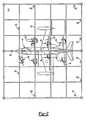
- Figure 2is a top view of an embodiment of a workstation for projecting a laser template on an aircraft for subsequent operations;
- Figure 3is a side view of Figure 1 ;
- Figure 4is an end view of Figures 2 and 3 ;
- Figure 5is a front partial view of Figures 2 to 4 with upper portions of the roof assembly removed for a clearer understanding of Figures 2 to 4 ;
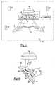
- Figure 6is a side perspective view of one embodiment of a laser projector and frame assembly of this invention shown in Figures 2 to 5 ;
- Figure 7is a side perspective view of the laser projector and frame assembly shown in Figure 6 with the frame tilted on the universal support;
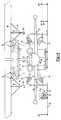
- Figure 8is a side partially cross-sectioned side view of one embodiment of a vector bar metrology sensor or receiver and removable rigid connector and support assembly suitable for attachment of the metrology receiver to an aircraft;
- Figure 9is an exploded view of an alternative embodiment of a vector bar metrology receiver and removable rigid connector and support assembly
- Figure 10is a side perspective view of the assembly shown in Figure 9 following assembly to the target surface, such as an aircraft;
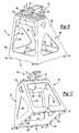
- Figure 11is a side perspective view of a kinematic metrology sensor support assembly suitable for attachment to a floor of the workstation;
- Figure 12is a side view of the kinematic metrology receiver and support assembly shown in Figure 11 with the sensor and support removed;
- Figure 13is a partial side perspective view of Figure 12 with the metrology receiver support removed;
- Figure 14is an exploded side view of an alternative embodiment of a metrology sensor and support assembly also illustrating a laser reflective CMM target or sensor of a laser tracker for independently determining the location and orientation of the metrology sensor;
- Figure 15is a side perspective partially schematic view ot the use of the laser projection system with a mirror to project a laser template on a target surface outside the field of view of the laser;
- Figure 16is a side perspective view of the laser projection system of this invention mounted on a lift.
- Figure 1illustrates schematically one embodiment of a targetless laser projection system 20 and method of this invention for projecting a laser template 22 on a target surface 24 with a laser projector 26.
- the laser projector 26may be any conventional laser projector, such as the LPS1 laser projector available from the assignee of this application.
- the disclosed embodiment of the targetless laser projection system 20 shown in Figure 1includes a plurality of metrology transmitters 28 at fixed locations preferably within the work area, such as the indoor GPS infrared light metrology transmitters available from Arc Second, Inc. of Dulles, Virginia or the laser trackers described above.
- the targetless laser projection system 20further includes a first plurality of metrology receivers or reflectors 30 at fixed locations relative to the target surface 24 and a second plurality of metrology receivers or reflectors 32 at fixed at locations relative to the laser projector 26.
- first plurality of metrology receivers or reflectors 30at fixed locations relative to the target surface 24
- second plurality of metrology receivers or reflectors 32at fixed at locations relative to the laser projector 26.
- metalology receiversincludes both active receivers, such as for example only indoor GPS receivers described in the above referenced U.S.
- the metrology receivers 32will include a sensor associated with the receiver either as a component of the metrology receiver or a reflector reflecting a signal from the metrology projectors 30 to a sensor which may be located on the projectors 30.
- the method of projecting a laser template 22 on a target surface 24 of this inventionincludes first independently determining a position and orientation of the target surface 24 using an external metrology device.
- thisis accomplished by the combination of the metrology transmitters 28 and the metrology receivers 30, wherein a signal, such as an infrared light beam, is transmitted from the plurality of metrology transmitters 28 to the first plurality of metrology receivers 30at fixed locations relative to the target surface 24.
- the data from the metrology receivers 30is then transmitted to a computer 34 which determines the precise position and orientation of the target surface 24 using computer algorithms as is known in this art and described in the above-referenced patents of the assignee and Arc Second, Inc.
- the method of this inventionfurther includes independently determining a position and orientation of the laser projector 26 using the combination of the metrology transmitters 28 and the second plurality of metrology receivers 32 at fixed locations relative to the laser projector or the metrology receivers 32 as described further below with regard to one preferred embodiment of the laser projector and frame assembly.
- the data from the second plurality of metrology receivers 32is also transmitted to the computer 34 and the computer 34 then determines the position and orientation of the laser projector 26 and the precise position of the laser projector 26 relative to the target surface 24 and the first plurality of metrology receivers 30 using known algorithms.
- the laser from the laser projector 26is then oriented relative to the target surface 24 to project a laser template 22 on the target surface 24 at a predetermined or defined location and orientation without the requirement of laser targets on the target surface 24 or metrology receivers within a field of view of the laser projector 26.
- the second plurality of metrology receivers 32are mounted on a frame 36 preferably but not necessarily fixed relative to the laser projector 26 having an opening 38 therethrough through which the laser 40 may be projected to generate the laser template 22.
- the target surface 24preferably includes at least three metrology receivers 30 and at least three metrology receivers 32 are fixed locations relative to the laser projector 26 or fixed relative to laser targets 42.
- the targetless laser projection system 20 shown in Figure 1thus may also be used to correct for laser image drift or movement of the laser projector 26.
- the frame 36includes a plurality of laser targets 42, such as retroreflective or active laser targets opposite the laser projector and within the field of view of the laser projector 26 and the laser projector periodically scans or tracks the position and orientation of the laser targets 42 and the data is then fed to the computer 34 and a control (not shown) for the positioning of the laser of the laser projector then corrects for laser image drift as is known in this art.
- a conventional laser imaging system described aboverequires laser targets on the target surface 24 within a field of view of the laser projector 26.
- the laser targets 42are also located at fixed locations on the frame 36.
- the laser projection systemincludes at least four laser targets 42 as shown in Figure 1 .
- a conventional laser projectoralso includes a sensor (not shown) which, when retroreflective laser targets are used, receives a reflection from the laser targets 42 for determining the position and orientation of the laser projector 26 for correction of laser image drift as known in this art.
- Figures 2 to 5illustrate an actual application of the targetless laser projection system and method of this invention for projecting laser templates on an aircraft 44.
- a laser projection systemmay be utilized to project a laser template on the aircraft for various applications including, for example, mounting of various fixtures or components on the aircraft and the application of appliques, including insignias and other markings following construction of the aircraft.
- the components of the aircraft 44may be assembled and the joints between the components may then be covered with a carbon fiber composite material which must be accurately located on the aircraft.
- the targetless laser system and method of this inventionis not limited by the application, and the application of the laser projection system and method of this invention for projecting a laser template on the aircraft 44 is for illustrative purposes only.
- the target surfaceis an aircraft 44.
- the disclosed embodiment of the targetless laser projection system of this inventionincludes a plurality of laser projector and frame assemblies 46 which project laser templates onto the aircraft 44 through the frame assembly as described below with reference to Figures 6 and 7 .
- Some of the laser projector and frame assemblies 46are mounted on beams 48 which form part of the ceiling structure of the workstation or bay which receives the aircraft 44 for various applications, such as attachment of fixtures or components or application of appliques, such as insignias, identification, etc.
- the laser projector and frame assemblies 46 attached to the upper beamsthus project downwardly onto the aircraft 44.
- the adjustable stands 50may include two or more laser projector and frame assemblies 46.
- some of the laser projector and frame assemblies 46are mounted on hand carts or trolleys 52 having wheels 54, such that the laser projector and frame assemblies 46 mounted on the hand carts 52 may be easily moved from place to place on the floor 56 of the workstation.
- the carts 52may include an adjustable support (not shown) to tilt the frame assembly 46. All of the laser projector and frame assemblies 46 are movable relative to the support and the aircraft 44.
- the laser projector and frame assemblies 46are mounted on universal joints 58 shown in Figures 6 and 7 described below.
- the targetless laser imaging or projection system shown in Figures 3 to 5further includes a plurality of metrology transmitters 60, such as GPS infrared light transmitters, laser trackers or other metrology transmitters, as described above, located at fixed positions and orientations mounted from both the ceiling beams 48 and the workstation floor 56.
- the metrology transmitters 60 mounted on the beams 48are supported in fixed relation by stanchions 62 and struts 64 as best shown in Figure 4 .
- the floor mounted metrology transmitters 60are mounted on rigid floor supports 68, which are preferably kinematic supports, wherein the metrology transmitters 60 may be removed from and replaced on the floor supports 68 without changing the position and orientation of the metrology transmitters as further described below.
- the targetless laser imaging system shown in Figures 2 to 5further includes a first plurality of metrology receivers 70 as defined above fixed relative to the target surface which, in the disclosed embodiment, is an aircraft 44.
- a commercial or military aircrafthas a number of jack and lift points at precisely known locations normally including a socket, as described below with regard to Figures 8 to 10 .
- the first plurality of metrology receivers 70may be rigidly fixed and oriented relative to the precisely known jack and lift points in most commercial and military aircraft.
- the metrology receivers 70may be fixed at predetermined locations and orientations as described above with regard to Figure 1 .
- the number of the first plurality of metrology receivers 70will depend upon the application. As described above, the combination of the metrology transmitters 60 at fixed locations and the first plurality of metrology receivers 70 at fixed known locations permit the computer (not shown in Figures 2 to 5 ) to determine the precise location and orientation of the aircraft 44.
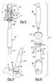
- Figures 6 and 7illustrate one preferred embodiment of the laser projector and frame assembly 46 shown in Figures 2 to 5 .
- the laser projector and frame assembly 46may be supported on a universal support 58 which preferably permits movement or rotation of the frame assembly 46 in at least two axes.
- the disclosed embodiment of the universal joint 58includes a support plate 72 which may be attached to the support for the laser projector and frame assembly 46 and attached to the ceiling beams 48, the adjustable stands 50 or the support structure for the trolleys 52 shown in Figures 3 to 5 and described above.
- the support plates 72 in the disclosed embodimentinclude two end bosses 74 which receive a primary pin or pivot rod 76 and the pivot rod 76 includes a cross rod 78, which is pivotally supported on brackets 80 on the primary support plate 82 of the projector and frame assembly 46.
- the projector and frame assembly 46may be pivoted or rotated about the axes of the pivot rod 76 and the cross rod 78 to adjust the orientation of the laser projector 84 relative to the target surface, such as the aircraft 44 shown in Figures 2 to 5 .
- the laser projector and frame assembly 46may be supported by any suitable support assembly, but the support assembly preferably includes a universal joint or assembly which permits adjustment of the orientation of the laser projector 84.
- the frame 86includes a proximal support surface 88 and a distal open end 90.
- the proximal end of the frame 86is adjacent to the laser projector 84 and the distal end 90 is furthest from the projector 84.
- the distal open end 90which, in the disclosed embodiment, is rectangular, includes an outer surface 92 shown in Figure 7 , having a second plurality of metrology receivers 94 which may project therefrom as shown.
- the laser projector 84is rigidly supported on the proximal support surface 88 and the second plurality of metrology receivers 94 are fixed at predetermined positions and orientations relative to the laser projector 84.
- the metrology transmitters 60 shown in Figures 2 to 5transmit a signal, such as an infrared laser light signal, to the second plurality of metrology receivers 94, located at fixed locations and orientations relative to the laser projector 84 to determine the precise position and orientation of the laser projector 84 in Figures 6 and 7 .
- the frame 86is preferably formed of a material which has a low co-efficient of expansion and contraction, such as a honeycomb carbon fiber.
- the frame 86is also preferably integrally formed, such that the second plurality of metrology receivers 94 are fixed relative to the laser projector 84.
- a suitable material for this applicationis NOMEX® available from E.I. Du Pont de Nemours and Company, which forms a rigid carbon fiber structure having a very low co-efficient of expansion and contraction.
- the integrally formed frameincludes strut portions 96 interconnecting the proximal support surface 88 with the distal open end 90 having triangular and rectangular openings 98 and 100, respectively, to further reduce weight and form a rigid structure.
- the distal open end 90 of the frame 86includes a plurality of laser targets 102, such as conventional retroreflective laser targets commercially available from the assignee of this application.
- the laser targets 102are located within a field of view of the laser projector and fixed relative to the laser projector, such that the laser projector 84 periodically scans the laser targets 102 to correct for laser image drift and to determine the location of the laser projector 84 where the laser projector 84 is not fixed relative to the frame assembly 46 as described.
- the laser beamis reflected back to a sensor in the laser projector 84 (not shown) to control a mirror in the laser projector and correct for laser image drift as is known in this art.
- the laser targetsare fixed at locations on or adjacent the target surface.
- the laser projector 84includes a window 104 opposite the open distal end 92 of the frame 86 and the laser beam is then projected through the open distal end 92 of the frame 86.
- an object of the laser projection and frame assembly 46 of this inventionis to determine the position and orientation of the laser projector 84 relative to the metrology transmitters 60 (shown in Figures 2 to 5 ) and thus the position and orientation of the laser projector 84 relative to the target surface 44. This can be accomplished by fixing the laser projector 84 relative to the metrology receivers 94 on the frame 86, as described above.
- the laser targets 102may be fixed relative to the metrology receivers 94 and the laser projector 84 may then be movable or at an "unknown" location relative to frame assembly 46 and the position and orientation of the laser projector 84 may then be precisely determined by scanning the laser targets 102 with the laser projector 84 because the laser targets 102 are fixed relative to the metrology receivers 94.
- the location of the laser targets 102 on the frame 86 within a field of view of the laser projector 84may be used to determine the location and orientation of the laser projector 84 relative to the target surface.
- Figures 8 to 10illustrate two alternative embodiments for rigidly mounting a "vector bar” metrology receiver system, such as a GPS infrared light receiver as now described.
- the vector bar 106includes two sensors or metrology receivers 108 and 110 which are spaced a predetermined distance on a common axis, such that the GPS metrology system can accurately and precisely determine the position and orientation of the metrology receivers 106.
- Such vector barsare commercially available from Arc Second, Inc. and thus no further description of the vector bar is necessary for a person skilled in this art.
- the metrology receiversmay include a plurality of mirrors, CMM or other reflector which reflect a signal from the metrology transmitters back to a sensor of the metrology transmitters or laser trackers.
- the first plurality of metrology receivers 70 in Figures 2 to 5are fixed at predetermined locations and orientations relative to the aircraft 44, such as the hoist and lift points of the aircraft which are typically located at the bulkheads and are precisely known in any commercial or military aircraft.
- the metrology receiver assembly shown in Figure 8is for mounting the vector bar 106 under the wing of the aircraft and the embodiment of the vector bar mounting assembly shown in Figures 9 and 10 was designed for the forward installations.
- the preferred mountingwill depend upon the application and the mounting available on the aircraft 44 or other target surface.
- the mounting assembly 112 for the vector bar 106 shown in Figure 8includes a bushing or aircraft interface fixture 112 having a tubular end portion 116 received in a cylindrical opening in the aircraft 44 typically under the wing of the aircraft having a spherical seat 118 receiving a bearing 120 having a spherical end portion 122.
- the bearingis rigidly fixed to the bushing 112 by a locking nut 124 having a helical internal surface 126 as shown in Figure 10 and a locking ring 127.
- the assemblyis rigidly retained together by bolts 128 each having a threaded end portion 130, as shown in Figure 10 , which threadably receive balls or spheres 132 having a threaded opening 134.
- the spheres or balls 132are preferably formed of a relatively rigid polymeric material, such as Nylon, whereon one end ball 132 is received in the tubular end portion 116 of the bushing 114 and the opposed ball 132 is received in the helical internal surface 126 of the locking nut 124, such that upon turning of the locking nut 124, the bolts 128 are tensioned, rigidly locking the vector bar metrology receiver assembly in place. Because of the spherical interface between the bushing 114 and the bearing 120, the vector bar 106 may be oriented prior to locking the assembly in place.
- the mounting assembly for the vector bar 106 shown in Figures 9 and 10is similar, but not identical to the mounting assembly 112 shown in Figure 8 . In the mounting assembly 136 shown in Figures 9 and 10 , the bushing 114 and bearing 120 has been replaced by the aircraft interface fixture 138 shown in Figure 10 , but is otherwise identical to the mounting assembly 112 shown in Figure 8 .
- the mounting assemblies 112 and 136rigidly mount the vector bar metrology receiver 106 fixed known locations, providing an accurate location for the metrology receivers in a predetermined orientation such that the metrology device can accurately locate both the location and orientation of the aircraft 44 in Figures 2 to 5 and the aircraft may be moved to any suitable location within the bay or workstation for subsequent operations or maintenance as required.
- the systemfurther includes a third plurality of metrology receivers 140 which, in the disclosed embodiment, are floor mounted.
- the third plurality of metrology receivers 140provide additional data to the computer (not shown) and further accuracy of the metrology system, particularly the location and orientation of the aircraft 44.
- the third plurality of metrology receivers 140are floor mounted, it would be desirable to remove the metrology receivers 140 as the aircraft or other part is received in the workstation and replace the metrology receivers 140 without modifying the position and orientation of the receivers.
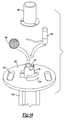
- FIGs 11 to 13illustrate one preferred embodiment of a kinematic mount for the metrology receivers 140 as now described.
- the disclosed embodiment of the kinematic mountincludes a mounting plate 142 which is permanently and rigidly attached to the floor 56 of the workstation, such as by bolts 144 which are set into the floor as shown in Figure 12 .
- the mounting plate 142is secured to the floor by nuts 146 or other suitable means.
- a gasket(not shown) may be received between the mounting plate 142 and the floor 56.
- a bottom kinematic plate 148is secured to the mounting plate 142 by any suitable means, such as screws 150 shown in Figure 13 .
- the metrology receivers 140may then be removed from the low profile support plate 142 and bottom kinematic plate 148 for receipt of the aircraft 44 in the workstation and replaced without changing the position and orientation of the metrology receivers 140.
- the disclosed embodiment of the kinematic mount assemblyfurther includes a top kinematic plate 160 which is releasably retained to the bottom kinematic plate 146 in a predetermined orientation as now described.
- the bottom kinematic plate 146includes three projections which, in the disclosed embodiment, are spring biased balls or spheres 162 and the top kinematic plate 160 includes three hemispherical depressions 164 which receive the spherical balls 162, orienting the top kinematic plate 160 relative to the bottom kinematic plate 146 as shown in Figure 13 .
- the bottom kinematic plate 146further includes a central cylindrical magnet 166, as shown in Figure 13 and the top kinematic plate 160 includes a cylindrical opening 168 which receives the cylindrical magnet 166, releasably retaining the top kinematic plate 160 to the bottom kinematic plate 146.
- the magnet 166may be retained to the bottom kinematic plate 146 by any suitable means, such as screws (not shown) received in the threaded openings 170.
- the mounting assemblyfurther includes a support plate 172 secured to the top kinematic plate 160 by screws or bolts 174 shown in Figure 11 .
- the support plate 172supports a metrology receiver support stanchion 176 which is attached to the support plate 172 by suitable fasteners, such as screws (not shown) received in threaded openings 176 shown in Figure 13 .
- the kinematic support assemblyfurther includes a top plate 180 having finger holes 182 forming handles for lifting the upper assembly, including the top kinematic plate 160 from the bottom assembly, including the bottom kinematic plate 146.
- the sensor or metrology receiveis not shown in Figures 11 and 12 , but is enclosed within a cup-shaped cap 184 retained to the top plate 180 by any suitable fasteners, such as screws 186 shown in Figures 11 and 12 .
- the floor mounted metrology receivers 140may be easily removed from the floor 56 by lifting the top plate 180, thereby lifting the stanchion 176, support plate 172 and the top kinematic plate 160 from the bottom kinematic plate 146 and the mounting plate 142 to receive an aircraft 44 for example, into the workstation shown in Figures 2 to 5 and the assembly may then be replaced by mounting the top kinematic plate 160 on the bottom kinematic plate 146 and accurately oriented by receiving the bails 162 in the bottom kinematic plate 146 in the hemispherical openings 164 in the top kinematic plate 160, accurately realigning the assembly.
- the stanchionis formed of a lightweight rigid material which has a low co-efficient of expansion and contraction, such as extruded aluminum and the ends of the stanchion 176 are preferably machined flat to assure accurate alignment of the metrology receiver.
- the floor mounted metrology transmitters 60 shown in Figures 3 to 5may be similarly mounted on kinematic supports, such that the metrology transmitters 60 may be easily removed and replaced without changing the orientation and location of the floor mounted metrology transmitters.
- Figure 14illustrates a further refinement of the laser imaging system of this invention which provides for independent determination of the precise location and orientation of the metrology receiver or sensor 180.
- the metrology receiver 183may be supported on a kinematic support, including stanchion 176 and top plate 180 for removal and replacement of the metrology receiver 183 without changing the position or orientation of the metrology receiver 183.
- the top plate 180includes a cylindrical cup-shaped enclosure or receptacle 185 having an opening 187 specifically configured to receive and orient either a conventional metrology receiver 183, such as an infrared light GPS receiver, or a laser reflector 189 of an independent CMM device.
- the disclosed embodiment of the laser reflector 189is a spherically mounted reflector (SMR). However, a corner cube reflector (CCR) photogrametric target, retroreflective laser target or other CMM sensor or reflector may also be utilized. Because the opening 187 of the cup-shaped receptacle 185 is specifically adapted to receive and accurately orient either the metrology receiver 183 or the laser reflector or receiver 189, the laser reflector receiver 189 may be inserted into the cup-shaped receptacle 185 to independently determine the top center location of the metrology receiver 183 by using a conventional laser tracker.
- the disclosed embodiment of the metrology receiver 183is an indoor GPS infrared light receiver or sensor available from Arc Second, Inc.
- the precise position and orientation of the metrology receiver 183can thus be independently determined with a laser tracking device using a laser reflector, such as the SMR 189 shown in Figure 14 .
- the cup-shaped receptacle 185 in Figure 14is rigidly and accurately mounted on plate 180 by mounting blocks 191.
- Figure 15illustrates a modification of the laser imaging system 20 shown in Figure 1 to project a laser template (not shown) on a target surface which is not within the field of view of the laser projector 26.
- the laser projector 26projects a laser beam 190 onto a mirror 192 or mirrored surface and the laser beam 190 is then reflected from the mirror 192 as shown by arrows 194 to project a laser template on a target surface (not shown) which may be outside the field of view of the laser projector 26.
- the mirror 192may be utilized in a confined space to increase the size of the laser template.
- the mirroris supported in a frame 196 having three metrology receivers 198 preferably fixed at predetermined locations relative to the laser projector 26 permitting the use of the laser imaging system in a targetless laser imaging system as described above. That is, the laser imaging system shown in Figure 15 would include a plurality of metrology transmitters 28 (shown in Figure 1 ) and the frame 196 may also include a plurality of laser targets 200 to compensate for laser image drift.
- the laser targets 200are preferably electronic targets as disclosed in the above-referenced U.S. Patent No. 5,646,859 , rather than retroreflective laser targets.
- the laser projection system shown in Figure 15may be otherwise identical to the laser projection system shown in Figure 1 , except that the laser template is reflected from the mirror 192 onto a target surface.
- FIG 16illustrates a further use and application of a targetless laser system of this invention, wherein a laser projector and frame assembly 46 is mounted on a platform 202, which is mounted on a telescopic piston and cylinder assembly supported by a roof beam 204, for example.
- a pneumatic or hydraulic cylinder 206is fixed to the roof beam 204 and the vertical cylinder 206 telescopically receives a plurality of telescopic pistons 208 connected to the platform 202, such that the platform 202 may be raised or lowered as shown by arrow 210.
- the laser projector and frame assembly 46is supported on the platform by an L-shaped stanchion or frame 212 to project a laser template 214 on the tail 216 of an aircraft.
- the laser imaging system shown in Figure 16may be utilized to project a laser template on any large surface, particularly a large surface located above the floor of a workstation (not shown).
- the laser projection system shown in Figure 16may be otherwise identical to the laser projection system shown in Figures 2 to 5 , including a plurality of metrology transmitters 60 and a first plurality of metrology receivers 70 fixed at predetermined known locations relative to the tail 216 of the aircraft.
- the platform 202is large enough to receive personnel for application of a decal to the laser template 214.
- the metrology transmittersmay project a laser onto a reflective surface of the metrology receivers which is reflected to a sensor or receiver on or connected to the metrology receivers or a laser tracker metrology system.
- the targetless laser projection system of this inventionmay be utilized to project a laser template on any target surface and the invention is not limited to aircraft applications.
- the targetless laser projection system of this inventionis not limited to the laser projector and frame assembly 46 disclosed and the targetless laser projection system of this invention may utilize other methods for correcting for laser drift, other than laser targets, as disclosed.
- the use of a mirror to project a laser template on a target surface outside the field of view of the lasermay also be utilized with conventional laser imaging systems.
Landscapes
- Physics & Mathematics (AREA)
- Engineering & Computer Science (AREA)
- Electromagnetism (AREA)
- General Physics & Mathematics (AREA)
- Radar, Positioning & Navigation (AREA)
- Remote Sensing (AREA)
- Mechanical Engineering (AREA)
- Length Measuring Devices By Optical Means (AREA)
- Lasers (AREA)
- Mechanical Optical Scanning Systems (AREA)
- Transforming Electric Information Into Light Information (AREA)
- Optical Radar Systems And Details Thereof (AREA)
Description
- This invention relates to a method and apparatus for projecting a laser template on a surface particularly including a method and apparatus for projecting a laser template on a surface without laser targets on the surface, or a "targetless" laser projection system and method which increases the application of laser projection systems, including projection of laser templates on larger surfaces, such as aircraft, or where laser targets on the surface would interfere with further operations or conventional laser projection systems would be impractical or impossible.
- Visible laser projection systems are now widely used in industry to project a laser outline or "template" on a work or target surface for assembling large two or three-dimensional structures or assemblies, such as prefabricated roof trusses or aerospace composite components. By precisely characterizing the laser projector and establishing the exact relative position of the laser projector to the assembled structure or composite, the laser projection system is capable of accurately producing a laser image or template at known coordinates on a work or target surface which may be planar or curvilinear.
- For example,
U.S. Patent No. 5,646,859 assigned in part to the assignee of this application, discloses a method and apparatus for defining a laser template for assembling a structure, such as a prefabricated roof truss. The method and apparatus disclosed in this patent includes a laser projector or a plurality of laser projectors mounted above the work surface, a plurality of laser sensors or laser targets fixed at predetermined locations on or adjacent the work surface, a computer and a sensor on the laser projector periodically or continuously scans the laser targets and the reflected light from the laser targets to the sensor of the laser projector determines the precise projection angle associated with the center of each target datum. Using a series of mathematical algorithms, the precise position and orientation of the laser projector relative to the work surface or part is then calculated by the computer. This spatial information, in conjunction with a known display list, allows the laser projector to generate accurate laser templates or laser outlines of the part on the target surface. The laser projector may be fixed relative to the part or work surface or for larger assemblies, a plurality of laser projectors may be used or the laser projectors may be moved relative to the work surface as disclosed in the above-referenced patent. The laser targets or position sensors may include a photo transistor, but in most applications, retroreflective laser targets are now used. - Alignment and calibration methods similar to the above provide the accuracy needed for a wide range of laser projection applications. A typical accuracy specification is ± 0.4mm (0.015 inches) at a 3.048m to 4.572m (10 to 15 foot) stand off distance when measured perpendicular to the laser beam. This approach allows good flexibility in positioning of the laser projectors because the mounting location can be arbitrarily selected so long as a sufficient number of known laser target locations are detectable within the field of view of the laser projector which, as set forth above, must be located at predetermined locations on or adjacent the target surface. In a typical application, a minimum of four laser targets must be located by the sensor system (laser target and sensor) to establish the position of the laser projector relative to the assembled structure or part and the work or target surface.
- However, as set forth above, the requirement for laser targets at fixed locations on or adjacent the target surface has limited the applications for laser projection systems. For example, to guide the placement of carbon fiber composite materials for aerospace structures, it is generally necessary to locate the targets on the target surface which will eventually be covered by the composite material. Further, if the structure or target surface is very large, the required laser projection area may be too large to allow placement of laser or reference targets within the field of view of the laser projectors, making accurate projection difficult. Another problem addressed by the laser projection systems of this invention is laser projection or image drift, which may result from variations in temperature and humidity. Further, the use of reference laser targets is cumbersome, initially requiring mounting of appropriate laser target locations on the target or tool together with accurate measurement of each target coordinate, typically using a theodelite laser tracker or other coordinate measuring machine (CMM). As used herein, CMM covers any coordinate measuring system. Further, when a laser projector is positioned or moved, the laser projector must be trained usually by manual operator guidance, to locate and identify the appropriate laser or reference targets and the placement of the laser projector must also be carefully controlled to ensure that the located laser targets provide an adequate position reference.
- A disclosed embodiment of the laser projector system of this invention utilizes an indoor global positioning system (GPS), such as disclosed in
U.S. Patent Nos. 6,501,543 and6,535,282 of Arc Second, Inc.. Indoor GPS systems are also commercially available from Arc Second, Inc. However, the laser projection systems of this invention are not limited to indoor GPS systems and other external metrology devices may be utilized, including laser theodelite transmitter tracking devices, optical photogrametry devices, camera base systems, infrared transmitter metrology devices and other metrology tracker projection devices. For example, Leica Geosystems and Northern Digital offer laser trackers systems for three-dimensional measurements, wherein the laser from the metrology transmitters is reflected by mirrors or a corner cube reflector (CCR) on a parallel path to a sensor on the metrology transmitters and the data from the receiver is transmitted to a computer to determine the location of the reflector. Such external metrology devices generally include a metrology transmitter, typically a light metrology transmitter, and a plurality of metrology receivers or reflectors which are fixed at predetermined locations. - According to the present invention there is provided a laser projector and frame assembly comprising:
- a frame including a proximal support surface,
- a distal open end opposite said proximal support surface and a strut portion interconnecting said proximal support surface and said distal open end;
- a laser projector mounted on said proximal support surface to project a laser template through said distal open end; and
- a plurality of metrology receivers each having a sensor mounted on said distal open end of the frame assembly receiving a signal from a metrology transmitter for determining the position and orientation of the frame.
- Other aspects of the invention are set out in the subsidiary claims of the application.
- As set forth above, the external metrology device generally includes a plurality of metrology transmitters at fixed locations, typically light metrology transmitters, such as infrared laser light metrology transmitters, and a plurality of metrology receivers also at fixed locations. As used herein, the term "metrology receivers" includes both active receivers, such as the indoor GPS receivers, and passive devices, such as mirrors or corner cube reflectors, which reflect light back to sensors on the metrology transmitters and thus both embodiments have a sensor associated with the receiver. In determining the position and orientation of the target surface using an external metrology device, a first plurality of metrology receivers are fixed relative to the target surface. In determining the position and orientation of a laser projector or projectors using the external metrology device, a second plurality of metrology receivers are fixed relative to the laser projector or projectors. As used herein, the term "fixed" means that the location is stable as required for determination of the location of the transmitters, receivers, laser targets, etc.
- The invention may be used to generate a signal from the external metrology device to a computer and the computer then uses the data received from the metrology device to determine the position and orientation of the laser projector relative to the target surface. The metrology receivers may be connected to the computer or the data from the metrology receivers may be transmitted to the computer by a wireless system. The method then includes orienting a laser from the laser projector or projectors relative to the target surface to a project laser template on the target surface at a predetermined or defined location and orientation using the data from the computer and finally projecting the laser template on the target surface at the predetermined location and orientation with the laser projector. The method of thus eliminates the requirement for laser targets on or adjacent the target surface and calibration of the laser projector relative to laser targets on or adjacent the target surface and is thus "targetless". Further, the metrology receivers do not have to be within a field of view of the laser projector or projectors.
- A preferred embodiment may also be utilized to correct for laser projection or image drift or movement of the laser projector without the requirement for laser targets fixed at predetermined locations on or adjacent the target surface and calibration of the laser projector relative to such laser targets as described above. A disclosed embodiment includes periodically or continuously projecting a laser from the laser projector on laser targets within a field of view of the laser projector. That is, rather than scanning laser targets fixed at predetermined locations relative to the target surface, the method of correcting for laser drift includes fixing laser targets relative to the projector, rather than the target surface. Alternatively, the laser targets may be fixed relative to the metrology receivers within a field of view of the laser projector, permitting location of the laser projector by scanning the laser targets. As described below, the laser projector is supported in a frame assembly having laser targets on the frame assembly opposite the laser projector and the laser projector then periodically or continuously scans the laser target to correct for laser drift or movement of the laser projector. Where the laser targets are retroreflective targets, as described above, the method includes reflecting the laser beam from the laser targets to a sensor on the laser projector and generating a signal to a computer connected to a control which corrects for laser image drift or movement of the laser projector.
- The method of using the invention includes periodically scanning the laser targets on the distal open end of the frame assembly and correcting for laser image drift or movement of the laser projector. However, where the metrology receivers are fixed relative to the laser targets, the laser projector may move relative to the frame and determine its position and orientation by scanning the laser targets. As used herein, the term "periodically" includes continuously scanning the laser targets and the laser targets may be retroreflective targets or any suitable laser target or position sensor, as disclosed for example in the above referenced
U.S. Patent No. 5,646,859 . - The "targetless" laser imaging system of this invention may include a plurality of metrology transmitters located at fixed locations, a laser projector or a plurality of laser projectors, a first plurality of metrology receivers or target reflectors and receivers on the metrology transmitters, as described above, at fixed locations relative to the target surface and second plurality of metrology receivers or target reflectors located at fixed locations relative to the laser projector. The laser imaging system may include a computer receiving data from the metrology receivers or sensors determining the precise location and orientation of the laser projector relative to the target surface and controlling the laser projector to project a laser template on the target surface at the predetermined or defined location and orientation. As described above, the laser imaging system may further include a plurality of laser targets at fixed locations relative to the laser projector within a field of view of the laser projector or the laser projector may be movable provided the laser targets are fixed relative to the metrology receivers and the computer then controls the laser projector to periodically scan the laser targets and compensate for laser image drift or movement of the laser projector.
- Where the frame assembly also includes laser targets opposite the laser projector, as described above, the laser targets must be spaced from the laser projector and the disclosed embodiment of the frame assembly includes strut portions interconnecting the support surface and the open distal end of the frame assembly. In one preferred embodiment of the laser projector and sensor assembly, the frame assembly is integrally formed from a material having a low co-efficient of expansion and contraction to avoid errors due to thermal expansion or contraction, such as a carbon fiber composite. Because the location and orientation of the metrology receivers or reflectors is fixed relative to the metrology receivers or the laser projector, the laser projector or projectors may be moved relative to the target surface as required by the application. In the disclosed embodiments, the laser projector and frame assembly is supported on a universal joint, permitting movement of the laser projector in at least two axes. As disclosed herein, the laser projectors may also be supported on carts or dollies for ease of placement of the laser projectors relative to the target surface. Further, because the first plurality of metrology receivers or reflectors are fixed at predetermined known locations relative to the target surface, the target surface may also be moved to relative to the laser projectors.
- As set forth above, the laser projection system is particularly, but not exclusively suitable for projecting a laser template on a target surface, where laser targets would interfere with subsequent operations, such as ply layup on large target surfaces, such as an aircraft body, for subsequent operations, such as the application of decals, placement of fixtures and covering the joints between the components of the target surface, such as an aircraft. Of course, however, the laser projection system is not limited to any particular application. In such applications, however, it is desirable to fix the metrology receivers or reflectors on stanchions, such that the reflector or receiver is located above the floor for ease of reference in determining the position and orientation of the target surface. In one preferred embodiment of the metrology receiver assembly of this system, the receiver assembly may be removed from the support and replaced without changing the position and orientation of the metrology receiver. In this embodiment, the metrology receiver assembly includes a support stanchion adapted to be permanently affixed to a support in a workstation in a predetermined location. A bottom kinematic plate is fixed to the top of the support stanchion and the assembly includes a receiver support member having a top kinematic plate secured to the support member releasably attached to the bottom kinematic plate. In a preferred embodiment of the receiver assembly, one of the top and bottom kinematic plates includes a plurality of spaced projecting portions and the other of the top and bottom kinematic plates has a plurality of spaced recesses configured to receive the spaced projecting portions to align and orient the top kinematic plate relative to the bottom kinematic plate, such that the top kinematic plate, receiver support and metrology receiver or reflector may be removed from and replaced on the support stanchion without changing the position and orientation of the metrology receiver. In the disclosed embodiment of the metrology receiver assembly of this system, the top kinematic plate is releasably attached to the bottom kinematic plate by a magnet, such that the top kinematic plate, receiver support and metrology receiver may be easily removed from and replaced on the support stanchion without changing the position and orientation of the assembly.
- It may also be desirable to independently determine the position and orientation of the metrology receivers or reflectors in many applications. The laser projection system includes metrology receivers having a support adapted to be fixed at a predetermined location and orientation, as described above. In one disclosed embodiment of the metrology receiver assembly, the support includes a cup-shaped enclosure mounted on the support, a first metrology receiver adapted to receive or reflect a signal from a metrology transmitter, as described above, and a second receiver to reflect a laser, such as a spherical mounted reflector (SMR) or a corner cube reflector (CCR) or a photogrametric or retroreflective laser target, wherein the cup-shaped enclosure is configured to receive and orient one of the first metrology receivers or the CMM laser reflector receiver, such that the position and orientation of the metrology receiver may be independently determined and confirmed for accuracy as required by certain applications.
- It is also possible using the laser projection system to project a laser template on a target surface which is located outside the field of view of the laser projector. In one disclosed embodiment of the laser projection system of this invention, the laser template is projected on a mirrored surface to project the laser template on a target surface located outside the field of view of the laser projector. The mirror may be supported by a frame assembly having laser targets as described above. Where the laser projector and mirror assembly is utilized in a targetless laser projection system, the mirror frame may also include metrology receivers or reflectors, as described above. Finally, the laser projector of the laser projector system of this invention may be mounted on other conveyances, such as a lift depending upon the application. In one disclosed embodiment, the laser projector and frame assembly is mounted on a platform which may also be used by personnel for subsequent operations and the platform is mounted on a piston telescopically received in a vertical hydraulic or pneumatic cylinder attached to the roof or ceiling of a workstation, permitting the platform to be moved vertically for applications requiring vertical movement.
- As will be understood by those skilled in this art, various modifications may be made to the laser projection systems of this invention within the purview of the appended claims. For example, the laser projection system of this invention may be utilized with any metrology device, including but not limited to indoor GPS metrology and laser tracking devices as described above. The computer used in the method of this invention and the laser projection or imaging systems may also be a plurality of computers. The examples of the method and apparatus disclosed in the following description of the preferred embodiments of this invention and the appended drawings are for illustrative purposes only and do not limit the inventions disclosed herein except as specifically set forth in the following claims.
Figure 1 is a partially schematic side elevation of the basic components of a targetless laser projection system of this invention and method of projecting a laser template on a target surface;Figure 2 is a top view of an embodiment of a workstation for projecting a laser template on an aircraft for subsequent operations;Figure 3 is a side view ofFigure 1 ;Figure 4 is an end view ofFigures 2 and3 ;Figure 5 is a front partial view ofFigures 2 to 4 with upper portions of the roof assembly removed for a clearer understanding ofFigures 2 to 4 ;Figure 6 is a side perspective view of one embodiment of a laser projector and frame assembly of this invention shown inFigures 2 to 5 ;Figure 7 is a side perspective view of the laser projector and frame assembly shown inFigure 6 with the frame tilted on the universal support;Figure 8 is a side partially cross-sectioned side view of one embodiment of a vector bar metrology sensor or receiver and removable rigid connector and support assembly suitable for attachment of the metrology receiver to an aircraft;Figure 9 is an exploded view of an alternative embodiment of a vector bar metrology receiver and removable rigid connector and support assembly;Figure 10 is a side perspective view of the assembly shown inFigure 9 following assembly to the target surface, such as an aircraft;Figure 11 is a side perspective view of a kinematic metrology sensor support assembly suitable for attachment to a floor of the workstation;Figure 12 is a side view of the kinematic metrology receiver and support assembly shown inFigure 11 with the sensor and support removed;Figure 13 is a partial side perspective view ofFigure 12 with the metrology receiver support removed;Figure 14 is an exploded side view of an alternative embodiment of a metrology sensor and support assembly also illustrating a laser reflective CMM target or sensor of a laser tracker for independently determining the location and orientation of the metrology sensor;Figure 15 is a side perspective partially schematic view ot the use of the laser projection system with a mirror to project a laser template on a target surface outside the field of view of the laser; andFigure 16 is a side perspective view of the laser projection system of this invention mounted on a lift.Figure 1 illustrates schematically one embodiment of a targetlesslaser projection system 20 and method of this invention for projecting alaser template 22 on atarget surface 24 with alaser projector 26. Thelaser projector 26 may be any conventional laser projector, such as the LPS1 laser projector available from the assignee of this application. The disclosed embodiment of the targetlesslaser projection system 20 shown inFigure 1 includes a plurality ofmetrology transmitters 28 at fixed locations preferably within the work area, such as the indoor GPS infrared light metrology transmitters available from Arc Second, Inc. of Dulles, Virginia or the laser trackers described above. Alternatively, other transmitter metrology devices may be utilized, as described above, including but not limited to, laser theodelite transmitter tracking devices, optical photogrametery devices, camera based systems, other infrared transmitter metrology devices and other tracker projection devices. The targetlesslaser projection system 20 further includes a first plurality of metrology receivers orreflectors 30 at fixed locations relative to thetarget surface 24 and a second plurality of metrology receivers orreflectors 32 at fixed at locations relative to thelaser projector 26. Hereinafter, for ease of description, it will be understood that the term "metrology receivers" includes both active receivers, such as for example only indoor GPS receivers described in the above referenced U.S. Patents of Arc Second Inc., and passive devices, such as mirrors or reflectors, in combination with sensors or receivers which may for example, be on the metrology transmitters or laser trackers. Thus, in either embodiment, themetrology receivers 32 will include a sensor associated with the receiver either as a component of the metrology receiver or a reflector reflecting a signal from themetrology projectors 30 to a sensor which may be located on theprojectors 30.- As described above, the method of projecting a
laser template 22 on atarget surface 24 of this invention includes first independently determining a position and orientation of thetarget surface 24 using an external metrology device. In the embodiment of the targetlesslaser projection system 20 shown inFigure 1 , this is accomplished by the combination of themetrology transmitters 28 and themetrology receivers 30, wherein a signal, such as an infrared light beam, is transmitted from the plurality ofmetrology transmitters 28 to the first plurality of metrology receivers 30at fixed locations relative to thetarget surface 24. The data from themetrology receivers 30 is then transmitted to acomputer 34 which determines the precise position and orientation of thetarget surface 24 using computer algorithms as is known in this art and described in the above-referenced patents of the assignee and Arc Second, Inc. The method of this invention further includes independently determining a position and orientation of thelaser projector 26 using the combination of themetrology transmitters 28 and the second plurality ofmetrology receivers 32 at fixed locations relative to the laser projector or themetrology receivers 32 as described further below with regard to one preferred embodiment of the laser projector and frame assembly. The data from the second plurality ofmetrology receivers 32 is also transmitted to thecomputer 34 and thecomputer 34 then determines the position and orientation of thelaser projector 26 and the precise position of thelaser projector 26 relative to thetarget surface 24 and the first plurality ofmetrology receivers 30 using known algorithms. The laser from thelaser projector 26 is then oriented relative to thetarget surface 24 to project alaser template 22 on thetarget surface 24 at a predetermined or defined location and orientation without the requirement of laser targets on thetarget surface 24 or metrology receivers within a field of view of thelaser projector 26. - In the embodiment of the targetless
laser projection system 20 shown inFigure 1 , the second plurality ofmetrology receivers 32 are mounted on aframe 36 preferably but not necessarily fixed relative to thelaser projector 26 having anopening 38 therethrough through which thelaser 40 may be projected to generate thelaser template 22. As shown, thetarget surface 24 preferably includes at least threemetrology receivers 30 and at least threemetrology receivers 32 are fixed locations relative to thelaser projector 26 or fixed relative to laser targets 42. The targetlesslaser projection system 20 shown inFigure 1 thus may also be used to correct for laser image drift or movement of thelaser projector 26. In the disclosed embodiment, theframe 36 includes a plurality oflaser targets 42, such as retroreflective or active laser targets opposite the laser projector and within the field of view of thelaser projector 26 and the laser projector periodically scans or tracks the position and orientation of the laser targets 42 and the data is then fed to thecomputer 34 and a control (not shown) for the positioning of the laser of the laser projector then corrects for laser image drift as is known in this art. However, as set forth above, a conventional laser imaging system described above requires laser targets on thetarget surface 24 within a field of view of thelaser projector 26. The laser targets 42 are also located at fixed locations on theframe 36. In a preferred embodiment, the laser projection system includes at least fourlaser targets 42 as shown inFigure 1 . As set forth above, a conventional laser projector also includes a sensor (not shown) which, when retroreflective laser targets are used, receives a reflection from the laser targets 42 for determining the position and orientation of thelaser projector 26 for correction of laser image drift as known in this art. Figures 2 to 5 illustrate an actual application of the targetless laser projection system and method of this invention for projecting laser templates on anaircraft 44. As will be understood by those familiar with aircraft design and construction, a laser projection system may be utilized to project a laser template on the aircraft for various applications including, for example, mounting of various fixtures or components on the aircraft and the application of appliques, including insignias and other markings following construction of the aircraft. In a typical application, for example, the components of theaircraft 44 may be assembled and the joints between the components may then be covered with a carbon fiber composite material which must be accurately located on the aircraft. However, as set forth above, the targetless laser system and method of this invention is not limited by the application, and the application of the laser projection system and method of this invention for projecting a laser template on theaircraft 44 is for illustrative purposes only. However, in the embodiment of the targetless laser projection system shown inFigures 2 to 5 , the target surface is anaircraft 44.- As shown in
Figures 2 to 5 , the disclosed embodiment of the targetless laser projection system of this invention includes a plurality of laser projector andframe assemblies 46 which project laser templates onto theaircraft 44 through the frame assembly as described below with reference toFigures 6 and 7 . Some of the laser projector andframe assemblies 46 are mounted onbeams 48 which form part of the ceiling structure of the workstation or bay which receives theaircraft 44 for various applications, such as attachment of fixtures or components or application of appliques, such as insignias, identification, etc. The laser projector andframe assemblies 46 attached to the upper beams thus project downwardly onto theaircraft 44. Some of the laser projector and frame assemblies are mounted on adjustable stands orstanchions 50 as shown inFigures 3 and4 , wherein the adjustable stands 50 may include two or more laser projector andframe assemblies 46. Further, some of the laser projector andframe assemblies 46 are mounted on hand carts ortrolleys 52 havingwheels 54, such that the laser projector andframe assemblies 46 mounted on thehand carts 52 may be easily moved from place to place on thefloor 56 of the workstation. Thecarts 52 may include an adjustable support (not shown) to tilt theframe assembly 46. All of the laser projector andframe assemblies 46 are movable relative to the support and theaircraft 44. In one preferred embodiment, the laser projector andframe assemblies 46 are mounted onuniversal joints 58 shown inFigures 6 and 7 described below. - The targetless laser imaging or projection system shown in
Figures 3 to 5 further includes a plurality ofmetrology transmitters 60, such as GPS infrared light transmitters, laser trackers or other metrology transmitters, as described above, located at fixed positions and orientations mounted from both the ceiling beams 48 and theworkstation floor 56. Themetrology transmitters 60 mounted on thebeams 48 are supported in fixed relation bystanchions 62 and struts 64 as best shown inFigure 4 . The floor mountedmetrology transmitters 60 are mounted on rigid floor supports 68, which are preferably kinematic supports, wherein themetrology transmitters 60 may be removed from and replaced on the floor supports 68 without changing the position and orientation of the metrology transmitters as further described below. - The targetless laser imaging system shown in
Figures 2 to 5 further includes a first plurality ofmetrology receivers 70 as defined above fixed relative to the target surface which, in the disclosed embodiment, is anaircraft 44. As will be understood by those skilled in this art, a commercial or military aircraft has a number of jack and lift points at precisely known locations normally including a socket, as described below with regard toFigures 8 to 10 . The first plurality ofmetrology receivers 70 may be rigidly fixed and oriented relative to the precisely known jack and lift points in most commercial and military aircraft. Alternatively, where the target surface is other than an aircraft, themetrology receivers 70 may be fixed at predetermined locations and orientations as described above with regard toFigure 1 . The number of the first plurality ofmetrology receivers 70 will depend upon the application. As described above, the combination of themetrology transmitters 60 at fixed locations and the first plurality ofmetrology receivers 70 at fixed known locations permit the computer (not shown inFigures 2 to 5 ) to determine the precise location and orientation of theaircraft 44. Figures 6 and 7 illustrate one preferred embodiment of the laser projector andframe assembly 46 shown inFigures 2 to 5 . As stated above, the laser projector andframe assembly 46 may be supported on auniversal support 58 which preferably permits movement or rotation of theframe assembly 46 in at least two axes. The disclosed embodiment of theuniversal joint 58 includes asupport plate 72 which may be attached to the support for the laser projector andframe assembly 46 and attached to the ceiling beams 48, the adjustable stands 50 or the support structure for thetrolleys 52 shown inFigures 3 to 5 and described above. Thesupport plates 72 in the disclosed embodiment include twoend bosses 74 which receive a primary pin orpivot rod 76 and thepivot rod 76 includes across rod 78, which is pivotally supported onbrackets 80 on theprimary support plate 82 of the projector andframe assembly 46. Thus, the projector andframe assembly 46 may be pivoted or rotated about the axes of thepivot rod 76 and thecross rod 78 to adjust the orientation of thelaser projector 84 relative to the target surface, such as theaircraft 44 shown inFigures 2 to 5 . As will be understood, however, the laser projector andframe assembly 46 may be supported by any suitable support assembly, but the support assembly preferably includes a universal joint or assembly which permits adjustment of the orientation of thelaser projector 84.- In a preferred embodiment of the
frame 86 of the laser projector andframe assembly 46, theframe 86 includes aproximal support surface 88 and a distalopen end 90. As used herein, for reference purposes only, the proximal end of theframe 86 is adjacent to thelaser projector 84 and thedistal end 90 is furthest from theprojector 84. The distalopen end 90 which, in the disclosed embodiment, is rectangular, includes anouter surface 92 shown inFigure 7 , having a second plurality ofmetrology receivers 94 which may project therefrom as shown. In a preferred embodiment of the laser projector andframe assembly 46, thelaser projector 84 is rigidly supported on theproximal support surface 88 and the second plurality ofmetrology receivers 94 are fixed at predetermined positions and orientations relative to thelaser projector 84. Thus, as described above with regard toFigure 1 , themetrology transmitters 60 shown inFigures 2 to 5 , transmit a signal, such as an infrared laser light signal, to the second plurality ofmetrology receivers 94, located at fixed locations and orientations relative to thelaser projector 84 to determine the precise position and orientation of thelaser projector 84 inFigures 6 and 7 . Theframe 86 is preferably formed of a material which has a low co-efficient of expansion and contraction, such as a honeycomb carbon fiber. Theframe 86 is also preferably integrally formed, such that the second plurality ofmetrology receivers 94 are fixed relative to thelaser projector 84. A suitable material for this application is NOMEX® available from E.I. Du Pont de Nemours and Company, which forms a rigid carbon fiber structure having a very low co-efficient of expansion and contraction. In the disclosed embodiment of the frame, the integrally formed frame includesstrut portions 96 interconnecting theproximal support surface 88 with the distalopen end 90 having triangular andrectangular openings - In a preferred embodiment of the laser projector and
frame assembly 46 of this invention, the distalopen end 90 of theframe 86 includes a plurality oflaser targets 102, such as conventional retroreflective laser targets commercially available from the assignee of this application. As best shown inFigure 6 , the laser targets 102 are located within a field of view of the laser projector and fixed relative to the laser projector, such that thelaser projector 84 periodically scans the laser targets 102 to correct for laser image drift and to determine the location of thelaser projector 84 where thelaser projector 84 is not fixed relative to theframe assembly 46 as described. Where the laser targets 102 are retroreflective targets, the laser beam is reflected back to a sensor in the laser projector 84 (not shown) to control a mirror in the laser projector and correct for laser image drift as is known in this art. However, as discussed above, in a conventional laser imaging system, the laser targets are fixed at locations on or adjacent the target surface. Thelaser projector 84 includes awindow 104 opposite the opendistal end 92 of theframe 86 and the laser beam is then projected through the opendistal end 92 of theframe 86. As will be understood from the above description, an object of the laser projection andframe assembly 46 of this invention is to determine the position and orientation of thelaser projector 84 relative to the metrology transmitters 60 (shown inFigures 2 to 5 ) and thus the position and orientation of thelaser projector 84 relative to thetarget surface 44. This can be accomplished by fixing thelaser projector 84 relative to themetrology receivers 94 on theframe 86, as described above. Alternatively, where theframe 86 also includeslaser targets 102, the laser targets 102 may be fixed relative to themetrology receivers 94 and thelaser projector 84 may then be movable or at an "unknown" location relative to frameassembly 46 and the position and orientation of thelaser projector 84 may then be precisely determined by scanning the laser targets 102 with thelaser projector 84 because the laser targets 102 are fixed relative to themetrology receivers 94. Thus, the location of the laser targets 102 on theframe 86 within a field of view of thelaser projector 84 may be used to determine the location and orientation of thelaser projector 84 relative to the target surface. Figures 8 to 10 illustrate two alternative embodiments for rigidly mounting a "vector bar" metrology receiver system, such as a GPS infrared light receiver as now described. As is known in this art, thevector bar 106 includes two sensors ormetrology receivers metrology receivers 106. Such vector bars are commercially available from Arc Second, Inc. and thus no further description of the vector bar is necessary for a person skilled in this art. Alternatively, the metrology receivers may include a plurality of mirrors, CMM or other reflector which reflect a signal from the metrology transmitters back to a sensor of the metrology transmitters or laser trackers. As set forth above, the first plurality ofmetrology receivers 70 inFigures 2 to 5 are fixed at predetermined locations and orientations relative to theaircraft 44, such as the hoist and lift points of the aircraft which are typically located at the bulkheads and are precisely known in any commercial or military aircraft. Although not relevant to the targetless laser projection system of this invention, the metrology receiver assembly shown inFigure 8 is for mounting thevector bar 106 under the wing of the aircraft and the embodiment of the vector bar mounting assembly shown inFigures 9 and 10 was designed for the forward installations. As set forth above, the preferred mounting will depend upon the application and the mounting available on theaircraft 44 or other target surface.- The mounting
assembly 112 for thevector bar 106 shown inFigure 8 includes a bushing oraircraft interface fixture 112 having atubular end portion 116 received in a cylindrical opening in theaircraft 44 typically under the wing of the aircraft having aspherical seat 118 receiving abearing 120 having aspherical end portion 122. The bearing is rigidly fixed to thebushing 112 by a lockingnut 124 having a helicalinternal surface 126 as shown inFigure 10 and alocking ring 127. The assembly is rigidly retained together bybolts 128 each having a threadedend portion 130, as shown inFigure 10 , which threadably receive balls orspheres 132 having a threadedopening 134. The spheres orballs 132 are preferably formed of a relatively rigid polymeric material, such as Nylon, whereon oneend ball 132 is received in thetubular end portion 116 of thebushing 114 and theopposed ball 132 is received in the helicalinternal surface 126 of the lockingnut 124, such that upon turning of the lockingnut 124, thebolts 128 are tensioned, rigidly locking the vector bar metrology receiver assembly in place. Because of the spherical interface between thebushing 114 and thebearing 120, thevector bar 106 may be oriented prior to locking the assembly in place. The mounting assembly for thevector bar 106 shown inFigures 9 and 10 is similar, but not identical to the mountingassembly 112 shown inFigure 8 . In the mountingassembly 136 shown inFigures 9 and 10 , thebushing 114 and bearing 120 has been replaced by theaircraft interface fixture 138 shown inFigure 10 , but is otherwise identical to the mountingassembly 112 shown inFigure 8 . - As will be understood from the above description, the mounting
assemblies bar metrology receiver 106 fixed known locations, providing an accurate location for the metrology receivers in a predetermined orientation such that the metrology device can accurately locate both the location and orientation of theaircraft 44 inFigures 2 to 5 and the aircraft may be moved to any suitable location within the bay or workstation for subsequent operations or maintenance as required. In one preferred embodiment of the targetless laser imaging or projection system shown inFigures 2 to 5 , the system further includes a third plurality ofmetrology receivers 140 which, in the disclosed embodiment, are floor mounted. The third plurality ofmetrology receivers 140 provide additional data to the computer (not shown) and further accuracy of the metrology system, particularly the location and orientation of theaircraft 44. However, because the third plurality ofmetrology receivers 140 are floor mounted, it would be desirable to remove themetrology receivers 140 as the aircraft or other part is received in the workstation and replace themetrology receivers 140 without modifying the position and orientation of the receivers. Figures 11 to 13 illustrate one preferred embodiment of a kinematic mount for themetrology receivers 140 as now described. The disclosed embodiment of the kinematic mount includes a mountingplate 142 which is permanently and rigidly attached to thefloor 56 of the workstation, such as bybolts 144 which are set into the floor as shown inFigure 12 . The mountingplate 142 is secured to the floor bynuts 146 or other suitable means. A gasket (not shown) may be received between the mountingplate 142 and thefloor 56. A bottom kinematic plate 148 is secured to the mountingplate 142 by any suitable means, such asscrews 150 shown inFigure 13 . As will be understood from the following description, themetrology receivers 140 may then be removed from the lowprofile support plate 142 and bottom kinematic plate 148 for receipt of theaircraft 44 in the workstation and replaced without changing the position and orientation of themetrology receivers 140. The disclosed embodiment of the kinematic mount assembly further includes a topkinematic plate 160 which is releasably retained to the bottomkinematic plate 146 in a predetermined orientation as now described. In the disclosed embodiment, the bottomkinematic plate 146 includes three projections which, in the disclosed embodiment, are spring biased balls orspheres 162 and the topkinematic plate 160 includes threehemispherical depressions 164 which receive thespherical balls 162, orienting the topkinematic plate 160 relative to the bottomkinematic plate 146 as shown inFigure 13 .- In the disclosed embodiment of the kinematic mount, the bottom
kinematic plate 146 further includes a centralcylindrical magnet 166, as shown inFigure 13 and the topkinematic plate 160 includes acylindrical opening 168 which receives thecylindrical magnet 166, releasably retaining the topkinematic plate 160 to the bottomkinematic plate 146. Themagnet 166 may be retained to the bottomkinematic plate 146 by any suitable means, such as screws (not shown) received in the threadedopenings 170. The mounting assembly further includes asupport plate 172 secured to the topkinematic plate 160 by screws orbolts 174 shown inFigure 11 . Thesupport plate 172 supports a metrologyreceiver support stanchion 176 which is attached to thesupport plate 172 by suitable fasteners, such as screws (not shown) received in threadedopenings 176 shown inFigure 13 . The kinematic support assembly further includes atop plate 180 havingfinger holes 182 forming handles for lifting the upper assembly, including the topkinematic plate 160 from the bottom assembly, including the bottomkinematic plate 146. The sensor or metrology receive is not shown inFigures 11 and 12 , but is enclosed within a cup-shapedcap 184 retained to thetop plate 180 by any suitable fasteners, such asscrews 186 shown inFigures 11 and 12 . - As will now be understood from the above description, the floor mounted
metrology receivers 140 may be easily removed from thefloor 56 by lifting thetop plate 180, thereby lifting thestanchion 176,support plate 172 and the topkinematic plate 160 from the bottomkinematic plate 146 and the mountingplate 142 to receive anaircraft 44 for example, into the workstation shown inFigures 2 to 5 and the assembly may then be replaced by mounting the topkinematic plate 160 on the bottomkinematic plate 146 and accurately oriented by receiving thebails 162 in the bottomkinematic plate 146 in thehemispherical openings 164 in the topkinematic plate 160, accurately realigning the assembly. In one preferred embodiment, the stanchion is formed of a lightweight rigid material which has a low co-efficient of expansion and contraction, such as extruded aluminum and the ends of thestanchion 176 are preferably machined flat to assure accurate alignment of the metrology receiver. The floor mountedmetrology transmitters 60 shown inFigures 3 to 5 may be similarly mounted on kinematic supports, such that themetrology transmitters 60 may be easily removed and replaced without changing the orientation and location of the floor mounted metrology transmitters. Figure 14 illustrates a further refinement of the laser imaging system of this invention which provides for independent determination of the precise location and orientation of the metrology receiver orsensor 180. As discussed above with regard toFigures 11 to 13 , themetrology receiver 183 may be supported on a kinematic support, includingstanchion 176 andtop plate 180 for removal and replacement of themetrology receiver 183 without changing the position or orientation of themetrology receiver 183. However, in this embodiment, thetop plate 180 includes a cylindrical cup-shaped enclosure orreceptacle 185 having anopening 187 specifically configured to receive and orient either aconventional metrology receiver 183, such as an infrared light GPS receiver, or alaser reflector 189 of an independent CMM device. The disclosed embodiment of thelaser reflector 189 is a spherically mounted reflector (SMR). However, a corner cube reflector (CCR) photogrametric target, retroreflective laser target or other CMM sensor or reflector may also be utilized. Because theopening 187 of the cup-shapedreceptacle 185 is specifically adapted to receive and accurately orient either themetrology receiver 183 or the laser reflector orreceiver 189, thelaser reflector receiver 189 may be inserted into the cup-shapedreceptacle 185 to independently determine the top center location of themetrology receiver 183 by using a conventional laser tracker. The disclosed embodiment of themetrology receiver 183 is an indoor GPS infrared light receiver or sensor available from Arc Second, Inc. and the laserreflective SMR 189 and laser tracking devices are commercially available from various sources as described above. As will now be understood from the above description, the precise position and orientation of themetrology receiver 183 can thus be independently determined with a laser tracking device using a laser reflector, such as theSMR 189 shown inFigure 14 . The cup-shapedreceptacle 185 inFigure 14 is rigidly and accurately mounted onplate 180 by mountingblocks 191.Figure 15 illustrates a modification of thelaser imaging system 20 shown inFigure 1 to project a laser template (not shown) on a target surface which is not within the field of view of thelaser projector 26. In this embodiment, thelaser projector 26 projects alaser beam 190 onto amirror 192 or mirrored surface and thelaser beam 190 is then reflected from themirror 192 as shown byarrows 194 to project a laser template on a target surface (not shown) which may be outside the field of view of thelaser projector 26. Alternatively, themirror 192 may be utilized in a confined space to increase the size of the laser template. In the embodiment of the laser projection system shown inFigure 15 , the mirror is supported in aframe 196 having threemetrology receivers 198 preferably fixed at predetermined locations relative to thelaser projector 26 permitting the use of the laser imaging system in a targetless laser imaging system as described above. That is, the laser imaging system shown inFigure 15 would include a plurality of metrology transmitters 28 (shown inFigure 1 ) and theframe 196 may also include a plurality oflaser targets 200 to compensate for laser image drift. However, in this embodiment, the laser targets 200 are preferably electronic targets as disclosed in the above-referencedU.S. Patent No. 5,646,859 , rather than retroreflective laser targets. Thus, the laser projection system shown inFigure 15 may be otherwise identical to the laser projection system shown inFigure 1 , except that the laser template is reflected from themirror 192 onto a target surface.Figure 16 illustrates a further use and application of a targetless laser system of this invention, wherein a laser projector andframe assembly 46 is mounted on aplatform 202, which is mounted on a telescopic piston and cylinder assembly supported by aroof beam 204, for example. In the disclosed embodiment, a pneumatic orhydraulic cylinder 206 is fixed to theroof beam 204 and thevertical cylinder 206 telescopically receives a plurality oftelescopic pistons 208 connected to theplatform 202, such that theplatform 202 may be raised or lowered as shown byarrow 210. In the disclosed embodiment, the laser projector andframe assembly 46 is supported on the platform by an L-shaped stanchion orframe 212 to project alaser template 214 on thetail 216 of an aircraft. As will be understood, however, the laser imaging system shown inFigure 16 may be utilized to project a laser template on any large surface, particularly a large surface located above the floor of a workstation (not shown). The laser projection system shown inFigure 16 may be otherwise identical to the laser projection system shown inFigures 2 to 5 , including a plurality ofmetrology transmitters 60 and a first plurality ofmetrology receivers 70 fixed at predetermined known locations relative to thetail 216 of the aircraft. As shown, theplatform 202 is large enough to receive personnel for application of a decal to thelaser template 214.- As will be understood from the above description of preferred embodiments of this invention, various modifications may be made to the disclosed laser projection systems and methods of this invention within the purview of the appended claims. For example, as described above, various metrology devices may be utilized with the targetless laser imaging system of this invention and this invention is not limited to the indoor infrared light GPS systems as described and disclosed in the above-referenced U.S. patents of Arc Second, Inc.. Other metrology devices may also be used, including laser field light tracking devices, optical photogrametry devices, camera based systems and other laser tracker metrology systems. More specifically, the metrology transmitters may project a laser onto a reflective surface of the metrology receivers which is reflected to a sensor or receiver on or connected to the metrology receivers or a laser tracker metrology system. Further, the targetless laser projection system of this invention may be utilized to project a laser template on any target surface and the invention is not limited to aircraft applications. Further, the targetless laser projection system of this invention is not limited to the laser projector and
frame assembly 46 disclosed and the targetless laser projection system of this invention may utilize other methods for correcting for laser drift, other than laser targets, as disclosed. It should also be understood that the use of a mirror to project a laser template on a target surface outside the field of view of the laser may also be utilized with conventional laser imaging systems. Having described several preferred embodiments of the laser imaging systems and methods of this invention, the invention is now claimed as follows.
Claims (8)
- A laser projector (84) and frame assembly (46) comprising:a frame (80) including a proximal support surface (88),a distal open end (90) opposite said proximal support surface and a strut portion (96) interconnecting said proximal support surface and said distal open end;a laser projector mounted on said proximal support surface to project a laser template through said distal open end; anda plurality of metrology receivers (94) each having a sensor mounted on said distal open end (90) of the frame assembly receiving a signal from a metrology transmitter (60) for determining the position and orientation of the frame (86).
- The laser projector and frame assembly of claim 1, further comprising: a plurality of spaced laser targets (102) on said surface of said open distal end (90) of said frame (86) within a field of view of said laser projector.
- The laser projector and frame assembly of claim 2, wherein the plurality of metrology receivers (94) are mounted on said frame within a field of view of a metrology transmitter (60);
wherein the plurality of laser targets (102) are mounted on said distal portion of said frame (86) in fixed relation to said metrology receivers; and further comprising
a computer (34) receiving data from said metrology receivers and said laser projector (84) upon scanning of said laser targets (102) by said laser projector to determine a position of said laser projector relative to said metrology receivers. - The laser projector and frame assembly as defined in any of Claims 1 to 3, wherein said proximal support surface (88) is mounted on a universal joint (58) permitting movement of said frame (66) relative to a support in at least two axes.
- The laser projector and frame assembly as defined in any of claims 1 to 4, wherein said receivers (94) include a plurality of retroreflective laser targets within a field of view of said projector (84) permitting scanning of said retroreflective laser targets by said laser projector.
- The laser projector and frame assembly as defined in Claim 2 or claim 3, wherein said metrology receivers (94) are configured for receiving a signal from metrology transmitters (60) to determine a location and orientation of said frame relative to a target surface.
- The laser projector and frame assembly as defined in any of claims 1 to 6, wherein said frame (86) is integrally formed of a carbon fiber having a low coefficient of expansion and contraction.
- The laser projector and frame assembly as defined in Claim 3, wherein said laser projector (84) is rigidly mounted on said proximal portion of said frame (86) in fixed relation to said laser targets.
Applications Claiming Priority (2)
| Application Number | Priority Date | Filing Date | Title |
|---|---|---|---|
| US50188503P | 2003-09-10 | 2003-09-10 | |
| EP04769721.4AEP1682936B1 (en) | 2003-09-10 | 2004-08-06 | Laser projection systems and method |
Related Parent Applications (3)
| Application Number | Title | Priority Date | Filing Date |
|---|---|---|---|
| EP04769721.4Division | 2004-08-06 | ||
| EP04769721.4ADivisionEP1682936B1 (en) | 2003-09-10 | 2004-08-06 | Laser projection systems and method |
| EP04769721.4ADivision-IntoEP1682936B1 (en) | 2003-09-10 | 2004-08-06 | Laser projection systems and method |
Publications (3)
| Publication Number | Publication Date |
|---|---|
| EP1719580A2 EP1719580A2 (en) | 2006-11-08 |
| EP1719580A3 EP1719580A3 (en) | 2007-01-03 |
| EP1719580B1true EP1719580B1 (en) | 2012-06-27 |
Family
ID=34273074
Family Applications (2)
| Application Number | Title | Priority Date | Filing Date |
|---|---|---|---|
| EP04769721.4AExpired - LifetimeEP1682936B1 (en) | 2003-09-10 | 2004-08-06 | Laser projection systems and method |
| EP06112293AExpired - LifetimeEP1719580B1 (en) | 2003-09-10 | 2004-08-06 | Laser projection system |
Family Applications Before (1)
| Application Number | Title | Priority Date | Filing Date |
|---|---|---|---|
| EP04769721.4AExpired - LifetimeEP1682936B1 (en) | 2003-09-10 | 2004-08-06 | Laser projection systems and method |
Country Status (5)
| Country | Link |
|---|---|
| US (3) | US7545517B2 (en) |
| EP (2) | EP1682936B1 (en) |
| JP (2) | JP4732347B2 (en) |
| CA (1) | CA2536232A1 (en) |
| WO (1) | WO2005025199A2 (en) |
Families Citing this family (114)
| Publication number | Priority date | Publication date | Assignee | Title |
|---|---|---|---|---|
| WO2005025199A2 (en)* | 2003-09-10 | 2005-03-17 | Virtek Laser Systems, Inc. | Laser projection systems and method |
| US7242483B2 (en)* | 2004-08-12 | 2007-07-10 | The Boeing Company | Smart spacecraft structures based on laser metrology |
| US20060168661A1 (en)* | 2005-01-25 | 2006-07-27 | Kisley Richard V | Apparatus and method to implement data management protocols using a projector |
| EP1851588B1 (en)* | 2005-02-01 | 2019-08-07 | Laser Projection Technologies, Inc. | Laser projection with object feature detection |
| US8085388B2 (en)* | 2005-02-01 | 2011-12-27 | Laser Projection Technologies, Inc. | Laser radar projection with object feature detection and ranging |
| US7305277B2 (en)* | 2005-03-31 | 2007-12-04 | The Boeing Company | Methods and systems for position sensing of components in a manufacturing operation |
| WO2006113848A2 (en)* | 2005-04-19 | 2006-10-26 | Virtek Vision International, Inc. | Method and apparatus for protecting personnel using laser projection systems |
| WO2006116859A1 (en)* | 2005-05-04 | 2006-11-09 | Stryker Canadian Management Inc. | Vibrating patient support apparatus with a resonant referencing percussion device |
| WO2006130753A2 (en)* | 2005-06-01 | 2006-12-07 | Virtek Vision International Inc. | Laser projector with brightness control and method |
| TW200720745A (en)* | 2005-11-23 | 2007-06-01 | Hannspree Inc | Automatic laser auxiliary positioning system and method for a production line of display devices |
| US7480037B2 (en)* | 2005-12-02 | 2009-01-20 | The Boeing Company | System for projecting flaws and inspection locations and associated method |
| US7547870B2 (en)* | 2006-03-09 | 2009-06-16 | The Boeing Company | Precision spacecraft payload platforms |
| US9052294B2 (en)* | 2006-05-31 | 2015-06-09 | The Boeing Company | Method and system for two-dimensional and three-dimensional inspection of a workpiece |
| DE102006031580A1 (en) | 2006-07-03 | 2008-01-17 | Faro Technologies, Inc., Lake Mary | Method and device for the three-dimensional detection of a spatial area |
| GB0616410D0 (en) | 2006-08-21 | 2006-10-18 | Anaglyph Ltd | Visual aid for manufacturing assembly/component placement |
| US20080271509A1 (en)* | 2007-05-01 | 2008-11-06 | R&Y Enterprises, Llc | Computer controlled flexible rolling machine |
| US7887190B2 (en) | 2008-02-01 | 2011-02-15 | The Boeing Company | Method and system for an enclosed, portable, volatile environment laser projector |
| US7887191B2 (en)* | 2008-02-01 | 2011-02-15 | The Boeing Company | Method and system for making a large object itilizing laser projection |
| US9694546B2 (en)* | 2008-02-12 | 2017-07-04 | The Boeing Company | Automated fiber placement compensation |
| US20090228218A1 (en)* | 2008-03-07 | 2009-09-10 | Survice Engineering Company | Composite Inspection Tool Suite |
| US9586367B2 (en)* | 2008-11-04 | 2017-03-07 | Lockheed Martin Corporation | Composite laminate thickness compensation |
| US9482755B2 (en) | 2008-11-17 | 2016-11-01 | Faro Technologies, Inc. | Measurement system having air temperature compensation between a target and a laser tracker |
| US8201810B2 (en)* | 2009-03-17 | 2012-06-19 | J.R. Clancy, Inc. | Kinematic mount |
| DE102009015920B4 (en) | 2009-03-25 | 2014-11-20 | Faro Technologies, Inc. | Device for optically scanning and measuring an environment |
| US9551575B2 (en) | 2009-03-25 | 2017-01-24 | Faro Technologies, Inc. | Laser scanner having a multi-color light source and real-time color receiver |
| DE102009025201B3 (en)* | 2009-06-12 | 2011-01-27 | Konrad Maierhofer | projection device |
| US8659749B2 (en) | 2009-08-07 | 2014-02-25 | Faro Technologies, Inc. | Absolute distance meter with optical switch |
| US9113023B2 (en) | 2009-11-20 | 2015-08-18 | Faro Technologies, Inc. | Three-dimensional scanner with spectroscopic energy detector |
| US9210288B2 (en) | 2009-11-20 | 2015-12-08 | Faro Technologies, Inc. | Three-dimensional scanner with dichroic beam splitters to capture a variety of signals |
| DE102009057101A1 (en) | 2009-11-20 | 2011-05-26 | Faro Technologies, Inc., Lake Mary | Device for optically scanning and measuring an environment |
| US9529083B2 (en) | 2009-11-20 | 2016-12-27 | Faro Technologies, Inc. | Three-dimensional scanner with enhanced spectroscopic energy detector |
| US9186849B2 (en)* | 2009-12-10 | 2015-11-17 | Michael Spellman | Composite part manufacturing compensation system and method |
| US8630314B2 (en) | 2010-01-11 | 2014-01-14 | Faro Technologies, Inc. | Method and apparatus for synchronizing measurements taken by multiple metrology devices |
| US8942940B2 (en)* | 2010-01-20 | 2015-01-27 | Faro Technologies, Inc. | Portable articulated arm coordinate measuring machine and integrated electronic data processing system |
| US8284407B2 (en) | 2010-01-20 | 2012-10-09 | Faro Technologies, Inc. | Coordinate measuring machine having an illuminated probe end and method of operation |
| US9628775B2 (en) | 2010-01-20 | 2017-04-18 | Faro Technologies, Inc. | Articulated arm coordinate measurement machine having a 2D camera and method of obtaining 3D representations |
| US9879976B2 (en) | 2010-01-20 | 2018-01-30 | Faro Technologies, Inc. | Articulated arm coordinate measurement machine that uses a 2D camera to determine 3D coordinates of smoothly continuous edge features |
| US9163922B2 (en) | 2010-01-20 | 2015-10-20 | Faro Technologies, Inc. | Coordinate measurement machine with distance meter and camera to determine dimensions within camera images |
| US8615893B2 (en) | 2010-01-20 | 2013-12-31 | Faro Technologies, Inc. | Portable articulated arm coordinate measuring machine having integrated software controls |
| US9607239B2 (en) | 2010-01-20 | 2017-03-28 | Faro Technologies, Inc. | Articulated arm coordinate measurement machine having a 2D camera and method of obtaining 3D representations |
| US8875409B2 (en) | 2010-01-20 | 2014-11-04 | Faro Technologies, Inc. | Coordinate measurement machines with removable accessories |
| US8898919B2 (en) | 2010-01-20 | 2014-12-02 | Faro Technologies, Inc. | Coordinate measurement machine with distance meter used to establish frame of reference |
| US8677643B2 (en) | 2010-01-20 | 2014-03-25 | Faro Technologies, Inc. | Coordinate measurement machines with removable accessories |
| US8832954B2 (en) | 2010-01-20 | 2014-09-16 | Faro Technologies, Inc. | Coordinate measurement machines with removable accessories |
| WO2011090895A1 (en) | 2010-01-20 | 2011-07-28 | Faro Technologies, Inc. | Portable articulated arm coordinate measuring machine with multi-bus arm technology |
| FR2958196B1 (en)* | 2010-04-02 | 2012-06-15 | Dcns | METHOD AND SYSTEM FOR POSITIONING A WORKPIECE ON A STRUCTURAL ELEMENT |
| US9400170B2 (en) | 2010-04-21 | 2016-07-26 | Faro Technologies, Inc. | Automatic measurement of dimensional data within an acceptance region by a laser tracker |
| US9377885B2 (en) | 2010-04-21 | 2016-06-28 | Faro Technologies, Inc. | Method and apparatus for locking onto a retroreflector with a laser tracker |
| US9772394B2 (en) | 2010-04-21 | 2017-09-26 | Faro Technologies, Inc. | Method and apparatus for following an operator and locking onto a retroreflector with a laser tracker |
| US8619265B2 (en) | 2011-03-14 | 2013-12-31 | Faro Technologies, Inc. | Automatic measurement of dimensional data with a laser tracker |
| DE102010020925B4 (en) | 2010-05-10 | 2014-02-27 | Faro Technologies, Inc. | Method for optically scanning and measuring an environment |
| DE102010026479A1 (en)* | 2010-07-07 | 2012-01-12 | Frank Kellershohn | Display system for a control of an industrial plant |
| US20120050688A1 (en)* | 2010-09-01 | 2012-03-01 | Wu Taychang | Fabrication system having template projection |
| GB2501390B (en) | 2010-09-08 | 2014-08-06 | Faro Tech Inc | A laser scanner or laser tracker having a projector |
| US9168654B2 (en) | 2010-11-16 | 2015-10-27 | Faro Technologies, Inc. | Coordinate measuring machines with dual layer arm |
| US8607536B2 (en) | 2011-01-14 | 2013-12-17 | Faro Technologies, Inc. | Case for a device |
| US20120186059A1 (en)* | 2011-01-26 | 2012-07-26 | Eric Peter Goodwin | Target for large scale metrology system |
| US8902408B2 (en) | 2011-02-14 | 2014-12-02 | Faro Technologies Inc. | Laser tracker used with six degree-of-freedom probe having separable spherical retroreflector |
| GB2503390B (en) | 2011-03-03 | 2014-10-29 | Faro Tech Inc | Target apparatus and method |
| DE102011015987A1 (en)* | 2011-04-04 | 2012-10-04 | EXTEND3D GmbH | System and method for visual presentation of information on real objects |
| USD688577S1 (en) | 2012-02-21 | 2013-08-27 | Faro Technologies, Inc. | Laser tracker |
| US9686532B2 (en) | 2011-04-15 | 2017-06-20 | Faro Technologies, Inc. | System and method of acquiring three-dimensional coordinates using multiple coordinate measurement devices |
| US9164173B2 (en) | 2011-04-15 | 2015-10-20 | Faro Technologies, Inc. | Laser tracker that uses a fiber-optic coupler and an achromatic launch to align and collimate two wavelengths of light |
| US9482529B2 (en) | 2011-04-15 | 2016-11-01 | Faro Technologies, Inc. | Three-dimensional coordinate scanner and method of operation |
| JP2014516409A (en) | 2011-04-15 | 2014-07-10 | ファロ テクノロジーズ インコーポレーテッド | Improved position detector for laser trackers. |
| FR2975669B1 (en)* | 2011-05-24 | 2013-07-05 | Airbus Operations Sas | METHOD FOR POINTING A PLURALITY OF PREDETERMINAL LOCATIONS WITHIN A STRUCTURE, AND CORRESPONDING SCORING SYSTEM |
| US8651664B2 (en)* | 2011-06-27 | 2014-02-18 | The Boeing Company | Aircraft projector system and movement detection system responsive to aircraft structure movement |
| DE102011111949B4 (en)* | 2011-08-29 | 2013-05-29 | Thermo Electron Led Gmbh | Fume hood and in particular safety workbench with projection device |
| US9273990B1 (en)* | 2011-09-11 | 2016-03-01 | The Boeing Company | Aircraft repair fixture |
| PL2590040T3 (en)* | 2011-11-04 | 2014-08-29 | Nivora Ip B V | Method and device for aiding in manual handling of a work piece during machining |
| DE102012100609A1 (en) | 2012-01-25 | 2013-07-25 | Faro Technologies, Inc. | Device for optically scanning and measuring an environment |
| WO2013112455A1 (en) | 2012-01-27 | 2013-08-01 | Faro Technologies, Inc. | Inspection method with barcode identification |
| US8780361B2 (en)* | 2012-02-03 | 2014-07-15 | The Boeing Company | Apparatus and method for calibrating laser projection system |
| US8937725B2 (en) | 2012-06-14 | 2015-01-20 | Nikon Corporation | Measurement assembly including a metrology system and a pointer that directs the metrology system |
| US8997362B2 (en) | 2012-07-17 | 2015-04-07 | Faro Technologies, Inc. | Portable articulated arm coordinate measuring machine with optical communications bus |
| US9324248B2 (en) | 2012-09-04 | 2016-04-26 | The Boeing Company | Exterior aircraft display system |
| US8933819B1 (en) | 2012-09-04 | 2015-01-13 | The Boeing Company | Exterior aircraft display system |
| US9513107B2 (en) | 2012-10-05 | 2016-12-06 | Faro Technologies, Inc. | Registration calculation between three-dimensional (3D) scans based on two-dimensional (2D) scan data from a 3D scanner |
| DE102012109481A1 (en) | 2012-10-05 | 2014-04-10 | Faro Technologies, Inc. | Device for optically scanning and measuring an environment |
| US10067231B2 (en) | 2012-10-05 | 2018-09-04 | Faro Technologies, Inc. | Registration calculation of three-dimensional scanner data performed between scans based on measurements by two-dimensional scanner |
| EP2746723A1 (en)* | 2012-12-20 | 2014-06-25 | Airbus Operations GmbH | Measuring method and system for measuring positions of elements of a structure |
| US9881383B2 (en) | 2013-01-28 | 2018-01-30 | Virtek Vision International Ulc | Laser projection system with motion compensation and method |
| US9121692B2 (en) | 2013-03-13 | 2015-09-01 | Trimble Navigation Limited | Method and apparatus for projection of BIM information |
| US9041914B2 (en) | 2013-03-15 | 2015-05-26 | Faro Technologies, Inc. | Three-dimensional coordinate scanner and method of operation |
| CN103471501B (en)* | 2013-06-24 | 2016-05-11 | 三一重机有限公司 | applique positioning projection device, system and method |
| US9410793B2 (en) | 2013-08-06 | 2016-08-09 | Laser Projection Technologies, Inc. | Virtual laser projection system and method |
| FR3021784B1 (en) | 2014-05-27 | 2017-10-13 | European Aeronautic Defence & Space Co Eads France | METHOD FOR PROJECTING VIRTUAL DATA AND DEVICE FOR SAID PROJECTION |
| US9395174B2 (en) | 2014-06-27 | 2016-07-19 | Faro Technologies, Inc. | Determining retroreflector orientation by optimizing spatial fit |
| GB2528963B (en) | 2014-08-07 | 2018-07-25 | Artform Int Ltd | Product display shelf, system and method |
| WO2017009517A1 (en)* | 2015-07-13 | 2017-01-19 | Nokia Technologies Oy | Providing an indicator at a target location |
| WO2017093779A1 (en) | 2015-12-01 | 2017-06-08 | Vinci Construction | Method and system for assisting installation of elements in a construction work |
| DE102015122844A1 (en) | 2015-12-27 | 2017-06-29 | Faro Technologies, Inc. | 3D measuring device with battery pack |
| WO2017127456A1 (en) | 2016-01-18 | 2017-07-27 | Dci Marketing, Inc. Dba Dci - Artform | Sensors, devices, adapters and mating structures for merchandisers and related methods |
| WO2017164968A1 (en) | 2016-03-23 | 2017-09-28 | Dci Marketing, Inc. Dba Dci - Artform | Low product indicator for self facing merchandiser and related methods |
| US10538927B1 (en) | 2016-03-25 | 2020-01-21 | David M. Keller | Construction template with laser target device and method of use |
| US10317184B1 (en) | 2016-03-25 | 2019-06-11 | David M. Keller | Construction template with laser target device and method of use |
| CN105891842A (en)* | 2016-03-28 | 2016-08-24 | 上海交通大学 | Height and distance measuring apparatus based on camera and laser emitter |
| US10799998B2 (en) | 2016-10-17 | 2020-10-13 | Virtek Vision International Ulc | Laser projector with flash alignment |
| US10952548B2 (en) | 2016-10-18 | 2021-03-23 | Retail Space Solutions Llc | Illuminated merchandiser, retrofit kit and related methods |
| US10661512B2 (en)* | 2017-04-25 | 2020-05-26 | The Boeing Company | Measurement of ply boundaries |
| CA3005264C (en)* | 2017-05-17 | 2019-04-23 | A.C. Dispensing Equipment Inc. | Optical liquid level measurement system for dispensing apparatus |
| EP3645255B1 (en) | 2017-06-30 | 2023-08-23 | TPI Composites, Inc. | Optimization of layup process for fabrication of wind turbine blades using model-based optical projection system |
| US10562605B2 (en)* | 2017-08-17 | 2020-02-18 | The Boeing Company | Vehicle luminous composite floor panel |
| EP3462411B1 (en) | 2017-09-27 | 2025-02-19 | Arkite NV | Configuration tool and method for a quality control system |
| US12007220B2 (en)* | 2017-12-29 | 2024-06-11 | II John Tyson | Optical structural health monitoring |
| US11396385B2 (en)* | 2019-01-14 | 2022-07-26 | The Boeing Company | Method and apparatus for remote optical measurement of the position of a surface |
| US11585653B2 (en) | 2019-01-14 | 2023-02-21 | The Boeing Company | Method and apparatus for remote optical measurement of the position of a surface |
| WO2021150264A1 (en) | 2020-01-24 | 2021-07-29 | Innovative Services And Solutions Llc | Firearm training system and method utilizing distributed stimulus projection |
| CA3160782C (en)* | 2020-02-28 | 2024-03-26 | Fabrizio Meli | Method to remove chemical contaminants |
| CN111421516B (en)* | 2020-05-06 | 2023-04-21 | 南京超图中小企业信息服务有限公司 | Scribing device for cutting chopping board |
| US12421742B2 (en) | 2021-06-30 | 2025-09-23 | Jz Technologies, Llc | Method and apparatus for applying an architectural layout to a surface |
| DE102023201313A1 (en) | 2022-02-18 | 2023-08-24 | Virtek Vision International Inc. | CONTROL OF AN OPTICAL DISPLAY SYSTEM THROUGH MANIPULATION OF PHYSICAL OBJECTS |
| US12131652B2 (en)* | 2022-06-24 | 2024-10-29 | Disney Enterprises, Inc. | Outdoor laser show control system using aircraft tracking data |
| CN117168305B (en)* | 2023-09-07 | 2024-09-10 | 长春理工大学 | Omnibearing laser 3D dynamic projection method |
Citations (1)
| Publication number | Priority date | Publication date | Assignee | Title |
|---|---|---|---|---|
| US20030031383A1 (en)* | 2000-09-13 | 2003-02-13 | Gooch Richard Michael | Method for establishing the position of a temprary on an object relative to know features of the object |
Family Cites Families (33)
| Publication number | Priority date | Publication date | Assignee | Title |
|---|---|---|---|---|
| US1003008A (en)* | 1910-10-13 | 1911-09-12 | Burton H Pugh | Fountain-mop. |
| US4294544A (en) | 1979-08-03 | 1981-10-13 | Altschuler Bruce R | Topographic comparator |
| US5148591A (en)* | 1981-05-11 | 1992-09-22 | Sensor Adaptive Machines, Inc. | Vision target based assembly |
| US4907294A (en)* | 1988-04-28 | 1990-03-06 | U.S. Natural Resources, Inc. | Log scanning system |
| US5117221A (en)* | 1990-08-16 | 1992-05-26 | Bright Technologies, Inc. | Laser image projection system with safety means |
| US5450147A (en)* | 1992-09-28 | 1995-09-12 | The Boeing Company | Method for controlling projection of optical layup template utilizing cooperative targets |
| US5341183A (en)* | 1992-09-28 | 1994-08-23 | The Boeing Company | Method for controlling projection of optical layup template |
| US5388318A (en) | 1992-10-09 | 1995-02-14 | Laharco, Inc. | Method for defining a template for assembling a structure |
| JP3117351B2 (en)* | 1994-02-08 | 2000-12-11 | 三菱重工業株式会社 | 3D position locating device |
| US5661667A (en)* | 1994-03-14 | 1997-08-26 | Virtek Vision Corp. | 3D imaging using a laser projector |
| DE19511827C1 (en)* | 1995-03-30 | 1996-04-25 | Seiffert Rolf Wilhelm | Device for producing even wooden support or truss |
| US5757500A (en) | 1995-09-07 | 1998-05-26 | Virtek Vision Corp. | Calibration system for large tooling fixtures |
| JPH09113603A (en)* | 1995-10-24 | 1997-05-02 | Kubota Corp | Moving object position detection device |
| US5671053A (en)* | 1995-11-16 | 1997-09-23 | Virtek Vision Corp. | Method of calibrating laser projector using moving reflector |
| US5742385A (en)* | 1996-07-16 | 1998-04-21 | The Boeing Company | Method of airplane interiors assembly using automated rotating laser technology |
| US6170163B1 (en)* | 1997-02-11 | 2001-01-09 | Virtek Vision Corporation | Method of assembling components of an assembly using a laser image system |
| CA2235173A1 (en) | 1997-04-22 | 1998-10-22 | Richard M. Bordignon | Laser projection work station and method of manufacturing panel assemblies having configured openings |
| US6000801A (en)* | 1997-05-02 | 1999-12-14 | General Scanning, Inc. | Multi-color laser projector for optical layup template and the like |
| JP2000122617A (en)* | 1998-10-12 | 2000-04-28 | Toshiba Corp | Keystone distortion correction device |
| US6501543B2 (en) | 2000-02-28 | 2002-12-31 | Arc Second, Inc. | Apparatus and method for determining position |
| US6547397B1 (en)* | 2000-04-19 | 2003-04-15 | Laser Projection Technologies, Inc. | Apparatus and method for projecting a 3D image |
| AU2002232614A1 (en)* | 2000-10-30 | 2002-05-15 | Arc Second, Inc. | Position measurement system and method using cone math calibration |
| US6480271B1 (en)* | 2001-01-08 | 2002-11-12 | The Boeing Company | Traversing laser locating system |
| JP2003018501A (en)* | 2001-06-28 | 2003-01-17 | Toshiba Corp | Projection type video display |
| WO2003002935A1 (en)* | 2001-06-29 | 2003-01-09 | Square D Company | Overhead dimensioning system and method |
| US6922599B2 (en) | 2001-08-13 | 2005-07-26 | The Boeing Company | System and method for producing an assembly by directly implementing three-dimensional computer-aided design component definitions |
| US7555157B2 (en) | 2001-09-07 | 2009-06-30 | Geoff Davidson | System and method for transforming graphical images |
| WO2003032129A2 (en)* | 2001-10-11 | 2003-04-17 | Laser Projection Technologies Inc. A Delaware Corporation | Method and system for visualizing surface errors |
| US6985240B2 (en)* | 2002-12-23 | 2006-01-10 | International Business Machines Corporation | Method and apparatus for retrieving information about an object of interest to an observer |
| WO2005027039A2 (en)* | 2003-09-08 | 2005-03-24 | Laser Projection Technologies, Inc. | 3d projection with image recording |
| WO2005025199A2 (en) | 2003-09-10 | 2005-03-17 | Virtek Laser Systems, Inc. | Laser projection systems and method |
| US7463368B2 (en) | 2003-09-10 | 2008-12-09 | Metris Canada Inc | Laser projection system, intelligent data correction system and method |
| US7480037B2 (en)* | 2005-12-02 | 2009-01-20 | The Boeing Company | System for projecting flaws and inspection locations and associated method |
- 2004
- 2004-08-06WOPCT/IB2004/003495patent/WO2005025199A2/enactiveApplication Filing
- 2004-08-06CACA002536232Apatent/CA2536232A1/ennot_activeAbandoned
- 2004-08-06EPEP04769721.4Apatent/EP1682936B1/ennot_activeExpired - Lifetime
- 2004-08-06EPEP06112293Apatent/EP1719580B1/ennot_activeExpired - Lifetime
- 2004-08-06USUS10/913,842patent/US7545517B2/enactiveActive
- 2004-08-06JPJP2006525928Apatent/JP4732347B2/ennot_activeExpired - Lifetime
- 2009
- 2009-06-05USUS12/478,856patent/US7826069B2/ennot_activeExpired - Lifetime
- 2010
- 2010-07-15USUS12/836,617patent/US7986417B2/ennot_activeExpired - Lifetime
- 2010-09-17JPJP2010210182Apatent/JP5406150B2/ennot_activeExpired - Lifetime
Patent Citations (1)
| Publication number | Priority date | Publication date | Assignee | Title |
|---|---|---|---|---|
| US20030031383A1 (en)* | 2000-09-13 | 2003-02-13 | Gooch Richard Michael | Method for establishing the position of a temprary on an object relative to know features of the object |
Also Published As
| Publication number | Publication date |
|---|---|
| US7545517B2 (en) | 2009-06-09 |
| US7986417B2 (en) | 2011-07-26 |
| US20100277747A1 (en) | 2010-11-04 |
| US20090257069A1 (en) | 2009-10-15 |
| JP5406150B2 (en) | 2014-02-05 |
| WO2005025199A2 (en) | 2005-03-17 |
| EP1682936A2 (en) | 2006-07-26 |
| JP2011013230A (en) | 2011-01-20 |
| JP4732347B2 (en) | 2011-07-27 |
| US7826069B2 (en) | 2010-11-02 |
| JP2007505310A (en) | 2007-03-08 |
| EP1682936A4 (en) | 2007-01-03 |
| CA2536232A1 (en) | 2005-03-17 |
| EP1719580A2 (en) | 2006-11-08 |
| EP1719580A3 (en) | 2007-01-03 |
| US20050082262A1 (en) | 2005-04-21 |
| WO2005025199A3 (en) | 2005-07-07 |
| EP1682936B1 (en) | 2016-03-16 |
Similar Documents
| Publication | Publication Date | Title |
|---|---|---|
| EP1719580B1 (en) | Laser projection system | |
| US8290618B2 (en) | Determining positions | |
| EP1838485B1 (en) | Laser projection system, intelligent data correction system and method | |
| US5805287A (en) | Method and system for geometry measurements | |
| CA2382394C (en) | Method and apparatus for calibrating a non-contact gauging sensor with respect to an external coordinate system | |
| KR101606447B1 (en) | Measuring system for determining 3D coordinates of an object surface | |
| US8699036B2 (en) | Device for optically scanning and measuring an environment | |
| US11538188B1 (en) | Methods for spatial calibration of vehicle ADAS service system | |
| US20200408510A1 (en) | Kit and method for calibrating large volume 3d imaging systems | |
| EP3810379B1 (en) | Localisation system and methods | |
| EP3690384A1 (en) | Stable mobile platform for coordinate measurement | |
| US12183034B2 (en) | System and method for utilization of displacement sensor during placement of vehicle service fixture | |
| CA2435112A1 (en) | Remote laser beam delivery system and method for use with a gantry positioning system for ultrasonic testing purposes |
Legal Events
| Date | Code | Title | Description |
|---|---|---|---|
| PUAI | Public reference made under article 153(3) epc to a published international application that has entered the european phase | Free format text:ORIGINAL CODE: 0009012 | |
| AC | Divisional application: reference to earlier application | Ref document number:1682936 Country of ref document:EP Kind code of ref document:P | |
| AK | Designated contracting states | Kind code of ref document:A2 Designated state(s):AT BE BG CH CY CZ DE DK EE ES FI FR GB GR HU IE IS IT LI LT LU LV MC NL PL PT RO SE SI SK TR | |
| AX | Request for extension of the european patent | Extension state:AL BA HR MK YU | |
| PUAL | Search report despatched | Free format text:ORIGINAL CODE: 0009013 | |
| AK | Designated contracting states | Kind code of ref document:A3 Designated state(s):AT BE BG CH CY CZ DE DK EE ES FI FR GB GR HU IE IS IT LI LT LU LV MC NL PL PT RO SE SI SK TR | |
| AX | Request for extension of the european patent | Extension state:AL BA HR MK YU | |
| RIC1 | Information provided on ipc code assigned before grant | Ipc:B25H 7/00 20060101AFI20061127BHEP Ipc:G01S 5/00 20060101ALI20061127BHEP Ipc:G01B 11/00 20060101ALI20061127BHEP | |
| RTI1 | Title (correction) | Free format text:LASER PROJECTION SYSTEM | |
| 17P | Request for examination filed | Effective date:20070629 | |
| AKX | Designation fees paid | Designated state(s):AT BE BG CH CY CZ DE DK EE ES FI FR GB GR HU IE IT LI LU MC NL PL PT RO SE SI SK TR | |
| RAP1 | Party data changed (applicant data changed or rights of an application transferred) | Owner name:METRIS CANADA INC. | |
| RAP1 | Party data changed (applicant data changed or rights of an application transferred) | Owner name:NIKON METROLOGY CANADA INC. | |
| 17Q | First examination report despatched | Effective date:20101022 | |
| RAP1 | Party data changed (applicant data changed or rights of an application transferred) | Owner name:NIKON METROLOGY NV | |
| GRAP | Despatch of communication of intention to grant a patent | Free format text:ORIGINAL CODE: EPIDOSNIGR1 | |
| GRAS | Grant fee paid | Free format text:ORIGINAL CODE: EPIDOSNIGR3 | |
| GRAA | (expected) grant | Free format text:ORIGINAL CODE: 0009210 | |
| AC | Divisional application: reference to earlier application | Ref document number:1682936 Country of ref document:EP Kind code of ref document:P | |
| AK | Designated contracting states | Kind code of ref document:B1 Designated state(s):AT BE BG CH CY CZ DE DK EE ES FI FR GB GR HU IE IT LI LU MC NL PL PT RO SE SI SK TR | |
| REG | Reference to a national code | Ref country code:GB Ref legal event code:FG4D | |
| REG | Reference to a national code | Ref country code:CH Ref legal event code:EP | |
| REG | Reference to a national code | Ref country code:AT Ref legal event code:REF Ref document number:563896 Country of ref document:AT Kind code of ref document:T Effective date:20120715 | |
| REG | Reference to a national code | Ref country code:IE Ref legal event code:FG4D | |
| REG | Reference to a national code | Ref country code:DE Ref legal event code:R096 Ref document number:602004038393 Country of ref document:DE Effective date:20120830 | |
| PG25 | Lapsed in a contracting state [announced via postgrant information from national office to epo] | Ref country code:FI Free format text:LAPSE BECAUSE OF FAILURE TO SUBMIT A TRANSLATION OF THE DESCRIPTION OR TO PAY THE FEE WITHIN THE PRESCRIBED TIME-LIMIT Effective date:20120627 Ref country code:SE Free format text:LAPSE BECAUSE OF FAILURE TO SUBMIT A TRANSLATION OF THE DESCRIPTION OR TO PAY THE FEE WITHIN THE PRESCRIBED TIME-LIMIT Effective date:20120627 | |
| REG | Reference to a national code | Ref country code:NL Ref legal event code:VDEP Effective date:20120627 | |
| REG | Reference to a national code | Ref country code:AT Ref legal event code:MK05 Ref document number:563896 Country of ref document:AT Kind code of ref document:T Effective date:20120627 | |
| PG25 | Lapsed in a contracting state [announced via postgrant information from national office to epo] | Ref country code:GR Free format text:LAPSE BECAUSE OF FAILURE TO SUBMIT A TRANSLATION OF THE DESCRIPTION OR TO PAY THE FEE WITHIN THE PRESCRIBED TIME-LIMIT Effective date:20120928 Ref country code:SI Free format text:LAPSE BECAUSE OF FAILURE TO SUBMIT A TRANSLATION OF THE DESCRIPTION OR TO PAY THE FEE WITHIN THE PRESCRIBED TIME-LIMIT Effective date:20120627 | |
| PG25 | Lapsed in a contracting state [announced via postgrant information from national office to epo] | Ref country code:BE Free format text:LAPSE BECAUSE OF FAILURE TO SUBMIT A TRANSLATION OF THE DESCRIPTION OR TO PAY THE FEE WITHIN THE PRESCRIBED TIME-LIMIT Effective date:20120627 Ref country code:CZ Free format text:LAPSE BECAUSE OF FAILURE TO SUBMIT A TRANSLATION OF THE DESCRIPTION OR TO PAY THE FEE WITHIN THE PRESCRIBED TIME-LIMIT Effective date:20120627 Ref country code:AT Free format text:LAPSE BECAUSE OF FAILURE TO SUBMIT A TRANSLATION OF THE DESCRIPTION OR TO PAY THE FEE WITHIN THE PRESCRIBED TIME-LIMIT Effective date:20120627 Ref country code:RO Free format text:LAPSE BECAUSE OF FAILURE TO SUBMIT A TRANSLATION OF THE DESCRIPTION OR TO PAY THE FEE WITHIN THE PRESCRIBED TIME-LIMIT Effective date:20120627 Ref country code:CY Free format text:LAPSE BECAUSE OF FAILURE TO SUBMIT A TRANSLATION OF THE DESCRIPTION OR TO PAY THE FEE WITHIN THE PRESCRIBED TIME-LIMIT Effective date:20120627 Ref country code:EE Free format text:LAPSE BECAUSE OF FAILURE TO SUBMIT A TRANSLATION OF THE DESCRIPTION OR TO PAY THE FEE WITHIN THE PRESCRIBED TIME-LIMIT Effective date:20120627 Ref country code:SK Free format text:LAPSE BECAUSE OF FAILURE TO SUBMIT A TRANSLATION OF THE DESCRIPTION OR TO PAY THE FEE WITHIN THE PRESCRIBED TIME-LIMIT Effective date:20120627 | |
| PG25 | Lapsed in a contracting state [announced via postgrant information from national office to epo] | Ref country code:PT Free format text:LAPSE BECAUSE OF FAILURE TO SUBMIT A TRANSLATION OF THE DESCRIPTION OR TO PAY THE FEE WITHIN THE PRESCRIBED TIME-LIMIT Effective date:20121029 Ref country code:IT Free format text:LAPSE BECAUSE OF FAILURE TO SUBMIT A TRANSLATION OF THE DESCRIPTION OR TO PAY THE FEE WITHIN THE PRESCRIBED TIME-LIMIT Effective date:20120627 Ref country code:PL Free format text:LAPSE BECAUSE OF FAILURE TO SUBMIT A TRANSLATION OF THE DESCRIPTION OR TO PAY THE FEE WITHIN THE PRESCRIBED TIME-LIMIT Effective date:20120627 | |
| REG | Reference to a national code | Ref country code:CH Ref legal event code:PL | |
| PG25 | Lapsed in a contracting state [announced via postgrant information from national office to epo] | Ref country code:NL Free format text:LAPSE BECAUSE OF FAILURE TO SUBMIT A TRANSLATION OF THE DESCRIPTION OR TO PAY THE FEE WITHIN THE PRESCRIBED TIME-LIMIT Effective date:20120627 Ref country code:MC Free format text:LAPSE BECAUSE OF NON-PAYMENT OF DUE FEES Effective date:20120831 | |
| PG25 | Lapsed in a contracting state [announced via postgrant information from national office to epo] | Ref country code:CH Free format text:LAPSE BECAUSE OF NON-PAYMENT OF DUE FEES Effective date:20120831 Ref country code:DK Free format text:LAPSE BECAUSE OF FAILURE TO SUBMIT A TRANSLATION OF THE DESCRIPTION OR TO PAY THE FEE WITHIN THE PRESCRIBED TIME-LIMIT Effective date:20120627 Ref country code:LI Free format text:LAPSE BECAUSE OF NON-PAYMENT OF DUE FEES Effective date:20120831 | |
| PLBE | No opposition filed within time limit | Free format text:ORIGINAL CODE: 0009261 | |
| STAA | Information on the status of an ep patent application or granted ep patent | Free format text:STATUS: NO OPPOSITION FILED WITHIN TIME LIMIT | |
| REG | Reference to a national code | Ref country code:FR Ref legal event code:ST Effective date:20130430 | |
| REG | Reference to a national code | Ref country code:IE Ref legal event code:MM4A | |
| 26N | No opposition filed | Effective date:20130328 | |
| REG | Reference to a national code | Ref country code:DE Ref legal event code:R097 Ref document number:602004038393 Country of ref document:DE Effective date:20130328 | |
| PG25 | Lapsed in a contracting state [announced via postgrant information from national office to epo] | Ref country code:IE Free format text:LAPSE BECAUSE OF NON-PAYMENT OF DUE FEES Effective date:20120806 Ref country code:BG Free format text:LAPSE BECAUSE OF FAILURE TO SUBMIT A TRANSLATION OF THE DESCRIPTION OR TO PAY THE FEE WITHIN THE PRESCRIBED TIME-LIMIT Effective date:20120927 | |
| PG25 | Lapsed in a contracting state [announced via postgrant information from national office to epo] | Ref country code:FR Free format text:LAPSE BECAUSE OF NON-PAYMENT OF DUE FEES Effective date:20120831 | |
| PG25 | Lapsed in a contracting state [announced via postgrant information from national office to epo] | Ref country code:ES Free format text:LAPSE BECAUSE OF FAILURE TO SUBMIT A TRANSLATION OF THE DESCRIPTION OR TO PAY THE FEE WITHIN THE PRESCRIBED TIME-LIMIT Effective date:20121008 | |
| PG25 | Lapsed in a contracting state [announced via postgrant information from national office to epo] | Ref country code:TR Free format text:LAPSE BECAUSE OF FAILURE TO SUBMIT A TRANSLATION OF THE DESCRIPTION OR TO PAY THE FEE WITHIN THE PRESCRIBED TIME-LIMIT Effective date:20120627 | |
| PG25 | Lapsed in a contracting state [announced via postgrant information from national office to epo] | Ref country code:LU Free format text:LAPSE BECAUSE OF NON-PAYMENT OF DUE FEES Effective date:20120806 | |
| PG25 | Lapsed in a contracting state [announced via postgrant information from national office to epo] | Ref country code:HU Free format text:LAPSE BECAUSE OF FAILURE TO SUBMIT A TRANSLATION OF THE DESCRIPTION OR TO PAY THE FEE WITHIN THE PRESCRIBED TIME-LIMIT Effective date:20040806 | |
| PGFP | Annual fee paid to national office [announced via postgrant information from national office to epo] | Ref country code:GB Payment date:20230822 Year of fee payment:20 | |
| PGFP | Annual fee paid to national office [announced via postgrant information from national office to epo] | Ref country code:DE Payment date:20230828 Year of fee payment:20 | |
| REG | Reference to a national code | Ref country code:DE Ref legal event code:R071 Ref document number:602004038393 Country of ref document:DE | |
| REG | Reference to a national code | Ref country code:GB Ref legal event code:PE20 Expiry date:20240805 | |
| PG25 | Lapsed in a contracting state [announced via postgrant information from national office to epo] | Ref country code:GB Free format text:LAPSE BECAUSE OF EXPIRATION OF PROTECTION Effective date:20240805 | |
| PG25 | Lapsed in a contracting state [announced via postgrant information from national office to epo] | Ref country code:GB Free format text:LAPSE BECAUSE OF EXPIRATION OF PROTECTION Effective date:20240805 |