EP1719468A1 - Intervertebral stabilization system - Google Patents
Intervertebral stabilization systemDownload PDFInfo
- Publication number
- EP1719468A1 EP1719468A1EP04030000AEP04030000AEP1719468A1EP 1719468 A1EP1719468 A1EP 1719468A1EP 04030000 AEP04030000 AEP 04030000AEP 04030000 AEP04030000 AEP 04030000AEP 1719468 A1EP1719468 A1EP 1719468A1
- Authority
- EP
- European Patent Office
- Prior art keywords
- band
- rod
- stabilization system
- pedicle screw
- fastened
- Prior art date
- Legal status (The legal status is an assumption and is not a legal conclusion. Google has not performed a legal analysis and makes no representation as to the accuracy of the status listed.)
- Withdrawn
Links
- 230000006641stabilisationEffects0.000titleclaimsabstractdescription64
- 238000011105stabilizationMethods0.000titleclaimsabstractdescription64
- 230000002787reinforcementEffects0.000claimsabstract3
- 238000003780insertionMethods0.000claimsdescription23
- 230000037431insertionEffects0.000claimsdescription23
- 239000002184metalSubstances0.000claimsdescription3
- 238000002844meltingMethods0.000claimsdescription2
- 230000008018meltingEffects0.000claimsdescription2
- 238000007493shaping processMethods0.000claimsdescription2
- 239000011796hollow space materialSubstances0.000claims1
- 230000006835compressionEffects0.000abstractdescription2
- 238000007906compressionMethods0.000abstractdescription2
- 239000000835fiberSubstances0.000description4
- 238000000034methodMethods0.000description2
- 125000006850spacer groupChemical group0.000description2
- 208000003618Intervertebral Disc DisplacementDiseases0.000description1
- 206010050296Intervertebral disc protrusionDiseases0.000description1
- 238000005452bendingMethods0.000description1
- 210000000988bone and boneAnatomy0.000description1
- 239000004568cementSubstances0.000description1
- 230000007423decreaseEffects0.000description1
- 230000005786degenerative changesEffects0.000description1
- 238000006073displacement reactionMethods0.000description1
- 230000004927fusionEffects0.000description1
- 239000003292glueSubstances0.000description1
- 239000007943implantSubstances0.000description1
- 210000003041ligamentAnatomy0.000description1
- 230000014759maintenance of locationEffects0.000description1
- 239000000463materialSubstances0.000description1
- 230000000087stabilizing effectEffects0.000description1
Images


Classifications
- A—HUMAN NECESSITIES
- A61—MEDICAL OR VETERINARY SCIENCE; HYGIENE
- A61B—DIAGNOSIS; SURGERY; IDENTIFICATION
- A61B17/00—Surgical instruments, devices or methods
- A61B17/56—Surgical instruments or methods for treatment of bones or joints; Devices specially adapted therefor
- A61B17/58—Surgical instruments or methods for treatment of bones or joints; Devices specially adapted therefor for osteosynthesis, e.g. bone plates, screws or setting implements
- A61B17/68—Internal fixation devices, including fasteners and spinal fixators, even if a part thereof projects from the skin
- A61B17/70—Spinal positioners or stabilisers, e.g. stabilisers comprising fluid filler in an implant
- A61B17/7049—Connectors, not bearing on the vertebrae, for linking longitudinal elements together
- A61B17/705—Connectors, not bearing on the vertebrae, for linking longitudinal elements together for linking adjacent ends of longitudinal elements
- A—HUMAN NECESSITIES
- A61—MEDICAL OR VETERINARY SCIENCE; HYGIENE
- A61B—DIAGNOSIS; SURGERY; IDENTIFICATION
- A61B17/00—Surgical instruments, devices or methods
- A61B17/56—Surgical instruments or methods for treatment of bones or joints; Devices specially adapted therefor
- A61B17/58—Surgical instruments or methods for treatment of bones or joints; Devices specially adapted therefor for osteosynthesis, e.g. bone plates, screws or setting implements
- A61B17/68—Internal fixation devices, including fasteners and spinal fixators, even if a part thereof projects from the skin
- A61B17/70—Spinal positioners or stabilisers, e.g. stabilisers comprising fluid filler in an implant
- A61B17/7001—Screws or hooks combined with longitudinal elements which do not contact vertebrae
- A61B17/7002—Longitudinal elements, e.g. rods
- A61B17/7019—Longitudinal elements having flexible parts, or parts connected together, such that after implantation the elements can move relative to each other
- A—HUMAN NECESSITIES
- A61—MEDICAL OR VETERINARY SCIENCE; HYGIENE
- A61B—DIAGNOSIS; SURGERY; IDENTIFICATION
- A61B17/00—Surgical instruments, devices or methods
- A61B17/56—Surgical instruments or methods for treatment of bones or joints; Devices specially adapted therefor
- A61B17/58—Surgical instruments or methods for treatment of bones or joints; Devices specially adapted therefor for osteosynthesis, e.g. bone plates, screws or setting implements
- A61B17/68—Internal fixation devices, including fasteners and spinal fixators, even if a part thereof projects from the skin
- A61B17/70—Spinal positioners or stabilisers, e.g. stabilisers comprising fluid filler in an implant
- A61B17/7001—Screws or hooks combined with longitudinal elements which do not contact vertebrae
- A61B17/7002—Longitudinal elements, e.g. rods
- A61B17/7004—Longitudinal elements, e.g. rods with a cross-section which varies along its length
- A61B17/7005—Parts of the longitudinal elements, e.g. their ends, being specially adapted to fit in the screw or hook heads
- A—HUMAN NECESSITIES
- A61—MEDICAL OR VETERINARY SCIENCE; HYGIENE
- A61B—DIAGNOSIS; SURGERY; IDENTIFICATION
- A61B17/00—Surgical instruments, devices or methods
- A61B17/56—Surgical instruments or methods for treatment of bones or joints; Devices specially adapted therefor
- A61B17/58—Surgical instruments or methods for treatment of bones or joints; Devices specially adapted therefor for osteosynthesis, e.g. bone plates, screws or setting implements
- A61B17/68—Internal fixation devices, including fasteners and spinal fixators, even if a part thereof projects from the skin
- A61B17/70—Spinal positioners or stabilisers, e.g. stabilisers comprising fluid filler in an implant
- A61B17/7001—Screws or hooks combined with longitudinal elements which do not contact vertebrae
- A61B17/7002—Longitudinal elements, e.g. rods
- A61B17/7004—Longitudinal elements, e.g. rods with a cross-section which varies along its length
- A61B17/7007—Parts of the longitudinal elements, e.g. their ends, being specially adapted to fit around the screw or hook heads
- A—HUMAN NECESSITIES
- A61—MEDICAL OR VETERINARY SCIENCE; HYGIENE
- A61B—DIAGNOSIS; SURGERY; IDENTIFICATION
- A61B17/00—Surgical instruments, devices or methods
- A61B17/56—Surgical instruments or methods for treatment of bones or joints; Devices specially adapted therefor
- A61B17/58—Surgical instruments or methods for treatment of bones or joints; Devices specially adapted therefor for osteosynthesis, e.g. bone plates, screws or setting implements
- A61B17/68—Internal fixation devices, including fasteners and spinal fixators, even if a part thereof projects from the skin
- A61B17/70—Spinal positioners or stabilisers, e.g. stabilisers comprising fluid filler in an implant
- A61B17/7001—Screws or hooks combined with longitudinal elements which do not contact vertebrae
- A61B17/7002—Longitudinal elements, e.g. rods
- A61B17/7004—Longitudinal elements, e.g. rods with a cross-section which varies along its length
- A61B17/7008—Longitudinal elements, e.g. rods with a cross-section which varies along its length with parts of, or attached to, the longitudinal elements, bearing against an outside of the screw or hook heads, e.g. nuts on threaded rods
- A—HUMAN NECESSITIES
- A61—MEDICAL OR VETERINARY SCIENCE; HYGIENE
- A61B—DIAGNOSIS; SURGERY; IDENTIFICATION
- A61B17/00—Surgical instruments, devices or methods
- A61B17/56—Surgical instruments or methods for treatment of bones or joints; Devices specially adapted therefor
- A61B17/58—Surgical instruments or methods for treatment of bones or joints; Devices specially adapted therefor for osteosynthesis, e.g. bone plates, screws or setting implements
- A61B17/68—Internal fixation devices, including fasteners and spinal fixators, even if a part thereof projects from the skin
- A61B17/70—Spinal positioners or stabilisers, e.g. stabilisers comprising fluid filler in an implant
- A61B17/7001—Screws or hooks combined with longitudinal elements which do not contact vertebrae
- A61B17/7002—Longitudinal elements, e.g. rods
- A61B17/7019—Longitudinal elements having flexible parts, or parts connected together, such that after implantation the elements can move relative to each other
- A61B17/702—Longitudinal elements having flexible parts, or parts connected together, such that after implantation the elements can move relative to each other having a core or insert, and a sleeve, whereby a screw or hook can move along the core or in the sleeve
- A—HUMAN NECESSITIES
- A61—MEDICAL OR VETERINARY SCIENCE; HYGIENE
- A61B—DIAGNOSIS; SURGERY; IDENTIFICATION
- A61B17/00—Surgical instruments, devices or methods
- A61B17/56—Surgical instruments or methods for treatment of bones or joints; Devices specially adapted therefor
- A61B17/58—Surgical instruments or methods for treatment of bones or joints; Devices specially adapted therefor for osteosynthesis, e.g. bone plates, screws or setting implements
- A61B17/68—Internal fixation devices, including fasteners and spinal fixators, even if a part thereof projects from the skin
- A61B17/70—Spinal positioners or stabilisers, e.g. stabilisers comprising fluid filler in an implant
- A61B17/7049—Connectors, not bearing on the vertebrae, for linking longitudinal elements together
- A61B17/7052—Connectors, not bearing on the vertebrae, for linking longitudinal elements together of variable angle or length
Definitions
- the inventionrelates to an intervertebral stabilization system for at least three vertebrae.
- Deformation or degenerative changes of the spinemay require surgical stabilization of the affected unstable spinal column segment.
- the intervertebral discsare usually at least partially removed, embedded bone tissue between the vertebrae to be stiffened and rigidly connected to the stiffening vertebrae by means of screws and at least one rod.
- the stiffening of the spinal segmentrequires that the adjacent vertebrae are stressed more strongly during flexion and extension movements of the spine than before the stiffening.
- an implantwhich supports the affected spine segment of posterior, but not stiffened and so largely preserves the mobility of the affected vertebrae.
- An elastic band with flexible spacersis used between screws fastened to the vertebrae. The elastic band limits the bending movement, while the spacers limit the stretching movement.
- the inventionhas for its object to provide a device of the type mentioned, which is designed to stiffen an unstable spine segment such that during flexion and extension movements, the spine is subjected as little as possible, in particular to prevent further operations or at least as far as possible delay.
- a rod for connecting at least two pedicle screws to a rigid stiffening system and a zugspannbares on train band in the implanted state of the stabilization system of at least one surrounded by two adjacent pedicle screws arranged compressible pressure bodiesare provided for connecting the pedicle screws to an elastic support system, wherein a common pedicle screw both the stiffening system and the support system assigned and the band is connected or connected by means of a band attachment to the rod.
- the inventionis thus characterized in that the known from the prior art rigid stiffening system comprising the rod is combined with the also known from the prior art elastic support system comprising the band and the pressure body.
- the elastic support system previously used as an alternative to the known rigid stiffening system according to the inventionis now used together with the rigid stiffening system for stabilizing an unstable spinal column segment.
- the rod of the stiffening systemis designed for stiffening an unstable spinal column segment comprising at least two vertebrae.
- the Band connected to the rod in the implanted state of the stabilization system and connected or connectable to the rod in the un-implanted stateis used to support at least one vertebra adjacent to the stiffened spinal column segment.
- the rod and the bandare attached to the vertebrae to be stabilized by means of the pedicle screws.
- At least two stiffening systemsare provided, which are arranged in the implanted state of the stabilization system left and right of the spinous processes of the vertebrae concerned, wherein preferably the two stiffening systems are connected or connected.
- a plurality of support systemsmay be provided.
- two support systemsmay be provided for, for several or for each stiffening system, each connecting to one end of the stiffening system.
- the band of the support systemis biased to train in the implanted state of the stabilization system.
- the pressure bodyis in a compressed state, ie it is biased to pressure.
- the rod and the bandare connected to each other via a band attachment, ie the band is attached to the rod or vice versa.
- the common pedicle screwat or near which, in the implanted state of the stabilization system, the connection of the ligament to the rod is usually formed, is used equally by the rigid stiffening system and the elastic support system. If the band attachment is located approximately midway between two pedicle screws, any one of the two pedicle screws may be considered the common pedicle screw.
- the one or morecan be connected to the rigidly connected by the stiffening system vortex vortex be supported so that these adjacent vertebrae are not subjected to increased loads during flexion and extension movements of the spine.
- the band attachmentis designed as a clamping device for clamping the band. Due to the clamping forces of the band fastening designed as a clamping device, the band under tensile force in the implanted state of the stabilization system can be kept particularly secure and reliable.
- the band attachmentcomprises one end of the rod, a separate assembly and / or the common pedicle screw.
- Fig. 1shows a stabilization system according to a first embodiment of the invention with a made of metal rigid rod 11 of a rigid stiffening system, otherwise not shown, wherein the rod 11 has an end 13 which has a larger diameter than the central part 15 of the rod 11.
- Das formed as a head 13 end of the rod 11, which can serve as a stop for a pressure body, not shown,is at least part of a band attachment and has a substantially cylinder-like cavity 17, in the over a band inlet opening 19 one end 21 of an elastic, for example Plastic-made bands 23 of an otherwise not shown elastic support system can be inserted or inserted.
- the band fasteningfurthermore comprises an insertable into the cavity 17 along the insertion direction 25 of the end 21 of the band 23 (FIG. 1a). or introduced (Fig. 1c), circumferentially closed sleeve-like clamping member 27 which is pushed onto the end 21 of the belt 23 and designed to clamp the inserted into the cavity 17 of the rod 11 end 21 of the belt 23 with the head 13 of the rod 11 is.
- the sleeve-like clamping element 27may also be referred to as a clamping sleeve or clamping ring.
- the clamping sleeve 27is not tapered in the state introduced into the cavity 17 of the rod 11 on its outer side, wherein the wall thickness of the clamping sleeve 27 increases in the direction of the larger outer diameter end having.
- a circumferentially encircling, inwardly directed, the inner diameter of the clamping sleeve 27 constricting projection 29may be formed on the inside of the clamping sleeve 27 at the end having the larger outer diameter.
- the clamping element 27may be slotted in particular on two opposite sides. In principle, the clamping sleeve can both have a projection and be slotted.
- FIGS. 1 a to 1 cthe connection of the rod 11 to the band 23 is shown.
- the collet 27is slid onto the end 21 of the band 23 to be inserted into the cavity 17 of the rod 11 such that the larger outer diameter end of the conical collet 27 faces the center of the band 23 ( Figure 1a).
- the larger outer diameter end of the clamping sleeve 27is on the inner diameter of the cylinder-like cavity 17 of the rod 11, which corresponds at least substantially to the smaller outer diameter of the other end of the clamping sleeve 27, compressed.
- the inner diameter of the clamping sleeve 27decreases in the direction of the originally larger outer diameter end due to the wall thickness of the clamping sleeve 27 increasing in this direction, ie the passage of the clamping sleeve 27 narrows in the direction of the band inlet opening 19 of the cavity 17 of the head 13 of the rod 11, so that the band 23 is effectively clamped.
- a slotted clamping sleeve 27(FIG. 1e) has the advantage that when inserting the clamping sleeve 27 into the cavity 17 of the head 13 of the rod 11 additional space for material deformations is available, so that the press-fitting process can be carried out overall with less effort.
- Fig. 2shows a stabilization system according to a second embodiment of the invention.
- the band attachment according to FIG. 2comprises two clamping sleeves 27, 31, which are braced against each other.
- the first clamping sleeve 27is pushed onto the end 21 of the band 23 to be inserted into the cavity 17 of the rod 11 in such a way that the end of the conical first clamping sleeve having the larger outer diameter 27 of the center of the belt 23 faces (Fig. 2a).
- the second clamping sleeve 31, which serves as a conical pressing ring,is a mirror image of the first clamping sleeve 27 with respect to a plane which is perpendicular to the insertion direction 25, in the cavity 17 of the head 13 of the rod eleventh pressed in (Fig. 2a).
- the first clamping sleeve 27is pressed along the insertion direction 25 into the cavity 17 of the head 13 of the rod 11, wherein the first clamping sleeve 27 is clamped to the second clamping sleeve 31.
- the first clamping sleeve 27is thereby deformed such that the band 23 is effectively clamped (Fig. 2b).
- several conical compression ringscan be provided.
- the two clamping sleeves 27, 31are interchanged with respect to the embodiment according to FIGS. 2a and 2b, wherein the first clamping sleeve 27 is pressed onto the end 21 of the band 23 in the non-inserted state ( Figure 2c).
- Figure 2cWhen assembling the provided with the first clamping sleeve 27 end 21 of the tape 23 along the insertion direction 25 is inserted into the cavity 17 of the head 13 of the rod 11. Subsequently, the second clamping sleeve 31 is pressed along the insertion direction 25 in the cavity (Fig. 2d).
- Fig. 3shows a stabilization system according to a third embodiment of the invention.
- the band attachment of the embodiment according to FIGS. 3 a to 3 ccomprises a press-fit into the cavity 17 transversely to the insertion direction 25 of the end 21 of the belt 23 insertable clamping pin 33, which is used to clamp the inserted into the cavity 17 of the rod 11 end of the Bands with the head 13 of the rod 11 is designed.
- the clamping pin 33which is inserted through an opening 35 in the cavity 17 of the rod 11, at its tip, which presses the inserted end 21 of the belt 23 radially to its longitudinal extent, round (Fig. 3a) or wedge-shaped (Fig 3b). With a wedge-shaped Clamping pin 33, a greater pressing pressure on the clamped belt 23 can be achieved.
- a trough 37is formed, into which the tape 23 is pressed with the clamping pin 33 pressed.
- the clamping force on the belt 23can be additionally increased.
- Fig. 3a and 3bcan be plugged onto the inserted end 21 of the belt 23 designed as a sleeve 39 insertion (Fig. 3a and 3b).
- Fig. 3cone, two, three or any number of clamping pins 33, 41, 43 may be provided.
- the band fasteningcomprises a pressure element, for example a clamping screw 137, which can be introduced via an opening 133 transversely to the insertion direction 25 into the cavity of the head 13 of the rod 11 and for clamping the end 21 of the band 23 within the head 13 of the rod 11 is designed. Further, a relation to the tape inlet opening 19 lower lying tape outlet opening 135 is provided, through which the end 21 of the tape 23 from the cavity of the rod 11 executable or executed again.
- the part of the band 23 not inserted in the head 13is surrounded by a pressure body 75, which may also be called a cushion.
- the rod 11is inserted in the assembled state in a receptacle 139 of a tuning fork at its upper end formed common pedicle screw 67 or inserted and secured or fastened by a clamping screw 141 at this.
- the upper end of the common pedicle screw 67may also be formed as a passage.
- FIG. 4shows a stabilization system according to a fourth embodiment of the invention, in which the cavity 17 narrows towards the band inlet opening 19 of the head 13 of the rod 11.
- the constrictionis created when inserted into the cavity 17 end 21 of the belt 23 by forming the head 13 of the rod 11.
- the constrictioneffectively clamps the band 23 ( Figures 4b, 4f and 4h).
- a sleeve 39can also be used as an insertion aid for the end 21 of the band 23 in the embodiment according to FIG. 4, as shown in FIGS. 4a and 4b.
- the head 13 of the rod 11has, prior to deformation, a projection 45 projecting counter to the insertion direction 25 and circumferential in the circumferential direction of the rod 11.
- the deformation of the projection 45 from the position shown in FIG. 4a to the position shown in FIG. 4b, in which the orientation of the projection 45 is rotated to a certain extent by 90 °,can be achieved, for example, by roll pressing (FIG. 4c) or by the use of two Half shells (Fig. 4d) can be achieved.
- the head 13 of the rod 11has no protrusion before forming. Rather, the region of the head 13 of the rod 11 forming the boundary of the band inlet opening 19 is deformed, in particular pressed inwards, during the pressing in of the inserted end 21 of the band 23, that the cavity 17 to the band inlet opening 19 of the head 13 of the rod 11 narrowed.
- the embodiment according to FIGS. 4g and 4his characterized in that, prior to forming, the outer diameter of the head 13 of the rod 11 and the associated wall thickness of the head 13 in the region of the cavity 17 in the direction opposite to the insertion direction 25 of the belt 23 increases direction.
- a pressing ring 47which has an inner diameter which substantially corresponds to the outer diameter of the central part 15 of the rod 11, is moved counter to the insertion direction 25.
- the head 13 of the rod 11is compressed to the inner diameter of the press ring 47, so that the cavity 17 narrows toward the band inlet opening 19 of the head 13 due to the increasing wall thickness of the head 13 in this direction.
- Fig. 5shows a stabilization system according to a fifth embodiment of the invention, in which the connection of the belt 23 with the rod 11 by forming the head 13 of the rod 11 is formed.
- the head 13 of the rod 11 and the cavity 17 within the head 13are each formed spherically at least before forming, wherein the diameter of the band inlet opening 19 is smaller than the formed in the head 13 cavity 17.
- the cavity 17is thus already before Constrained to the band inlet opening 19 narrows.
- a ring 49in particular a sharpened ring 49 ', is first pushed onto the end 21 of the band 23 (FIG. 5a).
- the provided with the ring 49, 49 'end 21 of the belt 23is then inserted into the cavity 17 of the head 13 of the rod 11, whereupon the head 13 of the rod 11 and thus the ring 49, 49' is compressed, so that the Band 23 is effectively clamped ( Figure 5b).
- the force exerted on the belt 23 pressing forcecan be additionally increased.
- Fig. 6shows a stabilization system according to a sixth embodiment of the invention.
- the embodiment according to FIG. 6essentially corresponds to the embodiment according to FIG. 1, with the difference that the band fastening additionally comprises an insert 51, in particular made of metal or plastic, which can be inserted into the cavity of the rod 11 (FIG. 6a). or inserted (Fig. 6b) end 21 of the belt 23 is in particular incorporated centrally and extends along the insertion direction 25 of the belt 23.
- the insert 51is pin-shaped and comprises a head 53 and a shaft 55, wherein the diameter of the head 53 is greater than that of the shaft 55.
- the head 53protrudes partially out of the end 21 of the belt 23 out.
- Fig. 7shows a stabilization system according to a seventh embodiment of the invention.
- the band 23 to a plurality of strength members, in particular fibers constituting the band 23, expanded and by means of an insert 57 into the cavity 17 of the head 13 of the rod 11can be pressed (Fig. 7b) or pressed (Fig 7c).
- the end 21 of the tape 23is brushed by means of a brush tool 59 ( Figure 7a).
- a centrally positioned mandrel 61which projects into the cavity 17 against the insertion direction 25, and a circumferential around the mandrel 61 nose 63, which also opposite to the insertion 25th protruding into the cavity 17 may be provided (Fig. 7d).
- the end of the band which can be inserted or introduced into the cavityis adhesively bonded in particular by means of glue or cement.
- the fibers of the bandare connected to each other, so that a sliding apart of the individual fibers prevented and thus a greater holding force for the connection between the band and the rod can be achieved.
- the end of the band which can be introduced or inserted into the cavityhas a shape which has been formed by melting, shaping and subsequent hardening.
- the moldmay be such that the end of the band is designed as a barb after curing.
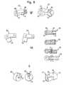
- Fig. 8shows a stabilization system according to a tenth embodiment of the invention, in which the band attachment comprises a separate assembly 65, the rod 11 being attached to both the band attachment, i. in particular to the separate assembly 65, as well as to a common pedicle screw 67 can be fastened or attached.
- the separate structural unit 65is not fastened or fastened directly to the common pedicle screw 67.
- FIGS. 8a and 8beach show a stabilization system in the implanted state.
- the rod 11connects two pedicle screws 67, 69 which comprise the common pedicle screw 67 and each on a vertebra a spine are attached to a rigid stiffening system.
- the tensioned band 23connects three pedicle screws 67, 71, 73 comprising the common pedicle screw 67, the pedicle screws 71, 73 also being respectively attached to a vertebra, to an elastic support system.
- a compressed pressure body 75, 77is arranged in each case, which completely surrounds the band 23 in the circumferential direction.
- the common pedicle screw 67is associated with both the stiffening system and the support system.
- the band 23 and the rod 11are interconnected by the separate assembly 65.
- the separate assembly 65extends substantially perpendicular to the longitudinal extent of the belt 23 or perpendicular to the longitudinal extension of the rod 11, which extend substantially parallel and medial / laterally offset from each other, whereas at least in the embodiments according to Figures 1 to 7, the longitudinal extent of the band and the longitudinal extension of the rod run parallel to each other at least without medial / lateral offset.
- the separate assembly 65may be disposed with respect to the common pedicle screw 67 both on the side of the support system (Fig. 8a) and on the side of the stiffening system (Fig. 8b).
- FIG. 8cshows a separate structural unit 65, which has two tubular passages 79, 81 for fastening the band 23 and for fastening the rod 11.
- the passage 79 for attachment of the rod 11has an upper and a lower half shell 83, 85 which are movable relative to each other by means of a retaining screw 87 in order to clamp the rod 11.
- Perpendicular to the passage 81 for attachment of the belt 23extends an opening 89 into which a pressure element 91, for example a clamping screw, used to clamp the band 23 on the common pedicle screw 67 or inserted.
- the separate assembly 65may also be designed in several parts, in particular, different relative positions of the parts of the separate unit 65 to each other can be realized.
- Such a structural unit 65is shown in each case in the exemplary embodiments according to FIGS. 8d, 8e and 8f.
- the separate assembly 65has a tube-like access or passage 81 for the band 23, which can be fastened by means of the clamping screw 91, which can be inserted through the opening 89.
- the rod 11, which is inserted in the implanted state in the sector-wise open passage 79is analogous to the belt 23 also by means of a clamping screw 93 which is insertable through an opening 95, attachable to the separate assembly 65.
- an axis of rotation 97is provided, so that the parts of the separate assembly 65 are rotated against each other.
- a set relative position of the two parts to each other by means of a locking screw 99can be locked.
- FIGS. 8g and 8hshow further exemplary embodiments of the separate structural unit 65, either in perspective (FIG. 8g) or in a plan view or cross-sectional view (FIG. 8h).
- a one-piece separate unit 65 formed angled or in a multi-part separate unit 65, the distance between the parts of the separate unit 65 to each other by linear displacementcan be changed.
- FIG. 8ishows a separate structural unit 65 into which a non-illustrated rod can be inserted from one side and an unillustrated band from the other, opposite side.
- the separate assembly 65which is effectively designed as a double sleeve, has for this purpose two tubular accesses 79, 81. Furthermore, openings 89, 95 are provided to connect the rod and the band by means not shown clamping screws with the separate unit 65.
- Fig. 9shows a stabilization system according to an eleventh embodiment of the invention, in which the band attachment comprises a separate assembly 65, wherein a non-illustrated rod to the band attachment 65 and the band attachment 65 is fastened or fixed to a common pedicle screw, not shown.
- the rodis not fastened or fastened directly to the common pedicle screw.
- the separate structural unit 65has in each case a central passage 101 which is provided for fastening the separate structural unit 65 to the common pedicle screw. Further, in the separate assembly 65 two each perpendicular to the central passage 101 and mutually parallel passages or entrances 79, 81 are formed for fixing the tape and the rod. For clamping the band, an opening 89 is provided into which a clamping screw, not shown, can be inserted. The passage 79 is slotted and narrowed by means of the common pedicle screw, so that the rod is effectively clamped.
- the band attachmentis a separate assembly 65, wherein the band attachment and the rod 11 are fastened or fixed respectively to the common pedicle screw 67.
- the rod 11is not fastened or fastened directly to the separate structural unit 65.
- the separate assembly 65has a sleeve or access 81 for fastening the band 23 and a fastening ring 103 for attachment to the common pedicle screw 67, the longitudinal axis of the sleeve 81 and the center axis of the fastening ring 103 being substantially perpendicular to one another stand.
- the fastening ring 103may have a recess 105 for the rod 11 (FIG. 10b).
- the band attachmentcomprises the common pedicle screw 67
- the rod 11being attachable or fixed to a separate component 107 which is attachable or fixed to the common pedicle screw 67.
- the rod 11is not fastened or fastened directly to the common pedicle screw 67.
- the separate component 107has two laterally mounted click arms 109 with which the separate component 107 can be attached or attached to the common pedicle screw 67 in the manner of a click closure.
- the click arms 109engage in lateral recesses 111 of the common pedicle screw 67.
- the separate component 107has an access, not shown, in which the rod 11 is inserted or inserted, and an opening 95 into which a clamping screw, not shown, for attaching the rod 11 is inserted.
- an opening 113is provided, through which a fastening screw, not shown, for additional Attachment of the separate component 107 to the common pedicle screw 67 is inserted or inserted.
- the band attachmentcomprises the common pedicle screw 67
- the rod 11can be attached to the common pedicle screw 67 by means of a cantilever 115 extending in the implanted state substantially perpendicular to the longitudinal extension of the band 23 is attached.
- the rod 11is not fastened or fastened directly to the common pedicle screw 67.
- the stabilization system shown in Fig. 12shows a stiffening system at both ends of which is followed by a support system, i. there are two common pedicle screws 67 and two cantilevers 115.
- the cantilevers 115which have an essentially S-shaped configuration, can each have a sector-wise open passage 79 or a passage 79 closed in the circumferential direction at their end assigned to the rod 11.
- a slot 117is formed on the end associated with the common pedicle screw 67, so that different relative positions between the common pedicle screw 67 and the rod 11 are possible.
- the longitudinal extent of the rod 11 and the longitudinal extension of the band 23are parallel and medially / laterally offset from one another.
- the band attachmentcomprises the common pedicle screw 67, wherein the rod 11 is fastened or fixed to the common pedicle screw 67 and the common Pedicle screw 67 has a common passage 119 for the band 23 and the rod 11.
- the band 23 and the rod 11are arranged side by side or one above the other within the common passage 119 of the common pedicle screw 67.
- the band 23 and the rod 11are pressed together by means of a clamping screw, not shown, which is insertable or inserted through an opening formed in the common pedicle screw 67 opening 121, so that both the band 23 and the rod 11 are clamped effectively.
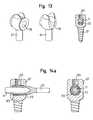
- Fig. 14shows a stabilization system according to a sixteenth embodiment of the invention.
- the embodiment of FIG. 14has analogous to the embodiment of FIG. 13, a common passage 119 for the band 23 and the rod 11 and an opening 121 for insertion of a clamping screw.
- the band 23in contrast to the embodiment according to FIG. 13, the band 23 can be put over or pushed over the rod 11.
- a sleeve 123can be inserted or inserted, which in turn surrounds the band 23. Otherwise, the band 23 and the rod 11 can be clamped analogously to the embodiment in FIG. 13.
- Fig. 14ban embodiment is shown, in which the end 21 of the band 23 is inserted or inserted into the rod 11 similar to FIGS. 1 to 7, wherein by means of a clamping screw 141, through an opening 143 in the common pedicle screw 67 is inserted or introduced, the band 23 and the rod 11 are clamped.
- the common pedicle screw 67is formed like a tuning fork at its upper end, so that between two prongs 149 a receptacle 139 is formed, in which a rod is inserted or inserted.
- the support of the rod on the common pedicle screw 67by means of a clamping screw 141 which is inserted or inserted into drill portions 143 of the two prongs 149, wherein the drill portions 143 each have an internal thread.
- the end 13 of the rod 11, which is designed for connection to the end 21 of the band 23,may have a diameter which is greater than that of a middle part 15 of the rod 11 (FIG. 14d).
- the band 23is connected or connected to the rod 11 by means of a clamping screw 137, which is insertable or inserted through an opening 133 in the rod 11.
- guide meansfor example one or more round or angular pins 145, are formed on the rod 11 or on the head 13 of the rod 11 ( 14d, 14e, 14g) which correspond to corresponding guide means of the common pedicle screw 67 (FIGS. 14c, 14f), for example one or more recesses, grooves or grooves 147, which in particular correspond to the drill sections 143 of the two prongs 149 (FIGS. 14c ) intervene.
- At least one perpendicular to the longitudinal axis of the rod 11 oriented, in particular plate-shaped flange 151may be provided (Fig. 14e, 14g, 14h), which is connected to the rod 11 and a correct positioning of the rod 11 with respect to the common pedicle screw 67 allowed or provides guidance in assembling the stabilization system.
- the flange 151as the conclusion of End 13 of the rod 11 designed, the flange can simultaneously serve as a stop 151 for a pressure body 75 of a support system of the stabilization system.
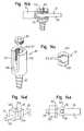
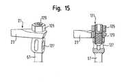
- the band attachmentcomprises the common pedicle screw 67, wherein an unillustrated rod is fastened or fixed to the common pedicle screw 67 and the band 23 between a pressure member, in particular a nut 125, and the common pedicle screw 67 is clamped or clamped, wherein the common pedicle screw 67 has a passage 127 for the rod.
- the inserted into the passage 127 rodis clamped by means of a threaded pin 129 which has a continuous external thread and is inserted or inserted through an opening 121 in the common pedicle screw 67, effectively clamped.
- a threaded pin 129which has a continuous external thread and is inserted or inserted through an opening 121 in the common pedicle screw 67, effectively clamped.
- the nut 125is placed to clamp the band 23 between the common pedicle screw 67 and the nut 125.
- the clamped end 21 of the belt 23is designed for this purpose as a loop into which the threaded pin 129 engages.
Landscapes
- Health & Medical Sciences (AREA)
- Orthopedic Medicine & Surgery (AREA)
- Life Sciences & Earth Sciences (AREA)
- Neurology (AREA)
- Surgery (AREA)
- Heart & Thoracic Surgery (AREA)
- Engineering & Computer Science (AREA)
- Biomedical Technology (AREA)
- Nuclear Medicine, Radiotherapy & Molecular Imaging (AREA)
- Medical Informatics (AREA)
- Molecular Biology (AREA)
- Animal Behavior & Ethology (AREA)
- General Health & Medical Sciences (AREA)
- Public Health (AREA)
- Veterinary Medicine (AREA)
- Surgical Instruments (AREA)
- Prostheses (AREA)
- Dowels (AREA)
Abstract
Description
Translated fromGermanDie Erfindung betrifft ein intervertebrales Stabilisierungssystem für wenigstens drei Wirbel.The invention relates to an intervertebral stabilization system for at least three vertebrae.
Bei Deformationen oder degenerativen Veränderungen der Wirbelsäule kann es nötig sein, das jeweils betroffene instabile Wirbelsäulensegment operativ zu stabilisieren.Deformation or degenerative changes of the spine may require surgical stabilization of the affected unstable spinal column segment.
Hierfür ist es bekannt, das betroffene Wirbelsäulensegment zu versteifen. Bei einer derartigen partiellen Wirbelsäulenversteifung werden üblicherweise die Bandscheiben zumindest teilweise entfernt, Knochengewebe zwischen die zu versteifenden Wirbel eingelagert und die zu versteifenden Wirbel mittels Schrauben und zumindest eines Stabes starr miteinander verbunden. Die Versteifung des Wirbelsäulensegments bedingt jedoch, dass die benachbarten Wirbel bei Beuge- und Streckbewegungen der Wirbelsäule stärker als vor der Versteifung beansprucht werden.For this it is known to stiffen the affected spine segment. In such a partial spinal fusion usually the intervertebral discs are usually at least partially removed, embedded bone tissue between the vertebrae to be stiffened and rigidly connected to the stiffening vertebrae by means of screws and at least one rod. The stiffening of the spinal segment, however, requires that the adjacent vertebrae are stressed more strongly during flexion and extension movements of the spine than before the stiffening.
Alternativ kommt neuerdings "bei leichteren Fällen", insbesondere noch bevor ein Bandscheibenvorfall auftritt, ein Implantat zum Einsatz, das das betroffene Wirbelsäulensegment von posterior stützt, aber nicht versteift und so die Beweglichkeit der betroffenen Wirbel weitestgehend erhält. Dabei wird zwischen an den Wirbeln befestigten Schrauben ein elastisches Band mit biegsamen Abstandshaltern eingesetzt. Das elastische Band begrenzt die Beugebewegung, während die Abstandshalter die Streckbewegung limitieren.Alternatively, more recently, "in lighter cases", especially before a herniated disc occurs, an implant is used, which supports the affected spine segment of posterior, but not stiffened and so largely preserves the mobility of the affected vertebrae. An elastic band with flexible spacers is used between screws fastened to the vertebrae. The elastic band limits the bending movement, while the spacers limit the stretching movement.
Der Erfindung liegt die Aufgabe zugrunde, eine Vorrichtung der eingangs genannten Art zu schaffen, die dazu ausgelegt ist, ein instabiles Wirbelsäulensegment derart zu versteifen, dass bei Beuge- und Streckbewegungen die Wirbelsäule möglichst wenig beansprucht wird, insbesondere um weitere Operationen zu verhindern oder zumindest weitmöglichst hinauszuzögern.The invention has for its object to provide a device of the type mentioned, which is designed to stiffen an unstable spine segment such that during flexion and extension movements, the spine is subjected as little as possible, in particular to prevent further operations or at least as far as possible delay.
Die Lösung dieser Aufgabe erfolgt durch die Merkmale des Anspruchs 1 und insbesondere dadurch, dass an den Wirbeln befestigbare Pedikelschrauben, ein Stab zum Verbinden von zumindest zwei Pedikelschrauben zu einem starren Versteifungssystem und ein auf Zug vorspannbares Band, das im implantierten Zustand des Stabilisierungssystems von wenigstens einem zwischen zwei benachbarten Pedikelschrauben angeordneten komprimierbaren Druckkörpern umgeben ist, zum Verbinden der Pedikelschrauben zu einem elastischen Stützsystem vorgesehen sind, wobei eine gemeinsame Pedikelschraube sowohl dem Versteifungssystem als auch dem Stützsystem zugeordnet und das Band mittels einer Bandbefestigung mit dem Stab verbindbar oder verbunden ist.The solution of this object is achieved by the features of claim 1 and in particular by the fact that attached to the vertebrae pedicle screws, a rod for connecting at least two pedicle screws to a rigid stiffening system and a zugspannbares on train band in the implanted state of the stabilization system of at least one surrounded by two adjacent pedicle screws arranged compressible pressure bodies, are provided for connecting the pedicle screws to an elastic support system, wherein a common pedicle screw both the stiffening system and the support system assigned and the band is connected or connected by means of a band attachment to the rod.
Die Erfindung zeichnet sich folglich dadurch aus, dass das aus dem Stand der Technik bekannte starre Versteifungssystem, das den Stab umfasst, mit dem ebenfalls aus dem Stand der Technik bekannten elastischen Stützsystem, das das Band und den Druckkörper umfasst, kombiniert wird. Das bislang alternativ zu dem bekannten starren Versteifungssystem verwendete elastische Stützsystem wird erfindungsgemäß nun gemeinsam mit dem starren Versteifungssystem zur Stabilisierung eines instabilen Wirbelsäulensegments eingesetzt.The invention is thus characterized in that the known from the prior art rigid stiffening system comprising the rod is combined with the also known from the prior art elastic support system comprising the band and the pressure body. The elastic support system previously used as an alternative to the known rigid stiffening system according to the invention is now used together with the rigid stiffening system for stabilizing an unstable spinal column segment.
Der Stab des Versteifungssystems ist zur Versteifung eines zumindest zwei Wirbel umfassenden instabilen Wirbelsäulensegments ausgelegt. Das Band, das im implantierten Zustand des Stabilisierungssystems mit dem Stab verbunden und im nicht implantierten Zustand mit dem Stab verbunden oder verbindbar ist, wird zur Stützung zumindest eines an das versteifte Wirbelsäulensegment angrenzenden Wirbels verwendet. Der Stab und das Band sind mittels der Pedikelschrauben an den zu stabilisierenden Wirbeln befestigt.The rod of the stiffening system is designed for stiffening an unstable spinal column segment comprising at least two vertebrae. The Band connected to the rod in the implanted state of the stabilization system and connected or connectable to the rod in the un-implanted state is used to support at least one vertebra adjacent to the stiffened spinal column segment. The rod and the band are attached to the vertebrae to be stabilized by means of the pedicle screws.
Vorzugsweise sind zumindest zwei Versteifungssysteme, insbesondere zwei Stäbe, vorgesehen, die im implantierten Zustand des Stabilisierungssystems links und rechts der Dornfortsätze der betroffenen Wirbel angeordnet sind, wobei bevorzugt die beiden Versteifungssysteme miteinander verbindbar oder verbunden sind. Ferner können mehrere Stützsysteme vorgesehen sein. Insbesondere können für das, für mehrere oder für jedes Versteifungssystem zwei Stützsysteme vorgesehen sein, die jeweils an ein Ende des Versteifungssystems anschließen. Grundsätzlich können auch mehrere Versteifungssysteme und Stützsysteme vorgesehen sein, die im implantierten Zustand alternierend miteinander verbunden sind.Preferably, at least two stiffening systems, in particular two rods, are provided, which are arranged in the implanted state of the stabilization system left and right of the spinous processes of the vertebrae concerned, wherein preferably the two stiffening systems are connected or connected. Furthermore, a plurality of support systems may be provided. In particular, two support systems may be provided for, for several or for each stiffening system, each connecting to one end of the stiffening system. In principle, it is also possible to provide a plurality of stiffening systems and support systems which are alternately connected to one another in the implanted state.
Das Band des Stützsystems ist im implantierten Zustand des Stabilisierungssystems auf Zug vorgespannt. Der Druckkörper hingegen befindet sich in einem komprimierten Zustand, d.h. er ist auf Druck vorgespannt. Der Stab und das Band sind dabei über eine Bandbefestigung miteinander verbunden, d.h. das Band ist an dem Stab befestigt oder umgekehrt. Die gemeinsame Pedikelschraube, an der oder in deren Nähe im implantierten Zustand des Stabilisierungssystems die Verbindung des Bands mit dem Stab üblicherweise ausgebildet ist, wird von dem starren Versteifungssystem und dem elastischen Stützsystem gleichermaßen verwendet. Ist die Bandbefestigung etwa mittig zwischen zwei Pedikelschrauben angeordnet, kann eine beliebige der beiden Pedikelschrauben als die gemeinsame Pedikelschraube betrachtet werden.The band of the support system is biased to train in the implanted state of the stabilization system. The pressure body, however, is in a compressed state, ie it is biased to pressure. The rod and the band are connected to each other via a band attachment, ie the band is attached to the rod or vice versa. The common pedicle screw, at or near which, in the implanted state of the stabilization system, the connection of the ligament to the rod is usually formed, is used equally by the rigid stiffening system and the elastic support system. If the band attachment is located approximately midway between two pedicle screws, any one of the two pedicle screws may be considered the common pedicle screw.
Durch das elastische Stützsystem, das sich als Verlängerung des starren Versteifungssystems an dieses anschließt, bzw. durch die elastischen Stützsysteme, die sich an beiden Seiten des starren Versteifungssystems an dieses anschließen, können der oder die an die durch das Versteifungssystem starr miteinander verbundenen Wirbel anschließenden Wirbel gestützt werden, so dass diese benachbarten Wirbel bei Beuge- und Streckbewegungen der Wirbelsäule keinen erhöhten Belastungen ausgesetzt sind.By the elastic support system, which adjoins this as an extension of the rigid stiffening system, or by the elastic support systems, which adjoin this on both sides of the rigid stiffening system, the one or more can be connected to the rigidly connected by the stiffening system vortex vortex be supported so that these adjacent vertebrae are not subjected to increased loads during flexion and extension movements of the spine.
Vorteilhafte Ausführungsformen der Erfindung sind auch in den Unteransprüchen, der Beschreibung sowie der Zeichnung angegeben.Advantageous embodiments of the invention are also specified in the subclaims, the description and the drawing.
Vorzugsweise ist die Bandbefestigung als Klemmeinrichtung zur Klemmung des Bands ausgebildet. Durch die Klemmkräfte der als Klemmeinrichtung ausgelegten Bandbefestigung kann das im implantierten Zustand des Stabilisierungssystems unter Zugkraft stehende Band besonders sicher und zuverlässig gehalten werden.Preferably, the band attachment is designed as a clamping device for clamping the band. Due to the clamping forces of the band fastening designed as a clamping device, the band under tensile force in the implanted state of the stabilization system can be kept particularly secure and reliable.
Es ist weiterhin bevorzugt, dass die Bandbefestigung ein Ende des Stabs, eine separate Baueinheit und/oder die gemeinsame Pedikelschraube umfasst.It is further preferred that the band attachment comprises one end of the rod, a separate assembly and / or the common pedicle screw.
Die Erfindung wird im Folgenden beispielhaft unter Bezugnahme auf die Zeichnung, die verschiedene Ausführungsformen umfasst, deren jeweiligen Merkmale - soweit sinnvoll - beliebig miteinander kombinierbar sind, beschrieben. Es zeigen:
- Fig. 1 bis 7
- Bandbefestigungen eines erfindungsgemäßen Stabilisierungssystems, die jeweils ein Ende des Stabs umfassen,
- Fig. 8 bis 10
- Bandbefestigungen eines erfindungsgemäßen Stabilisierungssystems, die jeweils eine separate Baueinheit umfassen, und
- Fig. 11 bis 15
- Bandbefestigungen eines erfindungsgemäßen Stabilisierungssystems, die jeweils eine gemeinsame Pedikelschraube umfassen.
- Fig. 1 to 7
- Band fastenings of a stabilization system according to the invention, each comprising one end of the rod,
- Fig. 8 to 10
- Bandbefestigungen a stabilization system according to the invention, each comprising a separate unit, and
- Fig. 11 to 15
- Band fastenings of a stabilization system according to the invention, each comprising a common pedicle screw.
Die nachstehend erläuterten Ausführungsformen zeigen jeweils nur den Teil des Stabilisierungssystems, der für die Beschreibung der Verbindung zwischen dem Stab des Versteifungssystems und dem Band des Stützsystems notwendig ist. Dabei sind gleiche oder einander entsprechende Bestandteile der verschiedenen Ausführungsformen der Erfindung jeweils mit denselben Bezugszeichen bezeichnet.The embodiments explained below each show only that part of the stabilization system which is necessary for the description of the connection between the bar of the stiffening system and the band of the support system. In this case, the same or corresponding components of the various embodiments of the invention are denoted by the same reference numerals.
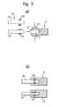
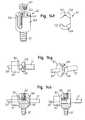
Fig. 1 zeigt ein Stabilisierungssystem gemäß einer ersten Ausführungsform der Erfindung mit einem aus Metall gefertigten starren Stab 11 eines ansonsten nicht dargestellten starren Versteifungssystems, wobei der Stab 11 ein Ende 13 aufweist, das einen größeren Durchmesser besitzt als das Mittelteil 15 des Stabs 11. Das als Kopf 13 ausgebildete Ende des Stabs 11, das gleichzeitig als Anschlag für einen nicht dargestellten Druckkörper dienen kann, ist zumindest Teil einer Bandbefestigung und weist einen im Wesentlichen zylinderartigen Hohlraum 17 auf, in den über eine Bandeintrittsöffnung 19 ein Ende 21 eines elastischen, beispielsweise aus Kunststoff gefertigten Bands 23 eines ansonsten nicht dargestellten elastischen Stützsystems einführbar oder eingeführt ist.Fig. 1 shows a stabilization system according to a first embodiment of the invention with a made of metal
Die Bandbefestigung umfasst ferner ein in den Hohlraum 17 längs der Einführrichtung 25 des Endes 21 des Bands 23 einführbares (Fig. 1a) oder eingeführtes (Fig. 1c), in Umfangrichtung geschlossenes hülsenartiges Klemmelement 27, das auf das Ende 21 des Bands 23 aufgeschoben ist und zur Klemmung des in den Hohlraum 17 des Stabs 11 eingeführten Endes 21 des Bands 23 mit dem Kopf 13 des Stabs 11 ausgelegt ist. Das hülsenartige Klemmelement 27 kann auch als Klemmhülse oder Spannring bezeichnet werden.The band fastening furthermore comprises an insertable into the
Die Klemmhülse 27 ist im nicht in den Hohlraum 17 des Stabs 11 eingeführten Zustand an ihrer Außenseite konisch zulaufend ausgebildet, wobei die Wandstärke der Klemmhülse 27 in Richtung des den größeren Außendurchmesser aufweisenden Endes zunimmt. Gemäß Fig. 1d kann an der Innenseite der Klemmhülse 27 an dem den größeren Außendurchmesser aufweisenden Ende ein in Umfangsrichtung umlaufender, nach innen gerichteter, den Innendurchmesser der Klemmhülse 27 verengender Vorsprung 29 ausgebildet sein. Gemäß Fig. 1e kann das Klemmelement 27 insbesondere auf zwei gegenüberliegenden Seiten geschlitzt sein. Grundsätzlich kann die Klemmhülse sowohl einen Vorsprung aufweisen als auch geschlitzt sein.The
In den Fig. 1a bis 1c ist das Verbinden des Stabs 11 mit dem Band 23 gezeigt. Zunächst wird die Klemmhülse 27 auf das in den Hohlraum 17 des Stabs 11 einzuführende Ende 21 des Bands 23 derart aufgeschoben, dass das den größeren Außendurchmesser aufweisende Ende der konischen Klemmhülse 27 der Mitte des Bands 23 zugewandt ist (Fig. 1a). Danach wird das mit der Klemmhülse 25 versehene Ende 21 des Bands 23 mittels eines geeigneten Werkzeugs längs der Einführrichtung 25 in den Hohlraum 17 des Kopfes 13 des Stabs 11 eingepresst (Fig. 1b).In FIGS. 1 a to 1 c, the connection of the
Dabei wird das den größeren Außendurchmesser aufweisende Ende der Klemmhülse 27 auf den Innendurchmesser des zylinderartigen Hohlraums 17 des Stabs 11, der zumindest im Wesentlichen dem kleineren Außendurchmesser des anderen Endes der Klemmhülse 27 entspricht, zusammengedrückt. Im zusammengesetzten Zustand (Fig. 1c) nimmt der Innendurchmesser der Klemmhülse 27 in Richtung des ursprünglich einen größeren Außendurchmesser aufweisenden Endes aufgrund der in dieser Richtung zunehmenden Wandstärke der Klemmhülse 27 ab, d.h. der Durchgang der Klemmhülse 27 verengt sich in Richtung der Bandeintrittsöffnung 19 des Hohlraums 17 des Kopfes 13 des Stabs 11, so dass das Band 23 wirksam geklemmt wird.In this case, the larger outer diameter end of the
Durch den in Fig. 1d dargestellten Vorsprung 29 kann die Klemmkraft der Bandbefestigung zusätzlich verstärkt werden. Eine geschlitzte Klemmhülse 27 (Fig. 1e) bietet den Vorteil, dass beim Einführen der Klemmhülse 27 in den Hohlraum 17 des Kopfes 13 des Stabs 11 zusätzlicher Platz für Materialverformungen zur Verfügung steht, so dass der Einpressvorgang insgesamt mit geringerem Kraftaufwand durchgeführt werden kann.By the
Fig. 2 zeigt ein Stabilisierungssystem gemäß einer zweiten Ausführungsform der Erfindung. Im Gegensatz zu der Ausführungsform in Fig. 1 umfasst die Bandbefestigung gemäß Fig. 2 zwei Klemmhülsen 27, 31, die gegeneinander verspannt sind.Fig. 2 shows a stabilization system according to a second embodiment of the invention. In contrast to the embodiment in Fig. 1, the band attachment according to FIG. 2 comprises two clamping
In Analogie zu Fig. 1 ist bei dem Ausführungsbeispiel gemäß den Fig. 2a und 2b die erste Klemmhülse 27 auf das in den Hohlraum 17 des Stabs 11 einzuführende Ende 21 des Bands 23 derart aufgeschoben, dass das den größeren Außendurchmesser aufweisende Ende der konischen ersten Klemmhülse 27 der Mitte des Bands 23 zugewandt ist (Fig. 2a). Die zweite Klemmhülse 31, die als Kegelpressring dient, ist spiegelbildlich zu der ersten Klemmhülse 27 bezüglich einer Ebene, die senkrecht auf der Einführrichtung 25 steht, in den Hohlraum 17 des Kopfes 13 des Stabs 11 eingepresst (Fig. 2a). Zum Verbinden des Bands 23 mit dem Stab 11 wird die erste Klemmhülse 27 längs der Einführrichtung 25 in den Hohlraum 17 des Kopfes 13 des Stabs 11 eingepresst, wobei die erste Klemmhülse 27 mit der zweiten Klemmhülse 31 verspannt. Die erste Klemmhülse 27 wird dabei derart verformt, dass das Band 23 wirksam eingeklemmt ist (Fig. 2b). Grundsätzlich können auch mehrere Kegelpressringe vorgesehen sein.In analogy to FIG. 1, in the exemplary embodiment according to FIGS. 2 a and 2 b, the
Bei dem Ausführungsbeispiel gemäß den Fig. 2c und 2d sind die beiden Klemmhülsen 27, 31 hinsichtlich ihrer Orientierungen gegenüber dem Ausführungsbeispiel gemäß den Fig. 2a und 2b vertauscht, wobei die erste Klemmhülse 27 im nicht eingeführten Zustand auf das Ende 21 des Bands 23 aufgepresst ist (Fig. 2c). Beim Zusammensetzen wird das mit der ersten Klemmhülse 27 versehene Ende 21 des Bands 23 längs der Einführrichtung 25 in den Hohlraum 17 des Kopfes 13 des Stabs 11 eingeführt. Anschließend wird die zweite Klemmhülse 31 längs der Einführrichtung 25 in den Hohlraum eingepresst (Fig. 2d).In the embodiment according to FIGS. 2c and 2d, the two clamping
Fig. 3 zeigt ein Stabilisierungssystem gemäß einer dritten Ausführungsform der Erfindung.Fig. 3 shows a stabilization system according to a third embodiment of the invention.
Dabei umfasst die Bandbefestigung des Ausführungsbeispiels gemäß den Fig. 3a bis 3c einen unter Press-Sitz in den Hohlraum 17 quer zur Einführrichtung 25 des Endes 21 des Bands 23 einführbaren Klemmstift 33, der zur Klemmung des in den Hohlraum 17 des Stabs 11 eingeführten Endes des Bands mit dem Kopf 13 des Stabs 11 ausgelegt ist. Der Klemmstift 33, der durch eine Öffnung 35 in den Hohlraum 17 des Stabs 11 eingeführt ist, kann an seiner Spitze, die das eingeführte Ende 21 des Bands 23 radial zu dessen Längserstreckung mit Druck beaufschlagt, rund (Fig. 3a) oder keilförmig (Fig. 3b) ausgebildet sein. Mit einem keilförmigen Klemmstift 33 kann ein größerer Pressdruck auf das eingeklemmte Band 23 erreicht werden.In this case, the band attachment of the embodiment according to FIGS. 3 a to 3 c comprises a press-fit into the
Diametral entgegengesetzt zu der Öffnung 35, durch die der Klemmstift 33 in den Hohlraum 17 eingeführt ist, ist an der den Hohlraum 17 begrenzenden Innenseite des Kopfes 13 des Stabs 11 eine Mulde 37 ausgebildet, in die das Band 23 bei eingepresstem Klemmstift 33 gedrückt wird. Durch die hierdurch geschaffene Umlenkung des Bands 23 kann die Klemmkraft auf das Band 23 zusätzlich erhöht werden. Um das Einführen des Bands 23 zu erleichtern, kann auf das einzuführende Ende 21 des Bands 23 eine als Hülse 39 ausgebildete Einführhilfe aufgesteckt sein (Fig. 3a und 3b). Wie in Fig. 3c zu erkennen ist, können ein, zwei, drei oder beliebig viele Klemmstifte 33, 41, 43 vorgesehen sein.Diametrically opposite to the
Bei dem Ausführungsbeispiel gemäß Fig. 3d umfasst die Bandbefestigung ein Druckelement, beispielsweise eine Klemmschraube 137, das über eine Öffnung 133 quer zur Einführrichtung 25 in den Hohlraum des Kopfs 13 des Stabs 11 einführbar und zum Klemmen des Endes 21 des Bands 23 innerhalb des Kopfs 13 des Stabs 11 ausgelegt ist. Ferner ist eine gegenüber der Bandeintrittsöffnung 19 tiefer liegende Bandaustrittsöffnung 135 vorgesehen, durch die das Ende 21 des Bands 23 aus dem Hohlraum des Stabs 11 wieder ausführbar oder ausgeführt ist. Der nicht in den Kopf 13 eingeführte Teil des Bands 23 ist von einem Druckkörper 75, der auch als Kissen bezeichnet werden kann, umgeben. Der Stabs 11 ist im zusammengesetzten Zustand in eine Aufnahme 139 einer an ihrem oberen Ende stimmgabelartig ausgebildeten gemeinsamen Pedikelschraube 67 eingelegt oder einlegbar und mittels einer Klemmschraube 141 an dieser befestigt oder befestigbar. Das obere Ende der gemeinsamen Pedikelschraube 67 kann aber auch als Durchgang ausgebildet sein.In the embodiment according to FIG. 3d, the band fastening comprises a pressure element, for example a clamping
Fig. 4 zeigt ein Stabilisierungssystem gemäß einer vierten Ausführungsform der Erfindung, bei der sich der Hohlraum 17 zur Bandeintrittsöffnung 19 des Kopfes 13 des Stabs 11 hin verengt. Die Verengung ist dabei bei in den Hohlraum 17 eingeführtem Ende 21 des Bands 23 durch Umformen des Kopfes 13 des Stabs 11 entstanden. Durch die Verengung wird das Band 23 wirksam geklemmt (Fig. 4b, 4f und 4h). Analog zu Fig. 3 kann auch bei der Ausführungsform gemäß Fig. 4 eine Hülse 39 als Einführhilfe für das Ende 21 des Bands 23 verwendet werden, wie in den Fig. 4a und 4b dargestellt ist.4 shows a stabilization system according to a fourth embodiment of the invention, in which the
In dem Ausführungsbeispiel gemäß den Fig. 4a und 4b weist der Kopf 13 des Stabs 11 vor der Umformung eine entgegen der Einführrichtung 25 vorstehende, in Umfangsrichtung des Stabs 11 umlaufende Auskragung 45 auf. Das Umformen der Auskragung 45 von der in Fig. 4a gezeigten Position in die in Fig. 4b gezeigte Position, bei der die Orientierung der Auskragung 45 gewissermaßen um 90° gedreht wird, kann beispielsweise durch Rollpressen (Fig. 4c) oder durch die Verwendung zweier Halbschalen (Fig. 4d) erreicht werden.In the exemplary embodiment according to FIGS. 4 a and 4 b, the
In dem Ausführungsbeispiel gemäß den Fig. 4e und 4f weist der Kopf 13 des Stabs 11 vor der Umformung keine Auskragung auf. Vielmehr wird beim Einpressen des einzuführenden Endes 21 des Bands 23 der die Begrenzung der Bandeintrittsöffnung 19 bildende Bereich des Kopfes 13 des Stabs 11 mittels eines Stempels 131 derart verformt, insbesondere nach innen gedrückt, dass sich der Hohlraum 17 zur Bandeintrittsöffnung 19 des Kopfes 13 des Stabs 11 hin verengt.In the embodiment according to FIGS. 4e and 4f, the
Das Ausführungsbeispiel gemäß den Fig. 4g und 4h zeichnet sich dadurch aus, dass vor der Umformung der Außendurchmesser des Kopfes 13 des Stabs 11 und die damit verbundene Wandstärke des Kopfes 13 im Bereich des Hohlraums 17 in die der Einführrichtung 25 des Bands 23 entgegengesetzte Richtung zunimmt. Beim Umformen des Kopfes 13 des Stabs 11 wird ein Pressring 47, der einen Innendurchmesser aufweist, der im Wesentlichen dem Außendurchmesser des Mittelteils 15 des Stabs 11 entspricht, entgegen der Einführrichtung 25 bewegt. Dabei wird der Kopf 13 des Stabs 11 auf den Innendurchmesser des Pressrings 47 zusammengedrückt, so dass sich der Hohlraum 17 zur Bandeintrittsöffnung 19 des Kopfes 13 hin aufgrund der in dieser Richtung zunehmenden Wandstärke des Kopfes 13 verengt.The embodiment according to FIGS. 4g and 4h is characterized in that, prior to forming, the outer diameter of the
Fig. 5 zeigt ein Stabilisierungssystem gemäß einer fünften Ausführungsform der Erfindung, bei der die Verbindung des Bands 23 mit dem Stab 11 durch Umformen des Kopfes 13 des Stabs 11 entstanden ist. Der Kopf 13 des Stabs 11 sowie der Hohlraum 17 innerhalb des Kopfes 13 sind dabei zumindest vor der Umformung jeweils kugelartig geformt, wobei der Durchmesser der Bandeintrittsöffnung 19 kleiner ist als der in dem Kopf 13 ausgebildete Hohlraum 17. Die Hohlraum 17 ist somit bereits vor der Umformung zur Bandeintrittsöffnung 19 hin verengt.Fig. 5 shows a stabilization system according to a fifth embodiment of the invention, in which the connection of the
Zur Herstellung der Verbindung des Bands 23 mit dem Stab 11 wird zunächst ein Ring 49, insbesondere ein zugespitzter Ring 49', auf das Ende 21 des Bands 23 aufgeschoben (Fig. 5a). Das mit dem Ring 49, 49' versehene Ende 21 des Bands 23 wird dann in den Hohlraum 17 des Kopfes 13 des Stabs 11 eingeführt, woraufhin der Kopf 13 des Stabs 11 und somit auch der Ring 49, 49' zusammengepresst wird, so dass das Band 23 wirksam geklemmt ist (Fig. 5b). Durch das Zuspitzen des Rings 49' kann die auf das Band 23 ausgeübte Presskraft zusätzlich erhöht werden.To produce the connection of the
Fig. 6 zeigt ein Stabilisierungssystem gemäß einer sechsten Ausführungsform der Erfindung. Die Ausführungsform gemäß Fig. 6 entspricht im Wesentlichen der Ausführungsform gemäß Fig. 1, mit dem Unterschied, dass die Bandbefestigung zusätzlich eine insbesondere aus Metall oder Kunststoff bestehende Einlage 51 umfasst, die in das in den Hohlraum des Stabs 11 einführbare (Fig. 6a) oder eingeführte (Fig. 6b) Ende 21 des Bands 23 insbesondere zentrisch eingearbeitet ist und sich längs der Einführrichtung 25 des Bands 23 erstreckt.Fig. 6 shows a stabilization system according to a sixth embodiment of the invention. The embodiment according to FIG. 6 essentially corresponds to the embodiment according to FIG. 1, with the difference that the band fastening additionally comprises an
Die Einlage 51 ist stiftförmig ausgebildet und umfasst einen Kopf 53 und einen Schaft 55, wobei der Durchmesser des Kopfes 53 größer ist als der des Schafts 55. Der Kopf 53 ragt dabei zum Teil aus dem Ende 21 des Bands 23 heraus. Durch die Einlage 51 kann der auf das eingeklemmte Band 23 ausgeübte Pressdruck und somit die Haltekraft der durch die Bandbefestigung ausgebildeten Verbindung zwischen dem Band 23 und dem Stab 11 erhöht werden.The
Fig. 7 zeigt ein Stabilisierungssystem gemäß einer siebten Ausführungsform der Erfindung. In Fig. 7 ist das Band 23 zu einer Vielzahl von Festigkeitsträgern, insbesondere Fasern, aus denen das Band 23 besteht, aufgeweitet und mittels eines Einsatzes 57 in den Hohlraum 17 des Kopfs 13 des Stabs 11 einpressbar (Fig. 7b) oder eingepresst (Fig. 7c). Um die Aufweitung zu erreichen, wird das Ende 21 des Bands 23 mittels eines Bürstenwerkzeugs 59 aufgebürstet (Fig. 7a).Fig. 7 shows a stabilization system according to a seventh embodiment of the invention. In Fig. 7, the
Zum Einpressen wird der Einsatz 57, der in Fig. 7 als Ringeinsatz ausgelegt ist, auf das Band 23 aufgefädelt, und in den Hohlraum 17 des Kopfs 13 eingeführt, so dass die einzelnen Fasern, die in allen Richtungen radial zur Einführrichtung 25 abstehen, zwischen der Vorderseite des Ringeinsatzes 57 und der Begrenzung des Hohlraums 17 eingeklemmt sind. Um die Haltekräfte einer derartigen Verbindung zwischen dem Band 23 und dem Stab 11 zu erhöhen, kann ein zentral positionierter Dorn 61, der entgegen der Einführrichtung 25 in den Hohlraum 17 hineinragt, und eine um den Dorn 61 umlaufende Nase 63, die ebenfalls entgegen der Einführrichtung 25 in den Hohlraum 17 hineinragt, vorgesehen sein (Fig. 7d).For pressing the
Gemäß einer nicht dargestellten achten Ausführungsform der Erfindung ist das in den Hohlraum einführbare oder eingeführte Ende des Bands insbesondere mittels Leim oder Zement verklebt. Hierdurch werden die Fasern des Bandes miteinander verbunden, so dass ein Aneinanderabgleiten der einzelnen Fasern verhindert und somit eine größere Haltekraft für die Verbindung zwischen dem Band und dem Stab erreicht werden kann.According to an eighth embodiment of the invention, not shown, the end of the band which can be inserted or introduced into the cavity is adhesively bonded in particular by means of glue or cement. As a result, the fibers of the band are connected to each other, so that a sliding apart of the individual fibers prevented and thus a greater holding force for the connection between the band and the rod can be achieved.
Gemäß einer nicht dargestellten neunten Ausführungsform der Erfindung weist das in den Hohlraum einführbare oder eingeführte Ende des Bands eine Form auf, die durch Schmelzen, Formen und anschließendes Aushärten entstanden ist. Die Form kann insbesondere derart sein, dass das Ende des Bands nach Aushärten als Widerhaken ausgelegt ist.According to a ninth embodiment of the invention, not shown, the end of the band which can be introduced or inserted into the cavity has a shape which has been formed by melting, shaping and subsequent hardening. In particular, the mold may be such that the end of the band is designed as a barb after curing.
Fig. 8 zeigt ein Stabilisierungssystem gemäß einer zehnten Ausführungsform der Erfindung, bei der die Bandbefestigung eine separate Baueinheit 65 umfasst, wobei der Stab 11 sowohl an der Bandbefestigung, d.h. insbesondere an der separaten Baueinheit 65, als auch an einer gemeinsamen Pedikelschraube 67 befestigbar oder befestigt ist. Insbesondere ist die separate Baueinheit 65 dabei nicht unmittelbar an der gemeinsamen Pedikelschraube 67 befestigbar oder befestigt.Fig. 8 shows a stabilization system according to a tenth embodiment of the invention, in which the band attachment comprises a
Die Fig. 8a und 8b zeigen jeweils ein Stabilisierungssystem im implantierten Zustand. Der Stab 11 verbindet zwei Pedikelschrauben 67, 69, die die gemeinsame Pedikelschraube 67 umfassen und jeweils an einem Wirbel einer Wirbelsäule befestigt sind, zu einem starren Versteifungssystem. Das Band 23, das auf Zug vorgespannt ist, verbindet drei Pedikelschrauben 67, 71, 73, die die gemeinsame Pedikelschraube 67 umfassen, wobei die Pedikelschrauben 71, 73 ebenfalls jeweils an einem Wirbel befestigt sind, zu einem elastischen Stützsystem. Zwischen den Pedikelschrauben 67 und 71 sowie zwischen den Pedikelschrauben 71 und 73 ist jeweils ein komprimierter Druckkörper 75, 77 angeordnet, die das Band 23 in Umfangsrichtung jeweils vollständig umgeben. Die gemeinsame Pedikelschraube 67 ist sowohl dem Versteifungssystem als auch dem Stützsystem zugeordnet.FIGS. 8a and 8b each show a stabilization system in the implanted state. The
Das Band 23 und der Stab 11 sind durch die separate Baueinheit 65 miteinander verbunden. Die separate Baueinheit 65 erstreckt sich im Wesentlichen senkrecht zu der Längserstreckung des Bands 23 bzw. senkrecht zu der Längserstreckung des Stabs 11, die im Wesentlichen parallel und medial/lateral versetzt zueinander verlaufen, wohingegen wenigstens bei den Ausführungsformen gemäß den Figuren 1 bis 7 die Längserstreckung des Bands und die Längserstreckung des Stabs zumindest ohne medialen/lateralen Versatz parallel zueinander verlaufen. Gemäß Fig. 8 kann die separate Baueinheit 65 bezüglich der gemeinsamen Pedikelschraube 67 sowohl auf der Seite des Stützsystems (Fig. 8a) als auch auf der Seite des Versteifungssystems (Fig. 8b) angeordnet sein.The
Das Ausführungsbeispiel gemäß Fig. 8c zeigt eine separate Baueinheit 65, die zwei rohrartige Durchgänge 79, 81 zur Befestigung des Bands 23 und zur Befestigung des Stabs 11 aufweist. Der Durchgang 79 zur Befestigung des Stabs 11 weist eine obere und eine untere Halbschale 83, 85 auf, die mittels einer Halteschraube 87 relativ zueinander bewegbar sind, um den Stab 11 einzuklemmen. Senkrecht zu dem Durchgang 81 zur Befestigung des Bands 23 verläuft eine Öffnung 89, in die ein Druckelement 91, beispielsweise eine Klemmschraube, zum Klemmen des Bands 23 an der gemeinsamen Pedikelschraube 67 einsetzbar oder eingesetzt ist.The embodiment according to FIG. 8c shows a separate
Die separate Baueinheit 65 kann auch mehrteilig ausgeführt sein, wobei insbesondere unterschiedliche Relativstellungen der Teile der separaten Baueinheit 65 zueinander realisierbar sind. Eine derartige Baueinheit 65 ist jeweils in den Ausführungsbeispielen gemäß den Fig. 8d, 8e und 8f gezeigt. Die separate Baueinheit 65 weist einen rohrartigen Zugang bzw. Durchgang 81 für das Band 23 auf, das mittels der Klemmschraube 91, die durch die Öffnung 89 einführbar ist, befestigbar ist. Der Stab 11, der im implantierten Zustand in den sektorweise offenen Durchgang 79 eingeführt ist, ist analog zu dem Band 23 ebenfalls mittels einer Klemmschraube 93, die durch eine Öffnung 95 einführbar ist, an der separaten Baueinheit 65 befestigbar. Zwischen dem einen Teil der separaten Baueinheit 65, in dem der Zugang bzw. Durchgang 81 ausgebildet ist, und dem anderen Teil der separaten Baueinheit 65, in dem der Durchgang 79 ausgebildet ist, ist eine Drehachse 97 vorgesehen, so dass die Teile der separaten Baueinheit 65 gegeneinander verdrehbar sind. Eine eingestellte Relativstellung der beiden Teile zueinander ist mittels einer Feststellschraube 99 arretierbar.The
In den Fig. 8g und 8h sind weitere Ausführungsbeispiele der separaten Baueinheit 65 entweder perspektivisch (Fig. 8g) oder in einer Draufsicht bzw. Querschnittsansicht (Fig. 8h) dargestellt. Insbesondere wird deutlich, dass eine einteilige separate Baueinheit 65 gewinkelt ausgebildet bzw. bei einer mehrteiligen separaten Baueinheit 65 der Abstand der Teile der separaten Baueinheit 65 zueinander durch lineare Verschiebung veränderbar sein kann.FIGS. 8g and 8h show further exemplary embodiments of the separate
Das Ausführungsbeispiel gemäß 8i zeigt eine separate Baueinheit 65, in die von der einen Seite ein nicht dargestellter Stab und von der anderen, gegenüberliegenden Seite ein nicht dargestelltes Band einführbar ist. Die separate Baueinheit 65, die gewissermaßen als Doppelhülse ausgebildet ist, weist hierfür zwei rohrartige Zugänge 79, 81 auf. Weiterhin sind Öffnungen 89, 95 vorgesehen, um den Stab und das Band mittels nicht dargestellter Klemmschrauben mit der separaten Baueinheit 65 zu verbinden.The embodiment according to FIG. 8i shows a separate
Fig. 9 zeigt ein Stabilisierungssystem gemäß einer elften Ausführungsform der Erfindung, bei der die Bandbefestigung eine separate Baueinheit 65 umfasst, wobei ein nicht dargestellter Stab an der Bandbefestigung 65 und die Bandbefestigung 65 an einer nicht dargestellten gemeinsamen Pedikelschraube befestigbar oder befestigt ist. Insbesondere ist der Stab dabei nicht unmittelbar an der gemeinsamen Pedikelschraube befestigbar oder befestigt.Fig. 9 shows a stabilization system according to an eleventh embodiment of the invention, in which the band attachment comprises a
In dem Ausführungsbeispiel gemäß den Fig. 9a und 9b weist die separate Baueinheit 65 jeweils einen zentralen Durchgang 101 auf, der zur Befestigung der separaten Baueinheit 65 an der gemeinsamen Pedikelschraube vorgesehen ist. Ferner sind in der separaten Baueinheit 65 zwei jeweils senkrecht zu dem zentralen Durchgang 101 und parallel zueinander verlaufende Durchgänge bzw. Zugänge 79, 81 zur Befestigung des Bands und des Stabs ausgebildet. Zur Klemmung des Bands ist eine Öffnung 89 vorgesehen, in die eine nicht dargestellte Klemmschraube einsetzbar ist. Der Durchgang 79 ist geschlitzt und mittels der gemeinsamen Pedikelschraube verengbar, so dass der Stab wirksam einklemmbar ist.In the exemplary embodiment according to FIGS. 9a and 9b, the separate
Fig. 10 zeigt ein Stabilisierungssystem gemäß einer zwölften Ausführungsform der Erfindung, bei der die Bandbefestigung eine separate Baueinheit 65 umfasst, wobei die Bandbefestigung und der Stab 11 jeweils an der gemeinsamen Pedikelschraube 67 befestigbar oder befestigt sind. Insbesondere ist der Stab 11 dabei nicht unmittelbar an der separaten Baueinheit 65 befestigbar oder befestigt.10 shows a stabilization system according to a twelfth embodiment of the invention, in which the band attachment is a
Die separate Baueinheit 65 gemäß Fig. 10a weist eine Hülse bzw. einen Zugang 81 zur Befestigung des Bands 23 und einen Befestigungsring 103 zur Befestigung an der gemeinsamen Pedikelschraube 67 auf, wobei die Längsachse der Hülse 81 und die Mittelachse des Befestigungsrings 103 im Wesentlichen senkrecht aufeinander stehen. Der Befestigungsring 103 kann eine Aussparung 105 für den Stab 11 aufweisen (Fig. 10b).The
Fig. 11 zeigt ein Stabilisierungssystem gemäß einer dreizehnten Ausführungsform der Erfindung, bei der die Bandbefestigung die gemeinsame Pedikelschraube 67 umfasst, wobei der Stab 11 an einem separaten Bauteil 107 befestigbar oder befestigt ist, das an der gemeinsamen Pedikelschraube 67 befestigbar oder befestigt ist. Insbesondere ist der Stab 11 dabei nicht unmittelbar an der gemeinsamen Pedikelschraube 67 befestigbar oder befestigt.11 shows a stabilization system according to a thirteenth embodiment of the invention in which the band attachment comprises the
Das separate Bauteil 107 gemäß Fig. 11 weist zwei seitlich angebrachte Klickarme 109 auf, mit denen das separate Bauteil 107 nach Art eines Klickverschlusses an der gemeinsamen Pedikelschraube 67 befestigbar oder befestigt ist. Zur Befestigung rasten die Klickarme 109 in seitliche Vertiefungen 111 der gemeinsamen Pedikelschraube 67 ein. Darüber hinaus weist das separate Bauteil 107 einen nicht dargestellten Zugang, in den der Stab 11 einführbar oder eingeführt ist, und eine Öffnung 95 auf, in die eine nicht dargestellte Klemmschraube zur Befestigung des Stabs 11 einführbar ist. Darüber hinaus ist eine Öffnung 113 vorgesehen, durch die eine nicht dargestellte Befestigungsschraube zur zusätzlichen Befestigung des separaten Bauteils 107 an der gemeinsamen Pedikelschraube 67 einführbar oder eingeführt ist.The
Fig. 12 zeigt ein Stabilisierungssystem gemäß einer vierzehnten Ausführungsform der Erfindung, bei der die Bandbefestigung die gemeinsame Pedikelschraube 67 umfasst, wobei der Stab 11 mittels eines im implantierten Zustand im Wesentlichen senkrecht zur Längserstreckung des Bands 23 verlaufenden Auslegers 115 an der gemeinsamen Pedikelschraube 67 befestigbar oder befestigt ist. Insbesondere ist der Stab 11 dabei nicht unmittelbar an der gemeinsamen Pedikelschraube 67 befestigbar oder befestigt.12 shows a stabilization system according to a fourteenth embodiment of the invention, in which the band attachment comprises the
Das in Fig. 12 dargestellte Stabilisierungssystem zeigt ein Versteifungssystem, an dessen beiden Enden jeweils ein Stützsystem anschließt, d.h. es sind zwei gemeinsame Pedikelschrauben 67 und zwei Ausleger 115 vorhanden. Die im Wesentlichen eine S-förmige Gestalt aufweisenden Ausleger 115 können jeweils an ihrem dem Stab 11 zugeordneten Ende einen sektorweise offenen Durchgang 79 oder einen in Umfangsrichtung geschlossenen Durchgang 79 aufweisen. Zur Befestigung eines Auslegers 115 an einer gemeinsamen Pedikelschraube 67 ist an dem der gemeinsamen Pedikelschraube 67 zugeordneten Ende ein Langloch 117 ausgebildet, so dass verschiedene Relativstellungen zwischen der gemeinsamen Pedikelschraube 67 und dem Stab 11 möglich sind. Die Längserstreckung des Stabs 11 und die Längserstreckung des Bands 23 verlaufen parallel und medial/lateral versetzt zueinander.The stabilization system shown in Fig. 12 shows a stiffening system at both ends of which is followed by a support system, i. there are two common pedicle screws 67 and two
Fig. 13 zeigt ein Stabilisierungssystem gemäß einer fünfzehnten Ausführungsform der Erfindung, bei der die Bandbefestigung die gemeinsame Pedikelschraube 67 umfasst, wobei der Stab 11 an der gemeinsamen Pedikelschraube 67 befestigbar oder befestigt ist und die gemeinsame Pedikelschraube 67 einen gemeinsamen Durchgang 119 für das Band 23 und den Stab 11 aufweist.13 shows a stabilization system according to a fifteenth embodiment of the invention, in which the band attachment comprises the
In dem Ausführungsbeispiel gemäß Fig. 13 ist das Band 23 und der Stab 11 nebeneinander bzw. übereinander innerhalb des gemeinsamen Durchgangs 119 der gemeinsamen Pedikelschraube 67 angeordnet. Das Band 23 und der Stab 11 werden gemeinsam mittels einer nicht dargestellten Klemmschraube, die durch eine in der gemeinsamen Pedikelschraube 67 ausgebildete Öffnung 121 einführbar oder eingeführt ist, zusammengedrückt, so dass sowohl das Band 23 als auch der Stab 11 wirksam geklemmt werden.In the embodiment according to FIG. 13, the
Fig. 14 zeigt ein Stabilisierungssystem gemäß einer sechzehnten Ausführungsform der Erfindung. Die Ausführungsform gemäß Fig. 14 weist analog zu der Ausführungsform gemäß Fig. 13 einen gemeinsamen Durchgang 119 für das Band 23 und den Stab 11 sowie eine Öffnung 121 zum Einführen einer Klemmschraube auf.Fig. 14 shows a stabilization system according to a sixteenth embodiment of the invention. The embodiment of FIG. 14 has analogous to the embodiment of FIG. 13, a
Bei dem Ausführungsbeispiel gemäß Fig. 14a ist im Gegensatz zu der Ausführungsform gemäß Fig. 13 das Band 23 über den Stab 11 stülpbar oder gestülpt. Darüber hinaus kann in den gemeinsamen Durchgang 119 eine Hülse 123 eingeschoben oder einschiebbar sein, die ihrerseits wiederum das Band 23 umgibt. Ansonsten sind das Band 23 und der Stab 11 analog zu der Ausführungsform in Fig. 13 einklemmbar. In Fig. 14b ist ein Ausführungsbeispiel gezeigt, bei dem das Ende 21 des Bands 23 ähnlich wie in den Fig. 1 bis 7 in den Stab 11 einführbar oder eingeführt ist, wobei mittels einer Klemmschraube 141, die durch eine Öffnung 143 in die gemeinsame Pedikelschraube 67 einführbar oder eingeführt ist, das Band 23 und der Stab 11 einklemmbar sind.In the embodiment according to FIG. 14a, in contrast to the embodiment according to FIG. 13, the
Bei dem Ausführungsbeispiel gemäß Fig. 14c ist die gemeinsame Pedikelschraube 67 an ihrem oberen Ende stimmgabelartig ausgebildet, so dass zwischen zwei Zinken 149 eine Aufnahme 139 ausgebildet ist, in die ein Stab einlegbar oder eingelegt ist. Die Halterung des Stabs an der gemeinsamen Pedikelschraube 67 erfolgt mittels einer Klemmschraube 141, die in Bohrabschnitte 143 der beiden Zinken 149 einsetzbar oder eingesetzt ist, wobei die Bohrabschnitte 143 jeweils ein Innengewinde aufweisen. Das Ende 13 des Stabs 11, das zur Verbindung mit dem Ende 21 des Bands 23 ausgelegt ist, kann dabei einen Durchmesser aufweisen, der größer ist als der eines Mittelteils 15 des Stabs 11 (Fig. 14d). Das Band 23 ist mittels einer Klemmschraube 137, die durch eine Öffnung 133 in den Stab 11 einführbar oder eingeführt ist, mit dem Stab 11 verbindbar oder verbunden.In the embodiment shown in FIG. 14c, the
Zur Führung des Stabs 11 beim Zusammensetzen mit der gemeinsamen Pedikelschraube 67 bzw. zur korrekten Positionierung des Stabs 11 bezüglich der gemeinsamen Pedikelschraube 67 sind am Stab 11 oder am Kopf 13 des Stabs 11 Führungsmittel, beispielsweise ein oder mehrere runde oder eckige Zapfen 145, ausgebildet (Fig. 14d, 14e, 14g), die in entsprechende Führungsmittel der gemeinsamen Pedikelschraube 67 (Fig. 14c, 14f), beispielsweise eine oder mehrere Ausnehmungen, Rillen oder Nuten 147, die insbesondere den Bohrabschnitten 143 der beiden Zinken 149 entsprechen (Fig. 14c), eingreifen.For guiding the
Darüber hinaus kann zumindest ein senkrecht zu der Längsachse des Stabs 11 orientierter, insbesondere tellerförmiger Flansch 151 vorgesehen sein (Fig. 14e, 14g, 14h), der mit dem Stab 11 verbunden ist und eine korrekte Positionierung des Stabs 11 bezüglich der gemeinsamen Pedikelschraube 67 erlaubt bzw. eine Führung beim Zusammensetzen des Stabilisierungssystems bietet. Ist der Flansch 151 als Abschluss des Endes 13 des Stabs 11 ausgelegt, kann der Flansch gleichzeitig als Anschlag 151 für einen Druckkörper 75 eines Stützsystems des Stabilisierungssystems dienen.In addition, at least one perpendicular to the longitudinal axis of the
Fig. 15 zeigt ein Stabilisierungssystem gemäß einer siebzehnten Ausführungsform der Erfindung, bei der die Bandbefestigung die gemeinsame Pedikelschraube 67 umfasst, wobei ein nicht dargestellter Stab an der gemeinsamen Pedikelschraube 67 befestigbar oder befestigt ist und das Band 23 zwischen einem Druckorgan, insbesondere einer Schraubenmutter 125, und der gemeinsamen Pedikelschraube 67 einklemmbar oder eingeklemmt ist, wobei die gemeinsame Pedikelschraube 67 einen Durchgang 127 für den Stab aufweist.15 shows a stabilization system according to a seventeenth embodiment of the invention, in which the band attachment comprises the
Der in den Durchgang 127 eingeführte Stab wird mittels eines Gewindestifts 129, der ein durchgehendes Außengewinde aufweist und durch eine Öffnung 121 in die gemeinsame Pedikelschraube 67 einführbar oder eingeführt ist, wirksam geklemmt. Auf das aus der gemeinsamen Pedikelschraube 67 hervorstehende Ende des Gewindestifts 129 wird die Schraubenmutter 125 aufgesetzt, um das Band 23 zwischen der gemeinsamen Pedikelschraube 67 und der Schraubenmutter 125 einzuklemmen. Das einzuklemmende Ende 21 des Bands 23 ist hierfür als Schlaufe ausgeführt, in die der Gewindestift 129 eingreift.The inserted into the
- 1111
- StabRod
- 1313
- Kopfhead
- 1515
- Mittelteilmidsection
- 1717
- Hohlraumcavity
- 1919
- BandeintrittsöffnungBand inlet opening
- 2121
- EndeThe End
- 2323
- Bandtape
- 2525
- Einführrichtunginsertion
- 2727
- Klemmhülsecollet
- 2929
- Vorsprunghead Start
- 3131
- Klemmhülsecollet
- 3333
- Klemmstiftclamping pin
- 3535
- Öffnungopening
- 3737
- Muldetrough
- 3939
- Einführhilfeinsertion
- 4141
- Klemmstiftclamping pin
- 4343
- Klemmstiftclamping pin
- 4545
- Auskragungprojection
- 4747
- Pressringpress ring
- 49, 49'49, 49 '
- Ring, zugespitzter RingRing, pointed ring
- 5151
- Einlageinlay
- 5353
- Kopfhead
- 5555
- Schaftshaft
- 5757
- Einsatzcommitment
- 5959
- Bürstenwerkzeugbrush tool
- 6161
- Dornmandrel
- 6363
- Nasenose
- 6565
- separate Baueinheitseparate assembly
- 6767
- gemeinsamen Pedikelschraubecommon pedicle screw
- 6969
- Pedikelschraubepedicle screw
- 7171
- Pedikelschraubepedicle screw
- 7373
- Pedikelschraubepedicle screw
- 7575
- Druckkörperpressure vessels
- 7777
- Druckkörperpressure vessels
- 7979
- Durchgang, ZugangPassage, access
- 8181
- Durchgang, Zugang, HülsePassage, access, sleeve
- 8383
- obere Halbschaleupper half shell
- 8585
- untere Halbschalelower half shell
- 8787
- Halteschrauberetention screw
- 8989
- Öffnungopening
- 9191
- Klemmschraubeclamping screw
- 9393
- Klemmschraubeclamping screw
- 9595
- Öffnungopening
- 9797
- Drehachseaxis of rotation
- 9999
- Feststellschraubelocking screw
- 101101
- zentraler Durchgangcentral passage
- 103103
- Befestigungsringfixing ring
- 105105
- Aussparungrecess
- 107107
- separates Bauteilseparate component
- 109109
- KlickarmKlickarm
- 111111
- Vertiefungdeepening
- 113113
- Öffnungopening
- 115115
- Auslegerboom
- 117117
- LanglochLong hole
- 119119
- gemeinsamer Durchgangcommon passage
- 121121
- Öffnungopening
- 123123
- Hülseshell
- 125125
- Schraubenmutternut
- 127127
- Durchgangpassage
- 129129
- GewindestiftSet screw
- 131131
- Stempelstamp
- 133133
- Öffnungopening
- 135135
- BandaustrittsöffnungTape outlet opening
- 137137
- Klemmschraubeclamping screw
- 139139
- Aufnahmeadmission
- 141141
- Klemmschraubeclamping screw
- 143143
- Öffnung, BohrabschnitteOpening, drill sections
- 145145
- Zapfenspigot
- 147147
- Ausnehmungrecess
- 149149
- Zinkenprong
- 151151
- Flansch, AnschlagFlange, stop
Claims (30)
Translated fromGermandadurch gekennzeichnet ,
dass die Bandbefestigung als Klemmeinrichtung zur Klemmung des Bands (23) ausgebildet ist.Stabilization system according to claim 1,
characterized ,
in that the band fastening is designed as a clamping device for clamping the band (23).
dadurch gekennzeichnet ,
dass die Bandbefestigung ein Ende (13) des Stabs (11) umfasst, wobei bevorzugt der Stab (11) mit der gemeinsamen Pedikelschraube (67) verbindbar ist.Stabilization system according to claim 1 or 2,
characterized ,
in that the band fastening comprises an end (13) of the rod (11), wherein preferably the rod (11) can be connected to the common pedicle screw (67).
dadurch gekennzeichnet,
dass das Ende (13) des Stabs (11) einen größeren Durchmesser aufweist als zumindest das Mittelteil (15) des Stabs (11).Stabilization system according to claim 3,
characterized,
in that the end (13) of the rod (11) has a larger diameter than at least the middle part (15) of the rod (11).
dadurch gekennzeichnet ,
dass das Ende (13) des Stabs (11) einen Hohlraum (17) aufweist, in den über eine Öffnung (19) ein Ende (21) des Bands (23) einführbar oder eingeführt ist.Stabilization system according to claim 3 or 4,
characterized ,
in that the end (13) of the rod (11) has a cavity (17) into which an end (21) of the strap (23) can be introduced or inserted via an opening (19).
dadurch gekennzeichnet ,
dass die Bandbefestigung zumindest ein in den Hohlraum (17) längs der Einführrichtung (25) des Endes (21) des Bands (23) einführbares oder eingeführtes, insbesondere ring- oder hülsenförmiges Klemmelement (27, 31 ) umfasst, das zur Klemmung des in den Hohlraum (17) des Stabs (11) eingeführten Endes (21) des Bands (23) mit dem Ende (13) des Stabs (11) ausgelegt ist.Stabilization system according to claim 5,
characterized ,
in that the band fastening comprises at least one clamping element (27, 31) which can be inserted or inserted into the cavity (17) along the insertion direction (25) of the end (21) of the band (23), in particular for clamping in the ring or sleeve Cavity (17) of the rod (11) inserted end (21) of the belt (23) with the end (13) of the rod (11) is designed.
dadurch gekennzeichnet ,
dass die Bandbefestigung zumindest ein insbesondere unter Press-Sitz in den Hohlraum (17) quer zur Einführrichtung (25) des Endes (21) des Bands (23) einführbares, insbesondere stiftförmiges Klemmelement (33, 41, 43) umfasst, das zur Klemmung eines in den Hohlraum (17) des Stabs (11) eingeführten Endes (21) des Bands (23) mit dem Ende (13) des Stabs (11) ausgelegt ist.Stabilization system according to claim 5 or 6,
characterized ,
in that the band fastening comprises at least one clamping element (33, 41, 43) which is insertable into the hollow space (17) transversely to the insertion direction (25) of the end (21) of the band (23) and which is used to clamp a pin in the cavity (17) of the rod (11) inserted end (21) of the band (23) with the end (13) of the rod (11) is designed.
dadurch gekennzeichnet ,
dass sich der Hohlraum (17) zur Öffnung (19) hin verengt.Stabilization system according to one of claims 5 to 7,
characterized ,
that the cavity (17) narrows towards the opening (19).
dadurch gekennzeichnet ,
dass die Verengung bei in den Hohlraum (17) eingeführtem Ende (21) des Bands (23) durch Umformen oder Pressen des Endes (13) des Stabs (11) entstanden ist.Stabilization system according to claim 8,
characterized ,
in that the constriction has occurred at the end (21) of the band (23) introduced into the cavity (17) by reshaping or pressing the end (13) of the rod (11).
dadurch gekennzeichnet ,
dass die Bandbefestigung zusätzlich eine insbesondere aus Metall oder Kunststoff bestehende Einlage (51) umfasst, die in das in den Hohlraum (17) des Stabs (11) einführbare oder eingeführte Ende (21) des Bands (23) eingearbeitet ist.Stabilization system according to one of claims 5 to 9,
characterized ,
in that the band fastening additionally comprises an insert (51), in particular made of metal or plastic, which is incorporated in the end (21) of the band (23) which can be introduced or inserted into the cavity (17) of the rod (11).
dadurch gekennzeichnet ,
dass das Ende (21) des Bands (23) zu einer Vielzahl von Festigkeitsträgern des Bands (23) aufgeweitet, insbesondere aufgebürstet, und mittels eines Einsatzes (57) in den Hohlraum (17) des Stabs (11) einpressbar oder eingepresst ist.Stabilization system according to one of claims 5 to 10,
characterized ,
in that the end (21) of the band (23) is widened, in particular brushed, into a plurality of reinforcements of the band (23) and pressed or pressed into the cavity (17) of the rod (11) by means of an insert (57).
dadurch gekennzeichnet ,
dass das in den Hohlraum (17) des Stabs (11) einführbare oder eingeführte Ende (21) des Bands (23) verklebt ist.Stabilization system according to one of claims 5 to 11,
characterized ,
in that the end (21) of the band (23) insertable or inserted into the cavity (17) of the rod (11) is adhesively bonded.
dadurch gekennzeichnet ,
dass das in den Hohlraum (17) des Stabs (11) einführbare oder eingeführte Ende (21) des Bands (23) eine Form aufweist, die durch Schmelzen, Formen und anschließendes Aushärten entstanden ist.Stabilization system according to one of claims 5 to 12,
characterized ,
in that the end (21) of the band (23) insertable or inserted into the cavity (17) of the rod (11) has a shape which has been formed by melting, shaping and subsequent hardening.
dadurch gekennzeichnet ,
dass die Bandbefestigung eine separate Baueinheit (65) umfasst.Stabilization system according to one of the preceding claims,
characterized ,
in that the band fastening comprises a separate structural unit (65).
dadurch gekennzeichnet ,
dass die Bandbefestigung (65) zwei insbesondere rohrartige Zugänge oder Durchgänge (79, 81) zur Befestigung des Bands (23) und zur Befestigung des Stabs (11) aufweist.Stabilization system according to claim 14,
characterized ,
in that the band fastening (65) has two, in particular, tubular accesses or passages (79, 81) for fastening the band (23) and for fastening the rod (11).
dadurch gekennzeichnet ,
dass die Bandbefestigung (65) mehrteilig ausgebildet ist, wobei insbesondere unterschiedliche Relativstellungen der Teile der Bandbefestigung (65) zueinander realisierbar sind.Stabilization system according to claim 14 or 15,
characterized ,
in that the band fastening (65) is designed in several parts, in which case different relative positions of the parts of the band fastening (65) to each other can be realized in particular.
dadurch gekennzeichnet ,
dass der Stab (11) sowohl an der Bandbefestigung (65) als auch an der gemeinsamen Pedikelschraube (67) befestigbar oder befestigt ist.Stabilization system according to one of claims 14 to 16,
characterized ,
in that the rod (11) can be fastened or fastened both to the band attachment (65) and to the common pedicle screw (67).
dadurch gekennzeichnet ,
dass der Stab (11) an der Bandbefestigung (65) und die Bandbefestigung (65) an der gemeinsamen Pedikelschraube (67) befestigbar oder befestigt ist.Stabilization system according to one of claims 14 to 16,
characterized ,
in that the rod (11) can be fastened or fastened to the band attachment (65) and the band attachment (65) to the common pedicle screw (67).
dadurch gekennzeichnet ,
dass die Bandbefestigung (65) und der Stab (11) jeweils an der gemeinsamen Pedikelschraube (67) befestigbar oder befestigt sind.Stabilization system according to one of claims 14 to 16,
characterized ,
in that the band attachment (65) and the rod (11) can each be fastened or fastened to the common pedicle screw (67).
dadurch gekennzeichnet ,
dass die Bandbefestigung (69) eine Hülse (81) zur Befestigung des Bands (23) und einen Ring (103) zur Befestigung an der gemeinsamen Pedikelschraube (67) aufweist, wobei die Längsachse der Hülse (81) und die Mittelachse des Rings (103) im Wesentlichen senkrecht aufeinander stehen.Stabilization system according to claim 19,
characterized ,
in that the band fastening (69) has a sleeve (81) for fastening the band (23) and a ring (103) for attachment to the common pedicle screw (67), wherein the longitudinal axis of the sleeve (81) and the central axis of the ring (103) are substantially perpendicular to each other.
dadurch gekennzeichnet ,
dass die Bandbefestigung die gemeinsame Pedikelschraube (67) umfasst.Stabilization system according to one of the preceding claims,
characterized ,
in that the band attachment comprises the common pedicle screw (67).
dadurch gekennzeichnet ,
dass der Stab (11) an einem separaten Bauteil (107, 115) befestigbar oder befestigt ist, das an der gemeinsamen Pedikelschraube (67) befestigbar oder befestigt ist.Stabilization system according to claim 21,
characterized ,
in that the rod (11) can be fastened or fastened to a separate component (107, 115) which can be fastened or fastened to the common pedicle screw (67).
dadurch gekennzeichnet ,
dass das separate Bauteil (107) nach Art eines Klick-, Clips-, Rast- oder Schnappverschlusses an der gemeinsamen Pedikelschraube (67) befestigbar oder befestigt ist.Stabilization system according to claim 22,
characterized ,
in that the separate component (107) can be fastened or fastened to the common pedicle screw (67) in the manner of a click, clip, latching or snap closure.
dadurch gekennzeichnet ,
dass der Stab (11) mittels eines im implantierten Zustand im Wesentlichen senkrecht zu der Längserstreckung des Bands (23) verlaufenden Auslegers (115) an der gemeinsamen Pedikelschraube (67) befestigbar oder befestigt ist.Stabilization system according to claim 22,
characterized ,
in that the rod (11) can be fastened or fastened to the common pedicle screw (67) by means of a cantilever (115) extending in the implanted state essentially perpendicular to the longitudinal extension of the strap (23).
dadurch gekennzeichnet ,
dass der Stab (11) an der gemeinsamen Pedikelschraube (67) befestigbar oder befestigt ist.Stabilization system according to claim 21,
characterized ,
in that the rod (11) can be fastened or fastened to the common pedicle screw (67).
dadurch gekennzeichnet ,
dass die gemeinsame Pedikelschraube (67) einen gemeinsamen Durchgang (119) für das Band (23) und den Stab (11) aufweist, wobei insbesondere das Band (23) über den Stab (11) stülpbar oder gestülpt ist.Stabilization system according to claim 25,
characterized ,
in that the common pedicle screw (67) has a common passage (119) for the band (23) and the rod (11), wherein in particular the band (23) can be put over or pushed over the rod (11).
dadurch gekennzeichnet ,
dass das Band (23) zwischen einem Druckorgan (125) und der gemeinsamen Pedikelschraube (67) einklemmbar oder eingeklemmt ist, wobei die gemeinsame Pedikelschraube (67) einen Durchgang (127) für den Stab (11) aufweist.Stabilization system according to claim 25,
characterized ,
in that the band (23) can be clamped or clamped between a pressure element (125) and the common pedicle screw (67), the common pedicle screw (67) having a passage (127) for the rod (11).
dadurch gekennzeichnet ,
dass zumindest ein Druckelement (91, 93), beispielsweise eine Schraube, zum Klemmen des Bands (23) und/oder des Stabs (11) an der gemeinsamen Pedikelschraube (67) vorgesehen ist.Stabilization system according to one of claims 1 to 27,
characterized ,
in that at least one pressure element (91, 93), for example a screw, is provided for clamping the band (23) and / or the rod (11) to the common pedicle screw (67).
dadurch gekennzeichnet ,
dass im implantierten Zustand die Längserstreckung des Versteifungssystems und die Längserstreckung des Stützsystems parallel und medial/lateral versetzt zueinander verlaufen.Stabilization system according to one of claims 1 to 28,
characterized ,
that in the implanted state, the longitudinal extent of the stiffening system and the longitudinal extent of the support system parallel and medial / laterally offset from each other.
dadurch gekennzeichnet ,
dass im implantierten Zustand die Längserstreckung des Versteifungssystems und die Längserstreckung des Stützsystems zumindest ohne medialen/lateralen Versatz parallel zueinander verlaufen.Stabilization system according to one of claims 1 to 28,
characterized ,
that of the support system run at least in the implanted state, the longitudinal extent of the stiffening system, and the longitudinal extent without medial / lateral offset parallel to one another.
Priority Applications (17)
| Application Number | Priority Date | Filing Date | Title |
|---|---|---|---|
| EP04030000AEP1719468A1 (en) | 2004-12-17 | 2004-12-17 | Intervertebral stabilization system |
| US11/570,975US8518080B2 (en) | 2004-12-17 | 2005-11-24 | Intervertebral stabilization system |
| EP13155394.3AEP2599457B1 (en) | 2004-12-17 | 2005-11-24 | Intervertebral stabilization system |
| ES05817091.1TES2468541T3 (en) | 2004-12-17 | 2005-11-24 | Intervertebral stabilization system |
| CN2005800391606ACN101083947B (en) | 2004-12-17 | 2005-11-24 | Intervertebral stabilization system |
| JP2007545864AJP4778000B2 (en) | 2004-12-17 | 2005-11-24 | Intervertebral stabilization system |
| CA2577436ACA2577436C (en) | 2004-12-17 | 2005-11-24 | Intervertebral stabilization system |
| MX2007007307AMX2007007307A (en) | 2004-12-17 | 2005-11-24 | Intervertebral stabilisation system. |
| EP05817091.1AEP1809192B1 (en) | 2004-12-17 | 2005-11-24 | Intervertebral stailization system |
| KR1020077009280AKR20070093394A (en) | 2004-12-17 | 2005-11-24 | Intervertebral stabilization system |
| PCT/EP2005/012580WO2006066685A1 (en) | 2004-12-17 | 2005-11-24 | Intervertebral stabilisation system |
| BRPI0514905-3ABRPI0514905A (en) | 2004-12-17 | 2005-11-24 | intervertebral stabilization system |
| ZA200703281AZA200703281B (en) | 2004-12-17 | 2007-04-20 | Intervertebral stabilisation system |
| US12/128,700US8523905B2 (en) | 2004-12-17 | 2008-05-29 | Intervertebral stabilization system |
| US12/128,705US8613757B2 (en) | 2004-12-17 | 2008-05-29 | Intervertebral stabilization system |
| US12/128,709US8608778B2 (en) | 2004-12-17 | 2008-05-29 | Intervertebral stabilization system |
| US12/548,136US20090318971A1 (en) | 2004-12-17 | 2009-08-26 | Intervertebral stabilization system |
Applications Claiming Priority (1)
| Application Number | Priority Date | Filing Date | Title |
|---|---|---|---|
| EP04030000AEP1719468A1 (en) | 2004-12-17 | 2004-12-17 | Intervertebral stabilization system |
Publications (1)
| Publication Number | Publication Date |
|---|---|
| EP1719468A1true EP1719468A1 (en) | 2006-11-08 |
Family
ID=34927833
Family Applications (3)
| Application Number | Title | Priority Date | Filing Date |
|---|---|---|---|
| EP04030000AWithdrawnEP1719468A1 (en) | 2004-12-17 | 2004-12-17 | Intervertebral stabilization system |
| EP05817091.1ANot-in-forceEP1809192B1 (en) | 2004-12-17 | 2005-11-24 | Intervertebral stailization system |
| EP13155394.3ANot-in-forceEP2599457B1 (en) | 2004-12-17 | 2005-11-24 | Intervertebral stabilization system |
Family Applications After (2)
| Application Number | Title | Priority Date | Filing Date |
|---|---|---|---|
| EP05817091.1ANot-in-forceEP1809192B1 (en) | 2004-12-17 | 2005-11-24 | Intervertebral stailization system |
| EP13155394.3ANot-in-forceEP2599457B1 (en) | 2004-12-17 | 2005-11-24 | Intervertebral stabilization system |
Country Status (11)
| Country | Link |
|---|---|
| US (5) | US8518080B2 (en) |
| EP (3) | EP1719468A1 (en) |
| JP (1) | JP4778000B2 (en) |
| KR (1) | KR20070093394A (en) |
| CN (1) | CN101083947B (en) |
| BR (1) | BRPI0514905A (en) |
| CA (1) | CA2577436C (en) |
| ES (1) | ES2468541T3 (en) |
| MX (1) | MX2007007307A (en) |
| WO (1) | WO2006066685A1 (en) |
| ZA (1) | ZA200703281B (en) |
Cited By (12)
| Publication number | Priority date | Publication date | Assignee | Title |
|---|---|---|---|---|
| US7658739B2 (en) | 2005-09-27 | 2010-02-09 | Zimmer Spine, Inc. | Methods and apparatuses for stabilizing the spine through an access device |
| US7744629B2 (en) | 2006-10-06 | 2010-06-29 | Zimmer Spine, Inc. | Spinal stabilization system with flexible guides |
| USD620109S1 (en) | 2008-02-05 | 2010-07-20 | Zimmer Spine, Inc. | Surgical installation tool |
| US8012182B2 (en) | 2000-07-25 | 2011-09-06 | Zimmer Spine S.A.S. | Semi-rigid linking piece for stabilizing the spine |
| US8057516B2 (en) | 2007-03-21 | 2011-11-15 | Zimmer Spine, Inc. | Spinal stabilization system with rigid and flexible elements |
| WO2012024807A1 (en) | 2010-08-26 | 2012-03-01 | Spinesave Ag | Spinal implant set for the dynamic stabilization of the spine |
| US8137355B2 (en) | 2008-12-12 | 2012-03-20 | Zimmer Spine, Inc. | Spinal stabilization installation instrumentation and methods |
| US8137356B2 (en) | 2008-12-29 | 2012-03-20 | Zimmer Spine, Inc. | Flexible guide for insertion of a vertebral stabilization system |
| US8419773B2 (en) | 2007-02-23 | 2013-04-16 | Bierdermann Technologies GmbH & Co. KG | Stabilization device for stabilizing bones of a vertebra and rod connector used therefor |
| US8740945B2 (en) | 2010-04-07 | 2014-06-03 | Zimmer Spine, Inc. | Dynamic stabilization system using polyaxial screws |
| US9055979B2 (en) | 2008-12-03 | 2015-06-16 | Zimmer Gmbh | Cord for vertebral fixation having multiple stiffness phases |
| US9622760B2 (en) | 2007-03-06 | 2017-04-18 | Stryker European Holdings I, Llc | Orthopedic jig, pin, and method |
Families Citing this family (116)
| Publication number | Priority date | Publication date | Assignee | Title |
|---|---|---|---|---|
| US7833250B2 (en) | 2004-11-10 | 2010-11-16 | Jackson Roger P | Polyaxial bone screw with helically wound capture connection |
| ES2240384T3 (en) | 2000-09-18 | 2005-10-16 | Zimmer Gmbh | PEDICULAR SCREW FOR INTERVERTEBRAL SUPPORT ELEMENT. |
| US20160242816A9 (en) | 2001-05-09 | 2016-08-25 | Roger P. Jackson | Dynamic spinal stabilization assembly with elastic bumpers and locking limited travel closure mechanisms |
| US10729469B2 (en) | 2006-01-09 | 2020-08-04 | Roger P. Jackson | Flexible spinal stabilization assembly with spacer having off-axis core member |
| US8353932B2 (en) | 2005-09-30 | 2013-01-15 | Jackson Roger P | Polyaxial bone anchor assembly with one-piece closure, pressure insert and plastic elongate member |
| US10258382B2 (en) | 2007-01-18 | 2019-04-16 | Roger P. Jackson | Rod-cord dynamic connection assemblies with slidable bone anchor attachment members along the cord |
| US7862587B2 (en) | 2004-02-27 | 2011-01-04 | Jackson Roger P | Dynamic stabilization assemblies, tool set and method |
| US8292926B2 (en) | 2005-09-30 | 2012-10-23 | Jackson Roger P | Dynamic stabilization connecting member with elastic core and outer sleeve |
| US8876868B2 (en) | 2002-09-06 | 2014-11-04 | Roger P. Jackson | Helical guide and advancement flange with radially loaded lip |
| US7621918B2 (en) | 2004-11-23 | 2009-11-24 | Jackson Roger P | Spinal fixation tool set and method |
| US7377923B2 (en) | 2003-05-22 | 2008-05-27 | Alphatec Spine, Inc. | Variable angle spinal screw assembly |
| US7776067B2 (en) | 2005-05-27 | 2010-08-17 | Jackson Roger P | Polyaxial bone screw with shank articulation pressure insert and method |
| US7967850B2 (en) | 2003-06-18 | 2011-06-28 | Jackson Roger P | Polyaxial bone anchor with helical capture connection, insert and dual locking assembly |
| US7766915B2 (en) | 2004-02-27 | 2010-08-03 | Jackson Roger P | Dynamic fixation assemblies with inner core and outer coil-like member |
| US8366753B2 (en) | 2003-06-18 | 2013-02-05 | Jackson Roger P | Polyaxial bone screw assembly with fixed retaining structure |
| US8926670B2 (en) | 2003-06-18 | 2015-01-06 | Roger P. Jackson | Polyaxial bone screw assembly |
| US7179261B2 (en) | 2003-12-16 | 2007-02-20 | Depuy Spine, Inc. | Percutaneous access devices and bone anchor assemblies |
| US7527638B2 (en) | 2003-12-16 | 2009-05-05 | Depuy Spine, Inc. | Methods and devices for minimally invasive spinal fixation element placement |
| US11419642B2 (en) | 2003-12-16 | 2022-08-23 | Medos International Sarl | Percutaneous access devices and bone anchor assemblies |
| US7160300B2 (en) | 2004-02-27 | 2007-01-09 | Jackson Roger P | Orthopedic implant rod reduction tool set and method |
| JP2007525274A (en) | 2004-02-27 | 2007-09-06 | ロジャー・ピー・ジャクソン | Orthopedic implant rod reduction instrument set and method |
| US11241261B2 (en) | 2005-09-30 | 2022-02-08 | Roger P Jackson | Apparatus and method for soft spinal stabilization using a tensionable cord and releasable end structure |
| US8152810B2 (en) | 2004-11-23 | 2012-04-10 | Jackson Roger P | Spinal fixation tool set and method |
| FR2870718B1 (en)* | 2004-05-25 | 2006-09-22 | Spine Next Sa | TREATMENT ASSEMBLY FOR THE DEGENERATION OF AN INTERVERTEBRAL DISC |
| DE202004020396U1 (en) | 2004-08-12 | 2005-07-07 | Columbus Trading-Partners Pos und Brendel GbR (vertretungsberechtigte Gesellschafter Karin Brendel, 95503 Hummeltal und Bohumila Pos, 95445 Bayreuth) | Child seat for motor vehicles |
| US7651502B2 (en) | 2004-09-24 | 2010-01-26 | Jackson Roger P | Spinal fixation tool set and method for rod reduction and fastener insertion |
| US8926672B2 (en) | 2004-11-10 | 2015-01-06 | Roger P. Jackson | Splay control closure for open bone anchor |
| US9216041B2 (en) | 2009-06-15 | 2015-12-22 | Roger P. Jackson | Spinal connecting members with tensioned cords and rigid sleeves for engaging compression inserts |
| US9168069B2 (en) | 2009-06-15 | 2015-10-27 | Roger P. Jackson | Polyaxial bone anchor with pop-on shank and winged insert with lower skirt for engaging a friction fit retainer |
| WO2006057837A1 (en) | 2004-11-23 | 2006-06-01 | Jackson Roger P | Spinal fixation tool attachment structure |
| US8444681B2 (en) | 2009-06-15 | 2013-05-21 | Roger P. Jackson | Polyaxial bone anchor with pop-on shank, friction fit retainer and winged insert |
| US7901437B2 (en) | 2007-01-26 | 2011-03-08 | Jackson Roger P | Dynamic stabilization member with molded connection |
| US8105368B2 (en) | 2005-09-30 | 2012-01-31 | Jackson Roger P | Dynamic stabilization connecting member with slitted core and outer sleeve |
| US8034078B2 (en) | 2008-05-30 | 2011-10-11 | Globus Medical, Inc. | System and method for replacement of spinal motion segment |
| DE602005008265D1 (en)* | 2005-12-23 | 2008-08-28 | Biedermann Motech Gmbh | Flexible stabilization device for the dynamic stabilization of bones or vertebrae |
| US7815663B2 (en) | 2006-01-27 | 2010-10-19 | Warsaw Orthopedic, Inc. | Vertebral rods and methods of use |
| EP1815812B1 (en)* | 2006-02-03 | 2009-07-29 | Spinelab AG | Spinal implant |
| US7942901B2 (en) | 2006-04-24 | 2011-05-17 | Warsaw Orthopedic, Inc. | Connector apparatus |
| US20080058808A1 (en) | 2006-06-14 | 2008-03-06 | Spartek Medical, Inc. | Implant system and method to treat degenerative disorders of the spine |
| CA2670988C (en) | 2006-12-08 | 2014-03-25 | Roger P. Jackson | Tool system for dynamic spinal implants |
| US8029544B2 (en) | 2007-01-02 | 2011-10-04 | Zimmer Spine, Inc. | Spine stiffening device |
| US8475498B2 (en) | 2007-01-18 | 2013-07-02 | Roger P. Jackson | Dynamic stabilization connecting member with cord connection |
| US8366745B2 (en) | 2007-05-01 | 2013-02-05 | Jackson Roger P | Dynamic stabilization assembly having pre-compressed spacers with differential displacements |
| US11224463B2 (en) | 2007-01-18 | 2022-01-18 | Roger P. Jackson | Dynamic stabilization connecting member with pre-tensioned flexible core member |
| US8292929B2 (en) | 2007-03-16 | 2012-10-23 | Zimmer Spine, Inc. | Dynamic spinal stabilization system and method of using the same |
| US8052727B2 (en) | 2007-03-23 | 2011-11-08 | Zimmer Gmbh | System and method for insertion of flexible spinal stabilization element |
| US7922725B2 (en) | 2007-04-19 | 2011-04-12 | Zimmer Spine, Inc. | Method and associated instrumentation for installation of spinal dynamic stabilization system |
| WO2008134703A2 (en) | 2007-04-30 | 2008-11-06 | Globus Medical, Inc. | Flexible spine stabilization system |
| US8979904B2 (en) | 2007-05-01 | 2015-03-17 | Roger P Jackson | Connecting member with tensioned cord, low profile rigid sleeve and spacer with torsion control |
| US10383660B2 (en) | 2007-05-01 | 2019-08-20 | Roger P. Jackson | Soft stabilization assemblies with pretensioned cords |
| US8016832B2 (en) | 2007-05-02 | 2011-09-13 | Zimmer Spine, Inc. | Installation systems for spinal stabilization system and related methods |
| US8114134B2 (en) | 2007-06-05 | 2012-02-14 | Spartek Medical, Inc. | Spinal prosthesis having a three bar linkage for motion preservation and dynamic stabilization of the spine |
| US8083772B2 (en) | 2007-06-05 | 2011-12-27 | Spartek Medical, Inc. | Dynamic spinal rod assembly and method for dynamic stabilization of the spine |
| US8021396B2 (en) | 2007-06-05 | 2011-09-20 | Spartek Medical, Inc. | Configurable dynamic spinal rod and method for dynamic stabilization of the spine |
| US8092501B2 (en) | 2007-06-05 | 2012-01-10 | Spartek Medical, Inc. | Dynamic spinal rod and method for dynamic stabilization of the spine |
| US8109970B2 (en) | 2007-06-05 | 2012-02-07 | Spartek Medical, Inc. | Deflection rod system with a deflection contouring shield for a spine implant and method |
| US8048128B2 (en) | 2007-06-05 | 2011-11-01 | Spartek Medical, Inc. | Revision system and method for a dynamic stabilization and motion preservation spinal implantation system and method |
| US8052722B2 (en) | 2007-06-05 | 2011-11-08 | Spartek Medical, Inc. | Dual deflection rod system for a dynamic stabilization and motion preservation spinal implantation system and method |
| US8048123B2 (en) | 2007-06-05 | 2011-11-01 | Spartek Medical, Inc. | Spine implant with a deflection rod system and connecting linkages and method |
| US8048115B2 (en) | 2007-06-05 | 2011-11-01 | Spartek Medical, Inc. | Surgical tool and method for implantation of a dynamic bone anchor |
| US20090093843A1 (en)* | 2007-10-05 | 2009-04-09 | Lemoine Jeremy J | Dynamic spine stabilization system |
| EP2047812B1 (en)* | 2007-10-11 | 2011-12-14 | BIEDERMANN MOTECH GmbH | Bone anchoring device |
| JP5677850B2 (en)* | 2007-12-28 | 2015-02-25 | シンセス ゲゼルシャフト ミット ベシュレンクテル ハフツングSynthes Gmbh | Combined body for impact driving into the patient's bone |
| US9277940B2 (en) | 2008-02-05 | 2016-03-08 | Zimmer Spine, Inc. | System and method for insertion of flexible spinal stabilization element |
| US8057517B2 (en) | 2008-02-26 | 2011-11-15 | Spartek Medical, Inc. | Load-sharing component having a deflectable post and centering spring and method for dynamic stabilization of the spine |
| US8333792B2 (en) | 2008-02-26 | 2012-12-18 | Spartek Medical, Inc. | Load-sharing bone anchor having a deflectable post and method for dynamic stabilization of the spine |
| US8267979B2 (en) | 2008-02-26 | 2012-09-18 | Spartek Medical, Inc. | Load-sharing bone anchor having a deflectable post and axial spring and method for dynamic stabilization of the spine |
| US8083775B2 (en) | 2008-02-26 | 2011-12-27 | Spartek Medical, Inc. | Load-sharing bone anchor having a natural center of rotation and method for dynamic stabilization of the spine |
| US8097024B2 (en) | 2008-02-26 | 2012-01-17 | Spartek Medical, Inc. | Load-sharing bone anchor having a deflectable post and method for stabilization of the spine |
| US8048125B2 (en) | 2008-02-26 | 2011-11-01 | Spartek Medical, Inc. | Versatile offset polyaxial connector and method for dynamic stabilization of the spine |
| US8007518B2 (en) | 2008-02-26 | 2011-08-30 | Spartek Medical, Inc. | Load-sharing component having a deflectable post and method for dynamic stabilization of the spine |
| ES2378171T3 (en)* | 2008-05-13 | 2012-04-09 | Spinelab Ag | Pedicle screw with a locking mechanism |
| AU2010260521C1 (en) | 2008-08-01 | 2013-08-01 | Roger P. Jackson | Longitudinal connecting member with sleeved tensioned cords |
| EP2153786B1 (en) | 2008-08-12 | 2011-10-26 | BIEDERMANN MOTECH GmbH | Modular system for the stabilization of the spinal column |
| EP2484300B1 (en) | 2008-09-05 | 2015-05-20 | Biedermann Technologies GmbH & Co. KG | Stabilization device for bones, in particular for the spinal column |
| US20100114165A1 (en)* | 2008-11-04 | 2010-05-06 | Abbott Spine, Inc. | Posterior dynamic stabilization system with pivoting collars |
| US20100137908A1 (en)* | 2008-12-01 | 2010-06-03 | Zimmer Spine, Inc. | Dynamic Stabilization System Components Including Readily Visualized Polymeric Compositions |
| US8118840B2 (en) | 2009-02-27 | 2012-02-21 | Warsaw Orthopedic, Inc. | Vertebral rod and related method of manufacture |
| US8882803B2 (en)* | 2009-04-01 | 2014-11-11 | Globus Medical, Inc. | Orthopedic clamp and extension rod |
| US9668771B2 (en) | 2009-06-15 | 2017-06-06 | Roger P Jackson | Soft stabilization assemblies with off-set connector |
| CN103826560A (en) | 2009-06-15 | 2014-05-28 | 罗杰.P.杰克逊 | Polyaxial Bone Anchor with Socket Stem and Winged Inserts with Friction Fit Compression Collars |
| US11229457B2 (en) | 2009-06-15 | 2022-01-25 | Roger P. Jackson | Pivotal bone anchor assembly with insert tool deployment |
| US8998959B2 (en) | 2009-06-15 | 2015-04-07 | Roger P Jackson | Polyaxial bone anchors with pop-on shank, fully constrained friction fit retainer and lock and release insert |
| US20110009906A1 (en)* | 2009-07-13 | 2011-01-13 | Zimmer Spine, Inc. | Vertebral stabilization transition connector |
| US9011494B2 (en) | 2009-09-24 | 2015-04-21 | Warsaw Orthopedic, Inc. | Composite vertebral rod system and methods of use |
| EP2485654B1 (en) | 2009-10-05 | 2021-05-05 | Jackson P. Roger | Polyaxial bone anchor with non-pivotable retainer and pop-on shank, some with friction fit |
| US8328849B2 (en) | 2009-12-01 | 2012-12-11 | Zimmer Gmbh | Cord for vertebral stabilization system |
| CN102695465A (en) | 2009-12-02 | 2012-09-26 | 斯帕泰克医疗股份有限公司 | Low profile spinal prosthesis incorporating a bone anchor having a deflectable post and a compound spinal rod |
| KR20110122051A (en)* | 2010-05-03 | 2011-11-09 | 제일모직주식회사 | Compound for organic photoelectric device and organic photoelectric device comprising same |
| US20110307015A1 (en) | 2010-06-10 | 2011-12-15 | Spartek Medical, Inc. | Adaptive spinal rod and methods for stabilization of the spine |
| US8382803B2 (en) | 2010-08-30 | 2013-02-26 | Zimmer Gmbh | Vertebral stabilization transition connector |
| AU2011299558A1 (en) | 2010-09-08 | 2013-05-02 | Roger P. Jackson | Dynamic stabilization members with elastic and inelastic sections |
| EP2436325B1 (en)* | 2010-10-01 | 2013-11-27 | Spinelab AG | Spinal implant for stabilising and reinforcing spinal bodies |
| US8414623B2 (en)* | 2010-10-29 | 2013-04-09 | Warsaw Orthopedic, Inc. | Connector for connecting elongated members |
| EP2468200A1 (en)* | 2010-12-21 | 2012-06-27 | Zimmer Spine | Orthopaedic device and methods for its pre-assembly and assembly |
| US9247964B1 (en) | 2011-03-01 | 2016-02-02 | Nuasive, Inc. | Spinal Cross-connector |
| US9387013B1 (en) | 2011-03-01 | 2016-07-12 | Nuvasive, Inc. | Posterior cervical fixation system |
| US8430916B1 (en) | 2012-02-07 | 2013-04-30 | Spartek Medical, Inc. | Spinal rod connectors, methods of use, and spinal prosthesis incorporating spinal rod connectors |
| EP2712560B1 (en)* | 2012-09-07 | 2014-12-24 | K2M, Inc. | Growing spinal rod system |
| US8911478B2 (en) | 2012-11-21 | 2014-12-16 | Roger P. Jackson | Splay control closure for open bone anchor |
| US10058354B2 (en) | 2013-01-28 | 2018-08-28 | Roger P. Jackson | Pivotal bone anchor assembly with frictional shank head seating surfaces |
| US8852239B2 (en) | 2013-02-15 | 2014-10-07 | Roger P Jackson | Sagittal angle screw with integral shank and receiver |
| US9566092B2 (en) | 2013-10-29 | 2017-02-14 | Roger P. Jackson | Cervical bone anchor with collet retainer and outer locking sleeve |
| US9717533B2 (en) | 2013-12-12 | 2017-08-01 | Roger P. Jackson | Bone anchor closure pivot-splay control flange form guide and advancement structure |
| US9451993B2 (en) | 2014-01-09 | 2016-09-27 | Roger P. Jackson | Bi-radial pop-on cervical bone anchor |
| US9597119B2 (en) | 2014-06-04 | 2017-03-21 | Roger P. Jackson | Polyaxial bone anchor with polymer sleeve |
| US10064658B2 (en) | 2014-06-04 | 2018-09-04 | Roger P. Jackson | Polyaxial bone anchor with insert guides |
| US9492205B2 (en)* | 2014-12-16 | 2016-11-15 | Jeremy Stevan Alsup | Rod connector with swivel collet |
| US9763800B2 (en)* | 2015-03-18 | 2017-09-19 | Biomet C. V. | Implant configured for hammertoe and small bone fixation |
| US9980752B2 (en) | 2015-04-06 | 2018-05-29 | Eric J. Smith | Disc and motion preserving implant system |
| FR3034979B1 (en)* | 2015-04-17 | 2021-08-27 | Implanet | DEVICE, SYSTEM AND METHOD FOR FIXING A SPINAL VERTEBRA ON A ROD. |
| US11547450B2 (en)* | 2015-04-17 | 2023-01-10 | Apifix Ltd. | Expandable polyaxial spinal system |
| WO2017107883A1 (en)* | 2015-12-23 | 2017-06-29 | 马向阳 | Screw-rod fixation device specially used for posterior atlantoaxial vertebrae |
| US10265103B2 (en)* | 2016-08-18 | 2019-04-23 | Premia Spine Ltd. | Spinal prosthesis with adjustable support element |
| US10543022B2 (en)* | 2016-10-11 | 2020-01-28 | Warsaw Orthopedic, Inc. | Spinal implant system and method |
| US11426211B2 (en)* | 2020-10-28 | 2022-08-30 | Globus Medical, Inc. | Articulating connectors, systems, and methods thereof |
Citations (4)
| Publication number | Priority date | Publication date | Assignee | Title |
|---|---|---|---|---|
| FR2715057A1 (en)* | 1994-01-18 | 1995-07-21 | Breard Francis Henri | Overall device for stabilizing the spine. |
| EP0669109A1 (en)* | 1994-02-28 | 1995-08-30 | SULZER Medizinaltechnik AG | Stabilizer for adjacent vertebrae |
| FR2844180A1 (en)* | 2002-09-11 | 2004-03-12 | Spinevision | Connection element for spinal fixation system designed to link at least two implantable connection assemblies, is formed from a helicoidal spring part and a polymeric material support part |
| EP1523949A1 (en)* | 2003-10-17 | 2005-04-20 | BIEDERMANN MOTECH GmbH | Surgical rod element, stabilisation device, and method of manufacturing the element |
Family Cites Families (151)
| Publication number | Priority date | Publication date | Assignee | Title |
|---|---|---|---|---|
| US1699825A (en)* | 1926-07-17 | 1929-01-22 | Koscherak Siphon Bottle Works | Wire-terminal connecter |
| US3079606A (en)* | 1960-01-04 | 1963-03-05 | Bobrov Boris Sergeevich | Instrument for placing lateral gastrointestinal anastomoses |
| NL162703C (en) | 1965-11-04 | 1980-06-16 | Mueller Ludwig | METHOD FOR MANUFACTURING A POLE IN THE GROUND |
| US3490675A (en)* | 1966-10-10 | 1970-01-20 | United States Surgical Corp | Instrument for placing lateral gastrointestinal anastomoses |
| NL7610576A (en) | 1976-09-23 | 1978-03-29 | Gerard Hendrik Slot | Spinal column repositioning system - uses tongs to position screws in column sections before securing to rope |
| SU1036324A1 (en)* | 1978-03-31 | 1983-08-23 | Всесоюзный научно-исследовательский и испытательный институт медицинской техники | Surgical suturing device |
| US4429695A (en)* | 1980-02-05 | 1984-02-07 | United States Surgical Corporation | Surgical instruments |
| US4647245A (en)* | 1983-09-27 | 1987-03-03 | The Boeing Company | Resilient bushing and pin installation for use with vibration sensitive equipment |
| US4505414A (en)* | 1983-10-12 | 1985-03-19 | Filipi Charles J | Expandable anvil surgical stapler |
| US4633861A (en)* | 1984-10-19 | 1987-01-06 | Senmed, Inc. | Surgical stapling instrument with jaw clamping mechanism |
| US4633874A (en)* | 1984-10-19 | 1987-01-06 | Senmed, Inc. | Surgical stapling instrument with jaw latching mechanism and disposable staple cartridge |
| US4728020A (en)* | 1985-08-30 | 1988-03-01 | United States Surgical Corporation | Articulated surgical fastener applying apparatus |
| DE3722590C1 (en)* | 1987-07-08 | 1988-12-08 | Harms Juergen | Positioning device for stabilizing spinal segments |
| US5084057A (en)* | 1989-07-18 | 1992-01-28 | United States Surgical Corporation | Apparatus and method for applying surgical clips in laparoscopic or endoscopic procedures |
| US4892244A (en)* | 1988-11-07 | 1990-01-09 | Ethicon, Inc. | Surgical stapler cartridge lockout device |
| US4991764A (en)* | 1989-01-23 | 1991-02-12 | Edward Weck Incorporated | Surgical stapling instrument |
| FR2642645B1 (en)* | 1989-02-03 | 1992-08-14 | Breard Francis | FLEXIBLE INTERVERTEBRAL STABILIZER AND METHOD AND APPARATUS FOR CONTROLLING ITS VOLTAGE BEFORE PLACEMENT ON THE RACHIS |
| US5282807A (en)* | 1990-11-05 | 1994-02-01 | Knoepfler Dennis J | Automatic stapler for laparoscopic procedure with selective cutter, nontraumatic jaws and suction irrigator |
| US5083695A (en)* | 1990-12-18 | 1992-01-28 | Minnesota Mining And Manufacturing Company | Stapler and firing device |
| FR2676911B1 (en) | 1991-05-30 | 1998-03-06 | Psi Ste Civile Particuliere | INTERVERTEBRAL STABILIZATION DEVICE WITH SHOCK ABSORBERS. |
| US5497933A (en)* | 1991-10-18 | 1996-03-12 | United States Surgical Corporation | Apparatus and method for applying surgical staples to attach an object to body tissue |
| CA2079756A1 (en)* | 1991-10-18 | 1993-04-19 | David T. Green | Apparatus for applying surgical fasteners |
| US5711472A (en)* | 1991-10-18 | 1998-01-27 | United States Surgical Corporation | Self contained gas powered surgical apparatus |
| US6250532B1 (en)* | 1991-10-18 | 2001-06-26 | United States Surgical Corporation | Surgical stapling apparatus |
| US5397046A (en)* | 1991-10-18 | 1995-03-14 | United States Surgical Corporation | Lockout mechanism for surgical apparatus |
| US5307976A (en)* | 1991-10-18 | 1994-05-03 | Ethicon, Inc. | Linear stapling mechanism with cutting means |
| US5395034A (en)* | 1991-11-07 | 1995-03-07 | American Cyanamid Co. | Linear surgical stapling instrument |
| DE4200905A1 (en)* | 1992-01-16 | 1993-07-22 | Heinrich Ulrich | IMPLANT FOR ALIGNMENT AND FIXING OF TWO BONES OR BONE PARTS TOGETHER, IN PARTICULAR SPONDYLODESE IMPLANT |
| US5409488A (en)* | 1992-01-16 | 1995-04-25 | Ulrich; Heinrich | Spondylodesis implant |
| US5383880A (en)* | 1992-01-17 | 1995-01-24 | Ethicon, Inc. | Endoscopic surgical system with sensing means |
| US5484095A (en)* | 1992-03-31 | 1996-01-16 | United States Surgical Corporation | Apparatus for endoscopically applying staples individually to body tissue |
| US5484451A (en)* | 1992-05-08 | 1996-01-16 | Ethicon, Inc. | Endoscopic surgical instrument and staples for applying purse string sutures |
| FR2692952B1 (en) | 1992-06-25 | 1996-04-05 | Psi | IMPROVED SHOCK ABSORBER WITH MOVEMENT LIMIT. |
| US5281222A (en)* | 1992-06-30 | 1994-01-25 | Zimmer, Inc. | Spinal implant system |
| US5397363A (en)* | 1992-08-11 | 1995-03-14 | Gelbard; Steven D. | Spinal stabilization implant system |
| GB9217578D0 (en) | 1992-08-19 | 1992-09-30 | Surgicarft Ltd | Surgical implants,etc |
| US5485952A (en)* | 1992-09-23 | 1996-01-23 | United States Surgical Corporation | Apparatus for applying surgical fasteners |
| US5381943A (en)* | 1992-10-09 | 1995-01-17 | Ethicon, Inc. | Endoscopic surgical stapling instrument with pivotable and rotatable staple cartridge |
| US5601224A (en)* | 1992-10-09 | 1997-02-11 | Ethicon, Inc. | Surgical instrument |
| US5431323A (en)* | 1992-10-09 | 1995-07-11 | Ethicon, Inc. | Endoscopic surgical instrument with pivotable and rotatable staple cartridge |
| US5382255A (en)* | 1993-01-08 | 1995-01-17 | United States Surgical Corporation | Apparatus and method for assembly of surgical instruments |
| DE4303770C1 (en)* | 1993-02-09 | 1994-05-26 | Plus Endoprothetik Ag Rotkreuz | Stiffening and correction system for spinal vertebrae - comprises screw-ended holders with connecting rod supporting clamped distance pieces. |
| US5397324A (en)* | 1993-03-10 | 1995-03-14 | Carroll; Brendan J. | Surgical stapler instrument and method for vascular hemostasis |
| US5447265A (en)* | 1993-04-30 | 1995-09-05 | Minnesota Mining And Manufacturing Company | Laparoscopic surgical instrument with a mechanism for preventing its entry into the abdominal cavity once it is depleted and removed from the abdominal cavity |
| US5415334A (en)* | 1993-05-05 | 1995-05-16 | Ethicon Endo-Surgery | Surgical stapler and staple cartridge |
| CA2124109A1 (en)* | 1993-05-24 | 1994-11-25 | Mark T. Byrne | Endoscopic surgical instrument with electromagnetic sensor |
| US5487499A (en)* | 1993-10-08 | 1996-01-30 | United States Surgical Corporation | Surgical apparatus for applying surgical fasteners including a counter |
| US5725554A (en)* | 1993-10-08 | 1998-03-10 | Richard-Allan Medical Industries, Inc. | Surgical staple and stapler |
| CA2117744A1 (en)* | 1993-10-14 | 1995-04-15 | David T. Green | Gas powered apparatus for applying surgical fasteners to body tissue |
| US5597107A (en)* | 1994-02-03 | 1997-01-28 | Ethicon Endo-Surgery, Inc. | Surgical stapler instrument |
| US5487500A (en)* | 1994-02-03 | 1996-01-30 | Ethicon Endo-Surgery, Inc. | Surgical stapler instrument |
| US5611800A (en) | 1994-02-15 | 1997-03-18 | Alphatec Manufacturing, Inc. | Spinal fixation system |
| FR2730405A1 (en) | 1995-02-10 | 1996-08-14 | Moreau Patrice | Spinal column prosthesis |
| US5489058A (en)* | 1994-05-02 | 1996-02-06 | Minnesota Mining And Manufacturing Company | Surgical stapler with mechanisms for reducing the firing force |
| US5483185A (en)* | 1994-06-09 | 1996-01-09 | Intel Corporation | Method and apparatus for dynamically switching between asynchronous signals without generating glitches |
| US5480089A (en)* | 1994-08-19 | 1996-01-02 | United States Surgical Corporation | Surgical stapler apparatus with improved staple pockets |
| US5713505A (en)* | 1996-05-13 | 1998-02-03 | Ethicon Endo-Surgery, Inc. | Articulation transmission mechanism for surgical instruments |
| US5704534A (en)* | 1994-12-19 | 1998-01-06 | Ethicon Endo-Surgery, Inc. | Articulation assembly for surgical instruments |
| US5620443A (en)* | 1995-01-25 | 1997-04-15 | Danek Medical, Inc. | Anterior screw-rod connector |
| DE19509332C1 (en)* | 1995-03-15 | 1996-08-14 | Harms Juergen | Anchoring element |
| US5624452A (en)* | 1995-04-07 | 1997-04-29 | Ethicon Endo-Surgery, Inc. | Hemostatic surgical cutting or stapling instrument |
| US5588190A (en)* | 1995-06-30 | 1996-12-31 | Murao Co., Ltd. | Accessories |
| USRE38708E1 (en)* | 1995-07-11 | 2005-03-01 | United States Surgical Corporation | Disposable loading unit for surgical stapler |
| US5762256A (en)* | 1995-08-28 | 1998-06-09 | United States Surgical Corporation | Surgical stapler |
| US6032849A (en)* | 1995-08-28 | 2000-03-07 | United States Surgical | Surgical stapler |
| US5941442A (en)* | 1995-10-27 | 1999-08-24 | United States Surgical | Surgical stapler |
| US5725536A (en)* | 1996-02-20 | 1998-03-10 | Richard-Allen Medical Industries, Inc. | Articulated surgical instrument with improved articulation control mechanism |
| US6010054A (en)* | 1996-02-20 | 2000-01-04 | Imagyn Medical Technologies | Linear stapling instrument with improved staple cartridge |
| FR2748386B1 (en)* | 1996-05-09 | 1998-11-20 | Breard Francis Henri | ANTI-TRIP SYSTEM FOR SPINE ARTHRODESIS BAR |
| US5792135A (en)* | 1996-05-20 | 1998-08-11 | Intuitive Surgical, Inc. | Articulated surgical instrument for performing minimally invasive surgery with enhanced dexterity and sensitivity |
| FR2751864B1 (en) | 1996-08-01 | 1999-04-30 | Graf Henry | DEVICE FOR MECHANICALLY CONNECTING AND ASSISTING VERTEBRES BETWEEN THEM |
| FR2755844B1 (en) | 1996-11-15 | 1999-01-29 | Stryker France Sa | OSTEOSYNTHESIS SYSTEM WITH ELASTIC DEFORMATION FOR SPINE |
| EP0999795A1 (en) | 1997-07-31 | 2000-05-17 | Plus Endoprothetik Ag | Device for stiffening and/or correcting a vertebral column or such like |
| US5865361A (en)* | 1997-09-23 | 1999-02-02 | United States Surgical Corporation | Surgical stapling apparatus |
| US5873873A (en)* | 1997-10-10 | 1999-02-23 | Ethicon Endo-Surgery, Inc. | Ultrasonic clamp coagulator apparatus having improved clamp mechanism |
| US6548490B1 (en)* | 1997-10-28 | 2003-04-15 | Vivus, Inc. | Transmucosal administration of phosphodiesterase inhibitors for the treatment of erectile dysfunction |
| JP3123490B2 (en)* | 1997-11-17 | 2001-01-09 | 日本電気株式会社 | Portable communication device and display information selection method |
| FR2771280B1 (en) | 1997-11-26 | 2001-01-26 | Albert P Alby | RESILIENT VERTEBRAL CONNECTION DEVICE |
| US6197017B1 (en)* | 1998-02-24 | 2001-03-06 | Brock Rogers Surgical, Inc. | Articulated apparatus for telemanipulator system |
| FR2775583B1 (en) | 1998-03-04 | 2000-08-11 | Dimso Sa | SYSTEM FOR OSTEOSYNTHESIS OF THE RACHIS WITH LIGAMENT |
| US6264658B1 (en)* | 1998-07-06 | 2001-07-24 | Solco Surgical Instruments Co., Ltd. | Spine fixing apparatus |
| EP1147448A4 (en)* | 1998-12-16 | 2008-12-10 | Novartis Ag | Multifocal contact lens with aspheric surface |
| US6315184B1 (en)* | 1999-06-02 | 2001-11-13 | Powermed, Inc. | Stapling device for use with an electromechanical driver device for use with anastomosing, stapling, and resecting instruments |
| US6264087B1 (en)* | 1999-07-12 | 2001-07-24 | Powermed, Inc. | Expanding parallel jaw device for use with an electromechanical driver device |
| US6731473B2 (en)* | 2000-04-12 | 2004-05-04 | Seagate Technology Llc | Dual pseudo spin valve heads |
| JP2001309923A (en)* | 2000-04-28 | 2001-11-06 | Robert Reed Shokai Co Ltd | System supporting spinal rod and connection parts to be used therefor |
| JP2001314416A (en)* | 2000-05-10 | 2001-11-13 | Showa Ika Kohgyo Co Ltd | Rod for bone connector |
| WO2002007653A1 (en)* | 2000-07-20 | 2002-01-31 | Depuy Orthopaedics, Inc. | Modular femoral stem component for a hip joint prosthesis |
| KR100381188B1 (en)* | 2000-09-15 | 2003-04-23 | 엘지전자 주식회사 | Power brush assembly of vacuum cleaner |
| ES2240384T3 (en)* | 2000-09-18 | 2005-10-16 | Zimmer Gmbh | PEDICULAR SCREW FOR INTERVERTEBRAL SUPPORT ELEMENT. |
| US7055730B2 (en)* | 2000-10-13 | 2006-06-06 | Tyco Healthcare Group Lp | Surgical fastener applying apparatus |
| DE10064571C2 (en)* | 2000-12-22 | 2003-07-10 | Juergen Harms | fixing |
| FR2819711B1 (en)* | 2001-01-23 | 2003-08-01 | Stryker Spine Sa | POSITION ADJUSTMENT SYSTEM FOR A SPINAL SURGERY INSTRUMENT |
| US6802844B2 (en)* | 2001-03-26 | 2004-10-12 | Nuvasive, Inc | Spinal alignment apparatus and methods |
| EP2397080B1 (en)* | 2001-04-03 | 2018-08-01 | Covidien LP | Surgical stapling device |
| WO2002085217A2 (en)* | 2001-04-19 | 2002-10-31 | Spineology, Inc. | Stacked intermedular rods for spinal fixation |
| DE10121305A1 (en)* | 2001-05-02 | 2002-12-12 | Ethicon Endo Surgery Europe | Surgical instrument |
| US6503257B2 (en)* | 2001-05-07 | 2003-01-07 | Ethicon Endo-Surgery, Inc. | Method for releasing buttress material attached to a surgical fastening device |
| US8292926B2 (en) | 2005-09-30 | 2012-10-23 | Jackson Roger P | Dynamic stabilization connecting member with elastic core and outer sleeve |
| IL162363A0 (en)* | 2001-12-07 | 2005-11-20 | Mathys Medizinaltechnik Ag | Damping element |
| US20030187437A1 (en)* | 2002-03-29 | 2003-10-02 | Depuy Acromed, Inc. | Serrated spinal hook |
| US7070083B2 (en)* | 2002-04-11 | 2006-07-04 | Tyco Healthcare Group Lp | Surgical stapling apparatus including an anvil and cartridge each having cooperating mating surfaces |
| US7306603B2 (en)* | 2002-08-21 | 2007-12-11 | Innovative Spinal Technologies | Device and method for percutaneous placement of lumbar pedicle screws and connecting rods |
| AU2003279854B2 (en)* | 2002-10-04 | 2008-12-18 | Covidien Lp | Tool assembly for a surgical stapling device |
| ES2730694T3 (en)* | 2002-10-04 | 2019-11-12 | Covidien Lp | Surgical stapler with universal joint and prior tissue support |
| US6986011B2 (en)* | 2002-12-05 | 2006-01-10 | International Business Machines Corporation | High speed memory cloner within a data processing system |
| JP4307388B2 (en)* | 2002-12-06 | 2009-08-05 | ジンテーズ ゲゼルシャフト ミト ベシュレンクテル ハフツング | Bone stabilization device |
| US20070016200A1 (en) | 2003-04-09 | 2007-01-18 | Jackson Roger P | Dynamic stabilization medical implant assemblies and methods |
| DE50310484D1 (en)* | 2003-04-15 | 2008-10-23 | Synthes | DEVICE FOR BONE FIXATION |
| EP1470790B1 (en)* | 2003-04-24 | 2006-04-05 | Zimmer GmbH | Instrumentsystem for pedicle screw |
| WO2004096066A2 (en)* | 2003-04-25 | 2004-11-11 | Kitchen Michael S | Spinal curvature correction device |
| US7380695B2 (en)* | 2003-05-20 | 2008-06-03 | Ethicon Endo-Surgery, Inc. | Surgical stapling instrument having a single lockout mechanism for prevention of firing |
| US6988649B2 (en)* | 2003-05-20 | 2006-01-24 | Ethicon Endo-Surgery, Inc. | Surgical stapling instrument having a spent cartridge lockout |
| US6978921B2 (en)* | 2003-05-20 | 2005-12-27 | Ethicon Endo-Surgery, Inc. | Surgical stapling instrument incorporating an E-beam firing mechanism |
| US6986771B2 (en) | 2003-05-23 | 2006-01-17 | Globus Medical, Inc. | Spine stabilization system |
| EP2474272B1 (en)* | 2003-06-17 | 2020-11-04 | Covidien LP | Surgical stapling device |
| US7766915B2 (en) | 2004-02-27 | 2010-08-03 | Jackson Roger P | Dynamic fixation assemblies with inner core and outer coil-like member |
| EP1635712B1 (en)* | 2003-06-20 | 2015-09-30 | Covidien LP | Surgical stapling device |
| US6964363B2 (en)* | 2003-07-09 | 2005-11-15 | Ethicon Endo-Surgery, Inc. | Surgical stapling instrument having articulation joint support plates for supporting a firing bar |
| US7055731B2 (en)* | 2003-07-09 | 2006-06-06 | Ethicon Endo-Surgery Inc. | Surgical stapling instrument incorporating a tapered firing bar for increased flexibility around the articulation joint |
| US6981628B2 (en)* | 2003-07-09 | 2006-01-03 | Ethicon Endo-Surgery, Inc. | Surgical instrument with a lateral-moving articulation control |
| US7111769B2 (en)* | 2003-07-09 | 2006-09-26 | Ethicon Endo-Surgery, Inc. | Surgical instrument incorporating an articulation mechanism having rotation about the longitudinal axis |
| US20050203513A1 (en) | 2003-09-24 | 2005-09-15 | Tae-Ahn Jahng | Spinal stabilization device |
| US7763052B2 (en) | 2003-12-05 | 2010-07-27 | N Spine, Inc. | Method and apparatus for flexible fixation of a spine |
| US7137985B2 (en) | 2003-09-24 | 2006-11-21 | N Spine, Inc. | Marking and guidance method and system for flexible fixation of a spine |
| US6905057B2 (en)* | 2003-09-29 | 2005-06-14 | Ethicon Endo-Surgery, Inc. | Surgical stapling instrument incorporating a firing mechanism having a linked rack transmission |
| US7000819B2 (en)* | 2003-09-29 | 2006-02-21 | Ethicon Endo-Surgery, Inc. | Surgical stapling instrument having multistroke firing incorporating a traction-biased ratcheting mechanism |
| US6959852B2 (en)* | 2003-09-29 | 2005-11-01 | Ethicon Endo-Surgery, Inc. | Surgical stapling instrument with multistroke firing incorporating an anti-backup mechanism |
| JP2007508085A (en) | 2003-10-17 | 2007-04-05 | ヴィーダーマン モテッヒ ゲーエムベーハー | Flexible implant |
| US8632570B2 (en) | 2003-11-07 | 2014-01-21 | Biedermann Technologies Gmbh & Co. Kg | Stabilization device for bones comprising a spring element and manufacturing method for said spring element |
| US7862586B2 (en)* | 2003-11-25 | 2011-01-04 | Life Spine, Inc. | Spinal stabilization systems |
| US20050143737A1 (en)* | 2003-12-31 | 2005-06-30 | John Pafford | Dynamic spinal stabilization system |
| US7815664B2 (en) | 2005-01-04 | 2010-10-19 | Warsaw Orthopedic, Inc. | Systems and methods for spinal stabilization with flexible elements |
| FR2867057B1 (en) | 2004-03-02 | 2007-06-01 | Spinevision | DYNAMIC BONDING ELEMENT FOR A SPINAL FIXING SYSTEM AND FIXING SYSTEM COMPRISING SUCH A CONNECTING MEMBER |
| DE102004011685A1 (en)* | 2004-03-09 | 2005-09-29 | Biedermann Motech Gmbh | Spine supporting element, comprising spiraled grooves at outer surface and three plain areas |
| US7686833B1 (en)* | 2004-04-02 | 2010-03-30 | Muhanna Nabil L | Ball jointed pedicle screw and rod system |
| US8858599B2 (en)* | 2004-06-09 | 2014-10-14 | Warsaw Orthopedic, Inc. | Systems and methods for flexible spinal stabilization |
| US7744634B2 (en)* | 2004-06-15 | 2010-06-29 | Warsaw Orthopedic, Inc. | Spinal rod system |
| US7367485B2 (en)* | 2004-06-30 | 2008-05-06 | Ethicon Endo-Surgery, Inc. | Surgical stapling instrument incorporating a multistroke firing mechanism having a rotary transmission |
| US7059508B2 (en)* | 2004-06-30 | 2006-06-13 | Ethicon Endo-Surgery, Inc. | Surgical stapling instrument incorporating an uneven multistroke firing mechanism having a rotary transmission |
| US7487899B2 (en)* | 2004-07-28 | 2009-02-10 | Ethicon Endo-Surgery, Inc. | Surgical instrument incorporating EAP complete firing system lockout mechanism |
| US7143925B2 (en)* | 2004-07-28 | 2006-12-05 | Ethicon Endo-Surgery, Inc. | Surgical instrument incorporating EAP blocking lockout mechanism |
| US7128254B2 (en)* | 2004-09-07 | 2006-10-31 | Ethicon Endo-Surgery, Inc. | Surgical stapling instrument incorporating a multistroke firing mechanism having a rotary slip-clutch transmission |
| US20070088359A1 (en)* | 2005-02-07 | 2007-04-19 | Woods Richard W | Universal dynamic spine stabilization device and method of use |
| US20060195090A1 (en)* | 2005-02-10 | 2006-08-31 | Loubert Suddaby | Apparatus for and method of aligning a spine |
| US7556639B2 (en)* | 2005-03-03 | 2009-07-07 | Accelerated Innovation, Llc | Methods and apparatus for vertebral stabilization using sleeved springs |
| US20060212033A1 (en)* | 2005-03-03 | 2006-09-21 | Accin Corporation | Vertebral stabilization using flexible rods |
| US7828825B2 (en)* | 2005-06-20 | 2010-11-09 | Warsaw Orthopedic, Inc. | Multi-level multi-functional spinal stabilization systems and methods |
| US20080140076A1 (en) | 2005-09-30 | 2008-06-12 | Jackson Roger P | Dynamic stabilization connecting member with slitted segment and surrounding external elastomer |
| US8105368B2 (en) | 2005-09-30 | 2012-01-31 | Jackson Roger P | Dynamic stabilization connecting member with slitted core and outer sleeve |
| US8057516B2 (en)* | 2007-03-21 | 2011-11-15 | Zimmer Spine, Inc. | Spinal stabilization system with rigid and flexible elements |
- 2004
- 2004-12-17EPEP04030000Apatent/EP1719468A1/ennot_activeWithdrawn
- 2005
- 2005-11-24MXMX2007007307Apatent/MX2007007307A/enactiveIP Right Grant
- 2005-11-24JPJP2007545864Apatent/JP4778000B2/ennot_activeExpired - Fee Related
- 2005-11-24CACA2577436Apatent/CA2577436C/ennot_activeExpired - Fee Related
- 2005-11-24EPEP05817091.1Apatent/EP1809192B1/ennot_activeNot-in-force
- 2005-11-24USUS11/570,975patent/US8518080B2/ennot_activeExpired - Fee Related
- 2005-11-24WOPCT/EP2005/012580patent/WO2006066685A1/enactiveApplication Filing
- 2005-11-24KRKR1020077009280Apatent/KR20070093394A/ennot_activeCeased
- 2005-11-24BRBRPI0514905-3Apatent/BRPI0514905A/ennot_activeIP Right Cessation
- 2005-11-24ESES05817091.1Tpatent/ES2468541T3/enactiveActive
- 2005-11-24CNCN2005800391606Apatent/CN101083947B/ennot_activeExpired - Fee Related
- 2005-11-24EPEP13155394.3Apatent/EP2599457B1/ennot_activeNot-in-force
- 2007
- 2007-04-20ZAZA200703281Apatent/ZA200703281B/enunknown
- 2008
- 2008-05-29USUS12/128,709patent/US8608778B2/ennot_activeExpired - Fee Related
- 2008-05-29USUS12/128,705patent/US8613757B2/ennot_activeExpired - Fee Related
- 2008-05-29USUS12/128,700patent/US8523905B2/enactiveActive
- 2009
- 2009-08-26USUS12/548,136patent/US20090318971A1/ennot_activeAbandoned
Patent Citations (4)
| Publication number | Priority date | Publication date | Assignee | Title |
|---|---|---|---|---|
| FR2715057A1 (en)* | 1994-01-18 | 1995-07-21 | Breard Francis Henri | Overall device for stabilizing the spine. |
| EP0669109A1 (en)* | 1994-02-28 | 1995-08-30 | SULZER Medizinaltechnik AG | Stabilizer for adjacent vertebrae |
| FR2844180A1 (en)* | 2002-09-11 | 2004-03-12 | Spinevision | Connection element for spinal fixation system designed to link at least two implantable connection assemblies, is formed from a helicoidal spring part and a polymeric material support part |
| EP1523949A1 (en)* | 2003-10-17 | 2005-04-20 | BIEDERMANN MOTECH GmbH | Surgical rod element, stabilisation device, and method of manufacturing the element |
Cited By (26)
| Publication number | Priority date | Publication date | Assignee | Title |
|---|---|---|---|---|
| US8012182B2 (en) | 2000-07-25 | 2011-09-06 | Zimmer Spine S.A.S. | Semi-rigid linking piece for stabilizing the spine |
| US7658739B2 (en) | 2005-09-27 | 2010-02-09 | Zimmer Spine, Inc. | Methods and apparatuses for stabilizing the spine through an access device |
| US8016828B2 (en) | 2005-09-27 | 2011-09-13 | Zimmer Spine, Inc. | Methods and apparatuses for stabilizing the spine through an access device |
| US7744629B2 (en) | 2006-10-06 | 2010-06-29 | Zimmer Spine, Inc. | Spinal stabilization system with flexible guides |
| US8419773B2 (en) | 2007-02-23 | 2013-04-16 | Bierdermann Technologies GmbH & Co. KG | Stabilization device for stabilizing bones of a vertebra and rod connector used therefor |
| US9949743B2 (en) | 2007-03-06 | 2018-04-24 | Stryker European Holdings I, Llc | Orthopedic jig, pin, and method |
| DE102008011286B4 (en)* | 2007-03-06 | 2017-12-28 | Stryker European Holdings I, LLC (n.d. Ges. d. Staates Delaware) | Orthopedic teaching and pen |
| US9622760B2 (en) | 2007-03-06 | 2017-04-18 | Stryker European Holdings I, Llc | Orthopedic jig, pin, and method |
| US8057516B2 (en) | 2007-03-21 | 2011-11-15 | Zimmer Spine, Inc. | Spinal stabilization system with rigid and flexible elements |
| EP3520726A1 (en)* | 2007-03-21 | 2019-08-07 | Zimmer Spine, Inc. | Spinal stabilization system with rigid and flexible elements |
| EP3295881A1 (en)* | 2007-03-21 | 2018-03-21 | Zimmer Spine, Inc. | Spinal stabilization system with rigid and flexible elements |
| US9888944B2 (en) | 2007-03-21 | 2018-02-13 | Zimmer Spine, Inc. | Spinal stabilization system with rigid and flexible elements |
| US9034018B2 (en) | 2007-03-21 | 2015-05-19 | Zimmer Spine, Inc. | Spinal stabilization system with rigid and flexible elements |
| US10631898B2 (en) | 2007-03-21 | 2020-04-28 | Zimmer Spine, Inc. | Spinal stabilization system with rigid and flexible elements |
| USD620109S1 (en) | 2008-02-05 | 2010-07-20 | Zimmer Spine, Inc. | Surgical installation tool |
| US9055979B2 (en) | 2008-12-03 | 2015-06-16 | Zimmer Gmbh | Cord for vertebral fixation having multiple stiffness phases |
| US8821550B2 (en) | 2008-12-12 | 2014-09-02 | Zimmer Spine, Inc. | Spinal stabilization installation instrumentation and methods |
| US9468475B2 (en) | 2008-12-12 | 2016-10-18 | Zimmer Spine, Inc. | Spinal stabilization installation instrumentation and methods |
| US8465493B2 (en) | 2008-12-12 | 2013-06-18 | Zimmer Spine, Inc. | Spinal stabilization installation instrumentation and methods |
| US8137355B2 (en) | 2008-12-12 | 2012-03-20 | Zimmer Spine, Inc. | Spinal stabilization installation instrumentation and methods |
| US10376293B2 (en) | 2008-12-12 | 2019-08-13 | Zimmer Spine, Inc. | Spinal stabilization installation instrumentation and methods |
| US11432853B2 (en) | 2008-12-12 | 2022-09-06 | Zimmer Biomet Spine, Inc. | Spinal stabilization installation instrumentation and methods |
| US12167875B2 (en) | 2008-12-12 | 2024-12-17 | Zimmer Spine, Inc. | Spinal stabilization installation instrumentation and methods |
| US8137356B2 (en) | 2008-12-29 | 2012-03-20 | Zimmer Spine, Inc. | Flexible guide for insertion of a vertebral stabilization system |
| US8740945B2 (en) | 2010-04-07 | 2014-06-03 | Zimmer Spine, Inc. | Dynamic stabilization system using polyaxial screws |
| WO2012024807A1 (en) | 2010-08-26 | 2012-03-01 | Spinesave Ag | Spinal implant set for the dynamic stabilization of the spine |
Also Published As
| Publication number | Publication date |
|---|---|
| US20090036924A1 (en) | 2009-02-05 |
| ZA200703281B (en) | 2008-05-28 |
| JP2008523853A (en) | 2008-07-10 |
| US20090228043A9 (en) | 2009-09-10 |
| US20090318971A1 (en) | 2009-12-24 |
| US20080294196A1 (en) | 2008-11-27 |
| US8518080B2 (en) | 2013-08-27 |
| EP2599457A1 (en) | 2013-06-05 |
| JP4778000B2 (en) | 2011-09-21 |
| CN101083947B (en) | 2012-01-11 |
| BRPI0514905A (en) | 2008-08-05 |
| US20080294195A1 (en) | 2008-11-27 |
| CN101083947A (en) | 2007-12-05 |
| US20080294197A1 (en) | 2008-11-27 |
| ES2468541T3 (en) | 2014-06-16 |
| US8608778B2 (en) | 2013-12-17 |
| EP2599457B1 (en) | 2018-03-28 |
| CA2577436A1 (en) | 2006-06-29 |
| US8523905B2 (en) | 2013-09-03 |
| WO2006066685A1 (en) | 2006-06-29 |
| EP1809192A1 (en) | 2007-07-25 |
| KR20070093394A (en) | 2007-09-18 |
| EP1809192B1 (en) | 2014-03-05 |
| US8613757B2 (en) | 2013-12-24 |
| MX2007007307A (en) | 2007-10-19 |
| CA2577436C (en) | 2013-10-22 |
Similar Documents
| Publication | Publication Date | Title |
|---|---|---|
| EP1809192B1 (en) | Intervertebral stailization system | |
| EP1574173B1 (en) | Elastic rod-shaped element for use in spinal or accident surgery and stabilising device comprising such an element | |
| EP1523949B1 (en) | Rod element for linking bone anchor elements, and stabilisation device with such a rod element | |
| DE69830499T2 (en) | DEVICE FOR OSTEOSYNTHESIS WITH A CONNECTING ELEMENT BETWEEN THE SWIVEL ROD AND ANCHORING ELEMENTS | |
| EP1663031B1 (en) | Longitudinal support | |
| EP3269318B1 (en) | Polyaxial pedicle screw having provisional fastening | |
| DE3023942C2 (en) | Implant for insertion between the vertebral body of the spine and forceps for insertion and distraction of the same | |
| EP1796599B1 (en) | Intervertebral implant | |
| EP1872748B1 (en) | Implant for inserting between two vertebrae of the spine | |
| EP2198792A1 (en) | Implant system for stabilising bones | |
| DE102015008036A1 (en) | Pedicle screw with tulip | |
| EP1388323A1 (en) | Dynamic stabilising arrangement for bones, in particular for the spinal column | |
| EP1684652A1 (en) | Bone fixing element and stabilising device comprising one such bone fixing element | |
| WO2005044123A1 (en) | Bone fixing element and stabilising device comprising one such bone fixing element | |
| EP1815812A1 (en) | Spinal implant | |
| EP2505154A1 (en) | Spinal implant | |
| EP1774927A1 (en) | Surgical instrument for extraction of an intervertebral implant | |
| DE102020003247A1 (en) | Modular osteosynthesis device for vertebrae | |
| EP1792577B1 (en) | Surgical stabilisation device with a rod-shaped element | |
| EP2446860A1 (en) | Spinal disc prosthesis | |
| WO2012007308A1 (en) | Spinal column implant with pedicle screws, and the corresponding pedicle screw | |
| WO1999004717A1 (en) | Implant for correcting and stabilising the spinal column | |
| EP0451765B1 (en) | Fixator for bone surgery | |
| EP3893778B1 (en) | Partially blocked pedicle screw | |
| EP2343030A1 (en) | Cover for a spine placeholder |
Legal Events
| Date | Code | Title | Description |
|---|---|---|---|
| PUAI | Public reference made under article 153(3) epc to a published international application that has entered the european phase | Free format text:ORIGINAL CODE: 0009012 | |
| AK | Designated contracting states | Kind code of ref document:A1 Designated state(s):AT BE BG CH CY CZ DE DK EE ES FI FR GB GR HU IE IS IT LI LT LU MC NL PL PT RO SE SI SK TR | |
| AX | Request for extension of the european patent | Extension state:AL BA HR LV MK YU | |
| AKX | Designation fees paid | ||
| STAA | Information on the status of an ep patent application or granted ep patent | Free format text:STATUS: THE APPLICATION IS DEEMED TO BE WITHDRAWN | |
| 18D | Application deemed to be withdrawn | Effective date:20070509 | |
| REG | Reference to a national code | Ref country code:DE Ref legal event code:8566 |