EP1718361B1 - Drawn strand filled tubing wire - Google Patents
Drawn strand filled tubing wireDownload PDFInfo
- Publication number
- EP1718361B1 EP1718361B1EP04783973.3AEP04783973AEP1718361B1EP 1718361 B1EP1718361 B1EP 1718361B1EP 04783973 AEP04783973 AEP 04783973AEP 1718361 B1EP1718361 B1EP 1718361B1
- Authority
- EP
- European Patent Office
- Prior art keywords
- wire
- lead
- metal
- strands
- metallic
- Prior art date
- Legal status (The legal status is an assumption and is not a legal conclusion. Google has not performed a legal analysis and makes no representation as to the accuracy of the status listed.)
- Expired - Lifetime
Links
- 229910052751metalInorganic materials0.000claimsdescription26
- 239000002184metalSubstances0.000claimsdescription26
- 239000011810insulating materialSubstances0.000claimsdescription22
- BASFCYQUMIYNBI-UHFFFAOYSA-NplatinumChemical compound[Pt]BASFCYQUMIYNBI-UHFFFAOYSA-N0.000claimsdescription22
- 238000000034methodMethods0.000claimsdescription14
- 229910052715tantalumInorganic materials0.000claimsdescription12
- GUVRBAGPIYLISA-UHFFFAOYSA-Ntantalum atomChemical compound[Ta]GUVRBAGPIYLISA-UHFFFAOYSA-N0.000claimsdescription12
- 229910052697platinumInorganic materials0.000claimsdescription11
- 229910052709silverInorganic materials0.000claimsdescription10
- 239000004332silverSubstances0.000claimsdescription10
- 239000000560biocompatible materialSubstances0.000claimsdescription8
- 238000004519manufacturing processMethods0.000claimsdescription5
- 150000002739metalsChemical class0.000claimsdescription3
- 238000000576coating methodMethods0.000claimsdescription2
- 239000011248coating agentSubstances0.000claims1
- 239000012777electrically insulating materialSubstances0.000claims1
- 239000000463materialSubstances0.000description28
- 239000004020conductorSubstances0.000description9
- 210000001519tissueAnatomy0.000description9
- BQCADISMDOOEFD-UHFFFAOYSA-NSilverChemical compound[Ag]BQCADISMDOOEFD-UHFFFAOYSA-N0.000description8
- 230000007797corrosionEffects0.000description8
- 238000005260corrosionMethods0.000description8
- 239000011162core materialSubstances0.000description6
- 239000012530fluidSubstances0.000description6
- HWLDNSXPUQTBOD-UHFFFAOYSA-Nplatinum-iridium alloyChemical compound[Ir].[Pt]HWLDNSXPUQTBOD-UHFFFAOYSA-N0.000description4
- 208000002193PainDiseases0.000description3
- 230000000694effectsEffects0.000description3
- 230000036407painEffects0.000description3
- 230000035939shockEffects0.000description3
- 238000003466weldingMethods0.000description3
- JOYRKODLDBILNP-UHFFFAOYSA-NEthyl urethaneChemical compoundCCOC(N)=OJOYRKODLDBILNP-UHFFFAOYSA-N0.000description2
- 241000282412HomoSpecies0.000description2
- PXHVJJICTQNCMI-UHFFFAOYSA-NNickelChemical compound[Ni]PXHVJJICTQNCMI-UHFFFAOYSA-N0.000description2
- 229910045601alloyInorganic materials0.000description2
- 239000000956alloySubstances0.000description2
- 210000001367arteryAnatomy0.000description2
- 238000012377drug deliveryMethods0.000description2
- 239000000835fiberSubstances0.000description2
- 239000002905metal composite materialSubstances0.000description2
- 238000007789sealingMethods0.000description2
- 239000007787solidSubstances0.000description2
- 230000007704transitionEffects0.000description2
- 241001465754MetazoaSpecies0.000description1
- 229910001182Mo alloyInorganic materials0.000description1
- 229910018487Ni—CrInorganic materials0.000description1
- 208000018737Parkinson diseaseDiseases0.000description1
- 229910001260Pt alloyInorganic materials0.000description1
- 229910001362Ta alloysInorganic materials0.000description1
- RTAQQCXQSZGOHL-UHFFFAOYSA-NTitaniumChemical compound[Ti]RTAQQCXQSZGOHL-UHFFFAOYSA-N0.000description1
- NRTOMJZYCJJWKI-UHFFFAOYSA-NTitanium nitrideChemical compound[Ti]#NNRTOMJZYCJJWKI-UHFFFAOYSA-N0.000description1
- 210000001015abdomenAnatomy0.000description1
- 210000003484anatomyAnatomy0.000description1
- 230000015572biosynthetic processEffects0.000description1
- 210000001124body fluidAnatomy0.000description1
- SZMZREIADCOWQA-UHFFFAOYSA-Nchromium cobalt nickelChemical compound[Cr].[Co].[Ni]SZMZREIADCOWQA-UHFFFAOYSA-N0.000description1
- 229910017052cobaltInorganic materials0.000description1
- 239000010941cobaltSubstances0.000description1
- GUTLYIVDDKVIGB-UHFFFAOYSA-Ncobalt atomChemical compound[Co]GUTLYIVDDKVIGB-UHFFFAOYSA-N0.000description1
- ZGDWHDKHJKZZIQ-UHFFFAOYSA-Ncobalt nickelChemical compound[Co].[Ni].[Ni].[Ni]ZGDWHDKHJKZZIQ-UHFFFAOYSA-N0.000description1
- 239000002131composite materialSubstances0.000description1
- 230000001010compromised effectEffects0.000description1
- 238000010276constructionMethods0.000description1
- 230000001419dependent effectEffects0.000description1
- 201000010099diseaseDiseases0.000description1
- 208000037265diseases, disorders, signs and symptomsDiseases0.000description1
- 238000002635electroconvulsive therapyMethods0.000description1
- 230000007831electrophysiologyEffects0.000description1
- 238000002001electrophysiologyMethods0.000description1
- 230000008030eliminationEffects0.000description1
- 238000003379elimination reactionMethods0.000description1
- 238000005516engineering processMethods0.000description1
- 239000011521glassSubstances0.000description1
- 210000005003heart tissueAnatomy0.000description1
- 235000003642hungerNutrition0.000description1
- 238000002513implantationMethods0.000description1
- 238000003780insertionMethods0.000description1
- 230000037431insertionEffects0.000description1
- 238000009413insulationMethods0.000description1
- 230000001788irregularEffects0.000description1
- 230000007774longtermEffects0.000description1
- 210000005036nerveAnatomy0.000description1
- 230000000926neurological effectEffects0.000description1
- 229910052759nickelInorganic materials0.000description1
- 229910001000nickel titaniumInorganic materials0.000description1
- HLXZNVUGXRDIFK-UHFFFAOYSA-Nnickel titaniumChemical compound[Ti].[Ti].[Ti].[Ti].[Ti].[Ti].[Ti].[Ti].[Ti].[Ti].[Ti].[Ni].[Ni].[Ni].[Ni].[Ni].[Ni].[Ni].[Ni].[Ni].[Ni].[Ni].[Ni].[Ni].[Ni]HLXZNVUGXRDIFK-UHFFFAOYSA-N0.000description1
- 229910000623nickel–chromium alloyInorganic materials0.000description1
- 230000002093peripheral effectEffects0.000description1
- 229920001296polysiloxanePolymers0.000description1
- 210000002784stomachAnatomy0.000description1
- 229910000601superalloyInorganic materials0.000description1
- 230000001629suppressionEffects0.000description1
- 229910052719titaniumInorganic materials0.000description1
- 239000010936titaniumSubstances0.000description1
- WFKWXMTUELFFGS-UHFFFAOYSA-NtungstenChemical compound[W]WFKWXMTUELFFGS-UHFFFAOYSA-N0.000description1
- 229910052721tungstenInorganic materials0.000description1
- 239000010937tungstenSubstances0.000description1
Images


Classifications
- A—HUMAN NECESSITIES
- A61—MEDICAL OR VETERINARY SCIENCE; HYGIENE
- A61N—ELECTROTHERAPY; MAGNETOTHERAPY; RADIATION THERAPY; ULTRASOUND THERAPY
- A61N1/00—Electrotherapy; Circuits therefor
- A61N1/02—Details
- A61N1/04—Electrodes
- A61N1/05—Electrodes for implantation or insertion into the body, e.g. heart electrode
- A61N1/056—Transvascular endocardial electrode systems
- A—HUMAN NECESSITIES
- A61—MEDICAL OR VETERINARY SCIENCE; HYGIENE
- A61N—ELECTROTHERAPY; MAGNETOTHERAPY; RADIATION THERAPY; ULTRASOUND THERAPY
- A61N1/00—Electrotherapy; Circuits therefor
- A61N1/02—Details
- A61N1/04—Electrodes
- A61N1/05—Electrodes for implantation or insertion into the body, e.g. heart electrode
- A61N1/056—Transvascular endocardial electrode systems
- A61N1/0563—Transvascular endocardial electrode systems specially adapted for defibrillation or cardioversion
- H—ELECTRICITY
- H01—ELECTRIC ELEMENTS
- H01B—CABLES; CONDUCTORS; INSULATORS; SELECTION OF MATERIALS FOR THEIR CONDUCTIVE, INSULATING OR DIELECTRIC PROPERTIES
- H01B13/00—Apparatus or processes specially adapted for manufacturing conductors or cables
- H01B13/0006—Apparatus or processes specially adapted for manufacturing conductors or cables for reducing the size of conductors or cables
- Y—GENERAL TAGGING OF NEW TECHNOLOGICAL DEVELOPMENTS; GENERAL TAGGING OF CROSS-SECTIONAL TECHNOLOGIES SPANNING OVER SEVERAL SECTIONS OF THE IPC; TECHNICAL SUBJECTS COVERED BY FORMER USPC CROSS-REFERENCE ART COLLECTIONS [XRACs] AND DIGESTS
- Y10—TECHNICAL SUBJECTS COVERED BY FORMER USPC
- Y10T—TECHNICAL SUBJECTS COVERED BY FORMER US CLASSIFICATION
- Y10T29/00—Metal working
- Y10T29/49—Method of mechanical manufacture
- Y10T29/49002—Electrical device making
- Y10T29/49117—Conductor or circuit manufacturing
Definitions
- the present inventionrelates to an implantable medical lead made of biocompatible materials for use with an implantable medical device including a metallic wire having an outer shell made of a first metal and a plurality of wire elements disposed within said shell, each of said wire elements comprising a metallic shell made of a second metal, said metallic shell filled with a third metal, said plurality of wire elements being compacted together whereby voids are removed within said outer shell.
- Such wiresare needed to apply an electrical voltage to human tissue.
- Implantable devices used in the medical field for applying electrical voltageare customarily meant to stay implanted for several years. Such devices are used as pacing leads, for example. These medical devices must possess several characteristics including electrical conductivity, corrosion resistance, and biocompatibility. The medical devices generally need to be flexible for snaking through arteries, for example.
- US 5,760,341discloses a biomedical lead conductor cable formed of a core wire strand and a plurality of perimeter wire strands wrapped in a helical pattern around the core wire strand. This document teaches that a spacing between adjacent peripheral wires is advantageous.
- Drawn filled tubing wireis a type of wire that has been used extensively in medical devices.
- This wireincludes an outer shell that is filled with an electrically conductive material. While the materials used for the outer shell are strong, they tend to be susceptible to corrosion when contacted by body tissue and fluids. Therefore, drawn filled tubing wire for medical use is customarily coated with an insulating material such as silicone to prevent contact with human body tissue.
- Pacing leads for applying an electric potential to the heartusually comprise two or three drawn filled tubing wires. Such leads are described in U.S. patents numbers 5,716,391 , 5,755,760 , 5,796,044 , and 5,871,531 .
- a portion of the wires in such leadsis generally encased within a biocompatible material such as platinum, tantalum filled platinum, tantalum filled platinum-iridium, or the like to allow an electrical voltage to be applied from the wire to the desired tissue area.
- a biocompatible materialsuch as platinum, tantalum filled platinum, tantalum filled platinum-iridium, or the like to allow an electrical voltage to be applied from the wire to the desired tissue area.
- Implantable cardio defibrillator (ICD) 20is used for sensing electrical activity in the heart and for delivering a shock if heart activity slows or stops.
- ICD 20is implantable and has flexible, elongated conductive lead 26 ( Figure 1B ) with electrical connector 22 extending from one and thereof to plug into control 24 for controlling ICD 20 and for providing the electrical supply.
- Control 24is implanted just beneath the skin, often in the chest or abdomen.
- Lead 26is constructed from two or three electrically conductive wires 27 such as wires having an alloy exterior tube filled with highly conductive silver, for example. Each wire 27 is substantially covered with insulating material 29. Lead 26 is then substantially covered with insulating material 28. At two locations along lead 26, coils 30 are located which are made from a biocompatible material such as platinum, tantalum filled platinum, tantalum filled platinum-iridium, or the like. Coils 30 are secured to individual wires 27 of lead 26 by any suitable process including laser welding. The portion of wire 27 in contact with coil 30 has insulating material 29 removed to allow for the welding process. These coils 30 form the contacts which engage the heart tissue at specific locations to deliver as electrical voltage, when control 24 senses the need to deliver such voltage.
- the interface between insulating material 28 and coils 30must be hermetically sealed to prevent fluids from contacting wires 27 of lead 26 and causing corrosion and possible eventual failure of the ICD.
- the bondmay be susceptible to corrosion and bodily fluid leaking into the area between coil 30 or insulating materials 28, and wires 27 of lead 26.
- the materials used to form coils 30are very flexible and may be easily damaged simply from handling the coils.
- the welding process between wires 27 of lead 26 and coils 30is a further step in the manufacturing process which increases the cost of production of ICD 20.
- leadsare used to transmit an electrical voltage from an electrical supply source to an area in a human body.
- the leadinterfaces with tissues in the body so that an electrical signal may be introduced to a particular area of the body.
- Such leadsmay be implanted in a patient at any location in the body where the electrophysiology needs to be monitored and/or artificially altered. Specific applications may be implantable defibrillators or pacing leads.
- the leadsmay also be used for pain relief or pain suppression in the back or spine relating to diseases such as Parkinson's disease.
- the leadmay be further implanted in the stomach to subside hunger pains.
- the leadsmight be used to replace the nerve and act to transmit electrical signals from one place to another in the body.
- the devicesare designed for long term implantations and must have several properties including resistivity, corrosion resistance, radiopacity, reliability, stiffness, fatigue life, weldability, MRI compatibility, and biocompatibility. Other characteristics of the device include a predetermined ultimate tensile strength, Young's modulus, level of inclusions, fracture toughness, and percent elongation. In addition, the types of materials used, the construction, and the cost of manufacturing the device are all factors.
- an implantable medical leadmade of biocompatible materials for use with an implantable medical device including a metallic wire having an outer shell made of a first metal and a plurality of wire elements disposed within said shell, each of said wire elements comprising a metallic shell made of a second metal, said metallic shell filled with a third metal, said plurality of wire elements being compacted together whereby voids are removed within said outer shell, characterized in that the voids are removed when the metallic wire is drawn to reduce the diameter of the wire to the desired size.
- the wireincludes a plurality of strands, wires, or elements of material which are arranged in a particular orientation and are twisted or braided into a bundle before being positioned within an outer tube.
- the strandsare formed from any of a plurality of materials to define the mechanical and electrical characteristics of the device.
- a hollow strandmay be used to allow for fluid transfer along the length of the device for use in drug delivery to the patient, for example.
- a fiber optic strandcould be included as well as electrically insulated strands.
- the wiremay be covered with an insulating material.
- An advantage of the present inventionis that by use of the present invention, the need for conductive coils in pacing leads is eliminated.
- Another advantage of the present inventionis that the risk for corrosion of the wires used in pacing leads and the like is significantly reduced.
- Yet another advantage of the present inventionis that by using a wire having a plurality of strands or elements within the outer tubing, the wire is more flexible and is less subject to mechanical failure due to fatigue than prior art wires.
- Yet still another advantageis a wire which is more comfortable to the patient.
- Implantable cardio defibrillator (ICD) 32includes an elongated lead used to shock the heart when the heart rate becomes irregular.
- ICD 32has first end 34 and second end 36.
- First end 34is provided with electrical connectors 38 which engage control 40 which includes an electrical supply or battery pack.
- Control 40is implanted just beneath the skin of the patient and is designed to have a long life so that frequent removal and replacement is unnecessary.
- Second end 36is mounted in the area of the body being sensed which, in this example, is the heart.
- Second end 36is provided with barbs 42 which anchor the end of ICD 32 in place.
- Lead 43extends the length of ICD 32 and includes three wires 44. End 46 of one wire 44 has barbs 42 mounted thereon and is exposed. Wire end 46 acts as a sensor to monitor the heart's activity and initiate shock treatments to the heart when necessary.
- lead 43is covered with a layer of insulating material 48 which may be formed from any suitable, biocompatible material such as, for example, urethane, to electrically insulate the conductor.
- Insulating material 48substantially extends the length of lead 43 with the exception of wire end 46 and contact sections 50A and 50B.
- One wire 44 of lead 43is exposed to the body tissues at end 46 and at each contact sections 50A and 50B so as to interface with the body tissues and deliver an electrical shock as necessary.
- electrical potentialis created between end 46, and contact sections 50A and 50B.
- Contact sections 50A and 50Bare spaced apart a predetermined distance which coincides with the anatomy of the particular patient.
- wire 44is constructed such that it acts as both the electrical contact surface and the electrical lead, thus making coils 30 of Figure 1A unnecessary for providing the interface between the conductor and the body tissue.
- corrosion at the urethane to metal joint of Figure 1B between insulating material 28 and coils 30is eliminated.
- fragile coils 30are also eliminated, the cost of assembly and materials is reduced.
- Wire 44comprises drawn strand filled tubing wire formed from outer tubing 52 and a plurality of strands, elements or wires 54.
- Each of the strandsmay comprise a drawn filled tube wire.
- the initial size of the strand diametermay be in the range of 1mm - 11mm.
- the plurality of strands 54are twisted or braided into a braided bundle as shown in Figure 3 with the outer strands being rotated about center strand 56.
- the twisted plurality of strands 54is positioned within outer tubing 52 and the conductor is thereafter drawn to the desired diameter.
- the twisting of strands 54 into a braided bundleensures that wire 44 has the correct orientation of strands 54 throughout its length after being drawn.
- strands 54are lengthened and align in the predetermined arrangement.
- the diameter of drawn outer tubing 52may be in the range of 2-12 mm, for example, but may be smaller for certain applications.
- Strands 54provide a more flexible wire 44 which is an important factor when snaking wire 44 through the patient's arteries, for example.
- overall fatigue lifeis improved for wire 44. For example, if one strand 54 has a crack initiated at a high stress point or stress riser so strand 54 ultimately fails, fatigue must be reinitiated in another of strands 54 until all of strands 54 fail before wire 44 fails completely, thus improving the life of wire 44.
- Wire 44is a metal-to-metal composite that combines the desired physical and mechanical properties of two or more materials into a single lead.
- Wire 44is drawn at ambient temperature. However, as the drawing process occurs, the temperature and pressures increase significantly causing the formation of mechanical bonds between strands 54 and outer tubing 52. By using the drawn strand filled tube technology, dissimilar materials may be combined to provide a variety of properties in a single conductor 54.
- the compositethen has an outer tubing layer 52 which is biocompatible and electrically conductive while the core material is designed to provide strength, conductivity, radiopacity, resiliency, MRI enhancement, or the like.
- wire 44is provided with 19 strands 54.
- the number of strands 54may be any desired number to fill tubing 52, or to provide particular properties to wire 44 as will be discussed further hereinbelow.
- the diameter of the individual strands 54also determines the number of strands used to fill outer tubing 52. In addition, the number of strands 54 directly relates to the cost of wire 44.
- Outer tubing 52is constructed from a biocompatible material so that the necessary electrical contact is made directly between wire 44 and body tissues. Such materials may include platinum or platinum alloys, tantalum or tantalum alloys, tantalum filled platinum, tantalum filled platinum-iridium, or the like. Outer tubing 52 has a thickness which is dependent upon the type of wire 44 which is desired. The thicker the wall of outer tubing 52, the more rigidity it provides to wire 44. If the wall of outer tubing 52 is made thinner, wire 44 is more flexible and the cost of materials is reduced. The outer tubing however, should not be made too thin so as to risk compromising the outer wall of wire 44.
- strands 54comprise drawn filled tubing wires.
- Stand 54is a metal to metal composite comprising an outer tubing 58 formed from any suitable material possessing the characteristics desired in wire 44.
- One such materialmay be a cobalt-nickel-chromium alloy known as ASTM Standard F562.
- ASTM F562 materialhas characteristics including strength and long fatigue life.
- the strands 54are filled with silver 60 because silver is ductile and malleable, and has very high electrical and thermal conductivity.
- One acceptable type of strandis filled with 41 percent silver by weight. However, any suitable amount of silver or other suitable conductor may be used.
- ASTM F562For example, if 60 percent silver, by weight, is used in the strands, the strands have higher electrical and thermal conductivity. However, less ASTM F562 is then used and the strength of the strand is reduced. The combination of metals is ultimately determined by the desired properties for each strand 64.
- An alternative material which may be used in place of ASTM F562 materialis a similar alloy. In addition to ASTM F562 materials such as ASTM Standard F90, F538, and other nickel, cobalt based super alloys, titanium, nitinol, and tantalum materials may be used. A material which has a much longer fatigue life than ASTM F562 and which is described in U.S.
- Patent Applicationentitled “Cobalt Nickel Chromium Molybdenum Alloy With A Reduced Level Of Titanium Nitride Inclusions," filed September 5, 2003, the disclosure of which is hereby incorporated herein by reference, may also be useful in particular applications of lead 44.
- wire 44is drawn to reduce the diameter to the desired size.
- wire 44is illustrated in stages as it is drawn to a small diameter.
- the round shape of each strand 54is compromised by being compressed into adjacent strands 54 and inner tubing surface 62.
- the material used for outer tubing 52is relatively ductile compared to ASTM F562, for example, which is why inner tubing surface 62 becomes deformed as outer tubing 52 is compressed against strands 54.
- the thickness of outer tubing 52further depends upon the ability of the tubing material to apply forces against strands 54 to compress and deform the strands without compromising the outer tubing.
- center strand 56has a substantially hexagonal cross section while the rest of strands 54 have non-hexagonal cross sections because they are in the transition area between the core and inner tubing surface 62. If the number of strands 54 is increased, the layers of strands surrounding center stand 56 would increasingly show a substantially hexagonal cross section, the hexagonal shape migrating from center strand 56 toward the outer transition layers.
- outer strands 54could be swaged to develop facets which would engage surface 62.
- the interface between strands 54 and inner tubing surface 62may then be preserved due to the more uniform pressure being exerted between strands 54 and outer tubing 52. This may help to reduce the risk of compromising a thinner walled outer tubing 52.
- insulating material 49( Figure 2B ) is applied to the outer surface of outer tubing 52. Insulating material 49 is applied to each wire 44 in any suitable manner to electrically insulate wires 44 and define the three contact points with the body, sensor 46 and both contact sections 50A and 50B. Referring to Figure 2B , a portion of insulating material 49 is removed from wire 44' to define contact section 50A with the other two wires 44" and 44'" remaining completely insulated at contact section 50A. Similarly, a portion of insulting material 49 is removed from wire 44" to define contact section 50B. Insulating material 49 is removed at contact end 46 of wire 44"' to provide a sensor.
- the thickness of insulating material 49can be reduced since the sealing engagement between insulating material 28 and coils 30 of the prior art is eliminated. This sealing engagement is provided to prevent fluids from coming into contact with conductor 20 of the prior art.
- Thinner coatings of insulating material 49makes wires 44 and thus lead 43 more pliable, allowing for easier insertion into a patient.
- wire 44may be simplified by the elimination of coils 30. Insulating material 49 is simply removed from wire 44 at sensor 46 and contact sections 50A and 50B to expose wire 44. Alternatively, sleeves of insulting material 49 may be positioned about the outer surface of outer tubing 52 and drawn down with wire 44.
- insulating material 48is then applied to the bundle of three wires 44', 44", and 44"', by any suitable method so as to insulate and contain wires 44 while exposing the electrical contact areas sensor 46, and contact sections 50A and 50B. Insulating material 48 also maintain the orientation of the wires, keeping the exposed portions of wires 44 aligned with the openings defining contact sections 50A and 50B in insulating material 48.
- Strands 54 located in outer tubing 52may include various types of materials to provide specific mechanical attributes to wire 44.
- several of strands 54are strands 64 as in the previous embodiment.
- the inner silver 60 of strands 64provides electrical conductivity through wire 44 while outer tubing 58 adds strength.
- solid strands 66 of materials including ASTM F562, and the likemay be included in the plurality of strands 54.
- Other propertiesmay be specifically addressed in wire 44 by adding different types of strands 54. For example, by adding solid platinum or tantalum strands 68, radiopacity of wire 44 is enhanced. Tungsten has excellent corrosion resistance and may be added to improve that particular property of wire 44.
- any types of strands 54may be combined to create a lead 44 have predetermined properties.
- Second tubing 72would be of a material such as platinum, tantalum filled platinum, tantalum filled platinum-iridium, or the like, all of which are biocompatible and electrically conductive. The entire assembly could then be drawn to the desired diameter. Further, second outer tubing 72 could be in the form of a strip which is wrapped around first tube 52 and laser welded.
- one of strands 54is a tubular, hollow strand 70.
- Hollow strand 70would allow for passage of fluid through wire 44 which may be useful for applications involving drug delivery, for example.
- Figure 11also shows a DFT strand 64 which includes a silver core 64, tubing 58, and an insulation layer 76. Additionally, Figure 11 shows a strand 64 with a glass, fiber optic, core 78 and a metallic tubing 58. If desired, the tubing 58 could be deleted from core 78.
Landscapes
- Health & Medical Sciences (AREA)
- Heart & Thoracic Surgery (AREA)
- Vascular Medicine (AREA)
- Cardiology (AREA)
- Engineering & Computer Science (AREA)
- Biomedical Technology (AREA)
- Nuclear Medicine, Radiotherapy & Molecular Imaging (AREA)
- Radiology & Medical Imaging (AREA)
- Life Sciences & Earth Sciences (AREA)
- Animal Behavior & Ethology (AREA)
- General Health & Medical Sciences (AREA)
- Public Health (AREA)
- Veterinary Medicine (AREA)
- Electrotherapy Devices (AREA)
- Media Introduction/Drainage Providing Device (AREA)
Description
- The present invention relates to an implantable medical lead made of biocompatible materials for use with an implantable medical device including a metallic wire having an outer shell made of a first metal and a plurality of wire elements disposed within said shell, each of said wire elements comprising a metallic shell made of a second metal, said metallic shell filled with a third metal, said plurality of wire elements being compacted together whereby voids are removed within said outer shell. Such wires are needed to apply an electrical voltage to human tissue.
- Such an implantable medical lead is disclosed in
US-B2-6,516,230 . - Implantable devices used in the medical field for applying electrical voltage are customarily meant to stay implanted for several years. Such devices are used as pacing leads, for example. These medical devices must possess several characteristics including electrical conductivity, corrosion resistance, and biocompatibility. The medical devices generally need to be flexible for snaking through arteries, for example.
- The document
US 5,760,341 discloses a biomedical lead conductor cable formed of a core wire strand and a plurality of perimeter wire strands wrapped in a helical pattern around the core wire strand. This document teaches that a spacing between adjacent peripheral wires is advantageous. - Drawn filled tubing wire is a type of wire that has been used extensively in medical devices. This wire includes an outer shell that is filled with an electrically conductive material. While the materials used for the outer shell are strong, they tend to be susceptible to corrosion when contacted by body tissue and fluids. Therefore, drawn filled tubing wire for medical use is customarily coated with an insulating material such as silicone to prevent contact with human body tissue. Pacing leads for applying an electric potential to the heart usually comprise two or three drawn filled tubing wires. Such leads are described in
U.S. patents numbers 5,716,391 ,5,755,760 ,5,796,044 , and5,871,531 . A portion of the wires in such leads is generally encased within a biocompatible material such as platinum, tantalum filled platinum, tantalum filled platinum-iridium, or the like to allow an electrical voltage to be applied from the wire to the desired tissue area. A problem with such biocompatible materials is that they have insufficient strength and have limited electrical conductivity, and therefore must he combined with the wire. - Referring to
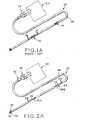
Figures 1A and1B , a prior art pacing lead is shown for use in medical applications. Implantable cardio defibrillator (ICD) 20 is used for sensing electrical activity in the heart and for delivering a shock if heart activity slows or stops. ICD 20 is implantable and has flexible, elongated conductive lead 26 (Figure 1B ) withelectrical connector 22 extending from one and thereof to plug intocontrol 24 for controlling ICD 20 and for providing the electrical supply.Control 24 is implanted just beneath the skin, often in the chest or abdomen. Lead 26 is constructed from two or three electricallyconductive wires 27 such as wires having an alloy exterior tube filled with highly conductive silver, for example. Eachwire 27 is substantially covered withinsulating material 29.Lead 26 is then substantially covered withinsulating material 28. At two locations alonglead 26,coils 30 are located which are made from a biocompatible material such as platinum, tantalum filled platinum, tantalum filled platinum-iridium, or the like.Coils 30 are secured toindividual wires 27 oflead 26 by any suitable process including laser welding. The portion ofwire 27 in contact withcoil 30 has insulatingmaterial 29 removed to allow for the welding process. Thesecoils 30 form the contacts which engage the heart tissue at specific locations to deliver as electrical voltage, whencontrol 24 senses the need to deliver such voltage.- The interface between
insulating material 28 andcoils 30 must be hermetically sealed to prevent fluids from contactingwires 27 oflead 26 and causing corrosion and possible eventual failure of the ICD. Problems exist in that the achieving a hermetic seal of a polymeric material and a metal is difficult and costly. The bond may be susceptible to corrosion and bodily fluid leaking into the area betweencoil 30 orinsulating materials 28, andwires 27 oflead 26. In addition, the materials used to formcoils 30 are very flexible and may be easily damaged simply from handling the coils. The welding process betweenwires 27 oflead 26 andcoils 30 is a further step in the manufacturing process which increases the cost of production of ICD 20. - In the medical device industry, leads are used to transmit an electrical voltage from an electrical supply source to an area in a human body. The lead interfaces with tissues in the body so that an electrical signal may be introduced to a particular area of the body. Such leads may be implanted in a patient at any location in the body where the electrophysiology needs to be monitored and/or artificially altered. Specific applications may be implantable defibrillators or pacing leads. The leads may also be used for pain relief or pain suppression in the back or spine relating to diseases such as Parkinson's disease. The lead may be further implanted in the stomach to subside hunger pains. For patients with neurological damage, the leads might be used to replace the nerve and act to transmit electrical signals from one place to another in the body. These devices are most certainly used in humans however, they are not limited to humans and may be adapted for use in animals.
- The devices are designed for long term implantations and must have several properties including resistivity, corrosion resistance, radiopacity, reliability, stiffness, fatigue life, weldability, MRI compatibility, and biocompatibility. Other characteristics of the device include a predetermined ultimate tensile strength, Young's modulus, level of inclusions, fracture toughness, and percent elongation. In addition, the types of materials used, the construction, and the cost of manufacturing the device are all factors.
- It is therefore an object of the present invention to provide an implantable medical lead with both good electrical conductivity and high flexibility.
- The above object is achieved by providing an implantable medical lead made of biocompatible materials for use with an implantable medical device including a metallic wire having an outer shell made of a first metal and a plurality of wire elements disposed within said shell, each of said wire elements comprising a metallic shell made of a second metal, said metallic shell filled with a third metal, said plurality of wire elements being compacted together whereby voids are removed within said outer shell, characterized in that the voids are removed when the metallic wire is drawn to reduce the diameter of the wire to the desired size. The wire includes a plurality of strands, wires, or elements of material which are arranged in a particular orientation and are twisted or braided into a bundle before being positioned within an outer tube. The strands are formed from any of a plurality of materials to define the mechanical and electrical characteristics of the device. In addition, a hollow strand may be used to allow for fluid transfer along the length of the device for use in drug delivery to the patient, for example. Alternatively, a fiber optic strand could be included as well as electrically insulated strands. The wire may be covered with an insulating material.
- An advantage of the present invention is that by use of the present invention, the need for conductive coils in pacing leads is eliminated.
- Another advantage of the present invention is that the risk for corrosion of the wires used in pacing leads and the like is significantly reduced.
- Yet another advantage of the present invention is that by using a wire having a plurality of strands or elements within the outer tubing, the wire is more flexible and is less subject to mechanical failure due to fatigue than prior art wires.
- Yet still another advantage is a wire which is more comfortable to the patient.
- The above mentioned and other features and objects of this invention, and the manner of attaining them, will become more apparent and the invention itself will be better understood by reference to the following description of embodiments of the invention taken in conjunction with the accompanying drawings, wherein:
Figure 1A is a perspective view of a prior art implantable cardio defibrillator using materials in accordance with the prior art.Figure 1B is a sectional view ofFigure 1A taken alongline 1B-1B.Figure 2A is a perspective view of an implantable cardio defibrillator using a lead in accordance with the present invention.Figure 2B is a sectional view ofFigure 2A taken alongline 2B-2B.Figure 3 is an exploded perspective view of a plurality of twisted strands assembled within a tube.Figure 4 is a sectional view of the assembled plurality of twisted strands and outer tube ofFigure 3 .Figure 5 is a sectional view of the assembled plurality of strands and outer tubing ofFigure 4 after drawing of the assembly.Figure 6 is a sectional view of the assembled plurality of strands and outer tubing after drawing of the assembly to a smaller diameter than that shown inFigure 5 .Figure 7 is a sectional view of the assembled plurality of strands and outer tubing after drawing of the assembly to a smaller diameter than that shown inFigure 6 .Figure 8 is a sectional view of an alternative arrangement of a plurality of strands.Figure 9 is a sectional view of the alternative arrangement ofFigure 8 located in an outer tubing.Figure 10 is a sectional view of a third arrangement of a plurality of strands assembled with an outer tubing.Figure 11 is a sectional view of a fourth arrangement showing the plurality of strands assembled with an outer tubingFigure 9 located within a second outer tubing.- Corresponding reference characters indicate corresponding parts throughout the several views. Although the exemplification set out herein illustrates the invention, the embodiments disclosed below are not intended to be exhaustive or to be construed as limiting the scope of the invention to the precise forms disclosed.
- Referring to
Figure 2A , one example of a device utilizing the lead formed in accordance with the present invention is illustrated. Implantable cardio defibrillator (ICD) 32 includes an elongated lead used to shock the heart when the heart rate becomes irregular.ICD 32 hasfirst end 34 andsecond end 36.First end 34 is provided withelectrical connectors 38 which engagecontrol 40 which includes an electrical supply or battery pack.Control 40 is implanted just beneath the skin of the patient and is designed to have a long life so that frequent removal and replacement is unnecessary.Second end 36 is mounted in the area of the body being sensed which, in this example, is the heart.Second end 36 is provided withbarbs 42 which anchor the end ofICD 32 in place.Lead 43 extends the length ofICD 32 and includes threewires 44.End 46 of onewire 44 hasbarbs 42 mounted thereon and is exposed.Wire end 46 acts as a sensor to monitor the heart's activity and initiate shock treatments to the heart when necessary. - Referring to
Figures 2A and2B , lead 43 is covered with a layer of insulatingmaterial 48 which may be formed from any suitable, biocompatible material such as, for example, urethane, to electrically insulate the conductor. Insulatingmaterial 48 substantially extends the length oflead 43 with the exception ofwire end 46 andcontact sections wire 44 oflead 43 is exposed to the body tissues atend 46 and at eachcontact sections lead 43, electrical potential is created betweenend 46, andcontact sections Contact sections - Referring now to
Figures 3 and 4 ,wire 44 is constructed such that it acts as both the electrical contact surface and the electrical lead, thus makingcoils 30 ofFigure 1A unnecessary for providing the interface between the conductor and the body tissue. Thus, corrosion at the urethane to metal joint ofFigure 1B between insulatingmaterial 28 and coils 30 is eliminated. In addition, sincefragile coils 30 are also eliminated, the cost of assembly and materials is reduced. Wire 44 comprises drawn strand filled tubing wire formed fromouter tubing 52 and a plurality of strands, elements orwires 54. Each of the strands may comprise a drawn filled tube wire. The initial size of the strand diameter may be in the range of 1mm - 11mm. The plurality ofstrands 54 are twisted or braided into a braided bundle as shown inFigure 3 with the outer strands being rotated aboutcenter strand 56. The twisted plurality ofstrands 54 is positioned withinouter tubing 52 and the conductor is thereafter drawn to the desired diameter. The twisting ofstrands 54 into a braided bundle ensures thatwire 44 has the correct orientation ofstrands 54 throughout its length after being drawn. Aswire 44 is drawn,strands 54 are lengthened and align in the predetermined arrangement. The diameter of drawnouter tubing 52 may be in the range of 2-12 mm, for example, but may be smaller for certain applications.- There are several advantages to using
strands 54 insidetubing 52.Strands 54 provide a moreflexible wire 44 which is an important factor when snakingwire 44 through the patient's arteries, for example. Themore strands 54 used, the greater the flexibility. Additionally, overall fatigue life is improved forwire 44. For example, if onestrand 54 has a crack initiated at a high stress point or stress riser sostrand 54 ultimately fails, fatigue must be reinitiated in another ofstrands 54 until all ofstrands 54 fail beforewire 44 fails completely, thus improving the life ofwire 44. Wire 44 is a metal-to-metal composite that combines the desired physical and mechanical properties of two or more materials into a single lead.Wire 44 is drawn at ambient temperature. However, as the drawing process occurs, the temperature and pressures increase significantly causing the formation of mechanical bonds betweenstrands 54 andouter tubing 52. By using the drawn strand filled tube technology, dissimilar materials may be combined to provide a variety of properties in asingle conductor 54. The composite then has anouter tubing layer 52 which is biocompatible and electrically conductive while the core material is designed to provide strength, conductivity, radiopacity, resiliency, MRI enhancement, or the like.- In the embodiments shown in the figures,
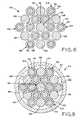
wire 44 is provided with 19strands 54. The number ofstrands 54 however may be any desired number to filltubing 52, or to provide particular properties to wire 44 as will be discussed further hereinbelow. The diameter of theindividual strands 54 also determines the number of strands used to fillouter tubing 52. In addition, the number ofstrands 54 directly relates to the cost ofwire 44. Outer tubing 52 is constructed from a biocompatible material so that the necessary electrical contact is made directly betweenwire 44 and body tissues. Such materials may include platinum or platinum alloys, tantalum or tantalum alloys, tantalum filled platinum, tantalum filled platinum-iridium, or the like.Outer tubing 52 has a thickness which is dependent upon the type ofwire 44 which is desired. The thicker the wall ofouter tubing 52, the more rigidity it provides to wire 44. If the wall ofouter tubing 52 is made thinner,wire 44 is more flexible and the cost of materials is reduced. The outer tubing however, should not be made too thin so as to risk compromising the outer wall ofwire 44.- Referring to
Figure 4 , a first embodiment ofwire 44 is illustrated havingidentical strands 54. In this instance,strands 54 comprise drawn filled tubing wires.Stand 54 is a metal to metal composite comprising anouter tubing 58 formed from any suitable material possessing the characteristics desired inwire 44. One such material may be a cobalt-nickel-chromium alloy known as ASTM Standard F562. The ASTM F562 material has characteristics including strength and long fatigue life. Thestrands 54 are filled withsilver 60 because silver is ductile and malleable, and has very high electrical and thermal conductivity. One acceptable type of strand is filled with 41 percent silver by weight. However, any suitable amount of silver or other suitable conductor may be used. For example, if 60 percent silver, by weight, is used in the strands, the strands have higher electrical and thermal conductivity. However, less ASTM F562 is then used and the strength of the strand is reduced. The combination of metals is ultimately determined by the desired properties for eachstrand 64. An alternative material which may be used in place of ASTM F562 material is a similar alloy. In addition to ASTM F562 materials such as ASTM Standard F90, F538, and other nickel, cobalt based super alloys, titanium, nitinol, and tantalum materials may be used. A material which has a much longer fatigue life than ASTM F562 and which is described in U.S. Patent Application, entitled "Cobalt Nickel Chromium Molybdenum Alloy With A Reduced Level Of Titanium Nitride Inclusions," filed September 5, 2003, the disclosure of which is hereby incorporated herein by reference, may also be useful in particular applications oflead 44. - Once the
strands 54 are positioned withinouter tubing 52,wire 44 is drawn to reduce the diameter to the desired size. Referring toFigures 5, 6, and 7 ,wire 44 is illustrated in stages as it is drawn to a small diameter. As the conductor is drawn, thestrands 54 impinge upon one another andinner surface 62 ofouter tubing 52. The round shape of eachstrand 54 is compromised by being compressed intoadjacent strands 54 andinner tubing surface 62. The material used forouter tubing 52 is relatively ductile compared to ASTM F562, for example, which is whyinner tubing surface 62 becomes deformed asouter tubing 52 is compressed againststrands 54. The thickness ofouter tubing 52 further depends upon the ability of the tubing material to apply forces againststrands 54 to compress and deform the strands without compromising the outer tubing. - Referring to
Figure 7 ,center strand 56 has a substantially hexagonal cross section while the rest ofstrands 54 have non-hexagonal cross sections because they are in the transition area between the core andinner tubing surface 62. If the number ofstrands 54 is increased, the layers of strands surrounding center stand 56 would increasingly show a substantially hexagonal cross section, the hexagonal shape migrating fromcenter strand 56 toward the outer transition layers. - In order to eliminate some of the deformation of
inner tubing surface 62,outer strands 54 could be swaged to develop facets which would engagesurface 62. The interface betweenstrands 54 andinner tubing surface 62 may then be preserved due to the more uniform pressure being exerted betweenstrands 54 andouter tubing 52. This may help to reduce the risk of compromising a thinner walledouter tubing 52. - After
wire 44 has been drawn to an appropriate length or cut from a roll of drawn strand filled tubing wire, for example, insulating material 49 (Figure 2B ) is applied to the outer surface ofouter tubing 52. Insulatingmaterial 49 is applied to eachwire 44 in any suitable manner to electrically insulatewires 44 and define the three contact points with the body,sensor 46 and bothcontact sections Figure 2B , a portion of insulatingmaterial 49 is removed from wire 44' to definecontact section 50A with the other twowires 44" and 44'" remaining completely insulated atcontact section 50A. Similarly, a portion of insultingmaterial 49 is removed fromwire 44" to definecontact section 50B. Insulatingmaterial 49 is removed atcontact end 46 ofwire 44"' to provide a sensor. The thickness of insulatingmaterial 49 can be reduced since the sealing engagement between insulatingmaterial 28 and coils 30 of the prior art is eliminated. This sealing engagement is provided to prevent fluids from coming into contact withconductor 20 of the prior art. By completely encasing the inner, electrically conductive portion orstrands 54 with a biocompatibleouter tubing 52, the risk of contact of fluids withstrands 54 is substantially eliminated. Thinner coatings of insulatingmaterial 49 makeswires 44 and thus lead 43 more pliable, allowing for easier insertion into a patient. - In addition, the manufacturing of
wire 44 may be simplified by the elimination ofcoils 30. Insulatingmaterial 49 is simply removed fromwire 44 atsensor 46 andcontact sections wire 44. Alternatively, sleeves of insultingmaterial 49 may be positioned about the outer surface ofouter tubing 52 and drawn down withwire 44. - When constructing
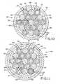
lead 43, insulatingmaterial 48 is then applied to the bundle of threewires 44', 44", and 44"', by any suitable method so as to insulate and containwires 44 while exposing the electricalcontact areas sensor 46, andcontact sections material 48 also maintain the orientation of the wires, keeping the exposed portions ofwires 44 aligned with the openings definingcontact sections material 48. Strands 54 located inouter tubing 52 may include various types of materials to provide specific mechanical attributes to wire 44. Referring to the embodiment shown inFigures 8 and 9 , several ofstrands 54 arestrands 64 as in the previous embodiment. Theinner silver 60 ofstrands 64 provides electrical conductivity throughwire 44 whileouter tubing 58 adds strength. To further strengthenwire 44 and improve fatigue life,solid strands 66 of materials including ASTM F562, and the like may be included in the plurality ofstrands 54. Other properties may be specifically addressed inwire 44 by adding different types ofstrands 54. For example, by adding solid platinum ortantalum strands 68, radiopacity ofwire 44 is enhanced. Tungsten has excellent corrosion resistance and may be added to improve that particular property ofwire 44. Ultimately, any types ofstrands 54 may be combined to create a lead 44 have predetermined properties.- An alternative method of building the stiffness of
wire 44 as shown inFigure 11 would be to positionstrands 54 within a first tube of a material such as ASTM F562, for example, and then to position the ASTM F562 or strand filled tube wire in second,outer tubing 72 having the properties required ofouter tubing 52.Second tubing 72 would be of a material such as platinum, tantalum filled platinum, tantalum filled platinum-iridium, or the like, all of which are biocompatible and electrically conductive. The entire assembly could then be drawn to the desired diameter. Further, secondouter tubing 72 could be in the form of a strip which is wrapped aroundfirst tube 52 and laser welded. - Referring to
Figure 10 , a further embodiment is illustrated in which one ofstrands 54 is a tubular,hollow strand 70.Hollow strand 70 would allow for passage of fluid throughwire 44 which may be useful for applications involving drug delivery, for example. - Further,
Figure 11 also shows aDFT strand 64 which includes asilver core 64,tubing 58, and aninsulation layer 76. Additionally,Figure 11 shows astrand 64 with a glass, fiber optic,core 78 and ametallic tubing 58. If desired, thetubing 58 could be deleted fromcore 78.
Claims (17)
- An implantable medical lead (43) made of biocompatible materials for use with an implantable medical device (32) including a metallic wire (44) having an outer shell (52) made of a first metal and a plurality of wire elements (54) disposed within said shell (52), each of said wire elements (54) comprising a metallic shell (58) made of a second metal, said metallic shell (58) filled with a third metal (60), said plurality of wire elements (54) being compacted together whereby voids are removed within said outer shell (52),characterized in that the voids are removed when the metallic wire (44) is drawn to reduce the diameter of the wire (44) to the desired size.
- The lead (43) according to claim 1characterized in that said first metal is platinum.
- The lead (43) according to claim 1characterized in that said third metal (60) is silver.
- The lead (43) according to claim 1characterized in that said second metal is ASTM Standard F562.
- The lead (43) according to claim 1characterized in that said wire elements (54) are twisted together into a bundle.
- The lead (43) according to claim 1characterized in that said plurality of wire elements (54) includes at least one hollow tube (70).
- The lead (43) according to claim 1characterized in that at least two of said plurality of metallic shells (58) are filled with different metals
- The lead (43) according to claim 7characterized in that one of said metallic shells (58) is filled with silver and another of said metallic shells is filled with tantalum.
- The lead (43) according to claim 1characterized by a layer of electrically insulating material (28) covering said outer shell (52).
- The lead (43) according to claim 1characterized by a second outer shell (72) covering said outer shell (52), said second outer shell made of a fourth biocompatible metal.
- A method of making an implantable lead (43) for use with an implantable medical device (32), said methodcharacterized by the steps of:providing a first tube (52) made of a first biocompatible metal, said first tube having a first diameter;forming a plurality of wire elements (54) into a bundle, said wire elements each comprising a metallic shell (58) made of a second metal, said metallic shell filled with a third metal (60);inserting said bundle into said first tube (52) to form an assembly; andthereafter drawing said assembly down to form a wire with a second diameter whereby no voids exist within said first tube (52).
- The method according to claim 11characterized in that at least two of said wire elements (54) are filled with different metals.
- The method according to claim 11characterized in that said third metal is silver.
- The method according to claim 11characterized in that said first metal is platinum.
- The method according to claim 11characterized in that said second metal is ASTM Standard F562.
- The method according to claim 11characterized by the additional step of, prior to said drawing step, providing a second metallic tube (72) made of a fourth biocompatible metal and inserting said assembly into said second metallic tube (72).
- The method according to claim 11characterized in that said method further includes the step of coating said first tube (52) with an electrically non-conductive insulating material (28).
Applications Claiming Priority (2)
| Application Number | Priority Date | Filing Date | Title |
|---|---|---|---|
| US54374004P | 2004-02-11 | 2004-02-11 | |
| PCT/US2004/029957WO2005081681A2 (en) | 2004-02-11 | 2004-09-13 | Drawn strand filled tubing wire |
Publications (3)
| Publication Number | Publication Date |
|---|---|
| EP1718361A2 EP1718361A2 (en) | 2006-11-08 |
| EP1718361A4 EP1718361A4 (en) | 2010-01-13 |
| EP1718361B1true EP1718361B1 (en) | 2015-06-17 |
Family
ID=34910708
Family Applications (1)
| Application Number | Title | Priority Date | Filing Date |
|---|---|---|---|
| EP04783973.3AExpired - LifetimeEP1718361B1 (en) | 2004-02-11 | 2004-09-13 | Drawn strand filled tubing wire |
Country Status (4)
| Country | Link |
|---|---|
| US (2) | US7501579B2 (en) |
| EP (1) | EP1718361B1 (en) |
| JP (1) | JP4452724B2 (en) |
| WO (1) | WO2005081681A2 (en) |
Cited By (2)
| Publication number | Priority date | Publication date | Assignee | Title |
|---|---|---|---|---|
| US11266828B2 (en) | 2018-12-06 | 2022-03-08 | Medtronic, Inc. | Implantable medical lead with moveable conductors |
| US11357993B2 (en) | 2018-12-06 | 2022-06-14 | Medtronic, Inc. | Implantable medical lead with moveable conductors |
Families Citing this family (77)
| Publication number | Priority date | Publication date | Assignee | Title |
|---|---|---|---|---|
| EP1718361B1 (en)* | 2004-02-11 | 2015-06-17 | Fort Wayne Metals Research Products Corporation | Drawn strand filled tubing wire |
| US7511245B2 (en)* | 2005-09-12 | 2009-03-31 | Nelson Stud Welding, Inc. | Stud welding apparatus with composite cable |
| EP1935449B1 (en)* | 2006-12-19 | 2011-10-19 | Greatbatch Ltd. | Braided electrical lead |
| US20110022149A1 (en) | 2007-06-04 | 2011-01-27 | Cox Brian J | Methods and devices for treatment of vascular defects |
| GB2457737A (en)* | 2008-02-25 | 2009-08-26 | Survitec Group Ltd | Portable flexible compression chamber |
| EP2254656A1 (en)* | 2008-02-29 | 2010-12-01 | Fort Wayne Metals Research Products Corporation | Alternating core composite wire |
| AU2009242528B2 (en) | 2008-05-02 | 2015-12-10 | Microvention, Inc. | Filamentary devices for treatment of vascular defects |
| US20100012347A1 (en)* | 2008-07-16 | 2010-01-21 | Greatbatch Ltd. | Blended coiled cable |
| US8364281B2 (en)* | 2008-11-07 | 2013-01-29 | W. L. Gore & Associates, Inc. | Implantable lead |
| US8996134B2 (en) | 2008-11-07 | 2015-03-31 | W. L. Gore & Associates, Inc. | Implantable lead |
| EP2194278A1 (en) | 2008-12-05 | 2010-06-09 | ECP Entwicklungsgesellschaft mbH | Fluid pump with a rotor |
| US8404976B2 (en) | 2009-01-30 | 2013-03-26 | Fort Wayne Metals Research Products Corporation | Fused wires |
| EP2216059A1 (en) | 2009-02-04 | 2010-08-11 | ECP Entwicklungsgesellschaft mbH | Catheter device with a catheter and an actuation device |
| DE102009009557A1 (en)* | 2009-02-19 | 2010-09-02 | W.C. Heraeus Gmbh | Electrically conductive materials, leads and cables for stimulation electrodes |
| EP2229965A1 (en) | 2009-03-18 | 2010-09-22 | ECP Entwicklungsgesellschaft mbH | Fluid pump with particular form of a rotor blade |
| US8639352B2 (en)* | 2009-04-06 | 2014-01-28 | Medtronic, Inc. | Wire configuration and method of making for an implantable medical apparatus |
| EP2246078A1 (en) | 2009-04-29 | 2010-11-03 | ECP Entwicklungsgesellschaft mbH | Shaft assembly with a shaft which moves within a fluid-filled casing |
| EP2248544A1 (en) | 2009-05-05 | 2010-11-10 | ECP Entwicklungsgesellschaft mbH | Fluid pump with variable circumference, particularly for medical use |
| EP2266640A1 (en) | 2009-06-25 | 2010-12-29 | ECP Entwicklungsgesellschaft mbH | Compressible and expandable turbine blade for a fluid pump |
| RU2540530C2 (en)* | 2009-07-24 | 2015-02-10 | Сапиенс Стиринг Брейн Стимьюлейшн Б.В. | Medical device for electric stimulation |
| US8100881B2 (en) | 2009-08-04 | 2012-01-24 | Cook Medical Technologies Llc | Flexible medical device for clot removal from small vessels |
| EP2282070B1 (en) | 2009-08-06 | 2012-10-17 | ECP Entwicklungsgesellschaft mbH | Catheter device with a coupling device for a drive device |
| EP2298372A1 (en) | 2009-09-22 | 2011-03-23 | ECP Entwicklungsgesellschaft mbH | Rotor for an axial pump for transporting a fluid |
| EP2298371A1 (en) | 2009-09-22 | 2011-03-23 | ECP Entwicklungsgesellschaft mbH | Function element, in particular fluid pump with a housing and a transport element |
| EP2299119B1 (en) | 2009-09-22 | 2018-11-07 | ECP Entwicklungsgesellschaft mbH | Inflatable rotor for a fluid pump |
| EP2314331B1 (en) | 2009-10-23 | 2013-12-11 | ECP Entwicklungsgesellschaft mbH | Catheter pump arrangement and flexible shaft arrangement with a cable core |
| EP2314330A1 (en) | 2009-10-23 | 2011-04-27 | ECP Entwicklungsgesellschaft mbH | Flexible shaft arrangement |
| JP5421064B2 (en)* | 2009-10-26 | 2014-02-19 | 後藤電子 株式会社 | High frequency high voltage high current wire |
| EP2338541A1 (en) | 2009-12-23 | 2011-06-29 | ECP Entwicklungsgesellschaft mbH | Radial compressible and expandable rotor for a fluid pump |
| EP2338539A1 (en) | 2009-12-23 | 2011-06-29 | ECP Entwicklungsgesellschaft mbH | Pump device with a detection device |
| EP2338540A1 (en) | 2009-12-23 | 2011-06-29 | ECP Entwicklungsgesellschaft mbH | Delivery blade for a compressible rotor |
| EP2347778A1 (en) | 2010-01-25 | 2011-07-27 | ECP Entwicklungsgesellschaft mbH | Fluid pump with a radially compressible rotor |
| EP2363157A1 (en) | 2010-03-05 | 2011-09-07 | ECP Entwicklungsgesellschaft mbH | Device for exerting mechanical force on a medium, in particular fluid pump |
| EP2388029A1 (en) | 2010-05-17 | 2011-11-23 | ECP Entwicklungsgesellschaft mbH | Pump array |
| EP2585125B1 (en) | 2010-06-25 | 2014-11-19 | Fort Wayne Metals Research Products Corporation | Biodegradable composite wire for medical devices |
| EP2399639A1 (en) | 2010-06-25 | 2011-12-28 | ECP Entwicklungsgesellschaft mbH | System for introducing a pump |
| EP2407185A1 (en) | 2010-07-15 | 2012-01-18 | ECP Entwicklungsgesellschaft mbH | Radial compressible and expandable rotor for a pump with a turbine blade |
| EP2407187A3 (en) | 2010-07-15 | 2012-06-20 | ECP Entwicklungsgesellschaft mbH | Blood pump for invasive application within the body of a patient |
| EP2407186A1 (en) | 2010-07-15 | 2012-01-18 | ECP Entwicklungsgesellschaft mbH | Rotor for a pump, produced with an initial elastic material |
| EP2422735A1 (en) | 2010-08-27 | 2012-02-29 | ECP Entwicklungsgesellschaft mbH | Implantable blood transportation device, manipulation device and coupling device |
| CN101927057B (en)* | 2010-08-31 | 2013-07-03 | 清华大学 | Pacemaker and pacemaker electrode |
| EP2497521A1 (en) | 2011-03-10 | 2012-09-12 | ECP Entwicklungsgesellschaft mbH | Push device for axial insertion of a string-shaped, flexible body |
| US8660662B2 (en) | 2011-04-22 | 2014-02-25 | Medtronic, Inc. | Low impedance, low modulus wire configurations for a medical device |
| US9409008B2 (en) | 2011-04-22 | 2016-08-09 | Medtronic, Inc. | Cable configurations for a medical device |
| EP2564771A1 (en) | 2011-09-05 | 2013-03-06 | ECP Entwicklungsgesellschaft mbH | Medicinal product with a functional element for invasive use in the body of a patient |
| US8926492B2 (en) | 2011-10-11 | 2015-01-06 | Ecp Entwicklungsgesellschaft Mbh | Housing for a functional element |
| EP2581107A1 (en)* | 2011-10-14 | 2013-04-17 | Sorin CRM SAS | Detection/stimulation microprobe implantable in venous, arterial or lymphatic networks |
| US20140187972A1 (en)* | 2012-12-31 | 2014-07-03 | Volcano Corporation | Guidewire Devices and Methods |
| FR3006594A1 (en)* | 2013-06-11 | 2014-12-12 | Sorin Crm Sas | IMPLANTABLE MICROSONDE FOR DETECTION / STIMULATION INCORPORATING AN ANTI-INFLAMMATORY AGENT |
| US9955976B2 (en) | 2013-08-16 | 2018-05-01 | Sequent Medical, Inc. | Filamentary devices for treatment of vascular defects |
| US9078658B2 (en) | 2013-08-16 | 2015-07-14 | Sequent Medical, Inc. | Filamentary devices for treatment of vascular defects |
| US9140438B2 (en) | 2013-09-13 | 2015-09-22 | Willis Electric Co., Ltd. | Decorative lighting with reinforced wiring |
| US9157588B2 (en) | 2013-09-13 | 2015-10-13 | Willis Electric Co., Ltd | Decorative lighting with reinforced wiring |
| US20150127080A1 (en)* | 2013-11-01 | 2015-05-07 | Composite Materials Technology, Inc. | Medical implantable lead and manufacture thereof |
| US9629635B2 (en) | 2014-04-14 | 2017-04-25 | Sequent Medical, Inc. | Devices for therapeutic vascular procedures |
| US9498316B1 (en) | 2014-07-10 | 2016-11-22 | Composite Materials Technology, Inc. | Biocompatible extremely fine tantalum filament scaffolding for bone and soft tissue prosthesis |
| US9155605B1 (en) | 2014-07-10 | 2015-10-13 | Composite Materials Technology, Inc. | Biocompatible extremely fine tantalum filament scaffolding for bone and soft tissue prosthesis |
| GB2543318A (en)* | 2015-10-14 | 2017-04-19 | Heraeus Electro Nite Int | Consumable optical fiber for measuring a temperature of a molten steel bath |
| GB2543319A (en)* | 2015-10-14 | 2017-04-19 | Heraeus Electro Nite Int | Cored wire, method and device for the production |
| CA2946387A1 (en) | 2015-10-26 | 2017-04-26 | Willis Electric Co., Ltd. | Tangle-resistant decorative lighting assembly |
| EP3496884B1 (en) | 2016-08-12 | 2021-06-16 | COMPOSITE MATERIALS TECHNOLOGY, Inc. | Electrolytic capacitor and method for improved electrolytic capacitor anodes |
| CN109562950B (en) | 2016-09-01 | 2020-05-19 | 复合材料技术公司 | Nanoscale/nanostructured Si coatings on valve metal substrates for LIB anodes |
| US12195916B2 (en) | 2017-03-31 | 2025-01-14 | Fort Wayne Metals Research Products, Llc | Small diameter cable |
| US10939990B2 (en)* | 2017-11-28 | 2021-03-09 | Medtronic Vascular, Inc. | Graft material having selectively advanced permeability structure and method |
| US11364368B2 (en)* | 2018-08-14 | 2022-06-21 | Biosense Webster (Israel) Ltd. | Guidewire with an integrated flexible tube |
| AU2019222842A1 (en) | 2018-09-10 | 2020-03-26 | Northern Development AS | Percutaneous Lead |
| EP3911246A1 (en) | 2019-01-18 | 2021-11-24 | W.L. Gore & Associates, Inc. | Bioabsorbable medical devices |
| US11559309B2 (en) | 2019-03-15 | 2023-01-24 | Sequent Medical, Inc. | Filamentary devices for treatment of vascular defects |
| CN113573650B (en) | 2019-03-15 | 2024-05-28 | 后续医疗股份有限公司 | Silk device with flexible connector for treating vascular defects |
| CN113573765B (en) | 2019-03-15 | 2024-08-13 | 美科微先股份有限公司 | Silk device for treating vascular defects |
| DE102019116590B4 (en)* | 2019-06-19 | 2021-01-07 | Iav Gmbh Ingenieurgesellschaft Auto Und Verkehr | Electrical conductor made of two metallic materials, method of manufacture and use |
| US12023034B2 (en) | 2020-03-11 | 2024-07-02 | Microvention, Inc. | Devices for treatment of vascular defects |
| US12070220B2 (en) | 2020-03-11 | 2024-08-27 | Microvention, Inc. | Devices having multiple permeable shells for treatment of vascular defects |
| US20210282789A1 (en) | 2020-03-11 | 2021-09-16 | Microvention, Inc. | Multiple layer devices for treatment of vascular defects |
| EP4395676A1 (en)* | 2021-09-01 | 2024-07-10 | Stereotaxis, Inc. | Drawn filled tubing magnets, and methods, devices, and systems related thereto |
| WO2023204036A1 (en)* | 2022-04-19 | 2023-10-26 | 住友電気工業株式会社 | Wire, stranded wire, cable, and method for producing wire |
| CR20250047A (en) | 2022-08-10 | 2025-05-30 | Fort Wayne Metals Res Products Llc | Composite wire with coating |
Citations (3)
| Publication number | Priority date | Publication date | Assignee | Title |
|---|---|---|---|---|
| US5283232A (en)* | 1987-03-20 | 1994-02-01 | Fujikura Ltd. | Method for producing oxide superconducting composite wire |
| WO2000013192A1 (en)* | 1998-08-31 | 2000-03-09 | General Science And Technology Corporation | Medical devices incorporating at least one element made from a plurality of twisted and drawn wires at least one of the wires being a nickel-titanium alloy wire |
| US6399886B1 (en)* | 1997-05-02 | 2002-06-04 | General Science & Technology Corp. | Multifilament drawn radiopaque high elastic cables and methods of making the same |
Family Cites Families (38)
| Publication number | Priority date | Publication date | Assignee | Title |
|---|---|---|---|---|
| US2050298A (en)* | 1934-04-25 | 1936-08-11 | Thos Firth & John Brown Ltd | Metal reducing method |
| FR1513586A (en)* | 1967-01-06 | 1968-02-16 | Comp Generale Electricite | High mechanical strength superconducting conductor |
| BE755631A (en)* | 1969-09-02 | 1971-03-02 | Imp Metal Ind Kynoch Ltd | IMPROVEMENTS FOR ELECTRIC CONDUCTORS |
| US3983521A (en)* | 1972-09-11 | 1976-09-28 | The Furukawa Electric Co., Ltd. | Flexible superconducting composite compound wires |
| DE2950022C2 (en)* | 1979-12-17 | 1984-01-12 | Vsesojuznyj kardiologičeskij naučnyj centr Akademii medicinskich Nauk SSSR,, Moskva | Electrical conductor for implantation in the human body |
| US4559951A (en)* | 1982-11-29 | 1985-12-24 | Cardiac Pacemakers, Inc. | Catheter assembly |
| JPS6271113A (en) | 1985-09-25 | 1987-04-01 | 株式会社東芝 | Nb↓3Sn compound superconducting wire |
| US4646428A (en)* | 1985-11-21 | 1987-03-03 | Oxford Superconducting Technology | Method of fabricating multifilament intermetallic superconductor |
| US4863804A (en)* | 1985-11-29 | 1989-09-05 | Westinghouse Electric Corporation | Superconductor wire and methods of constructing same |
| US4989617A (en)* | 1989-07-14 | 1991-02-05 | Case Western Reserve University | Intramuscular electrode for neuromuscular stimulation system |
| US5203348A (en)* | 1990-06-06 | 1993-04-20 | Cardiac Pacemakers, Inc. | Subcutaneous defibrillation electrodes |
| US5224491A (en)* | 1991-01-07 | 1993-07-06 | Medtronic, Inc. | Implantable electrode for location within a blood vessel |
| US5170802A (en)* | 1991-01-07 | 1992-12-15 | Medtronic, Inc. | Implantable electrode for location within a blood vessel |
| US5330521A (en)* | 1992-06-29 | 1994-07-19 | Cohen Donald M | Low resistance implantable electrical leads |
| US5324328A (en)* | 1992-08-05 | 1994-06-28 | Siemens Pacesetter, Inc. | Conductor for a defibrillator patch lead |
| JPH06111636A (en)* | 1992-09-30 | 1994-04-22 | Showa Electric Wire & Cable Co Ltd | Movable compound cable |
| US5630840A (en)* | 1993-01-19 | 1997-05-20 | Schneider (Usa) Inc | Clad composite stent |
| US5483022A (en)* | 1994-04-12 | 1996-01-09 | Ventritex, Inc. | Implantable conductor coil formed from cabled composite wire |
| US5716391A (en)* | 1995-08-23 | 1998-02-10 | Medtronic, Inc. | Medical electrical lead having temporarily rigid fixation |
| US5755760A (en) | 1996-03-11 | 1998-05-26 | Medtronic, Inc. | Deflectable catheter |
| US5760341A (en)* | 1996-09-10 | 1998-06-02 | Medtronic, Inc. | Conductor cable for biomedical lead |
| SE9603318D0 (en)* | 1996-09-12 | 1996-09-12 | Pacesetter Ab | Electrode cable for electrical stimulation |
| EP0971767A2 (en)* | 1996-12-19 | 2000-01-19 | Medtronic, Inc. | Medical electrical lead |
| US5796044A (en) | 1997-02-10 | 1998-08-18 | Medtronic, Inc. | Coiled wire conductor insulation for biomedical lead |
| US6307156B1 (en)* | 1997-05-02 | 2001-10-23 | General Science And Technology Corp. | High flexibility and heat dissipating coaxial cable |
| US5871531A (en) | 1997-09-25 | 1999-02-16 | Medtronic, Inc. | Medical electrical lead having tapered spiral fixation |
| US6159165A (en)* | 1997-12-05 | 2000-12-12 | Micrus Corporation | Three dimensional spherical micro-coils manufactured from radiopaque nickel-titanium microstrand |
| US6241691B1 (en)* | 1997-12-05 | 2001-06-05 | Micrus Corporation | Coated superelastic stent |
| US6168570B1 (en)* | 1997-12-05 | 2001-01-02 | Micrus Corporation | Micro-strand cable with enhanced radiopacity |
| JP2000225643A (en) | 1999-02-08 | 2000-08-15 | Honda Motor Co Ltd | Mold structure for vacuum forming apparatus and method for manufacturing the mold |
| US6516230B2 (en)* | 2000-04-26 | 2003-02-04 | Medtronic, Inc. | Medical electrical lead with fiber core |
| US6786924B2 (en)* | 2001-03-15 | 2004-09-07 | Medtronic, Inc. | Annuloplasty band and method |
| US20030032997A1 (en)* | 2001-08-10 | 2003-02-13 | Pianca Anne M. | Low impedance high strength medical electrical lead |
| US7065411B2 (en)* | 2003-04-23 | 2006-06-20 | Medtronic, Inc. | Electrical medical leads employing conductive aerogel |
| US7138582B2 (en)* | 2003-06-24 | 2006-11-21 | Medtronic, Inc. | Medical electrical lead conductor formed from modified MP35N alloy |
| US7280875B1 (en)* | 2004-02-04 | 2007-10-09 | Pacesetter, Inc. | High strength, low resistivity electrode |
| EP1718361B1 (en)* | 2004-02-11 | 2015-06-17 | Fort Wayne Metals Research Products Corporation | Drawn strand filled tubing wire |
| US7420124B2 (en)* | 2004-02-11 | 2008-09-02 | Fort Wayne Metals Research Products Corp. | Drawn strand filled tubing wire |
- 2004
- 2004-09-13EPEP04783973.3Apatent/EP1718361B1/ennot_activeExpired - Lifetime
- 2004-09-13WOPCT/US2004/029957patent/WO2005081681A2/ennot_activeApplication Discontinuation
- 2004-09-13JPJP2006553111Apatent/JP4452724B2/ennot_activeExpired - Lifetime
- 2005
- 2005-08-15USUS11/203,986patent/US7501579B2/ennot_activeExpired - Lifetime
- 2009
- 2009-01-29USUS12/361,759patent/US7745732B2/ennot_activeExpired - Lifetime
Patent Citations (3)
| Publication number | Priority date | Publication date | Assignee | Title |
|---|---|---|---|---|
| US5283232A (en)* | 1987-03-20 | 1994-02-01 | Fujikura Ltd. | Method for producing oxide superconducting composite wire |
| US6399886B1 (en)* | 1997-05-02 | 2002-06-04 | General Science & Technology Corp. | Multifilament drawn radiopaque high elastic cables and methods of making the same |
| WO2000013192A1 (en)* | 1998-08-31 | 2000-03-09 | General Science And Technology Corporation | Medical devices incorporating at least one element made from a plurality of twisted and drawn wires at least one of the wires being a nickel-titanium alloy wire |
Cited By (2)
| Publication number | Priority date | Publication date | Assignee | Title |
|---|---|---|---|---|
| US11266828B2 (en) | 2018-12-06 | 2022-03-08 | Medtronic, Inc. | Implantable medical lead with moveable conductors |
| US11357993B2 (en) | 2018-12-06 | 2022-06-14 | Medtronic, Inc. | Implantable medical lead with moveable conductors |
Also Published As
| Publication number | Publication date |
|---|---|
| US7501579B2 (en) | 2009-03-10 |
| WO2005081681A2 (en) | 2005-09-09 |
| EP1718361A4 (en) | 2010-01-13 |
| JP2007521912A (en) | 2007-08-09 |
| US7745732B2 (en) | 2010-06-29 |
| JP4452724B2 (en) | 2010-04-21 |
| EP1718361A2 (en) | 2006-11-08 |
| US20060106444A1 (en) | 2006-05-18 |
| US20090133899A1 (en) | 2009-05-28 |
| WO2005081681A3 (en) | 2006-07-27 |
Similar Documents
| Publication | Publication Date | Title |
|---|---|---|
| EP1718361B1 (en) | Drawn strand filled tubing wire | |
| US7420124B2 (en) | Drawn strand filled tubing wire | |
| US7818070B2 (en) | Method of manufacturing an implantable lead | |
| EP1594564B1 (en) | Reverse wound electrodes | |
| US8000802B2 (en) | Implantable lead with coplanar contact coupling | |
| US5522872A (en) | Electrode-conductor sleeve joint for cardiac lead | |
| US6321102B1 (en) | Cardiac lead with minimized inside diameter of sleeve | |
| US7184840B2 (en) | Implantable lead with isolated contact coupling | |
| US5324321A (en) | Medical electrical lead having sigmoidal conductors and non-circular lumens | |
| US6026567A (en) | Medical lead with stranded conductors | |
| US7930038B2 (en) | Tubular lead electrodes and methods | |
| US20110220408A1 (en) | Electrode and connector attachments for a cylindrical glass fiber wire lead | |
| EP0586099A1 (en) | Defibrillator patch lead with implantable electrically conductive elements | |
| US7486994B2 (en) | Method and device for supporting or strengthening a portion of a lead | |
| US7206642B2 (en) | Implantable lead with improved stylet lumen | |
| US20130018445A1 (en) | Neurostimulation lead | |
| EP1496985B1 (en) | Implantable lead with improved distal tip | |
| US20090259282A1 (en) | Extendable imlpantable elongated member | |
| WO2003089052A1 (en) | Stylet for an implantable lead |
Legal Events
| Date | Code | Title | Description |
|---|---|---|---|
| PUAI | Public reference made under article 153(3) epc to a published international application that has entered the european phase | Free format text:ORIGINAL CODE: 0009012 | |
| 17P | Request for examination filed | Effective date:20060812 | |
| AK | Designated contracting states | Kind code of ref document:A2 Designated state(s):AT BE BG CH CY CZ DE DK EE ES FI FR GB GR HU IE IT LI LU MC NL PL PT RO SE SI SK TR | |
| AX | Request for extension of the european patent | Extension state:AL HR LT LV MK | |
| DAX | Request for extension of the european patent (deleted) | ||
| A4 | Supplementary search report drawn up and despatched | Effective date:20091214 | |
| 17Q | First examination report despatched | Effective date:20100329 | |
| GRAP | Despatch of communication of intention to grant a patent | Free format text:ORIGINAL CODE: EPIDOSNIGR1 | |
| INTG | Intention to grant announced | Effective date:20150130 | |
| GRAS | Grant fee paid | Free format text:ORIGINAL CODE: EPIDOSNIGR3 | |
| GRAA | (expected) grant | Free format text:ORIGINAL CODE: 0009210 | |
| AK | Designated contracting states | Kind code of ref document:B1 Designated state(s):AT BE BG CH CY CZ DE DK EE ES FI FR GB GR HU IE IT LI LU MC NL PL PT RO SE SI SK TR | |
| REG | Reference to a national code | Ref country code:GB Ref legal event code:FG4D | |
| REG | Reference to a national code | Ref country code:CH Ref legal event code:EP | |
| REG | Reference to a national code | Ref country code:AT Ref legal event code:REF Ref document number:731561 Country of ref document:AT Kind code of ref document:T Effective date:20150715 | |
| REG | Reference to a national code | Ref country code:IE Ref legal event code:FG4D | |
| REG | Reference to a national code | Ref country code:DE Ref legal event code:R096 Ref document number:602004047370 Country of ref document:DE | |
| PG25 | Lapsed in a contracting state [announced via postgrant information from national office to epo] | Ref country code:FI Free format text:LAPSE BECAUSE OF FAILURE TO SUBMIT A TRANSLATION OF THE DESCRIPTION OR TO PAY THE FEE WITHIN THE PRESCRIBED TIME-LIMIT Effective date:20150617 | |
| REG | Reference to a national code | Ref country code:AT Ref legal event code:MK05 Ref document number:731561 Country of ref document:AT Kind code of ref document:T Effective date:20150617 | |
| REG | Reference to a national code | Ref country code:NL Ref legal event code:MP Effective date:20150617 | |
| PG25 | Lapsed in a contracting state [announced via postgrant information from national office to epo] | Ref country code:BG Free format text:LAPSE BECAUSE OF FAILURE TO SUBMIT A TRANSLATION OF THE DESCRIPTION OR TO PAY THE FEE WITHIN THE PRESCRIBED TIME-LIMIT Effective date:20150917 Ref country code:GR Free format text:LAPSE BECAUSE OF FAILURE TO SUBMIT A TRANSLATION OF THE DESCRIPTION OR TO PAY THE FEE WITHIN THE PRESCRIBED TIME-LIMIT Effective date:20150918 | |
| PG25 | Lapsed in a contracting state [announced via postgrant information from national office to epo] | Ref country code:EE Free format text:LAPSE BECAUSE OF FAILURE TO SUBMIT A TRANSLATION OF THE DESCRIPTION OR TO PAY THE FEE WITHIN THE PRESCRIBED TIME-LIMIT Effective date:20150617 | |
| PG25 | Lapsed in a contracting state [announced via postgrant information from national office to epo] | Ref country code:AT Free format text:LAPSE BECAUSE OF FAILURE TO SUBMIT A TRANSLATION OF THE DESCRIPTION OR TO PAY THE FEE WITHIN THE PRESCRIBED TIME-LIMIT Effective date:20150617 Ref country code:RO Free format text:LAPSE BECAUSE OF NON-PAYMENT OF DUE FEES Effective date:20150617 Ref country code:PT Free format text:LAPSE BECAUSE OF FAILURE TO SUBMIT A TRANSLATION OF THE DESCRIPTION OR TO PAY THE FEE WITHIN THE PRESCRIBED TIME-LIMIT Effective date:20151019 Ref country code:ES Free format text:LAPSE BECAUSE OF FAILURE TO SUBMIT A TRANSLATION OF THE DESCRIPTION OR TO PAY THE FEE WITHIN THE PRESCRIBED TIME-LIMIT Effective date:20150617 Ref country code:PL Free format text:LAPSE BECAUSE OF FAILURE TO SUBMIT A TRANSLATION OF THE DESCRIPTION OR TO PAY THE FEE WITHIN THE PRESCRIBED TIME-LIMIT Effective date:20150617 Ref country code:CZ Free format text:LAPSE BECAUSE OF FAILURE TO SUBMIT A TRANSLATION OF THE DESCRIPTION OR TO PAY THE FEE WITHIN THE PRESCRIBED TIME-LIMIT Effective date:20150617 Ref country code:SK Free format text:LAPSE BECAUSE OF FAILURE TO SUBMIT A TRANSLATION OF THE DESCRIPTION OR TO PAY THE FEE WITHIN THE PRESCRIBED TIME-LIMIT Effective date:20150617 | |
| REG | Reference to a national code | Ref country code:DE Ref legal event code:R097 Ref document number:602004047370 Country of ref document:DE | |
| PLBE | No opposition filed within time limit | Free format text:ORIGINAL CODE: 0009261 | |
| STAA | Information on the status of an ep patent application or granted ep patent | Free format text:STATUS: NO OPPOSITION FILED WITHIN TIME LIMIT | |
| PG25 | Lapsed in a contracting state [announced via postgrant information from national office to epo] | Ref country code:DK Free format text:LAPSE BECAUSE OF FAILURE TO SUBMIT A TRANSLATION OF THE DESCRIPTION OR TO PAY THE FEE WITHIN THE PRESCRIBED TIME-LIMIT Effective date:20150617 Ref country code:LU Free format text:LAPSE BECAUSE OF FAILURE TO SUBMIT A TRANSLATION OF THE DESCRIPTION OR TO PAY THE FEE WITHIN THE PRESCRIBED TIME-LIMIT Effective date:20150913 Ref country code:IT Free format text:LAPSE BECAUSE OF FAILURE TO SUBMIT A TRANSLATION OF THE DESCRIPTION OR TO PAY THE FEE WITHIN THE PRESCRIBED TIME-LIMIT Effective date:20150617 Ref country code:MC Free format text:LAPSE BECAUSE OF FAILURE TO SUBMIT A TRANSLATION OF THE DESCRIPTION OR TO PAY THE FEE WITHIN THE PRESCRIBED TIME-LIMIT Effective date:20150617 | |
| REG | Reference to a national code | Ref country code:CH Ref legal event code:PL | |
| 26N | No opposition filed | Effective date:20160318 | |
| PG25 | Lapsed in a contracting state [announced via postgrant information from national office to epo] | Ref country code:CH Free format text:LAPSE BECAUSE OF NON-PAYMENT OF DUE FEES Effective date:20150930 Ref country code:LI Free format text:LAPSE BECAUSE OF NON-PAYMENT OF DUE FEES Effective date:20150930 | |
| REG | Reference to a national code | Ref country code:FR Ref legal event code:PLFP Year of fee payment:13 | |
| PG25 | Lapsed in a contracting state [announced via postgrant information from national office to epo] | Ref country code:SI Free format text:LAPSE BECAUSE OF FAILURE TO SUBMIT A TRANSLATION OF THE DESCRIPTION OR TO PAY THE FEE WITHIN THE PRESCRIBED TIME-LIMIT Effective date:20150617 | |
| PG25 | Lapsed in a contracting state [announced via postgrant information from national office to epo] | Ref country code:BE Free format text:LAPSE BECAUSE OF FAILURE TO SUBMIT A TRANSLATION OF THE DESCRIPTION OR TO PAY THE FEE WITHIN THE PRESCRIBED TIME-LIMIT Effective date:20150617 | |
| PG25 | Lapsed in a contracting state [announced via postgrant information from national office to epo] | Ref country code:HU Free format text:LAPSE BECAUSE OF FAILURE TO SUBMIT A TRANSLATION OF THE DESCRIPTION OR TO PAY THE FEE WITHIN THE PRESCRIBED TIME-LIMIT; INVALID AB INITIO Effective date:20040913 | |
| PG25 | Lapsed in a contracting state [announced via postgrant information from national office to epo] | Ref country code:NL Free format text:LAPSE BECAUSE OF FAILURE TO SUBMIT A TRANSLATION OF THE DESCRIPTION OR TO PAY THE FEE WITHIN THE PRESCRIBED TIME-LIMIT Effective date:20150617 Ref country code:CY Free format text:LAPSE BECAUSE OF FAILURE TO SUBMIT A TRANSLATION OF THE DESCRIPTION OR TO PAY THE FEE WITHIN THE PRESCRIBED TIME-LIMIT Effective date:20150617 Ref country code:SE Free format text:LAPSE BECAUSE OF FAILURE TO SUBMIT A TRANSLATION OF THE DESCRIPTION OR TO PAY THE FEE WITHIN THE PRESCRIBED TIME-LIMIT Effective date:20150617 | |
| REG | Reference to a national code | Ref country code:FR Ref legal event code:PLFP Year of fee payment:14 | |
| PG25 | Lapsed in a contracting state [announced via postgrant information from national office to epo] | Ref country code:TR Free format text:LAPSE BECAUSE OF FAILURE TO SUBMIT A TRANSLATION OF THE DESCRIPTION OR TO PAY THE FEE WITHIN THE PRESCRIBED TIME-LIMIT Effective date:20150617 | |
| REG | Reference to a national code | Ref country code:FR Ref legal event code:PLFP Year of fee payment:15 | |
| P01 | Opt-out of the competence of the unified patent court (upc) registered | Effective date:20230428 | |
| PGFP | Annual fee paid to national office [announced via postgrant information from national office to epo] | Ref country code:IE Payment date:20230809 Year of fee payment:20 Ref country code:GB Payment date:20230810 Year of fee payment:20 | |
| PGFP | Annual fee paid to national office [announced via postgrant information from national office to epo] | Ref country code:FR Payment date:20230808 Year of fee payment:20 Ref country code:DE Payment date:20230808 Year of fee payment:20 | |
| REG | Reference to a national code | Ref country code:DE Ref legal event code:R081 Ref document number:602004047370 Country of ref document:DE Owner name:FORT WAYNE METALS RESEARCH PRODUCTS, LLC, FORT, US Free format text:FORMER OWNER: FORT WAYNE METALS RESEARCH PRODUCTS CORP., FORT WAYNE, IND., US | |
| REG | Reference to a national code | Ref country code:DE Ref legal event code:R071 Ref document number:602004047370 Country of ref document:DE | |
| REG | Reference to a national code | Ref country code:GB Ref legal event code:PE20 Expiry date:20240912 | |
| PG25 | Lapsed in a contracting state [announced via postgrant information from national office to epo] | Ref country code:GB Free format text:LAPSE BECAUSE OF EXPIRATION OF PROTECTION Effective date:20240912 | |
| REG | Reference to a national code | Ref country code:IE Ref legal event code:MK9A | |
| PG25 | Lapsed in a contracting state [announced via postgrant information from national office to epo] | Ref country code:GB Free format text:LAPSE BECAUSE OF EXPIRATION OF PROTECTION Effective date:20240912 | |
| PG25 | Lapsed in a contracting state [announced via postgrant information from national office to epo] | Ref country code:IE Free format text:LAPSE BECAUSE OF EXPIRATION OF PROTECTION Effective date:20240913 | |
| PG25 | Lapsed in a contracting state [announced via postgrant information from national office to epo] | Ref country code:IE Free format text:LAPSE BECAUSE OF EXPIRATION OF PROTECTION Effective date:20240913 |