EP1715903B1 - Injection device - Google Patents
Injection deviceDownload PDFInfo
- Publication number
- EP1715903B1 EP1715903B1EP05701985AEP05701985AEP1715903B1EP 1715903 B1EP1715903 B1EP 1715903B1EP 05701985 AEP05701985 AEP 05701985AEP 05701985 AEP05701985 AEP 05701985AEP 1715903 B1EP1715903 B1EP 1715903B1
- Authority
- EP
- European Patent Office
- Prior art keywords
- barrel
- needle
- injection device
- housing
- plunger
- Prior art date
- Legal status (The legal status is an assumption and is not a legal conclusion. Google has not performed a legal analysis and makes no representation as to the accuracy of the status listed.)
- Expired - Lifetime
Links
- 238000002347injectionMethods0.000titleclaimsabstractdescription126
- 239000007924injectionSubstances0.000titleclaimsabstractdescription126
- 239000003814drugSubstances0.000claimsabstractdescription32
- 238000004891communicationMethods0.000claimsabstractdescription26
- 230000033001locomotionEffects0.000claimsdescription24
- 230000000977initiatory effectEffects0.000claimsdescription5
- 230000001681protective effectEffects0.000claimsdescription4
- 101100328887Caenorhabditis elegans col-34 geneProteins0.000description22
- 239000004677NylonSubstances0.000description10
- 229920001778nylonPolymers0.000description10
- 239000007788liquidSubstances0.000description9
- 238000010068moulding (rubber)Methods0.000description8
- 230000004913activationEffects0.000description3
- 230000008901benefitEffects0.000description3
- 230000000994depressogenic effectEffects0.000description3
- 229940079593drugDrugs0.000description3
- 230000006870functionEffects0.000description3
- 230000003993interactionEffects0.000description3
- 230000000717retained effectEffects0.000description3
- 125000006850spacer groupChemical group0.000description3
- 208000012266Needlestick injuryDiseases0.000description2
- 230000006835compressionEffects0.000description2
- 238000007906compressionMethods0.000description2
- NOESYZHRGYRDHS-UHFFFAOYSA-NinsulinChemical compoundN1C(=O)C(NC(=O)C(CCC(N)=O)NC(=O)C(CCC(O)=O)NC(=O)C(C(C)C)NC(=O)C(NC(=O)CN)C(C)CC)CSSCC(C(NC(CO)C(=O)NC(CC(C)C)C(=O)NC(CC=2C=CC(O)=CC=2)C(=O)NC(CCC(N)=O)C(=O)NC(CC(C)C)C(=O)NC(CCC(O)=O)C(=O)NC(CC(N)=O)C(=O)NC(CC=2C=CC(O)=CC=2)C(=O)NC(CSSCC(NC(=O)C(C(C)C)NC(=O)C(CC(C)C)NC(=O)C(CC=2C=CC(O)=CC=2)NC(=O)C(CC(C)C)NC(=O)C(C)NC(=O)C(CCC(O)=O)NC(=O)C(C(C)C)NC(=O)C(CC(C)C)NC(=O)C(CC=2NC=NC=2)NC(=O)C(CO)NC(=O)CNC2=O)C(=O)NCC(=O)NC(CCC(O)=O)C(=O)NC(CCCNC(N)=N)C(=O)NCC(=O)NC(CC=3C=CC=CC=3)C(=O)NC(CC=3C=CC=CC=3)C(=O)NC(CC=3C=CC(O)=CC=3)C(=O)NC(C(C)O)C(=O)N3C(CCC3)C(=O)NC(CCCCN)C(=O)NC(C)C(O)=O)C(=O)NC(CC(N)=O)C(O)=O)=O)NC(=O)C(C(C)CC)NC(=O)C(CO)NC(=O)C(C(C)O)NC(=O)C1CSSCC2NC(=O)C(CC(C)C)NC(=O)C(NC(=O)C(CCC(N)=O)NC(=O)C(CC(N)=O)NC(=O)C(NC(=O)C(N)CC=1C=CC=CC=1)C(C)C)CC1=CN=CN1NOESYZHRGYRDHS-UHFFFAOYSA-N0.000description2
- 238000000465mouldingMethods0.000description2
- 230000035515penetrationEffects0.000description2
- 102000018997Growth HormoneHuman genes0.000description1
- 108010051696Growth HormoneProteins0.000description1
- 102000004877InsulinHuman genes0.000description1
- 108090001061InsulinProteins0.000description1
- 206010034912PhobiaDiseases0.000description1
- 239000000443aerosolSubstances0.000description1
- 230000000712assemblyEffects0.000description1
- 238000000429assemblyMethods0.000description1
- 230000006378damageEffects0.000description1
- 230000000694effectsEffects0.000description1
- 238000010304firingMethods0.000description1
- -1for exampleSubstances0.000description1
- 239000000122growth hormoneSubstances0.000description1
- 208000014674injuryDiseases0.000description1
- 229940125396insulinDrugs0.000description1
- 229940090046jet injectorDrugs0.000description1
- 239000000463materialSubstances0.000description1
- 238000012986modificationMethods0.000description1
- 230000004048modificationEffects0.000description1
- 230000003387muscularEffects0.000description1
- 206010033675panniculitisDiseases0.000description1
- 208000019899phobic diseaseDiseases0.000description1
- 239000004033plasticSubstances0.000description1
- 229920003023plasticPolymers0.000description1
- 230000001141propulsive effectEffects0.000description1
- 238000007920subcutaneous administrationMethods0.000description1
- 210000004304subcutaneous tissueAnatomy0.000description1
- 230000008733traumaEffects0.000description1
- 230000000007visual effectEffects0.000description1
Images


Classifications
- A—HUMAN NECESSITIES
- A61—MEDICAL OR VETERINARY SCIENCE; HYGIENE
- A61M—DEVICES FOR INTRODUCING MEDIA INTO, OR ONTO, THE BODY; DEVICES FOR TRANSDUCING BODY MEDIA OR FOR TAKING MEDIA FROM THE BODY; DEVICES FOR PRODUCING OR ENDING SLEEP OR STUPOR
- A61M5/00—Devices for bringing media into the body in a subcutaneous, intra-vascular or intramuscular way; Accessories therefor, e.g. filling or cleaning devices, arm-rests
- A61M5/178—Syringes
- A61M5/20—Automatic syringes, e.g. with automatically actuated piston rod, with automatic needle injection, filling automatically
- A61M5/2053—Media being expelled from injector by pressurised fluid or vacuum
- A—HUMAN NECESSITIES
- A61—MEDICAL OR VETERINARY SCIENCE; HYGIENE
- A61M—DEVICES FOR INTRODUCING MEDIA INTO, OR ONTO, THE BODY; DEVICES FOR TRANSDUCING BODY MEDIA OR FOR TAKING MEDIA FROM THE BODY; DEVICES FOR PRODUCING OR ENDING SLEEP OR STUPOR
- A61M5/00—Devices for bringing media into the body in a subcutaneous, intra-vascular or intramuscular way; Accessories therefor, e.g. filling or cleaning devices, arm-rests
- A61M5/178—Syringes
- A61M5/20—Automatic syringes, e.g. with automatically actuated piston rod, with automatic needle injection, filling automatically
- A—HUMAN NECESSITIES
- A61—MEDICAL OR VETERINARY SCIENCE; HYGIENE
- A61M—DEVICES FOR INTRODUCING MEDIA INTO, OR ONTO, THE BODY; DEVICES FOR TRANSDUCING BODY MEDIA OR FOR TAKING MEDIA FROM THE BODY; DEVICES FOR PRODUCING OR ENDING SLEEP OR STUPOR
- A61M5/00—Devices for bringing media into the body in a subcutaneous, intra-vascular or intramuscular way; Accessories therefor, e.g. filling or cleaning devices, arm-rests
- A61M5/178—Syringes
- A61M5/20—Automatic syringes, e.g. with automatically actuated piston rod, with automatic needle injection, filling automatically
- A61M5/2033—Spring-loaded one-shot injectors with or without automatic needle insertion
- A—HUMAN NECESSITIES
- A61—MEDICAL OR VETERINARY SCIENCE; HYGIENE
- A61M—DEVICES FOR INTRODUCING MEDIA INTO, OR ONTO, THE BODY; DEVICES FOR TRANSDUCING BODY MEDIA OR FOR TAKING MEDIA FROM THE BODY; DEVICES FOR PRODUCING OR ENDING SLEEP OR STUPOR
- A61M5/00—Devices for bringing media into the body in a subcutaneous, intra-vascular or intramuscular way; Accessories therefor, e.g. filling or cleaning devices, arm-rests
- A61M5/178—Syringes
- A61M5/31—Details
- A61M5/32—Needles; Details of needles pertaining to their connection with syringe or hub; Accessories for bringing the needle into, or holding the needle on, the body; Devices for protection of needles
- A61M5/3205—Apparatus for removing or disposing of used needles or syringes, e.g. containers; Means for protection against accidental injuries from used needles
- A61M5/321—Means for protection against accidental injuries by used needles
- A61M5/3243—Means for protection against accidental injuries by used needles being axially-extensible, e.g. protective sleeves coaxially slidable on the syringe barrel
- A61M5/326—Fully automatic sleeve extension, i.e. in which triggering of the sleeve does not require a deliberate action by the user
- A—HUMAN NECESSITIES
- A61—MEDICAL OR VETERINARY SCIENCE; HYGIENE
- A61M—DEVICES FOR INTRODUCING MEDIA INTO, OR ONTO, THE BODY; DEVICES FOR TRANSDUCING BODY MEDIA OR FOR TAKING MEDIA FROM THE BODY; DEVICES FOR PRODUCING OR ENDING SLEEP OR STUPOR
- A61M5/00—Devices for bringing media into the body in a subcutaneous, intra-vascular or intramuscular way; Accessories therefor, e.g. filling or cleaning devices, arm-rests
- A61M5/178—Syringes
- A61M5/20—Automatic syringes, e.g. with automatically actuated piston rod, with automatic needle injection, filling automatically
- A61M2005/2006—Having specific accessories
- A61M2005/2013—Having specific accessories triggering of discharging means by contact of injector with patient body
- A—HUMAN NECESSITIES
- A61—MEDICAL OR VETERINARY SCIENCE; HYGIENE
- A61M—DEVICES FOR INTRODUCING MEDIA INTO, OR ONTO, THE BODY; DEVICES FOR TRANSDUCING BODY MEDIA OR FOR TAKING MEDIA FROM THE BODY; DEVICES FOR PRODUCING OR ENDING SLEEP OR STUPOR
- A61M5/00—Devices for bringing media into the body in a subcutaneous, intra-vascular or intramuscular way; Accessories therefor, e.g. filling or cleaning devices, arm-rests
- A61M5/178—Syringes
- A61M5/20—Automatic syringes, e.g. with automatically actuated piston rod, with automatic needle injection, filling automatically
- A61M2005/206—With automatic needle insertion
- A—HUMAN NECESSITIES
- A61—MEDICAL OR VETERINARY SCIENCE; HYGIENE
- A61M—DEVICES FOR INTRODUCING MEDIA INTO, OR ONTO, THE BODY; DEVICES FOR TRANSDUCING BODY MEDIA OR FOR TAKING MEDIA FROM THE BODY; DEVICES FOR PRODUCING OR ENDING SLEEP OR STUPOR
- A61M5/00—Devices for bringing media into the body in a subcutaneous, intra-vascular or intramuscular way; Accessories therefor, e.g. filling or cleaning devices, arm-rests
- A61M5/178—Syringes
- A61M5/20—Automatic syringes, e.g. with automatically actuated piston rod, with automatic needle injection, filling automatically
- A61M2005/2073—Automatic syringes, e.g. with automatically actuated piston rod, with automatic needle injection, filling automatically preventing premature release, e.g. by making use of a safety lock
- A—HUMAN NECESSITIES
- A61—MEDICAL OR VETERINARY SCIENCE; HYGIENE
- A61M—DEVICES FOR INTRODUCING MEDIA INTO, OR ONTO, THE BODY; DEVICES FOR TRANSDUCING BODY MEDIA OR FOR TAKING MEDIA FROM THE BODY; DEVICES FOR PRODUCING OR ENDING SLEEP OR STUPOR
- A61M2205/00—General characteristics of the apparatus
- A61M2205/58—Means for facilitating use, e.g. by people with impaired vision
- A61M2205/581—Means for facilitating use, e.g. by people with impaired vision by audible feedback
- A—HUMAN NECESSITIES
- A61—MEDICAL OR VETERINARY SCIENCE; HYGIENE
- A61M—DEVICES FOR INTRODUCING MEDIA INTO, OR ONTO, THE BODY; DEVICES FOR TRANSDUCING BODY MEDIA OR FOR TAKING MEDIA FROM THE BODY; DEVICES FOR PRODUCING OR ENDING SLEEP OR STUPOR
- A61M5/00—Devices for bringing media into the body in a subcutaneous, intra-vascular or intramuscular way; Accessories therefor, e.g. filling or cleaning devices, arm-rests
- A61M5/178—Syringes
- A61M5/30—Syringes for injection by jet action, without needle, e.g. for use with replaceable ampoules or carpules
- A—HUMAN NECESSITIES
- A61—MEDICAL OR VETERINARY SCIENCE; HYGIENE
- A61M—DEVICES FOR INTRODUCING MEDIA INTO, OR ONTO, THE BODY; DEVICES FOR TRANSDUCING BODY MEDIA OR FOR TAKING MEDIA FROM THE BODY; DEVICES FOR PRODUCING OR ENDING SLEEP OR STUPOR
- A61M5/00—Devices for bringing media into the body in a subcutaneous, intra-vascular or intramuscular way; Accessories therefor, e.g. filling or cleaning devices, arm-rests
- A61M5/178—Syringes
- A61M5/31—Details
- A61M5/32—Needles; Details of needles pertaining to their connection with syringe or hub; Accessories for bringing the needle into, or holding the needle on, the body; Devices for protection of needles
- A61M5/3202—Devices for protection of the needle before use, e.g. caps
- A61M5/3204—Needle cap remover, i.e. devices to dislodge protection cover from needle or needle hub, e.g. deshielding devices
Definitions
- This inventionrelates to the field of injection devices for the administration of liquid medication, for example, insulin or growth hormone.
- mini-needle or micro-needle deviceOne type of injection device is known as a mini-needle or micro-needle device. These devices comprise a pressurised ("forced") injection system and have a needle which is shorter than that of conventional needle systems.
- the needleis normally hidden which is advantageous both for avoiding needle stick injuries and for minimising trauma to needle-phobic patients.
- the needleis hidden both before and after the injection is delivered, appearing only for the duration of the injection.
- Mini needle devicescan typically deliver a larger volume of medication than needle-free devices and can deliver faster than conventional needle systems.
- the device of WO 00/09186includes a needle which is, in one embodiment, retractably located within an injector nozzle assembly. Upon activation of a force generating source, a portion of the needle extends past the nozzle assembly and penetrates the outer layer of skin to deliver medicament via jet injection to a deeper region. After activation, the needle retracts back into the nozzle assembly.
- the retractable needleis housed within the nozzle and is pushed forward so that it emerges in order to deliver an injection by the liquid medicament itself, when the medicament is itself pushed forward by the plunger.
- WO03/097133(Owen Mumford) discloses an injection device with a retractable needle but with driving force applied to the liquid inside the syringe, using the liquid's incompressible nature to cause the needle to move forward. A relatively complex arrangement is required for this and it would be desirable to provide an injection device wherein the forward driving force is applied to the syringe, not to the liquid drug therein.
- the present inventionmay relate to mini-needle or jet injection devices, the invention is equally applicable to other types of injection device, for example those for deep-penetrating muscular injection as well as those which are for shallower, subcutaneous, injection.
- an injection devicecomprising an outer housing adapted to receive a barrel for holding a volume of a medicament; a needle at one end of the barrel, the needle and barrel being such that at least part of the needle is axially moveable in and out of said outer housing but is biased to be normally wholly inside said housing; a plunger, axially moveable within the barrel; an inner housing intermediate the outer housing and the barrel and plunger; and an energy source in communication with said inner housing, wherein the inner housing is moveable by the energy source between three positions, namely a first position in which the inner housing is in communication with both the plunger and the barrel such that, in use, the plunger and barrel are movable axially so as to move at least part of said needle out of the outer housing; a second position in which the inner housing is in communication with the plunger but not the barrel such that, in use, said plunger is movable axially into said barrel so as to expel medicament through the needle; and a third position in which the inner
- the injection device according to the present inventionprovides a simple and cost-effective means of delivering medicament through a retractable needle. If desired, the device is able to deliver medicament to a depth beyond the length of the needle because of the propulsive force provided by the energy source. As mentioned above, the injection device is equally suitable for needle-assisted jet injection (delivering medicament to a depth beyond the length of the needle), conventional injection (to the depth of the needle penetration), or even to a user-adjustable needle penetration depth.
- the devicerequires that the needle (and hence also the barrel to which it is normally fixed) is moved axially so that the needle can appear beyond the end of the nozzle for the duration of the injection, after which the needle retracts automatically, out of sight of the user.
- the devicealso requires that the plunger is moved axially (into the barrel) so that medicament is ejected.
- the overall complexity of the injection deviceis significantly reduced by both of these requirements being effected by one component, namely the inner housing.
- the injection devicecomprises an outer housing inside which is located said barrel, said needle and said plunger.
- said inner housingincludes one or more radially flexible tags, each preferably located at the end of a resiliently flexible leg.
- one or more of said tagsare situated at the rear end of the inner housing and are moveable radially into and out of communication with the plunger.
- the tagsare biased radially inwardly into communication with the plunger, preferably by communication with the outer housing.
- the tagsare stored in their relaxed condition, before an injection is initiated.
- Each rear tagmay be moveable out of communication with the plunger when aligned with a corresponding recess in the outer housing.
- each rear tagis substantially T-shaped.
- One leg of the T-shapeenables the rear tag to hook over the plunger and, effectively, pull the plunger forward (in the first and second positions mentioned above).
- the other leg of the T-shapeenables the rear tag to move radially outwardly to catch in a recess in the housing (in the third position mentioned above).
- one or more of said tagsare situated at the forward end of the inner housing and are moveable radially into and out of communication with the barrel.
- the forward tagsare biased radially inwardly into communication with the barrel, preferably by communication with the outer housing.
- the forward tagsare stored in their relaxed condition, before initiating an injection.
- Each forward tagmay be moveable out of communication with the barrel when aligned with a corresponding recess in the outer housing.
- each rear tagis substantially L-shaped.
- said energy sourceis a compressed gas.
- said energy sourceis a spring.
- the injection devicefurther includes means for allowing the inner housing to move axially only forward with respect to the outer housing.
- said meansis an arrangement of serrations, barbs, ratchet teeth or the like intermediate the housings.
- the injection devicefurther comprises guide means for guiding, in use, the relative axial movement of the inner and outer housings, the guide means preferably comprising one or more protrusions on said inner housing which, in use, cooperate with corresponding recesses on an interior surface of said outer housing.
- said needleis biased to be normally wholly inside said housing by means of a spring intermediate the barrel and the outer housing.
- the needleis removable from the device, this being of benefit in applications where the device is reusable (for example if a multiple-use cartridge of medicament is utilised).
- said needle, barrel and plungerare removable from said device. It is intended that the device of the present invention could be constructed around a standard needle, barrel and plunger of known type.
- the injection devicefurther includes a removable needle cover which protects the needle during storage and before use.
- said needle coverincludes means for pulling a protective rubber sheath or the like from said needle when said needle cover is removed from the device.
- Said pulling meansmay include a floating rivet intermediate the needle cover and the protective rubber sheath or the like, whereby twisting forces applied to said needle cover are substantially prevented from being transmitted to said rubber sheath or the like.
- the presence of said needle cover on said deviceserves as a safety lock, substantially preventing relative forward movement of said outer housing.
- the injection devicefurther comprises a viewing window in said barrel aligned with a viewing window in said outer housing such that said medicament can be viewed by a user prior to an injection taking place.
- said inner housingmoves intermediate said viewing window in the outer housing and said barrel so as to obscure the window in the barrel from the user's view.
- the injection deviceincludes means for emitting an audible and/or physical indication to a user that the injection is complete.
- reference to a "forward” directionmeans the direction which is towards the patient when the injection device is in use.
- the "forward” end of the injection deviceis the end nearest the patient's skin when the device is in use.
- reference to a “rearward” directionmeans the direction which is away from the patient and the “rearward" end of the device is the end furthest from the patient's skin when the injection device is in use.
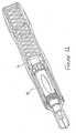
- Figure 1is a perspective view, partly in section, showing the injection device, in the condition in which it is supplied to a user, apart from the needle cover (which is described below after describing the main operation of the device).
- An energy source 1is provided at the rear of the device which, in this embodiment, is a gas cylinder similar to the type used in a conventional aerosol can or the like i.e. having a valve through which gas can be released at will and in a controlled manner.
- a springis used as the energy source in place of a gas cylinder and this embodiment is described later with reference to Figures 13 et seq.
- the valve 2 of the gas cylinderopens into a chamber 3, which in Figure 1 is of relatively small volume.
- the front wall of the chamber 3is defined by a ram 4 which has an annular seal 5 at the rear thereof in order to make the chamber 3 gas-tight.
- the rear wall of the chamber 3is defined by the back face of a generally cylindrical chamber housing 6.
- the forward part of the ram 4abuts or alternatively is integrally-formed with an inner housing 7 which closely surrounds a plunger 8 (and can therefore be referred to as the "plunger housing”).
- the rear of the plunger housingincludes four orthogonally placed tags 7A, which each have a "hammer head” or T-shape and whose tendency to spring radially outwardly is restricted by the diameter of the chamber housing 6. If the ram 4 is integrally formed with the plunger housing 7 as illustrated in Figures 13 and 14, the tags 7A are positioned at the end of flexible legs cut into the housing, so that the tags 7A can move radially, with respect to the ram 4 and remainder of housing 7.
- the plunger 8is the plunger of a syringe arrangement comprising a barrel 9 in which a predefined volume of liquid medicament is supplied and a needle 10 through which the medicament can be delivered to the patient.
- a nozzle 11 at the front end of the injection devicenormally conceals the needle 10 from the user's view.
- tags 7Bwhich each have a generally L shape and whose tendency to spring radially outwardly is restricted by the diameter of the chamber housing 6.
- the tags 7Beach abut the flange at the rear of barrel 9.
- tags 7Afor example tags that are not T-shaped, or means that push the plunger rather than pulling as in the described embodiment.
- Stage 1is the condition shown in Figures 1 and 2, i.e. the device as supplied to a user, and as described above.
- the medicamentis already present in the barrel 9 and the needle 10 is concealed from view within the nozzle 11.
- the plunger 8is fully withdrawn from the barrel 9 (because of the liquid medicament contained within the barrel) and the head of the plunger 8A abuts the tags 7A.
- the rear of the remainder of housing 7abuts the ram 4.
- the chamber 3is of minimal volume.
- Stage 2 of operationis the injection stage illustrated in Figures 3 and 4.
- downward forceis applied to the device in the direction indicated by the arrow F in Figure 2.
- This forcecauses the valve of the gas cylinder 1 to open, releasing gas into the chamber 3.
- the ram 4is urged forward, consequently urging tags 7A against the plunger 8.
- the cooperation of the tags 7B against the barrel 9means that the barrel is also urged forward, against the bias of a spring 12 (shown in Figure 3).
- the ram 4causes the plunger housing 7, the plunger 8, the barrel 9 and the needle 10 to move forwards.
- the tags 7BShortly after the plunger housing 7 starts to move forward, the tags 7B reach a lip in the chamber housing 6. The tags 7B spring radially outwardly over this lip, as shown in Figures 3 and 4. Once the tags 7B have sprung outwardly in this way, they are no longer in abutment with the barrel 9. This means that the barrel 9 (and hence needle 10) is no longer urged forwards because the forwardly-moving plunger housing 7, including tags 7B, are free to continue moving forward without contacting the barrel 9.
- the outward movement of the tags 7Ameans that the "hammer head" shape is no longer in contact with the enlarged head 8A of the plunger 8 and therefore the plunger 8 is no longer driven forward by the ram 4 and tags 7A.
- the plunger housing 7may continue further forward until an end stop is reached.
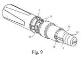
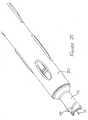
- Figure 9is a perspective view of the injection device which, in this Figure, includes a needle cover 15.
- the needle coveris shown in further detail in Figures 10 and 11 and is used to protect the needle end of the injection device during transit, storage and before use to deliver an injection.
- the needle cover 15has the further advantage of preventing accidental or unintended activation of the device, as it is not possible to fire the device with the needle cover 15 in place.
- the needle(which is in direct communication with the medicament in the barrel) is sealed from the outside environment before use. This is achieved by providing protection in the form of a rubber moulding 16 which covers the end of the needle, the rubber moulding 16 being surrounded by a nylon sheath 17.
- the rubber moulding and nylon sheath(the “needle protection") are fixed with respect to one another by a friction fit between one or more protrusions 16A on the rubber moulding and a corresponding one or more recesses 17A in the nylon sheath.
- the configuration of the needle protectiondepends upon the type of needle/barrel/plunger ("syringe assembly") employed in the injection device. It is envisaged that the injection device of the present invention could be assembled around a standard syringe assembly of known type (the selection thereof depending upon the required dose range, the type of medicament to be administered etc, for example). Different syringe assemblies may be supplied with slightly differing needle protection.
- an outer needle cover 15is provided which not only improves the aesthetic appearance of the injection device, before use, but also serves the function of facilitating the removal of the nylon sheath and rubber moulding.
- the needle cover 15is releasably retained on the front end of the injection device by the fit of annular protrusions 18 on part of the device housing with grooves 19 on the interior of the needle cover.
- the protrusions 18 and corresponding grooves 19preferably extend around two equally opposed 60° portions of the circumference of the nozzle 11.
- the grooves 19are located on one or more (preferably equally spaced) flexible legs 20 which are flexible compared to the rest of the needle cover 15, about point P shown in Figure 9. Forward of each groove 19 is provided an inwardly projecting tab 21 on each flexible leg 20. Each tab 21 abuts the rear of the nylon sheath 17.
- the usergrips the needle cover, preferably in a region having texture or other grip-improving means 22, and pulls in the direction indicated by the arrow in Figure 11.
- the flexibility of the legs 20permits the needle cover to ride over the protrusions 18, disengaging them from the grooves 19.
- the flexibility of the legs 20is minimal enough not to cause the tabs 21 to become disengaged from the rear of the nylon sheath 17.
- needle cover 15may be envisaged, suited to the particular type of syringe assembly used in the device, for example that described below with reference to Figure 25 et seq.
- Figures 13 and 14show more detail of an embodiment of the inner housing 7 in which the ram 4 is integral with the housing 7.
- the inner housingis injection moulded as a single piece having four orthogonally placed tags at each end thereof.
- Each tag 7A, 7Bis at the end of a resiliently flexible leg, cut out of the material of the housing 7, so that each leg (and its respective tag) is able to flex radially with respect to the remainder of the housing 7.
- the rear part of the inner housing 7constitutes the equivalent of the ram 4 described above.
- the ramis provided with an annular groove or recess 4A, into which the ball bearings 42 locate.
- the inner housing 7may also be provided with one or more guide means which, in the illustrated embodiment, take the form of elongate protrusions 7C. These protrusions 7C cooperate with corresponding recesses on the interior surface of the outer housing 30 so that, in use, relative axial movement of the inner and outer housings is guided.
- a spring 40is provided under compression at the rear of the device, intermediate the rear of a spring housing 41 and the ram 4.
- the spring 40is retained in its compressed condition by means of one or more ball bearings 42 sitting in annular recess 4A on the ram 4, the ball bearings 42 being wedged against the outer housing 30 and located in apertures 41C at the front of the spring housing 41.
- the spring housing 41interacts with the back of the outer housing 30 by means of an arrangement illustrated in Figure 17.
- the spring housing 41is provided with elongate slots 41B and generally circular apertures 41C.
- the corresponding part of the outer housingis provided with elongate protrusions 30B on the interior surface thereof, which fit into the slots 41B as illustrated in Figure 17.
- the ball bearings 42(not shown in Figure 17) fit through the circular apertures 41C.
- Figure 19shows the front part of the device at this stage, in more detail.
- FIG. 19the front part of the device is shown in more detail.
- the outer housing 30At the front of the outer housing 30, there are provided two annular grooves 30A and 30A' on the interior surface thereof.
- a spacer part 50is fixed with respect to the nozzle 11 and other components internal of the outer housing 30.
- the spacer part 50is provided with an exterior annular protrusion 51 which initially locates in the forwardmost groove 30A.
- the leading edge of forwardmost groove 30Ais generally blunt so that location of protrusion 51 therein (as illustrated in Figure 19) inhibits the user from pulling the outer housing 30 rearwardly off the spring housing 41 et al, which might dangerously expose the internal components of the device. It is difficult for a user to apply sufficient rearward force to cause the protrusion 51 to ride over the blunt leading edge.
- the trailing edge of the forwardmost groove 30A and both edges of the groove 30A'are curved or tapered.
- the usergrasps the outer housing 30 and effects forward movement of the outer housing 30 in relation to the spring housing 41. As shown in Figure 20, the forward movement causes the protrusion 51 to disengage from the forwardmost groove 30A and, as the outer housing 30 moves forward with respect to the spacer 50, the protrusion 51 engages in the rearmost groove 30A'.
- Figure 21shows the device in the same condition as in Figure 20 i.e. wherein forward movement of the outer housing in relation to the spring housing has caused the protrusion 51 to be engaged in the rearmost groove 30A'.
- the forward-moving ram 4causes the inner housing 7 to deliver the injection as previously described. This is illustrated in Figure 21 (Stage 2 as previously described) and Figure 22 (Stage 3 as previously described).
- Figure 23shows the position in which the injection has been fully delivered and the needle caused to retract back inside the nozzle (final stage as previously described).
- the ball bearings 42are replaced by a living joint, moveable into undercut area 30A" and out of engagement with the ram 4.
- the protrusion 51 and grooves 30A, 30A'are replaced or supplemented by a ratchet arrangement described hereafter.
- a spring housingis provided which has a substantially square cross-section. A portion of the inside of the outer housing 30 is correspondingly shaped with a square cross-section so that the spring housing and outer housing closely fit together but relative axial movement between them is possible. Relative rotational movement between them is substantially prevented by the square cross-section. At least one surface of the square cross-section spring housing is provided with a plurality of barbs, protrusions, ratchet teeth or the like which cooperate with an inwardly-depending protrusion or tag on the inside of the outer housing.
- the ratchet arrangementperforms the same function as protrusion 51 and grooves 30A, 30A' i.e. to control forward movement of the outer housing 30 in relation to the spring housing 41.
- the ratchet arrangementmay provide further advantages, for example:
- the spring housinghas at least one flat surface on which the barbs, protrusions, ratchet teeth or the like are disposed; the remainder of the spring housing may be of any cross-sectional shape so long as the inside of the outer housing is correspondingly shaped.
- the barrel 9may be provided with a transparent window 9a which, in use, is aligned with a window 32 in the outer housing (see Figure 24) so that the liquid medicament is visible.
- the plunger housing 7becomes visible as it moves forwardly intermediate the barrel 9 and outer housing. As the plunger housing 7 moves forwardly, it progressively obscures the window 9a thus giving a visual indication to the user of the progress of the injection.
- the window 9amay be completely obscured by the plunger housing 7 when the injection is complete.
- the plunger housing 7may be brightly coloured e.g. red to increase its visibility through the window 30.
- tags 7AWhen the plunger housing 7 has moved forward sufficiently for tags 7A to reach recesses 13, the tags 7A will have an increased tendency to spring outwardly into the position in which they had been previously stored, ensuring efficient operation of the device.
- Figures 26 and 27show an alternative embodiment of the needle cover 15. Like parts are given the same reference numerals as in Figure 11.
- the needle cover 15is releasably retained on the front end of the injection device by the fit of protrusions 11A on the exterior of the nozzle 11 with corresponding recesses on the interior of the needle cover 15.
- the protrusions 11Amay take the form of a single helical protrusion as illustrated in Figure 25, or alternatively several discrete protrusions may be used.
- a floating rivet 35which has rearwardly directed barbed fingers 36 which pass through an aperture in the front end of the sheath 17.
- the protrusions 11A the barbed fingers 36 and the interaction of the nozzle with the needle cover 15 at surface 15Amean that the nozzle 11 and associated components are prevented from moving axially with respect to the housing 30 in the situation illustrated in Figure 26. This means that the device cannot be inadvertently fired whilst the needle cover 15 is still in place.
- the usergrips the needle cover and pulls in the direction indicated by the arrow in Figure 26, using a twisting motion to cause the needle cover to ride along the nozzle guided by the helical protrusion 11A.
- the floating rivet 35allows the needle cover 15 to be twisted in order for it to move along helical protrusion 11A, but the sheath 17 does not twist and is simply pulling axially off the needle. This means there is no risk of damage to the needle 10 caused by twisting forces.
- the barbed fingers 36pull the sheath 17 with sufficient force to disengage the needle 10 from the rubber moulding 16.
- the entire moulding 16, nylon sheath 17 and needle cover 15can be removed from the injection device and discarded, so that the injection device is then ready to use. Removal of the needle cover 15 has the second function of allowing the nozzle etc to be free to move axially with respect to the housing 30, which enables the device to be fired as described above.
- a further embodiment of the present inventionis envisaged wherein the needle is exposed upon removal of the needle cover 15.
- Such an embodimentmay be suitable for users where needle-phobia is not a concern and where the complexity (and hence cost) of the device can be reduced by eliminating the need for the first stage (i.e. the forward movement of the needle out of the nozzle 11).
- the optional needle cover 15may be omitted from such an embodiment.
- the injection device of the present inventionmay be supplied separately from and then assembled around a standard syringe assembly (needle/barrel/plunger) of known type.
- the device of the present inventioncould be operable with a standard cartridge or vial of medicament (containing a volume of medicament from which several doses of user-defined volume can be provided) instead of a syringe assembly.
- the needlecould be removable and replaceable so that the device could be reused until the medicament cartridge is empty.
Landscapes
- Health & Medical Sciences (AREA)
- Engineering & Computer Science (AREA)
- General Health & Medical Sciences (AREA)
- Public Health (AREA)
- Anesthesiology (AREA)
- Biomedical Technology (AREA)
- Heart & Thoracic Surgery (AREA)
- Hematology (AREA)
- Life Sciences & Earth Sciences (AREA)
- Animal Behavior & Ethology (AREA)
- Veterinary Medicine (AREA)
- Vascular Medicine (AREA)
- Environmental & Geological Engineering (AREA)
- Infusion, Injection, And Reservoir Apparatuses (AREA)
- Injection Moulding Of Plastics Or The Like (AREA)
- Chemical Or Physical Treatment Of Fibers (AREA)
- Polarising Elements (AREA)
- Eye Examination Apparatus (AREA)
- Noodles (AREA)
- Diaphragms For Electromechanical Transducers (AREA)
Abstract
Description
- This invention relates to the field of injection devices for the administration of liquid medication, for example, insulin or growth hormone.
- One type of injection device is known as a mini-needle or micro-needle device. These devices comprise a pressurised ("forced") injection system and have a needle which is shorter than that of conventional needle systems. The needle is normally hidden which is advantageous both for avoiding needle stick injuries and for minimising trauma to needle-phobic patients. The needle is hidden both before and after the injection is delivered, appearing only for the duration of the injection. Mini needle devices can typically deliver a larger volume of medication than needle-free devices and can deliver faster than conventional needle systems.
- One such known device is described in
WO00/09186 - The device of
WO 00/09186 - An alternative way of concealing the needle after an injection has been delivered is described in
US6544234 (BD Medico SARL), which discloses an injection device in which the needle is concealed before injection, but the configuration of the device is such that the needle cannot retract after injection, Instead, there is a moveable needle protection sleeve which is displaced by a compression spring when the needle is pulled out of the subcutaneous tissue in order to conceal the needle from the patient. WO03/097133 - Although the present invention may relate to mini-needle or jet injection devices, the invention is equally applicable to other types of injection device, for example those for deep-penetrating muscular injection as well as those which are for shallower, subcutaneous, injection.
- According to a first aspect of the present invention there is provided an injection device comprising an outer housing adapted to receive
a barrel for holding a volume of a medicament;
a needle at one end of the barrel, the needle and barrel being such that at least part of the needle is axially moveable in and out of said outer housing but is biased to be normally wholly inside said housing;
a plunger, axially moveable within the barrel;
an inner housing intermediate the outer housing and the barrel and plunger; and
an energy source in communication with said inner housing,
wherein the inner housing is moveable by the energy source between three positions, namely
a first position in which the inner housing is in communication with both the plunger and the barrel such that, in use, the plunger and barrel are movable axially so as to move at least part of said needle out of the outer housing;
a second position in which the inner housing is in communication with the plunger but not the barrel such that, in use, said plunger is movable axially into said barrel so as to expel medicament through the needle; and
a third position in which the inner housing is in communication with neither the plunger nor the barrel such that, in use, the plunger and barrel are able to retract in order to retract the needle into the outer housing. - The injection device according to the present invention provides a simple and cost-effective means of delivering medicament through a retractable needle. If desired, the device is able to deliver medicament to a depth beyond the length of the needle because of the propulsive force provided by the energy source. As mentioned above, the injection device is equally suitable for needle-assisted jet injection (delivering medicament to a depth beyond the length of the needle), conventional injection (to the depth of the needle penetration), or even to a user-adjustable needle penetration depth.
- The device requires that the needle (and hence also the barrel to which it is normally fixed) is moved axially so that the needle can appear beyond the end of the nozzle for the duration of the injection, after which the needle retracts automatically, out of sight of the user. The device also requires that the plunger is moved axially (into the barrel) so that medicament is ejected. The overall complexity of the injection device is significantly reduced by both of these requirements being effected by one component, namely the inner housing.
- Preferably, the injection device comprises an outer housing inside which is located said barrel, said needle and said plunger.
- Preferably, said inner housing includes one or more radially flexible tags, each preferably located at the end of a resiliently flexible leg.
- Preferably, one or more of said tags are situated at the rear end of the inner housing and are moveable radially into and out of communication with the plunger. In one embodiment, the tags are biased radially inwardly into communication with the plunger, preferably by communication with the outer housing. Alternatively, the tags are stored in their relaxed condition, before an injection is initiated.
- Each rear tag may be moveable out of communication with the plunger when aligned with a corresponding recess in the outer housing. Preferably, each rear tag is substantially T-shaped. One leg of the T-shape enables the rear tag to hook over the plunger and, effectively, pull the plunger forward (in the first and second positions mentioned above). The other leg of the T-shape enables the rear tag to move radially outwardly to catch in a recess in the housing (in the third position mentioned above).
- Preferably, one or more of said tags are situated at the forward end of the inner housing and are moveable radially into and out of communication with the barrel. In one embodiment, the forward tags are biased radially inwardly into communication with the barrel, preferably by communication with the outer housing. Alternatively, the forward tags are stored in their relaxed condition, before initiating an injection.
- Each forward tag may be moveable out of communication with the barrel when aligned with a corresponding recess in the outer housing. Preferably, each rear tag is substantially L-shaped.
- In a preferred embodiment, said energy source is a compressed gas. Alternatively, said energy source is a spring.
- Preferably, the injection device further includes means for allowing the inner housing to move axially only forward with respect to the outer housing. Ideally, said means is an arrangement of serrations, barbs, ratchet teeth or the like intermediate the housings.
- Preferably, the injection device further comprises guide means for guiding, in use, the relative axial movement of the inner and outer housings, the guide means preferably comprising one or more protrusions on said inner housing which, in use, cooperate with corresponding recesses on an interior surface of said outer housing.
- Preferably, said needle is biased to be normally wholly inside said housing by means of a spring intermediate the barrel and the outer housing.
- In one embodiment, the needle is removable from the device, this being of benefit in applications where the device is reusable (for example if a multiple-use cartridge of medicament is utilised).
- In a further embodiment, said needle, barrel and plunger are removable from said device. It is intended that the device of the present invention could be constructed around a standard needle, barrel and plunger of known type.
- Preferably, the injection device further includes a removable needle cover which protects the needle during storage and before use. Advantageously, said needle cover includes means for pulling a protective rubber sheath or the like from said needle when said needle cover is removed from the device. Said pulling means may include a floating rivet intermediate the needle cover and the protective rubber sheath or the like, whereby twisting forces applied to said needle cover are substantially prevented from being transmitted to said rubber sheath or the like.
- Preferably, the presence of said needle cover on said device serves as a safety lock, substantially preventing relative forward movement of said outer housing.
- In a preferred form, the injection device further comprises a viewing window in said barrel aligned with a viewing window in said outer housing such that said medicament can be viewed by a user prior to an injection taking place. Preferably, in use during an injection, said inner housing moves intermediate said viewing window in the outer housing and said barrel so as to obscure the window in the barrel from the user's view.
- Preferably, the injection device includes means for emitting an audible and/or physical indication to a user that the injection is complete.
- Preferred embodiments of the present invention will now be more particularly described, by way of example only, with reference to the accompanying drawings wherein:
- Figure 1 is a perspective view, partly in section, showing the injection device, in the condition in which it is supplied to a user, apart from the needle cover;
- Figure 2, drawn to a larger scale, shows detail of part of the device shown in Figure 1;
- Figure 3 is a perspective view, partly in section, showing the injection device, during an injection;
- Figure 4, drawn to a larger scale, shows detail of part of the device shown in Figure 3;
- Figure 5 is a perspective view, partly in section, showing the injection device, with the plunger fully depressed into the barrel;
- Figure 6, drawn to a larger scale, shows detail of part of the device shown in Figure 5;
- Figure 7 is a perspective view, partly in section, showing the injection device, after use and safe to dispose of;
- Figure 8, drawn to a larger scale, shows detail of part of the device shown in Figure 7;
- Figure 9 is a perspective view of the device, including the needle cover;
- Figure 10 is perspective view, partly in section, showing detail of the needle cover;
- Figure 11 is perspective view, partly in section, showing detail of the needle cover part way through being removed from the injection device;
- Figure 12 is a schematic view showing the relationship between
tags 7A andram 4, in one embodiment of the invention; - Figure 13 is a perspective view of the inner housing (also referred to as the "plunger housing");
- Figure 14 is a side view of the inner housing of Figure 13;
- Figure 15 is a perspective view, partly in section, showing an alternative embodiment of the injection device, in the condition in which it is supplied to a user;
- Figure 16, drawn to a larger scale, shows detail of the rear end of the device shown in Figure 15;
- Figure 17 shows detail of the interaction between the
spring housing 41 and the rear of theouter housing 30; - Figure 18 is a perspective view, partly in section, showing the injection device with the needle cover removed, immediately prior to initiating an injection;
- Figure 19 is a perspective view, partly in section and drawn to a larger scale, showing the front part of the device immediately before initiating an injection;
- Figure 20 is a perspective view, partly in section, showing the front part of the device at the start of an injection;
- Figure 21 is a perspective view showing the device in the same condition as Figure 20, i.e. at the start of an injection with the needle emerging from the end of the device and the plunger beginning to travel down the barrel;
- Figure 22 is a perspective view, partly in section, showing the injection device with the plunger fully depressed into the barrel;
- Figure 23 is a perspective view, partly in section, showing the injection device after use and with the needle retracted into the device;
- Figure 24 is a perspective view of the assembled device, including the needle cover;
- Figure 25 is a schematic view of part of the front end of the device, showing the helical protrusion on the nozzle.
- Figure 26 is perspective view, partly in section, showing detail of the needle cover; and
- Figure 27 is perspective view, partly in section, showing detail of the needle cover after removal from the device.
- Throughout the following description, reference to a "forward" direction means the direction which is towards the patient when the injection device is in use. The "forward" end of the injection device is the end nearest the patient's skin when the device is in use. Similarly, reference to a "rearward" direction means the direction which is away from the patient and the "rearward" end of the device is the end furthest from the patient's skin when the injection device is in use.
- Figure 1 is a perspective view, partly in section, showing the injection device, in the condition in which it is supplied to a user, apart from the needle cover (which is described below after describing the main operation of the device).
- The principal components of the device will now be described with reference to Figures 1 and 2. An
energy source 1 is provided at the rear of the device which, in this embodiment, is a gas cylinder similar to the type used in a conventional aerosol can or the like i.e. having a valve through which gas can be released at will and in a controlled manner. In an alternative embodiment of the invention, a spring is used as the energy source in place of a gas cylinder and this embodiment is described later with reference to Figures 13 et seq. - The valve 2 of the gas cylinder opens into a
chamber 3, which in Figure 1 is of relatively small volume. The front wall of thechamber 3 is defined by aram 4 which has anannular seal 5 at the rear thereof in order to make thechamber 3 gas-tight. The rear wall of thechamber 3 is defined by the back face of a generallycylindrical chamber housing 6. - The forward part of the
ram 4 abuts or alternatively is integrally-formed with aninner housing 7 which closely surrounds a plunger 8 (and can therefore be referred to as the "plunger housing"). The rear of the plunger housing includes four orthogonally placedtags 7A, which each have a "hammer head" or T-shape and whose tendency to spring radially outwardly is restricted by the diameter of thechamber housing 6. If theram 4 is integrally formed with theplunger housing 7 as illustrated in Figures 13 and 14, thetags 7A are positioned at the end of flexible legs cut into the housing, so that thetags 7A can move radially, with respect to theram 4 and remainder ofhousing 7. - The hammer head of each
tag 7A hooks over theenlarged head 8A of theplunger 8, so that thetags 7A are in contact with theplunger head 8A, as shown best in Figure 2.
Theplunger 8 is the plunger of a syringe arrangement comprising abarrel 9 in which a predefined volume of liquid medicament is supplied and aneedle 10 through which the medicament can be delivered to the patient. Anozzle 11 at the front end of the injection device normally conceals theneedle 10 from the user's view. Aspring 12, positioned between the outer housing and thebarrel 9 biases the needle to be normally wholly within thenozzle 11. - At the front end of the
plunger housing 7, there are further orthogonally placedtags 7B, which each have a generally L shape and whose tendency to spring radially outwardly is restricted by the diameter of thechamber housing 6. Thetags 7B each abut the flange at the rear ofbarrel 9. - Other means of interaction between the inner housing and the plunger may be envisaged, instead of
tags 7A, for example tags that are not T-shaped, or means that push the plunger rather than pulling as in the described embodiment. - There are four main stages in the operation of the device.
Stage 1 is the condition shown in Figures 1 and 2, i.e. the device as supplied to a user, and as described above. The medicament is already present in thebarrel 9 and theneedle 10 is concealed from view within thenozzle 11. Theplunger 8 is fully withdrawn from the barrel 9 (because of the liquid medicament contained within the barrel) and the head of theplunger 8A abuts thetags 7A. The rear of the remainder ofhousing 7 abuts theram 4. Thechamber 3 is of minimal volume. - Stage 2 of operation is the injection stage illustrated in Figures 3 and 4. With the injection device held against the patient's skin at the injection site, downward force is applied to the device in the direction indicated by the arrow F in Figure 2. This force causes the valve of the
gas cylinder 1 to open, releasing gas into thechamber 3. As thechamber 3 fills with gas, theram 4 is urged forward, consequently urgingtags 7A against theplunger 8. As thetags 7A, and hence theplunger housing 7, are urged forward, the cooperation of thetags 7B against thebarrel 9 means that the barrel is also urged forward, against the bias of a spring 12 (shown in Figure 3). As thebarrel 9 moves forward, so does theneedle 10 which is attached thereto and so the needle protrudes out of thenozzle 11 sufficiently to enable an injection to be delivered. Therefore, initially, theram 4 causes theplunger housing 7, theplunger 8, thebarrel 9 and theneedle 10 to move forwards. - Shortly after the
plunger housing 7 starts to move forward, thetags 7B reach a lip in thechamber housing 6. Thetags 7B spring radially outwardly over this lip, as shown in Figures 3 and 4. Once thetags 7B have sprung outwardly in this way, they are no longer in abutment with thebarrel 9. This means that the barrel 9 (and hence needle 10) is no longer urged forwards because the forwardly-movingplunger housing 7, includingtags 7B, are free to continue moving forward without contacting thebarrel 9. - Therefore, once the device has reached the condition illustrated in Figures 3 and 4, continued forward movement of the
ram 4 andplunger housing 7 causes theplunger 8 to be urged forward into thebarrel 9. This expels the liquid medicament from thebarrel 9, through theneedle 10 to deliver an injection. It is the cooperation of thetags 7A with theenlarged head 8A of the plunger which transmits the forward force from theram 4/housing 7 to theplunger 8. - The third stage in the operation of the device is illustrated in Figures 5 and 6. When the
plunger 8 is depressed into thebarrel 9, the desired dose of medicament is delivered into the patient. At this point, thetags 7A reach recesses 13 cut into theplunger housing 6 whereupon they are able to spring radially outwardly into those recesses (as illustrated in Figures 5 and 6). An audible click may be emitted which indicates to the user that the injection is complete. In addition, the user may "feel" that the injection is complete as a result of thetags 7A locating inrecesses 13. - The outward movement of the
tags 7A means that the "hammer head" shape is no longer in contact with theenlarged head 8A of theplunger 8 and therefore theplunger 8 is no longer driven forward by theram 4 andtags 7A. Theplunger housing 7 may continue further forward until an end stop is reached. - The final stage in the operation of the device is illustrated in Figures 7 and 8. With the
tags 7A located withinrecesses 13, neither theplunger 8 nor thebarrel 9 is impeded by any part of theplunger housing 7. Therefore thespring 12, which had been compressed by the forward motion of thebarrel 9, urges thebarrel 9 and hence theplunger 8 backwards until theram 4 prevents further backward movement thereof. The backward movement is sufficient to cause theneedle 10 to retract into thenozzle 11 so that it is no longer visible to the user and safe from the risk of causing a needle-stick injury. The used injection device can then be safely disposed of. - Blow-back is prevented by the provision of
serrations 14 which guide the relative movement of thechamber housing 6 and the outermost housing. These serrations only permit relative movement in one direction, i.e. thechamber housing 6 moving forward with respect to the outermost housing. - Figure 9 is a perspective view of the injection device which, in this Figure, includes a
needle cover 15. The needle cover is shown in further detail in Figures 10 and 11 and is used to protect the needle end of the injection device during transit, storage and before use to deliver an injection. Theneedle cover 15 has the further advantage of preventing accidental or unintended activation of the device, as it is not possible to fire the device with theneedle cover 15 in place. - Regulations require that the needle (which is in direct communication with the medicament in the barrel) is sealed from the outside environment before use. This is achieved by providing protection in the form of a
rubber moulding 16 which covers the end of the needle, therubber moulding 16 being surrounded by anylon sheath 17. The rubber moulding and nylon sheath (the "needle protection") are fixed with respect to one another by a friction fit between one ormore protrusions 16A on the rubber moulding and a corresponding one ormore recesses 17A in the nylon sheath. - The configuration of the needle protection depends upon the type of needle/barrel/plunger ("syringe assembly") employed in the injection device. It is envisaged that the injection device of the present invention could be assembled around a standard syringe assembly of known type (the selection thereof depending upon the required dose range, the type of medicament to be administered etc, for example). Different syringe assemblies may be supplied with slightly differing needle protection.
- The nylon sheath and rubber moulding are firmly fixed on the
needle 10 and it is difficult, if not impossible, for a patient to pull them from the needle using his/her fingers alone because of their position inside thenozzle 11. Therefore anouter needle cover 15 is provided which not only improves the aesthetic appearance of the injection device, before use, but also serves the function of facilitating the removal of the nylon sheath and rubber moulding. - The
needle cover 15 is releasably retained on the front end of the injection device by the fit ofannular protrusions 18 on part of the device housing withgrooves 19 on the interior of the needle cover. Theprotrusions 18 andcorresponding grooves 19 preferably extend around two equally opposed 60° portions of the circumference of thenozzle 11. - The
grooves 19 are located on one or more (preferably equally spaced)flexible legs 20 which are flexible compared to the rest of theneedle cover 15, about point P shown in Figure 9. Forward of eachgroove 19 is provided an inwardly projectingtab 21 on eachflexible leg 20. Eachtab 21 abuts the rear of thenylon sheath 17. - Turning now to Figure 11, when it is desired to remove the
needle cover 15 from the device, the user grips the needle cover, preferably in a region having texture or other grip-improvingmeans 22, and pulls in the direction indicated by the arrow in Figure 11. The flexibility of thelegs 20 permits the needle cover to ride over theprotrusions 18, disengaging them from thegrooves 19. The flexibility of thelegs 20 is minimal enough not to cause thetabs 21 to become disengaged from the rear of thenylon sheath 17. - Therefore, as the
needle cover 15 is pulled in the direction indicated by the arrow, thetabs 21 are urged against the rear of thenylon sheath 17 and sufficient force can be applied thereby to disengage theneedle 10 from therubber moulding 16. In this way, theentire moulding 16,nylon sheath 17 and needle cover 15 can be removed from the injection device and discarded, so that the injection device is then ready to use. - Other types of
needle cover 15 may be envisaged, suited to the particular type of syringe assembly used in the device, for example that described below with reference to Figure 25 et seq. - Figures 13 and 14 show more detail of an embodiment of the
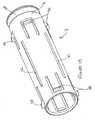
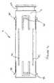
inner housing 7 in which theram 4 is integral with thehousing 7. - The inner housing is injection moulded as a single piece having four orthogonally placed tags at each end thereof. Each
tag housing 7, so that each leg (and its respective tag) is able to flex radially with respect to the remainder of thehousing 7. - The rear part of the
inner housing 7 constitutes the equivalent of theram 4 described above. The ram is provided with an annular groove orrecess 4A, into which theball bearings 42 locate. - The
inner housing 7 may also be provided with one or more guide means which, in the illustrated embodiment, take the form ofelongate protrusions 7C. Theseprotrusions 7C cooperate with corresponding recesses on the interior surface of theouter housing 30 so that, in use, relative axial movement of the inner and outer housings is guided. - A spring-powered embodiment of the injection device is described below with reference to Figure 15 et seq.
- In this embodiment, there is a generally cylindrical
outer housing 30 extending all the way from the rear of the device to theneedle cover 15. Thegas cylinder 1 and valve 2 are replaced by a spring-powered energy source. Referring particularly to Figure 16, aspring 40 is provided under compression at the rear of the device, intermediate the rear of aspring housing 41 and theram 4. Thespring 40 is retained in its compressed condition by means of one ormore ball bearings 42 sitting inannular recess 4A on theram 4, theball bearings 42 being wedged against theouter housing 30 and located inapertures 41C at the front of thespring housing 41. Thespring housing 41 interacts with the back of theouter housing 30 by means of an arrangement illustrated in Figure 17. - The
spring housing 41 is provided withelongate slots 41B and generallycircular apertures 41C. The corresponding part of the outer housing is provided withelongate protrusions 30B on the interior surface thereof, which fit into theslots 41B as illustrated in Figure 17. The ball bearings 42 (not shown in Figure 17) fit through thecircular apertures 41C. - In Figure 15 it can be seen that the front end of the
outer housing 30 is in close relation, or abutting, theneedle cover 15. This substantially prevents any forward movement of theouter housing 30 in relation to thespring housing 41 and other components. - In Figure 18, the needle cover has been removed and it is now possible to place the device against the user's leg (or other injection site) ready to initiate an injection.
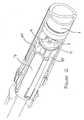
- Figure 19 shows the front part of the device at this stage, in more detail.
- Referring now to Figures 19 and 20, the front part of the device is shown in more detail. At the front of the
outer housing 30, there are provided twoannular grooves spacer part 50 is fixed with respect to thenozzle 11 and other components internal of theouter housing 30. Thespacer part 50 is provided with an exteriorannular protrusion 51 which initially locates in theforwardmost groove 30A. - The leading edge of
forwardmost groove 30A is generally blunt so that location ofprotrusion 51 therein (as illustrated in Figure 19) inhibits the user from pulling theouter housing 30 rearwardly off thespring housing 41 et al, which might dangerously expose the internal components of the device. It is difficult for a user to apply sufficient rearward force to cause theprotrusion 51 to ride over the blunt leading edge. - The trailing edge of the
forwardmost groove 30A and both edges of thegroove 30A' are curved or tapered. - To initiate an injection, the user grasps the
outer housing 30 and effects forward movement of theouter housing 30 in relation to thespring housing 41. As shown in Figure 20, the forward movement causes theprotrusion 51 to disengage from theforwardmost groove 30A and, as theouter housing 30 moves forward with respect to thespacer 50, theprotrusion 51 engages in therearmost groove 30A'. - Referring now to Figures 18 and 21, the relationship between the
ram 4,ball bearings 42 andspring housing 41 is described in more detail. In the first position, shown in Figure 18, theball bearings 42 sit in theannular groove 4A in theram 4 and are wedged in place in theapertures 41C at the front of thespring housing 41. - Figure 21 shows the device in the same condition as in Figure 20 i.e. wherein forward movement of the outer housing in relation to the spring housing has caused the
protrusion 51 to be engaged in therearmost groove 30A'. - In this position, the
spring housing 41 has moved closer to the rear of theouter housing 30. This relative axial movement is sufficient to cause theapertures 41C to retreat back past an undercutarea 30A" inside theouter housing 30. Theball bearings 42 are now free to move radially out of theapertures 41C and into said undercutarea 30A" , out of engagement with theram 4. Theram 4 is now free to travel forwards in the direction indicated by the arrow in Figure 21, under the power of thespring 40. - The forward-moving
ram 4 causes theinner housing 7 to deliver the injection as previously described. This is illustrated in Figure 21 (Stage 2 as previously described) and Figure 22 (Stage 3 as previously described). - Figure 23 shows the position in which the injection has been fully delivered and the needle caused to retract back inside the nozzle (final stage as previously described).
- In an alternative embodiment (not illustrated), the
ball bearings 42 are replaced by a living joint, moveable into undercutarea 30A" and out of engagement with theram 4. - In another embodiment (not illustrated), the
protrusion 51 andgrooves outer housing 30 is correspondingly shaped with a square cross-section so that the spring housing and outer housing closely fit together but relative axial movement between them is possible. Relative rotational movement between them is substantially prevented by the square cross-section. At least one surface of the square cross-section spring housing is provided with a plurality of barbs, protrusions, ratchet teeth or the like which cooperate with an inwardly-depending protrusion or tag on the inside of the outer housing. - The ratchet arrangement performs the same function as
protrusion 51 andgrooves outer housing 30 in relation to thespring housing 41. The ratchet arrangement may provide further advantages, for example: - Improved strength;
- Rotational alignment between spring housing and outer housing;
- Improved resistance to rearward force generated by the user pushing the device hard into the injection site;
- Improved resistance to the user pulling the outer housing rearwardly off the device, the ratchet teeth permitting forward movement of the outer housing only;
- Improved defining of the relative axial position of the outer housing and internal components of the device.
- Alternative embodiments are envisaged in which, instead of a square cross-section, the spring housing has at least one flat surface on which the barbs, protrusions, ratchet teeth or the like are disposed; the remainder of the spring housing may be of any cross-sectional shape so long as the inside of the outer housing is correspondingly shaped.
- Other modifications to the injection device are illustrated in Figure 13 et seq which are equally applicable to the gas-powered embodiment described earlier.
- The
barrel 9 may be provided with a transparent window 9a which, in use, is aligned with awindow 32 in the outer housing (see Figure 24) so that the liquid medicament is visible. During the injection (i.e. during firing of the injection device), theplunger housing 7 becomes visible as it moves forwardly intermediate thebarrel 9 and outer housing. As theplunger housing 7 moves forwardly, it progressively obscures the window 9a thus giving a visual indication to the user of the progress of the injection. The window 9a may be completely obscured by theplunger housing 7 when the injection is complete. Theplunger housing 7 may be brightly coloured e.g. red to increase its visibility through thewindow 30. - It is observed that plastics of the type which may be used to form the
plunger housing 7 will, over time, tend to gain a memory of the position in which they are stored. It is essential for operation of the device that thetags 7A spring properly into and out of engagement with theenlarged head 8A of the plunger. Therefore, as visible in Figure 18, atapered surface 31 is provided on the interior of theouter housing 30. This enables thetags 7A to be stored in their "relaxed" position, i.e. sprung radially-outwardly to abut theouter housing 30, as illustrated in Figure 18. - When an injection is initiated as shown in Figure 21, the forward movement of the
outer housing 30 in relation to theplunger housing 7 causes thetags 7A to ride up the taperedsurface 31 and into engagement with theenlarged head 8A of the plunger. - When the
plunger housing 7 has moved forward sufficiently fortags 7A to reachrecesses 13, thetags 7A will have an increased tendency to spring outwardly into the position in which they had been previously stored, ensuring efficient operation of the device. - Figures 26 and 27 show an alternative embodiment of the
needle cover 15. Like parts are given the same reference numerals as in Figure 11. In the Figure 26 embodiment, theneedle cover 15 is releasably retained on the front end of the injection device by the fit of protrusions 11A on the exterior of thenozzle 11 with corresponding recesses on the interior of theneedle cover 15. - The protrusions 11A may take the form of a single helical protrusion as illustrated in Figure 25, or alternatively several discrete protrusions may be used.
- At the front end of the
needle cover 15 is a floatingrivet 35 which has rearwardly directedbarbed fingers 36 which pass through an aperture in the front end of thesheath 17. - The protrusions 11A the
barbed fingers 36 and the interaction of the nozzle with theneedle cover 15 atsurface 15A mean that thenozzle 11 and associated components are prevented from moving axially with respect to thehousing 30 in the situation illustrated in Figure 26. This means that the device cannot be inadvertently fired whilst theneedle cover 15 is still in place. - When it is desired to remove the
needle cover 15 from the device, the user grips the needle cover and pulls in the direction indicated by the arrow in Figure 26, using a twisting motion to cause the needle cover to ride along the nozzle guided by the helical protrusion 11A. - The floating
rivet 35 allows theneedle cover 15 to be twisted in order for it to move along helical protrusion 11A, but thesheath 17 does not twist and is simply pulling axially off the needle. This means there is no risk of damage to theneedle 10 caused by twisting forces. - As the
needle cover 15 is pulled in the direction indicated by the arrow, thebarbed fingers 36 pull thesheath 17 with sufficient force to disengage theneedle 10 from therubber moulding 16. In this way, theentire moulding 16,nylon sheath 17 and needle cover 15 can be removed from the injection device and discarded, so that the injection device is then ready to use. Removal of theneedle cover 15 has the second function of allowing the nozzle etc to be free to move axially with respect to thehousing 30, which enables the device to be fired as described above. - When the end of the protrusion 11A is reached, the
needle cover 15 is disengaged from thenozzle 11 as illustrated in Figure 27. - A further embodiment of the present invention is envisaged wherein the needle is exposed upon removal of the
needle cover 15. Such an embodiment may be suitable for users where needle-phobia is not a concern and where the complexity (and hence cost) of the device can be reduced by eliminating the need for the first stage (i.e. the forward movement of the needle out of the nozzle 11). Theoptional needle cover 15 may be omitted from such an embodiment. As mentioned above, it is possible that the injection device of the present invention may be supplied separately from and then assembled around a standard syringe assembly (needle/barrel/plunger) of known type. - In a further development, it is envisaged that it would be readily possible to adapt the device of the present invention to be operable with a standard cartridge or vial of medicament (containing a volume of medicament from which several doses of user-defined volume can be provided) instead of a syringe assembly. In such case the needle could be removable and replaceable so that the device could be reused until the medicament cartridge is empty.
Claims (29)
- An injection device comprising an outer housing (30) adapted to receive:a barrel for holding a volume of a medicament;a needle (10) at one end of the barrel, the needle and barrel being such that at least part of the needle is axially moveable in and out of said outer housing (30) but is biased to be normally wholly inside said housing; anda plunger (8), axially moveable within the barrel,wherein the injection device further comprises:an inner housing (7) intermediate the outer housing and the barrel and plunger; andan energy source (1; 40) in communication with said inner housing (7),the device being moveable between two positions, namelya first position in which the device acts on the barrel such that, in use, the plunger and barrel are movable axially so as to move at least part of said needle out of the outer housing; anda second position in which the device acts on the plunger but not the barrel such that, in use, said plunger is movable axially into said barrel so as to expel medicament through the needle;characterised in that said inner housing (7) is moveable by the energy source between three positions, namely
said first position in which the inner housing has one or more radially flexible tags (7B) in communication with the barrel such that, in use, the plunger and barrel are movable axially so as to move at least part of said needle out of the outer housing;
said second position in which the inner housing has one or more radially flexible tags (7A) in communication with the plunger but not the barrel such that, in use, said plunger is movable axially into said barrel so as to expel medicament through the needle; and
a third position in which said radially flexible tags (7A, 7B) on the inner housing are in communication with neither the plunger nor the barrel such that, in use, the plunger and barrel are able to retract in order to retract the needle into the outer housing. - The injection device of claim 1 inside which is located
said barrel for holding a volume of a medicament;
said needle (10) at one end of the barrel; and
said plunger (8), axially moveable within the barrel. - An injection device as claimed in claim 1 or claim 2 further comprising a spring housing (41) intermediate the outer housing (30) and the inner housing (7).
- An injection device as claimed in any of the preceding claims wherein one or more of said tags is located at the end of a resiliently flexible leg.
- An injection device as claimed in any of the preceding claims wherein one or more of said tags are situated at the rear end of the inner housing and are moveable radially into and out of communication with the plunger.
- An injection device as claimed in any of claims 3-5 wherein said tags are biased radially inwardly into communication with said plunger, preferably by communication with said spring housing.
- An injection device as claimed in any of the preceding claims wherein said tags are stored in their relaxed condition, before initiating an injection.
- An injection device as claimed in any of claims 3-7 wherein each rear tag is moveable out of communication with the plunger when aligned with a corresponding recess in the spring housing.
- An injection device as claimed in any of the preceding claims wherein each rear tag is substantially T-shaped.
- An injection device as claimed in any of claims 1-4 wherein one or more of said tags are situated at the forward end of the inner housing and are moveable radially into and out of communication with the barrel.
- An injection device as claimed in claim 10 wherein said forward tags are biased radially inwardly into communication with said barrel, preferably by communication with said spring housing.
- An injection device as claimed in claim 10 or claim 11 wherein said forward tags are stored in their relaxed condition, before initiating an injection.
- An injection device as claimed in any of claims 10-12 wherein each forward tag is moveable out of communication with the barrel when aligned with a corresponding recess in the spring housing.
- An injection device as claimed in any of claims 10-13 wherein each forward tag is substantially L-shaped.
- An injection device as claimed in any of the preceding claims wherein said energy source is a compressed gas.
- An injection device as claimed in any of claims 1-14 wherein said energy source is a spring.
- An injection device as claimed in any of the preceding claims further including means for allowing the inner housing to move axially only forward with respect to the outer housing.
- An injection device as claimed in claim 17 wherein said means is an arrangement of serrations, barbs, ratchet teeth or the like intermediate the housings.
- An injection device as claimed in any of the preceding claims further comprising guide means for guiding, in use, the relative axial movement of the spring and outer housings, the guide means preferably comprising one or more protrusions on said spring housing which, in use, cooperate with corresponding recesses on an interior surface of said outer housing.
- An injection device as claimed in any of the preceding claims wherein said needle is biased to be normally wholly inside said housing by means of a spring intermediate the barrel and the outer and/or spring housing.
- An injection device as claimed in any of the preceding claims wherein the needle is removable from said device.
- An injection device as claimed in any of the preceding claims wherein said needle, barrel and plunger are removable from said device.
- An injection device as claimed in any of the preceding claims further including a removable needle cover which protects the needle during storage before use.
- An injection device as claimed in claim 23 wherein said needle cover includes means for pulling a protective rubber sheath or the like from said needle when said needle cover is removed from the device.
- An injection device as claimed in claim 24 wherein said pulling means includes a floating rivet intermediate the needle cover and the protective rubber sheath or the like, whereby twisting forces applied to said needle cover are substantially prevented from being transmitted to said rubber sheath or the like.
- An injection device as claimed in any of claims 23-25 wherein the presence of said needle cover on said device serves as a safety lock, substantially preventing relative forward movement of said outer housing.
- An injection device as claimed in any of the preceding claims further comprising a viewing window in said barrel aligned with a viewing window in said outer housing such that said medicament can be viewed by a user prior to an injection taking place.
- An injection device as claimed in claim 27 wherein, in use during an injection, said inner housing moves intermediate said viewing window in the outer housing and said barrel so as to obscure the window in the barrel from the user's view.
- An injection device as claimed in any of the preceding claims further comprising means for emitting an audible and/or physical indication to a user that the injection is complete.
Priority Applications (3)
| Application Number | Priority Date | Filing Date | Title |
|---|---|---|---|
| PL05701985TPL1715903T3 (en) | 2004-01-23 | 2005-01-24 | Injection device |
| SI200530128TSI1715903T1 (en) | 2004-01-23 | 2005-01-24 | Injection device |
| CY20081100077TCY1107150T1 (en) | 2004-01-23 | 2008-01-18 | INJECTION DEVICE |
Applications Claiming Priority (4)
| Application Number | Priority Date | Filing Date | Title |
|---|---|---|---|
| GB0401469AGB2410188B (en) | 2004-01-23 | 2004-01-23 | Injection device |
| CA002455937ACA2455937A1 (en) | 2004-01-23 | 2004-01-27 | Injection device |
| US10/767,860US7635356B2 (en) | 2004-01-23 | 2004-01-28 | Injection device |
| PCT/GB2005/000223WO2005070481A1 (en) | 2004-01-23 | 2005-01-24 | Injection device |
Publications (2)
| Publication Number | Publication Date |
|---|---|
| EP1715903A1 EP1715903A1 (en) | 2006-11-02 |
| EP1715903B1true EP1715903B1 (en) | 2007-10-24 |
Family
ID=34811543
Family Applications (1)
| Application Number | Title | Priority Date | Filing Date |
|---|---|---|---|
| EP05701985AExpired - LifetimeEP1715903B1 (en) | 2004-01-23 | 2005-01-24 | Injection device |
Country Status (10)
| Country | Link |
|---|---|
| EP (1) | EP1715903B1 (en) |
| JP (1) | JP4578484B2 (en) |
| KR (1) | KR101131099B1 (en) |
| AT (1) | ATE376437T1 (en) |
| AU (1) | AU2005205966B2 (en) |
| DE (1) | DE602005003009T2 (en) |
| DK (1) | DK1715903T3 (en) |
| ES (1) | ES2296129T3 (en) |
| PL (1) | PL1715903T3 (en) |
| WO (1) | WO2005070481A1 (en) |
Cited By (8)
| Publication number | Priority date | Publication date | Assignee | Title |
|---|---|---|---|---|
| WO2010122323A2 (en) | 2009-04-23 | 2010-10-28 | The Medical House Limited | Improved autoinjector |
| WO2012038745A1 (en) | 2010-09-21 | 2012-03-29 | The Medical House Limited | Injection device |
| US10850036B2 (en) | 2015-08-27 | 2020-12-01 | E3D Agricultural Cooperative Association | Reusable automatic injection device |
| US11865306B2 (en) | 2014-02-10 | 2024-01-09 | E3D A.C.A.L Ltd | Semi disposable auto injector |
| US12161843B2 (en) | 2018-05-24 | 2024-12-10 | Novartis Ag | Automatic drug delivery device |
| USRE50424E1 (en) | 2009-05-26 | 2025-05-13 | Shl Medical Ag | Needle cover assembly |
| EP4566647A3 (en)* | 2019-05-29 | 2025-06-18 | Sanofi | Assembly for a drug delivery device and drug delivery device |
| WO2025149370A1 (en)* | 2024-01-08 | 2025-07-17 | Shl Medical Ag | A sub-assembly of a medicament delivery device |
Families Citing this family (139)
| Publication number | Priority date | Publication date | Assignee | Title |
|---|---|---|---|---|
| GB2410188B (en) | 2004-01-23 | 2006-01-25 | Medical House Plc | Injection device |
| GB2414399B (en) | 2004-05-28 | 2008-12-31 | Cilag Ag Int | Injection device |
| GB2414401B (en)* | 2004-05-28 | 2009-06-17 | Cilag Ag Int | Injection device |
| GB2414398B (en)* | 2004-05-28 | 2009-04-22 | Cilag Ag Int | Injection device |
| GB2414403B (en) | 2004-05-28 | 2009-01-07 | Cilag Ag Int | Injection device |
| GB2414402B (en) | 2004-05-28 | 2009-04-22 | Cilag Ag Int | Injection device |
| GB2414400B (en) | 2004-05-28 | 2009-01-14 | Cilag Ag Int | Injection device |
| GB2414775B (en) | 2004-05-28 | 2008-05-21 | Cilag Ag Int | Releasable coupling and injection device |
| GB2414409B (en) | 2004-05-28 | 2009-11-18 | Cilag Ag Int | Injection device |
| GB2414406B (en) | 2004-05-28 | 2009-03-18 | Cilag Ag Int | Injection device |
| US7648483B2 (en) | 2004-11-22 | 2010-01-19 | Intelliject, Inc. | Devices, systems and methods for medicament delivery |
| US10737028B2 (en) | 2004-11-22 | 2020-08-11 | Kaleo, Inc. | Devices, systems and methods for medicament delivery |
| US11590286B2 (en) | 2004-11-22 | 2023-02-28 | Kaleo, Inc. | Devices, systems and methods for medicament delivery |
| US7648482B2 (en) | 2004-11-22 | 2010-01-19 | Intelliject, Inc. | Devices, systems, and methods for medicament delivery |
| WO2006057636A1 (en) | 2004-11-22 | 2006-06-01 | Intelliject, Llc | Devices, systems, and methods for medicament delivery |
| US7947017B2 (en) | 2004-11-22 | 2011-05-24 | Intelliject, Inc. | Devices, systems and methods for medicament delivery |
| AU2006210865B2 (en) | 2005-02-01 | 2008-12-04 | Kaleo, Inc. | Devices, systems, and methods for medicament delivery |
| GB2424835B (en) | 2005-04-06 | 2010-06-09 | Cilag Ag Int | Injection device (modified trigger) |
| GB2427826B (en) | 2005-04-06 | 2010-08-25 | Cilag Ag Int | Injection device comprising a locking mechanism associated with integrally formed biasing means |
| GB2424838B (en) | 2005-04-06 | 2011-02-23 | Cilag Ag Int | Injection device (adaptable drive) |
| GB2425062B (en) | 2005-04-06 | 2010-07-21 | Cilag Ag Int | Injection device |
| GB2424836B (en) | 2005-04-06 | 2010-09-22 | Cilag Ag Int | Injection device (bayonet cap removal) |
| US7129879B1 (en) | 2005-07-12 | 2006-10-31 | Analog Devices, Inc. | Method of and apparatus for characterizing an analog to digital converter |
| PL1759729T3 (en) | 2005-08-30 | 2010-09-30 | Cilag Gmbh Int | Needle assembly for a prefilled syringe system |
| US20110098656A1 (en) | 2005-09-27 | 2011-04-28 | Burnell Rosie L | Auto-injection device with needle protecting cap having outer and inner sleeves |
| GB0601309D0 (en)* | 2006-01-23 | 2006-03-01 | Medical House The Plc | Injection device |
| US20070173770A1 (en)* | 2006-01-23 | 2007-07-26 | The Medical House Plc | Injection device |
| WO2007126851A2 (en)* | 2006-03-29 | 2007-11-08 | Intelliject, Llc | Devices, systems and methods for medicament delivery |
| GB2437922B (en)* | 2006-05-10 | 2010-12-08 | Owen Mumford Ltd | Injection device comprising a window and a shutter element |
| GB2438591B (en)† | 2006-06-01 | 2011-07-13 | Cilag Gmbh Int | Injection device |
| GB2438590B (en) | 2006-06-01 | 2011-02-09 | Cilag Gmbh Int | Injection device |
| GB2438593B (en) | 2006-06-01 | 2011-03-30 | Cilag Gmbh Int | Injection device (cap removal feature) |
| KR101396797B1 (en) | 2006-06-30 | 2014-05-26 | 애브비 바이오테크놀로지 리미티드 | Automatic injection device |
| AU2013203672B2 (en)* | 2006-06-30 | 2016-04-28 | Abbvie Biotechnology Ltd | Automatic injection device |
| FR2905273B1 (en) | 2006-09-06 | 2009-04-03 | Becton Dickinson France Soc Pa | AUTOMATIC INJECTION DEVICE WITH TIMING MEANS. |
| GB2458586B (en)* | 2006-11-21 | 2011-10-12 | Intelliject Llc | Injection device for medicament delivery |
| GB0625169D0 (en) | 2006-12-18 | 2007-01-24 | Medical House Plc The | Improved autoinjector |
| GB0704351D0 (en) | 2007-03-07 | 2007-04-11 | Medical House Plc The | Improved autoinjector |
| GB0705388D0 (en)* | 2007-03-21 | 2007-04-25 | Medical House Plc The | Improved autoinjector |
| ES2532598T3 (en)* | 2007-09-25 | 2015-03-30 | Becton Dickinson France | Device for automatic injection |
| GB0724906D0 (en)* | 2007-12-20 | 2008-01-30 | Ucb Pharma Sa | Auto-injector |
| GB0806814D0 (en)* | 2008-04-15 | 2008-05-14 | Medical House Plc The | Improved autoinjector |
| US8177749B2 (en) | 2008-05-20 | 2012-05-15 | Avant Medical Corp. | Cassette for a hidden injection needle |
| CA3070618C (en) | 2008-05-20 | 2021-07-20 | Avant Medical Corp. | Autoinjector system |
| US8052645B2 (en) | 2008-07-23 | 2011-11-08 | Avant Medical Corp. | System and method for an injection using a syringe needle |
| GB2461086B (en) | 2008-06-19 | 2012-12-05 | Cilag Gmbh Int | Injection device |
| GB2461087B (en) | 2008-06-19 | 2012-09-26 | Cilag Gmbh Int | Injection device |
| GB2461089B (en) | 2008-06-19 | 2012-09-19 | Cilag Gmbh Int | Injection device |
| GB2461084B (en) | 2008-06-19 | 2012-09-26 | Cilag Gmbh Int | Fluid transfer assembly |
| GB2461085B (en) | 2008-06-19 | 2012-08-29 | Cilag Gmbh Int | Injection device |
| EP3581223B1 (en) | 2008-07-18 | 2024-07-10 | UCB Biopharma SRL | Systems for automatically administering medication |
| DE102008037310B4 (en) | 2008-08-11 | 2023-11-16 | Ypsomed Ag | Automatic injection device for administering a fixed dose |
| GB2462811B (en)* | 2008-08-18 | 2012-08-15 | Medical House Ltd | Improved autoinjector |
| EP2326370B1 (en) | 2008-09-18 | 2020-08-05 | Becton, Dickinson and Company | Medical injector with slidable sleeve activation |
| WO2010035057A1 (en)* | 2008-09-29 | 2010-04-01 | Becton Dickinson France | Autoinjector with audible indication of completed delivery |
| US8979807B2 (en) | 2008-09-29 | 2015-03-17 | Becton Dickinson France | Automatic injection device with audible indicator of completed injection |
| WO2010035056A1 (en)* | 2008-09-29 | 2010-04-01 | Becton Dickinson France | Automatic injection device with sensitive indicator of completed injection |
| CN103920212B (en)* | 2008-09-29 | 2017-04-12 | 贝克顿迪金森法国公司 | Automatic injecting device capable of giving sound indication when injection is completed |
| DE102008063519A1 (en) | 2008-12-18 | 2010-07-01 | Lts Lohmann Therapie-Systeme Ag | Disposable injector with a flexurally elastic metal housing |
| DE102008063518A1 (en)* | 2008-12-18 | 2010-07-01 | Lts Lohmann Therapie-Systeme Ag | Pumpable disposable injector with a flexurally elastic housing |
| DE102008063517A1 (en) | 2008-12-18 | 2010-07-01 | Lts Lohmann Therapie-Systeme Ag | Disposable injector with a flexurally elastic housing II |
| GB0823066D0 (en) | 2008-12-18 | 2009-01-28 | Medical House Plc The | Safety syringe for autoinjector |
| GB0823693D0 (en) | 2008-12-31 | 2009-02-04 | Owen Mumford Ltd | Autoinjector |
| GB0901801D0 (en) | 2009-02-05 | 2009-03-11 | Medical House Plc The | Improved autoinjector |
| GB0913136D0 (en) | 2009-07-28 | 2009-09-02 | Ucb Pharma Sa | Auto-injector |
| GB0913385D0 (en) | 2009-07-31 | 2009-09-16 | Medical House The Plc | Improved autoinjector |
| WO2011047298A2 (en) | 2009-10-16 | 2011-04-21 | Centocor Ortho Biotech Inc. | Palm activated drug delivery device |
| US9233213B2 (en) | 2009-10-16 | 2016-01-12 | Janssen Biotech, Inc. | Palm activated drug delivery device |
| GB2475917B (en)* | 2009-12-07 | 2015-12-16 | Medical House Ltd | Syringe flange protector |
| DK2536452T3 (en) | 2010-02-18 | 2019-01-02 | Sanofi Aventis Deutschland | autoinjector |
| CN102971034B (en)* | 2010-05-20 | 2015-01-21 | Shl集团有限责任公司 | drug delivery device |
| WO2012022810A2 (en) | 2010-08-19 | 2012-02-23 | Novo Nordisk A/S | Medical injection device |
| GB2487178A (en) | 2010-11-09 | 2012-07-18 | Medical House Ltd | Device for attaching a needle to an autoinjector syringe |
| GB201020472D0 (en)* | 2010-12-02 | 2011-01-19 | Oval Medical Technologies Ltd | A drive assembly for an autoinjector |
| EP2468335A1 (en)* | 2010-12-21 | 2012-06-27 | Sanofi-Aventis Deutschland GmbH | Auto-injector |
| US9173999B2 (en) | 2011-01-26 | 2015-11-03 | Kaleo, Inc. | Devices and methods for delivering medicaments from a multi-chamber container |
| US8939943B2 (en) | 2011-01-26 | 2015-01-27 | Kaleo, Inc. | Medicament delivery device for administration of opioid antagonists including formulations for naloxone |
| US8627816B2 (en) | 2011-02-28 | 2014-01-14 | Intelliject, Inc. | Medicament delivery device for administration of opioid antagonists including formulations for naloxone |
| EP2489389A1 (en) | 2011-02-18 | 2012-08-22 | Sanofi-Aventis Deutschland GmbH | Detent mechanism |
| EP2489382A1 (en) | 2011-02-18 | 2012-08-22 | Sanofi-Aventis Deutschland GmbH | Auto-injector |
| EP2489386A1 (en) | 2011-02-18 | 2012-08-22 | Sanofi-Aventis Deutschland GmbH | Auto-injector |
| EP2489385A1 (en) | 2011-02-18 | 2012-08-22 | Sanofi-Aventis Deutschland GmbH | Auto-injector |
| EP2489381A1 (en) | 2011-02-18 | 2012-08-22 | Sanofi-Aventis Deutschland GmbH | Auto-injector |
| EP2489380A1 (en) | 2011-02-18 | 2012-08-22 | Sanofi-Aventis Deutschland GmbH | Injection device |
| EP2489388A1 (en)* | 2011-02-18 | 2012-08-22 | Sanofi-Aventis Deutschland GmbH | Auto-injector |
| GB2488579A (en) | 2011-03-02 | 2012-09-05 | Owen Mumford Ltd | Autoinjector with "injection complete" indicator |
| GB2488578B (en) | 2011-03-02 | 2017-05-24 | Owen Mumford Ltd | Injection device |
| PL2699293T3 (en) | 2011-04-20 | 2019-08-30 | Amgen Inc. | Autoinjector apparatus |
| MX349581B (en)* | 2011-05-18 | 2017-08-04 | Becton Dickinson Co | Injection device. |
| US9656027B2 (en) | 2011-05-18 | 2017-05-23 | Becton, Dickinson And Company | Single-use injector of low cost |
| CA2849806A1 (en) | 2011-09-22 | 2013-03-28 | Abbvie Inc. | Automatic injection device |
| RU2620351C2 (en)* | 2011-09-22 | 2017-05-24 | Эббви Инк. | Automated injector |
| EP2578189A1 (en)* | 2011-10-07 | 2013-04-10 | Sanofi-Aventis Deutschland GmbH | Apparatus for intraocular injection |
| EP2601992A1 (en) | 2011-12-08 | 2013-06-12 | Sanofi-Aventis Deutschland GmbH | Syringe carrier |
| KR20170105136A (en)* | 2011-12-15 | 2017-09-18 | 에스에이치엘 그룹 에이비 | Auto-injection device |
| USD898908S1 (en) | 2012-04-20 | 2020-10-13 | Amgen Inc. | Pharmaceutical product cassette for an injection device |
| USD808010S1 (en) | 2012-04-20 | 2018-01-16 | Amgen Inc. | Injection device |
| GB201210082D0 (en)* | 2012-06-07 | 2012-07-25 | Consort Medical Plc | Improved syringe |
| EP3738627B1 (en) | 2012-10-17 | 2025-03-19 | Oval Medical Technologies Limited | Automatic drug delivery devices |
| GB2511317A (en) | 2013-02-27 | 2014-09-03 | Owen Mumford Ltd | Automatic injection device |
| EP2777684A1 (en) | 2013-03-14 | 2014-09-17 | Sanofi-Aventis Deutschland GmbH | Medicament container carrier and adapter |
| ES2973257T3 (en) | 2013-03-15 | 2024-06-19 | Amgen Inc | Drug cassette, autoinjector and autoinjector system |
| CA2904661C (en) | 2013-03-15 | 2022-03-15 | Amgen Inc. | Drug cassette, autoinjector, and autoinjector system |
| EP3590568A1 (en) | 2013-03-22 | 2020-01-08 | TecPharma Licensing AG | Substance dispensing device with a signalling device |
| EP2988799B1 (en)* | 2013-04-23 | 2019-02-27 | E3D Agricultural Cooperative Association Ltd. | Automatic injection device for administration of high viscosity medication |
| GB2515032A (en) | 2013-06-11 | 2014-12-17 | Cilag Gmbh Int | Guide for an injection device |
| GB2517896B (en) | 2013-06-11 | 2015-07-08 | Cilag Gmbh Int | Injection device |
| GB2515038A (en) | 2013-06-11 | 2014-12-17 | Cilag Gmbh Int | Injection device |
| GB2515039B (en) | 2013-06-11 | 2015-05-27 | Cilag Gmbh Int | Injection Device |
| EP2823841A1 (en) | 2013-07-09 | 2015-01-14 | Sanofi-Aventis Deutschland GmbH | Autoinjector |
| GB201313782D0 (en) | 2013-08-01 | 2013-09-18 | Oval Medical Technologies Ltd | Drug delivery device |
| GB201313888D0 (en) | 2013-08-02 | 2013-09-18 | Consort Medical Plc | Assembly for an autoinjector device |
| ES2706738T3 (en) | 2013-08-29 | 2019-04-01 | Sanofi Sa | Cap for a medication container |
| EP2868338A1 (en) | 2013-10-31 | 2015-05-06 | Sanofi-Aventis Deutschland GmbH | Medicament delivery device |
| GB2519974B (en)* | 2013-11-01 | 2017-06-14 | Consort Medical Plc | Medicament delivery device sub-assembly |
| JP5876464B2 (en)* | 2013-12-12 | 2016-03-02 | ベクトン ディキンソン フランス | An audible indication sound generation type audible automatic injection device informing the completion of injection |
| EP2923714A1 (en) | 2014-03-28 | 2015-09-30 | Sanofi-Aventis Deutschland GmbH | Autoinjector triggered by skin contact |
| CN106659854B (en)* | 2014-06-04 | 2020-07-10 | 大成化工株式会社 | Syringe caps, syringes with needles, and prefilled syringe formulations |
| US9517307B2 (en) | 2014-07-18 | 2016-12-13 | Kaleo, Inc. | Devices and methods for delivering opioid antagonists including formulations for naloxone |
| GB201416985D0 (en) | 2014-09-26 | 2014-11-12 | Ucb Biopharma Sprl And Bespak Europ Ltd | Housing part for an auto-injector |
| GB2537638A (en)* | 2015-04-21 | 2016-10-26 | Consort Medical Plc | Medicament delivery device |
| GB2537639B (en) | 2015-04-21 | 2020-09-23 | Consort Medical Plc | Medicament delivery device |
| TW201705994A (en) | 2015-06-03 | 2017-02-16 | 賽諾菲阿凡提斯德意志有限公司 | Automatic syringe and assembly method |
| TW201700117A (en) | 2015-06-03 | 2017-01-01 | 賽諾菲阿凡提斯德意志有限公司 | Syringe bracket and assembly method for autoinjector |
| TW201703802A (en)* | 2015-06-03 | 2017-02-01 | 賽諾菲阿凡提斯德意志有限公司 | Syringe holder and auto injector (1) |
| CA2990950A1 (en) | 2015-06-30 | 2017-01-05 | Kaleo, Inc. | Auto-injectors for administration of a medicament within a prefilled syringe |
| JP6118848B2 (en)* | 2015-07-14 | 2017-04-19 | ベクトン・ディキンソン・アンド・カンパニーBecton, Dickinson And Company | Low cost single use syringe |
| JP6080914B2 (en)* | 2015-07-14 | 2017-02-15 | ベクトン・ディキンソン・アンド・カンパニーBecton, Dickinson And Company | Low cost single use syringe |
| JP6166322B2 (en)* | 2015-10-02 | 2017-07-19 | ベクトン ディキンソン フランス | An audible indication sound generation type audible automatic injection device informing the completion of injection |
| US10328205B2 (en)* | 2016-07-07 | 2019-06-25 | Shl Medical Ag | Drug delivery device with pneumatic power pack |
| WO2018119218A1 (en) | 2016-12-23 | 2018-06-28 | Kaleo, Inc. | Medicament delivery device and methods for delivering drugs to infants and children |
| GB2560524B (en) | 2017-03-13 | 2019-07-31 | Univ Cape Town | An auto-injector |
| GB201706697D0 (en) | 2017-04-27 | 2017-06-14 | Ucb Biopharma Sprl | Cap for an injector |
| KR102124692B1 (en)* | 2018-03-30 | 2020-06-18 | 정준영 | Filtering needle sets for syringes |
| US12434013B2 (en) | 2018-10-12 | 2025-10-07 | Sanofi | Injection device |
| CA3145580A1 (en) | 2019-08-09 | 2021-02-18 | Kaleo, Inc. | Devices and methods for delivery of substances within a prefilled syringe |
| GB2606984B (en)* | 2021-02-04 | 2023-08-23 | Owen Mumford Ltd | Injection device |
| US12268847B1 (en) | 2021-02-10 | 2025-04-08 | Kaleo, Inc. | Devices and methods for delivery of substances within a medicament container |
| KR102682092B1 (en)* | 2023-04-05 | 2024-07-05 | 주식회사 비에스엘 | Trigger structure of auto-injector |
Family Cites Families (4)
| Publication number | Priority date | Publication date | Assignee | Title |
|---|---|---|---|---|
| US5681291A (en)* | 1992-11-19 | 1997-10-28 | Tebro S.A. | Disposable auto-injector for prefilled syringes |
| DE29801168U1 (en)* | 1998-01-24 | 1999-08-12 | Medico Dev Investment Co | Injection device |
| US6428528B2 (en)* | 1998-08-11 | 2002-08-06 | Antares Pharma, Inc. | Needle assisted jet injector |
| GB0211294D0 (en) | 2002-05-17 | 2002-06-26 | Owen Mumford Ltd | Improvements relating to injection devices |
- 2005
- 2005-01-24EPEP05701985Apatent/EP1715903B1/ennot_activeExpired - Lifetime
- 2005-01-24DEDE602005003009Tpatent/DE602005003009T2/ennot_activeExpired - Lifetime
- 2005-01-24DKDK05701985Tpatent/DK1715903T3/enactive
- 2005-01-24PLPL05701985Tpatent/PL1715903T3/enunknown
- 2005-01-24KRKR1020067016855Apatent/KR101131099B1/ennot_activeExpired - Lifetime
- 2005-01-24ESES05701985Tpatent/ES2296129T3/ennot_activeExpired - Lifetime
- 2005-01-24ATAT05701985Tpatent/ATE376437T1/enactive
- 2005-01-24WOPCT/GB2005/000223patent/WO2005070481A1/enactiveSearch and Examination
- 2005-01-24JPJP2006550284Apatent/JP4578484B2/ennot_activeExpired - Lifetime
- 2005-01-24AUAU2005205966Apatent/AU2005205966B2/ennot_activeExpired
Cited By (9)
| Publication number | Priority date | Publication date | Assignee | Title |
|---|---|---|---|---|
| WO2010122323A2 (en) | 2009-04-23 | 2010-10-28 | The Medical House Limited | Improved autoinjector |
| USRE50424E1 (en) | 2009-05-26 | 2025-05-13 | Shl Medical Ag | Needle cover assembly |
| WO2012038745A1 (en) | 2010-09-21 | 2012-03-29 | The Medical House Limited | Injection device |
| US11865306B2 (en) | 2014-02-10 | 2024-01-09 | E3D A.C.A.L Ltd | Semi disposable auto injector |
| US10850036B2 (en) | 2015-08-27 | 2020-12-01 | E3D Agricultural Cooperative Association | Reusable automatic injection device |
| US11786658B2 (en) | 2015-08-27 | 2023-10-17 | E3D A.C.A.L. Ltd | Reusable automatic injection device |
| US12161843B2 (en) | 2018-05-24 | 2024-12-10 | Novartis Ag | Automatic drug delivery device |
| EP4566647A3 (en)* | 2019-05-29 | 2025-06-18 | Sanofi | Assembly for a drug delivery device and drug delivery device |
| WO2025149370A1 (en)* | 2024-01-08 | 2025-07-17 | Shl Medical Ag | A sub-assembly of a medicament delivery device |
Also Published As
| Publication number | Publication date |
|---|---|
| ATE376437T1 (en) | 2007-11-15 |
| JP2007518507A (en) | 2007-07-12 |
| KR20060129024A (en) | 2006-12-14 |
| DE602005003009T2 (en) | 2008-08-14 |
| ES2296129T3 (en) | 2008-04-16 |
| DE602005003009D1 (en) | 2007-12-06 |
| AU2005205966A1 (en) | 2005-08-04 |
| EP1715903A1 (en) | 2006-11-02 |
| AU2005205966B2 (en) | 2010-08-05 |
| WO2005070481A1 (en) | 2005-08-04 |
| KR101131099B1 (en) | 2012-04-24 |
| PL1715903T3 (en) | 2008-03-31 |
| JP4578484B2 (en) | 2010-11-10 |
| DK1715903T3 (en) | 2008-02-25 |
Similar Documents
| Publication | Publication Date | Title |
|---|---|---|
| EP1715903B1 (en) | Injection device | |
| US7645265B2 (en) | Injection device | |
| EP1104317B1 (en) | Needle assisted jet injector | |
| EP1225952B1 (en) | Locking mechanism for a jet injector | |
| EP1476210B1 (en) | Intradermal injector | |
| JPH07503384A (en) | automatic syringe | |
| EP3856288A1 (en) | Injection device with commit feature | |
| EP2282793A1 (en) | Improved autoinjector | |
| CA2554100C (en) | Injection device | |
| RU2355430C2 (en) | Injection device |
Legal Events
| Date | Code | Title | Description |
|---|---|---|---|
| PUAI | Public reference made under article 153(3) epc to a published international application that has entered the european phase | Free format text:ORIGINAL CODE: 0009012 | |
| 17P | Request for examination filed | Effective date:20060822 | |
| AK | Designated contracting states | Kind code of ref document:A1 Designated state(s):AT BE BG CH CY CZ DE DK EE ES FI FR GB GR HU IE IS IT LI LT LU MC NL PL PT RO SE SI SK TR | |
| AX | Request for extension of the european patent | Extension state:AL BA HR LV MK YU | |
| 17Q | First examination report despatched | Effective date:20061030 | |
| GRAP | Despatch of communication of intention to grant a patent | Free format text:ORIGINAL CODE: EPIDOSNIGR1 | |
| GRAS | Grant fee paid | Free format text:ORIGINAL CODE: EPIDOSNIGR3 | |
| GRAA | (expected) grant | Free format text:ORIGINAL CODE: 0009210 | |
| AK | Designated contracting states | Kind code of ref document:B1 Designated state(s):AT BE BG CH CY CZ DE DK EE ES FI FR GB GR HU IE IS IT LI LT LU MC NL PL PT RO SE SI SK TR | |
| AX | Request for extension of the european patent | Extension state:AL BA HR LV MK YU | |
| REG | Reference to a national code | Ref country code:GB Ref legal event code:FG4D | |
| REG | Reference to a national code | Ref country code:CH Ref legal event code:EP | |
| REG | Reference to a national code | Ref country code:IE Ref legal event code:FG4D | |
| REF | Corresponds to: | Ref document number:602005003009 Country of ref document:DE Date of ref document:20071206 Kind code of ref document:P | |
| REG | Reference to a national code | Ref country code:RO Ref legal event code:EPE | |
| REG | Reference to a national code | Ref country code:PT Ref legal event code:SC4A Free format text:AVAILABILITY OF NATIONAL TRANSLATION Effective date:20080110 | |
| REG | Reference to a national code | Ref country code:CH Ref legal event code:NV Representative=s name:TROESCH SCHEIDEGGER WERNER AG | |
| REG | Reference to a national code | Ref country code:SE Ref legal event code:TRGR | |
| REG | Reference to a national code | Ref country code:EE Ref legal event code:FG4A Ref document number:E001630 Country of ref document:EE Effective date:20080109 | |
| REG | Reference to a national code | Ref country code:DK Ref legal event code:T3 | |
| REG | Reference to a national code | Ref country code:GR Ref legal event code:EP Ref document number:20080400149 Country of ref document:GR | |
| REG | Reference to a national code | Ref country code:PL Ref legal event code:T3 | |
| REG | Reference to a national code | Ref country code:ES Ref legal event code:FG2A Ref document number:2296129 Country of ref document:ES Kind code of ref document:T3 | |
| PG25 | Lapsed in a contracting state [announced via postgrant information from national office to epo] | Ref country code:IS Free format text:LAPSE BECAUSE OF FAILURE TO SUBMIT A TRANSLATION OF THE DESCRIPTION OR TO PAY THE FEE WITHIN THE PRESCRIBED TIME-LIMIT Effective date:20080224 | |
| PGFP | Annual fee paid to national office [announced via postgrant information from national office to epo] | Ref country code:BG Payment date:20080111 Year of fee payment:4 Ref country code:EE Payment date:20080109 Year of fee payment:4 Ref country code:LT Payment date:20080117 Year of fee payment:4 Ref country code:LU Payment date:20080104 Year of fee payment:4 Ref country code:SI Payment date:20080114 Year of fee payment:4 Ref country code:SK Payment date:20080122 Year of fee payment:4 | |
| PGFP | Annual fee paid to national office [announced via postgrant information from national office to epo] | Ref country code:RO Payment date:20080122 Year of fee payment:4 Ref country code:CY Payment date:20080118 Year of fee payment:4 | |
| REG | Reference to a national code | Ref country code:HU Ref legal event code:AG4A Ref document number:E002846 Country of ref document:HU | |
| ET | Fr: translation filed | ||
| PG25 | Lapsed in a contracting state [announced via postgrant information from national office to epo] | Ref country code:MC Free format text:LAPSE BECAUSE OF NON-PAYMENT OF DUE FEES Effective date:20080131 | |
| PLBE | No opposition filed within time limit | Free format text:ORIGINAL CODE: 0009261 | |
| STAA | Information on the status of an ep patent application or granted ep patent | Free format text:STATUS: NO OPPOSITION FILED WITHIN TIME LIMIT | |
| PGFP | Annual fee paid to national office [announced via postgrant information from national office to epo] | Ref country code:TR Payment date:20080122 Year of fee payment:4 | |
| 26N | No opposition filed | Effective date:20080725 | |
| LTLA | Lt: lapse of european patent or patent extension | Effective date:20090124 | |
| REG | Reference to a national code | Ref country code:EE Ref legal event code:MM4A Ref document number:E001630 Country of ref document:EE Effective date:20090131 | |
| PG25 | Lapsed in a contracting state [announced via postgrant information from national office to epo] | Ref country code:EE Free format text:LAPSE BECAUSE OF NON-PAYMENT OF DUE FEES Effective date:20090131 Ref country code:LT Free format text:LAPSE BECAUSE OF NON-PAYMENT OF DUE FEES Effective date:20090124 | |
| PG25 | Lapsed in a contracting state [announced via postgrant information from national office to epo] | Ref country code:SI Free format text:LAPSE BECAUSE OF NON-PAYMENT OF DUE FEES Effective date:20090125 Ref country code:SK Free format text:LAPSE BECAUSE OF NON-PAYMENT OF DUE FEES Effective date:20090124 | |
| PG25 | Lapsed in a contracting state [announced via postgrant information from national office to epo] | Ref country code:CY Free format text:LAPSE BECAUSE OF NON-PAYMENT OF DUE FEES Effective date:20090124 | |
| REG | Reference to a national code | Ref country code:SI Ref legal event code:KO00 Effective date:20090914 | |
| PG25 | Lapsed in a contracting state [announced via postgrant information from national office to epo] | Ref country code:RO Free format text:LAPSE BECAUSE OF NON-PAYMENT OF DUE FEES Effective date:20090124 | |
| PG25 | Lapsed in a contracting state [announced via postgrant information from national office to epo] | Ref country code:BG Free format text:LAPSE BECAUSE OF FAILURE TO SUBMIT A TRANSLATION OF THE DESCRIPTION OR TO PAY THE FEE WITHIN THE PRESCRIBED TIME-LIMIT Effective date:20090131 | |
| PG25 | Lapsed in a contracting state [announced via postgrant information from national office to epo] | Ref country code:LU Free format text:LAPSE BECAUSE OF NON-PAYMENT OF DUE FEES Effective date:20090124 | |
| PG25 | Lapsed in a contracting state [announced via postgrant information from national office to epo] | Ref country code:TR Free format text:LAPSE BECAUSE OF NON-PAYMENT OF DUE FEES Effective date:20090124 | |
| REG | Reference to a national code | Ref country code:FR Ref legal event code:PLFP Year of fee payment:12 | |
| REG | Reference to a national code | Ref country code:FR Ref legal event code:PLFP Year of fee payment:13 | |
| REG | Reference to a national code | Ref country code:FR Ref legal event code:PLFP Year of fee payment:14 | |
| REG | Reference to a national code | Ref country code:HU Ref legal event code:GB9C Owner name:SHL MEDICAL AG, CH Free format text:FORMER OWNER(S): THE MEDICAL HOUSE PLC, GB | |
| REG | Reference to a national code | Ref country code:DE Ref legal event code:R081 Ref document number:602005003009 Country of ref document:DE Owner name:SHL MEDICAL AG, CH Free format text:FORMER OWNER: THE MEDICAL HOUSE PLC, ATTERCLIFFE, SHEFFIELD, GB Ref country code:DE Ref legal event code:R082 Ref document number:602005003009 Country of ref document:DE Representative=s name:DENNEMEYER & ASSOCIATES S.A., DE | |
| REG | Reference to a national code | Ref country code:AT Ref legal event code:PC Ref document number:376437 Country of ref document:AT Kind code of ref document:T Owner name:SHL MEDICAL AG, CH Effective date:20230718 | |
| REG | Reference to a national code | Ref country code:BE Ref legal event code:PD Owner name:SHL MEDICAL AG; CH Free format text:DETAILS ASSIGNMENT: CHANGE OF OWNER(S), OTHER; FORMER OWNER NAME: THE MEDICAL HOUSE LIMITED Effective date:20230809 Ref country code:BE Ref legal event code:PD Owner name:SHL MEDICAL AG; CH Free format text:DETAILS ASSIGNMENT: CHANGE OF OWNER(S), OTHER; FORMER OWNER NAME: PLUCKER GUY Effective date:20230809 Ref country code:BE Ref legal event code:HC Owner name:THE MEDICAL HOUSE LIMITED; GB Free format text:DETAILS ASSIGNMENT: CHANGE OF OWNER(S), CHANGE OF OWNER(S) NAME; FORMER OWNER NAME: THE MEDICAL HOUSE PLC Effective date:20230809 | |
| REG | Reference to a national code | Ref country code:FI Ref legal event code:PCE Owner name:SHL MEDICAL AG | |
| REG | Reference to a national code | Ref country code:NL Ref legal event code:PD Owner name:SHL MEDICAL AG; CH Free format text:DETAILS ASSIGNMENT: CHANGE OF OWNER(S), ASSIGNMENT; FORMER OWNER NAME: THE MEDICAL HOUSE PLC Effective date:20231025 | |
| REG | Reference to a national code | Ref country code:GB Ref legal event code:732E Free format text:REGISTERED BETWEEN 20231102 AND 20231108 | |
| PGFP | Annual fee paid to national office [announced via postgrant information from national office to epo] | Ref country code:GR Payment date:20231213 Year of fee payment:20 Ref country code:GB Payment date:20231207 Year of fee payment:20 | |
| PGFP | Annual fee paid to national office [announced via postgrant information from national office to epo] | Ref country code:SE Payment date:20231213 Year of fee payment:20 Ref country code:NL Payment date:20231215 Year of fee payment:20 Ref country code:IE Payment date:20231211 Year of fee payment:20 Ref country code:FR Payment date:20231222 Year of fee payment:20 Ref country code:FI Payment date:20231218 Year of fee payment:20 | |
| PGFP | Annual fee paid to national office [announced via postgrant information from national office to epo] | Ref country code:BE Payment date:20231219 Year of fee payment:20 | |
| REG | Reference to a national code | Ref country code:ES Ref legal event code:PC2A Owner name:SHL MEDICAL AG Effective date:20240327 | |
| PGFP | Annual fee paid to national office [announced via postgrant information from national office to epo] | Ref country code:ES Payment date:20240205 Year of fee payment:20 | |
| PGFP | Annual fee paid to national office [announced via postgrant information from national office to epo] | Ref country code:AT Payment date:20231227 Year of fee payment:20 | |
| PGFP | Annual fee paid to national office [announced via postgrant information from national office to epo] | Ref country code:HU Payment date:20231213 Year of fee payment:20 Ref country code:DE Payment date:20231205 Year of fee payment:20 Ref country code:CZ Payment date:20240103 Year of fee payment:20 Ref country code:PT Payment date:20240110 Year of fee payment:20 Ref country code:CH Payment date:20240202 Year of fee payment:20 | |
| PGFP | Annual fee paid to national office [announced via postgrant information from national office to epo] | Ref country code:IT Payment date:20231212 Year of fee payment:20 Ref country code:DK Payment date:20240111 Year of fee payment:20 | |
| REG | Reference to a national code | Ref country code:DE Ref legal event code:R071 Ref document number:602005003009 Country of ref document:DE Ref country code:NL Ref legal event code:MK Effective date:20250123 | |
| REG | Reference to a national code | Ref country code:DK Ref legal event code:EUP Expiry date:20250124 | |
| REG | Reference to a national code | Ref country code:CH Ref legal event code:PL Ref country code:ES Ref legal event code:FD2A Effective date:20250131 | |
| REG | Reference to a national code | Ref country code:GB Ref legal event code:PE20 Expiry date:20250123 | |
| REG | Reference to a national code | Ref country code:IE Ref legal event code:MK9A | |
| REG | Reference to a national code | Ref country code:SE Ref legal event code:EUG | |
| REG | Reference to a national code | Ref country code:AT Ref legal event code:MK07 Ref document number:376437 Country of ref document:AT Kind code of ref document:T Effective date:20250124 | |
| REG | Reference to a national code | Ref country code:BE Ref legal event code:MK Effective date:20250124 | |
| PG25 | Lapsed in a contracting state [announced via postgrant information from national office to epo] | Ref country code:PT Free format text:LAPSE BECAUSE OF EXPIRATION OF PROTECTION Effective date:20250203 | |
| PG25 | Lapsed in a contracting state [announced via postgrant information from national office to epo] | Ref country code:ES Free format text:LAPSE BECAUSE OF EXPIRATION OF PROTECTION Effective date:20250125 | |
| PG25 | Lapsed in a contracting state [announced via postgrant information from national office to epo] | Ref country code:IE Free format text:LAPSE BECAUSE OF EXPIRATION OF PROTECTION Effective date:20250124 | |
| PG25 | Lapsed in a contracting state [announced via postgrant information from national office to epo] | Ref country code:CZ Free format text:LAPSE BECAUSE OF EXPIRATION OF PROTECTION Effective date:20250124 | |
| PGFP | Annual fee paid to national office [announced via postgrant information from national office to epo] | Ref country code:PL Payment date:20231204 Year of fee payment:20 | |
| PG25 | Lapsed in a contracting state [announced via postgrant information from national office to epo] | Ref country code:GB Free format text:LAPSE BECAUSE OF EXPIRATION OF PROTECTION Effective date:20250123 |