EP1714614B1 - Analyzing means - Google Patents
Analyzing meansDownload PDFInfo
- Publication number
- EP1714614B1 EP1714614B1EP06112819AEP06112819AEP1714614B1EP 1714614 B1EP1714614 B1EP 1714614B1EP 06112819 AEP06112819 AEP 06112819AEP 06112819 AEP06112819 AEP 06112819AEP 1714614 B1EP1714614 B1EP 1714614B1
- Authority
- EP
- European Patent Office
- Prior art keywords
- lancet
- analytical aid
- sample
- analytical
- seal
- Prior art date
- Legal status (The legal status is an assumption and is not a legal conclusion. Google has not performed a legal analysis and makes no representation as to the accuracy of the status listed.)
- Not-in-force
Links
- 238000012360testing methodMethods0.000claimsabstractdescription76
- 238000004458analytical methodMethods0.000claimsabstractdescription24
- 238000000034methodMethods0.000claimsabstractdescription16
- 238000004519manufacturing processMethods0.000claimsabstractdescription7
- 230000003287optical effectEffects0.000claimsdescription7
- 239000000523sampleSubstances0.000description83
- MOVRNJGDXREIBM-UHFFFAOYSA-Naid-1Chemical compoundO=C1NC(=O)C(C)=CN1C1OC(COP(O)(=O)OC2C(OC(C2)N2C3=C(C(NC(N)=N3)=O)N=C2)COP(O)(=O)OC2C(OC(C2)N2C3=C(C(NC(N)=N3)=O)N=C2)COP(O)(=O)OC2C(OC(C2)N2C3=C(C(NC(N)=N3)=O)N=C2)COP(O)(=O)OC2C(OC(C2)N2C(NC(=O)C(C)=C2)=O)COP(O)(=O)OC2C(OC(C2)N2C3=C(C(NC(N)=N3)=O)N=C2)COP(O)(=O)OC2C(OC(C2)N2C3=C(C(NC(N)=N3)=O)N=C2)COP(O)(=O)OC2C(OC(C2)N2C3=C(C(NC(N)=N3)=O)N=C2)COP(O)(=O)OC2C(OC(C2)N2C(NC(=O)C(C)=C2)=O)COP(O)(=O)OC2C(OC(C2)N2C3=C(C(NC(N)=N3)=O)N=C2)COP(O)(=O)OC2C(OC(C2)N2C3=C(C(NC(N)=N3)=O)N=C2)COP(O)(=O)OC2C(OC(C2)N2C3=C(C(NC(N)=N3)=O)N=C2)COP(O)(=O)OC2C(OC(C2)N2C(NC(=O)C(C)=C2)=O)COP(O)(=O)OC2C(OC(C2)N2C3=C(C(NC(N)=N3)=O)N=C2)COP(O)(=O)OC2C(OC(C2)N2C3=C(C(NC(N)=N3)=O)N=C2)COP(O)(=O)OC2C(OC(C2)N2C3=C(C(NC(N)=N3)=O)N=C2)CO)C(O)C1MOVRNJGDXREIBM-UHFFFAOYSA-N0.000description24
- 210000004369bloodAnatomy0.000description22
- 239000008280bloodSubstances0.000description22
- 238000005070samplingMethods0.000description13
- 239000010408filmSubstances0.000description10
- 150000001875compoundsChemical class0.000description9
- 238000005259measurementMethods0.000description9
- 239000000853adhesiveSubstances0.000description8
- 230000001070adhesive effectEffects0.000description8
- 230000006378damageEffects0.000description8
- 230000001954sterilising effectEffects0.000description8
- 238000004659sterilization and disinfectionMethods0.000description8
- 210000003722extracellular fluidAnatomy0.000description7
- 208000014674injuryDiseases0.000description7
- 238000003780insertionMethods0.000description7
- 230000037431insertionEffects0.000description7
- 208000027418Wounds and injuryDiseases0.000description6
- 238000001514detection methodMethods0.000description6
- 239000000463materialSubstances0.000description6
- WQZGKKKJIJFFOK-GASJEMHNSA-NGlucoseNatural productsOC[C@H]1OC(O)[C@H](O)[C@@H](O)[C@@H]1OWQZGKKKJIJFFOK-GASJEMHNSA-N0.000description5
- 239000012491analyteSubstances0.000description5
- 238000006243chemical reactionMethods0.000description5
- 239000008103glucoseSubstances0.000description5
- 238000004026adhesive bondingMethods0.000description3
- 239000002390adhesive tapeSubstances0.000description3
- 229940126214compound 3Drugs0.000description3
- 238000011109contaminationMethods0.000description3
- 238000005520cutting processMethods0.000description3
- 239000010410layerSubstances0.000description3
- 239000000126substanceSubstances0.000description3
- 239000002250absorbentSubstances0.000description2
- 230000002745absorbentEffects0.000description2
- 239000003153chemical reaction reagentSubstances0.000description2
- 239000004020conductorSubstances0.000description2
- 239000000470constituentSubstances0.000description2
- 238000010276constructionMethods0.000description2
- 230000000694effectsEffects0.000description2
- 238000000840electrochemical analysisMethods0.000description2
- PCHJSUWPFVWCPO-UHFFFAOYSA-NgoldChemical compound[Au]PCHJSUWPFVWCPO-UHFFFAOYSA-N0.000description2
- 239000010931goldSubstances0.000description2
- 229910052737goldInorganic materials0.000description2
- 239000007788liquidSubstances0.000description2
- 229920006267polyester filmPolymers0.000description2
- 230000008569processEffects0.000description2
- 230000001012protectorEffects0.000description2
- 230000005855radiationEffects0.000description2
- 238000007789sealingMethods0.000description2
- 230000001953sensory effectEffects0.000description2
- 238000003860storageMethods0.000description2
- 238000003466weldingMethods0.000description2
- 239000004831Hot glueSubstances0.000description1
- 229910000831SteelInorganic materials0.000description1
- 239000011149active materialSubstances0.000description1
- 230000006978adaptationEffects0.000description1
- 239000012790adhesive layerSubstances0.000description1
- 230000002411adverseEffects0.000description1
- 210000003423ankleAnatomy0.000description1
- 244000052616bacterial pathogenSpecies0.000description1
- 238000009534blood testMethods0.000description1
- 230000008859changeEffects0.000description1
- 238000003759clinical diagnosisMethods0.000description1
- 239000013039cover filmSubstances0.000description1
- 230000003247decreasing effectEffects0.000description1
- 230000002950deficientEffects0.000description1
- 238000013461designMethods0.000description1
- 239000000645desinfectantSubstances0.000description1
- 206010012601diabetes mellitusDiseases0.000description1
- 238000003745diagnosisMethods0.000description1
- 210000000624ear auricleAnatomy0.000description1
- 239000013013elastic materialSubstances0.000description1
- 238000000835electrochemical detectionMethods0.000description1
- 238000002848electrochemical methodMethods0.000description1
- 230000008030eliminationEffects0.000description1
- 238000003379elimination reactionMethods0.000description1
- 238000004049embossingMethods0.000description1
- 238000005530etchingMethods0.000description1
- 238000011156evaluationMethods0.000description1
- 238000000605extractionMethods0.000description1
- 239000012530fluidSubstances0.000description1
- 238000000227grindingMethods0.000description1
- 210000003128headAnatomy0.000description1
- 238000010191image analysisMethods0.000description1
- 230000036512infertilityEffects0.000description1
- 230000010354integrationEffects0.000description1
- 230000003993interactionEffects0.000description1
- 238000005304joiningMethods0.000description1
- 238000000608laser ablationMethods0.000description1
- 238000003698laser cuttingMethods0.000description1
- 230000007246mechanismEffects0.000description1
- 238000002844meltingMethods0.000description1
- 230000008018meltingEffects0.000description1
- 238000012544monitoring processMethods0.000description1
- 238000011017operating methodMethods0.000description1
- 239000005026oriented polypropyleneSubstances0.000description1
- 230000001575pathological effectEffects0.000description1
- 239000004033plasticSubstances0.000description1
- 229920000515polycarbonatePolymers0.000description1
- 239000004417polycarbonateSubstances0.000description1
- 229920000728polyesterPolymers0.000description1
- 229920006254polymer filmPolymers0.000description1
- 238000012545processingMethods0.000description1
- 230000001681protective effectEffects0.000description1
- 238000004080punchingMethods0.000description1
- 239000000565sealantSubstances0.000description1
- 238000000926separation methodMethods0.000description1
- 125000006850spacer groupChemical group0.000description1
- 238000004544sputter depositionMethods0.000description1
- 239000010959steelSubstances0.000description1
- 238000012414sterilization procedureMethods0.000description1
- 239000010409thin filmSubstances0.000description1
Images


Classifications
- A—HUMAN NECESSITIES
- A61—MEDICAL OR VETERINARY SCIENCE; HYGIENE
- A61B—DIAGNOSIS; SURGERY; IDENTIFICATION
- A61B5/00—Measuring for diagnostic purposes; Identification of persons
- A61B5/15—Devices for taking samples of blood
- A61B5/150007—Details
- A61B5/150374—Details of piercing elements or protective means for preventing accidental injuries by such piercing elements
- A61B5/150534—Design of protective means for piercing elements for preventing accidental needle sticks, e.g. shields, caps, protectors, axially extensible sleeves, pivotable protective sleeves
- A61B5/150541—Breakable protectors, e.g. caps, shields or sleeves, i.e. protectors separated destructively, e.g. by breaking a connecting area
- A61B5/150557—Protectors removed by bending
- A—HUMAN NECESSITIES
- A61—MEDICAL OR VETERINARY SCIENCE; HYGIENE
- A61B—DIAGNOSIS; SURGERY; IDENTIFICATION
- A61B5/00—Measuring for diagnostic purposes; Identification of persons
- A61B5/15—Devices for taking samples of blood
- A61B5/150007—Details
- A61B5/150015—Source of blood
- A61B5/150022—Source of blood for capillary blood or interstitial fluid
- A—HUMAN NECESSITIES
- A61—MEDICAL OR VETERINARY SCIENCE; HYGIENE
- A61B—DIAGNOSIS; SURGERY; IDENTIFICATION
- A61B5/00—Measuring for diagnostic purposes; Identification of persons
- A61B5/15—Devices for taking samples of blood
- A61B5/150007—Details
- A61B5/150358—Strips for collecting blood, e.g. absorbent
- A—HUMAN NECESSITIES
- A61—MEDICAL OR VETERINARY SCIENCE; HYGIENE
- A61B—DIAGNOSIS; SURGERY; IDENTIFICATION
- A61B5/00—Measuring for diagnostic purposes; Identification of persons
- A61B5/15—Devices for taking samples of blood
- A61B5/150007—Details
- A61B5/150374—Details of piercing elements or protective means for preventing accidental injuries by such piercing elements
- A61B5/150381—Design of piercing elements
- A61B5/150412—Pointed piercing elements, e.g. needles, lancets for piercing the skin
- A—HUMAN NECESSITIES
- A61—MEDICAL OR VETERINARY SCIENCE; HYGIENE
- A61B—DIAGNOSIS; SURGERY; IDENTIFICATION
- A61B5/00—Measuring for diagnostic purposes; Identification of persons
- A61B5/15—Devices for taking samples of blood
- A61B5/150007—Details
- A61B5/150374—Details of piercing elements or protective means for preventing accidental injuries by such piercing elements
- A61B5/150381—Design of piercing elements
- A61B5/150503—Single-ended needles
- A—HUMAN NECESSITIES
- A61—MEDICAL OR VETERINARY SCIENCE; HYGIENE
- A61B—DIAGNOSIS; SURGERY; IDENTIFICATION
- A61B5/00—Measuring for diagnostic purposes; Identification of persons
- A61B5/15—Devices for taking samples of blood
- A61B5/150007—Details
- A61B5/150374—Details of piercing elements or protective means for preventing accidental injuries by such piercing elements
- A61B5/150534—Design of protective means for piercing elements for preventing accidental needle sticks, e.g. shields, caps, protectors, axially extensible sleeves, pivotable protective sleeves
- A61B5/15058—Joining techniques used for protective means
- A61B5/150618—Integrally moulded protectors, e.g. protectors simultaneously moulded together with a further component, e.g. a hub, of the piercing element
- A—HUMAN NECESSITIES
- A61—MEDICAL OR VETERINARY SCIENCE; HYGIENE
- A61B—DIAGNOSIS; SURGERY; IDENTIFICATION
- A61B5/00—Measuring for diagnostic purposes; Identification of persons
- A61B5/15—Devices for taking samples of blood
- A61B5/150007—Details
- A61B5/150374—Details of piercing elements or protective means for preventing accidental injuries by such piercing elements
- A61B5/150534—Design of protective means for piercing elements for preventing accidental needle sticks, e.g. shields, caps, protectors, axially extensible sleeves, pivotable protective sleeves
- A61B5/150664—Pivotable protective sleeves, i.e. sleeves connected to, or integrated in, the piercing or driving device, and which are pivoted for covering or uncovering the piercing element
- A—HUMAN NECESSITIES
- A61—MEDICAL OR VETERINARY SCIENCE; HYGIENE
- A61B—DIAGNOSIS; SURGERY; IDENTIFICATION
- A61B5/00—Measuring for diagnostic purposes; Identification of persons
- A61B5/15—Devices for taking samples of blood
- A61B5/150007—Details
- A61B5/150374—Details of piercing elements or protective means for preventing accidental injuries by such piercing elements
- A61B5/150534—Design of protective means for piercing elements for preventing accidental needle sticks, e.g. shields, caps, protectors, axially extensible sleeves, pivotable protective sleeves
- A61B5/150694—Procedure for removing protection means at the time of piercing
- A61B5/150702—Procedure for removing protection means at the time of piercing fully automatically removed, i.e. the removing does not require any action by the user
- A—HUMAN NECESSITIES
- A61—MEDICAL OR VETERINARY SCIENCE; HYGIENE
- A61B—DIAGNOSIS; SURGERY; IDENTIFICATION
- A61B5/00—Measuring for diagnostic purposes; Identification of persons
- A61B5/15—Devices for taking samples of blood
- A61B5/150007—Details
- A61B5/150801—Means for facilitating use, e.g. by people with impaired vision; means for indicating when used correctly or incorrectly; means for alarming
- A61B5/150809—Means for facilitating use, e.g. by people with impaired vision; means for indicating when used correctly or incorrectly; means for alarming by audible feedback
- A—HUMAN NECESSITIES
- A61—MEDICAL OR VETERINARY SCIENCE; HYGIENE
- A61B—DIAGNOSIS; SURGERY; IDENTIFICATION
- A61B5/00—Measuring for diagnostic purposes; Identification of persons
- A61B5/15—Devices for taking samples of blood
- A61B5/151—Devices specially adapted for taking samples of capillary blood, e.g. by lancets, needles or blades
- A61B5/15101—Details
- A61B5/15126—Means for controlling the lancing movement, e.g. 2D- or 3D-shaped elements, tooth-shaped elements or sliding guides
- A61B5/1513—Means for controlling the lancing movement, e.g. 2D- or 3D-shaped elements, tooth-shaped elements or sliding guides comprising linear sliding guides
- A—HUMAN NECESSITIES
- A61—MEDICAL OR VETERINARY SCIENCE; HYGIENE
- A61B—DIAGNOSIS; SURGERY; IDENTIFICATION
- A61B5/00—Measuring for diagnostic purposes; Identification of persons
- A61B5/15—Devices for taking samples of blood
- A61B5/151—Devices specially adapted for taking samples of capillary blood, e.g. by lancets, needles or blades
- A61B5/15146—Devices loaded with multiple lancets simultaneously, e.g. for serial firing without reloading, for example by use of stocking means.
- A—HUMAN NECESSITIES
- A61—MEDICAL OR VETERINARY SCIENCE; HYGIENE
- A61B—DIAGNOSIS; SURGERY; IDENTIFICATION
- A61B5/00—Measuring for diagnostic purposes; Identification of persons
- A61B5/15—Devices for taking samples of blood
- A61B5/151—Devices specially adapted for taking samples of capillary blood, e.g. by lancets, needles or blades
- A61B5/15186—Devices loaded with a single lancet, i.e. a single lancet with or without a casing is loaded into a reusable drive device and then discarded after use; drive devices reloadable for multiple use
- A61B5/15188—Constructional features of reusable driving devices
- A61B5/1519—Constructional features of reusable driving devices comprising driving means, e.g. a spring, for propelling the piercing unit
- A—HUMAN NECESSITIES
- A61—MEDICAL OR VETERINARY SCIENCE; HYGIENE
- A61B—DIAGNOSIS; SURGERY; IDENTIFICATION
- A61B5/00—Measuring for diagnostic purposes; Identification of persons
- A61B5/15—Devices for taking samples of blood
- A61B5/151—Devices specially adapted for taking samples of capillary blood, e.g. by lancets, needles or blades
- A61B5/15186—Devices loaded with a single lancet, i.e. a single lancet with or without a casing is loaded into a reusable drive device and then discarded after use; drive devices reloadable for multiple use
- A61B5/15188—Constructional features of reusable driving devices
- A61B5/15192—Constructional features of reusable driving devices comprising driving means, e.g. a spring, for retracting the lancet unit into the driving device housing
- A61B5/15194—Constructional features of reusable driving devices comprising driving means, e.g. a spring, for retracting the lancet unit into the driving device housing fully automatically retracted, i.e. the retraction does not require a deliberate action by the user, e.g. by terminating the contact with the patient's skin
- A—HUMAN NECESSITIES
- A61—MEDICAL OR VETERINARY SCIENCE; HYGIENE
- A61B—DIAGNOSIS; SURGERY; IDENTIFICATION
- A61B5/00—Measuring for diagnostic purposes; Identification of persons
- A61B5/145—Measuring characteristics of blood in vivo, e.g. gas concentration or pH-value ; Measuring characteristics of body fluids or tissues, e.g. interstitial fluid or cerebral tissue
- A61B5/14532—Measuring characteristics of blood in vivo, e.g. gas concentration or pH-value ; Measuring characteristics of body fluids or tissues, e.g. interstitial fluid or cerebral tissue for measuring glucose, e.g. by tissue impedance measurement
- A—HUMAN NECESSITIES
- A61—MEDICAL OR VETERINARY SCIENCE; HYGIENE
- A61B—DIAGNOSIS; SURGERY; IDENTIFICATION
- A61B5/00—Measuring for diagnostic purposes; Identification of persons
- A61B5/15—Devices for taking samples of blood
- A61B5/151—Devices specially adapted for taking samples of capillary blood, e.g. by lancets, needles or blades
- A61B5/15101—Details
- A61B5/15103—Piercing procedure
- A61B5/15107—Piercing being assisted by a triggering mechanism
- A—HUMAN NECESSITIES
- A61—MEDICAL OR VETERINARY SCIENCE; HYGIENE
- A61B—DIAGNOSIS; SURGERY; IDENTIFICATION
- A61B5/00—Measuring for diagnostic purposes; Identification of persons
- A61B5/15—Devices for taking samples of blood
- A61B5/151—Devices specially adapted for taking samples of capillary blood, e.g. by lancets, needles or blades
- A61B5/15101—Details
- A61B5/15115—Driving means for propelling the piercing element to pierce the skin, e.g. comprising mechanisms based on shape memory alloys, magnetism, solenoids, piezoelectric effect, biased elements, resilient elements, vacuum or compressed fluids
- A61B5/15117—Driving means for propelling the piercing element to pierce the skin, e.g. comprising mechanisms based on shape memory alloys, magnetism, solenoids, piezoelectric effect, biased elements, resilient elements, vacuum or compressed fluids comprising biased elements, resilient elements or a spring, e.g. a helical spring, leaf spring, or elastic strap
- A—HUMAN NECESSITIES
- A61—MEDICAL OR VETERINARY SCIENCE; HYGIENE
- A61B—DIAGNOSIS; SURGERY; IDENTIFICATION
- A61B5/00—Measuring for diagnostic purposes; Identification of persons
- A61B5/15—Devices for taking samples of blood
- A61B5/151—Devices specially adapted for taking samples of capillary blood, e.g. by lancets, needles or blades
- A61B5/15101—Details
- A61B5/15115—Driving means for propelling the piercing element to pierce the skin, e.g. comprising mechanisms based on shape memory alloys, magnetism, solenoids, piezoelectric effect, biased elements, resilient elements, vacuum or compressed fluids
- A61B5/15123—Driving means for propelling the piercing element to pierce the skin, e.g. comprising mechanisms based on shape memory alloys, magnetism, solenoids, piezoelectric effect, biased elements, resilient elements, vacuum or compressed fluids comprising magnets or solenoids
- A—HUMAN NECESSITIES
- A61—MEDICAL OR VETERINARY SCIENCE; HYGIENE
- A61B—DIAGNOSIS; SURGERY; IDENTIFICATION
- A61B5/00—Measuring for diagnostic purposes; Identification of persons
- A61B5/72—Signal processing specially adapted for physiological signals or for diagnostic purposes
- A61B5/7203—Signal processing specially adapted for physiological signals or for diagnostic purposes for noise prevention, reduction or removal
- A61B5/7207—Signal processing specially adapted for physiological signals or for diagnostic purposes for noise prevention, reduction or removal of noise induced by motion artifacts
Definitions
- the inventionrelates to an analytical device containing a lancet and a test element, a method for producing such an analytical device and a method for analyzing a sample by means of such an analytical device.
- the skinmay be perforated, for example, on the fingertip or earlobe of the subject to be examined using a sterile, sharp lancet to obtain a small amount of blood or interstitial fluid for analysis.
- this methodis suitable for the analysis of a sample, which is carried out immediately after the sample extraction.
- lancets and matching devicesoffered that allow a low-pain and reproducible sample collection.
- lancets and devicesare for example the subject of WO-A 98/48695 .
- US 4,442,836 or US 5,554,166are for example the subject of WO-A 98/48695 .
- Prior art blood glucose devicesconsist of an analyzer into which a test element (test strip) is inserted.
- the test elementis brought into contact with a drop of a sample that has previously been obtained by means of a lancing device, for example, from the fingertip.
- Analytical test elements of this typeare for example from CA 2,311,496 known.
- the analytical test element described thereincontains a detection element and a channel capable of capillary liquid transport, wherein blood is brought into contact with the detection element by contact of the test element with a drop of blood at the sample application point and a detectable reaction with the analyte takes place.
- US 2003/0050573 A1has an analytical tool with lancet and test element to the object.
- the lancetcomprises a lancet needle with a tip and a lancet body, which completely surrounds the lancet needle at least in the region of the tip, the lancet needle being displaceable relative to the lancet body.
- the lancet bodyconsists at least in the region of the tip of the lancet needle of an elastic material in which the tip of the lancet needle is embedded.
- the analytical test elementis firmly connected to the lancet body.
- US 2003 / 0,211,619 A1refers to tapes having testers disposed thereon, each comprising a test strip sensor and a microneedle. The proximal end of each tester is attached to the strap so that the tester, when not sealed, is bendable away from the rim.
- US 4,648,408relates to a blood test device, which is composed of three collapsible plastic blocks on which a reagent strip and a disinfectant are arranged next to a needle.
- the inventionrelates to an analytical device with integrated lancet in a lancet body, wherein the lancet body is movably, for example foldably or pivotally connected to a frame element of a test element, so that the lancet can assume a storage position and a lancing position, wherein the lancet in the storage position in Aligned substantially parallel to the plane of the test element and in the lancing position substantially orthogonal to the plane of the test element.
- US 2004 / 0,064,068 A1refers to a lancet assembly integrated in a gage strip. According to a described embodiment ( FIG. 3 ), the angle between the movement of the lancet and the plane of the measuring surface of the measuring strip is variable.
- US 2003 / 0,212,347 A1relates to devices having at least one skin perforation element, a biosensor, and a fluid transport path between the skin perforation element and the biosensor.
- a deviceis designed so that the skin perforation element (lancet) can be turned away from the plane of the biosensor about a rotation axis.
- EP 15 08 304 A1refers to a medical device comprising upper and lower flexible sheets, a lancet body and a test strip.
- the lancet bodyincludes an opening into which a piercing member extends.
- the reaction zone of the test stripis in contact with the opening in the lancet body.
- the lancetshould be sterilized and lancet sterility ensured for the period of use of the analytical device.
- the test chemistry present in the test field of the test elementcan be adversely affected in its function and effect by the known methods for sterilization. It can damage sensitive chemical or biological substances. The test chemistry should therefore not be exposed to the sterilization procedure for the lancet.
- the sterile guardmust also be safely removable, without risk of injury to the user.
- the object of the present inventionwas to avoid the disadvantages of the prior art and to solve the problems mentioned.
- This analytical tool(or “disposable”) summarizes the three functions of piercing, sampling, and providing a test chemistry to analyze the sample.
- the main body of the analytical deviceserves as a carrier for the lancet. It comprises two partial bodies and is preferably designed in the shape of a strip when the two partial bodies are in one plane, that is, they are not pivoted relative to one another.
- a length of about 38 mm and a width of about 9 mmcan be selected.
- the cornerscan be cut off at a 45 ° angle by about 2 mm.
- An optional covercan protrude beyond these cut corners, so that it is easily accessible.
- the lancetis designed to perforate a patient's skin at appropriate locations with the lancet tip for obtaining a blood sample or a sample of interstitial fluid.
- the lancetcan be a round, needle-shaped or flat lancet. Round, needle-shaped lancets are usually made of wire sections that are provided by grinding with a sharp point. Flat lancets are usually made by punching, etching or laser cutting of flat steel.
- the lancetis attached to the analytical device according to the invention on the first part of the body. The lancet tip protrudes beyond the edge of the first part body at least around the piercing depth necessary for the perforation of the skin.
- the attachment of the lancet on the first part bodyis preferably carried out by gluing, in particular by means of hot melt adhesive or by welding or melting.
- the first part bodymay be pre-structured so as to have recesses for receiving the lancet.
- Such a structurecan be produced for example by embossing or by gluing a film with corresponding recesses.
- the lancet fixed on the first part-body, at least the lancet tip,is protected by a seal as long as the analytical aid is in an unused state. Due to the seal, at least the lancet tip in the unused state can be kept sterile (germ-free) until immediately before use. Further, the seal does not permit contamination of the lancet tip with constituents of the test chemistry contained in the test field of the test element, since the seal completely separates the lancet from the test field.
- the test elementis used to analyze the blood sample or sample of interstitial fluid. It contains at least one test field with a test chemistry that is tailored to the sample to be examined.
- the test elementis arranged on the second part body of the analytical aid according to the invention.
- the test element or the second part of the bodymay further comprise a means for sample transport from a sample receiving location, which is for receiving the sample of the lancet perforated skin, to the test field on which the analysis of the sample is performed wear.
- the two part bodiesare connected to each other via a hinge-like connection.
- the schamierartige connectionallows pivoting of the two body parts against each other.
- the two partial bodieslie substantially in a common plane.
- the lancetthen rests on the planar base body and is protected by the seal, so that an undesirable injury is avoided by the lancet tip.
- the two partial bodiesare pivoted against each other, whereby u.a. the lancet tip can be released for use.
- the sealis separated.
- the separation of the sealis carried out, for example, by tearing due to a tensile force acting on the seal during pivoting of the part body or by cutting the seal by the lancet tip.
- Another possibilityis that the seal is separated during pivoting of the part body at its junction with the partial bodies (for example, adhesive connection) and thus the lancet tip is released.
- the sealmay also be opened upon insertion of the analytical device into an analyzer by a dedicated device (e.g., blade) or prior to insertion into the analyzer by the user.
- the hinge-like compoundis preferably formed in the present invention so that the part body can be pivoted by an angle ⁇ of at least 90 ° and up to 180 ° from the initial position against each other.
- ⁇180 ° from the initial position
- the two body partsare folded, so arranged side by side and parallel to each other and connected to the hinge-like compound.
- the lancet tipcan be used to perforate the skin (for example, the fingertip) of a patient to obtain a sample of blood or interstitial fluid.
- the partial body of the analytical aidcan be pivoted back into the initial position, so that the lancet rests again on the base body and a risk of injury is largely excluded.
- Recording the samplecan then be brought to the sample receiving site of the analytical tool to the sample (for example, a drop of blood) to include them on the test element, possibly with the aid of the means for transporting samples to the test field, where it reacts with the test chemistry, and to analyze them there.
- the hinge-like compoundis a flexible strip which connects the two body parts together.
- the flexible stripcan be glued or welded against the abutting in a plane with their edges part body.
- itcan consist of an adhesive tape.
- the schamierartige connectioncan also alone by the Seal are formed.
- Another possibilityis the execution of the hinge-like connection as a film hinge.
- Film hinges or film hingesare hinge hinges and have no mechanical parts.
- a film hingeis a flexible, thin-walled hinge groove between two parts to be joined.
- the sample receiving locationis preferably arranged in the region of one of the hinge-like connection opposite end of the second body part. As a result, the sample receiving location is located on an exposed and therefore easily accessible end of the base body, when the partial bodies are not pivoted against each other and thus lie in one plane.
- the lancet tippreferably projects beyond the first part body in the region of the hinge-like connection. As a result, it rests on the base body or on the second part body when the analytical aid according to the invention is in the initial position and protrudes readily accessible and ready to pierce beyond the edge of the first part body, as soon as the part bodies around the hinge-like compound by an angle ⁇ ⁇ 90th ° are pivoted against each other from the initial position.
- the lancet tipis therefore aligned in the unused state of the analytical aid substantially parallel to the second part body.
- the sealis a bag-like protector which partially or completely encloses the lancet in the unused state of the analytical device.
- the pocket-like protectoris formed, for example, by a thin film which wraps around the lancet and in particular the lancet tip, the film being connected along the lancet to form a kind of pocket.
- the filmis partially sealed, for example, before the assembly of the lancet on the first part body and folded after the assembly of the lancet on the lancet tip and fixed for example with adhesive on the sealed part of the film so that the lancet tip formed in one of the film pocket-like protection is located.
- the lancetis rotated during assembly about its longitudinal axis so that an edge of the lancet is oriented as perpendicular as possible to the hinge-like compound and points away from it.
- the seal at the lancet tipis firmly connected to the second part body.
- thiscan, for example, on his Leading edge at the lancet tip to be connected to the second part of the body.
- the sealwhich is fastened both to the first part body and in the region of the lancet tip to the second part body, spans the hinge-like connection between the two part bodies. It is preferably fully extended in the initial position and is tensioned during pivoting of the part body from the initial position over the edges of the body part in the hinge-like connection, so that it tears in the area of the lancet tip and releases it for use.
- the sealis made of a brittle material, at least in the area of the lancet tip.
- Brittle in this contextmeans that the material has a small elongation at break and low tear strength.
- a preferred materialis, for example, foamed oriented polypropylene (OPP) from Huhtamaki Kunststoff GmbH & Co. KG in Ronsberg (Allgäu).
- OPPfoamed oriented polypropylene
- the choice of material and the orientation of the lancet cutachieve a smooth cut through of the seal.
- the schamierieri compoundis formed by the seal.
- the test element in the present inventionpreferably comprises means for the electrochemical or optical analysis of a sample present on the test field.
- the sensory detection of an analyte on a test element by means of photometric or electrochemical methodsis carried out according to methods known in the art.
- the second partial bodyis provided with electrical connections. These electrical connections can be made for example by sputtering a gold layer and the forming of electrodes, tracks and contact pads from the gold layer by means of laser ablation.
- the electrodescan be coated with reagent and cover layers.
- the second part bodyis equipped with the necessary optical elements, for example a transparent window.
- the analytical aid according to the inventionhas a recess in the first part body for engaging a guide element in an analyzer, by means of which the analytical aid is brought to a sampling location when the lancet is pierced and when the sample is picked up.
- the analytical aid according to the inventioncan be guided in the analyzer without manual intervention by the user into the corresponding position.
- the analytical aid according to the inventionfurther comprises a cover, which is arranged on the analytical aid and which is fixed to the first part of body and the second part of body via an adhesive zone releasably and reconnectably connected.
- the coveris preferably firmly connected only at the hinge-like connection opposite end of the first body part and rests on the two part bodies, as long as the analytical aid is not used.
- the covercan be folded away during use at least from the second part of the body and the lancet tip so that it does not interfere with the use of the analytical tool and after use again cover the entire body to keep the lancet inaccessible.
- the material for the coveris preferably selected polyester or polycarbonate.
- the coverpreferably has a thickness of 100 to 150 ⁇ m. It may have the same length as the main body or be designed longer than the main body so that it protrudes beyond the end of the second part body opposite the hinge-like connection in the initial position.
- the adhesive zonecan, for example, have an easily detachable and reconnectable adhesive layer to which the cover or the second partial body adheres.
- the adhesive zonemay be arranged on the second partial body or on the cover. The cover advantageously avoids unintentional injury to the user or contamination by sample residues.
- the means for sample transportis a capillary.
- a capillary in the form of a capillary gapcan be formed, for example, by a structured spacer adhesive tape and a hydrophilic cover film, which are fastened on the second part body.
- the means for sample transportcan also be any other means known to those skilled in the art for transporting samples, for example capillary-active material or a wick.
- the samplecan also be distributed on the test field without additional means for transporting samples from the sample receiving location, e.g. if the test field is adjacent to the sample receiving site and contains an absorbent material.
- the inventionfurther relates to a method for the production of analytical aids according to the invention, wherein the first part bodies are made of sections of a first flexible band and the second part bodies of sections of a second flexible band, and the two flexible bands by means of Pilot holes are aligned relative to each other before they are connected together to basic bodies and the sections are separated.
- the flexible bandsmust be so rigid that pivoting of the part bodies produced therefrom for releasing the lancet tip is possible and, on the other hand, they must be flexible enough to allow roll production.
- Suitable flexible bandsare for example polyester films, for. As the polyester film "Melinex", manufacturer DuPont Teijin Films, with a thickness of about 350 microns, or similar polymer films.
- the two flexible bandscan be made from a flexible band by cutting.
- the lancets and sealsare attached to the first flexible band.
- the first flexible bandis then rolled up and subjected to sterilization, in particular radiation sterilization. Radiation sterilization may be performed, for example, at a dose of 25 kGray.
- the tapesare therefore held under a controllable tension which is controlled so that the pilot holes present in both tapes are always within an allowable tolerance before the tapes are joined together via a hinge-like connection, for example by an adhesive tape, into a single flexible tape , Then, the seal is attached at least one edge to the second part body by gluing or welding. Subsequently, the individual inventive analytical aids are cut off from the belt. The section for separating the analytical aids is guided centrally between each two lancets parallel to these. Before or after singulation of the analytical aids, the areas comprising the pilot holes can be removed by, for example, cutting off.
- Another way of producing the inventive analytical aids from two flexible bandsis that the sections of the first flexible band with the sealed and sterilized lancets and the sections of the second flexible band with the test elements are separated first separately and then each a portion of the two bands be connected to each other via a schamieriano compounds in each case a basic body (optionally also using each at least one pilot hole).
- the sealing of each individual analytical device after singulation in a vacuum Tightnessis controlled, so that a damage of the seal in the cut for separating the analytical aids is detected.
- the individual analytical aidscan be introduced into a chamber which is evacuated.
- the air trapped by the sealincreasingly inflates the seal with decreasing external pressure. If the seal is damaged, it will not inflate, or only incompletely. This can be detected and evaluated by an automatic image processing system. Defective analytical tools are discarded. They can be examined for the cause of the error with the aid of the image analysis. This allows a quick reaction to and elimination of the causes of the error.
- the finished analytical aids according to the inventioncan be stored individually or in several packages packed in suitable containers or magazines.
- a magazinefor example, a system can be used, as in the US Pat. No. 6,497,845 B1 is described.
- An adaptation of such a magazine to the specific requirements of the analytical aid according to the inventioncan be carried out by the person skilled in the art.
- the lancet tipemerges from an opening of the analyzer in step C), and the sample receiving site exits the same opening in step E).
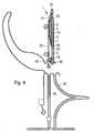
- FIG. 1shows a schematic representation of an analytical aid according to the invention.
- the analytical aid 1comprises a main body 2 with two partial bodies 4, 5 connected via a hinge-like connection 3.
- the first partial body 4carries a lancet 6, which has a lancet tip 7.
- the second partial body 5carries a test element 8 which contains a test field (not shown).
- a (not shown) means for sample transport in the form of a capillaryis used to transport a sample liquid from the sample receiving location 9 to the test field of the test element 8.
- the sample receiving 9is disposed in the region of one of the schamierartigen connection 3 opposite end 11 of the second part body 5.
- FIG. 1shows the analytical tool in the unused state.
- the two partial bodies 4, 5are therefore arranged in a common plane.
- the lancet 6is protected by a seal 10.
- the seal 10is firmly connected to the first part of body 4. It encloses the entire lancet 6 and in particular the lancet tip 7, which projects beyond the first part body 4 in the region of the hinge-like connection 3 and is oriented essentially parallel to the second part body 5. In the region of the lancet tip 7, the seal 10, which spans the hinge-like connection 3, is firmly connected to the second part body 5.
- the two part bodies 4, 5are pivotable relative to one another about the hinge-like connection 3 from the plane.
- the seal 10is separated in the region of the lancet tip 7, so that the lancet tip 7 is released for use.
- test element 8comprises means for electrochemical analysis in the form of electrodes 12, electrical conductors 13 and contact pads 14.
- the analytical tool 1includes a recess 15 in the first part body 4 for engaging a (not shown) guide element in an analyzer, through which the analytical aid 1 is introduced during insertion of the lancet 6 and during sample collection at a sampling point (for example on a finger-ridge of a patient).
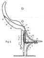
- FIG. 2schematically shows the operation of an analytical aid according to the invention, in particular during insertion of the lancet and during sample taking.
- An inventive analytical tool 1is in FIG. 2 shown laterally in section. It comprises two partial bodies 4, 5, which are connected via a hinge-like connection 3 to a base body 2, wherein the first partial body 4 has a recess 15 for guiding the analytical aid 1.
- a lancet 6 attached to the first part of the body 4is in the unused state ( FIG. 2 (a) ) protected by a pocket-like seal 10.
- a test element 8 arranged on the second partial body 5comprises a test field 17 which is connected to the sample receiving location 9 via a capillary gap serving as a means for sample transport 18 is.
- the dashed linerepresents the skin level 20.
- FIG. 2the possible course of a measurement, for example described by blood glucose.
- an inventive analytical aidis shown in the unused state.
- the two part-bodies 4, 5are in one plane and the lancet 6 is protected by the seal.
- the strip-shaped analytical aid 1is inserted as a single strip or in a magazine together with a multiplicity of strips into a suitable measuring device (not shown). For example, the device is pressed with a cone against a user's finger, turning on the device and allowing the process to proceed without further user interaction.
- An inventive analytical tool 1is released from a magazine and transported in the direction of fingers. If, instead of a magazine, a single-use analytical aid 1 is used, then the motion sequence is comparable.
- FIG. 2 (b)is the pivoting of the two part body 4, 5 shown against each other to the hinge-like compound.
- the strip-shaped analytical aid 1is bent.
- the kinkingtakes place in that the analytical aid 1 is bent either during transport in the device, by a folding movement of a device closure cap or by another force acting on the kink.
- the lancet tip 7cuts through the serving as a seal 10 sterile protective cover.
- the lancet tip 7protrudes beyond the strip contour.
- a fast forward / backward movement of the strip in the direction of arrow 19the lancet tip 7 is stung from an opening (not shown) of the device in the skin of the applied finger.
- This rapid movementcan be done by a spring mechanism, by a magnetic actuator or by a motor drive, possibly in conjunction with a flywheel.
- the stripis withdrawn after the piercing so far in the device, so that it is present again in the unfolded state.
- FIG. 2 (d)the sample holder is shown.
- the path in the devicefor example, changed over a switch, so that the strip emerges unscrupulous with renewed pushing out with the opening of the capillary 18 from the device.
- the absorbent sample receiving sitemeets exactly on a now leaked blood from the skin drop.
- the contact pads on the stripare contacted by the measuring electronics (not shown). This is done by sliding contacts or Aufsetzignee.
- the reflection measurementstarts.
- the stripcan be pulled back into the device. This prevents disturbance of the measurement by movements. The user may receive an audible signal that he can remove the device from his finger.
- the measurement of an optical change, an electrical current or an electrical potentialis comparable to the measurement in conventional test strips.
- the used analytical aid 1can be ejected or withdrawn into a magazine.
- the sample receiving locationcan be arranged, for example, on the end of the second part body facing away from the hinge-like connection or on a longitudinal side of the second part body.
- step C)the lancet tip 7 emerges from an opening 39 (see, eg, below, Fig. 6 ) of the analyzer from and in step E), the sample receiving location 9 exits from the same opening 39.
- step D) of the method according to the inventionthe two partial bodies 4, 5 are preferably pivoted so that they are (as in the unused state) in a common plane (unbent strips). In this sample receiving position, which may correspond to the initial position, the sample is taken at the sample receiving location on the analytical aid 1 according to the invention.
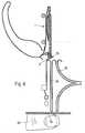
- FIG. 3schematically shows another mode of operation of an analytical aid according to the invention, in particular during insertion of the lancet tip and during sample taking.
- inventive analytical tool 1corresponds in its construction to the in FIG. 2 illustrated analytical tools.
- FIG. 3 (a)is the analytical tool 1 in an initial position in an analyzer, in which the two part-bodies 4, 5 are arranged in a plane.
- the seal 10is intact.
- a slide 21 belonging to the analyzeris arranged above the hinge-like connection 3.
- FIG. 3 (b)shows the pivoting of the two part bodies 4, 5 against each other from the initial position.
- the slider 21exerts a force from above on the base body 2 of the analytical tool 1 in the region of the hinge-like compound 3.
- the two partial bodies 4, 5are at a certain distance from the hinge-like compound 3, each on a deflector 22, 23.
- the strip-shaped analytical aid 1bends at the hinge-like connection.
- the seal 10is separated and the lancet tip 7 is released protruding beyond the first part body 4.
- FIG. 3 (c)the puncture of the lancet tip 7 is shown in a finger 24 of a patient.
- the slider 21has a projection 25 which engages in this position in the recess 15 in the first part body 4.
- the slider 21is used for puncturing the lancet tip 7 in the finger 24 and in the subsequent steps as a guide element 26, through which the analytical tool 1 is introduced during insertion of the lancet 6 and the sample receiving the sampling point 27.
- the puncture into the sampling point 27 on the finger 24takes place in the direction of movement 19.
- FIG. 3 (d)shows the retraction of the analytical tool 1 after the puncture. It is withdrawn until a further deflector 28 is pushed between the two folded body parts 4, 5, and this pivots apart again. In this case, the first part of the body 4 remains connected via the engagement of the projection 25 in the recess 15 with the slider 21.
- FIG. 3 (e)the part bodies 4, 5 are pivoted into a sample receiving position, in which the part bodies 4, 5 in a plane and the analytical aid 1 perpendicular to the in FIG. 3 (a) located in the initial position shown.
- FIG. 3 (f)shows the sample intake.
- the sample receiving location 9 on the test element 8is moved up to the sampling point 27 on the finger 24, at which a drop of blood 29 has formed.
- the bloodis taken up at the sample receiving site 9 and transported by means of the capillary 18 to the test field 17, where the sample, as above to FIG. 2 described, is analyzed.
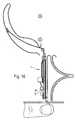
- FIGS. 4 to 11schematically a movement of an analytical aid according to the invention is shown in an analyzer.
- the analytical aid according to the inventionis shown in section.
- the structure of the analytical tool 1largely corresponds to the structure of the relative Figures 2 and 3 described analytical aids 1, with the difference that it additionally has a cover 30 which is arranged on the analytical aid 1.
- the cover 30is firmly connected at its one end 31 to the first part body 4. With the second part of the body 5, the cover 30 via a detention zone 32 is releasably connected and connected again.
- the cover 30protects against unintentional injuries by the lancet 6, in particular after the use of the analytical aid 1.
- the analytical aid 1is shown in its initial position in a schematically illustrated analyzer.
- the strip-shaped analytical device 1is manually inserted into the device, for example, through a slot.
- the opening of the slotis significantly larger than the strip cross section and narrows to a cross section, the analytical tool 1 can still pass without significant friction. This ensures easy handling and the user has no difficulty in hitting the opening.
- large, unambiguous markingscan be printed on the upper side of the analytical aid 1.
- the analyzermay be fitted with appropriate optical or mechanical or other sensors which, if misdirected, will trigger a warning signal or block the insertion of the strip.
- the stripis led straight over a short distance (for example, 5 mm).
- the analytical tool 1In the starting position according to FIG. 4 is the analytical tool 1 in a holder 33 in used in the analyzer.
- the holder 33comprises a projection 25 which engages in the recess 15.
- the holder 33has a driver 34, which can cooperate with guide rails 35, 36 in the analysis device.
- the holder 33is also bendable in the region in which the inserted analytical aid 1 has the hinge-like compound 3.
- the two sub-bodies 4, 5 of the analytical tool 1are arranged in a common plane, and the cover 30 completely covers the analytical tool 1 on one side.
- FIG. 5shows the movement of the analytical tool 1 from the initial position towards the sampling point.
- the lancet 6has separated the seal 10 by means of the lancet tip 7 and the lancet tip 7 protrudes beyond the first part body 4.
- the cover 30is led away laterally via a guide element 37 from the base body 2 into a separate channel 38.
- the cover 30, together with the adhesive zone 32is detached from the analytical aid 1, so that it is connected to the first part body 4 only at the end 31.
- the cover 30can be guided so that it unfolds a spring effect, which presses the main body 2 of the analytical device 1 against an existing in the analyzer stop or ejects the analytical tool 1 after completion of the measuring operation.
- FIG. 6shows the puncture of the lancet tip 7 in a finger 24.
- the driver 34still further in the first guide rail 35 and takes the holder 33 together with analytical tool 1, so that the two part body 4, 5 up to an angle of about 140 ° are pivoted from the initial position.
- the lancet tip 7exits the opening 39 from the analyzer and perforates the skin of the finger 24.
- the analytical device 1is withdrawn after the puncture until the two part of body 4, 5 are again in a common plane and the holder 33 is present without an ankle. During this time, a blood drop 29 forms on the finger 24.
- FIGS. 8 and 9show how the analytical aid 1 according to the invention for sample collection is moved in the analyzer.
- the driver 34is moved out of the first guide rail 35.
- the analytical tool 1is laterally in the analyzer (for example by means of a switch) in a new in FIG. 8 moved position shown.
- the sample receiving location 9is moved toward the finger 24, wherein the driver 34 is guided in the second guide rail 36.
- sample takingFIG. 9
- the blood sample in the capillary-shaped sample transport means 18rises until it reaches the test field 17.
- the cover 30is folded away from the analytical tool 1 and positioned in the channel 38.
- FIG. 10shows the analytical aid 1 according to the invention in a measuring position.
- the analytical aid 1is withdrawn after the sample has been picked up, until an electrical contact 40 is seated on the test pad 8 on the contact pads (not shown) provided therefor. In this position, a measurement is performed.
- the analytical tool 1is moved back to the initial position as shown in FIG. 11 is shown.
- the cover 30is attached by means of the adhesive zone 32 to the second part body 5, so that a user is protected against accidental contact of the lancet 6 and against contamination with sample residues on the used analytical aid 1.
Landscapes
- Health & Medical Sciences (AREA)
- Life Sciences & Earth Sciences (AREA)
- Molecular Biology (AREA)
- General Health & Medical Sciences (AREA)
- Biophysics (AREA)
- Pathology (AREA)
- Engineering & Computer Science (AREA)
- Biomedical Technology (AREA)
- Heart & Thoracic Surgery (AREA)
- Medical Informatics (AREA)
- Hematology (AREA)
- Surgery (AREA)
- Animal Behavior & Ethology (AREA)
- Physics & Mathematics (AREA)
- Public Health (AREA)
- Veterinary Medicine (AREA)
- Dermatology (AREA)
- Measurement Of The Respiration, Hearing Ability, Form, And Blood Characteristics Of Living Organisms (AREA)
- Investigating Or Analysing Biological Materials (AREA)
- Surgical Instruments (AREA)
- Measuring Pulse, Heart Rate, Blood Pressure Or Blood Flow (AREA)
- Magnetic Heads (AREA)
- Sampling And Sample Adjustment (AREA)
Abstract
Description
Translated fromGermanDie Erfindung betrifft ein analytisches Hilfsmittel, das eine Lanzette und ein Testelement enthält, ein Verfahren zur Herstellung eines solchen analytischen Hilfsmittels und ein Verfahren zur Analyse einer Probe mit Hilfe eines solchen analytischen Hilfsmittels.The invention relates to an analytical device containing a lancet and a test element, a method for producing such an analytical device and a method for analyzing a sample by means of such an analytical device.
Die Untersuchung von Blutproben oder von interstitieller Flüssigkeit ermöglichen in der klinischen Diagnostik das frühzeitige und zuverlässige Erkennen von pathologischen Zuständen sowie die gezielte und fundierte Kontrolle von Körperzuständen. Die medizinische Diagnostik setzt stets die Gewinnung einer Probe aus Blut oder interstitieller Flüssigkeit des zu untersuchenden Individuums voraus.The examination of blood samples or of interstitial fluid in the clinical diagnosis allow the early and reliable detection of pathological conditions as well as the targeted and well-founded control of body conditions. Medical diagnosis always requires obtaining a sample of blood or interstitial fluid of the individual to be examined.
Zur Gewinnung der Probe kann die Haut zum Beispiel an der Fingerbeere oder dem Ohrläppchen der zu untersuchenden Person mit Hilfe einer sterilen, scharfen Lanzette perforiert werden, um so eine geringe Menge Blut oder interstitielle Flüssigkeit für die Analyse zu gewinnen. Insbesondere eignet sich diese Methode für die Analyse einer Probe, die unmittelbar nach der Probengewinnung durchgeführt wird.To obtain the sample, the skin may be perforated, for example, on the fingertip or earlobe of the subject to be examined using a sterile, sharp lancet to obtain a small amount of blood or interstitial fluid for analysis. In particular, this method is suitable for the analysis of a sample, which is carried out immediately after the sample extraction.
Vor allem im Bereich des sogenannten "home-monitoring", also dort, wo medizinische Laien selbst einfache Analysen des Bluts oder der interstitiellen Flüssigkeit durchführen, und dort insbesondere für die regelmäßige, mehrmals täglich durchzuführende Blutgewinnung durch Diabetiker für die Kontrolle der Blutglukosekonzentration, werden Lanzetten und dazu passende Geräte (sogenannte Stechhilfen) angeboten, die eine möglichst schmerzarme und reproduzierbare Probengewinnung ermöglichen. Solche Lanzetten und Geräte (Stechhilfen) sind zum Beispiel Gegenstand von
Die eigenhändige Blutzuckerbestimmung ist heute eine weltweit verbreitete Methode in der Diabetes-Kontrolle. Blutzuckergeräte im Stand der Technik bestehen aus einem Analysegerät, in das ein Testelement (Teststreifen) eingeführt wird. Das Testelement wird mit einem Tropfen einer Probe in Kontakt gebracht, der zuvor mittels einer Stechhilfe zum Beispiel aus der Fingerbeere gewonnen wurde. Analytische Testelemente dieser Art sind beispielsweise aus der
Die zahlreichen, für die eigenhändige Blutzuckerbestimmung benötigten Systemkomponenten (Lanzette, Stechhilfe, Testelement und Analysegerät) benötigen viel Platz und bedingen eine relativ komplexe Handhabung. Inzwischen gibt es auch Systeme mit einem höheren Grad der Integration und damit einer einfacheren Handhabung, bei denen zum Beispiel die Testelemente im Analysegerät magaziniert und für die Messung zur Verfügung gestellt werden. Ein nächster Schritt der Miniaturisierung ist beispielsweise durch die Integration von mehreren Funktionen beziehungsweise Funktionselementen in einem einzigen analytischen Hilfsmittel (disposable) zu erreichen. Durch geeignete Kombination von Stechvorgang und sensorischer Analytkonzentrationserfassung auf einem Testelement lässt sich beispielsweise der Bedienablauf deutlich vereinfachen.The numerous system components (lancet, lancing device, test element and analyzer) required for one-handed blood glucose determination require a lot of space and require relatively complex handling. Meanwhile, there are also systems with a higher degree of integration and thus a simpler handling in which, for example, the test elements are stored in the analyzer and provided for the measurement. A next step in miniaturization can be achieved, for example, by integrating several functions or functional elements in a single analytical tool (disposable). By a suitable combination of lancing process and sensory analyte concentration detection on a test element, for example, the operating procedure can be significantly simplified.
Diese im Stand der Technik bekannten analytischen Hilfsmittel sind kompliziert aufgebaut, großteils voluminös, unpraktisch in der Anwendung und kostspielig in der Produktion. Die Herstellung von analytischen Hilfsmitteln birgt eine Vielzahl zu lösender Probleme. Die Lanzette ist zu sterilisieren und die Lanzettensterilität für den Zeitraum der Aufbrauchfrist des analytischen Hilfsmittels sicherzustellen. Die in dem Testfeld des Testelements vorhandene Testchemie kann durch die bekannten Verfahren zur Sterilisierung nachteilig in ihrer Funktions- und Wirkungsweise beeinflusst werden. Es können empfmdliche chemische oder biologische Substanzen geschädigt werden. Die Testchemie sollte daher möglichst nicht dem Sterilisierungsverfahren für die Lanzette ausgesetzt werden. Für den Gebrauch des analytischen Hilfsmittels muss der Sterilschutz außerdem sicher, ohne Verletzungsgefahr für den Benutzer, entfernbar sein.These known in the art analytical tools are complicated, largely bulky, unpractical in use and costly in production. The production of analytical aids involves a large number of problems to be solved. The lancet should be sterilized and lancet sterility ensured for the period of use of the analytical device. The test chemistry present in the test field of the test element can be adversely affected in its function and effect by the known methods for sterilization. It can damage sensitive chemical or biological substances. The test chemistry should therefore not be exposed to the sterilization procedure for the lancet. For the use of the analytical tool, the sterile guard must also be safely removable, without risk of injury to the user.
Die Aufgabe der vorliegenden Erfindung war es, die Nachteile des Standes der Technik zu vermeiden und die genannten Probleme zu lösen.The object of the present invention was to avoid the disadvantages of the prior art and to solve the problems mentioned.
Diese Aufgabe wird erfindungsgemäß gelöst durch ein analytisches Hilfsmittel gemäß Anspruch 1.This object is achieved by an analytical aid according to
Bei diesem analytischen Hilfsmittel (oder synonym dazu "disposable") werden die drei Funktionen Einstechen, Probenaufnahme und Bereitstellen einer Testchemie zur Analyse der Probe zusammengefasst.This analytical tool (or "disposable") summarizes the three functions of piercing, sampling, and providing a test chemistry to analyze the sample.
Der Grundkörper des analytischen Hilfsmittels dient als Träger für die Lanzette. Er umfasst zwei Teilkörper und ist vorzugsweise streifenförmig ausgebildet, wenn sich die zwei Teilkörper in einer Ebene befinden, also nicht gegeneinander verschwenkt sind. Als Abmessungen eines solchen streifenförmigen analytischen Hilfsmittels können beispielsweise eine Länge von ca. 38 mm und eine Breite von ca. 9 mm gewählt werden. An dem den Probenaufnahmeort aufweisenden Ende des zweiten Teilkörpers können die Ecken in einem 45°-Winkel um ca. 2 mm abgeschnitten werden. Eine gegebenenfalls vorhandene Abdeckung kann über diese abgeschnittenen Ecken hinausragen, so dass sie leicht greifbar ist.The main body of the analytical device serves as a carrier for the lancet. It comprises two partial bodies and is preferably designed in the shape of a strip when the two partial bodies are in one plane, that is, they are not pivoted relative to one another. When Dimensions of such a strip-shaped analytical aid, for example, a length of about 38 mm and a width of about 9 mm can be selected. At the end of the second part body having the specimen receiving location, the corners can be cut off at a 45 ° angle by about 2 mm. An optional cover can protrude beyond these cut corners, so that it is easily accessible.
Die Lanzette ist zum Perforieren der Haut eines Patienten an passenden Stellen mit der Lanzettenspitze zur Gewinnung einer Blutprobe oder einer Probe aus interstitieller Flüssigkeit vorgesehen. Als Lanzette kann eine runde, nadelförmige oder flache Lanzette dienen. Runde, nadelförmige Lanzetten werden üblicherweise aus Drahtabschnitten gefertigt, die durch Schleifen mit einer scharfen Spitze versehen sind. Flache Lanzetten werden üblicherweise durch Stanzen, Ätzen oder Laserschneiden aus Flachstahl gefertigt. Die Lanzette ist bei dem erfindungsgemäßen analytischen Hilfsmittel auf dem ersten Teilkörper befestigt. Die Lanzettenspitze ragt über den Rand des ersten Teilkörpers mindestens um die zur Perforation der Haut notwendige Einstechtiefe hinaus. Die Befestigung der Lanzette auf dem ersten Teilkörper erfolgt vorzugsweise durch Kleben, insbesondere mit Hilfe von Schmelzkleber oder durch Einschweißen oder -schmelzen. Der erste Teilkörper kann so vorstrukturiert sein, dass er Ausnehmungen zum Aufnehmen der Lanzette aufweist. Eine solche Struktur kann zum Beispiel durch Prägen oder durch Aufkleben einer Folie mit entsprechenden Ausnehmungen erzeugt werden.The lancet is designed to perforate a patient's skin at appropriate locations with the lancet tip for obtaining a blood sample or a sample of interstitial fluid. The lancet can be a round, needle-shaped or flat lancet. Round, needle-shaped lancets are usually made of wire sections that are provided by grinding with a sharp point. Flat lancets are usually made by punching, etching or laser cutting of flat steel. The lancet is attached to the analytical device according to the invention on the first part of the body. The lancet tip protrudes beyond the edge of the first part body at least around the piercing depth necessary for the perforation of the skin. The attachment of the lancet on the first part body is preferably carried out by gluing, in particular by means of hot melt adhesive or by welding or melting. The first part body may be pre-structured so as to have recesses for receiving the lancet. Such a structure can be produced for example by embossing or by gluing a film with corresponding recesses.
Die auf dem ersten Teilkörper fixierte Lanzette, zumindest die Lanzettenspitze, ist durch eine Versiegelung geschützt, so lange sich das analytische Hilfsmittel in einem unbenutzten Zustand befindet. Durch die Versiegelung kann zumindest die Lanzettenspitze im unbenutzten Zustand bis unmittelbar vor der Benutzung steril (keimfrei) gehalten werden. Ferner erlaubt die Versiegelung keine Kontamination der Lanzettenspitze mit Bestandteilen der in dem Testfeld des Testelements enthaltenen Testchemie, da die Versiegelung die Lanzette vollständig von dem Testfeld trennt.The lancet fixed on the first part-body, at least the lancet tip, is protected by a seal as long as the analytical aid is in an unused state. Due to the seal, at least the lancet tip in the unused state can be kept sterile (germ-free) until immediately before use. Further, the seal does not permit contamination of the lancet tip with constituents of the test chemistry contained in the test field of the test element, since the seal completely separates the lancet from the test field.
Das Testelement dient der Analyse der Blutprobe beziehungsweise der Probe aus interstitieller Flüssigkeit. Es enthält mindestens ein Testfeld mit einer Testchemie, die auf die zu untersuchende Probe abgestimmt ist. Das Testelement ist auf dem zweiten Teilkörper des erfindungsgemäßen analytischen Hilfsmittels angeordnet. Das Testelement beziehungsweise der zweite Teilkörper kann ferner ein Mittel zum Probentransport von einem Probenaufnahmeort, der zur Aufnahme der Probe von der mit der Lanzette perforierten Haut dient, zu dem Testfeld, auf dem die Analyse der Probe durchgeführt wird, tragen.The test element is used to analyze the blood sample or sample of interstitial fluid. It contains at least one test field with a test chemistry that is tailored to the sample to be examined. The test element is arranged on the second part body of the analytical aid according to the invention. The test element or the second part of the body may further comprise a means for sample transport from a sample receiving location, which is for receiving the sample of the lancet perforated skin, to the test field on which the analysis of the sample is performed wear.
Die zwei Teilkörper sind über eine scharnierartige Verbindung miteinander verbunden. Die schamierartige Verbindung ermöglicht ein Verschwenken der beiden Teilkörper gegeneinander. Im unbenutzten Zustand des erfindungsgemäßen analytischen Hilfsmittels liegen die beiden Teilkörper im Wesentlichen in einer gemeinsamen Ebene. In dieser im Folgenden als Anfangsposition bezeichneten Anordnung bilden die zwei Teilkörper einen im Wesentlichen ebenen Grundkörper und sind nicht gegeneinander verschwenkt (α = 0°). Die Lanzette liegt dann an dem ebenen Grundkörper an und ist durch die Versiegelung geschützt, so dass eine unerwünschte Verletzung durch die Lanzettenspitze vermieden wird. Bei der Verwendung des erfindungsgemäßen analytischen Hilfsmittels werden die beiden Teilkörper gegeneinander verschwenkt, wodurch u.a. die Lanzettenspitze zur Benutzung freigegeben werden kann. Beim Verschwenken der Teilkörper wird in diesem Fall die Versiegelung aufgetrennt. Das Auftrennen der Versiegelung erfolgt dabei zum Beispiel durch Zerreißen aufgrund einer beim Verschwenken der Teilkörper auf die Versiegelung wirkenden Zugkraft oder durch Zerschneiden der Versiegelung durch die Lanzettenspitze. Eine weitere Möglichkeit ist, dass die Versiegelung beim Verschwenken der Teilkörper an ihrer Verbindungsstelle mit den Teilkörpern (z.B. Klebeverbindung) abgetrennt wird und so die Lanzettenspitze freigegeben wird. Die Versiegelung kann aber auch beim Einsetzen des analytischen Hilfsmittels in ein Analysegerät durch eine dafür vorgesehene Einrichtung (z.B. Klinge) oder vor dem Einsetzen in das Analysegerät durch den Benutzer geöffnet werden.The two part bodies are connected to each other via a hinge-like connection. The schamierartige connection allows pivoting of the two body parts against each other. In the unused state of the analytical aid according to the invention, the two partial bodies lie substantially in a common plane. In this arrangement, referred to below as the initial position, the two partial bodies form a substantially flat main body and are not pivoted relative to one another (α = 0 °). The lancet then rests on the planar base body and is protected by the seal, so that an undesirable injury is avoided by the lancet tip. When using the analytical aid according to the invention, the two partial bodies are pivoted against each other, whereby u.a. the lancet tip can be released for use. When pivoting the part body in this case, the seal is separated. The separation of the seal is carried out, for example, by tearing due to a tensile force acting on the seal during pivoting of the part body or by cutting the seal by the lancet tip. Another possibility is that the seal is separated during pivoting of the part body at its junction with the partial bodies (for example, adhesive connection) and thus the lancet tip is released. However, the seal may also be opened upon insertion of the analytical device into an analyzer by a dedicated device (e.g., blade) or prior to insertion into the analyzer by the user.
Die schamierartige Verbindung ist bei der vorliegenden Erfindung vorzugsweise so ausgebildet, dass die Teilkörper um einen Winkel α von mindestens 90° und bis zu 180° aus der Anfangsposition gegeneinander verschwenkt werden können. Bei einem Verschwenken um α = 180° aus der Anfangsposition sind die zwei Teilkörper zusammengeklappt, also nebeneinander und parallel zueinander angeordnet und an der schamierartigen Verbindung miteinander verbunden.The hinge-like compound is preferably formed in the present invention so that the part body can be pivoted by an angle α of at least 90 ° and up to 180 ° from the initial position against each other. When pivoting about α = 180 ° from the initial position, the two body parts are folded, so arranged side by side and parallel to each other and connected to the hinge-like compound.
Sobald die beiden Teilkörper gegeneinander verschwenkt sind und die Lanzettenspitze freigegeben ist, kann die Lanzettenspitze zur Perforation der Haut (zum Beispiel der Fingerbeere) eines Patienten dienen, um eine Probe aus Blut oder interstitieller Flüssigkeit zu gewinnen. Anschließend können die Teilkörper des analytischen Hilfsmittels wieder in die Anfangsposition zurückgeschwenkt werden, so dass die Lanzette erneut an dem Grundkörper anliegt und eine Verletzungsgefahr weitgehend ausgeschlossen ist. Zur Aufnahme der Probe kann dann der Probenaufnahmeort des analytischen Hilfsmittels an die Probe (zum Beispiel einen Blutstropfen) herangeführt werden, um diese auf das Testelement aufzunehmen, ggf. mit Hilfe des Mittels zum Probentransport zum Testfeld zu transportieren, wo sie mit der Testchemie reagiert, und sie dort zu analysieren.Once the two partial bodies are pivoted against each other and the lancet tip is released, the lancet tip can be used to perforate the skin (for example, the fingertip) of a patient to obtain a sample of blood or interstitial fluid. Subsequently, the partial body of the analytical aid can be pivoted back into the initial position, so that the lancet rests again on the base body and a risk of injury is largely excluded. to Recording the sample can then be brought to the sample receiving site of the analytical tool to the sample (for example, a drop of blood) to include them on the test element, possibly with the aid of the means for transporting samples to the test field, where it reacts with the test chemistry, and to analyze them there.
Die vorliegende Erfindung weist u.a. folgende Vorteile auf:
- Das erfindungsgemäße analytische Hilfsmittel weist einen einfachen und kompakten Aufbau mit einer geringen Anzahl an Komponenten auf und kombiniert eine Vielzahl von Funktionen. Es ist für den Einsatz in kompakten automatisierten Analysegeräten geeignet.
- Die Lanzette ist durch die Versiegelung keimdicht verschlossen, so dass Keime bis unmittelbar vor der Benutzung der Lanzette nicht an die Lanzettenspitze gelangen können. Sie ist durch die Versiegelung auch vor Kontakt mit der Testchemie geschützt.
- Die zwei Teilkörper, von denen der eine die Lanzette und der andere das Testelement trägt, können getrennt voneinander vorkonfektioniert werden. Das Sterilisieren der Lanzette kann daher vor dem Verbinden der zwei Teilkörper mit der schamierartigen Verbindung erfolgen (zum Beispiel durch γ-Bestrahlung), so dass die Testchemie nicht der gegebenenfalls schädlichen Sterilisierung ausgesetzt wird.
- Das erfindungsgemäße analytische Hilfsmittel kann eine ähnliche Form wie handelsübliche Teststreifen aufweisen, so dass es in einem an den Aufbau und die Funktionsweise des analytischen Hilfsmittels angepassten handelsüblichen Analysegerät eingesetzt werden kann.
- Der Benutzer des erfindungsgemäßen analytischen Hilfsmittels ist vor einer unbeabsichtigten Verletzung an der Lanzettenspitze weitgehend geschützt. Das analytische Hilfsmittel ermöglicht eine hohe Einstichgeschwindigkeit der Lanzettenspitze und eine kurze Verweilzeit der Lanzettenspitze in der Haut, so dass das Einstechen schmerzarm ist.
- The analytical aid according to the invention has a simple and compact construction with a small number of components and combines a multiplicity of functions. It is suitable for use in compact automated analyzers.
- The lancet is sealed germ-tight by the seal so that germs can not reach the lancet tip until just before using the lancet. It is also protected from contact with the test chemistry by the sealant.
- The two partial bodies, one of which carries the lancet and the other the test element, can be prefabricated separately from each other. Sterilization of the lancet may therefore be performed prior to joining the two partial bodies to the hinge-like compound (for example, by γ-irradiation), so that the test chemistry is not exposed to the optionally harmful sterilization.
- The analytical aid according to the invention may have a similar form to commercially available test strips, so that it can be used in a commercial analyzer adapted to the design and operation of the analytical device.
- The user of the analytical aid according to the invention is largely protected against unintentional injury to the lancet tip. The analytical tool allows a high puncture speed of the lancet tip and a short residence time of the lancet tip in the skin, so that the piercing is painless.
Gemäß einer bevorzugten Ausführungsform der vorliegenden Erfindung ist die schamierartige Verbindung ein flexibler Streifen, der die zwei Teilkörper miteinander verbindet. Der flexible Streifen kann gegen die in einer Ebene mit ihren Kanten aneinander liegenden Teilkörper geklebt oder geschweißt werden. Er kann zum Beispiel aus einem Klebeband bestehen. Die schamierartige Verbindung kann auch allein durch die Versiegelung gebildet werden. Eine weitere Möglichkeit ist die Ausführung der scharnierartigen Verbindung als Filmscharnier. Filmscharniere oder Filmgelenke sind Bandscharniere und haben keine mechanischen Teile. Ein Filmscharnier ist eine flexible, dünnwandige Gelenkrille zwischen zwei zu verbindenden Teilen.According to a preferred embodiment of the present invention, the hinge-like compound is a flexible strip which connects the two body parts together. The flexible strip can be glued or welded against the abutting in a plane with their edges part body. For example, it can consist of an adhesive tape. The schamierartige connection can also alone by the Seal are formed. Another possibility is the execution of the hinge-like connection as a film hinge. Film hinges or film hinges are hinge hinges and have no mechanical parts. A film hinge is a flexible, thin-walled hinge groove between two parts to be joined.
Der Probenaufnahmeort ist vorzugsweise im Bereich eines der scharnierartigen Verbindung entgegengesetzten Endes des zweiten Teilkörpers angeordnet. Dadurch befindet sich der Probenaufnahmeort an einem exponierten und damit gut erreichbaren Ende des Grundkörpers, wenn die Teilkörper nicht gegeneinander verschwenkt sind und somit in einer Ebene liegen.The sample receiving location is preferably arranged in the region of one of the hinge-like connection opposite end of the second body part. As a result, the sample receiving location is located on an exposed and therefore easily accessible end of the base body, when the partial bodies are not pivoted against each other and thus lie in one plane.
Die Lanzettenspitze ragt vorzugsweise im Bereich der schamierartigen Verbindung über den ersten Teilkörper hinaus. Dadurch liegt sie an dem Grundkörper beziehungsweise an dem zweiten Teilkörper an, wenn sich das erfindungsgemäße analytische Hilfsmittel in der Anfangsposition befindet und ragt gut zugänglich und stechbereit über die Kante des ersten Teilkörpers hinaus, sobald die Teilkörper um die schamierartige Verbindung um einen Winkel α ≥ 90° gegeneinander aus der Anfangsposition verschwenkt sind. Vorzugsweise ist die Lanzettenspitze daher im unbenutzten Zustand des analytischen Hilfsmittels im Wesentlichen parallel zu dem zweiten Teilkörper ausgerichtet.The lancet tip preferably projects beyond the first part body in the region of the hinge-like connection. As a result, it rests on the base body or on the second part body when the analytical aid according to the invention is in the initial position and protrudes readily accessible and ready to pierce beyond the edge of the first part body, as soon as the part bodies around the hinge-like compound by an angle α ≥ 90th ° are pivoted against each other from the initial position. Preferably, the lancet tip is therefore aligned in the unused state of the analytical aid substantially parallel to the second part body.
Gemäß einer bevorzugten Ausführungsform der vorliegenden Erfindung ist die Versiegelung ein taschenartiger Schutz, der die Lanzette im unbenutzten Zustand des analytischen Hilfsmittels teilweise oder vollständig umschließt. Im Falle eines nur teilweisen Umschließens ist zumindest die Lanzettenspitze durch den taschenartigen Schutz steril verschlossen. Der taschenartige Schutz wird zum Beispiel durch eine dünne Folie gebildet, die die Lanzette und insbesondere die Lanzettenspitze einhüllt, wobei die Folie längs der Lanzette zu einer Art Tasche verbunden ist. Die Folie wird dabei zum Beispiel vor der Montage der Lanzette auf dem ersten Teilkörper teilweise aufgesiegelt und nach der Montage der Lanzette über die Lanzettenspitze gefaltet und zum Beispiel mit Klebstoff am aufgesiegelten Teil der Folie so befestigt, dass sich die Lanzettenspitze in einem aus der Folie gebildeten taschenartigen Schutz befindet. Bevorzugt wird die Lanzette bei der Montage um ihre Längsachse so gedreht, dass eine Kante des Lanzettenschliffs möglichst senkrecht zur schamierartigen Verbindung orientiert ist und von ihr weg weist.According to a preferred embodiment of the present invention, the seal is a bag-like protector which partially or completely encloses the lancet in the unused state of the analytical device. In the case of only partial enclosing at least the lancet tip is sterile closed by the bag-like protection. The pocket-like protector is formed, for example, by a thin film which wraps around the lancet and in particular the lancet tip, the film being connected along the lancet to form a kind of pocket. The film is partially sealed, for example, before the assembly of the lancet on the first part body and folded after the assembly of the lancet on the lancet tip and fixed for example with adhesive on the sealed part of the film so that the lancet tip formed in one of the film pocket-like protection is located. Preferably, the lancet is rotated during assembly about its longitudinal axis so that an edge of the lancet is oriented as perpendicular as possible to the hinge-like compound and points away from it.
Vorzugsweise ist die Versiegelung bei der Lanzettenspitze fest mit dem zweiten Teilkörper verbunden. Im Falle eines taschenartigen Schutzes kann dieser zum Beispiel an seiner Vorderkante bei der Lanzettenspitze mit dem zweiten Teilkörper verbunden sein. Somit überspannt die Versiegelung, die sowohl an dem ersten Teilkörper befestigt ist, als auch im Bereich der Lanzettenspitze mit dem zweiten Teilkörper verbunden ist, die scharnierartige Verbindung zwischen den beiden Teilkörpern. Sie ist vorzugsweise in der Anfangsposition vollständig ausgestreckt und wird beim Verschwenken der Teilkörper aus der Anfangsposition über die Kanten der Teilkörper bei der scharnierartigen Verbindung gespannt, so dass sie im Bereich der Lanzettenspitze zerreißt und diese zur Benutzung freigibt. Dazu ist die Versiegelung zumindest im Bereich der Lanzettenspitze aus einem spröden Material gefertigt. Spröde bedeutet in diesem Zusammenhang, dass das Material eine kleine Bruchdehnung und geringe Weiterreißfestigkeit aufweist. Ein bevorzugtes Material ist zum Beispiel geschäumtes orientiertes Polypropylen (OPP) der Fa. Huhtamaki Deutschland GmbH&Co. KG in Ronsberg (Allgäu). Durch die Materialwahl und die Orientierung des Lanzettenschliffs wird ein glattes Durchtrennen der Versiegelung erreicht. Weiterhin wird in einer bevorzugten Ausgestaltung der Erfindung die schamierartige Verbindung durch die Versiegelung gebildet.Preferably, the seal at the lancet tip is firmly connected to the second part body. In the case of a pocket-like protection, this can, for example, on his Leading edge at the lancet tip to be connected to the second part of the body. Thus, the seal, which is fastened both to the first part body and in the region of the lancet tip to the second part body, spans the hinge-like connection between the two part bodies. It is preferably fully extended in the initial position and is tensioned during pivoting of the part body from the initial position over the edges of the body part in the hinge-like connection, so that it tears in the area of the lancet tip and releases it for use. For this purpose, the seal is made of a brittle material, at least in the area of the lancet tip. Brittle in this context means that the material has a small elongation at break and low tear strength. A preferred material is, for example, foamed oriented polypropylene (OPP) from Huhtamaki Deutschland GmbH & Co. KG in Ronsberg (Allgäu). The choice of material and the orientation of the lancet cut achieve a smooth cut through of the seal. Furthermore, in a preferred embodiment of the invention, the schamierartige compound is formed by the seal.
Das Testelement umfasst bei der vorliegenden Erfindung vorzugsweise Mittel zur elektrochemischen oder optischen Analyse einer auf dem Testfeld vorhandenen Probe. Die sensorische Erfassung eines Analyten auf einem Testelement mittels photometrischer oder elektrochemischer Verfahren erfolgt gemäß im Stand der Technik bekannter Verfahren. Im Falle, dass ein elektrochemischer Nachweis eines Analyten in der Probe erfolgen soll, ist der zweite Teilkörper mit elektrischen Verbindungen versehen. Diese elektrischen Verbindungen können beispielsweise durch Aufsputtern einer Goldschicht und das Formen von Elektroden, Leiterbahnen und Kontaktpads aus der Goldschicht mittels Laserablation hergestellt werden. Die Elektroden können mit Reagenz- und Abdeckschichten überzogen werden. Im Falle, dass ein optischer Nachweis eines Analyten in der Probe erfolgen soll, ist der zweite Teilkörper mit den notwendigen optischen Elementen ausgestattet, zum Beispiel einem lichtdurchlässigen Fenster.The test element in the present invention preferably comprises means for the electrochemical or optical analysis of a sample present on the test field. The sensory detection of an analyte on a test element by means of photometric or electrochemical methods is carried out according to methods known in the art. In the event that an electrochemical detection of an analyte in the sample is to take place, the second partial body is provided with electrical connections. These electrical connections can be made for example by sputtering a gold layer and the forming of electrodes, tracks and contact pads from the gold layer by means of laser ablation. The electrodes can be coated with reagent and cover layers. In the event that an optical detection of an analyte in the sample is to take place, the second part body is equipped with the necessary optical elements, for example a transparent window.
Gemäß einer Ausführungsform der vorliegenden Erfindung weist das erfindungsgemäße analytische Hilfsmittel eine Ausnehmung in dem ersten Teilkörper zum Eingreifen eines Führungselements in einem Analysegerät auf, durch das das analytische Hilfsmittel beim Einstich der Lanzette und bei der Probenaufnahme an eine Probenentnahmestelle herangeführt wird. Mit Hilfe des in die Ausnehmung eingreifenden Führungselements kann das erfindungsgemäße analytische Hilfsmittel in dem Analysegerät ohne einen manuellen Eingriff des Benutzers in die entsprechende Position geführt werden. Vorzugsweise enthält das erfindungsgemäße analytische Hilfsmittel ferner eine Abdeckung, die auf dem analytischen Hilfsmittel angeordnet ist und die mit dem ersten Teilkörper fest und mit dem zweiten Teilkörper über eine Haftzone lösbar und wiederverbindbar verbunden ist. Die Abdeckung ist vorzugsweise nur an dem der scharnierartigen Verbindung entgegengesetzten Ende des ersten Teilkörpers fest verbunden und liegt auf den beiden Teilkörpern auf, so lange das analytische Hilfsmittel nicht benutzt wird. Die Abdeckung kann während der Benutzung zumindest von dem zweiten Teilkörper und der Lanzettenspitze weggeklappt werden, so dass sie einer Benutzung des analytischen Hilfsmittels nicht im Wege steht und nach der Benutzung wieder den gesamten Grundkörper abdecken, um die Lanzette unzugänglich aufzubewahren. Als Material für die Abdeckung wird vorzugsweise Polyester oder Polycarbonat gewählt. Die Abdeckung hat bevorzugt eine Dicke von 100 bis 150 µm. Sie kann dieselbe Länge wie der Grundkörper besitzen oder länger als der Grundkörper ausgeführt sein, so dass sie über das der schamierartigen Verbindung entgegengesetzte Ende des zweiten Teilkörpers in der Anfangsposition hinausragt. An dem zweiten Teilkörper ist die Abdeckung in der Anfangsposition lösbar mit Hilfe der Haftzone verbunden. Die Haftzone kann zum Beispiel eine leicht lösbare und wiederverbindbare Klebeschicht aufweisen, an der die Abdeckung beziehungsweise der zweite Teilkörper haftet. Die Haftzone kann auf dem zweiten Teilkörper oder auf der Abdeckung angeordnet sein. Durch die Abdeckung kann in vorteilhafter Weise eine unbeabsichtigte Verletzung des Benutzers oder Kontamination durch Probenreste vermieden werden.According to one embodiment of the present invention, the analytical aid according to the invention has a recess in the first part body for engaging a guide element in an analyzer, by means of which the analytical aid is brought to a sampling location when the lancet is pierced and when the sample is picked up. With the aid of the guide element engaging in the recess, the analytical aid according to the invention can be guided in the analyzer without manual intervention by the user into the corresponding position. Preferably, the analytical aid according to the invention further comprises a cover, which is arranged on the analytical aid and which is fixed to the first part of body and the second part of body via an adhesive zone releasably and reconnectably connected. The cover is preferably firmly connected only at the hinge-like connection opposite end of the first body part and rests on the two part bodies, as long as the analytical aid is not used. The cover can be folded away during use at least from the second part of the body and the lancet tip so that it does not interfere with the use of the analytical tool and after use again cover the entire body to keep the lancet inaccessible. As the material for the cover is preferably selected polyester or polycarbonate. The cover preferably has a thickness of 100 to 150 μm. It may have the same length as the main body or be designed longer than the main body so that it protrudes beyond the end of the second part body opposite the hinge-like connection in the initial position. At the second part of the body cover is releasably connected in the initial position by means of the adhesive zone. The adhesive zone can, for example, have an easily detachable and reconnectable adhesive layer to which the cover or the second partial body adheres. The adhesive zone may be arranged on the second partial body or on the cover. The cover advantageously avoids unintentional injury to the user or contamination by sample residues.
Gemäß einer bevorzugten Ausführungsform der vorliegenden Erfindung ist das Mittel zum Probentransport eine Kapillare. Eine Kapillare in Form eines Kapillarspalts kann zum Beispiel durch ein strukturiertes Spacer-Klebeband und eine hydrophile Deckelfolie gebildet werden, die auf dem zweiten Teilkörper befestigt sind. Das Mittel zum Probentransport kann aber auch jedes andere, dem Fachmann bekannte, zum Probentransport geeignete Mittel sein, beispielsweise kapillaraktives Material oder ein Docht. Die Probe kann sich bei dem erfindungsgemäßen analytischen Hilfsmittel jedoch auch ohne ein zusätzlich vorgesehenes Mittel zum Probentransport von dem Probenaufnahmeort auf dem Testfeld verteilen, z.B. falls das Testfeld an den Probenaufnahmeort grenzt und ein saugfähiges Material enthält.According to a preferred embodiment of the present invention, the means for sample transport is a capillary. A capillary in the form of a capillary gap can be formed, for example, by a structured spacer adhesive tape and a hydrophilic cover film, which are fastened on the second part body. However, the means for sample transport can also be any other means known to those skilled in the art for transporting samples, for example capillary-active material or a wick. However, in the case of the analytical aid according to the invention, the sample can also be distributed on the test field without additional means for transporting samples from the sample receiving location, e.g. if the test field is adjacent to the sample receiving site and contains an absorbent material.
Die Erfindung bezieht sich weiterhin auf ein Verfahren zur Herstellung von erfindungsgemäßen analytischen Hilfsmitteln, wobei die ersten Teilkörper aus Abschnitten eines ersten biegsamen Bandes und die zweiten Teilkörper aus Abschnitten eines zweiten biegsamen Bandes gefertigt werden, und die beiden biegsamen Bänder mit Hilfe von Pilotlöchern relativ zueinander ausgerichtet werden, bevor sie miteinander zu Grundkörpern verbunden und die Abschnitte vereinzelt werden. Die biegsamen Bänder müssen einerseits so starr sein, dass ein Verschwenken der daraus gefertigten Teilkörper zum Freisetzen der Lanzettenspitze möglich ist und müssen andererseits so flexibel sein, dass eine Rollenproduktion möglich ist. Geeignete biegsame Bänder sind beispielsweise Polyesterfolien, z. B. die Polyesterfolie "Melinex", Hersteller DuPont Teijin Films, mit einer Dicke von ca. 350 µm, oder ähnliche Polymerfolien. Die zwei biegsamen Bänder können aus einem biegsamen Band durch Zerschneiden hergestellt werden. Die Lanzetten und Versiegelungen werden an dem ersten biegsamen Band befestigt. Das erste biegsame Band wird dann aufgerollt und einer Sterilisierung, insbesondere einer Strahlensterilisation unterworfen. Eine Strahlensterilisation kann zum Beispiel mit einer Dosis von 25 kGray durchgeführt werden. Nachdem die Lanzetten und die Versiegelungen jeweils auf einem Abschnitt des ersten biegsamen Bandes befestigt und sterilisiert wurden und die Testelemente jeweils auf einem Abschnitt des zweiten biegsamen Bandes befestigt wurden, können die beiden biegsamen Bänder miteinander verbunden werden. Dazu müssen sie passgenau miteinander verbunden werden. Die Bänder werden daher unter einer regelbaren Spannung gehalten, die so geregelt wird, dass die in beiden Bändern vorhandenen Pilotlöcher sich immer innerhalb einer zulässigen Toleranz gegenüberliegen, bevor die Bänder miteinander über eine schamierartige Verbindung zum Beispiel durch ein Klebeband zu einem einzigen biegsamen Band verbunden werden. Dann wird die Versiegelung mindestens mit einer Kante an dem zweiten Teilkörper durch Kleben oder Schweißen befestigt. Anschließend werden die einzelnen erfmdungsgemäßen analytischen Hilfsmittel von dem Band abgeschnitten. Der Schnitt zum Vereinzeln der analytischen Hilfsmittel wird mittig zwischen je zwei Lanzetten parallel zu diesen geführt. Vor oder nach dem Vereinzeln der analytischen Hilfsmittel können die Bereiche, die die Pilotlöcher aufweisen, zum Beispiel durch Abschneiden entfernt werden.The invention further relates to a method for the production of analytical aids according to the invention, wherein the first part bodies are made of sections of a first flexible band and the second part bodies of sections of a second flexible band, and the two flexible bands by means of Pilot holes are aligned relative to each other before they are connected together to basic bodies and the sections are separated. On the one hand, the flexible bands must be so rigid that pivoting of the part bodies produced therefrom for releasing the lancet tip is possible and, on the other hand, they must be flexible enough to allow roll production. Suitable flexible bands are for example polyester films, for. As the polyester film "Melinex", manufacturer DuPont Teijin Films, with a thickness of about 350 microns, or similar polymer films. The two flexible bands can be made from a flexible band by cutting. The lancets and seals are attached to the first flexible band. The first flexible band is then rolled up and subjected to sterilization, in particular radiation sterilization. Radiation sterilization may be performed, for example, at a dose of 25 kGray. After each of the lancets and seals has been secured and sterilized on a portion of the first flexible band, and the test elements have each been affixed to a portion of the second flexible band, the two flexible bands can be connected together. For this they must be accurately connected with each other. The tapes are therefore held under a controllable tension which is controlled so that the pilot holes present in both tapes are always within an allowable tolerance before the tapes are joined together via a hinge-like connection, for example by an adhesive tape, into a single flexible tape , Then, the seal is attached at least one edge to the second part body by gluing or welding. Subsequently, the individual inventive analytical aids are cut off from the belt. The section for separating the analytical aids is guided centrally between each two lancets parallel to these. Before or after singulation of the analytical aids, the areas comprising the pilot holes can be removed by, for example, cutting off.
Eine andere Möglichkeit der Herstellung der erfindungsgemäßen analytischen Hilfsmittel aus zwei biegsamen Bändern ist, dass die Abschnitte des ersten biegsamen Bandes mit den versiegelten und sterilisierten Lanzetten und die Abschnitte des zweiten biegsamen Bandes mit den Testelementen zuerst getrennt vereinzelt werden und anschließend jeweils ein Abschnitt der zwei Bänder über schamierartige Verbindungen zu jeweils einem Grundkörper miteinander verbunden werden (gegebenenfalls ebenfalls unter Verwendung jeweils mindestens eines Pilotlochs).Another way of producing the inventive analytical aids from two flexible bands is that the sections of the first flexible band with the sealed and sterilized lancets and the sections of the second flexible band with the test elements are separated first separately and then each a portion of the two bands be connected to each other via a schamierartige compounds in each case a basic body (optionally also using each at least one pilot hole).
Gemäß einer bevorzugten Ausführung der vorliegenden Erfindung wird die Versiegelung jedes einzelnen analytischen Hilfsmittels nach dem Vereinzeln in einem Vakuum auf Dichtigkeit kontrolliert, so dass eine Beschädigung der Versiegelung bei dem Schnitt zum Vereinzeln der analytischen Hilfsmittel erkannt wird. Dazu können die einzelnen analytischen Hilfsmittel in eine Kammer eingebracht werden, die evakuiert wird. Die durch die Versiegelung eingeschlossene Luft bläht die Versiegelung mit abnehmendem Außendruck zunehmend auf. Bei einer beschädigten Versiegelung bläht sich diese nicht oder nur unvollständig auf. Dies kann durch ein automatisches Bildverarbeitungssystem erfasst und ausgewertet werden. Defekte analytische Hilfsmittel werden ausgesondert. Sie können mit Hilfe der Bildauswertung auf die Fehlerursache hin untersucht werden. Dies erlaubt eine schnelle Reaktion auf und Beseitigung der Fehlerursachen.According to a preferred embodiment of the present invention, the sealing of each individual analytical device after singulation in a vacuum Tightness is controlled, so that a damage of the seal in the cut for separating the analytical aids is detected. For this purpose, the individual analytical aids can be introduced into a chamber which is evacuated. The air trapped by the seal increasingly inflates the seal with decreasing external pressure. If the seal is damaged, it will not inflate, or only incompletely. This can be detected and evaluated by an automatic image processing system. Defective analytical tools are discarded. They can be examined for the cause of the error with the aid of the image analysis. This allows a quick reaction to and elimination of the causes of the error.
Die fertigen erfindungsgemäßen analytischen Hilfsmittel können erfindungsgemäß einzeln oder zu mehreren in geeigneten Behältern oder Magazinen verpackt aufbewahrt werden. Als Magazin kann beispielsweise ein System verwendet werden, wie es in der
Vorzugsweise ist das analytische Hilfsmittel eingerichtet, um ein Verfahren zur Analyse einer Probe mit einem mit den folgenden Schritten zu ermöglichen:
- A) Einsetzen eines analytischen Hilfsmittels in ein Analysegerät,
- A1) alternativ oder zusätzlich: Einsetzen eines Magazins in ein Analysegerät; Bereitstellen eines analytischen Hilfsmittels durch das Analysegerät,
- B) Verschwenken der zwei Teilkörper gegeneinander aus einer Anfangsposition um einen Winkel α, wobei die Versiegelung aufgetrennt und die Lanzettenspitze über den ersten Teilkörper hinausragend zur Benutzung freigegeben wird,
- C) Einstich der Lanzettenspitze in eine Probenentnahmestelle,
- D) Schwenken der zwei Teilkörper in die Anfangsposition oder in eine andere Probenentnahmeposition,
- E) Aufnahme der Probe an der Probenentnahmestelle auf den Probenaufnahmeort des analytischen Hilfsmittels, so dass die Probe auf das Testfeld gelangt und
- F) Analyse der Probe auf dem Testfeld.
- G) optional zusätzlich: Auswurf eines gebrauchten analytischen Hilfsmittels
- G1) (alternativ zu G) Rückführung des gebrauchten analytischen Hilfsmittels in ein Magazin.
- A) inserting an analytical device into an analyzer,
- A1) alternatively or additionally: inserting a magazine into an analyzer; Providing an analytical tool by the analyzer,
- B) pivoting the two part bodies relative to one another from an initial position by an angle α, the seal being cut open and the lancet tip being released beyond the first part body for use,
- C) puncture of the lancet tip into a sampling point,
- D) pivoting the two part bodies into the initial position or into another sampling position,
- E) recording the sample at the sampling point on the sample receiving site of the analytical device, so that the sample reaches the test field and
- F) Analysis of the sample on the test field.
- G) optionally additionally: ejection of a used analytical aid
- G1) (alternative to G) Return the used analytical aid to a magazine.
Vorzugsweise tritt die Lanzettenspitze in Schritt C) aus einer Öffnung des Analysegeräts aus und der Probenaufnahmeort tritt in Schritt E) aus derselben Öffnung aus.Preferably, the lancet tip emerges from an opening of the analyzer in step C), and the sample receiving site exits the same opening in step E).
Anhand der Zeichnung wird die Erfindung nachstehend näher erläutert.Reference to the drawings, the invention will be explained in more detail below.
Es zeigen
Figur 1- eine schematische Darstellung eines erfindungsgemäßen analytischen Hilfsmittels,
Figur 2- schematisch die mögliche Funktionsweise eines erfindungsgemäßen analytischen Hilfsmittels,
Figur 3- schematisch eine andere mögliche Funktionsweise eines erfindungsgemäßen analytischen Hilfsmittels und
Figuren 4bis 11- einen Bewegungsablauf eines erfindungsgemäßen analytischen Hilfsmittels in einem Analysegerät.
- FIG. 1
- a schematic representation of an analytical aid according to the invention,
- FIG. 2
- schematically the possible operation of an analytical aid according to the invention,
- FIG. 3
- schematically another possible operation of an analytical aid according to the invention and
- FIGS. 4 to 11
- a movement of an analytical aid according to the invention in an analyzer.
Das analytische Hilfsmittel 1 umfasst einen Grundkörper 2 mit zwei über eine schamierartige Verbindung 3 verbundenen Teilkörpern 4, 5. Der erste Teilkörper 4 trägt eine Lanzette 6, die eine Lanzettenspitze 7 aufweist. Der zweite Teilkörper 5 trägt ein Testelement 8, das ein (nicht dargestelltes) Testfeld enthält. Ein (nicht dargestelltes) Mittel zum Probentransport in Form einer Kapillare dient zum Transport einer Probenflüssigkeit von dem Probenaufnahmeort 9 zu dem Testfeld des Testelements 8. Der Probenaufnahmeort 9 ist im Bereich eines der schamierartigen Verbindung 3 entgegengesetzten Endes 11 des zweiten Teilkörpers 5 angeordnet.The
Die zwei Teilkörper 4, 5 sind bei der Verwendung des erfindungsgemäßen analytischen Hilfsmittels 1 um die scharnierartige Verbindung 3 aus der Ebene gegeneinander verschwenkbar. Beim Verschwenken der zwei Teilkörper 4, 5 wird die Versiegelung 10 im Bereich der Lanzettenspitze 7 aufgetrennt, so dass die Lanzettenspitze 7 zur Benutzung freigegeben wird.When using the
Das in
Ein erfindungsgemäßes analytisches Hilfsmittel 1 ist in
Nachfolgend wird anhand von
In
In
Das Verfahren läuft demnach wie folgt ab:
- A) Einsetzen eines analytischen Hilfsmittels 1 in ein Analysegerät,
- B) Verschwenken der zwei Teilkörper 4, 5 gegeneinander aus einer Anfangsposition um einen Winkel α,
wobei die Versiegelung 10 aufgetrennt und die Lanzettenspitze über den erstenTeilkörper 4 hinausragend zur Benutzung freigegeben wird, - C)
Einstich der Lanzettenspitze 7 in eine Probenentnahmestelle 27 (siehe z. B. unten,Fig. 3 ), - D) Aufnahme der Probe an
der Probenentnahmestelle 27 aufden Probenaufnahmeort 9 des analytischen Hilfsmittels 1, so dass die Probeauf das Testfeld 17 gelangt und - E) Analyse der Probe
auf dem Testfeld 17.
- A) inserting an
analytical aid 1 into an analyzer, - B) pivoting the two
part bodies seal 10 is separated and the lancet tip is released beyond thefirst part body 4 for use, - C) puncture of the
lancet tip 7 into a sampling point 27 (see, for example, below,Fig. 3 ) - D) recording the sample at the
sampling point 27 on thesample receiving location 9 of theanalytical tool 1, so that the sample reaches thetest field 17 and - E) Analysis of the sample on the
test field 17.
In Schritt C) tritt die Lanzettenspitze 7 aus einer Öffnung 39 (siehe z. B. unten,
Das in
In
In
In
In den
Das erfindungsgemäße analytische Hilfsmittel ist im Schnitt dargestellt. Der Aufbau des analytischen Hilfsmittels 1 entspricht weitgehend dem Aufbau der bezüglich
In
Die Abdeckung 30 kann so geführt werden, dass sie eine Federwirkung entfaltet, die den Grundkörper 2 des analytischen Hilfsmittels 1 gegen einen in dem Analysegerät vorhandenen Anschlag drückt oder die das analytische Hilfsmittel 1 nach Beendigung des Messvorgangs auswirft.The
Gemäß
Nach der Messung wird das analytische Hilfsmittel 1 in die Anfangsposition zurückbewegt, wie sie in
- 11
- analytisches Hilfsmittelanalytical tool
- 22
- Grundkörperbody
- 33
- scharnierartige Verbindunghinged connection
- 44
- erster Teilkörperfirst part body
- 55
- zweiter Teilkörpersecond part body
- 66
- Lanzettelancet
- 77
- LanzettenspitzeLancet tip
- 88th
- Testelementtest element
- 99
- Probenaufnahmeortsample application
- 1010
- Versiegelungsealing
- 1111
- Ende des zweiten TeilkörpersEnd of the second part of the body
- 1212
- Elektrodenelectrodes
- 1313
- elektrische Leiterbahnenelectrical conductors
- 1414
- Kontaktpadscontact pads
- 1515
- Ausnehmungrecess
- 1616
- flexibler Streifenflexible strip
- 1717
- Testfeldtest field
- 1818
- Mittel zum Probentransport, KapillareMeans for sample transport, capillary
- 1919
- Bewegungsrichtungmovement direction
- 2020
- Hautniveauskin level
- 2121
- Schieberpusher
- 2222
- erster Umlenkerfirst deflector
- 2323
- zweiter Umlenkersecond deflector
- 2424
- Fingerfinger
- 2525
- Vorsprunghead Start
- 2626
- Führungselementguide element
- 2727
- ProbenentnahmestelleSampling point
- 2828
- dritter Umlenkerthird deflector
- 2929
- Blutstropfendrop of blood
- 3030
- Abdeckungcover
- 3131
- Ende der AbdeckungEnd of the cover
- 3232
- Haftzoneadhesion zone
- 3333
- Halterungbracket
- 3434
- Mitnehmertakeaway
- 3535
- erste Führungsschienefirst guide rail
- 3636
- zweite Führungsschienesecond guide rail
- 3737
- Leitelementvane
- 3838
- Kanalchannel
- 3939
- Öffnungopening
- 4040
- elektrischer Kontaktelectric contact
Claims (20)
- Analytical aid comprising a base body (2), a lancet (6) and a test element (8),i) the base body (2) comprising two subsidiary bodies (4, 5) connected to one another via a hinge-like connection (3), a first subsidiary body (4) carrying the lancet (6) with lancet tip (7), and a second subsidiary body (5) carrying the test element (8), with test field (17), and a sample application site (9), andii) the two subsidiary bodies (4, 5) in an unused state being arranged substantially in a common plane, and the lancet (6) being protected by a seal (10) connected to the first subsidiary body (4) and being separated by the seal from the test field (17) of the test element (8) as long as the analytical aid (1) is in the unused state, the two subsidiary bodies (4, 5) being pivotable relative to one another out of the plane about the hinge-like connection (3), and the seal (10) being openable so that the lancet tip (7) is released for use,characterized in that the seal (10) can be opened by the pivoting of the two subsidiary bodies (4, 5) out of the plane.
- Analytical aid according to Claim 1,characterized in that the hinge-like connection (3) is a flexible strip that connects the two subsidiary bodies (4, 5) to one another.
- Analytical aid according to either of Claims 1 and 2,characterized in that the sample application site (9) is arranged in the area of an end (11) of the second subsidiary body (5) remote from the hinge-like connection (3).
- Analytical aid according to one of Claims 1 to 3,characterized in that the lancet tip (7) protrudes beyond the first subsidiary body (4) in the area of the hinge-like connection (3).
- Analytical aid according to one of Claims 1 to 4,characterized in that the lancet tip (7) is oriented substantially parallel to the second subsidiary body (5) in the unused state of the analytical aid (1).
- Analytical aid according to one of Claims 1 to 5,characterized in that the seal (10) is a pocket-like guard which partially or completely encloses the lancet (6) in the unused state of the analytical aid (1).
- Analytical aid according to one of Claims 1 to 6,characterized in that the seal (10) at the lancet tip (7) is connected fixedly to the second subsidiary body (5).
- Analytical aid according to one of Claims 1 to 7,characterized in that the hinge-like connection (3) is formed by the seal (10).
- Analytical aid according to one of Claims 1 to 8,characterized in that the test element (8) comprises means for electrochemical or optical analysis of a sample present on the test field (17).
- Analytical aid according to one of Claims 1 to 9,characterized in that the first subsidiary body (4) has a recess (15) for engagement of a guide element (26) belonging to an analysis device via which the analytical aid (1) is guided to a sample collection location (27) for puncturing with the lancet (6) and for application of the sample.
- Analytical aid according to one of Claims 1 to 10,characterized by a cover (30) which is arranged on the analytical aid (1) and which is connected fixedly to the first subsidiary body (4) and is connected releasably and reconnectably to the second subsidiary body (5) via an adhesion zone (32).
- Analytical aid according to one of Claims 1 to 11,characterized in that the second subsidiary body (5) carries a means for sample transport (18) from the sample application site (9) to the test field (17), which is a capillary.
- Magazine, containing at least one analytical aid according to one of Claims 1 to 12 that is stored in a magazine.
- Method for producing analytical aids according to one of Claims 1 to 12,characterized in that the first subsidiary bodies (4) are produced from sections of a first band and the second subsidiary bodies (5) are produced from sections of a second band, the two bands being oriented relative to one another, with the aid of pilot holes, before they are connected to one another into base bodies (2) and the sections are separated.
- Method according to Claim 14,characterized in that a lancet (6) is in each case secured on one section of the first band and is provided with a seal (10), and the lancets (6) are sterilized before the two bands are connected to one another.
- Method according to Claim 15,characterized in that the seal (10) is controlled in a vacuum.
- Analysis device, comprising an analytical aid according to one of Claims 1 to 12, the analysis device being set up to permit a method for analysis of a sample comprising the following steps:A) inserting an analytical aid (1) into the analysis device,B) pivoting the two subsidiary bodies (4, 5) relative to one another from a starting position through an angle α, whereupon the seal (10) is opened and the lancet tip (7), protruding beyond the first subsidiary body (4), is released for use,C) inserting the lancet tip (7) into a sample collection location (27),D) pivoting the two subsidiary bodies (4, 5) into the starting position or into another sample application position,E) applying the sample from the sample collection location (27) onto the sample application site (9) of the analytical aid (1) so that the sample reaches the test field (17), andF) analysing the sample on the test field (17).
- Analysis device according to Claim 17,characterized in that the lancet tip (7) in step C) emerges from an opening (39) of the analysis device, and the sample application site (9) in step E) emerges from the opening (39).
- Analysis device according to either of Claims 17 and 18,characterized in that the analytical aid is made ready from a magazine in the analysis device.
- Analysis device according to Claim 19,characterized in that the analytical aid is received in a magazine after use.
Priority Applications (1)
| Application Number | Priority Date | Filing Date | Title |
|---|---|---|---|
| EP06112819AEP1714614B1 (en) | 2005-04-22 | 2006-04-20 | Analyzing means |
Applications Claiming Priority (2)
| Application Number | Priority Date | Filing Date | Title |
|---|---|---|---|
| EP05008933AEP1714613A1 (en) | 2005-04-22 | 2005-04-22 | Analyzing means |
| EP06112819AEP1714614B1 (en) | 2005-04-22 | 2006-04-20 | Analyzing means |
Publications (3)
| Publication Number | Publication Date |
|---|---|
| EP1714614A2 EP1714614A2 (en) | 2006-10-25 |
| EP1714614A3 EP1714614A3 (en) | 2009-04-22 |
| EP1714614B1true EP1714614B1 (en) | 2011-01-05 |
Family
ID=34935636
Family Applications (2)
| Application Number | Title | Priority Date | Filing Date |
|---|---|---|---|
| EP05008933AWithdrawnEP1714613A1 (en) | 2005-04-22 | 2005-04-22 | Analyzing means |
| EP06112819ANot-in-forceEP1714614B1 (en) | 2005-04-22 | 2006-04-20 | Analyzing means |
Family Applications Before (1)
| Application Number | Title | Priority Date | Filing Date |
|---|---|---|---|
| EP05008933AWithdrawnEP1714613A1 (en) | 2005-04-22 | 2005-04-22 | Analyzing means |
Country Status (6)
| Country | Link |
|---|---|
| US (1) | US8007445B2 (en) |
| EP (2) | EP1714613A1 (en) |
| JP (1) | JP4468324B2 (en) |
| AT (1) | ATE493932T1 (en) |
| CA (1) | CA2538677C (en) |
| DE (1) | DE502006008637D1 (en) |
Families Citing this family (90)
| Publication number | Priority date | Publication date | Assignee | Title |
|---|---|---|---|---|
| US6036924A (en) | 1997-12-04 | 2000-03-14 | Hewlett-Packard Company | Cassette of lancet cartridges for sampling blood |
| US6391005B1 (en) | 1998-03-30 | 2002-05-21 | Agilent Technologies, Inc. | Apparatus and method for penetration with shaft having a sensor for sensing penetration depth |
| DE10057832C1 (en) | 2000-11-21 | 2002-02-21 | Hartmann Paul Ag | Blood analysis device has syringe mounted in casing, annular mounting carrying needles mounted behind test strip and being swiveled so that needle can be pushed through strip and aperture in casing to take blood sample |
| US8641644B2 (en) | 2000-11-21 | 2014-02-04 | Sanofi-Aventis Deutschland Gmbh | Blood testing apparatus having a rotatable cartridge with multiple lancing elements and testing means |
| EP1395185B1 (en) | 2001-06-12 | 2010-10-27 | Pelikan Technologies Inc. | Electric lancet actuator |
| JP4209767B2 (en) | 2001-06-12 | 2009-01-14 | ペリカン テクノロジーズ インコーポレイテッド | Self-optimized cutting instrument with adaptive means for temporary changes in skin properties |
| AU2002344825A1 (en) | 2001-06-12 | 2002-12-23 | Pelikan Technologies, Inc. | Method and apparatus for improving success rate of blood yield from a fingerstick |
| US7344507B2 (en) | 2002-04-19 | 2008-03-18 | Pelikan Technologies, Inc. | Method and apparatus for lancet actuation |
| JP4272051B2 (en) | 2001-06-12 | 2009-06-03 | ペリカン テクノロジーズ インコーポレイテッド | Blood sampling apparatus and method |
| WO2002101359A2 (en) | 2001-06-12 | 2002-12-19 | Pelikan Technologies, Inc. | Integrated blood sampling analysis system with multi-use sampling module |
| US7749174B2 (en) | 2001-06-12 | 2010-07-06 | Pelikan Technologies, Inc. | Method and apparatus for lancet launching device intergrated onto a blood-sampling cartridge |
| US9795747B2 (en) | 2010-06-02 | 2017-10-24 | Sanofi-Aventis Deutschland Gmbh | Methods and apparatus for lancet actuation |
| US9427532B2 (en) | 2001-06-12 | 2016-08-30 | Sanofi-Aventis Deutschland Gmbh | Tissue penetration device |
| US8337419B2 (en) | 2002-04-19 | 2012-12-25 | Sanofi-Aventis Deutschland Gmbh | Tissue penetration device |
| US7981056B2 (en) | 2002-04-19 | 2011-07-19 | Pelikan Technologies, Inc. | Methods and apparatus for lancet actuation |
| US7041068B2 (en) | 2001-06-12 | 2006-05-09 | Pelikan Technologies, Inc. | Sampling module device and method |
| US9226699B2 (en) | 2002-04-19 | 2016-01-05 | Sanofi-Aventis Deutschland Gmbh | Body fluid sampling module with a continuous compression tissue interface surface |
| US7344894B2 (en) | 2001-10-16 | 2008-03-18 | Agilent Technologies, Inc. | Thermal regulation of fluidic samples within a diagnostic cartridge |
| US8579831B2 (en) | 2002-04-19 | 2013-11-12 | Sanofi-Aventis Deutschland Gmbh | Method and apparatus for penetrating tissue |
| US7371247B2 (en) | 2002-04-19 | 2008-05-13 | Pelikan Technologies, Inc | Method and apparatus for penetrating tissue |
| US7232451B2 (en) | 2002-04-19 | 2007-06-19 | Pelikan Technologies, Inc. | Method and apparatus for penetrating tissue |
| US8267870B2 (en) | 2002-04-19 | 2012-09-18 | Sanofi-Aventis Deutschland Gmbh | Method and apparatus for body fluid sampling with hybrid actuation |
| US7582099B2 (en) | 2002-04-19 | 2009-09-01 | Pelikan Technologies, Inc | Method and apparatus for penetrating tissue |
| US7674232B2 (en) | 2002-04-19 | 2010-03-09 | Pelikan Technologies, Inc. | Method and apparatus for penetrating tissue |
| US7648468B2 (en) | 2002-04-19 | 2010-01-19 | Pelikon Technologies, Inc. | Method and apparatus for penetrating tissue |
| US7141058B2 (en) | 2002-04-19 | 2006-11-28 | Pelikan Technologies, Inc. | Method and apparatus for a body fluid sampling device using illumination |
| US7892183B2 (en) | 2002-04-19 | 2011-02-22 | Pelikan Technologies, Inc. | Method and apparatus for body fluid sampling and analyte sensing |
| US7524293B2 (en) | 2002-04-19 | 2009-04-28 | Pelikan Technologies, Inc. | Method and apparatus for penetrating tissue |
| US7291117B2 (en) | 2002-04-19 | 2007-11-06 | Pelikan Technologies, Inc. | Method and apparatus for penetrating tissue |
| US7331931B2 (en) | 2002-04-19 | 2008-02-19 | Pelikan Technologies, Inc. | Method and apparatus for penetrating tissue |
| US7563232B2 (en) | 2002-04-19 | 2009-07-21 | Pelikan Technologies, Inc. | Method and apparatus for penetrating tissue |
| US7297122B2 (en) | 2002-04-19 | 2007-11-20 | Pelikan Technologies, Inc. | Method and apparatus for penetrating tissue |
| US7717863B2 (en) | 2002-04-19 | 2010-05-18 | Pelikan Technologies, Inc. | Method and apparatus for penetrating tissue |
| US8221334B2 (en) | 2002-04-19 | 2012-07-17 | Sanofi-Aventis Deutschland Gmbh | Method and apparatus for penetrating tissue |
| US9248267B2 (en) | 2002-04-19 | 2016-02-02 | Sanofi-Aventis Deustchland Gmbh | Tissue penetration device |
| US7547287B2 (en) | 2002-04-19 | 2009-06-16 | Pelikan Technologies, Inc. | Method and apparatus for penetrating tissue |
| US7229458B2 (en) | 2002-04-19 | 2007-06-12 | Pelikan Technologies, Inc. | Method and apparatus for penetrating tissue |
| US9795334B2 (en) | 2002-04-19 | 2017-10-24 | Sanofi-Aventis Deutschland Gmbh | Method and apparatus for penetrating tissue |
| US9314194B2 (en) | 2002-04-19 | 2016-04-19 | Sanofi-Aventis Deutschland Gmbh | Tissue penetration device |
| US7901362B2 (en) | 2002-04-19 | 2011-03-08 | Pelikan Technologies, Inc. | Method and apparatus for penetrating tissue |
| US7374544B2 (en) | 2002-04-19 | 2008-05-20 | Pelikan Technologies, Inc. | Method and apparatus for penetrating tissue |
| US7410468B2 (en) | 2002-04-19 | 2008-08-12 | Pelikan Technologies, Inc. | Method and apparatus for penetrating tissue |
| US7491178B2 (en) | 2002-04-19 | 2009-02-17 | Pelikan Technologies, Inc. | Method and apparatus for penetrating tissue |
| US8784335B2 (en) | 2002-04-19 | 2014-07-22 | Sanofi-Aventis Deutschland Gmbh | Body fluid sampling device with a capacitive sensor |
| US7481776B2 (en) | 2002-04-19 | 2009-01-27 | Pelikan Technologies, Inc. | Method and apparatus for penetrating tissue |
| US7976476B2 (en) | 2002-04-19 | 2011-07-12 | Pelikan Technologies, Inc. | Device and method for variable speed lancet |
| US7708701B2 (en) | 2002-04-19 | 2010-05-04 | Pelikan Technologies, Inc. | Method and apparatus for a multi-use body fluid sampling device |
| US7909778B2 (en) | 2002-04-19 | 2011-03-22 | Pelikan Technologies, Inc. | Method and apparatus for penetrating tissue |
| US8702624B2 (en) | 2006-09-29 | 2014-04-22 | Sanofi-Aventis Deutschland Gmbh | Analyte measurement device with a single shot actuator |
| US8052926B2 (en) | 2002-12-27 | 2011-11-08 | Roche Diagnostics Operations, Inc. | Method for manufacturing a sterilized lancet integrated biosensor |
| US8574895B2 (en) | 2002-12-30 | 2013-11-05 | Sanofi-Aventis Deutschland Gmbh | Method and apparatus using optical techniques to measure analyte levels |
| US7850621B2 (en) | 2003-06-06 | 2010-12-14 | Pelikan Technologies, Inc. | Method and apparatus for body fluid sampling and analyte sensing |
| WO2006001797A1 (en) | 2004-06-14 | 2006-01-05 | Pelikan Technologies, Inc. | Low pain penetrating |
| EP1635700B1 (en) | 2003-06-13 | 2016-03-09 | Sanofi-Aventis Deutschland GmbH | Apparatus for a point of care device |
| US8282576B2 (en) | 2003-09-29 | 2012-10-09 | Sanofi-Aventis Deutschland Gmbh | Method and apparatus for an improved sample capture device |
| EP1680014A4 (en) | 2003-10-14 | 2009-01-21 | Pelikan Technologies Inc | METHOD AND DEVICE FOR A VARIABLE USER INTERFACE |
| US8668656B2 (en) | 2003-12-31 | 2014-03-11 | Sanofi-Aventis Deutschland Gmbh | Method and apparatus for improving fluidic flow and sample capture |
| US7822454B1 (en) | 2005-01-03 | 2010-10-26 | Pelikan Technologies, Inc. | Fluid sampling device with improved analyte detecting member configuration |
| WO2006011062A2 (en) | 2004-05-20 | 2006-02-02 | Albatros Technologies Gmbh & Co. Kg | Printable hydrogel for biosensors |
| WO2005120365A1 (en) | 2004-06-03 | 2005-12-22 | Pelikan Technologies, Inc. | Method and apparatus for a fluid sampling device |
| US8652831B2 (en) | 2004-12-30 | 2014-02-18 | Sanofi-Aventis Deutschland Gmbh | Method and apparatus for analyte measurement test time |
| US9332938B2 (en)* | 2005-03-02 | 2016-05-10 | Roche Diabetes Care, Inc. | Flat lancet immobilization |
| EP1868491B1 (en)* | 2005-03-24 | 2011-05-18 | Roche Diagnostics GmbH | Analyzing means with lancet and test element |
| US8353848B2 (en) | 2005-11-21 | 2013-01-15 | Alere Switzerland Gmbh | Test device |
| EP1878386A1 (en)* | 2006-07-15 | 2008-01-16 | Roche Diagnostics GmbH | Process to produce lancet; lancet, lancet band and device for pricking the skin |
| EP1894525B1 (en) | 2006-09-04 | 2012-03-07 | F. Hoffmann-La Roche AG | Packaging for hydrophilic medical instruments |
| EP1894526A1 (en)* | 2006-09-04 | 2008-03-05 | F. Hoffmann-la Roche AG | Lancet |
| US8852124B2 (en)* | 2006-10-13 | 2014-10-07 | Roche Diagnostics Operations, Inc. | Tape transport lance sampler |
| EP1943948A1 (en)* | 2007-01-13 | 2008-07-16 | Roche Diagnostics GmbH | Puncture instrument |
| WO2008083844A1 (en)* | 2007-01-13 | 2008-07-17 | Roche Diagnostics Gmbh | Pricking device |
| EP1990001A1 (en) | 2007-05-10 | 2008-11-12 | Roche Diagnostics GmbH | Piercing system and fleam conveyor |
| EP1992284A1 (en)* | 2007-05-15 | 2008-11-19 | F.Hoffmann-La Roche Ag | Method for storing piecing elements and belt magazine |
| ES2354912T3 (en) | 2007-05-16 | 2011-03-21 | Roche Diagnostics Gmbh | PUNCTURE SYSTEM |
| EP2163200A4 (en)* | 2007-07-11 | 2010-12-01 | Nitto Denko Corp | Body fluid collecting circuit board |
| DE502007006032D1 (en)* | 2007-07-17 | 2011-02-03 | Roche Diagnostics Gmbh | Device for obtaining body fluid |
| ATE488179T1 (en)* | 2007-10-12 | 2010-12-15 | Hoffmann La Roche | TEST BAND DEVICE FOR EXAMINING BODY FLUID |
| US7766846B2 (en) | 2008-01-28 | 2010-08-03 | Roche Diagnostics Operations, Inc. | Rapid blood expression and sampling |
| WO2009098787A1 (en)* | 2008-02-06 | 2009-08-13 | Nitto Denko Corporation | Biological fluid extracting circuit substrate |
| AU2009219678A1 (en)* | 2008-02-27 | 2009-09-03 | Mon4D Ltd. | Device, system and method for modular analyte monitoring |
| JP2009225935A (en)* | 2008-03-21 | 2009-10-08 | Nitto Denko Corp | Bodily fluid collecting circuit board and biosensor |
| EP2265324B1 (en) | 2008-04-11 | 2015-01-28 | Sanofi-Aventis Deutschland GmbH | Integrated analyte measurement system |
| US9375169B2 (en) | 2009-01-30 | 2016-06-28 | Sanofi-Aventis Deutschland Gmbh | Cam drive for managing disposable penetrating member actions with a single motor and motor and control system |
| EP2236082B1 (en)* | 2009-04-03 | 2011-11-30 | Roche Diagnostics GmbH | Device to obtain and analyse a blood sample |
| US8337423B2 (en)* | 2009-07-14 | 2012-12-25 | Becton, Dickinson And Company | Blood glucose sensor |
| US8965476B2 (en) | 2010-04-16 | 2015-02-24 | Sanofi-Aventis Deutschland Gmbh | Tissue penetration device |
| WO2012067115A1 (en)* | 2010-11-16 | 2012-05-24 | テルモ株式会社 | Sensor system, and method for using sensor system |
| US10398361B2 (en)* | 2012-01-10 | 2019-09-03 | Becton, Dickinson And Company | Low cost blood collection set using blister package |
| US10034645B1 (en) | 2017-04-13 | 2018-07-31 | The Board Of Trustees Of The Leland Stanford Junior University | Systems and methods for detecting complex networks in MRI image data |
| US10856782B2 (en)* | 2018-12-19 | 2020-12-08 | Anand Kumar Chavakula | Multi-use monitor |
| GB2622865A (en)* | 2022-09-30 | 2024-04-03 | Cambridge Entpr Ltd | A housing for sample collection |
Family Cites Families (19)
| Publication number | Priority date | Publication date | Assignee | Title |
|---|---|---|---|---|
| DE3011211A1 (en)* | 1980-03-22 | 1981-10-01 | Clinicon Mannheim GmbH, 6800 Mannheim | BLOOD PLANT DEVICE FOR TAKING BLOOD FOR DIAGNOSTIC PURPOSES |
| GB8417949D0 (en)* | 1984-07-13 | 1984-08-15 | Palmer G C | Sampling fluid |
| NL8401536A (en)* | 1984-05-11 | 1985-12-02 | Medscan B V I O | BLOOD SAMPLING UNIT. |
| DE3515420A1 (en)* | 1985-04-29 | 1986-10-30 | Fischer, Artur, Dr.H.C., 7244 Waldachtal | Blood glucose testing unit |
| DE4320463A1 (en)* | 1993-06-21 | 1994-12-22 | Boehringer Mannheim Gmbh | Blood lancet device for drawing blood for diagnostic purposes |
| GB9619462D0 (en)* | 1996-09-18 | 1996-10-30 | Owen Mumford Ltd | Improvements relating to lancet devices |
| DE19718081A1 (en) | 1997-04-29 | 1998-11-05 | Boehringer Mannheim Gmbh | Disposable blood lancet |
| DE19753847A1 (en) | 1997-12-04 | 1999-06-10 | Roche Diagnostics Gmbh | Analytical test element with capillary channel |
| AU753745B2 (en)* | 1998-04-24 | 2002-10-24 | Roche Diagnostics Gmbh | Storage container for analytical devices |
| DE19840856B4 (en)* | 1998-09-07 | 2008-04-10 | Roche Diagnostics Gmbh | System for obtaining a body fluid, lancet magazine, lancet, lancet set, lancing device and method for removing a lancet from a lancet magazine and use of the system |
| CN1191786C (en)* | 1999-01-04 | 2005-03-09 | 泰尔茂株式会社 | Assembly with piercing part and body fluid collection and detection device |
| EP1203563A3 (en)* | 2000-10-31 | 2004-01-02 | Boehringer Mannheim Gmbh | Analyzing mean with integrated lancet |
| DE10142232B4 (en)* | 2001-08-29 | 2021-04-29 | Roche Diabetes Care Gmbh | Process for the production of an analytical aid with a lancet and test element |
| US20030211619A1 (en)* | 2002-05-09 | 2003-11-13 | Lorin Olson | Continuous strip of fluid sampling and testing devices and methods of making, packaging and using the same |
| US7343188B2 (en)* | 2002-05-09 | 2008-03-11 | Lifescan, Inc. | Devices and methods for accessing and analyzing physiological fluid |
| US7192405B2 (en)* | 2002-09-30 | 2007-03-20 | Becton, Dickinson And Company | Integrated lancet and bodily fluid sensor |
| US7223248B2 (en)* | 2003-08-13 | 2007-05-29 | Lifescan, Inc. | Packaged medical device with a deployable dermal tissue penetration member |
| US7909776B2 (en)* | 2004-04-30 | 2011-03-22 | Roche Diagnostics Operations, Inc. | Lancets for bodily fluid sampling supplied on a tape |
| US7766845B2 (en)* | 2004-06-21 | 2010-08-03 | Roche Diagnostics Operations, Inc. | Disposable lancet and lancing cap combination for increased hygiene |
- 2005
- 2005-04-22EPEP05008933Apatent/EP1714613A1/ennot_activeWithdrawn
- 2006
- 2006-03-07CACA2538677Apatent/CA2538677C/ennot_activeExpired - Fee Related
- 2006-04-19JPJP2006115570Apatent/JP4468324B2/ennot_activeExpired - Fee Related
- 2006-04-20DEDE502006008637Tpatent/DE502006008637D1/enactiveActive
- 2006-04-20EPEP06112819Apatent/EP1714614B1/ennot_activeNot-in-force
- 2006-04-20ATAT06112819Tpatent/ATE493932T1/enactive
- 2006-04-24USUS11/409,821patent/US8007445B2/ennot_activeExpired - Fee Related
Also Published As
| Publication number | Publication date |
|---|---|
| US20060247555A1 (en) | 2006-11-02 |
| US8007445B2 (en) | 2011-08-30 |
| JP2006297103A (en) | 2006-11-02 |
| JP4468324B2 (en) | 2010-05-26 |
| CA2538677C (en) | 2011-02-15 |
| EP1714613A1 (en) | 2006-10-25 |
| ATE493932T1 (en) | 2011-01-15 |
| CA2538677A1 (en) | 2006-10-22 |
| EP1714614A2 (en) | 2006-10-25 |
| DE502006008637D1 (en) | 2011-02-17 |
| EP1714614A3 (en) | 2009-04-22 |
Similar Documents
| Publication | Publication Date | Title |
|---|---|---|
| EP1714614B1 (en) | Analyzing means | |
| EP1868491B1 (en) | Analyzing means with lancet and test element | |
| EP1466558B2 (en) | Method for the manufacturing of analysing means with lancet and test element | |
| DE60310160T2 (en) | Strips for packaging a plurality of liquid sampling and testing devices, and methods of making and using the strip | |
| DE60306711T2 (en) | Method and device for collecting physiological samples | |
| DE60303987T2 (en) | Liquid sensor with integrated lancet | |
| EP1880671B1 (en) | Lancet wheel | |
| DE69733836T2 (en) | BODY FLUID DETECTION AND ANALYSIS DEVICE | |
| JP3679398B2 (en) | Integrated sample test instrument | |
| DE60213822T2 (en) | REMOVAL DEVICE FOR BODY FLUIDS AND TEST MEDIA CASSETTE | |
| DE60315373T2 (en) | Apparatus and method for determining the concentration of analytes | |
| EP1818014A1 (en) | Test element with elastically supported lancet | |
| DE10134650B4 (en) | System for taking small amounts of body fluid | |
| US8328735B2 (en) | Analytical system for detecting an analyte in a body fluid and disposable integrated puncturing and analyzing element | |
| US20020052618A1 (en) | Analytical device with integrated lancet | |
| EP1705480A1 (en) | Test element for analysing body fluids | |
| EP1940289A1 (en) | Analytical contrivance with sterile protection for the lancet and test chamber | |
| EP2055472B1 (en) | Method for manufacturing spooled products with diagnostic aids | |
| EP2059169B1 (en) | Medical contrivance | |
| WO2007065844A1 (en) | Reusable piercing aid and method for carrying out a piercing movement by means of a reusable piercing aid | |
| DE10101658A1 (en) | Analytical tool with integrated lancet | |
| HK1105570A (en) | Integrated disposable for automatic or manual blood dosing |
Legal Events
| Date | Code | Title | Description |
|---|---|---|---|
| PUAI | Public reference made under article 153(3) epc to a published international application that has entered the european phase | Free format text:ORIGINAL CODE: 0009012 | |
| AK | Designated contracting states | Kind code of ref document:A2 Designated state(s):AT BE BG CH CY CZ DE DK EE ES FI FR GB GR HU IE IS IT LI LT LU LV MC NL PL PT RO SE SI SK TR | |
| AX | Request for extension of the european patent | Extension state:AL BA HR MK YU | |
| RAP1 | Party data changed (applicant data changed or rights of an application transferred) | Owner name:ROCHE DIAGNOSTICS GMBH Owner name:F. HOFFMANN-LA ROCHE AG | |
| PUAL | Search report despatched | Free format text:ORIGINAL CODE: 0009013 | |
| AK | Designated contracting states | Kind code of ref document:A3 Designated state(s):AT BE BG CH CY CZ DE DK EE ES FI FR GB GR HU IE IS IT LI LT LU LV MC NL PL PT RO SE SI SK TR | |
| AX | Request for extension of the european patent | Extension state:AL BA HR MK YU | |
| 17P | Request for examination filed | Effective date:20090513 | |
| 17Q | First examination report despatched | Effective date:20090804 | |
| AKX | Designation fees paid | Designated state(s):AT BE BG CH CY CZ DE DK EE ES FI FR GB GR HU IE IS IT LI LT LU LV MC NL PL PT RO SE SI SK TR | |
| GRAP | Despatch of communication of intention to grant a patent | Free format text:ORIGINAL CODE: EPIDOSNIGR1 | |
| GRAS | Grant fee paid | Free format text:ORIGINAL CODE: EPIDOSNIGR3 | |
| GRAA | (expected) grant | Free format text:ORIGINAL CODE: 0009210 | |
| AK | Designated contracting states | Kind code of ref document:B1 Designated state(s):AT BE BG CH CY CZ DE DK EE ES FI FR GB GR HU IE IS IT LI LT LU LV MC NL PL PT RO SE SI SK TR | |
| REG | Reference to a national code | Ref country code:GB Ref legal event code:FG4D Free format text:NOT ENGLISH | |
| REG | Reference to a national code | Ref country code:CH Ref legal event code:EP | |
| REG | Reference to a national code | Ref country code:IE Ref legal event code:FG4D Free format text:LANGUAGE OF EP DOCUMENT: GERMAN | |
| REF | Corresponds to: | Ref document number:502006008637 Country of ref document:DE Date of ref document:20110217 Kind code of ref document:P | |
| REG | Reference to a national code | Ref country code:DE Ref legal event code:R096 Ref document number:502006008637 Country of ref document:DE Effective date:20110217 | |
| REG | Reference to a national code | Ref country code:NL Ref legal event code:VDEP Effective date:20110105 | |
| PG25 | Lapsed in a contracting state [announced via postgrant information from national office to epo] | Ref country code:SI Free format text:LAPSE BECAUSE OF FAILURE TO SUBMIT A TRANSLATION OF THE DESCRIPTION OR TO PAY THE FEE WITHIN THE PRESCRIBED TIME-LIMIT Effective date:20110105 | |
| LTIE | Lt: invalidation of european patent or patent extension | Effective date:20110105 | |
| PG25 | Lapsed in a contracting state [announced via postgrant information from national office to epo] | Ref country code:PT Free format text:LAPSE BECAUSE OF FAILURE TO SUBMIT A TRANSLATION OF THE DESCRIPTION OR TO PAY THE FEE WITHIN THE PRESCRIBED TIME-LIMIT Effective date:20110505 Ref country code:ES Free format text:LAPSE BECAUSE OF FAILURE TO SUBMIT A TRANSLATION OF THE DESCRIPTION OR TO PAY THE FEE WITHIN THE PRESCRIBED TIME-LIMIT Effective date:20110416 Ref country code:SE Free format text:LAPSE BECAUSE OF FAILURE TO SUBMIT A TRANSLATION OF THE DESCRIPTION OR TO PAY THE FEE WITHIN THE PRESCRIBED TIME-LIMIT Effective date:20110105 Ref country code:LT Free format text:LAPSE BECAUSE OF FAILURE TO SUBMIT A TRANSLATION OF THE DESCRIPTION OR TO PAY THE FEE WITHIN THE PRESCRIBED TIME-LIMIT Effective date:20110105 Ref country code:GR Free format text:LAPSE BECAUSE OF FAILURE TO SUBMIT A TRANSLATION OF THE DESCRIPTION OR TO PAY THE FEE WITHIN THE PRESCRIBED TIME-LIMIT Effective date:20110406 Ref country code:LV Free format text:LAPSE BECAUSE OF FAILURE TO SUBMIT A TRANSLATION OF THE DESCRIPTION OR TO PAY THE FEE WITHIN THE PRESCRIBED TIME-LIMIT Effective date:20110105 Ref country code:IS Free format text:LAPSE BECAUSE OF FAILURE TO SUBMIT A TRANSLATION OF THE DESCRIPTION OR TO PAY THE FEE WITHIN THE PRESCRIBED TIME-LIMIT Effective date:20110505 | |
| REG | Reference to a national code | Ref country code:IE Ref legal event code:FD4D | |
| PG25 | Lapsed in a contracting state [announced via postgrant information from national office to epo] | Ref country code:FI Free format text:LAPSE BECAUSE OF FAILURE TO SUBMIT A TRANSLATION OF THE DESCRIPTION OR TO PAY THE FEE WITHIN THE PRESCRIBED TIME-LIMIT Effective date:20110105 Ref country code:CY Free format text:LAPSE BECAUSE OF FAILURE TO SUBMIT A TRANSLATION OF THE DESCRIPTION OR TO PAY THE FEE WITHIN THE PRESCRIBED TIME-LIMIT Effective date:20110105 Ref country code:PL Free format text:LAPSE BECAUSE OF FAILURE TO SUBMIT A TRANSLATION OF THE DESCRIPTION OR TO PAY THE FEE WITHIN THE PRESCRIBED TIME-LIMIT Effective date:20110105 Ref country code:NL Free format text:LAPSE BECAUSE OF FAILURE TO SUBMIT A TRANSLATION OF THE DESCRIPTION OR TO PAY THE FEE WITHIN THE PRESCRIBED TIME-LIMIT Effective date:20110105 Ref country code:BG Free format text:LAPSE BECAUSE OF FAILURE TO SUBMIT A TRANSLATION OF THE DESCRIPTION OR TO PAY THE FEE WITHIN THE PRESCRIBED TIME-LIMIT Effective date:20110405 | |
| BERE | Be: lapsed | Owner name:ROCHE DIAGNOSTICS G.M.B.H. Effective date:20110430 Owner name:F. HOFFMANN-LA ROCHE A.G. Effective date:20110430 | |
| PG25 | Lapsed in a contracting state [announced via postgrant information from national office to epo] | Ref country code:DK Free format text:LAPSE BECAUSE OF FAILURE TO SUBMIT A TRANSLATION OF THE DESCRIPTION OR TO PAY THE FEE WITHIN THE PRESCRIBED TIME-LIMIT Effective date:20110105 Ref country code:IE Free format text:LAPSE BECAUSE OF FAILURE TO SUBMIT A TRANSLATION OF THE DESCRIPTION OR TO PAY THE FEE WITHIN THE PRESCRIBED TIME-LIMIT Effective date:20110105 Ref country code:EE Free format text:LAPSE BECAUSE OF FAILURE TO SUBMIT A TRANSLATION OF THE DESCRIPTION OR TO PAY THE FEE WITHIN THE PRESCRIBED TIME-LIMIT Effective date:20110105 | |
| PLBE | No opposition filed within time limit | Free format text:ORIGINAL CODE: 0009261 | |
| STAA | Information on the status of an ep patent application or granted ep patent | Free format text:STATUS: NO OPPOSITION FILED WITHIN TIME LIMIT | |
| PG25 | Lapsed in a contracting state [announced via postgrant information from national office to epo] | Ref country code:MC Free format text:LAPSE BECAUSE OF NON-PAYMENT OF DUE FEES Effective date:20110430 Ref country code:CZ Free format text:LAPSE BECAUSE OF FAILURE TO SUBMIT A TRANSLATION OF THE DESCRIPTION OR TO PAY THE FEE WITHIN THE PRESCRIBED TIME-LIMIT Effective date:20110105 Ref country code:SK Free format text:LAPSE BECAUSE OF FAILURE TO SUBMIT A TRANSLATION OF THE DESCRIPTION OR TO PAY THE FEE WITHIN THE PRESCRIBED TIME-LIMIT Effective date:20110105 Ref country code:RO Free format text:LAPSE BECAUSE OF FAILURE TO SUBMIT A TRANSLATION OF THE DESCRIPTION OR TO PAY THE FEE WITHIN THE PRESCRIBED TIME-LIMIT Effective date:20110105 | |
| REG | Reference to a national code | Ref country code:CH Ref legal event code:PL | |
| 26N | No opposition filed | Effective date:20111006 | |
| PG25 | Lapsed in a contracting state [announced via postgrant information from national office to epo] | Ref country code:CH Free format text:LAPSE BECAUSE OF NON-PAYMENT OF DUE FEES Effective date:20110430 Ref country code:LI Free format text:LAPSE BECAUSE OF NON-PAYMENT OF DUE FEES Effective date:20110430 Ref country code:BE Free format text:LAPSE BECAUSE OF NON-PAYMENT OF DUE FEES Effective date:20110430 | |
| REG | Reference to a national code | Ref country code:DE Ref legal event code:R097 Ref document number:502006008637 Country of ref document:DE Effective date:20111006 | |
| REG | Reference to a national code | Ref country code:AT Ref legal event code:MM01 Ref document number:493932 Country of ref document:AT Kind code of ref document:T Effective date:20110420 | |
| PG25 | Lapsed in a contracting state [announced via postgrant information from national office to epo] | Ref country code:AT Free format text:LAPSE BECAUSE OF NON-PAYMENT OF DUE FEES Effective date:20110420 | |
| PG25 | Lapsed in a contracting state [announced via postgrant information from national office to epo] | Ref country code:LU Free format text:LAPSE BECAUSE OF NON-PAYMENT OF DUE FEES Effective date:20110420 | |
| PG25 | Lapsed in a contracting state [announced via postgrant information from national office to epo] | Ref country code:TR Free format text:LAPSE BECAUSE OF FAILURE TO SUBMIT A TRANSLATION OF THE DESCRIPTION OR TO PAY THE FEE WITHIN THE PRESCRIBED TIME-LIMIT Effective date:20110105 | |
| PG25 | Lapsed in a contracting state [announced via postgrant information from national office to epo] | Ref country code:HU Free format text:LAPSE BECAUSE OF FAILURE TO SUBMIT A TRANSLATION OF THE DESCRIPTION OR TO PAY THE FEE WITHIN THE PRESCRIBED TIME-LIMIT Effective date:20110105 | |
| REG | Reference to a national code | Ref country code:FR Ref legal event code:PLFP Year of fee payment:11 | |
| REG | Reference to a national code | Ref country code:DE Ref legal event code:R081 Ref document number:502006008637 Country of ref document:DE Owner name:ROCHE DIABETES CARE GMBH, DE Free format text:FORMER OWNER: ROCHE DIAGNOSTICS GMBH, 68305 MANNHEIM, DE | |
| REG | Reference to a national code | Ref country code:FR Ref legal event code:PLFP Year of fee payment:12 | |
| REG | Reference to a national code | Ref country code:FR Ref legal event code:PLFP Year of fee payment:13 | |
| PGFP | Annual fee paid to national office [announced via postgrant information from national office to epo] | Ref country code:FR Payment date:20210324 Year of fee payment:16 | |
| PGFP | Annual fee paid to national office [announced via postgrant information from national office to epo] | Ref country code:GB Payment date:20210331 Year of fee payment:16 | |
| PGFP | Annual fee paid to national office [announced via postgrant information from national office to epo] | Ref country code:DE Payment date:20210318 Year of fee payment:16 Ref country code:IT Payment date:20210415 Year of fee payment:16 | |
| REG | Reference to a national code | Ref country code:DE Ref legal event code:R119 Ref document number:502006008637 Country of ref document:DE | |
| GBPC | Gb: european patent ceased through non-payment of renewal fee | Effective date:20220420 | |
| PG25 | Lapsed in a contracting state [announced via postgrant information from national office to epo] | Ref country code:GB Free format text:LAPSE BECAUSE OF NON-PAYMENT OF DUE FEES Effective date:20220420 Ref country code:FR Free format text:LAPSE BECAUSE OF NON-PAYMENT OF DUE FEES Effective date:20220430 Ref country code:DE Free format text:LAPSE BECAUSE OF NON-PAYMENT OF DUE FEES Effective date:20221103 | |
| PG25 | Lapsed in a contracting state [announced via postgrant information from national office to epo] | Ref country code:IT Free format text:LAPSE BECAUSE OF NON-PAYMENT OF DUE FEES Effective date:20220420 |