EP1713408B1 - Systems for spinal surgery - Google Patents
Systems for spinal surgeryDownload PDFInfo
- Publication number
- EP1713408B1 EP1713408B1EP05713229AEP05713229AEP1713408B1EP 1713408 B1EP1713408 B1EP 1713408B1EP 05713229 AEP05713229 AEP 05713229AEP 05713229 AEP05713229 AEP 05713229AEP 1713408 B1EP1713408 B1EP 1713408B1
- Authority
- EP
- European Patent Office
- Prior art keywords
- distractor
- implant
- paddle
- shaft
- inserter
- Prior art date
- Legal status (The legal status is an assumption and is not a legal conclusion. Google has not performed a legal analysis and makes no representation as to the accuracy of the status listed.)
- Expired - Lifetime
Links
- 238000001356surgical procedureMethods0.000titleabstractdescription6
- 239000007943implantSubstances0.000claimsabstractdescription111
- 239000000945fillerSubstances0.000claimsabstractdescription21
- 238000003780insertionMethods0.000claimsdescription36
- 230000037431insertionEffects0.000claimsdescription36
- 230000013011matingEffects0.000claimsdescription10
- 210000000988bone and boneAnatomy0.000claimsdescription9
- 230000005012migrationEffects0.000claimsdescription4
- 238000013508migrationMethods0.000claimsdescription4
- 239000012781shape memory materialSubstances0.000claims1
- 238000000034methodMethods0.000abstractdescription12
- 239000000463materialSubstances0.000description21
- 229910052751metalInorganic materials0.000description12
- 239000002184metalSubstances0.000description12
- 230000007246mechanismEffects0.000description10
- 210000001519tissueAnatomy0.000description6
- 230000004927fusionEffects0.000description5
- 230000001537neural effectEffects0.000description5
- 238000013459approachMethods0.000description4
- 230000006378damageEffects0.000description4
- RTAQQCXQSZGOHL-UHFFFAOYSA-NTitaniumChemical compound[Ti]RTAQQCXQSZGOHL-UHFFFAOYSA-N0.000description3
- 238000005259measurementMethods0.000description3
- 210000000944nerve tissueAnatomy0.000description3
- 229920000642polymerPolymers0.000description3
- 239000010936titaniumSubstances0.000description3
- 229910052719titaniumInorganic materials0.000description3
- 0C([C@@]12)*11C22C#*CC12Chemical compoundC([C@@]12)*11C22C#*CC120.000description2
- 229910000684Cobalt-chromeInorganic materials0.000description2
- PXHVJJICTQNCMI-UHFFFAOYSA-NNickelChemical compound[Ni]PXHVJJICTQNCMI-UHFFFAOYSA-N0.000description2
- WAIPAZQMEIHHTJ-UHFFFAOYSA-N[Cr].[Co]Chemical compound[Cr].[Co]WAIPAZQMEIHHTJ-UHFFFAOYSA-N0.000description2
- 229910052782aluminiumInorganic materials0.000description2
- XAGFODPZIPBFFR-UHFFFAOYSA-NaluminiumChemical compound[Al]XAGFODPZIPBFFR-UHFFFAOYSA-N0.000description2
- 239000004918carbon fiber reinforced polymerSubstances0.000description2
- 239000010952cobalt-chromeSubstances0.000description2
- 150000002739metalsChemical class0.000description2
- 238000002324minimally invasive surgeryMethods0.000description2
- 229910001000nickel titaniumInorganic materials0.000description2
- 239000010935stainless steelSubstances0.000description2
- 229910001220stainless steelInorganic materials0.000description2
- 229910052715tantalumInorganic materials0.000description2
- GUVRBAGPIYLISA-UHFFFAOYSA-Ntantalum atomChemical compound[Ta]GUVRBAGPIYLISA-UHFFFAOYSA-N0.000description2
- 208000008035Back PainDiseases0.000description1
- XAQGODYVBUHFCV-UHFFFAOYSA-NCC1CC(C)C(CC2CCCC2)CC1Chemical compoundCC1CC(C)C(CC2CCCC2)CC1XAQGODYVBUHFCV-UHFFFAOYSA-N0.000description1
- 239000004695Polyether sulfoneSubstances0.000description1
- 208000027418Wounds and injuryDiseases0.000description1
- HZEWFHLRYVTOIW-UHFFFAOYSA-N[Ti].[Ni]Chemical compound[Ti].[Ni]HZEWFHLRYVTOIW-UHFFFAOYSA-N0.000description1
- 210000003484anatomyAnatomy0.000description1
- 230000000712assemblyEffects0.000description1
- 238000000429assemblyMethods0.000description1
- 239000000560biocompatible materialSubstances0.000description1
- 230000008468bone growthEffects0.000description1
- 230000000295complement effectEffects0.000description1
- 239000002131composite materialSubstances0.000description1
- 229920001577copolymerPolymers0.000description1
- 230000001419dependent effectEffects0.000description1
- 208000014674injuryDiseases0.000description1
- 230000014759maintenance of locationEffects0.000description1
- 229910001092metal group alloyInorganic materials0.000description1
- 238000012978minimally invasive surgical procedureMethods0.000description1
- 239000000203mixtureSubstances0.000description1
- 229910052759nickelInorganic materials0.000description1
- HLXZNVUGXRDIFK-UHFFFAOYSA-Nnickel titaniumChemical compound[Ti].[Ti].[Ti].[Ti].[Ti].[Ti].[Ti].[Ti].[Ti].[Ti].[Ti].[Ni].[Ni].[Ni].[Ni].[Ni].[Ni].[Ni].[Ni].[Ni].[Ni].[Ni].[Ni].[Ni].[Ni]HLXZNVUGXRDIFK-UHFFFAOYSA-N0.000description1
- 230000037361pathwayEffects0.000description1
- 239000004033plasticSubstances0.000description1
- 229920003023plasticPolymers0.000description1
- 239000004417polycarbonateSubstances0.000description1
- 229920000515polycarbonatePolymers0.000description1
- 229920006393polyether sulfonePolymers0.000description1
- 238000011084recoveryMethods0.000description1
- 230000004044responseEffects0.000description1
- 239000007787solidSubstances0.000description1
- 230000000087stabilizing effectEffects0.000description1
Images


Classifications
- A—HUMAN NECESSITIES
- A61—MEDICAL OR VETERINARY SCIENCE; HYGIENE
- A61B—DIAGNOSIS; SURGERY; IDENTIFICATION
- A61B17/00—Surgical instruments, devices or methods
- A61B17/02—Surgical instruments, devices or methods for holding wounds open, e.g. retractors; Tractors
- A61B17/025—Joint distractors
- A—HUMAN NECESSITIES
- A61—MEDICAL OR VETERINARY SCIENCE; HYGIENE
- A61F—FILTERS IMPLANTABLE INTO BLOOD VESSELS; PROSTHESES; DEVICES PROVIDING PATENCY TO, OR PREVENTING COLLAPSING OF, TUBULAR STRUCTURES OF THE BODY, e.g. STENTS; ORTHOPAEDIC, NURSING OR CONTRACEPTIVE DEVICES; FOMENTATION; TREATMENT OR PROTECTION OF EYES OR EARS; BANDAGES, DRESSINGS OR ABSORBENT PADS; FIRST-AID KITS
- A61F2/00—Filters implantable into blood vessels; Prostheses, i.e. artificial substitutes or replacements for parts of the body; Appliances for connecting them with the body; Devices providing patency to, or preventing collapsing of, tubular structures of the body, e.g. stents
- A61F2/02—Prostheses implantable into the body
- A61F2/30—Joints
- A61F2/44—Joints for the spine, e.g. vertebrae, spinal discs
- A61F2/4455—Joints for the spine, e.g. vertebrae, spinal discs for the fusion of spinal bodies, e.g. intervertebral fusion of adjacent spinal bodies, e.g. fusion cages
- A61F2/447—Joints for the spine, e.g. vertebrae, spinal discs for the fusion of spinal bodies, e.g. intervertebral fusion of adjacent spinal bodies, e.g. fusion cages substantially parallelepipedal, e.g. having a rectangular or trapezoidal cross-section
- A—HUMAN NECESSITIES
- A61—MEDICAL OR VETERINARY SCIENCE; HYGIENE
- A61F—FILTERS IMPLANTABLE INTO BLOOD VESSELS; PROSTHESES; DEVICES PROVIDING PATENCY TO, OR PREVENTING COLLAPSING OF, TUBULAR STRUCTURES OF THE BODY, e.g. STENTS; ORTHOPAEDIC, NURSING OR CONTRACEPTIVE DEVICES; FOMENTATION; TREATMENT OR PROTECTION OF EYES OR EARS; BANDAGES, DRESSINGS OR ABSORBENT PADS; FIRST-AID KITS
- A61F2/00—Filters implantable into blood vessels; Prostheses, i.e. artificial substitutes or replacements for parts of the body; Appliances for connecting them with the body; Devices providing patency to, or preventing collapsing of, tubular structures of the body, e.g. stents
- A61F2/02—Prostheses implantable into the body
- A61F2/30—Joints
- A61F2/46—Special tools for implanting artificial joints
- A61F2/4601—Special tools for implanting artificial joints for introducing bone substitute, for implanting bone graft implants or for compacting them in the bone cavity
- A—HUMAN NECESSITIES
- A61—MEDICAL OR VETERINARY SCIENCE; HYGIENE
- A61F—FILTERS IMPLANTABLE INTO BLOOD VESSELS; PROSTHESES; DEVICES PROVIDING PATENCY TO, OR PREVENTING COLLAPSING OF, TUBULAR STRUCTURES OF THE BODY, e.g. STENTS; ORTHOPAEDIC, NURSING OR CONTRACEPTIVE DEVICES; FOMENTATION; TREATMENT OR PROTECTION OF EYES OR EARS; BANDAGES, DRESSINGS OR ABSORBENT PADS; FIRST-AID KITS
- A61F2/00—Filters implantable into blood vessels; Prostheses, i.e. artificial substitutes or replacements for parts of the body; Appliances for connecting them with the body; Devices providing patency to, or preventing collapsing of, tubular structures of the body, e.g. stents
- A61F2/02—Prostheses implantable into the body
- A61F2/30—Joints
- A61F2/46—Special tools for implanting artificial joints
- A61F2/4603—Special tools for implanting artificial joints for insertion or extraction of endoprosthetic joints or of accessories thereof
- A61F2/4611—Special tools for implanting artificial joints for insertion or extraction of endoprosthetic joints or of accessories thereof of spinal prostheses
- A—HUMAN NECESSITIES
- A61—MEDICAL OR VETERINARY SCIENCE; HYGIENE
- A61B—DIAGNOSIS; SURGERY; IDENTIFICATION
- A61B17/00—Surgical instruments, devices or methods
- A61B17/02—Surgical instruments, devices or methods for holding wounds open, e.g. retractors; Tractors
- A61B17/025—Joint distractors
- A61B2017/0256—Joint distractors for the spine
- A—HUMAN NECESSITIES
- A61—MEDICAL OR VETERINARY SCIENCE; HYGIENE
- A61F—FILTERS IMPLANTABLE INTO BLOOD VESSELS; PROSTHESES; DEVICES PROVIDING PATENCY TO, OR PREVENTING COLLAPSING OF, TUBULAR STRUCTURES OF THE BODY, e.g. STENTS; ORTHOPAEDIC, NURSING OR CONTRACEPTIVE DEVICES; FOMENTATION; TREATMENT OR PROTECTION OF EYES OR EARS; BANDAGES, DRESSINGS OR ABSORBENT PADS; FIRST-AID KITS
- A61F2/00—Filters implantable into blood vessels; Prostheses, i.e. artificial substitutes or replacements for parts of the body; Appliances for connecting them with the body; Devices providing patency to, or preventing collapsing of, tubular structures of the body, e.g. stents
- A61F2/02—Prostheses implantable into the body
- A61F2/28—Bones
- A—HUMAN NECESSITIES
- A61—MEDICAL OR VETERINARY SCIENCE; HYGIENE
- A61F—FILTERS IMPLANTABLE INTO BLOOD VESSELS; PROSTHESES; DEVICES PROVIDING PATENCY TO, OR PREVENTING COLLAPSING OF, TUBULAR STRUCTURES OF THE BODY, e.g. STENTS; ORTHOPAEDIC, NURSING OR CONTRACEPTIVE DEVICES; FOMENTATION; TREATMENT OR PROTECTION OF EYES OR EARS; BANDAGES, DRESSINGS OR ABSORBENT PADS; FIRST-AID KITS
- A61F2/00—Filters implantable into blood vessels; Prostheses, i.e. artificial substitutes or replacements for parts of the body; Appliances for connecting them with the body; Devices providing patency to, or preventing collapsing of, tubular structures of the body, e.g. stents
- A61F2/02—Prostheses implantable into the body
- A61F2/30—Joints
- A61F2/3094—Designing or manufacturing processes
- A61F2/30965—Reinforcing the prosthesis by embedding particles or fibres during moulding or dipping
- A—HUMAN NECESSITIES
- A61—MEDICAL OR VETERINARY SCIENCE; HYGIENE
- A61F—FILTERS IMPLANTABLE INTO BLOOD VESSELS; PROSTHESES; DEVICES PROVIDING PATENCY TO, OR PREVENTING COLLAPSING OF, TUBULAR STRUCTURES OF THE BODY, e.g. STENTS; ORTHOPAEDIC, NURSING OR CONTRACEPTIVE DEVICES; FOMENTATION; TREATMENT OR PROTECTION OF EYES OR EARS; BANDAGES, DRESSINGS OR ABSORBENT PADS; FIRST-AID KITS
- A61F2/00—Filters implantable into blood vessels; Prostheses, i.e. artificial substitutes or replacements for parts of the body; Appliances for connecting them with the body; Devices providing patency to, or preventing collapsing of, tubular structures of the body, e.g. stents
- A61F2/02—Prostheses implantable into the body
- A61F2/30—Joints
- A61F2002/30001—Additional features of subject-matter classified in A61F2/28, A61F2/30 and subgroups thereof
- A61F2002/30003—Material related properties of the prosthesis or of a coating on the prosthesis
- A61F2002/3006—Properties of materials and coating materials
- A61F2002/30062—(bio)absorbable, biodegradable, bioerodable, (bio)resorbable, resorptive
- A—HUMAN NECESSITIES
- A61—MEDICAL OR VETERINARY SCIENCE; HYGIENE
- A61F—FILTERS IMPLANTABLE INTO BLOOD VESSELS; PROSTHESES; DEVICES PROVIDING PATENCY TO, OR PREVENTING COLLAPSING OF, TUBULAR STRUCTURES OF THE BODY, e.g. STENTS; ORTHOPAEDIC, NURSING OR CONTRACEPTIVE DEVICES; FOMENTATION; TREATMENT OR PROTECTION OF EYES OR EARS; BANDAGES, DRESSINGS OR ABSORBENT PADS; FIRST-AID KITS
- A61F2/00—Filters implantable into blood vessels; Prostheses, i.e. artificial substitutes or replacements for parts of the body; Appliances for connecting them with the body; Devices providing patency to, or preventing collapsing of, tubular structures of the body, e.g. stents
- A61F2/02—Prostheses implantable into the body
- A61F2/30—Joints
- A61F2002/30001—Additional features of subject-matter classified in A61F2/28, A61F2/30 and subgroups thereof
- A61F2002/30003—Material related properties of the prosthesis or of a coating on the prosthesis
- A61F2002/3006—Properties of materials and coating materials
- A61F2002/30092—Properties of materials and coating materials using shape memory or superelastic materials, e.g. nitinol
- A—HUMAN NECESSITIES
- A61—MEDICAL OR VETERINARY SCIENCE; HYGIENE
- A61F—FILTERS IMPLANTABLE INTO BLOOD VESSELS; PROSTHESES; DEVICES PROVIDING PATENCY TO, OR PREVENTING COLLAPSING OF, TUBULAR STRUCTURES OF THE BODY, e.g. STENTS; ORTHOPAEDIC, NURSING OR CONTRACEPTIVE DEVICES; FOMENTATION; TREATMENT OR PROTECTION OF EYES OR EARS; BANDAGES, DRESSINGS OR ABSORBENT PADS; FIRST-AID KITS
- A61F2/00—Filters implantable into blood vessels; Prostheses, i.e. artificial substitutes or replacements for parts of the body; Appliances for connecting them with the body; Devices providing patency to, or preventing collapsing of, tubular structures of the body, e.g. stents
- A61F2/02—Prostheses implantable into the body
- A61F2/30—Joints
- A61F2002/30001—Additional features of subject-matter classified in A61F2/28, A61F2/30 and subgroups thereof
- A61F2002/30108—Shapes
- A61F2002/3011—Cross-sections or two-dimensional shapes
- A61F2002/30112—Rounded shapes, e.g. with rounded corners
- A61F2002/30133—Rounded shapes, e.g. with rounded corners kidney-shaped or bean-shaped
- A—HUMAN NECESSITIES
- A61—MEDICAL OR VETERINARY SCIENCE; HYGIENE
- A61F—FILTERS IMPLANTABLE INTO BLOOD VESSELS; PROSTHESES; DEVICES PROVIDING PATENCY TO, OR PREVENTING COLLAPSING OF, TUBULAR STRUCTURES OF THE BODY, e.g. STENTS; ORTHOPAEDIC, NURSING OR CONTRACEPTIVE DEVICES; FOMENTATION; TREATMENT OR PROTECTION OF EYES OR EARS; BANDAGES, DRESSINGS OR ABSORBENT PADS; FIRST-AID KITS
- A61F2/00—Filters implantable into blood vessels; Prostheses, i.e. artificial substitutes or replacements for parts of the body; Appliances for connecting them with the body; Devices providing patency to, or preventing collapsing of, tubular structures of the body, e.g. stents
- A61F2/02—Prostheses implantable into the body
- A61F2/30—Joints
- A61F2002/30001—Additional features of subject-matter classified in A61F2/28, A61F2/30 and subgroups thereof
- A61F2002/30108—Shapes
- A61F2002/30199—Three-dimensional shapes
- A61F2002/30205—Three-dimensional shapes conical
- A61F2002/30217—Three-dimensional shapes conical hollow cones, e.g. tubular-like cones
- A—HUMAN NECESSITIES
- A61—MEDICAL OR VETERINARY SCIENCE; HYGIENE
- A61F—FILTERS IMPLANTABLE INTO BLOOD VESSELS; PROSTHESES; DEVICES PROVIDING PATENCY TO, OR PREVENTING COLLAPSING OF, TUBULAR STRUCTURES OF THE BODY, e.g. STENTS; ORTHOPAEDIC, NURSING OR CONTRACEPTIVE DEVICES; FOMENTATION; TREATMENT OR PROTECTION OF EYES OR EARS; BANDAGES, DRESSINGS OR ABSORBENT PADS; FIRST-AID KITS
- A61F2/00—Filters implantable into blood vessels; Prostheses, i.e. artificial substitutes or replacements for parts of the body; Appliances for connecting them with the body; Devices providing patency to, or preventing collapsing of, tubular structures of the body, e.g. stents
- A61F2/02—Prostheses implantable into the body
- A61F2/30—Joints
- A61F2002/30001—Additional features of subject-matter classified in A61F2/28, A61F2/30 and subgroups thereof
- A61F2002/30108—Shapes
- A61F2002/30199—Three-dimensional shapes
- A61F2002/30224—Three-dimensional shapes cylindrical
- A61F2002/30235—Three-dimensional shapes cylindrical tubular, e.g. sleeves
- A—HUMAN NECESSITIES
- A61—MEDICAL OR VETERINARY SCIENCE; HYGIENE
- A61F—FILTERS IMPLANTABLE INTO BLOOD VESSELS; PROSTHESES; DEVICES PROVIDING PATENCY TO, OR PREVENTING COLLAPSING OF, TUBULAR STRUCTURES OF THE BODY, e.g. STENTS; ORTHOPAEDIC, NURSING OR CONTRACEPTIVE DEVICES; FOMENTATION; TREATMENT OR PROTECTION OF EYES OR EARS; BANDAGES, DRESSINGS OR ABSORBENT PADS; FIRST-AID KITS
- A61F2/00—Filters implantable into blood vessels; Prostheses, i.e. artificial substitutes or replacements for parts of the body; Appliances for connecting them with the body; Devices providing patency to, or preventing collapsing of, tubular structures of the body, e.g. stents
- A61F2/02—Prostheses implantable into the body
- A61F2/30—Joints
- A61F2002/30001—Additional features of subject-matter classified in A61F2/28, A61F2/30 and subgroups thereof
- A61F2002/30108—Shapes
- A61F2002/30199—Three-dimensional shapes
- A61F2002/30261—Three-dimensional shapes parallelepipedal
- A61F2002/30266—Three-dimensional shapes parallelepipedal wedge-shaped parallelepipeds
- A—HUMAN NECESSITIES
- A61—MEDICAL OR VETERINARY SCIENCE; HYGIENE
- A61F—FILTERS IMPLANTABLE INTO BLOOD VESSELS; PROSTHESES; DEVICES PROVIDING PATENCY TO, OR PREVENTING COLLAPSING OF, TUBULAR STRUCTURES OF THE BODY, e.g. STENTS; ORTHOPAEDIC, NURSING OR CONTRACEPTIVE DEVICES; FOMENTATION; TREATMENT OR PROTECTION OF EYES OR EARS; BANDAGES, DRESSINGS OR ABSORBENT PADS; FIRST-AID KITS
- A61F2/00—Filters implantable into blood vessels; Prostheses, i.e. artificial substitutes or replacements for parts of the body; Appliances for connecting them with the body; Devices providing patency to, or preventing collapsing of, tubular structures of the body, e.g. stents
- A61F2/02—Prostheses implantable into the body
- A61F2/30—Joints
- A61F2002/30001—Additional features of subject-matter classified in A61F2/28, A61F2/30 and subgroups thereof
- A61F2002/30316—The prosthesis having different structural features at different locations within the same prosthesis; Connections between prosthetic parts; Special structural features of bone or joint prostheses not otherwise provided for
- A61F2002/30329—Connections or couplings between prosthetic parts, e.g. between modular parts; Connecting elements
- A61F2002/30331—Connections or couplings between prosthetic parts, e.g. between modular parts; Connecting elements made by longitudinally pushing a protrusion into a complementarily-shaped recess, e.g. held by friction fit
- A—HUMAN NECESSITIES
- A61—MEDICAL OR VETERINARY SCIENCE; HYGIENE
- A61F—FILTERS IMPLANTABLE INTO BLOOD VESSELS; PROSTHESES; DEVICES PROVIDING PATENCY TO, OR PREVENTING COLLAPSING OF, TUBULAR STRUCTURES OF THE BODY, e.g. STENTS; ORTHOPAEDIC, NURSING OR CONTRACEPTIVE DEVICES; FOMENTATION; TREATMENT OR PROTECTION OF EYES OR EARS; BANDAGES, DRESSINGS OR ABSORBENT PADS; FIRST-AID KITS
- A61F2/00—Filters implantable into blood vessels; Prostheses, i.e. artificial substitutes or replacements for parts of the body; Appliances for connecting them with the body; Devices providing patency to, or preventing collapsing of, tubular structures of the body, e.g. stents
- A61F2/02—Prostheses implantable into the body
- A61F2/30—Joints
- A61F2002/30001—Additional features of subject-matter classified in A61F2/28, A61F2/30 and subgroups thereof
- A61F2002/30316—The prosthesis having different structural features at different locations within the same prosthesis; Connections between prosthetic parts; Special structural features of bone or joint prostheses not otherwise provided for
- A61F2002/30329—Connections or couplings between prosthetic parts, e.g. between modular parts; Connecting elements
- A61F2002/30462—Connections or couplings between prosthetic parts, e.g. between modular parts; Connecting elements retained or tied with a rope, string, thread, wire or cable
- A—HUMAN NECESSITIES
- A61—MEDICAL OR VETERINARY SCIENCE; HYGIENE
- A61F—FILTERS IMPLANTABLE INTO BLOOD VESSELS; PROSTHESES; DEVICES PROVIDING PATENCY TO, OR PREVENTING COLLAPSING OF, TUBULAR STRUCTURES OF THE BODY, e.g. STENTS; ORTHOPAEDIC, NURSING OR CONTRACEPTIVE DEVICES; FOMENTATION; TREATMENT OR PROTECTION OF EYES OR EARS; BANDAGES, DRESSINGS OR ABSORBENT PADS; FIRST-AID KITS
- A61F2/00—Filters implantable into blood vessels; Prostheses, i.e. artificial substitutes or replacements for parts of the body; Appliances for connecting them with the body; Devices providing patency to, or preventing collapsing of, tubular structures of the body, e.g. stents
- A61F2/02—Prostheses implantable into the body
- A61F2/30—Joints
- A61F2002/30001—Additional features of subject-matter classified in A61F2/28, A61F2/30 and subgroups thereof
- A61F2002/30316—The prosthesis having different structural features at different locations within the same prosthesis; Connections between prosthetic parts; Special structural features of bone or joint prostheses not otherwise provided for
- A61F2002/30329—Connections or couplings between prosthetic parts, e.g. between modular parts; Connecting elements
- A61F2002/30471—Connections or couplings between prosthetic parts, e.g. between modular parts; Connecting elements connected by a hinged linkage mechanism, e.g. of the single-bar or multi-bar linkage type
- A—HUMAN NECESSITIES
- A61—MEDICAL OR VETERINARY SCIENCE; HYGIENE
- A61F—FILTERS IMPLANTABLE INTO BLOOD VESSELS; PROSTHESES; DEVICES PROVIDING PATENCY TO, OR PREVENTING COLLAPSING OF, TUBULAR STRUCTURES OF THE BODY, e.g. STENTS; ORTHOPAEDIC, NURSING OR CONTRACEPTIVE DEVICES; FOMENTATION; TREATMENT OR PROTECTION OF EYES OR EARS; BANDAGES, DRESSINGS OR ABSORBENT PADS; FIRST-AID KITS
- A61F2/00—Filters implantable into blood vessels; Prostheses, i.e. artificial substitutes or replacements for parts of the body; Appliances for connecting them with the body; Devices providing patency to, or preventing collapsing of, tubular structures of the body, e.g. stents
- A61F2/02—Prostheses implantable into the body
- A61F2/30—Joints
- A61F2002/30001—Additional features of subject-matter classified in A61F2/28, A61F2/30 and subgroups thereof
- A61F2002/30316—The prosthesis having different structural features at different locations within the same prosthesis; Connections between prosthetic parts; Special structural features of bone or joint prostheses not otherwise provided for
- A61F2002/30329—Connections or couplings between prosthetic parts, e.g. between modular parts; Connecting elements
- A61F2002/30476—Connections or couplings between prosthetic parts, e.g. between modular parts; Connecting elements locked by an additional locking mechanism
- A—HUMAN NECESSITIES
- A61—MEDICAL OR VETERINARY SCIENCE; HYGIENE
- A61F—FILTERS IMPLANTABLE INTO BLOOD VESSELS; PROSTHESES; DEVICES PROVIDING PATENCY TO, OR PREVENTING COLLAPSING OF, TUBULAR STRUCTURES OF THE BODY, e.g. STENTS; ORTHOPAEDIC, NURSING OR CONTRACEPTIVE DEVICES; FOMENTATION; TREATMENT OR PROTECTION OF EYES OR EARS; BANDAGES, DRESSINGS OR ABSORBENT PADS; FIRST-AID KITS
- A61F2/00—Filters implantable into blood vessels; Prostheses, i.e. artificial substitutes or replacements for parts of the body; Appliances for connecting them with the body; Devices providing patency to, or preventing collapsing of, tubular structures of the body, e.g. stents
- A61F2/02—Prostheses implantable into the body
- A61F2/30—Joints
- A61F2002/30001—Additional features of subject-matter classified in A61F2/28, A61F2/30 and subgroups thereof
- A61F2002/30316—The prosthesis having different structural features at different locations within the same prosthesis; Connections between prosthetic parts; Special structural features of bone or joint prostheses not otherwise provided for
- A61F2002/30329—Connections or couplings between prosthetic parts, e.g. between modular parts; Connecting elements
- A61F2002/30518—Connections or couplings between prosthetic parts, e.g. between modular parts; Connecting elements with possibility of relative movement between the prosthetic parts
- A61F2002/3052—Connections or couplings between prosthetic parts, e.g. between modular parts; Connecting elements with possibility of relative movement between the prosthetic parts unrestrained in only one direction, e.g. moving unidirectionally
- A—HUMAN NECESSITIES
- A61—MEDICAL OR VETERINARY SCIENCE; HYGIENE
- A61F—FILTERS IMPLANTABLE INTO BLOOD VESSELS; PROSTHESES; DEVICES PROVIDING PATENCY TO, OR PREVENTING COLLAPSING OF, TUBULAR STRUCTURES OF THE BODY, e.g. STENTS; ORTHOPAEDIC, NURSING OR CONTRACEPTIVE DEVICES; FOMENTATION; TREATMENT OR PROTECTION OF EYES OR EARS; BANDAGES, DRESSINGS OR ABSORBENT PADS; FIRST-AID KITS
- A61F2/00—Filters implantable into blood vessels; Prostheses, i.e. artificial substitutes or replacements for parts of the body; Appliances for connecting them with the body; Devices providing patency to, or preventing collapsing of, tubular structures of the body, e.g. stents
- A61F2/02—Prostheses implantable into the body
- A61F2/30—Joints
- A61F2002/30001—Additional features of subject-matter classified in A61F2/28, A61F2/30 and subgroups thereof
- A61F2002/30316—The prosthesis having different structural features at different locations within the same prosthesis; Connections between prosthetic parts; Special structural features of bone or joint prostheses not otherwise provided for
- A61F2002/30535—Special structural features of bone or joint prostheses not otherwise provided for
- A61F2002/30537—Special structural features of bone or joint prostheses not otherwise provided for adjustable
- A61F2002/30538—Special structural features of bone or joint prostheses not otherwise provided for adjustable for adjusting angular orientation
- A—HUMAN NECESSITIES
- A61—MEDICAL OR VETERINARY SCIENCE; HYGIENE
- A61F—FILTERS IMPLANTABLE INTO BLOOD VESSELS; PROSTHESES; DEVICES PROVIDING PATENCY TO, OR PREVENTING COLLAPSING OF, TUBULAR STRUCTURES OF THE BODY, e.g. STENTS; ORTHOPAEDIC, NURSING OR CONTRACEPTIVE DEVICES; FOMENTATION; TREATMENT OR PROTECTION OF EYES OR EARS; BANDAGES, DRESSINGS OR ABSORBENT PADS; FIRST-AID KITS
- A61F2/00—Filters implantable into blood vessels; Prostheses, i.e. artificial substitutes or replacements for parts of the body; Appliances for connecting them with the body; Devices providing patency to, or preventing collapsing of, tubular structures of the body, e.g. stents
- A61F2/02—Prostheses implantable into the body
- A61F2/30—Joints
- A61F2002/30001—Additional features of subject-matter classified in A61F2/28, A61F2/30 and subgroups thereof
- A61F2002/30316—The prosthesis having different structural features at different locations within the same prosthesis; Connections between prosthetic parts; Special structural features of bone or joint prostheses not otherwise provided for
- A61F2002/30535—Special structural features of bone or joint prostheses not otherwise provided for
- A61F2002/30565—Special structural features of bone or joint prostheses not otherwise provided for having spring elements
- A61F2002/30566—Helical springs
- A—HUMAN NECESSITIES
- A61—MEDICAL OR VETERINARY SCIENCE; HYGIENE
- A61F—FILTERS IMPLANTABLE INTO BLOOD VESSELS; PROSTHESES; DEVICES PROVIDING PATENCY TO, OR PREVENTING COLLAPSING OF, TUBULAR STRUCTURES OF THE BODY, e.g. STENTS; ORTHOPAEDIC, NURSING OR CONTRACEPTIVE DEVICES; FOMENTATION; TREATMENT OR PROTECTION OF EYES OR EARS; BANDAGES, DRESSINGS OR ABSORBENT PADS; FIRST-AID KITS
- A61F2/00—Filters implantable into blood vessels; Prostheses, i.e. artificial substitutes or replacements for parts of the body; Appliances for connecting them with the body; Devices providing patency to, or preventing collapsing of, tubular structures of the body, e.g. stents
- A61F2/02—Prostheses implantable into the body
- A61F2/30—Joints
- A61F2/30767—Special external or bone-contacting surface, e.g. coating for improving bone ingrowth
- A61F2/30771—Special external or bone-contacting surface, e.g. coating for improving bone ingrowth applied in original prostheses, e.g. holes or grooves
- A61F2002/30772—Apertures or holes, e.g. of circular cross section
- A—HUMAN NECESSITIES
- A61—MEDICAL OR VETERINARY SCIENCE; HYGIENE
- A61F—FILTERS IMPLANTABLE INTO BLOOD VESSELS; PROSTHESES; DEVICES PROVIDING PATENCY TO, OR PREVENTING COLLAPSING OF, TUBULAR STRUCTURES OF THE BODY, e.g. STENTS; ORTHOPAEDIC, NURSING OR CONTRACEPTIVE DEVICES; FOMENTATION; TREATMENT OR PROTECTION OF EYES OR EARS; BANDAGES, DRESSINGS OR ABSORBENT PADS; FIRST-AID KITS
- A61F2/00—Filters implantable into blood vessels; Prostheses, i.e. artificial substitutes or replacements for parts of the body; Appliances for connecting them with the body; Devices providing patency to, or preventing collapsing of, tubular structures of the body, e.g. stents
- A61F2/02—Prostheses implantable into the body
- A61F2/30—Joints
- A61F2/30767—Special external or bone-contacting surface, e.g. coating for improving bone ingrowth
- A61F2/30771—Special external or bone-contacting surface, e.g. coating for improving bone ingrowth applied in original prostheses, e.g. holes or grooves
- A61F2002/30795—Blind bores, e.g. of circular cross-section
- A—HUMAN NECESSITIES
- A61—MEDICAL OR VETERINARY SCIENCE; HYGIENE
- A61F—FILTERS IMPLANTABLE INTO BLOOD VESSELS; PROSTHESES; DEVICES PROVIDING PATENCY TO, OR PREVENTING COLLAPSING OF, TUBULAR STRUCTURES OF THE BODY, e.g. STENTS; ORTHOPAEDIC, NURSING OR CONTRACEPTIVE DEVICES; FOMENTATION; TREATMENT OR PROTECTION OF EYES OR EARS; BANDAGES, DRESSINGS OR ABSORBENT PADS; FIRST-AID KITS
- A61F2/00—Filters implantable into blood vessels; Prostheses, i.e. artificial substitutes or replacements for parts of the body; Appliances for connecting them with the body; Devices providing patency to, or preventing collapsing of, tubular structures of the body, e.g. stents
- A61F2/02—Prostheses implantable into the body
- A61F2/30—Joints
- A61F2/30767—Special external or bone-contacting surface, e.g. coating for improving bone ingrowth
- A61F2/30771—Special external or bone-contacting surface, e.g. coating for improving bone ingrowth applied in original prostheses, e.g. holes or grooves
- A61F2002/30841—Sharp anchoring protrusions for impaction into the bone, e.g. sharp pins, spikes
- A—HUMAN NECESSITIES
- A61—MEDICAL OR VETERINARY SCIENCE; HYGIENE
- A61F—FILTERS IMPLANTABLE INTO BLOOD VESSELS; PROSTHESES; DEVICES PROVIDING PATENCY TO, OR PREVENTING COLLAPSING OF, TUBULAR STRUCTURES OF THE BODY, e.g. STENTS; ORTHOPAEDIC, NURSING OR CONTRACEPTIVE DEVICES; FOMENTATION; TREATMENT OR PROTECTION OF EYES OR EARS; BANDAGES, DRESSINGS OR ABSORBENT PADS; FIRST-AID KITS
- A61F2/00—Filters implantable into blood vessels; Prostheses, i.e. artificial substitutes or replacements for parts of the body; Appliances for connecting them with the body; Devices providing patency to, or preventing collapsing of, tubular structures of the body, e.g. stents
- A61F2/02—Prostheses implantable into the body
- A61F2/30—Joints
- A61F2/30767—Special external or bone-contacting surface, e.g. coating for improving bone ingrowth
- A61F2/30771—Special external or bone-contacting surface, e.g. coating for improving bone ingrowth applied in original prostheses, e.g. holes or grooves
- A61F2002/30904—Special external or bone-contacting surface, e.g. coating for improving bone ingrowth applied in original prostheses, e.g. holes or grooves serrated profile, i.e. saw-toothed
- A—HUMAN NECESSITIES
- A61—MEDICAL OR VETERINARY SCIENCE; HYGIENE
- A61F—FILTERS IMPLANTABLE INTO BLOOD VESSELS; PROSTHESES; DEVICES PROVIDING PATENCY TO, OR PREVENTING COLLAPSING OF, TUBULAR STRUCTURES OF THE BODY, e.g. STENTS; ORTHOPAEDIC, NURSING OR CONTRACEPTIVE DEVICES; FOMENTATION; TREATMENT OR PROTECTION OF EYES OR EARS; BANDAGES, DRESSINGS OR ABSORBENT PADS; FIRST-AID KITS
- A61F2/00—Filters implantable into blood vessels; Prostheses, i.e. artificial substitutes or replacements for parts of the body; Appliances for connecting them with the body; Devices providing patency to, or preventing collapsing of, tubular structures of the body, e.g. stents
- A61F2/02—Prostheses implantable into the body
- A61F2/30—Joints
- A61F2/44—Joints for the spine, e.g. vertebrae, spinal discs
- A61F2002/4415—Joints for the spine, e.g. vertebrae, spinal discs elements of the prosthesis being arranged in a chain like manner
- A—HUMAN NECESSITIES
- A61—MEDICAL OR VETERINARY SCIENCE; HYGIENE
- A61F—FILTERS IMPLANTABLE INTO BLOOD VESSELS; PROSTHESES; DEVICES PROVIDING PATENCY TO, OR PREVENTING COLLAPSING OF, TUBULAR STRUCTURES OF THE BODY, e.g. STENTS; ORTHOPAEDIC, NURSING OR CONTRACEPTIVE DEVICES; FOMENTATION; TREATMENT OR PROTECTION OF EYES OR EARS; BANDAGES, DRESSINGS OR ABSORBENT PADS; FIRST-AID KITS
- A61F2/00—Filters implantable into blood vessels; Prostheses, i.e. artificial substitutes or replacements for parts of the body; Appliances for connecting them with the body; Devices providing patency to, or preventing collapsing of, tubular structures of the body, e.g. stents
- A61F2/02—Prostheses implantable into the body
- A61F2/30—Joints
- A61F2/46—Special tools for implanting artificial joints
- A61F2/4603—Special tools for implanting artificial joints for insertion or extraction of endoprosthetic joints or of accessories thereof
- A61F2002/4622—Special tools for implanting artificial joints for insertion or extraction of endoprosthetic joints or of accessories thereof having the shape of a forceps or a clamp
- A—HUMAN NECESSITIES
- A61—MEDICAL OR VETERINARY SCIENCE; HYGIENE
- A61F—FILTERS IMPLANTABLE INTO BLOOD VESSELS; PROSTHESES; DEVICES PROVIDING PATENCY TO, OR PREVENTING COLLAPSING OF, TUBULAR STRUCTURES OF THE BODY, e.g. STENTS; ORTHOPAEDIC, NURSING OR CONTRACEPTIVE DEVICES; FOMENTATION; TREATMENT OR PROTECTION OF EYES OR EARS; BANDAGES, DRESSINGS OR ABSORBENT PADS; FIRST-AID KITS
- A61F2/00—Filters implantable into blood vessels; Prostheses, i.e. artificial substitutes or replacements for parts of the body; Appliances for connecting them with the body; Devices providing patency to, or preventing collapsing of, tubular structures of the body, e.g. stents
- A61F2/02—Prostheses implantable into the body
- A61F2/30—Joints
- A61F2/46—Special tools for implanting artificial joints
- A61F2/4603—Special tools for implanting artificial joints for insertion or extraction of endoprosthetic joints or of accessories thereof
- A61F2002/4625—Special tools for implanting artificial joints for insertion or extraction of endoprosthetic joints or of accessories thereof with relative movement between parts of the instrument during use
- A61F2002/4627—Special tools for implanting artificial joints for insertion or extraction of endoprosthetic joints or of accessories thereof with relative movement between parts of the instrument during use with linear motion along or rotating motion about the instrument axis or the implantation direction, e.g. telescopic, along a guiding rod, screwing inside the instrument
- A—HUMAN NECESSITIES
- A61—MEDICAL OR VETERINARY SCIENCE; HYGIENE
- A61F—FILTERS IMPLANTABLE INTO BLOOD VESSELS; PROSTHESES; DEVICES PROVIDING PATENCY TO, OR PREVENTING COLLAPSING OF, TUBULAR STRUCTURES OF THE BODY, e.g. STENTS; ORTHOPAEDIC, NURSING OR CONTRACEPTIVE DEVICES; FOMENTATION; TREATMENT OR PROTECTION OF EYES OR EARS; BANDAGES, DRESSINGS OR ABSORBENT PADS; FIRST-AID KITS
- A61F2/00—Filters implantable into blood vessels; Prostheses, i.e. artificial substitutes or replacements for parts of the body; Appliances for connecting them with the body; Devices providing patency to, or preventing collapsing of, tubular structures of the body, e.g. stents
- A61F2/02—Prostheses implantable into the body
- A61F2/30—Joints
- A61F2/46—Special tools for implanting artificial joints
- A61F2/4603—Special tools for implanting artificial joints for insertion or extraction of endoprosthetic joints or of accessories thereof
- A61F2002/4625—Special tools for implanting artificial joints for insertion or extraction of endoprosthetic joints or of accessories thereof with relative movement between parts of the instrument during use
- A61F2002/4628—Special tools for implanting artificial joints for insertion or extraction of endoprosthetic joints or of accessories thereof with relative movement between parts of the instrument during use with linear motion along or rotating motion about an axis transverse to the instrument axis or to the implantation direction, e.g. clamping
- A—HUMAN NECESSITIES
- A61—MEDICAL OR VETERINARY SCIENCE; HYGIENE
- A61F—FILTERS IMPLANTABLE INTO BLOOD VESSELS; PROSTHESES; DEVICES PROVIDING PATENCY TO, OR PREVENTING COLLAPSING OF, TUBULAR STRUCTURES OF THE BODY, e.g. STENTS; ORTHOPAEDIC, NURSING OR CONTRACEPTIVE DEVICES; FOMENTATION; TREATMENT OR PROTECTION OF EYES OR EARS; BANDAGES, DRESSINGS OR ABSORBENT PADS; FIRST-AID KITS
- A61F2210/00—Particular material properties of prostheses classified in groups A61F2/00 - A61F2/26 or A61F2/82 or A61F9/00 or A61F11/00 or subgroups thereof
- A61F2210/0004—Particular material properties of prostheses classified in groups A61F2/00 - A61F2/26 or A61F2/82 or A61F9/00 or A61F11/00 or subgroups thereof bioabsorbable
- A—HUMAN NECESSITIES
- A61—MEDICAL OR VETERINARY SCIENCE; HYGIENE
- A61F—FILTERS IMPLANTABLE INTO BLOOD VESSELS; PROSTHESES; DEVICES PROVIDING PATENCY TO, OR PREVENTING COLLAPSING OF, TUBULAR STRUCTURES OF THE BODY, e.g. STENTS; ORTHOPAEDIC, NURSING OR CONTRACEPTIVE DEVICES; FOMENTATION; TREATMENT OR PROTECTION OF EYES OR EARS; BANDAGES, DRESSINGS OR ABSORBENT PADS; FIRST-AID KITS
- A61F2210/00—Particular material properties of prostheses classified in groups A61F2/00 - A61F2/26 or A61F2/82 or A61F9/00 or A61F11/00 or subgroups thereof
- A61F2210/0014—Particular material properties of prostheses classified in groups A61F2/00 - A61F2/26 or A61F2/82 or A61F9/00 or A61F11/00 or subgroups thereof using shape memory or superelastic materials, e.g. nitinol
- A—HUMAN NECESSITIES
- A61—MEDICAL OR VETERINARY SCIENCE; HYGIENE
- A61F—FILTERS IMPLANTABLE INTO BLOOD VESSELS; PROSTHESES; DEVICES PROVIDING PATENCY TO, OR PREVENTING COLLAPSING OF, TUBULAR STRUCTURES OF THE BODY, e.g. STENTS; ORTHOPAEDIC, NURSING OR CONTRACEPTIVE DEVICES; FOMENTATION; TREATMENT OR PROTECTION OF EYES OR EARS; BANDAGES, DRESSINGS OR ABSORBENT PADS; FIRST-AID KITS
- A61F2220/00—Fixations or connections for prostheses classified in groups A61F2/00 - A61F2/26 or A61F2/82 or A61F9/00 or A61F11/00 or subgroups thereof
- A61F2220/0025—Connections or couplings between prosthetic parts, e.g. between modular parts; Connecting elements
- A61F2220/0033—Connections or couplings between prosthetic parts, e.g. between modular parts; Connecting elements made by longitudinally pushing a protrusion into a complementary-shaped recess, e.g. held by friction fit
- A—HUMAN NECESSITIES
- A61—MEDICAL OR VETERINARY SCIENCE; HYGIENE
- A61F—FILTERS IMPLANTABLE INTO BLOOD VESSELS; PROSTHESES; DEVICES PROVIDING PATENCY TO, OR PREVENTING COLLAPSING OF, TUBULAR STRUCTURES OF THE BODY, e.g. STENTS; ORTHOPAEDIC, NURSING OR CONTRACEPTIVE DEVICES; FOMENTATION; TREATMENT OR PROTECTION OF EYES OR EARS; BANDAGES, DRESSINGS OR ABSORBENT PADS; FIRST-AID KITS
- A61F2220/00—Fixations or connections for prostheses classified in groups A61F2/00 - A61F2/26 or A61F2/82 or A61F9/00 or A61F11/00 or subgroups thereof
- A61F2220/0025—Connections or couplings between prosthetic parts, e.g. between modular parts; Connecting elements
- A61F2220/0075—Connections or couplings between prosthetic parts, e.g. between modular parts; Connecting elements sutured, ligatured or stitched, retained or tied with a rope, string, thread, wire or cable
- A—HUMAN NECESSITIES
- A61—MEDICAL OR VETERINARY SCIENCE; HYGIENE
- A61F—FILTERS IMPLANTABLE INTO BLOOD VESSELS; PROSTHESES; DEVICES PROVIDING PATENCY TO, OR PREVENTING COLLAPSING OF, TUBULAR STRUCTURES OF THE BODY, e.g. STENTS; ORTHOPAEDIC, NURSING OR CONTRACEPTIVE DEVICES; FOMENTATION; TREATMENT OR PROTECTION OF EYES OR EARS; BANDAGES, DRESSINGS OR ABSORBENT PADS; FIRST-AID KITS
- A61F2220/00—Fixations or connections for prostheses classified in groups A61F2/00 - A61F2/26 or A61F2/82 or A61F9/00 or A61F11/00 or subgroups thereof
- A61F2220/0025—Connections or couplings between prosthetic parts, e.g. between modular parts; Connecting elements
- A61F2220/0091—Connections or couplings between prosthetic parts, e.g. between modular parts; Connecting elements connected by a hinged linkage mechanism, e.g. of the single-bar or multi-bar linkage type
- A—HUMAN NECESSITIES
- A61—MEDICAL OR VETERINARY SCIENCE; HYGIENE
- A61F—FILTERS IMPLANTABLE INTO BLOOD VESSELS; PROSTHESES; DEVICES PROVIDING PATENCY TO, OR PREVENTING COLLAPSING OF, TUBULAR STRUCTURES OF THE BODY, e.g. STENTS; ORTHOPAEDIC, NURSING OR CONTRACEPTIVE DEVICES; FOMENTATION; TREATMENT OR PROTECTION OF EYES OR EARS; BANDAGES, DRESSINGS OR ABSORBENT PADS; FIRST-AID KITS
- A61F2230/00—Geometry of prostheses classified in groups A61F2/00 - A61F2/26 or A61F2/82 or A61F9/00 or A61F11/00 or subgroups thereof
- A61F2230/0002—Two-dimensional shapes, e.g. cross-sections
- A61F2230/0004—Rounded shapes, e.g. with rounded corners
- A61F2230/0015—Kidney-shaped, e.g. bean-shaped
- A—HUMAN NECESSITIES
- A61—MEDICAL OR VETERINARY SCIENCE; HYGIENE
- A61F—FILTERS IMPLANTABLE INTO BLOOD VESSELS; PROSTHESES; DEVICES PROVIDING PATENCY TO, OR PREVENTING COLLAPSING OF, TUBULAR STRUCTURES OF THE BODY, e.g. STENTS; ORTHOPAEDIC, NURSING OR CONTRACEPTIVE DEVICES; FOMENTATION; TREATMENT OR PROTECTION OF EYES OR EARS; BANDAGES, DRESSINGS OR ABSORBENT PADS; FIRST-AID KITS
- A61F2230/00—Geometry of prostheses classified in groups A61F2/00 - A61F2/26 or A61F2/82 or A61F9/00 or A61F11/00 or subgroups thereof
- A61F2230/0063—Three-dimensional shapes
- A61F2230/0067—Three-dimensional shapes conical
- A—HUMAN NECESSITIES
- A61—MEDICAL OR VETERINARY SCIENCE; HYGIENE
- A61F—FILTERS IMPLANTABLE INTO BLOOD VESSELS; PROSTHESES; DEVICES PROVIDING PATENCY TO, OR PREVENTING COLLAPSING OF, TUBULAR STRUCTURES OF THE BODY, e.g. STENTS; ORTHOPAEDIC, NURSING OR CONTRACEPTIVE DEVICES; FOMENTATION; TREATMENT OR PROTECTION OF EYES OR EARS; BANDAGES, DRESSINGS OR ABSORBENT PADS; FIRST-AID KITS
- A61F2230/00—Geometry of prostheses classified in groups A61F2/00 - A61F2/26 or A61F2/82 or A61F9/00 or A61F11/00 or subgroups thereof
- A61F2230/0063—Three-dimensional shapes
- A61F2230/0069—Three-dimensional shapes cylindrical
- A—HUMAN NECESSITIES
- A61—MEDICAL OR VETERINARY SCIENCE; HYGIENE
- A61F—FILTERS IMPLANTABLE INTO BLOOD VESSELS; PROSTHESES; DEVICES PROVIDING PATENCY TO, OR PREVENTING COLLAPSING OF, TUBULAR STRUCTURES OF THE BODY, e.g. STENTS; ORTHOPAEDIC, NURSING OR CONTRACEPTIVE DEVICES; FOMENTATION; TREATMENT OR PROTECTION OF EYES OR EARS; BANDAGES, DRESSINGS OR ABSORBENT PADS; FIRST-AID KITS
- A61F2230/00—Geometry of prostheses classified in groups A61F2/00 - A61F2/26 or A61F2/82 or A61F9/00 or A61F11/00 or subgroups thereof
- A61F2230/0063—Three-dimensional shapes
- A61F2230/0082—Three-dimensional shapes parallelepipedal
- A—HUMAN NECESSITIES
- A61—MEDICAL OR VETERINARY SCIENCE; HYGIENE
- A61F—FILTERS IMPLANTABLE INTO BLOOD VESSELS; PROSTHESES; DEVICES PROVIDING PATENCY TO, OR PREVENTING COLLAPSING OF, TUBULAR STRUCTURES OF THE BODY, e.g. STENTS; ORTHOPAEDIC, NURSING OR CONTRACEPTIVE DEVICES; FOMENTATION; TREATMENT OR PROTECTION OF EYES OR EARS; BANDAGES, DRESSINGS OR ABSORBENT PADS; FIRST-AID KITS
- A61F2250/00—Special features of prostheses classified in groups A61F2/00 - A61F2/26 or A61F2/82 or A61F9/00 or A61F11/00 or subgroups thereof
- A61F2250/0004—Special features of prostheses classified in groups A61F2/00 - A61F2/26 or A61F2/82 or A61F9/00 or A61F11/00 or subgroups thereof adjustable
- A61F2250/0006—Special features of prostheses classified in groups A61F2/00 - A61F2/26 or A61F2/82 or A61F9/00 or A61F11/00 or subgroups thereof adjustable for adjusting angular orientation
- A—HUMAN NECESSITIES
- A61—MEDICAL OR VETERINARY SCIENCE; HYGIENE
- A61F—FILTERS IMPLANTABLE INTO BLOOD VESSELS; PROSTHESES; DEVICES PROVIDING PATENCY TO, OR PREVENTING COLLAPSING OF, TUBULAR STRUCTURES OF THE BODY, e.g. STENTS; ORTHOPAEDIC, NURSING OR CONTRACEPTIVE DEVICES; FOMENTATION; TREATMENT OR PROTECTION OF EYES OR EARS; BANDAGES, DRESSINGS OR ABSORBENT PADS; FIRST-AID KITS
- A61F2310/00—Prostheses classified in A61F2/28 or A61F2/30 - A61F2/44 being constructed from or coated with a particular material
- A61F2310/00005—The prosthesis being constructed from a particular material
- A61F2310/00011—Metals or alloys
- A61F2310/00017—Iron- or Fe-based alloys, e.g. stainless steel
- A—HUMAN NECESSITIES
- A61—MEDICAL OR VETERINARY SCIENCE; HYGIENE
- A61F—FILTERS IMPLANTABLE INTO BLOOD VESSELS; PROSTHESES; DEVICES PROVIDING PATENCY TO, OR PREVENTING COLLAPSING OF, TUBULAR STRUCTURES OF THE BODY, e.g. STENTS; ORTHOPAEDIC, NURSING OR CONTRACEPTIVE DEVICES; FOMENTATION; TREATMENT OR PROTECTION OF EYES OR EARS; BANDAGES, DRESSINGS OR ABSORBENT PADS; FIRST-AID KITS
- A61F2310/00—Prostheses classified in A61F2/28 or A61F2/30 - A61F2/44 being constructed from or coated with a particular material
- A61F2310/00005—The prosthesis being constructed from a particular material
- A61F2310/00011—Metals or alloys
- A61F2310/00023—Titanium or titanium-based alloys, e.g. Ti-Ni alloys
- A—HUMAN NECESSITIES
- A61—MEDICAL OR VETERINARY SCIENCE; HYGIENE
- A61F—FILTERS IMPLANTABLE INTO BLOOD VESSELS; PROSTHESES; DEVICES PROVIDING PATENCY TO, OR PREVENTING COLLAPSING OF, TUBULAR STRUCTURES OF THE BODY, e.g. STENTS; ORTHOPAEDIC, NURSING OR CONTRACEPTIVE DEVICES; FOMENTATION; TREATMENT OR PROTECTION OF EYES OR EARS; BANDAGES, DRESSINGS OR ABSORBENT PADS; FIRST-AID KITS
- A61F2310/00—Prostheses classified in A61F2/28 or A61F2/30 - A61F2/44 being constructed from or coated with a particular material
- A61F2310/00005—The prosthesis being constructed from a particular material
- A61F2310/00011—Metals or alloys
- A61F2310/00029—Cobalt-based alloys, e.g. Co-Cr alloys or Vitallium
- A—HUMAN NECESSITIES
- A61—MEDICAL OR VETERINARY SCIENCE; HYGIENE
- A61F—FILTERS IMPLANTABLE INTO BLOOD VESSELS; PROSTHESES; DEVICES PROVIDING PATENCY TO, OR PREVENTING COLLAPSING OF, TUBULAR STRUCTURES OF THE BODY, e.g. STENTS; ORTHOPAEDIC, NURSING OR CONTRACEPTIVE DEVICES; FOMENTATION; TREATMENT OR PROTECTION OF EYES OR EARS; BANDAGES, DRESSINGS OR ABSORBENT PADS; FIRST-AID KITS
- A61F2310/00—Prostheses classified in A61F2/28 or A61F2/30 - A61F2/44 being constructed from or coated with a particular material
- A61F2310/00005—The prosthesis being constructed from a particular material
- A61F2310/00011—Metals or alloys
- A61F2310/00035—Other metals or alloys
- A61F2310/00131—Tantalum or Ta-based alloys
- A—HUMAN NECESSITIES
- A61—MEDICAL OR VETERINARY SCIENCE; HYGIENE
- A61F—FILTERS IMPLANTABLE INTO BLOOD VESSELS; PROSTHESES; DEVICES PROVIDING PATENCY TO, OR PREVENTING COLLAPSING OF, TUBULAR STRUCTURES OF THE BODY, e.g. STENTS; ORTHOPAEDIC, NURSING OR CONTRACEPTIVE DEVICES; FOMENTATION; TREATMENT OR PROTECTION OF EYES OR EARS; BANDAGES, DRESSINGS OR ABSORBENT PADS; FIRST-AID KITS
- A61F2310/00—Prostheses classified in A61F2/28 or A61F2/30 - A61F2/44 being constructed from or coated with a particular material
- A61F2310/00005—The prosthesis being constructed from a particular material
- A61F2310/00359—Bone or bony tissue
Definitions
- the present inventionrelates to surgical instruments, and in particular to methods and devices for implanting spinal prostheses.
- a surgical instrument systemincludes a distractor having a shaft, a paddle located at the distal end of the shaft, and a filler bar shaped to removably engage the shaft and paddle of the distractor.
- the filler barWhen the filler bar is engaged to the distractor, the filler bar provides rigidity and torque strength so that the distractor can be inserted between adjacent vertebrae in a first orientation and rotated to distract adjacent vertebrae.
- a distractorthat maintains the empty space between adjacent vertebrae following a discectomy, and that can removably mate with other surgical instruments, such as, for example, a filler bar, an implanting tool, or a funnel.
- a distractoris disclosed having various features to assist in implanting a spinal prosthesis, such as, for example, an angled distal end and/or an expandable paddle.
- an articulating inserteris disclosed.
- various implants and funnelsare also disclosed herein.
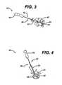
- FIGS. 1 to 8illustrate a distractor assembly system and method for inserting a spinal prosthesis.
- FIG. 1illustrates one embodiment of a distractor assembly 10 disclosed herein having a distractor or guide arm 12, a guide filler bar 26, and a modular handle 16. While the distractor 12 can have a variety of configurations that enable it to maintain the space between adjacent vertebrae following a discectomy, as shown in FIG. 2 , the distractor 12 has proximal and distal ends 12a, 12b with an elongate shaft 14 extending therebetween. Attached to the proximal end 12a of the distractor 12 is a handle 16 (or a portion thereof) for gripping by the surgeon.
- the handle 16can be either fixedly or removably attached, in an exemplary embodiment, the handle 16 is removably attached to the shaft 14 by any means known in the art, such as, for example, a screw or a spring plunger, so that the surgeon can remove it to achieve increased visibility to the surgical site.
- an elongate shaft 14Extending distally from the handle 16 is an elongate shaft 14. While the shaft 14 can have a variety of sizes, it should have a diameter that, upon insertion into the intervertebral space, allows sufficient space for the insertion of other surgical tools, such as a filler bar or an inserter for example, as well as an implant. Additionally, the shaft 14 can have a variety of shapes, such as circular, ovular, rectangular or square. As shown, the shaft 14 is rectangular and generally flat.
- the shaft 14can also have a variety of configurations that allow for mating with another surgical instrument, such as, for example, a filler bar, an inserter, a funnel, or any other instrument used in the implanting of a spinal prosthesis.
- the shaft 14can have a guide feature 18 such as a tooth or groove that can mate with a corresponding guide feature on another surgical instrument.
- the guide feature 18can be formed either throughout the entire length of the shaft 14 or on a partial length thereof.
- the guide feature 18can also have a variety of configurations depending upon the mating features of the corresponding surgical instrument.
- the guide feature 18can be protrude from the shaft 12, or, alternatively, the guide feature 18 can be recessed within the shaft 12.
- the guide feature 18can also have a variety of shapes, however in an exemplary embodiment, the guide feature 18 has a C-shape with two opposed sides that are either straight or curved.
- outer features, including the cross-sectional shape of the shaft itself,can form mating or guiding features.
- a distracting paddle 22Attached to the distal-most end of the shaft 14 is a distracting paddle 22 that, upon insertion into the cavity, can be rotated to distract adjacent vertebrae to maintain the integrity of the cavity between them.
- paddle 22has proximal and distal ends 22a, 22b connected by superior and inferior sides 22c, 22d and having a front or guiding face 22e and a back face 22f. While paddle 22 can have a variety of shapes, such as rectangular, circular or oblong, the illustrated paddle 22 is generally rectangular with rounded corners.
- the paddle 22can also have a variety of sizes to provide a desired level of distraction, so long as it has a width that is less than the diameter of any access portal into the intervertebral space. In an exemplary embodiment, the paddle 22 has a width that is less than about 19mm, and more preferably about 7mm.
- the paddlemay also be shaped so as to provide an angle between the inferior and superior sides to match a desired angle of distraction.
- the paddle 22can have a variety of additional features to assist the surgeon with distraction, which can be used alone or in combination with one another.
- the distal end 22b of the paddle 22can be arcuate to allow for easier insertion into the intervertebral space 42.
- the superior and/or inferior sides 22c, 22dcan have various geometries to enhance the distraction of the intervertebral space 42, such as laterally extending surfaces that provide a larger surface area to contact the vertebrae.
- the back side 22fcan also be dome-shaped to aid the surgeon in minimizing damage to the neural tissue surrounding the intervertebral space 42.
- One of superior and inferior sides 22c, 22dcan also be provided with a bone engaging element such as one or more teeth to prevent migration of the paddle during distraction.
- guide surface 22e of the paddle 22can include at least one guide feature such as guide feature 18 extending from the shaft 14 to engage a corresponding element in an implant or implant inserter.
- the implant or implant insertercan be guided by a flat guide surface 22e or by external features of the shaft 14.
- a filler bar 26can be removably mated to the distractor 12 to provide rigidity and torque strength to the distractor 12 during insertion into the cavity 42 and distraction of the adjacent vertebrae.
- the filler bar 26has proximal and distal ends 26a, 26b with a shaft 28 extending therebetween.
- the proximal end 26acan have a variety of configurations to assist the surgeon with placement and removal of the filler bar 26 from the distractor 12, however as shown the filler bar 26 has a T-shaped handle 30.
- the proximal end of the filler barcan include a portion of a handle that can mate with a corresponding handle portion on a distractor, such that when mated together, a complete handle is formed.
- the handle portionscan mate to one another in a variety of ways, in an exemplary embodiment, the handle portions are mated together by a spring lock mechanism.
- Extending distally from the T-shaped handle 30is an elongate shaft 28. While the shaft 28 can have a variety of sizes, as shown it has a diameter that is less than the diameter of the distractor. Additionally, the shaft 28 can have a guide feature 32 that corresponds to the guide feature 18 on the distractor 12. That is, the guide feature 32 can be either protruding or recessed, and have a variety of shapes, such as C-shaped with two opposed sides that can be either straight or curved. While the guide feature 32 can be formed throughout the entire length of the shaft 28 or on a partial length thereof, as shown, the groove 32 is formed throughout the entire length of the shaft 28.
- the plate 34can have any size so long as it is able to fit within the intervertebral space alongside the distractor 12, however in an exemplary embodiment the plate 34 is shaped such that it can nest within the distracting paddle 22, and in particular, within the laterally extending portions of superior and inferior surfaces 22c, 22d. Thus, in an exemplary embodiment, the plate 34 has width that is slightly smaller than the distracting paddle 22 and complementary in shape thereto.
- an implant insertercan be used with the distractor to form a distraction and insertion system.
- the insertercan be similar to inserters known in the art, as well as the inserter 46 shown in FIGS. 7 and 8 .
- the inserter 46has proximal and distal ends 46a, 46b with a shaft 52 extending therebetween. While the proximal end 46a can have a variety of configurations, in an exemplary embodiment it can have a handle (or a portion thereof) fixedly or removably attached thereto.
- the shaft 52can have a variety of configurations, the shaft 52 can also optionally include a guide feature 50 that corresponds to the guide feature 18 on the distractor 12, such that the inserter 46 can be mated to the distractor 12.
- the guide feature 50 on the inserter 46can be either protruding or recessed, and can be, for example, C-shaped with two opposed sides that are either straight or curved.
- the guide feature 50 on the inserter 46can be formed either throughout the entire length of the shaft 52 or on a partial length of the shaft 52.
- the insertermay simply be guided by a flat surface on the shaft 14 and/or paddle 22 on the distractor 12 or by an external feature of the shaft 14 such as, for example, its superior and/or inferior surfaces.
- an implant 48Removably mated to the distal most end of the shaft 52 is an implant 48, various embodiments of which will be discussed below.
- the distraction assembly 10is inserted into the intervertebral space 42 (that is, the space between superior and inferior vertebrae 41, 43) following the excision of disk material.
- the distraction assembly 10is then rotated approximately 90° such that the paddle 22 is substantially perpendicular to the superior and inferior vertebrae 41, 43, so as to enlarge and/or maintain a desired space within the cavity 42 by the force applied to the vertebrae by superior and inferior surfaces 22c, 22d during rotation.
- an access portsuch as cannula 51.
- the filler bar 26can be removed from the distractor 12 to decrease the amount of space that the assembly 10 requires in order to make room for further tools and/or implants as well as to improve the surgeon's ability to visualize the cavity.
- an inserter 46can then be slidably guided by the distractor 12. Specifically, the surgeon slidably mates the guide features 18, 32, if any, on the distractor 12 and the inserter 46 to one another, and the inserter 46 is slid distally along the distractor 12 into the intervertebral space 42. Once the inserter 46 is placed within the cavity 42, the implant 48 can then be maneuvered so as to achieve the desired orientation.
- the distractor assembly disclosed hereincan also optionally include a measurement system (not shown).
- the measurement systemcan be any indication that allows a surgeon to determine the depth of placement of the distractor, a trial implant or the implant. In an exemplary embodiment, however, the measurement system is formed along the entire length of the shafts of the distractor, filler bar, and/or inserter, or only on a portion thereof.
- the distractorcan included at least one colored band so as to color code for the height of the distraction paddle that the distractor can be matched to a similarly color coded trial implant and/or implant so that a surgeon can readily ensure that all are of the same height.
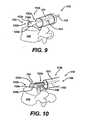
- FIGS. 9 to 43illustrate distractors having features that assist a surgeon in inserting an implant into an intervertebral space at a desired angle.
- the distractors described belowcan have features and methods of use similar to those of distractor 12 discussed above.
- FIGS. 9 to 11illustrate a distractor 112 that includes a paddle 122 having an angled distal end 122b, and thus providing an angled guide surface 122c.
- an implantis designed for placement at a certain angle of trajectory between the adjacent vertebrae and/or a surgeon chooses a particular angle of placement in order to achieve desired fusion characteristics.
- Minimally invasive approaches to the disk spaceprovide well documented advantages, however, establishing a minimally invasive access portal while sparing sensitive nerve tissues from contact and possible damage requires approach angles to the disk space that may not match the desired angle of placement of the implant. For example, a typical TLIF approach may take a 35° angle (plus or minus depending on the anatomy of a particular patient) while the desired angle for placement of the implant may be 45°.
- Providing an angled distal end 122b on the distractor paddle 122allows the surgeon to carefully guide the implant during insertion to the desired angle with a reduced chance of contacting sensitive nerve tissue. While the distal end 122b of the paddle 122 can have a variety of angles as desired by the surgeon, in the illustrated embodiment, the distal end 122b of the paddle 122 has an angle of about 20°.
- Paddle 122can further include opposed overhanging tabs 123a, 123b and a curved distal end 122b.
- the overhanging tabs 123a, 123bcan be any configuration that can serve as a guide for the implant 148, however, as shown, the overhanging tabs 123a, 123b are rectangular and extend horizontally from the guide surface 122c of the paddle 122.
- the overhanging tabs 123a, 123b of the paddle 122can slidingly engage the outer edge surfaces of the implant 148. Once engaged, the implant 148 is guided along the length of the paddle 122. As the implant 148 approaches the distal end 122b of the paddle 122, the angled distal end 122b urges the implant 148 into the desired orientation within the intervertebral space 142.
- FIGS. 12 to 13illustrate an angled distractor 212 that includes a shape memory metal shim 211. While the metal shim 211 can have any configuration to allow for the angled insertion of an implant 248, as shown the memory metal shim 211 is provided as a separate element from the distractor 212 that is placed along the side of the shaft 214 and paddle 222 of the distractor 212. Shim 211 can be held flat to the shaft 214 and/or paddle 222 of the distractor by one or more guide elements 213.
- extension of the shim 211 distally along the paddle 222causes the shim to return to a curved shape.
- the angle of curvature of the shape memory metal shim 211can be any angle that allows a surgeon to implant an spinal prosthesis into an intervertebral space 242, however in an exemplary embodiment, the curve of the shim 211 has an angle of about 20°.
- An implant 248is then inserted into the intervertebral space 142 and, upon contact with the shim 211, is directed towards the desired placement angle within the intervertebral space 242.
- the shim 211can also be retracted/straightened so that retraction of the distractor 212 does not displace the implant and so that retraction of the distractor does not disturb sensitive tissue.
- the shim 211can be made of any biocompatible material known to have shape memory or superelastic properties such as, for example, the NITINOL (an acronym for Nickel Titanium Naval Ordnance Laboratory) family of intermetallic materials, which contain a nearly equal mixture of nickel (55 wt. %) and titanium.
- NITINOLan acronym for Nickel Titanium Naval Ordnance Laboratory
- the shim 211conform to the shape of the distractor 212 during insertion and then retain its curved shape once it is placed within the intervertebral space 242 allows for a reduced profile for insertion and retraction through a minimally invasive surgical access point.
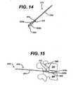
- FIGS. 14 to 17illustrate a distractor 312 that includes a paddle 322 having a shape memory metal shim 311 similar to metal shim 211 (described above), as well as extension shoulders 333a, 333b. While the extension shoulders 333a, 333b can have a variety of configurations, in an exemplary embodiment, they are slidably located on the paddle 322 and expendable from the superior and inferior sides thereof. However, in an alternate embodiment (not shown), a single extension shoulder can be formed on the paddle.
- extension shoulders 333a, 323bcan increase the height of the paddle 322 by any amount as desired by the surgeon to achieve and maintain a desired level of distraction of intervertebral space 342, in an exemplary embodiment, the paddle has a height of approximately 7mm and extension shoulders 333a, 333b increase the diameter of the paddle 322 by an amount up to approximately 4mm.
- the memory metal shim 311extends beyond the distal end 322b of the paddle 322, and retains its curved shape, such that the surgeon can place the implant 348 into the cavity 342 at a desired angle.
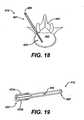
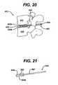
- FIGS. 18 to 20illustrate a distractor 412 having an internal shim 409, as well as extension shoulders 433a, 433b.
- the internal shim 409can be formed in a variety of ways, as shown the internal shim is 409 is formed within a sheath 407 surrounding the shaft 414 of the distractor 412.
- the internal shim 409can also include an expansion mechanism such that, in use, and similar to the memory metal shim 211 discussed above, the internal shim 409 drives the extension shoulders 433a, 433b upward and downward, respectively, as the surgeon desires.
- the expanding shoulders 533a, 533b of a distractor 512can be driven by an internal shim 509 having a linkage assembly 505.
- the linkage assembly 505can be formed in a variety of ways, as shown the linkage assembly 505 is also formed within a sheath 507 surrounding the shaft 514 of the distractor 512.
- the internal shim 509can drive the linkage assembly 505 to control the height of the extension shoulders 533a, 533b as desired.
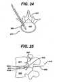
- FIGS. 24 to 26illustrate a distractor 612 having an inserter arm 660 for positioning the distractor.
- Distractor 612can include an internal shim 609 and extension shoulders 633a, 633b, similar to those as discussed above.
- the inserter arm 660can be removed after placement of the distractor 612, and a cable 662 is left behind extending distally from the distractor 612.
- the shim 609drives the extension shoulders 633a, 633b to set a height adjustment, similar to that as described above with respect to extension shoulders 333a, 333b.
- the inserter arm 660can be slidably removed from the cable 662, resulting in the cable 662 extending out of the intervertebral space 642.
- the cable 662can then either be removed or used as a guide for other surgical instruments.
- the shim 609can also optionally include a sliding support 613 that can be slid along the shaft 614 of the distractor 612 to lock the extension shoulders 633a, 633b in place, and help secure the distracted height of the cavity 642.
- the cable 662can be made from a variety of materials depending upon its desired use by the surgeon. For example, if the surgeon desires the cable to be used as a guide for future instruments or procedures, the cable can be made of any desirable surgical material of sufficient guide strength.
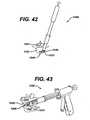
- FIGS. 27 to 36illustrate implant inserters having features that assist a surgeon in inserting an implant into an intervertebral space at a desired angle.
- the inserters of the embodiments described belowcan have features and can be used in a manner similar to that of inserter 46, discussed above.
- the shafts of the inserters in the embodiments described belowmay or may not include a guide feature for slidably engaging with another surgical instrument.
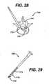
- FIGS. 27 to 29illustrate an inserter 746 that includes a hinge pivot joint 770 and a linkage mechanism 772. While the hinge pivot joint 770 and the linkage mechanism 772 can have a variety of configurations to drive the implant 748 to desired angulations, in one embodiment, the hinge pivot joint 770 and a linkage mechanism 772 are formed at the distal end 746b of the inserter 746, and located external to the shaft 752 thereof. Alternatively, the hinge pivot joint 770 and the linkage mechanism 772 can be formed within a pathway (not shown) contained within the shaft 752 of the inserter 746.
- the inserter 746can also include a variety of means by which the surgeon can control the hinge pivot joint 770 and the linkage assembly 772, such as, for example, a spring bias built into or placed on the pivot joint, and control the movement in response to the bias by proximal or distal movement of the linkage assembly.
- the surgeoncan maneuver the linkage mechanism such that the hinge pivot joint 770 and a linkage mechanism 772 cooperate to place the implant 748 at a desired angle.
- FIGS. 30 to 33show another inserter 846 that includes mating impaction arms 878a, 878b to rotate the implant 848 to the desired orientation. While the mating impaction arms 878a, 878b can rotate the implant 848 in a variety of ways, as shown, the mating impaction arms 878a, 878b include a mating face 879 that allows high impaction forces on the implant 848 by maintaining a high surface area of contact. Handle or knob 883 is rotated to drive the impaction arms relative to each other so as to rotate the implant, and the position of the knob can indicate the angle to which the implant is rotated as can be seen in the differential angulations illustrated by comparing FIGS. 30 and 31 .
- the mating face 879can have any configuration, but preferably allows for a high surface area contact with the implant 848, however in an exemplary embodiment the mating face 879 includes an adjustable driving mechanism having a movable protrusion 881 mated to the cavity of an implant 848.
- FIG. 32illustrates an up close view of the translating impaction arms described above for an inserter that allows for implant rotation during insertion.
- the implant 848includes an internal cavity 885 in which a inserter driver 881 mates while allowing the implant to rotate.
- the implant 848is loaded by inserting the driver 881 into the implant cavity 885 and rotating the driver 90 degrees as illustrated in FIG. 34 (loading position) and FIG. 33 (insertion position).
- the implant 848can be removed from the inserter by rotating the implant 90 degrees, in the reverse of the loading step for example.
- FIGS. 34 to 35illustrates another inserter 946 that allows cable rotation of implant 948 with respect to vertebra 941 by a cable 962 that is linked to the implant 948.
- Inserter shaft 952permits rotation of the implant in a hinge-like manner when the cable 962 is operated by the surgeon to drive the rotation.
- the cable 962must be disengaged from at least one of the implant 948 (in which case the cable 962 is removed with the shaft 952) or the shaft 952 (in which case the cable 962 is left behind with the implant 948). If the cable 962 is left behind, it can be formed, for example, from a bioabsorbable material.
- FIG. 36illustrates an exemplary implant driver 1346 that can be used with inserter 946 to permit rotation of the implant 1348.
- the implant 1348includes an external boss feature 1387 that is held between two inserter tabs 1388a, 1388b.
- the inserter tabs 1388a, 1388bcan have a variety of configurations, however in an exemplary embodiment, they include an inserter tab movement mechanism that allows a surgeon to adjust the angulation of the implant 1348, for example by using cable 962 from the embodiment of FIGS. 34 and 35 .
- external boss feature 1387 and tabs 1388a, 1388bare the inverse of cavity 885 and inserter driver 881 from the embodiment of FIGS. 32 and 33 . Both configurations can allow angulation of the implant, but by contact with external and internal surfaces of the implant respectively.
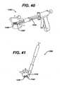
- the insertercan have a controlled insertion feature to allow incremental insertion and placement of an implant 1048, such as, for example a ratchet gun.
- an implant 1048such as, for example a ratchet gun.
- the ratchet gun inserter 1080can include a flexible sheath 1081 to protect the neural tissue from injury during insertion into the intervertebral space 1042 of implant 1048 through minimally invasive access port 1082.
- Ratchet gun inserter 1080can further include a flexible inserter connection 1085, such as metal laser cut tubing or helical springs, can be used to allow for implant rotation as described in other embodiments.
- FIGS. 38 and 39show a ratchet gun 1180 that includes distraction paddles 1184a, 1184b. While the distraction paddles 1184a, 1184b can have a variety of configurations known in the art, in an exemplary embodiment, they extend from the distal most end of the ratchet gun and are shaped and sized such that they fit against the inner surfaces of the superior and inferior vertebrae 1141, 1143. As this embodiment includes paddle distractors, inserter 1180 is not intended to be guided by a paddle distractor as with embodiments described above.
- the surgeoninserts the ratchet gun inserter 1180 into the intervertebral space 1142 and squeezes the handle of the gun (likely repeatedly) so that implant 1148 slides between distraction paddles 1184a, 1184b and extends the paddles away from each other to distract the intervertebral space 1142.
- a ratchet gun inserter 1280can include a rotating inserter 1247 that can have any configuration as described herein (above in FIGS. 27 to 36 ).
- the ratchet gun 1280can include a memory metal shim 1211, such as that described in FIGS. 12 and 13 above to allow insertion of an implant at a desired angulation.
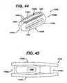
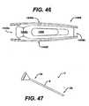
- a variety of implantscan be used with the instruments disclosed above, such as, for example, the implants disclosed in U.S. Patent No. 4,743,256 to Brantigan , U.S. Patent No. 4,834,757 to Brantigan , U.S. Patent No. 4,878,915 to Brantigan , U.S. Patent No. 5,192,327 to Brantigan , U.S. Patent No. 5,425,772 to Brantigan , U.S. Patent No. 5,716,415 to Steffee , U.S. Patent No. 5,984,922 to Mckay , U.S. Patent No. 6,245,108 to Biscup , as well as the implants disclosed in FIGS. 44 to 46 .
- the implant 1448has opposed front and back ends 1448 a, 1448b and parallel side surfaces 1448c, 1448d.
- Upper and lower surfaces 1448e, 1448f that engage the adjacent vertebraeextend between the side surfaces 1448c, 1448d, and such a cavity 1493 is formed within the center of the implant 1448.
- the back end 1448b of the implant 1448can have a profile and features to mate with an inserter instrument such as are known in the art or as described above. Additionally, at least one slot 1490 for vascularization can be formed in at least one of the parallel side surfaces 1448c, 1448d and/or the upper and lower surfaces 1448e, 1448f. While the slots 1490 can have a variety of shapes, e.g., circular, ovular, spherical, as shown the slot is ovular.
- At least one of the parallel side surfaces 1448c, 1448d and/or the upper and lower surfaces 1448e, 1448fhas a plurality of pyramid-shaped teeth 1492 formed thereon and extending outward to contact the superior and inferior vertebral surfaces 41, 43 and to resist retropulsion of the implant during or after insertion.
- the front end 1448a of the implant 1448can have a geometry that allows for entry into the disk past neural elements and for easier manipulation in the disk space. While this geometry can have a variety of forms, in an exemplary embodiment, it is a bullet-shaped profile, with a bulleted front profile in at least one, but preferably two planes. One skilled in the art will appreciate that the implant having a bullet formed in two planes is able to more effectively distract the vertebrae and neural tissue. ,
- the interior of the parallel side surfaces 1448c, 1448d and/or the upper and lower surfaces 1448e, 1448fcan include a plurality of ridges 1491 formed thereon for the maximum retention of the bone graft material within the cavity 1493.
- the ridges 1491can have a variety of shapes, in an exemplary embodiment the ridges 1491 can be slots that extend vertically along the interior surface of the parallel side surfaces 1448c, 1448d and/or the upper and lower surfaces 1448e, 1448f.
- the ridges 1491can be slots that horizontally extend along the inner surface of the parallel side surfaces 1448c, 1448d and/or the upper and lower surfaces 1448e, 1448f.
- the inner surfaces of the parallel side surfaces 1448c, 1448d and/or the upper and lower surfaces 1448e, 1448fcan include both vertically and horizontally extending ridges 1491.
- upper surface 1448e of the implant 1448can have a dome structure formed thereon. While the dome can have a variety of configurations, in an exemplary embodiment the dome is angled such that it corresponds to the shape of the superior and inferior vertebrae at a desired angle of rotation. One skilled in the art will appreciate that this implant allows for insertion at an angle that is approximately 35° off of the midline of the vertebrae.
- the materials used for forming the implants disclosed hereincan vary.
- One preferred material from which the implant can be madeis a carbon fiber reinforced polymer.
- Other materials from which the implants can be madeinclude metals, metal alloys, biologically compatible polymers, allograft bone, and combinations of these materials.
- suitable polymersinclude polyether sulfone, polycarbonate, and bioabsorbable polymers, and examples of suitable composites include carbon fiber reinforced polymers.
- suitable metalsinclude titanium, stainless steel, tantalum, cobalt chromium, aluminum, and combinations thereof.
- a graft material funnel 2can also be used with the distractor assembly disclosed herein.
- the graft material funnel 2has proximal and distal ends 2a, 2b connected by a shaft 6.
- the proximal end 2acan have a variety of features known in the art to contain bone graft material to be siphoned into the implant.
- the shaft 6can have a variety of configurations, such as elongate or curved, as shown it is curved.
- the curved shape of the shaftallows rotation to implant graft material to a desired location.
- the shaft 6can be made from a variety of materials, in an exemplary embodiment, the shaft 6 is made from a material that allows for the shaft diameter to have some flexibility, such that the graft material can be introduced into the funnel 2 without clogging.
- the instruments described hereincan be made from any suitable surgical grade material, including surgical grade stainless steel, titanium, aluminum, tantalum, cobalt chromium, plastics, and combinations and copolymers thereof.
Landscapes
- Health & Medical Sciences (AREA)
- Engineering & Computer Science (AREA)
- Biomedical Technology (AREA)
- Orthopedic Medicine & Surgery (AREA)
- Life Sciences & Earth Sciences (AREA)
- Transplantation (AREA)
- Animal Behavior & Ethology (AREA)
- Veterinary Medicine (AREA)
- Public Health (AREA)
- Heart & Thoracic Surgery (AREA)
- General Health & Medical Sciences (AREA)
- Cardiology (AREA)
- Vascular Medicine (AREA)
- Oral & Maxillofacial Surgery (AREA)
- Neurology (AREA)
- Surgery (AREA)
- Physical Education & Sports Medicine (AREA)
- Nuclear Medicine, Radiotherapy & Molecular Imaging (AREA)
- Medical Informatics (AREA)
- Molecular Biology (AREA)
- Prostheses (AREA)
- Electrotherapy Devices (AREA)
- Surgical Instruments (AREA)
Abstract
Description
- The present invention relates to surgical instruments, and in particular to methods and devices for implanting spinal prostheses.
- Spinal fusion surgeries, that is, the use of bone graft material to promote specific vertebrae to grow together into a solid and stable construct, are a common method of treating patients with severe back pain. For fusion to occur within the disc space, the surgeon must first remove the damaged disk material. Once the disk material is removed, the empty space left between the upper and lower vertebrae is distracted to relieve pressure from neural elements and to provide space for entry of surgical tools and/or implants. A bone graft, or interbody cage with bone, is then inserted into the empty disc space to promote bone growth from vertebral body to vertebral body. Recently, minimally invasive techniques have improved fusion procedures by causing less damage to tissue surrounding the damaged disk and allowing for faster recovery by the patient.
- One drawback associated with current instruments used to perform spinal fusion surgery, especially minimally invasive surgery, is that they typically provide inadequate protection for sensitive nerve tissue surrounding the surgical site. The smaller access portals used in minimally invasive surgery allow sensitive tissue to be located very close to the surgical site. Further, using current instruments within these tight confines often impedes the surgeon's visibility, making the ultimate placement of the implant difficult.
- The closest prior art is disclosed in the US publication no.
US 2003/0135275 . - Accordingly, there remains a need for improved surgical instruments, and in particular for surgical instruments used for implanting spinal prostheses.
- Disclosed herein are devices for implanting spinal prostheses. According to the invention, a surgical instrument system includes a distractor having a shaft, a paddle located at the distal end of the shaft, and a filler bar shaped to removably engage the shaft and paddle of the distractor. When the filler bar is engaged to the distractor, the filler bar provides rigidity and torque strength so that the distractor can be inserted between adjacent vertebrae in a first orientation and rotated to distract adjacent vertebrae.
- Preferred embodiments are defined in the dependent claims.
- The invention will be more fully understood from the following detailed description taken in conjunction with the accompanying drawings, in which:
FIG. 1 is a side perspective view of one embodiment of a distractor assembly;FIG. 2 is a side perspective view of one embodiment of the distractor of the distractor assembly ofFIG. 1 ;FIG. 3 is a side perspective view of the distractor assembly ofFIG. 1 upon insertion into an intervertebral space;FIG. 4 is a top perspective view of the distractor assembly ofFIG. 1 upon insertion into an intervertebral space;FIG. 5 is side perspective view of the distractor assembly ofFIG. 1 upon insertion into an intervertebral space;FIG. 6 is another side perspective view of the distractor assembly ofFIG. 1 upon insertion into an intervertebral space;FIG. 7 is a side perspective view of an implant being inserted into an intervertebral space using the distractor assembly ofFIG. 1 ;FIG. 8 is another side perspective view of an implant being inserted into an intervertebral space using the distractor assembly ofFIG. 1 ;FIG. 9 is a side perspective view of another distractor;FIG. 10 is a side perspective view of an implant being inserted into an intervertebral space using the distractor ofFIG. 9 ;FIG. 11 in another side perspective view of an implant being inserted into an intervertebral space using the distractor ofFIG. 9 ;FIG. 12 is a side perspective view of another distractor being inserted into an intervertebral space;FIG. 13 is a side perspective view of an implant being inserted into an intervertebral space using the distractor ofFIG. 12 ;FIG. 14 is a side perspective view of another distractor;FIG. 15 is a side perspective view of the distractor ofFIG. 14 upon insertion into an intervertebral space;FIG. 16 is another side perspective view of the distractor ofFIG. 14 upon insertion into an intervertebral space;FIG. 17 is a side perspective view of an implant being inserted into an intervertebral space using the distractor assembly ofFIG. 14 ;FIG. 18 is a side perspective view of another distractor upon insertion in an intervertebral space;FIG. 19 is a side perspective view of the distractor ofFIG. 18 ;FIG. 20 is another side perspective view of the distractor ofFIG. 18 upon insertion into an intervertebral space;FIG. 21 is a side perspective view of another distractor;FIG. 22 is a side perspective view of the distractor ofFIG. 21 upon insertion into an intervertebral space;FIG. 23 is another side perspective view of the distractor ofFIG. 21 ;FIG. 24 is a side perspective view of another distractor upon insertion into an intervertebral space;FIG. 25 is another side perspective view of the distractor ofFIG. 24 upon insertion into an intervertebral space;FIG. 26 is another side perspective view of the distractor ofFIG. 24 upon insertion into an intervertebral space;FIG. 27 is a side perspective view of an implant being inserted into an intervertebral space using an inserter;FIG. 28 is another side perspective view of an implant being inserted into an intervertebral space using the inserter ofFIG. 27 ;FIG. 29 is a side perspective view of the inserter ofFIG. 27 ;FIG. 30 is a side perspective view of another inserter;FIG. 31 is another side perspective view of the inserter ofFIG. 30 ;FIG. 32 is a magnified view of the distal end of the inserter ofFIG. 30 ;FIG. 33 is another magnified view of the distal end of the inserter ofFIG. 30 ;FIG. 34 is a side perspective view of an implant being inserted into an intervertebral space using another inserter;FIG. 35 is another side perspective view of an implant being inserted into an intervertebral space using the inserter ofFIG. 34 ;FIG. 36 is a side perspective view of another inserter;FIG. 37 is a side perspective view of an implant being inserted into an intervertebral space using another inserter;FIG. 38 is a side perspective view of another distractor assembly;FIG. 39 is a side perspective view of the distractor assembly ofFIG. 38 upon insertion into an intervertebral space;FIG. 40 is a side perspective view of another distractor assembly upon insertion into an intervertebral space;FIG. 41 is another side perspective view of an implant being inserted into an intervertebral space using the distractor assembly ofFIG. 40 ;FIG. 42 is a side perspective view of an implant being inserted into an intervertebral space using another distractor assembly;FIG. 43 is another side perspective view of the distractor assembly ofFIG. 42 upon insertion into an intervertebral space;FIG. 44 is a side perspective view of an implant;FIG. 45 is a side perspective view of the implant ofFIG. 44 ;FIG. 46 is another side perspective view of the implant ofFIG. 44 ; andFIG. 47 is a side perspective view of a funnel.- Disclosed herein are methods and devices for distracting adjacent vertebrae and/or inserting spinal implants during surgical procedures for repairing a patient's spine. In an exemplary embodiment, a distractor is disclosed that maintains the empty space between adjacent vertebrae following a discectomy, and that can removably mate with other surgical instruments, such as, for example, a filler bar, an implanting tool, or a funnel. Furthermore a distractor is disclosed having various features to assist in implanting a spinal prosthesis, such as, for example, an angled distal end and/or an expandable paddle. Also, an articulating inserter is disclosed. Moreover, various implants and funnels are also disclosed herein. A person skilled in the art will appreciate that, while the methods and devices are described in connection with certain spinal procedures, the methods and devices disclosed herein can be used for a variety of surgical procedures.
- Certain features and aspects of the present invention will now be described by reference to the distractor assembly and associated elements illustrated in
FIGS. 1 to 8 , which illustrate a distractor assembly system and method for inserting a spinal prosthesis. FIG. 1 illustrates one embodiment of adistractor assembly 10 disclosed herein having a distractor or guidearm 12, aguide filler bar 26, and amodular handle 16. While thedistractor 12 can have a variety of configurations that enable it to maintain the space between adjacent vertebrae following a discectomy, as shown inFIG. 2 , thedistractor 12 has proximal anddistal ends elongate shaft 14 extending therebetween. Attached to theproximal end 12a of thedistractor 12 is a handle 16 (or a portion thereof) for gripping by the surgeon. While thehandle 16 can be either fixedly or removably attached, in an exemplary embodiment, thehandle 16 is removably attached to theshaft 14 by any means known in the art, such as, for example, a screw or a spring plunger, so that the surgeon can remove it to achieve increased visibility to the surgical site.- Extending distally from the
handle 16 is anelongate shaft 14. While theshaft 14 can have a variety of sizes, it should have a diameter that, upon insertion into the intervertebral space, allows sufficient space for the insertion of other surgical tools, such as a filler bar or an inserter for example, as well as an implant. Additionally, theshaft 14 can have a variety of shapes, such as circular, ovular, rectangular or square. As shown, theshaft 14 is rectangular and generally flat. - The
shaft 14 can also have a variety of configurations that allow for mating with another surgical instrument, such as, for example, a filler bar, an inserter, a funnel, or any other instrument used in the implanting of a spinal prosthesis. In an exemplary embodiment, theshaft 14 can have aguide feature 18 such as a tooth or groove that can mate with a corresponding guide feature on another surgical instrument. Theguide feature 18 can be formed either throughout the entire length of theshaft 14 or on a partial length thereof. Theguide feature 18 can also have a variety of configurations depending upon the mating features of the corresponding surgical instrument. For example, in one embodiment, theguide feature 18 can be protrude from theshaft 12, or, alternatively, theguide feature 18 can be recessed within theshaft 12. Theguide feature 18 can also have a variety of shapes, however in an exemplary embodiment, theguide feature 18 has a C-shape with two opposed sides that are either straight or curved. In addition, outer features, including the cross-sectional shape of the shaft itself, can form mating or guiding features. - Attached to the distal-most end of the
shaft 14 is adistracting paddle 22 that, upon insertion into the cavity, can be rotated to distract adjacent vertebrae to maintain the integrity of the cavity between them. As shown, paddle 22 has proximal anddistal ends inferior sides face 22e and aback face 22f. Whilepaddle 22 can have a variety of shapes, such as rectangular, circular or oblong, the illustratedpaddle 22 is generally rectangular with rounded corners. Thepaddle 22 can also have a variety of sizes to provide a desired level of distraction, so long as it has a width that is less than the diameter of any access portal into the intervertebral space. In an exemplary embodiment, thepaddle 22 has a width that is less than about 19mm, and more preferably about 7mm. The paddle may also be shaped so as to provide an angle between the inferior and superior sides to match a desired angle of distraction. - The
paddle 22 can have a variety of additional features to assist the surgeon with distraction, which can be used alone or in combination with one another. In addition to those features discussed in more detail below, in one embodiment, thedistal end 22b of thepaddle 22 can be arcuate to allow for easier insertion into theintervertebral space 42. In addition, the superior and/orinferior sides intervertebral space 42, such as laterally extending surfaces that provide a larger surface area to contact the vertebrae. Theback side 22f can also be dome-shaped to aid the surgeon in minimizing damage to the neural tissue surrounding theintervertebral space 42. One of superior andinferior sides - Additionally the
paddle 22 can have a variety of features to assist the surgeon with positioning of theimplant 48 within theintervertebral space 42. In addition to those features discussed in more detail below, guidesurface 22e of thepaddle 22 can include at least one guide feature such as guide feature 18 extending from theshaft 14 to engage a corresponding element in an implant or implant inserter. Alternatively, the implant or implant inserter can be guided by aflat guide surface 22e or by external features of theshaft 14. - As noted above and referring back to
FIG. 1 , afiller bar 26 can be removably mated to thedistractor 12 to provide rigidity and torque strength to thedistractor 12 during insertion into thecavity 42 and distraction of the adjacent vertebrae. As shown inFIG. 1 , thefiller bar 26 has proximal anddistal ends shaft 28 extending therebetween. Theproximal end 26a can have a variety of configurations to assist the surgeon with placement and removal of thefiller bar 26 from thedistractor 12, however as shown thefiller bar 26 has a T-shaped handle 30. Alternatively, the proximal end of the filler bar can include a portion of a handle that can mate with a corresponding handle portion on a distractor, such that when mated together, a complete handle is formed. While the handle portions can mate to one another in a variety of ways, in an exemplary embodiment, the handle portions are mated together by a spring lock mechanism. - Extending distally from the T-shaped handle 30 is an
elongate shaft 28. While theshaft 28 can have a variety of sizes, as shown it has a diameter that is less than the diameter of the distractor. Additionally, theshaft 28 can have a guide feature 32 that corresponds to theguide feature 18 on thedistractor 12. That is, the guide feature 32 can be either protruding or recessed, and have a variety of shapes, such as C-shaped with two opposed sides that can be either straight or curved. While the guide feature 32 can be formed throughout the entire length of theshaft 28 or on a partial length thereof, as shown, the groove 32 is formed throughout the entire length of theshaft 28. - Fixedly attached to the distal most end of the
shaft 28 is a stabilizingplate 34. Theplate 34 can have any size so long as it is able to fit within the intervertebral space alongside thedistractor 12, however in an exemplary embodiment theplate 34 is shaped such that it can nest within thedistracting paddle 22, and in particular, within the laterally extending portions of superior andinferior surfaces plate 34 has width that is slightly smaller than thedistracting paddle 22 and complementary in shape thereto. - In a further embodiment, an implant inserter can be used with the distractor to form a distraction and insertion system. Generally, the inserter can be similar to inserters known in the art, as well as the
inserter 46 shown inFIGS. 7 and 8 . As shown inFIGS. 7 and 8 , theinserter 46 has proximal and distal ends 46a, 46b with ashaft 52 extending therebetween. While the proximal end 46a can have a variety of configurations, in an exemplary embodiment it can have a handle (or a portion thereof) fixedly or removably attached thereto. - Extending distally from the handle of the
inserter 46 is an elongate shaft. While theshaft 52 can have a variety of configurations, theshaft 52 can also optionally include a guide feature 50 that corresponds to theguide feature 18 on thedistractor 12, such that theinserter 46 can be mated to thedistractor 12. Thus, depending upon the configuration of theguide feature 18 on thedistractor 12, the guide feature 50 on theinserter 46 can be either protruding or recessed, and can be, for example, C-shaped with two opposed sides that are either straight or curved. Moreover, the guide feature 50 on theinserter 46 can be formed either throughout the entire length of theshaft 52 or on a partial length of theshaft 52. Alternatively, the inserter may simply be guided by a flat surface on theshaft 14 and/or paddle 22 on thedistractor 12 or by an external feature of theshaft 14 such as, for example, its superior and/or inferior surfaces. Removably mated to the distal most end of theshaft 52 is animplant 48, various embodiments of which will be discussed below. - In use, as shown in
FIGS. 3 to 8 , thedistraction assembly 10 is inserted into the intervertebral space 42 (that is, the space between superior andinferior vertebrae 41, 43) following the excision of disk material. Thedistraction assembly 10 is then rotated approximately 90° such that thepaddle 22 is substantially perpendicular to the superior andinferior vertebrae cavity 42 by the force applied to the vertebrae by superior andinferior surfaces FIGS. 5 to 8 , access to the surgical site can be gained using an access port such ascannula 51. - Following distraction of the
cavity 42, thefiller bar 26 can be removed from thedistractor 12 to decrease the amount of space that theassembly 10 requires in order to make room for further tools and/or implants as well as to improve the surgeon's ability to visualize the cavity. As shown inFIGS. 7 to 8 , aninserter 46 can then be slidably guided by thedistractor 12. Specifically, the surgeon slidably mates the guide features 18, 32, if any, on thedistractor 12 and theinserter 46 to one another, and theinserter 46 is slid distally along thedistractor 12 into theintervertebral space 42. Once theinserter 46 is placed within thecavity 42, theimplant 48 can then be maneuvered so as to achieve the desired orientation. - The distractor assembly disclosed herein can also optionally include a measurement system (not shown). The measurement system can be any indication that allows a surgeon to determine the depth of placement of the distractor, a trial implant or the implant. In an exemplary embodiment, however, the measurement system is formed along the entire length of the shafts of the distractor, filler bar, and/or inserter, or only on a portion thereof. In addition, the distractor can included at least one colored band so as to color code for the height of the distraction paddle that the distractor can be matched to a similarly color coded trial implant and/or implant so that a surgeon can readily ensure that all are of the same height.
- As noted above, the distractor assemblies disclosed herein can have a variety of features to assist in implanting the spinal prosthesis, such as those features shown in
FIGS. 9 to 43 . Specifically,FIGS. 9 to 26 illustrate distractors having features that assist a surgeon in inserting an implant into an intervertebral space at a desired angle. At the outset it should be noted that the distractors described below can have features and methods of use similar to those ofdistractor 12 discussed above. FIGS. 9 to 11 illustrate adistractor 112 that includes apaddle 122 having an angleddistal end 122b, and thus providing anangled guide surface 122c. Many times, an implant is designed for placement at a certain angle of trajectory between the adjacent vertebrae and/or a surgeon chooses a particular angle of placement in order to achieve desired fusion characteristics. Minimally invasive approaches to the disk space provide well documented advantages, however, establishing a minimally invasive access portal while sparing sensitive nerve tissues from contact and possible damage requires approach angles to the disk space that may not match the desired angle of placement of the implant. For example, a typical TLIF approach may take a 35° angle (plus or minus depending on the anatomy of a particular patient) while the desired angle for placement of the implant may be 45°. Providing an angleddistal end 122b on thedistractor paddle 122 allows the surgeon to carefully guide the implant during insertion to the desired angle with a reduced chance of contacting sensitive nerve tissue. While thedistal end 122b of thepaddle 122 can have a variety of angles as desired by the surgeon, in the illustrated embodiment, thedistal end 122b of thepaddle 122 has an angle of about 20°.- Paddle 122 can further include opposed overhanging
tabs distal end 122b. The overhangingtabs implant 148, however, as shown, the overhangingtabs guide surface 122c of thepaddle 122. - In use, as an inserter (such as inserter 146) is slid distally along the
shaft 114 of thedistractor 112, the overhangingtabs paddle 122 can slidingly engage the outer edge surfaces of theimplant 148. Once engaged, theimplant 148 is guided along the length of thepaddle 122. As theimplant 148 approaches thedistal end 122b of thepaddle 122, the angleddistal end 122b urges theimplant 148 into the desired orientation within the intervertebral space 142. FIGS. 12 to 13 illustrate anangled distractor 212 that includes a shapememory metal shim 211. While themetal shim 211 can have any configuration to allow for the angled insertion of animplant 248, as shown thememory metal shim 211 is provided as a separate element from thedistractor 212 that is placed along the side of theshaft 214 and paddle 222 of thedistractor 212.Shim 211 can be held flat to theshaft 214 and/or paddle 222 of the distractor by one ormore guide elements 213.- In use, extension of the
shim 211 distally along the paddle 222 (generally by pushing on a proximal end or feature of the shim) beyond theguide elements 213 causes the shim to return to a curved shape. The angle of curvature of the shapememory metal shim 211 can be any angle that allows a surgeon to implant an spinal prosthesis into anintervertebral space 242, however in an exemplary embodiment, the curve of theshim 211 has an angle of about 20°. Animplant 248 is then inserted into the intervertebral space 142 and, upon contact with theshim 211, is directed towards the desired placement angle within theintervertebral space 242. Theshim 211 can also be retracted/straightened so that retraction of thedistractor 212 does not displace the implant and so that retraction of the distractor does not disturb sensitive tissue. - The
shim 211 can be made of any biocompatible material known to have shape memory or superelastic properties such as, for example, the NITINOL (an acronym for Nickel Titanium Naval Ordnance Laboratory) family of intermetallic materials, which contain a nearly equal mixture of nickel (55 wt. %) and titanium. One skilled in the art will appreciate that the ability of theshim 211 conform to the shape of thedistractor 212 during insertion and then retain its curved shape once it is placed within theintervertebral space 242 allows for a reduced profile for insertion and retraction through a minimally invasive surgical access point. FIGS. 14 to 17 illustrate adistractor 312 that includes apaddle 322 having a shapememory metal shim 311 similar to metal shim 211 (described above), as well asextension shoulders paddle 322 and expendable from the superior and inferior sides thereof. However, in an alternate embodiment (not shown), a single extension shoulder can be formed on the paddle.- In use, following insertion into an
intervertebral space 342 and rotation of thepaddle 322 to a distracting position, the distal movement of theshim 311, and in particular, contact between drivingshoulders 313 on theshim 311 and the extension shoulders 333a, 333b, drives the extension shoulders 333a, 333b upward and downward, respectively, to further distract theintervertebral space 342. While extension shoulders 333a, 323b can increase the height of thepaddle 322 by any amount as desired by the surgeon to achieve and maintain a desired level of distraction ofintervertebral space 342, in an exemplary embodiment, the paddle has a height of approximately 7mm andextension shoulders paddle 322 by an amount up to approximately 4mm. By providing at least some of the distraction height by extension rather than rotation, a more sure placement of the distractor can be achieved with less movement within the cavity during distraction. Moreover, following extension of the extension shoulders 333a, 333b, thememory metal shim 311 extends beyond thedistal end 322b of thepaddle 322, and retains its curved shape, such that the surgeon can place theimplant 348 into thecavity 342 at a desired angle. FIGS. 18 to 20 illustrate adistractor 412 having aninternal shim 409, as well asextension shoulders internal shim 409 can be formed in a variety of ways, as shown the internal shim is 409 is formed within asheath 407 surrounding the shaft 414 of thedistractor 412. Theinternal shim 409 can also include an expansion mechanism such that, in use, and similar to thememory metal shim 211 discussed above, theinternal shim 409 drives the extension shoulders 433a, 433b upward and downward, respectively, as the surgeon desires.- Alternatively, as shown in
FIGS. 21 to 23 , the expandingshoulders distractor 512 can be driven by aninternal shim 509 having a linkage assembly 505. While the linkage assembly 505 can be formed in a variety of ways, as shown the linkage assembly 505 is also formed within asheath 507 surrounding the shaft 514 of thedistractor 512. In use, similar to the embodiment above, theinternal shim 509 can drive the linkage assembly 505 to control the height of the extension shoulders 533a, 533b as desired. FIGS. 24 to 26 illustrate adistractor 612 having an inserter arm 660 for positioning the distractor.Distractor 612 can include aninternal shim 609 andextension shoulders distractor 612, and acable 662 is left behind extending distally from thedistractor 612.- In use, the
shim 609 drives the extension shoulders 633a, 633b to set a height adjustment, similar to that as described above with respect toextension shoulders cavity 642 is distracted to the desired height, the inserter arm 660 can be slidably removed from thecable 662, resulting in thecable 662 extending out of theintervertebral space 642. Thecable 662 can then either be removed or used as a guide for other surgical instruments. One skilled in the art will further appreciate that theshim 609 can also optionally include a slidingsupport 613 that can be slid along the shaft 614 of thedistractor 612 to lock the extension shoulders 633a, 633b in place, and help secure the distracted height of thecavity 642. - The
cable 662 can be made from a variety of materials depending upon its desired use by the surgeon. For example, if the surgeon desires the cable to be used as a guide for future instruments or procedures, the cable can be made of any desirable surgical material of sufficient guide strength. FIGS. 27 to 36 illustrate implant inserters having features that assist a surgeon in inserting an implant into an intervertebral space at a desired angle. At the outset it should be noted that the inserters of the embodiments described below can have features and can be used in a manner similar to that ofinserter 46, discussed above. Moreover, depending upon the particular surgical assembly, the shafts of the inserters in the embodiments described below may or may not include a guide feature for slidably engaging with another surgical instrument.FIGS. 27 to 29 illustrate aninserter 746 that includes a hinge pivot joint 770 and alinkage mechanism 772. While the hinge pivot joint 770 and thelinkage mechanism 772 can have a variety of configurations to drive theimplant 748 to desired angulations, in one embodiment, the hinge pivot joint 770 and alinkage mechanism 772 are formed at the distal end 746b of theinserter 746, and located external to the shaft 752 thereof. Alternatively, the hinge pivot joint 770 and thelinkage mechanism 772 can be formed within a pathway (not shown) contained within the shaft 752 of theinserter 746. Theinserter 746 can also include a variety of means by which the surgeon can control the hinge pivot joint 770 and thelinkage assembly 772, such as, for example, a spring bias built into or placed on the pivot joint, and control the movement in response to the bias by proximal or distal movement of the linkage assembly. Thus, in use, the surgeon can maneuver the linkage mechanism such that the hinge pivot joint 770 and alinkage mechanism 772 cooperate to place theimplant 748 at a desired angle.FIGS. 30 to 33 show anotherinserter 846 that includesmating impaction arms implant 848 to the desired orientation. While themating impaction arms implant 848 in a variety of ways, as shown, themating impaction arms mating face 879 that allows high impaction forces on theimplant 848 by maintaining a high surface area of contact. Handle orknob 883 is rotated to drive the impaction arms relative to each other so as to rotate the implant, and the position of the knob can indicate the angle to which the implant is rotated as can be seen in the differential angulations illustrated by comparingFIGS. 30 and 31 .- The
mating face 879 can have any configuration, but preferably allows for a high surface area contact with theimplant 848, however in an exemplary embodiment themating face 879 includes an adjustable driving mechanism having amovable protrusion 881 mated to the cavity of animplant 848.FIG. 32 illustrates an up close view of the translating impaction arms described above for an inserter that allows for implant rotation during insertion. Theimplant 848 includes aninternal cavity 885 in which ainserter driver 881 mates while allowing the implant to rotate. Theimplant 848 is loaded by inserting thedriver 881 into theimplant cavity 885 and rotating the driver 90 degrees as illustrated inFIG. 34 (loading position) andFIG. 33 (insertion position). Theimplant 848 can be removed from the inserter by rotating the implant 90 degrees, in the reverse of the loading step for example. FIGS. 34 to 35 illustrates anotherinserter 946 that allows cable rotation ofimplant 948 with respect tovertebra 941 by acable 962 that is linked to theimplant 948.Inserter shaft 952 permits rotation of the implant in a hinge-like manner when thecable 962 is operated by the surgeon to drive the rotation. When theinserter shaft 952 is removed, thecable 962 must be disengaged from at least one of the implant 948 (in which case thecable 962 is removed with the shaft 952) or the shaft 952 (in which case thecable 962 is left behind with the implant 948). If thecable 962 is left behind, it can be formed, for example, from a bioabsorbable material.FIG. 36 illustrates anexemplary implant driver 1346 that can be used withinserter 946 to permit rotation of theimplant 1348. Theimplant 1348 includes anexternal boss feature 1387 that is held between twoinserter tabs inserter tabs implant 1348, for example by usingcable 962 from the embodiment ofFIGS. 34 and 35 . In one sense,external boss feature 1387 andtabs cavity 885 andinserter driver 881 from the embodiment ofFIGS. 32 and 33 . Both configurations can allow angulation of the implant, but by contact with external and internal surfaces of the implant respectively.- In other embodiments of the present invention, such as those shown in
FIGS. 37-43 , the inserter can have a controlled insertion feature to allow incremental insertion and placement of animplant 1048, such as, for example a ratchet gun. Such a gun may have a variety of configurations known in the art, as shown inFIG. 37 , theratchet gun inserter 1080 can include aflexible sheath 1081 to protect the neural tissue from injury during insertion into theintervertebral space 1042 ofimplant 1048 through minimallyinvasive access port 1082.Ratchet gun inserter 1080 can further include aflexible inserter connection 1085, such as metal laser cut tubing or helical springs, can be used to allow for implant rotation as described in other embodiments. FIGS. 38 and 39 show aratchet gun 1180 that includesdistraction paddles inserter 1180 is not intended to be guided by a paddle distractor as with embodiments described above.- In use, the surgeon inserts the
ratchet gun inserter 1180 into theintervertebral space 1142 and squeezes the handle of the gun (likely repeatedly) so thatimplant 1148 slides betweendistraction paddles intervertebral space 1142. - As further shown in
FIGS. 40 and 41 , aratchet gun inserter 1280, similar to ratchetgun inserter 1180, can include arotating inserter 1247 that can have any configuration as described herein (above inFIGS. 27 to 36 ). Alternatively, as shown inFIGS. 42 and 43 , theratchet gun 1280 can include a memory metal shim 1211, such as that described inFIGS. 12 and 13 above to allow insertion of an implant at a desired angulation. - A variety of implants can be used with the instruments disclosed above, such as, for example, the implants disclosed in
U.S. Patent No. 4,743,256 to Brantigan ,U.S. Patent No. 4,834,757 to Brantigan ,U.S. Patent No. 4,878,915 to Brantigan ,U.S. Patent No. 5,192,327 to Brantigan ,U.S. Patent No. 5,425,772 to Brantigan ,U.S. Patent No. 5,716,415 to Steffee ,U.S. Patent No. 5,984,922 to Mckay ,U.S. Patent No. 6,245,108 to Biscup , as well as the implants disclosed inFIGS. 44 to 46 . While the implants can have a variety of configurations, in an exemplary embodiment, as shown inFIG. 44 , theimplant 1448 has opposed front andback ends parallel side surfaces lower surfaces side surfaces cavity 1493 is formed within the center of theimplant 1448. - The
back end 1448b of theimplant 1448 can have a profile and features to mate with an inserter instrument such as are known in the art or as described above. Additionally, at least oneslot 1490 for vascularization can be formed in at least one of theparallel side surfaces lower surfaces slots 1490 can have a variety of shapes, e.g., circular, ovular, spherical, as shown the slot is ovular. Additionally, at least one of theparallel side surfaces lower surfaces teeth 1492 formed thereon and extending outward to contact the superior and inferior vertebral surfaces 41, 43 and to resist retropulsion of the implant during or after insertion. - Further, as shown in
FIG. 44 , thefront end 1448a of theimplant 1448 can have a geometry that allows for entry into the disk past neural elements and for easier manipulation in the disk space. While this geometry can have a variety of forms, in an exemplary embodiment, it is a bullet-shaped profile, with a bulleted front profile in at least one, but preferably two planes. One skilled in the art will appreciate that the implant having a bullet formed in two planes is able to more effectively distract the vertebrae and neural tissue. , - Further, the interior of the
parallel side surfaces lower surfaces ridges 1491 formed thereon for the maximum retention of the bone graft material within thecavity 1493. While theridges 1491 can have a variety of shapes, in an exemplary embodiment theridges 1491 can be slots that extend vertically along the interior surface of theparallel side surfaces lower surfaces ridges 1491 can be slots that horizontally extend along the inner surface of theparallel side surfaces lower surfaces parallel side surfaces lower surfaces ridges 1491. - In addition, as shown in
FIGS. 45 to 46 ,upper surface 1448e of theimplant 1448 can have a dome structure formed thereon. While the dome can have a variety of configurations, in an exemplary embodiment the dome is angled such that it corresponds to the shape of the superior and inferior vertebrae at a desired angle of rotation. One skilled in the art will appreciate that this implant allows for insertion at an angle that is approximately 35° off of the midline of the vertebrae. - The materials used for forming the implants disclosed herein can vary. One preferred material from which the implant can be made is a carbon fiber reinforced polymer. Other materials from which the implants can be made include metals, metal alloys, biologically compatible polymers, allograft bone, and combinations of these materials. Examples of suitable polymers include polyether sulfone, polycarbonate, and bioabsorbable polymers, and examples of suitable composites include carbon fiber reinforced polymers. Examples of suitable metals include titanium, stainless steel, tantalum, cobalt chromium, aluminum, and combinations thereof.
- As noted above a
graft material funnel 2 can also be used with the distractor assembly disclosed herein. As shown inFIG. 47 , thegraft material funnel 2 has proximal anddistal ends shaft 6. Theproximal end 2a can have a variety of features known in the art to contain bone graft material to be siphoned into the implant. While theshaft 6 can have a variety of configurations, such as elongate or curved, as shown it is curved. One skilled in the art will appreciate that the curved shape of the shaft allows rotation to implant graft material to a desired location. Additionally, while theshaft 6 can be made from a variety of materials, in an exemplary embodiment, theshaft 6 is made from a material that allows for the shaft diameter to have some flexibility, such that the graft material can be introduced into thefunnel 2 without clogging. - The instruments described herein can be made from any suitable surgical grade material, including surgical grade stainless steel, titanium, aluminum, tantalum, cobalt chromium, plastics, and combinations and copolymers thereof.
- One skilled in the art will appreciate further features and advantages of the invention based on the above-described embodiments. Accordingly, the invention is not to be limited by what has been particularly shown and described, except as indicated by the appended claims.
Claims (19)
- A surgical instrument system, comprising:a distractor including a shaft (14) and a paddle (22), the paddle being located on a distal end of the shaft;characterised in thata filler bar (26) is shaped to removably engage the shaft and paddle of the distractor;wherein when the filler bar is engaged to the distractor, the filler bar provides rigidity and torque strength so that the distractor can be inserted between adjacent vertebrae in a first orientation and rotated to distract the adjacent vertebrae.
- The system of claim 1, wherein the distractor paddle includes a first height dimension when presented in an insertion orientation and a second height dimension when rotated approximately 90 degrees to a distraction orientation, the second height dimension being greater than the first height dimension, the paddle having inferior and superior surfaces (22c,d) for contacting adjacent vertebrae in the distraction orientation.
- The system of claim 2, wherein the filler bar extends substantially along at least one side of the shaft and paddle.
- The system of claim 3, wherein the filler bar is dimensioned so as not to extend beyond the superior and inferior surfaces of the paddle.
- The system of claim 3, wherein the filler bar is slidably engageable to and removable from the distractor along a longitudinal axis of the distractor.
- The system of claim 2, wherein at least one of the inferior and superior surfaces of the paddle include a means for preventing migration of the distractor during distraction.
- The system of claim 6, wherein the means for preventing migration includes a bone engaging element.
- The system of claim 7, wherein the bone engaging element includes at least one tooth.
- The system of claim 6, wherein the means for preventing migration includes at least one expansion shoulder operable to extend beyond at least one of the inferior or superior surfaces so as to increase the second height dimension.
- The system of claim 2, wherein the distractor paddle and shaft present a guide surface for guiding the placement of an implant when the distractor is in the distraction orientation, and the distractor paddle further comprises an angled guide feature that is configured to guide an implant through a partial rotation to a desired angle.
- The system of claim 10, wherein the angled guide feature includes an angled surface integral with a distal portion of the paddle.
- The system of claim 10, wherein the angled guide feature is provided on a movable shim operable to extend from the guide surface to guide an implant through a partial rotation.
- The system of claim 12, wherein the movable shim is retractable.
- The system of claim 10, wherein the angled guide feature is formed from a shape memory material.
- The system of claim 10, further comprising an implant inserter having an angled distal end, the angle corresponding approximately to the angle provided on the angled guide feature.
- The system of claim 10, further comprising an implant inserter having an articulating implant holder operable to rotate an implant to a desired angle.
- The system of claim 2, further comprising a minimally invasive access port through which the distractor is dimensioned to be placed.
- The system of claim 2, further comprising a guide feature extending along the shaft and paddle, the guide feature configured for mating with at least one of an implant and an implant insterter to guide an insertion of an implant along the distractor.
- The system of claim 2, further comprising at least one overhanging tab provided on at least one of the inferior and superior surfaces.
Applications Claiming Priority (2)
| Application Number | Priority Date | Filing Date | Title |
|---|---|---|---|
| US54303004P | 2004-02-09 | 2004-02-09 | |
| PCT/US2005/004136WO2005077288A1 (en) | 2004-02-09 | 2005-02-09 | Systems and methods for spinal surgery |
Publications (3)
| Publication Number | Publication Date |
|---|---|
| EP1713408A1 EP1713408A1 (en) | 2006-10-25 |
| EP1713408A4 EP1713408A4 (en) | 2009-02-18 |
| EP1713408B1true EP1713408B1 (en) | 2010-09-15 |
Family
ID=34860360
Family Applications (1)
| Application Number | Title | Priority Date | Filing Date |
|---|---|---|---|
| EP05713229AExpired - LifetimeEP1713408B1 (en) | 2004-02-09 | 2005-02-09 | Systems for spinal surgery |
Country Status (9)
| Country | Link |
|---|---|
| US (3) | US8016829B2 (en) |
| EP (1) | EP1713408B1 (en) |
| JP (1) | JP2007521886A (en) |
| AT (1) | ATE481035T1 (en) |
| AU (2) | AU2005212352B2 (en) |
| CA (2) | CA2793237C (en) |
| DE (1) | DE602005023583D1 (en) |
| ES (1) | ES2350584T3 (en) |
| WO (1) | WO2005077288A1 (en) |
Cited By (1)
| Publication number | Priority date | Publication date | Assignee | Title |
|---|---|---|---|---|
| US11931053B2 (en) | 2022-08-04 | 2024-03-19 | PTL Opco, LLC | Single-use joint decorticator apparatus |
Families Citing this family (93)
| Publication number | Priority date | Publication date | Assignee | Title |
|---|---|---|---|---|
| EP1713408B1 (en) | 2004-02-09 | 2010-09-15 | DePuy Spine, Inc. | Systems for spinal surgery |
| US7641690B2 (en) | 2004-08-23 | 2010-01-05 | Abdou M Samy | Bone fixation and fusion device |
| WO2006041963A2 (en) | 2004-10-05 | 2006-04-20 | Abdou M S | Devices and methods for inter-vertebral orthopedic device placement |
| WO2006058221A2 (en) | 2004-11-24 | 2006-06-01 | Abdou Samy M | Devices and methods for inter-vertebral orthopedic device placement |
| US8870920B2 (en) | 2005-10-07 | 2014-10-28 | M. Samy Abdou | Devices and methods for inter-vertebral orthopedic device placement |
| US7988695B2 (en) | 2005-12-21 | 2011-08-02 | Theken Spine, Llc | Articulated delivery instrument |
| US7976549B2 (en) | 2006-03-23 | 2011-07-12 | Theken Spine, Llc | Instruments for delivering spinal implants |
| US8790403B2 (en)* | 2006-04-20 | 2014-07-29 | K2M, Inc. | Monorail system |
| US7615079B2 (en)* | 2006-04-20 | 2009-11-10 | Meditech Advisors, Llc | Monorail system |
| US8303630B2 (en)* | 2006-07-27 | 2012-11-06 | Samy Abdou | Devices and methods for the minimally invasive treatment of spinal stenosis |
| US8034110B2 (en) | 2006-07-31 | 2011-10-11 | Depuy Spine, Inc. | Spinal fusion implant |
| US8506636B2 (en) | 2006-09-08 | 2013-08-13 | Theken Spine, Llc | Offset radius lordosis |
| US20080077150A1 (en)* | 2006-09-22 | 2008-03-27 | Linh Nguyen | Steerable rasp/trial member inserter and method of use |
| US7824427B2 (en)* | 2007-01-16 | 2010-11-02 | Perez-Cruet Miquelangelo J | Minimally invasive interbody device |
| EP2208481B1 (en)* | 2007-07-27 | 2016-12-28 | R Tree Innovations, LLC | Inter-Body Implantation System |
| FR2923158B1 (en)* | 2007-11-05 | 2012-08-31 | Medicrea International | INTERVERTEBRAL IMPLANT FOR IMMOBILIZING A VERTEBRA IN RELATION TO ANOTHER AND INSTRUMENT OF INSTALLATION OF THIS IMPLANT. |
| US9101491B2 (en) | 2007-12-28 | 2015-08-11 | Nuvasive, Inc. | Spinal surgical implant and related methods |
| US8088163B1 (en) | 2008-02-06 | 2012-01-03 | Kleiner Jeffrey B | Tools and methods for spinal fusion |
| WO2009111480A2 (en)* | 2008-03-03 | 2009-09-11 | Trinity Orthopedics, Llc | Spool intervertebral distraction device and method |
| US8449554B2 (en)* | 2008-03-07 | 2013-05-28 | K2M, Inc. | Intervertebral implant and instrument with removable section |
| US8216317B2 (en) | 2008-03-31 | 2012-07-10 | Stryker Spine | Spinal implant apparatus and methods |
| US9615938B2 (en) | 2008-05-07 | 2017-04-11 | Mighty Oak Medical, Inc. | Methods and apparatus for insertion of implant material |
| CA2722918C (en)* | 2008-05-07 | 2014-07-15 | George A. Frey | Methods and apparatus for insertion of intervertebral implants and devices therefor |
| AU2014202207B2 (en)* | 2008-05-07 | 2015-07-09 | George A. Frey | Methods and apparatus for insertion of intervertebral implants and devices therefor |
| US20210378834A1 (en) | 2008-05-22 | 2021-12-09 | Spinal Surgical Strategies, Inc., A Nevada Corporation D/B/A Kleiner Device Labs | Spinal fusion cage system with inserter |
| USD853560S1 (en) | 2008-10-09 | 2019-07-09 | Nuvasive, Inc. | Spinal implant insertion device |
| IT1391794B1 (en)* | 2008-11-21 | 2012-01-27 | Calvosa | SURGICAL INSTRUMENT FOR INTERVENTIONS ON THE VERTEBRAL COLUMN. |
| US8366748B2 (en) | 2008-12-05 | 2013-02-05 | Kleiner Jeffrey | Apparatus and method of spinal implant and fusion |
| US8864654B2 (en) | 2010-04-20 | 2014-10-21 | Jeffrey B. Kleiner | Method and apparatus for performing retro peritoneal dissection |
| US9717403B2 (en) | 2008-12-05 | 2017-08-01 | Jeffrey B. Kleiner | Method and apparatus for performing retro peritoneal dissection |
| USD656610S1 (en) | 2009-02-06 | 2012-03-27 | Kleiner Jeffrey B | Spinal distraction instrument |
| US9247943B1 (en) | 2009-02-06 | 2016-02-02 | Kleiner Intellectual Property, Llc | Devices and methods for preparing an intervertebral workspace |
| US9788869B2 (en)* | 2009-02-27 | 2017-10-17 | DePuy Synthes Products, Inc. | Spinal fixation element rotation instrument |
| KR20120013940A (en) | 2009-04-15 | 2012-02-15 | 신세스 게엠바하 | Spinal Implant System for Flexible Intervertebral Spacer |
| ES2563172T3 (en) | 2009-07-09 | 2016-03-11 | R Tree Innovations, Llc | Flexible intersomatic implant |
| US9186193B2 (en) | 2009-09-18 | 2015-11-17 | Spinal Surgical Strategies, Llc | Fusion cage with combined biological delivery system |
| USD723682S1 (en) | 2013-05-03 | 2015-03-03 | Spinal Surgical Strategies, Llc | Bone graft delivery tool |
| US9060877B2 (en) | 2009-09-18 | 2015-06-23 | Spinal Surgical Strategies, Llc | Fusion cage with combined biological delivery system |
| US10973656B2 (en) | 2009-09-18 | 2021-04-13 | Spinal Surgical Strategies, Inc. | Bone graft delivery system and method for using same |
| US20170238984A1 (en) | 2009-09-18 | 2017-08-24 | Spinal Surgical Strategies, Llc | Bone graft delivery device with positioning handle |
| USD750249S1 (en) | 2014-10-20 | 2016-02-23 | Spinal Surgical Strategies, Llc | Expandable fusion cage |
| US10245159B1 (en) | 2009-09-18 | 2019-04-02 | Spinal Surgical Strategies, Llc | Bone graft delivery system and method for using same |
| US8685031B2 (en) | 2009-09-18 | 2014-04-01 | Spinal Surgical Strategies, Llc | Bone graft delivery system |
| US8906028B2 (en) | 2009-09-18 | 2014-12-09 | Spinal Surgical Strategies, Llc | Bone graft delivery device and method of using the same |
| US9173694B2 (en) | 2009-09-18 | 2015-11-03 | Spinal Surgical Strategies, Llc | Fusion cage with combined biological delivery system |
| US9629729B2 (en) | 2009-09-18 | 2017-04-25 | Spinal Surgical Strategies, Llc | Biological delivery system with adaptable fusion cage interface |
| US8795335B1 (en) | 2009-11-06 | 2014-08-05 | Samy Abdou | Spinal fixation devices and methods of use |
| US8764806B2 (en) | 2009-12-07 | 2014-07-01 | Samy Abdou | Devices and methods for minimally invasive spinal stabilization and instrumentation |
| US9265622B2 (en)* | 2010-03-22 | 2016-02-23 | Amendia, Inc. | Percutaneous arthrodesis method and system |
| US8870880B2 (en) | 2010-04-12 | 2014-10-28 | Globus Medical, Inc. | Angling inserter tool for expandable vertebral implant |
| WO2011150350A1 (en)* | 2010-05-28 | 2011-12-01 | Benvenue Medical, Inc. | Disc space sizing devices and methods of using the same |
| US8858637B2 (en) | 2010-09-30 | 2014-10-14 | Stryker Spine | Surgical implant with guiding rail |
| EP2685921B1 (en) | 2011-03-18 | 2019-03-13 | Raed M. Ali, M.D., Inc. | Transpedicular access to intervertebral spaces and related spinal fusion systems and methods |
| US9265620B2 (en) | 2011-03-18 | 2016-02-23 | Raed M. Ali, M.D., Inc. | Devices and methods for transpedicular stabilization of the spine |
| US8388687B2 (en)* | 2011-03-25 | 2013-03-05 | Flexuspine, Inc. | Interbody device insertion systems and methods |
| US8500749B2 (en)* | 2011-04-19 | 2013-08-06 | Prescient Surgical Designs, Llc | Apparatus and method for inserting intervertebral implants |
| US20120277864A1 (en)* | 2011-04-26 | 2012-11-01 | Warsaw Orthopedic, Inc. | Cannula assembly with non-circular profile and method of use |
| US8845728B1 (en) | 2011-09-23 | 2014-09-30 | Samy Abdou | Spinal fixation devices and methods of use |
| US8795167B2 (en)* | 2011-11-15 | 2014-08-05 | Baxano Surgical, Inc. | Spinal therapy lateral approach access instruments |
| US20130226240A1 (en) | 2012-02-22 | 2013-08-29 | Samy Abdou | Spinous process fixation devices and methods of use |
| US9622876B1 (en) | 2012-04-25 | 2017-04-18 | Theken Spine, Llc | Expandable support device and method of use |
| US9198767B2 (en) | 2012-08-28 | 2015-12-01 | Samy Abdou | Devices and methods for spinal stabilization and instrumentation |
| US8771362B2 (en) | 2012-10-17 | 2014-07-08 | Biomet Manufacturing, Llc | Variable angle humeral components |
| US9320617B2 (en) | 2012-10-22 | 2016-04-26 | Cogent Spine, LLC | Devices and methods for spinal stabilization and instrumentation |
| WO2014085870A1 (en) | 2012-12-08 | 2014-06-12 | Kevin Seex | Surgical tool |
| US10137004B2 (en)* | 2013-02-27 | 2018-11-27 | Vivonics, Inc. | Insertion tools and methods for minimally invasive spinal fusion cage |
| US8864830B2 (en) | 2013-03-12 | 2014-10-21 | Spine Wave, Inc. | Apparatus and methods for inserting an interbody fusion device |
| US9861495B2 (en) | 2013-03-14 | 2018-01-09 | Raed M. Ali, M.D., Inc. | Lateral interbody fusion devices, systems and methods |
| US9480574B2 (en) | 2013-03-14 | 2016-11-01 | Benvenue Medical, Inc. | Spinal fusion implants and devices and methods for deploying such implants |
| US10687962B2 (en) | 2013-03-14 | 2020-06-23 | Raed M. Ali, M.D., Inc. | Interbody fusion devices, systems and methods |
| US10478313B1 (en) | 2014-01-10 | 2019-11-19 | Nuvasive, Inc. | Spinal fusion implant and related methods |
| US9730802B1 (en) | 2014-01-14 | 2017-08-15 | Nuvasive, Inc. | Spinal fusion implant and related methods |
| US10314605B2 (en) | 2014-07-08 | 2019-06-11 | Benvenue Medical, Inc. | Apparatus and methods for disrupting intervertebral disc tissue |
| US10022243B2 (en) | 2015-02-06 | 2018-07-17 | Benvenue Medical, Inc. | Graft material injector system and method |
| US10857003B1 (en) | 2015-10-14 | 2020-12-08 | Samy Abdou | Devices and methods for vertebral stabilization |
| USD797290S1 (en) | 2015-10-19 | 2017-09-12 | Spinal Surgical Strategies, Llc | Bone graft delivery tool |
| WO2017200555A1 (en) | 2016-05-20 | 2017-11-23 | Choicespine, Lp | Access instruments to extend a surgical working channel |
| US10485678B2 (en)* | 2016-10-04 | 2019-11-26 | Javier Garcia-Bengochea | Instruments and methods for orthopedic implant assembly |
| US9999519B2 (en)* | 2016-10-04 | 2018-06-19 | Javier Garcia-Bengochea | Instruments and methods for orthopedic implant assembly |
| US10973648B1 (en) | 2016-10-25 | 2021-04-13 | Samy Abdou | Devices and methods for vertebral bone realignment |
| US10744000B1 (en) | 2016-10-25 | 2020-08-18 | Samy Abdou | Devices and methods for vertebral bone realignment |
| US10758286B2 (en) | 2017-03-22 | 2020-09-01 | Benvenue Medical, Inc. | Minimal impact access system to disc space |
| US11559372B2 (en) | 2017-09-22 | 2023-01-24 | Medos International Sarl | Patient-mounted surgical retractor |
| JP7218360B2 (en) | 2017-09-22 | 2023-02-06 | メドス・インターナショナル・エスエイアールエル | patient-worn surgical support |
| WO2019148083A1 (en) | 2018-01-29 | 2019-08-01 | Benvenue Medical, Inc. | Minimally invasive interbody fusion |
| US10905566B2 (en)* | 2018-02-05 | 2021-02-02 | Spineology Inc. | Percutaneous posterior implant slide |
| CN108403200A (en)* | 2018-03-14 | 2018-08-17 | 张龙君 | Thoracolumbar fracture resets the soleplate bone block percutaneous reduction by leverage device of bone grafting operation |
| WO2019178575A1 (en) | 2018-03-16 | 2019-09-19 | Benvenue Medical, Inc. | Articulated instrumentation and methods of using the same |
| US11179248B2 (en) | 2018-10-02 | 2021-11-23 | Samy Abdou | Devices and methods for spinal implantation |
| US11678906B2 (en)* | 2019-09-09 | 2023-06-20 | Amplify Surgical, Inc. | Multi-portal surgical systems, cannulas, and related technologies |
| US11464648B2 (en) | 2019-09-09 | 2022-10-11 | Amplify Surgical, Inc. | Multi-portal surgical systems |
| US11707361B2 (en) | 2020-02-05 | 2023-07-25 | K2M, Inc. | Flexible interbody implant |
| US11950770B1 (en) | 2022-12-01 | 2024-04-09 | Amplify Surgical, Inc. | Multi-portal split cannulas, endoscopic hemostatic dispensers and surgical tools |
Family Cites Families (120)
| Publication number | Priority date | Publication date | Assignee | Title |
|---|---|---|---|---|
| US4545374A (en)* | 1982-09-03 | 1985-10-08 | Jacobson Robert E | Method and instruments for performing a percutaneous lumbar diskectomy |
| HU187907B (en) | 1983-05-18 | 1986-03-28 | Medicor Muevek,Hu | Opening together device for connecting single-use plastic bags and/or systems of therapeutic and other purpose having self-contained spaces |
| US4743256A (en)* | 1985-10-04 | 1988-05-10 | Brantigan John W | Surgical prosthetic implant facilitating vertebral interbody fusion and method |
| GB8620937D0 (en) | 1986-08-29 | 1986-10-08 | Shepperd J A N | Spinal implant |
| US4834757A (en)* | 1987-01-22 | 1989-05-30 | Brantigan John W | Prosthetic implant |
| EP0703757B1 (en)* | 1988-06-13 | 2003-08-27 | Karlin Technology, Inc. | Apparatus for inserting spinal implants |
| US5609635A (en)* | 1988-06-28 | 1997-03-11 | Michelson; Gary K. | Lordotic interbody spinal fusion implants |
| CA1333209C (en) | 1988-06-28 | 1994-11-29 | Gary Karlin Michelson | Artificial spinal fusion implants |
| US5123926A (en) | 1991-02-22 | 1992-06-23 | Madhavan Pisharodi | Artificial spinal prosthesis |
| US5192327A (en)* | 1991-03-22 | 1993-03-09 | Brantigan John W | Surgical prosthetic implant for vertebrae |
| ATE263511T1 (en)* | 1993-06-10 | 2004-04-15 | Karlin Technology Inc | PROTECTIVE DEVICE WITH TWO PASSAGES FOR SURGERY OF THE INTERVERBEL SPACE |
| US5584831A (en)* | 1993-07-09 | 1996-12-17 | September 28, Inc. | Spinal fixation device and method |
| US5425772A (en)* | 1993-09-20 | 1995-06-20 | Brantigan; John W. | Prosthetic implant for intervertebral spinal fusion |
| US5443514A (en)* | 1993-10-01 | 1995-08-22 | Acromed Corporation | Method for using spinal implants |
| CN1156255C (en)* | 1993-10-01 | 2004-07-07 | 美商-艾克罗米德公司 | Spinal implant |
| US5658336A (en)* | 1994-03-18 | 1997-08-19 | Pisharodi; Madhavan | Rotating, locking, middle-expanded intervertebral disk stabilizer |
| US5766252A (en)* | 1995-01-24 | 1998-06-16 | Osteonics Corp. | Interbody spinal prosthetic implant and method |
| US5665122A (en) | 1995-01-31 | 1997-09-09 | Kambin; Parviz | Expandable intervertebral cage and surgical method |
| EP0758874B1 (en)* | 1995-03-08 | 2001-08-22 | Synthes AG, Chur | Intervertebral implant |
| ES2236792T3 (en)* | 1995-03-27 | 2005-07-16 | Sdgi Holdings, Inc. | IMPLANTS OF SPINAL FUSION AND INSTRUMENTS FOR INSERTION AND REVIEW. |
| US5782919A (en)* | 1995-03-27 | 1998-07-21 | Sdgi Holdings, Inc. | Interbody fusion device and method for restoration of normal spinal anatomy |
| US6245072B1 (en)* | 1995-03-27 | 2001-06-12 | Sdgi Holdings, Inc. | Methods and instruments for interbody fusion |
| DE29703043U1 (en) | 1997-02-20 | 1997-04-24 | Signus Medizintechnik GmbH, 63755 Alzenau | Spinal implant |
| DE19710392C1 (en) | 1997-03-13 | 1999-07-01 | Haehnel Michael | Slipped disc implant comprises an extensible, hinged or wound body |
| US6045579A (en) | 1997-05-01 | 2000-04-04 | Spinal Concepts, Inc. | Adjustable height fusion device |
| FR2767675B1 (en)* | 1997-08-26 | 1999-12-03 | Materiel Orthopedique En Abreg | INTERSOMATIC IMPLANT AND ANCILLARY OF PREPARATION SUITABLE FOR ALLOWING ITS POSITION |
| US6059790A (en)* | 1997-08-29 | 2000-05-09 | Sulzer Spine-Tech Inc. | Apparatus and method for spinal stabilization |
| US6086595A (en)* | 1997-08-29 | 2000-07-11 | Sulzer Spine-Tech Inc. | Apparatus and method for spinal stabilization |
| US5865848A (en) | 1997-09-12 | 1999-02-02 | Artifex, Ltd. | Dynamic intervertebral spacer and method of use |
| DE19807236C2 (en) | 1998-02-20 | 2000-06-21 | Biedermann Motech Gmbh | Intervertebral implant |
| US5957927A (en)* | 1998-02-24 | 1999-09-28 | Synthes (Usa) | Bone fixation device introducer |
| US6835208B2 (en) | 1998-03-30 | 2004-12-28 | J. Alexander Marchosky | Prosthetic system |
| WO1999049818A1 (en) | 1998-03-30 | 1999-10-07 | Marchosky J Alexander | Prosthetic system |
| US6368325B1 (en)* | 1998-05-27 | 2002-04-09 | Nuvasive, Inc. | Bone blocks and methods for inserting bone blocks into intervertebral spaces |
| US6126689A (en) | 1998-06-15 | 2000-10-03 | Expanding Concepts, L.L.C. | Collapsible and expandable interbody fusion device |
| US6086593A (en) | 1998-06-30 | 2000-07-11 | Bonutti; Peter M. | Method and apparatus for use in operating on a bone |
| US6099531A (en) | 1998-08-20 | 2000-08-08 | Bonutti; Peter M. | Changing relationship between bones |
| US6174311B1 (en)* | 1998-10-28 | 2001-01-16 | Sdgi Holdings, Inc. | Interbody fusion grafts and instrumentation |
| EP1131020B1 (en)* | 1998-10-30 | 2005-04-20 | Gary Karlin Michelson | Self-broaching, rotatable, push-in interbody fusion implant |
| DE19856013A1 (en) | 1998-12-04 | 2000-06-08 | Wittenstein Gmbh & Co Kg | Distraction device |
| DE19903762C1 (en)* | 1999-01-30 | 2000-11-16 | Aesculap Ag & Co Kg | Surgical instrument for inserting intervertebral implants |
| US6648895B2 (en)* | 2000-02-04 | 2003-11-18 | Sdgi Holdings, Inc. | Methods and instrumentation for vertebral interbody fusion |
| US6245108B1 (en)* | 1999-02-25 | 2001-06-12 | Spineco | Spinal fusion implant |
| JP2002537897A (en)* | 1999-03-03 | 2002-11-12 | スミス アンド ネフュー インコーポレーテッド | Methods, systems and devices for inserting prosthetic implants |
| AU4246000A (en) | 1999-04-16 | 2000-11-02 | Nuvasive, Inc. | Articulation systems for positioning minimally invasive surgical tools |
| EP1198208B1 (en)* | 1999-05-05 | 2013-07-10 | Warsaw Orthopedic, Inc. | Nested interbody spinal fusion implants |
| US6224599B1 (en)* | 1999-05-19 | 2001-05-01 | Matthew G. Baynham | Viewable wedge distractor device |
| FR2794362B1 (en) | 1999-06-02 | 2001-09-21 | Henry Graf | INTERVERTEBRAL IMPLANT AND POSITIONING ASSEMBLY OF SUCH AN IMPLANT |
| US6277149B1 (en)* | 1999-06-08 | 2001-08-21 | Osteotech, Inc. | Ramp-shaped intervertebral implant |
| US6080158A (en)* | 1999-08-23 | 2000-06-27 | Lin; Chih-I | Intervertebral fusion device |
| DE60030989T2 (en)* | 1999-08-26 | 2007-05-24 | Warsaw Orthopedic, Inc., Warsaw | DEVICE FOR IMPLANTING FUSION CAGE |
| US6500180B1 (en) | 1999-10-20 | 2002-12-31 | Sdgi Holdings, Inc. | Methods and instrumentation for distraction of a disc space |
| WO2001028469A2 (en)* | 1999-10-21 | 2001-04-26 | Sdgi Holdings, Inc. | Devices and techniques for a posterior lateral disc space approach |
| US6830570B1 (en)* | 1999-10-21 | 2004-12-14 | Sdgi Holdings, Inc. | Devices and techniques for a posterior lateral disc space approach |
| TW447286U (en)* | 1999-12-10 | 2001-07-21 | Lin Jr Yi | Intervertebral restorer |
| US6533752B1 (en)* | 2000-01-05 | 2003-03-18 | Thomas C Waram | Variable shape guide apparatus |
| US6500205B1 (en)* | 2000-04-19 | 2002-12-31 | Gary K. Michelson | Expandable threaded arcuate interbody spinal fusion implant with cylindrical configuration during insertion |
| US6332894B1 (en) | 2000-03-07 | 2001-12-25 | Zimmer, Inc. | Polymer filled spinal fusion cage |
| US7169183B2 (en)* | 2000-03-14 | 2007-01-30 | Warsaw Orthopedic, Inc. | Vertebral implant for promoting arthrodesis of the spine |
| US6851430B2 (en)* | 2000-05-01 | 2005-02-08 | Paul M. Tsou | Method and apparatus for endoscopic spinal surgery |
| AU2001259593A1 (en)* | 2000-05-05 | 2001-11-20 | Osteotech, Inc. | Intervertebral distractor and implant insertion instrument |
| US6478800B1 (en)* | 2000-05-08 | 2002-11-12 | Depuy Acromed, Inc. | Medical installation tool |
| FR2808995B1 (en)* | 2000-05-18 | 2003-02-21 | Aesculap Sa | INTERSOMATIC CAGE WITH UNIFIED GRAFT |
| EP1284707A4 (en)* | 2000-05-30 | 2003-06-25 | Paul S Lin | Implant for placement between cervical vertebrae |
| KR100371308B1 (en)* | 2000-08-28 | 2003-02-07 | 구자교 | a prosthetic implant for spinal interbody fusion and a inserting apparatus thereof |
| US7204851B2 (en)* | 2000-08-30 | 2007-04-17 | Sdgi Holdings, Inc. | Method and apparatus for delivering an intervertebral disc implant |
| US6500206B1 (en)* | 2000-09-15 | 2002-12-31 | Donald W. Bryan | Instruments for inserting spinal vertebral implant |
| US6443987B1 (en)* | 2000-09-15 | 2002-09-03 | Donald W. Bryan | Spinal vertebral implant |
| US6599291B1 (en)* | 2000-10-20 | 2003-07-29 | Sdgi Holdings, Inc. | Methods and instruments for interbody surgical techniques |
| FR2816201B1 (en) | 2000-11-07 | 2003-08-01 | Medicrea | INTERVERTEBRAL CAGE AND INSTRUMENT FOR PLACING THIS CAGE BETWEEN TWO VERTEBRES |
| US6666866B2 (en)* | 2000-11-07 | 2003-12-23 | Osteotech, Inc. | Spinal intervertebral implant insertion tool |
| US6595998B2 (en)* | 2001-03-08 | 2003-07-22 | Spinewave, Inc. | Tissue distraction device |
| US6849093B2 (en) | 2001-03-09 | 2005-02-01 | Gary K. Michelson | Expansion constraining member adapted for use with an expandable interbody spinal fusion implant and method for use thereof |
| US20030149438A1 (en)* | 2001-04-30 | 2003-08-07 | Howmedica Osteonics Corp. | Insertion instrument |
| US20030028251A1 (en) | 2001-07-30 | 2003-02-06 | Mathews Hallett H. | Methods and devices for interbody spinal stabilization |
| KR100464829B1 (en)* | 2001-10-30 | 2005-01-05 | 주식회사 솔고 바이오메디칼 | Modular intervertebral fusion cage |
| US8025684B2 (en)* | 2001-11-09 | 2011-09-27 | Zimmer Spine, Inc. | Instruments and methods for inserting a spinal implant |
| US20030105466A1 (en)* | 2001-11-30 | 2003-06-05 | Ralph James D. | Spacer device and insertion instrument for use in anterior cervical fixation surgery |
| US6979353B2 (en)* | 2001-12-03 | 2005-12-27 | Howmedica Osteonics Corp. | Apparatus for fusing adjacent bone structures |
| KR100474747B1 (en)* | 2001-12-13 | 2005-03-08 | 주식회사 솔고 바이오메디칼 | Spinal prosthetic implant and insertion instrument |
| US7572276B2 (en)* | 2002-05-06 | 2009-08-11 | Warsaw Orthopedic, Inc. | Minimally invasive instruments and methods for inserting implants |
| US7618423B1 (en)* | 2002-06-15 | 2009-11-17 | Nuvasive, Inc. | System and method for performing spinal fusion |
| US6793678B2 (en) | 2002-06-27 | 2004-09-21 | Depuy Acromed, Inc. | Prosthetic intervertebral motion disc having dampening |
| US20040087947A1 (en)* | 2002-08-28 | 2004-05-06 | Roy Lim | Minimally invasive expanding spacer and method |
| US7063725B2 (en)* | 2002-10-21 | 2006-06-20 | Sdgi Holdings, Inc. | Systems and techniques for restoring and maintaining intervertebral anatomy |
| US7828849B2 (en)* | 2003-02-03 | 2010-11-09 | Warsaw Orthopedic, Inc. | Expanding interbody implant and articulating inserter and method |
| AU2004212942A1 (en) | 2003-02-14 | 2004-09-02 | Depuy Spine, Inc. | In-situ formed intervertebral fusion device |
| US7806932B2 (en)* | 2003-08-01 | 2010-10-05 | Zimmer Spine, Inc. | Spinal implant |
| US7235082B2 (en)* | 2003-08-12 | 2007-06-26 | Depuy Spine, Inc. | Device for insertion of implants |
| US7655010B2 (en) | 2003-09-30 | 2010-02-02 | Depuy Spine, Inc. | Vertebral fusion device and method for using same |
| US20050119752A1 (en) | 2003-11-19 | 2005-06-02 | Synecor Llc | Artificial intervertebral disc |
| US7217291B2 (en) | 2003-12-08 | 2007-05-15 | St. Francis Medical Technologies, Inc. | System and method for replacing degenerated spinal disks |
| US7648507B2 (en) | 2003-12-16 | 2010-01-19 | Depuy Acromed, Inc. | Pivoting implant holder |
| EP1713408B1 (en) | 2004-02-09 | 2010-09-15 | DePuy Spine, Inc. | Systems for spinal surgery |
| US7850733B2 (en) | 2004-02-10 | 2010-12-14 | Atlas Spine, Inc. | PLIF opposing wedge ramp |
| US7703727B2 (en) | 2004-07-21 | 2010-04-27 | Selness Jerry N | Universal adjustable spacer assembly |
| US8236029B2 (en) | 2004-08-11 | 2012-08-07 | Nlt Spine Ltd. | Devices for introduction into a body via a substantially straight conduit to for a predefined curved configuration, and methods employing such devices |
| US7503920B2 (en) | 2004-08-11 | 2009-03-17 | Tzony Siegal | Spinal surgery system and method |
| US7776045B2 (en)* | 2004-08-20 | 2010-08-17 | Warsaw Orthopedic, Inc. | Instrumentation and methods for vertebral distraction |
| US7799081B2 (en) | 2004-09-14 | 2010-09-21 | Aeolin, Llc | System and method for spinal fusion |
| US20060122701A1 (en) | 2004-11-23 | 2006-06-08 | Kiester P D | Posterior lumbar interbody fusion expandable cage with lordosis and method of deploying the same |
| WO2006066228A2 (en) | 2004-12-16 | 2006-06-22 | Innovative Spinal Technologies | Expandable implants for spinal disc replacement |
| US7655046B2 (en) | 2005-01-20 | 2010-02-02 | Warsaw Orthopedic, Inc. | Expandable spinal fusion cage and associated instrumentation |
| US7731751B2 (en) | 2005-03-31 | 2010-06-08 | Life Spine, Inc. | Expandable spinal devices and method of insertion |
| US7942903B2 (en) | 2005-04-12 | 2011-05-17 | Moskowitz Ahmnon D | Bi-directional fixating transvertebral body screws and posterior cervical and lumbar interarticulating joint calibrated stapling devices for spinal fusion |
| US7575580B2 (en)* | 2005-04-15 | 2009-08-18 | Warsaw Orthopedic, Inc. | Instruments, implants and methods for positioning implants into a spinal disc space |
| WO2006130796A2 (en) | 2005-06-02 | 2006-12-07 | Zimmer Spine, Inc. | Interbody fusion ring and method of using the same |
| AU2006279558B2 (en) | 2005-08-16 | 2012-05-17 | Izi Medical Products, Llc | Spinal tissue distraction devices |
| US7985256B2 (en) | 2005-09-26 | 2011-07-26 | Coalign Innovations, Inc. | Selectively expanding spine cage, hydraulically controllable in three dimensions for enhanced spinal fusion |
| US9028550B2 (en) | 2005-09-26 | 2015-05-12 | Coalign Innovations, Inc. | Selectively expanding spine cage with enhanced bone graft infusion |
| US20070260314A1 (en)* | 2006-05-02 | 2007-11-08 | Ashok Biyani | Transforaminal lumbar interbody fusion cage |
| US8118872B2 (en)* | 2006-08-10 | 2012-02-21 | Pioneer Surgical Technology, Inc. | System and methods for inserting a spinal disc device into an intervertebral space |
| EP1925272B1 (en) | 2006-11-23 | 2010-01-13 | BIEDERMANN MOTECH GmbH | Expandable intervertebral implant |
| WO2008070863A2 (en) | 2006-12-07 | 2008-06-12 | Interventional Spine, Inc. | Intervertebral implant |
| EP2124778B1 (en) | 2007-02-21 | 2019-09-25 | Benvenue Medical, Inc. | Devices for treating the spine |
| US8262666B2 (en) | 2007-04-27 | 2012-09-11 | Atlas Spine, Inc. | Implantable distractor |
| US8114092B2 (en)* | 2007-06-07 | 2012-02-14 | Exactech, Inc. | Inserter for a spinal implant |
| US8267939B2 (en) | 2008-02-28 | 2012-09-18 | Stryker Spine | Tool for implanting expandable intervertebral implant |
| US8491598B2 (en)* | 2008-03-03 | 2013-07-23 | Us Spine, Inc. | Surgical positioning assembly and associated spinal implant device and surgical methods |
| US8425529B2 (en)* | 2010-09-30 | 2013-04-23 | Stryker Spine | Instrument for inserting surgical implant with guiding rail |
- 2005
- 2005-02-09EPEP05713229Apatent/EP1713408B1/ennot_activeExpired - Lifetime
- 2005-02-09USUS10/579,146patent/US8016829B2/enactiveActive
- 2005-02-09ATAT05713229Tpatent/ATE481035T1/ennot_activeIP Right Cessation
- 2005-02-09AUAU2005212352Apatent/AU2005212352B2/ennot_activeCeased
- 2005-02-09DEDE602005023583Tpatent/DE602005023583D1/ennot_activeExpired - Lifetime
- 2005-02-09JPJP2006552361Apatent/JP2007521886A/enactivePending
- 2005-02-09CACA 2793237patent/CA2793237C/ennot_activeExpired - Fee Related
- 2005-02-09WOPCT/US2005/004136patent/WO2005077288A1/enactiveApplication Filing
- 2005-02-09ESES05713229Tpatent/ES2350584T3/ennot_activeExpired - Lifetime
- 2005-02-09CACA2555876Apatent/CA2555876C/ennot_activeExpired - Fee Related
- 2011
- 2011-02-11AUAU2011200592Apatent/AU2011200592B2/ennot_activeCeased
- 2011-07-19USUS13/185,775patent/US9180024B2/enactiveActive
- 2015
- 2015-10-09USUS14/879,523patent/US10398425B2/ennot_activeExpired - Lifetime
Cited By (1)
| Publication number | Priority date | Publication date | Assignee | Title |
|---|---|---|---|---|
| US11931053B2 (en) | 2022-08-04 | 2024-03-19 | PTL Opco, LLC | Single-use joint decorticator apparatus |
Also Published As
| Publication number | Publication date |
|---|---|
| AU2011200592A1 (en) | 2011-03-03 |
| US20070276406A1 (en) | 2007-11-29 |
| CA2793237A1 (en) | 2005-08-25 |
| EP1713408A1 (en) | 2006-10-25 |
| ES2350584T3 (en) | 2011-01-25 |
| US20160030029A1 (en) | 2016-02-04 |
| CA2793237C (en) | 2015-04-21 |
| US20110276139A1 (en) | 2011-11-10 |
| CA2555876A1 (en) | 2005-08-25 |
| EP1713408A4 (en) | 2009-02-18 |
| US8016829B2 (en) | 2011-09-13 |
| ATE481035T1 (en) | 2010-10-15 |
| CA2555876C (en) | 2012-12-11 |
| AU2005212352A1 (en) | 2005-08-25 |
| US10398425B2 (en) | 2019-09-03 |
| AU2005212352B2 (en) | 2010-11-18 |
| DE602005023583D1 (en) | 2010-10-28 |
| US9180024B2 (en) | 2015-11-10 |
| AU2011200592B2 (en) | 2012-02-23 |
| JP2007521886A (en) | 2007-08-09 |
| WO2005077288A1 (en) | 2005-08-25 |
Similar Documents
| Publication | Publication Date | Title |
|---|---|---|
| EP1713408B1 (en) | Systems for spinal surgery | |
| US12150638B2 (en) | Method and apparatus for performing spine surgery | |
| US12167970B2 (en) | Expandable inter vertebral implant | |
| US12268612B2 (en) | Expandable intervertebral implant | |
| US12016782B2 (en) | Methods and apparatus of performing spine surgery | |
| US8632550B2 (en) | System and method for providing surgical access to a spine | |
| EP3860525B1 (en) | Devices for spinal implantation | |
| US20150216670A1 (en) | Expandable intervertebral implant | |
| AU2014204443B2 (en) | Systems and methods for spinal surgery |
Legal Events
| Date | Code | Title | Description |
|---|---|---|---|
| PUAI | Public reference made under article 153(3) epc to a published international application that has entered the european phase | Free format text:ORIGINAL CODE: 0009012 | |
| 17P | Request for examination filed | Effective date:20060901 | |
| AK | Designated contracting states | Kind code of ref document:A1 Designated state(s):AT BE BG CH CY CZ DE DK EE ES FI FR GB GR HU IE IS IT LI LT LU MC NL PL PT RO SE SI SK TR | |
| DAX | Request for extension of the european patent (deleted) | ||
| A4 | Supplementary search report drawn up and despatched | Effective date:20090116 | |
| RIC1 | Information provided on ipc code assigned before grant | Ipc:A61F 2/44 20060101ALI20100211BHEP Ipc:A61B 17/02 20060101AFI20100211BHEP Ipc:A61F 2/46 20060101ALI20100211BHEP | |
| RTI1 | Title (correction) | Free format text:SYSTEMS FOR SPINAL SURGERY | |
| GRAP | Despatch of communication of intention to grant a patent | Free format text:ORIGINAL CODE: EPIDOSNIGR1 | |
| GRAC | Information related to communication of intention to grant a patent modified | Free format text:ORIGINAL CODE: EPIDOSCIGR1 | |
| GRAS | Grant fee paid | Free format text:ORIGINAL CODE: EPIDOSNIGR3 | |
| GRAA | (expected) grant | Free format text:ORIGINAL CODE: 0009210 | |
| AK | Designated contracting states | Kind code of ref document:B1 Designated state(s):AT BE BG CH CY CZ DE DK EE ES FI FR GB GR HU IE IS IT LI LT LU MC NL PL PT RO SE SI SK TR | |
| REG | Reference to a national code | Ref country code:CH Ref legal event code:NV Representative=s name:E. BLUM & CO. AG PATENT- UND MARKENANWAELTE VSP Ref country code:CH Ref legal event code:EP Ref country code:GB Ref legal event code:FG4D | |
| REG | Reference to a national code | Ref country code:IE Ref legal event code:FG4D | |
| REF | Corresponds to: | Ref document number:602005023583 Country of ref document:DE Date of ref document:20101028 Kind code of ref document:P | |
| REG | Reference to a national code | Ref country code:NL Ref legal event code:VDEP Effective date:20100915 | |
| REG | Reference to a national code | Ref country code:ES Ref legal event code:FG2A Effective date:20110113 | |
| PG25 | Lapsed in a contracting state [announced via postgrant information from national office to epo] | Ref country code:FI Free format text:LAPSE BECAUSE OF FAILURE TO SUBMIT A TRANSLATION OF THE DESCRIPTION OR TO PAY THE FEE WITHIN THE PRESCRIBED TIME-LIMIT Effective date:20100915 Ref country code:AT Free format text:LAPSE BECAUSE OF FAILURE TO SUBMIT A TRANSLATION OF THE DESCRIPTION OR TO PAY THE FEE WITHIN THE PRESCRIBED TIME-LIMIT Effective date:20100915 Ref country code:LT Free format text:LAPSE BECAUSE OF FAILURE TO SUBMIT A TRANSLATION OF THE DESCRIPTION OR TO PAY THE FEE WITHIN THE PRESCRIBED TIME-LIMIT Effective date:20100915 | |
| LTIE | Lt: invalidation of european patent or patent extension | Effective date:20100915 | |
| PG25 | Lapsed in a contracting state [announced via postgrant information from national office to epo] | Ref country code:PL Free format text:LAPSE BECAUSE OF FAILURE TO SUBMIT A TRANSLATION OF THE DESCRIPTION OR TO PAY THE FEE WITHIN THE PRESCRIBED TIME-LIMIT Effective date:20100915 Ref country code:SI Free format text:LAPSE BECAUSE OF FAILURE TO SUBMIT A TRANSLATION OF THE DESCRIPTION OR TO PAY THE FEE WITHIN THE PRESCRIBED TIME-LIMIT Effective date:20100915 Ref country code:CY Free format text:LAPSE BECAUSE OF FAILURE TO SUBMIT A TRANSLATION OF THE DESCRIPTION OR TO PAY THE FEE WITHIN THE PRESCRIBED TIME-LIMIT Effective date:20100915 | |
| PG25 | Lapsed in a contracting state [announced via postgrant information from national office to epo] | Ref country code:SE Free format text:LAPSE BECAUSE OF FAILURE TO SUBMIT A TRANSLATION OF THE DESCRIPTION OR TO PAY THE FEE WITHIN THE PRESCRIBED TIME-LIMIT Effective date:20100915 Ref country code:GR Free format text:LAPSE BECAUSE OF FAILURE TO SUBMIT A TRANSLATION OF THE DESCRIPTION OR TO PAY THE FEE WITHIN THE PRESCRIBED TIME-LIMIT Effective date:20101216 | |
| PG25 | Lapsed in a contracting state [announced via postgrant information from national office to epo] | Ref country code:IS Free format text:LAPSE BECAUSE OF FAILURE TO SUBMIT A TRANSLATION OF THE DESCRIPTION OR TO PAY THE FEE WITHIN THE PRESCRIBED TIME-LIMIT Effective date:20110115 Ref country code:SK Free format text:LAPSE BECAUSE OF FAILURE TO SUBMIT A TRANSLATION OF THE DESCRIPTION OR TO PAY THE FEE WITHIN THE PRESCRIBED TIME-LIMIT Effective date:20100915 Ref country code:RO Free format text:LAPSE BECAUSE OF FAILURE TO SUBMIT A TRANSLATION OF THE DESCRIPTION OR TO PAY THE FEE WITHIN THE PRESCRIBED TIME-LIMIT Effective date:20100915 Ref country code:PT Free format text:LAPSE BECAUSE OF FAILURE TO SUBMIT A TRANSLATION OF THE DESCRIPTION OR TO PAY THE FEE WITHIN THE PRESCRIBED TIME-LIMIT Effective date:20110117 Ref country code:EE Free format text:LAPSE BECAUSE OF FAILURE TO SUBMIT A TRANSLATION OF THE DESCRIPTION OR TO PAY THE FEE WITHIN THE PRESCRIBED TIME-LIMIT Effective date:20100915 Ref country code:CZ Free format text:LAPSE BECAUSE OF FAILURE TO SUBMIT A TRANSLATION OF THE DESCRIPTION OR TO PAY THE FEE WITHIN THE PRESCRIBED TIME-LIMIT Effective date:20100915 Ref country code:NL Free format text:LAPSE BECAUSE OF FAILURE TO SUBMIT A TRANSLATION OF THE DESCRIPTION OR TO PAY THE FEE WITHIN THE PRESCRIBED TIME-LIMIT Effective date:20100915 | |
| PG25 | Lapsed in a contracting state [announced via postgrant information from national office to epo] | Ref country code:BE Free format text:LAPSE BECAUSE OF FAILURE TO SUBMIT A TRANSLATION OF THE DESCRIPTION OR TO PAY THE FEE WITHIN THE PRESCRIBED TIME-LIMIT Effective date:20100915 | |
| PLBE | No opposition filed within time limit | Free format text:ORIGINAL CODE: 0009261 | |
| STAA | Information on the status of an ep patent application or granted ep patent | Free format text:STATUS: NO OPPOSITION FILED WITHIN TIME LIMIT | |
| 26N | No opposition filed | Effective date:20110616 | |
| PG25 | Lapsed in a contracting state [announced via postgrant information from national office to epo] | Ref country code:DK Free format text:LAPSE BECAUSE OF FAILURE TO SUBMIT A TRANSLATION OF THE DESCRIPTION OR TO PAY THE FEE WITHIN THE PRESCRIBED TIME-LIMIT Effective date:20100915 | |
| PG25 | Lapsed in a contracting state [announced via postgrant information from national office to epo] | Ref country code:MC Free format text:LAPSE BECAUSE OF NON-PAYMENT OF DUE FEES Effective date:20110228 | |
| REG | Reference to a national code | Ref country code:DE Ref legal event code:R097 Ref document number:602005023583 Country of ref document:DE Effective date:20110616 | |
| REG | Reference to a national code | Ref country code:FR Ref legal event code:ST Effective date:20111102 | |
| REG | Reference to a national code | Ref country code:IE Ref legal event code:MM4A | |
| PG25 | Lapsed in a contracting state [announced via postgrant information from national office to epo] | Ref country code:IE Free format text:LAPSE BECAUSE OF NON-PAYMENT OF DUE FEES Effective date:20110209 Ref country code:FR Free format text:LAPSE BECAUSE OF NON-PAYMENT OF DUE FEES Effective date:20110228 | |
| PG25 | Lapsed in a contracting state [announced via postgrant information from national office to epo] | Ref country code:LU Free format text:LAPSE BECAUSE OF NON-PAYMENT OF DUE FEES Effective date:20110209 | |
| PG25 | Lapsed in a contracting state [announced via postgrant information from national office to epo] | Ref country code:TR Free format text:LAPSE BECAUSE OF FAILURE TO SUBMIT A TRANSLATION OF THE DESCRIPTION OR TO PAY THE FEE WITHIN THE PRESCRIBED TIME-LIMIT Effective date:20100915 Ref country code:BG Free format text:LAPSE BECAUSE OF FAILURE TO SUBMIT A TRANSLATION OF THE DESCRIPTION OR TO PAY THE FEE WITHIN THE PRESCRIBED TIME-LIMIT Effective date:20101215 | |
| PG25 | Lapsed in a contracting state [announced via postgrant information from national office to epo] | Ref country code:HU Free format text:LAPSE BECAUSE OF FAILURE TO SUBMIT A TRANSLATION OF THE DESCRIPTION OR TO PAY THE FEE WITHIN THE PRESCRIBED TIME-LIMIT Effective date:20100915 | |
| PGFP | Annual fee paid to national office [announced via postgrant information from national office to epo] | Ref country code:ES Payment date:20160113 Year of fee payment:12 | |
| REG | Reference to a national code | Ref country code:ES Ref legal event code:FD2A Effective date:20180703 | |
| PG25 | Lapsed in a contracting state [announced via postgrant information from national office to epo] | Ref country code:ES Free format text:LAPSE BECAUSE OF NON-PAYMENT OF DUE FEES Effective date:20170210 | |
| PGFP | Annual fee paid to national office [announced via postgrant information from national office to epo] | Ref country code:GB Payment date:20221230 Year of fee payment:19 | |
| PGFP | Annual fee paid to national office [announced via postgrant information from national office to epo] | Ref country code:CH Payment date:20230307 Year of fee payment:19 | |
| PGFP | Annual fee paid to national office [announced via postgrant information from national office to epo] | Ref country code:IT Payment date:20230110 Year of fee payment:19 Ref country code:DE Payment date:20221229 Year of fee payment:19 | |
| REG | Reference to a national code | Ref country code:DE Ref legal event code:R119 Ref document number:602005023583 Country of ref document:DE | |
| REG | Reference to a national code | Ref country code:CH Ref legal event code:PL | |
| PG25 | Lapsed in a contracting state [announced via postgrant information from national office to epo] | Ref country code:CH Free format text:LAPSE BECAUSE OF NON-PAYMENT OF DUE FEES Effective date:20240229 | |
| GBPC | Gb: european patent ceased through non-payment of renewal fee | Effective date:20240209 | |
| PG25 | Lapsed in a contracting state [announced via postgrant information from national office to epo] | Ref country code:CH Free format text:LAPSE BECAUSE OF NON-PAYMENT OF DUE FEES Effective date:20240229 | |
| PG25 | Lapsed in a contracting state [announced via postgrant information from national office to epo] | Ref country code:DE Free format text:LAPSE BECAUSE OF NON-PAYMENT OF DUE FEES Effective date:20240903 | |
| PG25 | Lapsed in a contracting state [announced via postgrant information from national office to epo] | Ref country code:GB Free format text:LAPSE BECAUSE OF NON-PAYMENT OF DUE FEES Effective date:20240209 | |
| PG25 | Lapsed in a contracting state [announced via postgrant information from national office to epo] | Ref country code:GB Free format text:LAPSE BECAUSE OF NON-PAYMENT OF DUE FEES Effective date:20240209 Ref country code:DE Free format text:LAPSE BECAUSE OF NON-PAYMENT OF DUE FEES Effective date:20240903 | |
| PG25 | Lapsed in a contracting state [announced via postgrant information from national office to epo] | Ref country code:IT Free format text:LAPSE BECAUSE OF NON-PAYMENT OF DUE FEES Effective date:20240209 |