EP1712207B1 - Intervertebral disc - Google Patents
Intervertebral discDownload PDFInfo
- Publication number
- EP1712207B1 EP1712207B1EP05008271AEP05008271AEP1712207B1EP 1712207 B1EP1712207 B1EP 1712207B1EP 05008271 AEP05008271 AEP 05008271AEP 05008271 AEP05008271 AEP 05008271AEP 1712207 B1EP1712207 B1EP 1712207B1
- Authority
- EP
- European Patent Office
- Prior art keywords
- intervertebral disk
- prosthesis according
- intermediate part
- disk prosthesis
- phase
- Prior art date
- Legal status (The legal status is an assumption and is not a legal conclusion. Google has not performed a legal analysis and makes no representation as to the accuracy of the status listed.)
- Expired - Lifetime
Links
- 230000008878couplingEffects0.000claimsabstractdescription25
- 238000010168coupling processMethods0.000claimsabstractdescription25
- 238000005859coupling reactionMethods0.000claimsabstractdescription25
- 230000002093peripheral effectEffects0.000claimsdescription6
- 230000005484gravityEffects0.000claimsdescription4
- 238000006073displacement reactionMethods0.000description10
- 210000002445nippleAnatomy0.000description6
- 229910052751metalInorganic materials0.000description4
- 239000002184metalSubstances0.000description4
- 230000007935neutral effectEffects0.000description3
- 238000003466weldingMethods0.000description3
- 238000005452bendingMethods0.000description2
- 229920001903high density polyethylenePolymers0.000description2
- 239000004700high-density polyethyleneSubstances0.000description2
- 230000004048modificationEffects0.000description2
- 238000012986modificationMethods0.000description2
- 229920000642polymerPolymers0.000description2
- RTAQQCXQSZGOHL-UHFFFAOYSA-NTitaniumChemical compound[Ti]RTAQQCXQSZGOHL-UHFFFAOYSA-N0.000description1
- 239000000956alloySubstances0.000description1
- 229910045601alloyInorganic materials0.000description1
- 238000004873anchoringMethods0.000description1
- 230000003247decreasing effectEffects0.000description1
- 230000001419dependent effectEffects0.000description1
- 235000021183entréeNutrition0.000description1
- 239000010936titaniumSubstances0.000description1
- 229910052719titaniumInorganic materials0.000description1
Images


Classifications
- A—HUMAN NECESSITIES
- A61—MEDICAL OR VETERINARY SCIENCE; HYGIENE
- A61F—FILTERS IMPLANTABLE INTO BLOOD VESSELS; PROSTHESES; DEVICES PROVIDING PATENCY TO, OR PREVENTING COLLAPSING OF, TUBULAR STRUCTURES OF THE BODY, e.g. STENTS; ORTHOPAEDIC, NURSING OR CONTRACEPTIVE DEVICES; FOMENTATION; TREATMENT OR PROTECTION OF EYES OR EARS; BANDAGES, DRESSINGS OR ABSORBENT PADS; FIRST-AID KITS
- A61F2/00—Filters implantable into blood vessels; Prostheses, i.e. artificial substitutes or replacements for parts of the body; Appliances for connecting them with the body; Devices providing patency to, or preventing collapsing of, tubular structures of the body, e.g. stents
- A61F2/02—Prostheses implantable into the body
- A61F2/30—Joints
- A61F2/44—Joints for the spine, e.g. vertebrae, spinal discs
- A61F2/442—Intervertebral or spinal discs, e.g. resilient
- A61F2/4425—Intervertebral or spinal discs, e.g. resilient made of articulated components
- A—HUMAN NECESSITIES
- A61—MEDICAL OR VETERINARY SCIENCE; HYGIENE
- A61F—FILTERS IMPLANTABLE INTO BLOOD VESSELS; PROSTHESES; DEVICES PROVIDING PATENCY TO, OR PREVENTING COLLAPSING OF, TUBULAR STRUCTURES OF THE BODY, e.g. STENTS; ORTHOPAEDIC, NURSING OR CONTRACEPTIVE DEVICES; FOMENTATION; TREATMENT OR PROTECTION OF EYES OR EARS; BANDAGES, DRESSINGS OR ABSORBENT PADS; FIRST-AID KITS
- A61F2/00—Filters implantable into blood vessels; Prostheses, i.e. artificial substitutes or replacements for parts of the body; Appliances for connecting them with the body; Devices providing patency to, or preventing collapsing of, tubular structures of the body, e.g. stents
- A61F2/02—Prostheses implantable into the body
- A61F2/30—Joints
- A61F2002/30001—Additional features of subject-matter classified in A61F2/28, A61F2/30 and subgroups thereof
- A61F2002/30316—The prosthesis having different structural features at different locations within the same prosthesis; Connections between prosthetic parts; Special structural features of bone or joint prostheses not otherwise provided for
- A61F2002/30329—Connections or couplings between prosthetic parts, e.g. between modular parts; Connecting elements
- A61F2002/30331—Connections or couplings between prosthetic parts, e.g. between modular parts; Connecting elements made by longitudinally pushing a protrusion into a complementarily-shaped recess, e.g. held by friction fit
- A61F2002/30362—Connections or couplings between prosthetic parts, e.g. between modular parts; Connecting elements made by longitudinally pushing a protrusion into a complementarily-shaped recess, e.g. held by friction fit with possibility of relative movement between the protrusion and the recess
- A61F2002/30364—Rotation about the common longitudinal axis
- A—HUMAN NECESSITIES
- A61—MEDICAL OR VETERINARY SCIENCE; HYGIENE
- A61F—FILTERS IMPLANTABLE INTO BLOOD VESSELS; PROSTHESES; DEVICES PROVIDING PATENCY TO, OR PREVENTING COLLAPSING OF, TUBULAR STRUCTURES OF THE BODY, e.g. STENTS; ORTHOPAEDIC, NURSING OR CONTRACEPTIVE DEVICES; FOMENTATION; TREATMENT OR PROTECTION OF EYES OR EARS; BANDAGES, DRESSINGS OR ABSORBENT PADS; FIRST-AID KITS
- A61F2/00—Filters implantable into blood vessels; Prostheses, i.e. artificial substitutes or replacements for parts of the body; Appliances for connecting them with the body; Devices providing patency to, or preventing collapsing of, tubular structures of the body, e.g. stents
- A61F2/02—Prostheses implantable into the body
- A61F2/30—Joints
- A61F2002/30001—Additional features of subject-matter classified in A61F2/28, A61F2/30 and subgroups thereof
- A61F2002/30316—The prosthesis having different structural features at different locations within the same prosthesis; Connections between prosthetic parts; Special structural features of bone or joint prostheses not otherwise provided for
- A61F2002/30329—Connections or couplings between prosthetic parts, e.g. between modular parts; Connecting elements
- A61F2002/30331—Connections or couplings between prosthetic parts, e.g. between modular parts; Connecting elements made by longitudinally pushing a protrusion into a complementarily-shaped recess, e.g. held by friction fit
- A61F2002/30362—Connections or couplings between prosthetic parts, e.g. between modular parts; Connecting elements made by longitudinally pushing a protrusion into a complementarily-shaped recess, e.g. held by friction fit with possibility of relative movement between the protrusion and the recess
- A61F2002/30369—Limited lateral translation of the protrusion within a larger recess
- A—HUMAN NECESSITIES
- A61—MEDICAL OR VETERINARY SCIENCE; HYGIENE
- A61F—FILTERS IMPLANTABLE INTO BLOOD VESSELS; PROSTHESES; DEVICES PROVIDING PATENCY TO, OR PREVENTING COLLAPSING OF, TUBULAR STRUCTURES OF THE BODY, e.g. STENTS; ORTHOPAEDIC, NURSING OR CONTRACEPTIVE DEVICES; FOMENTATION; TREATMENT OR PROTECTION OF EYES OR EARS; BANDAGES, DRESSINGS OR ABSORBENT PADS; FIRST-AID KITS
- A61F2/00—Filters implantable into blood vessels; Prostheses, i.e. artificial substitutes or replacements for parts of the body; Appliances for connecting them with the body; Devices providing patency to, or preventing collapsing of, tubular structures of the body, e.g. stents
- A61F2/02—Prostheses implantable into the body
- A61F2/30—Joints
- A61F2002/30001—Additional features of subject-matter classified in A61F2/28, A61F2/30 and subgroups thereof
- A61F2002/30316—The prosthesis having different structural features at different locations within the same prosthesis; Connections between prosthetic parts; Special structural features of bone or joint prostheses not otherwise provided for
- A61F2002/30329—Connections or couplings between prosthetic parts, e.g. between modular parts; Connecting elements
- A61F2002/30383—Connections or couplings between prosthetic parts, e.g. between modular parts; Connecting elements made by laterally inserting a protrusion, e.g. a rib into a complementarily-shaped groove
- A61F2002/3039—Connections or couplings between prosthetic parts, e.g. between modular parts; Connecting elements made by laterally inserting a protrusion, e.g. a rib into a complementarily-shaped groove with possibility of relative movement of the rib within the groove
- A61F2002/30392—Rotation
- A—HUMAN NECESSITIES
- A61—MEDICAL OR VETERINARY SCIENCE; HYGIENE
- A61F—FILTERS IMPLANTABLE INTO BLOOD VESSELS; PROSTHESES; DEVICES PROVIDING PATENCY TO, OR PREVENTING COLLAPSING OF, TUBULAR STRUCTURES OF THE BODY, e.g. STENTS; ORTHOPAEDIC, NURSING OR CONTRACEPTIVE DEVICES; FOMENTATION; TREATMENT OR PROTECTION OF EYES OR EARS; BANDAGES, DRESSINGS OR ABSORBENT PADS; FIRST-AID KITS
- A61F2/00—Filters implantable into blood vessels; Prostheses, i.e. artificial substitutes or replacements for parts of the body; Appliances for connecting them with the body; Devices providing patency to, or preventing collapsing of, tubular structures of the body, e.g. stents
- A61F2/02—Prostheses implantable into the body
- A61F2/30—Joints
- A61F2002/30001—Additional features of subject-matter classified in A61F2/28, A61F2/30 and subgroups thereof
- A61F2002/30316—The prosthesis having different structural features at different locations within the same prosthesis; Connections between prosthetic parts; Special structural features of bone or joint prostheses not otherwise provided for
- A61F2002/30329—Connections or couplings between prosthetic parts, e.g. between modular parts; Connecting elements
- A61F2002/30383—Connections or couplings between prosthetic parts, e.g. between modular parts; Connecting elements made by laterally inserting a protrusion, e.g. a rib into a complementarily-shaped groove
- A61F2002/3039—Connections or couplings between prosthetic parts, e.g. between modular parts; Connecting elements made by laterally inserting a protrusion, e.g. a rib into a complementarily-shaped groove with possibility of relative movement of the rib within the groove
- A61F2002/30397—Limited lateral translation of the rib within a larger groove
- A—HUMAN NECESSITIES
- A61—MEDICAL OR VETERINARY SCIENCE; HYGIENE
- A61F—FILTERS IMPLANTABLE INTO BLOOD VESSELS; PROSTHESES; DEVICES PROVIDING PATENCY TO, OR PREVENTING COLLAPSING OF, TUBULAR STRUCTURES OF THE BODY, e.g. STENTS; ORTHOPAEDIC, NURSING OR CONTRACEPTIVE DEVICES; FOMENTATION; TREATMENT OR PROTECTION OF EYES OR EARS; BANDAGES, DRESSINGS OR ABSORBENT PADS; FIRST-AID KITS
- A61F2/00—Filters implantable into blood vessels; Prostheses, i.e. artificial substitutes or replacements for parts of the body; Appliances for connecting them with the body; Devices providing patency to, or preventing collapsing of, tubular structures of the body, e.g. stents
- A61F2/02—Prostheses implantable into the body
- A61F2/30—Joints
- A61F2002/30001—Additional features of subject-matter classified in A61F2/28, A61F2/30 and subgroups thereof
- A61F2002/30316—The prosthesis having different structural features at different locations within the same prosthesis; Connections between prosthetic parts; Special structural features of bone or joint prostheses not otherwise provided for
- A61F2002/30329—Connections or couplings between prosthetic parts, e.g. between modular parts; Connecting elements
- A61F2002/30451—Connections or couplings between prosthetic parts, e.g. between modular parts; Connecting elements soldered or brazed or welded
- A—HUMAN NECESSITIES
- A61—MEDICAL OR VETERINARY SCIENCE; HYGIENE
- A61F—FILTERS IMPLANTABLE INTO BLOOD VESSELS; PROSTHESES; DEVICES PROVIDING PATENCY TO, OR PREVENTING COLLAPSING OF, TUBULAR STRUCTURES OF THE BODY, e.g. STENTS; ORTHOPAEDIC, NURSING OR CONTRACEPTIVE DEVICES; FOMENTATION; TREATMENT OR PROTECTION OF EYES OR EARS; BANDAGES, DRESSINGS OR ABSORBENT PADS; FIRST-AID KITS
- A61F2/00—Filters implantable into blood vessels; Prostheses, i.e. artificial substitutes or replacements for parts of the body; Appliances for connecting them with the body; Devices providing patency to, or preventing collapsing of, tubular structures of the body, e.g. stents
- A61F2/02—Prostheses implantable into the body
- A61F2/30—Joints
- A61F2002/30001—Additional features of subject-matter classified in A61F2/28, A61F2/30 and subgroups thereof
- A61F2002/30621—Features concerning the anatomical functioning or articulation of the prosthetic joint
- A61F2002/30649—Ball-and-socket joints
- A61F2002/3065—Details of the ball-shaped head
- A—HUMAN NECESSITIES
- A61—MEDICAL OR VETERINARY SCIENCE; HYGIENE
- A61F—FILTERS IMPLANTABLE INTO BLOOD VESSELS; PROSTHESES; DEVICES PROVIDING PATENCY TO, OR PREVENTING COLLAPSING OF, TUBULAR STRUCTURES OF THE BODY, e.g. STENTS; ORTHOPAEDIC, NURSING OR CONTRACEPTIVE DEVICES; FOMENTATION; TREATMENT OR PROTECTION OF EYES OR EARS; BANDAGES, DRESSINGS OR ABSORBENT PADS; FIRST-AID KITS
- A61F2/00—Filters implantable into blood vessels; Prostheses, i.e. artificial substitutes or replacements for parts of the body; Appliances for connecting them with the body; Devices providing patency to, or preventing collapsing of, tubular structures of the body, e.g. stents
- A61F2/02—Prostheses implantable into the body
- A61F2/30—Joints
- A61F2002/30001—Additional features of subject-matter classified in A61F2/28, A61F2/30 and subgroups thereof
- A61F2002/30621—Features concerning the anatomical functioning or articulation of the prosthetic joint
- A61F2002/30649—Ball-and-socket joints
- A61F2002/30654—Details of the concave socket
- A—HUMAN NECESSITIES
- A61—MEDICAL OR VETERINARY SCIENCE; HYGIENE
- A61F—FILTERS IMPLANTABLE INTO BLOOD VESSELS; PROSTHESES; DEVICES PROVIDING PATENCY TO, OR PREVENTING COLLAPSING OF, TUBULAR STRUCTURES OF THE BODY, e.g. STENTS; ORTHOPAEDIC, NURSING OR CONTRACEPTIVE DEVICES; FOMENTATION; TREATMENT OR PROTECTION OF EYES OR EARS; BANDAGES, DRESSINGS OR ABSORBENT PADS; FIRST-AID KITS
- A61F2/00—Filters implantable into blood vessels; Prostheses, i.e. artificial substitutes or replacements for parts of the body; Appliances for connecting them with the body; Devices providing patency to, or preventing collapsing of, tubular structures of the body, e.g. stents
- A61F2/02—Prostheses implantable into the body
- A61F2/30—Joints
- A61F2002/30001—Additional features of subject-matter classified in A61F2/28, A61F2/30 and subgroups thereof
- A61F2002/30621—Features concerning the anatomical functioning or articulation of the prosthetic joint
- A61F2002/30649—Ball-and-socket joints
- A61F2002/30662—Ball-and-socket joints with rotation-limiting means
- A—HUMAN NECESSITIES
- A61—MEDICAL OR VETERINARY SCIENCE; HYGIENE
- A61F—FILTERS IMPLANTABLE INTO BLOOD VESSELS; PROSTHESES; DEVICES PROVIDING PATENCY TO, OR PREVENTING COLLAPSING OF, TUBULAR STRUCTURES OF THE BODY, e.g. STENTS; ORTHOPAEDIC, NURSING OR CONTRACEPTIVE DEVICES; FOMENTATION; TREATMENT OR PROTECTION OF EYES OR EARS; BANDAGES, DRESSINGS OR ABSORBENT PADS; FIRST-AID KITS
- A61F2/00—Filters implantable into blood vessels; Prostheses, i.e. artificial substitutes or replacements for parts of the body; Appliances for connecting them with the body; Devices providing patency to, or preventing collapsing of, tubular structures of the body, e.g. stents
- A61F2/02—Prostheses implantable into the body
- A61F2/30—Joints
- A61F2002/30001—Additional features of subject-matter classified in A61F2/28, A61F2/30 and subgroups thereof
- A61F2002/30621—Features concerning the anatomical functioning or articulation of the prosthetic joint
- A61F2002/30649—Ball-and-socket joints
- A61F2002/30665—Dual arrangement of two adjacent ball-and-socket joints
- A—HUMAN NECESSITIES
- A61—MEDICAL OR VETERINARY SCIENCE; HYGIENE
- A61F—FILTERS IMPLANTABLE INTO BLOOD VESSELS; PROSTHESES; DEVICES PROVIDING PATENCY TO, OR PREVENTING COLLAPSING OF, TUBULAR STRUCTURES OF THE BODY, e.g. STENTS; ORTHOPAEDIC, NURSING OR CONTRACEPTIVE DEVICES; FOMENTATION; TREATMENT OR PROTECTION OF EYES OR EARS; BANDAGES, DRESSINGS OR ABSORBENT PADS; FIRST-AID KITS
- A61F2/00—Filters implantable into blood vessels; Prostheses, i.e. artificial substitutes or replacements for parts of the body; Appliances for connecting them with the body; Devices providing patency to, or preventing collapsing of, tubular structures of the body, e.g. stents
- A61F2/02—Prostheses implantable into the body
- A61F2/30—Joints
- A61F2/30767—Special external or bone-contacting surface, e.g. coating for improving bone ingrowth
- A61F2/30771—Special external or bone-contacting surface, e.g. coating for improving bone ingrowth applied in original prostheses, e.g. holes or grooves
- A61F2002/30841—Sharp anchoring protrusions for impaction into the bone, e.g. sharp pins, spikes
- A—HUMAN NECESSITIES
- A61—MEDICAL OR VETERINARY SCIENCE; HYGIENE
- A61F—FILTERS IMPLANTABLE INTO BLOOD VESSELS; PROSTHESES; DEVICES PROVIDING PATENCY TO, OR PREVENTING COLLAPSING OF, TUBULAR STRUCTURES OF THE BODY, e.g. STENTS; ORTHOPAEDIC, NURSING OR CONTRACEPTIVE DEVICES; FOMENTATION; TREATMENT OR PROTECTION OF EYES OR EARS; BANDAGES, DRESSINGS OR ABSORBENT PADS; FIRST-AID KITS
- A61F2/00—Filters implantable into blood vessels; Prostheses, i.e. artificial substitutes or replacements for parts of the body; Appliances for connecting them with the body; Devices providing patency to, or preventing collapsing of, tubular structures of the body, e.g. stents
- A61F2/02—Prostheses implantable into the body
- A61F2/30—Joints
- A61F2/44—Joints for the spine, e.g. vertebrae, spinal discs
- A61F2/442—Intervertebral or spinal discs, e.g. resilient
- A61F2/4425—Intervertebral or spinal discs, e.g. resilient made of articulated components
- A61F2002/443—Intervertebral or spinal discs, e.g. resilient made of articulated components having two transversal endplates and at least one intermediate component
- A—HUMAN NECESSITIES
- A61—MEDICAL OR VETERINARY SCIENCE; HYGIENE
- A61F—FILTERS IMPLANTABLE INTO BLOOD VESSELS; PROSTHESES; DEVICES PROVIDING PATENCY TO, OR PREVENTING COLLAPSING OF, TUBULAR STRUCTURES OF THE BODY, e.g. STENTS; ORTHOPAEDIC, NURSING OR CONTRACEPTIVE DEVICES; FOMENTATION; TREATMENT OR PROTECTION OF EYES OR EARS; BANDAGES, DRESSINGS OR ABSORBENT PADS; FIRST-AID KITS
- A61F2220/00—Fixations or connections for prostheses classified in groups A61F2/00 - A61F2/26 or A61F2/82 or A61F9/00 or A61F11/00 or subgroups thereof
- A61F2220/0025—Connections or couplings between prosthetic parts, e.g. between modular parts; Connecting elements
- A61F2220/0033—Connections or couplings between prosthetic parts, e.g. between modular parts; Connecting elements made by longitudinally pushing a protrusion into a complementary-shaped recess, e.g. held by friction fit
- A—HUMAN NECESSITIES
- A61—MEDICAL OR VETERINARY SCIENCE; HYGIENE
- A61F—FILTERS IMPLANTABLE INTO BLOOD VESSELS; PROSTHESES; DEVICES PROVIDING PATENCY TO, OR PREVENTING COLLAPSING OF, TUBULAR STRUCTURES OF THE BODY, e.g. STENTS; ORTHOPAEDIC, NURSING OR CONTRACEPTIVE DEVICES; FOMENTATION; TREATMENT OR PROTECTION OF EYES OR EARS; BANDAGES, DRESSINGS OR ABSORBENT PADS; FIRST-AID KITS
- A61F2220/00—Fixations or connections for prostheses classified in groups A61F2/00 - A61F2/26 or A61F2/82 or A61F9/00 or A61F11/00 or subgroups thereof
- A61F2220/0025—Connections or couplings between prosthetic parts, e.g. between modular parts; Connecting elements
- A61F2220/0058—Connections or couplings between prosthetic parts, e.g. between modular parts; Connecting elements soldered or brazed or welded
- A—HUMAN NECESSITIES
- A61—MEDICAL OR VETERINARY SCIENCE; HYGIENE
- A61F—FILTERS IMPLANTABLE INTO BLOOD VESSELS; PROSTHESES; DEVICES PROVIDING PATENCY TO, OR PREVENTING COLLAPSING OF, TUBULAR STRUCTURES OF THE BODY, e.g. STENTS; ORTHOPAEDIC, NURSING OR CONTRACEPTIVE DEVICES; FOMENTATION; TREATMENT OR PROTECTION OF EYES OR EARS; BANDAGES, DRESSINGS OR ABSORBENT PADS; FIRST-AID KITS
- A61F2310/00—Prostheses classified in A61F2/28 or A61F2/30 - A61F2/44 being constructed from or coated with a particular material
- A61F2310/00005—The prosthesis being constructed from a particular material
- A61F2310/00011—Metals or alloys
- A61F2310/00023—Titanium or titanium-based alloys, e.g. Ti-Ni alloys
- A—HUMAN NECESSITIES
- A61—MEDICAL OR VETERINARY SCIENCE; HYGIENE
- A61F—FILTERS IMPLANTABLE INTO BLOOD VESSELS; PROSTHESES; DEVICES PROVIDING PATENCY TO, OR PREVENTING COLLAPSING OF, TUBULAR STRUCTURES OF THE BODY, e.g. STENTS; ORTHOPAEDIC, NURSING OR CONTRACEPTIVE DEVICES; FOMENTATION; TREATMENT OR PROTECTION OF EYES OR EARS; BANDAGES, DRESSINGS OR ABSORBENT PADS; FIRST-AID KITS
- A61F2310/00—Prostheses classified in A61F2/28 or A61F2/30 - A61F2/44 being constructed from or coated with a particular material
- A61F2310/00005—The prosthesis being constructed from a particular material
- A61F2310/00011—Metals or alloys
- A61F2310/00029—Cobalt-based alloys, e.g. Co-Cr alloys or Vitallium
Definitions
- the present inventionrelates to a prosthesis for replacing the intervertebral disc.
- the intervertebral diskis a fibrocartilaginous disk that connects two adjacent vertebrae of the spine.
- the assembly formed by the intervertebral disc and the two adjacent adjacent vertebraeis called the "vertebral segment”.
- the nucleushas five degrees of freedom, three in rotation and two in translation, relative to a fixed reference.
- the upper platetilts with respect to the lower plate by sliding on the nucleus in the direction of one end of the prosthesis.
- This tilting movement of the top platewhich can be seen as a combination of a rotation around a horizontal axis passing through the center of gravity of the assembly formed by the upper plate and the upper vertebra and a translation to the aforementioned end of the prosthesis, causes a translation of the core to the opposite end of the prosthesis, translation which compensates for the translation from the top plate to the first end.
- the upper platenpivots relative to the lower platen in the horizontal plane by articulating with the nucleus.
- Means for coupling between the plates and the coreare in certain cases provided to limit the amplitude of the movement of the prosthesis or simply avoid the ejection of the nucleus. Examples of such non-constrained prostheses are described in U.S. Patent 5,401,269 and patent applications US 200410002761 , FR 2846550 and WO 021089701 .
- the nucleushas three degrees of freedom in rotation and no degree of freedom in translation.
- An example of such constrained prosthesesis described in the application for FR 2,659,226 .
- the present inventionaims to provide an intervertebral disk prosthesis for reproducing more accurately the natural biomechanics of the vertebral segment.
- an intervertebral disc prosthesisas defined in appended claim 1, particular embodiments being defined in the dependent claims.
- an intervertebral disk prosthesis 1according to a first embodiment of the invention comprises an upper plate 2, a lower plate 3 and a core 4.
- the upper plate 2has on its upper face anchoring points 5 for fixing it a so-called upper vertebra and on its underside a concave articulation surface 6, typically in the form of a spherical portion.
- the lower plate 3has on its underside anchor points 7 for attachment to a so-called lower vertebra, adjacent to the upper vertebra, and on its upper face a concave articulation surface 8, typically shaped spherical portion.
- the core 4is interposed between the plates 2, 3 and has, respectively on its upper and lower faces, two opposite convex hinge surfaces 9, 10 cooperating with the concave articulation surfaces 6, 8 of the plates 2, 3.
- two articulation surfaces 9, 10 of the core 4is congruent with the corresponding hinge surface 6, 8 of the plate 2, 3.
- the radius of curvature R1 of the surfaces 6, 9is less than the radius of curvature R2 articulation surfaces 8, 10.
- the trays 2, 3are for example a metal type Co-Cr-Mb alloy or titanium, and the core 4 metal or a polymer of the high density polyethylene type.
- the core 4is coupled to the plates 2, 3 respectively by first and second coupling means.
- the first coupling meanscomprise a keel 11 projecting on an anterior peripheral part of the lower face of the upper plate 2 and a cavity 12 formed in the core 4 and opening on the articulation surface 9 of the latter, the cavity 12 receiving the keel 11.
- "Peripheral part”means a non-traversed part by the axis A of the prosthesis.
- the keel 11is also located in the sagittal plane passing through the axis A, and is inclined with respect to the upper plate 2 and directed towards said axis A.
- the keel 11can be formed in one piece with the upper plate 2 or attached thereto for example by welding.
- the cavity 12has substantially the same shape, for example frustoconical, that the keel 11, but its section is larger than that of the keel 11 so as to allow a movement of the keel 11 and thus the upper plate 2 relative to the core 4 in the sagittal, frontal and coronal planes.
- the second coupling meanscomprise a rail 13 formed integrally with the lower plate 3 or fixed thereto for example by welding and extending in a sagittal direction on the articulation surface 8 of said lower plate 3.
- This rail 13located in the posterior part of the prosthesis, defines a steep bearing surface 14 connecting the top of the rail 13, at the posterior edge of the lower plate 3, to the central part of the articulation surface 8 of the This rail 13 cooperates with a groove 15 of corresponding shape, also comprising a steep bearing surface 16, formed in the lower articulation surface 10 of the core 4.
- the groove 15has a wider section than the rail 13, so as to allow a displacement in axial rotation, that is to say around the axis A, the core 4 relative to the lower plate 3 (torsion) and lateral inclination.
- the first phasea small force applied to the upper plate 2 - upper vertebra assembly is sufficient to cause a significant inclination displacement of this assembly.
- a much higher forcemust be applied to obtain the same amplitude of displacement as in the first phase, because the upper plate 2 drives the core 4 and must therefore exert a greater effort. This is consistent with the natural biomechanics of the vertebral segment.
- the physiological inclination displacement curve of a vertebra as a function of the force applied to the vertebrahas a first linear portion corresponding to forces ranging from 0 to a value V1 and having a high slope, and a second nonlinear portion corresponding to forces ranging from the value V1 to the maximum physiological force V2 and whose slope is much lower than that of the linear and decreasing part.
- the first phase of the inclination movement of the upper plate 2 with respect to the lower plate 3substantially corresponds to the linear part of the aforementioned curve while the second phase of this movement substantially corresponds to the nonlinear part of this curve. curve.
- Values V1 and V2vary depending on the patient.
- the first phasecorresponds to an angular extent of inclination of the upper plate 2 relative to the lower plate 3, from its neutral position shown in FIG. figure 1 , from about 4 to 8 °, preferably from about 5 to 7 °, and the second phase to an angular extent of inclination of the upper plate 2 relative to the lower plate 3 by about 3 to 7 °, preferably about 4 to 6 °.
- the first phasecan typically represent about 40 to 60% of the maximum angle of inclination the upper plateau 2 relative to the lower plateau 3, and the second phase the remaining 60 to 40%.
- Another advantage of this two-phase movement of the upper plate 2 with respect to the lower plate 3is that it makes it possible to control the displacement of the core 4, and thus to limit the stresses, in particular the surface or punctiform hyper-pressures and the hypo -pressures, which can be exerted on the posterior articular system, because this core 4 is made integral with the upper plate 2 during the second phase.
- the coupling means 11, 12, 13, 15 of the prosthesis according to the inventionallow torsional movements (axial rotation of the upper plate 2 relative to the lower plate 3) only within specified limits. This also helps to protect the posterior articular system.
- the rail 13 and the corresponding groove 15cooperate during bending movements to slightly lift the center of gravity of the core 4, as the movement physiological, by a sliding of the sloping bearing surface 16 of the groove 15 on the sloping bearing surface 14 of the rail 13 (cf. figure 6 ).
- the rotational component of the inclination movements of the upper plate 2is privileged with respect to the translational component.
- the prosthesis according to the present inventionalso has the advantage of limiting the risks of ejection of the core 4, thanks in particular to the cooperation between the keel 11 and the cavity 12.
- an intervertebral disc prosthesis 20according to a second embodiment of the invention comprises upper and lower trays 21, 22 for attachment to two adjacent vertebrae, and a core 23 interposed between the plates 21, 22.
- the upper and lower plates 21, 22each comprise a concave articulation surface 24, 25 cooperating with a corresponding convex hinge surface 26, 27
- the upper plate 21 and the core 23are coupled by first coupling means comprising two inclined pins 28 projecting from a peripheral portion of the articulation surface 24 of the upper plate 21 and two inclined cavities 29 formed in the articulation surface 26 of the core 23 and receiving the nipples 28.
- the nipples 28are located in the sagittal plane passing through the axis of the prosthesis, directed towards said axis and disposed on either side of this axis symmetrically. one of the other.
- the pins 28are fixed in the upper plate 21 for example by welding.
- the corresponding cavities 29have a larger section than that of the nipples 28 to allow a clearance of the upper plate 21 relative to the core 23 in the sagittal, frontal and coronal planes.
- the core 23 and the lower plate 22are coupled by second coupling means comprising a first rectangular section groove 30 formed in the hinge surface 25 of the lower plate 22 and extending in a sagittal direction, a second section groove rectangular 31 formed in the hinge surface 27 of the core 23 and extending in a frontal direction, and a movable intermediate piece, T-shaped guide 32 cooperating with the two grooves 30, 31. More specifically, the branch vertical 33 of the guide piece 32, shorter than the horizontal leg 34, is guided in the first groove 30 while the horizontal leg 34 is guided in the second groove 31.
- the first groove 30is wider than the vertical leg 33 of the guide piece 32, so as to define a game 30 '(visible only on the figure 10 ) allowing a displacement in axial rotation between the core 23 and the lower plate 22 (torsion).
- the flexion, extension and lateral inclination of the prosthesis 20are similar to those of the prosthesis 1, that is to say that they take place in two phases, namely a first phase where the movement between the upper plate 21 and the core 23 is unconstrained, the studs 28 moving freely in the cavities 29, and a second phase where the studs 28, abutting against the wall internal of their respective cavities 29, push the core 23 thus making it integral with the upper plate 21 (cf. figure 11 : flexion; figure 12 : extension ; figure 13 : right side inclination; figure 14 : lateral inclination on the left side).
- the guide piece 32guided by the groove 30, moves with the core 23 ( Figures 11, 12 ).
- the guide piece 32remains fixed relative to the lower plate 22 and guides the displacement of the core 23 by its cooperation with the groove 31 ( Figures 13, 14 ).
- the torsional movements of the prosthesis 20are limited by the coupling means 28-32.
- the prosthesis 20 according to this second embodimenthas the advantage, compared to the prosthesis 1 according to the first embodiment, to better control the movements of the prosthesis, and therefore to reduce the stresses exerted on the posterior articular system, in particular. limiting the coupled movements (combinations of flexion / extension movements, lateral inclination and axial rotation), this thanks to the guide piece 32 and the associated grooves 30, 31 which guide the movement of the prosthesis.
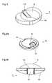
- the guide piece 32ahas a rectangular parallelepiped shape whose lower part is received in a groove 30a of the lower plate 22a sagittally oriented and the upper part is received in a groove (not visible) of the core 23a oriented frontally.
- the figure 16shows a variant of the lower plate 22 of the prosthesis according to the second embodiment, wherein the sagittal groove 30b is closed at both ends and is entirely within the contour of the articulation surface 25b to limit the movements of the guide piece 32 or 32a in the sagittal direction.
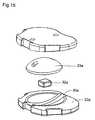
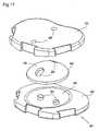
- the figures 17 and 18show an intervertebral disk prosthesis 40 according to a third embodiment of the present invention.
- the prosthesis 40comprises an upper plate 41, a lower plate 42 and a core 43.
- the plates 41, 42have respective concave articulation surfaces 44, 45 cooperating with respective convex hinge surfaces 46, 47 of the core 43.
- the upper plate 41 and the core 43are coupled by coupling means comprising, as in the second embodiment, inclined nipples 48 projecting from a peripheral portion of the articulation surface 44 of the upper plate 41 and inclined cavities
- the pins 48are located in the sagittal plane passing through the axis of the prosthesis, directed towards said axis and symmetrical to each other with respect to said axis.
- the corresponding cavities 49here have an oblong shape oriented in a sagittal direction.
- the prosthesis 40further comprises means for coupling the core 43 and the lower plate 42, constituted by inclined nipples 50 projecting from a peripheral portion of the articulation surface 45 of the lower plate 42 and corresponding inclined cavities 51 formed in the hinge surface 47 of the core 43.
- the pins 50are located in the frontal plane passing through the axis of the prosthesis, directed towards said axis and symmetrical to each other with respect to said axis.
- the corresponding cavities 49have an oblong shape oriented in a frontal direction.
- the respective clearances between the studs 48 and the cavities 49 and between the studs 50 and the cavities 51are sufficiently large to allow bending / extension or lateral inclination movements of the upper plate 41 relative to the lower plate 42 in two phases, namely a first phase during which the studs 48 move freely in the cavities 49 and a second phase during which the upper plate 41 drives the core 43 through By means of the nipples 48.
- the coupling means 50, 51guide the movement of the core 43.
- These coupling means 50, 51, with the means 48, 49further limit the axial rotation of the upper plate 41 relative to the lower plate 42.
- the present inventionhas been described above by way of example only. It will be clear to those skilled in the art that modifications can be made without departing from the scope of the invention.
- the projections 11, 28, 48could be provided on the core 4, 23, 43 rather than on the upper plate 2, 21, 41 and the corresponding cavities 12, 29, 49 formed in the upper plate 2, 21 , 41 rather than in the core 4, 23, 43.
- the rail 13 or pins 50could be provided on the core 4, 43 rather than the lower plate 3, 42 and the corresponding groove 15 or the cavities corresponding 51 formed in the lower plate 3, 42 rather than the core 4, 43.
- Another modification of the prosthesis according to the inventioncould consist in reversing the upper and lower trays.
- the first coupling means 11-12, 28-29, 48-49would be associated with the lower surface of the core, and the second coupling means 13, 15, 30-32, 50-51 on the upper surface. of the nucleus.
- the radius of curvature of the upper hinge surface of the core and the corresponding hinge surface of the upper platewould, however, remain less than the radius of curvature of the lower hinge surface of the core and the corresponding hinge surface of the plate. inferior.
Landscapes
- Health & Medical Sciences (AREA)
- Engineering & Computer Science (AREA)
- Biomedical Technology (AREA)
- Neurology (AREA)
- Orthopedic Medicine & Surgery (AREA)
- Cardiology (AREA)
- Oral & Maxillofacial Surgery (AREA)
- Transplantation (AREA)
- Heart & Thoracic Surgery (AREA)
- Vascular Medicine (AREA)
- Life Sciences & Earth Sciences (AREA)
- Animal Behavior & Ethology (AREA)
- General Health & Medical Sciences (AREA)
- Public Health (AREA)
- Veterinary Medicine (AREA)
- Prostheses (AREA)
Abstract
Description
Translated fromFrenchLa présente invention concerne une prothèse destinée à remplacer le disque intervertébral.The present invention relates to a prosthesis for replacing the intervertebral disc.
Le disque intervertébral est un disque fibrocartilagineux qui assure la liaison entre deux vertèbres adjacentes de la colonne vertébrale. L'ensemble formé par le disque intervertébral et les deux vertèbres adjacentes correspondantes est appelé « segment vertébral ».The intervertebral disk is a fibrocartilaginous disk that connects two adjacent vertebrae of the spine. The assembly formed by the intervertebral disc and the two adjacent adjacent vertebrae is called the "vertebral segment".
Les prothèses de disque intervertébral sont généralement constituées de deux plateaux dits supérieur et inférieur en regard l'un de l'autre et destinés à être fixés à deux vertèbres adjacentes respectives dites supérieure et inférieure, et d'un noyau interposé entre les deux plateaux. Les plateaux sont généralement métalliques et le noyau réalisé en métal ou en un polymère tel que le polyéthylène à haute densité. Deux types principaux de telles prothèses existent à ce jour :
- les prothèses dites non contraintes, dans lesquelles le noyau est libre par rapport aux deux plateaux et comporte des surfaces d'articulation, généralement convexes, coopérant avec des surfaces d'articulation, généralement concaves, des plateaux ;
- les prothèses dites contraintes, dans lesquelles le noyau est solidaire de l'un des deux plateaux et comporte une surface d'articulation, généralement convexe, coopérant à la manière d'une rotule avec une surface d'articulation, généralement concave, de l'autre plateau.
- the so-called unstressed prostheses, in which the core is free with respect to the two plates and comprises articulation surfaces, generally convex, cooperating with articulation surfaces, generally concave, trays;
- the prostheses called stresses, in which the core is integral with one of the two plates and comprises a hinge surface, generally convex, cooperating in the manner of a ball joint with a hinge surface, generally concave, of the other tray.
Dans le premier type de prothèse, le noyau a cinq degrés de liberté, trois en rotation et deux en translation, par rapport à un repère fixe. Lors d'un mouvement de flexion/extension (patient penché en avant/arrière respectivement) ou d'inclinaison latérale (patient penché sur le côté), le plateau supérieur s'incline par rapport au plateau inférieur en glissant sur le noyau en direction d'une extrémité de la prothèse. Ce mouvement d'inclinaison du plateau supérieur, qui peut être vu comme une combinaison d'une rotation autour d'un axe horizontal passant par le centre de gravité de l'ensemble formé par le plateau supérieur et la vertèbre supérieure et d'une translation vers l'extrémité précitée de la prothèse, entraîne une translation du noyau vers l'extrémité opposée de la prothèse, translation qui compense ainsi la translation du plateau supérieur vers la première extrémité. Lors d'un mouvement de torsion du patient, le plateau supérieur pivote par rapport au plateau inférieur dans le plan horizontal en s'articulant avec le noyau. Des moyens de couplage entre les plateaux et le noyau, tels que des plots centraux faisant saillie sur le noyau ou les plateaux et coopérant avec des cavités correspondantes formées dans les plateaux ou le noyau respectivement, sont dans certains cas prévus pour limiter l'amplitude des mouvements de la prothèse ou simplement éviter l'éjection du noyau. Des exemples de telles prothèses non contraintes sont décrits dans le
Dans le second type de prothèse, le noyau a trois degrés de liberté en rotation et aucun degré de liberté en translation. Un exemple de telles prothèses contraintes est décrit dans la demande de
Aucun de ces deux types de prothèses ne reproduit fidèlement la biomécanique naturelle du segment vertébral. Ces prothèses sont en effet fondées sur une conception linéaire de la biomécanique alors que la biomécanique naturelle du segment vertébral, plus précisément la fonction qui relie le déplacement du segment vertébral à la force appliquée, est non linéaire.None of these two types of prostheses faithfully reproduce the natural biomechanics of the vertebral segment. These prostheses are indeed based on a linear conception of biomechanics whereas the natural biomechanics of the vertebral segment, more precisely the function that links the displacement of the vertebral segment to the applied force, is nonlinear.
La présente invention vise à fournir une prothèse de disque intervertébral permettant de reproduire plus fidèlement la biomécanique naturelle du segment vertébral. A cette fin, il est proposé une prothèse de disque intervertébral telle que définie dans la revendication 1 annexée, des modes de réalisation particuliers étant définis dans les revendications dépendantes.The present invention aims to provide an intervertebral disk prosthesis for reproducing more accurately the natural biomechanics of the vertebral segment. For this purpose, there is provided an intervertebral disc prosthesis as defined in appended
D'autres caractéristiques et avantages de la présente invention apparaîtront à la lecture de la description détaillée suivante faite en référence aux dessins annexés dans lesquels :
- la
figure 1 est une vue en coupe sagittale d'une prothèse de disque intervertébral selon un premier mode de réalisation de l'invention, en position neutre ; - les
figures 2 et3 sont des vues en perspective montrant respectivement un plateau supérieur et un plateau inférieur de la prothèse selon le premier mode de réalisation ; - les
figures 4a et 4b sont respectivement une vue en perspective de dessus et une vue arrière d'un noyau de la prothèse selon le premier mode de réalisation ; - la
figure 5a est une vue en coupe sagittale schématique de la prothèse selon le premier mode de réalisation en train d'effectuer une première phase d'un mouvement de flexion ; - la
figure 5b est une vue en coupe sagittale schématique de la prothèse selon le premier mode de réalisation dans une position correspondant à la fin de la première phase du mouvement de flexion ; - les
figures 6 et 7 sont des vues en coupe sagittale schématiques montrant la prothèse selon le premier mode de réalisation en train d'effectuer une seconde phase d'un mouvement de flexion, respectivement d'extension ; - la
figure 8 est une vue en perspective éclatée, partiellement coupée, d'une prothèse de disque intervertébral selon un second mode de réalisation de l'invention ; - les
figures 9 et 10 sont des vues en coupe sagittale et frontale, respectivement, montrant la prothèse selon le second mode de réalisation en position neutre ; - les
figures 11 et 12 sont des vues en coupe sagittale schématiques montrant la prothèse selon le second mode de réalisation en train d'effectuer une seconde phase d'un mouvement de flexion, respectivement d'extension ; - les
figures 13 et 14 sont des vues en coupe frontale schématiques montrant la prothèse selon le second mode de réalisation en train d'effectuer une seconde phase d'un mouvement d'inclinaison latérale vers la droite, respectivement vers la gauche ; - la
figure 15 est une vue en perspective éclatée d'une variante de la prothèse selon le second mode de réalisation ; - la
figure 16 est une vue en perspective de dessus d'un plateau inférieur faisant partie d'une autre variante de la prothèse selon le second mode de réalisation, - les
figures 17 et18 sont des vues en perspective de dessus et de dessous respectivement, montrant une prothèse de disque intervertébral selon un troisième mode de réalisation de l'invention ; et - la
figure 19 montre la courbe du déplacement naturel d'une vertèbre en fonction de la force appliquée à celle-ci.
- the
figure 1 is a sagittal sectional view of an intervertebral disk prosthesis according to a first embodiment of the invention, in a neutral position; - the
figures 2 and3 are perspective views respectively showing an upper plate and a lower plate of the prosthesis according to the first embodiment; - the
Figures 4a and 4b are respectively a perspective view from above and a rear view of a core of the prosthesis according to the first embodiment; - the
figure 5a is a schematic sagittal sectional view of the prosthesis according to the first embodiment performing a first phase of a flexion movement; - the
figure 5b is a schematic sagittal sectional view of the prosthesis according to the first embodiment in a position corresponding to the end of the first phase of the flexion movement; - the
Figures 6 and 7 are schematic sagittal sectional views showing the prosthesis according to the first embodiment performing a second phase of a flexion or extension movement; - the
figure 8 is an exploded perspective view, partially cut away, of an intervertebral disk prosthesis according to a second embodiment of the invention; - the
Figures 9 and 10 are sagittal and frontal sectional views, respectively, showing the prosthesis according to the second embodiment in the neutral position; - the
Figures 11 and 12 are schematic sagittal sectional views showing the prosthesis according to the second embodiment performing a second phase of a flexion or extension movement respectively; - the
Figures 13 and 14 are schematic cross-sectional views showing the prosthesis according to the second embodiment performing a second phase of a lateral inclination movement to the right, respectively to the left; - the
figure 15 is an exploded perspective view of a variant of the prosthesis according to the second embodiment; - the
figure 16 is a perspective view from above of a lower plate forming part of another variant of the prosthesis according to the second embodiment, - the
figures 17 and18 are perspective views from above and below respectively, showing an intervertebral disc prosthesis according to a third embodiment of the invention; and - the
figure 19 shows the curve of the natural displacement of a vertebra according to the force applied to it.
En référence aux
Le noyau 4 est couplé aux plateaux 2, 3 respectivement par des premiers et seconds moyens de couplage. Les premiers moyens de couplage comprennent une quille 11 faisant saillie sur une partie périphérique antérieure de la face inférieure du plateau supérieur 2 et une cavité 12 formée dans le noyau 4 et débouchant sur la surface d'articulation 9 de ce dernier, la cavité 12 recevant la quille 11. Par « partie périphérique » on entend une partie non traversée par l'axe A de la prothèse. La quille 11 est par ailleurs située dans le plan sagittal passant par l'axe A, et est inclinée par rapport au plateau supérieur 2 et dirigée vers ledit axe A. La quille 11 peut être formée d'un seul tenant avec le plateau supérieur 2 ou fixée à celui-ci par exemple par soudage. La cavité 12 a sensiblement la même forme, par exemple tronconique, que la quille 11, mais sa section est plus grande que celle de la quille 11 de façon à autoriser un débattement de la quille 11 et donc du plateau supérieur 2 par rapport au noyau 4 dans les plans sagittal, frontal et coronal. Les seconds moyens de couplage comprennent un rail 13 formé d'un seul tenant avec le plateau inférieur 3 ou fixé à celui-ci par exemple par soudage et s'étendant dans une direction sagittale sur la surface d'articulation 8 dudit plateau inférieur 3. Ce rail 13, situé dans la partie postérieure de la prothèse, définit une surface d'appui pentue 14 reliant le sommet du rail 13, au niveau du bord postérieur du plateau inférieur 3, à la partie centrale de la surface d'articulation 8 du plateau 3. Ce rail 13 coopère avec une rainure 15 de forme correspondante, comprenant elle aussi une surface d'appui pentue 16, formée dans la surface d'articulation inférieure 10 du noyau 4. La rainure 15 a une section plus large que celle du rail 13, de façon à autoriser un débattement en rotation axiale, c'est-à-dire autour de l'axe A, du noyau 4 par rapport au plateau inférieur 3 (torsion) ainsi qu'en inclinaison latérale.The
Conformément à l'invention, les mouvements d'inclinaison du plateau supérieur 2 de la prothèse par rapport au plateau inférieur 3 dans le plan sagittal (flexion / extension) ou frontal (inclinaison latérale) se décomposent en deux phases :
- une première phase au cours de laquelle le
plateau supérieur 2 glisse sur le noyau 4, la quille 11 se déplaçant librement dans la cavité 12 ; et - une seconde phase, qui débute juste après que la quille 11 est entrée en contact avec la paroi interne de la cavité 12 (cf.
figure 5b ), au cours de laquelle leplateau supérieur 2 entraîne avec lui le noyau 4 par l'intermédiaire de la quille 11 (cf.figure 6 : prothèse en flexion ;figure 7 : prothèse en extension).
- a first phase during which the
upper plate 2 slides on thecore 4, thekeel 11 moving freely in thecavity 12; and - a second phase, which starts just after the
keel 11 has come into contact with the inner wall of the cavity 12 (cf.figure 5b ), during which theupper plate 2 carries with it thecore 4 via the keel 11 (cf.figure 6 : flexural prosthesis;figure 7 : prosthesis in extension).
Lors de la première phase, une faible force appliquée à l'ensemble plateau supérieur 2 - vertèbre supérieure suffit à entraîner un déplacement d'inclinaison important de cet ensemble. Dans la seconde phase, un supplément de force bien plus élevé doit être appliqué pour obtenir la même amplitude de déplacement que dans la première phase, du fait que le plateau supérieur 2 entraîne le noyau 4 et doit donc exercer un effort plus important. Ceci est conforme à la biomécanique naturelle du segment vertébral. En effet, comme représenté à la
Un autre avantage de ce mouvement en deux phases du plateau supérieur 2 par rapport au plateau inférieur 3 est qu'il permet de contrôler le déplacement du noyau 4, et ainsi limiter les contraintes, en particulier les hyper-pressions surfaciques ou ponctuelles et les hypo-pressions, pouvant s'exercer sur le système articulaire postérieur, du fait que ce noyau 4 est rendu solidaire du plateau supérieur 2 lors de la seconde phase.Another advantage of this two-phase movement of the
On notera de plus que les moyens de couplage 11, 12, 13, 15 de la prothèse selon l'invention n'autorisent les mouvements de torsion (rotation axiale du plateau supérieur 2 par rapport au plateau inférieur 3) que dans des limites déterminées. Ceci contribue également à protéger le système articulaire postérieur.It will be further noted that the coupling means 11, 12, 13, 15 of the prosthesis according to the invention allow torsional movements (axial rotation of the
Outre leur fonction de limitation de la rotation axiale du noyau 4 par rapport au plateau inférieur 3, le rail 13 et la rainure correspondante 15 coopèrent lors des mouvements de flexion pour soulever légèrement le centre de gravité du noyau 4, à l'instar du mouvement physiologique, par un glissement de la surface d'appui pentue 16 de la rainure 15 sur la surface d'appui pentue 14 du rail 13 (cf.
Par ailleurs, du fait que les surfaces d'articulation congruentes 6, 9 ont un rayon de courbure R1 inférieur au rayon de courbure R2 des surfaces d'articulation congruentes 8, 10, la composante de rotation des mouvements d'inclinaison du plateau supérieur 2 est privilégiée par rapport à la composante de translation.On the other hand, because the congruent articulation surfaces 6, 9 have a radius of curvature R1 smaller than the radius of curvature R2 of the congruent articulation surfaces 8, 10, the rotational component of the inclination movements of the
La prothèse selon la présente invention présente en outre l'avantage de limiter les risques d'éjection du noyau 4, grâce notamment à la coopération entre la quille 11 et la cavité 12.The prosthesis according to the present invention also has the advantage of limiting the risks of ejection of the
En référence aux
Le noyau 23 et le plateau inférieur 22 sont couplés par des seconds moyens de couplage comprenant une première rainure à section rectangulaire 30 formée dans la surface d'articulation 25 du plateau inférieur 22 et s'étendant dans une direction sagittale, une seconde rainure à section rectangulaire 31 formée dans la surface d'articulation 27 du noyau 23 et s'étendant dans une direction frontale, et une pièce intermédiaire mobile, de guidage, en forme de T 32 coopérant avec les deux rainures 30, 31. Plus précisément, la branche verticale 33 de la pièce de guidage 32, plus courte que la branche horizontale 34, est guidée dans la première rainure 30 tandis que la branche horizontale 34 est guidée dans la seconde rainure 31. La première rainure 30 est plus large que la branche verticale 33 de la pièce de guidage 32, de façon à définir un jeu 30' (visible uniquement sur la
Les mouvements de flexion, extension et inclinaison latérale de la prothèse 20 sont similaires à ceux de la prothèse 1, c'est-à-dire qu'ils s'effectuent en deux phases, à savoir une première phase où le mouvement entre le plateau supérieur 21 et le noyau 23 est non contraint, les tétons 28 se déplaçant librement dans les cavités 29, et une seconde phase où les tétons 28, en butée contre la paroi interne de leurs cavités respectives 29, poussent le noyau 23 le rendant ainsi solidaire du plateau supérieur 21 (cf.
La prothèse 20 selon ce second mode de réalisation présente l'avantage, par rapport à la prothèse 1 selon le premier mode de réalisation, de mieux contrôler les mouvements de la prothèse, et donc de réduire les contraintes exercées sur le système articulaire postérieur, en limitant les mouvements couplés (combinaisons de mouvements de flexion/extension, d'inclinaison latérale et de rotation axiale), ceci grâce à la pièce de guidage 32 et aux rainures associées 30, 31 qui guident les mouvements de la prothèse.The
Dans une variante de réalisation de ce second mode de réalisation, montrée à la
La
Les
La prothèse 40 comporte en outre des moyens de couplage du noyau 43 et du plateau inférieur 42, constitués par des tétons inclinés 50 faisant saillie sur une partie périphérique de la surface d'articulation 45 du plateau inférieur 42 et des cavités inclinées correspondantes 51 formées dans la surface d'articulation 47 du noyau 43. Les tétons 50 sont situés dans le plan frontal passant par l'axe de la prothèse, dirigés vers ledit axe et symétriques l'un de l'autre par rapport audit axe. Les cavités correspondantes 49 ont une forme oblongue orientée dans une direction frontale.The
Les jeux respectifs entre les tétons 48 et les cavités 49 et entre les tétons 50 et les cavités 51 sont suffisamment grands pour permettre des mouvements de flexion/extension ou d'inclinaison latérale du plateau supérieur 41 par rapport au plateau inférieur 42 en deux phases, à savoir une première phase pendant laquelle les tétons 48 se déplacent librement dans les cavités 49 et une seconde phase pendant laquelle le plateau supérieur 41 entraîne le noyau 43 par l'intermédiaire des tétons 48. Pendant ces mouvements d'inclinaison du plateau supérieur 41, les moyens de couplage 50, 51 guident les mouvement du noyau 43. Ces moyens de couplage 50, 51, avec les moyens 48, 49, limitent en outre la rotation axiale du plateau supérieur 41 par rapport au plateau inférieur 42.The respective clearances between the
La présente invention a été décrite ci-dessus à titre d'exemple uniquement. Il apparaîtra clairement à l'homme du métier que des modifications peuvent être faites sans sortir du cadre de l'invention. Par exemple, les parties saillantes 11, 28, 48 pourraient être prévues sur le noyau 4, 23, 43 plutôt que sur le plateau supérieur 2, 21, 41 et les cavités correspondantes 12, 29, 49 formées dans le plateau supérieur 2, 21, 41 plutôt que dans le noyau 4, 23, 43. De façon comparable, le rail 13 ou les tétons 50 pourraient être prévus sur le noyau 4, 43 plutôt que sur le plateau inférieur 3, 42 et la rainure correspondante 15 ou les cavités correspondantes 51 formées dans le plateau inférieur 3, 42 plutôt que dans le noyau 4, 43. Une autre modification de la prothèse selon l'invention pourrait consister à inverser les plateaux supérieur et inférieur. Dans ce cas, les premiers moyens de couplage 11-12, 28-29, 48-49 seraient associés à la surface inférieure du noyau, et les seconds moyens de couplage 13, 15, 30-32, 50-51 à la surface supérieure du noyau. Le rayon de courbure de la surface d'articulation supérieure du noyau et de la surface d'articulation correspondante du plateau supérieur resterait toutefois inférieur au rayon de courbure de la surface d'articulation inférieure du noyau et de la surface d'articulation correspondante du plateau inférieur.The present invention has been described above by way of example only. It will be clear to those skilled in the art that modifications can be made without departing from the scope of the invention. For example, the
Claims (17)
- Intervertebral disk prosthesis comprising:- first and second parts (2, 3) intended to be attached respectively to two adjacent vertebrae,- an intermediate part (4) inserted between the first and second parts (2, 3) and comprising articular surfaces (9, 10) that cooperate with respective articular surfaces (6, 8) of the first and second parts (2, 3), and- means (11, 12) for coupling the first part (2) and the intermediate part (4),characterised in that the coupling means (11, 12) are arranged to leave the intermediate part (4) free relative to the first part (2) during a first phase of a tilting movement of the first part (2) relative to the second part (3), such that the intermediate part (4) is displaced toward an end (E2) of the prosthesis that is opposite to an end (E1) toward which the first part (2) is displaced by tilting relative to the second part (3), and to drive the intermediate part (4) with the first part (2) during a second phase of the tilting movement.
- Intervertebral disk prosthesis according to claim 1,characterised in that said coupling means comprise at least one projecting portion (11) provided on one of the first part (2) and intermediate part (4) and at least one cavity (12) formed in the other of the first part (2) and intermediate part (4), whereby this cavity (12) receives the projecting portion (11) and has a larger section than that of the projecting portion (11).
- Intervertebral disk prosthesis according to claim 2,characterised in that said coupling means comprise a single projecting portion (11) provided on a peripheral part of the first part (2) or the intermediate part (4) and in a sagittal plane.
- Intervertebral disk prosthesis according to claim 2,characterised in that said coupling means comprise first and second projecting portions (28; 48) provided on the first part (21; 41) or the intermediate part (23; 43) and located in a sagittal plane, on both sides of the axis of the prosthesis, and first and second corresponding cavities (29; 49) formed in the intermediate part (23; 43) or the first part (21; 41) respectively.
- Intervertebral disk prosthesis according to any of claims 1 to 4,characterised by further comprising means (13, 15) for coupling the intermediate part (4) and the second part (3), whereby these coupling means limit the relative movements in axial rotation of said intermediate part (4) and second part (3).
- Intervertebral disk prosthesis according to claim 5,characterised in that said means for coupling the intermediate part (4) and the second part (3) comprise a rail (13) extending in a sagittal direction on one of the second part (3) and intermediate part (4) and a groove (15) formed in the other of the second part (3) and intermediate part (4) and cooperating with this rail (13).
- Intervertebral disk prosthesis according to claim 6,characterised in that the rail (13) and the groove (15) define respective inclined support surfaces (14, 16) that cooperate during flexion movements of the prosthesis to slightly raise the center of gravity of the intermediate part (4).
- Intervertebral disk prosthesis according to claim 5,characterised in that said means for coupling the intermediate part (23) and the second part (22) comprise a first groove (30; 30a; 30b) formed in the second part (22) and oriented in a sagittal direction, a second groove (31) formed in the intermediate part (23) and oriented in a frontal direction, and a mobile guide part (32; 32a) cooperating with the first and second grooves (30; 30a; 30b, 31).
- Intervertebral disk prosthesis according to claim 8,characterised in that a clearance (30') exists between the guide part (32) and at least one of the first and second grooves (30, 31), allowing axial rotation play of the intermediate part (23) relative to the second part (22).
- Intervertebral disk prosthesis according to claim 5,characterised in that said means for coupling the intermediate part (43) and the second part (42) comprise first and second studs (50) provided on the second part (42) or the intermediate part (43) and located in a frontal plane, on both sides of the axis of the prosthesis, and third and fourth cavities (51) formed in the intermediate part (43) or the second part (42), respectively, and receiving the studs (50).
- Intervertebral disk prosthesis according to any of claims 1 to 10,characterised in that the first phase of the tilting movement corresponds to about 40 to 60% of the maximum tilting angle of the first part (2) relative to the second part (3), and the second phase corresponds to the remaining 60 to 40%.
- Intervertebral disk prosthesis according to any of claims 1 to 11,characterised in that the first phase of the tilting movement corresponds to an angular tilting range of the first part (2) relative to the second part (3) of about 4 to 8°, and the second phase of the tilting movement corresponds to an angular tilting range of the first part (2) relative to the second part (3) of about 3 to 7°.
- Intervertebral disk prosthesis according to any of claims 1 to 11,characterised in that the first phase of the tilting movement corresponds to an angular tilting range of the first part (2) relative to the second part (3) of about 5 to 7°, and the second phase of the tilting movement corresponds to an angular tilting range of the first part (2) relative to the second part (3) of about 4 to 6°.
- Intervertebral disk prosthesis according to any of claims 1 to 13,characterised in that said articular surfaces (9, 10) of the intermediate part (4) are convex, and said respective articular surfaces (6, 8) of the first and second parts (2, 3) are concave.
- Intervertebral disk prosthesis according to any of claims 1 to 14,characterised in that the articular surface (6) of the first part (2) and the corresponding articular surface (9) of the intermediate part (4) are spherical portions of radius R1, andin that the articular surface (8) of the second part (3) and the corresponding articular surface (10) of the intermediate part (4) are spherical portions of radius R2.
- Intervertebral disk prosthesis according to claim 15,characterised in that the radius R1 is less than the radius R2.
- Intervertebral disk prosthesis according to any of claims 1 to 16,characterised in that the first part (2; 21) is an upper part, and the second part (3; 22) is a lower part.
Priority Applications (4)
| Application Number | Priority Date | Filing Date | Title |
|---|---|---|---|
| ES05008271TES2387392T3 (en) | 2005-04-15 | 2005-04-15 | Intervertebral disc prosthesis |
| EP05008271AEP1712207B1 (en) | 2005-04-15 | 2005-04-15 | Intervertebral disc |
| AT05008271TATE556676T1 (en) | 2005-04-15 | 2005-04-15 | DISC PROSTHESIS |
| US11/183,827US7537615B2 (en) | 2005-04-15 | 2005-07-19 | Intervertebral disk prosthesis |
Applications Claiming Priority (1)
| Application Number | Priority Date | Filing Date | Title |
|---|---|---|---|
| EP05008271AEP1712207B1 (en) | 2005-04-15 | 2005-04-15 | Intervertebral disc |
Publications (2)
| Publication Number | Publication Date |
|---|---|
| EP1712207A1 EP1712207A1 (en) | 2006-10-18 |
| EP1712207B1true EP1712207B1 (en) | 2012-05-09 |
Family
ID=34935224
Family Applications (1)
| Application Number | Title | Priority Date | Filing Date |
|---|---|---|---|
| EP05008271AExpired - LifetimeEP1712207B1 (en) | 2005-04-15 | 2005-04-15 | Intervertebral disc |
Country Status (4)
| Country | Link |
|---|---|
| US (1) | US7537615B2 (en) |
| EP (1) | EP1712207B1 (en) |
| AT (1) | ATE556676T1 (en) |
| ES (1) | ES2387392T3 (en) |
Families Citing this family (54)
| Publication number | Priority date | Publication date | Assignee | Title |
|---|---|---|---|---|
| FR2824261B1 (en) | 2001-05-04 | 2004-05-28 | Ldr Medical | INTERVERTEBRAL DISC PROSTHESIS AND IMPLEMENTATION METHOD AND TOOLS |
| FR2831049B1 (en) | 2001-10-18 | 2004-08-13 | Ldr Medical | PLATE FOR OSTEOSYNTHESIS DEVICE AND PRE-ASSEMBLY METHOD |
| FR2831048B1 (en) | 2001-10-18 | 2004-09-17 | Ldr Medical | PROGRESSIVE APPROACH OSTEOSYNTHESIS DEVICE AND PRE-ASSEMBLY PROCESS |
| CN1304618C (en)* | 2002-04-05 | 2007-03-14 | 新日本制铁株式会社 | Pealite based rail excellent in wear resistance and ductility and method for production thereof |
| FR2846550B1 (en) | 2002-11-05 | 2006-01-13 | Ldr Medical | INTERVERTEBRAL DISC PROSTHESIS |
| US7448734B2 (en)* | 2004-01-21 | 2008-11-11 | Silverbrook Research Pty Ltd | Inkjet printer cartridge with pagewidth printhead |
| EP2113227B1 (en) | 2004-02-04 | 2015-07-29 | LDR Medical | Intervertebral disc prosthesis |
| FR2865629B1 (en) | 2004-02-04 | 2007-01-26 | Ldr Medical | INTERVERTEBRAL DISC PROSTHESIS |
| FR2869528B1 (en)* | 2004-04-28 | 2007-02-02 | Ldr Medical | INTERVERTEBRAL DISC PROSTHESIS |
| FR2879436B1 (en) | 2004-12-22 | 2007-03-09 | Ldr Medical | INTERVERTEBRAL DISC PROSTHESIS |
| FR2887762B1 (en) | 2005-06-29 | 2007-10-12 | Ldr Medical Soc Par Actions Si | INTERVERTEBRAL DISC PROSTHESIS INSERTION INSTRUMENTATION BETWEEN VERTEBRATES |
| FR2891135B1 (en) | 2005-09-23 | 2008-09-12 | Ldr Medical Sarl | INTERVERTEBRAL DISC PROSTHESIS |
| FR2893838B1 (en) | 2005-11-30 | 2008-08-08 | Ldr Medical Soc Par Actions Si | PROSTHESIS OF INTERVERTEBRAL DISC AND INSTRUMENTATION OF INSERTION OF THE PROSTHESIS BETWEEN VERTEBRATES |
| US20070173942A1 (en)* | 2006-01-26 | 2007-07-26 | Sdgi Holdings, Inc. | Intervertebral prosthetic disc |
| FR2898487B1 (en)* | 2006-03-14 | 2008-11-14 | Spineart Sa Sa | PROSTHETICS OF INTERVERTEBRAL DISCS |
| US8043379B2 (en)* | 2006-04-21 | 2011-10-25 | Depuy Spine, Inc. | Disc prosthesis having remote flexion/extension center of rotation |
| US8029574B2 (en) | 2006-11-07 | 2011-10-04 | Biomedflex Llc | Prosthetic knee joint |
| US8308812B2 (en) | 2006-11-07 | 2012-11-13 | Biomedflex, Llc | Prosthetic joint assembly and joint member therefor |
| WO2008058205A1 (en) | 2006-11-07 | 2008-05-15 | Biomedflex, Llc | Medical implants |
| US9005307B2 (en) | 2006-11-07 | 2015-04-14 | Biomedflex, Llc | Prosthetic ball-and-socket joint |
| US8070823B2 (en) | 2006-11-07 | 2011-12-06 | Biomedflex Llc | Prosthetic ball-and-socket joint |
| US7914580B2 (en)* | 2006-11-07 | 2011-03-29 | Biomedflex Llc | Prosthetic ball-and-socket joint |
| US7905919B2 (en) | 2006-11-07 | 2011-03-15 | Biomedflex Llc | Prosthetic joint |
| US8512413B2 (en) | 2006-11-07 | 2013-08-20 | Biomedflex, Llc | Prosthetic knee joint |
| US20110166671A1 (en) | 2006-11-07 | 2011-07-07 | Kellar Franz W | Prosthetic joint |
| US9867640B2 (en) | 2006-12-07 | 2018-01-16 | Nexus Spine, LLC | Press-on pedicle screw assembly |
| WO2008098228A2 (en) | 2007-02-09 | 2008-08-14 | Diamicron, Inc. | Multi-lobe artificial spine joint |
| US8308801B2 (en)* | 2007-02-12 | 2012-11-13 | Brigham Young University | Spinal implant |
| US9314346B2 (en)* | 2007-02-12 | 2016-04-19 | Brigham Young University | Spinal implant |
| US8465546B2 (en) | 2007-02-16 | 2013-06-18 | Ldr Medical | Intervertebral disc prosthesis insertion assemblies |
| US9289310B2 (en) | 2007-03-10 | 2016-03-22 | Spinesmith Partners, L.P. | Artificial disc with post and modular collar |
| US9358121B2 (en)* | 2007-03-10 | 2016-06-07 | Spinesmith Partners, L.P. | Artificial disc with unique articulating geometry and associated methods |
| US10335288B2 (en) | 2007-03-10 | 2019-07-02 | Spinesmith Partners, L.P. | Surgical implant secured by pegs and associated methods |
| FR2916956B1 (en) | 2007-06-08 | 2012-12-14 | Ldr Medical | INTERSOMATIC CAGE, INTERVERTEBRAL PROSTHESIS, ANCHORING DEVICE AND IMPLANTATION INSTRUMENTATION |
| US8057547B2 (en)* | 2007-06-12 | 2011-11-15 | Kinetic Spine Technologies Inc. | Articulating intervertebral disc prosthesis |
| WO2008151426A1 (en)* | 2007-06-12 | 2008-12-18 | Kinetic Spine Technologies Inc. | Artificial intervertebral disc |
| US8956412B2 (en)* | 2007-06-22 | 2015-02-17 | Axiomed, LLC | Artificial disc |
| US20090093882A1 (en)* | 2007-10-09 | 2009-04-09 | Oh Younghoon | Sliding interbody device |
| US8894687B2 (en) | 2011-04-25 | 2014-11-25 | Nexus Spine, L.L.C. | Coupling system for surgical construct |
| US8083796B1 (en) | 2008-02-29 | 2011-12-27 | Nuvasive, Inc. | Implants and methods for spinal fusion |
| DE102008032691A1 (en)* | 2008-07-03 | 2010-01-07 | Aesculap Ag | Intervertebral disc prosthesis system |
| CA2743721A1 (en)* | 2009-02-19 | 2010-08-26 | Anton E. Bowden | Compliant dynamic spinal implant |
| WO2010096829A2 (en) | 2009-02-23 | 2010-08-26 | Crocker Spinal, L.L.C. | Press-on link for surgical screws |
| DE102009011648A1 (en)* | 2009-03-04 | 2010-09-09 | Advanced Medical Technologies Ag | Implant system with support elements |
| US9157497B1 (en) | 2009-10-30 | 2015-10-13 | Brigham Young University | Lamina emergent torsional joint and related methods |
| US8277509B2 (en)* | 2009-12-07 | 2012-10-02 | Globus Medical, Inc. | Transforaminal prosthetic spinal disc apparatus |
| US9358122B2 (en) | 2011-01-07 | 2016-06-07 | K2M, Inc. | Interbody spacer |
| US8998991B2 (en)* | 2011-02-23 | 2015-04-07 | Globus Medical, Inc. | Six degree spine stabilization devices and methods |
| JP5663674B2 (en) | 2011-03-11 | 2015-02-04 | エフビーシー デバイス エーピーエス | Spine implant, pretreatment instrument and method of use |
| US8480743B2 (en)* | 2011-03-25 | 2013-07-09 | Vicente Vanaclocha Vanaclocha | Universal disc prosthesis |
| WO2012177412A2 (en) | 2011-06-07 | 2012-12-27 | Brigham Young University | Serpentine spinal stability device and associated methods |
| US9642651B2 (en) | 2014-06-12 | 2017-05-09 | Brigham Young University | Inverted serpentine spinal stability device and associated methods |
| US11452618B2 (en) | 2019-09-23 | 2022-09-27 | Dimicron, Inc | Spinal artificial disc removal tool |
| CN119868020B (en)* | 2025-02-06 | 2025-10-03 | 首都医科大学宣武医院 | A lumbar intervertebral disc prosthesis |
Family Cites Families (8)
| Publication number | Priority date | Publication date | Assignee | Title |
|---|---|---|---|---|
| FR2659226B1 (en) | 1990-03-07 | 1992-05-29 | Jbs Sa | PROSTHESIS FOR INTERVERTEBRAL DISCS AND ITS IMPLEMENTATION INSTRUMENTS. |
| DE4208116C2 (en) | 1992-03-13 | 1995-08-03 | Link Waldemar Gmbh Co | Intervertebral disc prosthesis |
| FR2824261B1 (en)* | 2001-05-04 | 2004-05-28 | Ldr Medical | INTERVERTEBRAL DISC PROSTHESIS AND IMPLEMENTATION METHOD AND TOOLS |
| US6793678B2 (en) | 2002-06-27 | 2004-09-21 | Depuy Acromed, Inc. | Prosthetic intervertebral motion disc having dampening |
| AU2003226586A1 (en)* | 2002-09-19 | 2004-04-08 | Malan De Villiers | Intervertebral prosthesis |
| FR2846550B1 (en) | 2002-11-05 | 2006-01-13 | Ldr Medical | INTERVERTEBRAL DISC PROSTHESIS |
| US7582115B2 (en)* | 2004-09-30 | 2009-09-01 | Helmut Weber | Intervertebral prosthesis |
| US7566346B2 (en)* | 2004-10-29 | 2009-07-28 | X-Spine Systems, Inc. | Prosthetic implant and method |
- 2005
- 2005-04-15EPEP05008271Apatent/EP1712207B1/ennot_activeExpired - Lifetime
- 2005-04-15ESES05008271Tpatent/ES2387392T3/ennot_activeExpired - Lifetime
- 2005-04-15ATAT05008271Tpatent/ATE556676T1/enactive
- 2005-07-19USUS11/183,827patent/US7537615B2/ennot_activeExpired - Fee Related
Also Published As
| Publication number | Publication date |
|---|---|
| EP1712207A1 (en) | 2006-10-18 |
| US7537615B2 (en) | 2009-05-26 |
| ATE556676T1 (en) | 2012-05-15 |
| ES2387392T3 (en) | 2012-09-21 |
| US20060235526A1 (en) | 2006-10-19 |
Similar Documents
| Publication | Publication Date | Title |
|---|---|---|
| EP1712207B1 (en) | Intervertebral disc | |
| EP2303195B1 (en) | Total knee prosthesis | |
| EP1354571B1 (en) | Total knee prothesis | |
| EP1981443B1 (en) | Anatomic intervertebral spacer | |
| FR3132204A1 (en) | IMPROVED ANKLE PROSTHESIS | |
| EP0950387A1 (en) | Knee prosthesis | |
| CA2354165A1 (en) | Intervertebral disc prosthesis with contact blocks | |
| EP1997449A2 (en) | Device and assembly for rear dynamic guidance of the spine and spine treatment system comprising such a device | |
| EP0749734B1 (en) | Total knee joint prosthesis | |
| EP0472475A2 (en) | Bicondylar knee prosthesis | |
| FR2776919A1 (en) | TOTAL KNEE PROSTHESIS WITH HINGE | |
| WO1996000538A1 (en) | Prosthetic knee joint, particularly a single-compartment knee prosthesis or a kneecap prosthesis | |
| EP2572677A1 (en) | Hinge type knee prosthesis | |
| FR2758456A1 (en) | Posterio-stabilised knee joint prosthesis | |
| WO2015018854A1 (en) | Knee prosthesis with ceramic-on-ceramic friction coupling and movable ceramic plate | |
| WO2003007841A2 (en) | Intervertebral implant for cervical vertebrae | |
| EP0788333B1 (en) | Knee joint prosthesis | |
| FR2981562A1 (en) | INTERVERTEBRAL DISC PROSTHESIS | |
| FR2913591A1 (en) | Posterior stabilized type complete knee prosthesis, has femoral condyles of femoral implant and glenoid surfaces corresponding to intermediate plateau are such that medial lobe engages in round cavity during flexion movement of joint | |
| FR2707871A1 (en) | Bicondylar knee prosthesis of the sliding type | |
| FR2628316A1 (en) | Whole knee prosthesis - has one piece implanted at end of femur, other at end of tibia articulating around cross member of T=piece | |
| FR2844704A1 (en) | Mobile plate knee prosthesis comprises tibial base fixed on tibia upper end, intermediate friction plate received on tibia base having projection engaged in plate opening and femoral element anchored at femur lower end | |
| EP1706076B1 (en) | Intervertebral discal prosthesis | |
| FR2842411A1 (en) | Total knee prosthesis has intermediate plate able to pivot relative to tibial component by means of engaging stud and cavity | |
| FR2893497A1 (en) | Complete knee joint prosthesis, has intermediate plate comprising boss projecting from base of cavity and conformed for being received in adjusted manner with possibility of rotation in recess that is provided in stud of tibial element |
Legal Events
| Date | Code | Title | Description |
|---|---|---|---|
| PUAI | Public reference made under article 153(3) epc to a published international application that has entered the european phase | Free format text:ORIGINAL CODE: 0009012 | |
| AK | Designated contracting states | Kind code of ref document:A1 Designated state(s):AT BE BG CH CY CZ DE DK EE ES FI FR GB GR HU IE IS IT LI LT LU MC NL PL PT RO SE SI SK TR | |
| AX | Request for extension of the european patent | Extension state:AL BA HR LV MK YU | |
| 17P | Request for examination filed | Effective date:20070315 | |
| AKX | Designation fees paid | Designated state(s):AT BE BG CH CY CZ DE DK EE ES FI FR GB GR HU IE IS IT LI LT LU MC NL PL PT RO SE SI SK TR | |
| RAP1 | Party data changed (applicant data changed or rights of an application transferred) | Owner name:EDEN SPINE EUROPE SA | |
| 17Q | First examination report despatched | Effective date:20110704 | |
| GRAP | Despatch of communication of intention to grant a patent | Free format text:ORIGINAL CODE: EPIDOSNIGR1 | |
| GRAS | Grant fee paid | Free format text:ORIGINAL CODE: EPIDOSNIGR3 | |
| GRAA | (expected) grant | Free format text:ORIGINAL CODE: 0009210 | |
| AK | Designated contracting states | Kind code of ref document:B1 Designated state(s):AT BE BG CH CY CZ DE DK EE ES FI FR GB GR HU IE IS IT LI LT LU MC NL PL PT RO SE SI SK TR | |
| REG | Reference to a national code | Ref country code:GB Ref legal event code:FG4D Free format text:NOT ENGLISH | |
| REG | Reference to a national code | Ref country code:CH Ref legal event code:EP Ref country code:AT Ref legal event code:REF Ref document number:556676 Country of ref document:AT Kind code of ref document:T Effective date:20120515 | |
| REG | Reference to a national code | Ref country code:IE Ref legal event code:FG4D Free format text:LANGUAGE OF EP DOCUMENT: FRENCH | |
| REG | Reference to a national code | Ref country code:DE Ref legal event code:R096 Ref document number:602005034064 Country of ref document:DE Effective date:20120705 | |
| REG | Reference to a national code | Ref country code:NL Ref legal event code:VDEP Effective date:20120509 | |
| RAP2 | Party data changed (patent owner data changed or rights of a patent transferred) | Owner name:EDEN SPINE EUROPE SA | |
| REG | Reference to a national code | Ref country code:ES Ref legal event code:FG2A Ref document number:2387392 Country of ref document:ES Kind code of ref document:T3 Effective date:20120921 | |
| REG | Reference to a national code | Ref country code:LT Ref legal event code:MG4D Effective date:20120509 | |
| PG25 | Lapsed in a contracting state [announced via postgrant information from national office to epo] | Ref country code:FI Free format text:LAPSE BECAUSE OF FAILURE TO SUBMIT A TRANSLATION OF THE DESCRIPTION OR TO PAY THE FEE WITHIN THE PRESCRIBED TIME-LIMIT Effective date:20120509 Ref country code:LT Free format text:LAPSE BECAUSE OF FAILURE TO SUBMIT A TRANSLATION OF THE DESCRIPTION OR TO PAY THE FEE WITHIN THE PRESCRIBED TIME-LIMIT Effective date:20120509 Ref country code:PL Free format text:LAPSE BECAUSE OF FAILURE TO SUBMIT A TRANSLATION OF THE DESCRIPTION OR TO PAY THE FEE WITHIN THE PRESCRIBED TIME-LIMIT Effective date:20120509 Ref country code:CY Free format text:LAPSE BECAUSE OF FAILURE TO SUBMIT A TRANSLATION OF THE DESCRIPTION OR TO PAY THE FEE WITHIN THE PRESCRIBED TIME-LIMIT Effective date:20120509 Ref country code:SE Free format text:LAPSE BECAUSE OF FAILURE TO SUBMIT A TRANSLATION OF THE DESCRIPTION OR TO PAY THE FEE WITHIN THE PRESCRIBED TIME-LIMIT Effective date:20120509 Ref country code:IS Free format text:LAPSE BECAUSE OF FAILURE TO SUBMIT A TRANSLATION OF THE DESCRIPTION OR TO PAY THE FEE WITHIN THE PRESCRIBED TIME-LIMIT Effective date:20120909 | |
| REG | Reference to a national code | Ref country code:AT Ref legal event code:MK05 Ref document number:556676 Country of ref document:AT Kind code of ref document:T Effective date:20120509 | |
| PG25 | Lapsed in a contracting state [announced via postgrant information from national office to epo] | Ref country code:SI Free format text:LAPSE BECAUSE OF FAILURE TO SUBMIT A TRANSLATION OF THE DESCRIPTION OR TO PAY THE FEE WITHIN THE PRESCRIBED TIME-LIMIT Effective date:20120509 Ref country code:PT Free format text:LAPSE BECAUSE OF FAILURE TO SUBMIT A TRANSLATION OF THE DESCRIPTION OR TO PAY THE FEE WITHIN THE PRESCRIBED TIME-LIMIT Effective date:20120910 Ref country code:GR Free format text:LAPSE BECAUSE OF FAILURE TO SUBMIT A TRANSLATION OF THE DESCRIPTION OR TO PAY THE FEE WITHIN THE PRESCRIBED TIME-LIMIT Effective date:20120810 | |
| PG25 | Lapsed in a contracting state [announced via postgrant information from national office to epo] | Ref country code:CZ Free format text:LAPSE BECAUSE OF FAILURE TO SUBMIT A TRANSLATION OF THE DESCRIPTION OR TO PAY THE FEE WITHIN THE PRESCRIBED TIME-LIMIT Effective date:20120509 Ref country code:EE Free format text:LAPSE BECAUSE OF FAILURE TO SUBMIT A TRANSLATION OF THE DESCRIPTION OR TO PAY THE FEE WITHIN THE PRESCRIBED TIME-LIMIT Effective date:20120509 Ref country code:AT Free format text:LAPSE BECAUSE OF FAILURE TO SUBMIT A TRANSLATION OF THE DESCRIPTION OR TO PAY THE FEE WITHIN THE PRESCRIBED TIME-LIMIT Effective date:20120509 Ref country code:RO Free format text:LAPSE BECAUSE OF FAILURE TO SUBMIT A TRANSLATION OF THE DESCRIPTION OR TO PAY THE FEE WITHIN THE PRESCRIBED TIME-LIMIT Effective date:20120509 Ref country code:DK Free format text:LAPSE BECAUSE OF FAILURE TO SUBMIT A TRANSLATION OF THE DESCRIPTION OR TO PAY THE FEE WITHIN THE PRESCRIBED TIME-LIMIT Effective date:20120509 Ref country code:SK Free format text:LAPSE BECAUSE OF FAILURE TO SUBMIT A TRANSLATION OF THE DESCRIPTION OR TO PAY THE FEE WITHIN THE PRESCRIBED TIME-LIMIT Effective date:20120509 Ref country code:NL Free format text:LAPSE BECAUSE OF FAILURE TO SUBMIT A TRANSLATION OF THE DESCRIPTION OR TO PAY THE FEE WITHIN THE PRESCRIBED TIME-LIMIT Effective date:20120509 | |
| PLBE | No opposition filed within time limit | Free format text:ORIGINAL CODE: 0009261 | |
| STAA | Information on the status of an ep patent application or granted ep patent | Free format text:STATUS: NO OPPOSITION FILED WITHIN TIME LIMIT | |
| 26N | No opposition filed | Effective date:20130212 | |
| REG | Reference to a national code | Ref country code:DE Ref legal event code:R097 Ref document number:602005034064 Country of ref document:DE Effective date:20130212 | |
| PG25 | Lapsed in a contracting state [announced via postgrant information from national office to epo] | Ref country code:BG Free format text:LAPSE BECAUSE OF FAILURE TO SUBMIT A TRANSLATION OF THE DESCRIPTION OR TO PAY THE FEE WITHIN THE PRESCRIBED TIME-LIMIT Effective date:20120809 | |
| BERE | Be: lapsed | Owner name:EDEN SPINE EUROPE SA Effective date:20130430 | |
| PG25 | Lapsed in a contracting state [announced via postgrant information from national office to epo] | Ref country code:MC Free format text:LAPSE BECAUSE OF FAILURE TO SUBMIT A TRANSLATION OF THE DESCRIPTION OR TO PAY THE FEE WITHIN THE PRESCRIBED TIME-LIMIT Effective date:20120509 | |
| REG | Reference to a national code | Ref country code:CH Ref legal event code:PL | |
| REG | Reference to a national code | Ref country code:IE Ref legal event code:MM4A | |
| PG25 | Lapsed in a contracting state [announced via postgrant information from national office to epo] | Ref country code:CH Free format text:LAPSE BECAUSE OF NON-PAYMENT OF DUE FEES Effective date:20130430 Ref country code:LI Free format text:LAPSE BECAUSE OF NON-PAYMENT OF DUE FEES Effective date:20130430 Ref country code:BE Free format text:LAPSE BECAUSE OF NON-PAYMENT OF DUE FEES Effective date:20130430 | |
| PG25 | Lapsed in a contracting state [announced via postgrant information from national office to epo] | Ref country code:IE Free format text:LAPSE BECAUSE OF NON-PAYMENT OF DUE FEES Effective date:20130415 | |
| PG25 | Lapsed in a contracting state [announced via postgrant information from national office to epo] | Ref country code:TR Free format text:LAPSE BECAUSE OF FAILURE TO SUBMIT A TRANSLATION OF THE DESCRIPTION OR TO PAY THE FEE WITHIN THE PRESCRIBED TIME-LIMIT Effective date:20120509 | |
| PG25 | Lapsed in a contracting state [announced via postgrant information from national office to epo] | Ref country code:HU Free format text:LAPSE BECAUSE OF FAILURE TO SUBMIT A TRANSLATION OF THE DESCRIPTION OR TO PAY THE FEE WITHIN THE PRESCRIBED TIME-LIMIT; INVALID AB INITIO Effective date:20050415 Ref country code:LU Free format text:LAPSE BECAUSE OF NON-PAYMENT OF DUE FEES Effective date:20130415 | |
| REG | Reference to a national code | Ref country code:FR Ref legal event code:PLFP Year of fee payment:12 | |
| REG | Reference to a national code | Ref country code:FR Ref legal event code:PLFP Year of fee payment:13 | |
| PGFP | Annual fee paid to national office [announced via postgrant information from national office to epo] | Ref country code:FR Payment date:20170419 Year of fee payment:13 Ref country code:DE Payment date:20170419 Year of fee payment:13 Ref country code:GB Payment date:20170419 Year of fee payment:13 | |
| PGFP | Annual fee paid to national office [announced via postgrant information from national office to epo] | Ref country code:IT Payment date:20170424 Year of fee payment:13 Ref country code:ES Payment date:20170510 Year of fee payment:13 | |
| REG | Reference to a national code | Ref country code:DE Ref legal event code:R119 Ref document number:602005034064 Country of ref document:DE | |
| GBPC | Gb: european patent ceased through non-payment of renewal fee | Effective date:20180415 | |
| PG25 | Lapsed in a contracting state [announced via postgrant information from national office to epo] | Ref country code:DE Free format text:LAPSE BECAUSE OF NON-PAYMENT OF DUE FEES Effective date:20181101 | |
| PG25 | Lapsed in a contracting state [announced via postgrant information from national office to epo] | Ref country code:GB Free format text:LAPSE BECAUSE OF NON-PAYMENT OF DUE FEES Effective date:20180415 | |
| PG25 | Lapsed in a contracting state [announced via postgrant information from national office to epo] | Ref country code:IT Free format text:LAPSE BECAUSE OF NON-PAYMENT OF DUE FEES Effective date:20180415 Ref country code:FR Free format text:LAPSE BECAUSE OF NON-PAYMENT OF DUE FEES Effective date:20180430 | |
| REG | Reference to a national code | Ref country code:ES Ref legal event code:FD2A Effective date:20190912 | |
| PG25 | Lapsed in a contracting state [announced via postgrant information from national office to epo] | Ref country code:ES Free format text:LAPSE BECAUSE OF NON-PAYMENT OF DUE FEES Effective date:20180416 |