EP1712019B1 - Methods and apparatus for overlaying multi-carrier and direct sequence spread spectrum signals in a broadband wireless communication system - Google Patents
Methods and apparatus for overlaying multi-carrier and direct sequence spread spectrum signals in a broadband wireless communication systemDownload PDFInfo
- Publication number
- EP1712019B1 EP1712019B1EP05712825.8AEP05712825AEP1712019B1EP 1712019 B1EP1712019 B1EP 1712019B1EP 05712825 AEP05712825 AEP 05712825AEP 1712019 B1EP1712019 B1EP 1712019B1
- Authority
- EP
- European Patent Office
- Prior art keywords
- signal
- dsss
- dsss signal
- time
- ofdm
- Prior art date
- Legal status (The legal status is an assumption and is not a legal conclusion. Google has not performed a legal analysis and makes no representation as to the accuracy of the status listed.)
- Expired - Lifetime
Links
- 238000000034methodMethods0.000titleclaimsdescription28
- 238000001228spectrumMethods0.000titleclaimsdescription21
- 238000004891communicationMethods0.000titleclaimsdescription11
- 230000000295complement effectEffects0.000claimsdescription3
- 230000005540biological transmissionEffects0.000description11
- 239000002131composite materialSubstances0.000description7
- 230000004044responseEffects0.000description7
- 230000001360synchronised effectEffects0.000description6
- 230000007480spreadingEffects0.000description5
- 230000008569processEffects0.000description4
- 238000005070samplingMethods0.000description4
- 230000003595spectral effectEffects0.000description4
- 108010003272Hyaluronate lyaseProteins0.000description3
- 239000000969carrierSubstances0.000description3
- 125000004122cyclic groupChemical group0.000description3
- 238000013461designMethods0.000description3
- 230000000694effectsEffects0.000description3
- 238000007493shaping processMethods0.000description3
- 238000006243chemical reactionMethods0.000description2
- 230000002452interceptive effectEffects0.000description2
- 238000012545processingMethods0.000description2
- 230000002441reversible effectEffects0.000description2
- 230000011664signalingEffects0.000description2
- 238000012935AveragingMethods0.000description1
- 230000002411adverseEffects0.000description1
- 230000008901benefitEffects0.000description1
- 230000001010compromised effectEffects0.000description1
- 238000010276constructionMethods0.000description1
- 230000001419dependent effectEffects0.000description1
- 238000005516engineering processMethods0.000description1
- 238000005562fadingMethods0.000description1
- 238000001914filtrationMethods0.000description1
- 230000008676importEffects0.000description1
- 230000000670limiting effectEffects0.000description1
- 230000036961partial effectEffects0.000description1
- 230000009467reductionEffects0.000description1
- 230000002829reductive effectEffects0.000description1
- 230000007704transitionEffects0.000description1
Images


Classifications
- H—ELECTRICITY
- H04—ELECTRIC COMMUNICATION TECHNIQUE
- H04B—TRANSMISSION
- H04B1/00—Details of transmission systems, not covered by a single one of groups H04B3/00 - H04B13/00; Details of transmission systems not characterised by the medium used for transmission
- H04B1/69—Spread spectrum techniques
- H04B1/707—Spread spectrum techniques using direct sequence modulation
- H—ELECTRICITY
- H04—ELECTRIC COMMUNICATION TECHNIQUE
- H04J—MULTIPLEX COMMUNICATION
- H04J13/00—Code division multiplex systems
- H04J13/16—Code allocation
- H04J13/18—Allocation of orthogonal codes
- H—ELECTRICITY
- H04—ELECTRIC COMMUNICATION TECHNIQUE
- H04B—TRANSMISSION
- H04B1/00—Details of transmission systems, not covered by a single one of groups H04B3/00 - H04B13/00; Details of transmission systems not characterised by the medium used for transmission
- H04B1/69—Spread spectrum techniques
- H04B1/707—Spread spectrum techniques using direct sequence modulation
- H04B1/7097—Interference-related aspects
- H04B1/711—Interference-related aspects the interference being multi-path interference
- H—ELECTRICITY
- H04—ELECTRIC COMMUNICATION TECHNIQUE
- H04L—TRANSMISSION OF DIGITAL INFORMATION, e.g. TELEGRAPHIC COMMUNICATION
- H04L25/00—Baseband systems
- H04L25/02—Details ; arrangements for supplying electrical power along data transmission lines
- H04L25/03—Shaping networks in transmitter or receiver, e.g. adaptive shaping networks
- H04L25/03828—Arrangements for spectral shaping; Arrangements for providing signals with specified spectral properties
- H04L25/03834—Arrangements for spectral shaping; Arrangements for providing signals with specified spectral properties using pulse shaping
- H—ELECTRICITY
- H04—ELECTRIC COMMUNICATION TECHNIQUE
- H04L—TRANSMISSION OF DIGITAL INFORMATION, e.g. TELEGRAPHIC COMMUNICATION
- H04L27/00—Modulated-carrier systems
- H04L27/0008—Modulated-carrier systems arrangements for allowing a transmitter or receiver to use more than one type of modulation
- H—ELECTRICITY
- H04—ELECTRIC COMMUNICATION TECHNIQUE
- H04L—TRANSMISSION OF DIGITAL INFORMATION, e.g. TELEGRAPHIC COMMUNICATION
- H04L27/00—Modulated-carrier systems
- H04L27/0012—Modulated-carrier systems arrangements for identifying the type of modulation
- H—ELECTRICITY
- H04—ELECTRIC COMMUNICATION TECHNIQUE
- H04L—TRANSMISSION OF DIGITAL INFORMATION, e.g. TELEGRAPHIC COMMUNICATION
- H04L27/00—Modulated-carrier systems
- H04L27/26—Systems using multi-frequency codes
- H04L27/2601—Multicarrier modulation systems
- H04L27/2602—Signal structure
- H—ELECTRICITY
- H04—ELECTRIC COMMUNICATION TECHNIQUE
- H04L—TRANSMISSION OF DIGITAL INFORMATION, e.g. TELEGRAPHIC COMMUNICATION
- H04L27/00—Modulated-carrier systems
- H04L27/26—Systems using multi-frequency codes
- H04L27/2601—Multicarrier modulation systems
- H04L27/2626—Arrangements specific to the transmitter only
- H—ELECTRICITY
- H04—ELECTRIC COMMUNICATION TECHNIQUE
- H04L—TRANSMISSION OF DIGITAL INFORMATION, e.g. TELEGRAPHIC COMMUNICATION
- H04L27/00—Modulated-carrier systems
- H04L27/26—Systems using multi-frequency codes
- H04L27/2601—Multicarrier modulation systems
- H04L27/2647—Arrangements specific to the receiver only
- H—ELECTRICITY
- H04—ELECTRIC COMMUNICATION TECHNIQUE
- H04L—TRANSMISSION OF DIGITAL INFORMATION, e.g. TELEGRAPHIC COMMUNICATION
- H04L5/00—Arrangements affording multiple use of the transmission path
- H04L5/0001—Arrangements for dividing the transmission path
- H04L5/0003—Two-dimensional division
- H04L5/0005—Time-frequency
- H04L5/0007—Time-frequency the frequencies being orthogonal, e.g. OFDM(A) or DMT
- H—ELECTRICITY
- H04—ELECTRIC COMMUNICATION TECHNIQUE
- H04L—TRANSMISSION OF DIGITAL INFORMATION, e.g. TELEGRAPHIC COMMUNICATION
- H04L5/00—Arrangements affording multiple use of the transmission path
- H04L5/0001—Arrangements for dividing the transmission path
- H04L5/0028—Variable division
- H—ELECTRICITY
- H04—ELECTRIC COMMUNICATION TECHNIQUE
- H04W—WIRELESS COMMUNICATION NETWORKS
- H04W52/00—Power management, e.g. Transmission Power Control [TPC] or power classes
- H04W52/04—Transmission power control [TPC]
- H—ELECTRICITY
- H04—ELECTRIC COMMUNICATION TECHNIQUE
- H04L—TRANSMISSION OF DIGITAL INFORMATION, e.g. TELEGRAPHIC COMMUNICATION
- H04L25/00—Baseband systems
- H04L25/02—Details ; arrangements for supplying electrical power along data transmission lines
- H04L25/0202—Channel estimation
- H04L25/0224—Channel estimation using sounding signals
- H04L25/0228—Channel estimation using sounding signals with direct estimation from sounding signals
- H—ELECTRICITY
- H04—ELECTRIC COMMUNICATION TECHNIQUE
- H04L—TRANSMISSION OF DIGITAL INFORMATION, e.g. TELEGRAPHIC COMMUNICATION
- H04L27/00—Modulated-carrier systems
- H04L27/26—Systems using multi-frequency codes
- H04L27/2601—Multicarrier modulation systems
- H04L27/2602—Signal structure
- H04L27/2605—Symbol extensions, e.g. Zero Tail, Unique Word [UW]
- H04L27/2607—Cyclic extensions
- H—ELECTRICITY
- H04—ELECTRIC COMMUNICATION TECHNIQUE
- H04L—TRANSMISSION OF DIGITAL INFORMATION, e.g. TELEGRAPHIC COMMUNICATION
- H04L27/00—Modulated-carrier systems
- H04L27/26—Systems using multi-frequency codes
- H04L27/2601—Multicarrier modulation systems
- H04L27/2647—Arrangements specific to the receiver only
- H04L27/2655—Synchronisation arrangements
- H—ELECTRICITY
- H04—ELECTRIC COMMUNICATION TECHNIQUE
- H04L—TRANSMISSION OF DIGITAL INFORMATION, e.g. TELEGRAPHIC COMMUNICATION
- H04L5/00—Arrangements affording multiple use of the transmission path
- H04L5/0001—Arrangements for dividing the transmission path
- H04L5/0014—Three-dimensional division
- H04L5/0016—Time-frequency-code
Definitions
- a direct Sequence Spread Spectrum (DSSS) systemis inherently capable of supporting multi-cell and multi-user access applications through the use of orthogonal spreading codes.
- the initial access of the physical channel and frequency planningare relatively easier because of interference averaging in a DSSS system. It has been widely used in some existing wireless networks.
- a DSSS system using orthogonal spreading codesmay suffer severely from the loss of orthogonally in a broadband environment due to multi-path propagation effects, which results in low spectral efficiency.
- An MC systemsuch as an Orthogonal Frequency Division Multiplexing (OFDM) system is capable of supporting broadband applications with higher spectral efficiency.
- An MC systemmitigates the adverse effects of multi-path propagation in wireless environments by using cyclic prefixes to extend the signal period as the data is multiplexed on orthogonal sub-carriers. In effect, it converts a frequency selective channel into a number of parallel flat fading channels which can be easily equalized with simple one-tap equalizers.
- the modulator and the demodulatorcan be executed efficiently via the fast Fourier transform (FFT) with much lower cost.
- FFTfast Fourier transform
- a broadband wireless communication systemwhere both the Multi-Carrier (MC) and direct Sequence Spread Spectrum (DSSS) signals are intentionally overlaid together in both time and frequency domains is described.
- the systemtakes advantage of both MC and DSSS techniques to mitigate their weaknesses.
- the MC signalis used to carry broadband data signal for its high spectral efficiency, while the DSSS signal is used for special purpose processing, such as initial random access, channel probing, and short messaging, in which signal properties such as simplicity, self synchronization, and performance under severe interference are of concern.
- both the MC and the DSSS signalsare distinguishable in normal operations and the interference between the overlaid signals is insufficient to degrade the expected performance of either signal.
- the embodiments of this inventionoverlay the MC signal, which is transmitted without or with very low spreading, and the DSSS signal, which is transmitted at a power level lower than that of the MC signal.
- the MC signalis modulated on subcarriers in the frequency domain while the DSSS signal is modulated by the information bits or symbols in the time domain.
- the information bits modulating the DSSS sequenceare always one.
- This inventionfurther provides apparatus and means to implement the mentioned processes and methods in a broadband wireless multi-access and/or multi-cell network, using advanced techniques such as transmit power control, spreading signal design, and iterative cancellation.
- the mentioned MC systemcan be of any special format such as OFDM or Multi-Carrier Code Division Multiple Access (MC-CDMA).
- MC-CDMAMulti-Carrier Code Division Multiple Access
- the presented methods and apparatuscan be applied to downlink, uplink, or both, where the duplexing technique can be either Time Division Duplexing (TDD) or Frequency Division Duplexing (FDD).
- TDDTime Division Duplexing
- FDDFrequency Division Duplexing
- TUFVESSON F ET AL"OFDM time and frequency synchronization by spread spectrum pilot technique", COMMUNICATION THEORY MINI-CONFERENCE, 1999 VANCOUVER, BC, CANADA 6-10 JUNE 1999, PISCATAWAY, NJ, USA, IEEE, US, 6 June 1999, pages 115-119 , XP010351105 discloses an OFDM system where a pseudo-noise (PN) sequence superimposed on an OFDM information signal is used for estimation of synchronization parameters of the OFDM system.
- PNpseudo-noise
- acquisition modethe PN sequence is sent without transmission of the OFDM information signal.
- tracking modethe amplitude of the PN sequence is chosen such that the distortion of the transmitted OFDM information symbols is small. It is the object of the present invention to provide an improved system and method operating over a frequency band within a multi-user multi-cell environment. The object is solved by the subject matter of the independent claims. Preferred embodiments of the present invention are defined by the dependent claims.
- the physical media resource (e.g., radio or cable) in a multi-carrier communication systemcan be divided in both the frequency and time domains. This canonical division provides a high flexibility and fine granularity for resource sharing.
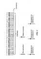
- the basic structure of a multi-carrier signal in the frequency domainis made up of subcarriers. Within a particular spectral band or channel, there are a fixed number of subcarriers. There are three types of subcarriers:
- Figure 1illustrates a basic structure of a multi-carrier signal in the frequency domain, made up of subcarriers.
- the data subcarrierscan be arranged into groups called subchannels to support scalability and multiple-access.
- the carriers forming one subchannelare not necessarily adjacent to each other. As depicted in Figure 1 , each user may use part or all of the subchannels.
- Figure 2illustrates a radio resource being divided into small units in both frequency (subchannels) and time domains (time slots).
- the basic structure of an MC signal in the time domainis made up of time slots to support multiple-access.
- FIG. 3illustrates a frame structure of a suitable OFDM system.
- a 20ms frame 310is divided into four 5ms subframes 312.
- One subframe 312consists of six time slots 314 and two special periods 316, which serve transition time from downlink to uplink and vise versa.
- the six time slots in one subframecan be configured as either uplink or downlink slots symmetrically or asymmetrically.
- Figure 4illustrates three examples of a subframe structure in an OFDM system: one symmetric configuration 412 and two asymmetric configurations 414, each with differing number of uplink (UL) and downlink (DL) slots.
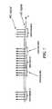
- Figure 5illustrates a slot structure of an OFDM system and an overlay system.
- One 800 ⁇ s time slot 510is comprised of 8 OFDM symbols 512, which are overlaid by DSSS signals 514 in the time domain.
- Two guard periods GP1 and GP2are allocated for the DSSS signal 514.
- Table 1Uplink system parameters Data Rate 2, 4, 8,16, 24 Mbps Modulation QPSK,16-QAM Coding rate 1/8, 1/4, 1/2, 3/4 IFFT/FFT size 1024 OFDM symbol duration 100 us Guard interval 11.11 us Subcarrier spacing 9.765625 kHz System sampling rate (fs) 11.52 MHz Channel spacing 10 MHz
- Figure 5illustrates the overlay of the MC and DSSS signals, where the DSSS signal overlaps with the MC signal in the time domain.
- the overlaid signalcan be aligned at the boundary of MC slot or MC symbol when they are synchronized (for example, DSSS signal #k in Figure 5 ). It can also be not aligned when they are not synchronized (for example, DSSS signal #j in Figure 5 ).
- the DSSS signalis placed at the period of cyclic prefix of the OFDM symbol.
- Figure 6is an illustration of MC signals overlaid with DSSS signals in the frequency domain where the power level of the DSSS signal is much lower than that of the MC signal.
- the subcarriers in a subchannelare not necessarily adjacent to each other in the frequency domain.
- Figure 7is similar to Figure 6 wherein not all MC subchannels are occupied. It illustrates a scenario where some MC subchannels are not energized.
- the MC signalis modulated on subcarriers in the frequency domain while the DSSS signal is modulated in either the time domain or the frequency domain.
- the modulation symbol on the DSSS sequenceis one and the sequence is unmodulated.
- FIG. 8illustrates a transmitter structure 800 of an MC and DSSS overlay system, wherein the MC signal and DSSS signal are added together prior to Digital to Analog (D/A) conversion 830.
- the top branch 810is an OFDM transmitter and the bottom branch 820 is the spread spectrum transmitter.
- the S/P bufferconverts the sequential inputs into parallel outputs, which are in turn inputted to the inverse discrete Fourier transform (IDFT).
- IDFTinverse discrete Fourier transform
- the outputs from the IDFTare the time domain signals, which are converted from parallel to sequential signals after a cyclic prefix is added. Adding the prefix can also be performed after the P/S conversion.
- the DSSS sequenceis modulated by the information bits or symbols and the modulated signals will undergo pulse-shaping filtering so that the signal spectrum meets specified criteria.
- a digital attenuator (G1)is used for the DSSS signal to adjust its transmitted signal level relative to the MC signal.
- the two signalsare overlaid in the digital domain before converting to a composite analog signal.
- a second analog variable gain (G2)is used subsequent to the D/A converter 830 to further control the power level of the transmitted signal.
- G1 and G2will be applied to the DSSS signal to provide sufficient transmission dynamic range.
- G2can be realized in multiple circuit stages.
- Figure 9illustrates a receiver structure 900 of an MC and DSSS overlay system.
- a composite signalis processed by a MC receiver 910 and DSSS receiver 920.
- A/DAnalog-to-Digital
- the MC receiverbasically performs a reverse process of the MC transmitter.
- the MC synchronization circuitcarries out the synchronization in both time and frequency for the receiver to function properly.
- the outputs of the P/Sare information bits or symbols.
- the signalis despread with a matched filter or a correlator, using the access sequence, to check if the correlation peak exceeds a predefined threshold.
- the information from the DSSS receiver 920will then be used to decode the mobile station's signature in the case of initial random access; to derive the channel information in the case of channel probing; or to decode the information bit in the case of short messaging.
- a rake receiveris used in the DSSS receiver 920 to improve its performance in a multi-path environment.
- the MC signalis processed as if no DSSS signal is present.
- advanced interference cancellation techniquescan be applied to the composite signal to cancel the DSSS signal from the composite signal thus maintaining almost the same MC performance.
- SINR MCP MC / N + I when the DSSS signal is not present
- SINR ⁇ MCP MC / N + I + P SS when the DSSS signal is present.
- the systemis designed such that the SINR' MC meets the SINR requirement for the MC signal and its performance is not compromised in spite of interference from the overlaid DSSS signal.
- the DSSS signalis power controlled such that P SS is well below the noise level, N .
- SINR SSP SS / N + I + P MC
- SINR ⁇ SSP SS * K SF / N + I + P MC
- SINR' SSmust be high enough to meet the performance requirement when detecting or decoding the information conveyed in the DSSS signal.
- K SFis chosen to be 1000, so that the DSSS signal is boosted with 30dB spreading gain after despreading.
- FIG 11illustrates a mobile station 1110 sending DSSS signals to its current serving base station or other base stations. The latter case is especially helpful in hand-off processes.
- a mobile station MS kis communicating with a BS i using an MC signal while transmitting a DSSS signal to BS k .
- C 1 (in dB)is set to a proper value so that the SINR of the MC as specified in equation (4) meets its requirement.
- C 2 (in dB)is an adjustment to compensate for the power control inaccuracy.
- Open loop power control inaccuracyis mainly caused by a discrepancy between an estimated path loss by the mobile station and the actual path loss.
- C 1is set to 9dB for MC using QPSK modulation with 1 ⁇ 2 error control coding or 15dB for MC using 16QAM modulation with 1 ⁇ 2 error control coding.
- C 2is set to 10dB or 2dB depending on whether the mobile station is under open loop power control or closed loop power control. Power control for the DSSS signal also eases the spectrum mask requirement for the DSSS signal because the DSSS signal level is much lower than that of the MC signal.
- the spreading factor of the DSSS signalneeds to be set high enough (e.g., 512 (27dB) or higher) so that the DSSS signal can be detected in normal conditions. This requires a sufficient number of bits of the A/D converter at the base station, for example, 12 bits.
- the D/A converter at the mobile stationuses 12 bits, among which 8 bits are targeted for the MC signal (assuming 3 bits are reserved for MC peak to average consideration). Thus, there are enough bits left for the DSSS signal even with significant attenuation relative to the MC signal.
- the base stationemploys interference cancellation techniques to cancel the DSSS interference to the MC signal.
- Figure 12illustrates a system for using an interference cancellation technique to cancel an interfering DSSS signal in a composite signal to obtain a clearer MC signal.
- a DSSS signalis detected by the DSSS receiver 1220; then it is subtracted (decision directed) from the total received signal to obtain a cleaner MC data signal in the MC receiver 1210, as illustrated in Figure 12 .
- multiple step iterative cancellationcan be applied to further improve the effectiveness of the interference cancellation.
- the MC receiverbasically performs a reverse process of the MC transmitter mentioned above.
- the MC synchronization circuitcarries out the synchronization in both time and frequency for the receiver to function properly.
- the outputs of the P/Sare information bits or symbols.
- DSSS sequencesare chosen to have good autocorrelation and cross-correlation properties (i.e., with high peak to sidelobe ratio).
- pulse-shapingis applied to restrict the spectrum mask of DSSS signals and to reduce impacts on the MC signals in the frequency domain.
- the transmitter pulse-shaping filter applied to the DSSS signalcan be a root-raised cosine (RRC) with roll-off factor ⁇ in the frequency domain.
- RRCroot-raised cosine
- Figure 13illustrates a DSSS signal and a MC signal fully overlaid or partially overlaid with an MC symbol or slot boundary in the time domain.
- the DSSS and the MC signalsmay be aligned at the symbol (or slot) boundary when they are synchronized, or partially overlapped in the time domain when they are not synchronized, as shown in Figure 13 , where a DSSS signal #m 1302 fully overlaps with a MC symbol (or slot) 1304 in time domain, while a DSSS signal #n 1306 overlaps with the MC symbol (or slot) only partially.
- Figure 14illustrates a DSSS signal with a high Peak to Average Ratio in the frequency domain causing strong interference to certain MC subcarriers.
- the sequence used to spread the DSSS signalhas to be designed to avoid cases where the DSSS signal may have a high Peak to Average ratio (PAR) in the frequency domain and its spikes may cause severe interference with some MC subcarriers, as illustrated in Figure 14 .
- the DSSS sequenceis designed so that, in partial or in full, it has low PAR in the frequency domain using signal processing techniques, such as a PAR reduction algorithm. Either binary or non binary sequences can be used.
- Golay complementary sequences, Reed-Muller codes, or the codes designed with similar construction methodsmay be used to control the PAR of DSSS sequences in the frequency domain, thereby limiting the interference of DSSS signals to MC signals, which are demodulated in the frequency domain.
- guard periodsare added to the DSSS signal which overlaps with one MC symbol, as shown by DSSS signal #p 1308 in Figure 13 . The guard periods ensure that a well-designed DSSS sequence (with low PAR in frequency domain) causes little interference with the MC subcarriers even when there is time misalignment in a DSSS signal relative to the OFDM symbol period.
- control subcarriersare more important than the data subcarriers and may need to have a better protection in the overlay system.
- Figure 15illustrates using spectrum nulls in the DSSS signal 1502 to protect an MC control subchannel.
- the DSSS sequenceis designed to have spectrum nulls at MC control subchannels to avoid excess interference with the uplink MC control signals 1504, as illustrated in Figure 15 .
- One such schemeis to use sub-sampling such that the chip rate of the DSSS signal is 1/2 or 2/3 of the system sampling rate, which means the DSSS spectrum will only occupy the center portion with a width of 5.76MHz or 7.68MHz out of the 10MHz available spectrum 1506, as shown in Figure 16 . Its interference with the MC sub-carriers over the rest of the spectrum will be much lower where the MC subchannels, carrying control information or using higher modulation subcarriers (such as 16QAM), are placed.
- Figure 10illustrates a DSSS signal used as initial random access by the mobile station MS j 1004, in an overlay system.
- MS l and MS kare transmitting MC signals to the base station BS i 1002 .
- the DSSS signalis used for initial random access and the MC signal is used by multiple mobile stations to transmit high rate data and related control information, as illustrated in Figure 10 .
- the mobile station MS jis transmitting its initial access DSSS signal simultaneously with the MC signals from other mobile stations (in this case, MS l and MS K ) to the base station BS i .
- a mobile stationIn the initial random access of a multi-carrier multiple access system, a mobile station cannot transmit directly onto the control subchannel because its transmission time and power have not been aligned with other mobile stations.
- this mobile stationWhen this mobile station powers up or wakes up from a sleep mode, it first listens to a base station broadcasting channel and finds an available random access DSSS channel. It then sends an initial random access signal over the DSSS channel with a certain signature code or sequence that is designated to the corresponding base station and is broadcasted to all the mobile stations by each base station.
- the initial access DSSS signalarrives at the base station together with MC signals from other mobile stations, each carrying data and control information.
- the initial power level of the DSSS signalis based on the open power loop control settings.
- a sufficient guard periodis reserved in the DSSS signal to account for initial time alignment uncertainty, as shown in Figure 5 .
- the base stationIf the base station successfully detects the DSSS signal, it sends the acknowledgement (ACK) carrying information such as a signature or other unique mobile station identifier and power and time adjustments of the mobile on the downlink control channel in the next available timeslot.
- ACKacknowledgement
- the mobile station whose transmission signature matches that of the acknowledgementthen moves to the designated uplink MC control channel using the assigned time and power values and further completes the message transmission.
- the mobile stationIf no feedback is received at the mobile station after a pre-defined number of slots, it assumes that the access slot was not detected by the base station, and will ramp up the transmission power of the DSSS signal by one step and re-transmit it, until it reaches the maximum allowable transmit signal power or the maximum retry times.
- the power ramping step of the mobile stationis set to be 1dB or 2dB which is configured by the base station on the downlink broadcasting channel.
- the maximum allowable transmit signal power and the retry timesare also controlled by the base station depending on the uplink modulation/coding scheme and available access channels.
- the DSSS signalcan also be used for channel probing and short messaging.
- the DSSS signalis used to assist estimation of channel characteristics.
- the mobile stationis already synchronized in time and frequency with the base station, and its transmission of the MC signal is under closed-loop power control with the base station.
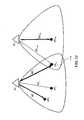
- Figure 17illustrates examples of communications between a base station 1702 and multiple mobile stations 1704 transmitting both DSSS and MC signals.
- DSSS signalis used for channel probing or to carry short messages.
- MS j 1704is transmitting both an MC signal and a DSSS signal to the base station BS i 1702. It is also under closed loop power control with the base station BS i 1702.
- the mobile station MS j 1704is transmitting its DSSS signal simultaneously with its own MC signal.
- Other mobile stationsin this case, MS l 1704 and MS K 1704 are transmitting either MC or DSSS signals to the base station BS i 1702.
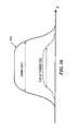
- Figure 18illustrates a typical channel response in the time domain 1802 and the frequency domain 1804.
- the channel profile in the frequency domain 1804can be obtained.
- a typical channel response in the time domain and frequency domain for a broadband wireless systemis shown in Figure 18 .
- the peaks of a channel response in timecan be detected.
- the initial power settingswill be much more accurate than by using open loop power control alone.
- the margin reserved for power control inaccuracycan be reduced to a much smaller value.
- a bigger spreading factorcan be used since no data information needs to be conveyed in the DSSS signal. This leaves a dynamic range large enough for detecting multi-path peaks from the output of the match filter or correlator, thereby generating a better channel profile.
- the base stationdictates the mobile station to transmit the channel probing DSSS when it needs an update of the mobile station's channel characteristics.
- the base stationpolls the mobile station during its silent period and gets an update of the mobile station's information such as transmission timing and power from the probing DSSS signal.
- the channel profile informationis used by the base station to determine the proper modulation/coding and pilot pattern.
- the channel profile informationis used for advanced antenna techniques such as beamforming.
- channel probing with the DSSS signalingis performed without close loop power control or time synchronization.
- the DSSS signalis used to carry short messages.
- the mobile stationis already synchronized in time and frequency with the base station, and its transmission of a MC signal is also under closed-loop power control with the base station.
- the mobile station MS jis transmitting its DSSS signal carrying a short message simultaneously with its own MC signal.
- Other mobile stationsin this case, MS l and MS K ) are transmitting either the MC signal or DSSS signal to the base station BS i .
- the short message carried by the DSSS signalhas a much lower data rate compared with that of the MC signal.
- short messaging using the DSSS signalingis performed without close loop power control or time synchronization.
Landscapes
- Engineering & Computer Science (AREA)
- Signal Processing (AREA)
- Computer Networks & Wireless Communication (AREA)
- Physics & Mathematics (AREA)
- Spectroscopy & Molecular Physics (AREA)
- Power Engineering (AREA)
- Mobile Radio Communication Systems (AREA)
Description
- A direct Sequence Spread Spectrum (DSSS) system is inherently capable of supporting multi-cell and multi-user access applications through the use of orthogonal spreading codes. The initial access of the physical channel and frequency planning are relatively easier because of interference averaging in a DSSS system. It has been widely used in some existing wireless networks. However, a DSSS system using orthogonal spreading codes, may suffer severely from the loss of orthogonally in a broadband environment due to multi-path propagation effects, which results in low spectral efficiency.
- In broadband wireless communications, Multi-Carrier (MC) technology is drawing more and more attention because of its capability. An MC system such as an Orthogonal Frequency Division Multiplexing (OFDM) system is capable of supporting broadband applications with higher spectral efficiency. An MC system mitigates the adverse effects of multi-path propagation in wireless environments by using cyclic prefixes to extend the signal period as the data is multiplexed on orthogonal sub-carriers. In effect, it converts a frequency selective channel into a number of parallel flat fading channels which can be easily equalized with simple one-tap equalizers. The modulator and the demodulator can be executed efficiently via the fast Fourier transform (FFT) with much lower cost. However, MC systems are vulnerable while operating in multi-user and multi-cell environments.
Figure 1 illustrates a basic structure of a multi-carrier signal in the frequency domain, made up of subcarriers.Figure 2 illustrates a radio resource being divided into small units in both frequency and time domains.Figure 3 illustrates a frame structure of an exemplary OFDM system.Figure 4 illustrates three examples of a subframe structure in the exemplary OFDM system.Figure 5 illustrates slot structure of the OFDM system and the overlay system.Figure 6 is an illustration of MC signals overlaid with DSSS signals in the frequency domain where the power level of the DSSS signal is much lower than that of the MC signal.Figure 7 is same asFigure 6 wherein not all MC subchannels are occupied.Figure 8 illustrates a transmitter structure of MC and DSSS overlay system.Figure 9 illustrates a receiver structure of MC and DSSS overlay system.Figure 10 illustrates examples of communications between a base station and multiple mobile stations transmitting DSSS and MC signals.Figure 11 illustrates a mobile station sending DSSS signals to its current serving base station, or other base stations.Figure 12 illustrates using interference cancellation technique to cancel interfering DSSS signal in a composite signal to obtain a clearer MC signal.Figure 13 illustrates a DSSS signal and a MC signal fully overlaid or partially overlaid at MC symbol or slot boundary in time domain.Figure 14 illustrates a DSSS signal with a high Peak to Average Ratio in frequency domain causing strong interference to certain MC subcarriers.Figure 15 illustrates using spectrum nulls in DSSS signal to protect an MC control subchannel.Figure 16 illustrates spectrum control for DSSS signal using simple sub-sampling method.Figure 17 illustrates examples of communications between a base station and multiple mobile stations transmitting both DSSS and MC signals.Figure 18 illustrates a typical channel response in the time and frequency domains. By estimating the peaks of a channel response in the time domain, the channel profile in the frequency domain can be obtained.- A broadband wireless communication system where both the Multi-Carrier (MC) and direct Sequence Spread Spectrum (DSSS) signals are intentionally overlaid together in both time and frequency domains is described. The system takes advantage of both MC and DSSS techniques to mitigate their weaknesses. The MC signal is used to carry broadband data signal for its high spectral efficiency, while the DSSS signal is used for special purpose processing, such as initial random access, channel probing, and short messaging, in which signal properties such as simplicity, self synchronization, and performance under severe interference are of concern. In the embodiments of this invention both the MC and the DSSS signals are distinguishable in normal operations and the interference between the overlaid signals is insufficient to degrade the expected performance of either signal.
- Unlike a typical CDMA system where the signals are designed to be orthogonal in the code domain or an OFDM system where the signals are designed to be orthogonal in frequency domain, the embodiments of this invention overlay the MC signal, which is transmitted without or with very low spreading, and the DSSS signal, which is transmitted at a power level lower than that of the MC signal.
- In accordance with aspects of certain embodiments of this invention, the MC signal is modulated on subcarriers in the frequency domain while the DSSS signal is modulated by the information bits or symbols in the time domain. In some cases the information bits modulating the DSSS sequence are always one.
- This invention further provides apparatus and means to implement the mentioned processes and methods in a broadband wireless multi-access and/or multi-cell network, using advanced techniques such as transmit power control, spreading signal design, and iterative cancellation.
- The mentioned MC system can be of any special format such as OFDM or Multi-Carrier Code Division Multiple Access (MC-CDMA). The presented methods and apparatus can be applied to downlink, uplink, or both, where the duplexing technique can be either Time Division Duplexing (TDD) or Frequency Division Duplexing (FDD).
- Various embodiments of the invention are described to provide specific details for thorough understanding and enablement; however, the aspects of the invention may be practiced without such details. In some instances, well-known structures and functions have not been shown or described in detail to avoid unnecessarily obscuring the essential matters.
- Unless the context clearly requires otherwise, throughout the description and the claims, the words "comprise," "comprising," and the like are to be construed in an inclusive sense as opposed to an exclusive or exhaustive sense; that is to say, in the sense of "including, but not limited to." Words using the singular or plural number also include the plural or singular number respectively. Additionally, the words "herein," "above," "below" and words of similar import, when used in this application, shall refer to this application as a whole and not to any particular portions of this application. When the claims use the word "or" in reference to a list of two or more items, that word covers all of the following interpretations of the word: any of the items in the list, all of the items in the list and any combination of the items in the list.TUFVESSON F ET AL: "OFDM time and frequency synchronization by spread spectrum pilot technique", COMMUNICATION THEORY MINI-CONFERENCE, 1999 VANCOUVER, BC, CANADA 6-10 JUNE 1999, PISCATAWAY, NJ, USA, IEEE, US, 6 June 1999, pages 115-119, XP010351105 discloses an OFDM system where a pseudo-noise (PN) sequence superimposed on an OFDM information signal is used for estimation of synchronization parameters of the OFDM system. In acquisition mode, the PN sequence is sent without transmission of the OFDM information signal. In tracking mode, the amplitude of the PN sequence is chosen such that the distortion of the transmitted OFDM information symbols is small.
It is the object of the present invention to provide an improved system and method operating over a frequency band within a multi-user multi-cell environment.
The object is solved by the subject matter of the independent claims.
Preferred embodiments of the present invention are defined by the dependent claims. - The physical media resource (e.g., radio or cable) in a multi-carrier communication system can be divided in both the frequency and time domains. This canonical division provides a high flexibility and fine granularity for resource sharing.
- The basic structure of a multi-carrier signal in the frequency domain is made up of subcarriers. Within a particular spectral band or channel, there are a fixed number of subcarriers. There are three types of subcarriers:
- 1. Data subcarriers, which contain information data;
- 2. Pilot subcarriers, whose phases and amplitudes are predetermined and made known to all receivers and which are employed for assisting system functions such as estimation of system parameters; and
- 3. Silent subcarriers, which have no energy and are used for guard bands and DC carrier.
Figure 1 illustrates a basic structure of a multi-carrier signal in the frequency domain, made up of subcarriers. The data subcarriers can be arranged into groups called subchannels to support scalability and multiple-access. The carriers forming one subchannel are not necessarily adjacent to each other. As depicted inFigure 1 , each user may use part or all of the subchannels.Figure 2 illustrates a radio resource being divided into small units in both frequency (subchannels) and time domains (time slots). The basic structure of an MC signal in the time domain is made up of time slots to support multiple-access.- An OFDM system is used in the system as a special case of an MC system. The system parameters for the uplink under consideration are listed in Table 1.
Figure 3 illustrates a frame structure of a suitable OFDM system. In this system, a20ms frame 310 is divided into four5ms subframes 312. Onesubframe 312 consists of sixtime slots 314 and twospecial periods 316, which serve transition time from downlink to uplink and vise versa. The six time slots in one subframe can be configured as either uplink or downlink slots symmetrically or asymmetrically. Figure 4 illustrates three examples of a subframe structure in an OFDM system: onesymmetric configuration 412 and twoasymmetric configurations 414, each with differing number of uplink (UL) and downlink (DL) slots.Figure 5 illustrates a slot structure of an OFDM system and an overlay system. One800µs time slot 510 is comprised of 8OFDM symbols 512, which are overlaid byDSSS signals 514 in the time domain. Two guard periods GP1 and GP2 are allocated for theDSSS signal 514.Table 1: Uplink system parameters Data Rate 2, 4, 8,16, 24 Mbps Modulation QPSK,16- QAM Coding rate 1/8, 1/4, 1/2, 3/4 IFFT/FFT size 1024 OFDM symbol duration 100 us Guard interval 11.11 us Subcarrier spacing 9.765625 kHz System sampling rate (fs) 11.52 MHz Channel spacing 10 MHz Figure 5 illustrates the overlay of the MC and DSSS signals, where the DSSS signal overlaps with the MC signal in the time domain. The overlaid signal can be aligned at the boundary of MC slot or MC symbol when they are synchronized (for example, DSSS signal #k inFigure 5 ). It can also be not aligned when they are not synchronized (for example, DSSS signal #j inFigure 5 ). In one embodiment, the DSSS signal is placed at the period of cyclic prefix of the OFDM symbol.Figure 6 is an illustration of MC signals overlaid with DSSS signals in the frequency domain where the power level of the DSSS signal is much lower than that of the MC signal. The subcarriers in a subchannel are not necessarily adjacent to each other in the frequency domain.Figure 7 is similar toFigure 6 wherein not all MC subchannels are occupied. It illustrates a scenario where some MC subchannels are not energized.- In another embodiment, the MC signal is modulated on subcarriers in the frequency domain while the DSSS signal is modulated in either the time domain or the frequency domain. In one embodiment the modulation symbol on the DSSS sequence is one and the sequence is unmodulated.
Figure 8 illustrates atransmitter structure 800 of an MC and DSSS overlay system, wherein the MC signal and DSSS signal are added together prior to Digital to Analog (D/A)conversion 830. InFigure 8 , thetop branch 810 is an OFDM transmitter and thebottom branch 820 is the spread spectrum transmitter. In the MC transmitter, the S/P buffer converts the sequential inputs into parallel outputs, which are in turn inputted to the inverse discrete Fourier transform (IDFT). The outputs from the IDFT are the time domain signals, which are converted from parallel to sequential signals after a cyclic prefix is added. Adding the prefix can also be performed after the P/S conversion. In the spread spectrum transmitter, the DSSS sequence is modulated by the information bits or symbols and the modulated signals will undergo pulse-shaping filtering so that the signal spectrum meets specified criteria.- A digital attenuator (G1) is used for the DSSS signal to adjust its transmitted signal level relative to the MC signal. The two signals are overlaid in the digital domain before converting to a composite analog signal. A second analog variable gain (G2) is used subsequent to the D/
A converter 830 to further control the power level of the transmitted signal. When the MC signal is not present, both G1 and G2 will be applied to the DSSS signal to provide sufficient transmission dynamic range. G2 can be realized in multiple circuit stages. Figure 9 illustrates areceiver structure 900 of an MC and DSSS overlay system. A composite signal is processed by aMC receiver 910 andDSSS receiver 920. At the receiver side, after automatic gain control (AGC), an Analog-to-Digital (A/D)converter 930 converts the received analog signal to digital signal. The MC receiver basically performs a reverse process of the MC transmitter. The MC synchronization circuit carries out the synchronization in both time and frequency for the receiver to function properly. The outputs of the P/S are information bits or symbols. To detect whether a DSSS signal is present, the signal is despread with a matched filter or a correlator, using the access sequence, to check if the correlation peak exceeds a predefined threshold. The information from theDSSS receiver 920 will then be used to decode the mobile station's signature in the case of initial random access; to derive the channel information in the case of channel probing; or to decode the information bit in the case of short messaging.- In one embodiment a rake receiver is used in the
DSSS receiver 920 to improve its performance in a multi-path environment. In another embodiment, the MC signal is processed as if no DSSS signal is present. In yet another embodiment, advanced interference cancellation techniques can be applied to the composite signal to cancel the DSSS signal from the composite signal thus maintaining almost the same MC performance. - The transmitted composite signal for user i can be represented by:


- Denoting the received power of the MC signal asPMC and the received power of the DSSS signal asPSS, the signal to interference and noise ratio (SINR) for the MC signal is:


- In one embodiment, the DSSS signal is power controlled such thatPSS is well below the noise level,N.
- On the other hand, the SINR for the DSSS signal is

- Denoting the spreading factor for the DSSS signal asKSF, the effective SINR for one symbol after despreading is:

- SINR'SS must be high enough to meet the performance requirement when detecting or decoding the information conveyed in the DSSS signal. In one embodiment,KSF is chosen to be 1000, so that the DSSS signal is boosted with 30dB spreading gain after despreading.
Figure 11 illustrates amobile station 1110 sending DSSS signals to its current serving base station or other base stations. The latter case is especially helpful in hand-off processes. In this Figure, a mobile station MSk is communicating with a BSi using an MC signal while transmitting a DSSS signal to BSk.- As discussed above, one design issue is to minimize the power of the DSSS signal to reduce its interference with the MC data signal. In one embodiment, the initial power setting of a mobile station,TMS_tx (in dBm), is set based on path loss,Lpath (in dB), and the desired received power level at the base station,PBS_rx_des (in dBm),

- C1 (in dB) is set to a proper value so that the SINR of the MC as specified in equation (4) meets its requirement. C2 (in dB) is an adjustment to compensate for the power control inaccuracy. Open loop power control inaccuracy is mainly caused by a discrepancy between an estimated path loss by the mobile station and the actual path loss.
- In one embodiment,C1 is set to 9dB for MC using QPSK modulation with ½ error control coding or 15dB for MC using 16QAM modulation with ½ error control coding. C2 is set to 10dB or 2dB depending on whether the mobile station is under open loop power control or closed loop power control. Power control for the DSSS signal also eases the spectrum mask requirement for the DSSS signal because the DSSS signal level is much lower than that of the MC signal.
- With total power offset ofC1 +C2 subtracted from an initial transmission power of the DSSS signal, the spreading factor of the DSSS signal needs to be set high enough (e.g., 512 (27dB) or higher) so that the DSSS signal can be detected in normal conditions. This requires a sufficient number of bits of the A/D converter at the base station, for example, 12 bits.
- In one embodiment, the D/A converter at the mobile station uses 12 bits, among which 8 bits are targeted for the MC signal (assuming 3 bits are reserved for MC peak to average consideration). Thus, there are enough bits left for the DSSS signal even with significant attenuation relative to the MC signal.
- In one embodiment, the base station employs interference cancellation techniques to cancel the DSSS interference to the MC signal.
Figure 12 illustrates a system for using an interference cancellation technique to cancel an interfering DSSS signal in a composite signal to obtain a clearer MC signal. First, a DSSS signal is detected by theDSSS receiver 1220; then it is subtracted (decision directed) from the total received signal to obtain a cleaner MC data signal in theMC receiver 1210, as illustrated inFigure 12 . In another embodiment, multiple step iterative cancellation can be applied to further improve the effectiveness of the interference cancellation. The MC receiver basically performs a reverse process of the MC transmitter mentioned above. The MC synchronization circuit carries out the synchronization in both time and frequency for the receiver to function properly. The outputs of the P/S are information bits or symbols. - DSSS sequences are chosen to have good autocorrelation and cross-correlation properties (i.e., with high peak to sidelobe ratio). In one embodiment, pulse-shaping is applied to restrict the spectrum mask of DSSS signals and to reduce impacts on the MC signals in the frequency domain. For example, the transmitter pulse-shaping filter applied to the DSSS signal can be a root-raised cosine (RRC) with roll-off factor α in the frequency domain. The impulse response of the chip impulse filterRC0(t) is

Figure 13 illustrates a DSSS signal and a MC signal fully overlaid or partially overlaid with an MC symbol or slot boundary in the time domain. The DSSS and the MC signals may be aligned at the symbol (or slot) boundary when they are synchronized, or partially overlapped in the time domain when they are not synchronized, as shown inFigure 13 , where a DSSS signal #m 1302 fully overlaps with a MC symbol (or slot) 1304 in time domain, while a DSSSsignal #n 1306 overlaps with the MC symbol (or slot) only partially.Figure 14 illustrates a DSSS signal with a high Peak to Average Ratio in the frequency domain causing strong interference to certain MC subcarriers. The sequence used to spread the DSSS signal has to be designed to avoid cases where the DSSS signal may have a high Peak to Average ratio (PAR) in the frequency domain and its spikes may cause severe interference with some MC subcarriers, as illustrated inFigure 14 . In one embodiment, the DSSS sequence is designed so that, in partial or in full, it has low PAR in the frequency domain using signal processing techniques, such as a PAR reduction algorithm. Either binary or non binary sequences can be used.- In another embodiment, Golay complementary sequences, Reed-Muller codes, or the codes designed with similar construction methods may be used to control the PAR of DSSS sequences in the frequency domain, thereby limiting the interference of DSSS signals to MC signals, which are demodulated in the frequency domain. In one embodiment, guard periods are added to the DSSS signal which overlaps with one MC symbol, as shown by DSSS
signal #p 1308 inFigure 13 . The guard periods ensure that a well-designed DSSS sequence (with low PAR in frequency domain) causes little interference with the MC subcarriers even when there is time misalignment in a DSSS signal relative to the OFDM symbol period. - Within MC subcarriers, the control subcarriers are more important than the data subcarriers and may need to have a better protection in the overlay system.
Figure 15 illustrates using spectrum nulls in theDSSS signal 1502 to protect an MC control subchannel. In one embodiment, the DSSS sequence is designed to have spectrum nulls at MC control subchannels to avoid excess interference with the uplinkMC control signals 1504, as illustrated inFigure 15 . One such scheme is to use sub-sampling such that the chip rate of the DSSS signal is 1/2 or 2/3 of the system sampling rate, which means the DSSS spectrum will only occupy the center portion with a width of 5.76MHz or 7.68MHz out of the 10MHzavailable spectrum 1506, as shown inFigure 16 . Its interference with the MC sub-carriers over the rest of the spectrum will be much lower where the MC subchannels, carrying control information or using higher modulation subcarriers (such as 16QAM), are placed.Figure 10 illustrates a DSSS signal used as initial random access by themobile station MS j 1004, in an overlay system. In the mean time, MSl and MSk are transmitting MC signals to thebase station BS i 1002 . In one embodiment of the invention, the DSSS signal is used for initial random access and the MC signal is used by multiple mobile stations to transmit high rate data and related control information, as illustrated inFigure 10 . In this arrangement the mobile station MSj is transmitting its initial access DSSS signal simultaneously with the MC signals from other mobile stations (in this case, MSl and MSK) to the base station BSi.- In the initial random access of a multi-carrier multiple access system, a mobile station cannot transmit directly onto the control subchannel because its transmission time and power have not been aligned with other mobile stations. When this mobile station powers up or wakes up from a sleep mode, it first listens to a base station broadcasting channel and finds an available random access DSSS channel. It then sends an initial random access signal over the DSSS channel with a certain signature code or sequence that is designated to the corresponding base station and is broadcasted to all the mobile stations by each base station.
- The initial access DSSS signal arrives at the base station together with MC signals from other mobile stations, each carrying data and control information. The initial power level of the DSSS signal is based on the open power loop control settings. A sufficient guard period is reserved in the DSSS signal to account for initial time alignment uncertainty, as shown in
Figure 5 . - If the base station successfully detects the DSSS signal, it sends the acknowledgement (ACK) carrying information such as a signature or other unique mobile station identifier and power and time adjustments of the mobile on the downlink control channel in the next available timeslot. The mobile station whose transmission signature matches that of the acknowledgement then moves to the designated uplink MC control channel using the assigned time and power values and further completes the message transmission.
- If no feedback is received at the mobile station after a pre-defined number of slots, it assumes that the access slot was not detected by the base station, and will ramp up the transmission power of the DSSS signal by one step and re-transmit it, until it reaches the maximum allowable transmit signal power or the maximum retry times. In one embodiment, the power ramping step of the mobile station is set to be 1dB or 2dB which is configured by the base station on the downlink broadcasting channel. The maximum allowable transmit signal power and the retry times are also controlled by the base station depending on the uplink modulation/coding scheme and available access channels. During the initial random access, the DSSS signal can also be used for channel probing and short messaging.
- In one embodiment of the invention, the DSSS signal is used to assist estimation of channel characteristics. In this case, the mobile station is already synchronized in time and frequency with the base station, and its transmission of the MC signal is under closed-loop power control with the base station.
Figure 17 illustrates examples of communications between abase station 1702 and multiplemobile stations 1704 transmitting both DSSS and MC signals. DSSS signal is used for channel probing or to carry short messages. In this case,MS j 1704 is transmitting both an MC signal and a DSSS signal to thebase station BS i 1702. It is also under closed loop power control with thebase station BS i 1702. InFigure 17 , themobile station MS j 1704 is transmitting its DSSS signal simultaneously with its own MC signal. Other mobile stations (in this case,MS l 1704 and MSK 1704) are transmitting either MC or DSSS signals to thebase station BS i 1702.Figure 18 illustrates a typical channel response in thetime domain 1802 and thefrequency domain 1804. By estimating the peaks of a channel response in thetime domain 1802, the channel profile in thefrequency domain 1804 can be obtained. A typical channel response in the time domain and frequency domain for a broadband wireless system is shown inFigure 18 . Using a matched filter in the DSSS receiver at the base station, the peaks of a channel response in time can be detected.- When closed loop power control is used, the initial power settings will be much more accurate than by using open loop power control alone. Thus, the margin reserved for power control inaccuracy can be reduced to a much smaller value. Furthermore, a bigger spreading factor can be used since no data information needs to be conveyed in the DSSS signal. This leaves a dynamic range large enough for detecting multi-path peaks from the output of the match filter or correlator, thereby generating a better channel profile. When and how often a mobile station should send the DSSS signal for channel probing is configurable by the network or the mobile station.
- In one embodiment, the base station dictates the mobile station to transmit the channel probing DSSS when it needs an update of the mobile station's channel characteristics. In another embodiment, the base station polls the mobile station during its silent period and gets an update of the mobile station's information such as transmission timing and power from the probing DSSS signal. In yet another embodiment, the channel profile information is used by the base station to determine the proper modulation/coding and pilot pattern. In yet another embodiment, the channel profile information is used for advanced antenna techniques such as beamforming. In one embodiment, channel probing with the DSSS signaling is performed without close loop power control or time synchronization.
- In one embodiment of the invention, the DSSS signal is used to carry short messages. In this case, the mobile station is already synchronized in time and frequency with the base station, and its transmission of a MC signal is also under closed-loop power control with the base station. As shown in
Figure 17 , the mobile station MSj is transmitting its DSSS signal carrying a short message simultaneously with its own MC signal. Other mobile stations (in this case, MSl and MSK) are transmitting either the MC signal or DSSS signal to the base station BSi. In this case, the short message carried by the DSSS signal has a much lower data rate compared with that of the MC signal. In another embodiment, short messaging using the DSSS signaling is performed without close loop power control or time synchronization.


Claims (16)
- A communication system operating over a frequency band within a multi-user multi-cell environment, the system comprising:transmitter means configured to transmit an Orthogonal Frequency Division Multiplexing (OFDM) signal within the frequency band; andtransmitter means configured to transmit a Direct Sequence Spread Spectrum, DSSS, signal within the frequency band;wherein:the OFDM signal carries broadband data and control information;the DSSS signal performs initial random access, channel probing, or short messaging, ora combination thereof;the OFDM signal is transmitted according to a time frame structure, each frame containing a plurality of time slots and each time slot containing a plurality of OFDM symbols; the systemcharacterized in that the DSSS signal occupies a fraction of the frequency band and a guard period is added to the DSSS signal to accommodate time alignment uncertainty with regard to the time frame structure; andthe DSSS signal, together with its guard period, has a time duration longer than multiple OFDM symbol periods and fully or partially overlaps with a time slot in the time frame structure.
- The system of claim 1, wherein a subcarrier of the OFDM signal is energized at a desired power level or not energized at all.
- The system of claim 1, wherein the DSSS signal is power controlled with an initial power setting of the transmitter based on path loss,Lpath
- The system of claim 1, wherein the system controls the DSSS signals power to meet spectrum mask requirements.
- The system of claim 1, wherein the control information is carried over a subchannel within the frequency band.
- The system of claim 5, wherein the DSSS signal occupies a portion of the spectrum that does not overlap with the subchannel carrying the control information.
- The system of claim 1, wherein the DSSS signal contains a signature sequence that is designated to a base station within the multi-user multi-cell environment.
- The system of claim 1, wherein the DSSS signal is generated from a binary or non-binary code sequence in the frequency domain or the time domain.
- The system of claim 8, wherein the code sequence is a Golay complementary sequence, a Reed-Muller code, or a sequence constructed to reduce peak-to-average ratio.
- A broadband wireless communication method for a device operating over a frequency band within a multi-user multi-cell environment, the method comprising:transmitting an Orthogonal Frequency Division Multiplexing, OFDM, signal within the frequency band; andtransmitting a Direct Sequence Spread Spectrum, ODSSS, signal within the frequency band,wherein:the OFDM signal carries broadband data and control information;the DSSS signal performs initial random access, channel probing, or short messaging, ora combination thereof;the OFDM signal is transmitted according to a time frame structure, each frame containing a plurality of time slots and each time slot containing a plurality of OFDM symbols; the methodcharacterized in that the DSSS signal occupies a fraction of the frequency band and a guard period is added to the DSSS signal to accommodate time alignment uncertainty with regard to the time frame structure; andthe DSSS signal, together with its guard period, has a time duration longer than multiple OFDM symbol periods and fully or partially overlaps with a time slot in the time frame.
- The method of claim 10, wherein the DSSS signal is power controlled with an initial power setting of the transmitter based on path loss,Lpath
- The method of claim 10, wherein the control information is carried over a subchannel within the frequency band.
- The method of claim 12, wherein the DSSS signal occupies a portion of the spectrum that does not overlap with the subchannel carrying the control information.
- The method of claim 10, wherein the DSSS signal contains a signature sequence that is designated to a base station within the multi-user multi-cell environment.
- The method of claim 10, wherein the DSSS signal is generated from a binary or non-binary code sequence in the frequency domain or the time domain.
- The method of claim 15, wherein the code sequence is a Golay complementary sequence, a Reed-Muller code, or a sequence constructed to reduce peak-to-average ratio.
Priority Applications (4)
| Application Number | Priority Date | Filing Date | Title |
|---|---|---|---|
| EP18196596.3AEP3457652B1 (en) | 2004-01-29 | 2005-01-27 | Methods and apparatus for overlaying multi-carrier and direct sequence spread spectrum signals in a broadband wireless communication system |
| EP14000130.6AEP2723003B1 (en) | 2004-01-29 | 2005-01-27 | Methods and apparatus for overlaying multi-carrier and direct sequence spread spectrum signals in a broadband wireless communication system |
| EP17163371.2AEP3208985B1 (en) | 2004-01-29 | 2005-01-27 | Methods and apparatus for overlaying multi-carrier and direct sequence spread spectrum signals in a broadband wireless communication system |
| EP21170377.2AEP3876490B1 (en) | 2004-01-29 | 2005-01-27 | Methods and apparatus for overlaying multi-carrier and direct sequence spread spectrum signals in a broadband wireless communication system |
Applications Claiming Priority (3)
| Application Number | Priority Date | Filing Date | Title |
|---|---|---|---|
| US54003204P | 2004-01-29 | 2004-01-29 | |
| US54058604P | 2004-01-30 | 2004-01-30 | |
| PCT/US2005/003518WO2005074166A1 (en) | 2004-01-29 | 2005-01-27 | Methods and apparatus for overlaying multi-carrier and direct sequence spread spectrum signals in a broadband wireless communication system |
Related Child Applications (4)
| Application Number | Title | Priority Date | Filing Date |
|---|---|---|---|
| EP18196596.3ADivisionEP3457652B1 (en) | 2004-01-29 | 2005-01-27 | Methods and apparatus for overlaying multi-carrier and direct sequence spread spectrum signals in a broadband wireless communication system |
| EP21170377.2ADivisionEP3876490B1 (en) | 2004-01-29 | 2005-01-27 | Methods and apparatus for overlaying multi-carrier and direct sequence spread spectrum signals in a broadband wireless communication system |
| EP14000130.6ADivisionEP2723003B1 (en) | 2004-01-29 | 2005-01-27 | Methods and apparatus for overlaying multi-carrier and direct sequence spread spectrum signals in a broadband wireless communication system |
| EP17163371.2ADivisionEP3208985B1 (en) | 2004-01-29 | 2005-01-27 | Methods and apparatus for overlaying multi-carrier and direct sequence spread spectrum signals in a broadband wireless communication system |
Publications (3)
| Publication Number | Publication Date |
|---|---|
| EP1712019A1 EP1712019A1 (en) | 2006-10-18 |
| EP1712019A4 EP1712019A4 (en) | 2012-05-02 |
| EP1712019B1true EP1712019B1 (en) | 2014-01-15 |
Family
ID=34830499
Family Applications (1)
| Application Number | Title | Priority Date | Filing Date |
|---|---|---|---|
| EP05712825.8AExpired - LifetimeEP1712019B1 (en) | 2004-01-29 | 2005-01-27 | Methods and apparatus for overlaying multi-carrier and direct sequence spread spectrum signals in a broadband wireless communication system |
Country Status (6)
| Country | Link |
|---|---|
| US (11) | US7864725B2 (en) |
| EP (1) | EP1712019B1 (en) |
| KR (1) | KR100818774B1 (en) |
| CN (1) | CN102064848B (en) |
| ES (1) | ES2885101T3 (en) |
| WO (1) | WO2005074166A1 (en) |
Families Citing this family (54)
| Publication number | Priority date | Publication date | Assignee | Title |
|---|---|---|---|---|
| ES2885101T3 (en)* | 2004-01-29 | 2021-12-13 | Neo Wireless Llc | Procedures and apparatus for superimposing direct sequence and multi-carrier spread spectrum signals in a broadband wireless communication system |
| CN101854188B (en) | 2004-01-29 | 2013-03-13 | 桥扬科技有限公司 | Methods and apparatus for multi-carrier, multi-cell wireless communication networks |
| WO2005081439A1 (en) | 2004-02-13 | 2005-09-01 | Neocific, Inc. | Methods and apparatus for multi-carrier communication systems with adaptive transmission and feedback |
| KR100635011B1 (en)* | 2004-11-16 | 2006-10-16 | 한국전자통신연구원 | Transmitter of orthogonal frequency division multiple access system capable of adjusting gain according to the number of subchannels and data transmission method |
| US7715460B2 (en) | 2005-04-22 | 2010-05-11 | Interdigital Technology Corporation | Hybrid orthogonal frequency division multiple access system and method |
| US8279868B2 (en) | 2005-05-17 | 2012-10-02 | Pine Valley Investments, Inc. | System providing land mobile radio content using a cellular data network |
| US8145262B2 (en) | 2005-05-17 | 2012-03-27 | Pine Valley Investments, Inc. | Multimode land mobile radio |
| KR100810280B1 (en)* | 2005-05-27 | 2008-03-06 | 삼성전자주식회사 | Method and system for transmitting and receiving data in frequency overlay communication system |
| US7894818B2 (en)* | 2005-06-15 | 2011-02-22 | Samsung Electronics Co., Ltd. | Apparatus and method for multiplexing broadcast and unicast traffic in a multi-carrier wireless network |
| US20080260003A1 (en)* | 2005-09-14 | 2008-10-23 | Universite De Rennes 1 | Method for Transmitting a Multicarrier Spectrum-Spread Signal, Reception Method, Corresponding Transmitting, Receiving Device and Signal |
| US8693430B2 (en) | 2005-09-28 | 2014-04-08 | Neocific, Inc. | Method and system for multi-carrier packet communication with reduced overhead |
| CN101147343B (en)* | 2005-09-28 | 2012-06-20 | 桥扬科技有限公司 | Method for multi-carrier packet communication with reduced overhead |
| US8194682B2 (en)* | 2006-08-07 | 2012-06-05 | Pine Valley Investments, Inc. | Multiple protocol land mobile radio system |
| KR100810351B1 (en)* | 2006-11-15 | 2008-03-04 | 재단법인서울대학교산학협력재단 | Channel Probing System and Method in Communication System |
| KR101390110B1 (en)* | 2007-02-22 | 2014-04-28 | 삼성전자주식회사 | Apparatus and method for transmitting and receiving a signal in a communication system |
| US8942150B2 (en)* | 2007-03-19 | 2015-01-27 | Qualcomm Incorporated | Uplink timing control |
| WO2009069177A1 (en)* | 2007-11-28 | 2009-06-04 | Fujitsu Limited | Radio transmitting apparatus, radio receiving apparatus, radio transmitting/receiving system, and methods therefor |
| KR100904533B1 (en) | 2008-01-11 | 2009-06-25 | 엘지전자 주식회사 | Transmission timing adjustment method, continuous packet transmission method and mobile communication terminal |
| US8526421B2 (en)* | 2008-02-25 | 2013-09-03 | Nxp B.V. | Arrangement and approach for time slot index synchronization for wireless communications |
| US8406168B2 (en) | 2009-03-13 | 2013-03-26 | Harris Corporation | Asymmetric broadband data radio network |
| US8693305B2 (en)* | 2009-08-24 | 2014-04-08 | Qualcomm Incorporated | Method and apparatus for detecting OFDM signals in the presence of frequency orthogonal OFDM interferers |
| US9832769B2 (en) | 2009-09-25 | 2017-11-28 | Northwestern University | Virtual full duplex network communications |
| US20110116421A1 (en)* | 2009-09-25 | 2011-05-19 | Dongning Guo | Rapid on-off-division duplex network communications |
| US8718101B2 (en)* | 2009-12-29 | 2014-05-06 | Acer Incorporated | Pilot selection method, wireless communication system and base station thereof |
| US20120008555A1 (en)* | 2010-06-23 | 2012-01-12 | Qualcomm Incorporated | Transmit and receive processing in the presence of interference in a wireless network |
| US9059813B2 (en) | 2011-02-13 | 2015-06-16 | Lg Electronics Inc. | Method for transmitting uplink control information and user equipment, and method for receiving uplink control information and base station |
| GB2489922A (en)* | 2011-04-06 | 2012-10-17 | Univ Bangor | Synchronising optical OFDM signal with pattern of DC offset levels superimposed upon OFDM symbols |
| US9736737B2 (en)* | 2011-07-13 | 2017-08-15 | Htc Corporation | Method of handling random access procedure with deactivation timer |
| CN102307174B (en)* | 2011-09-09 | 2013-04-24 | 北京交通大学 | Low density trap wave point setting method |
| US8995560B2 (en)* | 2011-10-26 | 2015-03-31 | Google Technology Holdings LLC | Power detection of individual carriers of a multiple-carrier wideband signal |
| US8731027B2 (en)* | 2011-12-05 | 2014-05-20 | Battelle Energy Alliance, Llc | Methods and apparatuses using filter banks for multi-carrier spread-spectrum signals |
| US8565181B2 (en)* | 2012-02-06 | 2013-10-22 | Neocific, Inc. | Methods and apparatus for multi-carrier communications with efficient control signaling |
| US9112634B2 (en)* | 2012-02-10 | 2015-08-18 | Qualcomm Incorporated | Reducing network acquisition time |
| KR101997457B1 (en)* | 2012-02-10 | 2019-07-08 | 엘지전자 주식회사 | Method and apparatus for accessing channel in wlan system |
| US9832286B2 (en) | 2013-03-14 | 2017-11-28 | Angelo Marino TUZI | Asynchronous ubiquitous protocol |
| WO2014172849A1 (en)* | 2013-04-24 | 2014-10-30 | 华为技术有限公司 | Transmitter and signal transmission method |
| KR101473592B1 (en)* | 2013-12-05 | 2014-12-16 | 한국항공우주연구원 | Apparatus and method for distortion signal detection |
| US10693602B2 (en)* | 2015-05-29 | 2020-06-23 | Futurewei Technologies, Inc. | System and method for a long-term evolution (LTE)-compatible subframe structure for wideband LTE |
| US10656244B2 (en)* | 2016-04-08 | 2020-05-19 | General Radar Corp. | Reconfigurable correlator (pulse compression receiver) and beam former based on multi-gigabit serial transceivers (SERDES) |
| US10887143B2 (en)* | 2016-05-06 | 2021-01-05 | Samsung Electronics Co., Ltd. | Method and apparatus for initial access in wireless communication systems |
| WO2018028838A1 (en) | 2016-08-12 | 2018-02-15 | Telefonaktiebolaget Lm Ericsson (Publ) | Technique for determining a channel width of a channel used in a wireless communication network |
| DE102017219685B3 (en) | 2017-11-06 | 2019-05-09 | Laird Dabendorf Gmbh | Method and apparatus for amplifying radio signals between a terminal and an antenna in a first frequency band and in a second frequency band |
| WO2019231823A1 (en) | 2018-05-29 | 2019-12-05 | Skyworks Solutions, Inc. | Beamforming communication systems with power control based on antenna pattern configuration |
| US10581481B1 (en) | 2018-09-18 | 2020-03-03 | Battelle Energy Alliance, Llc | Communication device, spread-spectrum receiver, and related method using normalized matched filter for improving signal-to-noise ratio in harsh environments |
| US11477738B2 (en)* | 2018-09-28 | 2022-10-18 | Ntt Docomo, Inc. | Method and device for uplink power control |
| CN109361497A (en)* | 2018-10-11 | 2019-02-19 | 天津大学 | A pilot design method for OFDM cognitive radio system |
| CN111757448B (en)* | 2019-03-29 | 2021-09-07 | 华为技术有限公司 | A power control method and device |
| US12088398B1 (en)* | 2020-02-29 | 2024-09-10 | Space Exploration Technologies Corp. | Configurable orthogonal frequency division multiplexing (OFDM) signal and transmitter and receiver for same |
| US12126374B2 (en) | 2020-03-06 | 2024-10-22 | Battelle Energy Alliance, Llc | Spread spectrum communication, and associated devices, systems, and methods |
| US11122525B1 (en)* | 2020-06-24 | 2021-09-14 | Charter Communications Operating, Llc | Wireless channel access and power adjust access requests |
| KR20220076108A (en) | 2020-11-30 | 2022-06-08 | 삼성전자주식회사 | Low complexity widely linear reception processing in multi-antenna wireless communication system and method thereof |
| CN112688755B (en)* | 2020-12-22 | 2022-06-03 | 重庆邮电大学 | Method and device for generating length 3N four-phase aperiodic complementary sequence pair signal |
| KR20220102347A (en) | 2021-01-13 | 2022-07-20 | 삼성전자주식회사 | Electronic device for controlling spread spectrum clock generator and operating method thereof |
| US12308947B2 (en)* | 2022-09-13 | 2025-05-20 | Qualcomm Incorporated | Concurrent code division and frequency division signaling via an uplink channel |
Family Cites Families (228)
| Publication number | Priority date | Publication date | Assignee | Title |
|---|---|---|---|---|
| US3488445A (en) | 1966-11-14 | 1970-01-06 | Bell Telephone Labor Inc | Orthogonal frequency multiplex data transmission system |
| US7274652B1 (en) | 2000-06-02 | 2007-09-25 | Conexant, Inc. | Dual packet configuration for wireless communications |
| US5519730A (en) | 1990-06-12 | 1996-05-21 | Jasper; Steven C. | Communication signal having a time domain pilot component |
| EP0565507A3 (en) | 1992-04-10 | 1994-11-30 | Ericsson Ge Mobile Communicat | Power control for random access call set-up in a mobile telephone system |
| US5471647A (en) | 1993-04-14 | 1995-11-28 | The Leland Stanford Junior University | Method for minimizing cross-talk in adaptive transmission antennas |
| EP0647982B1 (en) | 1993-08-12 | 2002-10-23 | Nortel Networks Limited | Base station antenna arrangement |
| US6334219B1 (en) | 1994-09-26 | 2001-12-25 | Adc Telecommunications Inc. | Channel selection for a hybrid fiber coax network |
| FI99252C (en)* | 1995-07-03 | 1997-12-29 | Nokia Mobile Phones Ltd | Combined radio signal modulation and multi-use method |
| SE515752C2 (en) | 1995-08-28 | 2001-10-08 | Telia Ab | Direct access in OFDM system |
| US5825807A (en)* | 1995-11-06 | 1998-10-20 | Kumar; Derek D. | System and method for multiplexing a spread spectrum communication system |
| JP3142771B2 (en)* | 1996-02-22 | 2001-03-07 | シャープ株式会社 | Orthogonal frequency division multiplex signal transmission system |
| JP3289610B2 (en) | 1996-07-31 | 2002-06-10 | 日本ビクター株式会社 | OFDM demodulator and method |
| US5898338A (en) | 1996-09-20 | 1999-04-27 | Spectrian | Adaptive digital predistortion linearization and feed-forward correction of RF power amplifier |
| US6192068B1 (en) | 1996-10-03 | 2001-02-20 | Wi-Lan Inc. | Multicode spread spectrum communications system |
| GB2320646B (en)* | 1996-10-18 | 2001-04-11 | Motorola Ltd | Mobile telephone systems |
| DE19647833B4 (en)* | 1996-11-19 | 2005-07-07 | Deutsches Zentrum für Luft- und Raumfahrt e.V. | Method for simultaneous radio transmission of digital data between a plurality of subscriber stations and a base station |
| JPH10210002A (en)* | 1997-01-17 | 1998-08-07 | Victor Co Of Japan Ltd | Mobile communication system |
| US5933421A (en) | 1997-02-06 | 1999-08-03 | At&T Wireless Services Inc. | Method for frequency division duplex communications |
| WO1998037638A2 (en) | 1997-02-24 | 1998-08-27 | At & T Wireless Services, Inc. | Highly bandwidth-efficient communications |
| US6175550B1 (en)* | 1997-04-01 | 2001-01-16 | Lucent Technologies, Inc. | Orthogonal frequency division multiplexing system with dynamically scalable operating parameters and method thereof |
| JP3535344B2 (en) | 1997-05-30 | 2004-06-07 | 松下電器産業株式会社 | Multicarrier transmission method, data transmission device, mobile station device, and base station device |
| US5867478A (en) | 1997-06-20 | 1999-02-02 | Motorola, Inc. | Synchronous coherent orthogonal frequency division multiplexing system, method, software and device |
| US6680928B1 (en)* | 1997-07-22 | 2004-01-20 | Ericsson Inc. | Communications system and method for multi-carrier orthogonal coding |
| JPH1174861A (en) | 1997-08-27 | 1999-03-16 | Sony Corp | Radio communication system |
| US6101179A (en) | 1997-09-19 | 2000-08-08 | Qualcomm Incorporated | Accurate open loop power control in a code division multiple access communication system |
| US7430257B1 (en)* | 1998-02-12 | 2008-09-30 | Lot 41 Acquisition Foundation, Llc | Multicarrier sub-layer for direct sequence channel and multiple-access coding |
| US7787514B2 (en) | 1998-02-12 | 2010-08-31 | Lot 41 Acquisition Foundation, Llc | Carrier interferometry coding with applications to cellular and local area networks |
| EP0938193A1 (en) | 1998-02-18 | 1999-08-25 | Sony International (Europe) GmbH | Header structure for TDD systems |
| US5929704A (en) | 1998-02-20 | 1999-07-27 | Spectrian | Control of RF error extraction using auto-calibrating RF correlator |
| US6643281B1 (en) | 1998-03-05 | 2003-11-04 | At&T Wireless Services, Inc. | Synchronization preamble method for OFDM waveforms in a communications system |
| US6078216A (en) | 1998-03-31 | 2000-06-20 | Spectrian Corporation | Aliased wide band performance monitor for adjusting predistortion and vector modulator control parameters of RF amplifier |
| US6643275B1 (en) | 1998-05-15 | 2003-11-04 | Telefonaktiebolaget Lm Ericsson (Publ) | Random access in a mobile telecommunications system |
| EP1005243A1 (en) | 1998-11-24 | 2000-05-31 | TELEFONAKTIEBOLAGET LM ERICSSON (publ) | Access method for mobile telecommunication system |
| AU2159099A (en) | 1998-12-08 | 2000-06-26 | Nokia Networks Oy | A method for call setup in a radio telecommunication network using macro diversity |
| JP2000244441A (en) | 1998-12-22 | 2000-09-08 | Matsushita Electric Ind Co Ltd | OFDM transceiver |
| US6434364B1 (en)* | 1998-12-24 | 2002-08-13 | Telefonaktiebolaget Lm Ericsson (Publ) | Wireless communication system that supports mobile test software agents |
| US6501788B1 (en) | 1999-01-22 | 2002-12-31 | Ericsson Inc. | Apparatus and methods for intereference cancellation in spread spectrum communications systems |
| US6731673B1 (en) | 1999-02-19 | 2004-05-04 | Nortel Networks Limited | Synchronization channel with cyclic hierarchical sequences and method for cell site search with low detector complexity |
| US6141393A (en) | 1999-03-03 | 2000-10-31 | Motorola, Inc. | Method and device for channel estimation, equalization, and interference suppression |
| US6088347A (en) | 1999-03-10 | 2000-07-11 | Massachusetts Institute Of Technology | Variable chip rate code-division multiple access |
| US6711120B1 (en) | 1999-03-11 | 2004-03-23 | Flarion Technologies, Inc. | Orthogonal frequency division multiplexing based spread spectrum multiple access |
| US6480558B1 (en) | 1999-03-17 | 2002-11-12 | Ericsson Inc. | Synchronization and cell search methods and apparatus for wireless communications |
| US6574267B1 (en) | 1999-03-22 | 2003-06-03 | Golden Bridge Technology, Inc. | Rach ramp-up acknowledgement |
| US7133352B1 (en)* | 1999-09-20 | 2006-11-07 | Zion Hadad | Bi-directional communication channel |
| JP4342109B2 (en) | 1999-04-29 | 2009-10-14 | シーメンス アクチエンゲゼルシヤフト | Method for synchronizing base station and mobile station, base station and mobile station |
| DE60045171D1 (en) | 1999-04-29 | 2010-12-09 | Samsung Electronics Co Ltd | Device and method for channel synchronization in a W-CDMA communication system |
| CA2276971A1 (en) | 1999-07-06 | 2001-01-06 | Wen Tong | Preamble using golay sequence for access channel in cellular communications systems |
| FI111438B (en) | 1999-07-09 | 2003-07-15 | Nokia Corp | Method of producing a symbol sequence |
| DE19935480A1 (en)* | 1999-07-28 | 2001-02-22 | Infineon Technologies Ag | Method for estimating the channel impulse responses of a mobile radio channel |
| US6611507B1 (en) | 1999-07-30 | 2003-08-26 | Nokia Corporation | System and method for effecting information transmission and soft handoff between frequency division duplex and time division duplex communications systems |
| US7567624B1 (en) | 1999-07-30 | 2009-07-28 | Texas Instruments Incorporated | System and method of communicating using combined signal parameter diversity |
| US6483814B1 (en) | 1999-08-25 | 2002-11-19 | Hrl Laboratories, Llc | Channel-adaptive radio modem |
| JP2001086086A (en) | 1999-09-17 | 2001-03-30 | Matsushita Electric Ind Co Ltd | Wireless transmitting / receiving apparatus and wireless communication method |
| JP3522619B2 (en) | 2000-01-05 | 2004-04-26 | 株式会社エヌ・ティ・ティ・ドコモ | Transmitter in multi-carrier CDMA transmission system |
| KR100319927B1 (en) | 2000-01-11 | 2002-01-09 | 윤종용 | Apparatus for cell search and method for acquiring the code perculiar to each cell in asynchronous wideband CDMA receiver |
| US7512409B1 (en) | 2000-01-13 | 2009-03-31 | Zion Hadad Communications Ltd. | Cellular network system |
| JP3581072B2 (en) | 2000-01-24 | 2004-10-27 | 株式会社エヌ・ティ・ティ・ドコモ | Channel configuration method and base station using the method |
| US6922388B1 (en) | 2000-02-11 | 2005-07-26 | Lucent Technologies Inc. | Signal construction, detection and estimation for uplink timing synchronization and access control in a multi-access wireless communication system |
| GB2359456B (en) | 2000-02-19 | 2003-09-17 | Nec Technologies | Method for frequency offset estimation in a direct sequence spread spectrum communications receiver |
| SG108240A1 (en) | 2000-02-23 | 2005-01-28 | Ntt Docomo Inc | Multi-carrier cdma radio transmitting method and apparatus, and channel estimation method and apparatus for multi-carrier cdma radio transmitting system |
| DE10008653A1 (en) | 2000-02-24 | 2001-09-06 | Siemens Ag | Improvements in a radio communication system |
| EP1130840A3 (en) | 2000-02-29 | 2003-11-19 | Kabushiki Kaisha Toshiba | Spread-spectrum multicarrier modulation for cellular communication |
| US6600772B1 (en) | 2000-03-21 | 2003-07-29 | Interdigital Communications Corporation | Combined closed loop/open loop power control in a time division duplex communication system |
| US20020154705A1 (en) | 2000-03-22 | 2002-10-24 | Walton Jay R. | High efficiency high performance communications system employing multi-carrier modulation |
| JP2001285927A (en) | 2000-03-29 | 2001-10-12 | Matsushita Electric Ind Co Ltd | Communication terminal device and wireless communication method |
| US6961364B1 (en) | 2000-04-18 | 2005-11-01 | Flarion Technologies, Inc. | Base station identification in orthogonal frequency division multiplexing based spread spectrum multiple access systems |
| JP2001326586A (en) | 2000-05-17 | 2001-11-22 | Nec Corp | Cdma communication system and channel estimate method used for it |
| GB0012258D0 (en)* | 2000-05-19 | 2000-07-12 | Fujitsu Ltd | Transmission rate changes in communications networks |
| CN1172463C (en) | 2000-06-12 | 2004-10-20 | 三星电子株式会社 | Method for allocating uplink random access channel in code division multiple access mobile communication system |
| EP1720277B1 (en) | 2000-07-05 | 2017-09-27 | Sony Deutschland Gmbh | Pilot pattern design for multiple antennas in an OFDM system |
| US7418043B2 (en) | 2000-07-19 | 2008-08-26 | Lot 41 Acquisition Foundation, Llc | Software adaptable high performance multicarrier transmission protocol |
| EP1178640B1 (en) | 2000-08-01 | 2006-05-24 | Sony Deutschland GmbH | Device and method for channel estimating an OFDM system |
| US6850481B2 (en) | 2000-09-01 | 2005-02-01 | Nortel Networks Limited | Channels estimation for multiple input—multiple output, orthogonal frequency division multiplexing (OFDM) system |
| FR2814011B1 (en) | 2000-09-14 | 2003-10-24 | France Telecom | OPTIMAL ESTIMATION METHOD OF A PROPAGATION CHANNEL BASED ONLY ON PILOT SYMBOLS AND CORRESPONDING ESTIMATOR |
| US7072315B1 (en) | 2000-10-10 | 2006-07-04 | Adaptix, Inc. | Medium access control for orthogonal frequency-division multiple-access (OFDMA) cellular networks |
| WO2002061994A1 (en) | 2000-10-27 | 2002-08-08 | L-3 Communications Corporation | Adaptive, multi-rate waveform and frame structure for a synchronous ds-cdma system |
| US6980539B2 (en) | 2000-11-06 | 2005-12-27 | Ntt Docomo, Inc. | Mobile communication system in multi-carrier CDMA scheme using short code and long code |
| DE60042408D1 (en) | 2000-11-13 | 2009-07-30 | Lucent Technologies Inc | Channel estimation for space diversity communication systems |
| US6947748B2 (en) | 2000-12-15 | 2005-09-20 | Adaptix, Inc. | OFDMA with adaptive subcarrier-cluster configuration and selective loading |
| AU2002232589A1 (en) | 2000-12-15 | 2002-06-24 | Broadstorm Telecommunications, Inc. | Multi-carrier communications with group-based subcarrier allocation |
| DE10063675C1 (en)* | 2000-12-20 | 2002-06-20 | Siemens Ag | Method and device for transmitting data on at least one electrical power supply line |
| US7218666B2 (en)* | 2000-12-29 | 2007-05-15 | Motorola, Inc. | Method and system for transmission and frequency domain equalization for wideband CDMA system |
| US6996418B2 (en) | 2000-12-29 | 2006-02-07 | Nortel Networks Limited | Apparatus and method for OFDM data communications |
| US7164669B2 (en) | 2001-01-19 | 2007-01-16 | Adaptix, Inc. | Multi-carrier communication with time division multiplexing and carrier-selective loading |
| US6882619B1 (en)* | 2001-02-21 | 2005-04-19 | At&T Corp. | Interference suppressing OFDM method for wireless communications |
| US7006483B2 (en) | 2001-02-23 | 2006-02-28 | Ipr Licensing, Inc. | Qualifying available reverse link coding rates from access channel power setting |
| US20020118783A1 (en) | 2001-02-26 | 2002-08-29 | Peter Cripps | Smart antenna based spectrum multiplexing using a pilot signal |
| US6940827B2 (en)* | 2001-03-09 | 2005-09-06 | Adaptix, Inc. | Communication system using OFDM for one direction and DSSS for another direction |
| US6771706B2 (en) | 2001-03-23 | 2004-08-03 | Qualcomm Incorporated | Method and apparatus for utilizing channel state information in a wireless communication system |
| US20020176485A1 (en)* | 2001-04-03 | 2002-11-28 | Hudson John E. | Multi-cast communication system and method of estimating channel impulse responses therein |
| KR100510434B1 (en) | 2001-04-09 | 2005-08-26 | 니폰덴신뎅와 가부시키가이샤 | OFDM signal transmission system, OFDM signal transmission apparatus and OFDM signal receiver |
| JP3801460B2 (en)* | 2001-04-19 | 2006-07-26 | 松下電器産業株式会社 | Base station apparatus and wireless communication method |
| US7088782B2 (en) | 2001-04-24 | 2006-08-08 | Georgia Tech Research Corporation | Time and frequency synchronization in multi-input, multi-output (MIMO) systems |
| US7145959B2 (en) | 2001-04-25 | 2006-12-05 | Magnolia Broadband Inc. | Smart antenna based spectrum multiplexing using existing pilot signals for orthogonal frequency division multiplexing (OFDM) modulations |
| FI20010874A7 (en) | 2001-04-26 | 2002-10-27 | Nokia Corp | Data transmission method and equipment |
| US7177369B2 (en) | 2001-04-27 | 2007-02-13 | Vivato, Inc. | Multipath communication methods and apparatuses |
| KR20010083789A (en)* | 2001-06-26 | 2001-09-03 | 유흥균 | Design Method of Sinc-Function Chip Waveform for Capacity Increase and Signal Quality Improvement in CDMA System |
| JP2003087218A (en) | 2001-06-29 | 2003-03-20 | Matsushita Electric Ind Co Ltd | Multicarrier transmitting device, multicarrier receiving device, and multicarrier wireless communication method |
| DE10131946B4 (en) | 2001-07-02 | 2014-10-16 | Siemens Aktiengesellschaft | Method for operating a mobile radio communication system and stations therefor |
| DE60125925T2 (en) | 2001-07-10 | 2007-06-28 | Sony Deutschland Gmbh | Reference symbols for channel estimation in multi-carrier transmission |
| KR100401106B1 (en) | 2001-07-11 | 2003-10-10 | 삼성전기주식회사 | Apparatus for projection display by using reflective LCD |
| US6996375B2 (en) | 2001-07-26 | 2006-02-07 | Ericsson Inc. | Transmit diversity and separating multiple loopback signals |
| KR100450936B1 (en) | 2001-08-27 | 2004-10-02 | 삼성전자주식회사 | Apparatus for generating preamble sequence in broadband wireless access communication system using orthogonal frequency division multiplexing scheme and method thereof |
| JP4171261B2 (en)* | 2001-08-27 | 2008-10-22 | 松下電器産業株式会社 | Wireless communication apparatus and wireless communication method |
| US7236452B2 (en) | 2001-08-28 | 2007-06-26 | Ntt Docomo, Inc. | Multi-carrier CDMA transmission system, transmitting apparatus and receiving apparatus used in this system, and multi-carrier CDMA transmission method |
| CN1205770C (en) | 2001-08-29 | 2005-06-08 | 西安电子科技大学 | Orthogonal frequency division multiplex transmission system for digital surface broadcasting |
| WO2003021829A1 (en) | 2001-08-30 | 2003-03-13 | Fujitsu Limited | Multi-carrier cdma transmission system and transmission method |
| JP3924565B2 (en)* | 2001-08-30 | 2007-06-06 | 株式会社エヌ・ティ・ティ・ドコモ | RADIO TRANSMISSION SYSTEM AND METHOD, AND TRANSMITTING STATION DEVICE AND RECEPTION STATION DEVICE USED IN THE RADIO TRANSMISSION SYSTEM |
| US7161987B2 (en)* | 2001-09-26 | 2007-01-09 | Conexant, Inc. | Single-carrier to multi-carrier wireless architecture |
| US7773699B2 (en) | 2001-10-17 | 2010-08-10 | Nortel Networks Limited | Method and apparatus for channel quality measurements |
| US7548506B2 (en) | 2001-10-17 | 2009-06-16 | Nortel Networks Limited | System access and synchronization methods for MIMO OFDM communications systems and physical layer packet and preamble design |
| US7248559B2 (en) | 2001-10-17 | 2007-07-24 | Nortel Networks Limited | Scattered pilot pattern and channel estimation method for MIMO-OFDM systems |
| US20030081538A1 (en) | 2001-10-18 | 2003-05-01 | Walton Jay R. | Multiple-access hybrid OFDM-CDMA system |
| US7349667B2 (en) | 2001-10-19 | 2008-03-25 | Texas Instruments Incorporated | Simplified noise estimation and/or beamforming for wireless communications |
| US7035663B1 (en)* | 2001-10-30 | 2006-04-25 | Sprint Communications Company, L.P. | Wireless telecommunications overlay system |
| JP3727283B2 (en) | 2001-11-26 | 2005-12-14 | 松下電器産業株式会社 | Wireless transmission device, wireless reception device, and wireless transmission method |
| US7304939B2 (en) | 2001-12-03 | 2007-12-04 | Nortel Networks Limited | Communication using simultaneous orthogonal signals |
| JP3694479B2 (en) | 2001-12-07 | 2005-09-14 | 松下電器産業株式会社 | Multi-carrier transceiver apparatus, multi-carrier wireless communication method, and multi-carrier wireless communication program |
| CA2364860A1 (en) | 2001-12-13 | 2003-06-13 | Soma Networks, Inc. | Communication channel structure and method |
| FI20021554A7 (en) | 2001-12-28 | 2003-06-29 | Nokia Corp | Method for channel estimation and radio system |
| US7126996B2 (en) | 2001-12-28 | 2006-10-24 | Motorola, Inc. | Adaptive transmission method |
| KR100871267B1 (en) | 2001-12-31 | 2008-11-28 | 삼성전자주식회사 | Range Interval and Range Subchannel Allocation Method for Initial Ranging in Orthogonal Frequency Division Multiple Access System |
| WO2003063459A2 (en)* | 2002-01-08 | 2003-07-31 | Enikia Llc | Power line communication system combining high bitrate and low bitrate transmissions |
| US7471667B2 (en) | 2002-01-09 | 2008-12-30 | Nxp B.V. | Coexistence of modulation schemes in a WLAN |
| EP1468580A1 (en) | 2002-01-21 | 2004-10-20 | Siemens Mobile Communications S.p.A. | Method and mobile station to perform the initial cell search in time slotted systems |
| GB2384651B (en) | 2002-01-28 | 2004-03-24 | Toshiba Res Europ Ltd | Signal selection systems |
| US7123934B1 (en)* | 2002-02-15 | 2006-10-17 | Sprint Communications Company L.P. | Telecommunications overlay system |
| JP3693025B2 (en) | 2002-02-21 | 2005-09-07 | ソニー株式会社 | Wireless communication method, wireless communication system, wireless base station, wireless communication terminal, program, and medium |
| JP2003259414A (en) | 2002-03-05 | 2003-09-12 | Sony Corp | Mobile station and mobile communication system |
| GB2386476B (en) | 2002-03-14 | 2004-05-12 | Toshiba Res Europ Ltd | Antenna signal processing systems |
| KR100790114B1 (en) | 2002-03-16 | 2007-12-31 | 삼성전자주식회사 | Adaptive Pilot Carrier Allocation Method and Apparatus in Orthogonal Frequency Division Multiple Access System |
| CN1168255C (en)* | 2002-03-18 | 2004-09-22 | 电子科技大学 | A joint spread spectrum communication device |
| US7042858B1 (en) | 2002-03-22 | 2006-05-09 | Jianglei Ma | Soft handoff for OFDM |
| US7020226B1 (en) | 2002-04-04 | 2006-03-28 | Nortel Networks Limited | I/Q distortion compensation for the reception of OFDM signals |
| US20030193889A1 (en) | 2002-04-11 | 2003-10-16 | Intel Corporation | Wireless device and method for interference and channel adaptation in an OFDM communication system |
| KR100726964B1 (en) | 2002-04-15 | 2007-06-14 | 삼성탈레스 주식회사 | Orthogonal Frequency Division Multiplexer Symbol Frame Synchronization Apparatus and Method |
| CN1192503C (en) | 2002-04-15 | 2005-03-09 | 华为技术有限公司 | Method for switching-on and synchronization of mobile terminal of radio local network system |
| DE60332893D1 (en) | 2002-04-25 | 2010-07-22 | Imec | CDMA Reception Transmission Techniques for Radio Systems with Multiple Inputs and Multiple Outputs (MIMO) |
| US6847678B2 (en)* | 2002-04-25 | 2005-01-25 | Raytheon Company | Adaptive air interface waveform |
| FI20021000A0 (en) | 2002-05-28 | 2002-05-28 | Nokia Corp | A pilot in a radio system |
| US7260054B2 (en)* | 2002-05-30 | 2007-08-21 | Denso Corporation | SINR measurement method for OFDM communications systems |
| US20030227888A1 (en) | 2002-06-05 | 2003-12-11 | Farrokh Abrishamkar | Method and apparatus for pilot estimation using suboptimum expectation maximization |
| FI20021094A0 (en) | 2002-06-07 | 2002-06-07 | Nokia Corp | Ensuring connection in the radio system |
| US7551546B2 (en) | 2002-06-27 | 2009-06-23 | Nortel Networks Limited | Dual-mode shared OFDM methods/transmitters, receivers and systems |
| US8213994B2 (en) | 2002-08-07 | 2012-07-03 | Interdigital Technology Corporation | Mobile communications system and method for providing common channel coverage using beamforming antennas |
| US7616608B2 (en) | 2002-08-23 | 2009-11-10 | Panasonic Corporation | OFDM-CDMA transmission device and OFDM-CDMA transmission method |
| US7366200B2 (en) | 2002-08-26 | 2008-04-29 | Qualcomm Incorporated | Beacon signaling in a wireless system |
| US6985498B2 (en) | 2002-08-26 | 2006-01-10 | Flarion Technologies, Inc. | Beacon signaling in a wireless system |
| US6993333B2 (en) | 2003-10-16 | 2006-01-31 | Flarion Technologies, Inc. | Methods and apparatus of improving inter-sector and/or inter-cell handoffs in a multi-carrier wireless communications system |
| JP3940414B2 (en) | 2002-08-28 | 2007-07-04 | 富士通株式会社 | Reception apparatus and frame timing detection method thereof |
| GB2393618B (en) | 2002-09-26 | 2004-12-15 | Toshiba Res Europ Ltd | Transmission signals methods and apparatus |
| US7412212B2 (en) | 2002-10-07 | 2008-08-12 | Nokia Corporation | Communication system |
| CN1685682A (en) | 2002-10-23 | 2005-10-19 | 三星电子株式会社 | Device and method for generating preamble sequence in OFDM communication system |
| US8169944B2 (en) | 2002-10-25 | 2012-05-01 | Qualcomm Incorporated | Random access for wireless multiple-access communication systems |
| US8218609B2 (en) | 2002-10-25 | 2012-07-10 | Qualcomm Incorporated | Closed-loop rate control for a multi-channel communication system |
| US8320301B2 (en) | 2002-10-25 | 2012-11-27 | Qualcomm Incorporated | MIMO WLAN system |
| US20040081131A1 (en) | 2002-10-25 | 2004-04-29 | Walton Jay Rod | OFDM communication system with multiple OFDM symbol sizes |
| US7986742B2 (en) | 2002-10-25 | 2011-07-26 | Qualcomm Incorporated | Pilots for MIMO communication system |
| US7039001B2 (en) | 2002-10-29 | 2006-05-02 | Qualcomm, Incorporated | Channel estimation for OFDM communication systems |
| US6928062B2 (en) | 2002-10-29 | 2005-08-09 | Qualcomm, Incorporated | Uplink pilot and signaling transmission in wireless communication systems |
| JP2004158901A (en) | 2002-11-01 | 2004-06-03 | Kddi Corp | Transmission apparatus, system and method using OFDM and MC-CDMA |
| US20040152418A1 (en)* | 2002-11-06 | 2004-08-05 | Engim, Inc. | Unified digital front end for IEEE 802.11g WLAN system |
| US8089887B2 (en)* | 2002-11-19 | 2012-01-03 | Massachusetts Institute Of Technology | Method for automatic signal routing in ad hoc networks |
| KR20040044267A (en)* | 2002-11-20 | 2004-05-28 | 삼성전자주식회사 | Apparatus for generating edge sidelobe canceling signal and communication apparatus for uplink employing the same in OFDMA system |
| US7254196B2 (en) | 2002-11-26 | 2007-08-07 | Agere Systems Inc. | Symbol timing for MIMO OFDM and other wireless communication systems |
| KR100479864B1 (en) | 2002-11-26 | 2005-03-31 | 학교법인 중앙대학교 | Method and apparatus embodying and synchronizing downlink signal in mobile communication system and method for searching cell using the same |
| KR100461537B1 (en) | 2002-11-27 | 2004-12-17 | 한국전자통신연구원 | Apparatus for Packet Transmission in Forward Link in Multibeam Satellite Communication System and Method Thereof |
| RU2278474C2 (en) | 2002-11-30 | 2006-06-20 | Самсунг Электроникс Ко.,Лтд | Device and method for generation of preamble series in communications system with orthogonal multiplexing and frequency separation of channels |
| US8179833B2 (en)* | 2002-12-06 | 2012-05-15 | Qualcomm Incorporated | Hybrid TDM/OFDM/CDM reverse link transmission |
| KR100507519B1 (en) | 2002-12-13 | 2005-08-17 | 한국전자통신연구원 | Method and Apparatus for Signal Constitution for Downlink of OFDMA Based Cellular Systems |
| US7508798B2 (en) | 2002-12-16 | 2009-03-24 | Nortel Networks Limited | Virtual mimo communication system |
| US6904550B2 (en) | 2002-12-30 | 2005-06-07 | Motorola, Inc. | Velocity enhancement for OFDM systems |
| US20040125869A1 (en) | 2002-12-31 | 2004-07-01 | May Michael R. | Method and apparatus for non-intrusive transceiver property adjustment |
| US7280467B2 (en) | 2003-01-07 | 2007-10-09 | Qualcomm Incorporated | Pilot transmission schemes for wireless multi-carrier communication systems |
| US7738437B2 (en) | 2003-01-21 | 2010-06-15 | Nortel Networks Limited | Physical layer structures and initial access schemes in an unsynchronized communication network |
| WO2004073276A1 (en) | 2003-02-14 | 2004-08-26 | Docomo Communications Laboratories Europe Gmbh | Two-dimensional channel estimation for multicarrier multiple input outpout communication systems |
| WO2004075470A2 (en) | 2003-02-19 | 2004-09-02 | Flarion Technologies, Inc. | Controlled superposition coding in multi-user communication systems |
| US7218948B2 (en) | 2003-02-24 | 2007-05-15 | Qualcomm Incorporated | Method of transmitting pilot tones in a multi-sector cell, including null pilot tones, for generating channel quality indicators |
| US7486735B2 (en) | 2003-02-28 | 2009-02-03 | Nortel Networks Limited | Sub-carrier allocation for OFDM |
| US6992621B2 (en) | 2003-03-07 | 2006-01-31 | Vivato, Inc. | Wireless communication and beam forming with passive beamformers |
| KR100689566B1 (en) | 2003-03-08 | 2007-03-02 | 삼성전자주식회사 | Handoff System and Method using Initial Ranging in Broadband Wireless Access Communication System |
| US7826471B2 (en) | 2003-03-11 | 2010-11-02 | Nortel Networks Limited | Multi-beam cellular communication system |
| US7342974B2 (en) | 2003-03-20 | 2008-03-11 | Silicon Integrated Systems Corp. | Channel estimation in OFDM systems |
| US7640373B2 (en) | 2003-04-25 | 2009-12-29 | Motorola, Inc. | Method and apparatus for channel quality feedback within a communication system |
| US7286603B2 (en) | 2003-05-01 | 2007-10-23 | Nokia Corporation | Method and apparatus for increasing data rates in a wideband MC-CDMA telecommunication system |
| US7177297B2 (en)* | 2003-05-12 | 2007-02-13 | Qualcomm Incorporated | Fast frequency hopping with a code division multiplexed pilot in an OFDMA system |
| US20040228270A1 (en) | 2003-05-13 | 2004-11-18 | Hou-Shin Chen | Method of processing an OFDM signal and OFDM receiver using the same |
| US7835262B2 (en) | 2003-05-14 | 2010-11-16 | Texas Instruments Incorporated | Multi-band OFDM communications system |
| JP2004363721A (en) | 2003-06-02 | 2004-12-24 | Matsushita Electric Ind Co Ltd | Wireless communication system and wireless communication method |
| KR100981400B1 (en) | 2003-06-19 | 2010-09-10 | 소니 주식회사 | Wireless communication system, receiving apparatus and receiving method for multicarrier transmission |
| US7602696B2 (en) | 2003-06-27 | 2009-10-13 | Intel Corporation | Adaptive guard intervals in OFDM systems |
| US7403556B2 (en)* | 2003-06-30 | 2008-07-22 | Via Technologies Inc. | Radio receiver supporting multiple modulation formats with a single pair of ADCs |
| US6999467B2 (en) | 2003-07-28 | 2006-02-14 | Motorola, Inc. | Method and apparatus for transmission and reception within an OFDM communication system |
| EP1650891B1 (en) | 2003-07-29 | 2011-05-04 | Fujitsu Limited | Pilot multiplexing method and transmission apparatus for an OFDM system |
| US7969857B2 (en) | 2003-08-07 | 2011-06-28 | Nortel Networks Limited | OFDM system and method employing OFDM symbols with known or information-containing prefixes |
| KR100505968B1 (en) | 2003-08-27 | 2005-08-03 | 삼성전자주식회사 | METHOD OF CONSTRUCTING WIRELESS NETWORK OF Orthogonal Frequency Division Multiple Access, AND TERMINAL OF ACCEPTING OFDMA |
| US8477809B2 (en) | 2003-09-02 | 2013-07-02 | Qualcomm Incorporated | Systems and methods for generalized slot-to-interlace mapping |
| US20050063298A1 (en) | 2003-09-02 | 2005-03-24 | Qualcomm Incorporated | Synchronization in a broadcast OFDM system using time division multiplexed pilots |
| US7418042B2 (en) | 2003-09-17 | 2008-08-26 | Atheros Communications, Inc. | Repetition coding for a wireless system |
| US20050070285A1 (en) | 2003-09-29 | 2005-03-31 | Telefonaktiebolaget Lm Ericsson (Publ) | Handover for use with adaptive antennas |
| US8842657B2 (en) | 2003-10-15 | 2014-09-23 | Qualcomm Incorporated | High speed media access control with legacy system interoperability |
| US8462817B2 (en) | 2003-10-15 | 2013-06-11 | Qualcomm Incorporated | Method, apparatus, and system for multiplexing protocol data units |
| US7242722B2 (en) | 2003-10-17 | 2007-07-10 | Motorola, Inc. | Method and apparatus for transmission and reception within an OFDM communication system |
| US7120395B2 (en) | 2003-10-20 | 2006-10-10 | Nortel Networks Limited | MIMO communications |
| US7660275B2 (en) | 2003-10-24 | 2010-02-09 | Qualcomm Incorporated | Local and wide-area transmissions in a wireless broadcast network |
| KR100594597B1 (en) | 2003-10-24 | 2006-06-30 | 한국전자통신연구원 | Method and apparatus for configuring downlink signal in mobile communication system, method and apparatus for synchronization and cell search using same |
| US7054664B2 (en) | 2003-10-30 | 2006-05-30 | Lucent Technologies Inc. | Method and apparatus for providing user specific downlink beamforming in a fixed beam network |
| US7480234B1 (en) | 2003-10-31 | 2009-01-20 | Cisco Technology, Inc. | Initial timing estimation in a wireless network receiver |
| US7664533B2 (en) | 2003-11-10 | 2010-02-16 | Telefonaktiebolaget Lm Ericsson (Publ) | Method and apparatus for a multi-beam antenna system |
| US9473269B2 (en) | 2003-12-01 | 2016-10-18 | Qualcomm Incorporated | Method and apparatus for providing an efficient control channel structure in a wireless communication system |
| US7145940B2 (en) | 2003-12-05 | 2006-12-05 | Qualcomm Incorporated | Pilot transmission schemes for a multi-antenna system |
| KR100560386B1 (en)* | 2003-12-17 | 2006-03-13 | 한국전자통신연구원 | Transmitter and Method of Orthogonal Frequency Division Multiple Access for Coherent Detection in Uplink of Wireless Communication System |
| US7242955B2 (en) | 2003-12-18 | 2007-07-10 | Motorola, Inc. | Method and apparatus for optimal multiple beam transmit weightings for beam to beam handoff in a switched beam system |
| EP1695502B1 (en) | 2003-12-19 | 2007-09-26 | Telefonaktiebolaget LM Ericsson (publ) | Method and apparatus in a cellular telecommunications system |
| US7555268B2 (en)* | 2003-12-19 | 2009-06-30 | Broadcom Corporation | RF transmitter having multiple constant transmit power levels |
| KR101122826B1 (en)* | 2003-12-22 | 2012-03-22 | 텔레폰악티에볼라겟엘엠에릭슨(펍) | Method and system of radio communications of traffic with different characteristic |
| US7336600B2 (en) | 2003-12-29 | 2008-02-26 | Industrial Technology Research Institute | Cell search method for orthogonal frequency division multiplexing based cellular communication system |
| US7339999B2 (en) | 2004-01-21 | 2008-03-04 | Qualcomm Incorporated | Pilot transmission and channel estimation for an OFDM system with excess delay spread |
| RU2335853C2 (en) | 2004-01-28 | 2008-10-10 | Квэлкомм Инкорпорейтед | Timing assessment in ofdm receiver |
| US8553822B2 (en) | 2004-01-28 | 2013-10-08 | Qualcomm Incorporated | Time filtering for excess delay mitigation in OFDM systems |
| US8433005B2 (en) | 2004-01-28 | 2013-04-30 | Qualcomm Incorporated | Frame synchronization and initial symbol timing acquisition system and method |
| CN101854188B (en) | 2004-01-29 | 2013-03-13 | 桥扬科技有限公司 | Methods and apparatus for multi-carrier, multi-cell wireless communication networks |
| WO2005081439A1 (en)* | 2004-02-13 | 2005-09-01 | Neocific, Inc. | Methods and apparatus for multi-carrier communication systems with adaptive transmission and feedback |
| ES2885101T3 (en)* | 2004-01-29 | 2021-12-13 | Neo Wireless Llc | Procedures and apparatus for superimposing direct sequence and multi-carrier spread spectrum signals in a broadband wireless communication system |
| KR100804667B1 (en) | 2004-03-09 | 2008-02-20 | 포스데이타 주식회사 | Random access method and apparatus in multi-carrier communication system |
| US7852746B2 (en) | 2004-08-25 | 2010-12-14 | Qualcomm Incorporated | Transmission of signaling in an OFDM-based system |
| GB2418104B (en) | 2004-09-09 | 2007-03-28 | Toshiba Res Europ Ltd | An uplink interference cancelling CDMA base station uses the transmission timing of a new mobile station compared with that of other mobile stations |
| KR100938756B1 (en) | 2007-07-06 | 2010-01-26 | 엘지전자 주식회사 | How to perform cell search in wireless communication system |
- 2005
- 2005-01-27ESES18196596Tpatent/ES2885101T3/ennot_activeExpired - Lifetime
- 2005-01-27WOPCT/US2005/003518patent/WO2005074166A1/enactiveApplication Filing
- 2005-01-27KRKR1020067015960Apatent/KR100818774B1/ennot_activeExpired - Lifetime
- 2005-01-27EPEP05712825.8Apatent/EP1712019B1/ennot_activeExpired - Lifetime
- 2005-01-27CNCN2010105760205Apatent/CN102064848B/ennot_activeExpired - Lifetime
- 2005-01-27USUS10/583,229patent/US7864725B2/enactiveActive
- 2010
- 2010-12-21USUS12/975,226patent/US8094611B2/ennot_activeExpired - Lifetime
- 2012
- 2012-01-10USUS13/347,644patent/US8428009B2/ennot_activeExpired - Lifetime
- 2013
- 2013-04-12USUS13/861,942patent/US8767522B2/ennot_activeExpired - Lifetime
- 2014
- 2014-07-01USUS14/321,615patent/US9948488B2/ennot_activeExpired - Lifetime
- 2018
- 2018-04-16USUS15/953,950patent/US10771302B2/ennot_activeExpired - Lifetime
- 2020
- 2020-06-16USUS16/902,740patent/US10833908B2/ennot_activeExpired - Lifetime
- 2020-06-22USUS16/908,067patent/US10826740B2/ennot_activeExpired - Lifetime
- 2020-11-09USUS17/092,786patent/US11368347B2/ennot_activeExpired - Lifetime
- 2022
- 2022-06-21USUS17/845,702patent/US11804870B2/ennot_activeExpired - Lifetime
- 2023
- 2023-08-03USUS18/229,787patent/US20230378997A1/ennot_activeAbandoned
Also Published As
| Publication number | Publication date |
|---|---|
| US20110211617A1 (en) | 2011-09-01 |
| US11804870B2 (en) | 2023-10-31 |
| EP1712019A1 (en) | 2006-10-18 |
| CN102064848B (en) | 2012-07-25 |
| US10833908B2 (en) | 2020-11-10 |
| US20140314125A1 (en) | 2014-10-23 |
| US20130223414A1 (en) | 2013-08-29 |
| US8428009B2 (en) | 2013-04-23 |
| ES2885101T3 (en) | 2021-12-13 |
| US20200322203A1 (en) | 2020-10-08 |
| US8767522B2 (en) | 2014-07-01 |
| US20210058281A1 (en) | 2021-02-25 |
| US11368347B2 (en) | 2022-06-21 |
| US10771302B2 (en) | 2020-09-08 |
| KR20060116019A (en) | 2006-11-13 |
| US8094611B2 (en) | 2012-01-10 |
| US7864725B2 (en) | 2011-01-04 |
| US9948488B2 (en) | 2018-04-17 |
| US20220352922A1 (en) | 2022-11-03 |
| US20190089566A1 (en) | 2019-03-21 |
| CN102064848A (en) | 2011-05-18 |
| US20200313948A1 (en) | 2020-10-01 |
| US20230378997A1 (en) | 2023-11-23 |
| WO2005074166A1 (en) | 2005-08-11 |
| US20080304551A1 (en) | 2008-12-11 |
| EP1712019A4 (en) | 2012-05-02 |
| KR100818774B1 (en) | 2008-04-03 |
| US10826740B2 (en) | 2020-11-03 |
| US20120106513A1 (en) | 2012-05-03 |
Similar Documents
| Publication | Publication Date | Title |
|---|---|---|
| US10826740B2 (en) | Channel probing signal for a broadband communication system | |
| EP2723003B1 (en) | Methods and apparatus for overlaying multi-carrier and direct sequence spread spectrum signals in a broadband wireless communication system | |
| US8934516B2 (en) | Soft handoff with interference cancellation in a wireless frequency hopping communication system | |
| US8009748B2 (en) | Downlink channel transmission device and method thereof | |
| US20090232234A1 (en) | Bandwidth asymmetric communication system | |
| ZA200509078B (en) | Soft handoff with interference cancellation in a wireless frequently hopping communication system |
Legal Events
| Date | Code | Title | Description |
|---|---|---|---|
| PUAI | Public reference made under article 153(3) epc to a published international application that has entered the european phase | Free format text:ORIGINAL CODE: 0009012 | |
| 17P | Request for examination filed | Effective date:20060811 | |
| AK | Designated contracting states | Kind code of ref document:A1 Designated state(s):AT BE BG CH CY CZ DE DK EE ES FI FR GB GR HU IE IS IT LI LT LU MC NL PL PT RO SE SI SK TR | |
| DAX | Request for extension of the european patent (deleted) | ||
| A4 | Supplementary search report drawn up and despatched | Effective date:20120402 | |
| RIC1 | Information provided on ipc code assigned before grant | Ipc:H04L 25/03 20060101ALI20120327BHEP Ipc:H04L 27/26 20060101ALI20120327BHEP Ipc:H04L 5/00 20060101ALI20120327BHEP Ipc:H04L 27/00 20060101ALI20120327BHEP Ipc:H04B 7/216 20060101AFI20120327BHEP | |
| 17Q | First examination report despatched | Effective date:20120816 | |
| REG | Reference to a national code | Ref country code:DE Ref legal event code:R079 Ref document number:602005042496 Country of ref document:DE Free format text:PREVIOUS MAIN CLASS: H04B0007216000 Ipc:H04B0001707000 | |
| GRAP | Despatch of communication of intention to grant a patent | Free format text:ORIGINAL CODE: EPIDOSNIGR1 | |
| RIC1 | Information provided on ipc code assigned before grant | Ipc:H04B 1/707 20110101AFI20130627BHEP Ipc:H04L 27/26 20060101ALI20130627BHEP Ipc:H04L 25/03 20060101ALI20130627BHEP Ipc:H04L 5/00 20060101ALI20130627BHEP Ipc:H04L 27/00 20060101ALI20130627BHEP Ipc:H04L 25/02 20060101ALI20130627BHEP | |
| INTG | Intention to grant announced | Effective date:20130722 | |
| GRAS | Grant fee paid | Free format text:ORIGINAL CODE: EPIDOSNIGR3 | |
| GRAA | (expected) grant | Free format text:ORIGINAL CODE: 0009210 | |
| AK | Designated contracting states | Kind code of ref document:B1 Designated state(s):AT BE BG CH CY CZ DE DK EE ES FI FR GB GR HU IE IS IT LI LT LU MC NL PL PT RO SE SI SK TR | |
| REG | Reference to a national code | Ref country code:CH Ref legal event code:EP Ref country code:GB Ref legal event code:FG4D | |
| REG | Reference to a national code | Ref country code:AT Ref legal event code:REF Ref document number:650211 Country of ref document:AT Kind code of ref document:T Effective date:20140215 | |
| REG | Reference to a national code | Ref country code:IE Ref legal event code:FG4D | |
| REG | Reference to a national code | Ref country code:DE Ref legal event code:R096 Ref document number:602005042496 Country of ref document:DE Effective date:20140227 | |
| REG | Reference to a national code | Ref country code:NL Ref legal event code:T3 | |
| REG | Reference to a national code | Ref country code:AT Ref legal event code:MK05 Ref document number:650211 Country of ref document:AT Kind code of ref document:T Effective date:20140115 | |
| REG | Reference to a national code | Ref country code:LT Ref legal event code:MG4D | |
| PG25 | Lapsed in a contracting state [announced via postgrant information from national office to epo] | Ref country code:LT Free format text:LAPSE BECAUSE OF FAILURE TO SUBMIT A TRANSLATION OF THE DESCRIPTION OR TO PAY THE FEE WITHIN THE PRESCRIBED TIME-LIMIT Effective date:20140115 Ref country code:IS Free format text:LAPSE BECAUSE OF FAILURE TO SUBMIT A TRANSLATION OF THE DESCRIPTION OR TO PAY THE FEE WITHIN THE PRESCRIBED TIME-LIMIT Effective date:20140515 | |
| PG25 | Lapsed in a contracting state [announced via postgrant information from national office to epo] | Ref country code:CY Free format text:LAPSE BECAUSE OF FAILURE TO SUBMIT A TRANSLATION OF THE DESCRIPTION OR TO PAY THE FEE WITHIN THE PRESCRIBED TIME-LIMIT Effective date:20140115 Ref country code:SE Free format text:LAPSE BECAUSE OF FAILURE TO SUBMIT A TRANSLATION OF THE DESCRIPTION OR TO PAY THE FEE WITHIN THE PRESCRIBED TIME-LIMIT Effective date:20140115 Ref country code:ES Free format text:LAPSE BECAUSE OF FAILURE TO SUBMIT A TRANSLATION OF THE DESCRIPTION OR TO PAY THE FEE WITHIN THE PRESCRIBED TIME-LIMIT Effective date:20140115 Ref country code:FI Free format text:LAPSE BECAUSE OF FAILURE TO SUBMIT A TRANSLATION OF THE DESCRIPTION OR TO PAY THE FEE WITHIN THE PRESCRIBED TIME-LIMIT Effective date:20140115 Ref country code:PT Free format text:LAPSE BECAUSE OF FAILURE TO SUBMIT A TRANSLATION OF THE DESCRIPTION OR TO PAY THE FEE WITHIN THE PRESCRIBED TIME-LIMIT Effective date:20140515 Ref country code:AT Free format text:LAPSE BECAUSE OF FAILURE TO SUBMIT A TRANSLATION OF THE DESCRIPTION OR TO PAY THE FEE WITHIN THE PRESCRIBED TIME-LIMIT Effective date:20140115 | |
| REG | Reference to a national code | Ref country code:CH Ref legal event code:PL | |
| PG25 | Lapsed in a contracting state [announced via postgrant information from national office to epo] | Ref country code:BE Free format text:LAPSE BECAUSE OF FAILURE TO SUBMIT A TRANSLATION OF THE DESCRIPTION OR TO PAY THE FEE WITHIN THE PRESCRIBED TIME-LIMIT Effective date:20140115 | |
| REG | Reference to a national code | Ref country code:DE Ref legal event code:R097 Ref document number:602005042496 Country of ref document:DE | |
| PG25 | Lapsed in a contracting state [announced via postgrant information from national office to epo] | Ref country code:CZ Free format text:LAPSE BECAUSE OF FAILURE TO SUBMIT A TRANSLATION OF THE DESCRIPTION OR TO PAY THE FEE WITHIN THE PRESCRIBED TIME-LIMIT Effective date:20140115 Ref country code:EE Free format text:LAPSE BECAUSE OF FAILURE TO SUBMIT A TRANSLATION OF THE DESCRIPTION OR TO PAY THE FEE WITHIN THE PRESCRIBED TIME-LIMIT Effective date:20140115 Ref country code:CH Free format text:LAPSE BECAUSE OF NON-PAYMENT OF DUE FEES Effective date:20140131 Ref country code:LI Free format text:LAPSE BECAUSE OF NON-PAYMENT OF DUE FEES Effective date:20140131 Ref country code:MC Free format text:LAPSE BECAUSE OF FAILURE TO SUBMIT A TRANSLATION OF THE DESCRIPTION OR TO PAY THE FEE WITHIN THE PRESCRIBED TIME-LIMIT Effective date:20140115 Ref country code:RO Free format text:LAPSE BECAUSE OF FAILURE TO SUBMIT A TRANSLATION OF THE DESCRIPTION OR TO PAY THE FEE WITHIN THE PRESCRIBED TIME-LIMIT Effective date:20140115 Ref country code:DK Free format text:LAPSE BECAUSE OF FAILURE TO SUBMIT A TRANSLATION OF THE DESCRIPTION OR TO PAY THE FEE WITHIN THE PRESCRIBED TIME-LIMIT Effective date:20140115 | |
| REG | Reference to a national code | Ref country code:IE Ref legal event code:MM4A | |
| PLBE | No opposition filed within time limit | Free format text:ORIGINAL CODE: 0009261 | |
| STAA | Information on the status of an ep patent application or granted ep patent | Free format text:STATUS: NO OPPOSITION FILED WITHIN TIME LIMIT | |
| PG25 | Lapsed in a contracting state [announced via postgrant information from national office to epo] | Ref country code:PL Free format text:LAPSE BECAUSE OF FAILURE TO SUBMIT A TRANSLATION OF THE DESCRIPTION OR TO PAY THE FEE WITHIN THE PRESCRIBED TIME-LIMIT Effective date:20140115 Ref country code:SK Free format text:LAPSE BECAUSE OF FAILURE TO SUBMIT A TRANSLATION OF THE DESCRIPTION OR TO PAY THE FEE WITHIN THE PRESCRIBED TIME-LIMIT Effective date:20140115 | |
| REG | Reference to a national code | Ref country code:FR Ref legal event code:ST Effective date:20141119 | |
| 26N | No opposition filed | Effective date:20141016 | |
| PG25 | Lapsed in a contracting state [announced via postgrant information from national office to epo] | Ref country code:IE Free format text:LAPSE BECAUSE OF NON-PAYMENT OF DUE FEES Effective date:20140127 Ref country code:FR Free format text:LAPSE BECAUSE OF NON-PAYMENT OF DUE FEES Effective date:20140317 | |
| REG | Reference to a national code | Ref country code:DE Ref legal event code:R097 Ref document number:602005042496 Country of ref document:DE Effective date:20141016 | |
| PG25 | Lapsed in a contracting state [announced via postgrant information from national office to epo] | Ref country code:SI Free format text:LAPSE BECAUSE OF FAILURE TO SUBMIT A TRANSLATION OF THE DESCRIPTION OR TO PAY THE FEE WITHIN THE PRESCRIBED TIME-LIMIT Effective date:20140115 | |
| PG25 | Lapsed in a contracting state [announced via postgrant information from national office to epo] | Ref country code:BG Free format text:LAPSE BECAUSE OF FAILURE TO SUBMIT A TRANSLATION OF THE DESCRIPTION OR TO PAY THE FEE WITHIN THE PRESCRIBED TIME-LIMIT Effective date:20140115 | |
| PG25 | Lapsed in a contracting state [announced via postgrant information from national office to epo] | Ref country code:GR Free format text:LAPSE BECAUSE OF FAILURE TO SUBMIT A TRANSLATION OF THE DESCRIPTION OR TO PAY THE FEE WITHIN THE PRESCRIBED TIME-LIMIT Effective date:20140416 Ref country code:IT Free format text:LAPSE BECAUSE OF FAILURE TO SUBMIT A TRANSLATION OF THE DESCRIPTION OR TO PAY THE FEE WITHIN THE PRESCRIBED TIME-LIMIT Effective date:20140115 | |
| PG25 | Lapsed in a contracting state [announced via postgrant information from national office to epo] | Ref country code:HU Free format text:LAPSE BECAUSE OF FAILURE TO SUBMIT A TRANSLATION OF THE DESCRIPTION OR TO PAY THE FEE WITHIN THE PRESCRIBED TIME-LIMIT; INVALID AB INITIO Effective date:20050127 Ref country code:TR Free format text:LAPSE BECAUSE OF FAILURE TO SUBMIT A TRANSLATION OF THE DESCRIPTION OR TO PAY THE FEE WITHIN THE PRESCRIBED TIME-LIMIT Effective date:20140115 Ref country code:LU Free format text:LAPSE BECAUSE OF NON-PAYMENT OF DUE FEES Effective date:20140127 | |
| REG | Reference to a national code | Ref country code:DE Ref legal event code:R082 Ref document number:602005042496 Country of ref document:DE Representative=s name:GRUENECKER PATENT- UND RECHTSANWAELTE PARTG MB, DE Ref country code:DE Ref legal event code:R081 Ref document number:602005042496 Country of ref document:DE Owner name:NEO WIRELESS LLC, WAYNE, US Free format text:FORMER OWNER: NEOCIFIC, INC., BELLEVUE, WASH., US | |
| REG | Reference to a national code | Ref country code:GB Ref legal event code:732E Free format text:REGISTERED BETWEEN 20210701 AND 20210707 | |
| REG | Reference to a national code | Ref country code:NL Ref legal event code:PD Owner name:CFIP NCF LLC; US Free format text:DETAILS ASSIGNMENT: CHANGE OF OWNER(S), ASSIGNMENT; FORMER OWNER NAME: NEOCIFIC, INC. Effective date:20210917 Ref country code:NL Ref legal event code:HC Owner name:NEO WIRELESS LLC; US Free format text:DETAILS ASSIGNMENT: CHANGE OF OWNER(S), CHANGE OF OWNER(S) NAME; FORMER OWNER NAME: CFIP NCF LLC Effective date:20210917 | |
| P01 | Opt-out of the competence of the unified patent court (upc) registered | Effective date:20230503 | |
| PGFP | Annual fee paid to national office [announced via postgrant information from national office to epo] | Ref country code:GB Payment date:20231207 Year of fee payment:20 | |
| PGFP | Annual fee paid to national office [announced via postgrant information from national office to epo] | Ref country code:NL Payment date:20231215 Year of fee payment:20 | |
| PGFP | Annual fee paid to national office [announced via postgrant information from national office to epo] | Ref country code:DE Payment date:20231205 Year of fee payment:20 | |
| REG | Reference to a national code | Ref country code:DE Ref legal event code:R071 Ref document number:602005042496 Country of ref document:DE | |
| REG | Reference to a national code | Ref country code:NL Ref legal event code:MK Effective date:20250126 | |
| REG | Reference to a national code | Ref country code:GB Ref legal event code:PE20 Expiry date:20250126 | |
| PG25 | Lapsed in a contracting state [announced via postgrant information from national office to epo] | Ref country code:GB Free format text:LAPSE BECAUSE OF EXPIRATION OF PROTECTION Effective date:20250126 |