EP1709752B1 - Method for transmitting/receiving signals in a mimo system - Google Patents
Method for transmitting/receiving signals in a mimo systemDownload PDFInfo
- Publication number
- EP1709752B1 EP1709752B1EP05721817.4AEP05721817AEP1709752B1EP 1709752 B1EP1709752 B1EP 1709752B1EP 05721817 AEP05721817 AEP 05721817AEP 1709752 B1EP1709752 B1EP 1709752B1
- Authority
- EP
- European Patent Office
- Prior art keywords
- sttd
- antenna
- transmitting
- beamforming
- signal
- Prior art date
- Legal status (The legal status is an assumption and is not a legal conclusion. Google has not performed a legal analysis and makes no representation as to the accuracy of the status listed.)
- Expired - Lifetime
Links
- 238000000034methodMethods0.000titleclaimsdescription48
- 239000011159matrix materialSubstances0.000claimsdescription48
- 239000013598vectorSubstances0.000claimsdescription9
- 230000005540biological transmissionEffects0.000description11
- 238000000926separation methodMethods0.000description10
- 238000010586diagramMethods0.000description8
- 238000010295mobile communicationMethods0.000description2
- 239000000654additiveSubstances0.000description1
- 230000000996additive effectEffects0.000description1
- 230000001419dependent effectEffects0.000description1
- 238000003672processing methodMethods0.000description1
Images


Classifications
- H—ELECTRICITY
- H04—ELECTRIC COMMUNICATION TECHNIQUE
- H04B—TRANSMISSION
- H04B7/00—Radio transmission systems, i.e. using radiation field
- H04B7/02—Diversity systems; Multi-antenna system, i.e. transmission or reception using multiple antennas
- H04B7/04—Diversity systems; Multi-antenna system, i.e. transmission or reception using multiple antennas using two or more spaced independent antennas
- H04B7/0413—MIMO systems
- H—ELECTRICITY
- H04—ELECTRIC COMMUNICATION TECHNIQUE
- H04B—TRANSMISSION
- H04B7/00—Radio transmission systems, i.e. using radiation field
- H04B7/02—Diversity systems; Multi-antenna system, i.e. transmission or reception using multiple antennas
- H04B7/04—Diversity systems; Multi-antenna system, i.e. transmission or reception using multiple antennas using two or more spaced independent antennas
- H04B7/06—Diversity systems; Multi-antenna system, i.e. transmission or reception using multiple antennas using two or more spaced independent antennas at the transmitting station
- H04B7/0613—Diversity systems; Multi-antenna system, i.e. transmission or reception using multiple antennas using two or more spaced independent antennas at the transmitting station using simultaneous transmission
- H04B7/0615—Diversity systems; Multi-antenna system, i.e. transmission or reception using multiple antennas using two or more spaced independent antennas at the transmitting station using simultaneous transmission of weighted versions of same signal
- H04B7/0617—Diversity systems; Multi-antenna system, i.e. transmission or reception using multiple antennas using two or more spaced independent antennas at the transmitting station using simultaneous transmission of weighted versions of same signal for beam forming
- H—ELECTRICITY
- H04—ELECTRIC COMMUNICATION TECHNIQUE
- H04B—TRANSMISSION
- H04B7/00—Radio transmission systems, i.e. using radiation field
- H04B7/02—Diversity systems; Multi-antenna system, i.e. transmission or reception using multiple antennas
- H04B7/04—Diversity systems; Multi-antenna system, i.e. transmission or reception using multiple antennas using two or more spaced independent antennas
- H04B7/06—Diversity systems; Multi-antenna system, i.e. transmission or reception using multiple antennas using two or more spaced independent antennas at the transmitting station
- H04B7/0613—Diversity systems; Multi-antenna system, i.e. transmission or reception using multiple antennas using two or more spaced independent antennas at the transmitting station using simultaneous transmission
- H04B7/0615—Diversity systems; Multi-antenna system, i.e. transmission or reception using multiple antennas using two or more spaced independent antennas at the transmitting station using simultaneous transmission of weighted versions of same signal
- H04B7/0619—Diversity systems; Multi-antenna system, i.e. transmission or reception using multiple antennas using two or more spaced independent antennas at the transmitting station using simultaneous transmission of weighted versions of same signal using feedback from receiving side
- H04B7/0621—Feedback content
- H04B7/0634—Antenna weights or vector/matrix coefficients
- H—ELECTRICITY
- H04—ELECTRIC COMMUNICATION TECHNIQUE
- H04B—TRANSMISSION
- H04B7/00—Radio transmission systems, i.e. using radiation field
- H04B7/02—Diversity systems; Multi-antenna system, i.e. transmission or reception using multiple antennas
- H04B7/04—Diversity systems; Multi-antenna system, i.e. transmission or reception using multiple antennas using two or more spaced independent antennas
- H04B7/06—Diversity systems; Multi-antenna system, i.e. transmission or reception using multiple antennas using two or more spaced independent antennas at the transmitting station
- H04B7/0613—Diversity systems; Multi-antenna system, i.e. transmission or reception using multiple antennas using two or more spaced independent antennas at the transmitting station using simultaneous transmission
- H04B7/0667—Diversity systems; Multi-antenna system, i.e. transmission or reception using multiple antennas using two or more spaced independent antennas at the transmitting station using simultaneous transmission of delayed versions of same signal
- H04B7/0669—Diversity systems; Multi-antenna system, i.e. transmission or reception using multiple antennas using two or more spaced independent antennas at the transmitting station using simultaneous transmission of delayed versions of same signal using different channel coding between antennas
- H—ELECTRICITY
- H04—ELECTRIC COMMUNICATION TECHNIQUE
- H04B—TRANSMISSION
- H04B7/00—Radio transmission systems, i.e. using radiation field
- H04B7/02—Diversity systems; Multi-antenna system, i.e. transmission or reception using multiple antennas
- H04B7/04—Diversity systems; Multi-antenna system, i.e. transmission or reception using multiple antennas using two or more spaced independent antennas
- H04B7/06—Diversity systems; Multi-antenna system, i.e. transmission or reception using multiple antennas using two or more spaced independent antennas at the transmitting station
- H04B7/0613—Diversity systems; Multi-antenna system, i.e. transmission or reception using multiple antennas using two or more spaced independent antennas at the transmitting station using simultaneous transmission
- H04B7/0667—Diversity systems; Multi-antenna system, i.e. transmission or reception using multiple antennas using two or more spaced independent antennas at the transmitting station using simultaneous transmission of delayed versions of same signal
- H04B7/0671—Diversity systems; Multi-antenna system, i.e. transmission or reception using multiple antennas using two or more spaced independent antennas at the transmitting station using simultaneous transmission of delayed versions of same signal using different delays between antennas
- H—ELECTRICITY
- H04—ELECTRIC COMMUNICATION TECHNIQUE
- H04B—TRANSMISSION
- H04B7/00—Radio transmission systems, i.e. using radiation field
- H04B7/02—Diversity systems; Multi-antenna system, i.e. transmission or reception using multiple antennas
- H04B7/04—Diversity systems; Multi-antenna system, i.e. transmission or reception using multiple antennas using two or more spaced independent antennas
- H04B7/06—Diversity systems; Multi-antenna system, i.e. transmission or reception using multiple antennas using two or more spaced independent antennas at the transmitting station
- H04B7/0686—Hybrid systems, i.e. switching and simultaneous transmission
- H04B7/0691—Hybrid systems, i.e. switching and simultaneous transmission using subgroups of transmit antennas
- H—ELECTRICITY
- H04—ELECTRIC COMMUNICATION TECHNIQUE
- H04L—TRANSMISSION OF DIGITAL INFORMATION, e.g. TELEGRAPHIC COMMUNICATION
- H04L1/00—Arrangements for detecting or preventing errors in the information received
- H04L1/02—Arrangements for detecting or preventing errors in the information received by diversity reception
- H04L1/06—Arrangements for detecting or preventing errors in the information received by diversity reception using space diversity
- H04L1/0618—Space-time coding
- H04L1/0625—Transmitter arrangements
- H—ELECTRICITY
- H04—ELECTRIC COMMUNICATION TECHNIQUE
- H04L—TRANSMISSION OF DIGITAL INFORMATION, e.g. TELEGRAPHIC COMMUNICATION
- H04L1/00—Arrangements for detecting or preventing errors in the information received
- H04L1/02—Arrangements for detecting or preventing errors in the information received by diversity reception
- H04L1/06—Arrangements for detecting or preventing errors in the information received by diversity reception using space diversity
- H04L1/0618—Space-time coding
- H04L1/0675—Space-time coding characterised by the signaling
- H—ELECTRICITY
- H04—ELECTRIC COMMUNICATION TECHNIQUE
- H04B—TRANSMISSION
- H04B7/00—Radio transmission systems, i.e. using radiation field
- H04B7/02—Diversity systems; Multi-antenna system, i.e. transmission or reception using multiple antennas
- H04B7/04—Diversity systems; Multi-antenna system, i.e. transmission or reception using multiple antennas using two or more spaced independent antennas
- H04B7/0413—MIMO systems
- H04B7/0417—Feedback systems
- H—ELECTRICITY
- H04—ELECTRIC COMMUNICATION TECHNIQUE
- H04B—TRANSMISSION
- H04B7/00—Radio transmission systems, i.e. using radiation field
- H04B7/02—Diversity systems; Multi-antenna system, i.e. transmission or reception using multiple antennas
- H04B7/04—Diversity systems; Multi-antenna system, i.e. transmission or reception using multiple antennas using two or more spaced independent antennas
- H04B7/06—Diversity systems; Multi-antenna system, i.e. transmission or reception using multiple antennas using two or more spaced independent antennas at the transmitting station
- H04B7/0613—Diversity systems; Multi-antenna system, i.e. transmission or reception using multiple antennas using two or more spaced independent antennas at the transmitting station using simultaneous transmission
- H04B7/0667—Diversity systems; Multi-antenna system, i.e. transmission or reception using multiple antennas using two or more spaced independent antennas at the transmitting station using simultaneous transmission of delayed versions of same signal
- H04B7/0673—Diversity systems; Multi-antenna system, i.e. transmission or reception using multiple antennas using two or more spaced independent antennas at the transmitting station using simultaneous transmission of delayed versions of same signal using feedback from receiving side
- H—ELECTRICITY
- H04—ELECTRIC COMMUNICATION TECHNIQUE
- H04B—TRANSMISSION
- H04B7/00—Radio transmission systems, i.e. using radiation field
- H04B7/02—Diversity systems; Multi-antenna system, i.e. transmission or reception using multiple antennas
- H04B7/04—Diversity systems; Multi-antenna system, i.e. transmission or reception using multiple antennas using two or more spaced independent antennas
- H04B7/06—Diversity systems; Multi-antenna system, i.e. transmission or reception using multiple antennas using two or more spaced independent antennas at the transmitting station
- H04B7/0697—Diversity systems; Multi-antenna system, i.e. transmission or reception using multiple antennas using two or more spaced independent antennas at the transmitting station using spatial multiplexing
- H—ELECTRICITY
- H04—ELECTRIC COMMUNICATION TECHNIQUE
- H04L—TRANSMISSION OF DIGITAL INFORMATION, e.g. TELEGRAPHIC COMMUNICATION
- H04L1/00—Arrangements for detecting or preventing errors in the information received
- H04L1/0001—Systems modifying transmission characteristics according to link quality, e.g. power backoff
- H04L1/0002—Systems modifying transmission characteristics according to link quality, e.g. power backoff by adapting the transmission rate
- H04L1/0003—Systems modifying transmission characteristics according to link quality, e.g. power backoff by adapting the transmission rate by switching between different modulation schemes
- H—ELECTRICITY
- H04—ELECTRIC COMMUNICATION TECHNIQUE
- H04L—TRANSMISSION OF DIGITAL INFORMATION, e.g. TELEGRAPHIC COMMUNICATION
- H04L1/00—Arrangements for detecting or preventing errors in the information received
- H04L1/0001—Systems modifying transmission characteristics according to link quality, e.g. power backoff
- H04L1/0009—Systems modifying transmission characteristics according to link quality, e.g. power backoff by adapting the channel coding
Definitions
- the present inventionrelates to a method for transmitting a signal in a mobile comnunications system, and particularly, to a method for transmitting a signal in an MIMO system using a plurality of transmit/receive antennas.
- the STTDrefers to a technique for achieving a diversity advantage through a space-time coding extending a channel coding usually applied in a time base to a space based.
- the STTDcan be applied to every downlink physical channels except a synchronization channel (SCH) of WCDMA, in which there is no need for feedback information transmitted from a receiving end to a transmitting end, and accordingly it is advantageous to have diversity of system performances according to variation of speed and a radio channel.
- SCHsynchronization channel
- the STTD techniqueuses two transmit antennas and a single receive antenna, by which diversity advantages of space and time can be achieved together by simply performing a space-time coding with respect to symbols transmitted through the two antennas.
- the conventional STTD systemrequires two transmit antennas and a space-time coding block (namely, an STTD encoder) in order to code symbols therebetween transmitted through the two transmit antennas.
- the STTDis operated as can be seen from [Table 1]. [Table 1] Time t Time t + T Antenna 1 S 1 S 2 Antenna 2 ⁇ s 2 * s 1 *
- symbols to be transmittedare encoded in the STTD encoder and transmitted to Antenna 1 and Antenna 2, respectively, according to time sequence.
- the signals transmitted to the respective antennasgo through independent channels different from each other.
- Trefers to a symbol period
- received signals r , r of the receiving end 1 2can be shown in Equation (1) herebelow.
- AWGNadditive white Gaussian noise
- each channel h and hmay be estimated from a pattern of a pilot signal 1 2 transmitted from the respective transmit antennas.
- Equation (2)the transmission symbol can be estimated.
- a double STTD(hereinafter, refer to D-STTD) is a method obtained by enlarging the STTD technique using only two transmit antennas to an MIMO (Multi Input Multi Output) system.
- the D-STTD system using four transmit antennascan include two STTD pairs.
- the D-STTD systemhas been first proposed in the 3GPP by Texas Instrument. After then, an antenna shuffling has been also proposed. In this antenna shuffling, different modulation methods (QPSK, QAM and the like) are applied to each STTD pair and the receiving end measures correlation between transmit antennas, thereby determining an STTD antenna pair. Furthermore, Mitsubishi Electric has been once proposed Sub group rate control D-STTD capable of applying an MCS (modulation and coding set) different from each other to the each STTD pair.
- MCSmodulation and coding set
- Figure 1is a schematic diagram showing a D-STTD system of the related art.
- data to be transmitted through the D-STTD systemis separated in a demultiplexer 10 as a signal for two STTD pairs (each STTD pair includes a modulator, an STTD encoder and an antenna).
- the modulators 11 and 12 and the STTD encoders 13 and 14 of each STTD pairrespectively modulate and code a signal by using a modulation and a coding rate selected depending on the MCS feedbacked from the receiving end.
- the transmitted signal passed through the respective modulators 11 and 12 and the respective STTD encoders 13 and 14is transmitted through the transmit antenna pair. During this, the respective STTD encoders 13 and 14 receive two symbols at once from each modulator 11 and 12.
- STTD decoders 15 and 16 and demodulators 17 and 18 of the receiving enddecode and demodulate the signal received through the transmit antenna by using the MCS.
- the received signal demodulated by the respective demodulators 17 and 18is then multiplexed at a multiplexer 19 and thereby recovered to the original data.
- a channel predictor 20 of the receiving endreceives the received signal and estimates a D-STTD channel matrix.
- An MCS selecting unit 21calculates a signal to interference noise ratio (SINR) of each data stream on the basis of the estimated D-STTD channel matrix, and accordingly selects a proper MCS corresponding to the SINR of each data stream, thereafter feedbacking it to the transmitting end.
- SINRsignal to interference noise ratio
- FIG. 2is a schematic diagram showing an STTD system combined with a beamforming of the related art.
- the D-STTD systemadditionally includes beamforming units 22 and 23, which can be applied when using only two transmit antennas.
- data (a signal) to be transmittedis demultiplexed at the demultiplexer 30 and then inputted to each modulator 31 and 32.
- Each modulator 31 and 32 and each STTD encoder 33 and 34respectively modulate and code the de-multiplexed signal according to a modulation and a coding rate selected with reference to an MCS feedbacked from the receiving end.
- the STTD encoders 33 and 34receive two symbols at once from the respective modulators 31 and 32.
- Beamforming units 35 and 36perform a beamforming by multiplying a symbol (e.g., s 1 and s 2 ) which is space-time coded (STTD-performed) at each STTD encoder 33 and 34 by an eigenvector, and thereafter transmit it through each transmit antenna.
- a symbole.g., s 1 and s 2
- STTD-performedspace-time coded
- Equation (3)will show a signal processing operation for performing the beamforming in addition to the STTD.
- [w 1 w 2 ] Trefers to an eigenvector corresponding to a maximum eigenvalue of a half square matrix R ⁇ T 1 / 2 of a correlation matrix between transmit antennas.
- the ⁇ 1 and ⁇ 2( ⁇ 2 > ⁇ 1 ) refer to eigenvalues of the R ⁇ T 1 / 2 .Also, E and ⁇ 2 depict symbol energy and Gaussian noise, respectively.
- the respective STTD decoders 37 and 38 and the respective demodulators 39 and 40decode and demodulate the received signal with reference to the MCS and the eigenvector. Then, the received signal demodulated at the respective demodulators 39 and 40 is converted into a serial data item at a multiplexer 41, and accordingly restored to an original data stream.
- the channel predictor 42 of the receiving endreceives the received signal and estimates an STTD channel matrix.
- An MCS selecting unit 43calculates a signal to interference noise ratio (SINR) of each data stream depending on the estimated STTD channel matrix, and then selects an MCS corresponding to the SINR of each data stream, thereafter feedbacking it to the transmitting end.
- SINRsignal to interference noise ratio
- the transmit antennasare bound as two antenna pairs, and a plurality of data streams are transmitted through the corresponding antenna pair.
- the eigenvector corresponding to the maximum eigenvalue of the half square matrix of the correlation matrix(configuring the correlation value between the transmit antennas as a matrix) is used as a weight value for the beamforming.
- obtaining the value of the correlation matrix of the transmitting endis actually very difficult, so that the STTD combined with the beamforming of the related art can not be easily applied.
- the eigenvectorin case of using two transmit antennas in the STTD system, the eigenvector has been used as the weight value to be used for the beamforming in condition that it is possible to obtain the eigenvector corresponding to the maximum eigenvalue of the correlation matrix configured with the correlation value between transmit antennas.
- the channel matrix measured by the receiving endincludes the correlation value between transmit antennas, the correlation value between receive antennas, and a channel value in a radio channel circumstance all together, it is actually very hard to separate only the correlation value between the transmit antennas from the channel matrix. Furthermore, the correlation value between the transmit antennas in an actual circumstance can be varied depending on time. The method for obtaining the weight value by using the correlation value between the transmit antennas of the related art may thus be hard to be actually applied.
- the correlation value between the receiving end antennasshould be considered, but the method for transmitting a signal of the related art only considers the correlation between transmit antennas. As a result, it is not an actually proper method for application.
- US 2003/181170 A1relates to apparatus and method for transmitting a signal in a mobile communication system.
- a 3GPP Draft entitled “Improved Double-STTD Schemes Using Asymmetric Modulation and Antenna Shuffling”proposes further improvements to the Double-STTD for HSDPA applications by employing asymmetric modulation and antenna shuffling.
- an object of the present inventionis to provide a method for transmitting a signal capable of improving data transmission speed and a receiving rate in a D-STTD system and a system with which beamforming is combined.
- Another object of the present inventionis to provide a method for transmitting a signal for feedbacking information to determine a transmit antenna pair from a receiving end to a transmitting end during a D-STTD transmission.
- Still another object of the present inventionis to provide a method for transmitting a signal for applying more efficiently an STTD method with which beamforming is combined.
- Yet another object of the present inventionis to provide a method for transmitting a signal for performing a space-time multiplexing (STTD) and a beamforming by each antenna pair.
- STTDspace-time multiplexing
- the present inventionprovides a method for communicating a signal according to independent claim 1. Various improvements to the method are recited in the dependent claims.
- the channel matrixincludes a correlation value between transmit antennas, a correlation value between receive antennas and a channel value in a radio channel circumstance all together.
- the eigenvectoris feedbacked from the receiving end to the transmitting end, and corresponds to a maximum eigenvalue of the channel matrix calculated at the receiving end.
- a method for transmitting a signalin a system for performing a space-time multiplexing and a beamforming with respect to a transmission symbol, the method comprising the steps of: calculating an eigenvector of a channel matrix of a transmit antenna pair which has the greatest instantaneous maximum reception data amount and accordingly feedbacking it to a transmitting end; and performing in the transmitting end a beamforming with respect to the transmission symbol STTD-performed by an antenna pair, by using the feedbacked eigenvector as a weight vector.
- the weight vectoris an eigenvector of an actual channel matrix with respect to each antenna pair.
- the channel matrixincludes a correlation value between transmit antennas, a correlation value between receive antennas and a channel value in a radio channel circumstance all together.
- the transmit antenna pairis an antenna pair having the greatest signal to interference noise ratio (SINR).
- SINRsignal to interference noise ratio
- a transmitting end having a plurality of transmit antennasreceives from a receiving end MCS information, determination information of an STTD pair (an antenna pair) and/or an eigenvector by a feedback signal, and accordingly performs a D-STTD transmission or a beamforming.
- the feedback signalmay be predetermined by an agreement between transmitting and receiving ends.
- the MCS information to be used in the determined antenna pairis transmitted by using separate feedback information.
- the MCS informationshould be predetermined at the transmitting end and the receiving end and have the number of respective cases as a table type. Furthermore, it is possible to form a designated feedback information table by using the feedback information with respect to the determined antenna pair and the MCS information to be used in each antenna.
- a method for transmitting a signalproposes a method in a D-STTD system, in which a receiving end determines an STTD pair (an antenna pair) to thereafter feedback it to a transmitting end, and the transmitting end performs a symbol transmission according to the feedbacked information.
- the receiving endestimates a channel of each transmit antenna to thereafter calculate a signal to interference noise ratio (SINR) with respect to each STTD pair.
- SINRsignal to interference noise ratio
- a method for transmitting a signalproposes a method for calculating a weight value for performing a beamforming in an STTD system with which a beamforming is combined, and particularly, a method for efficiently applying the beanforming-combined STTD method in case that there are two or more transmit antennas.
- a receiving end of the present inventionestimates a channel matrix including correlation between transmit antennas, a channel condition under a radio circumstance and correlation between receive antennas all together. Then, the receiving end feedbacks an eigenvector corresponding to a maximum eigenvalue of the estimated channel matrix as a weight value required for a beamforming of a transmitting end.
- a transmit antenna pairis formed, and then a space-time multiplexing (STTD) and a beamforming are performed with respect to a symbol to be transmitted through each transmit antenna pair.
- STTDspace-time multiplexing
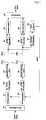
- FIG 3is a schematic diagram showing a D-STTD system applied to the present invention
- Figure 4is a flow chart showing a procedure for determining and feedbacking antenna pair determination information to be used in a transmitting end.
- the D-STTD system shown in Figure 3has the same configuration as the conventional D-STTD system shown in Figure 1 except an antenna separation and MCS selecting unit 111. It shows only different reference numerals therefrom.
- the antenna separation and MCS selecting unit 111determines an MCS to be used in the transmitting end and an antenna pair for an STTD transmission, and feedbacks the determined information to respective modulators 101 and 102 and respective STTD encoders 103 and 104 by a feedback signal.
- a receiving endcalculates a signal to interference noise ratio (SINR) with respect to every antenna pairs configuring an STTD pair to be transmittable from a transmitting end.
- SINRsignal to interference noise ratio
- the receiving endselects an antenna pair corresponding to the greatest SINR among calculated SINRs, namely, an antenna pair having the greatest instantaneous maximum reception data amount, and thereafter the receiving end feedbacks the information of the selected antenna pair together with the MCS to the transmitting end (steps S11 and S12). Therefore, the transmitting end performs a D-STTD transmission by using the MCS and the antenna pair (the STTD pair) determined by the information feedbacked from the receiving end (step S13).
- SINRsignal to interference noise ratio
- a channel matrix A ⁇ to be estimated in a channel predictor 110can be depicted as shown in Equation (4) herebelow.
- the antenna separation and MCS selecting unit 111obtains the SINR for each STTD pair as shown in Equations (5) and (6) by using an MMSE (Minimum Mean Square Error) reception algorithm with respect to the two STTD pairs.
- MMSEMinimum Mean Square Error
- the SINRrefers to a signal to interference noise ratio with respect to a data stream when setting T 1 x1 and Tx2 as an STTD pair
- the SINR 2refers to the signal to interference noise ratio with respect to a data stream when setting Tx3 and Tx4 as another STTD pair.
- s 2refers to Gaussian noise in the receive antenna
- Hrefers to a Hermitian operation of a vector formed of a complex number.
- Equation (4)indicates a channel matrix for obtaining the SINR when performing the D-STTD with the STTD pairs (1,2) and (3,4).
- Equation (6)a column sequence of the channel matrix shown in Equation (6) corresponds to (1,3,2,4) when the column sequence of the channel matrix shown in Equation (4) is (1,2,3,4). Therefore, in the channel matrix obtained when performing the D-STTD with the STTD pairs (1,3) and (2,4), because only the column sequence has been changed, the SINR for each STTD pair can be obtained by using Equations (5) and (6).
- the SINR of each data streamcan be obtained by changing a configuration of the channel matrix and then using the equations (Equations (5) and (6)) of the same SINR.
- the antenna separation and MCS selecting unit 111feedbacks the MCS method and the antenna pair determination information to the transmitting end.
- the MCSindicates the instantaneous maximum reception data amount receivable in the current receiving end.
- the antenna separation and MCS selecting unit 111obtains the SINR for each antenna pair (each STTD pair), and selects an antenna pair having the greatest instantaneous maximum reception data amount as an antenna pair for the transmit antennas, thereafter feedbacking it to the transmitting end.
- the feedbacked MCS informationis used in each modulator 31 and 32 and each STTD encoder 33 and 34 of the transmitting end for modulating and coding
- the antenna pair determination informationis used for distributing an output of each modulator 101 and 102 and each STTD encoder 103 and 104 to be suitable for each antenna pair.
- the receiving endperforms a suitable signal processing opposite to a signal processing of the transmitting end through the STTD decoders 105 and 106, the demodulators 107 and 108 and the multiplexer 109, thereby restoring an original data.
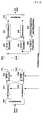
- FIG 5illustrates an example of the beamforming-combined STTD system according to the present invention.
- the STTD system shown in Figure 5has the same configuration as the conventional STTD system shown in Figure 2 except an operation of an MCS selecting unit 213. It shows only different reference numerals therefrom.
- the MCS selecting unit 213calculates an eigenvector corresponding to a maximum eigenvalue of a channel matrix estimated at a channel predictor 212, and thereafter feedbacks it together with the MCS to the transmitting end by a feedback signal.
- Equation (8)an actual channel matrix estimated at the channel predictor 212 can be indicated as shown in Equation (8) herebelow.
- H ⁇R ⁇ R 1 / 2 H ⁇ R ⁇ T 1 / 2
- R ⁇ R 1 / 2refers to a half-square matrix of a receiving correlation matrix configured with a corre lation value between receive antennas
- R ⁇ T 1 / 2refers to a half-square matrix of a transmitting correlation matrix configured with a correlation value between transmitting antennas
- H ⁇refers to a matrix configured with a channel value in a radio channel.
- an actual channel matrix H ⁇ ′ estimated at the receiving endincludes a correlation value between transmit antennas, a correlation value between receive antennas and a channel value in a radio channel circumstance all together, it is very hard to separate only the correlation value between the transmit antennas from the channel matrix H ⁇ ′
- the MCS selecting unit 213 of the receiving endcalculates a weight value for an STTD and beamforming of the transmitting end by using an eigenvalue and an eigenvector of the channel matrix to be actually estimated at the receiving end.
- the eigenvector of the channel matrix H ⁇ ′ to be actually estimated at the receiving endcan be used as the weight value for the beamforming of the transmitting end.
- the modulators 201 and 202 and the STTD encoders 203 and 204perform a modulation and an STTD with respect to a symbol (data stream) to be transmitted by using the MCS feedbacked from the receiving end.
- the beamforming units 205 and 206multiply the STTD-performed symbol by the eigenvector (weight value) feedbacked from the receiving end and perform the beamforming, thereafter transmitting it to each transmit antenna.
- the transmitting endcan transmit the symbol as a type that the STTD is combined with the beamforming as shown in Equation (9) herebelow.
- [ ⁇ 1 ⁇ 2 ] Trefers to eigenvectors corresponding to a maximum eigenvalue of the channel matrix H ⁇ ′ to be actually estimated at the receiving end
- ⁇ 1 and ⁇ 2( ⁇ 2 > ⁇ 1 ) are eigenvalues of H ⁇ ′
- E srefers to symbol energy
- ⁇ 2refers to energy of Gaussian noise.
- the method for transmitting a signal according to the present invention in the beamforming-combined STTD systemcan be applied even in case of using four or more antennas without a limitation on four transmit antennas.
- FIG 6illustrates another embodiment of the beamforming-combined STTD system.
- the STTD system shown in Figure 6is used in case of using more than four transmit antennas, and actually has the same configuration as the STTD system shown in Figure 5 except an antenna separation and MCS selecting unit 220.
- the antenna separation and MCS selecting unit 220performs a function for feedbacking a feedback signal (MCS), an eigenvector and antenna pair determination information to the modulators 201 and 202 and the beamforming units 205 and 206 of the transmitting end.
- MCSfeedback signal
- a symbol (signal) to be transmittedis demultiplexed at the demultiplexer 220 and then inputted to an STTD pair (each STTD pair includes the modulator, the STTD encoder and the beamforming unit).
- Each modulator 201 and 202 and each STTD encoder 203 and 204modulate and code the transmitted signal by using a modulation and a coding rate selected with reference to the MCS feedbacked from the receiving end.
- the beamforming units 205 and 206multiply the symbol which has been space-time coded (STTD-performed) at each STTD encoder 203 and 204 by the eigenvector feedbacked from the receiving end.
- the beamforming units 205 and 206then perform a beamforming, and thereafter transmit it to each transmit antenna pair.
- each STTD decoder 207 and 208 and each demodulator 209 and 210decode and demodulate the received signal by using the MCS and the eigenvector.
- the received signal demodulated at each demodulator 209 and 210is then converted into a serial data item at the multiplexer 211, and accordingly restored to an original symbol.
- the channel predictor 212 of the receiving endreceives the received signal and estimates a channel matrix to be actually estimated thereat.
- the antenna separation and MCS selecting unit 230feedbacks to the transmitting end the eigenvector corresponding to a maximum eigenvalue of the estimated channel matrix as a weight vector by the feedback signal.
- each beamforming unit 205 and 206performs the beamforming with respect to each antenna pair (1,2) and (3,4) as shown in Equation (9) above and Equation (10) herebelow.
- [ ⁇ 3 ⁇ 4 ] Trefers to an eigenvector corresponding to a maximum eigenvalue of a channel matrix to be actually estimated at the receiving end with respect to the transmit antenna (3,4) and is feedbacked at the receiving end.
- ⁇ 1 and ⁇ 2( ⁇ 2 > ⁇ 1 ) refer to eigenvalues of a channel matrix to be actually estimated at the receiving end corresponding to the transmit antenna (3, 4).
- the transmitting endhas the even number of transmit antennas
- the method for transmitting a signal in case of using two transmit antennascan be applied thereto as well.
- the STTD and beamformingare sequentially performed, and thus it is possible to reduce an amount of weight value to be feedbacked from the receiving end (a terminal).
- the antennascan be combined as various different pairs in addition to (1,2) and (3,4).
- the antenna separation and MCS selecting unit 220 of the receiving endcalculates the signal to interference noise ratio (SINR) with respect to every antenna pairs (channel matrixes to be estimated), and accordingly can feedback the transmit antenna pair having the greatest SINR, namely, the largest instantaneous maximum reception data amount, to the transmitting end.
- SINRsignal to interference noise ratio
- the antenna separation and MCS selecting unit 220configures a channel matrix corresponding to the selected antenna pair, and calculates and feedbacks a weight value for the beamforming.
- This method for transmitting a signaladopts advantages of the STTD as well as the beamforming, so as to be very effective when transmitting a plurality of data streams (symbols) independently.
- the antennascan be extended by setting them as a pair by two antennas, so that there is no problem of expandability thereof.
- an antenna pair configuring each STTD pair in order to receive the greatest signal to interference noise ratio at the receiving endcan be selected. As a result, it is effective to improve a data transmission speed compared with the existing method.
- the present inventionin case of using a plurality of antennas in the beamforming-combined STTD system, it is effective to improve a data transmission speed and a data receiving rate which are advantages of the STTD and the beamforming by setting them as a pair by two antennas and performing the STTD and the beamforming together thereby to transmit a plurality of data streams. Furthermore, for the weight vector in order to perform the beamforming, the eigenvector of the channel matrix to be estimated at the receiving end is used thereas, so that it can be appropriate for an actual application.
Landscapes
- Engineering & Computer Science (AREA)
- Computer Networks & Wireless Communication (AREA)
- Signal Processing (AREA)
- Physics & Mathematics (AREA)
- Mathematical Physics (AREA)
- Radio Transmission System (AREA)
- Mobile Radio Communication Systems (AREA)
Description
- The present invention relates to a method for transmitting a signal in a mobile comnunications system, and particularly, to a method for transmitting a signal in an MIMO system using a plurality of transmit/receive antennas.
- Recently, IMT-2000 system based on a third generation partnership project (3GPP) of W-CDMA wireless specification has adopted a space time transmit diversity (STTD) as an open loop type transmit diversity technique. The STTD refers to a technique for achieving a diversity advantage through a space-time coding extending a channel coding usually applied in a time base to a space based.
- The STTD can be applied to every downlink physical channels except a synchronization channel (SCH) of WCDMA, in which there is no need for feedback information transmitted from a receiving end to a transmitting end, and accordingly it is advantageous to have diversity of system performances according to variation of speed and a radio channel.
- The STTD technique uses two transmit antennas and a single receive antenna, by which diversity advantages of space and time can be achieved together by simply performing a space-time coding with respect to symbols transmitted through the two antennas. For this purpose, the conventional STTD system requires two transmit antennas and a space-time coding block (namely, an STTD encoder) in order to code symbols therebetween transmitted through the two transmit antennas. The STTD is operated as can be seen from [Table 1].
[Table 1] Timet Timet+T Antenna 1 S1 S2 Antenna 2 

- Here, the mark'*' denotes a conjugate.
- Referring to [Table 1], symbols to be transmitted are encoded in the STTD encoder and transmitted to Antenna 1 and Antenna 2, respectively, according to time sequence. The signals transmitted to the respective antennas go through independent channels different from each other. Assuming that a channel in a time t is identical to a channel in a time t + T (T refers to a symbol period), received signals r , r of the receiving end 1 2 can be shown in Equation (1) herebelow.

- Here,

- Therefore, once combining the two received signals r , r therewith in the receiving 1 2 end as shown in Equation (2), it is possible to obtain the same value as an MRC (Maximum Ratio Combining) method of a receiving diversity. On the basis of this, the transmission symbol can be estimated.

- A double STTD (hereinafter, refer to D-STTD) is a method obtained by enlarging the STTD technique using only two transmit antennas to an MIMO (Multi Input Multi Output) system. Here, the D-STTD system using four transmit antennas can include two STTD pairs.
- The D-STTD system has been first proposed in the 3GPP by Texas Instrument. After then, an antenna shuffling has been also proposed. In this antenna shuffling, different modulation methods (QPSK, QAM and the like) are applied to each STTD pair and the receiving end measures correlation between transmit antennas, thereby determining an STTD antenna pair. Furthermore, Mitsubishi Electric has been once proposed Sub group rate control D-STTD capable of applying an MCS (modulation and coding set) different from each other to the each STTD pair.
Figure 1 is a schematic diagram showing a D-STTD system of the related art.- With reference to
Figure 1 , data to be transmitted through the D-STTD system is separated in ademultiplexer 10 as a signal for two STTD pairs (each STTD pair includes a modulator, an STTD encoder and an antenna). Themodulators STTD encoders respective modulators respective STTD encoders respective STTD encoders modulator STTD decoders demodulators respective demodulators multiplexer 19 and thereby recovered to the original data.- On the other hand, a
channel predictor 20 of the receiving end receives the received signal and estimates a D-STTD channel matrix. AnMCS selecting unit 21 calculates a signal to interference noise ratio (SINR) of each data stream on the basis of the estimated D-STTD channel matrix, and accordingly selects a proper MCS corresponding to the SINR of each data stream, thereafter feedbacking it to the transmitting end. Figure 2 is a schematic diagram showing an STTD system combined with a beamforming of the related art. As can be seen fromFigure 2 , the D-STTD system additionally includes beamforming units 22 and 23, which can be applied when using only two transmit antennas.- Referring to
Figure 2 , first, data (a signal) to be transmitted is demultiplexed at thedemultiplexer 30 and then inputted to eachmodulator modulator STTD encoder STTD encoders respective modulators Beamforming units STTD encoder 
- Here, [w1 w2]Trefers to an eigenvector corresponding to a maximum eigenvalue of a half square matrix


- Therefore, because the receiving end has already known of the MCS and eigenvector values w1 and w2, the
respective STTD decoders respective demodulators respective demodulators multiplexer 41, and accordingly restored to an original data stream. - During this, the
channel predictor 42 of the receiving end receives the received signal and estimates an STTD channel matrix. AnMCS selecting unit 43 then calculates a signal to interference noise ratio (SINR) of each data stream depending on the estimated STTD channel matrix, and then selects an MCS corresponding to the SINR of each data stream, thereafter feedbacking it to the transmitting end. - As aforementioned, in the D-STTD system of the related art, in case that there are more than four transmit antennas therein, the transmit antennas are bound as two antenna pairs, and a plurality of data streams are transmitted through the corresponding antenna pair.
- However, there exists a degree of correlation between the transmit antennas, it is not preferable to simply set the two adjacent antennas as a pair for an STTD encoding. Therefore, once obtaining the correlation between the transmit antennas directly in the receiving end, information to determine a transmit antenna pair can be feedbacked to the transmitting end. However, in case of using this method, it is very difficult for the receiving end to obtain the correlation between the transmit antennas, and accordingly the method may also be actually difficult to be applied.
- In addition, as aforementioned, in the STTD system combined with the beamforming of the related art, in case that there are two transmit antennas, after performing the beamforming by multiplying the STTD-encoded data by the eigenvector, it is transmitted through each transmit antenna. However, this method for transmitting a signal is a signal processing method adopted only in case of using two transmit antennas, so that it is hard to be applied as it is when using more than two transmit antennas.
- Furthermore, in the method for transmitting a signal combined with the beamforming, the eigenvector corresponding to the maximum eigenvalue of the half square matrix of the correlation matrix (configuring the correlation value between the transmit antennas as a matrix) is used as a weight value for the beamforming. However, obtaining the value of the correlation matrix of the transmitting end is actually very difficult, so that the STTD combined with the beamforming of the related art can not be easily applied.
- That is, in the related art, in case of using two transmit antennas in the STTD system, the eigenvector has been used as the weight value to be used for the beamforming in condition that it is possible to obtain the eigenvector corresponding to the maximum eigenvalue of the correlation matrix configured with the correlation value between transmit antennas.
- By the way, because the channel matrix measured by the receiving end includes the correlation value between transmit antennas, the correlation value between receive antennas, and a channel value in a radio channel circumstance all together, it is actually very hard to separate only the correlation value between the transmit antennas from the channel matrix. Furthermore, the correlation value between the transmit antennas in an actual circumstance can be varied depending on time. The method for obtaining the weight value by using the correlation value between the transmit antennas of the related art may thus be hard to be actually applied.
- Moreover, in case that there are one or more receiving end antennas, the correlation value between the receiving end antennas should be considered, but the method for transmitting a signal of the related art only considers the correlation between transmit antennas. As a result, it is not an actually proper method for application.
US 2003/181170 A1 relates to apparatus and method for transmitting a signal in a mobile communication system.- A 3GPP Draft entitled "Improved Double-STTD Schemes Using Asymmetric Modulation and Antenna Shuffling" proposes further improvements to the Double-STTD for HSDPA applications by employing asymmetric modulation and antenna shuffling.
- Therefore, an object of the present invention is to provide a method for transmitting a signal capable of improving data transmission speed and a receiving rate in a D-STTD system and a system with which beamforming is combined.
- Another object of the present invention is to provide a method for transmitting a signal for feedbacking information to determine a transmit antenna pair from a receiving end to a transmitting end during a D-STTD transmission.
- Still another object of the present invention is to provide a method for transmitting a signal for applying more efficiently an STTD method with which beamforming is combined.
- Yet another object of the present invention is to provide a method for transmitting a signal for performing a space-time multiplexing (STTD) and a beamforming by each antenna pair.
- The present invention provides a method for communicating a signal according to independent claim 1. Various improvements to the method are recited in the dependent claims.
- Preferably, the channel matrix includes a correlation value between transmit antennas, a correlation value between receive antennas and a channel value in a radio channel circumstance all together.
- Preferably, the eigenvector is feedbacked from the receiving end to the transmitting end, and corresponds to a maximum eigenvalue of the channel matrix calculated at the receiving end.
- According to still another embodiment of the present invention, there is provided a method for transmitting a signal, in a system for performing a space-time multiplexing and a beamforming with respect to a transmission symbol, the method comprising the steps of: calculating an eigenvector of a channel matrix of a transmit antenna pair which has the greatest instantaneous maximum reception data amount and accordingly feedbacking it to a transmitting end; and performing in the transmitting end a beamforming with respect to the transmission symbol STTD-performed by an antenna pair, by using the feedbacked eigenvector as a weight vector.
- Preferably, the weight vector is an eigenvector of an actual channel matrix with respect to each antenna pair.
- Preferably, the channel matrix includes a correlation value between transmit antennas, a correlation value between receive antennas and a channel value in a radio channel circumstance all together.
- Preferably, the transmit antenna pair is an antenna pair having the greatest signal to interference noise ratio (SINR).
- The foregoing and other objects, features, aspects and advantages of the present invention will become more apparent from the following detailed description of the present invention when taken in conjunction with the accompanying drawings.
- The accompanying drawings, which are included to provide a further understanding of the invention and are incorporated in and constitute a part of this specification, illustrate embodiments of the invention and together with the description serve to explain the principles of the invention.
- In the drawings:
Figure 1 is a schematic diagram showing a D-STTD system of the related art;Figure 2 is a schematic diagram showing an STTD system with which a beamforming is combined of the related art;Figure 3 is a schematic diagram showing a D-STTD system applied to the present invention;Figure 4 is a flow chart showing how to transmit a signal in a D-STTD system according to the present invention;Figure 5 is a schematic diagram showing an embodiment of an STTD system, with which a beamforming is combined, applied to the present invention; andFigure 6 is a schematic diagram showing another embodiment of the STTD system, with which the beamforming is combined, applied to the present invention.- Reference will now be made in detail to the preferred embodiments of the present invention, examples of which are illustrated in the accompanying drawings.
- There is proposed a method for transmitting a signal in a mobile communications system using a plurality of transmit antennas and receive antennas, for instance, a D-STTD system, an STTD system with which a beamforming is combined, or the like. For this purpose, a transmitting end having a plurality of transmit antennas receives from a receiving end MCS information, determination information of an STTD pair (an antenna pair) and/or an eigenvector by a feedback signal, and accordingly performs a D-STTD transmission or a beamforming.
- Preferably, the feedback signal may be predetermined by an agreement between transmitting and receiving ends. Also, the MCS information to be used in the determined antenna pair is transmitted by using separate feedback information. The MCS information should be predetermined at the transmitting end and the receiving end and have the number of respective cases as a table type. Furthermore, it is possible to form a designated feedback information table by using the feedback information with respect to the determined antenna pair and the MCS information to be used in each antenna.
- First, according to an embodiment of the present invention, a method for transmitting a signal proposes a method in a D-STTD system, in which a receiving end determines an STTD pair (an antenna pair) to thereafter feedback it to a transmitting end, and the transmitting end performs a symbol transmission according to the feedbacked information. For this purpose, the receiving end estimates a channel of each transmit antenna to thereafter calculate a signal to interference noise ratio (SINR) with respect to each STTD pair. According to this, the receiving end then determines an antenna pair having the greatest SINR, thereby feedbacking it to the transmitting end.
- According to another embodiment of the present invention, a method for transmitting a signal proposes a method for calculating a weight value for performing a beamforming in an STTD system with which a beamforming is combined, and particularly, a method for efficiently applying the beanforming-combined STTD method in case that there are two or more transmit antennas. For this purpose, a receiving end of the present invention estimates a channel matrix including correlation between transmit antennas, a channel condition under a radio circumstance and correlation between receive antennas all together. Then, the receiving end feedbacks an eigenvector corresponding to a maximum eigenvalue of the estimated channel matrix as a weight value required for a beamforming of a transmitting end.
- Furthermore, in the present invention, when there are two or more transmit antennas in the beamforming-combined STTD system, a transmit antenna pair is formed, and then a space-time multiplexing (STTD) and a beamforming are performed with respect to a symbol to be transmitted through each transmit antenna pair.
- First, it will be explained how to feedback antenna pair determination information in a D-STTD system.
Figure 3 is a schematic diagram showing a D-STTD system applied to the present invention,Figure 4 is a flow chart showing a procedure for determining and feedbacking antenna pair determination information to be used in a transmitting end. The D-STTD system shown inFigure 3 , has the same configuration as the conventional D-STTD system shown inFigure 1 except an antenna separation andMCS selecting unit 111. It shows only different reference numerals therefrom.- The antenna separation and
MCS selecting unit 111 determines an MCS to be used in the transmitting end and an antenna pair for an STTD transmission, and feedbacks the determined information torespective modulators respective STTD encoders - Referring to
Figures 3 and4 , in the D-STTD system, a receiving end calculates a signal to interference noise ratio (SINR) with respect to every antenna pairs configuring an STTD pair to be transmittable from a transmitting end. Once having calculated the SINR, the receiving end selects an antenna pair corresponding to the greatest SINR among calculated SINRs, namely, an antenna pair having the greatest instantaneous maximum reception data amount, and thereafter the receiving end feedbacks the information of the selected antenna pair together with the MCS to the transmitting end (steps S11 and S12). Therefore, the transmitting end performs a D-STTD transmission by using the MCS and the antenna pair (the STTD pair) determined by the information feedbacked from the receiving end (step S13). - For instance, assuming that the D-STTD system shown in
Figure 3 uses four transmit antennas (TX1∼TX4) and a receive antenna (Rx) and h11, h12, h13, and h are channels between each transmit antenna (TX1∼TX4) and the receive antenna (Rx). A channel matrix
channel predictor 110 can be depicted as shown in Equation (4) herebelow.
- At this time, since two STTD pairs can be formed with respect to the four transmit antennas (TX1∼TX4), as can be seen from
Figures 1 and2 , the antenna separation andMCS selecting unit 111 obtains the SINR for each STTD pair as shown in Equations (5) and (6) by using an MMSE (Minimum Mean Square Error) reception algorithm with respect to the two STTD pairs.

- TheSINR refers to a signal to interference noise ratio with respect to a data stream when setting T1x1 and Tx2 as an STTD pair, while theSINR2 refers to the signal to interference noise ratio with respect to a data stream when setting Tx3 and Tx4 as another STTD pair. Also, in those Equations, s2refers to Gaussian noise in the receive antenna, and H refers to a Hermitian operation of a vector formed of a complex number.
- Here, assuming that (1, 2) denotes the STTD pair for Tx1 and Tx2, and (3,4) denotes the STTD pair for Tx3 and Tx4, a configuration of the channel matrix of Equation (4) indicates a channel matrix for obtaining the SINR when performing the D-STTD with the STTD pairs (1,2) and (3,4).
- Thus, in case of performing the D-STTD with the STTD pairs (1,3) and (2,4), the channel matrix is configured as shown in Equation (7) herebelow, and thereafter the SINR can be obtained by using Equations (5) and (6).

- That is, a column sequence of the channel matrix shown in Equation (6) corresponds to (1,3,2,4) when the column sequence of the channel matrix shown in Equation (4) is (1,2,3,4). Therefore, in the channel matrix obtained when performing the D-STTD with the STTD pairs (1,3) and (2,4), because only the column sequence has been changed, the SINR for each STTD pair can be obtained by using Equations (5) and (6).
- Using the same method, with respect to the STTD pairs such as (1,4) (2,3) / (1,2) (4,3) / (1,3) (4,2) / (1,4) (3,2), the SINR of each data stream can be obtained by changing a configuration of the channel matrix and then using the equations (Equations (5) and (6)) of the same SINR.
- By using this obtained SINR, the antenna separation and
MCS selecting unit 111 feedbacks the MCS method and the antenna pair determination information to the transmitting end. In this case, the MCS indicates the instantaneous maximum reception data amount receivable in the current receiving end. - However, because the channel condition is continually changed, the instantaneous maximum reception data amount receivable in the receiving end is also changed. Therefore, the antenna separation and
MCS selecting unit 111 obtains the SINR for each antenna pair (each STTD pair), and selects an antenna pair having the greatest instantaneous maximum reception data amount as an antenna pair for the transmit antennas, thereafter feedbacking it to the transmitting end. - Thus, the feedbacked MCS information is used in each modulator 31 and 32 and each
STTD encoder STTD encoder STTD decoders demodulators multiplexer 109, thereby restoring an original data. Figure 5 illustrates an example of the beamforming-combined STTD system according to the present invention. The STTD system shown inFigure 5 has the same configuration as the conventional STTD system shown inFigure 2 except an operation of anMCS selecting unit 213. It shows only different reference numerals therefrom.- The
MCS selecting unit 213 calculates an eigenvector corresponding to a maximum eigenvalue of a channel matrix estimated at achannel predictor 212, and thereafter feedbacks it together with the MCS to the transmitting end by a feedback signal. - Referring to
Figure 5 , an actual channel matrix estimated at thechannel predictor 212 can be indicated as shown in Equation (8) herebelow.
- Here,


- However, because an actual channel matrix


- Therefore, the
MCS selecting unit 213 of the receiving end calculates a weight value for an STTD and beamforming of the transmitting end by using an eigenvalue and an eigenvector of the channel matrix to be actually estimated at the receiving end. In the present invention, the eigenvector of the channel matrix
- Accordingly, the
modulators STTD encoders beamforming units - For instance, in case that there are two transmit antennas, the transmitting end can transmit the symbol as a type that the STTD is combined with the beamforming as shown in Equation (9) herebelow.

- Here, [α1 α2]T refers to eigenvectors corresponding to a maximum eigenvalue of the channel matrix


- In addition, the method for transmitting a signal according to the present invention in the beamforming-combined STTD system can be applied even in case of using four or more antennas without a limitation on four transmit antennas.
Figure 6 illustrates another embodiment of the beamforming-combined STTD system. The STTD system shown inFigure 6 is used in case of using more than four transmit antennas, and actually has the same configuration as the STTD system shown inFigure 5 except an antenna separation andMCS selecting unit 220.- The antenna separation and
MCS selecting unit 220 performs a function for feedbacking a feedback signal (MCS), an eigenvector and antenna pair determination information to themodulators beamforming units - Referring to
Figure 6 , a symbol (signal) to be transmitted is demultiplexed at thedemultiplexer 220 and then inputted to an STTD pair (each STTD pair includes the modulator, the STTD encoder and the beamforming unit). Eachmodulator STTD encoder beamforming units STTD encoder beamforming units - Because the receiving end has already known of the MCS and the eigenvector, each
STTD decoder multiplexer 211, and accordingly restored to an original symbol. - During this, the
channel predictor 212 of the receiving end receives the received signal and estimates a channel matrix to be actually estimated thereat. The antenna separation and MCS selecting unit 230 feedbacks to the transmitting end the eigenvector corresponding to a maximum eigenvalue of the estimated channel matrix as a weight vector by the feedback signal. - Still referring to
Figure 6 , in case of transmitting a symbol (stream) by using more than four transmit antennas, the present invention performs an STTD and a beamforming for each transmit antenna pair. That is, in case that there are four transmit antennas, eachbeamforming unit 
- Here, [α3 α4]T refers to an eigenvector corresponding to a maximum eigenvalue of a channel matrix to be actually estimated at the receiving end with respect to the transmit antenna (3,4) and is feedbacked at the receiving end. γ may be defined as

- Therefore, in case that the transmitting end has the even number of transmit antennas, if a signal is transmitted by performing an STTD and a beamforming with setting two transmit antenna pairs, the method for transmitting a signal in case of using two transmit antennas can be applied thereto as well. In particular, in case of using more than four antennas, after setting the four antennas as two antenna pairs, the STTD and beamforming are sequentially performed, and thus it is possible to reduce an amount of weight value to be feedbacked from the receiving end (a terminal).
- That is, in case of using four transmit antennas, once performing the STTD first, a signal is transmitted through two antenna pairs. As a result of this, two data streams can be transmitted at the same time, and there are only four (α1, α2, α3, α4) weight values to be feedbacked at the receiving end. However, in case that independent data streams are transmitted through the respective four antennas, because of multiplying a signal to be transmitted by four weight vectors of which dimension is 4x1, the receiving end should feedback totally 16 complex number values (eigenvalues) to the transmitting end. Whereas, in the present invention, because of multiplying each different STTD pair by two weight vectors of which dimension is 2x1, the receiving end should only feedback two weight vectors of which dimension is 2x1 to the transmitting end.
- Therefore, when using more than four transmit antennas, after setting the four antennas as two pairs and performing the STTD, if the beamforming is performed with respect to each antenna pair, only two complex values with respect to each antenna pair is being feedbacked, so that the amount of feedback information can be remarkably reduced.
- Furthermore, in case of performing the STTD and beamforming using four antennas, the antennas can be combined as various different pairs in addition to (1,2) and (3,4). Accordingly, the antenna separation and
MCS selecting unit 220 of the receiving end, as shown inFigure 4 , calculates the signal to interference noise ratio (SINR) with respect to every antenna pairs (channel matrixes to be estimated), and accordingly can feedback the transmit antenna pair having the greatest SINR, namely, the largest instantaneous maximum reception data amount, to the transmitting end. During this, the antenna separation andMCS selecting unit 220 configures a channel matrix corresponding to the selected antenna pair, and calculates and feedbacks a weight value for the beamforming. - This method for transmitting a signal adopts advantages of the STTD as well as the beamforming, so as to be very effective when transmitting a plurality of data streams (symbols) independently. In the present invention, it has been explained of an example for the case of using four transmit antennas. Although more than four transmit antennas are used, the antennas can be extended by setting them as a pair by two antennas, so that there is no problem of expandability thereof.
- As described above, in the present invention, by calculating the signal to interference noise ratio at the receiving end, an antenna pair configuring each STTD pair in order to receive the greatest signal to interference noise ratio at the receiving end can be selected. As a result, it is effective to improve a data transmission speed compared with the existing method.
- In the present invention, in case of using a plurality of antennas in the beamforming-combined STTD system, it is effective to improve a data transmission speed and a data receiving rate which are advantages of the STTD and the beamforming by setting them as a pair by two antennas and performing the STTD and the beamforming together thereby to transmit a plurality of data streams. Furthermore, for the weight vector in order to perform the beamforming, the eigenvector of the channel matrix to be estimated at the receiving end is used thereas, so that it can be appropriate for an actual application.


Claims (6)
- A method for communicating a signal in a system for transmitting a symbol for which a space-time multiplexing (STTD) and a beamforming have been performed by a transmitting end having more than four transmit antennas, the method comprising the steps of:calculating a signal to interference noise ratio (SINR) with respect to transmit antenna pairs;determining two antenna pairs at least one of which has the greatest SINR among the respective antenna pairs;calculating an eigenvector of a channel matrix with respect to the determined antenna pair;feedbacking the antenna pair determination information and the eigenvector to the transmitting end; andreceiving a symbol for which a beamforming and an STTD have been performed according to the two determined antenna pairs by using the eigenvector as a weight vector,wherein the channel matrix comprises a correlation value between the more than four transmit antennas, a correlation value between receive antennas, and a channel value in a radio channel circumstance.
- The method of claim 1, wherein at least one of the two antenna pairs has the largest instantaneous maximum reception data amount.
- The method of claim 1, wherein the antenna pair determination information is transmitted by a separate feedback signal designated between transmitting and receiving ends.
- The method of claim 1, wherein the antenna pair determination information can be combined with other information designated between the transmitting and receiving ends to thereafter be transmitted.
- The method of claim 4, wherein the other information is a modulation and coding set (MCS) to be used in each antenna pair.
- The method of claim 4, wherein the two information are managed and transmitted as a table type.
Applications Claiming Priority (5)
| Application Number | Priority Date | Filing Date | Title |
|---|---|---|---|
| US53771404P | 2004-01-20 | 2004-01-20 | |
| KR1020040008446AKR20050080369A (en) | 2004-02-09 | 2004-02-09 | Method for transmitting signal using plurality of transmission/reception antennas in mobile communication system |
| KR1020040008450AKR20050080372A (en) | 2004-02-09 | 2004-02-09 | Method for transmitting signal using plurality of transmission/reception antennas in mobile communication system |
| US54593404P | 2004-02-20 | 2004-02-20 | |
| PCT/KR2005/000164WO2005069505A1 (en) | 2004-01-20 | 2005-01-18 | Method for transmitting/receiving signal in mimo system |
Publications (3)
| Publication Number | Publication Date |
|---|---|
| EP1709752A1 EP1709752A1 (en) | 2006-10-11 |
| EP1709752A4 EP1709752A4 (en) | 2012-02-01 |
| EP1709752B1true EP1709752B1 (en) | 2016-09-14 |
Family
ID=36955089
Family Applications (1)
| Application Number | Title | Priority Date | Filing Date |
|---|---|---|---|
| EP05721817.4AExpired - LifetimeEP1709752B1 (en) | 2004-01-20 | 2005-01-18 | Method for transmitting/receiving signals in a mimo system |
Country Status (7)
| Country | Link |
|---|---|
| US (2) | US7623587B2 (en) |
| EP (1) | EP1709752B1 (en) |
| JP (1) | JP2007518346A (en) |
| KR (1) | KR100850990B1 (en) |
| BR (1) | BRPI0506904A (en) |
| HR (1) | HRP20060253A2 (en) |
| WO (1) | WO2005069505A1 (en) |
Families Citing this family (92)
| Publication number | Priority date | Publication date | Assignee | Title |
|---|---|---|---|---|
| US9130810B2 (en) | 2000-09-13 | 2015-09-08 | Qualcomm Incorporated | OFDM communications methods and apparatus |
| US7295509B2 (en) | 2000-09-13 | 2007-11-13 | Qualcomm, Incorporated | Signaling method in an OFDM multiple access system |
| WO2005076758A2 (en)* | 2004-02-11 | 2005-08-25 | Lg Electronics Inc. | A method and system for transmitting and receiving data streams |
| CN101764633B (en)* | 2004-02-11 | 2016-08-17 | Lg电子株式会社 | Launch and receive the method and system of data stream |
| US7710925B2 (en)* | 2004-06-23 | 2010-05-04 | Intel Corporation | Spatial puncturing apparatus, method, and system |
| US9148256B2 (en) | 2004-07-21 | 2015-09-29 | Qualcomm Incorporated | Performance based rank prediction for MIMO design |
| US9137822B2 (en) | 2004-07-21 | 2015-09-15 | Qualcomm Incorporated | Efficient signaling over access channel |
| FI20041311A0 (en)* | 2004-10-08 | 2004-10-08 | Nokia Corp | Lohkomodulaatio |
| KR101023366B1 (en)* | 2004-10-27 | 2011-03-18 | 삼성전자주식회사 | Apparatus and method for transmitting / receiving signals in a multiple input multiple output wireless communication system using a beamforming method |
| CN1797987B (en)* | 2004-12-30 | 2011-02-16 | 都科摩(北京)通信技术研究中心有限公司 | Communication system for self-adaptive scheduling MIMO, and method for self-adaptive scheduling users |
| US8515359B2 (en)* | 2005-03-09 | 2013-08-20 | Intel Corporation | Method and apparatus to provide low cost transmit beamforming for network devices |
| US9246560B2 (en) | 2005-03-10 | 2016-01-26 | Qualcomm Incorporated | Systems and methods for beamforming and rate control in a multi-input multi-output communication systems |
| US8995547B2 (en)* | 2005-03-11 | 2015-03-31 | Qualcomm Incorporated | Systems and methods for reducing uplink resources to provide channel performance feedback for adjustment of downlink MIMO channel data rates |
| US8724740B2 (en)* | 2005-03-11 | 2014-05-13 | Qualcomm Incorporated | Systems and methods for reducing uplink resources to provide channel performance feedback for adjustment of downlink MIMO channel data rates |
| US9154211B2 (en) | 2005-03-11 | 2015-10-06 | Qualcomm Incorporated | Systems and methods for beamforming feedback in multi antenna communication systems |
| US8446892B2 (en) | 2005-03-16 | 2013-05-21 | Qualcomm Incorporated | Channel structures for a quasi-orthogonal multiple-access communication system |
| US9461859B2 (en) | 2005-03-17 | 2016-10-04 | Qualcomm Incorporated | Pilot signal transmission for an orthogonal frequency division wireless communication system |
| US9520972B2 (en) | 2005-03-17 | 2016-12-13 | Qualcomm Incorporated | Pilot signal transmission for an orthogonal frequency division wireless communication system |
| US9143305B2 (en) | 2005-03-17 | 2015-09-22 | Qualcomm Incorporated | Pilot signal transmission for an orthogonal frequency division wireless communication system |
| US9184870B2 (en) | 2005-04-01 | 2015-11-10 | Qualcomm Incorporated | Systems and methods for control channel signaling |
| US9036538B2 (en) | 2005-04-19 | 2015-05-19 | Qualcomm Incorporated | Frequency hopping design for single carrier FDMA systems |
| US9408220B2 (en) | 2005-04-19 | 2016-08-02 | Qualcomm Incorporated | Channel quality reporting for adaptive sectorization |
| US8879511B2 (en) | 2005-10-27 | 2014-11-04 | Qualcomm Incorporated | Assignment acknowledgement for a wireless communication system |
| US8565194B2 (en) | 2005-10-27 | 2013-10-22 | Qualcomm Incorporated | Puncturing signaling channel for a wireless communication system |
| US8611284B2 (en) | 2005-05-31 | 2013-12-17 | Qualcomm Incorporated | Use of supplemental assignments to decrement resources |
| US8462859B2 (en) | 2005-06-01 | 2013-06-11 | Qualcomm Incorporated | Sphere decoding apparatus |
| US8599945B2 (en) | 2005-06-16 | 2013-12-03 | Qualcomm Incorporated | Robust rank prediction for a MIMO system |
| US9179319B2 (en) | 2005-06-16 | 2015-11-03 | Qualcomm Incorporated | Adaptive sectorization in cellular systems |
| US8885628B2 (en) | 2005-08-08 | 2014-11-11 | Qualcomm Incorporated | Code division multiplexing in a single-carrier frequency division multiple access system |
| US20070041457A1 (en) | 2005-08-22 | 2007-02-22 | Tamer Kadous | Method and apparatus for providing antenna diversity in a wireless communication system |
| US9209956B2 (en) | 2005-08-22 | 2015-12-08 | Qualcomm Incorporated | Segment sensitive scheduling |
| US8073068B2 (en)* | 2005-08-22 | 2011-12-06 | Qualcomm Incorporated | Selective virtual antenna transmission |
| US8644292B2 (en) | 2005-08-24 | 2014-02-04 | Qualcomm Incorporated | Varied transmission time intervals for wireless communication system |
| US9136974B2 (en) | 2005-08-30 | 2015-09-15 | Qualcomm Incorporated | Precoding and SDMA support |
| FI20055483A0 (en)* | 2005-09-08 | 2005-09-08 | Nokia Corp | Data transmission system in wireless communication system |
| WO2007028864A1 (en)* | 2005-09-08 | 2007-03-15 | Nokia Corporation | Data transmission scheme in wireless communication system |
| US7936808B2 (en)* | 2005-09-21 | 2011-05-03 | Broadcom Corporation | Channel quantization for multiuser diversity |
| US9210651B2 (en) | 2005-10-27 | 2015-12-08 | Qualcomm Incorporated | Method and apparatus for bootstraping information in a communication system |
| US8582509B2 (en) | 2005-10-27 | 2013-11-12 | Qualcomm Incorporated | Scalable frequency band operation in wireless communication systems |
| US9172453B2 (en) | 2005-10-27 | 2015-10-27 | Qualcomm Incorporated | Method and apparatus for pre-coding frequency division duplexing system |
| US8045512B2 (en) | 2005-10-27 | 2011-10-25 | Qualcomm Incorporated | Scalable frequency band operation in wireless communication systems |
| US9225488B2 (en) | 2005-10-27 | 2015-12-29 | Qualcomm Incorporated | Shared signaling channel |
| US9088384B2 (en) | 2005-10-27 | 2015-07-21 | Qualcomm Incorporated | Pilot symbol transmission in wireless communication systems |
| US9225416B2 (en) | 2005-10-27 | 2015-12-29 | Qualcomm Incorporated | Varied signaling channels for a reverse link in a wireless communication system |
| US8693405B2 (en) | 2005-10-27 | 2014-04-08 | Qualcomm Incorporated | SDMA resource management |
| US8477684B2 (en) | 2005-10-27 | 2013-07-02 | Qualcomm Incorporated | Acknowledgement of control messages in a wireless communication system |
| US9144060B2 (en) | 2005-10-27 | 2015-09-22 | Qualcomm Incorporated | Resource allocation for shared signaling channels |
| JP4852984B2 (en)* | 2005-11-09 | 2012-01-11 | 株式会社日立製作所 | Multi-channel transmission system using multiple base stations |
| US8582548B2 (en) | 2005-11-18 | 2013-11-12 | Qualcomm Incorporated | Frequency division multiple access schemes for wireless communication |
| US8102830B2 (en)* | 2005-12-16 | 2012-01-24 | Samsung Electronics Co., Ltd. | MIMO radio communication apparatus and method |
| TWI431990B (en) | 2006-01-11 | 2014-03-21 | Interdigital Tech Corp | Method and apparatus for implementing space time processing with unequal modulation and coding schemes |
| KR100950654B1 (en)* | 2006-03-03 | 2010-04-01 | 삼성전자주식회사 | Signal transceiving device and method in communication system using multiple input multiple output method |
| US8036257B2 (en)* | 2006-05-05 | 2011-10-11 | Alcatel Lucent | Method of determining at least one transmit mode parameter for a multiple-input multiple-output system |
| US7974360B2 (en) | 2006-05-24 | 2011-07-05 | Qualcomm Incorporated | Multi input multi output (MIMO) orthogonal frequency division multiple access (OFDMA) communication system |
| JP2008017096A (en) | 2006-07-05 | 2008-01-24 | Fujitsu Ltd | COMMUNICATION SYSTEM FOR TRANSMITTING / RECEIVING BY MULTIPLE ANTENNA |
| US8738103B2 (en)* | 2006-07-18 | 2014-05-27 | Fractus, S.A. | Multiple-body-configuration multimedia and smartphone multifunction wireless devices |
| EP2547003B1 (en)* | 2006-09-06 | 2014-10-15 | Qualcomm Incorporated | Codeword permutation and reduced feedback for grouped antennas |
| CN1968041B (en)* | 2006-09-19 | 2012-01-18 | 北京邮电大学 | Method for enhancing incepting performance of practice MIMO system |
| US8073486B2 (en)* | 2006-09-27 | 2011-12-06 | Apple Inc. | Methods for opportunistic multi-user beamforming in collaborative MIMO-SDMA |
| US8670504B2 (en)* | 2006-12-19 | 2014-03-11 | Qualcomm Incorporated | Beamspace-time coding based on channel quality feedback |
| US9106296B2 (en)* | 2006-12-19 | 2015-08-11 | Qualcomm Incorporated | Beam space time coding and transmit diversity |
| KR100957854B1 (en) | 2007-01-30 | 2010-05-14 | 고려대학교 산학협력단 | Method and apparatus for transmitting and receiving signal in communication system |
| WO2008112862A1 (en)* | 2007-03-13 | 2008-09-18 | Nec Laboratories America, Inc. | Group lmmse demodulation using noise and interference covariance matrix for reception on a cellular downlink |
| US7843990B2 (en)* | 2007-04-09 | 2010-11-30 | Alcatel-Lucent Usa Inc. | Determining a channel matrix by measuring interference |
| US8054837B2 (en) | 2007-04-30 | 2011-11-08 | Yim Tu Investments Ltd., Llc | Multiuser scheduling for MIMO broadcast channels with finite rate feedback |
| EP2003808B1 (en)* | 2007-06-15 | 2013-09-18 | Motorola Mobility LLC | Apparatus for space time coding using training symbols to provide transmission range extension |
| US8798202B2 (en)* | 2007-06-15 | 2014-08-05 | Motorola Mobility Llc | Method and apparatus using sounding PPDUs to provide range extension to IEEE 802.11n signals |
| EP2007026B1 (en) | 2007-06-19 | 2012-01-11 | Alcatel Lucent | Method for transmitting symbols encoded in a hybrid MIMO transceiver scheme, transmitter,receiver, and MIMO system |
| KR101387538B1 (en)* | 2007-10-26 | 2014-04-21 | 엘지전자 주식회사 | Method of transmitting a antenna control signal |
| KR20090071796A (en)* | 2007-12-28 | 2009-07-02 | 삼성전자주식회사 | Channel information feedback apparatus and method in a multi-antenna system |
| WO2009084877A1 (en)* | 2007-12-28 | 2009-07-09 | Samsung Electronics Co., Ltd. | Method and apparatus for transmitting/receiving downlink data in wireless communication network |
| US20090186590A1 (en)* | 2008-01-18 | 2009-07-23 | Nortel Netowrks Limited | Method for Channel Calibration |
| WO2009087591A2 (en)* | 2008-01-07 | 2009-07-16 | Runcom Technologies Ltd. | Cinr formula for spatial multiplexing |
| JP5009826B2 (en)* | 2008-01-30 | 2012-08-22 | 京セラ株式会社 | Wireless communication system, wireless communication apparatus, and communication control method |
| KR20100097228A (en)* | 2008-01-30 | 2010-09-02 | 쿄세라 코포레이션 | Radio communication system, radio communication device, and radio communication method |
| KR101507839B1 (en) | 2008-03-14 | 2015-04-03 | 엘지전자 주식회사 | Method for channel allocating in wireless access system |
| JP5603864B2 (en) | 2008-07-30 | 2014-10-08 | エルジー エレクトロニクス インコーポレイティド | Data receiving method and apparatus in wireless communication system |
| KR101519141B1 (en)* | 2008-09-26 | 2015-05-12 | 엘지이노텍 주식회사 | Controlling method of Multi input multi output system |
| US8675793B2 (en) | 2008-08-20 | 2014-03-18 | Lg Innotek Co., Ltd. | MIMO communication system and control method thereof |
| JP4587004B2 (en)* | 2009-01-07 | 2010-11-24 | 岩崎通信機株式会社 | Wireless communication method, wireless communication system, and wireless communication apparatus using multi-antenna |
| US9246563B2 (en)* | 2009-10-30 | 2016-01-26 | Electronics And Telecommunications Research Institute | Method for transmitting data in multi-user wireless communication system |
| US8432856B2 (en)* | 2010-01-06 | 2013-04-30 | Qualcomm Incorporated | Heuristic algorithm for calculating target SINR for MMSE beamforming |
| US9178651B2 (en)* | 2010-09-29 | 2015-11-03 | Marvell World Trade Ltd. | Stream parsing in a communication system |
| CN104365030B (en)* | 2012-06-18 | 2018-11-02 | 英派尔科技开发有限公司 | Adaptive model for mimo wireless communication system switches spatial modulation |
| US8885752B2 (en) | 2012-07-27 | 2014-11-11 | Intel Corporation | Method and apparatus for feedback in 3D MIMO wireless systems |
| WO2014194474A1 (en)* | 2013-06-04 | 2014-12-11 | 华为技术有限公司 | Data transmission method and device, and user equipment |
| KR102171178B1 (en)* | 2013-12-11 | 2020-10-28 | 삼성전자 주식회사 | Method and apparatus for selecting a beam in a wireless communication system using multi-antenna |
| US9787376B2 (en) | 2014-01-06 | 2017-10-10 | Intel IP Corporation | Systems, methods, and devices for hybrid full-dimensional multiple-input multiple-output |
| CN106031279A (en)* | 2014-04-24 | 2016-10-12 | 上海贝尔股份有限公司 | User equipment pairing method and apparatus in multi-user MIMO |
| CN105656551B (en)* | 2016-01-05 | 2018-01-26 | 广东顺德中山大学卡内基梅隆大学国际联合研究院 | Precoded MIMO‑OOFDM‑VLC Imaging Communication Method Based on Dynamic Optical Receiver Selecting PDS |
| CN111149006B (en) | 2017-08-23 | 2022-08-02 | 弗劳恩霍夫应用研究促进协会 | Over-the-air calibration and testing of beamforming-based multi-antenna devices |
| JP7613876B2 (en)* | 2020-10-15 | 2025-01-15 | トヨタ自動車株式会社 | Receiving device and wireless communication method |
Family Cites Families (15)
| Publication number | Priority date | Publication date | Assignee | Title |
|---|---|---|---|---|
| WO1994029722A1 (en)* | 1993-06-08 | 1994-12-22 | Chronomed, Inc. | Two-phase optical assay method and apparatus |
| US5764699A (en) | 1994-03-31 | 1998-06-09 | Motorola, Inc. | Method and apparatus for providing adaptive modulation in a radio communication system |
| US6317466B1 (en) | 1998-04-15 | 2001-11-13 | Lucent Technologies Inc. | Wireless communications system having a space-time architecture employing multi-element antennas at both the transmitter and receiver |
| US6400780B1 (en)* | 1998-11-06 | 2002-06-04 | Lucent Technologies Inc. | Space-time diversity for wireless systems |
| US6594473B1 (en)* | 1999-05-28 | 2003-07-15 | Texas Instruments Incorporated | Wireless system with transmitter having multiple transmit antennas and combining open loop and closed loop transmit diversities |
| DE69901605T2 (en)* | 1999-06-24 | 2002-10-31 | Alcatel, Paris | Diversity transmission in a mobile radio system |
| FI20000851A7 (en)* | 2000-04-10 | 2001-10-11 | Nokia Corp | Communication method and radio system |
| US6801790B2 (en)* | 2001-01-17 | 2004-10-05 | Lucent Technologies Inc. | Structure for multiple antenna configurations |
| US6771706B2 (en)* | 2001-03-23 | 2004-08-03 | Qualcomm Incorporated | Method and apparatus for utilizing channel state information in a wireless communication system |
| US8290098B2 (en)* | 2001-03-30 | 2012-10-16 | Texas Instruments Incorporated | Closed loop multiple transmit, multiple receive antenna wireless communication system |
| US7929631B2 (en)* | 2001-04-23 | 2011-04-19 | Texas Instruments Incorporated | Multiple space time transmit diversity communication system with selected complex conjugate inputs |
| EP1255369A1 (en)* | 2001-05-04 | 2002-11-06 | TELEFONAKTIEBOLAGET LM ERICSSON (publ) | Link adaptation for wireless MIMO transmission schemes |
| KR100703295B1 (en)* | 2001-08-18 | 2007-04-03 | 삼성전자주식회사 | Apparatus and method for data transmission / reception using antenna array in mobile communication system |
| US8018903B2 (en)* | 2001-11-21 | 2011-09-13 | Texas Instruments Incorporated | Closed-loop transmit diversity scheme in frequency selective multipath channels |
| KR100464014B1 (en) | 2002-03-21 | 2004-12-30 | 엘지전자 주식회사 | Closed -Loop Signal Processing Method of Multi Input, Multi Output Mobile Communication System |
- 2005
- 2005-01-18EPEP05721817.4Apatent/EP1709752B1/ennot_activeExpired - Lifetime
- 2005-01-18BRBRPI0506904-1Apatent/BRPI0506904A/ennot_activeIP Right Cessation
- 2005-01-18KRKR1020067014441Apatent/KR100850990B1/ennot_activeExpired - Fee Related
- 2005-01-18WOPCT/KR2005/000164patent/WO2005069505A1/enactiveApplication Filing
- 2005-01-18JPJP2006549143Apatent/JP2007518346A/enactivePending
- 2005-01-18HRHR20060253Apatent/HRP20060253A2/ennot_activeApplication Discontinuation
- 2005-01-19USUS11/038,675patent/US7623587B2/ennot_activeExpired - Fee Related
- 2009
- 2009-08-21USUS12/545,797patent/US8111774B2/ennot_activeExpired - Fee Related
Non-Patent Citations (1)
| Title |
|---|
| None* |
Also Published As
| Publication number | Publication date |
|---|---|
| EP1709752A1 (en) | 2006-10-11 |
| JP2007518346A (en) | 2007-07-05 |
| US7623587B2 (en) | 2009-11-24 |
| HRP20060253A2 (en) | 2006-11-30 |
| BRPI0506904A (en) | 2007-06-26 |
| US20090310701A1 (en) | 2009-12-17 |
| KR20070012638A (en) | 2007-01-26 |
| US20050157807A1 (en) | 2005-07-21 |
| KR100850990B1 (en) | 2008-08-12 |
| WO2005069505A1 (en) | 2005-07-28 |
| EP1709752A4 (en) | 2012-02-01 |
| US8111774B2 (en) | 2012-02-07 |
Similar Documents
| Publication | Publication Date | Title |
|---|---|---|
| EP1709752B1 (en) | Method for transmitting/receiving signals in a mimo system | |
| US7697625B2 (en) | Method and system for transmitting and receiving data streams | |
| US8059771B2 (en) | Method and system for transmitting and receiving data streams | |
| US7949064B2 (en) | Codebook and pre-coder selection for closed-loop mimo | |
| EP2022184B1 (en) | A method and apparatus for distributed space-time block coding in wireless radio networks | |
| KR101251931B1 (en) | Method and apparatus for implementing space frequency block coding in an orthogonal frequency division multiplexing wireless communication system | |
| EP1511189B1 (en) | Communication method, transmitter apparatus and receiver apparatus | |
| US20070070939A1 (en) | Data transmission in communication system | |
| US20080069015A1 (en) | Multi-mode terminal in a wireless mimo system | |
| EP2293464A1 (en) | Method to determine precoding-weights based on channel state information in a mimo communication system | |
| US20080108310A1 (en) | Closed Loop Mimo Systems and Methods | |
| JP2003500977A (en) | Transmission diversity method and system | |
| KR20090076966A (en) | Wireless communication system and wireless communication method | |
| US7924905B2 (en) | Wireless communication apparatus and method thereof | |
| EP1367760B1 (en) | Transmit/receive diversity wireless communication | |
| KR100603765B1 (en) | Antenna Selection System and Method Using Multiple Input Multiple Output Technology | |
| JP5474549B2 (en) | Efficient CQI signaling in a MIMO system with a variable number of beams | |
| EP3424167B1 (en) | Space-time channel modulation method | |
| KR102467175B1 (en) | Method and system for transmitting/receiving data using multiple space time line codes/decodes | |
| CN1910830B (en) | Method for transmitting/receiving signal in mimo system | |
| KR101128788B1 (en) | Transmission diversity method and antenna system therefor | |
| KR20050080369A (en) | Method for transmitting signal using plurality of transmission/reception antennas in mobile communication system | |
| US20110188596A1 (en) | Method and apparatus for distributed space-time coding in wireless radio networks | |
| KR101012369B1 (en) | Data transmission and reception method using multiple antennas | |
| KR20100097412A (en) | Apparatus and method for transmitting data using precoding scheme in multiple antenna system |
Legal Events
| Date | Code | Title | Description |
|---|---|---|---|
| PUAI | Public reference made under article 153(3) epc to a published international application that has entered the european phase | Free format text:ORIGINAL CODE: 0009012 | |
| 17P | Request for examination filed | Effective date:20060809 | |
| AK | Designated contracting states | Kind code of ref document:A1 Designated state(s):AT BE BG CH CY CZ DE DK EE ES FI FR GB GR HU IE IS IT LI LT LU MC NL PL PT RO SE SI SK TR | |
| DAX | Request for extension of the european patent (deleted) | ||
| A4 | Supplementary search report drawn up and despatched | Effective date:20111230 | |
| RIC1 | Information provided on ipc code assigned before grant | Ipc:H04B 7/02 20060101AFI20111223BHEP | |
| 17Q | First examination report despatched | Effective date:20120405 | |
| REG | Reference to a national code | Ref country code:DE Ref legal event code:R079 Ref document number:602005050242 Country of ref document:DE Free format text:PREVIOUS MAIN CLASS: H04B0007020000 Ipc:H04B0007040000 | |
| RIC1 | Information provided on ipc code assigned before grant | Ipc:H04L 1/06 20060101ALI20151215BHEP Ipc:H04L 1/00 20060101ALN20151215BHEP Ipc:H04B 7/06 20060101ALI20151215BHEP Ipc:H04B 7/04 20060101AFI20151215BHEP | |
| GRAP | Despatch of communication of intention to grant a patent | Free format text:ORIGINAL CODE: EPIDOSNIGR1 | |
| INTG | Intention to grant announced | Effective date:20160202 | |
| GRAS | Grant fee paid | Free format text:ORIGINAL CODE: EPIDOSNIGR3 | |
| GRAR | Information related to intention to grant a patent recorded | Free format text:ORIGINAL CODE: EPIDOSNIGR71 | |
| GRAA | (expected) grant | Free format text:ORIGINAL CODE: 0009210 | |
| INTC | Intention to grant announced (deleted) | ||
| AK | Designated contracting states | Kind code of ref document:B1 Designated state(s):AT BE BG CH CY CZ DE DK EE ES FI FR GB GR HU IE IS IT LI LT LU MC NL PL PT RO SE SI SK TR | |
| INTG | Intention to grant announced | Effective date:20160809 | |
| REG | Reference to a national code | Ref country code:GB Ref legal event code:FG4D | |
| REG | Reference to a national code | Ref country code:CH Ref legal event code:EP | |
| REG | Reference to a national code | Ref country code:IE Ref legal event code:FG4D | |
| REG | Reference to a national code | Ref country code:AT Ref legal event code:REF Ref document number:830000 Country of ref document:AT Kind code of ref document:T Effective date:20161015 | |
| REG | Reference to a national code | Ref country code:DE Ref legal event code:R096 Ref document number:602005050242 Country of ref document:DE | |
| REG | Reference to a national code | Ref country code:FR Ref legal event code:PLFP Year of fee payment:13 | |
| REG | Reference to a national code | Ref country code:LT Ref legal event code:MG4D | |
| REG | Reference to a national code | Ref country code:NL Ref legal event code:MP Effective date:20160914 | |
| PG25 | Lapsed in a contracting state [announced via postgrant information from national office to epo] | Ref country code:FI Free format text:LAPSE BECAUSE OF FAILURE TO SUBMIT A TRANSLATION OF THE DESCRIPTION OR TO PAY THE FEE WITHIN THE PRESCRIBED TIME-LIMIT Effective date:20160914 Ref country code:LT Free format text:LAPSE BECAUSE OF FAILURE TO SUBMIT A TRANSLATION OF THE DESCRIPTION OR TO PAY THE FEE WITHIN THE PRESCRIBED TIME-LIMIT Effective date:20160914 | |
| REG | Reference to a national code | Ref country code:AT Ref legal event code:MK05 Ref document number:830000 Country of ref document:AT Kind code of ref document:T Effective date:20160914 | |
| PG25 | Lapsed in a contracting state [announced via postgrant information from national office to epo] | Ref country code:GR Free format text:LAPSE BECAUSE OF FAILURE TO SUBMIT A TRANSLATION OF THE DESCRIPTION OR TO PAY THE FEE WITHIN THE PRESCRIBED TIME-LIMIT Effective date:20161215 Ref country code:NL Free format text:LAPSE BECAUSE OF FAILURE TO SUBMIT A TRANSLATION OF THE DESCRIPTION OR TO PAY THE FEE WITHIN THE PRESCRIBED TIME-LIMIT Effective date:20160914 Ref country code:ES Free format text:LAPSE BECAUSE OF FAILURE TO SUBMIT A TRANSLATION OF THE DESCRIPTION OR TO PAY THE FEE WITHIN THE PRESCRIBED TIME-LIMIT Effective date:20160914 Ref country code:SE Free format text:LAPSE BECAUSE OF FAILURE TO SUBMIT A TRANSLATION OF THE DESCRIPTION OR TO PAY THE FEE WITHIN THE PRESCRIBED TIME-LIMIT Effective date:20160914 | |
| PG25 | Lapsed in a contracting state [announced via postgrant information from national office to epo] | Ref country code:RO Free format text:LAPSE BECAUSE OF FAILURE TO SUBMIT A TRANSLATION OF THE DESCRIPTION OR TO PAY THE FEE WITHIN THE PRESCRIBED TIME-LIMIT Effective date:20160914 Ref country code:EE Free format text:LAPSE BECAUSE OF FAILURE TO SUBMIT A TRANSLATION OF THE DESCRIPTION OR TO PAY THE FEE WITHIN THE PRESCRIBED TIME-LIMIT Effective date:20160914 | |
| PG25 | Lapsed in a contracting state [announced via postgrant information from national office to epo] | Ref country code:BE Free format text:LAPSE BECAUSE OF FAILURE TO SUBMIT A TRANSLATION OF THE DESCRIPTION OR TO PAY THE FEE WITHIN THE PRESCRIBED TIME-LIMIT Effective date:20160914 Ref country code:BG Free format text:LAPSE BECAUSE OF FAILURE TO SUBMIT A TRANSLATION OF THE DESCRIPTION OR TO PAY THE FEE WITHIN THE PRESCRIBED TIME-LIMIT Effective date:20161214 Ref country code:PT Free format text:LAPSE BECAUSE OF FAILURE TO SUBMIT A TRANSLATION OF THE DESCRIPTION OR TO PAY THE FEE WITHIN THE PRESCRIBED TIME-LIMIT Effective date:20170116 Ref country code:SK Free format text:LAPSE BECAUSE OF FAILURE TO SUBMIT A TRANSLATION OF THE DESCRIPTION OR TO PAY THE FEE WITHIN THE PRESCRIBED TIME-LIMIT Effective date:20160914 Ref country code:IS Free format text:LAPSE BECAUSE OF FAILURE TO SUBMIT A TRANSLATION OF THE DESCRIPTION OR TO PAY THE FEE WITHIN THE PRESCRIBED TIME-LIMIT Effective date:20170114 Ref country code:PL Free format text:LAPSE BECAUSE OF FAILURE TO SUBMIT A TRANSLATION OF THE DESCRIPTION OR TO PAY THE FEE WITHIN THE PRESCRIBED TIME-LIMIT Effective date:20160914 Ref country code:AT Free format text:LAPSE BECAUSE OF FAILURE TO SUBMIT A TRANSLATION OF THE DESCRIPTION OR TO PAY THE FEE WITHIN THE PRESCRIBED TIME-LIMIT Effective date:20160914 Ref country code:CZ Free format text:LAPSE BECAUSE OF FAILURE TO SUBMIT A TRANSLATION OF THE DESCRIPTION OR TO PAY THE FEE WITHIN THE PRESCRIBED TIME-LIMIT Effective date:20160914 | |
| REG | Reference to a national code | Ref country code:DE Ref legal event code:R097 Ref document number:602005050242 Country of ref document:DE | |
| PG25 | Lapsed in a contracting state [announced via postgrant information from national office to epo] | Ref country code:IT Free format text:LAPSE BECAUSE OF FAILURE TO SUBMIT A TRANSLATION OF THE DESCRIPTION OR TO PAY THE FEE WITHIN THE PRESCRIBED TIME-LIMIT Effective date:20160914 | |
| PLBE | No opposition filed within time limit | Free format text:ORIGINAL CODE: 0009261 | |
| STAA | Information on the status of an ep patent application or granted ep patent | Free format text:STATUS: NO OPPOSITION FILED WITHIN TIME LIMIT | |
| PG25 | Lapsed in a contracting state [announced via postgrant information from national office to epo] | Ref country code:DK Free format text:LAPSE BECAUSE OF FAILURE TO SUBMIT A TRANSLATION OF THE DESCRIPTION OR TO PAY THE FEE WITHIN THE PRESCRIBED TIME-LIMIT Effective date:20160914 | |
| 26N | No opposition filed | Effective date:20170615 | |
| REG | Reference to a national code | Ref country code:CH Ref legal event code:PL | |
| PG25 | Lapsed in a contracting state [announced via postgrant information from national office to epo] | Ref country code:MC Free format text:LAPSE BECAUSE OF FAILURE TO SUBMIT A TRANSLATION OF THE DESCRIPTION OR TO PAY THE FEE WITHIN THE PRESCRIBED TIME-LIMIT Effective date:20160914 | |
| PG25 | Lapsed in a contracting state [announced via postgrant information from national office to epo] | Ref country code:CH Free format text:LAPSE BECAUSE OF NON-PAYMENT OF DUE FEES Effective date:20170131 Ref country code:LI Free format text:LAPSE BECAUSE OF NON-PAYMENT OF DUE FEES Effective date:20170131 | |
| REG | Reference to a national code | Ref country code:IE Ref legal event code:MM4A | |
| PG25 | Lapsed in a contracting state [announced via postgrant information from national office to epo] | Ref country code:LU Free format text:LAPSE BECAUSE OF NON-PAYMENT OF DUE FEES Effective date:20170118 Ref country code:SI Free format text:LAPSE BECAUSE OF FAILURE TO SUBMIT A TRANSLATION OF THE DESCRIPTION OR TO PAY THE FEE WITHIN THE PRESCRIBED TIME-LIMIT Effective date:20160914 | |
| REG | Reference to a national code | Ref country code:FR Ref legal event code:PLFP Year of fee payment:14 | |
| PG25 | Lapsed in a contracting state [announced via postgrant information from national office to epo] | Ref country code:IE Free format text:LAPSE BECAUSE OF NON-PAYMENT OF DUE FEES Effective date:20170118 | |
| PG25 | Lapsed in a contracting state [announced via postgrant information from national office to epo] | Ref country code:HU Free format text:LAPSE BECAUSE OF FAILURE TO SUBMIT A TRANSLATION OF THE DESCRIPTION OR TO PAY THE FEE WITHIN THE PRESCRIBED TIME-LIMIT; INVALID AB INITIO Effective date:20050118 | |
| PG25 | Lapsed in a contracting state [announced via postgrant information from national office to epo] | Ref country code:CY Free format text:LAPSE BECAUSE OF NON-PAYMENT OF DUE FEES Effective date:20160914 | |
| PGFP | Annual fee paid to national office [announced via postgrant information from national office to epo] | Ref country code:FR Payment date:20191209 Year of fee payment:16 | |
| PG25 | Lapsed in a contracting state [announced via postgrant information from national office to epo] | Ref country code:TR Free format text:LAPSE BECAUSE OF FAILURE TO SUBMIT A TRANSLATION OF THE DESCRIPTION OR TO PAY THE FEE WITHIN THE PRESCRIBED TIME-LIMIT Effective date:20160914 | |
| PGFP | Annual fee paid to national office [announced via postgrant information from national office to epo] | Ref country code:GB Payment date:20191209 Year of fee payment:16 Ref country code:DE Payment date:20191205 Year of fee payment:16 | |
| REG | Reference to a national code | Ref country code:DE Ref legal event code:R119 Ref document number:602005050242 Country of ref document:DE | |
| GBPC | Gb: european patent ceased through non-payment of renewal fee | Effective date:20210118 | |
| PG25 | Lapsed in a contracting state [announced via postgrant information from national office to epo] | Ref country code:FR Free format text:LAPSE BECAUSE OF NON-PAYMENT OF DUE FEES Effective date:20210131 | |
| PG25 | Lapsed in a contracting state [announced via postgrant information from national office to epo] | Ref country code:DE Free format text:LAPSE BECAUSE OF NON-PAYMENT OF DUE FEES Effective date:20210803 Ref country code:GB Free format text:LAPSE BECAUSE OF NON-PAYMENT OF DUE FEES Effective date:20210118 |