EP1708650B1 - Heart valve assembly and methods for using them - Google Patents
Heart valve assembly and methods for using themDownload PDFInfo
- Publication number
- EP1708650B1 EP1708650B1EP05706046.9AEP05706046AEP1708650B1EP 1708650 B1EP1708650 B1EP 1708650B1EP 05706046 AEP05706046 AEP 05706046AEP 1708650 B1EP1708650 B1EP 1708650B1
- Authority
- EP
- European Patent Office
- Prior art keywords
- base member
- crown
- annular body
- tethers
- assembly
- Prior art date
- Legal status (The legal status is an assumption and is not a legal conclusion. Google has not performed a legal analysis and makes no representation as to the accuracy of the status listed.)
- Expired - Lifetime
Links
- 210000003709heart valveAnatomy0.000titleclaimsdescription63
- 238000000034methodMethods0.000titledescription25
- 230000000295complement effectEffects0.000claimsdescription12
- 230000000007visual effectEffects0.000claimsdescription9
- 238000004873anchoringMethods0.000description32
- 239000000463materialSubstances0.000description20
- 238000007514turningMethods0.000description16
- 238000002513implantationMethods0.000description9
- 239000003795chemical substances by applicationSubstances0.000description8
- -1molybdenum TZM alloyChemical compound0.000description8
- 238000009958sewingMethods0.000description8
- 238000000429assemblyMethods0.000description7
- 239000004744fabricSubstances0.000description7
- 210000001519tissueAnatomy0.000description7
- 230000000712assemblyEffects0.000description6
- 229920001343polytetrafluoroethylenePolymers0.000description6
- 239000004810polytetrafluoroethyleneSubstances0.000description6
- 210000001765aortic valveAnatomy0.000description5
- 230000000004hemodynamic effectEffects0.000description5
- 229920000642polymerPolymers0.000description5
- 229920004934Dacron®Polymers0.000description4
- 229910045601alloyInorganic materials0.000description4
- 239000000956alloySubstances0.000description4
- 238000004519manufacturing processMethods0.000description4
- 230000013011matingEffects0.000description4
- 210000004115mitral valveAnatomy0.000description4
- 229920000728polyesterPolymers0.000description4
- 229920002635polyurethanePolymers0.000description4
- 239000004814polyurethaneSubstances0.000description4
- 102000008186CollagenHuman genes0.000description3
- 108010035532CollagenProteins0.000description3
- 239000004677NylonSubstances0.000description3
- 239000004743PolypropyleneSubstances0.000description3
- 239000004098TetracyclineSubstances0.000description3
- 239000000853adhesiveSubstances0.000description3
- 230000001070adhesive effectEffects0.000description3
- 210000003484anatomyAnatomy0.000description3
- 238000000576coating methodMethods0.000description3
- 229920001436collagenPolymers0.000description3
- 238000001727in vivoMethods0.000description3
- 239000011159matrix materialSubstances0.000description3
- 229910001000nickel titaniumInorganic materials0.000description3
- 229920001778nylonPolymers0.000description3
- 229920001155polypropylenePolymers0.000description3
- 229920001296polysiloxanePolymers0.000description3
- 229930101283tetracyclineNatural products0.000description3
- 229960002180tetracyclineDrugs0.000description3
- 235000019364tetracyclineNutrition0.000description3
- 150000003522tetracyclinesChemical class0.000description3
- 206010053567CoagulopathiesDiseases0.000description2
- 108010037464Cyclooxygenase 1Proteins0.000description2
- 239000004812Fluorinated ethylene propyleneSubstances0.000description2
- 108010010803GelatinProteins0.000description2
- HEFNNWSXXWATRW-UHFFFAOYSA-NIbuprofenChemical compoundCC(C)CC1=CC=C(C(C)C(O)=O)C=C1HEFNNWSXXWATRW-UHFFFAOYSA-N0.000description2
- 102000002274Matrix MetalloproteinasesHuman genes0.000description2
- 108010000684Matrix MetalloproteinasesProteins0.000description2
- 102000001776Matrix metalloproteinase-9Human genes0.000description2
- 108010015302Matrix metalloproteinase-9Proteins0.000description2
- ZOKXTWBITQBERF-UHFFFAOYSA-NMolybdenumChemical compound[Mo]ZOKXTWBITQBERF-UHFFFAOYSA-N0.000description2
- 239000004696Poly ether ether ketoneSubstances0.000description2
- 102100038277Prostaglandin G/H synthase 1Human genes0.000description2
- 229920006362Teflon®Polymers0.000description2
- HZEWFHLRYVTOIW-UHFFFAOYSA-N[Ti].[Ni]Chemical compound[Ti].[Ni]HZEWFHLRYVTOIW-UHFFFAOYSA-N0.000description2
- 208000002223abdominal aortic aneurysmDiseases0.000description2
- TZCXTZWJZNENPQ-UHFFFAOYSA-Lbarium sulfateChemical compound[Ba+2].[O-]S([O-])(=O)=OTZCXTZWJZNENPQ-UHFFFAOYSA-L0.000description2
- 239000008280bloodSubstances0.000description2
- 210000004369bloodAnatomy0.000description2
- 230000002612cardiopulmonary effectEffects0.000description2
- 230000035602clottingEffects0.000description2
- 238000002591computed tomographyMethods0.000description2
- 239000000032diagnostic agentSubstances0.000description2
- 229940039227diagnostic agentDrugs0.000description2
- 239000003814drugSubstances0.000description2
- 239000000499gelSubstances0.000description2
- 229920000159gelatinPolymers0.000description2
- 239000008273gelatinSubstances0.000description2
- 235000019322gelatineNutrition0.000description2
- 235000011852gelatine dessertsNutrition0.000description2
- 238000003384imaging methodMethods0.000description2
- CGIGDMFJXJATDK-UHFFFAOYSA-NindomethacinChemical compoundCC1=C(CC(O)=O)C2=CC(OC)=CC=C2N1C(=O)C1=CC=C(Cl)C=C1CGIGDMFJXJATDK-UHFFFAOYSA-N0.000description2
- 239000003112inhibitorSubstances0.000description2
- 229910052751metalInorganic materials0.000description2
- 239000002184metalSubstances0.000description2
- 150000002739metalsChemical class0.000description2
- 238000012986modificationMethods0.000description2
- 230000004048modificationEffects0.000description2
- 229910052750molybdenumInorganic materials0.000description2
- 239000011733molybdenumSubstances0.000description2
- 239000000041non-steroidal anti-inflammatory agentSubstances0.000description2
- 229920009441perflouroethylene propylenePolymers0.000description2
- 229920002530polyetherether ketonePolymers0.000description2
- QFJCIRLUMZQUOT-HPLJOQBZSA-NsirolimusChemical compoundC1C[C@@H](O)[C@H](OC)C[C@@H]1C[C@@H](C)[C@H]1OC(=O)[C@@H]2CCCCN2C(=O)C(=O)[C@](O)(O2)[C@H](C)CC[C@H]2C[C@H](OC)/C(C)=C/C=C/C=C/[C@@H](C)C[C@@H](C)C(=O)[C@H](OC)[C@H](O)/C(C)=C/[C@@H](C)C(=O)C1QFJCIRLUMZQUOT-HPLJOQBZSA-N0.000description2
- 238000005507sprayingMethods0.000description2
- 239000010935stainless steelSubstances0.000description2
- 229910001220stainless steelInorganic materials0.000description2
- 238000001356surgical procedureMethods0.000description2
- 229940124597therapeutic agentDrugs0.000description2
- 230000002885thrombogenetic effectEffects0.000description2
- UKVFUEBRZQZUSZ-BRPMRXRMSA-N(8r,9s,10s,13r,14s,17r)-10,13-dimethyl-17-[(2r)-pent-4-en-2-yl]-2,3,4,5,6,7,8,9,11,12,14,15,16,17-tetradecahydro-1h-cyclopenta[a]phenanthreneChemical compoundC1CC2CCCC[C@]2(C)[C@@H]2[C@@H]1[C@@H]1CC[C@H]([C@@H](CC=C)C)[C@@]1(C)CC2UKVFUEBRZQZUSZ-BRPMRXRMSA-N0.000description1
- DSUFPYCILZXJFF-UHFFFAOYSA-N4-[[4-[[4-(pentoxycarbonylamino)cyclohexyl]methyl]cyclohexyl]carbamoyloxy]butyl n-[4-[[4-(butoxycarbonylamino)cyclohexyl]methyl]cyclohexyl]carbamateChemical compoundC1CC(NC(=O)OCCCCC)CCC1CC1CCC(NC(=O)OCCCCOC(=O)NC2CCC(CC3CCC(CC3)NC(=O)OCCCC)CC2)CC1DSUFPYCILZXJFF-UHFFFAOYSA-N0.000description1
- BSYNRYMUTXBXSQ-FOQJRBATSA-N59096-14-9Chemical compoundCC(=O)OC1=CC=CC=C1[14C](O)=OBSYNRYMUTXBXSQ-FOQJRBATSA-N0.000description1
- BSYNRYMUTXBXSQ-UHFFFAOYSA-NAspirinChemical compoundCC(=O)OC1=CC=CC=C1C(O)=OBSYNRYMUTXBXSQ-UHFFFAOYSA-N0.000description1
- 235000008130Berberis lyciumNutrition0.000description1
- YWQLRBQGXHZJCF-UHFFFAOYSA-NC=C1C=CCC1Chemical compoundC=C1C=CCC1YWQLRBQGXHZJCF-UHFFFAOYSA-N0.000description1
- OKTJSMMVPCPJKN-UHFFFAOYSA-NCarbonChemical compound[C]OKTJSMMVPCPJKN-UHFFFAOYSA-N0.000description1
- 241000693463ChitraSpecies0.000description1
- 241001647372Chlamydia pneumoniaeSpecies0.000description1
- 229910000684Cobalt-chromeInorganic materials0.000description1
- 108010037462Cyclooxygenase 2Proteins0.000description1
- 229920000219Ethylene vinyl alcoholPolymers0.000description1
- 206010021143HypoxiaDiseases0.000description1
- OAICVXFJPJFONN-UHFFFAOYSA-NPhosphorusChemical compound[P]OAICVXFJPJFONN-UHFFFAOYSA-N0.000description1
- 239000004952PolyamideSubstances0.000description1
- 229920002614Polyether block amidePolymers0.000description1
- 239000004721Polyphenylene oxideSubstances0.000description1
- 102100038280Prostaglandin G/H synthase 2Human genes0.000description1
- RTAQQCXQSZGOHL-UHFFFAOYSA-NTitaniumChemical compound[Ti]RTAQQCXQSZGOHL-UHFFFAOYSA-N0.000description1
- 229960001138acetylsalicylic acidDrugs0.000description1
- 238000004026adhesive bondingMethods0.000description1
- 229940013181advilDrugs0.000description1
- 125000001931aliphatic groupChemical group0.000description1
- 239000002260anti-inflammatory agentSubstances0.000description1
- 229940121363anti-inflammatory agentDrugs0.000description1
- 230000002965anti-thrombogenic effectEffects0.000description1
- 210000000709aortaAnatomy0.000description1
- 208000007474aortic aneurysmDiseases0.000description1
- 230000008901benefitEffects0.000description1
- 230000002457bidirectional effectEffects0.000description1
- 230000015572biosynthetic processEffects0.000description1
- WMWLMWRWZQELOS-UHFFFAOYSA-Nbismuth(III) oxideInorganic materialsO=[Bi]O[Bi]=OWMWLMWRWZQELOS-UHFFFAOYSA-N0.000description1
- 210000004204blood vesselAnatomy0.000description1
- 230000002308calcificationEffects0.000description1
- 229910052799carbonInorganic materials0.000description1
- 238000005266castingMethods0.000description1
- 229940047495celebrexDrugs0.000description1
- RZEKVGVHFLEQIL-UHFFFAOYSA-NcelecoxibChemical compoundC1=CC(C)=CC=C1C1=CC(C(F)(F)F)=NN1C1=CC=C(S(N)(=O)=O)C=C1RZEKVGVHFLEQIL-UHFFFAOYSA-N0.000description1
- 229920002301cellulose acetatePolymers0.000description1
- 230000008859changeEffects0.000description1
- 229920006018co-polyamidePolymers0.000description1
- 239000011248coating agentSubstances0.000description1
- 239000010952cobalt-chromeSubstances0.000description1
- 229940111134coxibsDrugs0.000description1
- 238000002788crimpingMethods0.000description1
- 238000005520cutting processMethods0.000description1
- 239000003260cyclooxygenase 1 inhibitorSubstances0.000description1
- 239000003255cyclooxygenase 2 inhibitorSubstances0.000description1
- 230000002559cytogenic effectEffects0.000description1
- 239000000824cytostatic agentSubstances0.000description1
- 239000002254cytotoxic agentSubstances0.000description1
- 229940127089cytotoxic agentDrugs0.000description1
- 231100000599cytotoxic agentToxicity0.000description1
- 230000002950deficientEffects0.000description1
- 238000003618dip coatingMethods0.000description1
- 238000007598dipping methodMethods0.000description1
- 230000002884effect on inflammationEffects0.000description1
- 238000009760electrical discharge machiningMethods0.000description1
- 229910000701elgiloys (Co-Cr-Ni Alloy)Inorganic materials0.000description1
- 210000003989endothelium vascularAnatomy0.000description1
- 238000005530etchingMethods0.000description1
- HQQADJVZYDDRJT-UHFFFAOYSA-Nethene;prop-1-eneChemical groupC=C.CC=CHQQADJVZYDDRJT-UHFFFAOYSA-N0.000description1
- 239000004715ethylene vinyl alcoholSubstances0.000description1
- 239000003292glueSubstances0.000description1
- PCHJSUWPFVWCPO-UHFFFAOYSA-NgoldChemical compound[Au]PCHJSUWPFVWCPO-UHFFFAOYSA-N0.000description1
- 239000010931goldSubstances0.000description1
- 229910052737goldInorganic materials0.000description1
- RZXDTJIXPSCHCI-UHFFFAOYSA-Nhexa-1,5-diene-2,5-diolChemical compoundOC(=C)CCC(O)=CRZXDTJIXPSCHCI-UHFFFAOYSA-N0.000description1
- 230000001146hypoxic effectEffects0.000description1
- 229960001680ibuprofenDrugs0.000description1
- 229940125721immunosuppressive agentDrugs0.000description1
- 239000003018immunosuppressive agentSubstances0.000description1
- 230000001771impaired effectEffects0.000description1
- 239000007943implantSubstances0.000description1
- 229960000905indomethacinDrugs0.000description1
- 239000005550inflammation mediatorSubstances0.000description1
- 230000028709inflammatory responseEffects0.000description1
- 230000005764inhibitory processEffects0.000description1
- 208000014674injuryDiseases0.000description1
- 238000011835investigationMethods0.000description1
- 238000003698laser cuttingMethods0.000description1
- 238000003754machiningMethods0.000description1
- 238000002595magnetic resonance imagingMethods0.000description1
- 230000014759maintenance of locationEffects0.000description1
- HYYBABOKPJLUIN-UHFFFAOYSA-Nmefenamic acidChemical compoundCC1=CC=CC(NC=2C(=CC=CC=2)C(O)=O)=C1CHYYBABOKPJLUIN-UHFFFAOYSA-N0.000description1
- 229960003464mefenamic acidDrugs0.000description1
- 238000002844meltingMethods0.000description1
- 230000008018meltingEffects0.000description1
- 238000002324minimally invasive surgeryMethods0.000description1
- 238000000465mouldingMethods0.000description1
- 238000009740moulding (composite fabrication)Methods0.000description1
- HLXZNVUGXRDIFK-UHFFFAOYSA-Nnickel titaniumChemical compound[Ti].[Ti].[Ti].[Ti].[Ti].[Ti].[Ti].[Ti].[Ti].[Ti].[Ti].[Ni].[Ni].[Ni].[Ni].[Ni].[Ni].[Ni].[Ni].[Ni].[Ni].[Ni].[Ni].[Ni].[Ni]HLXZNVUGXRDIFK-UHFFFAOYSA-N0.000description1
- 229940021182non-steroidal anti-inflammatory drugDrugs0.000description1
- 230000037361pathwayEffects0.000description1
- 229920002647polyamidePolymers0.000description1
- 229920000570polyetherPolymers0.000description1
- 239000004800polyvinyl chlorideSubstances0.000description1
- 238000002360preparation methodMethods0.000description1
- 230000008569processEffects0.000description1
- 108090000623proteins and genesProteins0.000description1
- 230000017854proteolysisEffects0.000description1
- 210000003102pulmonary valveAnatomy0.000description1
- 230000002285radioactive effectEffects0.000description1
- 239000012857radioactive materialSubstances0.000description1
- 229940099538rapamuneDrugs0.000description1
- ZAHRKKWIAAJSAO-UHFFFAOYSA-NrapamycinNatural productsCOCC(O)C(=C/C(C)C(=O)CC(OC(=O)C1CCCCN1C(=O)C(=O)C2(O)OC(CC(OC)C(=CC=CC=CC(C)CC(C)C(=O)C)C)CCC2C)C(C)CC3CCC(O)C(C3)OC)CZAHRKKWIAAJSAO-UHFFFAOYSA-N0.000description1
- 230000003014reinforcing effectEffects0.000description1
- DECCZIUVGMLHKQ-UHFFFAOYSA-Nrhenium tungstenChemical compound[W].[Re]DECCZIUVGMLHKQ-UHFFFAOYSA-N0.000description1
- RZJQGNCSTQAWON-UHFFFAOYSA-NrofecoxibChemical compoundC1=CC(S(=O)(=O)C)=CC=C1C1=C(C=2C=CC=CC=2)C(=O)OC1RZJQGNCSTQAWON-UHFFFAOYSA-N0.000description1
- 238000000926separation methodMethods0.000description1
- 229920000260silasticPolymers0.000description1
- 238000005245sinteringMethods0.000description1
- 229960002930sirolimusDrugs0.000description1
- 239000007787solidSubstances0.000description1
- 239000003356suture materialSubstances0.000description1
- 238000003786synthesis reactionMethods0.000description1
- 229910052715tantalumInorganic materials0.000description1
- GUVRBAGPIYLISA-UHFFFAOYSA-Ntantalum atomChemical compound[Ta]GUVRBAGPIYLISA-UHFFFAOYSA-N0.000description1
- 229920001169thermoplasticPolymers0.000description1
- 239000004416thermosoftening plasticSubstances0.000description1
- 229910052719titaniumInorganic materials0.000description1
- 239000010936titaniumSubstances0.000description1
- 230000008733traumaEffects0.000description1
- 210000000591tricuspid valveAnatomy0.000description1
- 230000001960triggered effectEffects0.000description1
- 238000002604ultrasonographyMethods0.000description1
- 230000002792vascularEffects0.000description1
- 230000002861ventricularEffects0.000description1
- 229940087652vioxxDrugs0.000description1
- 238000003466weldingMethods0.000description1
Images


Classifications
- A—HUMAN NECESSITIES
- A61—MEDICAL OR VETERINARY SCIENCE; HYGIENE
- A61F—FILTERS IMPLANTABLE INTO BLOOD VESSELS; PROSTHESES; DEVICES PROVIDING PATENCY TO, OR PREVENTING COLLAPSING OF, TUBULAR STRUCTURES OF THE BODY, e.g. STENTS; ORTHOPAEDIC, NURSING OR CONTRACEPTIVE DEVICES; FOMENTATION; TREATMENT OR PROTECTION OF EYES OR EARS; BANDAGES, DRESSINGS OR ABSORBENT PADS; FIRST-AID KITS
- A61F2/00—Filters implantable into blood vessels; Prostheses, i.e. artificial substitutes or replacements for parts of the body; Appliances for connecting them with the body; Devices providing patency to, or preventing collapsing of, tubular structures of the body, e.g. stents
- A61F2/02—Prostheses implantable into the body
- A61F2/24—Heart valves ; Vascular valves, e.g. venous valves; Heart implants, e.g. passive devices for improving the function of the native valve or the heart muscle; Transmyocardial revascularisation [TMR] devices; Valves implantable in the body
- A61F2/2409—Support rings therefor, e.g. for connecting valves to tissue
- A—HUMAN NECESSITIES
- A61—MEDICAL OR VETERINARY SCIENCE; HYGIENE
- A61F—FILTERS IMPLANTABLE INTO BLOOD VESSELS; PROSTHESES; DEVICES PROVIDING PATENCY TO, OR PREVENTING COLLAPSING OF, TUBULAR STRUCTURES OF THE BODY, e.g. STENTS; ORTHOPAEDIC, NURSING OR CONTRACEPTIVE DEVICES; FOMENTATION; TREATMENT OR PROTECTION OF EYES OR EARS; BANDAGES, DRESSINGS OR ABSORBENT PADS; FIRST-AID KITS
- A61F2/00—Filters implantable into blood vessels; Prostheses, i.e. artificial substitutes or replacements for parts of the body; Appliances for connecting them with the body; Devices providing patency to, or preventing collapsing of, tubular structures of the body, e.g. stents
- A61F2/02—Prostheses implantable into the body
- A61F2/24—Heart valves ; Vascular valves, e.g. venous valves; Heart implants, e.g. passive devices for improving the function of the native valve or the heart muscle; Transmyocardial revascularisation [TMR] devices; Valves implantable in the body
- A61F2/2412—Heart valves ; Vascular valves, e.g. venous valves; Heart implants, e.g. passive devices for improving the function of the native valve or the heart muscle; Transmyocardial revascularisation [TMR] devices; Valves implantable in the body with soft flexible valve members, e.g. tissue valves shaped like natural valves
- A—HUMAN NECESSITIES
- A61—MEDICAL OR VETERINARY SCIENCE; HYGIENE
- A61F—FILTERS IMPLANTABLE INTO BLOOD VESSELS; PROSTHESES; DEVICES PROVIDING PATENCY TO, OR PREVENTING COLLAPSING OF, TUBULAR STRUCTURES OF THE BODY, e.g. STENTS; ORTHOPAEDIC, NURSING OR CONTRACEPTIVE DEVICES; FOMENTATION; TREATMENT OR PROTECTION OF EYES OR EARS; BANDAGES, DRESSINGS OR ABSORBENT PADS; FIRST-AID KITS
- A61F2250/00—Special features of prostheses classified in groups A61F2/00 - A61F2/26 or A61F2/82 or A61F9/00 or A61F11/00 or subgroups thereof
- A61F2250/0058—Additional features; Implant or prostheses properties not otherwise provided for
- A61F2250/006—Additional features; Implant or prostheses properties not otherwise provided for modular
- A—HUMAN NECESSITIES
- A61—MEDICAL OR VETERINARY SCIENCE; HYGIENE
- A61F—FILTERS IMPLANTABLE INTO BLOOD VESSELS; PROSTHESES; DEVICES PROVIDING PATENCY TO, OR PREVENTING COLLAPSING OF, TUBULAR STRUCTURES OF THE BODY, e.g. STENTS; ORTHOPAEDIC, NURSING OR CONTRACEPTIVE DEVICES; FOMENTATION; TREATMENT OR PROTECTION OF EYES OR EARS; BANDAGES, DRESSINGS OR ABSORBENT PADS; FIRST-AID KITS
- A61F2250/00—Special features of prostheses classified in groups A61F2/00 - A61F2/26 or A61F2/82 or A61F9/00 or A61F11/00 or subgroups thereof
- A61F2250/0058—Additional features; Implant or prostheses properties not otherwise provided for
- A61F2250/0096—Markers and sensors for detecting a position or changes of a position of an implant, e.g. RF sensors, ultrasound markers
- A61F2250/0097—Visible markings, e.g. indicia
- A—HUMAN NECESSITIES
- A61—MEDICAL OR VETERINARY SCIENCE; HYGIENE
- A61F—FILTERS IMPLANTABLE INTO BLOOD VESSELS; PROSTHESES; DEVICES PROVIDING PATENCY TO, OR PREVENTING COLLAPSING OF, TUBULAR STRUCTURES OF THE BODY, e.g. STENTS; ORTHOPAEDIC, NURSING OR CONTRACEPTIVE DEVICES; FOMENTATION; TREATMENT OR PROTECTION OF EYES OR EARS; BANDAGES, DRESSINGS OR ABSORBENT PADS; FIRST-AID KITS
- A61F2250/00—Special features of prostheses classified in groups A61F2/00 - A61F2/26 or A61F2/82 or A61F9/00 or A61F11/00 or subgroups thereof
- A61F2250/0058—Additional features; Implant or prostheses properties not otherwise provided for
- A61F2250/0096—Markers and sensors for detecting a position or changes of a position of an implant, e.g. RF sensors, ultrasound markers
- A61F2250/0098—Markers and sensors for detecting a position or changes of a position of an implant, e.g. RF sensors, ultrasound markers radio-opaque, e.g. radio-opaque markers
Definitions
- the present inventionrelates generally to heart valves that may be implanted into a patient, and, more particularly, to multiple component heart valve assemblies that may be assembled together.
- Prosthetic heart valvescan replace defective human valves in patients.
- Prosthetic valvescommonly include sewing rings, suture cuffs, or rings that are attached to and extend around the outer circumference of the prosthetic valve orifice. Because of their circular cross-sections, sewing rings that are implanted may not optimally fit the biological annulus into which a valve may be implanted. As a result, natural blood hemodynamics through and around the valve may be impaired, resulting in clotting, possible emboli production, and eventual calcification of the valve structure.
- leaflets of a valvemay no longer be properly sized to fit the annulus.
- Leafletsmay also calcify or otherwise foul and need to be replaced.
- the entire valvemust be removed, which may cause trauma to the annulus and jeopardize implantation of a replacement valve. Further, it may be difficult to work around and through leaflets of a valve to attach a leaflet-laden valve, possibly damaging the leaflets and extending the length of the valve replacement procedure.
- Sewing ringscan also be tedious and time consuming to secure to a valve orifice.
- To assemble multiple component heart valvesone component has to be sewn into another in vivo, resulting in a complex and time consuming process.
- the complexity of the procedurealso provides a greater opportunity for mistakes and requires a patient to be on cardiopulmonary bypass for a lengthy period.
- Multiple piece heart valvesalso typically require a significant amount of handling during implantation, potentially exposing the delicate leaflets to damage before or during in vivo implantation. Additionally, orientation of the components of a multiple piece heart valve is generally not defined by the device, making the implantation of the second piece of the valve less intuitive. The surgeon must align the components of the valve during in vivo assembly when limited access can impair dexterity and the fragile valve components are at risk of being damaged. Also, known multiple piece valves lack sufficient mechanical safeguards to insure that the surgeon will properly orient or secure the valve components. Once implanted, multiple component heart valves can have problems with the components fitting each other in a secure and stable manner. Improper fit can cause mechanical stress and hemodynamic anomalies leading to clotting, dislodgement or valve failure. US 2004/0015232 describes suturing rings for implantable heart valve prostheses.
- heart valvesparticularly multiple piece valves that may be reliably implanted into biological heart annuluses, e.g., to maximize hemodynamic flow and/or ease implantation, would be useful.
- the present inventionis directed to heart valves that may be implanted into a patient, and, more particularly, to multiple component heart valve assemblies that may be assembled together.
- a heart valve assemblyin accordance with one aspect of the present invention, includes a base member including a multi-lobular annular shape within a plane, an annular body including a multi-lobular shape complementary to the multi-lobular shape of the base member, and cooperating connectors on the base member and the annular body for connecting the annular body to the base member.
- the connectorsmay include mating detents on the base member and annular body, e.g., one or more protrusions and one or more apertures for receiving corresponding protrusions therein.
- the base membermay include an anchoring ring or other rigid base including one or more connectors thereon, and a flexible cuff for attaching the base to a biological annulus.
- the flexible cuffmay include a sewing ring extending radially from the base and/or fabric or other material attached to and/or covering at least a portion of the base.
- the basemay include one or more windows for accommodating a fastener, e.g., a clip or suture, for attaching the base to the annulus.
- the annular bodymay include a frame carrying one or more leaflets to provide a valve member.
- the annular bodymay be a connecting member for connecting a valve member to the base member.
- a heart valve assemblyin accordance with another aspect of the present invention, includes a base member generally defining a plane and a longitudinal axis substantially orthogonal to the plane, the base member including a multi-lobular annular shape within the plane, an annular body including a multi-lobular shape complementary to the multi-lobular shape of the base member, and guides on at least one of the base member and the annular body for aligning the multi-lobular shapes with one another about the longitudinal axis.
- cooperating connectorsmay be provided on the base member and the annular body for attaching the annular body to the base member.
- the connectorsmay include mating detents on the base member and the annular body, e.g., one or more protrusions and one or more apertures for receiving corresponding protrusions therein.
- the guidesmay include visual markers on at least one of the base member and the annular body that may aligned within one another when the multi-lobular shape of the annular body is aligned with the multi-lobular shape of the base member.
- the guidesmay include tactile or audio markers that provide an indication to a user that the annular body is aligned with the base member.
- the guidesmay include one or more tethers extending from the base member through the annular body such that the annular body is slidable along the tethers to align the annular body with the base member as the annular body is directed towards the base member.
- the tethersmay include ratchet elements spaced apart along a portion of the tethers, thereby provided a tactile indication as the annular body is directed towards the base member, e.g., to identify a distance from the annular body to the base member.
- each tetherextends through a port or other guide channel in the annular body, and the ratchet elements may engage the guide channel to allow the annular body to be directed towards the base element but preventing the annular body from being directed away from the base member.
- a method for assembling a heart valveincluding a base member including a multi-lobular annular shape and a second device including a multi-lobular shape complementary to the multi-lobular shape of the base member.
- the second devicemay be moved adjacent to the base member, wherein the multi-lobular shape of the second device aligns with the multi-lobular shape of the base member, and the second device may then be attached to the base member.
- the second devicemay be slid along one or more guide members towards the base member.
- guides on the annular body and/or base membermay include visual, auditory, and/or tactile markers that may be monitored to ensure that the annular body is aligned with the base member.
- the second devicemay be a valve member, e.g., a single-piece heart valve.
- the second devicemay be a frame or other annular body to which a valve may be attached either before or after attaching the frame to the base member.
- guidesmay be provided to align and facilitate successive attachment of each component to one another.
- a methodfor implanting a heart valve within a biological annulus within a heart of a patient.
- a base membermay be attached to the biological annulus, the base member having a multi-lobular annular shape corresponding generally to a cross-section of the annulus.
- a valve member including a multi-lobular shape complementary to the base membermay be directed adjacent the annulus.
- the valve membermay be oriented such that the multi-lobular shape of the valve member is aligned with the multi-lobular shape of the base member, and the valve member may be attached to the base member.
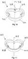
- Figure 1illustrates a heart valve assembly 10 that generally includes a base member 12 and a valve member or "crown" 14.
- the base member 12 and/or crown 14may include one or more connectors for attaching the crown 14 to the base 12 and/or one or more guides for facilitating aligning and/or connecting the crown 14 with the base 12.
- the base member 12may be a generally annular shaped body lying in a plane 16, thereby defining a longitudinal axis 17 substantially orthogonal to the plane 16.
- the base member 12may have a noncircular shape within the plane, such as a multi-lobular shape.
- the base member 12has a tri-lobular shape, i.e., including three lobes 30 separated by three cusps 28, corresponding generally to a cross-section of a biological annulus within which the base member 12 may be implanted, as explained further below.
- the base member 12may define other noncircular shapes within the plane 16, e.g., that may correspond to anatomy of a patient within which the heart valve assembly 10 may be implanted.
- the base member 12may include a substantially rigid anchoring ring or base 18 and a flexible cuff or sewing ring 20 that may extend around a periphery of the anchoring ring 18.
- the cuff 20may simply be a layer of fabric or other material covering at least a portion of the anchoring ring 18.
- the cuff 20may include a section of material (not shown) extending radially from the anchoring ring 18.
- the anchoring ring 18 and cuff 20may be integrally formed as a single element or may be separate components attached to one another.
- the cuff 20may be slidably or fixedly attached to the anchoring ring 18.
- the crown 14may be a generally annular shaped body having a noncircular, e.g., multi-lobular shape, complementary to the base member 12.
- the crown 14has a tri-lobular shape, similar to the base member 12, including three lobes 40 separated by cusps 38.
- the crown 14is a valve member including an annular frame 22, and a plurality of leaflets (not shown for clarity) extending from the frame 22, e.g., attached to commissures 23.
- the frame 22may include a plurality of struts (also not shown for clarity) that may be attached to and/or interact with the leaflets, similar to the struts disclosed in U.S. Patent No. 6,371,983 .
- the crown 14may be a connecting device, such as the connection adapter elements shown in U.S. Patent Application Serial No. 10/646,639, filed 22 August 2003 .
- Components of the heart valve assembly 10, e.g., the base 18 and/or sewing ring 20 of the base member 12 and/or crown 14,may be made from one or more materials, such as one or more alloys, such as alloys of stainless steel, nickel titanium ("Nitinol"), cobalt-chrome (e.g., ELGILOY® from Elgin Specialty Metals, Elgin, IL; CONICHROME® from Carpenter Metals Corp., Wyomissing, PA), molybdenum (e.g., molybdenum TZM alloy, as disclosed, for example, in International Pub. No.
- alloyssuch as alloys of stainless steel, nickel titanium (“Nitinol"), cobalt-chrome (e.g., ELGILOY® from Elgin Specialty Metals, Elgin, IL; CONICHROME® from Carpenter Metals Corp., Wyomissing, PA), molybdenum (e.g., molybdenum TZM alloy,
- WO 03/082363 A2published 9 October 2003
- tungsten-rheniume.g., as disclosed in International Pub. No. WO 03/082363
- the componentsmay be made from polymers, such as polyester (e.g., DACRON® from E. I.
- PTFEpolytetrafluoroethylene
- ePTFEexpanded PTFE
- PEEKpolyether ether ketone
- nylonpolyether-block co-polyamide polymers
- PEBAX®from ATOFINA, Paris, France
- aliphatic polyether polyurethanese.g., TECOFLEX® from Thermedics Polymer Products, Wilmington, MA
- the componentsmay be from or include other materials, such ass extruded collagen, silicone, echogenic, radioactive, radiopaque material or combinations thereof.
- Exemplary radiopaque materials that may be usedinclude barium sulfate, titanium, stainless steel, nickel-titanium alloys, tantalum, and/or gold.
- the cuff 20may include a matrix for cell ingrowth, a fabric, or other flexible material, e.g., a covering (not shown) that may act as a matrix for cell ingrowth, and/or that may be penetrated with a fastener used to attach the cuff 20 to an annulus within which the heart valve assembly 10 is implanted.
- exemplary fabric materialmay include polyester (e.g., DACRON® from E. I. du Pont de Nemours and Company, Wilmington, DE), polypropylene, PTFE, ePTFE, nylon, extruded collagen, silicone, and/or combinations thereof.
- the cuff 20may be an o-ring, or may include a cushioned material, double velour material, and the like, attached using glue or other adhesives and/or fasteners.
- the heart valve assembly 10 and/or any fabric thereinmay also be filled and/or coated with one or more agent delivery matrices known to those skilled in the art, a therapeutic agent, and/or a diagnostic agent.
- agentsmay include radioactive materials; radiopaque materials; cytogenic agents; cytotoxic agents; cytostatic agents; thrombogenic agents, for example, polyurethane, cellulose acetate polymer mixed with bismuth trioxide, and ethylene vinyl alcohol; lubricious, hydrophilic materials; phosphor cholene; anti-inflammatory agents, for example, non-steroidal anti-inflammatories (NSAIDs), such as cyclooxygenase-1 (COX-1) inhibitors (e.g., acetylsalicylic acid, for example ASPIRIN® from Bayer AG, Leverkusen, Germany; ibuprofen, for example ADVIL® from Wyeth, Collegeville, PA; indomethacin; mefenamic acid), COX-2
- the base member 12 and the crown 14may include cooperating detents or other connectors for attaching the crown 14 to the base member 12.
- the base member 12may include protrusions 24, e.g., tabs or prongs, extending from at least one of the anchoring ring 18 and the cuff 20.
- the protrusions 24may be separate from or integral with the cuff 20 and/or anchoring ring 18.
- the protrusions 24extend from the anchoring ring 18 such that they define a sloping proximal surface 24a to accommodate sliding along the crown 14 (not shown) and a blunt distal surface 24b for interlocking with the crown 14 to prevent separation of the crown 14 from the base member 12.
- the protrusions 24may be resilient, e.g., may be biased to extend in a desired direction, e.g., substantially parallel or transverse to the longitudinal axis 17, yet may be resiliently compressed or deflected to facilitate connection of the crown 14 to the base member 12.
- a plurality of protrusions 24may be provided on the anchoring ring 18, e.g., spaced apart from one another about a periphery of the base member 12.
- the base member 12has three sets of protrusions 24, e.g., one set disposed in each lobe 26, offset from one another approximately 120° about the longitudinal axis 17.
- the protrusions 24may be located along an inner surface at the cusps 28 of the base member 12, although alternatively, the protrusions may be provided at the outer apices and/or along inner edges of the lobes 30, such as along the outer edges of the lobes 30, as shown in Figure 21 .
- Figure 3shows an alternative embodiment of a protrusion 24,' namely a flange extending from the anchoring ring 18.
- the protrusion 24'may be biased such that a free end 24b' of the flanges extends diagonally away from the anchoring ring 18', thereby defining a sloped proximal surface 24a.
- the protrusion 24'may be caused to deflect against or into the wall of the anchoring ring 18' but may resiliently return outwardly once released, e.g., such that the free end 24b' is received in an aperture of a crown 14' (not shown, see, e.g., Figure 13 ) to secure the crown 14' to the anchoring ring 18.
- Figure 4illustrates another alternative embodiment of a protrusion 24" that includes a blunt distal surface 24b" and a proximal free end 24a" that may be biased outwardly yet collapsible, similar to the embodiment of Figure 2.
- Figure 5illustrates still another embodiment of a protrusion 24'" with a free end unattached to an anchoring ring 18.'"
- a protrusion 24""may be provided that is solid, and may be filled with a material, such as the radiopaque or other materials described above and/or an agent delivery matrix, therapeutic agent, and/or diagnostic agent, also as described above.
- FIG. 7another embodiment of a connector 124 is shown that may be provided on an anchoring ring 118 (or other component of a base member 112).
- the connector 124includes a plurality of detents 125 (e.g., four shown) spaced apart axially from one another along a direction of the longitudinal axis 117.
- an anchoring ring 218us shown that has a shape that tapers axially relative to longitudinal axis 217.
- the anchoring ring 218includes an inner surface that defines an angle 219 with respect to the longitudinal axis 217.
- a protrusion 224extends from the inner surface of the anchoring ring 218 that includes a sloped proximal surface 224a and a blunt distal surface 224b, similar to previous embodiments.
- the protrusion 224may extend from the outer surface or other location (not shown) of the anchoring ring 218.
- Figure 9illustrates another alternative embodiment of an anchoring ring 218" that includes a plurality of protrusions 224" (e.g., sixteen shown) that are spaced apart from one another along a direction defining an angle 219" with the longitudinal axis 217" to provide a ratcheting connector.
- a plurality of protrusions 224"e.g., sixteen shown
- FIG. 10another embodiment of a base member 312 is shown that includes a plurality of protrusions 324 on legs 313 extending from the base member 312 in a direction substantially parallel to a longitudinal axis 317.
- the legs 313may be integrally formed with the base member 312 or may be attached to the base member 312, and may extend proximally or distally (not shown) from the base member 312.
- FIG. 11another embodiment of a base member 412 is shown that includes connectors, i.e., tabs or protrusions 424e located on an outer surface of the base member 412, i.e., from the anchoring ring 418 or the cuff 420 thereof.
- the cuff 420is shaped and/or is attached to the anchoring ring 418 to ensure that the protrusions 424 are exposed to be engaged with mating connectors on a crown (not shown) attached to the base member 412.
- the anchoring ring 18may include one or more base attachment windows 32, e.g., formed in the lobes 30.
- the windows 32may extend radially through the anchoring rings 18 to accommodate fasteners (not shown) being inserted therethrough.
- a clip or suture(not shown) may be inserted into the window 32 from the inside, through the cuff 20 and into surrounding tissue to attach the base member 12 to the tissue, as explained more particularly below.
- Exemplary fasteners and methods for implanting heart valves or devices using fastenersare disclosed in U.S application Serial No. 10/681,700, filed October 8, 2003 , and entitled "Attachment Device and Methods of Using the Same.
- the crown 14may include one or more crown attachment windows 36, which may be openings or recesses in the wall or frame of the crown 14, preferably extending completely through the wall of the crown 14.
- the crown attachment windows 36may be provided in the lobes 40 such that they are aligned with the base attachment windows 32 in the base member 12 when the crown 14 is attached to the base member 12.
- the crown 14may include one or more cooperating connectors that may interact with the connectors on the base member 12 to secure the crown 14 to the base member 12.
- a plurality of apertures 34e.g., holes, slots, pockets, cavities, and the like, may be provided in the crown 14 for receiving the protrusions 24 therein.
- the material adjacent the apertures 34may be sufficiently flexible and/or resilient to yield and allow the protrusions 24 to be received therein.
- the apertures 34may have a variety of shapes corresponding to the shapes of the protrusions 24, e.g., square, rectangular, circular, or oval shape.
- protrusionsmay be provided on the crown 14 instead of or in addition to the apertures 34, each including a sloping distal surface and a blunt proximal surface.
- the sloping edge of a protrusion on the crown 14may slide along the sloping edge of a corresponding protrusion on the base member 12 until the blunt edges interlock to secure the crown 14 relative to the base member 12.
- at least one of the base member 12 and the crown 14may include a track or channel adjacent the protrusions for guiding the protrusions on the crown 14 into alignment with the protrusions on the base member 12.
- crownsthat include apertures that may be used to received connectors from base members, such as those shown in Figures 3-9 .
- a covering(not shown) may be attached to or otherwise surround the crowns, as long as the apertures are exposed to receive the mating connectors from the base members.
- Figure 13illustrates an embodiment of a crown 14' that includes a tapered section 15' angled relative to the longitudinal axis 17' and an aperture 34.
- the base member 12'(not shown) may include a complementary taper such that crown 14' may fit into or over, and, consequently, mate with the base member 12.
- FIG 14another embodiment of a crown 114 is shown that includes a connector including a plurality of apertures 134 (four shown) spaced apart axially from one another along a direction of a longitudinal axis 117. Apertures 134 may be provided at the distal and/or proximal (not shown) ends of the crown 114 such that the apertures 134 may receive corresponding protrusions 125 from the base member 112 (not shown, see Figure 7 ).
- Figure 15shows another alternative embodiment of a crown 114' that includes multiple apertures 134," each having an adjacent wall section that is angled relative to the longitudinal axis 217.' These angled or ramped wall sections may facilitate protrusions on a base member (not shown) being received therein when the crown 114' is being connected to the base member.
- Figure 16shows yet another embodiment of a crown 214 having a tapered shape defining an angle 221 that is complementary to the base member 212 shown in Figure 8 .
- the crown 214includes an aperture 234 in the inner surface, although the aperture 234 may be provided at other locations corresponding to the protrusion 224 on the base member 212.
- crowns 214,' 214"have a tapered shape, and include a plurality of detents 234,' 234" (fifteen shown) for interlocking with cooperating detents 424" on base member 212" (shown in Figures 9 and 19 ).
- apertures 234'extend completely through a wall of the crown 214.
- the crown 214"may include apertures 234" that do not extend completely through a wall of the crown 214," thereby defining pockets.
- the crown 214" and the base member 212"include complementary tapered shapes, e.g., tapering from a larger distal dimension to a smaller proximal dimension.
- the detents 234"are on the inner surface of the crown 214" and the detents 224" are on the outer surface of the base member 212.”
- the crown and base membermay be tapered smaller from their proximal to distal ends (not shown).
- the detentsmay be provided on an outer surface of the crown and on an inner surface of the base member to allow the detents to ratchet together.
- the crown 214" and base member 212" shown in Figure 19are not to scale.
- the slope of the taperis such that the length of the crown 214" and base member 212" is longer than the change in their cross-sections, thereby maximizing the opening through the crown 214" and base member 212," e.g., to maximize hemodynamic flow through the resulting heart valve assembly 210.”
- a crownsuch as the crown 14 shown in Figures 1 and 22
- the lobes 40 of the crown 14may be aligned with the lobes 30 of the base member 12.
- the protrusions 24 and apertures 34may be aligned with one another such that the protrusions 24 may be received in corresponding apertures 34 to attach the crown 14 to the base member 12.
- protrusions 24 provided on the base member 12 and corresponding apertures 34are provided on the crown 14, it will be appreciated that the protrusions and apertures may be interchanged on the base member 12 and crown 14 (not shown). As long as each protrusion on one of the base member and crown can be aligned with a corresponding aperture or protrusion on the other of the crown and the base member, cooperating connectors may be used to attach the crown to the base member.
- the base member 12 and/or crown 14may include one or more guide markers for facilitating aligning the crown 14 with the base member 12.
- the base member 12 and crown 14may include a set of one or more guide markers 42, 44 that may be raised, textured, colored, radiopaque, and/or echogenic markers on a surface of the base member 122 and/or crown 14.
- the guide markersmay provide a visual indication (e.g., directly and/or using an imaging apparatus), an auditory indication, and/or a tactile indication of the relative orientation and/or location of the crown 14 with the base member 12, e.g., about the longitudinal axis 17.
- visual guide markers 42, 44may be provided on the crown 14 and the base member 12, e.g., at one or more of the cusps 38, 28.
- the markers 42are provided on an outer surface of the crown 14 and on a proximal surface of the base member 122.
- guide markersmay be provided on the lobes 40, 30, and/or on inner surfaces, proximal surfaces, and/or distal surfaces of the crown 14 and/or the base member 12.
- the visual markers 42 on the crown 14may align with the markers 44 on the base member 12 when the crown 14 is aligned with the base member 12.
- a user observing the crown14 being directed towards the base member 12, e.g., from above,may be informed that the crown 14 is properly oriented and/or may be properly connected to the base member 12 based upon the visual markers 42, 44.
- the visual markers 42, 44may include symbols, e.g., triangles, circles, rectangles, and the like (not shown), that may be easily identified, e.g., to inform a surgeon of the location on the crown 14 and/or base member 12 associated with a particular symbol.
- tactile markerssuch as tab markers 46 may be provided on the base member 12 and/or, optionally, on the crown 14. As shown in Figure 1 , the tab markers 46 are raised portions extending from the upper or proximal surface of the anchoring ring 18 at the cusps 28. To form the tab markers 46, a height of the anchoring ring 18 (parallel to the longitudinal axis 17) may be varied, e.g., making the height smaller at the lobes 30 and larger at the cusps 28 thin such that portions of the anchoring ring 18 at the cusps 28 extend proximally, thereby defining the tab markers 46. Stated differently, the proximal surface of the anchoring ring 18 may have a scalloped shape, e.g., where the height of the anchoring ring 18 peaks at the cusps 28 and defines valleys at the lobes 30.
- the distal surface of the crown 14may have a complementary shape.
- the cusps 38 of the crown 14may have a smaller height than the lobes 40 such that the tab markers 46 may be received in recesses (not shown) in the crown 14.
- the complementary shapes of the base member 12 and crown 14may only permit the crown 14 to be mated with the base member 12 when the complementary shapes, e.g., the tab markers 46 and recesses, fit together.
- the usermay receive a tactile indication when the crown 14 is be aligned with the base member 12 in order to ensure that the multi-lobular shapes of the crown 14 and base member 12 are aligned before connecting them together.
- the guidesmay include one or more elongate guide members 50, e.g., including depth markers 52 and/or unidirectional or bidirectional retention elements, e.g., ratcheting elements 54. As explained further elsewhere herein, these guide members may also provided connectors for attaching the crown 14 to the base member 12.
- the guide members 50may be threads, filaments, wires, or other tethers that extend from the base member 12.
- the tethers 50may be attached to, pre-threaded through, or otherwise placed on the base memberl2, e.g., at spaced apart intervals, preferably at the ends of the lobes 30 such that tethers 50 may be aligned with the commissures 23 on the crown 14.
- the tethers 50may be attached to the base member 12 during manufacturing or before or during implantation of the heart valve assembly 10.
- the tethers 50may be formed from a variety of materials, similar to other components of the heart valve assembly 10, as described elsewhere herein, e.g., a fine gauge wire or suture material.
- the tethers 50may be stiff or flexible, and/or may be resiliently bendable or plastically pliable.
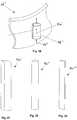
- the tethers 50may have a variety of cross-sections.
- Figure 27shows a guide member 50' having a square or rectangular cross-sectional shape
- Figure 28shows a guide member 50" having a circular or oval cross-sectional shape
- Figure 29shows a guide member 50"' having a semicircular or semi-oval cross-sectional shape.
- a guide tube(not shown) may be provided through which each tether 50 may be inserted.
- the guide tubemay be a substantially rigid, semi-rigid, or flexible tubular body, e.g., a hypotube or polyamide tube.
- Such guide tubesmay enhance the column strength of the tethers during their use to guide a crown towards a base member.
- the guide tubesmay be slidable relative to the tethers such that guide tubes may be removed proximally from around the tethers during a procedure, as explained further below.
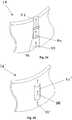
- the crown 14may include one or more ports or guide channels through which guide member, such as the tethers 50 shown in Figure 1 , may be introduced.
- a guide channel 56is shown that may be formed in a wall of the crown 14.
- a recess 57may be provided in the crown 14, e.g., in an outer surface (shown) or an inner surface (not shown) thereof, that extends axially along the crown 14.
- a cover 58may extend across at least a portion of the recession 57, thereby defining the guide channel 56 thereunder.
- a guide membersuch as tether 50 described above (not shown), may be inserted through the guide channel 56, e.g., in the direction shown by arrows 59.
- the guide channel 56may have a variety of cross-sections, e.g., a rectangular cross-section, as shown, or alternatively, a square, semicircular or other at least partial elliptical shape (not shown), depending upon the shape of the tether 50. If a guide tube is provided around the tether, the guide channel 56 may have a size large enough to slidably receive the guide tube therethrough.
- a guide channel 56'may be formed by and/or in a wall of the crown 14.
- transverse slots 57'may be created in the wall of the crown 14' at two locations axially disposed from one another, thereby creating a guide channel 56' under the wall 58' through the openings 57.
- a separate piece of materialmay be attached to the wall of the crown 14' to create the guide channel 56.
- a guide channel 56"extending from a crown 14.
- the guide channel 56"may be a tubular section of material 58" attached to the wall of the crown 14," e.g., by an adhesive, sutures, and the like.
- the guide channel 56"may have a cylindrical shape, as shown, or other shapes (not shown).
- the guide channelsmay include a guide tube therein, e.g., similar to the guide tubes described above for reinforcing the tethers 50.
- the crown 14when tethers 50 (or other guide members, not shown) are inserted through guide channels (not shown) at corresponding locations in the crown 14, the crown 14 may be slidable along the tethers 50. Thus, the crown 14 may be lowered towards the base member 12 along the tethers 50.
- the tethers 50 and corresponding guide channelsare attached at the ends of the lobes 30, 40 of the base member 12 and crown 14.
- the tethers 50may be tightened or deployed to attach the crown 14 to the base member 12.
- the tethersmay be used in conjunction with other connectors described herein, e.g., to form a redundant connection, or may be used alone to form both the connection between the crown 14 and the base member 12, while also acting as a guide to orient the devices.
- the tethers 50may include ratcheting elements 54, e.g., pawls or other detents, that may interact with the crown 14 and/or the guide channels.
- the ratcheting elements 54may provide a tactile indicator of the distance from the crown 14 to the base member 12 and/or may prevent the crown 14 from being removed once it is directed towards the base member 12.
- the ratcheting elements 54may include sloping proximal surfaces and blunt distal surfaces, allowing the crown 14 to be directed down the tethers 50, but preventing them from being directed back up.
- the ratcheting elements 54may including sloping proximal and distal surfaces, allowing the crown 14 to be directed down or up the tethers 50, but provided a resistance to movement.
- the ratcheting elements 54may include one or more sets of detents spaced apart at different distances along the tethers 50.
- a first set of detents(not shown) may be provided at a predetermined distance from the base member 12, e.g., several centimeters.
- a second set of detents(also not shown) may then be provided to indicate that the crown 14 has been lowered into its final position seated against the base member 12.
- additional intermediate sets of detentsmay be provided spaced apart between the first and second sets, thereby providing a depth gauge that may inform the user how far the crown 14 has been lowered or has left to be lowered.
- the detentsmay vary in size along the length of the tethers.
- larger detentsmay be provided at predetermined intervals (not shown), provided greater auditory and/or tactile feedback to the user.
- the detentsmay decrease in size from the ends of the tethers 50 towards the base member 12, may increase in size towards the base member 12, or may vary in some other desired manner, depending upon the feedback intended to be provided to the user.
- the components of the heart valve assemblies described hereinmay be manufactured using methods well known to those skilled in the art.
- manufacturing techniquesinclude molding, machining, casting, forming (e.g., pressure forming), crimping, stamping, melting, screwing, gluing, welding, die cutting, laser cutting, electrical discharge machining (EDM), etching or combinations thereof.
- Heart valve assemblies disclosed in U.S. Patent Nos. 6,241,765 , 6,371,983 , and 5,976,183may be modified such that they may incorporated into a crown or may be attached to a valve connector adaptor, such as those described herein.
- Other heart valves that may be incorporated into a heart valve assembly, as described herein,may include, for example, the Advantage Bileaflet heart valve, Parallel valve, Freestyle stentless aortic valve, Hancock Porcine heart valve, Hancock apical left ventricular connector model 174A, Hancock valved conduit models 100, 105, 150, Hall Medtronic heart valve, Hall Medtronic valved conduit, MOSAIC® heart valve, Intact porcine tissue valve (by Medtronic, Inc.
- JUDE MEDICAL® mechanical heart valvesST. JUDE MEDICAL® mechanical heart valve Hemodynamic Plus (HP) series
- SJM REGENT® valveHemodynamic Plus (HP) series
- TORONTO SPV®St. Porcine Valve
- SJM BIOCOR® valveSJM EPIC® valve
- SJM EPIC® valveSt. Jude Medical, Inc., St. Paul, MN
- Sorin BicarbonSorin Carbocast, Sorin Carboseal Conduit, Sorin Pericarbon and Sorin Pericarbon Stentless (by Snia S.p.A., Italy).
- any elements, sub-assemblies, or the entire heart valve assemblies described hereinmay be coated, e.g., by dip-coating or spray-coating methods known to one having ordinary skill in the art, utilizing materials such as PTFE (e.g., TEFLON® from E. I. du Pont de Nemours and Company, Wilmington, DE), polyester (e.g., DACRON® from E. I. du Pont de Nemours and Company, Wilmington, DE), gelatin, gel, other polymers or combinations thereof.
- PTFEe.g., TEFLON® from E. I. du Pont de Nemours and Company, Wilmington, DE
- polyestere.g., DACRON® from E. I. du Pont de Nemours and Company, Wilmington, DE
- gelatingel
- Other polymers or combinations thereofe.g., polymers or combinations thereof.
- Time release coating methods known to one having ordinary skill in the artmay also be used to delay the release of an agent in the coating.
- the heart valve assemblies or any elements thereofmay be covered with a fabric, for example, polyester (e.g., DACRON® from E. I. du Pont de Nemours and Company, Wilmington, DE), polypropylene, PTFE (e.g., TEFLON® from E. I. du Pont de Nemours and Company, Wilmington, DE), ePTFE, nylon, extruded collagen, gel, gelatin, silicone, or combinations thereof.
- a fabricfor example, polyester (e.g., DACRON® from E. I. du Pont de Nemours and Company, Wilmington, DE), polypropylene, PTFE (e.g., TEFLON® from E. I. du Pont de Nemours and Company, Wilmington, DE), ePTFE, nylon, extruded collagen, gel, gelatin, silicone, or combinations thereof.
- Methods of covering an implantable device with fabricare known to those having ordinary skill in the art, for example, sintering, spray coating, adhesion, loose covering, dipping
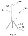
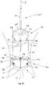
- the holder 60may include an elongate shaft 62 including a handle 64 on a proximal end 66 and a plurality of arms 68 on a distal end 70 thereof.
- the shaft 62may be a substantially rigid and/or malleable body that may be fixed or rotatable relative to the arms 68.
- Free ends 72 of the arms 68may include connectors 74 that may be configured for releasably holding a base member and/or crown (not shown), such as those described above.
- three arms 68are shown, it will be appreciated that more or fewer arms may be provided (not shown), if desired.
- the connectors 74may be remotely triggered, e.g., from an actuator (not shown) on the handle 64, to attach and/or release a base and/or crown.
- Figure 33shows the holder 60 carrying a crown 12 using the connectors 74 on arms 68.
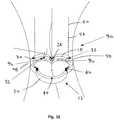
- a methodfor implanting a heart valve assembly within a biological annulus 90, which may be the site for replacement of an existing natural or previously implanted heart valve, such as a tricuspid, mitral, aortic, or pulmonary valve within a patient's heart (not shown).
- the annulus 90may have multiple, for example two or three natural lobes 92 (three lobes being shown in Figure 31 with one lobe cut-away).
- the method described belowrefers generally the heart valve assembly 10 shown in Figure 1 , it will be appreciated that any of the components described herein may be implanted using similar procedures.
- the patientBefore implanting the heart valve assembly 10, the patient may be prepared for the procedure using known methods. For example, the patient may be placed on cardiopulmonary bypass (CPB), and the patient's heart may be exposed, e.g., by sternotomy, thoracotomy, or other open or minimally invasive procedure. An incision may be created in the blood vessel above the valve being replaced (not shown), e.g., the aorta for an aortic valve replacement, in order to access the annulus 90. The existing natural or prosthetic heart valve (also not shown) may be removed from the annulus 90 using known methods.
- CPBcardiopulmonary bypass
- a base member 12may be selected based upon the anatomy encountered, e.g., having a plurality of lobes 30 matching the lobes 92 of the annulus 90 and/or having a cross-sectional dimension corresponding to the interior cross-section of the annulus 90.
- the base member 12may be introduced into the annulus 90, as shown by arrows 94.
- the base member 10may be carried into the annulus 90 using the holder 60 (not shown) or other tool. If necessary, based upon the anatomy encountered, the shaft 62 of the holder 60 may be bent or otherwise deformed to facilitate accurately placing the base member 12 within the annulus 90.
- the base member 12may oriented before or while being introduced into the annulus 90 such that the lobes 30 of the base member 12 are aligned with the natural lobes 92 of the annulus 90. Once properly oriented, the base member 12 be secured within the annulus 90, whereupon the base member 12 may be released from the holder 60, which may then be removed from the annulus 90.
- the base member 12is implanted directly within the annulus 90.
- one or more fasteners 96e.g., clips or sutures (not shown) may be directed through the base attachment windows 32 into tissue 98 surrounding the annulus 90.
- a plurality of fastenersmay be driven through a flexible cuff 20 surrounding an anchoring ring 18 having the windows 32 therein, e.g., spaced apart from one another about the periphery of the base member 12.
- Exemplary fasteners and methods for using them to implant the base member 12may be found in U.S. Patent Application Serial Nos. 10/327,821, filed 20 December 2002 , 10/646,639, filed 22 August 2003 , and 10/681,700, filed 8 October 2003 .
- the base member 12may be implanted above the biological annulus 90, e.g., within the enlarged space above a natural valve annulus. This configuration may allow a larger heart valve assembly 10 to be implanted, thereby maximizing the open area through which blood may flow through the implantation site.
- the base member 12may include a flexible sewing ring (not shown) that may be placed against the tissue above the annulus 90, whereupon one or more fasteners may be driven through the sewing ring into the tissue to secure the base member 12.
- the tethers 50 or other guide membersmay be attached to the base member 12 when the base member 12 is introduced into the annulus 90.
- the tethers 50may be attached to the base member 12 during manufacturing or in preparation for performing the valve implantation procedure.
- the tethers 50may be attached to the base member 12 after being deployed in the annulus 90, e.g., by threading the tethers 50 through openings in the base member 12.
- the tethers 50extend from the outer ends of the lobes 30 of the base member 12, although alternatively, the tethers 50 may extend from the cusps 28 or other locations (not shown).
- the tethers 50may extend through a
- the crown 14may be introduced into the annulus 90, e.g., using the holder 60.
- the leaflets(not shown) may be attached to the crown 14 before the crown 14 is introduced.
- the base member 12includes tethers 50 or other guide members
- the tethers 50may be fed through guide channels (not shown) in the crown 14.
- the tubular guidesmay be fed through the guide channels, which may include their own tubular guides. Once the tethers 50 are inserted through the guide channels, the tubular guides may be removed or may remain to facilitate manipulation of the tethers 50.
- the tethers 50may facilitate aligning the crown 14 with the base member 12, e.g., radially about longitudinal axis 17.
- the ratcheting elements 54 on the tethers 50may provide audible and/or tactile feedback to the user as the crown 14 is advanced down the tethers 50 towards the base member 12.
- visual markers on the crown 14 and/or base member 12, e.g., markers 42, 44may be monitored directly or via imaging (e.g., x-ray, magnetic resonance imaging (MRI), ultrasound, computed tomography (CT), echocardiogram, and the like), providing feedback regarding the proximity and orientation of the crown 14 relative to the base member 12.
- the protrusion guide markers 46may provide tactile feedback of the proximity and orientation of the crown 14.
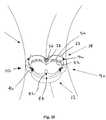
- the crown 14may be deployed and attached to the base member 12. As shown, as the crown 14 is placed adjacent the base member 12, the crown 14 may at least partially enter the base member 12. Alternatively, the crown 14 may at least partially surround the base member 12 or merely abut the base member 12 (not shown). As the crown 14 is seated against the base member 12, cooperating connectors 34, 24 on the crown 14 and base member 12 may engage one another to substantially secure the crown 14 to the base member 12. For example, as described above, protrusions 24 on the base member 12 may engage within apertures 34 in the crown 14. The connectors 34, 24 may removably or substantially permanently attach the crown 14 to the base member 12. As the protrusions 24 enter into the apertures 34, they may provide audible and/or tactile feedback to the user regarding the proper placement and attachment of the crown 14 and the base member 12.
- the tethers 50may include ratcheting elements (not shown) that engage when the crown 14 is seated against the base member 12. For example, these ratcheting elements may interlock with the guide channels of the crown 14, thereby preventing the crown 14 from being removed from the base member 12. The tethers 50 may then be cut or otherwise disconnected above the crown 14, thereby providing connectors securing the crown 14 to the base member 12.
- the tethers 50may be knotted to further secure the crown 14 and/or may be welded or fused, e.g., using radio frequency (RF) energy, an adhesive, and the like.
- RFradio frequency
- the tethers 50may be removed after the cooperating connectors 42, 44 engage, e.g., by releasing one end of a looped thread defining each tether, and pulling the thread completely out of the base member 12 and crown 14.
- FIG. 35illustrates the heart valve assembly 10 once the crown 14 and base member 12 are properly deployed in the annulus 90.
- leafletsmay be attached to the crown 14 and/or the base member 12, for example, as taught by Lane in U.S. Patent No. 6,371,983 .
- a separate valve membermay be introduced into the annulus 90 and attached to the crown and/or base member, similar to the embodiments described above.
- the crown, the base member, and/or the valve membermay include guides an d/or cooperating connectors for orienting the valve member and/or attaching it to the crown and/or base member, as will be appreciated by those skilled in the art.
- the crown 14may be detached and/or removed (not shown) from the base member 12.
- a tool(not shown) may be introduced into the annulus 90 to depress the protrusions 24 or disengage them (or any other cooperating connectors, not shown) from the apertures 34 to release the crown 14.
- the crown 14may then be retrieved, e.g., using the holder 60 or other tool, and withdrawn from the annulus 90.
- the crown 14 and/or its leaflets or valve bodymay be replaced, as needed.
- the base member 12may also be removed by removing the fasteners securing the base member 12 to the annulus 90, as will be appreciated by those skilled in the art.
Landscapes
- Health & Medical Sciences (AREA)
- Engineering & Computer Science (AREA)
- Biomedical Technology (AREA)
- Cardiology (AREA)
- Oral & Maxillofacial Surgery (AREA)
- Transplantation (AREA)
- Heart & Thoracic Surgery (AREA)
- Vascular Medicine (AREA)
- Life Sciences & Earth Sciences (AREA)
- Animal Behavior & Ethology (AREA)
- General Health & Medical Sciences (AREA)
- Public Health (AREA)
- Veterinary Medicine (AREA)
- Prostheses (AREA)
Description
- The present invention relates generally to heart valves that may be implanted into a patient, and, more particularly, to multiple component heart valve assemblies that may be assembled together.
- Prosthetic heart valves can replace defective human valves in patients. Prosthetic valves commonly include sewing rings, suture cuffs, or rings that are attached to and extend around the outer circumference of the prosthetic valve orifice. Because of their circular cross-sections, sewing rings that are implanted may not optimally fit the biological annulus into which a valve may be implanted. As a result, natural blood hemodynamics through and around the valve may be impaired, resulting in clotting, possible emboli production, and eventual calcification of the valve structure.
- As patients grow, particularly pediatric patients, the leaflets of a valve may no longer be properly sized to fit the annulus. Leaflets may also calcify or otherwise foul and need to be replaced. To replace the leaflets on a single-piece prosthetic valve, the entire valve must be removed, which may cause trauma to the annulus and jeopardize implantation of a replacement valve. Further, it may be difficult to work around and through leaflets of a valve to attach a leaflet-laden valve, possibly damaging the leaflets and extending the length of the valve replacement procedure.
- Sewing rings can also be tedious and time consuming to secure to a valve orifice. To assemble multiple component heart valves, one component has to be sewn into another in vivo, resulting in a complex and time consuming process. The complexity of the procedure also provides a greater opportunity for mistakes and requires a patient to be on cardiopulmonary bypass for a lengthy period.
- Multiple piece heart valves also typically require a significant amount of handling during implantation, potentially exposing the delicate leaflets to damage before or during in vivo implantation. Additionally, orientation of the components of a multiple piece heart valve is generally not defined by the device, making the implantation of the second piece of the valve less intuitive. The surgeon must align the components of the valve during in vivo assembly when limited access can impair dexterity and the fragile valve components are at risk of being damaged. Also, known multiple piece valves lack sufficient mechanical safeguards to insure that the surgeon will properly orient or secure the valve components. Once implanted, multiple component heart valves can have problems with the components fitting each other in a secure and stable manner. Improper fit can cause mechanical stress and hemodynamic anomalies leading to clotting, dislodgement or valve failure.
US 2004/0015232 describes suturing rings for implantable heart valve prostheses. - Accordingly, heart valves, particularly multiple piece valves that may be reliably implanted into biological heart annuluses, e.g., to maximize hemodynamic flow and/or ease implantation, would be useful.
- The present invention is directed to heart valves that may be implanted into a patient, and, more particularly, to multiple component heart valve assemblies that may be assembled together.
- In accordance with one aspect of the present invention, a heart valve assembly is provided that includes a base member including a multi-lobular annular shape within a plane, an annular body including a multi-lobular shape complementary to the multi-lobular shape of the base member, and cooperating connectors on the base member and the annular body for connecting the annular body to the base member. In one embodiment, the connectors may include mating detents on the base member and annular body, e.g., one or more protrusions and one or more apertures for receiving corresponding protrusions therein.
- In an exemplary embodiment, the base member may include an anchoring ring or other rigid base including one or more connectors thereon, and a flexible cuff for attaching the base to a biological annulus. The flexible cuff may include a sewing ring extending radially from the base and/or fabric or other material attached to and/or covering at least a portion of the base. In one embodiment, the base may include one or more windows for accommodating a fastener, e.g., a clip or suture, for attaching the base to the annulus.
- In addition or alternatively, the annular body may include a frame carrying one or more leaflets to provide a valve member. Alternatively, the annular body may be a connecting member for connecting a valve member to the base member.
- In accordance with another aspect of the present invention, a heart valve assembly is provided that includes a base member generally defining a plane and a longitudinal axis substantially orthogonal to the plane, the base member including a multi-lobular annular shape within the plane, an annular body including a multi-lobular shape complementary to the multi-lobular shape of the base member, and guides on at least one of the base member and the annular body for aligning the multi-lobular shapes with one another about the longitudinal axis.
- Optionally, cooperating connectors may be provided on the base member and the annular body for attaching the annular body to the base member. For example, the connectors may include mating detents on the base member and the annular body, e.g., one or more protrusions and one or more apertures for receiving corresponding protrusions therein.
- In one embodiment, the guides may include visual markers on at least one of the base member and the annular body that may aligned within one another when the multi-lobular shape of the annular body is aligned with the multi-lobular shape of the base member. In addition or alternatively, the guides may include tactile or audio markers that provide an indication to a user that the annular body is aligned with the base member. In another embodiment, the guides may include one or more tethers extending from the base member through the annular body such that the annular body is slidable along the tethers to align the annular body with the base member as the annular body is directed towards the base member. Optionally, the tethers may include ratchet elements spaced apart along a portion of the tethers, thereby provided a tactile indication as the annular body is directed towards the base member, e.g., to identify a distance from the annular body to the base member. Preferably, each tether extends through a port or other guide channel in the annular body, and the ratchet elements may engage the guide channel to allow the annular body to be directed towards the base element but preventing the annular body from being directed away from the base member.
- In accordance with another aspect, a method is provided for assembling a heart valve including a base member including a multi-lobular annular shape and a second device including a multi-lobular shape complementary to the multi-lobular shape of the base member. The second device may be moved adjacent to the base member, wherein the multi-lobular shape of the second device aligns with the multi-lobular shape of the base member, and the second device may then be attached to the base member. For example, the second device may be slid along one or more guide members towards the base member. In addition or alternatively, guides on the annular body and/or base member may include visual, auditory, and/or tactile markers that may be monitored to ensure that the annular body is aligned with the base member.
- Once the second device contacts or is otherwise adjacent the base member, cooperating connectors on the second device and the base member may engage to secure the second device to the base member. In one embodiment, the second device may be a valve member, e.g., a single-piece heart valve. Alternatively, the second device may be a frame or other annular body to which a valve may be attached either before or after attaching the frame to the base member. In this alternative, guides may be provided to align and facilitate successive attachment of each component to one another.
- In accordance with still another aspect, a method is provided for implanting a heart valve within a biological annulus within a heart of a patient. Initially, a base member may be attached to the biological annulus, the base member having a multi-lobular annular shape corresponding generally to a cross-section of the annulus. A valve member including a multi-lobular shape complementary to the base member may be directed adjacent the annulus. The valve member may be oriented such that the multi-lobular shape of the valve member is aligned with the multi-lobular shape of the base member, and the valve member may be attached to the base member.
- Other objects and features of the present invention will become apparent from consideration of the following description taken in conjunction with the accompanying drawings.
- The drawings illustrate exemplary embodiments of the invention, in which:
Figure 1 is an exploded perspective view of an embodiment of a heart valve assembly, including a base and a crown.Figures 2-9 are cross-sectional views of various embodiments of the base ofFigure 1 , taken along section A-A, showing connectors thereon.Figures 10 and 11 are perspective views of alternate embodiments of a base that may be incorporated into a heart valve assembly.Figures 12-18 are cross-sectional views of various embodiments of the crown ofFigure 1 , taken along section B-B, showing connectors thereon.Figure 19 is a cross-section of another embodiment of a heart valve, including a plurality of connectors on a base and crown that may ratchet together.Figure 20 is a cross-sectional view of the base ofFigure 1 , taken along section E-E.Figure 21 is a cross-sectional view of an alternative embodiment of a base that may be incorporated into a heart valve assembly.Figure 22 is a cross-sectional view of the crown ofFigure 1 , taken along section F-F.Figure 23 is a cross-sectional view of an alternative embodiment of a crown that may be connected to the base shown inFigure 21 to provide a heart valve assembly.Figures 24-26 are details of various embodiments of a guide channel that may be provided on a crown.Figures 27-29 are perspective views of various embodiments of a guide member.Figure 30 illustrates an embodiment of a valve holder, including connectors for releasably carrying a component of a heart valve assembly during implantation.Figures 31-35 are cross-sectional views of a biological annulus, showing a method for implanting a heart valve assembly.- Turning to the drawings,
Figure 1 illustrates aheart valve assembly 10 that generally includes abase member 12 and a valve member or "crown" 14. As described further below, thebase member 12 and/orcrown 14 may include one or more connectors for attaching thecrown 14 to thebase 12 and/or one or more guides for facilitating aligning and/or connecting thecrown 14 with thebase 12. - The
base member 12 may be a generally annular shaped body lying in aplane 16, thereby defining alongitudinal axis 17 substantially orthogonal to theplane 16. Thebase member 12 may have a noncircular shape within the plane, such as a multi-lobular shape. Preferably, thebase member 12 has a tri-lobular shape, i.e., including threelobes 30 separated by threecusps 28, corresponding generally to a cross-section of a biological annulus within which thebase member 12 may be implanted, as explained further below. It will be appreciated that thebase member 12 may define other noncircular shapes within theplane 16, e.g., that may correspond to anatomy of a patient within which theheart valve assembly 10 may be implanted. - The
base member 12 may include a substantially rigid anchoring ring orbase 18 and a flexible cuff orsewing ring 20 that may extend around a periphery of the anchoringring 18. Thecuff 20 may simply be a layer of fabric or other material covering at least a portion of the anchoringring 18. Alternatively, thecuff 20 may include a section of material (not shown) extending radially from the anchoringring 18. The anchoringring 18 andcuff 20 may be integrally formed as a single element or may be separate components attached to one another. In addition, thecuff 20 may be slidably or fixedly attached to the anchoringring 18. - The
crown 14 may be a generally annular shaped body having a noncircular, e.g., multi-lobular shape, complementary to thebase member 12. Preferably, thecrown 14 has a tri-lobular shape, similar to thebase member 12, including threelobes 40 separated bycusps 38. In a preferred embodiment, thecrown 14 is a valve member including an annular frame 22, and a plurality of leaflets (not shown for clarity) extending from the frame 22, e.g., attached tocommissures 23. The frame 22 may include a plurality of struts (also not shown for clarity) that may be attached to and/or interact with the leaflets, similar to the struts disclosed inU.S. Patent No. 6,371,983 . Alternatively, thecrown 14 may be a connecting device, such as the connection adapter elements shown inU.S. Patent Application Serial No. 10/646,639, filed 22 August 2003 - Components of the
heart valve assembly 10, e.g., thebase 18 and/orsewing ring 20 of thebase member 12 and/orcrown 14, may be made from one or more materials, such as one or more alloys, such as alloys of stainless steel, nickel titanium ("Nitinol"), cobalt-chrome (e.g., ELGILOY® from Elgin Specialty Metals, Elgin, IL; CONICHROME® from Carpenter Metals Corp., Wyomissing, PA), molybdenum (e.g., molybdenum TZM alloy, as disclosed, for example, in International Pub. No.WO 03/082363 A2, published 9 October 2003 WO 03/082363 - Any or all elements of the
heart valve assembly 10, for example, thecuff 20, may include a matrix for cell ingrowth, a fabric, or other flexible material, e.g., a covering (not shown) that may act as a matrix for cell ingrowth, and/or that may be penetrated with a fastener used to attach thecuff 20 to an annulus within which theheart valve assembly 10 is implanted. Exemplary fabric material may include polyester (e.g., DACRON® from E. I. du Pont de Nemours and Company, Wilmington, DE), polypropylene, PTFE, ePTFE, nylon, extruded collagen, silicone, and/or combinations thereof. Optionally, thecuff 20 may be an o-ring, or may include a cushioned material, double velour material, and the like, attached using glue or other adhesives and/or fasteners. - Optionally, the
heart valve assembly 10 and/or any fabric therein may also be filled and/or coated with one or more agent delivery matrices known to those skilled in the art, a therapeutic agent, and/or a diagnostic agent. These agents may include radioactive materials; radiopaque materials; cytogenic agents; cytotoxic agents; cytostatic agents; thrombogenic agents, for example, polyurethane, cellulose acetate polymer mixed with bismuth trioxide, and ethylene vinyl alcohol; lubricious, hydrophilic materials; phosphor cholene; anti-inflammatory agents, for example, non-steroidal anti-inflammatories (NSAIDs), such as cyclooxygenase-1 (COX-1) inhibitors (e.g., acetylsalicylic acid, for example ASPIRIN® from Bayer AG, Leverkusen, Germany; ibuprofen, for example ADVIL® from Wyeth, Collegeville, PA; indomethacin; mefenamic acid), COX-2 inhibitors (e.g., VIOXX® from Merck & Co., Inc., Whitehouse Station, NJ; CELEBREX® from Pharmacia Corp., Peapack, NJ; COX-1 inhibitors); immunosuppressive agents, for example, Sirolimus (RAPAMUNE®, from Wyeth, , Collegeville, PA), or matrix metalloproteinase (MMP) inhibitors (e.g., tetracycline and tetracycline derivatives) that act early within the pathways of an inflammatory response. Examples of other agents that may be used are disclosed inWalton et al, Inhibition of Prostoglandin E2 Synthesis in Abdominal Aortic Aneurysms, Circulation, July 6, 1999, 48-54;Tambiah et al, Provocation of Experimental Aortic Inflammation Mediators and Chlamydia Pneumoniae, Brit. J. Surgery 88 (7), 935-940;Franklin et al, Uptake of Tetracycline by Aortic Aneurysm Wall and Its Effect on Inflammation and Proteolysis, Brit. J. Surgery 86 (6), 771-775;Xu et al, Spl Increases Expression of Cyclooxygenase-2 in Hypoxic Vascular Endothelium, J. Biological Chemistry 275 (32) 24583-24589; andPyo et al, Targeted Gene Disruption of Matrix Metalloproteinase-9 (Gelatinase B) Suppresses Development of Experimental Abdominal Aortic Aneurysms, J. Clinical Investigation 105 (11), 1641-1649. - The
base member 12 and thecrown 14 may include cooperating detents or other connectors for attaching thecrown 14 to thebase member 12. Turning toFigures 2-9 , thebase member 12 may includeprotrusions 24, e.g., tabs or prongs, extending from at least one of the anchoringring 18 and thecuff 20. Theprotrusions 24 may be separate from or integral with thecuff 20 and/or anchoringring 18. In an exemplary embodiment, shown inFigure 2 , theprotrusions 24 extend from the anchoringring 18 such that they define a slopingproximal surface 24a to accommodate sliding along the crown 14 (not shown) and a blunt distal surface 24b for interlocking with thecrown 14 to prevent separation of thecrown 14 from thebase member 12. Theprotrusions 24 may be resilient, e.g., may be biased to extend in a desired direction, e.g., substantially parallel or transverse to thelongitudinal axis 17, yet may be resiliently compressed or deflected to facilitate connection of thecrown 14 to thebase member 12. - For example, as shown in
Figures 1 and20 , a plurality ofprotrusions 24 may be provided on the anchoringring 18, e.g., spaced apart from one another about a periphery of thebase member 12. In a preferred embodiment, thebase member 12 has three sets ofprotrusions 24, e.g., one set disposed in each lobe 26, offset from one another approximately 120° about thelongitudinal axis 17. As shown inFigure 20 , theprotrusions 24 may be located along an inner surface at thecusps 28 of thebase member 12, although alternatively, the protrusions may be provided at the outer apices and/or along inner edges of thelobes 30, such as along the outer edges of thelobes 30, as shown inFigure 21 . Figure 3 shows an alternative embodiment of aprotrusion 24,' namely a flange extending from the anchoringring 18.' The protrusion 24' may be biased such that a free end 24b' of the flanges extends diagonally away from the anchoring ring 18', thereby defining a slopedproximal surface 24a.' The protrusion 24' may be caused to deflect against or into the wall of the anchoring ring 18' but may resiliently return outwardly once released, e.g., such that the free end 24b' is received in an aperture of a crown 14' (not shown, see, e.g.,Figure 13 ) to secure the crown 14' to the anchoringring 18.'Figure 4 illustrates another alternative embodiment of aprotrusion 24" that includes a blunt distal surface 24b" and a proximalfree end 24a" that may be biased outwardly yet collapsible, similar to the embodiment ofFigure 2. Figure 5 illustrates still another embodiment of a protrusion 24'" with a free end unattached to ananchoring ring 18.'" In addition or alternatively, as shown inFigure 6 , aprotrusion 24"" may be provided that is solid, and may be filled with a material, such as the radiopaque or other materials described above and/or an agent delivery matrix, therapeutic agent, and/or diagnostic agent, also as described above.- Turning to
Figure 7 , another embodiment of aconnector 124 is shown that may be provided on an anchoring ring 118 (or other component of a base member 112). Theconnector 124 includes a plurality of detents 125 (e.g., four shown) spaced apart axially from one another along a direction of thelongitudinal axis 117. - Turning to
Figure 8 , another embodiment of ananchoring ring 218 us shown that has a shape that tapers axially relative tolongitudinal axis 217. In the embodiment shown, theanchoring ring 218 includes an inner surface that defines anangle 219 with respect to thelongitudinal axis 217. Aprotrusion 224 extends from the inner surface of theanchoring ring 218 that includes a slopedproximal surface 224a and a blunt distal surface 224b, similar to previous embodiments. Alternatively, theprotrusion 224 may extend from the outer surface or other location (not shown) of theanchoring ring 218. Figure 9 illustrates another alternative embodiment of ananchoring ring 218" that includes a plurality ofprotrusions 224" (e.g., sixteen shown) that are spaced apart from one another along a direction defining anangle 219" with thelongitudinal axis 217" to provide a ratcheting connector.- Turning to
Figure 10 , another embodiment of abase member 312 is shown that includes a plurality ofprotrusions 324 onlegs 313 extending from thebase member 312 in a direction substantially parallel to alongitudinal axis 317. Thelegs 313 may be integrally formed with thebase member 312 or may be attached to thebase member 312, and may extend proximally or distally (not shown) from thebase member 312. - Turning to
Figure 11 , another embodiment of abase member 412 is shown that includes connectors, i.e., tabs or protrusions 424e located on an outer surface of thebase member 412, i.e., from the anchoring ring 418 or thecuff 420 thereof. Preferably, thecuff 420 is shaped and/or is attached to the anchoring ring 418 to ensure that theprotrusions 424 are exposed to be engaged with mating connectors on a crown (not shown) attached to thebase member 412. - Returning to
Figure 1 , optionally, the anchoringring 18 may include one or morebase attachment windows 32, e.g., formed in thelobes 30. Thewindows 32 may extend radially through the anchoring rings 18 to accommodate fasteners (not shown) being inserted therethrough. For example, ifcuff 20 covers thebase attachment windows 32, a clip or suture (not shown) may be inserted into thewindow 32 from the inside, through thecuff 20 and into surrounding tissue to attach thebase member 12 to the tissue, as explained more particularly below. Exemplary fasteners and methods for implanting heart valves or devices using fasteners are disclosed inU.S application Serial No. 10/681,700, filed October 8, 2003 - Similarly, the
crown 14 may include one or morecrown attachment windows 36, which may be openings or recesses in the wall or frame of thecrown 14, preferably extending completely through the wall of thecrown 14. Thecrown attachment windows 36 may be provided in thelobes 40 such that they are aligned with thebase attachment windows 32 in thebase member 12 when thecrown 14 is attached to thebase member 12. - Turning to
Figure 12 , thecrown 14 may include one or more cooperating connectors that may interact with the connectors on thebase member 12 to secure thecrown 14 to thebase member 12. For example, as shown, a plurality ofapertures 34, e.g., holes, slots, pockets, cavities, and the like, may be provided in thecrown 14 for receiving theprotrusions 24 therein. The material adjacent theapertures 34 may be sufficiently flexible and/or resilient to yield and allow theprotrusions 24 to be received therein. Theapertures 34 may have a variety of shapes corresponding to the shapes of theprotrusions 24, e.g., square, rectangular, circular, or oval shape. - Alternatively, protrusions (not shown) may be provided on the
crown 14 instead of or in addition to theapertures 34, each including a sloping distal surface and a blunt proximal surface. The sloping edge of a protrusion on thecrown 14 may slide along the sloping edge of a corresponding protrusion on thebase member 12 until the blunt edges interlock to secure thecrown 14 relative to thebase member 12. Optionally, at least one of thebase member 12 and thecrown 14 may include a track or channel adjacent the protrusions for guiding the protrusions on thecrown 14 into alignment with the protrusions on thebase member 12. - Turning to
Figures 13-18 , alternative embodiments of crowns are shown that include apertures that may be used to received connectors from base members, such as those shown inFigures 3-9 . Optionally, a covering (not shown) may be attached to or otherwise surround the crowns, as long as the apertures are exposed to receive the mating connectors from the base members. Figure 13 illustrates an embodiment of a crown 14' that includes a tapered section 15' angled relative to the longitudinal axis 17' and anaperture 34.' In this embodiment, the base member 12' (not shown) may include a complementary taper such that crown 14' may fit into or over, and, consequently, mate with thebase member 12.'- Turning to
Figure 14 , another embodiment of acrown 114 is shown that includes a connector including a plurality of apertures 134 (four shown) spaced apart axially from one another along a direction of alongitudinal axis 117.Apertures 134 may be provided at the distal and/or proximal (not shown) ends of thecrown 114 such that theapertures 134 may receive correspondingprotrusions 125 from the base member 112 (not shown, seeFigure 7 ). Figure 15 shows another alternative embodiment of a crown 114' that includesmultiple apertures 134," each having an adjacent wall section that is angled relative to thelongitudinal axis 217.' These angled or ramped wall sections may facilitate protrusions on a base member (not shown) being received therein when the crown 114' is being connected to the base member.Figure 16 shows yet another embodiment of acrown 214 having a tapered shape defining anangle 221 that is complementary to thebase member 212 shown inFigure 8 . Thecrown 214 includes anaperture 234 in the inner surface, although theaperture 234 may be provided at other locations corresponding to theprotrusion 224 on thebase member 212.- Turning to
Figures 17-19 , additional embodiments ofcrowns 214,' 214" are shown that have a tapered shape, and include a plurality ofdetents 234,' 234" (fifteen shown) for interlocking with cooperatingdetents 424" onbase member 212" (shown inFigures 9 and19 ). In the embodiment shown inFigure 17 , apertures 234' extend completely through a wall of thecrown 214.' Alternatively, as shown inFigure 18 , thecrown 214" may includeapertures 234" that do not extend completely through a wall of thecrown 214," thereby defining pockets. - As shown in
Figure 19 , thecrown 214" and thebase member 212" include complementary tapered shapes, e.g., tapering from a larger distal dimension to a smaller proximal dimension. In this embodiment, thedetents 234" are on the inner surface of thecrown 214" and thedetents 224" are on the outer surface of thebase member 212." Thus, when thecrown 214" is directed over thebase member 212," at least a portion of thebase member 212" is received in thecrown 214" such that thedetents 234," 224" ratchet together. The cooperatingdetents 224," 234" may interlock when thecrown 214" is directed against thebase member 212," thereby attaching thecrown 214" to thebase member 212." - Alternatively, the crown and base member may be tapered smaller from their proximal to distal ends (not shown). In this alternative, the detents may be provided on an outer surface of the crown and on an inner surface of the base member to allow the detents to ratchet together. It will be appreciated that the
crown 214" andbase member 212" shown inFigure 19 are not to scale. Preferably, the slope of the taper is such that the length of thecrown 214" andbase member 212" is longer than the change in their cross-sections, thereby maximizing the opening through thecrown 214" andbase member 212," e.g., to maximize hemodynamic flow through the resultingheart valve assembly 210." - During assembly, when a crown, such as the
crown 14 shown inFigures 1 and22 is rotated about thelongitudinal axis 17 relative to abase member 12, such as that shown inFigures 1 and20 , thelobes 40 of thecrown 14 may be aligned with thelobes 30 of thebase member 12. When thecrown 14 is then placed against thebase member 12, theprotrusions 24 andapertures 34 may be aligned with one another such that theprotrusions 24 may be received in correspondingapertures 34 to attach thecrown 14 to thebase member 12. - Although the exemplary embodiment shown in
Figure 1 showsprotrusions 24 provided on thebase member 12 andcorresponding apertures 34 are provided on thecrown 14, it will be appreciated that the protrusions and apertures may be interchanged on thebase member 12 and crown 14 (not shown). As long as each protrusion on one of the base member and crown can be aligned with a corresponding aperture or protrusion on the other of the crown and the base member, cooperating connectors may be used to attach the crown to the base member. - Returning to
Figure 1 , in addition or alternatively to the cooperating connectors described above, thebase member 12 and/orcrown 14 may include one or more guide markers for facilitating aligning thecrown 14 with thebase member 12. For example, thebase member 12 andcrown 14 may include a set of one ormore guide markers base member 122 and/orcrown 14. The guide markers may provide a visual indication (e.g., directly and/or using an imaging apparatus), an auditory indication, and/or a tactile indication of the relative orientation and/or location of thecrown 14 with thebase member 12, e.g., about thelongitudinal axis 17. - For example, as shown in
Figure 1 ,visual guide markers crown 14 and thebase member 12, e.g., at one or more of thecusps markers 42 are provided on an outer surface of thecrown 14 and on a proximal surface of thebase member 122. Alternatively or in addition, guide markers (not shown) may be provided on thelobes crown 14 and/or thebase member 12. Thus, thevisual markers 42 on thecrown 14 may align with themarkers 44 on thebase member 12 when thecrown 14 is aligned with thebase member 12. A user observing the crown14 being directed towards thebase member 12, e.g., from above, may be informed that thecrown 14 is properly oriented and/or may be properly connected to thebase member 12 based upon thevisual markers visual markers crown 14 and/orbase member 12 associated with a particular symbol. - In addition or alternatively, tactile markers, such as
tab markers 46 may be provided on thebase member 12 and/or, optionally, on thecrown 14. As shown inFigure 1 , thetab markers 46 are raised portions extending from the upper or proximal surface of the anchoringring 18 at thecusps 28. To form thetab markers 46, a height of the anchoring ring 18 (parallel to the longitudinal axis 17) may be varied, e.g., making the height smaller at thelobes 30 and larger at thecusps 28 thin such that portions of the anchoringring 18 at thecusps 28 extend proximally, thereby defining thetab markers 46. Stated differently, the proximal surface of the anchoringring 18 may have a scalloped shape, e.g., where the height of the anchoringring 18 peaks at thecusps 28 and defines valleys at thelobes 30. - In order to mate with the
base member 12, the distal surface of thecrown 14 may have a complementary shape. For example, thecusps 38 of thecrown 14 may have a smaller height than thelobes 40 such that thetab markers 46 may be received in recesses (not shown) in thecrown 14. Thus, when thecrown 14 is oriented about thelongitudinal axis 17 relative to thebase member 12, the complementary shapes of thebase member 12 andcrown 14 may only permit thecrown 14 to be mated with thebase member 12 when the complementary shapes, e.g., thetab markers 46 and recesses, fit together. Thus, the user may receive a tactile indication when thecrown 14 is be aligned with thebase member 12 in order to ensure that the multi-lobular shapes of thecrown 14 andbase member 12 are aligned before connecting them together. - In addition or alternatively, the guides may include one or more
elongate guide members 50, e.g., includingdepth markers 52 and/or unidirectional or bidirectional retention elements, e.g., ratchetingelements 54. As explained further elsewhere herein, these guide members may also provided connectors for attaching thecrown 14 to thebase member 12. Theguide members 50 may be threads, filaments, wires, or other tethers that extend from thebase member 12. Thetethers 50 may be attached to, pre-threaded through, or otherwise placed on the base memberl2, e.g., at spaced apart intervals, preferably at the ends of thelobes 30 such that tethers 50 may be aligned with thecommissures 23 on thecrown 14. For example, thetethers 50 may be attached to thebase member 12 during manufacturing or before or during implantation of theheart valve assembly 10. - The
tethers 50 may be formed from a variety of materials, similar to other components of theheart valve assembly 10, as described elsewhere herein, e.g., a fine gauge wire or suture material. Thetethers 50 may be stiff or flexible, and/or may be resiliently bendable or plastically pliable. In addition, thetethers 50 may have a variety of cross-sections. For example,Figure 27 shows a guide member 50' having a square or rectangular cross-sectional shape,Figure 28 shows aguide member 50" having a circular or oval cross-sectional shape, andFigure 29 shows aguide member 50"' having a semicircular or semi-oval cross-sectional shape. - Optionally a guide tube (not shown) may be provided through which each
tether 50 may be inserted. The guide tube may be a substantially rigid, semi-rigid, or flexible tubular body, e.g., a hypotube or polyamide tube. Such guide tubes may enhance the column strength of the tethers during their use to guide a crown towards a base member. The guide tubes may be slidable relative to the tethers such that guide tubes may be removed proximally from around the tethers during a procedure, as explained further below. - Turning to
Figures 24-26 , thecrown 14 may include one or more ports or guide channels through which guide member, such as thetethers 50 shown inFigure 1 , may be introduced. For example, as shown inFigure 24 , aguide channel 56 is shown that may be formed in a wall of thecrown 14. In the embodiment shown, arecess 57 may be provided in thecrown 14, e.g., in an outer surface (shown) or an inner surface (not shown) thereof, that extends axially along thecrown 14. Acover 58 may extend across at least a portion of therecession 57, thereby defining theguide channel 56 thereunder. A guide member, such astether 50 described above (not shown), may be inserted through theguide channel 56, e.g., in the direction shown byarrows 59. Theguide channel 56 may have a variety of cross-sections, e.g., a rectangular cross-section, as shown, or alternatively, a square, semicircular or other at least partial elliptical shape (not shown), depending upon the shape of thetether 50. If a guide tube is provided around the tether, theguide channel 56 may have a size large enough to slidably receive the guide tube therethrough. - Turning to
Figure 25 , an alternative embodiment of a guide channel 56' is shown that may be formed by and/or in a wall of thecrown 14.' For example, transverse slots 57' may be created in the wall of the crown 14' at two locations axially disposed from one another, thereby creating a guide channel 56' under the wall 58' through theopenings 57.' Alternatively, a separate piece of material may be attached to the wall of the crown 14' to create theguide channel 56.' - Turning to
Figure 26 , yet another embodiment of aguide channel 56" is shown extending from acrown 14." In this embodiment, theguide channel 56" may be a tubular section ofmaterial 58" attached to the wall of thecrown 14," e.g., by an adhesive, sutures, and the like. Theguide channel 56" may have a cylindrical shape, as shown, or other shapes (not shown). Optionally, the guide channels may include a guide tube therein, e.g., similar to the guide tubes described above for reinforcing thetethers 50. - Returning to
Figure 1 , when tethers 50 (or other guide members, not shown) are inserted through guide channels (not shown) at corresponding locations in thecrown 14, thecrown 14 may be slidable along thetethers 50. Thus, thecrown 14 may be lowered towards thebase member 12 along thetethers 50. Preferably, thetethers 50 and corresponding guide channels are attached at the ends of thelobes base member 12 andcrown 14. - Once the
crown 14 is lowered to meet thebase member 12, thetethers 50 may be tightened or deployed to attach thecrown 14 to thebase member 12. The tethers may be used in conjunction with other connectors described herein, e.g., to form a redundant connection, or may be used alone to form both the connection between thecrown 14 and thebase member 12, while also acting as a guide to orient the devices. - To facilitate guiding the
crown 14, thetethers 50 may include ratchetingelements 54, e.g., pawls or other detents, that may interact with thecrown 14 and/or the guide channels. The ratchetingelements 54 may provide a tactile indicator of the distance from thecrown 14 to thebase member 12 and/or may prevent thecrown 14 from being removed once it is directed towards thebase member 12. For example, the ratchetingelements 54 may include sloping proximal surfaces and blunt distal surfaces, allowing thecrown 14 to be directed down thetethers 50, but preventing them from being directed back up. Alternatively, the ratchetingelements 54 may including sloping proximal and distal surfaces, allowing thecrown 14 to be directed down or up thetethers 50, but provided a resistance to movement. - In addition, the ratcheting
elements 54 may include one or more sets of detents spaced apart at different distances along thetethers 50. For example, a first set of detents (not shown) may be provided at a predetermined distance from thebase member 12, e.g., several centimeters. When thecrown 14 contacts the first set of detents, the user may hear or feel the detents, thereby providing a tactile or auditory indication of the distance from thecrown 14 to thebase member 12. A second set of detents (also not shown) may then be provided to indicate that thecrown 14 has been lowered into its final position seated against thebase member 12. Optionally, additional intermediate sets of detents may be provided spaced apart between the first and second sets, thereby providing a depth gauge that may inform the user how far thecrown 14 has been lowered or has left to be lowered. - In addition or alternatively, the detents may vary in size along the length of the tethers. For example, larger detents may be provided at predetermined intervals (not shown), provided greater auditory and/or tactile feedback to the user. In alternative embodiments, the detents may decrease in size from the ends of the
tethers 50 towards thebase member 12, may increase in size towards thebase member 12, or may vary in some other desired manner, depending upon the feedback intended to be provided to the user. - The components of the heart valve assemblies described herein may be manufactured using methods well known to those skilled in the art. For example, manufacturing techniques that may be used include molding, machining, casting, forming (e.g., pressure forming), crimping, stamping, melting, screwing, gluing, welding, die cutting, laser cutting, electrical discharge machining (EDM), etching or combinations thereof.
- Heart valve assemblies disclosed in
U.S. Patent Nos. 6,241,765 ,6,371,983 , and5,976,183 may be modified such that they may incorporated into a crown or may be attached to a valve connector adaptor, such as those described herein. Other heart valves that may be incorporated into a heart valve assembly, as described herein, may include, for example, the Advantage Bileaflet heart valve, Parallel valve, Freestyle stentless aortic valve, Hancock Porcine heart valve, Hancock apical left ventricular connector model 174A, Hancock valved conduit models 100, 105, 150, Hall Medtronic heart valve, Hall Medtronic valved conduit, MOSAIC® heart valve, Intact porcine tissue valve (by Medtronic, Inc. Minneapolis, MN), Angelini Lamina-flo valve (by Cardio Carbon Company, Ltd., England), Bjork-Shiley single-disk, monostrut and caged-disk valves (Shiley, Inc., now-defunct, previously of California), Wada-Cutter valve and Chitra Cooley-Cutter valve (by Cutter Biomedical Corp., San Diego, CA), Angioflex trileaflet polyurethane valve (by Abiomed, Inc., Danvers, MA), ATS AP Series heart valve and ATS Standard heart valve (by ATS Medical, Inc., Minneapolis, MN), ANNULOFLO® annuloplasty ring, ANNUFLEX® annuloplasty ring, CARBSEAL® valved conduit, ORBIS® Universal aortic and mitral valve, pediatric/small adult valve, R series valve, SUMIT® mitral valve, TOP HAT® aortic valve, OPTIFORM® mitral valve, MITROFLOW SYNERGY® PC stented aortic pericardial bioprosthesis, the SYNERGY® ST stented aortic and mitral porcine bioprosthesis (by CarboMedics, Inc., Austin, TX), ON-X® prosthetic heart valve (by MCRI®, LLC, Austin, TX), Starr-Edwards SILASTIC® ball valve, Starr-Edwards 1000, Starr-Edwards 1200, Starr-Edwards 1260, Starr-Edwards 2400, Starr-Edwards 6300, Starr-Edwards 6500, Starr-Edwards 6520, Carpentier-Edwards porcine tissue valve, Carpentier-Edwards pericardial prosthesis, Carpentier-Edwards supra-annular valve, Carpentier-Edwards annuloplasty rings, Duromedics valve and PERIMOUNT® heart valve (by Edwards Lifesciences Corp., Irvine, CA); Cross-Jones Lenticular disc valve (by Pemco, Inc.), Tissuemed stented porcine valve (by Tissuemed, Ltd., Leeds, England), Tekna valve (by Baxter Healthcare, Corp., Deerfield, IL), Komp-01 mitral retainer ring (by Jyros Medical Ltd., London, England), SJM® Masters Series mechanical heart valve, SJM® Masters Series aortic valved graft prosthesis, ST. JUDE MEDICAL® mechanical heart valves, ST. JUDE MEDICAL® mechanical heart valve Hemodynamic Plus (HP) series, SJM REGENT® valve, TORONTO SPV® (Stentless Porcine Valve) valve, SJM BIOCOR® valve, SJM EPIC® valve (St. Jude Medical, Inc., St. Paul, MN), and Sorin Bicarbon, Sorin Carbocast, Sorin Carboseal Conduit, Sorin Pericarbon and Sorin Pericarbon Stentless (by Snia S.p.A., Italy). - Any elements, sub-assemblies, or the entire heart valve assemblies described herein may be coated, e.g., by dip-coating or spray-coating methods known to one having ordinary skill in the art, utilizing materials such as PTFE (e.g., TEFLON® from E. I. du Pont de Nemours and Company, Wilmington, DE), polyester (e.g., DACRON® from E. I. du Pont de Nemours and Company, Wilmington, DE), gelatin, gel, other polymers or combinations thereof. One example of a method used to coat a medical device for vascular use is provided in
U.S. Patent No. 6,358,556 by Ding et al. Time release coating methods known to one having ordinary skill in the art may also be used to delay the release of an agent in the coating. The coatings may be thrombogenic or anti-thrombogenic. - The heart valve assemblies or any elements thereof (e.g., the base member) may be covered with a fabric, for example, polyester (e.g., DACRON® from E. I. du Pont de Nemours and Company, Wilmington, DE), polypropylene, PTFE (e.g., TEFLON® from E. I. du Pont de Nemours and Company, Wilmington, DE), ePTFE, nylon, extruded collagen, gel, gelatin, silicone, or combinations thereof. Methods of covering an implantable device with fabric are known to those having ordinary skill in the art, for example, sintering, spray coating, adhesion, loose covering, dipping, or combinations thereof.
- Turning to
Figure 30 , an exemplary embodiment of a tool is shown, namely a valve driver orholder 60. generally, theholder 60 may include anelongate shaft 62 including ahandle 64 on aproximal end 66 and a plurality ofarms 68 on adistal end 70 thereof. Theshaft 62 may be a substantially rigid and/or malleable body that may be fixed or rotatable relative to thearms 68. Free ends 72 of thearms 68 may includeconnectors 74 that may be configured for releasably holding a base member and/or crown (not shown), such as those described above. Although threearms 68 are shown, it will be appreciated that more or fewer arms may be provided (not shown), if desired. Theconnectors 74 may be remotely triggered, e.g., from an actuator (not shown) on thehandle 64, to attach and/or release a base and/or crown.Figure 33 shows theholder 60 carrying acrown 12 using theconnectors 74 onarms 68. - Turning to
Figures 31-35 , a method is shown for implanting a heart valve assembly within a biological annulus 90, which may be the site for replacement of an existing natural or previously implanted heart valve, such as a tricuspid, mitral, aortic, or pulmonary valve within a patient's heart (not shown). The annulus 90 may have multiple, for example two or three natural lobes 92 (three lobes being shown inFigure 31 with one lobe cut-away). Although the method described below refers generally theheart valve assembly 10 shown inFigure 1 , it will be appreciated that any of the components described herein may be implanted using similar procedures. - Before implanting the
heart valve assembly 10, the patient may be prepared for the procedure using known methods. For example, the patient may be placed on cardiopulmonary bypass (CPB), and the patient's heart may be exposed, e.g., by sternotomy, thoracotomy, or other open or minimally invasive procedure. An incision may be created in the blood vessel above the valve being replaced (not shown), e.g., the aorta for an aortic valve replacement, in order to access the annulus 90. The existing natural or prosthetic heart valve (also not shown) may be removed from the annulus 90 using known methods. Abase member 12 may be selected based upon the anatomy encountered, e.g., having a plurality oflobes 30 matching thelobes 92 of the annulus 90 and/or having a cross-sectional dimension corresponding to the interior cross-section of the annulus 90. - As shown in
Figure 31 thebase member 12 may be introduced into the annulus 90, as shown byarrows 94. Thebase member 10 may be carried into the annulus 90 using the holder 60 (not shown) or other tool. If necessary, based upon the anatomy encountered, theshaft 62 of theholder 60 may be bent or otherwise deformed to facilitate accurately placing thebase member 12 within the annulus 90. Thebase member 12 may oriented before or while being introduced into the annulus 90 such that thelobes 30 of thebase member 12 are aligned with thenatural lobes 92 of the annulus 90. Once properly oriented, thebase member 12 be secured within the annulus 90, whereupon thebase member 12 may be released from theholder 60, which may then be removed from the annulus 90. - As shown in
Figure 32 , thebase member 12 is implanted directly within the annulus 90. For example, one ormore fasteners 96, e.g., clips or sutures (not shown), may be directed through thebase attachment windows 32 intotissue 98 surrounding the annulus 90. For example, a plurality of fasteners (not shown) may be driven through aflexible cuff 20 surrounding an anchoringring 18 having thewindows 32 therein, e.g., spaced apart from one another about the periphery of thebase member 12. Exemplary fasteners and methods for using them to implant thebase member 12 may be found inU.S. Patent Application Serial Nos. 10/327,821, filed 20 December 2002 10/646,639, filed 22 August 2003 10/681,700, filed 8 October 2003 - Alternatively, the
base member 12 may be implanted above the biological annulus 90, e.g., within the enlarged space above a natural valve annulus. This configuration may allow a largerheart valve assembly 10 to be implanted, thereby maximizing the open area through which blood may flow through the implantation site. In this configuration, thebase member 12 may include a flexible sewing ring (not shown) that may be placed against the tissue above the annulus 90, whereupon one or more fasteners may be driven through the sewing ring into the tissue to secure thebase member 12. - As shown in
Figures 31 and32 , thetethers 50 or other guide members may be attached to thebase member 12 when thebase member 12 is introduced into the annulus 90. For example, thetethers 50 may be attached to thebase member 12 during manufacturing or in preparation for performing the valve implantation procedure. Alternatively, thetethers 50 may be attached to thebase member 12 after being deployed in the annulus 90, e.g., by threading thetethers 50 through openings in thebase member 12. Preferably, thetethers 50 extend from the outer ends of thelobes 30 of thebase member 12, although alternatively, thetethers 50 may extend from thecusps 28 or other locations (not shown). In addition, thetethers 50 may extend through a - Turning to
Figure 33 , thecrown 14 may be introduced into the annulus 90, e.g., using theholder 60. In one embodiment, the leaflets (not shown) may be attached to thecrown 14 before thecrown 14 is introduced. If thebase member 12 includestethers 50 or other guide members, thetethers 50 may be fed through guide channels (not shown) in thecrown 14. If tubular guides (not shown) are provided around thetethers 50, the tubular guides may be fed through the guide channels, which may include their own tubular guides. Once thetethers 50 are inserted through the guide channels, the tubular guides may be removed or may remain to facilitate manipulation of thetethers 50. - The
tethers 50 may facilitate aligning thecrown 14 with thebase member 12, e.g., radially aboutlongitudinal axis 17. The ratchetingelements 54 on thetethers 50 may provide audible and/or tactile feedback to the user as thecrown 14 is advanced down thetethers 50 towards thebase member 12. In addition or alternatively, visual markers on thecrown 14 and/orbase member 12, e.g.,markers crown 14 relative to thebase member 12. In addition or alternatively, theprotrusion guide markers 46 may provide tactile feedback of the proximity and orientation of thecrown 14. - As shown in
Figure 34 , once thecrown 14 is oriented and guided into its proper orientation relative to thebase member 12, thecrown 14 may be deployed and attached to thebase member 12. As shown, as thecrown 14 is placed adjacent thebase member 12, thecrown 14 may at least partially enter thebase member 12. Alternatively, thecrown 14 may at least partially surround thebase member 12 or merely abut the base member 12 (not shown). As thecrown 14 is seated against thebase member 12, cooperatingconnectors crown 14 andbase member 12 may engage one another to substantially secure thecrown 14 to thebase member 12. For example, as described above,protrusions 24 on thebase member 12 may engage withinapertures 34 in thecrown 14. Theconnectors crown 14 to thebase member 12. As theprotrusions 24 enter into theapertures 34, they may provide audible and/or tactile feedback to the user regarding the proper placement and attachment of thecrown 14 and thebase member 12. - In addition or alternatively, the
tethers 50 may include ratcheting elements (not shown) that engage when thecrown 14 is seated against thebase member 12. For example, these ratcheting elements may interlock with the guide channels of thecrown 14, thereby preventing thecrown 14 from being removed from thebase member 12. Thetethers 50 may then be cut or otherwise disconnected above thecrown 14, thereby providing connectors securing thecrown 14 to thebase member 12. Optionally, thetethers 50 may be knotted to further secure thecrown 14 and/or may be welded or fused, e.g., using radio frequency (RF) energy, an adhesive, and the like. Alternatively, if thetethers 50 are removable from thebase member 12, thetethers 50 may be removed after the cooperatingconnectors base member 12 andcrown 14. - Once the
crown 14 is secured to thebase member 12, thecrown 14 may be released from theholder 60, e.g., by releasingconnectors 74, expandingarms 68, and the like, and theholder 60 may be removed.Figure 35 illustrates theheart valve assembly 10 once thecrown 14 andbase member 12 are properly deployed in the annulus 90. - Alternatively, if the
crown 14 does not already include leaflets, leaflets (not shown) may be attached to thecrown 14 and/or thebase member 12, for example, as taught byLane in U.S. Patent No. 6,371,983 . In a further alternative, if thecrown 14 is an intermediate connector, a separate valve member (not shown) may be introduced into the annulus 90 and attached to the crown and/or base member, similar to the embodiments described above. For example, the crown, the base member, and/or the valve member may include guides an d/or cooperating connectors for orienting the valve member and/or attaching it to the crown and/or base member, as will be appreciated by those skilled in the art. - Optionally, if it is desirable to remove all or part of the
heart valve assembly 10, thecrown 14 may be detached and/or removed (not shown) from thebase member 12. For example, a tool (not shown) may be introduced into the annulus 90 to depress theprotrusions 24 or disengage them (or any other cooperating connectors, not shown) from theapertures 34 to release thecrown 14. Thecrown 14 may then be retrieved, e.g., using theholder 60 or other tool, and withdrawn from the annulus 90. Thus, thecrown 14 and/or its leaflets or valve body may be replaced, as needed. Optionally, thebase member 12 may also be removed by removing the fasteners securing thebase member 12 to the annulus 90, as will be appreciated by those skilled in the art. - It will be appreciated that elements or components shown with any embodiment herein are exemplary for the specific embodiment and may be used on or in combination with other embodiments disclosed herein.
- While the invention is susceptible to various modifications, and alternative forms, specific examples thereof have been shown in the drawings and are herein described in detail. It should be understood, however, that the invention is not to be limited to the particular forms or methods disclosed, but to the contrary, the invention is to cover all modifications, equivalents and alternatives falling within the scope of the appended claims.
Claims (11)
- A heart valve assembly (10), comprising a base member (12) generally defining a plane (16) and a longitudinal axis (17) substantially orthogonal to the plane, and an annular body (14),characterized by:the base member comprising a multi-lobular annular shape within the plane;the annular body comprising a multi-lobular shape complementary to the multi-lobular shape of the base member; andguides (50) on at least one of the base member and the annular body for aligning the multi-lobular shapes with one another about the longitudinal axis,wherein the guides comprise one or more tethers (50) extending from the base member and through the annular body such that the annular body is slidable along the tethers to align the annular body with the base member as the annular body is directed towards the base member.
- The assembly of claim 1, further comprising cooperating connectors (24, 124, 34, 134) on the base member and the annular body for attaching the annular body to the base member.
- The assembly of claim 1 or 2, wherein the base member comprises a rigid base (18) and a flexible cuff (20) for attaching the base to a biological annulus.
- The assembly of any of claims 1-3, wherein the annular body comprises a connecting member for connecting a valve member to the base member.
- The assembly of any of claims 1-3, wherein the annular body comprises a valve member.
- The assembly of any preceding claim, wherein the guides further comprise visual markers (42, 44) on the annular body and the base member that may aligned within one another when the multi-lobular shape of the annular body is aligned with the multi-lobular shape of the base member.
- The assembly of any preceding claim, wherein the guides further comprise tactile markers (46) on the annular body and the base member that may interact with one another when the multi-lobular shape of the annular body is aligned with the multi-lobular shape of the base member.
- The assembly of any preceding claim, wherein the one or more tethers comprise ratchets (54) spaced apart along a portion of the one or more tethers, thereby providing at least one of a tactile indication and an audible indication as the annular body is directed towards the base member.
- The assembly of claim 8, wherein each of the tethers extends through a guide channel (56) in the annular body, the ratchet elements engaging the guide channel to allow the annular body to be directed towards the base element but preventing the annular body from being directed away from the base member.
- The assembly of any preceding claim, wherein the one or more tethers are attached to the base member.
- The assembly of any preceding claim, wherein the one or more tethers are detachable from the base member.
Applications Claiming Priority (2)
| Application Number | Priority Date | Filing Date | Title |
|---|---|---|---|
| US10/765,725US7597711B2 (en) | 2004-01-26 | 2004-01-26 | Heart valve assembly with slidable coupling connections |
| PCT/US2005/002157WO2005072655A1 (en) | 2004-01-26 | 2005-01-24 | Heart valve assembly and methods for using them |
Publications (2)
| Publication Number | Publication Date |
|---|---|
| EP1708650A1 EP1708650A1 (en) | 2006-10-11 |
| EP1708650B1true EP1708650B1 (en) | 2018-11-28 |
Family
ID=34795548
Family Applications (1)
| Application Number | Title | Priority Date | Filing Date |
|---|---|---|---|
| EP05706046.9AExpired - LifetimeEP1708650B1 (en) | 2004-01-26 | 2005-01-24 | Heart valve assembly and methods for using them |
Country Status (6)
| Country | Link |
|---|---|
| US (5) | US7597711B2 (en) |
| EP (1) | EP1708650B1 (en) |
| JP (1) | JP4413928B2 (en) |
| AU (1) | AU2005209263B2 (en) |
| CA (1) | CA2552646C (en) |
| WO (1) | WO2005072655A1 (en) |
Cited By (15)
| Publication number | Priority date | Publication date | Assignee | Title |
|---|---|---|---|---|
| US10856984B2 (en) | 2017-08-25 | 2020-12-08 | Neovasc Tiara Inc. | Sequentially deployed transcatheter mitral valve prosthesis |
| US10940001B2 (en) | 2012-05-30 | 2021-03-09 | Neovasc Tiara Inc. | Methods and apparatus for loading a prosthesis onto a delivery system |
| US11311376B2 (en) | 2019-06-20 | 2022-04-26 | Neovase Tiara Inc. | Low profile prosthetic mitral valve |
| US11357622B2 (en) | 2016-01-29 | 2022-06-14 | Neovase Tiara Inc. | Prosthetic valve for avoiding obstruction of outflow |
| US11389291B2 (en) | 2013-04-04 | 2022-07-19 | Neovase Tiara Inc. | Methods and apparatus for delivering a prosthetic valve to a beating heart |
| US11413139B2 (en) | 2011-11-23 | 2022-08-16 | Neovasc Tiara Inc. | Sequentially deployed transcatheter mitral valve prosthesis |
| US11419720B2 (en) | 2010-05-05 | 2022-08-23 | Neovasc Tiara Inc. | Transcatheter mitral valve prosthesis |
| US11464631B2 (en) | 2016-11-21 | 2022-10-11 | Neovasc Tiara Inc. | Methods and systems for rapid retraction of a transcatheter heart valve delivery system |
| US11491006B2 (en) | 2019-04-10 | 2022-11-08 | Neovasc Tiara Inc. | Prosthetic valve with natural blood flow |
| US11497602B2 (en) | 2012-02-14 | 2022-11-15 | Neovasc Tiara Inc. | Methods and apparatus for engaging a valve prosthesis with tissue |
| US11602429B2 (en) | 2019-04-01 | 2023-03-14 | Neovasc Tiara Inc. | Controllably deployable prosthetic valve |
| US11737872B2 (en) | 2018-11-08 | 2023-08-29 | Neovasc Tiara Inc. | Ventricular deployment of a transcatheter mitral valve prosthesis |
| US11779742B2 (en) | 2019-05-20 | 2023-10-10 | Neovasc Tiara Inc. | Introducer with hemostasis mechanism |
| US11998447B2 (en) | 2019-03-08 | 2024-06-04 | Neovasc Tiara Inc. | Retrievable prosthesis delivery system |
| US12109111B2 (en) | 2015-12-15 | 2024-10-08 | Neovasc Tiara Inc. | Transseptal delivery system |
Families Citing this family (244)
| Publication number | Priority date | Publication date | Assignee | Title |
|---|---|---|---|---|
| EP0850607A1 (en) | 1996-12-31 | 1998-07-01 | Cordis Corporation | Valve prosthesis for implantation in body channels |
| US6440164B1 (en) | 1999-10-21 | 2002-08-27 | Scimed Life Systems, Inc. | Implantable prosthetic valve |
| US8366769B2 (en) | 2000-06-01 | 2013-02-05 | Edwards Lifesciences Corporation | Low-profile, pivotable heart valve sewing ring |
| US6409758B2 (en) | 2000-07-27 | 2002-06-25 | Edwards Lifesciences Corporation | Heart valve holder for constricting the valve commissures and methods of use |
| EP1309289A2 (en) | 2000-08-18 | 2003-05-14 | Atritech, Inc. | Expandable implant devices for filtering blood flow from atrial appendages |
| WO2002019951A1 (en)* | 2000-09-07 | 2002-03-14 | Viacor, Inc. | Fixation band for affixing a prosthetic heart valve to tissue |
| US6893459B1 (en)* | 2000-09-20 | 2005-05-17 | Ample Medical, Inc. | Heart valve annulus device and method of using same |
| US6733525B2 (en)* | 2001-03-23 | 2004-05-11 | Edwards Lifesciences Corporation | Rolled minimally-invasive heart valves and methods of use |
| US7097659B2 (en) | 2001-09-07 | 2006-08-29 | Medtronic, Inc. | Fixation band for affixing a prosthetic heart valve to tissue |
| US7201771B2 (en) | 2001-12-27 | 2007-04-10 | Arbor Surgical Technologies, Inc. | Bioprosthetic heart valve |
| US7578843B2 (en) | 2002-07-16 | 2009-08-25 | Medtronic, Inc. | Heart valve prosthesis |
| US7959674B2 (en) | 2002-07-16 | 2011-06-14 | Medtronic, Inc. | Suture locking assembly and method of use |
| AU2003285943B2 (en) | 2002-10-24 | 2008-08-21 | Boston Scientific Limited | Venous valve apparatus and method |
| US8551162B2 (en) | 2002-12-20 | 2013-10-08 | Medtronic, Inc. | Biologically implantable prosthesis |
| US6945957B2 (en) | 2002-12-30 | 2005-09-20 | Scimed Life Systems, Inc. | Valve treatment catheter and methods |
| DE602004029159D1 (en)* | 2003-05-28 | 2010-10-28 | Cook Inc | |
| US8021421B2 (en)* | 2003-08-22 | 2011-09-20 | Medtronic, Inc. | Prosthesis heart valve fixturing device |
| US7556647B2 (en) | 2003-10-08 | 2009-07-07 | Arbor Surgical Technologies, Inc. | Attachment device and methods of using the same |
| US8128681B2 (en) | 2003-12-19 | 2012-03-06 | Boston Scientific Scimed, Inc. | Venous valve apparatus, system, and method |
| US7854761B2 (en) | 2003-12-19 | 2010-12-21 | Boston Scientific Scimed, Inc. | Methods for venous valve replacement with a catheter |
| US8343213B2 (en) | 2003-12-23 | 2013-01-01 | Sadra Medical, Inc. | Leaflet engagement elements and methods for use thereof |
| US9526609B2 (en) | 2003-12-23 | 2016-12-27 | Boston Scientific Scimed, Inc. | Methods and apparatus for endovascularly replacing a patient's heart valve |
| US7381219B2 (en) | 2003-12-23 | 2008-06-03 | Sadra Medical, Inc. | Low profile heart valve and delivery system |
| US8828078B2 (en) | 2003-12-23 | 2014-09-09 | Sadra Medical, Inc. | Methods and apparatus for endovascular heart valve replacement comprising tissue grasping elements |
| EP2529699B1 (en) | 2003-12-23 | 2014-01-29 | Sadra Medical, Inc. | Repositionable heart valve |
| US20050137687A1 (en) | 2003-12-23 | 2005-06-23 | Sadra Medical | Heart valve anchor and method |
| US8579962B2 (en) | 2003-12-23 | 2013-11-12 | Sadra Medical, Inc. | Methods and apparatus for performing valvuloplasty |
| US20120041550A1 (en) | 2003-12-23 | 2012-02-16 | Sadra Medical, Inc. | Methods and Apparatus for Endovascular Heart Valve Replacement Comprising Tissue Grasping Elements |
| US8182528B2 (en) | 2003-12-23 | 2012-05-22 | Sadra Medical, Inc. | Locking heart valve anchor |
| US7780725B2 (en) | 2004-06-16 | 2010-08-24 | Sadra Medical, Inc. | Everting heart valve |
| US8603160B2 (en) | 2003-12-23 | 2013-12-10 | Sadra Medical, Inc. | Method of using a retrievable heart valve anchor with a sheath |
| US7329279B2 (en) | 2003-12-23 | 2008-02-12 | Sadra Medical, Inc. | Methods and apparatus for endovascularly replacing a patient's heart valve |
| US8840663B2 (en) | 2003-12-23 | 2014-09-23 | Sadra Medical, Inc. | Repositionable heart valve method |
| US20050137694A1 (en) | 2003-12-23 | 2005-06-23 | Haug Ulrich R. | Methods and apparatus for endovascularly replacing a patient's heart valve |
| US7959666B2 (en) | 2003-12-23 | 2011-06-14 | Sadra Medical, Inc. | Methods and apparatus for endovascularly replacing a heart valve |
| US9005273B2 (en) | 2003-12-23 | 2015-04-14 | Sadra Medical, Inc. | Assessing the location and performance of replacement heart valves |
| US7445631B2 (en) | 2003-12-23 | 2008-11-04 | Sadra Medical, Inc. | Methods and apparatus for endovascularly replacing a patient's heart valve |
| US11278398B2 (en) | 2003-12-23 | 2022-03-22 | Boston Scientific Scimed, Inc. | Methods and apparatus for endovascular heart valve replacement comprising tissue grasping elements |
| US7871435B2 (en) | 2004-01-23 | 2011-01-18 | Edwards Lifesciences Corporation | Anatomically approximate prosthetic mitral heart valve |
| US7597711B2 (en) | 2004-01-26 | 2009-10-06 | Arbor Surgical Technologies, Inc. | Heart valve assembly with slidable coupling connections |
| US7276078B2 (en)* | 2004-06-30 | 2007-10-02 | Edwards Lifesciences Pvt | Paravalvular leak detection, sealing, and prevention |
| US7566343B2 (en) | 2004-09-02 | 2009-07-28 | Boston Scientific Scimed, Inc. | Cardiac valve, system, and method |
| US20060052867A1 (en) | 2004-09-07 | 2006-03-09 | Medtronic, Inc | Replacement prosthetic heart valve, system and method of implant |
| AU2004324043A1 (en) | 2004-10-02 | 2006-04-20 | Christoph Hans Huber | Methods and devices for repair or replacement of heart valves or adjacent tissue without the need for full cardiopulmonary support |
| US20060085060A1 (en)* | 2004-10-15 | 2006-04-20 | Campbell Louis A | Methods and apparatus for coupling an allograft tissue valve and graft |
| US7641687B2 (en)* | 2004-11-02 | 2010-01-05 | Carbomedics Inc. | Attachment of a sewing cuff to a heart valve |
| US20060122634A1 (en)* | 2004-12-03 | 2006-06-08 | Ino Takashi H | Apparatus and method for delivering fasteners during valve replacement |
| DE102005003632A1 (en) | 2005-01-20 | 2006-08-17 | Fraunhofer-Gesellschaft zur Förderung der angewandten Forschung e.V. | Catheter for the transvascular implantation of heart valve prostheses |
| US20060173490A1 (en) | 2005-02-01 | 2006-08-03 | Boston Scientific Scimed, Inc. | Filter system and method |
| US8574257B2 (en) | 2005-02-10 | 2013-11-05 | Edwards Lifesciences Corporation | System, device, and method for providing access in a cardiovascular environment |
| US7867274B2 (en) | 2005-02-23 | 2011-01-11 | Boston Scientific Scimed, Inc. | Valve apparatus, system and method |
| US20060195186A1 (en) | 2005-02-28 | 2006-08-31 | Drews Michael J | Connectors for two piece heart valves and methods for implanting such heart valves |
| US8083793B2 (en) | 2005-02-28 | 2011-12-27 | Medtronic, Inc. | Two piece heart valves including multiple lobe valves and methods for implanting them |
| US7513909B2 (en) | 2005-04-08 | 2009-04-07 | Arbor Surgical Technologies, Inc. | Two-piece prosthetic valves with snap-in connection and methods for use |
| US7722666B2 (en) | 2005-04-15 | 2010-05-25 | Boston Scientific Scimed, Inc. | Valve apparatus, system and method |
| US7962208B2 (en) | 2005-04-25 | 2011-06-14 | Cardiac Pacemakers, Inc. | Method and apparatus for pacing during revascularization |
| JP4912395B2 (en) | 2005-05-24 | 2012-04-11 | エドワーズ ライフサイエンシーズ コーポレイション | Rapid placement prosthetic heart valve |
| US8211169B2 (en) | 2005-05-27 | 2012-07-03 | Medtronic, Inc. | Gasket with collar for prosthetic heart valves and methods for using them |
| US8012198B2 (en) | 2005-06-10 | 2011-09-06 | Boston Scientific Scimed, Inc. | Venous valve, system, and method |
| US7776084B2 (en) | 2005-07-13 | 2010-08-17 | Edwards Lifesciences Corporation | Prosthetic mitral heart valve having a contoured sewing ring |
| US20070016288A1 (en)* | 2005-07-13 | 2007-01-18 | Gurskis Donnell W | Two-piece percutaneous prosthetic heart valves and methods for making and using them |
| US7569071B2 (en) | 2005-09-21 | 2009-08-04 | Boston Scientific Scimed, Inc. | Venous valve, system, and method with sinus pocket |
| US20070213813A1 (en) | 2005-12-22 | 2007-09-13 | Symetis Sa | Stent-valves for valve replacement and associated methods and systems for surgery |
| US7967857B2 (en)* | 2006-01-27 | 2011-06-28 | Medtronic, Inc. | Gasket with spring collar for prosthetic heart valves and methods for making and using them |
| EP1988851A2 (en) | 2006-02-14 | 2008-11-12 | Sadra Medical, Inc. | Systems and methods for delivering a medical implant |
| JP5102279B2 (en)* | 2006-03-10 | 2012-12-19 | メドトロニック,インコーポレイテッド | Artificial valve introducer, method for producing the same and method for using the same |
| WO2007130880A1 (en)* | 2006-04-29 | 2007-11-15 | Arbor Surgical Technologies, Inc | Guide shields for multiple component prosthetic heart valve assemblies and apparatus and methods for using them |
| JP2009535128A (en)* | 2006-04-29 | 2009-10-01 | アーバー・サージカル・テクノロジーズ・インコーポレイテッド | Multi-part prosthetic heart valve assembly and apparatus and method for delivering the same |
| US8021161B2 (en) | 2006-05-01 | 2011-09-20 | Edwards Lifesciences Corporation | Simulated heart valve root for training and testing |
| US20080004696A1 (en)* | 2006-06-29 | 2008-01-03 | Valvexchange Inc. | Cardiovascular valve assembly with resizable docking station |
| US7879087B2 (en)* | 2006-10-06 | 2011-02-01 | Edwards Lifesciences Corporation | Mitral and tricuspid annuloplasty rings |
| US20100087918A1 (en)* | 2006-10-23 | 2010-04-08 | Ivan Vesely | Cardiovascular valve and assembly |
| WO2008091493A1 (en) | 2007-01-08 | 2008-07-31 | California Institute Of Technology | In-situ formation of a valve |
| US8460369B2 (en)* | 2007-01-18 | 2013-06-11 | Valvexchange Inc. | Tools for removal and installation of exchangeable cardiovascular valves |
| US7967853B2 (en) | 2007-02-05 | 2011-06-28 | Boston Scientific Scimed, Inc. | Percutaneous valve, system and method |
| US8092523B2 (en)* | 2007-03-12 | 2012-01-10 | St. Jude Medical, Inc. | Prosthetic heart valves with flexible leaflets |
| US7896915B2 (en) | 2007-04-13 | 2011-03-01 | Jenavalve Technology, Inc. | Medical device for treating a heart valve insufficiency |
| CA2696055C (en) | 2007-08-21 | 2013-12-10 | Valvexchange Inc. | Method and apparatus for prosthetic valve removal |
| EP3443938B1 (en) | 2007-09-26 | 2024-01-24 | St. Jude Medical, LLC | Collapsible prosthetic heart valves |
| US9532868B2 (en) | 2007-09-28 | 2017-01-03 | St. Jude Medical, Inc. | Collapsible-expandable prosthetic heart valves with structures for clamping native tissue |
| US7892276B2 (en) | 2007-12-21 | 2011-02-22 | Boston Scientific Scimed, Inc. | Valve with delayed leaflet deployment |
| US9044318B2 (en) | 2008-02-26 | 2015-06-02 | Jenavalve Technology Gmbh | Stent for the positioning and anchoring of a valvular prosthesis |
| BR112012021347A2 (en)* | 2008-02-26 | 2019-09-24 | Jenavalve Tecnology Inc | stent for positioning and anchoring a valve prosthesis at an implantation site in a patient's heart |
| US8323337B2 (en)* | 2008-06-05 | 2012-12-04 | Medtronic, Inc. | Connection systems for two piece prosthetic heart valve assemblies and methods for making and using them |
| EP2815724B2 (en) | 2008-07-15 | 2024-03-13 | St. Jude Medical, Inc. | Collapsible and re-expandable prosthetic heart valve cuff designs and complementary technological applications |
| WO2010030859A1 (en)* | 2008-09-12 | 2010-03-18 | Valvexchange Inc. | Valve assembly with exchangeable valve member and a tool set for exchanging the valve member |
| WO2010031060A1 (en) | 2008-09-15 | 2010-03-18 | Medtronic Ventor Technologies Ltd. | Prosthetic heart valve having identifiers for aiding in radiographic positioning |
| CN102292053A (en) | 2008-09-29 | 2011-12-21 | 卡迪尔克阀门技术公司 | Heart valve |
| WO2010040009A1 (en) | 2008-10-01 | 2010-04-08 | Cardiaq Valve Technologies, Inc. | Delivery system for vascular implant |
| EP3238661B1 (en) | 2008-10-10 | 2019-05-22 | Boston Scientific Scimed, Inc. | Medical devices and delivery systems for delivering medical devices |
| US8449625B2 (en) | 2009-10-27 | 2013-05-28 | Edwards Lifesciences Corporation | Methods of measuring heart valve annuluses for valve replacement |
| EP2370138B1 (en) | 2008-11-25 | 2020-12-30 | Edwards Lifesciences Corporation | Apparatus for in situ expansion of prosthetic device |
| US8308798B2 (en) | 2008-12-19 | 2012-11-13 | Edwards Lifesciences Corporation | Quick-connect prosthetic heart valve and methods |
| US9681950B2 (en)* | 2009-01-12 | 2017-06-20 | Valve Medical Ltd. | System and method for placing a percutaneous valve device |
| US9402720B2 (en)* | 2009-01-12 | 2016-08-02 | Valve Medical Ltd. | Modular percutaneous valve structure and delivery method |
| US8998982B2 (en)* | 2009-01-12 | 2015-04-07 | Valve Medical Ltd. | Method and apparatus for fine adjustment of a percutaneous valve structure |
| US9980818B2 (en) | 2009-03-31 | 2018-05-29 | Edwards Lifesciences Corporation | Prosthetic heart valve system with positioning markers |
| CA2961053C (en) | 2009-04-15 | 2019-04-30 | Edwards Lifesciences Cardiaq Llc | Vascular implant and delivery system |
| US8348998B2 (en) | 2009-06-26 | 2013-01-08 | Edwards Lifesciences Corporation | Unitary quick connect prosthetic heart valve and deployment system and methods |
| US8870950B2 (en) | 2009-12-08 | 2014-10-28 | Mitral Tech Ltd. | Rotation-based anchoring of an implant |
| US9504562B2 (en) | 2010-01-12 | 2016-11-29 | Valve Medical Ltd. | Self-assembling modular percutaneous valve and methods of folding, assembly and delivery |
| EA201990753A1 (en)* | 2010-01-12 | 2019-12-30 | Вэлв Медикал Лтд | METHOD AND DEVICE FOR FINE ADJUSTMENT OF THE VALVE STRUCTURE ENTERED THROUGH THE SKIN |
| US8795354B2 (en)* | 2010-03-05 | 2014-08-05 | Edwards Lifesciences Corporation | Low-profile heart valve and delivery system |
| US20110224785A1 (en) | 2010-03-10 | 2011-09-15 | Hacohen Gil | Prosthetic mitral valve with tissue anchors |
| US9579211B2 (en)* | 2010-04-12 | 2017-02-28 | Globus Medical, Inc. | Expandable vertebral implant |
| US8591585B2 (en) | 2010-04-12 | 2013-11-26 | Globus Medical, Inc. | Expandable vertebral implant |
| US8870880B2 (en) | 2010-04-12 | 2014-10-28 | Globus Medical, Inc. | Angling inserter tool for expandable vertebral implant |
| US11426287B2 (en) | 2010-04-12 | 2022-08-30 | Globus Medical Inc. | Expandable vertebral implant |
| US8282683B2 (en) | 2010-04-12 | 2012-10-09 | Globus Medical, Inc. | Expandable vertebral implant |
| US9301850B2 (en) | 2010-04-12 | 2016-04-05 | Globus Medical, Inc. | Expandable vertebral implant |
| US8986374B2 (en) | 2010-05-10 | 2015-03-24 | Edwards Lifesciences Corporation | Prosthetic heart valve |
| US9554901B2 (en) | 2010-05-12 | 2017-01-31 | Edwards Lifesciences Corporation | Low gradient prosthetic heart valve |
| US10856978B2 (en) | 2010-05-20 | 2020-12-08 | Jenavalve Technology, Inc. | Catheter system |
| WO2011147849A1 (en) | 2010-05-25 | 2011-12-01 | Jenavalve Technology Inc. | Prosthetic heart valve and transcatheter delivered endoprosthesis comprising a prosthetic heart valve and a stent |
| AU2011275468B2 (en) | 2010-07-09 | 2014-02-06 | Highlife Sas | Transcatheter atrio-ventricular valve prosthesis |
| US9763657B2 (en) | 2010-07-21 | 2017-09-19 | Mitraltech Ltd. | Techniques for percutaneous mitral valve replacement and sealing |
| US11653910B2 (en) | 2010-07-21 | 2023-05-23 | Cardiovalve Ltd. | Helical anchor implantation |
| US9125741B2 (en) | 2010-09-10 | 2015-09-08 | Edwards Lifesciences Corporation | Systems and methods for ensuring safe and rapid deployment of prosthetic heart valves |
| US8641757B2 (en) | 2010-09-10 | 2014-02-04 | Edwards Lifesciences Corporation | Systems for rapidly deploying surgical heart valves |
| US9370418B2 (en) | 2010-09-10 | 2016-06-21 | Edwards Lifesciences Corporation | Rapidly deployable surgical heart valves |
| AU2011300644B2 (en) | 2010-09-10 | 2015-08-20 | Symetis Sa | Valve replacement devices and a system comprising the valve replacement device and a delivery device therefor |
| US8845720B2 (en) | 2010-09-27 | 2014-09-30 | Edwards Lifesciences Corporation | Prosthetic heart valve frame with flexible commissures |
| DK4233795T3 (en) | 2010-10-05 | 2024-08-26 | Edwards Lifesciences Corp | Prosthetic heart valve |
| EP2520251A1 (en) | 2011-05-05 | 2012-11-07 | Symetis SA | Method and Apparatus for Compressing Stent-Valves |
| US10500038B1 (en)* | 2011-05-20 | 2019-12-10 | Tel Hashomer Medical Research Infrastructure And Services Ltd. | Prosthetic mitral valve, and methods and devices for deploying the prosthetic mitral valve |
| US8945209B2 (en) | 2011-05-20 | 2015-02-03 | Edwards Lifesciences Corporation | Encapsulated heart valve |
| US8998976B2 (en) | 2011-07-12 | 2015-04-07 | Boston Scientific Scimed, Inc. | Coupling system for medical devices |
| US20140324164A1 (en) | 2011-08-05 | 2014-10-30 | Mitraltech Ltd. | Techniques for percutaneous mitral valve replacement and sealing |
| US9668859B2 (en) | 2011-08-05 | 2017-06-06 | California Institute Of Technology | Percutaneous heart valve delivery systems |
| US8852272B2 (en) | 2011-08-05 | 2014-10-07 | Mitraltech Ltd. | Techniques for percutaneous mitral valve replacement and sealing |
| EP2739214B1 (en) | 2011-08-05 | 2018-10-10 | Cardiovalve Ltd | Percutaneous mitral valve replacement and sealing |
| WO2013021374A2 (en) | 2011-08-05 | 2013-02-14 | Mitraltech Ltd. | Techniques for percutaneous mitral valve replacement and sealing |
| US8951243B2 (en) | 2011-12-03 | 2015-02-10 | Boston Scientific Scimed, Inc. | Medical device handle |
| CN104114127B (en)* | 2011-12-09 | 2017-09-05 | 爱德华兹生命科学公司 | Prosthetic heart valve with improved commissural support |
| US9078747B2 (en) | 2011-12-21 | 2015-07-14 | Edwards Lifesciences Corporation | Anchoring device for replacing or repairing a heart valve |
| WO2013112547A1 (en) | 2012-01-25 | 2013-08-01 | Boston Scientific Scimed, Inc. | Valve assembly with a bioabsorbable gasket and a replaceable valve implant |
| US9011515B2 (en) | 2012-04-19 | 2015-04-21 | Caisson Interventional, LLC | Heart valve assembly systems and methods |
| US9427315B2 (en) | 2012-04-19 | 2016-08-30 | Caisson Interventional, LLC | Valve replacement systems and methods |
| JP6219377B2 (en) | 2012-05-20 | 2017-10-25 | テル ハショマー メディカル リサーチ インフラストラクチャー アンド サーヴィシーズ リミテッド | Artificial mitral valve |
| RU2508918C2 (en)* | 2012-05-24 | 2014-03-10 | Закрытое Акционерное Общество Научно-Производственное Предприятие "Мединж" | Flexible atrioventricular valve prosthesis |
| US9883941B2 (en) | 2012-06-19 | 2018-02-06 | Boston Scientific Scimed, Inc. | Replacement heart valve |
| US9693862B2 (en) | 2012-07-31 | 2017-07-04 | Edwards Lifesciences Corporation | Holders for prosthetic heart valves |
| US20150351906A1 (en) | 2013-01-24 | 2015-12-10 | Mitraltech Ltd. | Ventricularly-anchored prosthetic valves |
| US10583002B2 (en) | 2013-03-11 | 2020-03-10 | Neovasc Tiara Inc. | Prosthetic valve with anti-pivoting mechanism |
| US9681951B2 (en) | 2013-03-14 | 2017-06-20 | Edwards Lifesciences Cardiaq Llc | Prosthesis with outer skirt and anchors |
| US11007058B2 (en) | 2013-03-15 | 2021-05-18 | Edwards Lifesciences Corporation | Valved aortic conduits |
| WO2014145811A1 (en) | 2013-03-15 | 2014-09-18 | Edwards Lifesciences Corporation | Valved aortic conduits |
| WO2014144247A1 (en) | 2013-03-15 | 2014-09-18 | Arash Kheradvar | Handle mechanism and functionality for repositioning and retrieval of transcatheter heart valves |
| US9468527B2 (en) | 2013-06-12 | 2016-10-18 | Edwards Lifesciences Corporation | Cardiac implant with integrated suture fasteners |
| US9919137B2 (en) | 2013-08-28 | 2018-03-20 | Edwards Lifesciences Corporation | Integrated balloon catheter inflation system |
| CN105491978A (en) | 2013-08-30 | 2016-04-13 | 耶拿阀门科技股份有限公司 | Radially collapsible frame for a prosthetic valve and method for manufacturing such a frame |
| EP3046512B1 (en) | 2013-09-20 | 2024-03-06 | Edwards Lifesciences Corporation | Heart valves with increased effective orifice area |
| US9050188B2 (en) | 2013-10-23 | 2015-06-09 | Caisson Interventional, LLC | Methods and systems for heart valve therapy |
| US10646333B2 (en) | 2013-10-24 | 2020-05-12 | Medtronic, Inc. | Two-piece valve prosthesis with anchor stent and valve component |
| US20150122687A1 (en) | 2013-11-06 | 2015-05-07 | Edwards Lifesciences Corporation | Bioprosthetic heart valves having adaptive seals to minimize paravalvular leakage |
| US9913715B2 (en) | 2013-11-06 | 2018-03-13 | St. Jude Medical, Cardiology Division, Inc. | Paravalvular leak sealing mechanism |
| US10390943B2 (en)* | 2014-03-17 | 2019-08-27 | Evalve, Inc. | Double orifice device for transcatheter mitral valve replacement |
| US9549816B2 (en) | 2014-04-03 | 2017-01-24 | Edwards Lifesciences Corporation | Method for manufacturing high durability heart valve |
| US9585752B2 (en) | 2014-04-30 | 2017-03-07 | Edwards Lifesciences Corporation | Holder and deployment system for surgical heart valves |
| US9974647B2 (en) | 2014-06-12 | 2018-05-22 | Caisson Interventional, LLC | Two stage anchor and mitral valve assembly |
| CA2914094C (en) | 2014-06-20 | 2021-01-05 | Edwards Lifesciences Corporation | Surgical heart valves identifiable post-implant |
| USD867594S1 (en) | 2015-06-19 | 2019-11-19 | Edwards Lifesciences Corporation | Prosthetic heart valve |
| JP6661600B2 (en)* | 2014-07-18 | 2020-03-11 | エシコン・インコーポレイテッドEthicon, Inc. | Mechanical retraction by mooring for lung volume reduction |
| EP3174502B1 (en) | 2014-07-30 | 2022-04-06 | Cardiovalve Ltd | Apparatus for implantation of an articulatable prosthetic valve |
| WO2016022797A1 (en) | 2014-08-06 | 2016-02-11 | Edwards Lifesciences Corporation | Multi-lumen cannulae |
| US9750605B2 (en) | 2014-10-23 | 2017-09-05 | Caisson Interventional, LLC | Systems and methods for heart valve therapy |
| US9750607B2 (en) | 2014-10-23 | 2017-09-05 | Caisson Interventional, LLC | Systems and methods for heart valve therapy |
| US9901445B2 (en) | 2014-11-21 | 2018-02-27 | Boston Scientific Scimed, Inc. | Valve locking mechanism |
| WO2016115375A1 (en) | 2015-01-16 | 2016-07-21 | Boston Scientific Scimed, Inc. | Displacement based lock and release mechanism |
| US9861477B2 (en) | 2015-01-26 | 2018-01-09 | Boston Scientific Scimed Inc. | Prosthetic heart valve square leaflet-leaflet stitch |
| WO2016126524A1 (en) | 2015-02-03 | 2016-08-11 | Boston Scientific Scimed, Inc. | Prosthetic heart valve having tubular seal |
| US9788942B2 (en) | 2015-02-03 | 2017-10-17 | Boston Scientific Scimed Inc. | Prosthetic heart valve having tubular seal |
| US9974651B2 (en) | 2015-02-05 | 2018-05-22 | Mitral Tech Ltd. | Prosthetic valve with axially-sliding frames |
| CN110141399B (en) | 2015-02-05 | 2021-07-27 | 卡迪尔维尔福股份有限公司 | Prosthetic valve with axial sliding frame |
| US20160235525A1 (en) | 2015-02-12 | 2016-08-18 | Medtronic, Inc. | Integrated valve assembly and method of delivering and deploying an integrated valve assembly |
| US10285809B2 (en) | 2015-03-06 | 2019-05-14 | Boston Scientific Scimed Inc. | TAVI anchoring assist device |
| US10426617B2 (en) | 2015-03-06 | 2019-10-01 | Boston Scientific Scimed, Inc. | Low profile valve locking mechanism and commissure assembly |
| US10080652B2 (en) | 2015-03-13 | 2018-09-25 | Boston Scientific Scimed, Inc. | Prosthetic heart valve having an improved tubular seal |
| EP3270827B1 (en) | 2015-03-19 | 2023-12-20 | Caisson Interventional, LLC | Systems for heart valve therapy |
| EP3270825B1 (en) | 2015-03-20 | 2020-04-22 | JenaValve Technology, Inc. | Heart valve prosthesis delivery system |
| US10709555B2 (en) | 2015-05-01 | 2020-07-14 | Jenavalve Technology, Inc. | Device and method with reduced pacemaker rate in heart valve replacement |
| WO2017004377A1 (en) | 2015-07-02 | 2017-01-05 | Boston Scientific Scimed, Inc. | Adjustable nosecone |
| CN107920894B (en) | 2015-07-02 | 2020-04-28 | 爱德华兹生命科学公司 | Integrated hybrid heart valve |
| CA2989437C (en) | 2015-07-02 | 2023-08-08 | Edwards Lifesciences Corporation | Hybrid heart valves adapted for post-implant expansion |
| US10195392B2 (en) | 2015-07-02 | 2019-02-05 | Boston Scientific Scimed, Inc. | Clip-on catheter |
| ITUB20152409A1 (en) | 2015-07-22 | 2017-01-22 | Sorin Group Italia Srl | VALVE SLEEVE FOR VALVULAR PROSTHESIS AND CORRESPONDING DEVICE |
| US10179041B2 (en) | 2015-08-12 | 2019-01-15 | Boston Scientific Scimed Icn. | Pinless release mechanism |
| US10136991B2 (en) | 2015-08-12 | 2018-11-27 | Boston Scientific Scimed Inc. | Replacement heart valve implant |
| US10034747B2 (en) | 2015-08-27 | 2018-07-31 | Medtronic Vascular, Inc. | Prosthetic valve system having a docking component and a prosthetic valve component |
| US20170056215A1 (en) | 2015-09-01 | 2017-03-02 | Medtronic, Inc. | Stent assemblies including passages to provide blood flow to coronary arteries and methods of delivering and deploying such stent assemblies |
| CN108135592B (en) | 2015-09-02 | 2021-05-14 | 爱德华兹生命科学公司 | Spacer for securing a transcatheter valve to a bioprosthetic cardiac structure |
| US10080653B2 (en) | 2015-09-10 | 2018-09-25 | Edwards Lifesciences Corporation | Limited expansion heart valve |
| WO2017117388A1 (en) | 2015-12-30 | 2017-07-06 | Caisson Interventional, LLC | Systems and methods for heart valve therapy |
| US10342660B2 (en) | 2016-02-02 | 2019-07-09 | Boston Scientific Inc. | Tensioned sheathing aids |
| US10531866B2 (en) | 2016-02-16 | 2020-01-14 | Cardiovalve Ltd. | Techniques for providing a replacement valve and transseptal communication |
| US10667904B2 (en) | 2016-03-08 | 2020-06-02 | Edwards Lifesciences Corporation | Valve implant with integrated sensor and transmitter |
| US10583005B2 (en) | 2016-05-13 | 2020-03-10 | Boston Scientific Scimed, Inc. | Medical device handle |
| WO2017195125A1 (en) | 2016-05-13 | 2017-11-16 | Jenavalve Technology, Inc. | Heart valve prosthesis delivery system and method for delivery of heart valve prosthesis with introducer sheath and loading system |
| US10456245B2 (en) | 2016-05-16 | 2019-10-29 | Edwards Lifesciences Corporation | System and method for applying material to a stent |
| US10201416B2 (en) | 2016-05-16 | 2019-02-12 | Boston Scientific Scimed, Inc. | Replacement heart valve implant with invertible leaflets |
| US10588745B2 (en) | 2016-06-20 | 2020-03-17 | Medtronic Vascular, Inc. | Modular valve prosthesis, delivery system, and method of delivering and deploying a modular valve prosthesis |
| US20190231525A1 (en) | 2016-08-01 | 2019-08-01 | Mitraltech Ltd. | Minimally-invasive delivery systems |
| CA3031187A1 (en) | 2016-08-10 | 2018-02-15 | Cardiovalve Ltd. | Prosthetic valve with concentric frames |
| USD800908S1 (en) | 2016-08-10 | 2017-10-24 | Mitraltech Ltd. | Prosthetic valve element |
| USD846122S1 (en) | 2016-12-16 | 2019-04-16 | Edwards Lifesciences Corporation | Heart valve sizer |
| WO2018138658A1 (en) | 2017-01-27 | 2018-08-02 | Jenavalve Technology, Inc. | Heart valve mimicry |
| US10463485B2 (en) | 2017-04-06 | 2019-11-05 | Edwards Lifesciences Corporation | Prosthetic valve holders with automatic deploying mechanisms |
| EP3614969B1 (en) | 2017-04-28 | 2023-05-03 | Edwards Lifesciences Corporation | Prosthetic heart valve with collapsible holder |
| US10828154B2 (en) | 2017-06-08 | 2020-11-10 | Boston Scientific Scimed, Inc. | Heart valve implant commissure support structure |
| WO2018237020A1 (en) | 2017-06-21 | 2018-12-27 | Edwards Lifesciences Corporation | CARDIAC EXPANDED CARDIAC VALVES IN THE FORM OF DOUBLE THREAD |
| EP3661458A1 (en) | 2017-08-01 | 2020-06-10 | Boston Scientific Scimed, Inc. | Medical implant locking mechanism |
| US11793633B2 (en) | 2017-08-03 | 2023-10-24 | Cardiovalve Ltd. | Prosthetic heart valve |
| US10575948B2 (en) | 2017-08-03 | 2020-03-03 | Cardiovalve Ltd. | Prosthetic heart valve |
| US10888421B2 (en) | 2017-09-19 | 2021-01-12 | Cardiovalve Ltd. | Prosthetic heart valve with pouch |
| US10537426B2 (en) | 2017-08-03 | 2020-01-21 | Cardiovalve Ltd. | Prosthetic heart valve |
| US12064347B2 (en) | 2017-08-03 | 2024-08-20 | Cardiovalve Ltd. | Prosthetic heart valve |
| US11246704B2 (en) | 2017-08-03 | 2022-02-15 | Cardiovalve Ltd. | Prosthetic heart valve |
| US10939996B2 (en) | 2017-08-16 | 2021-03-09 | Boston Scientific Scimed, Inc. | Replacement heart valve commissure assembly |
| EP3694562A2 (en) | 2017-10-13 | 2020-08-19 | Edwards Lifesciences Corporation | Method for sterilizing heart valves |
| GB201720803D0 (en) | 2017-12-13 | 2018-01-24 | Mitraltech Ltd | Prosthetic Valve and delivery tool therefor |
| GB201800399D0 (en) | 2018-01-10 | 2018-02-21 | Mitraltech Ltd | Temperature-control during crimping of an implant |
| EP3740160A2 (en) | 2018-01-19 | 2020-11-25 | Boston Scientific Scimed Inc. | Inductance mode deployment sensors for transcatheter valve system |
| US11246625B2 (en) | 2018-01-19 | 2022-02-15 | Boston Scientific Scimed, Inc. | Medical device delivery system with feedback loop |
| EP3743016B1 (en) | 2018-01-23 | 2024-10-02 | Edwards Lifesciences Corporation | Prosthetic valve holders, systems, and methods |
| EP3749252A1 (en) | 2018-02-07 | 2020-12-16 | Boston Scientific Scimed, Inc. | Medical device delivery system with alignment feature |
| EP3758651B1 (en) | 2018-02-26 | 2022-12-07 | Boston Scientific Scimed, Inc. | Embedded radiopaque marker in adaptive seal |
| CN112399836B (en) | 2018-05-15 | 2024-10-15 | 波士顿科学国际有限公司 | Replacement heart valve commissure assembly |
| EP3595589B1 (en) | 2018-05-21 | 2024-10-09 | Aran Biomedical Teoranta | Insertable medical devices with low profile composite coverings |
| US11241310B2 (en) | 2018-06-13 | 2022-02-08 | Boston Scientific Scimed, Inc. | Replacement heart valve delivery device |
| USD908874S1 (en) | 2018-07-11 | 2021-01-26 | Edwards Lifesciences Corporation | Collapsible heart valve sizer |
| CN113260337A (en) | 2018-10-05 | 2021-08-13 | 施菲姆德控股有限责任公司 | Prosthetic heart valve devices, systems, and methods |
| JP7555919B2 (en) | 2018-11-14 | 2024-09-25 | シェバ インパクト リミテッド | Atrioventricular valve repair |
| US11241312B2 (en) | 2018-12-10 | 2022-02-08 | Boston Scientific Scimed, Inc. | Medical device delivery system including a resistance member |
| SG11202107448UA (en)* | 2019-01-16 | 2021-08-30 | Edwards Lifesciences Corp | Apparatus and method for monitoring valve expansion |
| WO2020163145A1 (en) | 2019-02-05 | 2020-08-13 | Edwards Lifesciences Corporation | Prosthetic heart valve with suture loop preventing member |
| US11439504B2 (en) | 2019-05-10 | 2022-09-13 | Boston Scientific Scimed, Inc. | Replacement heart valve with improved cusp washout and reduced loading |
| WO2021025979A1 (en) | 2019-08-02 | 2021-02-11 | Edwards Lifesciences Corporation | Rotary application of fibrous material to medical devices |
| CA3149527A1 (en) | 2019-08-14 | 2021-02-18 | Innovalve Bio Medical Ltd. | Atrioventricular valve replacement |
| CR20210655A (en) | 2019-12-16 | 2022-06-02 | Edwards Lifesciences Corp | Valve holder assembly with suture looping protection |
| EP4114313B1 (en)* | 2020-03-03 | 2025-10-01 | Shifamed Holdings, LLC | Prosthetic cardiac valve devices, systems |
| US12357459B2 (en) | 2020-12-03 | 2025-07-15 | Cardiovalve Ltd. | Transluminal delivery system |
| US20240002983A1 (en)* | 2021-07-28 | 2024-01-04 | Mirus Llc | Coating for metal alloy |
| WO2024102411A1 (en) | 2022-11-09 | 2024-05-16 | Jenavalve Technology, Inc. | Catheter system for sequential deployment of an expandable implant |
| US20250186163A1 (en)* | 2023-12-08 | 2025-06-12 | See All AI, Inc. | Omni-view unique tracking marker |
Family Cites Families (42)
| Publication number | Priority date | Publication date | Assignee | Title |
|---|---|---|---|---|
| DE1180087B (en)* | 1964-03-26 | 1964-10-22 | Dr Wolfgang Seidel | Prosthetic heart valve |
| US3628535A (en)* | 1969-11-12 | 1971-12-21 | Nibot Corp | Surgical instrument for implanting a prosthetic heart valve or the like |
| US3744060A (en) | 1971-06-10 | 1973-07-10 | F Bellhouse | Prosthetic cardiac valve |
| AR221872A1 (en) | 1979-03-16 | 1981-03-31 | Liotta Domingo S | IMPROVEMENTS IN IMPANTABLE HEART VALVES |
| US4451936A (en) | 1981-12-21 | 1984-06-05 | American Hospital Supply Corporation | Supra-annular aortic valve |
| US4892541A (en) | 1982-11-29 | 1990-01-09 | Tascon Medical Technology Corporation | Heart valve prosthesis |
| AR229309A1 (en)* | 1983-04-20 | 1983-07-15 | Barone Hector Daniel | MOUNT FOR CARDIAC VALVES |
| US4976689A (en)* | 1984-09-18 | 1990-12-11 | Medtronic Versaflex, Inc. | Outer exchange catheter system |
| US4851000A (en) | 1987-07-31 | 1989-07-25 | Pacific Biomedical Holdings, Ltd. | Bioprosthetic valve stent |
| US5032128A (en) | 1988-07-07 | 1991-07-16 | Medtronic, Inc. | Heart valve prosthesis |
| US5147391A (en) | 1990-04-11 | 1992-09-15 | Carbomedics, Inc. | Bioprosthetic heart valve with semi-permeable commissure posts and deformable leaflets |
| US5037434A (en) | 1990-04-11 | 1991-08-06 | Carbomedics, Inc. | Bioprosthetic heart valve with elastic commissures |
| US5061278A (en)* | 1990-07-23 | 1991-10-29 | Demetrio Bicer | Artificial heart valve |
| US5071431A (en) | 1990-11-07 | 1991-12-10 | Carbomedics, Inc. | Suture rings for heart valves and method of securing suture rings to heart valves |
| US5258023A (en) | 1992-02-12 | 1993-11-02 | Reger Medical Development, Inc. | Prosthetic heart valve |
| DE19532973C1 (en)* | 1995-09-07 | 1996-11-07 | Tricumed Medizintechnik Gmbh | Prosthesis for replacing heart valve |
| US5662704A (en)* | 1995-12-01 | 1997-09-02 | Medtronic, Inc. | Physiologic mitral valve bioprosthesis |
| US5891160A (en) | 1996-02-23 | 1999-04-06 | Cardiovascular Technologies, Llc | Fastener delivery and deployment mechanism and method for placing the fastener in minimally invasive surgery |
| US5716370A (en) | 1996-02-23 | 1998-02-10 | Williamson, Iv; Warren | Means for replacing a heart valve in a minimally invasive manner |
| NL1006700C2 (en)* | 1997-07-31 | 1999-02-02 | Epenhuysen Chem Nv | Machine dishwashing method, cleaning composition therefor, use of a cleaning composition in that dishwashing method as well as dishwasher for carrying out that method. |
| US5984959A (en) | 1997-09-19 | 1999-11-16 | United States Surgical | Heart valve replacement tools and procedures |
| JP4040726B2 (en)* | 1997-10-03 | 2008-01-30 | フジノン株式会社 | Diffractive optical element |
| US6254636B1 (en) | 1998-06-26 | 2001-07-03 | St. Jude Medical, Inc. | Single suture biological tissue aortic stentless valve |
| US6066160A (en)* | 1998-11-23 | 2000-05-23 | Quickie Llc | Passive knotless suture terminator for use in minimally invasive surgery and to facilitate standard tissue securing |
| US6217611B1 (en) | 1999-05-26 | 2001-04-17 | Sulzer Carbomedics Inc. | Modular heart valve prothesis |
| US6241765B1 (en)* | 1999-07-15 | 2001-06-05 | Sulzer Carbomedics Inc. | Stapled heart prosthesis and method of installing same |
| US6371983B1 (en) | 1999-10-04 | 2002-04-16 | Ernest Lane | Bioprosthetic heart valve |
| US6409759B1 (en)* | 1999-12-30 | 2002-06-25 | St. Jude Medical, Inc. | Harvested tissue heart valve with sewing rim |
| US6454799B1 (en)* | 2000-04-06 | 2002-09-24 | Edwards Lifesciences Corporation | Minimally-invasive heart valves and methods of use |
| US6468305B1 (en) | 2000-05-16 | 2002-10-22 | St. Jude Medical, Inc. | Two piece valve |
| US6893459B1 (en)* | 2000-09-20 | 2005-05-17 | Ample Medical, Inc. | Heart valve annulus device and method of using same |
| US6776785B1 (en)* | 2000-10-12 | 2004-08-17 | Cardica, Inc. | Implantable superelastic anastomosis device |
| US6716244B2 (en) | 2000-12-20 | 2004-04-06 | Carbomedics, Inc. | Sewing cuff assembly for heart valves |
| US20030023302A1 (en) | 2001-07-26 | 2003-01-30 | Riyad Moe | Sewing cuff assembly for heart valves |
| US7172625B2 (en) | 2002-07-16 | 2007-02-06 | Medtronic, Inc. | Suturing rings for implantable heart valve prostheses |
| US7578843B2 (en) | 2002-07-16 | 2009-08-25 | Medtronic, Inc. | Heart valve prosthesis |
| US20040059413A1 (en)* | 2002-09-20 | 2004-03-25 | Claudio Argento | Suture template for facilitating implantation of a prosthetic heart valve |
| US8551162B2 (en)* | 2002-12-20 | 2013-10-08 | Medtronic, Inc. | Biologically implantable prosthesis |
| US8021421B2 (en)* | 2003-08-22 | 2011-09-20 | Medtronic, Inc. | Prosthesis heart valve fixturing device |
| US8182528B2 (en)* | 2003-12-23 | 2012-05-22 | Sadra Medical, Inc. | Locking heart valve anchor |
| US20050137686A1 (en) | 2003-12-23 | 2005-06-23 | Sadra Medical, A Delaware Corporation | Externally expandable heart valve anchor and method |
| US7597711B2 (en)* | 2004-01-26 | 2009-10-06 | Arbor Surgical Technologies, Inc. | Heart valve assembly with slidable coupling connections |
- 2004
- 2004-01-26USUS10/765,725patent/US7597711B2/ennot_activeExpired - Lifetime
- 2005
- 2005-01-24CACA2552646Apatent/CA2552646C/ennot_activeExpired - Fee Related
- 2005-01-24WOPCT/US2005/002157patent/WO2005072655A1/ennot_activeApplication Discontinuation
- 2005-01-24EPEP05706046.9Apatent/EP1708650B1/ennot_activeExpired - Lifetime
- 2005-01-24JPJP2006551359Apatent/JP4413928B2/ennot_activeExpired - Fee Related
- 2005-01-24AUAU2005209263Apatent/AU2005209263B2/ennot_activeCeased
- 2009
- 2009-10-06USUS12/574,611patent/US8377119B2/ennot_activeExpired - Fee Related
- 2013
- 2013-02-15USUS13/768,134patent/US9474601B2/ennot_activeExpired - Fee Related
- 2016
- 2016-09-26USUS15/275,855patent/US10675149B2/ennot_activeExpired - Fee Related
- 2020
- 2020-04-24USUS16/857,914patent/US20200246139A1/ennot_activeAbandoned
Non-Patent Citations (1)
| Title |
|---|
| None* |
Cited By (24)
| Publication number | Priority date | Publication date | Assignee | Title |
|---|---|---|---|---|
| US11419720B2 (en) | 2010-05-05 | 2022-08-23 | Neovasc Tiara Inc. | Transcatheter mitral valve prosthesis |
| US11413139B2 (en) | 2011-11-23 | 2022-08-16 | Neovasc Tiara Inc. | Sequentially deployed transcatheter mitral valve prosthesis |
| US12053369B2 (en) | 2011-11-23 | 2024-08-06 | Neovasc Tiara Inc. | Sequentially deployed transcatheter mitral valve prosthesis |
| US12138159B2 (en) | 2012-02-14 | 2024-11-12 | Neovasc Tiara Inc. | Methods and apparatus for engaging a valve prosthesis with tissue |
| US11497602B2 (en) | 2012-02-14 | 2022-11-15 | Neovasc Tiara Inc. | Methods and apparatus for engaging a valve prosthesis with tissue |
| US11617650B2 (en) | 2012-05-30 | 2023-04-04 | Neovasc Tiara Inc. | Methods and apparatus for loading a prosthesis onto a delivery system |
| US11389294B2 (en) | 2012-05-30 | 2022-07-19 | Neovasc Tiara Inc. | Methods and apparatus for loading a prosthesis onto a delivery system |
| US10940001B2 (en) | 2012-05-30 | 2021-03-09 | Neovasc Tiara Inc. | Methods and apparatus for loading a prosthesis onto a delivery system |
| US11389291B2 (en) | 2013-04-04 | 2022-07-19 | Neovase Tiara Inc. | Methods and apparatus for delivering a prosthetic valve to a beating heart |
| US12109111B2 (en) | 2015-12-15 | 2024-10-08 | Neovasc Tiara Inc. | Transseptal delivery system |
| US12193932B2 (en) | 2016-01-29 | 2025-01-14 | Neovasc Tiara Inc. | Prosthetic valve for avoiding obstruction of outflow |
| US11357622B2 (en) | 2016-01-29 | 2022-06-14 | Neovase Tiara Inc. | Prosthetic valve for avoiding obstruction of outflow |
| US11464631B2 (en) | 2016-11-21 | 2022-10-11 | Neovasc Tiara Inc. | Methods and systems for rapid retraction of a transcatheter heart valve delivery system |
| US12201524B2 (en) | 2016-11-21 | 2025-01-21 | Neovasc Tiara Inc. | Methods and systems for rapid retraction of a transcatheter heart valve delivery system |
| US10856984B2 (en) | 2017-08-25 | 2020-12-08 | Neovasc Tiara Inc. | Sequentially deployed transcatheter mitral valve prosthesis |
| US11793640B2 (en) | 2017-08-25 | 2023-10-24 | Neovasc Tiara Inc. | Sequentially deployed transcatheter mitral valve prosthesis |
| US11737872B2 (en) | 2018-11-08 | 2023-08-29 | Neovasc Tiara Inc. | Ventricular deployment of a transcatheter mitral valve prosthesis |
| US11998447B2 (en) | 2019-03-08 | 2024-06-04 | Neovasc Tiara Inc. | Retrievable prosthesis delivery system |
| US11602429B2 (en) | 2019-04-01 | 2023-03-14 | Neovasc Tiara Inc. | Controllably deployable prosthetic valve |
| US12036117B2 (en) | 2019-04-10 | 2024-07-16 | Neovasc Tiara Inc. | Prosthetic valve with natural blood flow |
| US11491006B2 (en) | 2019-04-10 | 2022-11-08 | Neovasc Tiara Inc. | Prosthetic valve with natural blood flow |
| US11779742B2 (en) | 2019-05-20 | 2023-10-10 | Neovasc Tiara Inc. | Introducer with hemostasis mechanism |
| US11311376B2 (en) | 2019-06-20 | 2022-04-26 | Neovase Tiara Inc. | Low profile prosthetic mitral valve |
| US11931254B2 (en) | 2019-06-20 | 2024-03-19 | Neovasc Tiara Inc. | Low profile prosthetic mitral valve |
Also Published As
| Publication number | Publication date |
|---|---|
| AU2005209263A1 (en) | 2005-08-11 |
| US8377119B2 (en) | 2013-02-19 |
| JP4413928B2 (en) | 2010-02-10 |
| CA2552646C (en) | 2012-09-11 |
| WO2005072655A1 (en) | 2005-08-11 |
| US20130166024A1 (en) | 2013-06-27 |
| US20050165479A1 (en) | 2005-07-28 |
| US20170007398A1 (en) | 2017-01-12 |
| EP1708650A1 (en) | 2006-10-11 |
| AU2005209263B2 (en) | 2010-09-09 |
| JP2007519483A (en) | 2007-07-19 |
| US7597711B2 (en) | 2009-10-06 |
| US20200246139A1 (en) | 2020-08-06 |
| US9474601B2 (en) | 2016-10-25 |
| US10675149B2 (en) | 2020-06-09 |
| CA2552646A1 (en) | 2005-08-11 |
| US20100070029A1 (en) | 2010-03-18 |
Similar Documents
| Publication | Publication Date | Title |
|---|---|---|
| US20200246139A1 (en) | Heart Valve Assemblies | |
| US11931251B2 (en) | Methods and systems for aligning a commissure of a prosthetic heart valve with a commissure of a native valve | |
| EP2196159B1 (en) | Attachment system | |
| CA2603198C (en) | Conformable prostheses for implanting two piece heart valves | |
| US8083793B2 (en) | Two piece heart valves including multiple lobe valves and methods for implanting them |
Legal Events
| Date | Code | Title | Description |
|---|---|---|---|
| PUAI | Public reference made under article 153(3) epc to a published international application that has entered the european phase | Free format text:ORIGINAL CODE: 0009012 | |
| 17P | Request for examination filed | Effective date:20060718 | |
| AK | Designated contracting states | Kind code of ref document:A1 Designated state(s):AT BE BG CH CY CZ DE DK EE ES FI FR GB GR HU IE IS IT LI LT LU MC NL PL PT RO SE SI SK TR | |
| RIN1 | Information on inventor provided before grant (corrected) | Inventor name:DREWS, MICHAEL, J. Inventor name:BACICH, STEVEN, R. Inventor name:GURSKIS, DONNELL, W. | |
| DAX | Request for extension of the european patent (deleted) | ||
| 17Q | First examination report despatched | Effective date:20101025 | |
| RAP1 | Party data changed (applicant data changed or rights of an application transferred) | Owner name:MEDTRONIC, INC. | |
| GRAP | Despatch of communication of intention to grant a patent | Free format text:ORIGINAL CODE: EPIDOSNIGR1 | |
| STAA | Information on the status of an ep patent application or granted ep patent | Free format text:STATUS: GRANT OF PATENT IS INTENDED | |
| INTG | Intention to grant announced | Effective date:20180509 | |
| GRAS | Grant fee paid | Free format text:ORIGINAL CODE: EPIDOSNIGR3 | |
| GRAA | (expected) grant | Free format text:ORIGINAL CODE: 0009210 | |
| STAA | Information on the status of an ep patent application or granted ep patent | Free format text:STATUS: THE PATENT HAS BEEN GRANTED | |
| AK | Designated contracting states | Kind code of ref document:B1 Designated state(s):AT BE BG CH CY CZ DE DK EE ES FI FR GB GR HU IE IS IT LI LT LU MC NL PL PT RO SE SI SK TR | |
| REG | Reference to a national code | Ref country code:GB Ref legal event code:FG4D | |
| REG | Reference to a national code | Ref country code:CH Ref legal event code:EP | |
| REG | Reference to a national code | Ref country code:AT Ref legal event code:REF Ref document number:1069349 Country of ref document:AT Kind code of ref document:T Effective date:20181215 | |
| REG | Reference to a national code | Ref country code:DE Ref legal event code:R096 Ref document number:602005055054 Country of ref document:DE | |
| REG | Reference to a national code | Ref country code:IE Ref legal event code:FG4D | |
| REG | Reference to a national code | Ref country code:CH Ref legal event code:NV Representative=s name:RENTSCH PARTNER AG, CH | |
| REG | Reference to a national code | Ref country code:NL Ref legal event code:FP | |
| REG | Reference to a national code | Ref country code:LT Ref legal event code:MG4D | |
| REG | Reference to a national code | Ref country code:AT Ref legal event code:MK05 Ref document number:1069349 Country of ref document:AT Kind code of ref document:T Effective date:20181128 | |
| PG25 | Lapsed in a contracting state [announced via postgrant information from national office to epo] | Ref country code:BG Free format text:LAPSE BECAUSE OF FAILURE TO SUBMIT A TRANSLATION OF THE DESCRIPTION OR TO PAY THE FEE WITHIN THE PRESCRIBED TIME-LIMIT Effective date:20190228 Ref country code:AT Free format text:LAPSE BECAUSE OF FAILURE TO SUBMIT A TRANSLATION OF THE DESCRIPTION OR TO PAY THE FEE WITHIN THE PRESCRIBED TIME-LIMIT Effective date:20181128 Ref country code:ES Free format text:LAPSE BECAUSE OF FAILURE TO SUBMIT A TRANSLATION OF THE DESCRIPTION OR TO PAY THE FEE WITHIN THE PRESCRIBED TIME-LIMIT Effective date:20181128 Ref country code:IS Free format text:LAPSE BECAUSE OF FAILURE TO SUBMIT A TRANSLATION OF THE DESCRIPTION OR TO PAY THE FEE WITHIN THE PRESCRIBED TIME-LIMIT Effective date:20190328 Ref country code:LT Free format text:LAPSE BECAUSE OF FAILURE TO SUBMIT A TRANSLATION OF THE DESCRIPTION OR TO PAY THE FEE WITHIN THE PRESCRIBED TIME-LIMIT Effective date:20181128 Ref country code:FI Free format text:LAPSE BECAUSE OF FAILURE TO SUBMIT A TRANSLATION OF THE DESCRIPTION OR TO PAY THE FEE WITHIN THE PRESCRIBED TIME-LIMIT Effective date:20181128 | |
| PG25 | Lapsed in a contracting state [announced via postgrant information from national office to epo] | Ref country code:GR Free format text:LAPSE BECAUSE OF FAILURE TO SUBMIT A TRANSLATION OF THE DESCRIPTION OR TO PAY THE FEE WITHIN THE PRESCRIBED TIME-LIMIT Effective date:20190301 Ref country code:SE Free format text:LAPSE BECAUSE OF FAILURE TO SUBMIT A TRANSLATION OF THE DESCRIPTION OR TO PAY THE FEE WITHIN THE PRESCRIBED TIME-LIMIT Effective date:20181128 Ref country code:PT Free format text:LAPSE BECAUSE OF FAILURE TO SUBMIT A TRANSLATION OF THE DESCRIPTION OR TO PAY THE FEE WITHIN THE PRESCRIBED TIME-LIMIT Effective date:20190328 | |
| PG25 | Lapsed in a contracting state [announced via postgrant information from national office to epo] | Ref country code:PL Free format text:LAPSE BECAUSE OF FAILURE TO SUBMIT A TRANSLATION OF THE DESCRIPTION OR TO PAY THE FEE WITHIN THE PRESCRIBED TIME-LIMIT Effective date:20181128 Ref country code:IT Free format text:LAPSE BECAUSE OF FAILURE TO SUBMIT A TRANSLATION OF THE DESCRIPTION OR TO PAY THE FEE WITHIN THE PRESCRIBED TIME-LIMIT Effective date:20181128 Ref country code:DK Free format text:LAPSE BECAUSE OF FAILURE TO SUBMIT A TRANSLATION OF THE DESCRIPTION OR TO PAY THE FEE WITHIN THE PRESCRIBED TIME-LIMIT Effective date:20181128 Ref country code:CZ Free format text:LAPSE BECAUSE OF FAILURE TO SUBMIT A TRANSLATION OF THE DESCRIPTION OR TO PAY THE FEE WITHIN THE PRESCRIBED TIME-LIMIT Effective date:20181128 | |
| REG | Reference to a national code | Ref country code:DE Ref legal event code:R097 Ref document number:602005055054 Country of ref document:DE | |
| PG25 | Lapsed in a contracting state [announced via postgrant information from national office to epo] | Ref country code:MC Free format text:LAPSE BECAUSE OF FAILURE TO SUBMIT A TRANSLATION OF THE DESCRIPTION OR TO PAY THE FEE WITHIN THE PRESCRIBED TIME-LIMIT Effective date:20181128 Ref country code:RO Free format text:LAPSE BECAUSE OF FAILURE TO SUBMIT A TRANSLATION OF THE DESCRIPTION OR TO PAY THE FEE WITHIN THE PRESCRIBED TIME-LIMIT Effective date:20181128 Ref country code:SK Free format text:LAPSE BECAUSE OF FAILURE TO SUBMIT A TRANSLATION OF THE DESCRIPTION OR TO PAY THE FEE WITHIN THE PRESCRIBED TIME-LIMIT Effective date:20181128 Ref country code:EE Free format text:LAPSE BECAUSE OF FAILURE TO SUBMIT A TRANSLATION OF THE DESCRIPTION OR TO PAY THE FEE WITHIN THE PRESCRIBED TIME-LIMIT Effective date:20181128 | |
| PG25 | Lapsed in a contracting state [announced via postgrant information from national office to epo] | Ref country code:LU Free format text:LAPSE BECAUSE OF NON-PAYMENT OF DUE FEES Effective date:20190124 | |
| PLBE | No opposition filed within time limit | Free format text:ORIGINAL CODE: 0009261 | |
| STAA | Information on the status of an ep patent application or granted ep patent | Free format text:STATUS: NO OPPOSITION FILED WITHIN TIME LIMIT | |
| REG | Reference to a national code | Ref country code:BE Ref legal event code:MM Effective date:20190131 | |
| GBPC | Gb: european patent ceased through non-payment of renewal fee | Effective date:20190228 | |
| PG25 | Lapsed in a contracting state [announced via postgrant information from national office to epo] | Ref country code:SI Free format text:LAPSE BECAUSE OF FAILURE TO SUBMIT A TRANSLATION OF THE DESCRIPTION OR TO PAY THE FEE WITHIN THE PRESCRIBED TIME-LIMIT Effective date:20181128 | |
| 26N | No opposition filed | Effective date:20190829 | |
| PG25 | Lapsed in a contracting state [announced via postgrant information from national office to epo] | Ref country code:BE Free format text:LAPSE BECAUSE OF NON-PAYMENT OF DUE FEES Effective date:20190131 | |
| PG25 | Lapsed in a contracting state [announced via postgrant information from national office to epo] | Ref country code:GB Free format text:LAPSE BECAUSE OF NON-PAYMENT OF DUE FEES Effective date:20190228 | |
| PG25 | Lapsed in a contracting state [announced via postgrant information from national office to epo] | Ref country code:TR Free format text:LAPSE BECAUSE OF FAILURE TO SUBMIT A TRANSLATION OF THE DESCRIPTION OR TO PAY THE FEE WITHIN THE PRESCRIBED TIME-LIMIT Effective date:20181128 | |
| PGFP | Annual fee paid to national office [announced via postgrant information from national office to epo] | Ref country code:CH Payment date:20191224 Year of fee payment:16 | |
| PGFP | Annual fee paid to national office [announced via postgrant information from national office to epo] | Ref country code:NL Payment date:20201221 Year of fee payment:17 | |
| PG25 | Lapsed in a contracting state [announced via postgrant information from national office to epo] | Ref country code:CY Free format text:LAPSE BECAUSE OF FAILURE TO SUBMIT A TRANSLATION OF THE DESCRIPTION OR TO PAY THE FEE WITHIN THE PRESCRIBED TIME-LIMIT Effective date:20181128 | |
| PG25 | Lapsed in a contracting state [announced via postgrant information from national office to epo] | Ref country code:HU Free format text:LAPSE BECAUSE OF FAILURE TO SUBMIT A TRANSLATION OF THE DESCRIPTION OR TO PAY THE FEE WITHIN THE PRESCRIBED TIME-LIMIT; INVALID AB INITIO Effective date:20050124 | |
| REG | Reference to a national code | Ref country code:CH Ref legal event code:PL | |
| PG25 | Lapsed in a contracting state [announced via postgrant information from national office to epo] | Ref country code:LI Free format text:LAPSE BECAUSE OF NON-PAYMENT OF DUE FEES Effective date:20210131 Ref country code:CH Free format text:LAPSE BECAUSE OF NON-PAYMENT OF DUE FEES Effective date:20210131 | |
| PGFP | Annual fee paid to national office [announced via postgrant information from national office to epo] | Ref country code:FR Payment date:20211215 Year of fee payment:18 Ref country code:IE Payment date:20211217 Year of fee payment:18 | |
| PGFP | Annual fee paid to national office [announced via postgrant information from national office to epo] | Ref country code:DE Payment date:20211215 Year of fee payment:18 | |
| REG | Reference to a national code | Ref country code:NL Ref legal event code:MM Effective date:20220201 | |
| PG25 | Lapsed in a contracting state [announced via postgrant information from national office to epo] | Ref country code:NL Free format text:LAPSE BECAUSE OF NON-PAYMENT OF DUE FEES Effective date:20220201 | |
| REG | Reference to a national code | Ref country code:DE Ref legal event code:R119 Ref document number:602005055054 Country of ref document:DE | |
| PG25 | Lapsed in a contracting state [announced via postgrant information from national office to epo] | Ref country code:DE Free format text:LAPSE BECAUSE OF NON-PAYMENT OF DUE FEES Effective date:20230801 | |
| PG25 | Lapsed in a contracting state [announced via postgrant information from national office to epo] | Ref country code:FR Free format text:LAPSE BECAUSE OF NON-PAYMENT OF DUE FEES Effective date:20230131 | |
| PG25 | Lapsed in a contracting state [announced via postgrant information from national office to epo] | Ref country code:IE Free format text:LAPSE BECAUSE OF NON-PAYMENT OF DUE FEES Effective date:20230124 |