EP1707160B1 - Controlled force impacting device - Google Patents
Controlled force impacting deviceDownload PDFInfo
- Publication number
- EP1707160B1 EP1707160B1EP06251813AEP06251813AEP1707160B1EP 1707160 B1EP1707160 B1EP 1707160B1EP 06251813 AEP06251813 AEP 06251813AEP 06251813 AEP06251813 AEP 06251813AEP 1707160 B1EP1707160 B1EP 1707160B1
- Authority
- EP
- European Patent Office
- Prior art keywords
- impacting
- tool
- rod
- spring
- push rod
- Prior art date
- Legal status (The legal status is an assumption and is not a legal conclusion. Google has not performed a legal analysis and makes no representation as to the accuracy of the status listed.)
- Not-in-force
Links
- 230000003116impacting effectEffects0.000titleclaimsabstractdescription253
- 230000007246mechanismEffects0.000claimsabstractdescription12
- 239000007943implantSubstances0.000claimsdescription22
- 230000000694effectsEffects0.000claimsdescription3
- 230000006835compressionEffects0.000description10
- 238000007906compressionMethods0.000description10
- 210000000988bone and boneAnatomy0.000description5
- 238000000034methodMethods0.000description5
- 239000007787solidSubstances0.000description5
- 230000001960triggered effectEffects0.000description5
- 238000001356surgical procedureMethods0.000description4
- 229910000684Cobalt-chromeInorganic materials0.000description3
- 239000000919ceramicSubstances0.000description3
- 239000010952cobalt-chromeSubstances0.000description3
- 230000001939inductive effectEffects0.000description3
- 239000000463materialSubstances0.000description3
- 210000001519tissueAnatomy0.000description3
- 230000008901benefitEffects0.000description2
- 210000001624hipAnatomy0.000description2
- 238000011540hip replacementMethods0.000description2
- 230000000717retained effectEffects0.000description2
- 210000000588acetabulumAnatomy0.000description1
- 210000003484anatomyAnatomy0.000description1
- 210000004095humeral headAnatomy0.000description1
- 210000002758humerusAnatomy0.000description1
- 238000002513implantationMethods0.000description1
- 238000001727in vivoMethods0.000description1
- 210000003127kneeAnatomy0.000description1
- 230000014759maintenance of locationEffects0.000description1
- 239000012528membraneSubstances0.000description1
- 210000002832shoulderAnatomy0.000description1
- 230000008685targetingEffects0.000description1
- 210000003813thumbAnatomy0.000description1
- 210000000689upper legAnatomy0.000description1
Images


Classifications
- A—HUMAN NECESSITIES
- A61—MEDICAL OR VETERINARY SCIENCE; HYGIENE
- A61F—FILTERS IMPLANTABLE INTO BLOOD VESSELS; PROSTHESES; DEVICES PROVIDING PATENCY TO, OR PREVENTING COLLAPSING OF, TUBULAR STRUCTURES OF THE BODY, e.g. STENTS; ORTHOPAEDIC, NURSING OR CONTRACEPTIVE DEVICES; FOMENTATION; TREATMENT OR PROTECTION OF EYES OR EARS; BANDAGES, DRESSINGS OR ABSORBENT PADS; FIRST-AID KITS
- A61F2/00—Filters implantable into blood vessels; Prostheses, i.e. artificial substitutes or replacements for parts of the body; Appliances for connecting them with the body; Devices providing patency to, or preventing collapsing of, tubular structures of the body, e.g. stents
- A61F2/02—Prostheses implantable into the body
- A61F2/30—Joints
- A61F2/46—Special tools for implanting artificial joints
- A61F2/4603—Special tools for implanting artificial joints for insertion or extraction of endoprosthetic joints or of accessories thereof
- A61F2/4607—Special tools for implanting artificial joints for insertion or extraction of endoprosthetic joints or of accessories thereof of hip femoral endoprostheses
- A—HUMAN NECESSITIES
- A61—MEDICAL OR VETERINARY SCIENCE; HYGIENE
- A61B—DIAGNOSIS; SURGERY; IDENTIFICATION
- A61B17/00—Surgical instruments, devices or methods
- A61B17/56—Surgical instruments or methods for treatment of bones or joints; Devices specially adapted therefor
- A61B17/58—Surgical instruments or methods for treatment of bones or joints; Devices specially adapted therefor for osteosynthesis, e.g. bone plates, screws or setting implements
- A61B17/88—Osteosynthesis instruments; Methods or means for implanting or extracting internal or external fixation devices
- A61B17/92—Impactors or extractors, e.g. for removing intramedullary devices
- A—HUMAN NECESSITIES
- A61—MEDICAL OR VETERINARY SCIENCE; HYGIENE
- A61F—FILTERS IMPLANTABLE INTO BLOOD VESSELS; PROSTHESES; DEVICES PROVIDING PATENCY TO, OR PREVENTING COLLAPSING OF, TUBULAR STRUCTURES OF THE BODY, e.g. STENTS; ORTHOPAEDIC, NURSING OR CONTRACEPTIVE DEVICES; FOMENTATION; TREATMENT OR PROTECTION OF EYES OR EARS; BANDAGES, DRESSINGS OR ABSORBENT PADS; FIRST-AID KITS
- A61F2/00—Filters implantable into blood vessels; Prostheses, i.e. artificial substitutes or replacements for parts of the body; Appliances for connecting them with the body; Devices providing patency to, or preventing collapsing of, tubular structures of the body, e.g. stents
- A61F2/02—Prostheses implantable into the body
- A61F2/30—Joints
- A61F2/46—Special tools for implanting artificial joints
- A61F2/4603—Special tools for implanting artificial joints for insertion or extraction of endoprosthetic joints or of accessories thereof
- A61F2/4612—Special tools for implanting artificial joints for insertion or extraction of endoprosthetic joints or of accessories thereof of shoulders
- A—HUMAN NECESSITIES
- A61—MEDICAL OR VETERINARY SCIENCE; HYGIENE
- A61B—DIAGNOSIS; SURGERY; IDENTIFICATION
- A61B17/00—Surgical instruments, devices or methods
- A61B17/56—Surgical instruments or methods for treatment of bones or joints; Devices specially adapted therefor
- A61B17/58—Surgical instruments or methods for treatment of bones or joints; Devices specially adapted therefor for osteosynthesis, e.g. bone plates, screws or setting implements
- A61B17/88—Osteosynthesis instruments; Methods or means for implanting or extracting internal or external fixation devices
- A61B17/92—Impactors or extractors, e.g. for removing intramedullary devices
- A61B2017/922—Devices for impaction, impact element
- A61B2017/924—Impact element driving means
- A61B2017/925—Impact element driving means a spring
- A—HUMAN NECESSITIES
- A61—MEDICAL OR VETERINARY SCIENCE; HYGIENE
- A61B—DIAGNOSIS; SURGERY; IDENTIFICATION
- A61B17/00—Surgical instruments, devices or methods
- A61B17/56—Surgical instruments or methods for treatment of bones or joints; Devices specially adapted therefor
- A61B17/58—Surgical instruments or methods for treatment of bones or joints; Devices specially adapted therefor for osteosynthesis, e.g. bone plates, screws or setting implements
- A61B17/88—Osteosynthesis instruments; Methods or means for implanting or extracting internal or external fixation devices
- A61B17/92—Impactors or extractors, e.g. for removing intramedullary devices
- A61B2017/922—Devices for impaction, impact element
- A61B2017/927—Returning means
- A61B2017/928—Returning means a spring
- A—HUMAN NECESSITIES
- A61—MEDICAL OR VETERINARY SCIENCE; HYGIENE
- A61F—FILTERS IMPLANTABLE INTO BLOOD VESSELS; PROSTHESES; DEVICES PROVIDING PATENCY TO, OR PREVENTING COLLAPSING OF, TUBULAR STRUCTURES OF THE BODY, e.g. STENTS; ORTHOPAEDIC, NURSING OR CONTRACEPTIVE DEVICES; FOMENTATION; TREATMENT OR PROTECTION OF EYES OR EARS; BANDAGES, DRESSINGS OR ABSORBENT PADS; FIRST-AID KITS
- A61F2/00—Filters implantable into blood vessels; Prostheses, i.e. artificial substitutes or replacements for parts of the body; Appliances for connecting them with the body; Devices providing patency to, or preventing collapsing of, tubular structures of the body, e.g. stents
- A61F2/02—Prostheses implantable into the body
- A61F2/30—Joints
- A61F2002/30001—Additional features of subject-matter classified in A61F2/28, A61F2/30 and subgroups thereof
- A61F2002/30316—The prosthesis having different structural features at different locations within the same prosthesis; Connections between prosthetic parts; Special structural features of bone or joint prostheses not otherwise provided for
- A61F2002/30329—Connections or couplings between prosthetic parts, e.g. between modular parts; Connecting elements
- A61F2002/30405—Connections or couplings between prosthetic parts, e.g. between modular parts; Connecting elements made by screwing complementary threads machined on the parts themselves
- A—HUMAN NECESSITIES
- A61—MEDICAL OR VETERINARY SCIENCE; HYGIENE
- A61F—FILTERS IMPLANTABLE INTO BLOOD VESSELS; PROSTHESES; DEVICES PROVIDING PATENCY TO, OR PREVENTING COLLAPSING OF, TUBULAR STRUCTURES OF THE BODY, e.g. STENTS; ORTHOPAEDIC, NURSING OR CONTRACEPTIVE DEVICES; FOMENTATION; TREATMENT OR PROTECTION OF EYES OR EARS; BANDAGES, DRESSINGS OR ABSORBENT PADS; FIRST-AID KITS
- A61F2/00—Filters implantable into blood vessels; Prostheses, i.e. artificial substitutes or replacements for parts of the body; Appliances for connecting them with the body; Devices providing patency to, or preventing collapsing of, tubular structures of the body, e.g. stents
- A61F2/02—Prostheses implantable into the body
- A61F2/30—Joints
- A61F2002/30001—Additional features of subject-matter classified in A61F2/28, A61F2/30 and subgroups thereof
- A61F2002/30316—The prosthesis having different structural features at different locations within the same prosthesis; Connections between prosthetic parts; Special structural features of bone or joint prostheses not otherwise provided for
- A61F2002/30535—Special structural features of bone or joint prostheses not otherwise provided for
- A61F2002/30565—Special structural features of bone or joint prostheses not otherwise provided for having spring elements
- A61F2002/30566—Helical springs
- A—HUMAN NECESSITIES
- A61—MEDICAL OR VETERINARY SCIENCE; HYGIENE
- A61F—FILTERS IMPLANTABLE INTO BLOOD VESSELS; PROSTHESES; DEVICES PROVIDING PATENCY TO, OR PREVENTING COLLAPSING OF, TUBULAR STRUCTURES OF THE BODY, e.g. STENTS; ORTHOPAEDIC, NURSING OR CONTRACEPTIVE DEVICES; FOMENTATION; TREATMENT OR PROTECTION OF EYES OR EARS; BANDAGES, DRESSINGS OR ABSORBENT PADS; FIRST-AID KITS
- A61F2/00—Filters implantable into blood vessels; Prostheses, i.e. artificial substitutes or replacements for parts of the body; Appliances for connecting them with the body; Devices providing patency to, or preventing collapsing of, tubular structures of the body, e.g. stents
- A61F2/02—Prostheses implantable into the body
- A61F2/30—Joints
- A61F2002/30001—Additional features of subject-matter classified in A61F2/28, A61F2/30 and subgroups thereof
- A61F2002/30316—The prosthesis having different structural features at different locations within the same prosthesis; Connections between prosthetic parts; Special structural features of bone or joint prostheses not otherwise provided for
- A61F2002/30535—Special structural features of bone or joint prostheses not otherwise provided for
- A61F2002/30604—Special structural features of bone or joint prostheses not otherwise provided for modular
- A61F2002/30616—Sets comprising a plurality of prosthetic parts of different sizes or orientations
- A—HUMAN NECESSITIES
- A61—MEDICAL OR VETERINARY SCIENCE; HYGIENE
- A61F—FILTERS IMPLANTABLE INTO BLOOD VESSELS; PROSTHESES; DEVICES PROVIDING PATENCY TO, OR PREVENTING COLLAPSING OF, TUBULAR STRUCTURES OF THE BODY, e.g. STENTS; ORTHOPAEDIC, NURSING OR CONTRACEPTIVE DEVICES; FOMENTATION; TREATMENT OR PROTECTION OF EYES OR EARS; BANDAGES, DRESSINGS OR ABSORBENT PADS; FIRST-AID KITS
- A61F2/00—Filters implantable into blood vessels; Prostheses, i.e. artificial substitutes or replacements for parts of the body; Appliances for connecting them with the body; Devices providing patency to, or preventing collapsing of, tubular structures of the body, e.g. stents
- A61F2/02—Prostheses implantable into the body
- A61F2/30—Joints
- A61F2/46—Special tools for implanting artificial joints
- A61F2/4603—Special tools for implanting artificial joints for insertion or extraction of endoprosthetic joints or of accessories thereof
- A61F2002/4625—Special tools for implanting artificial joints for insertion or extraction of endoprosthetic joints or of accessories thereof with relative movement between parts of the instrument during use
- A61F2002/4627—Special tools for implanting artificial joints for insertion or extraction of endoprosthetic joints or of accessories thereof with relative movement between parts of the instrument during use with linear motion along or rotating motion about the instrument axis or the implantation direction, e.g. telescopic, along a guiding rod, screwing inside the instrument
- A—HUMAN NECESSITIES
- A61—MEDICAL OR VETERINARY SCIENCE; HYGIENE
- A61F—FILTERS IMPLANTABLE INTO BLOOD VESSELS; PROSTHESES; DEVICES PROVIDING PATENCY TO, OR PREVENTING COLLAPSING OF, TUBULAR STRUCTURES OF THE BODY, e.g. STENTS; ORTHOPAEDIC, NURSING OR CONTRACEPTIVE DEVICES; FOMENTATION; TREATMENT OR PROTECTION OF EYES OR EARS; BANDAGES, DRESSINGS OR ABSORBENT PADS; FIRST-AID KITS
- A61F2/00—Filters implantable into blood vessels; Prostheses, i.e. artificial substitutes or replacements for parts of the body; Appliances for connecting them with the body; Devices providing patency to, or preventing collapsing of, tubular structures of the body, e.g. stents
- A61F2/02—Prostheses implantable into the body
- A61F2/30—Joints
- A61F2/46—Special tools for implanting artificial joints
- A61F2002/4681—Special tools for implanting artificial joints by applying mechanical shocks, e.g. by hammering
- A—HUMAN NECESSITIES
- A61—MEDICAL OR VETERINARY SCIENCE; HYGIENE
- A61F—FILTERS IMPLANTABLE INTO BLOOD VESSELS; PROSTHESES; DEVICES PROVIDING PATENCY TO, OR PREVENTING COLLAPSING OF, TUBULAR STRUCTURES OF THE BODY, e.g. STENTS; ORTHOPAEDIC, NURSING OR CONTRACEPTIVE DEVICES; FOMENTATION; TREATMENT OR PROTECTION OF EYES OR EARS; BANDAGES, DRESSINGS OR ABSORBENT PADS; FIRST-AID KITS
- A61F2220/00—Fixations or connections for prostheses classified in groups A61F2/00 - A61F2/26 or A61F2/82 or A61F9/00 or A61F11/00 or subgroups thereof
- A61F2220/0025—Connections or couplings between prosthetic parts, e.g. between modular parts; Connecting elements
Definitions
- the present inventionrelates to impacting devices, such as those used to provide impact force to a prosthetic component in order to secure the prosthetic component to another device or to tissue.
- a hip replacementoften involves a prosthetic femoral implant.
- the femoral implantusually includes a rigid stem that is secured within the natural femur bone tissue.
- the femoral implantfurther includes a rounded head that is received by, and may pivot within, a natural or artificial hip socket.
- Shoulder replacementis somewhat similar, and typically includes a humeral implant that includes a rigid stem and a rounded head. The rigid stem is secured within the natural humerus bone tissue and the rounded head is pivotally received by a shoulder socket.
- prosthetic devicesare provided as subcomponents that are assembled during surgery.
- the different anatomies of different patientsrequire that prosthetic devices such as femoral and humeral implants be available in different sizes and configurations.
- a humeral implantmay be available in as many as six or more humeral head diameters.
- Stemsmay similarly vary in size and/or in shape.
- implantsare provided as modular kits of subcomponents that allow the surgeon to mix and match different subcomponents to achieve the most advantageous combination for the patient.
- the surgeoncan pick from several sizes or configurations of each component and combine the components to form an implant having an optimal combination of features.
- the femoral implant 10includes a femoral head 12 that may be assembled onto a femoral stem 14.
- the femoral stem 14is configured to be implanted in the intramedullary tissue of a natural femoral bone, while the femoral head 12 is configured to be received into an acetabular cup implanted into the acetabulum.
- the femoral stem 14includes a tapered plug 16 that is designed to be received by a tapered receptacle 18 in the femoral head 12. It can be appreciated that the surgeon may secure alternative femoral head designs on the same femoral stem 14, thus providing the surgeon with a broad array of femoral head size options.
- a popular method of securing implant components togetherinvolves the use of a Morse taper.
- the components of FIG. 1by way of example include a Morse taper arrangement.
- a Morse taperis a feature in which a tapered male component, e.g. the tapered plug 16, is received into a tapered female component, e.g. the receptacle 18.
- the taper angle of the plug 16is preferably, but need not be, slightly less than the taper angle of the receptacle 18. In use, the plug 16 advances into the receptacle 18 until it begins to engage the receptacle 18. The further into the receptacle the plug 16 is forced, the more tightly it engages.
- the force applied to secure the plug 16 within the receptacle 18is proportional to the retention force of the plug 16 within the receptacle 18.
- the femoral head 12will be securely fastened on the femoral stem 14.
- Other prosthetic devicesemploy Morse tapers for substantially the same reasons.
- EP-1190687discloses an impactor for use in orthopaedics.
- the impactoris adapted for fitting a spherical head on a shaft or a hip replacement joint.
- the impactorcomprises a tubular casing containing a weight mounted on an axial shaft. When the weight is raised it compresses a spring at the top of the casing and can be locked in place by a catch which swivels into a groove in the weight. When the catch is released the weight falls and strikes a socket at the base of the tubular casing.
- US-2421354discloses a surgical instrument with mallet action.
- the surgical instrumentis adapted for use as a dental mallet for imparting successive blows to a reciprocal tool.
- the instrumentcomprises a main barrel extending longitudinally and a plunger element slidably received within the main barrel.
- the instrumenthas an anvil at one end positioned within the barrel.
- a resilient elementact upon the plunger to maintain the plunger in a normal or retracted position.
- a sleevecan be pumped back and forth along the barrel compressing the resilient member such that the plunger is accelerated towards the anvil transferring a force to the anvil.
- US-5735855discloses an impact tool for surgical procedures comprising a body having an impact force calibrating member at a first end and a chuck at a second end.
- the chuckincludes a rod that extends into a channel in the body.
- An impact inducing assemblyis retained in the channel.
- the assemblycauses a surgical implement retained in the chuck to deliver an impact with a calibrated force to a desired object.
- the impact inducing assemblycomprises a piston, a spring interposed between the piston and the calibrating member, and an actuation mechanism to engage the rod.
- the rodis urged into the channel until the impact inducing assembly disengage the rod.
- the impact assemblythen strikes and propels the rod along the channel, until the surgical implement impacts the object.
- US-5741268discloses a tacking device for surgery for fixing membranes which are impermeable to tissue cells with tacking nails to bone.
- the tacking devicehas a plunger with an endwise holding device into which a tacking nail having a head is able to be inserted.
- the plungeris movable directly, or by a mechanical transfer element, in the direction of the holding device powered by a spring force. An untensioning of the spring is blocked by a release device in a releasable manner.
- the present inventionprovides some of the above needs, as well as others, by providing a controlled force impacting tool.
- the impacting tool of the present inventionincludes a trigger mechanism that is activated when a predetermined amount of energy is stored in the impacting tool.
- the stored energyis precipitously discharged through an impact rod which is configured to transfer the impacting force to an orthopaedic component.
- the impacting tool of the present inventionprovides a controlled force for impaction of an orthopaedic component.
- the inventionprovides an impacting device that includes a housing with a centering hole.
- An impacting pistonthat includes a central bore with a closed end is located within the housing above the centering hole.
- a push rodis located below the centering hole and includes a stem that projects through the centering hole.
- a biasing springbiases the stem laterally away from the central bore.
- the distal end of the push rodis curved complimentarily with the curved proximal end of an impacting rod.
- the impacting rodextends to a location outside of the housing. The distal end of the impacting rod is configured to engage an impacting tip.
- a handleallows an impacting spring which is located above the impacting piston to be compressed against the impacting piston. Triggering of the impacting tool is accomplished by compressing the impacting spring until a shoulder region of the push rod is forced against the wall of the centering hole which causes the stem to align with the central bore. The impacting piston is then accelerated toward the stem by the impacting spring and a controlled force is transferred through the push rod and the impacting rod to the impacting tip.
- the inventionprovides an impacting tool with a housing includes an impacting spring located above an impacting piston.
- a push rodis located between the impacting piston and an impacting rod which is configured to engage an impacting tip.
- the impacting pistonincludes a central bore with a closed end.
- a biasing springbiases a stem of the push rod laterally away from the central bore.
- a handleis positioned above the impacting spring and includes trigger arms extending away from the handle.
- the impacting springAs the handle is forced toward the impacting rod, the impacting spring is compressed.
- the trigger armscooperate with a collar on the push rod to trigger the impacting tool when a predetermined amount of energy is stored in the impacting tool.
- the collarAs the collar is seated on the trigger arms, the stem is forced laterally into alignment with the central bore.
- the impacting pistonis then accelerated toward the stem by the impacting spring and when the closed end of the central bore impacts the stem, a controlled force is transferred through the push rod and the impacting rod to the impacting tip.
- Impacting tipsmay be provided in the form of a kit wherein each of a plurality of impacting tips is configured to mate with a different orthopaedic component.
- an impacting tipincludes a curvilinear internal cavity configured to mate with a portion of an orthopaedic component such as the head of a femoral component.
- the device of the inventionmay be used to ensure that sufficient force has been applied to lock a Morse taper arrangement.
- the above embodimentsprovide the advantage of reducing the tendency to use undesired excessive force.
- the above embodimentsmay be implemented relatively simply and inexpensively.
- the controlled force impact tool and methodmay further be used for other surgical purposes in which impact force is advantageously limited, such as for assembling components that employ non-Morse taper connecting features.
- Embodiments of the inventionalso provides a kit for providing an impact to an orthopaedic implant, the kit comprising:
- the device of the inventioncan be used in a method of impacting an orthopaedic component with a controlled force comprising:
- Fig. 2shows a controlled force impacting tool 100 according to the invention having a contoured handle 102 and a housing 104 extending therefrom.
- An impacting rod 106extends forwardly of the housing 104.
- the impacting rod 106includes a threaded distal end 108 that engages a threaded portion 110 of an appropriate impacting tip 112 as shown in FIG. 3 .
- the impacting tip 112includes a curvilinear internal cavity 114 conformed to mate with a replacement component such as the femoral head 12.
- a plurality of impacting tipsmay be provided, such as in a kit.
- Each of the plurality of impacting tipsmay be configured to mate respectively with one of a plurality of replacement components of different types and of different sizes.
- the internal components of the impacting tool 100are best seen in FIGS. 4-6 .
- the housing 104is hollow.
- An impacting spring compartment 116is separated from a push rod compartment 118 by a centering hole 120.
- An impacting piston 122is disposed adjacent to an impacting spring 124 within the impacting spring compartment 116.
- the impacting piston 122includes a central bore 126 with a closed end 128.
- a push rod 130 and a biasing spring 132are disposed within the push rod compartment 118.
- the push rod 130includes a rounded distal end 134, a shoulder region 136 and a stem 138.
- the stem 138is configured to pass through the centering hole 120 and to fit within the central bore 126 as is discussed more fully below.
- the rounded distal end 134 of the push rod 130is configured to contact the rounded proximal end 140 of the impacting rod 106.
- the biasing spring 132is configured such that when there is no force being applied to the contoured handle 102, the stem 138 is biased toward a position outside of the central bore 126.
- the biasing spring 132further biases the stem 138 laterally away from the central bore 126 toward a solid portion of the distal end of the impacting piston 122 as shown in FIG. 6 .
- the rounded proximal end 140 and a collar 142 of the impacting rod 106are also located within the push rod compartment 118.
- the collar 142cooperates with a ledge 144 in the housing 104 to maintain the rounded proximal end 140 of the impacting rod 106 within the push rod compartment 118.
- the impacting rod 106extends from within the push rod compartment 118 through a bore 146 formed in the housing 104 to a position forward of the housing 104.
- the replacement components to be joined togetherare positioned so that, in the case of a Morse taper lock, the plug of a first component is located snugly within the receptacle of a second component.
- the appropriate impacting tipsuch as the impacting tip 112 is then selected and mounted on the threaded distal end 108 of the impacting rod 106.
- the impacting tipis selected such that a large surface area of the internal cavity 114 of the impacting tip 112 will contact the component to be driven.
- modes of engaging impacting tips with the impacting rodare contemplated within the scope of the present invention in addition to modes using threaded engagement. Such modes include, but are not limited to, modes used to provide so-called "quick disconnect" engagement.
- the impacting tip 112is placed in position over the component to be driven.
- the impacting tool 100is in the condition shown in FIG. 4 .
- the impacting spring 124is fully extended and the impacting piston 122 is at the distal end of the impacting spring compartment 116.
- the biasing spring 132is also fully extended both axially and laterally with respect to the axis of the impacting tool 100.
- the push rod 130is forced against the impacting rod 106 with the collar 142 against the ledge 144 of the housing 104.
- the stem 138With the biasing spring 132 fully extended, the stem 138 extends through the centering hole 120 but is maintained outside of the central bore 126 of the impacting piston 122.
- the biasing spring 132further biases the stem 138 about 10 to 15 degrees off of the centerline of the centering hole 120. In this position, the stem 138 is adjacent to a solid portion of the distal end of the impacting piston 122.
- the impact tool 100is operated by forcing the contoured handle 102 toward the impacting tip 112 so as to begin to compress the biasing spring 132. This causes the impacting rod 106 to be forced against the push rod 130. More precisely, the rounded proximal end 140 of the impacting rod 106 is forced against the rounded distal end 134 of the push rod 130. Even though the impacting rod 106 and the push rod 130 are not aligned because of the bias exerted on the push rod 130 by the biasing spring 132, solid contact between the impacting rod 106 and the push rod 130 is provided because both the rounded proximal end 140 of the impacting rod 106 and the rounded distal end 134 of the push rod 130 are complimentarily rounded.
- the proximal end of the stem 138is not aligned with the central bore 126 of the impacting piston 122, continued pushing on the contoured handle 102 forces the stem 138 against the distal end of the impacting piston 122 which in turn begins to compress the impacting spring 124.
- any suitable mechanismcould be used to compress the impacting spring such as, but not limited to, directly pulling the impacting spring into a compressed condition.
- the impacting spring 124is compressed, more of the impacting rod 106 is forced into the housing 104 as the contoured handle 102, the push rod 130 and the impacting piston 122 are forced toward the impacting tip 112. This continues until the impacting tool 100 is in the condition shown in FIG. 5 .
- the shoulder region 136 of the push rod 130is not in contact with the sides of the centering hole 120.
- stem 138is still forced against the impacting piston 122 and the push rod 130 is canted within the push rod compartment 118.
- the impacting spring 124is in a compressed condition, with a large amount of energy stored in the impacting spring 124 due to the compression.
- the shoulder region 136is forced against the side of the centering hole 120.
- the shoulder region 136 and the centering hole 120are formed such that as the shoulder region 136 is forced against the side of the centering hole 120, the push rod 130 will become aligned with the centering hole 120. In the embodiment of FIG. 5 , this is accomplished by forming both the shoulder region 136 and the side of the centering hole 120 in the shape of complimentary frustums. As the push rod 130 is aligned with the center hole 120, the stem 138 of the push rod 130 is forced laterally toward the central bore 126 of the impacting piston 122. As the shoulder region 136 becomes seated on the side of the centering hole 120, the stem 138 is brought into alignment with the central bore 126 as shown in FIG. 6 .
- the impacting spring 124is no longer being forced into compression by the force applied to the contoured handle 102. This is referred to herein as a "triggered condition". Accordingly, the impacting spring 124 is allowed to release the energy stored by compression of the impacting spring 124 and to accelerate the impacting piston 122 toward the push rod 130.
- the shoulder region 136 of the push rod 130 in combination with the side of the centering hole 120comprise a trigger mechanism which may be used to release the energy stored within the impacting spring 124.
- other centering devicessuch as a ramp or a lever, or other release mechanisms could be used as a trigger mechanism.
- the first contact between the push rod 130 and the impacting piston 122 after the impact tool is triggeredoccurs when the closed end 128 of the central bore 126 impacts the stem 138.
- force in the form of the momentum of the impacting piston 122 and some residual compression of the impacting spring 124is transferred to the push rod 130. This force is in turn transferred to the impacting rod 106 and then to the impacting tip 112 and into the component being impacted.
- the impact tool 100may then be removed from the component being impacted. This allows the biasing spring 132 to force the push rod 130 axially toward the distal end of the impacting tool 100. As the push rod 130 moves, the stem 138 will be moved completely outside of the central bore 126 of the impacting piston 122. At this point, the biasing spring 132 further forces the stem 138 in a lateral direction, moving the stem 138 out of alignment with the central bore 126 and resetting the impacting tool 100 for another cycle.
- the amount of force transferred to the impacting rod 106is the result of certain variables which may be selected to provide the desired force for a particular impaction.
- the spring constants of the impacting spring and the biasing springboth contribute to the amount of energy transferred to the impacting rod.
- the mass of the impacting piston and the depth of the central bore and the length of the stem on the push rodaffect the amount of momentum that is generated and subsequently transferred to the impacting rod. Accordingly, a wide variety of impacting tool configurations are provided according to the present invention.
- the impacting toolcan be made in any suitable size.
- the impacting toolmay be the size of a syringe and the contoured handle may be configured to receive a thumb to allow for use with one hand.
- the impacting toolmay be large enough to be provided with a hand grip around the housing while the contoured handle is configured to be pressed with the palm of a user.
- the final amount of force transferred to the orthopaedic componentwill also vary according to certain variables which in this embodiment are not considered design variables.
- the rapidity with which the impacting spring in the embodiment of FIG. 2 is being compressed at the moment of triggeringwill have some affect on the final amount of impacting force that is transferred to the orthopaedic component.
- the amount of force that is transferred to the orthopaedic componentis sufficiently controlled.
- a force that is sufficient to produce the desired effect while minimizing excessive force, that is, a controlled forceis transferred to the orthopaedic component.
- an alternative controlled force impacting tool 200includes a contoured handle 202 with two triggering arms 204 and 206 extending therefrom.
- the triggering arms 204 and 206include stubs 208 and 210 which are movably located within grooves 212 and 214, respectively, of outer housing 216.
- At the distal end of the triggering arms 204 and 206are beveled shoulders 218 and 220, respectively.
- An impacting spring 222is located between the triggering arms 204 and 206 and beneath the contoured handle 202 as shown in FIG. 7 .
- An impacting piston 224is located at the distal end of the impacting spring 222.
- the impacting piston 224includes a central bore 226 with a closed end 228.
- a push rod 230 and a biasing spring 232are disposed within a push rod compartment 234 formed by the outer housing 216.
- the push rod 230includes a rounded distal end 236, a beveled collar 238 and a stem 240.
- the stem 240is configured to fit within the central bore 226 as is discussed more fully below.
- the biasing spring 232is fixedly attached to the push rod 230 at one end and to the impacting piston 224 at the other end.
- the biasing spring 232is configured such that when there is no force being applied to the contoured handle 202, the stem 240 is biased axially toward a position outside of the central bore 226.
- the biasing spring 232further biases the stem 240 laterally away from the central bore 226 toward a solid portion of the distal end of the impacting piston 224.
- the rounded distal end 236 of the push rod 230is configured to contact the rounded end 242 of a retaining well 244 on the impacting rod 246.
- the impacting rod 246includes a collar 248 that cooperates with a ledge 250 in the outer housing 216 to maintain the rounded proximal end 242 of the impacting rod 244 within the push rod compartment 234.
- the impacting rod 246further includes a threaded distal end 254.
- the impacting rod 246extends from within the push rod compartment 234 through a bore 252 formed by the outer housing 216.
- the outer housing 216is not used to maintain the push rod 230 properly aligned within the push rod compartment 234 in this embodiment. Rather, the retaining well 244 is used to ensure that the push rod 230 is roughly aligned with the impacting rod 246. Specifically, the push rod 230 is not maintained fixedly against the impacting rod 246 by the biasing spring 232. Thus, if the impacting rod 246 is not mounted to or pressed against another object, then the impacting rod 246 is free to move away from the push rod 230 until the collar 248 rests against the ledge 250 in the outer housing 216.
- the retaining well 244is configured with walls that are sufficiently high such that even in this condition, the rounded distal end 236 of the push rod 230 will still be within the retaining well 244.
- the retaining wellensures that the rounded distal end 236 of the push rod 230 will sufficiently align with the rounded end 242 of the retaining well 244 on the impacting rod 246 to transfer force between the two rods.
- FIG. 7The operation of the embodiment of the invention shown in FIG. 7 is similar to the operation of the embodiment of FIG. 2 .
- the impacting tool 200is in the condition shown in FIG. 7 with the impacting spring 222 fully extended. Since there is no pressure applied to the contoured handle 202, the biasing spring 232 is also fully extended and the rounded distal end 236 of the push rod 230 is located within the retaining well 244 of the impacting rod 246.
- the stem 240With the biasing spring 232 fully extended, the stem 240 is maintained outside of the central bore 226 of the impacting piston 224.
- the biasing spring 232further biases the stem 240 about 10 to 15 degrees off of the centerline of the central bore 226. In this position, the stem 240 is adjacent to a solid portion of the end of the impacting piston 224.
- an impacting tipmay be threaded onto the threaded distal end 254.
- the impacting toolis then positioned such that the impacting tip or threaded distal end 254 is positioned against the component to be impacted.
- the housing 216is moved toward the component to be impacted.
- Thiscauses the contoured handle 202, the impacting spring 222, the impacting piston 224, the biasing spring 232 and the push rod 230 to move toward the component to be impacted.
- the rounded distal end 236 of the push rod 230is forced downward within the retaining well 244 until the rounded distal end 236 contacts the rounded end 242 of the retaining well 244. Proper seating of the rounded distal end 236 and the rounded end 242 is indicated by a rapid increase in resistance.
- the impacting tool 200is then operated by forcing the contoured handle 202 toward the outer housing 216. This causes the impacting spring 222 to be pushed toward the impacting piston 224. If there is any space between the impacting piston 224 and the push rod 230, then the biasing spring 232 is compressed until the impacting piston 224 and the push rod 230 are in physical contact with each other.
- the impacting rod 246does not necessarily move into the outer housing 216 as the impacting spring 222 is further compressed. Rather, the outer housing 216 may be moved axially either toward or away from the component to be impacted.
- the housingmay alternatively be maintained in a fixed relationship to the component to be impacted. This is possible since no portion of the housing is used as a part of the trigger mechanism.
- the movement of the housing 216is only constrained by the distance between the ledge 250 and the collar 248 and/or the position of the stubs 208 and 210 within the grooves 212 and 214.
- the constraint in this embodimentis that for whatever freedom of movement is desired for the housing, the walls of the retaining well 244 must be high enough to maintain the rounded distal end 236 of the push rod 230 within the well.
- the beveled shoulder 220 of the triggering arm 204is in contact with the beveled collar 238 of the push rod 230.
- the stem 240is still forced against the impacting piston 224 and the push rod 230 is canted within the push rod compartment 234.
- the impacting spring 222is in a compressed condition, with a large amount of energy stored in the impacting spring 222 due to the compression.
- the beveled shoulder 220pushes against the beveled collar 238 and the lateral bias of the biasing spring 232 is overcome resulting in lateral movement of the stem 240 toward the center bore 226.
- the stem 240is brought into alignment with the central bore 226 as shown in FIG. 9 .
- the impacting tool 200Since the stem 240 is aligned with the central bore 226 of the impacting piston 224, the impacting tool 200 is in a triggered condition with the impacting spring 222 no longer being forced into compression between the contoured handle 202 and the stem 240. Accordingly, the impacting spring 232 releases the energy stored by compression of the impacting spring 232 and accelerates the impacting piston 224 toward the push rod 230.
- the beveled collar 238 of the push rod 230 in combination with the beveled shoulder 220comprise a trigger mechanism which may be used to release the energy stored within the impacting spring 232.
- the first contact between the push rod 230 and the impacting piston 224occurs when the closed end 228 of the central bore 226 impacts the stem 240.
- energy in the form of the momentum of the impacting piston 224 and some residual compression of the impacting spring 232is transferred to the push rod 230.
- the energyis in turn transferred to the impacting rod 246 and into the component being impacted.
- the force being applied to the contoured handle 202may be released. This allows any remaining compression of the impacting spring 222 and the biasing spring 232 to be released.
- the contoured handle 202is moved axially away from the impacting piston 224 and the biasing spring 232 forces the impacting piston 224 away from the push rod 230.
- Thiscauses the beveled collar 238 to be moved away from the beveled shoulders 218 and 220 as the triggering arms 204 and 206 are moved with the contoured handle.
- the biasing spring 232decompresses, the impacting piston 224 will be moved such that the stem 240 will be completely outside of the central bore 226 of the impacting piston 224.
- the biasing spring 232forces the stem 240 in a lateral direction, moving the stem 240 out of alignment with the central bore 226 and resetting the impacting tool 200 for another cycle.
- the various impacting tips described abovemay incorporate alignment aids so as to assist in optimally aligning the impacting tools with the component to be impacted.
- alignment aidsmay include providing the impacting tip with a key that mates with a corresponding receptacle on the component to be impacted.
- the impacting tip and component to be impactedmay be complimentarily shaped so as to make only when properly aligned.
Landscapes
- Health & Medical Sciences (AREA)
- Orthopedic Medicine & Surgery (AREA)
- Life Sciences & Earth Sciences (AREA)
- Transplantation (AREA)
- General Health & Medical Sciences (AREA)
- Engineering & Computer Science (AREA)
- Biomedical Technology (AREA)
- Heart & Thoracic Surgery (AREA)
- Animal Behavior & Ethology (AREA)
- Public Health (AREA)
- Veterinary Medicine (AREA)
- Surgery (AREA)
- Vascular Medicine (AREA)
- Cardiology (AREA)
- Physical Education & Sports Medicine (AREA)
- Oral & Maxillofacial Surgery (AREA)
- Nuclear Medicine, Radiotherapy & Molecular Imaging (AREA)
- Medical Informatics (AREA)
- Molecular Biology (AREA)
- Prostheses (AREA)
- Surgical Instruments (AREA)
- Portable Nailing Machines And Staplers (AREA)
- Percussive Tools And Related Accessories (AREA)
- Air Bags (AREA)
- Automatic Control Of Machine Tools (AREA)
- Vibration Dampers (AREA)
- Steering Controls (AREA)
Abstract
Description
- The present invention relates to impacting devices, such as those used to provide impact force to a prosthetic component in order to secure the prosthetic component to another device or to tissue.
- Many orthopaedic procedures involve the implantation of prosthetic devices to replace badly damaged or diseased bone tissue. Common orthopaedic procedures that involve prosthetic devices include total or partial hip, knee and shoulder replacement. For example, a hip replacement often involves a prosthetic femoral implant. The femoral implant usually includes a rigid stem that is secured within the natural femur bone tissue. The femoral implant further includes a rounded head that is received by, and may pivot within, a natural or artificial hip socket. Shoulder replacement is somewhat similar, and typically includes a humeral implant that includes a rigid stem and a rounded head. The rigid stem is secured within the natural humerus bone tissue and the rounded head is pivotally received by a shoulder socket.
- Increasingly, prosthetic devices are provided as subcomponents that are assembled during surgery. In particular, the different anatomies of different patients require that prosthetic devices such as femoral and humeral implants be available in different sizes and configurations. By way of simplified example, a humeral implant may be available in as many as six or more humeral head diameters. Stems may similarly vary in size and/or in shape. Because the appropriate overall configuration of the implant can typically only be determined during the surgical procedure, it is advantageous that many configurations and sizes of implants be at the disposal of the surgeon. Instead of providing a separate implant for each possible combination of features, implants are provided as modular kits of subcomponents that allow the surgeon to mix and match different subcomponents to achieve the most advantageous combination for the patient. Thus, the surgeon can pick from several sizes or configurations of each component and combine the components to form an implant having an optimal combination of features.
- One example of a modular implant is the
femoral implant 10 shown inFIG. 1 . Thefemoral implant 10 includes afemoral head 12 that may be assembled onto a femoral stem 14. The femoral stem 14 is configured to be implanted in the intramedullary tissue of a natural femoral bone, while thefemoral head 12 is configured to be received into an acetabular cup implanted into the acetabulum. The femoral stem 14 includes atapered plug 16 that is designed to be received by atapered receptacle 18 in thefemoral head 12. It can be appreciated that the surgeon may secure alternative femoral head designs on the same femoral stem 14, thus providing the surgeon with a broad array of femoral head size options. - Once the components are selected, such as the
femoral head 12 and the femoral stem 14 ofFIG. 1 , then the components are assembled either externally orin vivo. A popular method of securing implant components together involves the use of a Morse taper. The components ofFIG. 1 by way of example include a Morse taper arrangement. In particular, a Morse taper is a feature in which a tapered male component, e.g. thetapered plug 16, is received into a tapered female component, e.g. thereceptacle 18. The taper angle of theplug 16 is preferably, but need not be, slightly less than the taper angle of thereceptacle 18. In use, theplug 16 advances into thereceptacle 18 until it begins to engage thereceptacle 18. The further into the receptacle theplug 16 is forced, the more tightly it engages. - The force applied to secure the
plug 16 within thereceptacle 18 is proportional to the retention force of theplug 16 within thereceptacle 18. Thus, if a sufficient amount of force is applied, then thefemoral head 12 will be securely fastened on the femoral stem 14. Other prosthetic devices employ Morse tapers for substantially the same reasons. - To apply sufficient force to lock the Morse taper arrangement, it is known to impact the
femoral head 12 such that the impact force directs thefemoral head 12 toward the femoral stem 14. The impact force drives theplug 16 into thereceptacle 18 and forms the Morse taper lock. A hammer or mallet is typically struck directly on thehead 12, or through an impacting plate, tool or mechanism. - Previously, the surgeon would impact a prosthetic implant several times without knowing if the necessary force had been applied to lock the Morse taper sufficiently. Often, in order to be sure that the Morse taper had locked, the surgeon or assistant would use excessive force. The use of excessive force is undesirable because of the potential for damage to the bone tissue or the implant device.
- Although some surgeons have developed a feel or instinct as to the amount of force that is needed to form a Morse taper lock when dealing with replacement components made from more traditional materials such a cobalt chrome, there is a relatively recent relatively recent movement toward the use of ceramic replacement components. While providing many benefits over replacement components made from, for example, cobalt chrome, the ceramic components are generally more brittle. Accordingly, even surgeons adept at forming Morse taper locks using materials such as cobalt chrome may use excessive force when attempting to form a Morse taper lock with a ceramic replacement part.
EP-1190687 discloses an impactor for use in orthopaedics. The impactor is adapted for fitting a spherical head on a shaft or a hip replacement joint. The impactor comprises a tubular casing containing a weight mounted on an axial shaft. When the weight is raised it compresses a spring at the top of the casing and can be locked in place by a catch which swivels into a groove in the weight. When the catch is released the weight falls and strikes a socket at the base of the tubular casing.US-2421354 discloses a surgical instrument with mallet action. The surgical instrument is adapted for use as a dental mallet for imparting successive blows to a reciprocal tool. The instrument comprises a main barrel extending longitudinally and a plunger element slidably received within the main barrel. The instrument has an anvil at one end positioned within the barrel. A resilient element act upon the plunger to maintain the plunger in a normal or retracted position. During operation a sleeve can be pumped back and forth along the barrel compressing the resilient member such that the plunger is accelerated towards the anvil transferring a force to the anvil.US-5735855 discloses an impact tool for surgical procedures comprising a body having an impact force calibrating member at a first end and a chuck at a second end. The chuck includes a rod that extends into a channel in the body. An impact inducing assembly is retained in the channel. The assembly causes a surgical implement retained in the chuck to deliver an impact with a calibrated force to a desired object. The impact inducing assembly comprises a piston, a spring interposed between the piston and the calibrating member, and an actuation mechanism to engage the rod. The rod is urged into the channel until the impact inducing assembly disengage the rod. The impact assembly then strikes and propels the rod along the channel, until the surgical implement impacts the object.US-5741268 discloses a tacking device for surgery for fixing membranes which are impermeable to tissue cells with tacking nails to bone. The tacking device has a plunger with an endwise holding device into which a tacking nail having a head is able to be inserted. The plunger is movable directly, or by a mechanical transfer element, in the direction of the holding device powered by a spring force. An untensioning of the spring is blocked by a release device in a releasable manner.- Thus, there is a need for assisting surgical personnel in ensuring that sufficient force has been applied to a Morse taper to lock the Morse taper while avoiding excessive force. Such need is widespread as Morse tapers have commonly been used for connection of many types of implant devices. Moreover, there is a need for assisting surgical personnel in determining whether sufficient force has been applied to a Morse taper to lock the Morse taper when the replacement components are made from different materials. There is further a need for ensuring that sufficient force has been applied to a Morse taper to lock the Morse taper for replacement components of different sizes.
- The present invention provides some of the above needs, as well as others, by providing a controlled force impacting tool. In particular, the impacting tool of the present invention includes a trigger mechanism that is activated when a predetermined amount of energy is stored in the impacting tool. When the impacting tool is activated, the stored energy is precipitously discharged through an impact rod which is configured to transfer the impacting force to an orthopaedic component.
- If the features and/or the other structures of the tool are chosen such that the stored energy corresponds to an amount of force needed to lock a Morse taper, then a surgeon may use the impact tool to impact a device having a Morse taper and be assured that sufficient force has been applied when the stored energy is discharged through the impacting rod. Moreover, the tool ensures that excessive force is not applied. Thus, the impacting tool of the present invention provides a controlled force for impaction of an orthopaedic component.
- The scope of the present invention is defined by the appended claims.
- Accordingly, in one embodiment the invention provides an impacting device that includes a housing with a centering hole. An impacting piston that includes a central bore with a closed end is located within the housing above the centering hole. A push rod is located below the centering hole and includes a stem that projects through the centering hole. A biasing spring biases the stem laterally away from the central bore. The distal end of the push rod is curved complimentarily with the curved proximal end of an impacting rod. The impacting rod extends to a location outside of the housing. The distal end of the impacting rod is configured to engage an impacting tip.
- A handle allows an impacting spring which is located above the impacting piston to be compressed against the impacting piston. Triggering of the impacting tool is accomplished by compressing the impacting spring until a shoulder region of the push rod is forced against the wall of the centering hole which causes the stem to align with the central bore. The impacting piston is then accelerated toward the stem by the impacting spring and a controlled force is transferred through the push rod and the impacting rod to the impacting tip.
- In another embodiment, the invention provides an impacting tool with a housing includes an impacting spring located above an impacting piston. A push rod is located between the impacting piston and an impacting rod which is configured to engage an impacting tip. The impacting piston includes a central bore with a closed end. A biasing spring biases a stem of the push rod laterally away from the central bore. A handle is positioned above the impacting spring and includes trigger arms extending away from the handle.
- As the handle is forced toward the impacting rod, the impacting spring is compressed. The trigger arms cooperate with a collar on the push rod to trigger the impacting tool when a predetermined amount of energy is stored in the impacting tool. Specifically, as the collar is seated on the trigger arms, the stem is forced laterally into alignment with the central bore. The impacting piston is then accelerated toward the stem by the impacting spring and when the closed end of the central bore impacts the stem, a controlled force is transferred through the push rod and the impacting rod to the impacting tip.
- Impacting tips may be provided in the form of a kit wherein each of a plurality of impacting tips is configured to mate with a different orthopaedic component. In one embodiment, an impacting tip includes a curvilinear internal cavity configured to mate with a portion of an orthopaedic component such as the head of a femoral component.
- The device of the invention may be used to ensure that sufficient force has been applied to lock a Morse taper arrangement. As such, the above embodiments provide the advantage of reducing the tendency to use undesired excessive force. Moreover, the above embodiments may be implemented relatively simply and inexpensively. The controlled force impact tool and method may further be used for other surgical purposes in which impact force is advantageously limited, such as for assembling components that employ non-Morse taper connecting features.
- Embodiments of the invention also provides a kit for providing an impact to an orthopaedic implant, the kit comprising:
- an impacting tool as described above; and
- a plurality of impacting tips, each of the plurality of impacting tips (i) removably engageable with the impacting rod and (ii) configured to mate with an orthopaedic component different from the orthopaedic component with which another of the plurality of impacting tips is configured to mate.
- The device of the invention can be used in a method of impacting an orthopaedic component with a controlled force comprising:
- positioning an impacting tool so as to enable transfer of a controlled force to an orthopaedic component, the impact tool comprising an impacting spring, and impacting piston and an impacting rod;
- compressing the impacting spring;
- triggering the impacting tool so as to allow the impacting spring to propel the impacting piston toward the impacting rod; and
- transferring a controlled force to the orthopaedic component.
- Embodiments of the invention will now be described by way of example with reference to the accompanying drawings, in which:
FIG. 1 shows a side plan view of a prior femoral implant that employs a Morse taper;FIG. 2 shows a side plan view of an exemplary controlled force impacting tool according to the present invention;FIG. 3 shows a side cross-sectional view of an impacting tip that is engageable with the impacting tool ofFig. 2 ;FIG. 4 shows a side cross-sectional view of the impacting tool ofFig. 2 ;FIG. 5 shows a side cross-sectional view of the impacting tool ofFig. 2 with the impacting spring in a compressed condition;FIG. 6 shows a side cross-sectional view of the impacting tool ofFig. 5 in a triggered condition;FIG. 7 shows a side cross-sectional view of an alternative controlled force impacting tool according to the present invention;FIG. 8 shows a side cross-sectional view of the impacting tool ofFig. 7 with the impacting spring in a compressed condition; andFIG. 9 shows a side cross-sectional view of the impacting tool ofFig. 7 in a triggered condition.- Referring to the drawings,
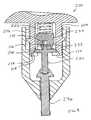
Fig. 2 shows a controlledforce impacting tool 100 according to the invention having a contouredhandle 102 and ahousing 104 extending therefrom. An impactingrod 106 extends forwardly of thehousing 104. The impactingrod 106 includes a threadeddistal end 108 that engages a threadedportion 110 of anappropriate impacting tip 112 as shown inFIG. 3 . The impactingtip 112 includes a curvilinearinternal cavity 114 conformed to mate with a replacement component such as thefemoral head 12. In accordance with the present invention, a plurality of impacting tips may be provided, such as in a kit. Each of the plurality of impacting tips may be configured to mate respectively with one of a plurality of replacement components of different types and of different sizes. - The internal components of the impacting
tool 100 are best seen inFIGS. 4-6 . Thehousing 104 is hollow. An impactingspring compartment 116 is separated from apush rod compartment 118 by a centeringhole 120. An impactingpiston 122 is disposed adjacent to an impactingspring 124 within the impactingspring compartment 116. The impactingpiston 122 includes acentral bore 126 with aclosed end 128. - A
push rod 130 and abiasing spring 132 are disposed within thepush rod compartment 118. Thepush rod 130 includes a roundeddistal end 134, ashoulder region 136 and astem 138. Thestem 138 is configured to pass through the centeringhole 120 and to fit within thecentral bore 126 as is discussed more fully below. The roundeddistal end 134 of thepush rod 130 is configured to contact the roundedproximal end 140 of the impactingrod 106. The biasingspring 132 is configured such that when there is no force being applied to the contouredhandle 102, thestem 138 is biased toward a position outside of thecentral bore 126. The biasingspring 132 further biases thestem 138 laterally away from thecentral bore 126 toward a solid portion of the distal end of the impactingpiston 122 as shown inFIG. 6 . - The rounded
proximal end 140 and acollar 142 of the impactingrod 106 are also located within thepush rod compartment 118. Thecollar 142 cooperates with aledge 144 in thehousing 104 to maintain the roundedproximal end 140 of the impactingrod 106 within thepush rod compartment 118. The impactingrod 106 extends from within thepush rod compartment 118 through abore 146 formed in thehousing 104 to a position forward of thehousing 104. - Turning to the operation of the embodiment of the invention shown in
FIG. 2 , the replacement components to be joined together are positioned so that, in the case of a Morse taper lock, the plug of a first component is located snugly within the receptacle of a second component. The appropriate impacting tip such as the impactingtip 112 is then selected and mounted on the threadeddistal end 108 of the impactingrod 106. The impacting tip is selected such that a large surface area of theinternal cavity 114 of the impactingtip 112 will contact the component to be driven. Of course, other modes of engaging impacting tips with the impacting rod are contemplated within the scope of the present invention in addition to modes using threaded engagement. Such modes include, but are not limited to, modes used to provide so-called "quick disconnect" engagement. - Next, the impacting
tip 112 is placed in position over the component to be driven. At this point, the impactingtool 100 is in the condition shown inFIG. 4 . Thus, the impactingspring 124 is fully extended and the impactingpiston 122 is at the distal end of the impactingspring compartment 116. Since there is no pressure applied to the contouredhandle 102, the biasingspring 132 is also fully extended both axially and laterally with respect to the axis of the impactingtool 100. Thus, thepush rod 130 is forced against the impactingrod 106 with thecollar 142 against theledge 144 of thehousing 104. - With the biasing
spring 132 fully extended, thestem 138 extends through the centeringhole 120 but is maintained outside of thecentral bore 126 of the impactingpiston 122. The biasingspring 132 further biases thestem 138 about 10 to 15 degrees off of the centerline of the centeringhole 120. In this position, thestem 138 is adjacent to a solid portion of the distal end of the impactingpiston 122. - The
impact tool 100 is operated by forcing the contouredhandle 102 toward the impactingtip 112 so as to begin to compress thebiasing spring 132. This causes the impactingrod 106 to be forced against thepush rod 130. More precisely, the roundedproximal end 140 of the impactingrod 106 is forced against the roundeddistal end 134 of thepush rod 130. Even though the impactingrod 106 and thepush rod 130 are not aligned because of the bias exerted on thepush rod 130 by the biasingspring 132, solid contact between the impactingrod 106 and thepush rod 130 is provided because both the roundedproximal end 140 of the impactingrod 106 and the roundeddistal end 134 of thepush rod 130 are complimentarily rounded. - Because the proximal end of the
stem 138 is not aligned with thecentral bore 126 of the impactingpiston 122, continued pushing on the contouredhandle 102 forces thestem 138 against the distal end of the impactingpiston 122 which in turn begins to compress the impactingspring 124. Of course, any suitable mechanism could be used to compress the impacting spring such as, but not limited to, directly pulling the impacting spring into a compressed condition. As the impactingspring 124 is compressed, more of the impactingrod 106 is forced into thehousing 104 as thecontoured handle 102, thepush rod 130 and the impactingpiston 122 are forced toward the impactingtip 112. This continues until the impactingtool 100 is in the condition shown inFIG. 5 . - In
FIG. 5 , theshoulder region 136 of thepush rod 130 is not in contact with the sides of the centeringhole 120. Thus, stem 138 is still forced against the impactingpiston 122 and thepush rod 130 is canted within thepush rod compartment 118. The impactingspring 124 is in a compressed condition, with a large amount of energy stored in the impactingspring 124 due to the compression. As the surgeon continues to press upon the contouredhandle 102, theshoulder region 136 is forced against the side of the centeringhole 120. - The
shoulder region 136 and the centeringhole 120 are formed such that as theshoulder region 136 is forced against the side of the centeringhole 120, thepush rod 130 will become aligned with the centeringhole 120. In the embodiment ofFIG. 5 , this is accomplished by forming both theshoulder region 136 and the side of the centeringhole 120 in the shape of complimentary frustums. As thepush rod 130 is aligned with thecenter hole 120, thestem 138 of thepush rod 130 is forced laterally toward thecentral bore 126 of the impactingpiston 122. As theshoulder region 136 becomes seated on the side of the centeringhole 120, thestem 138 is brought into alignment with thecentral bore 126 as shown inFIG. 6 . - Since the
stem 138 is aligned with thecentral bore 126 of the impactingpiston 122, the impactingspring 124 is no longer being forced into compression by the force applied to the contouredhandle 102. This is referred to herein as a "triggered condition". Accordingly, the impactingspring 124 is allowed to release the energy stored by compression of the impactingspring 124 and to accelerate the impactingpiston 122 toward thepush rod 130. Thus, in this embodiment, theshoulder region 136 of thepush rod 130 in combination with the side of the centeringhole 120 comprise a trigger mechanism which may be used to release the energy stored within the impactingspring 124. Of course, other centering devices, such as a ramp or a lever, or other release mechanisms could be used as a trigger mechanism. - Because the
stem 138 is longer than the depth of thebore 126, the first contact between thepush rod 130 and the impactingpiston 122 after the impact tool is triggered occurs when theclosed end 128 of thecentral bore 126 impacts thestem 138. As theclosed end 128 of thecentral bore 126 impacts thestem 138, force in the form of the momentum of the impactingpiston 122 and some residual compression of the impactingspring 124 is transferred to thepush rod 130. This force is in turn transferred to the impactingrod 106 and then to the impactingtip 112 and into the component being impacted. - The
impact tool 100 may then be removed from the component being impacted. This allows the biasingspring 132 to force thepush rod 130 axially toward the distal end of the impactingtool 100. As thepush rod 130 moves, thestem 138 will be moved completely outside of thecentral bore 126 of the impactingpiston 122. At this point, the biasingspring 132 further forces thestem 138 in a lateral direction, moving thestem 138 out of alignment with thecentral bore 126 and resetting the impactingtool 100 for another cycle. - As will be apparent from the description above, the amount of force transferred to the impacting
rod 106 is the result of certain variables which may be selected to provide the desired force for a particular impaction. For example, the spring constants of the impacting spring and the biasing spring both contribute to the amount of energy transferred to the impacting rod. Additionally, the mass of the impacting piston and the depth of the central bore and the length of the stem on the push rod affect the amount of momentum that is generated and subsequently transferred to the impacting rod. Accordingly, a wide variety of impacting tool configurations are provided according to the present invention. - Additionally, the impacting tool can be made in any suitable size. In one configuration, the impacting tool may be the size of a syringe and the contoured handle may be configured to receive a thumb to allow for use with one hand. In another embodiment, the impacting tool may be large enough to be provided with a hand grip around the housing while the contoured handle is configured to be pressed with the palm of a user.
- Of course, the final amount of force transferred to the orthopaedic component will also vary according to certain variables which in this embodiment are not considered design variables. By way of example, the rapidity with which the impacting spring in the embodiment of
FIG. 2 is being compressed at the moment of triggering will have some affect on the final amount of impacting force that is transferred to the orthopaedic component. Nonetheless, by selection of the above discussed design variables, even allowing for some non-design variables, the amount of force that is transferred to the orthopaedic component is sufficiently controlled. Thus, a force that is sufficient to produce the desired effect while minimizing excessive force, that is, a controlled force, is transferred to the orthopaedic component. - Referring now to
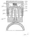
FIG. 7 , an alternative controlledforce impacting tool 200 according to the invention includes a contouredhandle 202 with two triggeringarms arms stubs grooves outer housing 216. At the distal end of the triggeringarms shoulders - An impacting
spring 222 is located between the triggeringarms handle 202 as shown inFIG. 7 . An impactingpiston 224 is located at the distal end of the impactingspring 222. The impactingpiston 224 includes acentral bore 226 with aclosed end 228. - A
push rod 230 and abiasing spring 232 are disposed within a push rod compartment 234 formed by theouter housing 216. Thepush rod 230 includes a rounded distal end 236, abeveled collar 238 and astem 240. Thestem 240 is configured to fit within thecentral bore 226 as is discussed more fully below. The biasingspring 232 is fixedly attached to thepush rod 230 at one end and to the impactingpiston 224 at the other end. The biasingspring 232 is configured such that when there is no force being applied to the contouredhandle 202, thestem 240 is biased axially toward a position outside of thecentral bore 226. The biasingspring 232 further biases thestem 240 laterally away from thecentral bore 226 toward a solid portion of the distal end of the impactingpiston 224. - The rounded distal end 236 of the
push rod 230 is configured to contact therounded end 242 of a retaining well 244 on the impactingrod 246. The impactingrod 246 includes acollar 248 that cooperates with aledge 250 in theouter housing 216 to maintain the roundedproximal end 242 of the impactingrod 244 within the push rod compartment 234. The impactingrod 246 further includes a threadeddistal end 254. The impactingrod 246 extends from within the push rod compartment 234 through abore 252 formed by theouter housing 216. - The
outer housing 216 is not used to maintain thepush rod 230 properly aligned within the push rod compartment 234 in this embodiment. Rather, the retaining well 244 is used to ensure that thepush rod 230 is roughly aligned with the impactingrod 246. Specifically, thepush rod 230 is not maintained fixedly against the impactingrod 246 by the biasingspring 232. Thus, if the impactingrod 246 is not mounted to or pressed against another object, then the impactingrod 246 is free to move away from thepush rod 230 until thecollar 248 rests against theledge 250 in theouter housing 216. However, the retaining well 244 is configured with walls that are sufficiently high such that even in this condition, the rounded distal end 236 of thepush rod 230 will still be within the retaining well 244. Thus, when thepush rod 230 and the impactingrod 246 are pressed toward each other, the retaining well ensures that the rounded distal end 236 of thepush rod 230 will sufficiently align with therounded end 242 of the retaining well 244 on the impactingrod 246 to transfer force between the two rods. - The operation of the embodiment of the invention shown in
FIG. 7 is similar to the operation of the embodiment ofFIG. 2 . Initially, the impactingtool 200 is in the condition shown inFIG. 7 with the impactingspring 222 fully extended. Since there is no pressure applied to the contouredhandle 202, the biasingspring 232 is also fully extended and the rounded distal end 236 of thepush rod 230 is located within the retaining well 244 of the impactingrod 246. - With the biasing
spring 232 fully extended, thestem 240 is maintained outside of thecentral bore 226 of the impactingpiston 224. The biasingspring 232 further biases thestem 240 about 10 to 15 degrees off of the centerline of thecentral bore 226. In this position, thestem 240 is adjacent to a solid portion of the end of the impactingpiston 224. - If desired, an impacting tip may be threaded onto the threaded
distal end 254. The impacting tool is then positioned such that the impacting tip or threadeddistal end 254 is positioned against the component to be impacted. Then, thehousing 216 is moved toward the component to be impacted. This causes the contouredhandle 202, the impactingspring 222, the impactingpiston 224, the biasingspring 232 and thepush rod 230 to move toward the component to be impacted. Thus, the rounded distal end 236 of thepush rod 230 is forced downward within the retaining well 244 until the rounded distal end 236 contacts therounded end 242 of the retaining well 244. Proper seating of the rounded distal end 236 and therounded end 242 is indicated by a rapid increase in resistance. - The impacting
tool 200 is then operated by forcing the contouredhandle 202 toward theouter housing 216. This causes the impactingspring 222 to be pushed toward the impactingpiston 224. If there is any space between the impactingpiston 224 and thepush rod 230, then the biasingspring 232 is compressed until the impactingpiston 224 and thepush rod 230 are in physical contact with each other. - Because the proximal end of the
stem 240 is not aligned with thecentral bore 226 of the impactingpiston 224, continued pushing on the contouredhandle 202 compresses the impactingspring 222. However, unlike the embodiment ofFIG. 2 , the impactingrod 246 does not necessarily move into theouter housing 216 as the impactingspring 222 is further compressed. Rather, theouter housing 216 may be moved axially either toward or away from the component to be impacted. - If desired, the housing may alternatively be maintained in a fixed relationship to the component to be impacted. This is possible since no portion of the housing is used as a part of the trigger mechanism. Thus, the movement of the
housing 216 is only constrained by the distance between theledge 250 and thecollar 248 and/or the position of thestubs grooves push rod 230 within the well. - Continuing with the operation of the impacting
tool 200, continued movement of the contoured handle 20 causes the impactingspring 222 to be further compressed and the targetingarms beveled collar 238 of thepush rod 230 until the impactingtool 200 is in the condition shown inFIG. 8 . - In
FIG. 8 , thebeveled shoulder 220 of the triggeringarm 204 is in contact with thebeveled collar 238 of thepush rod 230. However, thestem 240 is still forced against the impactingpiston 224 and thepush rod 230 is canted within the push rod compartment 234. The impactingspring 222 is in a compressed condition, with a large amount of energy stored in the impactingspring 222 due to the compression. As the surgeon continues to press upon the contouredhandle 202, thebeveled shoulder 220 pushes against thebeveled collar 238 and the lateral bias of the biasingspring 232 is overcome resulting in lateral movement of thestem 240 toward the center bore 226. As thebeveled collar 238 becomes seated against thebeveled shoulder 218 of the triggeringarm 206 and thebeveled shoulder 220 of the triggeringarm 204, thestem 240 is brought into alignment with thecentral bore 226 as shown inFIG. 9 . - Since the
stem 240 is aligned with thecentral bore 226 of the impactingpiston 224, the impactingtool 200 is in a triggered condition with the impactingspring 222 no longer being forced into compression between thecontoured handle 202 and thestem 240. Accordingly, the impactingspring 232 releases the energy stored by compression of the impactingspring 232 and accelerates the impactingpiston 224 toward thepush rod 230. Thus, in this embodiment, thebeveled collar 238 of thepush rod 230 in combination with thebeveled shoulder 220 comprise a trigger mechanism which may be used to release the energy stored within the impactingspring 232. - Because the
stem 240 is longer than the depth of thecentral bore 226, the first contact between thepush rod 230 and the impactingpiston 224 occurs when theclosed end 228 of thecentral bore 226 impacts thestem 240. As theclosed end 228 of thecentral bore 226 impacts thestem 240, energy in the form of the momentum of the impactingpiston 224 and some residual compression of the impactingspring 232 is transferred to thepush rod 230. The energy is in turn transferred to the impactingrod 246 and into the component being impacted. - Of course, in this embodiment the movement of the impacting
piston 224 after triggering forces the biasingspring 232 into compression. Therefore, some energy from the impactingspring 222 is absorbed by the biasingspring 232. This cushioning effect is an additional design consideration when selecting, for example, the spring constants of the impactingspring 222 and the biasingspring 232. - After the impact has been delivered, the force being applied to the contoured
handle 202 may be released. This allows any remaining compression of the impactingspring 222 and the biasingspring 232 to be released. Thus, the contouredhandle 202 is moved axially away from the impactingpiston 224 and the biasingspring 232 forces the impactingpiston 224 away from thepush rod 230. This causes thebeveled collar 238 to be moved away from thebeveled shoulders arms spring 232 decompresses, the impactingpiston 224 will be moved such that thestem 240 will be completely outside of thecentral bore 226 of the impactingpiston 224. Since the lateral position of thestem 240 is no longer constrained by thebeveled shoulders spring 232 forces thestem 240 in a lateral direction, moving thestem 240 out of alignment with thecentral bore 226 and resetting the impactingtool 200 for another cycle. - The various impacting tips described above may incorporate alignment aids so as to assist in optimally aligning the impacting tools with the component to be impacted.
Such alignment aids may include providing the impacting tip with a key that mates with a corresponding receptacle on the component to be impacted. Alternatively, the impacting tip and component to be impacted may be complimentarily shaped so as to make only when properly aligned. By properly aligning the impacting device, the force needed to either implant a component or to form a Morse tape lock is minimized.
Claims (11)
- A controlled force orthopaedic component impacting tool (100, 200) comprising:a housing (104, 216);an impacting rod (106, 246) having a first end portion extending upward within the housing (104, 216) and a second end portion configured to transfer force to an orthopaedic component;an impacting piston (122, 224) positioned above the first end portion of the impacting rod (106, 246) and operable to transfer force to the impacting rod (106, 246);an impacting spring (124, 222) operably connected to the impacting piston (122, 224) to transfer force to the impacting piston (122, 224); anda trigger mechanism operable to effect the release of energy stored within the impacting spring (124, 222), such that the spring (124, 222) acts upon the impacting piston (122, 224) and a controlled amount of force is transferred from the impacting piston (122, 224) through the impacting rod (106, 246) to the orthopaedic component;characterized in that said trigger mechanism comprises:the first end portion of the impacting rod (106, 246) being curved;the impacting piston (122, 224) having a central bore (128, 228) with a closed end; andthe impacting tool (100, 200) further comprising:a push rod (130, 230) located between the impacting piston (122, 224) and the impacting rod (106, 246) and having (i) a stem with a length greater than the depth of the central bore (128, 228) and configured to fit within the central bore (128, 228) and (ii) an end portion curved complimentarily to the curved first end portion of the impacting rod (106, 246); anda biasing spring (132, 232) operable to bias the stem of the push rod (130, 230) in a direction laterally away from the central bore (128, 228).
- A tool (100, 200) as claimed in claim 1, wherein the second end portion is configured as an orthopaedic component impacting tip.
- A tool (100, 200) as claimed in claim 2, wherein the second end portion comprises a curvilinear internal cavity configured to mate with the orthopaedic component.
- A tool (100, 200) as claimed in claim 3, wherein the curvilinear internal cavity is configured to mate with the head of the orthopaedic component.
- A tool (100, 200) as claimed in claim 1, wherein the second end portion is configured to mate with at least one impacting tip.
- A tool (100, 200) as claimed in claim 5, wherein the second end portion is configured to mate with a plurality of impacting tips, each of the plurality of impacting tips configured to mate with an orthopaedic component of a different size or shape.
- A tool (100) as claimed in claim 1, wherein;the housing (104) comprises a wall defining a centering hole (120);the stem of the push rod (130) is configured to fit through the centering hole (120); andthe push rod (130) comprises a shoulder region (136) configured to seat on the wall defining the centering hole (120) such that when the shoulder region (136) is seated on the wall defining the centering hole (120), the stem is aligned with the central bore (128).
- A tool (200) as claimed in claim 1, wherein:the impacting tool (200) further comprises a handle (202) movable with respect to the housing (216) and operably connected to the impacting spring (124) to compress the impacting spring (124), the handle (202) having a plurality of trigger arms (204, 206) extending downwardly therefrom; andthe push rod (230) comprises a shoulder region configured to seat on the trigger arms (204, 206) such that when the shoulder region is seated on the trigger arms (204, 206), the stem is aligned with the central bore (228).
- A tool (100, 200) as claimed in claim 8, wherein the first end portion of the impacting rod (246) further comprises:a well portion (244) configured to extend upwardly within the housing (216) and to align the curved end portion of the push rod (230) with the curved first end portion of the impacting rod (246).
- A kit for providing an impact to an orthopaedic implant, the kit comprising:an impacting tool (100, 200) according to claim 1; anda plurality of impacting tips, each of the plurality of impacting tips i) removably engageable with the impacting rod and ii) configured to mate with an orthopaedic component different from the orthopaedic component with which another of the plurality of impacting tips is configured to mate.
- The kit of claim 10, wherein at least one of the plurality of impacting tips comprises a curvilinear internal cavity configured to mate with a portion of the orthopaedic component to be impacted.
Priority Applications (1)
| Application Number | Priority Date | Filing Date | Title |
|---|---|---|---|
| EP08001270AEP1923023B1 (en) | 2005-03-31 | 2006-03-31 | Controlled force impacting device |
Applications Claiming Priority (1)
| Application Number | Priority Date | Filing Date | Title |
|---|---|---|---|
| US11/094,929US7708739B2 (en) | 2005-03-31 | 2005-03-31 | Controlled force impacting device |
Related Child Applications (1)
| Application Number | Title | Priority Date | Filing Date |
|---|---|---|---|
| EP08001270ADivisionEP1923023B1 (en) | 2005-03-31 | 2006-03-31 | Controlled force impacting device |
Publications (2)
| Publication Number | Publication Date |
|---|---|
| EP1707160A1 EP1707160A1 (en) | 2006-10-04 |
| EP1707160B1true EP1707160B1 (en) | 2009-01-07 |
Family
ID=36607550
Family Applications (2)
| Application Number | Title | Priority Date | Filing Date |
|---|---|---|---|
| EP06251813ANot-in-forceEP1707160B1 (en) | 2005-03-31 | 2006-03-31 | Controlled force impacting device |
| EP08001270ANot-in-forceEP1923023B1 (en) | 2005-03-31 | 2006-03-31 | Controlled force impacting device |
Family Applications After (1)
| Application Number | Title | Priority Date | Filing Date |
|---|---|---|---|
| EP08001270ANot-in-forceEP1923023B1 (en) | 2005-03-31 | 2006-03-31 | Controlled force impacting device |
Country Status (6)
| Country | Link |
|---|---|
| US (1) | US7708739B2 (en) |
| EP (2) | EP1707160B1 (en) |
| JP (1) | JP4708247B2 (en) |
| AT (2) | ATE419813T1 (en) |
| AU (1) | AU2006201315B2 (en) |
| DE (2) | DE602006006916D1 (en) |
Families Citing this family (32)
| Publication number | Priority date | Publication date | Assignee | Title |
|---|---|---|---|---|
| US20100076370A1 (en) | 2008-09-23 | 2010-03-25 | Infusion Advancements, LLC. | Apparatus and methods for purging catheter systems |
| WO2012015592A2 (en)* | 2010-07-28 | 2012-02-02 | The Regents Of The University Of California | Method and device for reference point indentation without a reference probe |
| US20120024117A1 (en)* | 2010-07-29 | 2012-02-02 | Kreutzer Robert E | Starter Tool |
| US8695726B2 (en) | 2010-12-29 | 2014-04-15 | Medical Enterprises LLC | Electric motor driven tool for orthopedic impacting |
| US8393409B2 (en) | 2010-12-29 | 2013-03-12 | Ortho Technologies, Llc | Electric motor driven tool for orthopedic impacting |
| CN104519813A (en) | 2010-12-29 | 2015-04-15 | 澳擞技术有限责任公司 | Motor-driven tools for orthopedic impact |
| EP2704652A4 (en)* | 2011-05-03 | 2015-06-10 | Biodynamics Llc | Bone tack driver |
| US8771324B2 (en) | 2011-05-27 | 2014-07-08 | Globus Medical, Inc. | Securing fasteners |
| US10149711B2 (en) | 2012-03-30 | 2018-12-11 | Depuy Mitek, Llc | Surgical impact tool |
| US8900245B2 (en)* | 2012-06-07 | 2014-12-02 | Howmedica Osteonics Corp. | Glenosphere inserter and impactor |
| US9005213B2 (en) | 2012-11-16 | 2015-04-14 | DePuy Synthes Products, Inc. | Controlled force surgical implant impaction instrument |
| WO2015109203A2 (en)* | 2014-01-16 | 2015-07-23 | Archer Sciences, LLC | Impactor and remover devices |
| FR3018187B1 (en)* | 2014-03-07 | 2022-05-27 | Xnov Ip | DEVICE FOR INSERTING AN INSERT BY IMPACTION INTO A CUP INTENDED TO BE RECEIVED IN THE HIP COTYLE |
| US9687287B2 (en) | 2014-06-19 | 2017-06-27 | Biomet Manufacturing, Llc | Impact load-limiting surgical impactor |
| CN105643555A (en)* | 2014-11-14 | 2016-06-08 | 富泰华工业(深圳)有限公司 | Overload protection pressing device |
| GB201514727D0 (en) | 2015-08-19 | 2015-09-30 | Depuy Ireland | An Assembly Tool |
| FR3040290B1 (en)* | 2015-09-02 | 2022-01-14 | Xnov Ip | IMPACTOR DEVICE TO APPLY A SHOCK TO A ROD |
| US10682237B2 (en)* | 2015-09-03 | 2020-06-16 | Cmc Sert Ltd. | Prosthesis for replacing joint in a human hand or foot |
| CN105193462A (en)* | 2015-09-25 | 2015-12-30 | 常州麟喃热处理厂 | Power-assisted malleus ripper |
| GB201610820D0 (en)* | 2016-04-27 | 2016-08-03 | Depuy (Ireland) | An impactor |
| US10709581B2 (en)* | 2016-08-17 | 2020-07-14 | Joint Innovation Technology Llc | Thermally securing Morse taper |
| TWI676534B (en)* | 2017-03-29 | 2019-11-11 | 美商米沃奇電子工具公司 | Punchdown tool |
| US11013503B2 (en) | 2017-05-26 | 2021-05-25 | DePuy Synthes Products, Inc. | Orthopedic device delivering a controlled, repeatable impact |
| AU2018279732B2 (en) | 2017-06-09 | 2024-03-07 | Mako Surgical Corp. | Systems and tools for positioning workpieces with surgical robots |
| WO2020070244A1 (en) | 2018-10-04 | 2020-04-09 | Depuy Ireland Unlimited Company | Prosthesis extraction system |
| CN109363763A (en)* | 2018-10-10 | 2019-02-22 | 付华玲 | A kind of intelligence spicule fastener driving device |
| DE102018125190B4 (en)* | 2018-10-11 | 2021-09-02 | Endocon Gmbh | Impact instrument for joining prosthetic implants |
| KR102254406B1 (en)* | 2019-05-27 | 2021-05-21 | 주식회사 덴티움 | Impactor for practicing medical operation |
| CN111067614A (en)* | 2019-12-30 | 2020-04-28 | 创美得医疗器械(天津)有限公司 | Novel adjustable torsion handle |
| US12186003B2 (en) | 2020-12-15 | 2025-01-07 | Moxie Medical, LLC | Bi-directional pneumatic impactor for orthopedic devices |
| CN114431946A (en)* | 2021-07-06 | 2022-05-06 | 皖南医学院第一附属医院(皖南医学院弋矶山医院) | A method of pulling out an intramedullary nail |
| DE102022118986A1 (en)* | 2022-07-28 | 2024-02-08 | Aesculap Ag | Medical percussion instrument |
Family Cites Families (24)
| Publication number | Priority date | Publication date | Assignee | Title |
|---|---|---|---|---|
| US2437014A (en)* | 1944-08-19 | 1948-03-02 | Nat Electric Instr Company Inc | Dental and surgical hammer |
| US2421354A (en)* | 1946-06-05 | 1947-05-27 | Reiter David | Surgical instrument with mallet action |
| US2725878A (en)* | 1954-09-20 | 1955-12-06 | Union Broach Co Inc | Surgical mallet structure |
| US2960864A (en)* | 1956-04-26 | 1960-11-22 | Amp Inc | Insertion tool |
| US3210836A (en)* | 1963-05-21 | 1965-10-12 | United Carr Inc | Electrical component remover and/or inserter |
| US4653486A (en)* | 1984-04-12 | 1987-03-31 | Coker Tom P | Fastener, particularly suited for orthopedic use |
| JPH02232176A (en)* | 1989-03-02 | 1990-09-14 | Kazunori Ikegami | Automatic impact type driver |
| US5037424A (en)* | 1989-12-21 | 1991-08-06 | Aboczsky Robert I | Instrument for orienting, inserting and impacting an acetabular cup prosthesis |
| US5116339A (en)* | 1990-07-11 | 1992-05-26 | Glock Steven R | Acetabular cup installation tool and method of installing an acetabular cup |
| US5171243A (en)* | 1991-02-13 | 1992-12-15 | Pfizer Hospital Products Group, Inc. | Acetabular cup positioning insert |
| US5169399A (en) | 1991-10-17 | 1992-12-08 | Boehringer Mannheim Corporation | Acetabular cup impactor |
| US5584837A (en)* | 1993-08-13 | 1996-12-17 | Petersen; Thomas D. | Acetabular cup inserter for orthopedic |
| US5431657A (en)* | 1994-05-23 | 1995-07-11 | Zimmer, Inc. | Instrument for installing an acetabular cup assembly |
| US5486181A (en)* | 1994-08-04 | 1996-01-23 | Implex Corporation | Acetabular cup, method and tool and installing the same |
| DE19509966A1 (en)* | 1995-03-18 | 1996-09-19 | Frank Ullrich Schuetz | Stapler and nail for surgery |
| US5735855A (en)* | 1996-10-25 | 1998-04-07 | Bradley; Gary W. | Automatic impact device |
| US6004326A (en)* | 1997-09-10 | 1999-12-21 | United States Surgical | Method and instrumentation for implant insertion |
| US6370993B1 (en)* | 1999-07-13 | 2002-04-16 | Martin H. Pitstick | Spring loaded self actuating impact driver |
| FR2814065B1 (en) | 2000-09-20 | 2005-06-17 | Oreal | WASHING COMPOSITION COMPRISING ALUMINUM OXIDE PARTICLES, AT LEAST ONE ANIONIC SURFACTANT AND AT LEAST ONE AMPHOTERIC OR NON-IONIC SURFACTANT |
| FR2814061B1 (en)* | 2000-09-21 | 2003-02-21 | Sulzer Orthopedie S A | IMPACTOR FOR THE ORTHOPEDIC AREA |
| EP1394639B1 (en)* | 2001-05-17 | 2011-04-13 | Citizen Holdings Co., Ltd. | Tool for wristwatch |
| ES2254574T3 (en)* | 2002-08-30 | 2006-06-16 | Zimmer Gmbh | OPERATING SYSTEM. |
| US7172598B2 (en)* | 2002-09-30 | 2007-02-06 | Depuy Products, Inc. | Force specific impacting device |
| US7708743B2 (en)* | 2005-04-29 | 2010-05-04 | Warsaw Orthopedic, Inc. | Apparatus and method for positioning an implant during surgery |
- 2005
- 2005-03-31USUS11/094,929patent/US7708739B2/ennot_activeExpired - Lifetime
- 2006
- 2006-03-29AUAU2006201315Apatent/AU2006201315B2/ennot_activeCeased
- 2006-03-30JPJP2006094465Apatent/JP4708247B2/ennot_activeExpired - Fee Related
- 2006-03-31ATAT06251813Tpatent/ATE419813T1/ennot_activeIP Right Cessation
- 2006-03-31ATAT08001270Tpatent/ATE431729T1/ennot_activeIP Right Cessation
- 2006-03-31EPEP06251813Apatent/EP1707160B1/ennot_activeNot-in-force
- 2006-03-31EPEP08001270Apatent/EP1923023B1/ennot_activeNot-in-force
- 2006-03-31DEDE602006006916Tpatent/DE602006006916D1/enactiveActive
- 2006-03-31DEDE602006004630Tpatent/DE602006004630D1/enactiveActive
Also Published As
| Publication number | Publication date |
|---|---|
| JP4708247B2 (en) | 2011-06-22 |
| EP1923023B1 (en) | 2009-05-20 |
| DE602006004630D1 (en) | 2009-02-26 |
| AU2006201315A1 (en) | 2006-10-19 |
| EP1923023A2 (en) | 2008-05-21 |
| ATE419813T1 (en) | 2009-01-15 |
| ATE431729T1 (en) | 2009-06-15 |
| US20060241631A1 (en) | 2006-10-26 |
| JP2006280946A (en) | 2006-10-19 |
| AU2006201315B2 (en) | 2010-08-19 |
| EP1707160A1 (en) | 2006-10-04 |
| EP1923023A3 (en) | 2008-06-04 |
| US7708739B2 (en) | 2010-05-04 |
| DE602006006916D1 (en) | 2009-07-02 |
Similar Documents
| Publication | Publication Date | Title |
|---|---|---|
| EP1707160B1 (en) | Controlled force impacting device | |
| US10596011B2 (en) | Orthopaedic surgical instrument and method for positioning an acetabular prosthetic component | |
| JP3949765B2 (en) | Artificial knee joint implant tool system and universal tool | |
| EP2502580B1 (en) | Pneumatic surgical instrument | |
| EP1813229B1 (en) | Split thread orthopaedic implant impactor | |
| US5827290A (en) | Automatic impact device | |
| US9005213B2 (en) | Controlled force surgical implant impaction instrument | |
| EP2055274B1 (en) | Taper Sleeve Extractor | |
| US8152814B2 (en) | Separator tool for a modular prosthesis | |
| JP2019524165A (en) | Orthopedic device for delivering controlled and repeatable impacts | |
| WO2014091454A1 (en) | Universal impactor with slap hammer | |
| US12193718B2 (en) | Orthopedic surgical instrument | |
| US11957395B2 (en) | Orthopedic instrument adapters | |
| US12383324B2 (en) | Straight and curved femoral broach impactor adapters | |
| EP2301484B1 (en) | A method of assembling an implant |
Legal Events
| Date | Code | Title | Description |
|---|---|---|---|
| PUAI | Public reference made under article 153(3) epc to a published international application that has entered the european phase | Free format text:ORIGINAL CODE: 0009012 | |
| AK | Designated contracting states | Kind code of ref document:A1 Designated state(s):AT BE BG CH CY CZ DE DK EE ES FI FR GB GR HU IE IS IT LI LT LU LV MC NL PL PT RO SE SI SK TR | |
| AX | Request for extension of the european patent | Extension state:AL BA HR MK YU | |
| 17P | Request for examination filed | Effective date:20070302 | |
| 17Q | First examination report despatched | Effective date:20070329 | |
| AKX | Designation fees paid | Designated state(s):AT BE BG CH CY CZ DE DK EE ES FI FR GB GR HU IE IS IT LI LT LU LV MC NL PL PT RO SE SI SK TR | |
| GRAP | Despatch of communication of intention to grant a patent | Free format text:ORIGINAL CODE: EPIDOSNIGR1 | |
| RIN1 | Information on inventor provided before grant (corrected) | Inventor name:CASSELL, DENNIS Inventor name:SCHNEIDERS, BARRY Inventor name:KILBURN, RANDY | |
| GRAS | Grant fee paid | Free format text:ORIGINAL CODE: EPIDOSNIGR3 | |
| GRAA | (expected) grant | Free format text:ORIGINAL CODE: 0009210 | |
| AK | Designated contracting states | Kind code of ref document:B1 Designated state(s):AT BE BG CH CY CZ DE DK EE ES FI FR GB GR HU IE IS IT LI LT LU LV MC NL PL PT RO SE SI SK TR | |
| REG | Reference to a national code | Ref country code:GB Ref legal event code:FG4D | |
| REG | Reference to a national code | Ref country code:CH Ref legal event code:NV Representative=s name:E. BLUM & CO. AG PATENT- UND MARKENANWAELTE VSP Ref country code:CH Ref legal event code:EP | |
| REG | Reference to a national code | Ref country code:IE Ref legal event code:FG4D | |
| REF | Corresponds to: | Ref document number:602006004630 Country of ref document:DE Date of ref document:20090226 Kind code of ref document:P | |
| PG25 | Lapsed in a contracting state [announced via postgrant information from national office to epo] | Ref country code:NL Free format text:LAPSE BECAUSE OF FAILURE TO SUBMIT A TRANSLATION OF THE DESCRIPTION OR TO PAY THE FEE WITHIN THE PRESCRIBED TIME-LIMIT Effective date:20090107 Ref country code:SI Free format text:LAPSE BECAUSE OF FAILURE TO SUBMIT A TRANSLATION OF THE DESCRIPTION OR TO PAY THE FEE WITHIN THE PRESCRIBED TIME-LIMIT Effective date:20090107 | |
| NLV1 | Nl: lapsed or annulled due to failure to fulfill the requirements of art. 29p and 29m of the patents act | ||
| PG25 | Lapsed in a contracting state [announced via postgrant information from national office to epo] | Ref country code:ES Free format text:LAPSE BECAUSE OF FAILURE TO SUBMIT A TRANSLATION OF THE DESCRIPTION OR TO PAY THE FEE WITHIN THE PRESCRIBED TIME-LIMIT Effective date:20090418 Ref country code:FI Free format text:LAPSE BECAUSE OF FAILURE TO SUBMIT A TRANSLATION OF THE DESCRIPTION OR TO PAY THE FEE WITHIN THE PRESCRIBED TIME-LIMIT Effective date:20090107 Ref country code:LT Free format text:LAPSE BECAUSE OF FAILURE TO SUBMIT A TRANSLATION OF THE DESCRIPTION OR TO PAY THE FEE WITHIN THE PRESCRIBED TIME-LIMIT Effective date:20090107 | |
| PG25 | Lapsed in a contracting state [announced via postgrant information from national office to epo] | Ref country code:LV Free format text:LAPSE BECAUSE OF FAILURE TO SUBMIT A TRANSLATION OF THE DESCRIPTION OR TO PAY THE FEE WITHIN THE PRESCRIBED TIME-LIMIT Effective date:20090107 Ref country code:IS Free format text:LAPSE BECAUSE OF FAILURE TO SUBMIT A TRANSLATION OF THE DESCRIPTION OR TO PAY THE FEE WITHIN THE PRESCRIBED TIME-LIMIT Effective date:20090507 Ref country code:AT Free format text:LAPSE BECAUSE OF FAILURE TO SUBMIT A TRANSLATION OF THE DESCRIPTION OR TO PAY THE FEE WITHIN THE PRESCRIBED TIME-LIMIT Effective date:20090107 Ref country code:PL Free format text:LAPSE BECAUSE OF FAILURE TO SUBMIT A TRANSLATION OF THE DESCRIPTION OR TO PAY THE FEE WITHIN THE PRESCRIBED TIME-LIMIT Effective date:20090107 Ref country code:PT Free format text:LAPSE BECAUSE OF FAILURE TO SUBMIT A TRANSLATION OF THE DESCRIPTION OR TO PAY THE FEE WITHIN THE PRESCRIBED TIME-LIMIT Effective date:20090608 Ref country code:SE Free format text:LAPSE BECAUSE OF FAILURE TO SUBMIT A TRANSLATION OF THE DESCRIPTION OR TO PAY THE FEE WITHIN THE PRESCRIBED TIME-LIMIT Effective date:20090407 | |
| PG25 | Lapsed in a contracting state [announced via postgrant information from national office to epo] | Ref country code:BE Free format text:LAPSE BECAUSE OF FAILURE TO SUBMIT A TRANSLATION OF THE DESCRIPTION OR TO PAY THE FEE WITHIN THE PRESCRIBED TIME-LIMIT Effective date:20090107 | |
| PG25 | Lapsed in a contracting state [announced via postgrant information from national office to epo] | Ref country code:CZ Free format text:LAPSE BECAUSE OF FAILURE TO SUBMIT A TRANSLATION OF THE DESCRIPTION OR TO PAY THE FEE WITHIN THE PRESCRIBED TIME-LIMIT Effective date:20090107 Ref country code:EE Free format text:LAPSE BECAUSE OF FAILURE TO SUBMIT A TRANSLATION OF THE DESCRIPTION OR TO PAY THE FEE WITHIN THE PRESCRIBED TIME-LIMIT Effective date:20090107 Ref country code:MC Free format text:LAPSE BECAUSE OF NON-PAYMENT OF DUE FEES Effective date:20090331 Ref country code:DK Free format text:LAPSE BECAUSE OF FAILURE TO SUBMIT A TRANSLATION OF THE DESCRIPTION OR TO PAY THE FEE WITHIN THE PRESCRIBED TIME-LIMIT Effective date:20090107 | |
| PLBE | No opposition filed within time limit | Free format text:ORIGINAL CODE: 0009261 | |
| STAA | Information on the status of an ep patent application or granted ep patent | Free format text:STATUS: NO OPPOSITION FILED WITHIN TIME LIMIT | |
| PG25 | Lapsed in a contracting state [announced via postgrant information from national office to epo] | Ref country code:SK Free format text:LAPSE BECAUSE OF FAILURE TO SUBMIT A TRANSLATION OF THE DESCRIPTION OR TO PAY THE FEE WITHIN THE PRESCRIBED TIME-LIMIT Effective date:20090107 Ref country code:RO Free format text:LAPSE BECAUSE OF FAILURE TO SUBMIT A TRANSLATION OF THE DESCRIPTION OR TO PAY THE FEE WITHIN THE PRESCRIBED TIME-LIMIT Effective date:20090107 | |
| 26N | No opposition filed | Effective date:20091008 | |
| PG25 | Lapsed in a contracting state [announced via postgrant information from national office to epo] | Ref country code:BG Free format text:LAPSE BECAUSE OF FAILURE TO SUBMIT A TRANSLATION OF THE DESCRIPTION OR TO PAY THE FEE WITHIN THE PRESCRIBED TIME-LIMIT Effective date:20090407 | |
| PG25 | Lapsed in a contracting state [announced via postgrant information from national office to epo] | Ref country code:GR Free format text:LAPSE BECAUSE OF FAILURE TO SUBMIT A TRANSLATION OF THE DESCRIPTION OR TO PAY THE FEE WITHIN THE PRESCRIBED TIME-LIMIT Effective date:20090408 | |
| PG25 | Lapsed in a contracting state [announced via postgrant information from national office to epo] | Ref country code:IT Free format text:LAPSE BECAUSE OF FAILURE TO SUBMIT A TRANSLATION OF THE DESCRIPTION OR TO PAY THE FEE WITHIN THE PRESCRIBED TIME-LIMIT Effective date:20090107 | |
| PG25 | Lapsed in a contracting state [announced via postgrant information from national office to epo] | Ref country code:LU Free format text:LAPSE BECAUSE OF NON-PAYMENT OF DUE FEES Effective date:20090331 | |
| PG25 | Lapsed in a contracting state [announced via postgrant information from national office to epo] | Ref country code:HU Free format text:LAPSE BECAUSE OF FAILURE TO SUBMIT A TRANSLATION OF THE DESCRIPTION OR TO PAY THE FEE WITHIN THE PRESCRIBED TIME-LIMIT Effective date:20090708 | |
| PG25 | Lapsed in a contracting state [announced via postgrant information from national office to epo] | Ref country code:TR Free format text:LAPSE BECAUSE OF FAILURE TO SUBMIT A TRANSLATION OF THE DESCRIPTION OR TO PAY THE FEE WITHIN THE PRESCRIBED TIME-LIMIT Effective date:20090107 | |
| PG25 | Lapsed in a contracting state [announced via postgrant information from national office to epo] | Ref country code:CY Free format text:LAPSE BECAUSE OF FAILURE TO SUBMIT A TRANSLATION OF THE DESCRIPTION OR TO PAY THE FEE WITHIN THE PRESCRIBED TIME-LIMIT Effective date:20090107 | |
| REG | Reference to a national code | Ref country code:FR Ref legal event code:PLFP Year of fee payment:11 | |
| REG | Reference to a national code | Ref country code:FR Ref legal event code:PLFP Year of fee payment:12 | |
| REG | Reference to a national code | Ref country code:FR Ref legal event code:PLFP Year of fee payment:13 | |
| PGFP | Annual fee paid to national office [announced via postgrant information from national office to epo] | Ref country code:IE Payment date:20220209 Year of fee payment:17 Ref country code:GB Payment date:20220210 Year of fee payment:17 Ref country code:DE Payment date:20220203 Year of fee payment:17 Ref country code:CH Payment date:20220215 Year of fee payment:17 | |
| PGFP | Annual fee paid to national office [announced via postgrant information from national office to epo] | Ref country code:FR Payment date:20220209 Year of fee payment:17 | |
| REG | Reference to a national code | Ref country code:DE Ref legal event code:R119 Ref document number:602006004630 Country of ref document:DE | |
| REG | Reference to a national code | Ref country code:CH Ref legal event code:PL | |
| GBPC | Gb: european patent ceased through non-payment of renewal fee | Effective date:20230331 | |
| REG | Reference to a national code | Ref country code:IE Ref legal event code:MM4A | |
| PG25 | Lapsed in a contracting state [announced via postgrant information from national office to epo] | Ref country code:GB Free format text:LAPSE BECAUSE OF NON-PAYMENT OF DUE FEES Effective date:20230331 | |
| PG25 | Lapsed in a contracting state [announced via postgrant information from national office to epo] | Ref country code:LI Free format text:LAPSE BECAUSE OF NON-PAYMENT OF DUE FEES Effective date:20230331 Ref country code:IE Free format text:LAPSE BECAUSE OF NON-PAYMENT OF DUE FEES Effective date:20230331 Ref country code:GB Free format text:LAPSE BECAUSE OF NON-PAYMENT OF DUE FEES Effective date:20230331 Ref country code:FR Free format text:LAPSE BECAUSE OF NON-PAYMENT OF DUE FEES Effective date:20230331 Ref country code:DE Free format text:LAPSE BECAUSE OF NON-PAYMENT OF DUE FEES Effective date:20231003 Ref country code:CH Free format text:LAPSE BECAUSE OF NON-PAYMENT OF DUE FEES Effective date:20230331 |