EP1707133B1 - Cannula seal assembly - Google Patents
Cannula seal assemblyDownload PDFInfo
- Publication number
- EP1707133B1 EP1707133B1EP06005183AEP06005183AEP1707133B1EP 1707133 B1EP1707133 B1EP 1707133B1EP 06005183 AEP06005183 AEP 06005183AEP 06005183 AEP06005183 AEP 06005183AEP 1707133 B1EP1707133 B1EP 1707133B1
- Authority
- EP
- European Patent Office
- Prior art keywords
- seal
- cannula
- seal element
- cannula housing
- surgical
- Prior art date
- Legal status (The legal status is an assumption and is not a legal conclusion. Google has not performed a legal analysis and makes no representation as to the accuracy of the status listed.)
- Not-in-force
Links
- 230000008878couplingEffects0.000claimsdescription19
- 238000010168coupling processMethods0.000claimsdescription19
- 238000005859coupling reactionMethods0.000claimsdescription19
- 230000005291magnetic effectEffects0.000claimsdescription14
- 239000003302ferromagnetic materialSubstances0.000claimsdescription9
- 239000007789gasSubstances0.000claimsdescription8
- 238000000576coating methodMethods0.000claimsdescription7
- 230000014759maintenance of locationEffects0.000claimsdescription6
- 239000011248coating agentSubstances0.000claimsdescription5
- 230000001050lubricating effectEffects0.000claimsdescription2
- 230000015572biosynthetic processEffects0.000claims1
- ORQBXQOJMQIAOY-UHFFFAOYSA-NnobeliumChemical compound[No]ORQBXQOJMQIAOY-UHFFFAOYSA-N0.000description21
- 239000012530fluidSubstances0.000description12
- 239000000463materialSubstances0.000description12
- 238000000034methodMethods0.000description7
- 239000000696magnetic materialSubstances0.000description5
- 238000007789sealingMethods0.000description4
- 229910052751metalInorganic materials0.000description3
- 239000002184metalSubstances0.000description3
- 210000003200peritoneal cavityAnatomy0.000description3
- 238000001356surgical procedureMethods0.000description3
- JOYRKODLDBILNP-UHFFFAOYSA-NEthyl urethaneChemical compoundCCOC(N)=OJOYRKODLDBILNP-UHFFFAOYSA-N0.000description2
- 210000000683abdominal cavityAnatomy0.000description2
- 230000000712assemblyEffects0.000description2
- 238000000429assemblyMethods0.000description2
- 239000013536elastomeric materialSubstances0.000description2
- 241000272525Anas platyrhynchosSpecies0.000description1
- XUIMIQQOPSSXEZ-UHFFFAOYSA-NSiliconChemical compound[Si]XUIMIQQOPSSXEZ-UHFFFAOYSA-N0.000description1
- FAPWRFPIFSIZLT-UHFFFAOYSA-MSodium chlorideChemical compound[Na+].[Cl-]FAPWRFPIFSIZLT-UHFFFAOYSA-M0.000description1
- 229910000639Spring steelInorganic materials0.000description1
- RTAQQCXQSZGOHL-UHFFFAOYSA-NTitaniumChemical compound[Ti]RTAQQCXQSZGOHL-UHFFFAOYSA-N0.000description1
- 210000003815abdominal wallAnatomy0.000description1
- 239000000853adhesiveSubstances0.000description1
- 230000001070adhesive effectEffects0.000description1
- 238000004891communicationMethods0.000description1
- 230000001419dependent effectEffects0.000description1
- 230000000916dilatatory effectEffects0.000description1
- 229920001971elastomerPolymers0.000description1
- 238000012976endoscopic surgical procedureMethods0.000description1
- 230000005294ferromagnetic effectEffects0.000description1
- 239000006260foamSubstances0.000description1
- 239000000499gelSubstances0.000description1
- 238000002357laparoscopic surgeryMethods0.000description1
- 238000012830laparoscopic surgical procedureMethods0.000description1
- 230000002093peripheral effectEffects0.000description1
- 229920000515polycarbonatePolymers0.000description1
- 239000004417polycarbonateSubstances0.000description1
- 229920001195polyisoprenePolymers0.000description1
- 229920001296polysiloxanePolymers0.000description1
- 239000012858resilient materialSubstances0.000description1
- 239000000523sampleSubstances0.000description1
- 229910052710siliconInorganic materials0.000description1
- 239000010703siliconSubstances0.000description1
- 239000011780sodium chlorideSubstances0.000description1
- 229910001220stainless steelInorganic materials0.000description1
- 239000010935stainless steelSubstances0.000description1
- 229910000811surgical stainless steelInorganic materials0.000description1
- 210000001519tissueAnatomy0.000description1
- 239000010936titaniumSubstances0.000description1
- 229910052719titaniumInorganic materials0.000description1
- 210000001835visceraAnatomy0.000description1
- XLYOFNOQVPJJNP-UHFFFAOYSA-NwaterSubstancesOXLYOFNOQVPJJNP-UHFFFAOYSA-N0.000description1
- 238000003466weldingMethods0.000description1
Images


Classifications
- A—HUMAN NECESSITIES
- A61—MEDICAL OR VETERINARY SCIENCE; HYGIENE
- A61B—DIAGNOSIS; SURGERY; IDENTIFICATION
- A61B17/00—Surgical instruments, devices or methods
- A61B17/34—Trocars; Puncturing needles
- A61B17/3417—Details of tips or shafts, e.g. grooves, expandable, bendable; Multiple coaxial sliding cannulas, e.g. for dilating
- A—HUMAN NECESSITIES
- A61—MEDICAL OR VETERINARY SCIENCE; HYGIENE
- A61B—DIAGNOSIS; SURGERY; IDENTIFICATION
- A61B17/00—Surgical instruments, devices or methods
- A61B17/34—Trocars; Puncturing needles
- A61B17/3462—Trocars; Puncturing needles with means for changing the diameter or the orientation of the entrance port of the cannula, e.g. for use with different-sized instruments, reduction ports, adapter seals
- A—HUMAN NECESSITIES
- A61—MEDICAL OR VETERINARY SCIENCE; HYGIENE
- A61B—DIAGNOSIS; SURGERY; IDENTIFICATION
- A61B17/00—Surgical instruments, devices or methods
- A61B2017/00477—Coupling
- A—HUMAN NECESSITIES
- A61—MEDICAL OR VETERINARY SCIENCE; HYGIENE
- A61B—DIAGNOSIS; SURGERY; IDENTIFICATION
- A61B17/00—Surgical instruments, devices or methods
- A61B17/34—Trocars; Puncturing needles
- A61B2017/347—Locking means, e.g. for locking instrument in cannula
Definitions
- the present disclosurerelates to a sealing apparatus for facilitating percutaneous access of a surgical instrument into a body cavity. More particularly, the present disclosure relates to a seal apparatus for forming a fluid tight seal between a surgical instrument and an internal passageway of an access or cannula assembly. Such a seal apparatus is disclosed in WO 03/094760 on which the pre-characterizing part of claim 1 below is based.
- US-A-5,584,847is another disclosure of an instrument which provides a channel for surgical instruments that are to be advanced into an insufflated bodily cavity. Magnetically - coupled cannula sealing elements are known from US-A-5,423,761 .
- Minimally invasive and laparoscopic proceduresgenerally require that any instrumentation inserted into the body is sealed, i.e., provisions must be made to ensure that gases and/or fluids do not enter or exit the body through an endoscopic incision, such as, for example in surgical procedures where the surgical region is insufflated.
- anatomical cavitiessuch as the peritoneal cavity, is usually accomplished by use of a system incorporating a trocar and cannula assembly.
- the cannulaSince the cannula is in direct communication with the interior of the peritoneal cavity, the cannula should be adapted to maintain a fluid tight interface between the abdominal cavity and the outside atmosphere, In view of the need to maintain the atmospheric integrity of the inner area of the cavity, a seal assembly for a cannula, which permits introduction of a wide range of surgical instrumentation and maintains the atmospheric integrity of the inner area of the cavity is desirable.
- a seal assembly for a cannulawhich permits introduction of a wide range of surgical instrumentation and maintains the atmospheric integrity of the inner area of the cavity is desirable.
- a difficulty encountered with conventional seal assembliesis the inability of accommodating the wide range of sizes of instrumentation.
- angulation and/or manipulation of instrumentation within the cannulaoften present difficulties with respect to maintaining seal integrity.
- the inventionis defined in claim 1 below.
- the dependent claimsare directed to optional and preferred features.
- the present disclosureis of a surgical system, including a seal apparatus which is mountable about a surgical instrument.
- the surgical instrument with mounted seal apparatusis thereafter positioned within a cannula assembly.
- the seal apparatusforms a fluid tight seal within the interior of the cannula assembly while also forming a fluid tight seal about the surgical instrument.
- the systemis useful in a surgical method that includes the steps of accessing a body cavity with a surgical portal having a longitudinal passage extending therethrough, mounting a seal apparatus onto an instrument shaft of a surgical instrument whereby the instrument shaft is received within an aperture of the seal apparatus with inner seal portions defining the aperture forming a substantial seal about the instrument shaft, at least partially positioning the instrument shaft with mounted seal apparatus within the longitudinal passage of the surgical portal, and establishing, with the seal apparatus, a substantial seal within the longitudinal passage of the surgical portal.
- the step of establishingincludes contacting the seal apparatus with interior surfaces of the surgical portal adjacent the longitudinal passage to form the substantial seal within the longitudinal passage.
- Practice of the surgical methodmay further include the step of angulating the instrument shaft within the surgical portal to cause corresponding angulations of the seal apparatus within the surgical portal.
- the seal apparatusdefines an arcuate outer surface portion and wherein, during the step of angulating, the arcuate outer surface portion traverses the interior surfaces of the surgical portal while maintaining the substantial seal therewith.
- the step of magnetically coupling or resiliently coupling the seal apparatus with the interior surfaces of the surgical portalfacilitates retention of the seal apparatus within the surgical portal.
- the step of substantially closing the longitudinal passage of the surgical portal when the instrument shaft is removed therefromcan be accomplished by disposing a zero-closure valve within the surgical portal.
- the zero closure valveis adapted to substantially dose in the absence of the instrument shaft of the surgical instrument.
- a surgical instrument and seal systemfor use with a surgical portal.
- the systemincludes a surgical instrument adapted to perform a surgical task and having an elongated shaft, and a seal apparatus mounted to the surgical instrument.
- the seal apparatusincludes inner seal portions defining an aperture therein adapted to receive the elongated shaft of the surgical instrument in substantial sealed relation therewith.
- the surgical instrument and the mounted seal apparatusare dimensioned and configured to be at least partially positionable within the surgical portal and whereby, upon positioning, the seal apparatus is adapted to form a substantial seal within a longitudinal passageway of the surgical portal.
- the seal apparatusmay define an arcuate outer surface.
- the seal apparatusdefines a spherical portion having the arcuate outer surface. More preferably, the seal apparatus is in the general shape of a sphere.
- the seal apparatusmay include one of a magnetic material and a ferromagnetic material.
- the inventioncan be embodied in a surgical kit.
- the surgical kitincludes a cannula and a removable seal apparatus.
- the cannulaincludes a cannula housing and a cannula sleeve extending from the housing.
- the cannuladefines a longitudinal passage extending between the cannula housing and the cannula sleeve.
- the cannula housingdefines an inner surface adjacent the longitudinal passage within the cannula housing.
- the cannula sleeveis adapted to access an underlying body cavity insufflated with gases.
- the instrumentis at least partially positionable within the cannula housing.
- the seal apparatusincludes an outer portion defining an outer arcuate surface and an inner portion defining an aperture for seal reception of a surgical instrument. Upon at least partial positioning of the seal apparatus within the cannula housing, the outer arcuate surface of the seal apparatus engages the inner surface of the cannula housing in substantial sealed relation therewith.
- the surgical kitmay also include a surgical instrument adapted to perform a surgical task.
- the surgical instrumentincludes an elongated shaft where the seal apparatus is mounted on the elongated shaft.
- the cannulamay include a zero-closure valve for substantially sealing the longitudinal passage of the cannula in the absence of the surgical instrument.
- Magnetic coupling mean for facilitating retention of the seal apparatus within the cannula housingare provided.
- one of the seal apparatus and the cannula housingincludes a magnetic element and wherein the other of the seal apparatus and the cannula housing includes a ferromagnetic material.
- the magnetic element and the ferromagnetic materialcooperate to facilitate retention of the seal apparatus within the cannula housing.
- resilient coupling meansmay be provided for facilitating retention of the seal apparatus within the cannula housing.
- the surgical system of the present disclosureprovides a substantial seal between a body cavity of a patient and the outside atmosphere during an endoscopic or laparoscopic surgical procedure.
- the surgical systemcontemplates the introduction and manipulation of endoscopic or laparoscopic instrumentation, and maintains a fluid tight interface about the instrumentation to preserve the atmospheric integrity of a surgical procedure from gas and/or fluid leakage.
- instrumentationinclude clip appliers, graspers, dissectors, retractors, staplers, laser probes, photographic devices, endoscopes and laparoscopes, tubes, and the like.
- Several of these instrumentsare disclosed in commonly assigned U.S. Patent Nos. 6,716,232 , 6,450,391 , 6,231,565 , 6,152,872 , 5,938,668 , 5,913,870 and 5,860,987 .
- instruments or instrumentationSuch instruments will be collectively referred to herein as "instruments or instrumentation”.
- the surgical system of the present disclosureis well adapted to accommodate angular manipulation of the surgical instrument. This feature desirably minimizes the entry and exit of gases and/or fluids to/from the body cavity.
- proximalrefers to the portion of the instrument closest to the operator while the term “distal” refers to the portion of the instrument remote from the operator.
- FIGS. 1-2illustrate a surgical system 10 that is an embodiment of the present invention.
- Surgical system 10includes seal assembly 100, cannula assembly 200 and surgical instrument 300.
- Seal assembly 100has seal element 102 with an inner portion 104 and an outer portion 106.
- Inner portion 104forms a seal and defines aperture 108 which is adapted to receive surgical instrument 300.
- inner portion 104is fabricated from a resilient material whereby portions of the inner portion 104 adjacent aperture 108 engage surgical instrument 300 in fluid tight relation.
- Suitable materials for inner portion 104include elastomeric materials such as, e.g., polyisoprene, silicone, rubber, urethane, soft urethane gel, silicon gel, etc.
- the selected materialhas compressible characteristics to permit inner portion 104 to conform and form a substantial seal about the outer surface of the instrument 300 during manipulation about the operative site.
- the inner portion 104 and/or outer portion 106may comprise a compressible foam. It is further envisioned that inner portion 104, outer portion 106 or both, may be a bladder or balloon filled with fluids such as water, saline, gel, etc.
- Outer portion 106includes a magnetic material or a ferromagnetic metal. In another embodiment, outer portion 106 may be coated with a magnetic coating or a coating of a ferromagnetic material. The use of magnetic material and/or ferromagnetic material facilitates the establishment of a magnetic coupling to assist in removably retaining seal assembly 100 within cannula assembly 200. The magnetic coupling will be discussed in greater detail hereinbelow.
- Outer portion 106may be fabricated from an elastomeric material and be monolithically formed with inner portion 104. Inner portion 104 and outer portion 106 may be fabricated from the same or different material. In certain embodiments, inner portion 104 is formed from an elastomeric material whereas outer portion 106 is formed from a relatively rigid polymeric material.
- outer portion 106is generally spherical and has a cylindrical opening 103 in which inner portion 104 is disposed.
- Inner portion 104has a generally cylindrical shape forming aperture 108 for receipt of surgical instrument 300.
- Outer portion 106 and inner portion 104may have other shapes, such as elliptical, polygonal, partially truncated sphere or elliptoid, etc.
- the spherical shapefacilitates removable coupling of seal assembly 100 with cannula assembly 200.
- seal element 102may be a partial or truncated sphere as shown in FIG 3 .
- outer portion 106has an outer surface 110 which is arcuate. As to be appreciated, the arcuate configuration of outer surface 110 of seal element 102 permits the seal element 102 to angulate within cannula assembly 200.
- Seal assembly 100is preferably mountable about surgical instrument 300 preferably, about elongated shaft 302 of the instrument, with the elongated shaft 302 being received within aperture 108 of seal element 202. Such mounting is preferably performed prior to positioning seal assembly 100 within cannula assembly 200. Once seal assembly 100 and the instrument 300 are positioned within cannula assembly 200, seal element 102 forms a substantial fluid tight seal within the internal structure of cannula assembly 200 to prevent or substantially minimize the passage of fluids through the cannula assembly.
- Cannula assembly 200 of the surgical system 10will be described.
- Cannula assembly 200is intended to access a body cavity and permit introduction of instruments required to perform the desired surgical procedure at a remote tissue site.
- Cannula assembly 200is particularly adapted for use in laparoscopic surgery where the peritoneal cavity is insufflated with a suitable gas, e.g., CO 2 , to raise the cavity wall from the internal organs therein.
- a suitable gase.g., CO 2
- Cannula assembly 200is typically used with a trocar obturator (not shown) which is a sharp pointed instrument positionable within the passageway of the cannula assembly 200.
- the trocar obturatoris utilized to penetrate the abdominal wall and is then subsequently removed from the cannula assembly 200 to permit introduction of the surgical instrumentation utilized to perform the procedure.
- a blunt obturatormay be used, such as, for example, in a Hasson technique.
- Semi blunt or dilating obturatorsmay also be used to gain access to the abdominal cavity.
- Cannula assembly 200includes cannula sleeve 202 and cannula housing 204 mounted to a proximal end of the sleeve 202.
- Cannula sleeve 202defines a longitudinal axis "a" extending along the length of sleeve 202.
- Sleeve 202further defines an internal longitudinal passage 206 dimensioned to permit passage of surgical instrumentation.
- Sleeve 202may be formed of stainless steel or other rigid materials, including polymeric materials that are medical grade material, such as surgical steel, titanium, polycarbonate, etc.
- Sleeve 202may be clear or opaque.
- the diameter of sleeve 202may vary, but, typically ranges from 10 to 15 mm for use with the seal assembly 100 of the present invention.
- cannula housing 204includes two components, specifically, main housing 208 which is attached to the proximal end of cannula sleeve 202 and seal housing 210.
- Seal housing 210may be connectable to main housing 208 through a bayonet coupling, a snap fit coupling, ultrasonic welding or any other means envisioned by one skilled in the art including, e.g., adhesive means.
- seal housing 210 and main housing 208may be formed integrally with one another.
- Main housing 208further includes diametrically opposed housing grips 212 ( FIG 1 ) dimensioned and arranged for gripping engagement by the fingers of the user.
- cannula housing 204may be a single component and attached to cannula sleeve 202 by any of the aforementioned means or may incorporate multiple components.
- main housing 208further includes duck bill or zero closure valve 214 which tapers distally and inwardly to a sealed configuration as shown.
- Valve 214opens to permit passage of the surgical instrument 300 and closes in the absence of the instrumentation and/or in response to the pressurized gases communicating from the insufflated body cavity.
- Other zero closure valvesare also contemplated including single or multiple slit valve arrangements, trumpet valves, flapper valves, etc.
- Valve 214may be secured within main housing 208 by any conventional means.
- main housing 208includes internal circumferential recess 216 which receives the outer peripheral flange 218 of valve 214.
- a valve mount 220may be positioned to secure the flange area of valve 214 within main housing 208.
- Seal housing 210has a substantially cylindrical configuration as shown.
- Seal housing 210includes seal mount 222 disposed within the interior of the seal housing 210 concentrically arranged about longitudinal axis "a".
- Seal mount 222is adapted to support seal assembly 100 in the assembled condition of the components.
- Seal mount 222has arcuate support surface 224 defining a concavity as shown.
- Support surface 224engages outer surface 110 of seal element 102.
- the configuration of arcuate support surface 224corresponds to the configuration of outer surface 110 of seal element 102.
- the radius of curvature of each of arcuate support surface 224 and outer surface 110 of seal element 102are substantially equivalent.
- seal element 102is free to swivel or angulate relative to seal mount 220.
- the term “angulate”is to be interpreted to include at least two types of movement, namely, rotation of seal element 102 about longitudinal axis "b" and pivotal movement of the seal element 102 about a pivot axis "p".
- FIG 4illustrates angulation of seal element 102 during manipulation of surgical instrument 300.
- Seal mount 222preferably is formed of a rigid material such as a metal or polymeric material. Seal mount 222 may have a lubricious coating to facilitate angulation of seal element 102. Similarly, outer surface 110 of seal element 102 may have a lubricious coating. Alternatively, seal mount 222 may have an elastomeric layer defining arcuate support surface 224. Irrespective of the materials utilized, positioning of seal element 102 within seal mount 222 establishes a fluid-tight relation between the seal element 102 and support surface 224, which substantially minimizes passage of gases through cannula assembly 200 during use in a laparoscopic procedure.
- seal mount 222includes a magnetic material or a ferromagnetic material and cooperates with corresponding magnetic or ferromagnetic material at outer surface 110 of seal element 102. In this manner, positioning of seal element 102 within seal mount 222 establishes a magnetic coupling which functions to retain the seal element 102 within the seal mount 222.
- the strength of the magnetic couplingis selectively controlled to permit seal assembly 100 to angulate within seal mount 222 while maintaining the mounted condition of the seal assembly 100 relative to cannula assembly 200.
- the strength of the magnetic couplingshould be selected to allow convenient removal of seal assembly 100 from seal mount 222 while retaining the seal assembly 100 during manipulation.
- lubricating coatingsmay be used to further seal the cannula seal housing 210 and facilitate manipulation of instrument.
- Surgical system 10may be part of a surgical kit incorporating at least one seal assembly 100, corresponding cannula assembly 200 and/or surgical instrument 300.
- the kitcould be packaged incorporating a seal assembly 100 and corresponding cannula assembly 200.
- a plurality of seal assemblies 100 of different sizes (e.g., seal apertures with different diameters) for various instrumentationcould be incorporated in the kit.
- the kitcould include surgical instrument 300 and seal assembly 100 with the seal assembly 200 mounted about the surgical instrument 300, either through a permanent or detachable connection.
- Cannula housing 204includes resilient coupling 226 incorporating first and second resilient legs 228 which receive and mount seal assembly 100 within cannula 200.
- Resilient legs 228are adapted to flex or pivot outwardly in the direction of directional arrows "p" to receive seal assembly 100 and then return under the influence of their natural resiliency to retain seal assembly 100 within resilient coupling 226.
- Resilient legs 228each include a central arcuate portion 230 defining an arcuate configuration approximating the general arcuate shape of the outer surface 110 of seal element 102.
- seal assembly 100may angulate within cannula assembly 200 in the manner described in connection with the embodiment of FIGS. 1-4 .
- the contacting surfaces of resilient legs 228 and seal element 102may incorporate lubricious coatings to facilitate rotational and pivotal movement of the seal assembly 100.
- Resilient legs 228may comprise a polymeric material or resilient metal such as spring steel.
- seal assembly 100is utilized in the aforedescribed manner.
Landscapes
- Health & Medical Sciences (AREA)
- Surgery (AREA)
- Life Sciences & Earth Sciences (AREA)
- Medical Informatics (AREA)
- Nuclear Medicine, Radiotherapy & Molecular Imaging (AREA)
- Engineering & Computer Science (AREA)
- Biomedical Technology (AREA)
- Heart & Thoracic Surgery (AREA)
- Pathology (AREA)
- Molecular Biology (AREA)
- Animal Behavior & Ethology (AREA)
- General Health & Medical Sciences (AREA)
- Public Health (AREA)
- Veterinary Medicine (AREA)
- Surgical Instruments (AREA)
- Endoscopes (AREA)
Description
- The present disclosure relates to a sealing apparatus for facilitating percutaneous access of a surgical instrument into a body cavity. More particularly, the present disclosure relates to a seal apparatus for forming a fluid tight seal between a surgical instrument and an internal passageway of an access or cannula assembly. Such a seal apparatus is disclosed in
WO 03/094760 US-A-5,584,847 is another disclosure of an instrument which provides a channel for surgical instruments that are to be advanced into an insufflated bodily cavity. Magnetically - coupled cannula sealing elements are known fromUS-A-5,423,761 . - Minimally invasive and laparoscopic procedures generally require that any instrumentation inserted into the body is sealed, i.e., provisions must be made to ensure that gases and/or fluids do not enter or exit the body through an endoscopic incision, such as, for example in surgical procedures where the surgical region is insufflated. For such procedures, access to anatomical cavities, such as the peritoneal cavity, is usually accomplished by use of a system incorporating a trocar and cannula assembly. Since the cannula is in direct communication with the interior of the peritoneal cavity, the cannula should be adapted to maintain a fluid tight interface between the abdominal cavity and the outside atmosphere, In view of the need to maintain the atmospheric integrity of the inner area of the cavity, a seal assembly for a cannula, which permits introduction of a wide range of surgical instrumentation and maintains the atmospheric integrity of the inner area of the cavity is desirable. In this regard, there have been a number of attempts in the prior art to achieve such sealing requirements. A difficulty encountered with conventional seal assemblies, however, is the inability of accommodating the wide range of sizes of instrumentation. In addition, angulation and/or manipulation of instrumentation within the cannula often present difficulties with respect to maintaining seal integrity.
- The invention is defined in claim 1 below. The dependent claims are directed to optional and preferred features. The present disclosure is of a surgical system, including a seal apparatus which is mountable about a surgical instrument. The surgical instrument with mounted seal apparatus is thereafter positioned within a cannula assembly. The seal apparatus forms a fluid tight seal within the interior of the cannula assembly while also forming a fluid tight seal about the surgical instrument.
- The system is useful in a surgical method that includes the steps of accessing a body cavity with a surgical portal having a longitudinal passage extending therethrough, mounting a seal apparatus onto an instrument shaft of a surgical instrument whereby the instrument shaft is received within an aperture of the seal apparatus with inner seal portions defining the aperture forming a substantial seal about the instrument shaft, at least partially positioning the instrument shaft with mounted seal apparatus within the longitudinal passage of the surgical portal, and establishing, with the seal apparatus, a substantial seal within the longitudinal passage of the surgical portal.
- Preferably, the step of establishing includes contacting the seal apparatus with interior surfaces of the surgical portal adjacent the longitudinal passage to form the substantial seal within the longitudinal passage.
- Practice of the surgical method may further include the step of angulating the instrument shaft within the surgical portal to cause corresponding angulations of the seal apparatus within the surgical portal. Preferably, the seal apparatus defines an arcuate outer surface portion and wherein, during the step of angulating, the arcuate outer surface portion traverses the interior surfaces of the surgical portal while maintaining the substantial seal therewith.
- The step of magnetically coupling or resiliently coupling the seal apparatus with the interior surfaces of the surgical portal facilitates retention of the seal apparatus within the surgical portal.
- The step of substantially closing the longitudinal passage of the surgical portal when the instrument shaft is removed therefrom can be accomplished by disposing a zero-closure valve within the surgical portal. The zero closure valve is adapted to substantially dose in the absence of the instrument shaft of the surgical instrument.
- In an embodiment of the present invention, a surgical instrument and seal system for use with a surgical portal is provided. The system includes a surgical instrument adapted to perform a surgical task and having an elongated shaft, and a seal apparatus mounted to the surgical instrument. The seal apparatus includes inner seal portions defining an aperture therein adapted to receive the elongated shaft of the surgical instrument in substantial sealed relation therewith. The surgical instrument and the mounted seal apparatus are dimensioned and configured to be at least partially positionable within the surgical portal and whereby, upon positioning, the seal apparatus is adapted to form a substantial seal within a longitudinal passageway of the surgical portal. The seal apparatus may define an arcuate outer surface. Preferably, the seal apparatus defines a spherical portion having the arcuate outer surface. More preferably, the seal apparatus is in the general shape of a sphere. The seal apparatus may include one of a magnetic material and a ferromagnetic material.
- The invention can be embodied in a surgical kit. The surgical kit includes a cannula and a removable seal apparatus. The cannula includes a cannula housing and a cannula sleeve extending from the housing. The cannula defines a longitudinal passage extending between the cannula housing and the cannula sleeve. The cannula housing defines an inner surface adjacent the longitudinal passage within the cannula housing. The cannula sleeve is adapted to access an underlying body cavity insufflated with gases. The instrument is at least partially positionable within the cannula housing. The seal apparatus includes an outer portion defining an outer arcuate surface and an inner portion defining an aperture for seal reception of a surgical instrument. Upon at least partial positioning of the seal apparatus within the cannula housing, the outer arcuate surface of the seal apparatus engages the inner surface of the cannula housing in substantial sealed relation therewith.
- The surgical kit may also include a surgical instrument adapted to perform a surgical task. The surgical instrument includes an elongated shaft where the seal apparatus is mounted on the elongated shaft.
- The cannula may include a zero-closure valve for substantially sealing the longitudinal passage of the cannula in the absence of the surgical instrument.
- Magnetic coupling mean for facilitating retention of the seal apparatus within the cannula housing are provided. For example, one of the seal apparatus and the cannula housing includes a magnetic element and wherein the other of the seal apparatus and the cannula housing includes a ferromagnetic material. The magnetic element and the ferromagnetic material cooperate to facilitate retention of the seal apparatus within the cannula housing. Furthermore, resilient coupling means may be provided for facilitating retention of the seal apparatus within the cannula housing.
- The foregoing features of the present disclosure will become more readily apparent and will be better understood by referring to the following detailed description of preferred embodiments, which are described hereinbelow with reference to the drawings wherein:
FIG. 1 is a perspective view with parts separated of a surgical system, illustrating the seal assembly, cannula assembly and surgical instrument;FIG. 2 is an enlarged side cross-sectional view of the surgical system illustrating the seal assembly positioned about the surgical instrument and mounted within the cannula assembly;FIG. 3 is an enlarged side cross-sectional view similar to the view ofFIG. 2 illustrating an alternate embodiment of the seal assembly; andFIG. 4 is an enlarged side cross-sectional view of a surgical system illustrating angulation of the surgical instrument and corresponding movement of the seal assembly;FIG. 5 is an enlarged side cross-sectional view of an alternate embodiment of a surgical system illustrating the seal assembly prior to mounting within the cannula assembly; andFIG. 6 is an enlarged side cross-sectional view in accordance with the alternate embodiment ofFIG. 5 illustrating the seal assembly mounted within the resilient coupling of the cannula assembly.- The surgical system of the present disclosure provides a substantial seal between a body cavity of a patient and the outside atmosphere during an endoscopic or laparoscopic surgical procedure. The surgical system contemplates the introduction and manipulation of endoscopic or laparoscopic instrumentation, and maintains a fluid tight interface about the instrumentation to preserve the atmospheric integrity of a surgical procedure from gas and/or fluid leakage. Examples of instrumentation include clip appliers, graspers, dissectors, retractors, staplers, laser probes, photographic devices, endoscopes and laparoscopes, tubes, and the like. Several of these instruments are disclosed in commonly assigned
U.S. Patent Nos. 6,716,232 ,6,450,391 ,6,231,565 ,6,152,872 ,5,938,668 ,5,913,870 and5,860,987 . - Such instruments will be collectively referred to herein as "instruments or instrumentation". The surgical system of the present disclosure is well adapted to accommodate angular manipulation of the surgical instrument. This feature desirably minimizes the entry and exit of gases and/or fluids to/from the body cavity.
- In the following description, as is traditional, the term "proximal" refers to the portion of the instrument closest to the operator while the term "distal" refers to the portion of the instrument remote from the operator.
- Referring now to the drawings, in which like reference numerals identify identical or substantially similar parts throughout the several views,
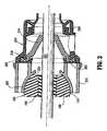
FIGS. 1-2 illustrate a surgical system 10 that is an embodiment of the present invention. Surgical system 10 includesseal assembly 100,cannula assembly 200 andsurgical instrument 300.Seal assembly 100 hasseal element 102 with aninner portion 104 and anouter portion 106.Inner portion 104 forms a seal and definesaperture 108 which is adapted to receivesurgical instrument 300. In one preferred embodiment,inner portion 104 is fabricated from a resilient material whereby portions of theinner portion 104adjacent aperture 108 engagesurgical instrument 300 in fluid tight relation. Suitable materials forinner portion 104 include elastomeric materials such as, e.g., polyisoprene, silicone, rubber, urethane, soft urethane gel, silicon gel, etc. Preferably, the selected material has compressible characteristics to permitinner portion 104 to conform and form a substantial seal about the outer surface of theinstrument 300 during manipulation about the operative site. Theinner portion 104 and/orouter portion 106 may comprise a compressible foam. It is further envisioned thatinner portion 104,outer portion 106 or both, may be a bladder or balloon filled with fluids such as water, saline, gel, etc. Outer portion 106 includes a magnetic material or a ferromagnetic metal. In another embodiment,outer portion 106 may be coated with a magnetic coating or a coating of a ferromagnetic material. The use of magnetic material and/or ferromagnetic material facilitates the establishment of a magnetic coupling to assist in removably retainingseal assembly 100 withincannula assembly 200. The magnetic coupling will be discussed in greater detail hereinbelow.Outer portion 106 may be fabricated from an elastomeric material and be monolithically formed withinner portion 104.Inner portion 104 andouter portion 106 may be fabricated from the same or different material. In certain embodiments,inner portion 104 is formed from an elastomeric material whereasouter portion 106 is formed from a relatively rigid polymeric material.- In the embodiment shown in
FIG 2 ,outer portion 106 is generally spherical and has a cylindrical opening 103 in whichinner portion 104 is disposed.Inner portion 104 has a generally cylindricalshape forming aperture 108 for receipt ofsurgical instrument 300.Outer portion 106 andinner portion 104 may have other shapes, such as elliptical, polygonal, partially truncated sphere or elliptoid, etc. The spherical shape facilitates removable coupling ofseal assembly 100 withcannula assembly 200. It is also envisioned thatseal element 102 may be a partial or truncated sphere as shown inFIG 3 . - With continued reference to
FIGS. 1-2 ,outer portion 106 has anouter surface 110 which is arcuate. As to be appreciated, the arcuate configuration ofouter surface 110 ofseal element 102 permits theseal element 102 to angulate withincannula assembly 200. Seal assembly 100 is preferably mountable aboutsurgical instrument 300 preferably, aboutelongated shaft 302 of the instrument, with theelongated shaft 302 being received withinaperture 108 ofseal element 202. Such mounting is preferably performed prior topositioning seal assembly 100 withincannula assembly 200. Onceseal assembly 100 and theinstrument 300 are positioned withincannula assembly 200,seal element 102 forms a substantial fluid tight seal within the internal structure ofcannula assembly 200 to prevent or substantially minimize the passage of fluids through the cannula assembly.- Referring still to
FIGS. 1-2 ,cannula assembly 200 of the surgical system 10 will be described.Cannula assembly 200 is intended to access a body cavity and permit introduction of instruments required to perform the desired surgical procedure at a remote tissue site.Cannula assembly 200 is particularly adapted for use in laparoscopic surgery where the peritoneal cavity is insufflated with a suitable gas, e.g., CO2, to raise the cavity wall from the internal organs therein.Cannula assembly 200 is typically used with a trocar obturator (not shown) which is a sharp pointed instrument positionable within the passageway of thecannula assembly 200. The trocar obturator is utilized to penetrate the abdominal wall and is then subsequently removed from thecannula assembly 200 to permit introduction of the surgical instrumentation utilized to perform the procedure. In the alternative, a blunt obturator may be used, such as, for example, in a Hasson technique. Semi blunt or dilating obturators may also be used to gain access to the abdominal cavity. Cannula assembly 200 includescannula sleeve 202 andcannula housing 204 mounted to a proximal end of thesleeve 202.Cannula sleeve 202 defines a longitudinal axis "a" extending along the length ofsleeve 202.Sleeve 202 further defines an internallongitudinal passage 206 dimensioned to permit passage of surgical instrumentation.Sleeve 202 may be formed of stainless steel or other rigid materials, including polymeric materials that are medical grade material, such as surgical steel, titanium, polycarbonate, etc.Sleeve 202 may be clear or opaque. The diameter ofsleeve 202 may vary, but, typically ranges from 10 to 15 mm for use with theseal assembly 100 of the present invention.- In one preferred embodiment,
cannula housing 204 includes two components, specifically,main housing 208 which is attached to the proximal end ofcannula sleeve 202 and sealhousing 210.Seal housing 210 may be connectable tomain housing 208 through a bayonet coupling, a snap fit coupling, ultrasonic welding or any other means envisioned by one skilled in the art including, e.g., adhesive means. Alternatively, sealhousing 210 andmain housing 208 may be formed integrally with one another.Main housing 208 further includes diametrically opposed housing grips 212 (FIG 1 ) dimensioned and arranged for gripping engagement by the fingers of the user. Although shown and described as two components,cannula housing 204 may be a single component and attached tocannula sleeve 202 by any of the aforementioned means or may incorporate multiple components. - With reference to
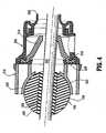
FIG 3 , in conjunction withFIGS. 1-2 ,main housing 208 further includes duck bill or zeroclosure valve 214 which tapers distally and inwardly to a sealed configuration as shown.Valve 214 opens to permit passage of thesurgical instrument 300 and closes in the absence of the instrumentation and/or in response to the pressurized gases communicating from the insufflated body cavity. Other zero closure valves are also contemplated including single or multiple slit valve arrangements, trumpet valves, flapper valves, etc.Valve 214 may be secured withinmain housing 208 by any conventional means. In one embodiment,main housing 208 includes internalcircumferential recess 216 which receives the outerperipheral flange 218 ofvalve 214. Avalve mount 220 may be positioned to secure the flange area ofvalve 214 withinmain housing 208. Seal housing 210 has a substantially cylindrical configuration as shown.Seal housing 210 includesseal mount 222 disposed within the interior of theseal housing 210 concentrically arranged about longitudinal axis "a".Seal mount 222 is adapted to supportseal assembly 100 in the assembled condition of the components.Seal mount 222 hasarcuate support surface 224 defining a concavity as shown.Support surface 224 engagesouter surface 110 ofseal element 102. In a preferred embodiment, the configuration ofarcuate support surface 224 corresponds to the configuration ofouter surface 110 ofseal element 102. For example, in one preferred embodiment, the radius of curvature of each ofarcuate support surface 224 andouter surface 110 ofseal element 102 are substantially equivalent. In this regard,seal element 102 is free to swivel or angulate relative to sealmount 220. The term "angulate" is to be interpreted to include at least two types of movement, namely, rotation ofseal element 102 about longitudinal axis "b" and pivotal movement of theseal element 102 about a pivot axis "p".FIG 4 illustrates angulation ofseal element 102 during manipulation ofsurgical instrument 300.Seal mount 222 preferably is formed of a rigid material such as a metal or polymeric material.Seal mount 222 may have a lubricious coating to facilitate angulation ofseal element 102. Similarly,outer surface 110 ofseal element 102 may have a lubricious coating. Alternatively,seal mount 222 may have an elastomeric layer definingarcuate support surface 224. Irrespective of the materials utilized, positioning ofseal element 102 withinseal mount 222 establishes a fluid-tight relation between theseal element 102 andsupport surface 224, which substantially minimizes passage of gases throughcannula assembly 200 during use in a laparoscopic procedure. In one preferred embodiment,seal mount 222 includes a magnetic material or a ferromagnetic material and cooperates with corresponding magnetic or ferromagnetic material atouter surface 110 ofseal element 102. In this manner, positioning ofseal element 102 withinseal mount 222 establishes a magnetic coupling which functions to retain theseal element 102 within theseal mount 222. Preferably, the strength of the magnetic coupling is selectively controlled to permitseal assembly 100 to angulate withinseal mount 222 while maintaining the mounted condition of theseal assembly 100 relative tocannula assembly 200. The strength of the magnetic coupling should be selected to allow convenient removal ofseal assembly 100 fromseal mount 222 while retaining theseal assembly 100 during manipulation. In any of the above, lubricating coatings may be used to further seal thecannula seal housing 210 and facilitate manipulation of instrument.- Surgical system 10 may be part of a surgical kit incorporating at least one
seal assembly 100,corresponding cannula assembly 200 and/orsurgical instrument 300. For example, the kit could be packaged incorporating aseal assembly 100 andcorresponding cannula assembly 200. A plurality ofseal assemblies 100 of different sizes (e.g., seal apertures with different diameters) for various instrumentation could be incorporated in the kit. Alternatively, the kit could includesurgical instrument 300 and sealassembly 100 with theseal assembly 200 mounted about thesurgical instrument 300, either through a permanent or detachable connection. - Referring now to
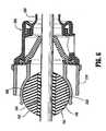
FIGS. 5-6 , there is illustrated another embodiment of the present invention. This embodiment of surgical system incorporatesseal assembly 100 as described hereinabove.Cannula housing 204 includesresilient coupling 226 incorporating first and secondresilient legs 228 which receive and mountseal assembly 100 withincannula 200.Resilient legs 228 are adapted to flex or pivot outwardly in the direction of directional arrows "p" to receiveseal assembly 100 and then return under the influence of their natural resiliency to retainseal assembly 100 withinresilient coupling 226.Resilient legs 228 each include a central arcuate portion 230 defining an arcuate configuration approximating the general arcuate shape of theouter surface 110 ofseal element 102. In the mounted condition ofseal assembly 100, theseal assembly 100 may angulate withincannula assembly 200 in the manner described in connection with the embodiment ofFIGS. 1-4 . The contacting surfaces ofresilient legs 228 andseal element 102 may incorporate lubricious coatings to facilitate rotational and pivotal movement of theseal assembly 100.Resilient legs 228 may comprise a polymeric material or resilient metal such as spring steel. In other regards,seal assembly 100 is utilized in the aforedescribed manner.
Claims (10)
- A surgical system (10), which comprises:a cannula (200) including a cannula housing (204) and a cannula sleeve (202) extending from the cannula housing (204), the cannula defining a longitudinal passage (206) extending between the cannula housing and the cannula sleeve, the cannula sleeve adapted to access an underlying body cavity insufflated with gases, anda seal element (102) at least partially positionable within the cannula housing, the seal element including an aperture (108) adapted for sealed reception of a surgical instrument (300),characterized by:magnetic coupling means for facilitating retention of the seal element within the cannula housing.
- The surgical system according to claim 1, wherein the seal element is adapted to angulate relative to the cannula housing in response to angulation of the surgical instrument.
- The surgical system according to claim 1 or 2, wherein the cannula housing defines an inner surface (224) adjacent the longitudinal passage and the seal element includes an outer surface (110) whereby, upon at least partial positioning of the seal element within the cannula housing, the outer surface of the seal element engages the inner surface of the cannula housing in substantial sealed relation therewith.
- The surgical system according to claim 3, wherein the seal element outer surface has a portion (106) that is arcuate and the cannula housing includes a seal mount (222) having an arcuate support surface (224) for engaging the outer surface arcuate portion of the seal element.
- The surgical system according to claim 4, further including a lubricating coating on either the arcuate outer surface portion of the seal element or the arcuate support surface of the seal mount to facilitate the formation of the substantial seal when the seal element is engaged with the cannula housing.
- The surgical system according to any of the preceding claims, wherein the aperture of the seal element receives the surgical instrument in substantial sealed relation therewith.
- The surgical system according to any of the preceding claims, wherein the cannula housing includes a resilient coupling (226) facilitating the selective retention of the seal element within the cannula housing.
- The surgical system according to any of the preceding claims, wherein the seal element includes a generally spherical portion.
- The surgical system according to any of the preceding claims, wherein the cannula includes a valve (214) adapted to close in the absence of an instrument within the longitudinal passage.
- The surgical system according to any of the preceding claims, wherein one of the seal element and the cannula housing includes a magnetic element and wherein the other of the seal element and the cannula housing includes a ferromagnetic material, the magnetic element and the ferromagnetic material constituting the magnetic coupling means and cooperating to facilitate the removable coupling of the seal element and the cannula housing.
Priority Applications (2)
| Application Number | Priority Date | Filing Date | Title |
|---|---|---|---|
| EP10185427.1AEP2269525B1 (en) | 2005-03-28 | 2006-03-14 | Cannula seal assembly |
| EP09175562.9AEP2160987B1 (en) | 2005-03-28 | 2006-03-14 | Cannula seal assembly |
Applications Claiming Priority (1)
| Application Number | Priority Date | Filing Date | Title |
|---|---|---|---|
| US11/091,165US7582071B2 (en) | 2005-03-28 | 2005-03-28 | Introducer seal assembly |
Related Child Applications (1)
| Application Number | Title | Priority Date | Filing Date |
|---|---|---|---|
| EP10185427.1ADivisionEP2269525B1 (en) | 2005-03-28 | 2006-03-14 | Cannula seal assembly |
Publications (2)
| Publication Number | Publication Date |
|---|---|
| EP1707133A1 EP1707133A1 (en) | 2006-10-04 |
| EP1707133B1true EP1707133B1 (en) | 2009-11-11 |
Family
ID=36600958
Family Applications (3)
| Application Number | Title | Priority Date | Filing Date |
|---|---|---|---|
| EP10185427.1ANot-in-forceEP2269525B1 (en) | 2005-03-28 | 2006-03-14 | Cannula seal assembly |
| EP09175562.9ANot-in-forceEP2160987B1 (en) | 2005-03-28 | 2006-03-14 | Cannula seal assembly |
| EP06005183ANot-in-forceEP1707133B1 (en) | 2005-03-28 | 2006-03-14 | Cannula seal assembly |
Family Applications Before (2)
| Application Number | Title | Priority Date | Filing Date |
|---|---|---|---|
| EP10185427.1ANot-in-forceEP2269525B1 (en) | 2005-03-28 | 2006-03-14 | Cannula seal assembly |
| EP09175562.9ANot-in-forceEP2160987B1 (en) | 2005-03-28 | 2006-03-14 | Cannula seal assembly |
Country Status (7)
| Country | Link |
|---|---|
| US (3) | US7582071B2 (en) |
| EP (3) | EP2269525B1 (en) |
| JP (3) | JP5086549B2 (en) |
| AU (2) | AU2006200781B2 (en) |
| CA (1) | CA2540910C (en) |
| DE (1) | DE602006010260D1 (en) |
| ES (1) | ES2335601T3 (en) |
Cited By (10)
| Publication number | Priority date | Publication date | Assignee | Title |
|---|---|---|---|---|
| US7976501B2 (en) | 2007-12-07 | 2011-07-12 | Ethicon Endo-Surgery, Inc. | Trocar seal with reduced contact area |
| US7981092B2 (en) | 2008-05-08 | 2011-07-19 | Ethicon Endo-Surgery, Inc. | Vibratory trocar |
| US8100929B2 (en) | 2007-06-29 | 2012-01-24 | Ethicon Endo-Surgery, Inc. | Duckbill seal with fluid drainage feature |
| US8206357B2 (en) | 2009-03-26 | 2012-06-26 | Tyco Healthcare Group Lp | Articulating surgical portal apparatus with spring |
| US8273060B2 (en) | 2008-04-28 | 2012-09-25 | Ethicon Endo-Surgery, Inc. | Fluid removal in a surgical access device |
| US8579807B2 (en) | 2008-04-28 | 2013-11-12 | Ethicon Endo-Surgery, Inc. | Absorbing fluids in a surgical access device |
| US8690831B2 (en) | 2008-04-25 | 2014-04-08 | Ethicon Endo-Surgery, Inc. | Gas jet fluid removal in a trocar |
| US8870747B2 (en) | 2008-04-28 | 2014-10-28 | Ethicon Endo-Surgery, Inc. | Scraping fluid removal in a surgical access device |
| US8968249B2 (en) | 2002-05-10 | 2015-03-03 | Covidien Lp | Introducer seal assembly |
| US9358041B2 (en) | 2008-04-28 | 2016-06-07 | Ethicon Endo-Surgery, Llc | Wicking fluid management in a surgical access device |
Families Citing this family (40)
| Publication number | Priority date | Publication date | Assignee | Title |
|---|---|---|---|---|
| US6942671B1 (en) | 2000-11-06 | 2005-09-13 | Tyco Healthcare Group Lp | Surgical sealing apparatus |
| JP4460576B2 (en)* | 2003-04-25 | 2010-05-12 | タイコ ヘルスケア グループ リミテッド パートナーシップ | Surgical hand access device |
| US8663170B2 (en)* | 2003-05-29 | 2014-03-04 | Covidien Lp | Rotating valve assembly including multi-lumen spherical valve |
| WO2005097234A2 (en) | 2004-04-05 | 2005-10-20 | Tyco Healthcare Group Lp | Surgical hand access apparatus |
| US7582071B2 (en)* | 2005-03-28 | 2009-09-01 | Tyco Healthcare Group Lp | Introducer seal assembly |
| US7931624B2 (en) | 2005-04-05 | 2011-04-26 | Tyco Healthcare Group Lp | Introducer seal assembly with low profile gimbal seal |
| US8500631B2 (en)* | 2006-03-27 | 2013-08-06 | Ethicon Endo-Surgery, Inc. | Methods and devices for percutaneous illumination |
| CA2916746C (en)* | 2006-10-17 | 2018-11-27 | C.R. Bard, Inc. | Waste management system |
| CA2672621A1 (en)* | 2007-01-03 | 2008-07-17 | Tyco Healthcare Group, Lp | Surgical system having a magnetic entry |
| US20080171988A1 (en)* | 2007-01-17 | 2008-07-17 | Erblan Surgical, Inc. | Double-cone sphincter introducer assembly and integrated valve assembly |
| CA2632369A1 (en) | 2007-05-31 | 2008-11-30 | Tyco Healthcare Group Lp | Access apparatus with shallow zero closure valve |
| US7918826B2 (en)* | 2007-09-14 | 2011-04-05 | Ethicon Endo-Surgery, Inc. | Trocar assembly |
| US7918827B2 (en)* | 2007-09-25 | 2011-04-05 | Tyco Healthcare Group Lp | Seal assembly for surgical access device |
| US8118783B2 (en)* | 2008-01-30 | 2012-02-21 | Tyco Healthcare Group Lp | Access assembly with spherical valve |
| US8092430B2 (en) | 2008-03-03 | 2012-01-10 | Tyco Healthcare Group Lp | Single port device with multi-lumen cap |
| US8568362B2 (en) | 2008-04-28 | 2013-10-29 | Ethicon Endo-Surgery, Inc. | Surgical access device with sorbents |
| USD700326S1 (en) | 2008-04-28 | 2014-02-25 | Ethicon Endo-Surgery, Inc. | Trocar housing |
| US11235111B2 (en) | 2008-04-28 | 2022-02-01 | Ethicon Llc | Surgical access device |
| US8636686B2 (en) | 2008-04-28 | 2014-01-28 | Ethicon Endo-Surgery, Inc. | Surgical access device |
| US9028448B2 (en) | 2008-06-19 | 2015-05-12 | Covidien Lp | Access seal with interstitial channels |
| US8012129B2 (en)* | 2008-06-25 | 2011-09-06 | Tyco Healthcare Group Lp | Surgical portal apparatus with waffle seal |
| US7896845B2 (en)* | 2008-06-26 | 2011-03-01 | Tyco Healthcare Group Lp | Surgical portal assembly |
| US8025640B2 (en) | 2008-06-27 | 2011-09-27 | Tyco Healthcare Group Lp | Pressurized surgical valve |
| DE102008045692A1 (en)* | 2008-09-04 | 2010-03-11 | Pobitschka, Walter, Dr. | Apparatus and method for providing access to a hollow organ, tool |
| US8430812B2 (en) | 2009-10-05 | 2013-04-30 | Covidien Lp | Surgical access assembly |
| DE102010008922A1 (en)* | 2010-02-23 | 2011-08-25 | Schölly Fiberoptic GmbH, 79211 | Device for observing and / or manipulating objects arranged in a cavity accessible through a narrow opening |
| US8562520B2 (en) | 2010-10-01 | 2013-10-22 | Covidien Lp | Access port |
| US9226735B2 (en) | 2011-05-19 | 2016-01-05 | DePuy Synthes Products, Inc. | Articulating cranial bolt |
| USD671204S1 (en)* | 2012-02-14 | 2012-11-20 | Steffes Corporation | Flare stack burner assembly |
| US9486242B2 (en) | 2012-05-15 | 2016-11-08 | Covidien Lp | Surgical access device including gimbal seal with self-centering mechanism |
| US10299778B2 (en) | 2012-05-15 | 2019-05-28 | Covidien Lp | Surgical access device including gimbal mount cooperating with bellows |
| US9364236B2 (en) | 2012-11-09 | 2016-06-14 | Covidien Lp | Slanted introducer for end-to-end anastomosis anvil |
| US9901372B2 (en) | 2013-02-21 | 2018-02-27 | Covidien Lp | Surgical access device including gimbal mount cooperating with bellows attached to proximal wall of seal housing |
| EP3179946B1 (en)* | 2014-08-13 | 2020-07-08 | Teleflex Medical Incorporated | Surgical instrument electrodes |
| CN111166438A (en)* | 2016-03-29 | 2020-05-19 | 美敦力公司 | A skin surface indwelling device for guiding puncture |
| EP3412229A1 (en)* | 2017-06-07 | 2018-12-12 | Servizo Galego de Saúde (SERGAS) | Surgery multichannel device |
| US12239292B2 (en)* | 2019-01-10 | 2025-03-04 | Atricure, Inc. | Clip application system and method |
| US11357542B2 (en) | 2019-06-21 | 2022-06-14 | Covidien Lp | Valve assembly and retainer for surgical access assembly |
| WO2021136585A1 (en)* | 2019-12-30 | 2021-07-08 | Syntach Ag | An access device for a heart, a removable hemostatic valve unit, and a system and a method of creating a transapical passage on a beating heart |
| JP7730497B2 (en)* | 2021-02-05 | 2025-08-28 | 株式会社Yyp | Endoscopic Devices |
Family Cites Families (46)
| Publication number | Priority date | Publication date | Assignee | Title |
|---|---|---|---|---|
| US4874378A (en)* | 1988-06-01 | 1989-10-17 | Cordis Corporation | Catheter sheath introducer |
| US5389080A (en)* | 1990-07-26 | 1995-02-14 | Yoon; Inbae | Endoscopic portal for use in endoscopic procedures and methods therefor |
| US5478318A (en)* | 1990-07-26 | 1995-12-26 | Yoon; Inbae | Multiluminal endoscopic portal |
| US5395342A (en)* | 1990-07-26 | 1995-03-07 | Yoon; Inbae | Endoscopic portal |
| US5429609A (en)* | 1990-07-26 | 1995-07-04 | Yoon; Inbae | Endoscopic portal for use in endoscopic procedures and methods therefor |
| DE59207776D1 (en)* | 1991-10-31 | 1997-02-06 | Helmut Laser | LOCKING SYSTEM FOR AN INSTRUMENT PASSAGE |
| US5658272A (en)* | 1992-09-15 | 1997-08-19 | Hasson; Harrith M. | Surgical instrument support and method of using the same |
| US6716232B1 (en) | 1993-04-30 | 2004-04-06 | United States Surgical Corporation | Surgical instrument having an articulated jaw structure and a detachable knife |
| US5657963A (en)* | 1993-06-16 | 1997-08-19 | United States Surgical Corporation | Seal assembly for accommodating introduction of surgical instruments |
| CA2126150C (en)* | 1993-07-14 | 2005-02-22 | David T. Green | Seal assembly for accommodating introduction of surgical instruments |
| FR2709945B1 (en)* | 1993-09-15 | 1995-10-27 | Cuilleron J | Trocar for the introduction of endoscopy instruments into cavities. |
| US5554100A (en) | 1994-03-24 | 1996-09-10 | United States Surgical Corporation | Arthroscope with shim for angularly orienting illumination fibers |
| US5569205A (en)* | 1994-07-14 | 1996-10-29 | Hart; Charles C. | Multiport trocar |
| US6162196A (en)* | 1994-07-14 | 2000-12-19 | Applied Medical Resources Corporation | Multiport access device |
| CA2156027C (en) | 1994-10-04 | 2006-07-18 | Keith Ratcliff | Surgical retractor |
| US5938668A (en) | 1994-10-07 | 1999-08-17 | United States Surgical | Surgical suturing apparatus |
| US5613954A (en) | 1994-11-21 | 1997-03-25 | Stryker Corporation | Laparoscopic surgical Y-tube cannula |
| US5820600A (en)* | 1996-05-14 | 1998-10-13 | Innerdyne, Inc. | Adjustable introducer valve |
| US5913870A (en) | 1996-08-13 | 1999-06-22 | United States Surgical Corporation | Surgical dissector |
| US5865817A (en)* | 1997-04-29 | 1999-02-02 | Moenning; Stephen P. | Apparatus and method for securing a medical instrument to a cannula of a trocar assembly |
| ES2333616T3 (en)* | 1997-05-02 | 2010-02-24 | Tyco Healthcare Group Lp | CANULA ASSEMBLY |
| US6231565B1 (en) | 1997-06-18 | 2001-05-15 | United States Surgical Corporation | Robotic arm DLUs for performing surgical tasks |
| US5924976A (en)* | 1997-08-21 | 1999-07-20 | Stelzer; Paul | Minimally invasive surgery device |
| US6036711A (en)* | 1998-02-18 | 2000-03-14 | United States Surgical Corporation | Reusable cannula |
| US5989224A (en)* | 1998-02-23 | 1999-11-23 | Dexide Corporation | Universal seal for use with endoscopic cannula |
| JP2000000246A (en)* | 1998-06-16 | 2000-01-07 | Olympus Optical Co Ltd | Trocar |
| US6228098B1 (en) | 1998-07-10 | 2001-05-08 | General Surgical Innovations, Inc. | Apparatus and method for surgical fastening |
| US6086603A (en)* | 1998-12-14 | 2000-07-11 | Syntheon, Llc | Luminal port device having internal and external sealing mechanisms |
| US6258065B1 (en)* | 1999-03-26 | 2001-07-10 | Core Dynamics, Inc. | Surgical instrument seal assembly |
| US20060020281A1 (en)* | 2000-10-13 | 2006-01-26 | Smith Robert C | Valve assembly including diameter reduction structure for trocar |
| US6942671B1 (en)* | 2000-11-06 | 2005-09-13 | Tyco Healthcare Group Lp | Surgical sealing apparatus |
| US6537290B2 (en)* | 2001-03-05 | 2003-03-25 | Edwards Lifesciences Corporation | Sealing access cannula system |
| WO2003043683A1 (en)* | 2001-11-13 | 2003-05-30 | Applied Medical Resources Corporation | Multi-seal trocar system |
| US7235062B2 (en)* | 2002-01-24 | 2007-06-26 | Applied Medical Resources Corporation | Surgical access device with floating gel seal |
| DE60330661D1 (en)* | 2002-05-10 | 2010-02-04 | Tyco Healthcare | EINFÜHRDICHTUNGSANORDNUNG |
| US7632250B2 (en)* | 2002-05-10 | 2009-12-15 | Tyco Healthcare Group Lp | Introducer seal assembly |
| US20040066008A1 (en)* | 2002-10-04 | 2004-04-08 | Smith Robert C. | Introducer seal assembly |
| US7083626B2 (en)* | 2002-10-04 | 2006-08-01 | Applied Medical Resources Corporation | Surgical access device with pendent valve |
| US7165568B2 (en)* | 2003-05-29 | 2007-01-23 | Axial Technologies Limited | Rotating valve assembly |
| JP2007506527A (en)* | 2003-09-24 | 2007-03-22 | アプライド メディカル リソーシーズ コーポレイション | Anti-inversion trocar seal |
| US20050096695A1 (en)* | 2003-11-03 | 2005-05-05 | Olich Jack M. | Flexible foam seal assembly |
| US7186265B2 (en)* | 2003-12-10 | 2007-03-06 | Medtronic, Inc. | Prosthetic cardiac valves and systems and methods for implanting thereof |
| US7582071B2 (en) | 2005-03-28 | 2009-09-01 | Tyco Healthcare Group Lp | Introducer seal assembly |
| US7931624B2 (en)* | 2005-04-05 | 2011-04-26 | Tyco Healthcare Group Lp | Introducer seal assembly with low profile gimbal seal |
| US7762990B2 (en)* | 2007-05-24 | 2010-07-27 | Tyco Healthcare Group Lp | Surgical access apparatus with centering mechanism |
| JP4825734B2 (en)* | 2007-06-15 | 2011-11-30 | 株式会社日立ハイテクノロジーズ | Calibration method and system between different types of measuring devices |
- 2005
- 2005-03-28USUS11/091,165patent/US7582071B2/ennot_activeExpired - Fee Related
- 2006
- 2006-02-24AUAU2006200781Apatent/AU2006200781B2/ennot_activeCeased
- 2006-03-09JPJP2006064946Apatent/JP5086549B2/ennot_activeExpired - Fee Related
- 2006-03-14EPEP10185427.1Apatent/EP2269525B1/ennot_activeNot-in-force
- 2006-03-14EPEP09175562.9Apatent/EP2160987B1/ennot_activeNot-in-force
- 2006-03-14DEDE602006010260Tpatent/DE602006010260D1/enactiveActive
- 2006-03-14ESES06005183Tpatent/ES2335601T3/enactiveActive
- 2006-03-14EPEP06005183Apatent/EP1707133B1/ennot_activeNot-in-force
- 2006-03-23CACA2540910Apatent/CA2540910C/ennot_activeExpired - Fee Related
- 2009
- 2009-08-05USUS12/535,955patent/US7896847B2/ennot_activeExpired - Fee Related
- 2011
- 2011-01-31USUS13/017,295patent/US8235947B2/ennot_activeExpired - Fee Related
- 2011-02-21AUAU2011200729Apatent/AU2011200729B2/ennot_activeCeased
- 2011-07-21JPJP2011160349Apatent/JP2011235144A/enactivePending
- 2012
- 2012-03-13JPJP2012055622Apatent/JP5355734B2/ennot_activeExpired - Fee Related
Cited By (10)
| Publication number | Priority date | Publication date | Assignee | Title |
|---|---|---|---|---|
| US8968249B2 (en) | 2002-05-10 | 2015-03-03 | Covidien Lp | Introducer seal assembly |
| US8100929B2 (en) | 2007-06-29 | 2012-01-24 | Ethicon Endo-Surgery, Inc. | Duckbill seal with fluid drainage feature |
| US7976501B2 (en) | 2007-12-07 | 2011-07-12 | Ethicon Endo-Surgery, Inc. | Trocar seal with reduced contact area |
| US8690831B2 (en) | 2008-04-25 | 2014-04-08 | Ethicon Endo-Surgery, Inc. | Gas jet fluid removal in a trocar |
| US8273060B2 (en) | 2008-04-28 | 2012-09-25 | Ethicon Endo-Surgery, Inc. | Fluid removal in a surgical access device |
| US8579807B2 (en) | 2008-04-28 | 2013-11-12 | Ethicon Endo-Surgery, Inc. | Absorbing fluids in a surgical access device |
| US8870747B2 (en) | 2008-04-28 | 2014-10-28 | Ethicon Endo-Surgery, Inc. | Scraping fluid removal in a surgical access device |
| US9358041B2 (en) | 2008-04-28 | 2016-06-07 | Ethicon Endo-Surgery, Llc | Wicking fluid management in a surgical access device |
| US7981092B2 (en) | 2008-05-08 | 2011-07-19 | Ethicon Endo-Surgery, Inc. | Vibratory trocar |
| US8206357B2 (en) | 2009-03-26 | 2012-06-26 | Tyco Healthcare Group Lp | Articulating surgical portal apparatus with spring |
Also Published As
| Publication number | Publication date |
|---|---|
| AU2011200729A1 (en) | 2011-03-10 |
| EP2160987B1 (en) | 2013-12-25 |
| JP5355734B2 (en) | 2013-11-27 |
| JP2006271965A (en) | 2006-10-12 |
| AU2006200781B2 (en) | 2010-11-25 |
| EP2269525A2 (en) | 2011-01-05 |
| US20110124972A1 (en) | 2011-05-26 |
| EP2160987A1 (en) | 2010-03-10 |
| JP5086549B2 (en) | 2012-11-28 |
| EP2269525B1 (en) | 2016-11-02 |
| US8235947B2 (en) | 2012-08-07 |
| ES2335601T3 (en) | 2010-03-30 |
| US7896847B2 (en) | 2011-03-01 |
| JP2011235144A (en) | 2011-11-24 |
| AU2006200781A1 (en) | 2006-10-12 |
| JP2012120883A (en) | 2012-06-28 |
| EP2269525A3 (en) | 2013-08-14 |
| US20090292251A1 (en) | 2009-11-26 |
| DE602006010260D1 (en) | 2009-12-24 |
| EP1707133A1 (en) | 2006-10-04 |
| CA2540910C (en) | 2014-06-10 |
| US20060217666A1 (en) | 2006-09-28 |
| CA2540910A1 (en) | 2006-09-28 |
| US7582071B2 (en) | 2009-09-01 |
| AU2011200729B2 (en) | 2012-02-02 |
Similar Documents
| Publication | Publication Date | Title |
|---|---|---|
| EP1707133B1 (en) | Cannula seal assembly | |
| EP1629787B1 (en) | Gel seal for a surgical trocar apparatus | |
| EP2402048B1 (en) | Introducer assembly with suspended seal | |
| EP1709918B1 (en) | Introducer seal assembly with low profile gimbal seal | |
| EP2087846B1 (en) | Access assembly with spherical valve | |
| AU2008261180B2 (en) | Introducer seal assembly | |
| AU2008229799A1 (en) | Surgical portal kit for use in single incision surgery | |
| EP2165667A1 (en) | Introducer seal assembly | |
| AU2006200888A1 (en) | Introducer seal assembly | |
| AU2008202298A1 (en) | Access apparatus with shallow zero closure valve | |
| EP2036507A1 (en) | Composite seal and method for manufacturing | |
| US20110124971A1 (en) | Portal assembly with multi-seal system | |
| AU2011200662A1 (en) | Portal apparatus with a tubular seal device | |
| AU2011205165A1 (en) | Introducer seal assembly |
Legal Events
| Date | Code | Title | Description |
|---|---|---|---|
| PUAI | Public reference made under article 153(3) epc to a published international application that has entered the european phase | Free format text:ORIGINAL CODE: 0009012 | |
| AK | Designated contracting states | Kind code of ref document:A1 Designated state(s):AT BE BG CH CY CZ DE DK EE ES FI FR GB GR HU IE IS IT LI LT LU LV MC NL PL PT RO SE SI SK TR | |
| AX | Request for extension of the european patent | Extension state:AL BA HR MK YU | |
| 17P | Request for examination filed | Effective date:20070326 | |
| 17Q | First examination report despatched | Effective date:20070502 | |
| AKX | Designation fees paid | Designated state(s):DE ES FR GB IE IT | |
| GRAP | Despatch of communication of intention to grant a patent | Free format text:ORIGINAL CODE: EPIDOSNIGR1 | |
| GRAS | Grant fee paid | Free format text:ORIGINAL CODE: EPIDOSNIGR3 | |
| GRAA | (expected) grant | Free format text:ORIGINAL CODE: 0009210 | |
| AK | Designated contracting states | Kind code of ref document:B1 Designated state(s):DE ES FR GB IE IT | |
| REG | Reference to a national code | Ref country code:GB Ref legal event code:FG4D | |
| REG | Reference to a national code | Ref country code:IE Ref legal event code:FG4D | |
| REF | Corresponds to: | Ref document number:602006010260 Country of ref document:DE Date of ref document:20091224 Kind code of ref document:P | |
| REG | Reference to a national code | Ref country code:ES Ref legal event code:FG2A Ref document number:2335601 Country of ref document:ES Kind code of ref document:T3 | |
| PLBE | No opposition filed within time limit | Free format text:ORIGINAL CODE: 0009261 | |
| STAA | Information on the status of an ep patent application or granted ep patent | Free format text:STATUS: NO OPPOSITION FILED WITHIN TIME LIMIT | |
| 26N | No opposition filed | Effective date:20100812 | |
| PGFP | Annual fee paid to national office [announced via postgrant information from national office to epo] | Ref country code:IT Payment date:20120323 Year of fee payment:7 | |
| PGFP | Annual fee paid to national office [announced via postgrant information from national office to epo] | Ref country code:ES Payment date:20141027 Year of fee payment:9 | |
| PG25 | Lapsed in a contracting state [announced via postgrant information from national office to epo] | Ref country code:IT Free format text:LAPSE BECAUSE OF NON-PAYMENT OF DUE FEES Effective date:20140314 | |
| REG | Reference to a national code | Ref country code:FR Ref legal event code:PLFP Year of fee payment:11 | |
| REG | Reference to a national code | Ref country code:ES Ref legal event code:FD2A Effective date:20160427 | |
| PG25 | Lapsed in a contracting state [announced via postgrant information from national office to epo] | Ref country code:ES Free format text:LAPSE BECAUSE OF NON-PAYMENT OF DUE FEES Effective date:20150315 | |
| REG | Reference to a national code | Ref country code:FR Ref legal event code:PLFP Year of fee payment:12 | |
| PGFP | Annual fee paid to national office [announced via postgrant information from national office to epo] | Ref country code:FR Payment date:20170221 Year of fee payment:12 Ref country code:DE Payment date:20170222 Year of fee payment:12 | |
| PGFP | Annual fee paid to national office [announced via postgrant information from national office to epo] | Ref country code:GB Payment date:20170224 Year of fee payment:12 Ref country code:IE Payment date:20170222 Year of fee payment:12 | |
| REG | Reference to a national code | Ref country code:DE Ref legal event code:R119 Ref document number:602006010260 Country of ref document:DE | |
| GBPC | Gb: european patent ceased through non-payment of renewal fee | Effective date:20180314 | |
| REG | Reference to a national code | Ref country code:IE Ref legal event code:MM4A | |
| PG25 | Lapsed in a contracting state [announced via postgrant information from national office to epo] | Ref country code:DE Free format text:LAPSE BECAUSE OF NON-PAYMENT OF DUE FEES Effective date:20181002 Ref country code:IE Free format text:LAPSE BECAUSE OF NON-PAYMENT OF DUE FEES Effective date:20180314 | |
| PG25 | Lapsed in a contracting state [announced via postgrant information from national office to epo] | Ref country code:GB Free format text:LAPSE BECAUSE OF NON-PAYMENT OF DUE FEES Effective date:20180314 | |
| PG25 | Lapsed in a contracting state [announced via postgrant information from national office to epo] | Ref country code:FR Free format text:LAPSE BECAUSE OF NON-PAYMENT OF DUE FEES Effective date:20180331 |