EP1706272B1 - Inkjet printer unit having a high speed print engine - Google Patents
Inkjet printer unit having a high speed print engineDownload PDFInfo
- Publication number
- EP1706272B1 EP1706272B1EP04802091AEP04802091AEP1706272B1EP 1706272 B1EP1706272 B1EP 1706272B1EP 04802091 AEP04802091 AEP 04802091AEP 04802091 AEP04802091 AEP 04802091AEP 1706272 B1EP1706272 B1EP 1706272B1
- Authority
- EP
- European Patent Office
- Prior art keywords
- ink
- assembly
- printhead
- unit
- media
- Prior art date
- Legal status (The legal status is an assumption and is not a legal conclusion. Google has not performed a legal analysis and makes no representation as to the accuracy of the status listed.)
- Ceased
Links
- 238000007639printingMethods0.000claimsdescription66
- 238000004891communicationMethods0.000claimsdescription18
- 230000007723transport mechanismEffects0.000claims2
- 238000009826distributionMethods0.000abstractdescription56
- 239000000976inkSubstances0.000description530
- 239000010410layerSubstances0.000description86
- 238000003860storageMethods0.000description75
- 238000000465mouldingMethods0.000description72
- 239000000463materialSubstances0.000description61
- 230000002745absorbentEffects0.000description48
- 239000002250absorbentSubstances0.000description48
- 238000000275quality assuranceMethods0.000description48
- 230000037452primingEffects0.000description40
- 239000012530fluidSubstances0.000description27
- 230000009471actionEffects0.000description24
- 238000003032molecular dockingMethods0.000description23
- WAZUWHGJMMZVHH-UHFFFAOYSA-N1,2,3-trichloro-5-(2,6-dichlorophenyl)benzeneChemical compoundClC1=C(Cl)C(Cl)=CC(C=2C(=CC=CC=2Cl)Cl)=C1WAZUWHGJMMZVHH-UHFFFAOYSA-N0.000description22
- 230000033001locomotionEffects0.000description22
- HCWZEPKLWVAEOV-UHFFFAOYSA-N2,2',5,5'-tetrachlorobiphenylChemical compoundClC1=CC=C(Cl)C(C=2C(=CC=C(Cl)C=2)Cl)=C1HCWZEPKLWVAEOV-UHFFFAOYSA-N0.000description19
- 238000000034methodMethods0.000description15
- VYPSYNLAJGMNEJ-UHFFFAOYSA-NSilicium dioxideChemical compoundO=[Si]=OVYPSYNLAJGMNEJ-UHFFFAOYSA-N0.000description12
- 230000004888barrier functionEffects0.000description10
- 230000006835compressionEffects0.000description10
- 238000007906compressionMethods0.000description10
- 230000008569processEffects0.000description10
- XUIMIQQOPSSXEZ-UHFFFAOYSA-NSiliconChemical compound[Si]XUIMIQQOPSSXEZ-UHFFFAOYSA-N0.000description9
- 230000006870functionEffects0.000description9
- 239000011521glassSubstances0.000description9
- 229910052710siliconInorganic materials0.000description9
- 239000010703siliconSubstances0.000description9
- 239000000758substrateSubstances0.000description9
- 238000010438heat treatmentMethods0.000description8
- 230000005499meniscusEffects0.000description8
- 238000007789sealingMethods0.000description8
- 238000012546transferMethods0.000description8
- NRTOMJZYCJJWKI-UHFFFAOYSA-NTitanium nitrideChemical compound[Ti]#NNRTOMJZYCJJWKI-UHFFFAOYSA-N0.000description7
- 239000000872bufferSubstances0.000description7
- 239000003086colorantSubstances0.000description7
- 230000000694effectsEffects0.000description7
- 239000006260foamSubstances0.000description7
- 230000007246mechanismEffects0.000description7
- 229910052751metalInorganic materials0.000description7
- 239000002184metalSubstances0.000description7
- 230000000717retained effectEffects0.000description7
- 235000012239silicon dioxideNutrition0.000description6
- 239000000377silicon dioxideSubstances0.000description6
- 229920000106Liquid crystal polymerPolymers0.000description5
- 239000004977Liquid-crystal polymers (LCPs)Substances0.000description5
- 238000010276constructionMethods0.000description5
- 238000013461designMethods0.000description5
- 238000010304firingMethods0.000description5
- 238000012545processingMethods0.000description5
- 230000002829reductive effectEffects0.000description5
- 238000013022ventingMethods0.000description5
- 239000000853adhesiveSubstances0.000description4
- 230000001070adhesive effectEffects0.000description4
- 239000012790adhesive layerSubstances0.000description4
- 239000000356contaminantSubstances0.000description4
- 239000004033plasticSubstances0.000description4
- 229920003023plasticPolymers0.000description4
- 229910000570CupronickelInorganic materials0.000description3
- 229910000831SteelInorganic materials0.000description3
- 239000002313adhesive filmSubstances0.000description3
- 239000004411aluminiumSubstances0.000description3
- 229910052782aluminiumInorganic materials0.000description3
- XAGFODPZIPBFFR-UHFFFAOYSA-NaluminiumChemical compound[Al]XAGFODPZIPBFFR-UHFFFAOYSA-N0.000description3
- 238000005452bendingMethods0.000description3
- 230000005540biological transmissionEffects0.000description3
- 238000009792diffusion processMethods0.000description3
- 239000013536elastomeric materialSubstances0.000description3
- 238000004519manufacturing processMethods0.000description3
- 239000011148porous materialSubstances0.000description3
- 230000002441reversible effectEffects0.000description3
- HQVNEWCFYHHQES-UHFFFAOYSA-Nsilicon nitrideChemical compoundN12[Si]34N5[Si]62N3[Si]51N64HQVNEWCFYHHQES-UHFFFAOYSA-N0.000description3
- 239000010959steelSubstances0.000description3
- 229910052727yttriumInorganic materials0.000description3
- 229920000089Cyclic olefin copolymerPolymers0.000description2
- 229910052581Si3N4Inorganic materials0.000description2
- 230000004913activationEffects0.000description2
- 229910045601alloyInorganic materials0.000description2
- 239000000956alloySubstances0.000description2
- 238000003491arrayMethods0.000description2
- 230000000712assemblyEffects0.000description2
- 238000000429assemblyMethods0.000description2
- 230000000903blocking effectEffects0.000description2
- 230000003139buffering effectEffects0.000description2
- 238000005229chemical vapour depositionMethods0.000description2
- 239000011248coating agentSubstances0.000description2
- 238000000576coating methodMethods0.000description2
- YOCUPQPZWBBYIX-UHFFFAOYSA-Ncopper nickelChemical compound[Ni].[Cu]YOCUPQPZWBBYIX-UHFFFAOYSA-N0.000description2
- 230000006837decompressionEffects0.000description2
- 230000000881depressing effectEffects0.000description2
- 238000010586diagramMethods0.000description2
- 238000001035dryingMethods0.000description2
- 239000000428dustSubstances0.000description2
- 229920001971elastomerPolymers0.000description2
- 239000000834fixativeSubstances0.000description2
- 238000005286illuminationMethods0.000description2
- 238000005304joiningMethods0.000description2
- 238000002156mixingMethods0.000description2
- 230000004048modificationEffects0.000description2
- 238000012986modificationMethods0.000description2
- 239000002991molded plasticSubstances0.000description2
- 230000036961partial effectEffects0.000description2
- 239000013618particulate matterSubstances0.000description2
- 238000002161passivationMethods0.000description2
- 239000011295pitchSubstances0.000description2
- 229920002492poly(sulfone)Polymers0.000description2
- 239000004417polycarbonateSubstances0.000description2
- 238000003825pressingMethods0.000description2
- 239000005060rubberSubstances0.000description2
- 238000012360testing methodMethods0.000description2
- 238000007669thermal treatmentMethods0.000description2
- 239000004713Cyclic olefin copolymerSubstances0.000description1
- 239000004593EpoxySubstances0.000description1
- JOYRKODLDBILNP-UHFFFAOYSA-NEthyl urethaneChemical compoundCCOC(N)=OJOYRKODLDBILNP-UHFFFAOYSA-N0.000description1
- 239000004793PolystyreneSubstances0.000description1
- 238000010521absorption reactionMethods0.000description1
- NIXOWILDQLNWCW-UHFFFAOYSA-Nacrylic acid groupChemical groupC(C=C)(=O)ONIXOWILDQLNWCW-UHFFFAOYSA-N0.000description1
- 229910021486amorphous silicon dioxideInorganic materials0.000description1
- 238000013459approachMethods0.000description1
- 230000002457bidirectional effectEffects0.000description1
- 230000001413cellular effectEffects0.000description1
- 210000000078clawAnatomy0.000description1
- 239000002131composite materialSubstances0.000description1
- 238000011109contaminationMethods0.000description1
- 230000008602contractionEffects0.000description1
- 238000013270controlled releaseMethods0.000description1
- 230000008878couplingEffects0.000description1
- 238000010168coupling processMethods0.000description1
- 238000005859coupling reactionMethods0.000description1
- 238000002425crystallisationMethods0.000description1
- 238000013500data storageMethods0.000description1
- 230000009849deactivationEffects0.000description1
- 230000001419dependent effectEffects0.000description1
- 230000000994depressogenic effectEffects0.000description1
- 238000006073displacement reactionMethods0.000description1
- 230000009977dual effectEffects0.000description1
- 238000005516engineering processMethods0.000description1
- 238000005530etchingMethods0.000description1
- 229920002313fluoropolymerPolymers0.000description1
- 239000004811fluoropolymerSubstances0.000description1
- 239000006112glass ceramic compositionSubstances0.000description1
- 235000003642hungerNutrition0.000description1
- 230000002209hydrophobic effectEffects0.000description1
- -1hydroxyl ionsChemical class0.000description1
- 238000002347injectionMethods0.000description1
- 239000007924injectionSubstances0.000description1
- 238000003780insertionMethods0.000description1
- 230000037431insertionEffects0.000description1
- 230000003993interactionEffects0.000description1
- 238000002955isolationMethods0.000description1
- 238000003475laminationMethods0.000description1
- 230000000670limiting effectEffects0.000description1
- 239000007788liquidSubstances0.000description1
- 238000012423maintenanceMethods0.000description1
- 230000007257malfunctionEffects0.000description1
- 238000013507mappingMethods0.000description1
- 230000013011matingEffects0.000description1
- 239000011159matrix materialSubstances0.000description1
- 239000012528membraneSubstances0.000description1
- 239000007769metal materialSubstances0.000description1
- 239000002159nanocrystalSubstances0.000description1
- 150000004767nitridesChemical class0.000description1
- 239000000615nonconductorSubstances0.000description1
- 239000011236particulate materialSubstances0.000description1
- 230000000149penetrating effectEffects0.000description1
- 230000035515penetrationEffects0.000description1
- 230000002093peripheral effectEffects0.000description1
- 238000006552photochemical reactionMethods0.000description1
- 229920000515polycarbonatePolymers0.000description1
- 229920006254polymer filmPolymers0.000description1
- 239000002861polymer materialSubstances0.000description1
- 229920002223polystyrenePolymers0.000description1
- 238000007781pre-processingMethods0.000description1
- 230000002265preventionEffects0.000description1
- 230000009467reductionEffects0.000description1
- 238000009877renderingMethods0.000description1
- 230000004044responseEffects0.000description1
- 230000000630rising effectEffects0.000description1
- 229920006395saturated elastomerPolymers0.000description1
- 238000007650screen-printingMethods0.000description1
- 239000007787solidSubstances0.000description1
- 238000000638solvent extractionMethods0.000description1
- 230000007480spreadingEffects0.000description1
- 238000003892spreadingMethods0.000description1
- 230000037351starvationEffects0.000description1
- 230000003068static effectEffects0.000description1
- 229920001169thermoplasticPolymers0.000description1
- 229920001187thermosetting polymerPolymers0.000description1
- 239000004416thermosoftening plasticSubstances0.000description1
- 238000011144upstream manufacturingMethods0.000description1
- 238000012795verificationMethods0.000description1
- 238000003466weldingMethods0.000description1
- 238000009736wettingMethods0.000description1
Images


Classifications
- B—PERFORMING OPERATIONS; TRANSPORTING
- B41—PRINTING; LINING MACHINES; TYPEWRITERS; STAMPS
- B41J—TYPEWRITERS; SELECTIVE PRINTING MECHANISMS, i.e. MECHANISMS PRINTING OTHERWISE THAN FROM A FORME; CORRECTION OF TYPOGRAPHICAL ERRORS
- B41J25/00—Actions or mechanisms not otherwise provided for
- B41J25/34—Bodily-changeable print heads or carriages
- B—PERFORMING OPERATIONS; TRANSPORTING
- B41—PRINTING; LINING MACHINES; TYPEWRITERS; STAMPS
- B41J—TYPEWRITERS; SELECTIVE PRINTING MECHANISMS, i.e. MECHANISMS PRINTING OTHERWISE THAN FROM A FORME; CORRECTION OF TYPOGRAPHICAL ERRORS
- B41J2/00—Typewriters or selective printing mechanisms characterised by the printing or marking process for which they are designed
- B41J2/005—Typewriters or selective printing mechanisms characterised by the printing or marking process for which they are designed characterised by bringing liquid or particles selectively into contact with a printing material
- B41J2/01—Ink jet
- B41J2/015—Ink jet characterised by the jet generation process
- B41J2/04—Ink jet characterised by the jet generation process generating single droplets or particles on demand
- B41J2/045—Ink jet characterised by the jet generation process generating single droplets or particles on demand by pressure, e.g. electromechanical transducers
- B41J2/04501—Control methods or devices therefor, e.g. driver circuits, control circuits
- B41J2/04541—Specific driving circuit
- B—PERFORMING OPERATIONS; TRANSPORTING
- B41—PRINTING; LINING MACHINES; TYPEWRITERS; STAMPS
- B41J—TYPEWRITERS; SELECTIVE PRINTING MECHANISMS, i.e. MECHANISMS PRINTING OTHERWISE THAN FROM A FORME; CORRECTION OF TYPOGRAPHICAL ERRORS
- B41J2/00—Typewriters or selective printing mechanisms characterised by the printing or marking process for which they are designed
- B41J2/005—Typewriters or selective printing mechanisms characterised by the printing or marking process for which they are designed characterised by bringing liquid or particles selectively into contact with a printing material
- B41J2/01—Ink jet
- B41J2/015—Ink jet characterised by the jet generation process
- B41J2/04—Ink jet characterised by the jet generation process generating single droplets or particles on demand
- B41J2/045—Ink jet characterised by the jet generation process generating single droplets or particles on demand by pressure, e.g. electromechanical transducers
- B41J2/04501—Control methods or devices therefor, e.g. driver circuits, control circuits
- B41J2/04543—Block driving
- B—PERFORMING OPERATIONS; TRANSPORTING
- B41—PRINTING; LINING MACHINES; TYPEWRITERS; STAMPS
- B41J—TYPEWRITERS; SELECTIVE PRINTING MECHANISMS, i.e. MECHANISMS PRINTING OTHERWISE THAN FROM A FORME; CORRECTION OF TYPOGRAPHICAL ERRORS
- B41J2/00—Typewriters or selective printing mechanisms characterised by the printing or marking process for which they are designed
- B41J2/005—Typewriters or selective printing mechanisms characterised by the printing or marking process for which they are designed characterised by bringing liquid or particles selectively into contact with a printing material
- B41J2/01—Ink jet
- B41J2/015—Ink jet characterised by the jet generation process
- B41J2/04—Ink jet characterised by the jet generation process generating single droplets or particles on demand
- B41J2/045—Ink jet characterised by the jet generation process generating single droplets or particles on demand by pressure, e.g. electromechanical transducers
- B41J2/04501—Control methods or devices therefor, e.g. driver circuits, control circuits
- B41J2/0458—Control methods or devices therefor, e.g. driver circuits, control circuits controlling heads based on heating elements forming bubbles
- B—PERFORMING OPERATIONS; TRANSPORTING
- B41—PRINTING; LINING MACHINES; TYPEWRITERS; STAMPS
- B41J—TYPEWRITERS; SELECTIVE PRINTING MECHANISMS, i.e. MECHANISMS PRINTING OTHERWISE THAN FROM A FORME; CORRECTION OF TYPOGRAPHICAL ERRORS
- B41J2/00—Typewriters or selective printing mechanisms characterised by the printing or marking process for which they are designed
- B41J2/005—Typewriters or selective printing mechanisms characterised by the printing or marking process for which they are designed characterised by bringing liquid or particles selectively into contact with a printing material
- B41J2/01—Ink jet
- B41J2/015—Ink jet characterised by the jet generation process
- B41J2/04—Ink jet characterised by the jet generation process generating single droplets or particles on demand
- B41J2/045—Ink jet characterised by the jet generation process generating single droplets or particles on demand by pressure, e.g. electromechanical transducers
- B41J2/04501—Control methods or devices therefor, e.g. driver circuits, control circuits
- B41J2/04585—Control methods or devices therefor, e.g. driver circuits, control circuits controlling heads based on thermal bent actuators
- B—PERFORMING OPERATIONS; TRANSPORTING
- B41—PRINTING; LINING MACHINES; TYPEWRITERS; STAMPS
- B41J—TYPEWRITERS; SELECTIVE PRINTING MECHANISMS, i.e. MECHANISMS PRINTING OTHERWISE THAN FROM A FORME; CORRECTION OF TYPOGRAPHICAL ERRORS
- B41J2/00—Typewriters or selective printing mechanisms characterised by the printing or marking process for which they are designed
- B41J2/005—Typewriters or selective printing mechanisms characterised by the printing or marking process for which they are designed characterised by bringing liquid or particles selectively into contact with a printing material
- B41J2/01—Ink jet
- B41J2/015—Ink jet characterised by the jet generation process
- B41J2/04—Ink jet characterised by the jet generation process generating single droplets or particles on demand
- B41J2/045—Ink jet characterised by the jet generation process generating single droplets or particles on demand by pressure, e.g. electromechanical transducers
- B41J2/04501—Control methods or devices therefor, e.g. driver circuits, control circuits
- B41J2/04591—Width of the driving signal being adjusted
- B—PERFORMING OPERATIONS; TRANSPORTING
- B41—PRINTING; LINING MACHINES; TYPEWRITERS; STAMPS
- B41J—TYPEWRITERS; SELECTIVE PRINTING MECHANISMS, i.e. MECHANISMS PRINTING OTHERWISE THAN FROM A FORME; CORRECTION OF TYPOGRAPHICAL ERRORS
- B41J2/00—Typewriters or selective printing mechanisms characterised by the printing or marking process for which they are designed
- B41J2/005—Typewriters or selective printing mechanisms characterised by the printing or marking process for which they are designed characterised by bringing liquid or particles selectively into contact with a printing material
- B41J2/01—Ink jet
- B41J2/135—Nozzles
- B41J2/14—Structure thereof only for on-demand ink jet heads
- B41J2/14016—Structure of bubble jet print heads
- B—PERFORMING OPERATIONS; TRANSPORTING
- B41—PRINTING; LINING MACHINES; TYPEWRITERS; STAMPS
- B41J—TYPEWRITERS; SELECTIVE PRINTING MECHANISMS, i.e. MECHANISMS PRINTING OTHERWISE THAN FROM A FORME; CORRECTION OF TYPOGRAPHICAL ERRORS
- B41J2/00—Typewriters or selective printing mechanisms characterised by the printing or marking process for which they are designed
- B41J2/005—Typewriters or selective printing mechanisms characterised by the printing or marking process for which they are designed characterised by bringing liquid or particles selectively into contact with a printing material
- B41J2/01—Ink jet
- B41J2/135—Nozzles
- B41J2/14—Structure thereof only for on-demand ink jet heads
- B41J2/14427—Structure of ink jet print heads with thermal bend detached actuators
- B—PERFORMING OPERATIONS; TRANSPORTING
- B41—PRINTING; LINING MACHINES; TYPEWRITERS; STAMPS
- B41J—TYPEWRITERS; SELECTIVE PRINTING MECHANISMS, i.e. MECHANISMS PRINTING OTHERWISE THAN FROM A FORME; CORRECTION OF TYPOGRAPHICAL ERRORS
- B41J2/00—Typewriters or selective printing mechanisms characterised by the printing or marking process for which they are designed
- B41J2/005—Typewriters or selective printing mechanisms characterised by the printing or marking process for which they are designed characterised by bringing liquid or particles selectively into contact with a printing material
- B41J2/01—Ink jet
- B41J2/135—Nozzles
- B41J2/145—Arrangement thereof
- B41J2/155—Arrangement thereof for line printing
- B—PERFORMING OPERATIONS; TRANSPORTING
- B41—PRINTING; LINING MACHINES; TYPEWRITERS; STAMPS
- B41J—TYPEWRITERS; SELECTIVE PRINTING MECHANISMS, i.e. MECHANISMS PRINTING OTHERWISE THAN FROM A FORME; CORRECTION OF TYPOGRAPHICAL ERRORS
- B41J2/00—Typewriters or selective printing mechanisms characterised by the printing or marking process for which they are designed
- B41J2/005—Typewriters or selective printing mechanisms characterised by the printing or marking process for which they are designed characterised by bringing liquid or particles selectively into contact with a printing material
- B41J2/01—Ink jet
- B41J2/135—Nozzles
- B41J2/16—Production of nozzles
- B41J2/1621—Manufacturing processes
- B41J2/1623—Manufacturing processes bonding and adhesion
- B—PERFORMING OPERATIONS; TRANSPORTING
- B41—PRINTING; LINING MACHINES; TYPEWRITERS; STAMPS
- B41J—TYPEWRITERS; SELECTIVE PRINTING MECHANISMS, i.e. MECHANISMS PRINTING OTHERWISE THAN FROM A FORME; CORRECTION OF TYPOGRAPHICAL ERRORS
- B41J2/00—Typewriters or selective printing mechanisms characterised by the printing or marking process for which they are designed
- B41J2/005—Typewriters or selective printing mechanisms characterised by the printing or marking process for which they are designed characterised by bringing liquid or particles selectively into contact with a printing material
- B41J2/01—Ink jet
- B41J2/135—Nozzles
- B41J2/16—Production of nozzles
- B41J2/1621—Manufacturing processes
- B41J2/1626—Manufacturing processes etching
- B41J2/1628—Manufacturing processes etching dry etching
- B—PERFORMING OPERATIONS; TRANSPORTING
- B41—PRINTING; LINING MACHINES; TYPEWRITERS; STAMPS
- B41J—TYPEWRITERS; SELECTIVE PRINTING MECHANISMS, i.e. MECHANISMS PRINTING OTHERWISE THAN FROM A FORME; CORRECTION OF TYPOGRAPHICAL ERRORS
- B41J2/00—Typewriters or selective printing mechanisms characterised by the printing or marking process for which they are designed
- B41J2/005—Typewriters or selective printing mechanisms characterised by the printing or marking process for which they are designed characterised by bringing liquid or particles selectively into contact with a printing material
- B41J2/01—Ink jet
- B41J2/135—Nozzles
- B41J2/16—Production of nozzles
- B41J2/1621—Manufacturing processes
- B41J2/1632—Manufacturing processes machining
- B41J2/1634—Manufacturing processes machining laser machining
- B—PERFORMING OPERATIONS; TRANSPORTING
- B41—PRINTING; LINING MACHINES; TYPEWRITERS; STAMPS
- B41J—TYPEWRITERS; SELECTIVE PRINTING MECHANISMS, i.e. MECHANISMS PRINTING OTHERWISE THAN FROM A FORME; CORRECTION OF TYPOGRAPHICAL ERRORS
- B41J2/00—Typewriters or selective printing mechanisms characterised by the printing or marking process for which they are designed
- B41J2/005—Typewriters or selective printing mechanisms characterised by the printing or marking process for which they are designed characterised by bringing liquid or particles selectively into contact with a printing material
- B41J2/01—Ink jet
- B41J2/135—Nozzles
- B41J2/16—Production of nozzles
- B41J2/1621—Manufacturing processes
- B41J2/1637—Manufacturing processes molding
- B—PERFORMING OPERATIONS; TRANSPORTING
- B41—PRINTING; LINING MACHINES; TYPEWRITERS; STAMPS
- B41J—TYPEWRITERS; SELECTIVE PRINTING MECHANISMS, i.e. MECHANISMS PRINTING OTHERWISE THAN FROM A FORME; CORRECTION OF TYPOGRAPHICAL ERRORS
- B41J2/00—Typewriters or selective printing mechanisms characterised by the printing or marking process for which they are designed
- B41J2/005—Typewriters or selective printing mechanisms characterised by the printing or marking process for which they are designed characterised by bringing liquid or particles selectively into contact with a printing material
- B41J2/01—Ink jet
- B41J2/135—Nozzles
- B41J2/16—Production of nozzles
- B41J2/1621—Manufacturing processes
- B41J2/164—Manufacturing processes thin film formation
- B41J2/1642—Manufacturing processes thin film formation thin film formation by CVD [chemical vapor deposition]
- B—PERFORMING OPERATIONS; TRANSPORTING
- B41—PRINTING; LINING MACHINES; TYPEWRITERS; STAMPS
- B41J—TYPEWRITERS; SELECTIVE PRINTING MECHANISMS, i.e. MECHANISMS PRINTING OTHERWISE THAN FROM A FORME; CORRECTION OF TYPOGRAPHICAL ERRORS
- B41J2/00—Typewriters or selective printing mechanisms characterised by the printing or marking process for which they are designed
- B41J2/005—Typewriters or selective printing mechanisms characterised by the printing or marking process for which they are designed characterised by bringing liquid or particles selectively into contact with a printing material
- B41J2/01—Ink jet
- B41J2/135—Nozzles
- B41J2/16—Production of nozzles
- B41J2/1648—Production of print heads with thermal bend detached actuators
- B—PERFORMING OPERATIONS; TRANSPORTING
- B41—PRINTING; LINING MACHINES; TYPEWRITERS; STAMPS
- B41J—TYPEWRITERS; SELECTIVE PRINTING MECHANISMS, i.e. MECHANISMS PRINTING OTHERWISE THAN FROM A FORME; CORRECTION OF TYPOGRAPHICAL ERRORS
- B41J2/00—Typewriters or selective printing mechanisms characterised by the printing or marking process for which they are designed
- B41J2/005—Typewriters or selective printing mechanisms characterised by the printing or marking process for which they are designed characterised by bringing liquid or particles selectively into contact with a printing material
- B41J2/01—Ink jet
- B41J2/135—Nozzles
- B41J2/165—Prevention or detection of nozzle clogging, e.g. cleaning, capping or moistening for nozzles
- B41J2/16517—Cleaning of print head nozzles
- B41J2/1652—Cleaning of print head nozzles by driving a fluid through the nozzles to the outside thereof, e.g. by applying pressure to the inside or vacuum at the outside of the print head
- B41J2/16526—Cleaning of print head nozzles by driving a fluid through the nozzles to the outside thereof, e.g. by applying pressure to the inside or vacuum at the outside of the print head by applying pressure only
- B—PERFORMING OPERATIONS; TRANSPORTING
- B41—PRINTING; LINING MACHINES; TYPEWRITERS; STAMPS
- B41J—TYPEWRITERS; SELECTIVE PRINTING MECHANISMS, i.e. MECHANISMS PRINTING OTHERWISE THAN FROM A FORME; CORRECTION OF TYPOGRAPHICAL ERRORS
- B41J2/00—Typewriters or selective printing mechanisms characterised by the printing or marking process for which they are designed
- B41J2/005—Typewriters or selective printing mechanisms characterised by the printing or marking process for which they are designed characterised by bringing liquid or particles selectively into contact with a printing material
- B41J2/01—Ink jet
- B41J2/135—Nozzles
- B41J2/165—Prevention or detection of nozzle clogging, e.g. cleaning, capping or moistening for nozzles
- B41J2/16517—Cleaning of print head nozzles
- B41J2/16535—Cleaning of print head nozzles using wiping constructions
- B—PERFORMING OPERATIONS; TRANSPORTING
- B41—PRINTING; LINING MACHINES; TYPEWRITERS; STAMPS
- B41J—TYPEWRITERS; SELECTIVE PRINTING MECHANISMS, i.e. MECHANISMS PRINTING OTHERWISE THAN FROM A FORME; CORRECTION OF TYPOGRAPHICAL ERRORS
- B41J2/00—Typewriters or selective printing mechanisms characterised by the printing or marking process for which they are designed
- B41J2/005—Typewriters or selective printing mechanisms characterised by the printing or marking process for which they are designed characterised by bringing liquid or particles selectively into contact with a printing material
- B41J2/01—Ink jet
- B41J2/135—Nozzles
- B41J2/165—Prevention or detection of nozzle clogging, e.g. cleaning, capping or moistening for nozzles
- B41J2/16585—Prevention or detection of nozzle clogging, e.g. cleaning, capping or moistening for nozzles for paper-width or non-reciprocating print heads
- B—PERFORMING OPERATIONS; TRANSPORTING
- B41—PRINTING; LINING MACHINES; TYPEWRITERS; STAMPS
- B41J—TYPEWRITERS; SELECTIVE PRINTING MECHANISMS, i.e. MECHANISMS PRINTING OTHERWISE THAN FROM A FORME; CORRECTION OF TYPOGRAPHICAL ERRORS
- B41J2/00—Typewriters or selective printing mechanisms characterised by the printing or marking process for which they are designed
- B41J2/005—Typewriters or selective printing mechanisms characterised by the printing or marking process for which they are designed characterised by bringing liquid or particles selectively into contact with a printing material
- B41J2/01—Ink jet
- B41J2/17—Ink jet characterised by ink handling
- B41J2/1707—Conditioning of the inside of ink supply circuits, e.g. flushing during start-up or shut-down
- B—PERFORMING OPERATIONS; TRANSPORTING
- B41—PRINTING; LINING MACHINES; TYPEWRITERS; STAMPS
- B41J—TYPEWRITERS; SELECTIVE PRINTING MECHANISMS, i.e. MECHANISMS PRINTING OTHERWISE THAN FROM A FORME; CORRECTION OF TYPOGRAPHICAL ERRORS
- B41J2/00—Typewriters or selective printing mechanisms characterised by the printing or marking process for which they are designed
- B41J2/005—Typewriters or selective printing mechanisms characterised by the printing or marking process for which they are designed characterised by bringing liquid or particles selectively into contact with a printing material
- B41J2/01—Ink jet
- B41J2/17—Ink jet characterised by ink handling
- B41J2/1714—Conditioning of the outside of ink supply systems, e.g. inkjet collector cleaning, ink mist removal
- B—PERFORMING OPERATIONS; TRANSPORTING
- B41—PRINTING; LINING MACHINES; TYPEWRITERS; STAMPS
- B41J—TYPEWRITERS; SELECTIVE PRINTING MECHANISMS, i.e. MECHANISMS PRINTING OTHERWISE THAN FROM A FORME; CORRECTION OF TYPOGRAPHICAL ERRORS
- B41J2/00—Typewriters or selective printing mechanisms characterised by the printing or marking process for which they are designed
- B41J2/005—Typewriters or selective printing mechanisms characterised by the printing or marking process for which they are designed characterised by bringing liquid or particles selectively into contact with a printing material
- B41J2/01—Ink jet
- B41J2/17—Ink jet characterised by ink handling
- B41J2/1721—Collecting waste ink; Collectors therefor
- B41J2/1742—Open waste ink collectors, e.g. ink receiving from a print head above the collector during borderless printing
- B—PERFORMING OPERATIONS; TRANSPORTING
- B41—PRINTING; LINING MACHINES; TYPEWRITERS; STAMPS
- B41J—TYPEWRITERS; SELECTIVE PRINTING MECHANISMS, i.e. MECHANISMS PRINTING OTHERWISE THAN FROM A FORME; CORRECTION OF TYPOGRAPHICAL ERRORS
- B41J2/00—Typewriters or selective printing mechanisms characterised by the printing or marking process for which they are designed
- B41J2/005—Typewriters or selective printing mechanisms characterised by the printing or marking process for which they are designed characterised by bringing liquid or particles selectively into contact with a printing material
- B41J2/01—Ink jet
- B41J2/17—Ink jet characterised by ink handling
- B41J2/175—Ink supply systems ; Circuit parts therefor
- B41J2/17503—Ink cartridges
- B41J2/17506—Refilling of the cartridge
- B41J2/17509—Whilst mounted in the printer
- B—PERFORMING OPERATIONS; TRANSPORTING
- B41—PRINTING; LINING MACHINES; TYPEWRITERS; STAMPS
- B41J—TYPEWRITERS; SELECTIVE PRINTING MECHANISMS, i.e. MECHANISMS PRINTING OTHERWISE THAN FROM A FORME; CORRECTION OF TYPOGRAPHICAL ERRORS
- B41J2/00—Typewriters or selective printing mechanisms characterised by the printing or marking process for which they are designed
- B41J2/005—Typewriters or selective printing mechanisms characterised by the printing or marking process for which they are designed characterised by bringing liquid or particles selectively into contact with a printing material
- B41J2/01—Ink jet
- B41J2/17—Ink jet characterised by ink handling
- B41J2/175—Ink supply systems ; Circuit parts therefor
- B41J2/17503—Ink cartridges
- B41J2/17513—Inner structure
- B—PERFORMING OPERATIONS; TRANSPORTING
- B41—PRINTING; LINING MACHINES; TYPEWRITERS; STAMPS
- B41J—TYPEWRITERS; SELECTIVE PRINTING MECHANISMS, i.e. MECHANISMS PRINTING OTHERWISE THAN FROM A FORME; CORRECTION OF TYPOGRAPHICAL ERRORS
- B41J2/00—Typewriters or selective printing mechanisms characterised by the printing or marking process for which they are designed
- B41J2/005—Typewriters or selective printing mechanisms characterised by the printing or marking process for which they are designed characterised by bringing liquid or particles selectively into contact with a printing material
- B41J2/01—Ink jet
- B41J2/17—Ink jet characterised by ink handling
- B41J2/175—Ink supply systems ; Circuit parts therefor
- B41J2/17503—Ink cartridges
- B41J2/1752—Mounting within the printer
- B—PERFORMING OPERATIONS; TRANSPORTING
- B41—PRINTING; LINING MACHINES; TYPEWRITERS; STAMPS
- B41J—TYPEWRITERS; SELECTIVE PRINTING MECHANISMS, i.e. MECHANISMS PRINTING OTHERWISE THAN FROM A FORME; CORRECTION OF TYPOGRAPHICAL ERRORS
- B41J2/00—Typewriters or selective printing mechanisms characterised by the printing or marking process for which they are designed
- B41J2/005—Typewriters or selective printing mechanisms characterised by the printing or marking process for which they are designed characterised by bringing liquid or particles selectively into contact with a printing material
- B41J2/01—Ink jet
- B41J2/17—Ink jet characterised by ink handling
- B41J2/175—Ink supply systems ; Circuit parts therefor
- B41J2/17503—Ink cartridges
- B41J2/17536—Protection of cartridges or parts thereof, e.g. tape
- B—PERFORMING OPERATIONS; TRANSPORTING
- B41—PRINTING; LINING MACHINES; TYPEWRITERS; STAMPS
- B41J—TYPEWRITERS; SELECTIVE PRINTING MECHANISMS, i.e. MECHANISMS PRINTING OTHERWISE THAN FROM A FORME; CORRECTION OF TYPOGRAPHICAL ERRORS
- B41J2/00—Typewriters or selective printing mechanisms characterised by the printing or marking process for which they are designed
- B41J2/005—Typewriters or selective printing mechanisms characterised by the printing or marking process for which they are designed characterised by bringing liquid or particles selectively into contact with a printing material
- B41J2/01—Ink jet
- B41J2/17—Ink jet characterised by ink handling
- B41J2/175—Ink supply systems ; Circuit parts therefor
- B41J2/17503—Ink cartridges
- B41J2/17553—Outer structure
- B—PERFORMING OPERATIONS; TRANSPORTING
- B41—PRINTING; LINING MACHINES; TYPEWRITERS; STAMPS
- B41J—TYPEWRITERS; SELECTIVE PRINTING MECHANISMS, i.e. MECHANISMS PRINTING OTHERWISE THAN FROM A FORME; CORRECTION OF TYPOGRAPHICAL ERRORS
- B41J2/00—Typewriters or selective printing mechanisms characterised by the printing or marking process for which they are designed
- B41J2/005—Typewriters or selective printing mechanisms characterised by the printing or marking process for which they are designed characterised by bringing liquid or particles selectively into contact with a printing material
- B41J2/01—Ink jet
- B41J2/17—Ink jet characterised by ink handling
- B41J2/175—Ink supply systems ; Circuit parts therefor
- B41J2/17503—Ink cartridges
- B41J2/17556—Means for regulating the pressure in the cartridge
- B—PERFORMING OPERATIONS; TRANSPORTING
- B41—PRINTING; LINING MACHINES; TYPEWRITERS; STAMPS
- B41J—TYPEWRITERS; SELECTIVE PRINTING MECHANISMS, i.e. MECHANISMS PRINTING OTHERWISE THAN FROM A FORME; CORRECTION OF TYPOGRAPHICAL ERRORS
- B41J2/00—Typewriters or selective printing mechanisms characterised by the printing or marking process for which they are designed
- B41J2/005—Typewriters or selective printing mechanisms characterised by the printing or marking process for which they are designed characterised by bringing liquid or particles selectively into contact with a printing material
- B41J2/01—Ink jet
- B41J2/17—Ink jet characterised by ink handling
- B41J2/175—Ink supply systems ; Circuit parts therefor
- B41J2/17566—Ink level or ink residue control
- B—PERFORMING OPERATIONS; TRANSPORTING
- B41—PRINTING; LINING MACHINES; TYPEWRITERS; STAMPS
- B41J—TYPEWRITERS; SELECTIVE PRINTING MECHANISMS, i.e. MECHANISMS PRINTING OTHERWISE THAN FROM A FORME; CORRECTION OF TYPOGRAPHICAL ERRORS
- B41J2/00—Typewriters or selective printing mechanisms characterised by the printing or marking process for which they are designed
- B41J2/005—Typewriters or selective printing mechanisms characterised by the printing or marking process for which they are designed characterised by bringing liquid or particles selectively into contact with a printing material
- B41J2/01—Ink jet
- B41J2/17—Ink jet characterised by ink handling
- B41J2/19—Ink jet characterised by ink handling for removing air bubbles
- B—PERFORMING OPERATIONS; TRANSPORTING
- B41—PRINTING; LINING MACHINES; TYPEWRITERS; STAMPS
- B41J—TYPEWRITERS; SELECTIVE PRINTING MECHANISMS, i.e. MECHANISMS PRINTING OTHERWISE THAN FROM A FORME; CORRECTION OF TYPOGRAPHICAL ERRORS
- B41J2/00—Typewriters or selective printing mechanisms characterised by the printing or marking process for which they are designed
- B41J2/485—Typewriters or selective printing mechanisms characterised by the printing or marking process for which they are designed characterised by the process of building-up characters or image elements applicable to two or more kinds of printing or marking processes
- B41J2/505—Typewriters or selective printing mechanisms characterised by the printing or marking process for which they are designed characterised by the process of building-up characters or image elements applicable to two or more kinds of printing or marking processes from an assembly of identical printing elements
- B41J2/515—Typewriters or selective printing mechanisms characterised by the printing or marking process for which they are designed characterised by the process of building-up characters or image elements applicable to two or more kinds of printing or marking processes from an assembly of identical printing elements line printer type
- B—PERFORMING OPERATIONS; TRANSPORTING
- B41—PRINTING; LINING MACHINES; TYPEWRITERS; STAMPS
- B41J—TYPEWRITERS; SELECTIVE PRINTING MECHANISMS, i.e. MECHANISMS PRINTING OTHERWISE THAN FROM A FORME; CORRECTION OF TYPOGRAPHICAL ERRORS
- B41J29/00—Details of, or accessories for, typewriters or selective printing mechanisms not otherwise provided for
- B41J29/02—Framework
- B—PERFORMING OPERATIONS; TRANSPORTING
- B41—PRINTING; LINING MACHINES; TYPEWRITERS; STAMPS
- B41J—TYPEWRITERS; SELECTIVE PRINTING MECHANISMS, i.e. MECHANISMS PRINTING OTHERWISE THAN FROM A FORME; CORRECTION OF TYPOGRAPHICAL ERRORS
- B41J29/00—Details of, or accessories for, typewriters or selective printing mechanisms not otherwise provided for
- B41J29/12—Guards, shields or dust excluders
- B41J29/13—Cases or covers
- B—PERFORMING OPERATIONS; TRANSPORTING
- B41—PRINTING; LINING MACHINES; TYPEWRITERS; STAMPS
- B41J—TYPEWRITERS; SELECTIVE PRINTING MECHANISMS, i.e. MECHANISMS PRINTING OTHERWISE THAN FROM A FORME; CORRECTION OF TYPOGRAPHICAL ERRORS
- B41J29/00—Details of, or accessories for, typewriters or selective printing mechanisms not otherwise provided for
- B41J29/38—Drives, motors, controls or automatic cut-off devices for the entire printing mechanism
- B—PERFORMING OPERATIONS; TRANSPORTING
- B29—WORKING OF PLASTICS; WORKING OF SUBSTANCES IN A PLASTIC STATE IN GENERAL
- B29C—SHAPING OR JOINING OF PLASTICS; SHAPING OF MATERIAL IN A PLASTIC STATE, NOT OTHERWISE PROVIDED FOR; AFTER-TREATMENT OF THE SHAPED PRODUCTS, e.g. REPAIRING
- B29C64/00—Additive manufacturing, i.e. manufacturing of three-dimensional [3D] objects by additive deposition, additive agglomeration or additive layering, e.g. by 3D printing, stereolithography or selective laser sintering
- B29C64/20—Apparatus for additive manufacturing; Details thereof or accessories therefor
- B29C64/205—Means for applying layers
- B29C64/209—Heads; Nozzles
- B—PERFORMING OPERATIONS; TRANSPORTING
- B41—PRINTING; LINING MACHINES; TYPEWRITERS; STAMPS
- B41J—TYPEWRITERS; SELECTIVE PRINTING MECHANISMS, i.e. MECHANISMS PRINTING OTHERWISE THAN FROM A FORME; CORRECTION OF TYPOGRAPHICAL ERRORS
- B41J2/00—Typewriters or selective printing mechanisms characterised by the printing or marking process for which they are designed
- B41J2/005—Typewriters or selective printing mechanisms characterised by the printing or marking process for which they are designed characterised by bringing liquid or particles selectively into contact with a printing material
- B41J2/01—Ink jet
- B41J2/135—Nozzles
- B41J2/14—Structure thereof only for on-demand ink jet heads
- B41J2002/14362—Assembling elements of heads
- B—PERFORMING OPERATIONS; TRANSPORTING
- B41—PRINTING; LINING MACHINES; TYPEWRITERS; STAMPS
- B41J—TYPEWRITERS; SELECTIVE PRINTING MECHANISMS, i.e. MECHANISMS PRINTING OTHERWISE THAN FROM A FORME; CORRECTION OF TYPOGRAPHICAL ERRORS
- B41J2/00—Typewriters or selective printing mechanisms characterised by the printing or marking process for which they are designed
- B41J2/005—Typewriters or selective printing mechanisms characterised by the printing or marking process for which they are designed characterised by bringing liquid or particles selectively into contact with a printing material
- B41J2/01—Ink jet
- B41J2/135—Nozzles
- B41J2/14—Structure thereof only for on-demand ink jet heads
- B41J2002/14403—Structure thereof only for on-demand ink jet heads including a filter
- B—PERFORMING OPERATIONS; TRANSPORTING
- B41—PRINTING; LINING MACHINES; TYPEWRITERS; STAMPS
- B41J—TYPEWRITERS; SELECTIVE PRINTING MECHANISMS, i.e. MECHANISMS PRINTING OTHERWISE THAN FROM A FORME; CORRECTION OF TYPOGRAPHICAL ERRORS
- B41J2/00—Typewriters or selective printing mechanisms characterised by the printing or marking process for which they are designed
- B41J2/005—Typewriters or selective printing mechanisms characterised by the printing or marking process for which they are designed characterised by bringing liquid or particles selectively into contact with a printing material
- B41J2/01—Ink jet
- B41J2/135—Nozzles
- B41J2/14—Structure thereof only for on-demand ink jet heads
- B41J2002/14419—Manifold
- B—PERFORMING OPERATIONS; TRANSPORTING
- B41—PRINTING; LINING MACHINES; TYPEWRITERS; STAMPS
- B41J—TYPEWRITERS; SELECTIVE PRINTING MECHANISMS, i.e. MECHANISMS PRINTING OTHERWISE THAN FROM A FORME; CORRECTION OF TYPOGRAPHICAL ERRORS
- B41J2/00—Typewriters or selective printing mechanisms characterised by the printing or marking process for which they are designed
- B41J2/005—Typewriters or selective printing mechanisms characterised by the printing or marking process for which they are designed characterised by bringing liquid or particles selectively into contact with a printing material
- B41J2/01—Ink jet
- B41J2/135—Nozzles
- B41J2/14—Structure thereof only for on-demand ink jet heads
- B41J2/14427—Structure of ink jet print heads with thermal bend detached actuators
- B41J2002/14435—Moving nozzle made of thermal bend detached actuator
- B—PERFORMING OPERATIONS; TRANSPORTING
- B41—PRINTING; LINING MACHINES; TYPEWRITERS; STAMPS
- B41J—TYPEWRITERS; SELECTIVE PRINTING MECHANISMS, i.e. MECHANISMS PRINTING OTHERWISE THAN FROM A FORME; CORRECTION OF TYPOGRAPHICAL ERRORS
- B41J2/00—Typewriters or selective printing mechanisms characterised by the printing or marking process for which they are designed
- B41J2/005—Typewriters or selective printing mechanisms characterised by the printing or marking process for which they are designed characterised by bringing liquid or particles selectively into contact with a printing material
- B41J2/01—Ink jet
- B41J2/135—Nozzles
- B41J2/14—Structure thereof only for on-demand ink jet heads
- B41J2002/14459—Matrix arrangement of the pressure chambers
- B—PERFORMING OPERATIONS; TRANSPORTING
- B41—PRINTING; LINING MACHINES; TYPEWRITERS; STAMPS
- B41J—TYPEWRITERS; SELECTIVE PRINTING MECHANISMS, i.e. MECHANISMS PRINTING OTHERWISE THAN FROM A FORME; CORRECTION OF TYPOGRAPHICAL ERRORS
- B41J2/00—Typewriters or selective printing mechanisms characterised by the printing or marking process for which they are designed
- B41J2/005—Typewriters or selective printing mechanisms characterised by the printing or marking process for which they are designed characterised by bringing liquid or particles selectively into contact with a printing material
- B41J2/01—Ink jet
- B41J2/135—Nozzles
- B41J2/14—Structure thereof only for on-demand ink jet heads
- B41J2002/14475—Structure thereof only for on-demand ink jet heads characterised by nozzle shapes or number of orifices per chamber
- B—PERFORMING OPERATIONS; TRANSPORTING
- B41—PRINTING; LINING MACHINES; TYPEWRITERS; STAMPS
- B41J—TYPEWRITERS; SELECTIVE PRINTING MECHANISMS, i.e. MECHANISMS PRINTING OTHERWISE THAN FROM A FORME; CORRECTION OF TYPOGRAPHICAL ERRORS
- B41J2/00—Typewriters or selective printing mechanisms characterised by the printing or marking process for which they are designed
- B41J2/005—Typewriters or selective printing mechanisms characterised by the printing or marking process for which they are designed characterised by bringing liquid or particles selectively into contact with a printing material
- B41J2/01—Ink jet
- B41J2/135—Nozzles
- B41J2/14—Structure thereof only for on-demand ink jet heads
- B41J2002/14491—Electrical connection
- B—PERFORMING OPERATIONS; TRANSPORTING
- B41—PRINTING; LINING MACHINES; TYPEWRITERS; STAMPS
- B41J—TYPEWRITERS; SELECTIVE PRINTING MECHANISMS, i.e. MECHANISMS PRINTING OTHERWISE THAN FROM A FORME; CORRECTION OF TYPOGRAPHICAL ERRORS
- B41J2/00—Typewriters or selective printing mechanisms characterised by the printing or marking process for which they are designed
- B41J2/005—Typewriters or selective printing mechanisms characterised by the printing or marking process for which they are designed characterised by bringing liquid or particles selectively into contact with a printing material
- B41J2/01—Ink jet
- B41J2/17—Ink jet characterised by ink handling
- B41J2/175—Ink supply systems ; Circuit parts therefor
- B41J2/17503—Ink cartridges
- B41J2/17513—Inner structure
- B41J2002/17516—Inner structure comprising a collapsible ink holder, e.g. a flexible bag
- B—PERFORMING OPERATIONS; TRANSPORTING
- B41—PRINTING; LINING MACHINES; TYPEWRITERS; STAMPS
- B41J—TYPEWRITERS; SELECTIVE PRINTING MECHANISMS, i.e. MECHANISMS PRINTING OTHERWISE THAN FROM A FORME; CORRECTION OF TYPOGRAPHICAL ERRORS
- B41J2202/00—Embodiments of or processes related to ink-jet or thermal heads
- B41J2202/01—Embodiments of or processes related to ink-jet heads
- B41J2202/19—Assembling head units
- B—PERFORMING OPERATIONS; TRANSPORTING
- B41—PRINTING; LINING MACHINES; TYPEWRITERS; STAMPS
- B41J—TYPEWRITERS; SELECTIVE PRINTING MECHANISMS, i.e. MECHANISMS PRINTING OTHERWISE THAN FROM A FORME; CORRECTION OF TYPOGRAPHICAL ERRORS
- B41J2202/00—Embodiments of or processes related to ink-jet or thermal heads
- B41J2202/01—Embodiments of or processes related to ink-jet heads
- B41J2202/20—Modules
- B—PERFORMING OPERATIONS; TRANSPORTING
- B41—PRINTING; LINING MACHINES; TYPEWRITERS; STAMPS
- B41J—TYPEWRITERS; SELECTIVE PRINTING MECHANISMS, i.e. MECHANISMS PRINTING OTHERWISE THAN FROM A FORME; CORRECTION OF TYPOGRAPHICAL ERRORS
- B41J2202/00—Embodiments of or processes related to ink-jet or thermal heads
- B41J2202/01—Embodiments of or processes related to ink-jet heads
- B41J2202/21—Line printing
Definitions
- the present inventionrelates to an inkjet printer unit having a high speed print engine capable of printing at speeds in the vicinity of 60 pages per minute, and more particularly to an inkjet printer unit having a print engine that comprises a removable pagewidth printhead cartridge.
- the body of the printer unitis typically constructed to accommodate the print head and associated media delivery mechanisms, and these features are integral with the printer unit.
- the reciprocating printheadis typically mounted to the body of the printer unit such that it can traverse the width of the printer unit between a media input roller and a media output roller, with the media input and output rollers forming part of the structure of the printer unit.
- the other parts of the print enginesuch as the media transport rollers, control circuitry and maintenance stations, are typically fixed within the printer unit and replacement of these parts is not possible without replacement of the entire printer unit.
- printer units employing reciprocating type printheadsare considerably slow, particularly when performing print jobs of full colour and/or photo quality. This is due to the fact that the printhead must continually traverse the stationary media to deposit the ink on the surface of the media and it may take a number of swathes of the printhead to deposit one line of the image.
- Such a pagewidth printheadtypically requires high precision and high speed paper movement and as such the entire print engine (printhead, paper handling mechanisms and control circuitry etc) must be configured accordingly to ensure high quality output.
- US 6450605B1discloses an inkjet printer unit according to the preamble of claim 1.
- the present teachingrelates to an inkjet printer unit as detailed in claim 1.
- Advantageous embodimentsare detailed in the dependent claims.
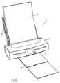
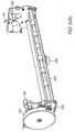
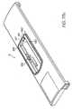
- the present inventionresides in a print engine 1 that can be readily incorporated into a body of a printer unit 2 to perform the printing functions of the printer unit
- the printer unit 2which incorporates the print engine 1, may be in any form but typically has a media supply region 3 for supporting and supplying media 8 to be printed by the print engine, and a media output or collection region 4 for collecting the printed sheets of media.
- the printer unit 2may also have a user interface 5 for enabling a user to control the operation of the printer unit, and this user interface 5 may be in the form of an LCD touch screen as shown.
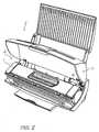
- the printer unit 2typically has an internal cavity 6 for receiving the print engine 1, and access to the internal cavity may be provided by a lid 7 which is hingedly attached to the body of the printer unit 2.
- the print engine 1is configured to be positioned and secured within the printer unit 2 such that media 8 located in media supply region 3 can be fed to the print engine 1 for printing and delivered to the collection region 4 for collection following printing.
- the print engine 1includes media transport means which take the sheets of media 8 from the media supply region 3 and deliver the media past the printhead assembly, where it is printed, into the media output tray 4.
- a picker mechanism 9is provided with the printer unit 2 to assist in feeding individual streets of media 8 from the media supply 3 to the print engine 1.
- the printer unit 2is arranged to print documents received from an external source, such as a computer system 702, onto a print media, such as a sheet of paper.
- the printer unit 100includes means which allow electrical connection between the printer unit 2 and the computer system 702 to receive data which has been pre-processed by the computer system 702.
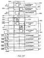
- the external computer system 702is programmed to perform various steps involved in printing a document, including receiving the document (step 703), buffering it (step 704) and rasterizing it (step 706), and then compressing it (step 708) for transmission to the printer unit 2.
- the printer unit 2receives the document from the external computer system 702 in the form of a compressed, multi-layer page image, wherein control electronics provided within the print engine 1 buffers the image (step 710), and then expands the image (step 712) for further processing.
- the expanded contone layeris dithered (step 714) and then the black layer from the expansion step is composited over the dithered contone layer (step 716).
- Coded datamay also be rendered (step 718) to form an additional layer, to be printed (if desired) using an infrared ink that is substantially invisible to the human eye.
- the black, dithered contone and infrared layersare combined (step 720) to form a page that is supplied to a printhead for printing (step 722).
- the data associated with the document to be printedis divided into a high-resolution bi-level mask layer for text and line art and a medium-resolution contone color image layer for images or background colors.
- colored textcan be supported by the addition of a medium-to-high-resolution contone texture layer for texturing text and line art with color data taken from an image or from flat colors.
- the printing architecturegeneralises these contone layers by representing them in abstract "image” and “texture” layers which can refer to either image data or flat color data.
- This division of data into layers based on contentfollows the base mode Mixed Raster Content (MRC) mode as would be understood by a person skilled in the art.
- MRCMixed Raster Content
- the printing architecturemakes compromises in some cases when data to be printed overlap. In particular, in one form all overlaps are reduced to a 3-layer representation in a process (collision resolution) embodying the compromises explicitly.
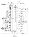
- datais delivered to the printer unit 2 in the form of a compressed, multi-layer page image with the pre-processing of the image performed by a mainly software-based computer system 702.
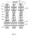
- the print engine 1processes this data using a mainly hardware-based system as is shown in more detail in Figure 4 .
- a distributor 730Upon receiving the data, a distributor 730 converts the data from a proprietary representation into a hardware-specific representation and ensures that the data is sent to the correct hardware device whilst observing any constraints or requirements on data transmission to these devices.
- the distributor 730distributes the converted data to an appropriate one of a plurality of pipelines 732.
- the pipelinesare identical to each other, and in essence provide decompression, scaling and dot compositing functions to generate a set of printable dot outputs.
- Each pipeline 732includes a buffer 734 for receiving the data.
- a contone decompressor 736decompresses the color contone planes, and a mask decompressor decompresses the monotone (text) layer.
- Contone and mask scalers 740 and 742scale the decompressed contone and mask planes respectively, to take into account the size of the medium onto which the page is to be printed.
- the scaled contone planesare then dithered by ditherer 744.
- a stochastic dispersed-dot ditheris used. Unlike a clustered-dot (or amplitude-modulated) dither, a dispersed-dot (or frequency-modulated) dither reproduces high spatial frequencies (i.e. image detail) almost to the limits of the dot resolution, while simultaneously reproducing lower spatial frequencies to their full color depth, when spatially integrated by the eye.
- a stochastic dither matrixis carefully designed to be relatively free of objectionable low-frequency patterns when tiled across the image. As such, its size typically exceeds the minimum size required to support a particular number of intensity levels (e.g. 16 x 16 x 8 bits for 257 intensity levels).
- the dithered planesare then composited in a dot compositor 746 on a dot-by-dot basis to provide dot data suitable for printing.
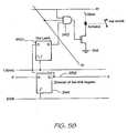
- This datais forwarded to data distribution and drive electronics 748, which in turn distributes the data to the correct nozzle actuators 750, which in turn cause ink to be ejected from the correct nozzles 752 at the correct time in a manner which will be described in more detail later in the description.
- the components employed within the print engine 1 to process the image for printingdepend greatly upon the manner in which data is presented.
- the print engine 1may employ additional software and/or hardware components to perform more processing within the printer unit 2 thus reducing the reliance upon the computer system 702.
- the print engine 1may employ fewer software and/or hardware components to perform less processing thus relying upon the computer system 702 to process the image to a higher degree before transmitting the data to the printer unit 2.
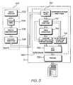
- SoPECSmall Office Home Office Printer Engine Chip
- a SoPEC deviceconsists of 3 distinct subsystems: a Central Processing Unit (CPU) subsystem 771, a Dynamic Random Access Memory (DRAM) subsystem 772 and a Print Engine Pipeline (PEP) subsystem 773.
- CPUCentral Processing Unit
- DRAMDynamic Random Access Memory
- PEPPrint Engine Pipeline
- the CPU subsystem 771includes a CPU 775 that controls and configures all aspects of the other subsystems. It provides general support for interfacing and synchronizing all elements of the print engine 1. It also controls the low-speed communication to QA chips (which are described delow).
- the CPU subsystem 771also contains various peripherals to aid the CPU, such as General Purpose Input Output (GPIO, which includes motor control), an Interrupt Controller Unit (ICU), LSS Master and general timers.
- GPIOGeneral Purpose Input Output
- ICUInterrupt Controller Unit
- LSS MasterGeneral Timers.
- the Serial Communications Block (SCB) on the CPU subsystemprovides a full speed USB1.1 interface to the host as well as an Inter SoPEC Interface (ISI) to other SoPEC devices (not shown).
- ISIInter SoPEC Interface
- the DRAM subsystem 772accepts requests from the CPU, Serial Communications Block (SCB) and blocks within the PEP subsystem.
- the DRAM subsystem 772and in particular the DRAM Interface Unit (DIU), arbitrates the various requests and determines which request should win access to the DRAM.
- the DIUarbitrates based on configured parameters, to allow sufficient access to DRAM for all requestors.
- the DIUalso hides the implementation specifics of the DRAM such as page size, number of banks and refresh rates.
- the Print Engine Pipeline (PEP) subsystem 773accepts compressed pages from DRAM and renders them to bi-level dots for a given print line destined for a printhead interface (PHI) that communicates directly with the printhead.
- the first stage of the page expansion pipelineis the Contone Decoder Unit (CDU), Lossless Bi-level Decoder (LBD) and, where required, Tag Encoder (TE).
- the CDUexpands the JPEG-compressed contone (typically CMYK) layers
- the LBDexpands the compressed bi-level layer (typically K)
- the TEencodes any Netpage tags for later rendering (typically in IR or K ink), in the event that the printer unit 2 has Netpage capabilities.
- the output from the first stageis a set of buffers: the Contone FIFO unit (CFU), the Spot FIFO Unit (SFU), and the Tag FIFO Unit (TFU).
- the CFU and SFU buffersare implemented in DRAM.
- the second stageis the Halftone Compositor Unit (HCU), which dithers the contone layer and composites position tags and the bi-level spot layer over the resulting bi-level dithered layer.
- HCUHalftone Compositor Unit
- a number of compositing optionscan be implemented, depending upon the printhead with which the SoPEC device is used. Up to 6 channels of bi-level data are produced from this stage, although not all channels may be present on the printhead.
- the printheadmay be CMY only, with K pushed into the CMY channels and IR ignored.
- any encoded tagsmay be printed in K if IR ink is not available (or for testing purposes).
- a Dead Nozzle Compensatorcompensates for dead nozzles in the printhead by color redundancy and error diffusing of dead nozzle data into surrounding dots.
- the resultant bi-level 5 channel dot-data(typically CMYK, Infrared) is buffered and written to a set of line buffers stored in DRAM via a Dotline Writer Unit (DWU).
- CMYKInfrared
- DWUDotline Writer Unit
- the dot-datais loaded back from DRAM, and passed to the printhead interface via a dot FIFO.
- the dot FIFOaccepts data from a Line Loader Unit (LLU) at the system clock rate (pclk), while the PrintHead Interface (PHI) removes data from the FIFO and sends it to the printhead at a rate of 2/3 times the system clock rate.
- LLULine Loader Unit
- PHIPrintHead Interface
- the DRAMis 2.5Mbytes in size, of which about 2Mbytes are available for compressed page store data.
- a compressed pageis received in two or more bands, with a number of bands stored in memory.
- a band of the pageis consumed by the PEP subsystem 773 for printing, a new band can be downloaded.
- the new bandmay be for the current page or the next page.
- the embedded USB 1.1 deviceaccepts compressed page data and control commands from the host PC, and facilitates the data transfer to either the DRAM (or to another SoPEC device in multi-SoPEC systems, as described below).
- SoPEC devicescan be used in alternative embodiments, and can perform different functions depending upon the particular implementation. For example, in some cases a SoPEC device can be used simply for its onboard DRAM, while another SoPEC device attends to the various decompression and formatting functions described above. This can reduce the chance of buffer under-run, which can happen in the event that the printer commences printing a page prior to all the data for that page being received and the rest of the data is not received in time. Adding an extra SoPEC device for its memory buffering capabilities doubles the amount of data that can be buffered, even if none of the other capabilities of the additional chip are utilized.
- Each SoPEC systemcan have several quality assurance (QA) devices designed to cooperate with each other to ensure the quality of the printer mechanics, the quality of the ink supply so the printhead nozzles will not be damaged during prints, and the quality of the software to ensure printheads and mechanics are not damaged.
- QAquality assurance
- each printing SoPECwill have an associated printer unit QA, which stores information relating to the printer unit attributes such as maximum print speed.
- the cartridge unitmay also contain a QA chip, which stores cartridge information such as the amount of ink remaining, and may also be configured to act as a ROM (effectively as an EEPROM) that stores printhead-specific information such as dead nozzle mapping and printhead characteristics.
- the refill unitmay also contain a QA chip, which stores refill ink information such as the type/colour of the ink and the amount of ink present for refilling.
- the CPU in the SoPEC devicecan optionally load and run program code from a QA Chip that effectively acts as a serial EEPROM. Finally, the CPU in the SoPEC device runs logical QA chip (ie, a software QA chip).
- Each SoPEC devicehas two LSS system buses that can communicate with QA devices for system authentication and ink usage accounting.
- a large number of QA devicescan be used per bus and their position in the system is unrestricted with the exception that printer QA and ink QA devices should be on separate LSS busses.
- the logical QAcommunicates with the ink QA to determine remaining ink.
- the reply from the ink QAis authenticated with reference to the printer QA.
- the verification from the printer QAis itself authenticated by the logical QA, thereby indirectly adding an additional authentication level to the reply from the ink QA.
- Data passed between the QA chipsis authenticated by way of digital signatures.
- HMAC-SHAL authenticationis used for data
- RSAis used for program code, although other schemes could be used instead.
- the SoPEC devicetherefore controls the overall operation of the print engine 1 and performs essential data processing tasks as well as synchronising and controlling the operation of the individual components of the print engine 1to facilitate print media handling, as will be discussed below.
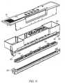
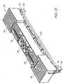
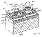
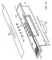
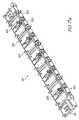
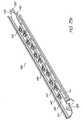
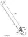
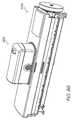
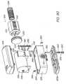
- the print engine 1is shown in detail in Figs. 6 - 8 and consists of two parts: a cartridge unit 10 and a cradle unit 12.
- the cartridge unit 10is shaped and sized to be received within the cradle unit 12 and secured in position by a cover assembly 11 mounted to the cradle unit.
- the cradle unit 12is provided with an external body 13 having anchor portions 14 which allow it to be fixed to the printer unit 2 in a desired position and orientation, as discussed above, to facilitate printing.
- the print engine 1is able to control various aspects associated with printing, including transporting the media past the printhead in a controlled manner as well as the controlled ejection of ink onto the surface of the passing media.
- the print engine 2may also include electrical contacts which facilitate electrical connection with the user interface 5 of the printer unit 2 to enable control of the print engine 1.
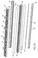
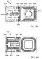
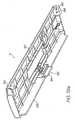
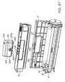
- the cartridge unit 10is shown in detail in Figs. 9 -12 .
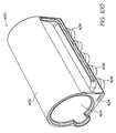
- the cartridge unit 10generally consists of a main body 20, a lid assembly 21, a printhead assembly 22 and a capper assembly 23.
- the cartridge unit 10has facilities for receiving a refill supply of ink to replenish the ink storage when necessary and the cartridge unit itself carries an integral capping assembly 23 for capping the printhead when not in use.
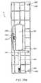
- the main body 20 of the cartridge unit 10is shown in more detail in Figs 13 - 15 and comprises a moulded plastics body which defines a plurality of ink storage compartments 24 in which the various colours and/or types of ink are stored. Each of the ink storage compartments 24 are separated from one another to prevent mixing of the different inks, as is shown more clearly in Figure 14 , and extend along the length of the main body 20.
- each of the ink storage compartments 24is provided with a raised portion 26 which surrounds an ink outlet 27, through which the ink flows for supply to the printhead assembly 22.
- the raised portions 26are typically moulded into the main body 20 and act to separate the outlet 27 from the base 25 of the ink storage compartment 24 to ensure a sufficient flow rate of ink from the compartment 24.
- an air barrier/ink filter 28 made from a fine mesh materialis placed over the ink outlet 27, atop of the raised portions 26, thereby leaving a space between the filter and the outlet for receiving ink.
- the air barrier/ink filter 28is formed such that ink can readily pass through the mesh to the printhead assembly 22 but any air bubbles present in the ink are prevented from passing through.
- the ink storage compartments 24are provided with an absorbent material 29 such as a foam for storing the ink.
- the absorbent material 29is shaped to conform to the shape of the ink storage compartment 24 and is fitted within the corresponding compartment to be supported on top of the air barrier/ink filter 28. In this arrangement, the lower surface of the absorbent material 29 is separated from the base 25 of the ink storage compartments via the raised portions 26.
- the absorbent material 29acts to absorb ink supplied to the compartment 24 such that the ink is suspended internally within.
- the manner in which ink is supplied to the compartment 24will be discussed in more detail later, however it should be appreciated that the structure of the absorbent material is such that it contains a number of open pores which receive and draw in the ink under capillary action.
- the inkfills the space between the ink filter/air barrier 28 and the outlet 27 thereby forming an ink dam, which is in fluid communication with the ink in the printhead assembly 22 and the ink suspended within the absorbent material 29. Due to the nature of the absorbent material 29 and the fact that the ink is retained therein under capillary action, a back pressure is created which prevents the ink from freely flowing from the compartment 24 and out the nozzles of the printhead assembly 22.
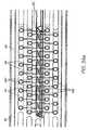
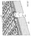
- the absorbent material 29may be provided as a block or stack of layers made from a polymer material, such as polycarbonate, acrylic, polysulfone, polystyrene, fluoropolymer, cyclic olefin polymer, cyclic olefin copolymer, etc, having the channels 16 formed therein in the form of a micro-capillary array, as shown in Fig. 16 , with each channel having an average diameter of about 10 microns or less.
- a polymer materialsuch as polycarbonate, acrylic, polysulfone, polystyrene, fluoropolymer, cyclic olefin polymer, cyclic olefin copolymer, etc, having the channels 16 formed therein in the form of a micro-capillary array, as shown in Fig. 16 , with each channel having an average diameter of about 10 microns or less.
- the body of the absorbent material 29, in which the micro-capillary array of the channels 16 is formedremains stable and rigid at all times. That is, the rigid walls of the channels remain intact during exposure to the ink whereby particulate matter is not introduced into the ink, unlike the cellular or interlaced arrangement of compressible pores within the conventional foam and sponge materials which contribute to contaminant production.
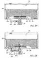
- the absorbent material 29 having the channels 16 formed as a micro-capillary array thereincan be arranged within the individual ink storage compartments 24 as shown in Fig 17 .
- An ink trapping layer 17is provided between the ink filter/air barrier 28 and the absorbent material 29.
- the trapping layer 17absorbs the supplied ink in multiple-directions, thus allowing for the ingress of the ink into the longitudinally orientated channels 16, and in this regard merely acts as a means for presenting the ink to the channels 16.
- the trapping layer 17may be provided as a foam or sponge material with a thickness substantially less than that of the absorbent material 29, since the function of the trapping layer is merely to supply ink to the channels16 of the absorbent material 29 and not to store the ink.
- the ink drawn into and stored within the channels 16is able to pass to the nozzles of the printhead assembly 22 via the ink trapping layer 17.
- the use of foam or sponge material in the ink trapping layer 17may result in some particulate contamination occurring in the ink. However, this may be minimized by providing the layer with a thickness and density which is just sufficient for absorbing the necessary amount of ink for effective absorption into the channels 16. In any event, since the ink is effectively stored only in the absorbent material 29, the contaminant level that may be produced in the ink trapping layer is significantly reduced from the levels produced by the conventional structures.
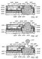
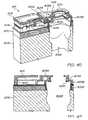
- a pressed metal chassis 30is fitted to the underside of the main body via clips 31 formed in the chassis 30 which mate with corresponding clips formed in the main body 20.
- the pressed metal chassis 30is shaped to conform to the underside of the main body 20 and includes a plurality of holes 32 that extend therethrough which are positioned to correspond with the ink outlets 27 of the ink storage compartments 24 such that there is a passage for ink to pass through the chassis 30.
- the chassis 30provides additional stability to the cartridge unit 10 and includes an edge 33 that extends downwardly from the main body 20 which defines a contact region where the flex printed circuit board 52 of the printhead assembly 22 contacts with corresponding electrical contacts 128 in the cradle unit 12, in a manner which will be described in more detail later in the description.
- the chassis 30also has a plurality of elongate recesses 34 formed along its length, through which connecting clips provided on the printhead assembly 22 pass, for connection to the main body 20, as will be described in more detail below.
- a seal moulding 35is attached to the chassis 30 to complete and seal the ink flow path from the ink storage compartments 24 through the chassis 30.
- the seal moulding 35is made from an elastomeric material and has a plurality of hollow cylindrical inserts 36 formed along its surface which extend through the holes 32 formed in the chassis 30 and into the ink outlets 27 of each of the ink storage compartments 24, as shown in Fig 15 .
- the distal ends of the hollow cylindrical inserts 36abut with the main body 20 to seal the ink outlets 27 and ensure ink flow through the seal moulding 35.
- the seal moulding 35is fixed to the surface of the metal chassis 30 by a lock-fit or a suitable adhesive and acts to provide a substantially planar surface upon which the printhead assembly 22 is attached.
- the planar surfacehaving a plurality of outlet holes 39 provided therein through which ink can flow to the printhead assembly.
- a flex printed circuit board (PCB) backer 37is attached to the side of the main body 20 via locating studs 38 and extends over the downwardly projecting edge 33 of the chassis 30.
- the flex PCB backer 37is made from a suitable elastomeric material and provides a backing onto which the flex PCB 52 of the printhead assembly 22 is supported following attachment of the printhead assembly 22 to the main body 20.
- the flex PCB 52 from the printhead assembly 22is provided with a suitable recess which fits over the locating studs 38 such that the electrical dimpled contacts 53 formed on the flex PCB 52 are positioned over the flex PCB backer 37 and extend outwardly therefrom to contact suitable electrical contacts 128 provided in the cradle unit 12.
- This arrangementprovides some degree of flexibility in this contact region such that appropriate electrical contact can be established between the cradle unit 12 and the cartridge unit 10 to allow the transmission of data and power therebetween to control the ink ejecting nozzles of the printhead assembly 22.
- This arrangementalso ensures that the forces associated with the contact between the cartridge unit 12 and the cradle unit 10 in this region are carried by the chassis 30 and not transferred to the printhead assembly 22 which could cause damage to the delicate printhead integrated circuits.
- the main body 20also includes a pair of end supports 40 which extend from the main body 20 in a downward direction with respect to the cartridge unit 10.
- the end supports 40are arranged such that the seal moulding 35 and the flex PCB backer 37 extend along the main body 20 between the two end supports 40. The purpose of the end supports 40 will be described later in the description.
- the printhead assembly 22is shown in more detail in Figs. 18 to 21 , and is adapted to be attached to the underside of the main body 20 to receive ink from the outlet holes 39 formed in the planar surface of the seal moulding 35.
- the printhead assembly 22comprises an upper moulding 42, having features which facilitate connection of the printhead assembly to the main body 20 of the cartridge unit 10. These features are in the form of u-shaped clips 43 that project from the surface of the upper moulding 42.
- the clips 43pass through the elongate recesses 34 provided in the chassis 30 and become captured by lugs (not shown) formed in the main body 20, thereby securing the printhead assembly 22 to the main body 20.
- the surface of the upper moulding 42has a plurality of ink inlets 44 which project therefrom.
- the ink inlets 44are received within the outlet holes 39 of the seal moulding 35, when the printhead assembly 22 is secured to the main body 20, and provide a path for the ink to flow to the printhead integrated circuits for printing.
- the ink inlets 44are shaped to fit within the outlet holes 39 of the seal moulding 35 and may also be provided with an outer coating that facilitates sealing.
- the upper moulding 42is made from a liquid crystal polymer (LCP) and is bonded to a lower moulding 45 via an adhesive film 46.
- the lower moulding 45is also made from an LCP and has a plurality of channels 47 formed along its length. Each of the channels 47 are provided to receive ink from one of the ink storage compartments 24, via an ink inlet 44, and distribute the ink along the length of the printhead assembly 22 for feeding to the ink delivery nozzles 51 of the printhead assembly 22.
- the channelspreferably have a width of 1 mm and are separated by walls having a width of 0.75 mm.
- the lower moulding 45has five channels 47 extending along its length with each of the ink channels 47 receiving ink from one of the corresponding ink inlets 44.
- the adhesive film 46also acts to seal the individual ink channels 47 and prevent cross channel mixing of the ink when the lower moulding 45 is assembled to the upper moulding 42.
- an ink distribution member 48is attached to the lower moulding 45 and acts as an interface between the printhead ICs 50 and the ink channels 47 of the lower moulding 45.
- the purpose of the ink distribution member 48is to provide a flow path for ink to flow from the relatively wide channels 47 to the relatively small and narrow channels 98 formed on the underside of the printhead ICs 50 which feed the ink to the individual ink delivery nozzles 51.
- the ink distribution member 48functions to perform millimetric-to-micrometric fluid distribution to the nozzles of the printhead ICs 50
- the present inventionis related to page-width printing and as such the printhead ICs 50 are arranged to extend horizontally across the width of the passing media to deposit ink droplets thereon to create an image.
- individual printhead ICs 50are linked together in abutting arrangement across the surface of the ink distribution member 48 of the printhead assembly 22, as shown simply in Fig 22 .
- the length of an individual printhead IC 50is around 20 - 22 mm and as such in order to print an A4/US letter sized page, 11 - 12 individual printhead ICs 50 may be linked together in abutting fashion.
- Other printing sizesmay also be possible and as such the number of individual printhead ICs 50 required may vary depending upon the application.
- Each printhead IC 50has a plurality of individual ink delivery nozzles 51 formed therein, the structure and control of which will be described in more detail later.
- the nozzles 51 within an individual printhead IC 50are grouped physically to reduce ink supply complexity and wiring complexity, and are also grouped logically to minimize power consumption and to allow a variety of printing speeds.
- each printhead IC 50is able to print five different colours ( C; M, Y, K and IR) and contains 1280 ink delivery nozzles 51 per colour, with these nozzles being divided into even and odd nozzles (640 each). Even and odd nozzles for each colour are provided on different rows on the printhead IC 50 and are aligned vertically to perform true 1600 dpi printing, meaning that the nozzles 51 are arranged in 10 rows.
- the horizontal distance between two adjacent nozzles 51 on a single rowis 31.75 microns, whilst the vertical distance between rows of nozzles is based on the firing order of the nozzles, but rows are typically separated by an exact number of dot lines, plus a fraction of a dot line corresponding to the distance the paper will move between row firing times Also, the spacing of even and odd rows of nozzles for a given colour must be such that they can share an ink channel, as will be described below.
- the manner in which individual printhead ICs 50 are linked together in abutting fashionmay be performed in a variety of ways. As shown in Fig. 23 , the simplest way to achieve this linkage of the printhead ICs 50 is to form a rectangular join between adjacent ICs 50. However, due to the nature of this rectangular join, it may result in a gap between adjacent nozzles at the join interface which could produce a vertical stripe down the printed page of media where no ink is deposited, which may be unacceptable in some printing applications.
- the ICs 50may be provided with a vertical offset, as shown in Fig 25 .
- This offsetcan be seen by the vertical offset between the longitudinal edges of adjacent ICs 50, and this offset increases with each join along the length of the printhead assembly 22. For example, if the offset was equivalent to 7 lines of nozzles per join, then for 11 ICs joined in this manner, there would be a total of 10 joins and 70 additional nozzle lines. This then results in an increase in the lines of data storage required for the printhead assembly.
- each IC 50may be placed on a mild slope to achieve a constant number of print lines regardless of the number of joins, as shown in Fig. 26 .
- Fig. 27a and 27bYet another system for linking the ICs 50 in abutting fashion is shown in Fig. 27a and 27b .
- the ICs 50are shaped at their ends to link together to form a horizontal line of ICs, with no vertical offset between neighboring ICs.
- a sloping joinis provided between the ICs which has a 45 degree angle to the upper and lower chip edges.
- the joining edgeis not straight and has a sawtooth profile to facilitate positioning, and the ICs 50 are intended to be spaced about 11 microns apart, measured perpendicular to the joining edge.
- the left most ink delivery nozzles on each roware dropped by 10 line pitches and arranged in a triangle configuration as shown in Fig 27a and Figs.
- This arrangementprovides a degree of overlap of nozzles at the join and maintains the pitch of the nozzles to ensure that the drops of ink are delivered consistently along the printing zone. This arrangement also ensures that more silicon is provided at the edge of the IC 50 to ensure sufficient linkage. Control of the operation of the nozzles is performed by the SoPEC device, however compensation for the nozzles is performed in the printhead, or may also be performed by the SoPEC device, depending on the storage requirements. In this regard it will be appreciated that the dropped triangle arrangement of nozzles disposed at one end of the IC 50 provides the minimum on-printhead storage requirements. However where storage requirements are less critical shapes other than a triangle can be used, for example, the dropped rows may take the form of a trapezoid.
- Fig. 28ashows more clearly the upper surface of a portion of the individual ICs.
- bond pads 96are provided along an edge thereof which provide a means for receiving data and or power to control the operation of the nozzles from the SoPEC of the cradle unit 12.
- Fiducials 97are also provided on the surface of the ICs to assist in positioning and aligning the ICs 50 with respect to each other.
- the fiducials 97are in the form of markers that are readily identifiable by appropriate positioning equipment to indicate the true position of the IC 50 with respect to a neighbouring IC 50, and are strategically positioned at the edges of the IC, proximal the join.
- the fiducials 97align with corresponding fiducials 97 provided on the surface of a neighbouring IC 50 to ensure alignment of the ICs to appropriate limits, as discussed above.
- the underside of a printhead IC 50is shown in relation to Fig 28c .
- a number of etched channels 98there are provided a number of etched channels 98, with each channel 98 in communication with a pair of rows of nozzles 51.
- the channels 98are about 80 microns wide and extend the length of the IC 50 and include silicon walls 99 formed therein, to divide the channels 98 into portions.
- the channelsare adapted to receive ink from the ink channels 47 of the lower moulding 45 and distribute the ink to the pair of rows of nozzles 51 to eject that ink of a specific colour or type.
- each portionfeeds approximately 128 nozzles and is individually fed a supply of ink.
- Each of the ICs 50are positioned and secured to the surface of the ink distribution member 48.
- the ink distribution memberdelivers the ink from the 1 mm wide channels 47 formed in the lower moulding 45 to the 80 micron wide channels 98 formed in the underside of the printhead ICs 50.
- the ink distribution member 48can be configured in a number of forms.
- the ink distribution member 48may be in the form of a laminated structure consisting of a number of layers bonded to one another, as described in U.S. Patent No. 6,409,323 and pending US Application No. 2004/0113997 ..
- the ink distribution member 48may be in a two-part form comprising an intermediate layer 172 and an adhesive layer 173, as shown in Fig. 29 .
- the intermediate layer 172is arranged to fit over the exposed channels 47 of the lower moulding 45 to seal the channels 47 and to form a sealed unit with the lower moulding 45.
- the intermediate layer 172has a plurality of holes 174 formed therethrough along its length each of which are aligned with the channels 47 and are spaced at regular intervals along the length thereof.
- the holes 174 formed through the intermediate layer 172 which relate to the most central channel 47 of the lower moulding 45are in the form of small diameter holes equi-spaced at intervals along the length of the intermediate layer 172. Larger diameter holes 174 are provided which correspond to the other channels 47 of the lower moulding 45, which are displaced laterally from the most central channel. These holes 174 are similarly equi-spaced along the length of the intermediate layer and micro conduits 176 are provided which extend from the larger diameter holes to terminate at a central region of the intermediate layer 172, proximal the smaller diameter holes. These conduits 176 distribute the ink from each of the holes 172 to a central region of the intermediate layer to deliver the different types/colours of ink to the channels 98 formed in the underside of the integrated circuits 50.
- the intermediate layer 172is also made from a liquid crystal polymer (LCP) which is injection moulded to the appropriate shape and configuration.
- LCPliquid crystal polymer
- the intermediate layer 172is bonded to the lower moulding 45 via a thermal adhesive, such as 3M 816 or Abelflex 5206 or 5205, which is applied between the intermediate layer 172 and the lower moulding 45 and placed in a laminator.
- the bonding film 175is applied to the surface of the intermediate layer 172.
- the bonding film 175is in the form of a laminate polymer film which may be a thermoplastic film such as a PET or Polysulphone film, or it may be in the form of a thermoset film, such as those manufactured by AL technologies and Rogers Corporation.
- the bonding film 175preferably has co-extruded adhesive layers formed on both sides thereof and is laminated onto the upper surface of the intermediate layer 172
- holesare drilled through the bonding layer 175 to coincide with the centrally located small diameter holes 174, and the ends of the conduits 176. This is shown in Fig. 31 . These holes provide a separate flow passage through the bonding layer 175 for each of the different types of inks, which feed directly to the appropriate channel portions 98 formed on the underside of the integrated circuits 50 for supply to the ink delivery nozzles 51 associated with each channel portion 98, as discussed above. Fiducial locating marks 177 are also drilled into the surface of the bonding layer to assist in attaching and positioning the ICs 50 thereon.
- the ICs 50are placed in a die and heated to 170° C and then pressed into the bonding layer 175 at 40 psi pressure for about 3 seconds. This results in the ICs 50 being thermally bonded to the intermediate layer 172, as shown in Fig 32 .
- the fiducial locating marks 177 formed in the surface of the bonding layer 175aid in positioning the ICs such that the channels 98 formed in the underside of the ICs 50 correctly align with the holes drilled through the bonding layer 175 to provide a flow path for ink to be fed to the nozzles for printing.
- the ink distribution member 48is in the form of a two part element containing an intermediate layer 172 which fits over the channels 47 formed in the lower moulding 45, and a bonding layer 175 allowing fluid flow therethrough and which acts to attach the ICs to the surface of the intermediate layer 172.
- the ink distribution member 48may be in the form of a one-piece element with the ICs being directly attached to its upper surface.
- the conduitsare formed within the body of the ink distribution member 48 such that the upper surface of the ink distribution member only has small diameter holes formed centrally therein for delivering the ink to the undersurface of the ICs.
- FIGs 33a - 33cThe manner in which this is achieved is shown in Figs 33a - 33c . These Figures merely show the manner in which the ink can be directed from one of the channels 47 of the lower moulding 45, and it will be appreciated that the same approach can be similarly applied to deliver ink from the remainder of the channels 47.
- the underside of the ink distribution member 48is provided with a plurality of holes or inlets 180 therein, each having a diameter of approximately 1 mm, which corresponds to the width of the channels 47 provided in the lower moulding 45.
- the inlets 180do not extend through the body of the ink distribution member 48, but rather extend into the member 48 to a depth of about a 3/4 the thickness of the member 48, as shown in the sectioned view of Fig 33c .
- an outlet 182in the form of a 80 micron wide hole, is provided in the uppermost surface of the ink distribution member 48 which extends into the end wall of the inlet 180 to provide a path for the ink to flow out of the ink distribution member.
- a tunnel 181is provided from a side wall of the inlet 180 within the ink distribution member 48 which acts to direct the flow of the ink received in the inlet through the body of the ink distribution member 48 to a central position therein.
- An outlet 182is then formed on an uppermost side of the ink distribution member to provide a path for the ink present in the tunnel 181 to exit the ink distribution member at the desired position along the surface of the ink distribution member.
- the outlets 182are essentially 80 microns in width, to correspond with the width of the channels 98 provided on the underside of the integrated circuits 50.
- the ink distribution member 48 of this embodimentis made from a photo-structurable glass-ceramic material, such as Forturan glass. These materials, when exposed to specific levels of pulsed UV laser energy density (fluence), have a photo-chemical reaction which creates a density of nanocrystals within the volume thereof, the density of which is directly proportional to the fluence of the exposed laser beam.
- the ink distribution member 48in order to form the desired inlets 180, outlets 182 and tunnels 181 connecting the inlets and outlets, the ink distribution member 48 is mounted upon a precision XYZ stage for exposure to a focussed laser beam.
- Various toolsmay be used to control the size and shape of the critically exposed volume of the glass structure to ensure that the desired pattern and shape is created within the ink distribution member. Typical exposure times may vary from 15 minutes to 1 hour.
- the ink distribution memberis loaded into an oven for thermal treatment to aid in causing crystallisation of exposed regions of the glass.
- the exposed and thermally treated glassis then loaded into a mild etchant for around 7 minutes to etch the exposed regions, however the etch time may vary dependant upon the thickness of the glass and the depth of the cut.
- the thermal treatment and etching stepsmay be repeated in order to form the complete ink distribution member as shown in the figures.
- ink present in the channels 47 of the lower moulding 45is drawn into the ink distribution member 48 via inlets 180 which are positioned over the channels 47 at regular intervals therealong.
- the inkis directed to a central region of the ink distribution member 48 via the above mentioned tunnels 181, where the ink can then exit the ink distribution member 48 via the outlets 182 at a predetermined position which is aligned with the corresponding channels 98 formed in the underside of the ICs 50.
- the ICs 50are secured to the upper surface of the ink distribution member 48 to receive the ink therefrom, using spun coated adhesive applied to the underside of the IC 50, or by screen printing epoxy on the upper surface of the ink distribution member 48.
- the fiducials provided on the ICs 50 and on the surface of the ink distribution member 48assist in positioning the ICs 50 such that the channels 98 formed in the underside of the ICs 50 are aligned with the appropriate outlet 182 formed in the upper surface of the member 48 to receive the correct type/colour of ink.
- Figs. 34a and 34bshow the manner in which this is arranged to control the delivery of ink from the five channels 47 of the lower moulding 45. These figures provide a top view of the arrangement and for reasons of clarity, the various elements are shown in outline to indicate the manner in which ink flows between the elements.
- Fig 34ais a top view of the arrangement showing the ICs 50 located centrally upon the ink distribution member 48.
- the ink distribution member 48is in turn secured to the lower moulding 45 such that the inlets 180 align with the respective channels 47 at regular intervals along the length thereof to receive ink from the channels 47 for distribution to the ICs 50.
- the inlets 180 associated with the central channel 47are in direct fluid communication with an outlet 182, which delivers the ink to the underside of the ICs 50.
- the inlets 180 associated with the other channels 47include tunnels 181 formed within the ink distribution member 48 which are in fluid communication with associated outlets 182 disposed remote from the inlets 180 to deliver ink to the underside of the ICs 50.
- the outlets 182are centrally arranged on the upper surface of the ink distribution member in a predetermined pattern, with the position of each outlet defining a point at which ink of a specific colour is delivered to the IC 50.
- Fig 34bis a magnified view of Fig 34a , showing in detail the manner in which the ink is supplied to the underside of the ICs 50.
- the channels 98 formed on the underside of the IC 50are clearly shown, as are the silicon walls 99 provided along the length of the channels 98, which divide the channels 98 into portions.
- the ICs 50are positioned on the surface of the ink distribution member such that the outlets 182 align with the channels 98 at the junction of the channel portions, namely at the region where the silicon walls 99 are situated. This then ensures that one outlet 182 supplies ink to two channel portions, allowing a regular spacing of outlets to be achieved along the surface of the ink distribution member 48.
- the ink distribution member 48is in the form of a on-piece element thereby overcoming the need to provide separate layers and reducing the complexity of the system, as sealing between layers is no longer required.
- a flex PCB 52is attached along an edge of the ICs 50 so that control signals and power can be supplied to the bond bads 96 of the ICs 50 to effect printing.
- the flex PCB 52folds around the printhead assembly 22 in an upward direction with respect to the cartridge unit 10, and has a plurality of dimpled contacts 53 provided along its length for receiving power and or data signals from the control circuitry of the cradle unit 12.
- a plurality of holes 54are also formed along the distal edge of the flex PCB 52 which provide a means for attaching the flex PCB 52 to the locating studs 38 formed on the main body 20, such that the dimpled contacts 53 of the flex PCB 52 extends over the flex PCB backer 37.
- the manner in which the dimpled contacts 53 of the flex PCB 52 contact the power and data contacts 128 of the cradle unit 12is described later.
- a media shield 55is attached to the printhead assembly 22 along an edge thereof and acts to protect the printhead ICs 50 from damage which may occur due to contact with the passing media.
- the media shield 55is attached to the upper moulding 42 upstream of the printhead ICs 50 as shown more clearly in Fig. 21 , via an appropriate clip-lock arrangement or via an adhesive. When attached in this manner, the printhead ICs 50 sit below the surface of the media shield 55, out of the path of the passing media.
- a space 56is provided between the media shield 55 and the upper 42 and lower 45 moulding which can receive pressurized air from an air compressor or the like. As this space 56 extends along the length of the printhead assembly 22, compressed air can be supplied to the space 56 from either end of the printhead assembly 22 and be evenly distributed along the assembly.
- the inner surface 57 of the media shield 55is provided with a series of fins 58 which define a plurality of air outlets evenly distributed along the length of the media shield 55 through which the compressed air travels.
- This arrangementtherefore provides a stream of air across the printhead ICs 50 in the direction of the media delivery which acts to prevent dust and other particulate matter carried with the media from settling on the surface of the printhead ICs, which could cause blockage and damage to the nozzles.
- FIG. 21A cross section of the complete printhead assembly 22 is shown in Fig. 21 .
- inkis received from the ink storage compartments 24 via the ink inlets 44 of the upper moulding 42, which feed the ink directly into one of the ink channels 47 of the lower moulding 45.
- the inkis in turn fed from the ink channels 47 to the ink delivery nozzles 51 of the printhead ICs 50 by way of the ink distribution member 48.
- the lower moulding 45is provided with a plurality of priming inlets 59 at one end thereof.
- Each of the priming inlets 59communicate directly with one of the channels 47 and provide a means for priming the printhead assembly 22 and the ink storage compartments 24 with ink prior to shipment and use.
- Figs 35 - 40Various ways in which the priming is achieved will now be described with reference to Figs 35 - 40 .
- Fig. 35is a simplified cross-sectional representation of an ink storage compartment 24 as described previously.
- Inkis primed into the absorbent material 29 through the ink outlet 27 which links the compartment 24 to the channels 47 of the printhead assembly 22.
- the inkis supplied via the priming inlets 59 along the channels 47 of the lower moulding 45, with each channel 47 in fluid communication with one ink outlet 27 of an ink storage compartment 24 to deliver ink of a specific type/colour to that ink storage compartment 24.
- Priming of the ink storage compartments 24is typically performed prior to shipment of the cartridge unit 10 and as such, an ink source can be temporarily attached to the priming inlets 59, wherein upon completion of priming, the priming inlets can be capped/sealed.
- priming inkis supplied under pressure to the ink storage compartment 24 via the ink outlets 27.
- the priming inkflows into the space between the ink filter/air barrier 28 and the outlet 27, and is absorbed into the absorbent material 29 through the ink filter/air barrier 28.
- the inkbecomes suspended within the absorbent material due to capillary attraction forces.
- the inkis able to be continually drawn into the pores of the absorbent material 29 via capillary action (as shown by arrows B).
- ink present in the channels 47 of the lower moulding 45is also supplied to the ink delivery nozzles 51 of the integrated circuits 50, via the ink distribution member 48.
- the inkflows to the nozzles 51 to prime the individual nozzles with ink, and due to the capillary action of the absorbent material 29 in the ink storage compartments 24, a sufficient backpressure is established in the ink supply to prevent leakage of the ink out of the nozzles 51.
- the priming operationis ceased before the absorbent material becomes completely saturated and its upper surface becomes wet with ink, so that the necessary backpressure can be maintained.
- Thismay be controlled by limiting the supply of ink or by more sophisticated methods, such as sensing the level of ink within the body.
- Hydrophobic materialmay also be used on the surface of the ICs 50 in the vicinity of the nozzles 51 so as to assist in leakage prevention.
- FIG. 35 to 39An alternative embodiment for configuring the ink storage compartments 24 which provides a means of substantially obviating the need to limit the ink pressure during priming is illustrated in Figs. 35 to 39 .
- a bypass fluid path 185is provided in fluid communication with the ink outlet 27.
- the bypass fluid path 185allows the priming ink an additional path into the ink storage compartment 24 where it can be absorbed by the absorbent material 29.
- the priming inkdoes not only flow through the ink filter air barrier 28 directly into the absorbent material 29, but can also flow into at least a portion of a well region 24a of the compartment 24, as illustrated by arrows C in Fig. 36 .
- the well region 24ais the annular region surrounding the raised portions 26 on the base 25 of the compartments where there is a gap between the base 25 of the compartment 24 and the absorbent material 29. This well region 24a defines a space where the priming ink can be readily delivered via the bypass fluid path 185.
- the path 185is provided with a bypass valve 186 which is open during initial priming of the cartridge unit 10 and is closed upon completion of the priming operation, as shown in Fig. 37 .
- the bypass valve 186may be provided by way of a variety of arrangements and may be either manually or automatically controlled.
- the bypass valve 186may be provided as a manual depression button as illustrated in Figs. 38 and 39 .
- the bypass valve 186is in the form of a button 187 provided as a flexible portion of the bottom wall of the path 185.
- the button 187may be made from a rubber material and may be connected to the wall of the path 185 via an annular weakened portion 187a. Initially, and during priming, the button 187 is positioned as shown in Fig. 38 to allow the priming ink to flow through the path 185. Once priming is complete, the path 185 is closed by depressing the button 187 into a circular recessed region 188 of the internal wall of the path 185. In this regard, the button 187 is captured by the lip 189 and retained therein, thereby blocking the bypass valve 186, as shown in Fig. 39 .
- bypass valve structuresare possible and encompassed by the present invention.
- a simple alternative to the abovemay be providing the additional fluid path 185 as a compressible silicon tube or the like.
- the bypass valve 186may be configured to be irreversibly closed once the priming is completed. On the other hand, if refilling of the storage compartments via the priming inlets of the printhead assembly 22 is desired, a bypass valve capable of being opened and closed without limit may be provided.
- FIG. 40Another embodiment of the ink storage compartments 24 which provides an alternative or additional arrangement for priming the compartments 24 with ink is illustrated in Fig. 40 .
- a port 190is provided in at least one of the side walls of each compartment 24 in a position below the upper surface of the absorbent material 29.
- the ports 190are provided for the insertion of a needle 191 from an external ink source syringe or the like (not shown) which penetrates into the absorbent material 29, and through which the priming ink is supplied into the body.
- the ports 190are configured so that the needle 191 supplies the priming ink towards the lower portion of the absorbent material 29, shown with arrows D in Fig. 40 , so as to prevent wetting of the uppermost portion of the absorbent material 29, for the reasons discussed above.
- Each port 190is provided with a valve 192 which allows penetration of the needle 191 and is sealed when the needle is extracted and at other times.
- the valve 192may incorporate an elastomeric seal.
- the priming inkis delivered directly to the absorbent material 29 and through capillary force is suspended therein for delivery to the nozzles of the printhead assembly 22, as shown with arrow E in Fig. 40 .
- Figure 50shows an array of ink delivery nozzle arrangements 801 formed on a silicon substrate 8015.
- Each of the nozzles arrangements 801are identical, however groups of nozzle arrangements 801 are arranged to be fed with different colored inks or fixative.
- the nozzle arrangementsare arranged in rows and are staggered with respect to each other, allowing closer spacing of ink dots during printing than would be possible with a single row of nozzles.
- Such an arrangementmakes it possible to provide a high density of nozzles, for example, more than 5000 nozzles arrayed in a plurality of staggered rows each having an interspacing of about 32 microns between the nozzles in each row and about 80 microns between the adjacent rows.
- the multiple rowsalso allow for redundancy (if desired), thereby allowing for a predetermined failure rate per nozzle.
- Each nozzle arrangement 801is the product of an integrated circuit fabrication technique.
- the nozzle arrangement 801defines a micro-electromechanical system (MEMS).
- MEMSmicro-electromechanical system
- the ink jet printhead integrated circuit 50includes a silicon wafer substrate 8015 having 0.35 Micron 1 P4M 12 volt CMOS microprocessing electronics is positioned thereon.
- a silicon dioxide (or alternatively glass) layer 8017is positioned on the substrate 8015.
- the silicon dioxide layer 8017defines CMOS dielectric layers.
- CMOS top-level metaldefines a pair of aligned aluminium electrode contact layers 8030 positioned on the silicon dioxide layer 8017.
- Both the silicon wafer substrate 8015 and the silicon dioxide layer 8017are etched to define an ink inlet channel 8014 having a generally circular cross section (in plan).
- An aluminium diffusion barrier 8028 of CMOS metal 1, CMOS metal 2/3 and CMOS top level metalis positioned in the silicon dioxide layer 8017 about the ink inlet channel 8014.
- the diffusion barrier 8028serves to inhibit the diffusion of hydroxyl ions through CMOS oxide layers of the drive electronics layer 8017.
- a passivation layer in the form of a layer of silicon nitride 8031is positioned over the aluminium contact layers 8030 and the silicon dioxide layer 8017. Each portion of the passivation layer 8031 positioned over the contact layers 8030 has an opening 8032 defined therein to provide access to the contacts 8030.
- the nozzle arrangement 801includes a nozzle chamber 8029 defined by an annular nozzle wall 8033, which terminates at an upper end in a nozzle roof 8034 and a radially inner nozzle rim 804 that is circular in plan.
- the ink inlet channel 8014is in fluid communication with the nozzle chamber 8029.
- a moving rim 8010At a lower end of the nozzle wall, there is disposed a moving rim 8010, that includes a moving seal lip 8040.
- An encircling wall 8038surrounds the movable nozzle, and includes a stationary seal lip 8039 that, when the nozzle is at rest as shown in Fig. 44 , is adjacent the moving rim 8010.
- a fluidic seal 8011is formed due to the surface tension of ink trapped between the stationary seal lip 8039 and the moving seal lip 8040. This prevents leakage of ink from the chamber whilst providing a low resistance coupling between the encircling wall 8038 and the nozzle wall 8033.
- a plurality of radially extending recesses 8035is defined in the roof 8034 about the nozzle rim 804.
- the recesses 8035serve to contain radial ink flow as a result of ink escaping past the nozzle rim 804.
- the nozzle wall 8033forms part of a lever arrangement that is mounted to a carrier 8036 having a generally U-shaped profile with a base 8037 attached to the layer 8031 of silicon nitride.
- the lever arrangementalso includes a lever arm 8018 that extends from the nozzle walls and incorporates a lateral stiffening beam 8022.
- the lever arm 8018is attached to a pair of passive beams 806, formed from titanium nitride (TiN) and positioned on either side of the nozzle arrangement, as best shown in Fig. 44 and 49 .
- the other ends of the passive beams 806are attached to the carrier 8036.
- the lever arm 8018is also attached to an actuator beam 807, which is formed from TiN. It will be noted that this attachment to the actuator beam is made at a point a small but critical distance higher than the attachments to the passive beam 806.
- the actuator beam 807is substantially U-shaped in plan, defining a current path between the electrode 809 and an opposite electrode 8041.
- Each of the electrodes 809 and 8041are electrically connected to respective points in the contact layer 8030.
- the actuator beamis also mechanically anchored to anchor 808.
- the anchor 808is configured to constrain motion of the actuator beam 807 to the left of Figs. 44 to 46 when the nozzle arrangement is in operation.
- the TiN in the actuator beam 807is conductive, but has a high enough electrical resistance that it undergoes self-heating when a current is passed between the electrodes 809 and 8041. No current flows through the passive beams 806, so they do not expand.
- the device at restis filled with ink 8013 that defines a meniscus 803 under the influence of surface tension.
- the inkis retained in the chamber 8029 by the meniscus, and will not generally leak out in the absence of some other physical influence.
- a currentis passed between the contacts 809 and 8041, passing through the actuator beam 807.
- the self-heating of the beam 807 due to its resistancecauses the beam to expand.
- the dimensions and design of the actuator beam 807mean that the majority of the expansion in a horizontal direction with respect to Figs. 41 to 43 .
- the expansionis constrained to the left by the anchor 808, so the end of the actuator beam 807 adjacent the lever arm 8018 is impelled to the right.
- the relative horizontal inflexibility of the passive beams 806prevents them from allowing much horizontal movement the lever arm 8018.
- the relative displacement of the attachment points of the passive beams and actuator beam respectively to the lever armcauses a twisting movement that causes the lever arm 8018 to move generally downwards.
- the movementis effectively a pivoting or hinging motion.
- the absence of a true pivot pointmeans that the rotation is about a pivot region defined by bending of the passive beams 806.
- the downward movement (and slight rotation) of the lever arm 8018is amplified by the distance of the nozzle wall 8033 from the passive beams 806.
- the downward movement of the nozzle walls and roofcauses a pressure increase within the chamber 8029, causing the meniscus to bulge as shown in Fig. 42 .
- the surface tension of the inkmeans the fluid seal 8011 is stretched by this motion without allowing ink to leak out.
- the drive currentis stopped and the actuator beam 807 quickly cools and contracts.
- the contractioncauses the lever arm to commence its return to the quiescent position, which in turn causes a reduction in pressure in the chamber 8029.
- the interplay of the momentum of the bulging ink and its inherent surface tension, and the negative pressure caused by the upward movement of the nozzle chamber 8029causes thinning, and ultimately snapping, of the bulging meniscus to define an ink drop 802 that continues upwards until it contacts adjacent print media.
- meniscus 803forms the concave shape shown in Fig. 43 .
- Surface tensioncauses the pressure in the chamber 8029 to remain relatively low until ink has been sucked upwards through the inlet 8014, which returns the nozzle arrangement and the ink to the quiescent situation shown in Fig. 61 .
- the nozzle arrangement 1001is of a bubble forming heater element actuator type which comprises a nozzle plate 1002 with a nozzle 1003 therein, the nozzle having a nozzle rim 1004, and aperture 1005 extending through the nozzle plate.
- the nozzle plate 1002is plasma etched from a silicon nitride structure which is deposited, by way of chemical vapor deposition (CVD), over a sacrificial material which is subsequently etched.
- CVDchemical vapor deposition
- the nozzle arrangementincludes, with respect to each nozzle 1003, side walls 1006 on which the nozzle plate is supported, a chamber 1007 defined by the walls and the nozzle plate 1002, a multi-layer substrate 1008 and an inlet passage 1009 extending through the multi-layer substrate to the far side (not shown) of the substrate.
- a looped, elongate heater element 1010is suspended within the chamber 1007, so that the element is in the form of a suspended beam.
- the nozzle arrangement as shownis a microelcctromechanical system (MEMS) structure, which is formed by a lithographic process.
- MEMSmicroelcctromechanical system
- ink 1011 from a reservoirenters the chamber 1007 via the inlet passage 1009, so that the chamber fills. Thereafter, the heater element 1010 is heated for somewhat less than 1 micro second, so that the heating is in the form of a thermal pulse. It will be appreciated that the heater element 1010 is in thermal contact with the ink 1011 in the chamber 1007 so that when the element is heated, this causes the generation of vapor bubbles in the ink. Accordingly, the ink 1011 constitutes a bubble forming liquid.
- the bubble 1012once generated, causes an increase in pressure within the chamber 1007, which in turn causes the ejection of a drop 1016 of the ink 1011 through the nozzle 1003.
- the rim 1004assists in directing the drop 1016 as it is ejected, so as to minimize the chance of a drop misdirection.
- the increase in pressure within the chamber 1007not only pushes ink 1011 out through the nozzle 1003, but also pushes some ink back through the inlet passage 1009.
- the inlet passage 1009is approximately 200 to 300 microns in length, and is only approximately 16 microns in diameter. Hence there is a substantial viscous drag.
- the predominant effect of the pressure rise in the chamber 1007is to force ink out through the nozzle 1003 as an ejected drop 1016, rather than back through the inlet passage 1009.
- the ink drop 1016is being ejected is shown during its "necking phase" before the drop breaks off.
- the bubble 1012has already reached its maximum size and has then begun to collapse towards the point of collapse 1017.
- the collapsing of the bubble 1012 towards the point of collapse 1017causes some ink 1011 to be drawn from within the nozzle 1003 (from the sides 1018 of the drop), and some to be drawn from the inlet passage 1009, towards the point of collapse. Most of the ink 1011 drawn in this manner is drawn from the nozzle 1003, forming an annular neck 1019 at the base of the drop 16 prior to its breaking off.
- the drop 1016requires a certain amount of momentum to overcome surface tension forces, in order to break off.
- ink 1011is drawn from the nozzle 1003 by the collapse of the bubble 1012, the diameter of the neck 1019 reduces thereby reducing the amount of total surface tension holding the drop, so that the momentum of the drop as it is ejected out of the nozzle is sufficient to allow the drop to break off.
- This typetypically provides an ink delivery nozzle arrangement having a nozzle chamber containing ink and a thermal bend actuator connected to a paddle positioned within the chamber.
- the thermal actuator deviceis actuated so as to eject ink from the nozzle chamber.
- the preferred embodimentincludes a particular thermal bend actuator which includes a series of tapered portions for providing conductive heating of a conductive trace.
- the actuatoris connected to the paddle via an arm received through a slotted wall of the nozzle chamber.
- the actuator armhas a mating shape so as to mate substantially with the surfaces of the slot in the nozzle chamber wall.
- FIGs. 52(a)-(c)there is provided schematic illustrations of the basic operation of a nozzle arrangement of this embodiment.
- a nozzles chamber 501is provided filled with ink 502 by means of an ink inlet channel 503 which can be etched through a wafer substrate on which the nozzle chamber 501 rests.
- the nozzle chamber 501further includes an ink ejection port 504 around which an ink meniscus forms.
- a paddle type device 507which is interconnected to an actuator 508 through a slot in the wall of the nozzle chamber 501.
- the actuator 508includes a heater means e.g. 509 located adjacent to an end portion of a post 510.
- the post 510is fixed to a substrate.
- the heater means 509is heated so as to undergo thermal expansion.
- a suitable material for the heater elementsis a copper nickel alloy which can be formed so as to bend a glass material.
- the heater means 509is ideally located adjacent the end portion of the post 510 such that the effects of activation are magnified at the paddle end 507 such that small thermal expansions near the post 510 result in large movements of the paddle end.
- the heater means 509 and consequential paddle movementcauses a general increase in pressure around the ink meniscus 505 which expands, as illustrated in Fig. 52(b) , in a rapid manner.
- the heater currentis pulsed and ink is ejected out of the port 504 in addition to flowing in from the ink channel 503.
- the paddle 507is deactivated to again return to its quiescent position.
- the deactivationcauses a general reflow of the ink into the nozzle chamber.
- the forward momentum of the ink outside the nozzle rim and the corresponding backflowresults in a general necking and breaking off of the drop 512 which proceeds to the print media.
- the collapsed meniscus 505results in a general sucking of ink into the nozzle chamber 502 via the ink flow channel 503.
- the nozzle chamber 501is refilled such that the position in Fig. 52(a) is again reached and the nozzle chamber is subsequently ready for the ejection of another drop of ink.
- Fig. 53illustrates a side perspective view of the nozzle arrangement.
- Fig. 54illustrates sectional view through an array of nozzle arrangement of Fig. 53 . In these figures, the numbering of elements previously introduced has been retained.
- the actuator 508includes a series of tapered actuator units e.g. 515 which comprise an upper glass portion (amorphous silicon dioxide) 516 formed on top of a titanium nitride layer 517.
- a copper nickel alloy layerhereinafter called cupronickel
- cupronickela copper nickel alloy layer
- the titanium nitride layer 517is in a tapered form and, as such, resistive heating takes place near an end portion of the post 510. Adjacent titanium nitride/glass portions 515 are interconnected at a block portion 519 which also provides a mechanical structural support for the actuator 508.
- the heater means 509ideally includes a plurality of the tapered actuator unit 515 which are elongate and spaced apart such that, upon heating, the bending force exhibited along the axis of the actuator 508 is maximized. Slots are defined between adjacent tapered units 515 and allow for slight differential operation of each actuator 508 with respect to adjacent actuators 508.
- the block portion 519is interconnected to an arm 520.
- the arm 520is in turn connected to the paddle 507 inside the nozzle chamber 501 by means of a slot e.g. 522 formed in the side of the nozzle chamber 501.
- the slot 522is designed generally to mate with the surfaces of the arm 520 so as to minimize opportunities for the outflow of ink around the arm 520.
- the inkis held generally within the nozzle chamber 501 via surface tension effects around the slot 522.
- a conductive currentis passed through the titanium nitride layer 517 within the block portion 519 connecting to a lower CMOS layer 506 which provides the necessary power and control circuitry for the nozzle arrangement.
- the conductive currentresults in heating of the nitride layer 517 adjacent to the post 510 which results in a general upward bending of the arm 20 and consequential ejection of ink out of the nozzle 504.
- the ejected dropis printed on a page in the usual manner for an inkjet printer as previously described.
- An array of nozzle arrangementscan be formed so as to create a single printhead.
- Fig. 54there is illustrated a partly sectioned various array view which comprises multiple ink ejection nozzle arrangements of Figure 73 laid out in interleaved lines so as to form a printhead array.
- different types of arrayscan be formulated including full color arrays etc.
- the integrated circuits 50may be arranged to have between 5000 to 100,000 of the above described ink delivery nozzles arranged along its surface, depending upon the length of the integrated circuits and the desired printing properties required. For example, for narrow media it may be possible to only require 5000 nozzles arranged along the surface of the printhead assembly to achieve a desired printing result, whereas for wider media a minimum of 10,000, 20,000 or 50,000 nozzles may need to be provided along the length of the printhead assembly to achieve the desired printing result. For full colour photo quality images on A4 or US letter sized media at or around 1600dpi, the integrated circuits 50 may have 13824 nozzles per color.
- the integrated circuits 50may have around 53396 nozzles disposed along the surface thereof. Further, in a case where the printhead assembly 22 is capable of printing 6 printing fluids (C, M, Y, K, IR and a fixative) this may result in 82944 nozzles being provided on the surface of the integrated circuits 50. In all such arrangements, the electronics supporting each nozzle is the same.
- Fig. 55shows an overview of the integrated circuit 50 and its connections to the SoPEC device (discussed above) provided within the control electronics of the print engine 1.
- integrated circuit 50includes a nozzle core array 901 containing the repeated logic to fire each nozzle, and nozzle control logic 902 to generate the timing signals to fire the nozzles.
- the nozzle control logic 902receives data from the SoPEC device via a high-speed link.
- the nozzle control logic 902is configured to send serial data to the nozzle array core for printing, via a link 907, which may be in the form of an electrical connector. Status and other operational information about the nozzle array core 901 is communicated back to the nozzle control logic 902 via another link 908, which may be also provided on the electrical connector.
- the nozzle array core 901is shown in more detail in Figs. 56 and 57 .
- the nozzle array core 901comprises an array of nozzle columns 911.
- the arrayincludes a fire/select shift register 912 and up to 6 color channels, each of which is represented by a corresponding dot shift register 913.
- the fire/select shift register 912includes forward path fire shift register 930, a reverse path fire shift register 931 and a select shift register 932.
- Each dot shift register 913includes an odd dot shift register 933 and an even dot shift register 934.
- the odd and even dot shift registers 933 and 934are connected at one end such that data is clocked through the odd shift register 933 in one direction, then through the even shift register 934 in the reverse direction.
- the output of all but the final even dot shift registeris fed to one input of a multiplexer 935.
- This input of the multiplexeris selected by a signal (corescan) during post-production testing.
- the corescan signalselects dot data input Dot[x] supplied to the other input of the multiplexer 935. This causes Dot[x] for each color to be supplied to the respective dot shift registers 913.
- the column Nincludes 12 data values, comprising an odd data value 936 and an even data value 937 for each of the six dot shift registers.
- Column Nalso includes an odd fire value 938 from the forward fire shift register 930 and an even fire value 939 from the reverse fire shift register 931, which are supplied as inputs to a multiplexer 940.
- the output of the multiplexer 940is controlled by the select value 941 in the select shift register 932. When the select value is zero, the odd fire value is output, and when the select value is one, the even fire value is output.
- Each of the odd and even data values 936 and 937is provided as an input to corresponding odd and even dot latches 942 and 943 respectively.
- Each dot latch and its associated data valueform a unit cell, such as unit cell 944.
- a unit cellis shown in more detail in Fig. 58 .
- the dot latch 942is a D-type flip-flop that accepts the output of the data value 936, which is held by a D-type flip-flop 944 forming an element of the odd dot shift register 933.
- the data input to the flip-flop 944is provided from the output of a previous element in the odd dot shift register (unless the element under consideration is the first element in the shift register, in which case its input is the Dot[x] value).
- Datais clocked from the output of flip-flop 944 into latch 942 upon receipt of a negative pulse provided on LsyncL.
- the output of latch 942is provided as one of the inputs to a three-input AND gate 945.
- Other inputs to the AND gate 945are the Fr signal (from the output of multiplexer 940) and a pulse profile signal Pr.
- the firing time of a nozzleis controlled by the pulse profile signal Pr, and can be, for example, lengthened to take into account a low voltage condition that arises due to low power supply (in a removable power supply embodiment). This is to ensure that a relatively consistent amount of ink is efficiently ejected from each nozzle as it is fired.
- the profile signal Pris the same for each dot shift register, which provides a balance between complexity, cost and performance.
- the Pr signalcan be applied globally (ie, is the same for all nozzles), or can be individually tailored to each unit cell or even to each nozzle.
- the fire enable Fr and pulse profile Pr signalsare applied to the AND gate 945, combining to the trigger the nozzle to eject a dot of ink for each latch 942 that contains a logic 1.
- the fire signals Frare routed on a diagonal, to enable firing of one color in the current column, the next color in the following column, and so on. This averages the current demand by spreading it over 6 columns in time-delayed fashion.
- the dot latches and the latches forming the various shift registersare fully static in this embodiment, and are CMOS-based.
- the design and construction of latchesis well known to those skilled in the art of integrated circuit engineering and design, and so will not be described in detail in this document.
- the nozzle speedmay be as much as 20 kHz for the printer unit 2 capable of printing at about 60 ppm, and even more for higher speeds.
- the amount of ink than can be ejected by the entire printhead assembly 22is at least 50 million drops per second.
- the drops of inkare ejected by the nozzles with a maximum drop ejection energy of about 250 nanojoules per drop.
- control electronicsmust be able to determine whether a nozzle is to eject a drop of ink at an equivalent rate.
- the control electronicsmust be able to determine whether a nozzle ejects a drop of ink at a rate of at least 50 million determinations per second. This may increase to at least 100 million determinations per second or at least 500 million determinations per second, and in many cases at least 1 billion determinations per second for the higher-speed, higher-quality printing applications.
- the above-described ranges of the number of nozzles provided on the printhead assembly 22 together with the nozzle firing speeds and print speedsresults in an area print speed of at least 50 cm 2 per second, and depending on the printing speed, at least 100 cm 2 per second, preferably at least 200 cm 2 per second, and more preferably at least 500 cm 2 per second at the higher-speeds.
- Such an arrangementprovides a printer unit 2 that is capable of printing an area of media at speeds not previously attainable with conventional printer units.
- the lid assembly 21 of the cartridge unit 10is shown in Figures 59 - 61 .
- the lid assembly 21is arranged to fit over the main body 20, thereby sealing each of the ink storage compartments 24.
- the lid assembly 21is shaped to conform to the shape of main body 20 and is attached to the main body via ultrasonic welding, or any other suitable method which provides a sealed connection.
- the outer surface 60 of the lid assembly 21is provided with a number of ink refill ports 61, for receiving ink from a refill unit 200 and for directing the refill ink into one of the ink storage compartments 24 of the main body 20.
- ink refill ports 61there are five ink refill ports 61 provided, with each of the refill ports being in fluid communication with one of the five ink storage compartments 24 to facilitate refilling of the associated compartments with ink.
- the ink refills ports 61are in the form of holes extending through the lid assembly 11 and each hole is provided with a valve fitting 62 made from an elastomeric moulding.
- the valve fittings 62act to seal the ports 61 during non refill periods and provide a means for interacting with an outlet of the ink refill unit 200 to ensure controlled transfer of ink between the ink refill unit 200 and the ink storage compartment 24.
- the valve fittings 62seal the ink refill ports, and when the ink refill unit 200 is in communication with the ink refill ports, the valve fittings permits transfer of ink from the ink refill unit through the ink refill ports. The manner in which this is achieved is described later in the description.
- the outer surface 60 of the lid assembly 21also includes a venting arrangement which provides air venting of each ink storage compartment 24.
- the venting arrangementconsists of individual vent holes 63 which extend into the individual ink storage compartments 24 and channels 64 which extend from the vent holes 63 to the edge of the lid assembly 21.
- the channels 64are preferably etched into the outer surface 60 of the lid assembly and assume a tortuous path in the passage from the vent holes 63 to the edge of the lid assembly.
- a film 65is placed over the outer surface 60 of the lid assembly and includes holes 66 formed therein which fit around the ink refill ports 61.
- the film 65may be an adhesive film such as a sticker/label or the like which may also have printed thereon instruction information to assist the user in handling the cartridge unit 10.
- the filmWhen applied to the surface of the lid assembly 21, the film sits atop the etched channels 64 formed in the outer surface 60, thereby enclosing the venting passage from the vent hole 63 to the edge of the lid assembly 21 which enables the ink storage compartment to breathe via the tortuous path.
- the underside of the lid assembly 21is shown in more detail in Figure 60 and includes flow channels 67 extending from the underside of the ink refill ports 61 to direct the refill ink into the appropriate ink storage compartment 24.
- a weld membrane 68is welded to the underside of the ink refills ports 61 and the flow channels 67 to form sealed delivery passages along which the ink passes en route to each of the ink storage compartments 24.
- the underside of the lid assembly 21,also includes moulded features or ridges 69 which extend into the ink storage compartments 24 when the lid assembly 21 is sealed to the main body 20. These moulded features or ridges 69 ensure that an air gap is formed above the absorbent material 29 for venting via the vent hole 63 to assist the absorbent material 29 to function to absorb the ink and retain the ink suspended therein under capillary action.
- a pair of guide walls 70extending downwardly from the outer surface 60 of the lid assembly 21 are a pair of guide walls 70.
- the guide walls 70assist in locating the lid assembly 21 on the main body 20 during assembly.
- the guide walls 70also have a recessed portion 71 formed therein which acts as a hand grip to assist in handling the cartridge unit during use.
- the guide wall 70 that extends along the face of the main body 20 proximal the printhead assembly 22also includes a series of holes 72 in a lower edge thereof. These holes 72 are arranged to align with and receive the locating studs 38 provided on the main body 20 onto which the flex PCB backer 37 and the flex PCB 52 of the printhead assembly 22 are attached. In this arrangement, when the lid assembly 21 is fixed to the main body 20, a portion of the flex PCB 52 of the printhead assembly 22 is sandwiched between the guide wall 70 and the flex PCB backer 37, thereby acting to help retain the flex PCB 52 in position.
- the main body 20 of the cartridge unit 10is provided with downwardly projecting end supports 40.
- the end supports 40are integral with the main body 20 and are arranged such that the printhead assembly 22 is positioned between the end supports.
- Each of the end supports 40are configured to receive the capping assembly 23 and as such have retaining projections 73 formed on their surfaces to retain the capping assembly 23 in position.
- the capping assembly 23is shown in more detail in Figures 62 to 67 , and generally consists of a capper chassis 74 which receives the various components of the capping assembly 23 therein.
- the capper chassis 74is in the form of an open ended channel having a pair of upwardly extending tongue portions 75 at its ends which are shaped to fit over the end supports 40 of the main body and engage with the retaining projections 73 provided thereon to secure the capper assembly 23 in position.
- the capper chassis 74essentially retains the parts of the capper assembly 23 therein, and is made from a suitable metal material, having rigidity and resilience, such as a pressed steel plate.
- the base of the capper chassis 74is shown more clearly in Fig. 64 and includes a centrally located removed portion 76 and spring arms 77 extending from either side of the removed portion 76 towards the tongue portions 75.
- the spring arms 77are hingedly fixed to the chassis 74 at the region proximal the removed portion, and are biased inwards of the capper chassis.
- the spring arms 77may be made from the same material as the chassis and formed by removing material from the chassis pressing the arms from the base of the chassis. Whilst the spring arms 77 are shown as being integral with the chassis 74, they may be provided as a separate insert which may be inserted into the open channel of the chassis 74, as would be appreciated by a person skilled in the art.
- a rigid insert 78is provided to fit within the chassis 74 to provide added rigidity to the capper assembly 23.
- the insert 78is made from moulded steel and forms an open u-shaped channeL
- a lower capper moulding 79is located within the insert 78 and retained within the insert via engagement of a number of lugs 80 formed along the sides of the lower capper moulding 79 with corresponding holes 81 provided in the sides of the insert 78.
- the lower capper moulding 79is made from a suitable plastic material and forms a body having closed ends and an open top. The ends of the lower capper moulding 79 are provided with air vents 82 which provide a means for air to enter the capper assembly and ventilate the capper assembly.
- the base of the lower capper mouldingis provided with a pair of centrally located projections 83 which are received within slots 84 formed in the base of the rigid insert 78.
- the projections 83extend through the rigid insert 78, beyond its outer base surface to define a region for receiving an electromagnetic button 85, which is spot welded to the outer base surface of the rigid insert 78 between the projections 83.
- the purpose of the electromagnetic button 85will be discussed in more detail later in the description; however it should be appreciated that the electromagnetic button 85 can be made of any material which is capable of experiencing magnetic attraction forces.
- a strip of absorbent media 86is provided to fit within the lower capping moulding 79, and may be made from any type of material capable of absorbing and retaining ink therein, such as urethane foam or the like.
- the absorbent media 86is shaped to fit within the lower capper moulding 79 and includes a stepped portion 87 which projects above the lower capper moulding 79 and extends centrally along the length of the absorbent media 86, as is shown more clearly with regard to Figs. 63 and 65 .
- the upper capper moulding 88is then provided to fit over the lower capper moulding 79 and the absorbent media 86.
- the upper capper moulding 88has essentially two portions, a lower portion 89 which seals along the edges of the lower capper moulding 79 to retain the absorbent media 86 therein, and an upper portion 90 which essentially conforms to the shape of the stepped portion 87 of the absorbent media 86.
- the lower portion 89is made from a rubber or plastics material and has an edge portion which sits along the upper edge of the lower capping moulding 79 and which is attached thereto by an ultrasonic weld or any other suitable attachment means.
- the upper portion 90has an open upper surface and is made from a dual shot elastomeric material.
- the open upper surfaceis in the form of a rim portion 91 that extends beyond the absorbent media 86 and defines a perimeter seal for sealing the integrated circuits 50 of the printhead assembly 22, as is shown in relation to Fig. 65 .
- the space formed between the upper edge of the rim portion 91 and the absorbent media 86is the space which seals the integrated circuits 50 of the printhead assembly 22.
- the upper capper moulding 88, absorbent media 86, lower capper moulding 79 and the rigid insert 78form a unit which is adapted to fit within the capper chassis 74.
- a retainer element 92is provided which fits over the upper capping moulding 88 and is secured to the chassis 74 as shown in Fig 62 .
- the retainer element 92is essentially in the form of an open ended channel which fits over the upper capper moulding 88 and encloses the components therein.
- a slot 93is formed in the upper surface of the retainer element 92 through which the upper portion 90 of the upper capper moulding 88 can protrude and the slot is shaped to conform to the shape of the upper portion 90 of the upper capper moulding 88, as is shown in Fig. 65 .
- the upper surface of the retainer element 92is curved and acts as a media guide during printing, as will be described in more detail later.
- the retainer element 92is fixed to the chassis via a snap-fit arrangement whereby lugs 94 formed in the retainer element 92 are received in recesses 95 provided in the chassis 74.
- the rigid insert 78which contains the lower capper moulding 79, absorbent media 86 and the upper capper moulding 88 therein, is supported on the spring arms 77 and is raised from the base of the chassis 74.
- This stateis shown in Figs. 62 and 65 , and in this state the upper portion 90 of the upper capper moulding 88 protrudes through the slot 93 provided in the retainer element 92.
- This stateis the capping state, whereby the upper rim portion 91 of the upper capper moulding 88 contacts the printhead assembly 22 and acts as a perimeter seal around the printhead integrated circuits 50, sealing them within the confined space of the capper assembly 23.
- the nozzles 51 of the printhead integrated circuits 50may fire and spit ink into the absorbent material 86.
- the absorbent material 86is typically retained in a moist state at all times, such that when the integrated circuits are in the capping state, the nozzles are sealed in a moist environment which prevents ink from drying in the nozzles of the integrated circuits and blocking the nozzles.
- the capper assembly 23In order to perform printing, the capper assembly 23 must be moved from a capping state to a printing state. This is achieved by causing the rigid insert 78 to act against the spring arms 77 of the chassis 74 and move in a downwards direction, towards the base of the chassis 74. This movement is caused by applying an electromagnetic force in the vicinity of the base of the capper assembly 23, proximal the centrally located removed portion 76. The activation of the electromagnet force attracts the electromagnet button 85 fixed to the underside of the rigid insert 78, thereby causing the rigid insert, which contains the lower capper moulding 79, absorbent media 86 and the upper capper moulding 88 therein, to move in a downward direction with respect to the printhead assembly 22.
- the centrally located removed portion 76 of the base of the chassis 74allows the electromagnet button 85 to be fully retracted against the spring arms 77 towards the source of the electromagnetic force. This in turn causes the upper rim portion 91 of the upper capping moulding 88 to retract into the retainer element 92 such that it is flush with the outer surface of the retainer element 92 and does not protrude therefrom. It will be appreciated that the retainer element 92 does not move and is fixed in position. Such a state is referred to as the printing state, and in this state there is a gap formed between the retainer element 92 and the printhead assembly 22 through which the media can pass for printing. In the printing state, the retainer element 92 acts as a media guide and the media contacts the retainer element and is supported on the surface of the retainer element as it passes the printhead assembly for printing.
- Figs. 66 and 67show the cartridge unit 10 in the capping state and the printing state respectively.
- the capping stateis the relaxed state of the capper assembly 23 and whenever printing is not occurring the cartridge unit 10 is in the capping state.
- the cartridge unit 10is packaged and shipped in the capping state.
- an electromagnetwhich is located in the cradle unit 12 as described later, to cause the upper capper moulding 88 to retract into the retainer element 92.
- the electromagnetic forceis removed, and the capper assembly 23 returns to the capping state under action of the spring arms 77, thereby protecting the printhead integrated circuits 50 against prolonged periods of exposure to drying air.
- the cradle unit 12is shown in relation to Figs 6 - 8 and generally consists of a main body 13 which defines an opening for receiving the cartridge unit 10, and a cover assembly 11 adapted to close the opening to secure the cartridge unit 10 in place within the cradle unit 12.
- the main body 13 of the cradle unit 12includes a frame structure 101 as shown in Figs. 68a - 68d .
- the frame structure 101generally comprises two end plates 102 and a base plate 103 connecting each of the end plates 102.
- each of the end plates 102is provided with anchor portions 14 formed the base thereof to enable the print engine 1 to be secured in position within the printer unit 2.
- a drive roller 104 and an exit roller 105are mounted between the end plates 102 via mounting bearings 106 and are separated a distance to accommodate the cartridge unit 10 when the print engine 1 is fully assembled.
- the drive roller 104 and the exit roller 105are each driven by a brushless DC motor 107 which is mounted to one of the end plates 102 and drives each of the drive and exit rollers via a drive mechanism 108, such as a drive belt.
- a brushless DC motor 107which is mounted to one of the end plates 102 and drives each of the drive and exit rollers via a drive mechanism 108, such as a drive belt.
- An electromagnet assembly 109is mounted to the underside of the base plate 103 in a central position as shown most clearly in Figs. 68c and 68d .
- the purpose of the electromagnet assembly 109is to actuate the capper assembly 23 of the cartridge unit 10, as previously discussed.
- a hole 110is provided in the base plate 103 around the electromagnet assembly 109 to facilitate communication with the electromagnet button 85 on the capper assembly 23.
- a refill solenoid assembly 111is mounted to the other end plate102, opposite the DC motor 107, and is provided to operate a refill unit 200 to refill the cartridge unit 10 with refill ink, as will be described later.
- the refill solenoid assembly 111is positioned such that an actuator arm 112 extends beyond the upper edge of the end plate 102, the purpose of which will become apparent later in the description.
- Cartridge unit guides 113are also mounted to the interior surfaces of each of the end plates 102.
- the guidesare located at the rear of the cradle unit 12 and assist in positioning the cartridge unit 10 within the cradle unit 12 to ensure that removal and replacement of the cartridge unit 10 is a simple process.
- a cartridge unit support member 114is mounted between the end plates 102 at the front of the cradle unit 12.
- the cartridge unit support member 114is shown in more detail in Fig. 69 , and is in the form of a shaped plate fixed to the front portion of the cradle unit 12.
- the cartridge unit support member 114has a pair of clips 115 which fit into recesses 116 formed in the end plates 102 and has further anchor points 117 which enable the cartridge unit support member to be fixed to the end plates 102, via screws or the like, to form a surface upon which the cartridge unit 10 can be received and supported.
- An idle roller assembly 119is fixed to the cartridge unit support member 114 and includes a plurality of roller wheels 120 which are positioned to contact the surface of the drive roller 104 and rotate therewith.
- the idle roller assembly 119is shown in Figs. 71a and 71b and comprises a curved multi-sectioned plate 121 with each section of the plate having a pair of roller wheels 120 provided at its distal end.
- Each section of the plate 121is spring loaded against the surface of the cartridge unit support member 114 via a suitable spring means 122, to allow the roller wheels 120 to move with respect to the surface of the drive roller 104 to accommodate print media therebetween.
- the idle roller assembly 119is attached to the under-surface of the cartridge unit support member 114 via clips 123 which are received in corresponding slots 124 formed in the cartridge unit support member 114, as is shown in Fig. 72 .
- Such an arrangementensures that the media that is presented to the print engine 1 from the picker mechanism 9 of the printer unit 2, is gripped between the drive roller 104 and the idle roller assembly 119 for transport past the printhead assembly 22 of the cartridge unit 10 for printing.
- the control electronics for the print enginewhich controls the operation of the integrated circuits 50 of the printhead assembly 22, as well as the operation of the drive roller 104 and exit roller 105 and other related componentry, is provided on a printed circuit board (PCB) 125 as shown in Figs. 73a and 73b .
- PCBprinted circuit board
- one face of the PCB 125contains the SoPEC devices 126 and related componentry 127 for receiving and distributing the data and power received, as will be discussed later, whilst the other face of the PCB includes rows of electrical contacts 128 along an edge thereof which provides a means for transmitting the power and data signals to the printhead assembly 22 in a manner to be described below.
- the PCB 125is mounted between two arms 129, with each of the arms having a claw portion 130 to receive the PCB 125 in position, as shown in Figs. 74a - 74c .
- Each arm 129is configured to have a substantially straight edge 131 and an angled edge 132 having a protrusion 133 formed thereon.
- the PCB 125is positioned between the arms 129 such that the face of the PCB having the electrical contacts 128 formed along the lower edge thereof extends between the substantially straight edges 131 of the arms 129.
- each of the arms 129includes an upwardly extending finger portion 134 and a spring element 135 is provided for each of the arms 129, the purpose of the finger portion 134 and the spring element 135 will be discussed in more detail later.
- a support bar 136is attached to the assembly which acts along the bottom edge of the PCB 125, on the face that contains the SoPEC devices 126 and the related componentry 127.
- This support bar 136is shown in Figs. 75a - 75b and consists of a curved plate 137 made from a suitable material such as steel which has appropriate strength and rigidity properties.
- the support bar 136has a contact edge 138 which is arranged to contact the surface of the PCB 125, along its bottom edge opposite the electrical contacts 128.
- the contact edge 138has a pair of attachment points 139 at its ends which allow the support bar 136 to be secured to the PCB 125 via screws or other suitable attachment means.
- Locating projections 140are also provided to mate with appropriate locating holes in the PCB 125 to assist in correctly position the support bar 136 in place.
- the contact edge 138includes an electrical insulator coating 141 along its length which performs the contact between the support bar 136 and the PCB 125. It will be appreciated that the support bar 136 contacts the surface of the PCB 125 along its' lower edge and provides backing support to the electrical contacts 128 when they come into contact with the corresponding dimple contacts 53 provided on the flex PCB 52 of the printhead assembly 22.
- the support bar 136also includes a relatively straight portion 142 which extends substantially horizontally from the contact edge 138.
- the straight portion 142includes a pair of tabs 143 that extend longitudinally from its ends to engage with corresponding slots 144 provided in the arms 129 to further secure the support bar 136 in position.
- a plurality of star wheels 145is also provided along the length of the straight portion 142 in a staggered arrangement.
- the star wheels 145are secured within slots 146 formed in the straight portion 142 and are provide on spring loaded axles 147 which permits relative movement of the star wheels 145 with respect to the straight portion of the support bar 146.
- the star wheels 145are provided to contact the surface of the exit roller 105 to assist in gripping and removing the printed media from the print engine 1, as will be discussed below.
- Fig. 76shows the support bar 136 attached to the PCB 125 and arms 129.
- the arms 129are attached to a bottom portion of end plates 102 at the pivot point 148 via a screw arrangement as shown in Figs. 77a and 77b .
- the arms 129, and subsequently the PCB 125 and support bar 136is able to pivot about the pivot point 148 between an open position wherein the contacts 128 on the PCB 125 are remote from the dimpled contacts 53 on the flex PCB 52 of the cartridge unit 22, and a closed position where the contacts 128 on the PCB 125 are in pressing contact with the dimpled contacts 53 on the flex PCB 52 of the cartridge unit 22.
- the star wheels 145upon attachment of the arms 129 to the end plates 102, the star wheels 145 are in contact with the surface of the exit roller 105, to capture the sheet of media therebetween for removal of the sheet from the print engine 1 to a collection area 4 for collection.
- the cover assembly 11is attached to the upper portion of the end plates 102 via pivot pins 150 which are received in holes 151 formed in the upper portion of the end plates 102.
- the cover assembly 11is made from a moulded plastic material and the pivot pins 150 are formed proximal to a rear edge of the cover assembly 11 during the moulding process.
- the pivot pins 150allow the cover assembly 11 to pivot about the end plates 102 between a closed position, where the cartridge unit 10 is secured within the cradle unit 12, and an open position, where the cartridge unit 10 can be removed from the cradle unit 12 and replaced.
- a latch 152is provided in a front edge 153 of the cover assembly 11.
- the latch 152has a flexibly clip element 154 which is received within a recess 155 provided in the cartridge unit support member 114 when the cover assembly 11 is in the closed position, as shown in Fig 81 .
- the flexible clip element 154is spring loaded via a spring element (not shown) such that the clip element 154 can be readily depressed to release engagement between it and the recess 155 provided in the cartridge unit support member 114 so that the cover assembly 11 can be pivoted into an open position, as shown in Fig. 80 .
- the posts 156are arranged substantially alongside the pivot pins 150, towards the front edge 153 of the cover assembly 11.
- the posts 156are configured such that they are a greater length than the pivot pins 150 and hence extend inwardly a greater distance, to contact the spring element 135 of the arms 129 which support the PCB 125.
- the act of opening and closing the cover assembly 11also performs the function of bringing the contacts 128 provided on the surface of the PCB 125, into contact with the corresponding dimpled contacts 53 provided on the flex PCB 52 of the printhead assembly 22.
- the cover assembly 11 and the arms 129are arranged as shown in Fig. 79 .
- the cover assembly 11is attached to the end plates 102 such that the posts 156 extend between the upwardly extending finger portion 134 and the spring element 135 at each end thereof
- the posts 156act against the upwardly extending finger portion 134 of the arms 129 causing the arms 129, and the PCB 125, to pivot away from contact with the dimpled contacts 53 of the flex PCB 52 of the cartridge unit 22.
- This movementis due to the swing action of the cover assembly 11 when opened which in turn causes the posts 156 to move in an arcuate direction towards the rear of the print engine 1.
- the cover assembly 11pivots about the pivot pins 150, causing the posts 156 to move in an arcuate direction towards the front of the print engine 1.
- the posts 156move, they contact the upright portion of the spring element 135, causing the PCB 125 and the arms 129 to pivot forward.
- the spring element 135has considerable rigidity to transfer the force exerted upon it by the posts 156 into forward movement of the PCB 125 and arms 129 which results in the contacts 128 on the outward lower portion of the PCB 125 to contact the corresponding dimpled contacts 53 provided on the flex PCB 52 of the cartridge unit 10, which is positioned and supported on the flex PCB backer 37.
- the contacts 128remain in aligned contact with the dimpled contacts 53, ensuring that power and data can be transmitted between the SoPEC devices 126 and the integrated circuits 50 of the printhead assembly 22.
- the cover assembly 11includes a centrally located docking port 157 in the form of a hole formed through the cover assembly 11.
- the docking port 157is shaped to enable a refill unit 200 to pass therethrough to dock with the cartridge unit 10 thereby enabling refilling of the cartridge unit 10 with ink, in a manner which will be described below.
- the docking port 157has a rim portion 158 upon which a portion of the base of the refill unit 200 is received.
- Formed within the rim portion 158 of the docking port 157is an engagement means 159 which engages with the refill unit 200 to retain the refill unit securely in position to facilitate refilling of the cartridge unit 12.
- a QA chip reader 160is also formed in the rim 158 of the docking port 157 to mate with a corresponding QA chip provided in the refill unit 200 to ensure integrity of the refill unit.
- the manner in which the engagement means 159 and the QA chip reader 160 functionswill be described in more detail later in the description.
- the push rod 162Projecting into the docking port 157 via a hole 161 formed in the wall of the rim portion 158, as shown in Fig 78c , is a push rod 162.
- the push rod 162is in the form of an elongate bar member having an end 163 of reduced cross section which extends through the hole 161 in the wall of the rim portion 158; and an end having a foot portion 164, a part of which extends perpendicular to the length of the push rod 162.
- the body of the push rod 162, proximal the foot portion 164,has a slot 165 formed therein which enables the push rod 162 to be secured to the underside of the cover assembly 11 by way of a screw or the like upon which a push clip 166 is secured.
- the push clip 166allows the push rod 162 to move longitudinally with respect to the push clip 166 but prevents any sideways or downward movement of the push rod 162.
- a retainer 167is also provided in the underside of the cover assembly 11 proximal the docking port 157 to retain the push rod in position and to prevent any non-longitudinal movement of the push rod 162.
- the pushrod 162is free to move in a longitudinal direction with respect to its length, such that the end 163 of reduced cross section can enter and be withdrawn from the docking port 157.
- a spring element 168is provided in the slot 165 formed in the push rod 162 and acts to bias the push rod 162 into position, such that its natural position is to have its end 163 extend into the docking port 157.
- the foot portion 164 of the push rod 162is shown in more detail in Fig. 83 .
- the part of the foot portion 164 which extends perpendicular to the length of the push rod,has a groove 169 formed therein.
- the surface 170 of the grooveis angled towards the end 163 of the push rod, as shown.
- the foot portion 164is positioned at the side edge of the cover assembly 11 and extends in a downward direction with respect to the cover assembly 11. In this position the actuator arm 112 of the refill solenoid assembly 111 mounted on the cradle unit 12 is orientated such that it is aligned with the groove 169 of the foot portion 164.
- the actuator arm 112As the actuator arm 112 is raised by the solenoid assembly 111 in a vertical direction, it travels along the surface 170 of the groove 169 thereby causing the push rod 162 to retract such that the end 163 of the push rod 162 no longer extends into the docking port 157. Lowering of the actuator arm 112 by the solenoid assembly 111 results in the push rod 162 returning to its naturally biased position under the action of the spring element 168, whereby the end 163 extends into the docking port 157.
- the manner in which the end 163 of the push rod interacts with the refill assembly 200will be discussed in more detail below, however it should be appreciated that the the position of the push rod is controlled by the SoPEC device 126 with regard to the state of operation of the printer unit
- Fig. 47illustrates one embodiment of an ink refill unit 200.
- the ink refill unit 200generally comprises a base assembly 202 which houses internal ink refilling components and a lid assembly 204 which fits onto the base assembly 202.
- the base and lid assembliesmay be moulded from a plastics material and the base assembly may be moulded as a single piece or in sections (as shown in Fig. 88 ).
- the refill unit 200contains ink and is intended to be used as a means for refilling the ink storage compartments 24 within the cartridge unit 10.
- the refill unit 200is configured to dock with the surface of the cartridge unit 10 in order to transfer the ink it contains into the ink storage compartments 24 of the cartridge unit 10.
- the cover assembly 11 of the cradle unit 12has a docking port 157 formed therein through which the refill unit 200 is able to pass to dock with the upper surface of the print cartridge 10.
- each refill unit 200is configured with a plurality of outlets 206 located in a bottom section 202a of the base assembly 202 for docking with the cartridge unit.
- the refill unit 200is arranged with one working outlet 208 for the distribution of the particular coloured ink contained in the refill unit to the ink refill port 61 of the correspondingly coloured ink storage compartment 24 in the cartridge unit 10. That is, if the refill unit 200 contains cyan ink, the working outlet 208 is positioned so as to correspond to the ink refill port 61 of the cyan ink chamber of the cartridge unit 10 when the refill unit is docked with the cartridge unit
- a clip arrangement 210is provided on at least one side of the base assembly 202 of the refill unit 200 for securing the refill unit to the print engine during the refilling operation. This ensures reliable and efficient transfer of ink from the refill unit 200 to the cartridge unit as the refill unit 200 is substantially immovable from the print engine until the clip arrangement 210 is disengaged, thereby ensuring a complete seal between the refill unit and the cartridge unit and preventing the possibility of ink spillage or air ingress between the outlet and the ink refill port.
- the clip arrangement 210is formed as a resilient section of the side wall of the base assembly 202 and is movable with respect the remainder of the side wall so as to engage and disengage with a corresponding engagement means 159 provided in the docking port 157 of the cover assembly 11 of the cradle unit.
- the clip arrangementincludes clip portions 212 in the form of projections that project from a resilient arm 214, the arm 214 being depressible to move into and out of a recess 216 about a pivot region 218, the pivot region 218 being a weakened region in the surface of the base assembly 202.
- the clip and engagement means of the refill unit and the cover assembly, respectively,are configured so that in the docked (refilling) position, the outlets 206, and most importantly the working outlet 208, of the refill unit 200 is snugly positioned on the refill ports of the cartridge unit
- the refill unit 200can be removed from docking engagement with the cartridge unit, by depressing the resilient arm 214 such that the clip portions 212 disengage with the lip of the engagement means.
- Suitable detail ridges 222may be provided on the resilient arm 214 to provide grip for a user's finger(s) to manipulate the clip arrangement 210.
- the clip arrangement 210 and corresponding engagement portion 110may be provided on only one side of the refill unit 200 and cover assembly, or may be provided on both (opposite) sides.
- the inkis stored in a syringe-type assembly 224.
- the syringe-type assembly 224is mounted within the base assembly 202 of the refill unit 200 so as to be covered by the lid assembly 204.
- the syringe-type assembly 224has the necessary capacity to store the amount of ink required for refilling of the ink storage compartments of the cartridge unit.
- the components of the syringe assembly 224are most clearly seen in Fig. 90 .
- a tank 226is provided in the syringe assembly 224 for storing the ink within the refill unit 200.
- the tank 226has at one end an ejection port 228 through which the ink is ejected for distribution and is sealed at the other end by a syringe seal 230.
- the syringe seal 230is mounted on a plunger 232 which is received within the hollow internal space of the tank 226 to expel the stored ink from the ejection port 228.
- the plunger 232is arranged to be driven into the hollow internal space of the tank 226 under action of a compression spring 234.
- the compression springis provided within the plunger 232 and projects from the plunger to contact with the internal end wall of the base assembly 202 (i.e., opposite the internal end wall adjacent the ejection port 228 of the tank 226). In this way, the compression spring 234 applies a constant force to the plunger 232 urging it plunge towards the interior of the tank 226 when the syringe assembly 224 is housed in the base assembly 202.
- the ratchet arrangementcomprises an actuator rod 236 which mounts at its upper end and an intermediate position towards its lower end to mounting slots 238 provided on the tank 226.
- the rod 236has a pawl 240 projecting from one side thereof between the positions mounted through the slots 238.
- the pawl 240is engageable with a series of grooves providing a ratchet 242 on a side surface of the plunger 232.
- the rod 236is rotatable about its long axis so as to engage and disengage the pawl 240 with the ratchet 242.
- An actuator spring 244is provided at the upper end of the rod 236 which acts against the side surface of the plunger 232 so as to bias the pawl 240 into the ratchet 242.
- the engagement of the pawl 240 and the ratchet 242provides sufficient resistance against the plunging of the plunger 232 into the interior of the tank 226 under action of the compression spring 234.
- the pawl 240is engaged with the first groove of the ratchet 242, thereby preventing the plunger from substantially entering the interior of the tank 226 and in turn providing maximum ink storage capacity within the tank 226.
- inkIn order to commence refilling of the cartridge unit, ink must be ejected from the tank 226 through the ejection port 228. This is achieved through rotation of the rod 236 which disengages the pawl from the first groove. The plunger 232 then enters into the interior of the tank 226 under action of the compression spring, causing ink to be ejected out the ejection port 228.
- the pawl 240following disengagement with the first groove, engages with the next groove of the ratchet 242 through the return action of the actuator spring 244 against the initial rotation the rod 236. This causes movement of the plunger 232 within the interior of the tank 226 to stop, thereby stopping delivery of ink from the ejection port 228. More ink can be ejected from the tank 226 by repeated rotation of the rod 236 and engagement/disengagement of the pawl 240 with the ratchet 242, thereby providing incremental delivery of ink in controlled amounts. This continues until the pawl engages with the final groove of the ratchet, at which point the ink within the tank 226 has been depleted.
- the rotation of the rod 236 to disengage the pawl 240is caused by action of an actuator shaft 246 on an arm 248 which projects from the rod.
- the actuator shaft 246is housed within the base assembly 202, as shown in Fig. 93 , so as to be slidable along its long axis.
- One end of the actuator shaft 246is slidable to contact the arm 248 of the rod 236 when the syringe assembly 224 is mounted into the base assembly 202 and the other end of the actuator shaft is slidable to be exposed to the outside of the base assembly through a hole 202b formed in one of its end walls.
- the exposed end of the actuator shaft 246comes into contact with the end of the push rod provided on the underside of the cover assembly, which projects into the docking port of the cover assembly.
- the solenoid assemblycan cause the push rod to extend and push the actuator shaft 246 into contact with the arm 248 of the rod 236 so as to disengage the pawl 240 with the ratchet 242, following which the push rod returns to its retracted position. Then, once the pawl 240 re-engages through action of the actuator spring 244, the arm 248 of the rod 236 pushes the actuator shaft 246 back so as to be exposed again for subsequent contact by the push rod.
- the refill cartridgeis provided with the ability to perform multiple refilling operations.
- the status of the amount of the ink stored within the refill unit 200is monitored by a quality assurance (QA) control chip 250 provided in the base assembly 202.
- the QA chip 250may store information in a memory thereof such as the ink capacity of the tank 226 (e.g., about 50 ml), the amount of ink which will be ejected from the tank with each pawl/ratchet 240/242 shift (e.g., about 6 ml), the colour of the ink stored within the tank and the position of the working outlet 208.
- a sensor or other meansis provided connected to the QA chip 250 which senses either the position of the pawl/ratchet or the number of times the rod 236 has been rotated by the actuators shaft 246 or some other mechanism which informs the QA chip 250 of the remaining capacity/number of refills of the refill unit
- the memory of the QA chip 250is provided as a rewritable memory.
- the QA chip 250is provided in an exposed position on the end surface of the base assembly 202, such as in the vicinity of the hole 202b for the actuator shaft 246 (see Fig. 88 ), so as to align and connect with the corresponding QA chip reader provided within the rim of the docking port of the cover assembly.
- the QA chip readeris connected to a QA chip and/or controller of the print engine.
- the QA chip 250is able to communicate the above-described information to the print engine.
- the controller of the print engineis able to check whether the ink storage compartment of the cartridge unit containing the ink colour/type which matches the refill unit 200 requires refilling by the amount of at least one pawl/ratchet shift. In response to such determinations, the controller controls the solenoid assembly so as to operate the push rod the appropriate number of times to refill the corresponding ink chamber.
- This communication between the refill unit 200 and the print engineensures that the correct type/colour of ink and the correct amount of ink is refilled into the correct ink storage compartment. Other checks can be performed also, such as correct positioning of the working outlet 208 on the appropriate refill port of the cartridge unit.
- the working outlet 208 of the refill unitcomprises a syringe needle 252 which is connected to the ejection port 228 of the tank 226 through a fluid channel 254 provided on the inner side and bottom surfaces of the base assembly 202. Sealing between the ejection port 228 and the fluid channel 254 is provided by an O-ring 256.
- the syringe needle 252is arranged to penetrate the valve fittings provided within the corresponding ink refill ports so as to allow the flow of ink into the ink storage compartments.
- valve fittingsmay be provided as an elastomeric seal which seals the ink storage compartments from the surroundings, thus preventing dust and the like entering the chambers and providing an elastically walled channel through which the syringe needle 252 can pass.
- Sealing between the working outlet 208 and the valve fittingsis provided by a seal ring 258 which surrounds the syringe needle 252.
- the syringe needle 252In the refill unit's isolated state, the syringe needle 252 is protected by the seal ring 258 within the working outlet 208 (see Fig. 88 ). Whereas, in the refill position, the syringe needle 252 is exposed to the valve fitting by action of valve's upper surface on the seal ring 258 to push the seal ring into the working outlet 208.
- the seal ring 258is able to 'ride' up the syringe needle 252 and upon release from the refill position, the seal ring is returned to its protection position via action of a seal spring 260 situated between the seal ring and the inner surface of the fluid channel 254 above the syringe needle.
- the seal spring 260is held to the seal ring 258 with a support washer 262.
- FIG. 94a to 94cAn exemplary refilling operation is illustrated in Fig. 94a to 94c .
- the refill unit 200is in its refilling position with the syringe needle 252 penetrating the valve fittings of an ink storage compartment of the cartridge unit.
- ink 264 stored within the tank 226has been primed into the fluid channel 254 and the syringe needle 252.
- the fluid channel 254may comprise air or other gas at this stage, e.g., before the first refilling operation for the refill unit has been performed. The ink is held within this fluid path without escaping through the syringe needle due to vacuum pressure created in the fluid path.
- a capmay be provided to be either manually or automatically fitted within the working outlet so as to cap the end of the syringe needle.
- a capadditionally provides a means of ensuring that the stored ink does not dry out before the first application and between multiple refill applications.
- Fig. 94bthe actuator arm of the solenoid assembly of the cradle unit is operated to extend the push bar into contact with the actuator shaft 246, moving the actuator shaft 246 into contact against the arm 248 of the rod 236.
- the push barreturns to its retracted position of Fig. 94a .
- the pawl 240is then disengaged from the ratchet groove 242, thus causing the compression spring 234 to depress the plunger 232 into the tank 224 in the direction of arrow A.
- ink 264is ejected from the ejection port 228 and thus through the syringe needle 252 into the ink storage compartment in the direction of arrow B.
- the above processmay be repeated until the ink chamber 122 is deemed refilled by the controller of the printer unit or until the refill unit 200 is depleted of ink.
- the status of the amount of ink in the refill unit 200can be relayed to a user through the operation of an indicator light 266, such as an LED, provided on the lid assembly 204.
- the indicator light 266is connected to the QA chip 250 when the lid assembly 204 is fitted to the base assembly 202, and may be operated to illuminate during the refilling operation and cease illumination when this operation is finished and when the refill unit 200 is depleted.
- the indicator light 266may be capable of multi-coloured illumination, such that different light colours are used to indicate the particular status of the refill unit 200, e.g., a green light during refilling a red light when the refill unit is depleted.
- Power for the indicator light 266 and the QA chip 250may be provided via the connection with the QA chip reader.
- a batterymay be provided within the refill unit 200 having a power capacity sufficient for operating the unit until the ink is depleted.
- a syringe assembly 268 housed within the refill cartridge 200is illustrated in Figs. 95 to 99 .
- the syringe assembly 268is mounted within the base assembly 202 of the refill unit 200 so as to be covered by the lid assembly 204 and has the necessary capacity to store and distribute the amount of ink required for refilling to the print cartridge 102 through the working outlet 208.
- the syringe assembly 268is provided with the tank 226 for storing the ink within the refill unit 200.
- the tank 226has at one end the ejection port 228 through which the ink is ejected for distribution and is sealed at the other end by the syringe seal 230.
- the syringe seal 230is mounted on the plunger 232 which plunges into the hollow internal space of the tank 226 to drive the stored ink out of the ejection port 228.
- the plunger 232is plunged into the tank 226 through action of a compression spring 270 which is attached at one and about the circumference of the body 232a of the plunger 232.
- the other end of the spring 270acts against a ring 232b fixed between posts 272 which project from the lower internal surface of the base assembly 202.
- compression spring 270due to the nature compression spring 270, it acts to constantly bias the plunger 232 towards the interior of the tank 226 when the syringe assembly 268 is housed in the base assembly 202, as did the earlier described embodiment.
- control of the plunging operationis provided by a pawl and ratchet arrangement of the syringe assembly 268.
- the pawl and ratchet arrangementcomprises an actuator rod 274 which is mounted via pins 274a, between its upper and lower ends, to mounting slots 276 which project from the lower internal surface of the base assembly 202. In this way, the rod 274 is able to swing or pivot about the mounted pins 274a.
- the rod 274has a pawl 278 at its upper end which is engageable with a series of teeth of a ratchet 280 provided in a circular arrangement at one end of a feed member 282 (best illustrated in Fig. 98 ).
- the swinging of the rod 274enables the pawl to engage and disengage with the ratchet.
- An actuator spring 284is provided between a boss 274b, which projects from the lower end of the rod 274, and an internal surface of the base assembly to bias the pawl into the ratchet.
- the feed member 282is in the form of a cylindrical wheel and is mounted at either end to the posts 272 via pins 272a which project into axial holes (not shown) in the ends of the feed member 282. In this way, the feed member 282 is able to rotate about its longitudinal axis.
- the feed member 282further comprises a grooved thread 286 about its circumference at the end opposite the ratchet 280.
- the grooved thread 286is used to train a rope 288 about the feed member 282. One end of the rope is attached to the end of the grooved thread and the other end of the rope attached to, or through, the plunger body 232a.
- the combination of the rope 288 and grooved thread 286 and the ratchet and pawl arrangementis used to initially retract the plunger 232 from the tank 226 so as to provide a space in which to store the ink
- the feed member 282is provided with a gear 290 which is able to mesh with an external motor gear or the like. Action of the motor gear rotates the feed member (in a clockwise direction in the arrangement shown in Fig. 97 ) whilst the pawl is not engaged with the ratchet which causes the rope to be wound about the grooved thread, thus retracting the plunger from the tank 226 against the action of the spring 270.
- the pawl 278is engaged with the tooth of the ratchet 280 which provides maximum ink storage capacity within the tank 226.
- the rod 274is swung to disengage the pawl with the tooth of the ratchet. This causes the plunger 232 to advance into the tank 226 a set distance thereby ejecting a measured portion of the stored ink through the ejection port 228. Ejection stops when the pawl 278 engages with the next tooth of the ratchet 280, which occurs through action of the actuator spring 284 swinging the rod 274 into engagement with the ratchet.
- the swinging of the rod 274 to disengage the pawl 278can be controlled by way of a slider element provided on the underside of the cover assembly 11 contacting the lower surface of the rod opposite the boss 274b.
- the lid assemblycan be configured such that an end of the slider element projects into the docking port 157 and through a hole 202c formed in one of the side walls of the base assembly 202 when the refill unit is docked wit the cartridge unit 10.
- the other end of the slider elementmay be connected to a refill solenoid assembly which is attached to the cradle unit as described previously.
- the slider elementcan be operated to push the rod 274 so as to disengage the pawl 278 with the ratchet 280. Then, once the pawl re-engages through action of the actuator spring 284, the lower end of the rod 274 is repositioned for subsequent contact by the slider elements
- More inkis refilled from the refill unit 200 through repeated sliding of the slider element Equably, multiple refill operations using the one refill unit 200 can be performed if any one refill operation does not deplete the ink contained therein.
- the refill unitis provided with the ability to perform multiple refilling operations.
- the clip arrangement 210 and the arrangement of the syringe needle 252 in the working outlet 208 and the QA chip 250is the same for the refill cartridge incorporating this alternative syringe assembly 268 as that of the previous embodiment
- a larger volume of inkcan be stored within the tank 226 of the refill unit 200 (e.g., about 50 ml) whilst retaining a similarly size to that in the previous embodiment. This is because, the space occupied by the pawl and ratchet arrangement is minimised whilst retaining a sufficient number of steps for controlled ejection of ink for refilling.
- Figs. 100 to 106illustrate yet another embodiment of an ink refill unit 400 suitable for use with the print engine of the present invention.
- the ink refill unit 400generally comprises a body assembly 402, for housing the various internal components necessary for storing and delivering the refill ink, and an end cap assembly 404 which fits onto and caps an end of the body assembly 402.
- the body and cap assembliesmay be moulded from a plastics materiaL
- the refill unit 400contains ink and is intended to be used as a means for refilling ink storage compartments 24 provided within the cartridge unit 10.
- the refill unit 400is configured to dock with the uppermost surface 60 of the cartridge unit 10 to transfer the ink contained therein into one or more of the ink storage compartments 24 of the cartridge unit 10 in the manner as discussed previously.
- the refill unit 400is also arranged with at least one working outlet 408 (see Fig. 102 ) for distributing a particular colour or type of ink contained in the refill unit to the corresponding ink refill port 61 associated with the desired ink storage compartment 24 of the cartridge unit 10. That is, if the refill unit 400 contains cyan ink, the working outlet 408 is positioned so as to correspond to the ink refill port 61 associated with the cyan ink stoage compartment of the cartridge unit 10 when the refill unit is in its refilling position.
- a clip arrangement similar to that of the earlier described embodimentmay be provided on the body assembly 402 and within the rim portion 158 of the docking port 157, to ensure reliable and efficient transfer of ink from the refill unit 400 to the cartridge unit 10.
- the body assembly 402 of the ink refill unit 400has capacity to store a sufficient amount of ink required to refill the ink storage compartments 24 of the cartridge unit 10.
- the internal components of the body assembly 402are most clearly seen in Figs. 103 to 106 .
- a compressible bellows tank 410is provided in the body assembly 402 for storing the ink.
- the bellows tankis sealed at one end and is provided with an ejection port 412 at the other end (being the end adjacent the end wall of the body assembly) through which the ink is ejected for distribution.
- the sealed end of the bellows tank 410abuts a plunger 414 which is arranged to compress the bellows tank against the end wall of the body assembly to expel the stored ink out of the ejection port 412.
- the plunger 414compresses the bellows tank 410 through action of a gear and thread arrangement
- the gear and thread arrangementcomprises a helical geared thread 416 provided about the circumference of the substantially circular plunger 414 which mates with an elongate drive gear 418 which is mounted within the body assembly 402 and extends along the length thereof, and an internal lead screw thread 420 provided in the substantially cylindrical internal wall of the body assembly (see Fig. 106 ).
- the lead screw thread 420is provided with a gap along the length of the body assembly 402 in which the drive gear 418 sits and is able to come into contact with the gear teeth in the gear thread 416 of the plunger 414.
- An elongate protruded region 422 of the body assembly 402is provided to accommodate the drive gear 418 in this position.
- the plunger 414is able to rotate so as to move along the lead screw thread 420. This movement provides the plunging operation of the plunger against the bellows tank.
- the rotation of the plungeris provided by rotation of the drive gear 418 being imparted to the geared thread 416 of the plunger.
- the drive gear 418is held within the protruded region 422 by a pin 418a provided on one end of the drive gear which slides into a depression or hole within the internal end wall of the body assembly 402 and a pin 404a provided in a corresponding position on the internal surface of the end cap assembly 404 which slides into a corresponding depression 418b provided on the other end of the drive gear.
- Other arrangementsare possible however, so long as the drive gear is free to rotate about its long axis.
- the rotation of the drive gear 418is driven by a motor gear 124 which meshes with the teeth of the drive gear.
- the motor gear 124is driven by a motor which may be mounted to the underside of the cover assembly 11 of the cradle unit 12.
- the motor gear 124is arranged to project from the surface of the cover assembly to engage with the drive gear 418 through a slot 422a in the protruded region 422.
- the motorisation of the gear and thread arrangementmay also be provided within the refill unit 400 itself instead of in the cover assembly 11.
- Control of the plunging operationis provided by the controlling the operation of the motor responsible for rotating the motor gear 124, and a suitable gearing ratio may be provided for reasonably fine control of the plunger movement
- the plunging operationprovides controlled release of the ink from the bellows tank 410 through its ejection port 412.
- plunger 414Upon first use of the refill unit 400, plunger 414 is fully retracted so as to provide full extension of the bellows tank and hence maximum ink storage capacity in the refill unit 400.
- suitably sized bellows tankscan be provided within the same sized refill units 400 for provided different storage amounts, e.g., 30 ml as opposed to 50 ml, depending on application, the colour of the ink, etc.
- the motormay be controlled to rotate the motor gear 124 and the drive gear 418 thereby causing the plunger 414 to compress the bellows tank to eject some of the stored ink through the ejection port 412.
- the amount of ink ejected per rotation of the motor gear 124can be readily ascertained to provide metered release of ink into the cartridge unit 10 as necessary.
- the plungingis continued until the required amount of ink has been ejected into the ink storage compartments of the cartridge unit 10. For example, in a single-use refill operation, the entire contents of the refill unit 400 would be ejected, however in a multiple-use refill operation, only part of the refill unit's capacity of ink may be required at one time. In such a multiple-use regime, more ink can be ejected from the bellows tank by repeated plunging operations until the ink within the bellows tank has been depleted.
- the inkmay be dispensed in a series of preselected amounts, e.g., by a series of preselected numbers of turns of the plunger 414, until the necessary amount of ink has been dispensed, or the plunger 414 may be simply turned until it is determined that the ink chamber has been replenished.
- suitable fluid pressureis retained within the bellows tank 410 at all times. This is achieved by backing-up the plunger 414 by a suitable amount once the refilling operation is complete. This is done by rotating the plunger in the opposite direction so as to allow slight re-expansion of the bellows tank 410.
- the sealed end of the bellows tankis preferably attached to the plunger and the motor provided in the cover assembly 11 is preferably a bidirectional motor.
- the status of the amount of the ink stored within the refill unit 400is monitored by a QA control chip 424 provided in the body assembly 402.
- the QA chip 424is provided in an exposed position on the surface of the end cap assembly 404, or alternatively on the end surface of the body assembly 402, so as to align and connect with a QA chip reader 160 provided in the docking port 157 of the cover assembly 11.
- the QA chip readeris in turn connected to the SoPEC devices 126 of the cradle unit 12 to enable control of the overall refill operation.
- the QA chip 424is used to provide information on the amount of ink (and colour, etc) stored in the refill unit 400 at any instant to the SoPEC devices 126, so that the SoPEC devices can control the motor to rotate the motor gear 124 the appropriate number of times to refill the corresponding ink storage compartment 24.
- a sensor or other meansmay be connected to the QA chip 424 to sense either the position of the plunger 414 or the number of times the plunger 414 has been rotated by the drive gear 418 which informs the QA chip 424 of the remaining capacity/number of refills of the refill unit 400.
- the working outlet 408 of the refill unit 400comprises a syringe needle 426 which is connected to the ejection port 412 of the bellows tank 410 through a fluid channel 428 provided on the outer sides of the body assembly 402 (see Fig. 102 ). Sealing between the ejection port 412 and the fluid channel 428 is provided by an O-ring 430.
- the syringe needle 426is arranged to penetrate the valve fittings 62 provided within the ink refill ports 61 of the cartridge unit 10 so as to allow the flow of ink into the ink storage compartments 24.
- the arrangement and operation of the syringe needle 426is otherwise the same as in the first embodiment.
- An indicator light(not shown) may be provided on the body assembly 402 of the refill unit 400 connected to the QA chip 424 so as to indicate the status of the amount of ink in the refill unit to a user.
- Power for the indicator light and the QA chipmay be provided via the connection to the contact 130 of the print cradle 100.
- a batterymay be provided within the refill unit 400 having a power capacity sufficient for operating the unit until the ink is depleted.
Landscapes
- Engineering & Computer Science (AREA)
- Manufacturing & Machinery (AREA)
- Physics & Mathematics (AREA)
- Optics & Photonics (AREA)
- Ink Jet (AREA)
- Accessory Devices And Overall Control Thereof (AREA)
- Particle Formation And Scattering Control In Inkjet Printers (AREA)
- Sheets, Magazines, And Separation Thereof (AREA)
- Record Information Processing For Printing (AREA)
- Facsimiles In General (AREA)
- Handling Of Cut Paper (AREA)
- Pens And Brushes (AREA)
- Pile Receivers (AREA)
- Delivering By Means Of Belts And Rollers (AREA)
- Photoreceptors In Electrophotography (AREA)
- Control Of Motors That Do Not Use Commutators (AREA)
- Electrophotography Using Other Than Carlson'S Method (AREA)
Abstract
Description
- The present invention relates to an inkjet printer unit having a high speed print engine capable of printing at speeds in the vicinity of 60 pages per minute, and more particularly to an inkjet printer unit having a print engine that comprises a removable pagewidth printhead cartridge.
- Traditionally, most commercially available inkjet printers have a print engine which forms part of the overall structure and design of the printer. In this regard, the body of the printer unit is typically constructed to accommodate the print head and associated media delivery mechanisms, and these features are integral with the printer unit.
- This is especially the case with inkjet printers that employ a printhead that traverses back and forth across the media as the media is progressed through the printer unit in small iterations. In such cases the reciprocating printhead is typically mounted to the body of the printer unit such that it can traverse the width of the printer unit between a media input roller and a media output roller, with the media input and output rollers forming part of the structure of the printer unit. With such a printer unit it may be possible to remove the printhead for replacement, however the other parts of the print engine, such as the media transport rollers, control circuitry and maintenance stations, are typically fixed within the printer unit and replacement of these parts is not possible without replacement of the entire printer unit.
- As well as being rather fixed in their design construction, printer units employing reciprocating type printheads are considerably slow, particularly when performing print jobs of full colour and/or photo quality. This is due to the fact that the printhead must continually traverse the stationary media to deposit the ink on the surface of the media and it may take a number of swathes of the printhead to deposit one line of the image.
- Recently, it has been possible to provide a printhead that extends the entire width of the print media so that the printhead can remain stationary as the media is transported past the printhead. Such systems greatly increase the speed at which printing can occur as the printhead no longer needs to perform a number of swathes to deposit a line of an image, but rather the printhead can deposit the ink on the media as it moves past at high speeds. Such printheads have made it possible to perform full colour 1600dpi printing at speeds in the vicinity of 60 pages per minute, speeds previously unattainable with conventional inkjet printers.
- Such a pagewidth printhead typically requires high precision and high speed paper movement and as such the entire print engine (printhead, paper handling mechanisms and control circuitry etc) must be configured accordingly to ensure high quality output.
- Accordingly, there is a need to provide a print engine having a pagewidth printhead that can be readily employed within a standard body of a printer unit and is constructed in a manner that ensures that all the necessary parts of the print engine are configured in a manner that enables consistent, high speed printing.
US 6450605B1 discloses an inkjet printer unit according to the preamble ofclaim 1.- The present teaching relates to an inkjet printer unit as detailed in
claim 1. Advantageous embodiments are detailed in the dependent claims. - In the drawings:
Fig. 1 shows a front perspective view of a printer unit employing a print engine according to an embodiment of the present invention;Fig 2 shows the printer unit ofFig. 1 with the lid open exposing the print engine;Fig. 3 shows a schematic of document data flow in a printing system according to one embodiment of the present invention;Fig. 4 shows a more detailed schematic showing an architecture used in the printing system ofFig. 3 ;Fig. 5 shows a block diagram of an embodiment of the control electronics as used in the printing system ofFig. 3 ;Fig. 6 shows an exploded perspective view of a print engine according to an embodiment of the present invention;Fig. 7 shows the print engine ofFig. 6 with cartridge unit inserted in the cradle unit;Fig. 8 shows the cradle unit ofFig. 7 with the cover assembly in the closed position;Fig. 9 shows a front perspective view of the cartridge unit ofFig. 7 ;Fig. 10 shows a front perspective view of the underside of the cartridge unit ofFig. 9 ;Fig. 11 shows an exploded perspective view of the cartridge unit ofFig. 7 ;Fig. 12 shows an alternative exploded view of the cartridge unit ofFig. 7 ;Fig. 13 shows a front perspective view of the main body of the cartridge unit ofFig. 7 with the lid assembly removed;Fig. 14 shows an exploded front perspective view of the main body ofFig. 13 ;Fig. 15 shows a sectional side view of the main body ofFig. 13 ;Fig. 16 shows an example of an ink storage arrangement for use in the cartridge unit ofFig. 9 according to one embodiment;Fig. 17 shows a cross-sectional view of an ink storage compartment employing the ink storage arrangement ofFig. 16 Fig. 18 shows a front perspective view of a printhead assembly suitable for use with the cartridge unit ofFig. 9 ;Fig. 19 shows a front perspective view of the underside of the printhead assembly ofFig. 18 ;Fig. 20 shows an exploded view of the printhead assembly ofFig. 18 ;Fig. 21 shows a cross-sectional end view of the printhead assembly ofFig. 18 ;Fig. 22 shows a simplified schematic depiction of linked integrated circuits according to one embodiment of the present invention;Fig. 23 shows a simplified schematic depiction of two linked integrated circuits employing a right angled join;Figs. 24a and 24b show a schematic depiction of two linked integrated circuits employing an angled join;Fig. 25 shows a simplified schematic depiction of two linked integrated circuits employing a vertical offset join;Fig. 26 shows a simplified schematic depiction of two linked integrated circuits employing a sloped placement join;Figs. 27a and 27b show a simplified schematic drawing of two linked integrated circuits employing a dropped triangle nozzle join;Fig. 28a shows a magnified perspective view of an integrated circuit as shown inFigs. 27a and 27b employing a dropped triangle nozzle arrangement;Fig. 28b shows a magnified perspective view of the join between two integrated circuits employing the nozzle arrangement ofFig. 28a ;Fig. 28c shows an underside view of the integrated circuit ofFig. 28a ;Fig. 29 shows an exploded perspective view of an alternative printhead assembly according to another embodiment of the present invention;Fig. 30 shows a partly assembled perspective view of the printhead assembly ofFig. 29 ;Fig. 31 shows a plurality of holes being laser drilled into the adhesive layer of the printhead assembly ofFig. 29 ;Fig. 32 shows a plurality of integrated circuits being arranged along the surface of the adhesive layer ofFig. 31 ;Figs. 33a - 33c show various views of a portion of an ink distribution member according to a further embodiment of the present invention;Fig. 34a shows a transparent top view of a printhead assembly employing the ink distribution member ofFigs. 33a-33c showing in particular, the ink passages for supplying ink to the integrated circuits;Fig. 34b shows an enlarged view ofFig. 34a ;Fig. 35 shows a schematic view of a priming arrangement for priming an ink storage compartment of the present invention;Fig. 36 shows a schematic view of an alternative priming arrangement for priming an ink storage compartment of the present invention;Fig. 37 shows a schematic view of the priming arrangement ofFig. 36 with the bypass valve in the closed position;Fig. 38 shows a schematic view of yet another alternative priming arrangement for priming an ink storage compartment of the present invention;Fig. 39 shows a schematic view of the alternative priming arrangement ofFig. 38 with the bypass valve in a closed position.Fig. 40 shows yet another alternative arrangement for priming the ink storage compartment of the present invention, employing a needle which passes through the side wall of the compartment;Fig. 41 shows a vertical sectional view of a single nozzle for ejecting ink, for use with the invention, in a quiescent state;Fig. 42 shows a vertical sectional view of the nozzle ofFig. 41 during an initial actuation phase;Fig. 43 shows a vertical sectional view of the nozzle ofFig. 42 later in the actuation phase;Fig. 44 shows a perspective partial vertical sectional view of the nozzle ofFig. 41 , at the actuation state shown inFig. 43 ;Fig. 45 shows a perspective vertical section of the nozzle ofFig. 41 , with ink omitted;Fig. 46 shows a vertical sectional view of the of the nozzle ofFig. 45 ;Fig. 47 shows a perspective partial vertical sectional view of the nozzle ofFig. 41 , at the actuation state shown inFig. 42 ;Fig. 48 shows a plan view of the nozzle ofFigure 41 ;Fig. 49 shows a plan view of the nozzle ofFigure 41 with the lever arm and movable nozzle removed for clarity;Fig. 50 shows a perspective vertical sectional view of a part of a printhead chip incorporating a plurality of the nozzle arrangements of the type shown inFig. 41 ;Fig. 51 shows a schematic cross-sectional view through an ink chamber of a single nozzle for injecting ink of a bubble forming heater element actuator type.Figs. 52(a) to 52(c) show the basic operational principles of a thermal bend actuator;Fig. 53 shows a three dimensional view of a single ink jet nozzle arrangement constructed in accordance withFig. 22 ;Fig. 54 shows an array of the nozzle arrangements shown inFigure 53 ;Fig. 55 shows a schematic showing CMOS drive and control blocks for use with the printer of the present invention;Fig. 56 shows a schematic showing the relationship between nozzle columns and dot shift registers in the CMOS blocks ofFig. 55 ;Fig. 57 shows a more detailed schematic showing a unit cell and its relationship to the nozzle columns and dot shift registers ofFig. 56 ;Fig. 58 shows a circuit diagram showing logic for a single printer nozzle in the printer of the present invention;Fig. 59 shows a front perspective view of a lid assembly of a cartridge unit according to an embodiment of the present invention;Fig. 60 shows a front perspective view of the underside of the lid assembly ofFig. 59 ;Fig. 61 shows an exploded front perspective view of the lid assembly ofFig. 59 ;Fig. 62 shows a front perspective view of a capper assembly of a cartridge unit according to an embodiment of the present invention;Fig. 63 shows an exploded front perspective view of the capper assembly ofFig. 62 ;Fig. 64 shows an exploded front perspective view of the underside of the capper assembly ofFig. 62 ;Fig. 65 shows a sectional end view of the capper assembly ofFig. 62 ;Fig 66 shows a sectional perspective view of the capper assembly operationally mounted to the cartridge unit of the present invention in a capped state;Fig 67 shows a sectional perspective view of the capper assembly operationally mounted to the cartridge unit of the present invention in an uncapped state;Figs. 68a - 68d show various perspective views of the frame structure of the cradle unit according to an embodiment of the present invention;Fig. 69 shows a perspective front view of a cartridge unit support member of the cradle unit according to an embodiment of the present invention;Fig. 70 shows a perspective side view of the frame structure ofFigs. 68a - 68d with the cartridge unit support member ofFig. 69 attached thereto;Figs. 71a - 71b show various views of the idle roller assembly of the cradle unit according to one embodiment of the present invention;Fig. 72 shows a sectional side view of the idle roller assembly ofFigs. 71a - 71b mounted to the cartridge support member ofFig. 69 ;Figs. 73a and73b show front and back perspective views of the PCB assembly of the present invention having the control circuitry mounted thereto for controlling the print engine of the present invention;Figs. 74a - 74c show various views of the PCB assembly ofFigs. 73a and73b mounted between arm supports;Figs. 75a and75b show a support bar assembly for the PCB assembly ofFigs. 73a and73b in accordance with one embodiment of the present invention;Fig. 76 shows a perspective view of the support bar assembly ofFigs. 75a and75b assembled to the PCB assembly ofFigs. 74a - 74c ;Fig. 77a and77b shows perspective views of the assembly ofFig. 76 attached to the cradle unit of the present invention;Fig. 78a - 78c show various views of the cover assembly of the cradle unit according to an embodiment of the present invention;Fig. 79 shows a perspective view of the cover assembly as attached to the cradle unit;Fig. 80 shows the print engine of the present invention with the cover assembly in an open position;Fig. 81 shows the print engine of the present invention with the cover assembly in a closed position;Fig. 82 shows a front perspective view of the push rod assembly in isolation from the cover assembly;Fig. 83 shows a perspective view of the foot portion of the push rod assembly ofFig. 82 ;Fig. 84 shows an ink refill unit according to one embodiment of the present invention;Fig. 85 shows the ink refill unit ofFig. 84 in relation to the print engine of the present invention;Fig. 86 shows the ink refill unit positioned for refilling ink within the print engine as shown inFig. 85 ;Fig. 87 shows the cartridge unit as removed from the cradle unit ofFigs. 85 and86 ;Fig. 88 shows an underside view of the ink refill unit ofFig. 84 ;Fig. 89 illustrates the ink refill unit ofFig. 84 with its lid assembly removed;Fig. 90 shows an exploded view of the various components of the ink refill unit ofFig. 84 ;Fig. 91 illustrates a syringe assembly isolated from the ink refill unit as shown inFigs. 89 and90 ;Fig. 92 shows an end perspective view of the syringe assembly as shown inFig. 91 ;Fig. 93 illustrates a base assembly isolated from the other components of the ink refill unit as shown inFigs. 89 and90 ;Figs. 94a - 94c show an ink distribution system provided by the ink refill unit positioned on the print engine as shown inFig. 85 ;Fig. 95 shows the ink refill unit with its lid assembly removed in accordance with an alternative embodiment of a syringe assembly;Fig. 96 shows an exploded view of the various components of the ink refill unit as shown inFig. 95 ;Fig. 97 shows a syringe assembly isolated from the ink refill unit as shown inFig. 95 ;Fig. 98 shows an end sectional view of the syringe assembly as shown inFig. 95 ;Fig. 99 shows a base assembly isolated from the other components of the ink refill unit as shown inFigs. 95 and96 ;Fig. 100 shows yet another embodiment of an ink refill unit suitable for use with the present invention;Fig. 101 shows an opposite perspective view of the ink refill unit ofFig. 100 ;Fig. 102 shows an underside view of the ink refill unit ofFig. 100 ;Fig. 103 shows the ink refill unit ofFig. 100 with its end cap removed;Fig. 104 shows an exploded view of the various components of the ink refill unit ofFig. 100 ;Fig. 105 shows the working relationship between the internal components of the ink refill unit as shown inFigs. 100 and104 ; andFig. 106 shows a side sectional view of the ink refill unit ofFig. 100 .- As discussed previously, the present invention resides in a
print engine 1 that can be readily incorporated into a body of aprinter unit 2 to perform the printing functions of the printer unit - As shown in
Figs. 1 and2 , theprinter unit 2, which incorporates theprint engine 1, may be in any form but typically has amedia supply region 3 for supporting and supplying media 8 to be printed by the print engine, and a media output orcollection region 4 for collecting the printed sheets of media. Theprinter unit 2 may also have auser interface 5 for enabling a user to control the operation of the printer unit, and thisuser interface 5 may be in the form of an LCD touch screen as shown. - The
printer unit 2 typically has aninternal cavity 6 for receiving theprint engine 1, and access to the internal cavity may be provided by alid 7 which is hingedly attached to the body of theprinter unit 2. - The
print engine 1 is configured to be positioned and secured within theprinter unit 2 such that media 8 located inmedia supply region 3 can be fed to theprint engine 1 for printing and delivered to thecollection region 4 for collection following printing. In this regard, theprint engine 1 includes media transport means which take the sheets of media 8 from themedia supply region 3 and deliver the media past the printhead assembly, where it is printed, into themedia output tray 4. Apicker mechanism 9 is provided with theprinter unit 2 to assist in feeding individual streets of media 8 from themedia supply 3 to theprint engine 1. - As shown schematically in
Figure 3 , in use, theprinter unit 2 is arranged to print documents received from an external source, such as acomputer system 702, onto a print media, such as a sheet of paper. In this regard, the printer unit 100 includes means which allow electrical connection between theprinter unit 2 and thecomputer system 702 to receive data which has been pre-processed by thecomputer system 702. In one form, theexternal computer system 702 is programmed to perform various steps involved in printing a document, including receiving the document (step 703), buffering it (step 704) and rasterizing it (step 706), and then compressing it (step 708) for transmission to theprinter unit 2. - The
printer unit 2 according to one embodiment of the present invention, receives the document from theexternal computer system 702 in the form of a compressed, multi-layer page image, wherein control electronics provided within theprint engine 1 buffers the image (step 710), and then expands the image (step 712) for further processing. The expanded contone layer is dithered (step 714) and then the black layer from the expansion step is composited over the dithered contone layer (step 716). Coded data may also be rendered (step 718) to form an additional layer, to be printed (if desired) using an infrared ink that is substantially invisible to the human eye. The black, dithered contone and infrared layers are combined (step 720) to form a page that is supplied to a printhead for printing (step 722). - In this particular arrangement, the data associated with the document to be printed is divided into a high-resolution bi-level mask layer for text and line art and a medium-resolution contone color image layer for images or background colors. Optionally, colored text can be supported by the addition of a medium-to-high-resolution contone texture layer for texturing text and line art with color data taken from an image or from flat colors. The printing architecture generalises these contone layers by representing them in abstract "image" and "texture" layers which can refer to either image data or flat color data. This division of data into layers based on content follows the base mode Mixed Raster Content (MRC) mode as would be understood by a person skilled in the art. Like the MRC base mode, the printing architecture makes compromises in some cases when data to be printed overlap. In particular, in one form all overlaps are reduced to a 3-layer representation in a process (collision resolution) embodying the compromises explicitly.
- As mentioned previously, data is delivered to the
printer unit 2 in the form of a compressed, multi-layer page image with the pre-processing of the image performed by a mainly software-basedcomputer system 702. In turn, theprint engine 1 processes this data using a mainly hardware-based system as is shown in more detail inFigure 4 . - Upon receiving the data, a
distributor 730 converts the data from a proprietary representation into a hardware-specific representation and ensures that the data is sent to the correct hardware device whilst observing any constraints or requirements on data transmission to these devices. Thedistributor 730 distributes the converted data to an appropriate one of a plurality ofpipelines 732. The pipelines are identical to each other, and in essence provide decompression, scaling and dot compositing functions to generate a set of printable dot outputs. - Each
pipeline 732 includes abuffer 734 for receiving the data. Acontone decompressor 736 decompresses the color contone planes, and a mask decompressor decompresses the monotone (text) layer. Contone andmask scalers - The scaled contone planes are then dithered by
ditherer 744. In one form, a stochastic dispersed-dot dither is used. Unlike a clustered-dot (or amplitude-modulated) dither, a dispersed-dot (or frequency-modulated) dither reproduces high spatial frequencies (i.e. image detail) almost to the limits of the dot resolution, while simultaneously reproducing lower spatial frequencies to their full color depth, when spatially integrated by the eye. A stochastic dither matrix is carefully designed to be relatively free of objectionable low-frequency patterns when tiled across the image. As such, its size typically exceeds the minimum size required to support a particular number of intensity levels (e.g. 16 x 16 x 8 bits for 257 intensity levels). - The dithered planes are then composited in a
dot compositor 746 on a dot-by-dot basis to provide dot data suitable for printing. This data is forwarded to data distribution and driveelectronics 748, which in turn distributes the data to thecorrect nozzle actuators 750, which in turn cause ink to be ejected from thecorrect nozzles 752 at the correct time in a manner which will be described in more detail later in the description. - As will be appreciated, the components employed within the
print engine 1 to process the image for printing depend greatly upon the manner in which data is presented. In this regard it may be possible for theprint engine 1 to employ additional software and/or hardware components to perform more processing within theprinter unit 2 thus reducing the reliance upon thecomputer system 702. Alternatively, theprint engine 1 may employ fewer software and/or hardware components to perform less processing thus relying upon thecomputer system 702 to process the image to a higher degree before transmitting the data to theprinter unit 2. - In all situations, the components necessary to perform the above mentioned tasks are provided within the control electronics of the
print engine 1, andFigure 5 provides a block representation of an embodiment of the electronics. - In this arrangement, the
hardware pipelines 732 are embodied in a Small Office Home Office Printer Engine Chip (SoPEC). As shown, a SoPEC device consists of 3 distinct subsystems: a Central Processing Unit (CPU)subsystem 771, a Dynamic Random Access Memory (DRAM)subsystem 772 and a Print Engine Pipeline (PEP)subsystem 773. - The
CPU subsystem 771 includes aCPU 775 that controls and configures all aspects of the other subsystems. It provides general support for interfacing and synchronizing all elements of theprint engine 1. It also controls the low-speed communication to QA chips (which are described delow). TheCPU subsystem 771 also contains various peripherals to aid the CPU, such as General Purpose Input Output (GPIO, which includes motor control), an Interrupt Controller Unit (ICU), LSS Master and general timers. The Serial Communications Block (SCB) on the CPU subsystem provides a full speed USB1.1 interface to the host as well as an Inter SoPEC Interface (ISI) to other SoPEC devices (not shown). - The
DRAM subsystem 772 accepts requests from the CPU, Serial Communications Block (SCB) and blocks within the PEP subsystem. TheDRAM subsystem 772, and in particular the DRAM Interface Unit (DIU), arbitrates the various requests and determines which request should win access to the DRAM. The DIU arbitrates based on configured parameters, to allow sufficient access to DRAM for all requestors. The DIU also hides the implementation specifics of the DRAM such as page size, number of banks and refresh rates. - The Print Engine Pipeline (PEP)
subsystem 773 accepts compressed pages from DRAM and renders them to bi-level dots for a given print line destined for a printhead interface (PHI) that communicates directly with the printhead. The first stage of the page expansion pipeline is the Contone Decoder Unit (CDU), Lossless Bi-level Decoder (LBD) and, where required, Tag Encoder (TE). The CDU expands the JPEG-compressed contone (typically CMYK) layers, the LBD expands the compressed bi-level layer (typically K), and the TE encodes any Netpage tags for later rendering (typically in IR or K ink), in the event that theprinter unit 2 has Netpage capabilities. The output from the first stage is a set of buffers: the Contone FIFO unit (CFU), the Spot FIFO Unit (SFU), and the Tag FIFO Unit (TFU). The CFU and SFU buffers are implemented in DRAM. - The second stage is the Halftone Compositor Unit (HCU), which dithers the contone layer and composites position tags and the bi-level spot layer over the resulting bi-level dithered layer.
- A number of compositing options can be implemented, depending upon the printhead with which the SoPEC device is used. Up to 6 channels of bi-level data are produced from this stage, although not all channels may be present on the printhead. For example, the printhead may be CMY only, with K pushed into the CMY channels and IR ignored. Alternatively, any encoded tags may be printed in K if IR ink is not available (or for testing purposes).
- In the third stage, a Dead Nozzle Compensator (DNC) compensates for dead nozzles in the printhead by color redundancy and error diffusing of dead nozzle data into surrounding dots.
- The
resultant bi-level 5 channel dot-data (typically CMYK, Infrared) is buffered and written to a set of line buffers stored in DRAM via a Dotline Writer Unit (DWU). - Finally, the dot-data is loaded back from DRAM, and passed to the printhead interface via a dot FIFO. The dot FIFO accepts data from a Line Loader Unit (LLU) at the system clock rate (pclk), while the PrintHead Interface (PHI) removes data from the FIFO and sends it to the printhead at a rate of 2/3 times the system clock rate.
- In the preferred form, the DRAM is 2.5Mbytes in size, of which about 2Mbytes are available for compressed page store data. A compressed page is received in two or more bands, with a number of bands stored in memory. As a band of the page is consumed by the
PEP subsystem 773 for printing, a new band can be downloaded. The new band may be for the current page or the next page. - Using banding it is possible to begin printing a page before the complete compressed page is downloaded, but care must be taken to ensure that data is always available for printing or a buffer under-run may occur.
- The embedded USB 1.1 device accepts compressed page data and control commands from the host PC, and facilitates the data transfer to either the DRAM (or to another SoPEC device in multi-SoPEC systems, as described below).
- Multiple SoPEC devices can be used in alternative embodiments, and can perform different functions depending upon the particular implementation. For example, in some cases a SoPEC device can be used simply for its onboard DRAM, while another SoPEC device attends to the various decompression and formatting functions described above. This can reduce the chance of buffer under-run, which can happen in the event that the printer commences printing a page prior to all the data for that page being received and the rest of the data is not received in time. Adding an extra SoPEC device for its memory buffering capabilities doubles the amount of data that can be buffered, even if none of the other capabilities of the additional chip are utilized.
- Each SoPEC system can have several quality assurance (QA) devices designed to cooperate with each other to ensure the quality of the printer mechanics, the quality of the ink supply so the printhead nozzles will not be damaged during prints, and the quality of the software to ensure printheads and mechanics are not damaged.
- Normally, each printing SoPEC will have an associated printer unit QA, which stores information relating to the printer unit attributes such as maximum print speed. The cartridge unit may also contain a QA chip, which stores cartridge information such as the amount of ink remaining, and may also be configured to act as a ROM (effectively as an EEPROM) that stores printhead-specific information such as dead nozzle mapping and printhead characteristics. The refill unit may also contain a QA chip, which stores refill ink information such as the type/colour of the ink and the amount of ink present for refilling. The CPU in the SoPEC device can optionally load and run program code from a QA Chip that effectively acts as a serial EEPROM. Finally, the CPU in the SoPEC device runs logical QA chip (ie, a software QA chip).
- Usually, all QA chips in the system are physically identical, with only the contents of flash memory differentiating one from the other.
- Each SoPEC device has two LSS system buses that can communicate with QA devices for system authentication and ink usage accounting. A large number of QA devices can be used per bus and their position in the system is unrestricted with the exception that printer QA and ink QA devices should be on separate LSS busses.
- In use, the logical QA communicates with the ink QA to determine remaining ink. The reply from the ink QA is authenticated with reference to the printer QA. The verification from the printer QA is itself authenticated by the logical QA, thereby indirectly adding an additional authentication level to the reply from the ink QA.
- Data passed between the QA chips is authenticated by way of digital signatures. In the preferred embodiment, HMAC-SHAL authentication is used for data, and RSA is used for program code, although other schemes could be used instead.
- As will be appreciated, the SoPEC device therefore controls the overall operation of the
print engine 1 and performs essential data processing tasks as well as synchronising and controlling the operation of the individual components of the print engine 1to facilitate print media handling, as will be discussed below. - The
print engine 1 is shown in detail inFigs. 6 - 8 and consists of two parts: acartridge unit 10 and acradle unit 12. - As shown, the
cartridge unit 10 is shaped and sized to be received within thecradle unit 12 and secured in position by acover assembly 11 mounted to the cradle unit. - The
cradle unit 12 is provided with anexternal body 13 havinganchor portions 14 which allow it to be fixed to theprinter unit 2 in a desired position and orientation, as discussed above, to facilitate printing. - In its assembled form as shown in
Fig. 8 , withcartridge unit 10 secured within thecradle unit 12 and coverassembly 11 closed, theprint engine 1 is able to control various aspects associated with printing, including transporting the media past the printhead in a controlled manner as well as the controlled ejection of ink onto the surface of the passing media. In this regard, theprint engine 2 may also include electrical contacts which facilitate electrical connection with theuser interface 5 of theprinter unit 2 to enable control of theprint engine 1. - The
cartridge unit 10 is shown in detail inFigs. 9 -12 . With reference to the exploded views ofFigs. 11 and12 , thecartridge unit 10 generally consists of amain body 20, alid assembly 21, aprinthead assembly 22 and acapper assembly 23. - Each of these parts are assembled together to form an integral unit which combines ink storage together with the ink ejection means in a complete manner. Such an arrangement ensures that the ink is directly supplied to the
printhead assembly 22 for printing, as required, and should there be a need to replace either or both of the ink storage or the printhead assembly, this can be readily done by replacing theentire cartridge unit 10. - As is evident in
Figs. 9 and10 , thecartridge unit 10 has facilities for receiving a refill supply of ink to replenish the ink storage when necessary and the cartridge unit itself carries anintegral capping assembly 23 for capping the printhead when not in use. - The
main body 20 of thecartridge unit 10 is shown in more detail inFigs 13 - 15 and comprises a moulded plastics body which defines a plurality of ink storage compartments 24 in which the various colours and/or types of ink are stored. Each of the ink storage compartments 24 are separated from one another to prevent mixing of the different inks, as is shown more clearly inFigure 14 , and extend along the length of themain body 20. - There are five ink storage compartments 24 shown, having a square or rectangular shape, with the end compartments being larger than the other compartments. The larger end compartments are intended to store the ink more readily consumed during the printing process, such as black ink or (infrared ink in Netpage applications) whilst the smaller compartments are intended to store the cyan, magenta and yellow inks traditionally used in colour printing. The
base 25 of each of the ink storage compartments 24 is provided with a raisedportion 26 which surrounds anink outlet 27, through which the ink flows for supply to theprinthead assembly 22. The raisedportions 26 are typically moulded into themain body 20 and act to separate theoutlet 27 from thebase 25 of theink storage compartment 24 to ensure a sufficient flow rate of ink from thecompartment 24. - In this regard, an air barrier/
ink filter 28 made from a fine mesh material is placed over theink outlet 27, atop of the raisedportions 26, thereby leaving a space between the filter and the outlet for receiving ink. The air barrier/ink filter 28 is formed such that ink can readily pass through the mesh to theprinthead assembly 22 but any air bubbles present in the ink are prevented from passing through. - As shown in
Figure 11 , the ink storage compartments 24 are provided with anabsorbent material 29 such as a foam for storing the ink. Theabsorbent material 29 is shaped to conform to the shape of theink storage compartment 24 and is fitted within the corresponding compartment to be supported on top of the air barrier/ink filter 28. In this arrangement, the lower surface of theabsorbent material 29 is separated from thebase 25 of the ink storage compartments via the raisedportions 26. Theabsorbent material 29 acts to absorb ink supplied to thecompartment 24 such that the ink is suspended internally within. The manner in which ink is supplied to thecompartment 24 will be discussed in more detail later, however it should be appreciated that the structure of the absorbent material is such that it contains a number of open pores which receive and draw in the ink under capillary action. - The ink fills the space between the ink filter/
air barrier 28 and theoutlet 27 thereby forming an ink dam, which is in fluid communication with the ink in theprinthead assembly 22 and the ink suspended within theabsorbent material 29. Due to the nature of theabsorbent material 29 and the fact that the ink is retained therein under capillary action, a back pressure is created which prevents the ink from freely flowing from thecompartment 24 and out the nozzles of theprinthead assembly 22. - Whilst the use of a foam or sponge material as an
absorbent material 29 which stores the ink therein under capillary attraction forces is well established in the art, due to the nature of such materials, their use may cause contaminants to be introduced into the stored ink. These contaminants can then make their way to the ink delivery nozzles of theprinthead assembly 22, causing blockages and therefore (possible irreparable) malfunction of the ink delivery nozzles. Whilst conventional arrangements have typically employed filters and the like in an attempt to protect the nozzles, such filters may themselves become blocked due to the presence of particulate material present in the foam or sponge material. - In this regard, in an alternative embodiment, the
absorbent material 29 may be provided as a block or stack of layers made from a polymer material, such as polycarbonate, acrylic, polysulfone, polystyrene, fluoropolymer, cyclic olefin polymer, cyclic olefin copolymer, etc, having thechannels 16 formed therein in the form of a micro-capillary array, as shown inFig. 16 , with each channel having an average diameter of about 10 microns or less. - In this arrangement, the body of the
absorbent material 29, in which the micro-capillary array of thechannels 16 is formed, remains stable and rigid at all times. That is, the rigid walls of the channels remain intact during exposure to the ink whereby particulate matter is not introduced into the ink, unlike the cellular or interlaced arrangement of compressible pores within the conventional foam and sponge materials which contribute to contaminant production. - The
absorbent material 29 having thechannels 16 formed as a micro-capillary array therein can be arranged within the individual ink storage compartments 24 as shown inFig 17 . Anink trapping layer 17 is provided between the ink filter/air barrier 28 and theabsorbent material 29. Thetrapping layer 17 absorbs the supplied ink in multiple-directions, thus allowing for the ingress of the ink into the longitudinally orientatedchannels 16, and in this regard merely acts as a means for presenting the ink to thechannels 16. Thetrapping layer 17 may be provided as a foam or sponge material with a thickness substantially less than that of theabsorbent material 29, since the function of the trapping layer is merely to supply ink to the channels16 of theabsorbent material 29 and not to store the ink. - The ink drawn into and stored within the
channels 16 is able to pass to the nozzles of theprinthead assembly 22 via theink trapping layer 17. The use of foam or sponge material in theink trapping layer 17 may result in some particulate contamination occurring in the ink. However, this may be minimized by providing the layer with a thickness and density which is just sufficient for absorbing the necessary amount of ink for effective absorption into thechannels 16. In any event, since the ink is effectively stored only in theabsorbent material 29, the contaminant level that may be produced in the ink trapping layer is significantly reduced from the levels produced by the conventional structures. - A pressed
metal chassis 30 is fitted to the underside of the main body via clips 31 formed in thechassis 30 which mate with corresponding clips formed in themain body 20. The pressedmetal chassis 30 is shaped to conform to the underside of themain body 20 and includes a plurality ofholes 32 that extend therethrough which are positioned to correspond with theink outlets 27 of the ink storage compartments 24 such that there is a passage for ink to pass through thechassis 30. Thechassis 30 provides additional stability to thecartridge unit 10 and includes anedge 33 that extends downwardly from themain body 20 which defines a contact region where the flex printedcircuit board 52 of theprinthead assembly 22 contacts with correspondingelectrical contacts 128 in thecradle unit 12, in a manner which will be described in more detail later in the description. Thechassis 30 also has a plurality ofelongate recesses 34 formed along its length, through which connecting clips provided on theprinthead assembly 22 pass, for connection to themain body 20, as will be described in more detail below. - A
seal moulding 35 is attached to thechassis 30 to complete and seal the ink flow path from the ink storage compartments 24 through thechassis 30. Theseal moulding 35 is made from an elastomeric material and has a plurality of hollow cylindrical inserts 36 formed along its surface which extend through theholes 32 formed in thechassis 30 and into theink outlets 27 of each of the ink storage compartments 24, as shown inFig 15 . The distal ends of the hollow cylindrical inserts 36 abut with themain body 20 to seal theink outlets 27 and ensure ink flow through theseal moulding 35. Theseal moulding 35 is fixed to the surface of themetal chassis 30 by a lock-fit or a suitable adhesive and acts to provide a substantially planar surface upon which theprinthead assembly 22 is attached. The planar surface having a plurality of outlet holes 39 provided therein through which ink can flow to the printhead assembly. - As is shown in
Figs. 14 and15 a flex printed circuit board (PCB)backer 37 is attached to the side of themain body 20 via locatingstuds 38 and extends over the downwardly projectingedge 33 of thechassis 30. Theflex PCB backer 37 is made from a suitable elastomeric material and provides a backing onto which theflex PCB 52 of theprinthead assembly 22 is supported following attachment of theprinthead assembly 22 to themain body 20. As will be discussed in more detail later in the description, theflex PCB 52 from theprinthead assembly 22 is provided with a suitable recess which fits over the locatingstuds 38 such that the electricaldimpled contacts 53 formed on theflex PCB 52 are positioned over theflex PCB backer 37 and extend outwardly therefrom to contact suitableelectrical contacts 128 provided in thecradle unit 12. This arrangement provides some degree of flexibility in this contact region such that appropriate electrical contact can be established between thecradle unit 12 and thecartridge unit 10 to allow the transmission of data and power therebetween to control the ink ejecting nozzles of theprinthead assembly 22. This arrangement also ensures that the forces associated with the contact between thecartridge unit 12 and thecradle unit 10 in this region are carried by thechassis 30 and not transferred to theprinthead assembly 22 which could cause damage to the delicate printhead integrated circuits. - As shown in
Figures 13 and14 , themain body 20 also includes a pair of end supports 40 which extend from themain body 20 in a downward direction with respect to thecartridge unit 10. The end supports 40 are arranged such that theseal moulding 35 and theflex PCB backer 37 extend along themain body 20 between the two end supports 40. The purpose of the end supports 40 will be described later in the description. - The
printhead assembly 22 is shown in more detail inFigs. 18 to 21 , and is adapted to be attached to the underside of themain body 20 to receive ink from the outlet holes 39 formed in the planar surface of theseal moulding 35. - As shown more clearly in
Fig. 20 , theprinthead assembly 22 comprises anupper moulding 42, having features which facilitate connection of the printhead assembly to themain body 20 of thecartridge unit 10. These features are in the form ofu-shaped clips 43 that project from the surface of theupper moulding 42. Theclips 43 pass through theelongate recesses 34 provided in thechassis 30 and become captured by lugs (not shown) formed in themain body 20, thereby securing theprinthead assembly 22 to themain body 20. - In order to receive ink from the ink storage compartments 24, the surface of the
upper moulding 42 has a plurality ofink inlets 44 which project therefrom. The ink inlets 44 are received within the outlet holes 39 of theseal moulding 35, when theprinthead assembly 22 is secured to themain body 20, and provide a path for the ink to flow to the printhead integrated circuits for printing. To ensure a sealed connection, theink inlets 44 are shaped to fit within the outlet holes 39 of theseal moulding 35 and may also be provided with an outer coating that facilitates sealing. - The
upper moulding 42 is made from a liquid crystal polymer (LCP) and is bonded to alower moulding 45 via anadhesive film 46. Thelower moulding 45 is also made from an LCP and has a plurality ofchannels 47 formed along its length. Each of thechannels 47 are provided to receive ink from one of the ink storage compartments 24, via anink inlet 44, and distribute the ink along the length of theprinthead assembly 22 for feeding to theink delivery nozzles 51 of theprinthead assembly 22. The channels preferably have a width of 1 mm and are separated by walls having a width of 0.75 mm. In the embodiment shown, thelower moulding 45 has fivechannels 47 extending along its length with each of theink channels 47 receiving ink from one of thecorresponding ink inlets 44. Such an arrangement ensures that the different inks remain separated throughout the journey from the individual ink storage compartments 24 to the corresponding ink delivery nozzles of the printhead integrated circuit In this regard, theadhesive film 46 also acts to seal theindividual ink channels 47 and prevent cross channel mixing of the ink when thelower moulding 45 is assembled to theupper moulding 42. - In order to further distribute the ink from the
ink channels 47 of thelower moulding 45 to the printhead integrated circuits (ICs) 50, anink distribution member 48 is attached to thelower moulding 45 and acts as an interface between theprinthead ICs 50 and theink channels 47 of thelower moulding 45. The purpose of theink distribution member 48 is to provide a flow path for ink to flow from the relativelywide channels 47 to the relatively small andnarrow channels 98 formed on the underside of theprinthead ICs 50 which feed the ink to the individualink delivery nozzles 51. - In order to appreciate the manner in which the
ink distribution member 48 functions to perform millimetric-to-micrometric fluid distribution to the nozzles of theprinthead ICs 50, reference is firstly made to the manner in which theprinthead ICs 50 are arranged to form the printing zone of theprinthead assembly 22. - As alluded to above, the present invention is related to page-width printing and as such the
printhead ICs 50 are arranged to extend horizontally across the width of the passing media to deposit ink droplets thereon to create an image. To achieve this,individual printhead ICs 50 are linked together in abutting arrangement across the surface of theink distribution member 48 of theprinthead assembly 22, as shown simply inFig 22 . The length of anindividual printhead IC 50 is around 20 - 22 mm and as such in order to print an A4/US letter sized page, 11 - 12individual printhead ICs 50 may be linked together in abutting fashion. Other printing sizes may also be possible and as such the number ofindividual printhead ICs 50 required may vary depending upon the application. - Each
printhead IC 50 has a plurality of individualink delivery nozzles 51 formed therein, the structure and control of which will be described in more detail later. Thenozzles 51 within anindividual printhead IC 50 are grouped physically to reduce ink supply complexity and wiring complexity, and are also grouped logically to minimize power consumption and to allow a variety of printing speeds. - As mentioned previously, each
printhead IC 50 is able to print five different colours ( C; M, Y, K and IR) and contains 1280ink delivery nozzles 51 per colour, with these nozzles being divided into even and odd nozzles (640 each). Even and odd nozzles for each colour are provided on different rows on theprinthead IC 50 and are aligned vertically to perform true 1600 dpi printing, meaning that thenozzles 51 are arranged in 10 rows. The horizontal distance between twoadjacent nozzles 51 on a single row is 31.75 microns, whilst the vertical distance between rows of nozzles is based on the firing order of the nozzles, but rows are typically separated by an exact number of dot lines, plus a fraction of a dot line corresponding to the distance the paper will move between row firing times Also, the spacing of even and odd rows of nozzles for a given colour must be such that they can share an ink channel, as will be described below. - The manner in which
individual printhead ICs 50 are linked together in abutting fashion may be performed in a variety of ways. As shown inFig. 23 , the simplest way to achieve this linkage of theprinthead ICs 50 is to form a rectangular join betweenadjacent ICs 50. However, due to the nature of this rectangular join, it may result in a gap between adjacent nozzles at the join interface which could produce a vertical stripe down the printed page of media where no ink is deposited, which may be unacceptable in some printing applications. - This may be overcome by providing a sloping join as shown in
Fig 24a which provides nozzle overlap at the join interface. As shown by the enlarged view of nozzle rows of a single colour at the interface inFig 24b , such an arrangement does not produce a visible join along the printing page as discussed above. In this arrangement, theICs 50 must be perfectly aligned vertically to link in this fashion and as such this may not be always possible. - To overcome this problem, the
ICs 50 may be provided with a vertical offset, as shown inFig 25 . This offset can be seen by the vertical offset between the longitudinal edges ofadjacent ICs 50, and this offset increases with each join along the length of theprinthead assembly 22. For example, if the offset was equivalent to 7 lines of nozzles per join, then for 11 ICs joined in this manner, there would be a total of 10 joins and 70 additional nozzle lines. This then results in an increase in the lines of data storage required for the printhead assembly. To overcome this, eachIC 50 may be placed on a mild slope to achieve a constant number of print lines regardless of the number of joins, as shown inFig. 26 . It will be appreciated that in this arrangement the rows of nozzles on theICs 50 are aligned, but the IC is placed in a sloped orientation, such that if all the nozzles were fred at once, the effect would be lots of sloped lines provided on the page of media, however with the nozzles being fired in the correct order relative to the paper movement, a straight line for n dots would be printed, followed by another straight line for another n dots separated by 1 line. - Yet another system for linking the
ICs 50 in abutting fashion is shown inFig. 27a and 27b . In this arrangement, theICs 50 are shaped at their ends to link together to form a horizontal line of ICs, with no vertical offset between neighboring ICs. A sloping join is provided between the ICs which has a 45 degree angle to the upper and lower chip edges. Typically, the joining edge is not straight and has a sawtooth profile to facilitate positioning, and theICs 50 are intended to be spaced about 11 microns apart, measured perpendicular to the joining edge. In this arrangement, the left most ink delivery nozzles on each row are dropped by 10 line pitches and arranged in a triangle configuration as shown inFig 27a andFigs. 28a and28b . This arrangement provides a degree of overlap of nozzles at the join and maintains the pitch of the nozzles to ensure that the drops of ink are delivered consistently along the printing zone. This arrangement also ensures that more silicon is provided at the edge of theIC 50 to ensure sufficient linkage. Control of the operation of the nozzles is performed by the SoPEC device, however compensation for the nozzles is performed in the printhead, or may also be performed by the SoPEC device, depending on the storage requirements. In this regard it will be appreciated that the dropped triangle arrangement of nozzles disposed at one end of theIC 50 provides the minimum on-printhead storage requirements. However where storage requirements are less critical shapes other than a triangle can be used, for example, the dropped rows may take the form of a trapezoid. Fig. 28a shows more clearly the upper surface of a portion of the individual ICs. As can be seenbond pads 96 are provided along an edge thereof which provide a means for receiving data and or power to control the operation of the nozzles from the SoPEC of thecradle unit 12.Fiducials 97 are also provided on the surface of the ICs to assist in positioning and aligning theICs 50 with respect to each other. The fiducials 97 are in the form of markers that are readily identifiable by appropriate positioning equipment to indicate the true position of theIC 50 with respect to a neighbouringIC 50, and are strategically positioned at the edges of the IC, proximal the join. As shown inFig 28b , thefiducials 97 align withcorresponding fiducials 97 provided on the surface of a neighbouringIC 50 to ensure alignment of the ICs to appropriate limits, as discussed above.- The underside of a
printhead IC 50 is shown in relation toFig 28c . As shown, along the underside of theIC 50 there are provided a number of etchedchannels 98, with eachchannel 98 in communication with a pair of rows ofnozzles 51. Thechannels 98 are about 80 microns wide and extend the length of theIC 50 and includesilicon walls 99 formed therein, to divide thechannels 98 into portions. The channels are adapted to receive ink from theink channels 47 of thelower moulding 45 and distribute the ink to the pair of rows ofnozzles 51 to eject that ink of a specific colour or type. The partitioning of thechannels 98 by thesilicon walls 99 ensures that the flow path to the nozzles is not too great thereby reducing the likelihood of ink starvation to the individual nozzles along the length of the IC. In this regard, each portion feeds approximately 128 nozzles and is individually fed a supply of ink. - Each of the
ICs 50 are positioned and secured to the surface of theink distribution member 48. As mentioned previously, the ink distribution member delivers the ink from the 1 mmwide channels 47 formed in thelower moulding 45 to the 80 micronwide channels 98 formed in the underside of theprinthead ICs 50. - The
ink distribution member 48 can be configured in a number of forms. In one embodiment theink distribution member 48 may be in the form of a laminated structure consisting of a number of layers bonded to one another, as described inU.S. Patent No. 6,409,323 and pendingUS Application No. 2004/0113997 .. - In an alternative embodiment, the
ink distribution member 48 may be in a two-part form comprising anintermediate layer 172 and anadhesive layer 173, as shown inFig. 29 . In this arrangement, theintermediate layer 172 is arranged to fit over the exposedchannels 47 of thelower moulding 45 to seal thechannels 47 and to form a sealed unit with thelower moulding 45. Theintermediate layer 172 has a plurality ofholes 174 formed therethrough along its length each of which are aligned with thechannels 47 and are spaced at regular intervals along the length thereof. - As shown more clearly in
Fig. 30 , theholes 174 formed through theintermediate layer 172 which relate to the mostcentral channel 47 of thelower moulding 45 are in the form of small diameter holes equi-spaced at intervals along the length of theintermediate layer 172. Larger diameter holes 174 are provided which correspond to theother channels 47 of thelower moulding 45, which are displaced laterally from the most central channel. Theseholes 174 are similarly equi-spaced along the length of the intermediate layer andmicro conduits 176 are provided which extend from the larger diameter holes to terminate at a central region of theintermediate layer 172, proximal the smaller diameter holes. Theseconduits 176 distribute the ink from each of theholes 172 to a central region of the intermediate layer to deliver the different types/colours of ink to thechannels 98 formed in the underside of theintegrated circuits 50. - The
intermediate layer 172 is also made from a liquid crystal polymer (LCP) which is injection moulded to the appropriate shape and configuration. Theintermediate layer 172 is bonded to thelower moulding 45 via a thermal adhesive, such as 3M 816 or Abelflex 5206 or 5205, which is applied between theintermediate layer 172 and thelower moulding 45 and placed in a laminator. - To facilitate placement and to secure the
integrated circuits 50 upon the surface of the intermediate layer 172 abonding film 175 is applied to the surface of theintermediate layer 172. Thebonding film 175 is in the form of a laminate polymer film which may be a thermoplastic film such as a PET or Polysulphone film, or it may be in the form of a thermoset film, such as those manufactured by AL technologies and Rogers Corporation. Thebonding film 175 preferably has co-extruded adhesive layers formed on both sides thereof and is laminated onto the upper surface of theintermediate layer 172 - Following lamination of the
bonding layer 175 to theintermediate layer 172, holes are drilled through thebonding layer 175 to coincide with the centrally located small diameter holes 174, and the ends of theconduits 176. This is shown inFig. 31 . These holes provide a separate flow passage through thebonding layer 175 for each of the different types of inks, which feed directly to theappropriate channel portions 98 formed on the underside of theintegrated circuits 50 for supply to theink delivery nozzles 51 associated with eachchannel portion 98, as discussed above. Fiducial locating marks 177 are also drilled into the surface of the bonding layer to assist in attaching and positioning theICs 50 thereon. - In order to attach the
ICs 50 to the surface of thebonding layer 175, theICs 50 are placed in a die and heated to 170° C and then pressed into thebonding layer 175 at 40 psi pressure for about 3 seconds. This results in theICs 50 being thermally bonded to theintermediate layer 172, as shown inFig 32 . As shown, the fiducial locating marks 177 formed in the surface of thebonding layer 175 aid in positioning the ICs such that thechannels 98 formed in the underside of theICs 50 correctly align with the holes drilled through thebonding layer 175 to provide a flow path for ink to be fed to the nozzles for printing. - In this embodiment the
ink distribution member 48 is in the form of a two part element containing anintermediate layer 172 which fits over thechannels 47 formed in thelower moulding 45, and abonding layer 175 allowing fluid flow therethrough and which acts to attach the ICs to the surface of theintermediate layer 172. - In yet another embodiment, the
ink distribution member 48 may be in the form of a one-piece element with the ICs being directly attached to its upper surface. In this regard, rather than providing anintermediate layer 172 havingholes 174 that extend therethrough andconduits 176 formed in the upper surface thereof to direct the flow of ink towards the central region of theintermediate layer 172, the conduits are formed within the body of theink distribution member 48 such that the upper surface of the ink distribution member only has small diameter holes formed centrally therein for delivering the ink to the undersurface of the ICs. - The manner in which this is achieved is shown in
Figs 33a - 33c . These Figures merely show the manner in which the ink can be directed from one of thechannels 47 of thelower moulding 45, and it will be appreciated that the same approach can be similarly applied to deliver ink from the remainder of thechannels 47. - As shown, the underside of the
ink distribution member 48 is provided with a plurality of holes orinlets 180 therein, each having a diameter of approximately 1 mm, which corresponds to the width of thechannels 47 provided in thelower moulding 45. Theinlets 180 do not extend through the body of theink distribution member 48, but rather extend into themember 48 to a depth of about a 3/4 the thickness of themember 48, as shown in the sectioned view ofFig 33c . - For the
inlets 180 associated with thecentre channel 47 of the lower moulding, anoutlet 182, in the form of a 80 micron wide hole, is provided in the uppermost surface of theink distribution member 48 which extends into the end wall of theinlet 180 to provide a path for the ink to flow out of the ink distribution member. For theinlets 180 associated with theother channels 47 of thelower moulding 45, atunnel 181 is provided from a side wall of theinlet 180 within theink distribution member 48 which acts to direct the flow of the ink received in the inlet through the body of theink distribution member 48 to a central position therein. Anoutlet 182, as described above, is then formed on an uppermost side of the ink distribution member to provide a path for the ink present in thetunnel 181 to exit the ink distribution member at the desired position along the surface of the ink distribution member. Theoutlets 182 are essentially 80 microns in width, to correspond with the width of thechannels 98 provided on the underside of theintegrated circuits 50. - The
ink distribution member 48 of this embodiment is made from a photo-structurable glass-ceramic material, such as Forturan glass. These materials, when exposed to specific levels of pulsed UV laser energy density (fluence), have a photo-chemical reaction which creates a density of nanocrystals within the volume thereof, the density of which is directly proportional to the fluence of the exposed laser beam. In this regard, in order to form the desiredinlets 180,outlets 182 andtunnels 181 connecting the inlets and outlets, theink distribution member 48 is mounted upon a precision XYZ stage for exposure to a focussed laser beam. Various tools may be used to control the size and shape of the critically exposed volume of the glass structure to ensure that the desired pattern and shape is created within the ink distribution member. Typical exposure times may vary from 15 minutes to 1 hour. - Following exposure the ink distribution member is loaded into an oven for thermal treatment to aid in causing crystallisation of exposed regions of the glass. The exposed and thermally treated glass is then loaded into a mild etchant for around 7 minutes to etch the exposed regions, however the etch time may vary dependant upon the thickness of the glass and the depth of the cut. The thermal treatment and etching steps may be repeated in order to form the complete ink distribution member as shown in the figures.
- With this arrangement, ink present in the
channels 47 of thelower moulding 45 is drawn into theink distribution member 48 viainlets 180 which are positioned over thechannels 47 at regular intervals therealong. Upon entering theinlets 180, where required, the ink is directed to a central region of theink distribution member 48 via the above mentionedtunnels 181, where the ink can then exit theink distribution member 48 via theoutlets 182 at a predetermined position which is aligned with the correspondingchannels 98 formed in the underside of theICs 50. - The
ICs 50 are secured to the upper surface of theink distribution member 48 to receive the ink therefrom, using spun coated adhesive applied to the underside of theIC 50, or by screen printing epoxy on the upper surface of theink distribution member 48. In this regard, the fiducials provided on theICs 50 and on the surface of theink distribution member 48 assist in positioning theICs 50 such that thechannels 98 formed in the underside of theICs 50 are aligned with theappropriate outlet 182 formed in the upper surface of themember 48 to receive the correct type/colour of ink. Figs. 34a and34b show the manner in which this is arranged to control the delivery of ink from the fivechannels 47 of thelower moulding 45. These figures provide a top view of the arrangement and for reasons of clarity, the various elements are shown in outline to indicate the manner in which ink flows between the elements.Fig 34a is a top view of the arrangement showing theICs 50 located centrally upon theink distribution member 48. Theink distribution member 48 is in turn secured to thelower moulding 45 such that theinlets 180 align with therespective channels 47 at regular intervals along the length thereof to receive ink from thechannels 47 for distribution to theICs 50. Theinlets 180 associated with thecentral channel 47 are in direct fluid communication with anoutlet 182, which delivers the ink to the underside of theICs 50. Theinlets 180 associated with theother channels 47 includetunnels 181 formed within theink distribution member 48 which are in fluid communication with associatedoutlets 182 disposed remote from theinlets 180 to deliver ink to the underside of theICs 50. As is shown, in this arrangement theoutlets 182 are centrally arranged on the upper surface of the ink distribution member in a predetermined pattern, with the position of each outlet defining a point at which ink of a specific colour is delivered to theIC 50.Fig 34b is a magnified view ofFig 34a , showing in detail the manner in which the ink is supplied to the underside of theICs 50. Thechannels 98 formed on the underside of theIC 50 are clearly shown, as are thesilicon walls 99 provided along the length of thechannels 98, which divide thechannels 98 into portions. As shown, theICs 50 are positioned on the surface of the ink distribution member such that theoutlets 182 align with thechannels 98 at the junction of the channel portions, namely at the region where thesilicon walls 99 are situated. This then ensures that oneoutlet 182 supplies ink to two channel portions, allowing a regular spacing of outlets to be achieved along the surface of theink distribution member 48.- In the above described embodiment, the
ink distribution member 48 is in the form of a on-piece element thereby overcoming the need to provide separate layers and reducing the complexity of the system, as sealing between layers is no longer required. - Following attachment and alignment of each of the
printhead ICs 50 to the surface of theink distribution member 48, aflex PCB 52 is attached along an edge of theICs 50 so that control signals and power can be supplied to the bond bads 96 of theICs 50 to effect printing. As shown more clearly inFig. 20 , theflex PCB 52 folds around theprinthead assembly 22 in an upward direction with respect to thecartridge unit 10, and has a plurality ofdimpled contacts 53 provided along its length for receiving power and or data signals from the control circuitry of thecradle unit 12. A plurality ofholes 54 are also formed along the distal edge of theflex PCB 52 which provide a means for attaching theflex PCB 52 to the locatingstuds 38 formed on themain body 20, such that thedimpled contacts 53 of theflex PCB 52 extends over theflex PCB backer 37. The manner in which thedimpled contacts 53 of theflex PCB 52 contact the power anddata contacts 128 of thecradle unit 12 is described later. - A
media shield 55 is attached to theprinthead assembly 22 along an edge thereof and acts to protect theprinthead ICs 50 from damage which may occur due to contact with the passing media. Themedia shield 55 is attached to theupper moulding 42 upstream of theprinthead ICs 50 as shown more clearly inFig. 21 , via an appropriate clip-lock arrangement or via an adhesive. When attached in this manner, theprinthead ICs 50 sit below the surface of themedia shield 55, out of the path of the passing media. - As shown in
Figs 20 and21 , aspace 56 is provided between themedia shield 55 and the upper 42 and lower 45 moulding which can receive pressurized air from an air compressor or the like. As thisspace 56 extends along the length of theprinthead assembly 22, compressed air can be supplied to thespace 56 from either end of theprinthead assembly 22 and be evenly distributed along the assembly. Theinner surface 57 of themedia shield 55 is provided with a series offins 58 which define a plurality of air outlets evenly distributed along the length of themedia shield 55 through which the compressed air travels. This arrangement therefore provides a stream of air across theprinthead ICs 50 in the direction of the media delivery which acts to prevent dust and other particulate matter carried with the media from settling on the surface of the printhead ICs, which could cause blockage and damage to the nozzles. - A cross section of the
complete printhead assembly 22 is shown inFig. 21 . As shown, ink is received from the ink storage compartments 24 via theink inlets 44 of theupper moulding 42, which feed the ink directly into one of theink channels 47 of thelower moulding 45. The ink is in turn fed from theink channels 47 to theink delivery nozzles 51 of theprinthead ICs 50 by way of theink distribution member 48. - As shown in
Figs. 20 and21 , thelower moulding 45 is provided with a plurality of priminginlets 59 at one end thereof. Each of the priminginlets 59 communicate directly with one of thechannels 47 and provide a means for priming theprinthead assembly 22 and the ink storage compartments 24 with ink prior to shipment and use. Various ways in which the priming is achieved will now be described with reference toFigs 35 - 40 . Fig. 35 is a simplified cross-sectional representation of anink storage compartment 24 as described previously. Ink is primed into theabsorbent material 29 through theink outlet 27 which links thecompartment 24 to thechannels 47 of theprinthead assembly 22. In this regard, the ink is supplied via the priminginlets 59 along thechannels 47 of thelower moulding 45, with eachchannel 47 in fluid communication with oneink outlet 27 of anink storage compartment 24 to deliver ink of a specific type/colour to thatink storage compartment 24.- Priming of the ink storage compartments 24 is typically performed prior to shipment of the
cartridge unit 10 and as such, an ink source can be temporarily attached to the priminginlets 59, wherein upon completion of priming, the priming inlets can be capped/sealed. - As discussed above, priming ink is supplied under pressure to the
ink storage compartment 24 via theink outlets 27. The priming ink flows into the space between the ink filter/air barrier 28 and theoutlet 27, and is absorbed into theabsorbent material 29 through the ink filter/air barrier 28. As discussed above, due to the porous nature of theabsorbent material 29 the ink becomes suspended within the absorbent material due to capillary attraction forces. By keeping the upper surface of theabsorbent material 29 dry and exposed to atmospheric pressure through thevent hole 63, the ink is able to be continually drawn into the pores of theabsorbent material 29 via capillary action (as shown by arrows B). - As discussed above, ink present in the
channels 47 of thelower moulding 45 is also supplied to theink delivery nozzles 51 of theintegrated circuits 50, via theink distribution member 48. During the above described priming process, the ink flows to thenozzles 51 to prime the individual nozzles with ink, and due to the capillary action of theabsorbent material 29 in the ink storage compartments 24, a sufficient backpressure is established in the ink supply to prevent leakage of the ink out of thenozzles 51. - In this regard, the priming operation is ceased before the absorbent material becomes completely saturated and its upper surface becomes wet with ink, so that the necessary backpressure can be maintained. This may be controlled by limiting the supply of ink or by more sophisticated methods, such as sensing the level of ink within the body. Hydrophobic material may also be used on the surface of the
ICs 50 in the vicinity of thenozzles 51 so as to assist in leakage prevention. - In the above-described arrangement, it may be necessary to maintain the pressure of the supplied ink to be below a level which ensures the ink is not ejected through the
nozzle outlets 51 during priming. Practically, this situation may increase the required time necessary to prime thecartridge unit 10. - An alternative embodiment for configuring the ink storage compartments 24 which provides a means of substantially obviating the need to limit the ink pressure during priming is illustrated in
Figs. 35 to 39 . In this embodiment, abypass fluid path 185 is provided in fluid communication with theink outlet 27. - The
bypass fluid path 185 allows the priming ink an additional path into theink storage compartment 24 where it can be absorbed by theabsorbent material 29. In this regard, the priming ink does not only flow through the inkfilter air barrier 28 directly into theabsorbent material 29, but can also flow into at least a portion of awell region 24a of thecompartment 24, as illustrated by arrows C inFig. 36 . Thewell region 24a is the annular region surrounding the raisedportions 26 on thebase 25 of the compartments where there is a gap between the base 25 of thecompartment 24 and theabsorbent material 29. Thiswell region 24a defines a space where the priming ink can be readily delivered via thebypass fluid path 185. - With this arrangement, by providing more than one path for the ink to enter the
ink storage compartment 24, a larger surface area of theabsorbent material 29 is exposed to the priming ink and as such the ink is drawn into the absorbent material more quickly and the supply pressure of the priming ink can be reduced. - The
path 185 is provided with abypass valve 186 which is open during initial priming of thecartridge unit 10 and is closed upon completion of the priming operation, as shown inFig. 37 . Thebypass valve 186 may be provided by way of a variety of arrangements and may be either manually or automatically controlled. For example, thebypass valve 186 may be provided as a manual depression button as illustrated inFigs. 38 and39 . - In this arrangement, the
bypass valve 186 is in the form of abutton 187 provided as a flexible portion of the bottom wall of thepath 185. Thebutton 187 may be made from a rubber material and may be connected to the wall of thepath 185 via an annular weakenedportion 187a. Initially, and during priming, thebutton 187 is positioned as shown inFig. 38 to allow the priming ink to flow through thepath 185. Once priming is complete, thepath 185 is closed by depressing thebutton 187 into a circular recessedregion 188 of the internal wall of thepath 185. In this regard, thebutton 187 is captured by thelip 189 and retained therein, thereby blocking thebypass valve 186, as shown inFig. 39 . - It will be appreciated that those skilled in the art will understand that other bypass valve structures are possible and encompassed by the present invention. For example, a simple alternative to the above may be providing the additional
fluid path 185 as a compressible silicon tube or the like. - The
bypass valve 186 may be configured to be irreversibly closed once the priming is completed. On the other hand, if refilling of the storage compartments via the priming inlets of theprinthead assembly 22 is desired, a bypass valve capable of being opened and closed without limit may be provided. - Another embodiment of the ink storage compartments 24 which provides an alternative or additional arrangement for priming the
compartments 24 with ink is illustrated inFig. 40 . - In this arrangement, a
port 190 is provided in at least one of the side walls of eachcompartment 24 in a position below the upper surface of theabsorbent material 29. Theports 190 are provided for the insertion of aneedle 191 from an external ink source syringe or the like (not shown) which penetrates into theabsorbent material 29, and through which the priming ink is supplied into the body. Theports 190 are configured so that theneedle 191 supplies the priming ink towards the lower portion of theabsorbent material 29, shown with arrows D inFig. 40 , so as to prevent wetting of the uppermost portion of theabsorbent material 29, for the reasons discussed above. - Each
port 190 is provided with avalve 192 which allows penetration of theneedle 191 and is sealed when the needle is extracted and at other times. For example, thevalve 192 may incorporate an elastomeric seal. - In this way, the priming ink is delivered directly to the
absorbent material 29 and through capillary force is suspended therein for delivery to the nozzles of theprinthead assembly 22, as shown with arrow E inFig. 40 . - The arrangement of this embodiment may be provided independently of those of the above-described embodiments, or may be used in conjunction with those arrangements to provide an additional refilling mechanism for the ink storage compartments 24.
- An example of a type of ink delivery nozzle arrangement suitable for the present invention, comprising a nozzle and corresponding actuator, will now be described with reference to
Figures 41 to 50 .Figure 50 shows an array of inkdelivery nozzle arrangements 801 formed on asilicon substrate 8015. Each of thenozzles arrangements 801 are identical, however groups ofnozzle arrangements 801 are arranged to be fed with different colored inks or fixative. In this regard, the nozzle arrangements are arranged in rows and are staggered with respect to each other, allowing closer spacing of ink dots during printing than would be possible with a single row of nozzles. Such an arrangement makes it possible to provide a high density of nozzles, for example, more than 5000 nozzles arrayed in a plurality of staggered rows each having an interspacing of about 32 microns between the nozzles in each row and about 80 microns between the adjacent rows. The multiple rows also allow for redundancy (if desired), thereby allowing for a predetermined failure rate per nozzle. - Each
nozzle arrangement 801 is the product of an integrated circuit fabrication technique. In particular, thenozzle arrangement 801 defines a micro-electromechanical system (MEMS). - For clarity and ease of description, the construction and operation of a
single nozzle arrangement 801 will be described with reference toFigures 41 to 49 . - The ink jet printhead integrated
circuit 50 includes asilicon wafer substrate 8015 having 0.35Micron 1P4M 12 volt CMOS microprocessing electronics is positioned thereon. - A silicon dioxide (or alternatively glass)
layer 8017 is positioned on thesubstrate 8015. Thesilicon dioxide layer 8017 defines CMOS dielectric layers. CMOS top-level metal defines a pair of aligned aluminiumelectrode contact layers 8030 positioned on thesilicon dioxide layer 8017. Both thesilicon wafer substrate 8015 and thesilicon dioxide layer 8017 are etched to define anink inlet channel 8014 having a generally circular cross section (in plan). Analuminium diffusion barrier 8028 ofCMOS metal 1,CMOS metal 2/3 and CMOS top level metal is positioned in thesilicon dioxide layer 8017 about theink inlet channel 8014. Thediffusion barrier 8028 serves to inhibit the diffusion of hydroxyl ions through CMOS oxide layers of thedrive electronics layer 8017. - A passivation layer in the form of a layer of
silicon nitride 8031 is positioned over thealuminium contact layers 8030 and thesilicon dioxide layer 8017. Each portion of thepassivation layer 8031 positioned over the contact layers 8030 has anopening 8032 defined therein to provide access to thecontacts 8030. - The
nozzle arrangement 801 includes anozzle chamber 8029 defined by an annular nozzle wall 8033, which terminates at an upper end in a nozzle roof 8034 and a radiallyinner nozzle rim 804 that is circular in plan. Theink inlet channel 8014 is in fluid communication with thenozzle chamber 8029. At a lower end of the nozzle wall, there is disposed a movingrim 8010, that includes a moving seal lip 8040. Anencircling wall 8038 surrounds the movable nozzle, and includes astationary seal lip 8039 that, when the nozzle is at rest as shown inFig. 44 , is adjacent the movingrim 8010. Afluidic seal 8011 is formed due to the surface tension of ink trapped between thestationary seal lip 8039 and the moving seal lip 8040. This prevents leakage of ink from the chamber whilst providing a low resistance coupling between theencircling wall 8038 and the nozzle wall 8033. - As best shown in
Fig. 48 , a plurality of radially extendingrecesses 8035 is defined in the roof 8034 about thenozzle rim 804. Therecesses 8035 serve to contain radial ink flow as a result of ink escaping past thenozzle rim 804. - The nozzle wall 8033 forms part of a lever arrangement that is mounted to a
carrier 8036 having a generally U-shaped profile with a base 8037 attached to thelayer 8031 of silicon nitride. - The lever arrangement also includes a
lever arm 8018 that extends from the nozzle walls and incorporates alateral stiffening beam 8022. Thelever arm 8018 is attached to a pair ofpassive beams 806, formed from titanium nitride (TiN) and positioned on either side of the nozzle arrangement, as best shown inFig. 44 and49 . The other ends of thepassive beams 806 are attached to thecarrier 8036. - The
lever arm 8018 is also attached to anactuator beam 807, which is formed from TiN. It will be noted that this attachment to the actuator beam is made at a point a small but critical distance higher than the attachments to thepassive beam 806. - As best shown in
Figs. 41 and47 , theactuator beam 807 is substantially U-shaped in plan, defining a current path between theelectrode 809 and anopposite electrode 8041. Each of theelectrodes contact layer 8030. As well as being electrically coupled via thecontacts 809, the actuator beam is also mechanically anchored to anchor 808. Theanchor 808 is configured to constrain motion of theactuator beam 807 to the left ofFigs. 44 to 46 when the nozzle arrangement is in operation. - The TiN in the
actuator beam 807 is conductive, but has a high enough electrical resistance that it undergoes self-heating when a current is passed between theelectrodes passive beams 806, so they do not expand. - In use, the device at rest is filled with ink 8013 that defines a
meniscus 803 under the influence of surface tension. The ink is retained in thechamber 8029 by the meniscus, and will not generally leak out in the absence of some other physical influence. - As shown in
Fig. 42 , to fire ink from the nozzle, a current is passed between thecontacts actuator beam 807. The self-heating of thebeam 807 due to its resistance causes the beam to expand. The dimensions and design of theactuator beam 807 mean that the majority of the expansion in a horizontal direction with respect toFigs. 41 to 43 . The expansion is constrained to the left by theanchor 808, so the end of theactuator beam 807 adjacent thelever arm 8018 is impelled to the right. - The relative horizontal inflexibility of the
passive beams 806 prevents them from allowing much horizontal movement thelever arm 8018. However, the relative displacement of the attachment points of the passive beams and actuator beam respectively to the lever arm causes a twisting movement that causes thelever arm 8018 to move generally downwards. The movement is effectively a pivoting or hinging motion. However, the absence of a true pivot point means that the rotation is about a pivot region defined by bending of the passive beams 806. - The downward movement (and slight rotation) of the
lever arm 8018 is amplified by the distance of the nozzle wall 8033 from the passive beams 806. The downward movement of the nozzle walls and roof causes a pressure increase within thechamber 8029, causing the meniscus to bulge as shown inFig. 42 . It will be noted that the surface tension of the ink means thefluid seal 8011 is stretched by this motion without allowing ink to leak out. - As shown in
Fig. 43 , at the appropriate time, the drive current is stopped and theactuator beam 807 quickly cools and contracts. The contraction causes the lever arm to commence its return to the quiescent position, which in turn causes a reduction in pressure in thechamber 8029. The interplay of the momentum of the bulging ink and its inherent surface tension, and the negative pressure caused by the upward movement of thenozzle chamber 8029 causes thinning, and ultimately snapping, of the bulging meniscus to define anink drop 802 that continues upwards until it contacts adjacent print media. - Immediately after the
drop 802 detaches,meniscus 803 forms the concave shape shown inFig. 43 . Surface tension causes the pressure in thechamber 8029 to remain relatively low until ink has been sucked upwards through theinlet 8014, which returns the nozzle arrangement and the ink to the quiescent situation shown inFig. 61 . - Another type of printhead nozzle arrangement suitable for the present invention will now be described with reference to
Figure 51 . Once again, for clarity and ease of description, the construction and operation of asingle nozzle arrangement 1001 will be described. - The
nozzle arrangement 1001 is of a bubble forming heater element actuator type which comprises a nozzle plate 1002 with anozzle 1003 therein, the nozzle having anozzle rim 1004, and aperture 1005 extending through the nozzle plate. The nozzle plate 1002 is plasma etched from a silicon nitride structure which is deposited, by way of chemical vapor deposition (CVD), over a sacrificial material which is subsequently etched. - The nozzle arrangement includes, with respect to each
nozzle 1003,side walls 1006 on which the nozzle plate is supported, achamber 1007 defined by the walls and the nozzle plate 1002, amulti-layer substrate 1008 and aninlet passage 1009 extending through the multi-layer substrate to the far side (not shown) of the substrate. A looped,elongate heater element 1010 is suspended within thechamber 1007, so that the element is in the form of a suspended beam. The nozzle arrangement as shown is a microelcctromechanical system (MEMS) structure, which is formed by a lithographic process. - When the nozzle arrangement is in use,
ink 1011 from a reservoir (not shown) enters thechamber 1007 via theinlet passage 1009, so that the chamber fills. Thereafter, theheater element 1010 is heated for somewhat less than 1 micro second, so that the heating is in the form of a thermal pulse. It will be appreciated that theheater element 1010 is in thermal contact with theink 1011 in thechamber 1007 so that when the element is heated, this causes the generation of vapor bubbles in the ink. Accordingly, theink 1011 constitutes a bubble forming liquid. - The
bubble 1012, once generated, causes an increase in pressure within thechamber 1007, which in turn causes the ejection of a drop 1016 of theink 1011 through thenozzle 1003. Therim 1004 assists in directing the drop 1016 as it is ejected, so as to minimize the chance of a drop misdirection. - The reason that there is only one
nozzle 1003 andchamber 1007 perinlet passage 1009 is so that the pressure wave generated within the chamber, on heating of theelement 1010 and forming of abubble 1012, does not effect adjacent chambers and their corresponding nozzles. - The increase in pressure within the
chamber 1007 not only pushesink 1011 out through thenozzle 1003, but also pushes some ink back through theinlet passage 1009. However, theinlet passage 1009 is approximately 200 to 300 microns in length, and is only approximately 16 microns in diameter. Hence there is a substantial viscous drag. As a result, the predominant effect of the pressure rise in thechamber 1007 is to force ink out through thenozzle 1003 as an ejected drop 1016, rather than back through theinlet passage 1009. - As shown in
Fig. 51 , the ink drop 1016 is being ejected is shown during its "necking phase" before the drop breaks off. At this stage, thebubble 1012 has already reached its maximum size and has then begun to collapse towards the point ofcollapse 1017. - The collapsing of the
bubble 1012 towards the point ofcollapse 1017 causes someink 1011 to be drawn from within the nozzle 1003 (from thesides 1018 of the drop), and some to be drawn from theinlet passage 1009, towards the point of collapse. Most of theink 1011 drawn in this manner is drawn from thenozzle 1003, forming anannular neck 1019 at the base of thedrop 16 prior to its breaking off. - The drop 1016 requires a certain amount of momentum to overcome surface tension forces, in order to break off. As
ink 1011 is drawn from thenozzle 1003 by the collapse of thebubble 1012, the diameter of theneck 1019 reduces thereby reducing the amount of total surface tension holding the drop, so that the momentum of the drop as it is ejected out of the nozzle is sufficient to allow the drop to break off. - When the drop 1016 breaks off, cavitation forces are caused as reflected by the
arrows 1020, as thebubble 1012 collapses to the point ofcollapse 1017. It will be noted that there are no solid surfaces in the vicinity of the point ofcollapse 1017 on which the cavitation can have an effect. - Yet another type of printhead nozzle arrangement suitable for the present invention will now be described with reference to
Figs. 52 - 54 . This type typically provides an ink delivery nozzle arrangement having a nozzle chamber containing ink and a thermal bend actuator connected to a paddle positioned within the chamber. The thermal actuator device is actuated so as to eject ink from the nozzle chamber. The preferred embodiment includes a particular thermal bend actuator which includes a series of tapered portions for providing conductive heating of a conductive trace. The actuator is connected to the paddle via an arm received through a slotted wall of the nozzle chamber. The actuator arm has a mating shape so as to mate substantially with the surfaces of the slot in the nozzle chamber wall. - Turning initially to
Figs. 52(a)-(c) , there is provided schematic illustrations of the basic operation of a nozzle arrangement of this embodiment. Anozzles chamber 501 is provided filled withink 502 by means of anink inlet channel 503 which can be etched through a wafer substrate on which thenozzle chamber 501 rests. Thenozzle chamber 501 further includes anink ejection port 504 around which an ink meniscus forms. - Inside the
nozzle chamber 501 is apaddle type device 507 which is interconnected to anactuator 508 through a slot in the wall of thenozzle chamber 501. Theactuator 508 includes a heater means e.g. 509 located adjacent to an end portion of apost 510. Thepost 510 is fixed to a substrate. - When it is desired to eject a drop from the
nozzle chamber 501, as illustrated inFig. 52(b) , the heater means 509 is heated so as to undergo thermal expansion. Preferably, the heater means 509 itself or the other portions of theactuator 508 are built from materials having a high bend efficiency where the bend efficiency is defined as:
- A suitable material for the heater elements is a copper nickel alloy which can be formed so as to bend a glass material.
- The heater means 509 is ideally located adjacent the end portion of the
post 510 such that the effects of activation are magnified at thepaddle end 507 such that small thermal expansions near thepost 510 result in large movements of the paddle end. - The heater means 509 and consequential paddle movement causes a general increase in pressure around the
ink meniscus 505 which expands, as illustrated inFig. 52(b) , in a rapid manner. The heater current is pulsed and ink is ejected out of theport 504 in addition to flowing in from theink channel 503. - Subsequently, the
paddle 507 is deactivated to again return to its quiescent position. The deactivation causes a general reflow of the ink into the nozzle chamber. The forward momentum of the ink outside the nozzle rim and the corresponding backflow results in a general necking and breaking off of thedrop 512 which proceeds to the print media. Thecollapsed meniscus 505 results in a general sucking of ink into thenozzle chamber 502 via theink flow channel 503. In time, thenozzle chamber 501 is refilled such that the position inFig. 52(a) is again reached and the nozzle chamber is subsequently ready for the ejection of another drop of ink. Fig. 53 illustrates a side perspective view of the nozzle arrangement.Fig. 54 illustrates sectional view through an array of nozzle arrangement ofFig. 53 . In these figures, the numbering of elements previously introduced has been retained.- Firstly, the
actuator 508 includes a series of tapered actuator units e.g. 515 which comprise an upper glass portion (amorphous silicon dioxide) 516 formed on top of atitanium nitride layer 517. Alternatively a copper nickel alloy layer (hereinafter called cupronickel) can be utilized which will have a higher bend efficiency. - The
titanium nitride layer 517 is in a tapered form and, as such, resistive heating takes place near an end portion of thepost 510. Adjacent titanium nitride/glass portions 515 are interconnected at ablock portion 519 which also provides a mechanical structural support for theactuator 508. - The heater means 509 ideally includes a plurality of the tapered
actuator unit 515 which are elongate and spaced apart such that, upon heating, the bending force exhibited along the axis of theactuator 508 is maximized. Slots are defined between adjacenttapered units 515 and allow for slight differential operation of each actuator 508 with respect toadjacent actuators 508. - The
block portion 519 is interconnected to anarm 520. Thearm 520 is in turn connected to thepaddle 507 inside thenozzle chamber 501 by means of a slot e.g. 522 formed in the side of thenozzle chamber 501. Theslot 522 is designed generally to mate with the surfaces of thearm 520 so as to minimize opportunities for the outflow of ink around thearm 520. The ink is held generally within thenozzle chamber 501 via surface tension effects around theslot 522. - When it is desired to actuate the
arm 520, a conductive current is passed through thetitanium nitride layer 517 within theblock portion 519 connecting to alower CMOS layer 506 which provides the necessary power and control circuitry for the nozzle arrangement. The conductive current results in heating of thenitride layer 517 adjacent to thepost 510 which results in a general upward bending of thearm 20 and consequential ejection of ink out of thenozzle 504. The ejected drop is printed on a page in the usual manner for an inkjet printer as previously described. - An array of nozzle arrangements can be formed so as to create a single printhead. For example, in
Fig. 54 there is illustrated a partly sectioned various array view which comprises multiple ink ejection nozzle arrangements ofFigure 73 laid out in interleaved lines so as to form a printhead array. Of course, different types of arrays can be formulated including full color arrays etc. - The construction of the printhead system described can proceed utilizing standard MEMS techniques through suitable modification of the steps as set out in
US 6,243,113 entitled "Image Creation Method and Apparatus (IJ 41)" to the present applicant, the contents of which are fully incorporated by cross reference. - The
integrated circuits 50 may be arranged to have between 5000 to 100,000 of the above described ink delivery nozzles arranged along its surface, depending upon the length of the integrated circuits and the desired printing properties required. For example, for narrow media it may be possible to only require 5000 nozzles arranged along the surface of the printhead assembly to achieve a desired printing result, whereas for wider media a minimum of 10,000, 20,000 or 50,000 nozzles may need to be provided along the length of the printhead assembly to achieve the desired printing result. For full colour photo quality images on A4 or US letter sized media at or around 1600dpi, theintegrated circuits 50 may have 13824 nozzles per color. Therefore, in the case where theprinthead assembly 22 is capable of printing in 4 colours (C, M, Y, K), theintegrated circuits 50 may have around 53396 nozzles disposed along the surface thereof. Further, in a case where theprinthead assembly 22 is capable of printing 6 printing fluids (C, M, Y, K, IR and a fixative) this may result in 82944 nozzles being provided on the surface of theintegrated circuits 50. In all such arrangements, the electronics supporting each nozzle is the same. - The manner in which the individual ink delivery nozzle arrangements may be controlled within the
printhead assembly 22 will now be described with reference toFigs. 55 - 58 . Fig. 55 shows an overview of theintegrated circuit 50 and its connections to the SoPEC device (discussed above) provided within the control electronics of theprint engine 1. As discussed above, integratedcircuit 50 includes anozzle core array 901 containing the repeated logic to fire each nozzle, andnozzle control logic 902 to generate the timing signals to fire the nozzles. Thenozzle control logic 902 receives data from the SoPEC device via a high-speed link.- The
nozzle control logic 902 is configured to send serial data to the nozzle array core for printing, via alink 907, which may be in the form of an electrical connector. Status and other operational information about thenozzle array core 901 is communicated back to thenozzle control logic 902 via another link 908, which may be also provided on the electrical connector. - The
nozzle array core 901 is shown in more detail inFigs. 56 and57 . InFig. 56 , it will be seen that thenozzle array core 901 comprises an array ofnozzle columns 911. The array includes a fire/select shift register 912 and up to 6 color channels, each of which is represented by a correspondingdot shift register 913. - As shown in
Fig. 57 , the fire/select shift register 912 includes forward pathfire shift register 930, a reverse pathfire shift register 931 and aselect shift register 932. Eachdot shift register 913 includes an odddot shift register 933 and an evendot shift register 934. The odd and even dotshift registers odd shift register 933 in one direction, then through theeven shift register 934 in the reverse direction. The output of all but the final even dot shift register is fed to one input of a multiplexer 935. This input of the multiplexer is selected by a signal (corescan) during post-production testing. In normal operation, the corescan signal selects dot data input Dot[x] supplied to the other input of the multiplexer 935. This causes Dot[x] for each color to be supplied to the respective dot shift registers 913. - A single column N will now be described with reference to
Fig. 77 . In the embodiment shown, the column N includes 12 data values, comprising anodd data value 936 and aneven data value 937 for each of the six dot shift registers. Column N also includes anodd fire value 938 from the forwardfire shift register 930 and aneven fire value 939 from the reversefire shift register 931, which are supplied as inputs to amultiplexer 940. The output of themultiplexer 940 is controlled by theselect value 941 in theselect shift register 932. When the select value is zero, the odd fire value is output, and when the select value is one, the even fire value is output. - Each of the odd and even
data values - Each dot latch and its associated data value form a unit cell, such as
unit cell 944. A unit cell is shown in more detail inFig. 58 . Thedot latch 942 is a D-type flip-flop that accepts the output of thedata value 936, which is held by a D-type flip-flop 944 forming an element of the odddot shift register 933. The data input to the flip-flop 944 is provided from the output of a previous element in the odd dot shift register (unless the element under consideration is the first element in the shift register, in which case its input is the Dot[x] value). Data is clocked from the output of flip-flop 944 intolatch 942 upon receipt of a negative pulse provided onLsyncL. - The output of
latch 942 is provided as one of the inputs to a three-input ANDgate 945. Other inputs to the ANDgate 945 are the Fr signal (from the output of multiplexer 940) and a pulse profile signal Pr. The firing time of a nozzle is controlled by the pulse profile signal Pr, and can be, for example, lengthened to take into account a low voltage condition that arises due to low power supply (in a removable power supply embodiment). This is to ensure that a relatively consistent amount of ink is efficiently ejected from each nozzle as it is fired. In the embodiment described, the profile signal Pr is the same for each dot shift register, which provides a balance between complexity, cost and performance. However, in other embodiments, the Pr signal can be applied globally (ie, is the same for all nozzles), or can be individually tailored to each unit cell or even to each nozzle. - Once the data is loaded into the
latch 942, the fire enable Fr and pulse profile Pr signals are applied to the ANDgate 945, combining to the trigger the nozzle to eject a dot of ink for eachlatch 942 that contains alogic 1. - The signals for each nozzle channel are summarized in the following table:
Name Direction Description D Input Input dot pattern to shift register bit Q Output Output dot pattern from shift register bit SrClk Input Shift register clock in- d is captured on rising edge of this clock LsyncL Input Fire enable- needs to be asserted for nozzle to fire Pr Input Profile-needs to be asserted for nozzle to fire - As shown in
Fig. 58 , the fire signals Fr are routed on a diagonal, to enable firing of one color in the current column, the next color in the following column, and so on. This averages the current demand by spreading it over 6 columns in time-delayed fashion. - The dot latches and the latches forming the various shift registers are fully static in this embodiment, and are CMOS-based. The design and construction of latches is well known to those skilled in the art of integrated circuit engineering and design, and so will not be described in detail in this document.
- The nozzle speed may be as much as 20 kHz for the
printer unit 2 capable of printing at about 60 ppm, and even more for higher speeds. At this range of nozzle speeds the amount of ink than can be ejected by theentire printhead assembly 22 is at least 50 million drops per second. However, as the number of nozzles is increased to provide for higher-speed and higher-quality printing at least 100 million drops per second, preferably at least 500 million drops per second and more preferably at least 1 billion drops per second may be delivered. At such speeds, the drops of ink are ejected by the nozzles with a maximum drop ejection energy of about 250 nanojoules per drop. - Consequently, in order to accommodate printing at these speeds, the control electronics must be able to determine whether a nozzle is to eject a drop of ink at an equivalent rate. In this regard, in some instances the control electronics must be able to determine whether a nozzle ejects a drop of ink at a rate of at least 50 million determinations per second. This may increase to at least 100 million determinations per second or at least 500 million determinations per second, and in many cases at least 1 billion determinations per second for the higher-speed, higher-quality printing applications.
- For the
printer unit 2 of the present invention, the above-described ranges of the number of nozzles provided on theprinthead assembly 22 together with the nozzle firing speeds and print speeds results in an area print speed of at least 50 cm2 per second, and depending on the printing speed, at least 100 cm2 per second, preferably at least 200 cm2 per second, and more preferably at least 500 cm2 per second at the higher-speeds. Such an arrangement provides aprinter unit 2 that is capable of printing an area of media at speeds not previously attainable with conventional printer units. - The
lid assembly 21 of thecartridge unit 10 is shown inFigures 59 - 61 . Thelid assembly 21 is arranged to fit over themain body 20, thereby sealing each of the ink storage compartments 24. As such, thelid assembly 21 is shaped to conform to the shape ofmain body 20 and is attached to the main body via ultrasonic welding, or any other suitable method which provides a sealed connection. - The
outer surface 60 of thelid assembly 21 is provided with a number ofink refill ports 61, for receiving ink from arefill unit 200 and for directing the refill ink into one of the ink storage compartments 24 of themain body 20. In the embodiment shown inFig. 59 , there are fiveink refill ports 61 provided, with each of the refill ports being in fluid communication with one of the five ink storage compartments 24 to facilitate refilling of the associated compartments with ink. - The ink refills
ports 61 are in the form of holes extending through thelid assembly 11 and each hole is provided with a valve fitting 62 made from an elastomeric moulding. Thevalve fittings 62 act to seal theports 61 during non refill periods and provide a means for interacting with an outlet of theink refill unit 200 to ensure controlled transfer of ink between theink refill unit 200 and theink storage compartment 24. In this regard, when anink refill unit 200 is not in communication with theink refill ports 61 thevalve fittings 62 seal the ink refill ports, and when theink refill unit 200 is in communication with the ink refill ports, the valve fittings permits transfer of ink from the ink refill unit through the ink refill ports. The manner in which this is achieved is described later in the description. - The
outer surface 60 of thelid assembly 21 also includes a venting arrangement which provides air venting of eachink storage compartment 24. The venting arrangement consists of individual vent holes 63 which extend into the individual ink storage compartments 24 andchannels 64 which extend from the vent holes 63 to the edge of thelid assembly 21. Thechannels 64 are preferably etched into theouter surface 60 of the lid assembly and assume a tortuous path in the passage from the vent holes 63 to the edge of the lid assembly. - As shown in
Fig. 61 , afilm 65 is placed over theouter surface 60 of the lid assembly and includesholes 66 formed therein which fit around theink refill ports 61. Thefilm 65 may be an adhesive film such as a sticker/label or the like which may also have printed thereon instruction information to assist the user in handling thecartridge unit 10. When applied to the surface of thelid assembly 21, the film sits atop the etchedchannels 64 formed in theouter surface 60, thereby enclosing the venting passage from thevent hole 63 to the edge of thelid assembly 21 which enables the ink storage compartment to breathe via the tortuous path. - The underside of the
lid assembly 21 is shown in more detail inFigure 60 and includesflow channels 67 extending from the underside of theink refill ports 61 to direct the refill ink into the appropriateink storage compartment 24. As shown inFig. 61 , aweld membrane 68 is welded to the underside of the ink refillsports 61 and theflow channels 67 to form sealed delivery passages along which the ink passes en route to each of the ink storage compartments 24. - The underside of the
lid assembly 21, also includes moulded features orridges 69 which extend into the ink storage compartments 24 when thelid assembly 21 is sealed to themain body 20. These moulded features orridges 69 ensure that an air gap is formed above theabsorbent material 29 for venting via thevent hole 63 to assist theabsorbent material 29 to function to absorb the ink and retain the ink suspended therein under capillary action. - As shown in
Figures 59 and60 , extending downwardly from theouter surface 60 of thelid assembly 21 are a pair ofguide walls 70. Theguide walls 70 assist in locating thelid assembly 21 on themain body 20 during assembly. Theguide walls 70 also have a recessedportion 71 formed therein which acts as a hand grip to assist in handling the cartridge unit during use. - As shown more clearly in
Figure 59 , theguide wall 70 that extends along the face of themain body 20 proximal theprinthead assembly 22 also includes a series ofholes 72 in a lower edge thereof. Theseholes 72 are arranged to align with and receive the locatingstuds 38 provided on themain body 20 onto which theflex PCB backer 37 and theflex PCB 52 of theprinthead assembly 22 are attached. In this arrangement, when thelid assembly 21 is fixed to themain body 20, a portion of theflex PCB 52 of theprinthead assembly 22 is sandwiched between theguide wall 70 and theflex PCB backer 37, thereby acting to help retain theflex PCB 52 in position. - As discussed previously and shown in
Figs. 11 and12 , themain body 20 of thecartridge unit 10 is provided with downwardly projecting end supports 40. The end supports 40 are integral with themain body 20 and are arranged such that theprinthead assembly 22 is positioned between the end supports. Each of the end supports 40 are configured to receive the cappingassembly 23 and as such have retainingprojections 73 formed on their surfaces to retain the cappingassembly 23 in position. - The capping
assembly 23 is shown in more detail inFigures 62 to 67 , and generally consists of acapper chassis 74 which receives the various components of the cappingassembly 23 therein. Thecapper chassis 74 is in the form of an open ended channel having a pair of upwardly extendingtongue portions 75 at its ends which are shaped to fit over the end supports 40 of the main body and engage with the retainingprojections 73 provided thereon to secure thecapper assembly 23 in position. Thecapper chassis 74 essentially retains the parts of thecapper assembly 23 therein, and is made from a suitable metal material, having rigidity and resilience, such as a pressed steel plate. - The base of the
capper chassis 74 is shown more clearly inFig. 64 and includes a centrally located removedportion 76 andspring arms 77 extending from either side of the removedportion 76 towards thetongue portions 75. Thespring arms 77 are hingedly fixed to thechassis 74 at the region proximal the removed portion, and are biased inwards of the capper chassis. Thespring arms 77 may be made from the same material as the chassis and formed by removing material from the chassis pressing the arms from the base of the chassis. Whilst thespring arms 77 are shown as being integral with thechassis 74, they may be provided as a separate insert which may be inserted into the open channel of thechassis 74, as would be appreciated by a person skilled in the art. - A
rigid insert 78 is provided to fit within thechassis 74 to provide added rigidity to thecapper assembly 23. In this regard theinsert 78 is made from moulded steel and forms an open u-shaped channeL Alower capper moulding 79 is located within theinsert 78 and retained within the insert via engagement of a number oflugs 80 formed along the sides of thelower capper moulding 79 with correspondingholes 81 provided in the sides of theinsert 78. Thelower capper moulding 79 is made from a suitable plastic material and forms a body having closed ends and an open top. The ends of thelower capper moulding 79 are provided withair vents 82 which provide a means for air to enter the capper assembly and ventilate the capper assembly. - The base of the lower capper moulding is provided with a pair of centrally located
projections 83 which are received withinslots 84 formed in the base of therigid insert 78. Theprojections 83 extend through therigid insert 78, beyond its outer base surface to define a region for receiving anelectromagnetic button 85, which is spot welded to the outer base surface of therigid insert 78 between theprojections 83. The purpose of theelectromagnetic button 85 will be discussed in more detail later in the description; however it should be appreciated that theelectromagnetic button 85 can be made of any material which is capable of experiencing magnetic attraction forces. - A strip of
absorbent media 86 is provided to fit within thelower capping moulding 79, and may be made from any type of material capable of absorbing and retaining ink therein, such as urethane foam or the like. Theabsorbent media 86 is shaped to fit within thelower capper moulding 79 and includes a steppedportion 87 which projects above thelower capper moulding 79 and extends centrally along the length of theabsorbent media 86, as is shown more clearly with regard toFigs. 63 and65 . - An
upper capper moulding 88 is then provided to fit over thelower capper moulding 79 and theabsorbent media 86. Theupper capper moulding 88 has essentially two portions, alower portion 89 which seals along the edges of thelower capper moulding 79 to retain theabsorbent media 86 therein, and anupper portion 90 which essentially conforms to the shape of the steppedportion 87 of theabsorbent media 86. Thelower portion 89 is made from a rubber or plastics material and has an edge portion which sits along the upper edge of thelower capping moulding 79 and which is attached thereto by an ultrasonic weld or any other suitable attachment means. Theupper portion 90 has an open upper surface and is made from a dual shot elastomeric material. The open upper surface is in the form of arim portion 91 that extends beyond theabsorbent media 86 and defines a perimeter seal for sealing theintegrated circuits 50 of theprinthead assembly 22, as is shown in relation toFig. 65 . The space formed between the upper edge of therim portion 91 and theabsorbent media 86 is the space which seals theintegrated circuits 50 of theprinthead assembly 22. - In this arrangement, the
upper capper moulding 88,absorbent media 86,lower capper moulding 79 and therigid insert 78 form a unit which is adapted to fit within thecapper chassis 74. In order to secure the unit in place, aretainer element 92 is provided which fits over theupper capping moulding 88 and is secured to thechassis 74 as shown inFig 62 . - The
retainer element 92 is essentially in the form of an open ended channel which fits over theupper capper moulding 88 and encloses the components therein. Aslot 93 is formed in the upper surface of theretainer element 92 through which theupper portion 90 of theupper capper moulding 88 can protrude and the slot is shaped to conform to the shape of theupper portion 90 of theupper capper moulding 88, as is shown inFig. 65 . The upper surface of theretainer element 92 is curved and acts as a media guide during printing, as will be described in more detail later. Theretainer element 92 is fixed to the chassis via a snap-fit arrangement whereby lugs 94 formed in theretainer element 92 are received inrecesses 95 provided in thechassis 74. When assembled in this manner, the components of thecapper assembly 23 are contained within theretainer element 92 and thechassis 74, and theelectromagnetic button 85 secured to therigid insert 78 is aligned with the centrally located removedportion 76 of the chassis. - Upon assembly and attachment of the
capper assembly 23 to the end supports 40 of themain body 20, due to the presence of thespring arms 77 extending inwardly from the base of thechassis 74, therigid insert 78 which contains thelower capper moulding 79,absorbent media 86 and theupper capper moulding 88 therein, is supported on thespring arms 77 and is raised from the base of thechassis 74. This state is shown inFigs. 62 and65 , and in this state theupper portion 90 of theupper capper moulding 88 protrudes through theslot 93 provided in theretainer element 92. This state is the capping state, whereby theupper rim portion 91 of the upper capper moulding 88 contacts theprinthead assembly 22 and acts as a perimeter seal around the printhead integratedcircuits 50, sealing them within the confined space of thecapper assembly 23. In the capping state, thenozzles 51 of the printhead integratedcircuits 50 may fire and spit ink into theabsorbent material 86. Theabsorbent material 86, is typically retained in a moist state at all times, such that when the integrated circuits are in the capping state, the nozzles are sealed in a moist environment which prevents ink from drying in the nozzles of the integrated circuits and blocking the nozzles. - In order to perform printing, the
capper assembly 23 must be moved from a capping state to a printing state. This is achieved by causing therigid insert 78 to act against thespring arms 77 of thechassis 74 and move in a downwards direction, towards the base of thechassis 74. This movement is caused by applying an electromagnetic force in the vicinity of the base of thecapper assembly 23, proximal the centrally located removedportion 76. The activation of the electromagnet force attracts theelectromagnet button 85 fixed to the underside of therigid insert 78, thereby causing the rigid insert, which contains thelower capper moulding 79,absorbent media 86 and theupper capper moulding 88 therein, to move in a downward direction with respect to theprinthead assembly 22. The centrally located removedportion 76 of the base of thechassis 74 allows theelectromagnet button 85 to be fully retracted against thespring arms 77 towards the source of the electromagnetic force. This in turn causes theupper rim portion 91 of theupper capping moulding 88 to retract into theretainer element 92 such that it is flush with the outer surface of theretainer element 92 and does not protrude therefrom. It will be appreciated that theretainer element 92 does not move and is fixed in position. Such a state is referred to as the printing state, and in this state there is a gap formed between theretainer element 92 and theprinthead assembly 22 through which the media can pass for printing. In the printing state, theretainer element 92 acts as a media guide and the media contacts the retainer element and is supported on the surface of the retainer element as it passes the printhead assembly for printing. Figs. 66 and67 show thecartridge unit 10 in the capping state and the printing state respectively. It will be appreciated that due to the action of thespring arms 77, the capping state is the relaxed state of thecapper assembly 23 and whenever printing is not occurring thecartridge unit 10 is in the capping state. In this regard, thecartridge unit 10 is packaged and shipped in the capping state. As such, to move thecartridge unit 10 into a printing state, power must be supplied to an electromagnet, which is located in thecradle unit 12 as described later, to cause theupper capper moulding 88 to retract into theretainer element 92. In the event of power failure or cessation of power to the printer unit, the electromagnetic force is removed, and thecapper assembly 23 returns to the capping state under action of thespring arms 77, thereby protecting the printhead integratedcircuits 50 against prolonged periods of exposure to drying air.- The
cradle unit 12 is shown in relation toFigs 6 - 8 and generally consists of amain body 13 which defines an opening for receiving thecartridge unit 10, and acover assembly 11 adapted to close the opening to secure thecartridge unit 10 in place within thecradle unit 12. - The
main body 13 of thecradle unit 12 includes aframe structure 101 as shown inFigs. 68a - 68d . Theframe structure 101 generally comprises twoend plates 102 and abase plate 103 connecting each of theend plates 102. As mentioned previously, each of theend plates 102 is provided withanchor portions 14 formed the base thereof to enable theprint engine 1 to be secured in position within theprinter unit 2. Adrive roller 104 and anexit roller 105 are mounted between theend plates 102 via mountingbearings 106 and are separated a distance to accommodate thecartridge unit 10 when theprint engine 1 is fully assembled. Thedrive roller 104 and theexit roller 105 are each driven by abrushless DC motor 107 which is mounted to one of theend plates 102 and drives each of the drive and exit rollers via adrive mechanism 108, such as a drive belt. Such a system ensures that both thedrive roller 104 and theexit roller 105 are driven at the same speed to ensure a smooth and consistent passage of the media through theprint engine 1. - An
electromagnet assembly 109 is mounted to the underside of thebase plate 103 in a central position as shown most clearly inFigs. 68c and68d . The purpose of theelectromagnet assembly 109 is to actuate thecapper assembly 23 of thecartridge unit 10, as previously discussed. Ahole 110 is provided in thebase plate 103 around theelectromagnet assembly 109 to facilitate communication with theelectromagnet button 85 on thecapper assembly 23. - A
refill solenoid assembly 111 is mounted to the other end plate102, opposite theDC motor 107, and is provided to operate arefill unit 200 to refill thecartridge unit 10 with refill ink, as will be described later. Therefill solenoid assembly 111 is positioned such that anactuator arm 112 extends beyond the upper edge of theend plate 102, the purpose of which will become apparent later in the description. - Cartridge unit guides 113 are also mounted to the interior surfaces of each of the
end plates 102. The guides are located at the rear of thecradle unit 12 and assist in positioning thecartridge unit 10 within thecradle unit 12 to ensure that removal and replacement of thecartridge unit 10 is a simple process. To further accommodate thecartridge unit 10, a cartridgeunit support member 114 is mounted between theend plates 102 at the front of thecradle unit 12. The cartridgeunit support member 114 is shown in more detail inFig. 69 , and is in the form of a shaped plate fixed to the front portion of thecradle unit 12. The cartridgeunit support member 114 has a pair ofclips 115 which fit intorecesses 116 formed in theend plates 102 and has further anchor points 117 which enable the cartridge unit support member to be fixed to theend plates 102, via screws or the like, to form a surface upon which thecartridge unit 10 can be received and supported. The cartridgeunit support member 114 together with the cartridge unit guides 113, defines aspace 118 for receiving thecartridge unit 10 therein which conforms to the shape of thecartridge unit 10, as shown inFig. 70 . - An
idle roller assembly 119 is fixed to the cartridgeunit support member 114 and includes a plurality ofroller wheels 120 which are positioned to contact the surface of thedrive roller 104 and rotate therewith. Theidle roller assembly 119 is shown inFigs. 71a and71b and comprises a curvedmulti-sectioned plate 121 with each section of the plate having a pair ofroller wheels 120 provided at its distal end. Each section of theplate 121 is spring loaded against the surface of the cartridgeunit support member 114 via a suitable spring means 122, to allow theroller wheels 120 to move with respect to the surface of thedrive roller 104 to accommodate print media therebetween. Theidle roller assembly 119 is attached to the under-surface of the cartridgeunit support member 114 viaclips 123 which are received in correspondingslots 124 formed in the cartridgeunit support member 114, as is shown inFig. 72 . Such an arrangement ensures that the media that is presented to theprint engine 1 from thepicker mechanism 9 of theprinter unit 2, is gripped between thedrive roller 104 and theidle roller assembly 119 for transport past theprinthead assembly 22 of thecartridge unit 10 for printing. - The control electronics for the print engine which controls the operation of the
integrated circuits 50 of theprinthead assembly 22, as well as the operation of thedrive roller 104 andexit roller 105 and other related componentry, is provided on a printed circuit board (PCB) 125 as shown inFigs. 73a and73b . As can be seen, one face of thePCB 125 contains theSoPEC devices 126 andrelated componentry 127 for receiving and distributing the data and power received, as will be discussed later, whilst the other face of the PCB includes rows ofelectrical contacts 128 along an edge thereof which provides a means for transmitting the power and data signals to theprinthead assembly 22 in a manner to be described below. - The
PCB 125 is mounted between twoarms 129, with each of the arms having aclaw portion 130 to receive thePCB 125 in position, as shown inFigs. 74a - 74c . Eacharm 129 is configured to have a substantiallystraight edge 131 and anangled edge 132 having aprotrusion 133 formed thereon. ThePCB 125 is positioned between thearms 129 such that the face of the PCB having theelectrical contacts 128 formed along the lower edge thereof extends between the substantiallystraight edges 131 of thearms 129. - The upper region of each of the
arms 129 includes an upwardly extendingfinger portion 134 and aspring element 135 is provided for each of thearms 129, the purpose of thefinger portion 134 and thespring element 135 will be discussed in more detail later. - In order to provide stability to the
PCB 125 as it is mounted between the twoarms 129, asupport bar 136 is attached to the assembly which acts along the bottom edge of thePCB 125, on the face that contains theSoPEC devices 126 and therelated componentry 127. Thissupport bar 136 is shown inFigs. 75a - 75b and consists of acurved plate 137 made from a suitable material such as steel which has appropriate strength and rigidity properties. Thesupport bar 136 has acontact edge 138 which is arranged to contact the surface of thePCB 125, along its bottom edge opposite theelectrical contacts 128. Thecontact edge 138 has a pair of attachment points 139 at its ends which allow thesupport bar 136 to be secured to thePCB 125 via screws or other suitable attachment means. Locatingprojections 140, are also provided to mate with appropriate locating holes in thePCB 125 to assist in correctly position thesupport bar 136 in place. Thecontact edge 138 includes anelectrical insulator coating 141 along its length which performs the contact between thesupport bar 136 and thePCB 125. It will be appreciated that thesupport bar 136 contacts the surface of thePCB 125 along its' lower edge and provides backing support to theelectrical contacts 128 when they come into contact with the correspondingdimple contacts 53 provided on theflex PCB 52 of theprinthead assembly 22. - The
support bar 136 also includes a relativelystraight portion 142 which extends substantially horizontally from thecontact edge 138. Thestraight portion 142 includes a pair oftabs 143 that extend longitudinally from its ends to engage with corresponding slots 144 provided in thearms 129 to further secure thesupport bar 136 in position. A plurality ofstar wheels 145 is also provided along the length of thestraight portion 142 in a staggered arrangement. Thestar wheels 145 are secured withinslots 146 formed in thestraight portion 142 and are provide on spring loadedaxles 147 which permits relative movement of thestar wheels 145 with respect to the straight portion of thesupport bar 146. Thestar wheels 145 are provided to contact the surface of theexit roller 105 to assist in gripping and removing the printed media from theprint engine 1, as will be discussed below.Fig. 76 shows thesupport bar 136 attached to thePCB 125 andarms 129. - The
arms 129 are attached to a bottom portion ofend plates 102 at thepivot point 148 via a screw arrangement as shown inFigs. 77a and77b . In this arrangement thearms 129, and subsequently thePCB 125 andsupport bar 136, is able to pivot about thepivot point 148 between an open position wherein thecontacts 128 on thePCB 125 are remote from thedimpled contacts 53 on theflex PCB 52 of thecartridge unit 22, and a closed position where thecontacts 128 on thePCB 125 are in pressing contact with thedimpled contacts 53 on theflex PCB 52 of thecartridge unit 22. As clearly shown, upon attachment of thearms 129 to theend plates 102, thestar wheels 145 are in contact with the surface of theexit roller 105, to capture the sheet of media therebetween for removal of the sheet from theprint engine 1 to acollection area 4 for collection. - The
cover assembly 11, as shown inFigs. 78a - 78c , is attached to the upper portion of theend plates 102 via pivot pins 150 which are received inholes 151 formed in the upper portion of theend plates 102. Thecover assembly 11 is made from a moulded plastic material and the pivot pins 150 are formed proximal to a rear edge of thecover assembly 11 during the moulding process. The pivot pins 150 allow thecover assembly 11 to pivot about theend plates 102 between a closed position, where thecartridge unit 10 is secured within thecradle unit 12, and an open position, where thecartridge unit 10 can be removed from thecradle unit 12 and replaced. Alatch 152 is provided in afront edge 153 of thecover assembly 11. Thelatch 152, has a flexibly clipelement 154 which is received within arecess 155 provided in the cartridgeunit support member 114 when thecover assembly 11 is in the closed position, as shown inFig 81 . Theflexible clip element 154 is spring loaded via a spring element (not shown) such that theclip element 154 can be readily depressed to release engagement between it and therecess 155 provided in the cartridgeunit support member 114 so that thecover assembly 11 can be pivoted into an open position, as shown inFig. 80 . - Positioned adjacent the pivot pins 150, on the inside of the
cover assembly 11, are a pair ofposts 156. Theposts 156 are arranged substantially alongside the pivot pins 150, towards thefront edge 153 of thecover assembly 11. Theposts 156 are configured such that they are a greater length than the pivot pins 150 and hence extend inwardly a greater distance, to contact thespring element 135 of thearms 129 which support thePCB 125. - In this regard, the act of opening and closing the
cover assembly 11 also performs the function of bringing thecontacts 128 provided on the surface of thePCB 125, into contact with the correspondingdimpled contacts 53 provided on theflex PCB 52 of theprinthead assembly 22. To achieve this, thecover assembly 11 and thearms 129 are arranged as shown inFig. 79 . - As shown, the
cover assembly 11 is attached to theend plates 102 such that theposts 156 extend between the upwardly extendingfinger portion 134 and thespring element 135 at each end thereof When thecover assembly 11 is moved to the open position, as shown inFig 80 , theposts 156 act against the upwardly extendingfinger portion 134 of thearms 129 causing thearms 129, and thePCB 125, to pivot away from contact with thedimpled contacts 53 of theflex PCB 52 of thecartridge unit 22. This movement is due to the swing action of thecover assembly 11 when opened which in turn causes theposts 156 to move in an arcuate direction towards the rear of theprint engine 1. When thecover assembly 11 moves to the closed position as shown inFig 81 , thecover assembly 11 pivots about the pivot pins 150, causing theposts 156 to move in an arcuate direction towards the front of theprint engine 1. As theposts 156 move, they contact the upright portion of thespring element 135, causing thePCB 125 and thearms 129 to pivot forward. Thespring element 135 has considerable rigidity to transfer the force exerted upon it by theposts 156 into forward movement of thePCB 125 andarms 129 which results in thecontacts 128 on the outward lower portion of thePCB 125 to contact the correspondingdimpled contacts 53 provided on theflex PCB 52 of thecartridge unit 10, which is positioned and supported on theflex PCB backer 37. As thecover assembly 11 is secured in place by theclip element 154 gripping the recessedportion 155 of the cartridgeunit support member 114, thecontacts 128 remain in aligned contact with thedimpled contacts 53, ensuring that power and data can be transmitted between theSoPEC devices 126 and theintegrated circuits 50 of theprinthead assembly 22. Due to the fact that theposts 156 act against the upright portion of thespring element 135, with the corresponding horizontal portion of thespring element 135 being secured against thearms 129, there is a return force stored in thespring element 135 such that when thelatch 152 of thecover assembly 11 is released thePCB 125 and thearms 129 will begin to pivot away from contact with thedimpled contacts 53 of theflex PCB 52, breaking electrical contact therebetween and allowing ready removal of thecartridge unit 10. - As shown in
Figs. 78a - 78c , thecover assembly 11 includes a centrally locateddocking port 157 in the form of a hole formed through thecover assembly 11. Thedocking port 157 is shaped to enable arefill unit 200 to pass therethrough to dock with thecartridge unit 10 thereby enabling refilling of thecartridge unit 10 with ink, in a manner which will be described below. Thedocking port 157 has arim portion 158 upon which a portion of the base of therefill unit 200 is received. Formed within therim portion 158 of thedocking port 157 is an engagement means 159 which engages with therefill unit 200 to retain the refill unit securely in position to facilitate refilling of thecartridge unit 12. AQA chip reader 160 is also formed in therim 158 of thedocking port 157 to mate with a corresponding QA chip provided in therefill unit 200 to ensure integrity of the refill unit. The manner in which the engagement means 159 and theQA chip reader 160 functions will be described in more detail later in the description. - Projecting into the
docking port 157 via ahole 161 formed in the wall of therim portion 158, as shown inFig 78c , is apush rod 162. As shown more clearly inFig. 82 , thepush rod 162 is in the form of an elongate bar member having anend 163 of reduced cross section which extends through thehole 161 in the wall of therim portion 158; and an end having afoot portion 164, a part of which extends perpendicular to the length of thepush rod 162. The body of thepush rod 162, proximal thefoot portion 164, has aslot 165 formed therein which enables thepush rod 162 to be secured to the underside of thecover assembly 11 by way of a screw or the like upon which apush clip 166 is secured. Thepush clip 166 allows thepush rod 162 to move longitudinally with respect to thepush clip 166 but prevents any sideways or downward movement of thepush rod 162. Aretainer 167 is also provided in the underside of thecover assembly 11 proximal thedocking port 157 to retain the push rod in position and to prevent any non-longitudinal movement of thepush rod 162. In this configuration, thepushrod 162 is free to move in a longitudinal direction with respect to its length, such that theend 163 of reduced cross section can enter and be withdrawn from thedocking port 157. Aspring element 168 is provided in theslot 165 formed in thepush rod 162 and acts to bias thepush rod 162 into position, such that its natural position is to have itsend 163 extend into thedocking port 157. - The
foot portion 164 of thepush rod 162 is shown in more detail inFig. 83 . The part of thefoot portion 164 which extends perpendicular to the length of the push rod, has agroove 169 formed therein. Thesurface 170 of the groove is angled towards theend 163 of the push rod, as shown. Thefoot portion 164 is positioned at the side edge of thecover assembly 11 and extends in a downward direction with respect to thecover assembly 11. In this position theactuator arm 112 of therefill solenoid assembly 111 mounted on thecradle unit 12 is orientated such that it is aligned with thegroove 169 of thefoot portion 164. As theactuator arm 112 is raised by thesolenoid assembly 111 in a vertical direction, it travels along thesurface 170 of thegroove 169 thereby causing thepush rod 162 to retract such that theend 163 of thepush rod 162 no longer extends into thedocking port 157. Lowering of theactuator arm 112 by thesolenoid assembly 111 results in thepush rod 162 returning to its naturally biased position under the action of thespring element 168, whereby theend 163 extends into thedocking port 157. The manner in which theend 163 of the push rod interacts with therefill assembly 200 will be discussed in more detail below, however it should be appreciated that the the position of the push rod is controlled by theSoPEC device 126 with regard to the state of operation of the printer unit Fig. 47 illustrates one embodiment of anink refill unit 200. Theink refill unit 200 generally comprises abase assembly 202 which houses internal ink refilling components and alid assembly 204 which fits onto thebase assembly 202. The base and lid assemblies may be moulded from a plastics material and the base assembly may be moulded as a single piece or in sections (as shown inFig. 88 ).- As mentioned previously, the
refill unit 200 contains ink and is intended to be used as a means for refilling the ink storage compartments 24 within thecartridge unit 10. Therefill unit 200 is configured to dock with the surface of thecartridge unit 10 in order to transfer the ink it contains into the ink storage compartments 24 of thecartridge unit 10. For this purpose, thecover assembly 11 of thecradle unit 12 has adocking port 157 formed therein through which therefill unit 200 is able to pass to dock with the upper surface of theprint cartridge 10. - As discussed previously in relation to the
lid assembly 21 of thecartridge unit 10, theupper surface 60 of thelid assembly 21 has a plurality ofink refill ports 61 formed therein, with each of the individualink refill ports 61 being in fluid communication with one of the ink storage compartments 24 to deliver ink to that compartment. The position of the individualink refill ports 61 on the surface of thecartridge unit 10 is specific to the type or colour of ink stored by the cartridge unit, and the position and configuration of theink refill ports 61 is consistent between different cartridge units. In this regard, eachrefill unit 200 is configured with a plurality ofoutlets 206 located in abottom section 202a of thebase assembly 202 for docking with the cartridge unit. However in each instance, only one of the outlets is in fluid communication with the supply of ink for distributing ink to an ink storage compartment of the cartridge unit through the corresponding ink refill port, the position of the outlet being dependant upon the type or colour of ink to be supplied from the refill unit. As shown inFig. 88 , therefill unit 200 is arranged with one workingoutlet 208 for the distribution of the particular coloured ink contained in the refill unit to theink refill port 61 of the correspondingly colouredink storage compartment 24 in thecartridge unit 10. That is, if therefill unit 200 contains cyan ink, the workingoutlet 208 is positioned so as to correspond to theink refill port 61 of the cyan ink chamber of thecartridge unit 10 when the refill unit is docked with the cartridge unit - A
clip arrangement 210 is provided on at least one side of thebase assembly 202 of therefill unit 200 for securing the refill unit to the print engine during the refilling operation. This ensures reliable and efficient transfer of ink from therefill unit 200 to the cartridge unit as therefill unit 200 is substantially immovable from the print engine until theclip arrangement 210 is disengaged, thereby ensuring a complete seal between the refill unit and the cartridge unit and preventing the possibility of ink spillage or air ingress between the outlet and the ink refill port. - In this regard, the
clip arrangement 210 is formed as a resilient section of the side wall of thebase assembly 202 and is movable with respect the remainder of the side wall so as to engage and disengage with a corresponding engagement means 159 provided in thedocking port 157 of thecover assembly 11 of the cradle unit. The clip arrangement includesclip portions 212 in the form of projections that project from aresilient arm 214, thearm 214 being depressible to move into and out of arecess 216 about apivot region 218, thepivot region 218 being a weakened region in the surface of thebase assembly 202. In this way, when thebottom section 202a of thebase assembly 202 is moved into docking engagement with the surface of the cartridge unit by being passed through thedocking port 157 of the cover assembly, the engagement means 159 of the cover assembly comes into contact with theclip portions 212. This contact causes thearm 214 to deflect into therecess 216 as the refill unit is pushed into docking position with the cartridge unit, until the clip portions pass the engagement means 159 of the cover assembly. At this point, thearm 214 is no longer in contact with the engagement means 159 and hence returns to its original position thereby engaging theclip portions 212 with the lip of the engagement means 159. - The clip and engagement means of the refill unit and the cover assembly, respectively, are configured so that in the docked (refilling) position, the
outlets 206, and most importantly the workingoutlet 208, of therefill unit 200 is snugly positioned on the refill ports of the cartridge unit - Once refilling has been completed, the
refill unit 200 can be removed from docking engagement with the cartridge unit, by depressing theresilient arm 214 such that theclip portions 212 disengage with the lip of the engagement means.Suitable detail ridges 222 may be provided on theresilient arm 214 to provide grip for a user's finger(s) to manipulate theclip arrangement 210. - The
clip arrangement 210 andcorresponding engagement portion 110 may be provided on only one side of therefill unit 200 and cover assembly, or may be provided on both (opposite) sides. - Within the
refill unit 200 the ink is stored in a syringe-type assembly 224. The syringe-type assembly 224 is mounted within thebase assembly 202 of therefill unit 200 so as to be covered by thelid assembly 204. The syringe-type assembly 224 has the necessary capacity to store the amount of ink required for refilling of the ink storage compartments of the cartridge unit. The components of thesyringe assembly 224 are most clearly seen inFig. 90 . - A
tank 226 is provided in thesyringe assembly 224 for storing the ink within therefill unit 200. Thetank 226 has at one end anejection port 228 through which the ink is ejected for distribution and is sealed at the other end by asyringe seal 230. Thesyringe seal 230 is mounted on aplunger 232 which is received within the hollow internal space of thetank 226 to expel the stored ink from theejection port 228. Theplunger 232 is arranged to be driven into the hollow internal space of thetank 226 under action of acompression spring 234. The compression spring is provided within theplunger 232 and projects from the plunger to contact with the internal end wall of the base assembly 202 (i.e., opposite the internal end wall adjacent theejection port 228 of the tank 226). In this way, thecompression spring 234 applies a constant force to theplunger 232 urging it plunge towards the interior of thetank 226 when thesyringe assembly 224 is housed in thebase assembly 202. - Control of the plunging operation, and hence control of the delivery of the ink from the refill unit, is provided by ratchet arrangement of the
syringe assembly 224. The ratchet arrangement comprises anactuator rod 236 which mounts at its upper end and an intermediate position towards its lower end to mountingslots 238 provided on thetank 226. Therod 236 has apawl 240 projecting from one side thereof between the positions mounted through theslots 238. Thepawl 240 is engageable with a series of grooves providing aratchet 242 on a side surface of theplunger 232. - The
rod 236 is rotatable about its long axis so as to engage and disengage thepawl 240 with theratchet 242. Anactuator spring 244 is provided at the upper end of therod 236 which acts against the side surface of theplunger 232 so as to bias thepawl 240 into theratchet 242. The engagement of thepawl 240 and theratchet 242 provides sufficient resistance against the plunging of theplunger 232 into the interior of thetank 226 under action of thecompression spring 234. - Thus, upon initial use of the
refill unit 200, thepawl 240 is engaged with the first groove of theratchet 242, thereby preventing the plunger from substantially entering the interior of thetank 226 and in turn providing maximum ink storage capacity within thetank 226. In order to commence refilling of the cartridge unit, ink must be ejected from thetank 226 through theejection port 228. This is achieved through rotation of therod 236 which disengages the pawl from the first groove. Theplunger 232 then enters into the interior of thetank 226 under action of the compression spring, causing ink to be ejected out theejection port 228. Thepawl 240, following disengagement with the first groove, engages with the next groove of theratchet 242 through the return action of theactuator spring 244 against the initial rotation therod 236. This causes movement of theplunger 232 within the interior of thetank 226 to stop, thereby stopping delivery of ink from theejection port 228. More ink can be ejected from thetank 226 by repeated rotation of therod 236 and engagement/disengagement of thepawl 240 with theratchet 242, thereby providing incremental delivery of ink in controlled amounts. This continues until the pawl engages with the final groove of the ratchet, at which point the ink within thetank 226 has been depleted. - The rotation of the
rod 236 to disengage thepawl 240 is caused by action of anactuator shaft 246 on anarm 248 which projects from the rod. Theactuator shaft 246 is housed within thebase assembly 202, as shown inFig. 93 , so as to be slidable along its long axis. One end of theactuator shaft 246 is slidable to contact thearm 248 of therod 236 when thesyringe assembly 224 is mounted into thebase assembly 202 and the other end of the actuator shaft is slidable to be exposed to the outside of the base assembly through ahole 202b formed in one of its end walls. - In order to performing the refilling operation, the exposed end of the
actuator shaft 246 comes into contact with the end of the push rod provided on the underside of the cover assembly, which projects into the docking port of the cover assembly. The manner in which the push rod operates has been discussed in detail above; however, when therefill unit 200 is in its refill position, the solenoid assembly can cause the push rod to extend and push theactuator shaft 246 into contact with thearm 248 of therod 236 so as to disengage thepawl 240 with theratchet 242, following which the push rod returns to its retracted position. Then, once thepawl 240 re-engages through action of theactuator spring 244, thearm 248 of therod 236 pushes theactuator shaft 246 back so as to be exposed again for subsequent contact by the push rod. - More ink is refilled from the
refill unit 200 through repeated actuation of the push rod by the solenoid assembly, delivering controlled amounts of refill ink each time. As such, the refill cartridge is provided with the ability to perform multiple refilling operations. - The status of the amount of the ink stored within the
refill unit 200 is monitored by a quality assurance (QA)control chip 250 provided in thebase assembly 202. Initially, theQA chip 250 may store information in a memory thereof such as the ink capacity of the tank 226 (e.g., about 50 ml), the amount of ink which will be ejected from the tank with each pawl/ratchet 240/242 shift (e.g., about 6 ml), the colour of the ink stored within the tank and the position of the workingoutlet 208. - In this regard, a sensor or other means is provided connected to the
QA chip 250 which senses either the position of the pawl/ratchet or the number of times therod 236 has been rotated by theactuators shaft 246 or some other mechanism which informs theQA chip 250 of the remaining capacity/number of refills of the refill unit In this regard, the memory of theQA chip 250 is provided as a rewritable memory. - The
QA chip 250 is provided in an exposed position on the end surface of thebase assembly 202, such as in the vicinity of thehole 202b for the actuator shaft 246 (seeFig. 88 ), so as to align and connect with the corresponding QA chip reader provided within the rim of the docking port of the cover assembly. - The QA chip reader is connected to a QA chip and/or controller of the print engine. In this way, the
QA chip 250 is able to communicate the above-described information to the print engine. For example, the controller of the print engine is able to check whether the ink storage compartment of the cartridge unit containing the ink colour/type which matches therefill unit 200 requires refilling by the amount of at least one pawl/ratchet shift. In response to such determinations, the controller controls the solenoid assembly so as to operate the push rod the appropriate number of times to refill the corresponding ink chamber. - This communication between the
refill unit 200 and the print engine ensures that the correct type/colour of ink and the correct amount of ink is refilled into the correct ink storage compartment. Other checks can be performed also, such as correct positioning of the workingoutlet 208 on the appropriate refill port of the cartridge unit. - In order to deliver the refill ink into the refill ports, the working
outlet 208 of the refill unit comprises asyringe needle 252 which is connected to theejection port 228 of thetank 226 through afluid channel 254 provided on the inner side and bottom surfaces of thebase assembly 202. Sealing between theejection port 228 and thefluid channel 254 is provided by an O-ring 256. Thesyringe needle 252 is arranged to penetrate the valve fittings provided within the corresponding ink refill ports so as to allow the flow of ink into the ink storage compartments. - As previously mentioned, the valve fittings may be provided as an elastomeric seal which seals the ink storage compartments from the surroundings, thus preventing dust and the like entering the chambers and providing an elastically walled channel through which the
syringe needle 252 can pass. - Sealing between the working
outlet 208 and the valve fittings is provided by aseal ring 258 which surrounds thesyringe needle 252. In the refill unit's isolated state, thesyringe needle 252 is protected by theseal ring 258 within the working outlet 208 (seeFig. 88 ). Whereas, in the refill position, thesyringe needle 252 is exposed to the valve fitting by action of valve's upper surface on theseal ring 258 to push the seal ring into the workingoutlet 208. Theseal ring 258 is able to 'ride' up thesyringe needle 252 and upon release from the refill position, the seal ring is returned to its protection position via action of aseal spring 260 situated between the seal ring and the inner surface of thefluid channel 254 above the syringe needle. Theseal spring 260 is held to theseal ring 258 with asupport washer 262. - An exemplary refilling operation is illustrated in
Fig. 94a to 94c . - In
Fig. 94a , therefill unit 200 is in its refilling position with thesyringe needle 252 penetrating the valve fittings of an ink storage compartment of the cartridge unit. At the stage shown,ink 264 stored within thetank 226 has been primed into thefluid channel 254 and thesyringe needle 252. Alternatively, thefluid channel 254 may comprise air or other gas at this stage, e.g., before the first refilling operation for the refill unit has been performed. The ink is held within this fluid path without escaping through the syringe needle due to vacuum pressure created in the fluid path. - Alternatively, a cap may be provided to be either manually or automatically fitted within the working outlet so as to cap the end of the syringe needle. Such a cap additionally provides a means of ensuring that the stored ink does not dry out before the first application and between multiple refill applications.
- In
Fig. 94b , the actuator arm of the solenoid assembly of the cradle unit is operated to extend the push bar into contact with theactuator shaft 246, moving theactuator shaft 246 into contact against thearm 248 of therod 236. Immediately after this, the push bar returns to its retracted position ofFig. 94a . Thepawl 240 is then disengaged from theratchet groove 242, thus causing thecompression spring 234 to depress theplunger 232 into thetank 224 in the direction of arrow A. As a result,ink 264 is ejected from theejection port 228 and thus through thesyringe needle 252 into the ink storage compartment in the direction of arrow B. - In
Fig. 94c , theplunger 232 has moved sufficiently for thepawl 240 to engage with thenext ratchet groove 242. At this point, theplunger 232 is stopped and as such the ejection of theink 264 from thesyringe needle 252 ceases. - The above process may be repeated until the
ink chamber 122 is deemed refilled by the controller of the printer unit or until therefill unit 200 is depleted of ink. The status of the amount of ink in therefill unit 200 can be relayed to a user through the operation of anindicator light 266, such as an LED, provided on thelid assembly 204. Theindicator light 266 is connected to theQA chip 250 when thelid assembly 204 is fitted to thebase assembly 202, and may be operated to illuminate during the refilling operation and cease illumination when this operation is finished and when therefill unit 200 is depleted. Alternatively, theindicator light 266 may be capable of multi-coloured illumination, such that different light colours are used to indicate the particular status of therefill unit 200, e.g., a green light during refilling a red light when the refill unit is depleted. - Power for the
indicator light 266 and theQA chip 250 may be provided via the connection with the QA chip reader. Alternatively, a battery may be provided within therefill unit 200 having a power capacity sufficient for operating the unit until the ink is depleted. - An alternative embodiment of a
syringe assembly 268 housed within therefill cartridge 200 is illustrated inFigs. 95 to 99 . Like thesyringe assembly 224 of the previous embodiment, thesyringe assembly 268 is mounted within thebase assembly 202 of therefill unit 200 so as to be covered by thelid assembly 204 and has the necessary capacity to store and distribute the amount of ink required for refilling to theprint cartridge 102 through the workingoutlet 208. - Like the syringe assembly of the previous embodiment, the
syringe assembly 268 is provided with thetank 226 for storing the ink within therefill unit 200. Thetank 226 has at one end theejection port 228 through which the ink is ejected for distribution and is sealed at the other end by thesyringe seal 230. Thesyringe seal 230 is mounted on theplunger 232 which plunges into the hollow internal space of thetank 226 to drive the stored ink out of theejection port 228. - The
plunger 232 is plunged into thetank 226 through action of acompression spring 270 which is attached at one and about the circumference of thebody 232a of theplunger 232. The other end of thespring 270 acts against aring 232b fixed betweenposts 272 which project from the lower internal surface of thebase assembly 202. In this arrangement, due to thenature compression spring 270, it acts to constantly bias theplunger 232 towards the interior of thetank 226 when thesyringe assembly 268 is housed in thebase assembly 202, as did the earlier described embodiment. - In this instance, control of the plunging operation is provided by a pawl and ratchet arrangement of the
syringe assembly 268. The pawl and ratchet arrangement comprises anactuator rod 274 which is mounted viapins 274a, between its upper and lower ends, to mountingslots 276 which project from the lower internal surface of thebase assembly 202. In this way, therod 274 is able to swing or pivot about the mountedpins 274a. - The
rod 274 has apawl 278 at its upper end which is engageable with a series of teeth of aratchet 280 provided in a circular arrangement at one end of a feed member 282 (best illustrated inFig. 98 ). The swinging of therod 274 enables the pawl to engage and disengage with the ratchet. Anactuator spring 284 is provided between aboss 274b, which projects from the lower end of therod 274, and an internal surface of the base assembly to bias the pawl into the ratchet. - The
feed member 282 is in the form of a cylindrical wheel and is mounted at either end to theposts 272 viapins 272a which project into axial holes (not shown) in the ends of thefeed member 282. In this way, thefeed member 282 is able to rotate about its longitudinal axis. Thefeed member 282 further comprises agrooved thread 286 about its circumference at the end opposite theratchet 280. Thegrooved thread 286 is used to train arope 288 about thefeed member 282. One end of the rope is attached to the end of the grooved thread and the other end of the rope attached to, or through, theplunger body 232a. - Prior to shipment of the
refill unit 200, the combination of therope 288 andgrooved thread 286 and the ratchet and pawl arrangement is used to initially retract theplunger 232 from thetank 226 so as to provide a space in which to store the ink In this regard, thefeed member 282 is provided with agear 290 which is able to mesh with an external motor gear or the like. Action of the motor gear rotates the feed member (in a clockwise direction in the arrangement shown inFig. 97 ) whilst the pawl is not engaged with the ratchet which causes the rope to be wound about the grooved thread, thus retracting the plunger from thetank 226 against the action of thespring 270. - Sufficient rotational force is required to compress the
spring 270 and sufficient strength is required in the rope to hold the plunger in place whilst the spring is compressed. Once the plunger has been pulled out of the tank in which position the spring is substantially fully compressed, the pawl is engaged with the nearest tooth of the ratchet. This engagement provides sufficient resistance against the plunging of theplunger 232 into the interior of thetank 226 through action of thecompression spring 270. Thetank 226 can then be primed with ink for shipment. - Thus, upon first use of the
refill unit 200, thepawl 278 is engaged with the tooth of theratchet 280 which provides maximum ink storage capacity within thetank 226. As ink is required to be ejected from thetank 226 through theejection port 228 during a refilling operation, therod 274 is swung to disengage the pawl with the tooth of the ratchet. This causes theplunger 232 to advance into the tank 226 a set distance thereby ejecting a measured portion of the stored ink through theejection port 228. Ejection stops when thepawl 278 engages with the next tooth of theratchet 280, which occurs through action of theactuator spring 284 swinging therod 274 into engagement with the ratchet. - Additional measured portions of ink can be ejected from the
tank 226 by repeated swinging of therod 274 thereby causing engagement/disengagement of the pawl with the ratchet. This continues until therope 288 and thecompression spring 270 are fully extended at which point the ink within thetank 226 is depleted and therefill unit 200 is spent. - Similar to the previous embodiment, the swinging of the
rod 274 to disengage thepawl 278 can be controlled by way of a slider element provided on the underside of thecover assembly 11 contacting the lower surface of the rod opposite theboss 274b. As discussed in relation to the previous embodiment, the lid assembly can be configured such that an end of the slider element projects into thedocking port 157 and through ahole 202c formed in one of the side walls of thebase assembly 202 when the refill unit is docked wit thecartridge unit 10. The other end of the slider element may be connected to a refill solenoid assembly which is attached to the cradle unit as described previously. - In this way, when the
refill unit 200 is docked with thecartridge unit 10 and is in a refill position, the slider element can be operated to push therod 274 so as to disengage thepawl 278 with theratchet 280. Then, once the pawl re-engages through action of theactuator spring 284, the lower end of therod 274 is repositioned for subsequent contact by the slider elements - More ink is refilled from the
refill unit 200 through repeated sliding of the slider element Equably, multiple refill operations using the onerefill unit 200 can be performed if any one refill operation does not deplete the ink contained therein. As such, the refill unit is provided with the ability to perform multiple refilling operations. - The
clip arrangement 210 and the arrangement of thesyringe needle 252 in the workingoutlet 208 and theQA chip 250 is the same for the refill cartridge incorporating thisalternative syringe assembly 268 as that of the previous embodiment - With this alternative embodiment of the syringe assembly 268 a larger volume of ink can be stored within the
tank 226 of the refill unit 200 (e.g., about 50 ml) whilst retaining a similarly size to that in the previous embodiment. This is because, the space occupied by the pawl and ratchet arrangement is minimised whilst retaining a sufficient number of steps for controlled ejection of ink for refilling. Figs. 100 to 106 illustrate yet another embodiment of anink refill unit 400 suitable for use with the print engine of the present invention.- The
ink refill unit 400 generally comprises abody assembly 402, for housing the various internal components necessary for storing and delivering the refill ink, and anend cap assembly 404 which fits onto and caps an end of thebody assembly 402. The body and cap assemblies may be moulded from a plastics materiaL - As in the embodiments described above, the
refill unit 400 contains ink and is intended to be used as a means for refilling ink storage compartments 24 provided within thecartridge unit 10. In this regard, therefill unit 400 is configured to dock with theuppermost surface 60 of thecartridge unit 10 to transfer the ink contained therein into one or more of the ink storage compartments 24 of thecartridge unit 10 in the manner as discussed previously. - In this regard, the
refill unit 400 is also arranged with at least one working outlet 408 (seeFig. 102 ) for distributing a particular colour or type of ink contained in the refill unit to the correspondingink refill port 61 associated with the desiredink storage compartment 24 of thecartridge unit 10. That is, if therefill unit 400 contains cyan ink, the workingoutlet 408 is positioned so as to correspond to theink refill port 61 associated with the cyan ink stoage compartment of thecartridge unit 10 when the refill unit is in its refilling position. - Although not shown in the drawings, a clip arrangement similar to that of the earlier described embodiment may be provided on the
body assembly 402 and within therim portion 158 of thedocking port 157, to ensure reliable and efficient transfer of ink from therefill unit 400 to thecartridge unit 10. - The
body assembly 402 of theink refill unit 400 has capacity to store a sufficient amount of ink required to refill the ink storage compartments 24 of thecartridge unit 10. The internal components of thebody assembly 402 are most clearly seen inFigs. 103 to 106 . - A compressible bellows
tank 410 is provided in thebody assembly 402 for storing the ink. In this regard, the bellows tank is sealed at one end and is provided with anejection port 412 at the other end (being the end adjacent the end wall of the body assembly) through which the ink is ejected for distribution. The sealed end of thebellows tank 410 abuts aplunger 414 which is arranged to compress the bellows tank against the end wall of the body assembly to expel the stored ink out of theejection port 412. - The
plunger 414 compresses thebellows tank 410 through action of a gear and thread arrangement The gear and thread arrangement comprises a helical gearedthread 416 provided about the circumference of the substantiallycircular plunger 414 which mates with anelongate drive gear 418 which is mounted within thebody assembly 402 and extends along the length thereof, and an internallead screw thread 420 provided in the substantially cylindrical internal wall of the body assembly (seeFig. 106 ). Thelead screw thread 420 is provided with a gap along the length of thebody assembly 402 in which thedrive gear 418 sits and is able to come into contact with the gear teeth in thegear thread 416 of theplunger 414. An elongate protrudedregion 422 of thebody assembly 402 is provided to accommodate thedrive gear 418 in this position. - In this gear and thread arrangement, the
plunger 414 is able to rotate so as to move along thelead screw thread 420. This movement provides the plunging operation of the plunger against the bellows tank. The rotation of the plunger is provided by rotation of thedrive gear 418 being imparted to the gearedthread 416 of the plunger. Thedrive gear 418 is held within the protrudedregion 422 by apin 418a provided on one end of the drive gear which slides into a depression or hole within the internal end wall of thebody assembly 402 and a pin 404a provided in a corresponding position on the internal surface of theend cap assembly 404 which slides into acorresponding depression 418b provided on the other end of the drive gear. Other arrangements are possible however, so long as the drive gear is free to rotate about its long axis. - The rotation of the
drive gear 418 is driven by amotor gear 124 which meshes with the teeth of the drive gear. Themotor gear 124 is driven by a motor which may be mounted to the underside of thecover assembly 11 of thecradle unit 12. In this arrangement, similar to those described in the above alternative embodiments, themotor gear 124 is arranged to project from the surface of the cover assembly to engage with thedrive gear 418 through aslot 422a in the protrudedregion 422. Those of ordinary skill in the art will understand that the motorisation of the gear and thread arrangement may also be provided within therefill unit 400 itself instead of in thecover assembly 11. - Control of the plunging operation is provided by the controlling the operation of the motor responsible for rotating the
motor gear 124, and a suitable gearing ratio may be provided for reasonably fine control of the plunger movement As will be appreciated, the plunging operation provides controlled release of the ink from thebellows tank 410 through itsejection port 412. - Upon first use of the
refill unit 400,plunger 414 is fully retracted so as to provide full extension of the bellows tank and hence maximum ink storage capacity in therefill unit 400. Of course, suitably sized bellows tanks can be provided within the samesized refill units 400 for provided different storage amounts, e.g., 30 ml as opposed to 50 ml, depending on application, the colour of the ink, etc. Then, as ink is required to be ejected from thebellows tank 410 during a refilling operation, the motor may be controlled to rotate themotor gear 124 and thedrive gear 418 thereby causing theplunger 414 to compress the bellows tank to eject some of the stored ink through theejection port 412. The amount of ink ejected per rotation of themotor gear 124 can be readily ascertained to provide metered release of ink into thecartridge unit 10 as necessary. - The plunging is continued until the required amount of ink has been ejected into the ink storage compartments of the
cartridge unit 10. For example, in a single-use refill operation, the entire contents of therefill unit 400 would be ejected, however in a multiple-use refill operation, only part of the refill unit's capacity of ink may be required at one time. In such a multiple-use regime, more ink can be ejected from the bellows tank by repeated plunging operations until the ink within the bellows tank has been depleted. The ink may be dispensed in a series of preselected amounts, e.g., by a series of preselected numbers of turns of theplunger 414, until the necessary amount of ink has been dispensed, or theplunger 414 may be simply turned until it is determined that the ink chamber has been replenished. - In order to ensure that the ink does not leak from the
ejection port 412 after a refilling operation has been performed and ink remains in the bellows tank for subsequent refills, suitable fluid pressure is retained within thebellows tank 410 at all times. This is achieved by backing-up theplunger 414 by a suitable amount once the refilling operation is complete. This is done by rotating the plunger in the opposite direction so as to allow slight re-expansion of thebellows tank 410. In this regard, the sealed end of the bellows tank is preferably attached to the plunger and the motor provided in thecover assembly 11 is preferably a bidirectional motor. - Like the previous embodiments, the status of the amount of the ink stored within the
refill unit 400 is monitored by aQA control chip 424 provided in thebody assembly 402. TheQA chip 424 is provided in an exposed position on the surface of theend cap assembly 404, or alternatively on the end surface of thebody assembly 402, so as to align and connect with aQA chip reader 160 provided in thedocking port 157 of thecover assembly 11. The QA chip reader is in turn connected to theSoPEC devices 126 of thecradle unit 12 to enable control of the overall refill operation. In the present embodiment, theQA chip 424 is used to provide information on the amount of ink (and colour, etc) stored in therefill unit 400 at any instant to theSoPEC devices 126, so that the SoPEC devices can control the motor to rotate themotor gear 124 the appropriate number of times to refill the correspondingink storage compartment 24. - In this regard, a sensor or other means may be connected to the
QA chip 424 to sense either the position of theplunger 414 or the number of times theplunger 414 has been rotated by thedrive gear 418 which informs theQA chip 424 of the remaining capacity/number of refills of therefill unit 400. - As with the first embodiment, the working
outlet 408 of therefill unit 400 comprises a syringe needle 426 which is connected to theejection port 412 of thebellows tank 410 through afluid channel 428 provided on the outer sides of the body assembly 402 (seeFig. 102 ). Sealing between theejection port 412 and thefluid channel 428 is provided by an O-ring 430. The syringe needle 426 is arranged to penetrate thevalve fittings 62 provided within theink refill ports 61 of thecartridge unit 10 so as to allow the flow of ink into the ink storage compartments 24. The arrangement and operation of the syringe needle 426 is otherwise the same as in the first embodiment. - An indicator light (not shown) may be provided on the
body assembly 402 of therefill unit 400 connected to theQA chip 424 so as to indicate the status of the amount of ink in the refill unit to a user. Power for the indicator light and the QA chip may be provided via the connection to thecontact 130 of the print cradle 100. Alternatively, a battery may be provided within therefill unit 400 having a power capacity sufficient for operating the unit until the ink is depleted. - While the present invention has been illustrated and described with reference to exemplary embodiments thereof, various modifications will be apparent to and might readily be made by those skilled in the art without departing from the scope of the present invention as claimed. Accordingly, it is not intended that the scope of the claims appended hereto be limited to the description as set forth herein, but, rather, that the claims be broadly construed.

Claims (8)
- An inkjet printer unit (2) comprising:a media input tray for supplying print media for printing;a print engine (1) for printing an image on said print media; anda media output tray (4) for collecting the printed media;wherein the print engine (1) comprises: a removable inkjet cartridge (10) of a type having a pagewidth printhead an ink supply and a cradle (12) having a body adapted to receive the removable inkjet cartridge (10), said cradle (12) comprising a controller for controlling the operation of the printhead for printing,characterized in that:a plurality of terminals are located along the length of the body to contact corresponding terminals located along the length of the removable inkjet cartridge (10) to enable electrical communication between the controller and the cartridge (10).
- An inkjet printer unit (2) according to claim 1, wherein the cradle (12) is configured to be secured to the inkjet printer unit to receive print media from the media input tray and to deliver printed media to the media output tray (4).
- An inkjet printer unit (2) according to claim 2, wherein the cradle (12) includes a media transport mechanism for transporting the print media from the media input tray to the printhead for printing, and from the printhead to the media output tray (4) for collecting the printed media.
- An inkjet printer unit (2) according to claim 3, wherein the media transport mechanism comprises a drive roller assembly (104) and an exit roller assembly (105).
- An inkjet printer unit (2) according to any one of the preceding claims, wherein the body defines a recess to receive the removable inkjet cartridge.
- An inkjet printer unit (2) according to claim 5, wherein the plurality of terminals are located within said recess.
- An inkjet printer unit (2) according to claim 6, wherein the controller is in the form of electrical circuitry provided on a printed circuit board, and the plurality of terminals are formed along a surface of the printed circuit board (52).
- An inkjet printer unit (2) according to claim 7, wherein the controller includes one or more Small Office Home Office Print Engine Controller Chips so called SoPEC devices for controlling the operation of the printhead.
Priority Applications (1)
| Application Number | Priority Date | Filing Date | Title |
|---|---|---|---|
| EP12180807.5AEP2527150B1 (en) | 2004-01-21 | 2004-12-20 | Pagewidth printhead assembly having abutting integrated circuits mounted on ink distribution member |
Applications Claiming Priority (2)
| Application Number | Priority Date | Filing Date | Title |
|---|---|---|---|
| US10/760,254US7448734B2 (en) | 2004-01-21 | 2004-01-21 | Inkjet printer cartridge with pagewidth printhead |
| PCT/AU2004/001789WO2005070677A1 (en) | 2004-01-21 | 2004-12-20 | Inkjet printer unit having a high speed print engine |
Related Child Applications (1)
| Application Number | Title | Priority Date | Filing Date |
|---|---|---|---|
| EP12180807.5ADivisionEP2527150B1 (en) | 2004-01-21 | 2004-12-20 | Pagewidth printhead assembly having abutting integrated circuits mounted on ink distribution member |
Publications (3)
| Publication Number | Publication Date |
|---|---|
| EP1706272A1 EP1706272A1 (en) | 2006-10-04 |
| EP1706272A4 EP1706272A4 (en) | 2011-01-05 |
| EP1706272B1true EP1706272B1 (en) | 2012-08-22 |
Family
ID=34749937
Family Applications (6)
| Application Number | Title | Priority Date | Filing Date |
|---|---|---|---|
| EP04802092ACeasedEP1706274B1 (en) | 2004-01-21 | 2004-12-20 | Cartridge unit having negatively pressurized ink storage |
| EP04802086AWithdrawnEP1706268A4 (en) | 2004-01-21 | 2004-12-20 | High speed digital printer unit |
| EP04802090AExpired - LifetimeEP1709790B1 (en) | 2004-01-21 | 2004-12-20 | Combination printer and image reader in l-shaped configuration |
| EP04802088ACeasedEP1706277B1 (en) | 2004-01-21 | 2004-12-20 | Network inkjet printer unit having multiple media input trays |
| EP12180807.5AExpired - LifetimeEP2527150B1 (en) | 2004-01-21 | 2004-12-20 | Pagewidth printhead assembly having abutting integrated circuits mounted on ink distribution member |
| EP04802091ACeasedEP1706272B1 (en) | 2004-01-21 | 2004-12-20 | Inkjet printer unit having a high speed print engine |
Family Applications Before (5)
| Application Number | Title | Priority Date | Filing Date |
|---|---|---|---|
| EP04802092ACeasedEP1706274B1 (en) | 2004-01-21 | 2004-12-20 | Cartridge unit having negatively pressurized ink storage |
| EP04802086AWithdrawnEP1706268A4 (en) | 2004-01-21 | 2004-12-20 | High speed digital printer unit |
| EP04802090AExpired - LifetimeEP1709790B1 (en) | 2004-01-21 | 2004-12-20 | Combination printer and image reader in l-shaped configuration |
| EP04802088ACeasedEP1706277B1 (en) | 2004-01-21 | 2004-12-20 | Network inkjet printer unit having multiple media input trays |
| EP12180807.5AExpired - LifetimeEP2527150B1 (en) | 2004-01-21 | 2004-12-20 | Pagewidth printhead assembly having abutting integrated circuits mounted on ink distribution member |
Country Status (10)
| Country | Link |
|---|---|
| US (155) | US7448734B2 (en) |
| EP (6) | EP1706274B1 (en) |
| JP (16) | JP2007518602A (en) |
| KR (11) | KR20080108569A (en) |
| CN (6) | CN101450549B (en) |
| AT (1) | ATE510696T1 (en) |
| AU (8) | AU2004314469B2 (en) |
| CA (5) | CA2550790C (en) |
| SG (21) | SG149840A1 (en) |
| WO (6) | WO2005071937A1 (en) |
Families Citing this family (306)
| Publication number | Priority date | Publication date | Assignee | Title |
|---|---|---|---|---|
| US6738096B1 (en)* | 1998-07-10 | 2004-05-18 | Silverbrook Research Pty Ltd | Low-cost disposable camera including print media carrying indication of postage paid |
| US6647270B1 (en)* | 1999-09-10 | 2003-11-11 | Richard B. Himmelstein | Vehicletalk |
| US6526658B1 (en)* | 2000-05-23 | 2003-03-04 | Silverbrook Research Pty Ltd | Method of manufacture of an ink jet printhead having a moving nozzle with an externally arranged actuator |
| JP4380962B2 (en) | 2000-05-24 | 2009-12-09 | シルバーブルック リサーチ ピーティワイ リミテッド | Inkjet printhead manufacturing method |
| AUPS048502A0 (en) | 2002-02-13 | 2002-03-07 | Silverbrook Research Pty. Ltd. | Methods and systems (ap44) |
| AR049674A1 (en)* | 2003-08-08 | 2006-08-30 | Seiko Epson Corp | LIQUID CONTAINER CONTAINER TO SUPPLY A LIQUID SUCH CONSUMPTION APPLIANCE |
| US7249838B2 (en)* | 2004-01-21 | 2007-07-31 | Silverbrook Research Pty Ltd | Self threading wallpaper printer |
| US7469989B2 (en)* | 2004-01-21 | 2008-12-30 | Silverbrook Research Pty Ltd | Printhead chip having longitudinal ink supply channels interrupted by transverse bridges |
| US7156511B2 (en)* | 2004-01-21 | 2007-01-02 | Silverbrook Research Pty Ltd | Inkjet printer cartridge with integral maintenance station |
| US20050157000A1 (en)* | 2004-01-21 | 2005-07-21 | Silverbrook Research Pty Ltd | Inkjet printer cradle with end data and power contacts |
| US7360868B2 (en)* | 2004-01-21 | 2008-04-22 | Silverbrook Research Pty Ltd | Inkjet printer cartridge with infrared ink delivery capabilities |
| US7367647B2 (en)* | 2004-01-21 | 2008-05-06 | Silverbrook Research Pty Ltd | Pagewidth inkjet printer cartridge with ink delivery member |
| US20050157125A1 (en)* | 2004-01-21 | 2005-07-21 | Silverbrook Research Pty Ltd | Inkjet printer cartridge with integral shield |
| US7367650B2 (en) | 2004-01-21 | 2008-05-06 | Silverbrook Research Pty Ltd | Printhead chip having low aspect ratio ink supply channels |
| US7731327B2 (en)* | 2004-01-21 | 2010-06-08 | Silverbrook Research Pty Ltd | Desktop printer with cartridge incorporating printhead integrated circuit |
| US7328985B2 (en) | 2004-01-21 | 2008-02-12 | Silverbrook Research Pty Ltd | Inkjet printer cartridge refill dispenser with security mechanism |
| US7097291B2 (en) | 2004-01-21 | 2006-08-29 | Silverbrook Research Pty Ltd | Inkjet printer cartridge with ink refill port having multiple ink couplings |
| US7448734B2 (en) | 2004-01-21 | 2008-11-11 | Silverbrook Research Pty Ltd | Inkjet printer cartridge with pagewidth printhead |
| US7524016B2 (en)* | 2004-01-21 | 2009-04-28 | Silverbrook Research Pty Ltd | Cartridge unit having negatively pressurized ink storage |
| US7441865B2 (en) | 2004-01-21 | 2008-10-28 | Silverbrook Research Pty Ltd | Printhead chip having longitudinal ink supply channels |
| US20050157128A1 (en)* | 2004-01-21 | 2005-07-21 | Silverbrook Research Pty Ltd | Pagewidth inkjet printer cartridge with end electrical connectors |
| US7364263B2 (en)* | 2004-01-21 | 2008-04-29 | Silverbrook Research Pty Ltd | Removable inkjet printer cartridge |
| US7232208B2 (en)* | 2004-01-21 | 2007-06-19 | Silverbrook Research Pty Ltd | Inkjet printer cartridge refill dispenser with plunge action |
| US7374355B2 (en)* | 2004-01-21 | 2008-05-20 | Silverbrook Research Pty Ltd | Inkjet printer cradle for receiving a pagewidth printhead cartridge |
| US7364264B2 (en) | 2004-01-21 | 2008-04-29 | Silverbrook Research Pty Ltd | Inkjet printer cradle with single drive motor performing multiple functions |
| US7083273B2 (en) | 2004-01-21 | 2006-08-01 | Silverbrook Research Pty Ltd | Inkjet printer cartridge with uniform compressed air distribution |
| US7645025B2 (en)* | 2004-01-21 | 2010-01-12 | Silverbrook Research Pty Ltd | Inkjet printer cartridge with two printhead integrated circuits |
| US7303255B2 (en)* | 2004-01-21 | 2007-12-04 | Silverbrook Research Pty Ltd | Inkjet printer cartridge with a compressed air port |
| US7425050B2 (en)* | 2004-01-21 | 2008-09-16 | Silverbrook Research Pty Ltd | Method for facilitating maintenance of an inkjet printer having a pagewidth printhead |
| US7201468B2 (en) | 2004-01-21 | 2007-04-10 | Silverbrook Research Pty Ltd | Inkjet printer cartridge with fixative delivery capabilities |
| US20050157112A1 (en)* | 2004-01-21 | 2005-07-21 | Silverbrook Research Pty Ltd | Inkjet printer cradle with shaped recess for receiving a printer cartridge |
| US7198352B2 (en)* | 2004-01-21 | 2007-04-03 | Kia Silverbrook | Inkjet printer cradle with cartridge stabilizing mechanism |
| US7121655B2 (en)* | 2004-01-21 | 2006-10-17 | Silverbrook Research Pty Ltd | Inkjet printer cartridge refill dispenser |
| JP4581531B2 (en)* | 2004-07-27 | 2010-11-17 | ソニー株式会社 | Paper discharge tray, paper supply / discharge device, image forming device, and information display device |
| KR100612450B1 (en)* | 2004-10-14 | 2006-08-16 | 삼성전자주식회사 | Ink Cartridges for Wide Array Heads |
| CN101128323B (en)* | 2005-01-10 | 2010-05-12 | 西尔弗布鲁克研究有限公司 | Inkjet printhead manufacturing method |
| US7296881B2 (en)* | 2005-01-21 | 2007-11-20 | Hewlett-Packard Development Company, L.P. | Printhead de-priming |
| US7278720B2 (en)* | 2005-01-24 | 2007-10-09 | Hewlett-Packard Develpoment Company, L.P. | Ink cartridge with multiple chambers aligned along an axial length |
| US7372145B2 (en)* | 2005-02-28 | 2008-05-13 | Silverbrook Research Pty Ltd | Bonded assembly having improved adhesive bond strength |
| US7425052B2 (en)* | 2005-02-28 | 2008-09-16 | Silverbrook Research Pty Ltd | Printhead assembly having improved adhesive bond strength |
| US7468284B2 (en)* | 2005-02-28 | 2008-12-23 | Silverbrook Research Pty Ltd | Method of bonding substrates |
| JP4682862B2 (en)* | 2005-03-31 | 2011-05-11 | セイコーエプソン株式会社 | Liquid container and liquid filling method thereof |
| KR100694132B1 (en)* | 2005-06-28 | 2007-03-12 | 삼성전자주식회사 | Ink channel unit of ink cartridge and manufacturing method therefor |
| JP2007069435A (en)* | 2005-09-06 | 2007-03-22 | Brother Ind Ltd | Droplet discharge device |
| KR100813964B1 (en)* | 2005-09-22 | 2008-03-14 | 삼성전자주식회사 | Array type printhead and inkjet image forming apparatus having same |
| US7399057B2 (en)* | 2005-10-11 | 2008-07-15 | Silverbrook Research Pty Ltd | Printhead maintenance station having cylindrical engagement pad |
| AU2006301900B2 (en)* | 2005-10-11 | 2010-05-27 | Memjet Technology Limited | Printhead maintenance assembly comprising maintenance roller and cleaning mechanism |
| US7669958B2 (en)* | 2005-10-11 | 2010-03-02 | Silverbrook Research Pty Ltd | Printhead cartridge comprising integral printhead maintenance station with maintenance roller |
| US7648222B2 (en)* | 2005-10-11 | 2010-01-19 | Silverbrook Research Pty Ltd | Printhead maintenance station comprising maintenance roller and ink removal system |
| US20070104496A1 (en)* | 2005-11-10 | 2007-05-10 | Xerox Corporation | Illuminated output presence indicator |
| US7758038B2 (en)* | 2005-12-05 | 2010-07-20 | Silverbrook Research Pty Ltd | Printer having compact media pick-up device |
| US7448735B2 (en)* | 2005-12-05 | 2008-11-11 | Silverbrook Research Pty Ltd | Ink priming arrangement for inkjet printhead |
| US7455383B2 (en)* | 2005-12-05 | 2008-11-25 | Silverbrook Research Pty Ltd | Printhead maintenance station having maintenance belt with belt-cleaning station |
| US7445311B2 (en)* | 2005-12-05 | 2008-11-04 | Silverbrook Research Pty Ltd | Printhead maintenance station having maintenance belt |
| US7470002B2 (en)* | 2005-12-05 | 2008-12-30 | Silverbrook Research Ptv Ltd | Printer having self-reference mounted printhead |
| US7448739B2 (en)* | 2005-12-05 | 2008-11-11 | Silverbrook Research Pty Ltd | Constant negative pressure head ink supply arrangement for inkjet printhead |
| US7465033B2 (en)* | 2005-12-05 | 2008-12-16 | Silverbrook Research Ptv Ltd | Self-referencing printhead assembly |
| US7681876B2 (en)* | 2005-12-05 | 2010-03-23 | Silverbrook Research Pty Ltd | Printer having disengageably gear driven media pick-up roller |
| US7448724B2 (en)* | 2005-12-05 | 2008-11-11 | Silverbrook Research Pty Ltd | Method of maintaining a printhead using a maintenance belt |
| US7465042B2 (en)* | 2005-12-05 | 2008-12-16 | Silverbrook Research Pty Ltd | Method of priming inkjet printhead |
| US7722161B2 (en)* | 2005-12-05 | 2010-05-25 | Silverbrook Research Pty Ltd | Method of locating printhead on printer |
| US7632032B2 (en)* | 2005-12-05 | 2009-12-15 | Silverbrook Research Pty Ltd | Method of assembling printer media transport arrangement |
| US7735955B2 (en) | 2005-12-05 | 2010-06-15 | Silverbrook Research Pty Ltd | Method of assembling printhead capping mechanism |
| US7475963B2 (en)* | 2005-12-05 | 2009-01-13 | Silverbrook Research Pty Ltd | Printing cartridge having commonly mounted printhead and capper |
| US7452055B2 (en)* | 2005-12-05 | 2008-11-18 | Silverbrook Research Pty Ltd | Printing cartridge having self-referencing printhead |
| JP4681654B2 (en)* | 2006-03-03 | 2011-05-11 | シルバーブルック リサーチ ピーティワイ リミテッド | Inkjet printer |
| CA2619870C (en)* | 2006-03-03 | 2011-11-08 | Silverbrook Research Pty Ltd | Pulse damped fluidic architecture |
| US7721441B2 (en)* | 2006-03-03 | 2010-05-25 | Silverbrook Research Pty Ltd | Method of fabricating a printhead integrated circuit attachment film |
| US7837297B2 (en) | 2006-03-03 | 2010-11-23 | Silverbrook Research Pty Ltd | Printhead with non-priming cavities for pulse damping |
| KR100754212B1 (en)* | 2006-03-25 | 2007-09-03 | 삼성전자주식회사 | Ink sets, ink cartridges and inkjet recording apparatus containing them |
| JP4725394B2 (en)* | 2006-03-31 | 2011-07-13 | 富士フイルム株式会社 | Inkjet recording device |
| US7992961B2 (en)* | 2006-03-31 | 2011-08-09 | Brother Kogyo Kabushiki Kaisha | Ink-jet head |
| US7726791B2 (en)* | 2006-03-31 | 2010-06-01 | Lexmark International, Inc. | Conduit construction using films |
| JP2007290137A (en)* | 2006-04-20 | 2007-11-08 | Seiko Epson Corp | Liquid cartridge and manufacturing method thereof |
| US20080062452A1 (en)* | 2006-09-11 | 2008-03-13 | Silverbrook Research Pty Ltd | PictBridge printer with photo-sized display screen |
| US7663784B2 (en)* | 2006-09-11 | 2010-02-16 | Silverbrook Research Pty Ltd | Method of storing and displaying photos on a digital photo frame |
| US20080062445A1 (en)* | 2006-09-11 | 2008-03-13 | Silverbrook Research Pty Ltd | Method of printing photos from a printer |
| BRPI0718250A2 (en)* | 2006-11-06 | 2014-01-07 | Seiko Epson Corp | CONTAINER FOR LIQUID |
| MX2009004815A (en)* | 2006-11-06 | 2009-08-28 | Seiko Epson Corp | Liquid container, container holder, and liquid consumption device. |
| JP4946751B2 (en)* | 2006-11-06 | 2012-06-06 | セイコーエプソン株式会社 | Container holder, liquid consumption apparatus, and liquid container |
| US7568694B2 (en) | 2006-11-27 | 2009-08-04 | Eastman Kodak Company | Printed medium collector |
| ES2326841T3 (en)* | 2006-12-28 | 2009-10-20 | Seiko Epson Corporation | MEDIA PROCESSING DEVICE. |
| US20080157405A1 (en)* | 2007-01-03 | 2008-07-03 | International Business Machines Corporation | Chip stack with precision alignment, high yield assembly and thermal conductivity |
| USD580972S1 (en)* | 2007-01-10 | 2008-11-18 | Master Ink Co., Ltd. | Ink cartridge |
| USD575331S1 (en)* | 2007-01-10 | 2008-08-19 | Kenneth Yuen | Ink cartridge |
| US7605009B2 (en) | 2007-03-12 | 2009-10-20 | Silverbrook Research Pty Ltd | Method of fabrication MEMS integrated circuits |
| US7758177B2 (en)* | 2007-03-21 | 2010-07-20 | Silverbrook Research Pty Ltd | High flowrate filter for inkjet printhead |
| WO2008113094A1 (en)* | 2007-03-21 | 2008-09-25 | Silverbrook Research Pty Ltd | Fluidically damped printhead |
| JP4962092B2 (en)* | 2007-03-30 | 2012-06-27 | ブラザー工業株式会社 | Image forming apparatus |
| JP4962094B2 (en)* | 2007-03-30 | 2012-06-27 | ブラザー工業株式会社 | Image forming apparatus |
| JP5056163B2 (en)* | 2007-05-25 | 2012-10-24 | ブラザー工業株式会社 | Ink cartridge determination device and determination method |
| US7866795B2 (en)* | 2007-06-15 | 2011-01-11 | Silverbrook Research Pty Ltd | Method of forming connection between electrode and actuator in an inkjet nozzle assembly |
| US7819503B2 (en)* | 2007-06-15 | 2010-10-26 | Silverbrook Research Pty Ltd | Printhead integrated circuit comprising inkjet nozzle assemblies having connector posts |
| US8789905B2 (en) | 2007-07-02 | 2014-07-29 | Seiko Epson Corporation | Liquid discharging apparatus and method of discharging liquid |
| US20090009541A1 (en) | 2007-07-02 | 2009-01-08 | Seiko Epson Corporation | Liquid discharging apparatus and method of discharging liquid |
| JP2009029112A (en)* | 2007-07-02 | 2009-02-12 | Seiko Epson Corp | Liquid ejection apparatus and liquid ejection method |
| US8128210B2 (en)* | 2007-07-20 | 2012-03-06 | Seiko Epson Corporation | Fluid ejecting apparatus and fluid filling method of fluid ejecting apparatus |
| CA2596123A1 (en) | 2007-08-03 | 2009-02-03 | Carlo Fascio | Refillable ink cartridge |
| JP2009051046A (en)* | 2007-08-24 | 2009-03-12 | Canon Inc | Ink jet recording head and bubble removal method |
| US7914132B2 (en)* | 2007-10-16 | 2011-03-29 | Silverbrook Research Pty Ltd | Inkjet printer with selectively isolatable pump |
| EP2237965B1 (en)* | 2008-01-16 | 2012-09-26 | Silverbrook Research Pty. Ltd | Multiple conduit fluid coupling with leakage flow control |
| US20090179967A1 (en)* | 2008-01-16 | 2009-07-16 | Silverbrook Research Pty Ltd | Multiple conduit fluid coupling with leakage flow control |
| US7845778B2 (en)* | 2008-01-16 | 2010-12-07 | Silverbrook Research Pty Ltd | Printer with zero insertion force printhead cartridge |
| US7922279B2 (en)* | 2008-01-16 | 2011-04-12 | Silverbrook Research Pty Ltd | Printhead maintenance facility with ink storage and driven vacuum drainage coupling |
| EP2543514B1 (en)* | 2008-01-16 | 2015-05-06 | Memjet Technology Limited | Printer with zero insertion force printhead cartridge |
| WO2009114893A1 (en)* | 2008-03-17 | 2009-09-24 | Silverbrook Research Pty Ltd | Fabrication of a printhead integrated circuit attachment film by photopatterning |
| US7845755B2 (en)* | 2008-03-17 | 2010-12-07 | Silverbrook Research Pty Ltd | Printhead integrated circuit attachment film having differentiated adhesive layers |
| US20090233050A1 (en)* | 2008-03-17 | 2009-09-17 | Silverbrook Research Pty Ltd | Fabrication of a printhead integrated circuit attachment film by photopatterning |
| JP4692567B2 (en)* | 2008-03-29 | 2011-06-01 | ブラザー工業株式会社 | Image forming apparatus |
| US7815273B2 (en)* | 2008-04-01 | 2010-10-19 | Hewlett-Packard Development Company, L.P. | Fluid ejection device |
| US8858501B2 (en)* | 2008-04-11 | 2014-10-14 | Medtronic Minimed, Inc. | Reservoir barrier layer systems and methods |
| US9295776B2 (en)* | 2008-04-11 | 2016-03-29 | Medtronic Minimed, Inc. | Reservoir plunger head systems and methods |
| US8206353B2 (en)* | 2008-04-11 | 2012-06-26 | Medtronic Minimed, Inc. | Reservoir barrier layer systems and methods |
| US8293338B2 (en)* | 2008-04-15 | 2012-10-23 | Xerox Corporation | Applying a transparent protective coating to marked media in a print engine |
| US8496320B2 (en)* | 2008-05-08 | 2013-07-30 | Hewlett-Packard Development Company, L.P. | Ink cartridge having a staked vent sealing member |
| US8272704B2 (en) | 2008-05-22 | 2012-09-25 | Zipher Limited | Ink containment system and ink level sensing system for an inkjet cartridge |
| US8091993B2 (en)* | 2008-05-22 | 2012-01-10 | Videojet Technologies Inc. | Ink containment system and ink level sensing system for an inkjet cartridge |
| CN102036829B (en)* | 2008-05-23 | 2013-10-30 | 富士胶片株式会社 | Fluid droplet ejection device and method for fluid droplet ejection |
| JP4687745B2 (en)* | 2008-05-23 | 2011-05-25 | 富士ゼロックス株式会社 | Image processing apparatus, image recording system, and program |
| KR101255579B1 (en)* | 2008-05-23 | 2013-04-17 | 후지필름 가부시키가이샤 | Methods and devices for mounting fluid drain modules |
| USD609272S1 (en)* | 2008-07-18 | 2010-02-02 | Videojet Technologies Inc. | Printer module |
| JP4814927B2 (en) | 2008-10-17 | 2011-11-16 | 株式会社沖データ | Sheet deposition apparatus and image forming apparatus |
| US7631864B1 (en)* | 2008-12-17 | 2009-12-15 | Xerox Corporation | Catch tray for document production device |
| US8342391B2 (en)* | 2008-12-18 | 2013-01-01 | Ncr Corporation | Travel kiosk |
| WO2010068963A1 (en)* | 2008-12-19 | 2010-06-24 | Silverbrook Research Pty Ltd | Ink manifold with multiple conduit shut off valve |
| US8025374B2 (en) | 2008-12-19 | 2011-09-27 | Silverbrook Research Pty Ltd | Ink manifold with multiple conduit shut off valve |
| CN102264870B (en)* | 2008-12-23 | 2014-01-08 | 英特卡设备有限公司 | Substance recovery apparatus and method for regulating substance inventory in one or more units |
| KR20100081555A (en)* | 2009-01-06 | 2010-07-15 | 삼성전자주식회사 | Nozzle capping apparatus for ink-jet printer |
| KR20100081867A (en)* | 2009-01-07 | 2010-07-15 | 삼성전자주식회사 | Ink cartridge and ink circulation system |
| US8544992B2 (en)* | 2009-02-27 | 2013-10-01 | Hewlett-Packard Development Company, L.P. | Fluid cartridge for a printing device |
| US20100228090A1 (en)* | 2009-03-06 | 2010-09-09 | Ethicon Endo-Surgery, Inc. | Methods and devices for providing access into a body cavity |
| US20100231673A1 (en)* | 2009-03-12 | 2010-09-16 | Yuhei Chiwata | Image forming method and apparatus |
| USD642610S1 (en)* | 2009-05-05 | 2011-08-02 | Xerox Corporation | Cleaner apparatus for a phase change ink printer |
| EP2432641A4 (en) | 2009-05-17 | 2012-10-10 | Hewlett Packard Development Co | Fluid-ejection printhead die having mixing barrier |
| US8323993B2 (en)* | 2009-07-27 | 2012-12-04 | Zamtec Limited | Method of fabricating inkjet printhead assembly having backside electrical connections |
| JP5466293B2 (en)* | 2009-07-31 | 2014-04-09 | ザムテック・リミテッド | Printing system with fixed printing head and movable vacuum platen |
| US9048802B2 (en) | 2009-08-17 | 2015-06-02 | Skyworks Solutions, Inc. | Radio frequency power amplifier with linearizing predistorter |
| WO2011023629A1 (en)* | 2009-08-27 | 2011-03-03 | Sanofi-Aventis Deutschland Gmbh | Injector device |
| US9474540B2 (en) | 2009-10-08 | 2016-10-25 | Ethicon-Endo-Surgery, Inc. | Laparoscopic device with compound angulation |
| US8388096B2 (en)* | 2009-12-17 | 2013-03-05 | Hewlett-Packard Development Company, L.P. | Detecting and removing fibers |
| JP5458922B2 (en)* | 2010-02-03 | 2014-04-02 | 富士ゼロックス株式会社 | Image processing apparatus and program |
| JP5077381B2 (en)* | 2010-03-29 | 2012-11-21 | ブラザー工業株式会社 | Liquid ejection device |
| US8256876B2 (en)* | 2010-03-31 | 2012-09-04 | Eastman Kodak Company | Ink passageways connecting inlet ports and chambers |
| JP5577827B2 (en)* | 2010-04-28 | 2014-08-27 | ブラザー工業株式会社 | Inkjet recording device |
| US8313179B2 (en) | 2010-04-29 | 2012-11-20 | Hewlett-Packard Development Company, L.P. | Liquid delivery for a printhead |
| EP2567257B1 (en) | 2010-05-06 | 2021-03-24 | Immunolight, Llc. | Adhesive bonding composition and method of use |
| US8562592B2 (en) | 2010-05-07 | 2013-10-22 | Ethicon Endo-Surgery, Inc. | Compound angle laparoscopic methods and devices |
| US9226760B2 (en) | 2010-05-07 | 2016-01-05 | Ethicon Endo-Surgery, Inc. | Laparoscopic devices with flexible actuation mechanisms |
| US8529028B2 (en) | 2010-05-17 | 2013-09-10 | Zamtec Ltd | Fluid distribution system having printhead bypass from container |
| US20110279535A1 (en)* | 2010-05-17 | 2011-11-17 | Silverbrook Research Pty Ltd | Maintenance apparatus having rotatable wiper and transfer rollers for printhead |
| US8460337B2 (en) | 2010-06-09 | 2013-06-11 | Ethicon Endo-Surgery, Inc. | Selectable handle biasing |
| JP5545058B2 (en) | 2010-06-17 | 2014-07-09 | ブラザー工業株式会社 | Image recording device |
| US20110312078A1 (en)* | 2010-06-17 | 2011-12-22 | Geneasys Pty Ltd | Microfluidic device for detecting target nucleic acid sequences in mitochondrial dna |
| US8205965B2 (en)* | 2010-07-20 | 2012-06-26 | Hewlett-Packard Development Company, L.P. | Print bar structure |
| USD648785S1 (en)* | 2010-07-21 | 2011-11-15 | Hong Kong Applied Science And Technology Research Institute Co., Ltd. | Ink cartridge |
| JP5736702B2 (en)* | 2010-09-21 | 2015-06-17 | セイコーエプソン株式会社 | Recording device |
| JP5621495B2 (en)* | 2010-10-14 | 2014-11-12 | セイコーエプソン株式会社 | Printer control apparatus, printing system, printer control method and program |
| RU2560393C2 (en)* | 2010-10-21 | 2015-08-20 | Органово, Инк. | Devices, systems and methods of making fabric |
| US8020850B1 (en)* | 2010-10-29 | 2011-09-20 | Lexmark International, Inc. | Removable input tray assembly having a dual function roller for feeding media and separating media in an image forming device |
| US8235376B2 (en)* | 2010-10-29 | 2012-08-07 | Lexmark International, Inc. | Removable input tray assembly having an integrated roller nip for an image forming device |
| US20120127246A1 (en)* | 2010-11-18 | 2012-05-24 | Chi-Chang Liu | Ink cartridge structure |
| USD665019S1 (en)* | 2010-11-19 | 2012-08-07 | Domino Printing Sciences Plc | Printer service module |
| US8894190B2 (en)* | 2010-11-19 | 2014-11-25 | Domino Printing Sciences Plc | Relating to inkjet printers |
| USD665842S1 (en)* | 2010-11-19 | 2012-08-21 | Domino Printing Sciences Plc | Printer service module |
| JP2012121168A (en)* | 2010-12-06 | 2012-06-28 | Canon Inc | Liquid ejection head, and method of producing the same |
| JP5724398B2 (en)* | 2011-01-14 | 2015-05-27 | セイコーエプソン株式会社 | Container unit and liquid jet system |
| JP5343994B2 (en)* | 2011-03-31 | 2013-11-13 | ブラザー工業株式会社 | Recording device |
| WO2012166439A1 (en)* | 2011-05-27 | 2012-12-06 | Dsa Detection Llc | Multi-dopant permeation tube |
| US8814327B2 (en)* | 2011-07-01 | 2014-08-26 | Canon Kabushiki Kaisha | Power supply apparatus and printing apparatus |
| US20130025125A1 (en)* | 2011-07-27 | 2013-01-31 | Petruchik Dwight J | Method of fabricating a layered ceramic substrate |
| US8897629B1 (en) | 2012-01-27 | 2014-11-25 | Scent Sciences Corporation | Scent delivery apparatus |
| JP6045227B2 (en)* | 2012-07-05 | 2016-12-14 | キヤノン株式会社 | Inkjet recording device |
| US8905528B2 (en)* | 2012-07-24 | 2014-12-09 | Eastman Kodak Company | Ink tank with a compliant wick |
| JP6135073B2 (en) | 2012-09-01 | 2017-05-31 | 株式会社リコー | Image forming apparatus |
| US9421781B2 (en)* | 2012-10-15 | 2016-08-23 | Seiko Epson Corporation | Recording apparatus |
| JP5794221B2 (en)* | 2012-12-19 | 2015-10-14 | コニカミノルタ株式会社 | Image forming apparatus |
| JP2014151976A (en)* | 2013-02-05 | 2014-08-25 | Seiko Epson Corp | Medium transport device and recording apparatus |
| JP5692265B2 (en)* | 2013-03-07 | 2015-04-01 | セイコーエプソン株式会社 | Liquid ejecting apparatus, liquid supply apparatus, and liquid container |
| US8851617B1 (en) | 2013-03-25 | 2014-10-07 | Hewlett-Packard Development Company, L.P. | Provide printing fluid to printhead |
| US10105901B2 (en) | 2013-09-13 | 2018-10-23 | Microjet Technology Co., Ltd. | Rapid prototyping apparatus with page-width array printing module |
| TWI579151B (en)* | 2014-12-19 | 2017-04-21 | 研能科技股份有限公司 | Page width printing rapid prototyping device |
| US9015903B2 (en)* | 2013-09-20 | 2015-04-28 | Hewlett-Packard Development Company, L.P. | Pin connector |
| WO2015047231A1 (en)* | 2013-09-25 | 2015-04-02 | Hewlett-Packard Development Company, L.P. | Printhead assembly with one-piece printhead support |
| JP6221566B2 (en)* | 2013-09-26 | 2017-11-01 | セイコーエプソン株式会社 | Method for regenerating liquid container and liquid container |
| CN105705340B (en) | 2013-11-19 | 2018-06-26 | 马姆杰特科技有限公司 | The method of printing color base oil ink, for its ink group, ink and printing machine |
| GB2520745A (en)* | 2013-11-29 | 2015-06-03 | Ingegneria Ceramica S R L | An improved support bar for a printhead |
| US9420503B2 (en) | 2014-01-21 | 2016-08-16 | Cisco Technology, Inc. | System and method for seamless mobility in a network environment |
| PL3552828T3 (en) | 2014-01-31 | 2021-03-08 | Hewlett-Packard Development Company, L.P. | Ink supplies and methods to prepare ink supplies |
| CN103832080B (en)* | 2014-03-20 | 2015-10-28 | 北京美科艺数码科技发展有限公司 | Assistant print cartridges, ink feeding system and inkjet-printing device |
| JP6361861B2 (en)* | 2014-03-25 | 2018-07-25 | セイコーエプソン株式会社 | Recording device |
| JP6187364B2 (en) | 2014-03-31 | 2017-08-30 | ブラザー工業株式会社 | Printing device |
| CN103862889A (en)* | 2014-04-04 | 2014-06-18 | 晏石英 | Dust-free printing system |
| US9427048B2 (en)* | 2014-06-09 | 2016-08-30 | Nike, Inc. | Polymeric component with injected, embedded ink and apparatus and method for manufacturing same |
| CN104044373A (en)* | 2014-06-20 | 2014-09-17 | 张晓玲 | Printer with automatic alarming function |
| DE102014213874A1 (en)* | 2014-07-16 | 2016-01-21 | Siemens Aktiengesellschaft | Preconcentrator for adsorbing and / or desorbing at least one component of a gas |
| WO2016010543A1 (en) | 2014-07-17 | 2016-01-21 | Hewlett-Packard Development Company, L.P. | Print bar structure |
| USD763140S1 (en)* | 2014-07-25 | 2016-08-09 | Inter-Power Corporation | Billet push rod |
| USD761338S1 (en)* | 2014-07-25 | 2016-07-12 | Inter-Power Corporation | Billet push rod |
| USD763331S1 (en)* | 2014-07-25 | 2016-08-09 | Inter-Power Corporation | Billet push rod |
| US10668727B2 (en) | 2014-07-30 | 2020-06-02 | Hewlett-Packard Development Company, L.P. | Printer cap |
| JP6394185B2 (en)* | 2014-08-28 | 2018-09-26 | セイコーエプソン株式会社 | Printing device |
| US9546292B2 (en) | 2014-11-19 | 2017-01-17 | Memjet Technology Limited | Ink additive combinations for improving printhead lifetime |
| TWI633018B (en)* | 2014-12-19 | 2018-08-21 | 研能科技股份有限公司 | Rapid prototyping device using page-width array printing |
| CN107206806B (en) | 2015-01-29 | 2019-09-17 | 惠普发展公司,有限责任合伙企业 | Method for starting to use printing system and printing system |
| US10377556B2 (en) | 2015-02-04 | 2019-08-13 | S.C. Johnson & Son, Inc. | Retaining apparatus |
| RU2699443C2 (en)* | 2015-05-28 | 2019-09-05 | Сикпа Холдинг Са | Ink reservoir with back pressure system |
| USD763332S1 (en)* | 2015-05-31 | 2016-08-09 | Huai Wu | 3D printhead |
| JP2017056629A (en)* | 2015-09-16 | 2017-03-23 | 船井電機株式会社 | Image formation device |
| WO2017074354A1 (en) | 2015-10-28 | 2017-05-04 | Hewlett-Packard Development Company, L.P. | Printer cartridge with multiple backpressure chambers |
| CN106739525A (en)* | 2015-11-25 | 2017-05-31 | 周利平 | Caritrdge |
| CN106808802A (en)* | 2015-11-28 | 2017-06-09 | 周利军 | The external ink feeding system of environment-protecting intelligent |
| US9969165B2 (en) | 2016-01-08 | 2018-05-15 | Canon Kabushiki Kaisha | Liquid discharge head and liquid discharge apparatus |
| US10022979B2 (en) | 2016-01-08 | 2018-07-17 | Canon Kabushiki Kaisha | Liquid ejection head, liquid ejection apparatus, and manufacturing method |
| JP6987498B2 (en)* | 2016-01-08 | 2022-01-05 | キヤノン株式会社 | Liquid discharge board, liquid discharge head, and liquid discharge device |
| EP3238676B1 (en) | 2016-04-29 | 2019-01-02 | The Procter and Gamble Company | Absorbent core with profiled distribution of absorbent material |
| EP3448687B1 (en) | 2016-04-29 | 2022-06-01 | Hewlett-Packard Development Company, L.P. | Printer door hinge assembly |
| TWI715755B (en)* | 2016-05-02 | 2021-01-11 | 愛爾蘭商滿捷特科技公司 | Monochrome inkjet printhead configured for high-speed printing |
| US10507679B2 (en)* | 2016-05-24 | 2019-12-17 | Electronics For Imaging, Inc. | Replication alignment of components for use in inkjet printing applications |
| US10076902B2 (en) | 2016-05-27 | 2018-09-18 | Canon Kabushiki Kaisha | Print element substrate, liquid ejection head, and printing device |
| JP6821331B2 (en) | 2016-05-30 | 2021-01-27 | キヤノン株式会社 | Recording element substrate, liquid discharge head, and liquid discharge device |
| JP6742825B2 (en)* | 2016-06-06 | 2020-08-19 | キヤノン株式会社 | Control device and control method |
| JP6901246B2 (en)* | 2016-08-03 | 2021-07-14 | 富士通コンポーネント株式会社 | Printer |
| EP3509845A4 (en) | 2016-09-09 | 2020-04-22 | Hewlett-Packard Development Company, L.P. | PRINTING MODULE AND ACCESSORIES COUPLING |
| JP2019531206A (en) | 2016-09-12 | 2019-10-31 | ヒューレット−パッカード デベロップメント カンパニー エル.ピー.Hewlett‐Packard Development Company, L.P. | Printing subassembly |
| EP3509857A4 (en)* | 2016-09-12 | 2020-04-15 | Hewlett-Packard Development Company, L.P. | Apparatus with light sources |
| JP7005232B2 (en) | 2016-09-27 | 2022-01-21 | キヤノン株式会社 | Recording head, element board, and recording device |
| JP2018054949A (en)* | 2016-09-29 | 2018-04-05 | 富士ゼロックス株式会社 | Image formation apparatus |
| JP2018054948A (en)* | 2016-09-29 | 2018-04-05 | 富士ゼロックス株式会社 | Image forming apparatus |
| JP2018054947A (en)* | 2016-09-29 | 2018-04-05 | 富士ゼロックス株式会社 | Image formation apparatus |
| IT201600098327A1 (en)* | 2016-09-30 | 2018-03-30 | Omso Officina Macchine Per Stampa Su Oggetti Spa | Ink jet printing machine for three-dimensional objects, in particular tubular objects |
| JP6891488B2 (en)* | 2016-12-27 | 2021-06-18 | セイコーエプソン株式会社 | Printing equipment |
| TW201838829A (en) | 2017-02-06 | 2018-11-01 | 愛爾蘭商滿捷特科技公司 | Inkjet print head for full color page wide printing |
| CN110573345B (en) | 2017-03-14 | 2021-04-23 | 伊利诺斯工具制品有限公司 | Quick connect assemblies for fluid and electrical connections |
| US10283476B2 (en) | 2017-03-15 | 2019-05-07 | Immunolight, Llc. | Adhesive bonding composition and electronic components prepared from the same |
| CN110546009B (en) | 2017-03-30 | 2021-12-31 | 惠普发展公司,有限责任合伙企业 | Module, image forming apparatus and system for increasing storage capacity of medium |
| JP7125421B2 (en) | 2017-04-13 | 2022-08-24 | メムジェット テクノロジー リミテッド | Low toxicity ink formulation with improved printhead life |
| CN107415477A (en)* | 2017-09-12 | 2017-12-01 | 陆永添 | A kind of high speed weaving ink jet printer with shower nozzle cleaning moisturizing mechanism |
| CN107757131B (en)* | 2017-09-28 | 2019-06-25 | 北京盛通印刷股份有限公司 | A kind of ink storage device of improved cartridge of ink-jet printer |
| WO2019078899A1 (en)* | 2017-10-20 | 2019-04-25 | Hewlett-Packard Development Company, L.P. | Ink cartridge caps |
| CN109693449B (en)* | 2017-10-24 | 2020-09-15 | 精工爱普生株式会社 | Recording device and liquid storage unit |
| JP7026486B2 (en) | 2017-11-07 | 2022-02-28 | エスアイアイ・プリンテック株式会社 | Liquid injection head and liquid injection recorder |
| JP7059591B2 (en)* | 2017-11-28 | 2022-04-26 | セイコーエプソン株式会社 | Liquid sprayer |
| KR102024615B1 (en)* | 2017-12-06 | 2019-09-24 | 세메스 주식회사 | Apparatus for Cleaning Droplet in Inkjet Head and Method for Cleaning Droplet in Inkjet |
| US11639056B2 (en) | 2017-12-15 | 2023-05-02 | Hewlett-Packard Development Company, L.P. | Fluidic ejection controllers with selectively removable ejection boards |
| CN108099412A (en)* | 2017-12-28 | 2018-06-01 | 南宁远卓新能源科技有限公司 | Anti-bubble print cartridge |
| EP3658382B1 (en)* | 2018-01-31 | 2024-11-13 | Hewlett-Packard Development Company, L.P. | Print substance end-of-life predictions |
| CN110126471A (en)* | 2018-02-08 | 2019-08-16 | 亿码(厦门)标识科技有限公司 | Push type ink-supplying ink cartridge |
| JP7005376B2 (en) | 2018-02-15 | 2022-01-21 | キヤノン株式会社 | Device substrate, recording head, and recording device |
| CN111819083B (en)* | 2018-03-08 | 2022-03-29 | 惠普发展公司,有限责任合伙企业 | Attachment, dummy cartridge, method for inserting dummy cartridge into printer |
| US11925932B2 (en) | 2018-04-24 | 2024-03-12 | Hewlett-Packard Development Company, L.P. | Microfluidic devices |
| WO2019209375A1 (en) | 2018-04-24 | 2019-10-31 | Hewlett-Packard Development Company, L.P. | Droplet ejectors to draw fluids through microfluidic networks |
| WO2020018074A1 (en)* | 2018-07-17 | 2020-01-23 | Hewlett-Packard Development Company, L.P. | Droplet ejectors to provide fluids to droplet ejectors |
| KR20190124014A (en)* | 2018-04-25 | 2019-11-04 | 휴렛-팩커드 디벨롭먼트 컴퍼니, 엘.피. | Sensor cleaning for paper feeding system of image forming apparatus |
| US11020966B2 (en)* | 2018-04-27 | 2021-06-01 | Canon Kabushiki Kaisha | Liquid ejection head substrate, method of manufacturing liquid ejection head substrate, and liquid ejection head |
| WO2019211070A1 (en) | 2018-05-03 | 2019-11-07 | Memjet Technology Limited | Inkjet printhead with encapsulant-retaining features |
| US20210147166A1 (en)* | 2018-05-09 | 2021-05-20 | Hewlett-Packard Development Company, L.P. | Print devices |
| WO2020009699A1 (en) | 2018-07-04 | 2020-01-09 | Hewlett-Packard Development Company, L.P. | Liquid delivery system for an inkjet type dispenser |
| ES2931994T3 (en)* | 2018-07-13 | 2023-01-05 | Hewlett Packard Development Co | Hose-fed casing printing fluid supply interconnect |
| EP3820703B1 (en)* | 2018-07-13 | 2024-01-10 | Hewlett-Packard Development Company, L.P. | Print substance reservoirs |
| RU2751584C1 (en)* | 2018-07-13 | 2021-07-15 | Хьюлетт-Паккард Дивелопмент Компани, Л.П. | Device for supplying printing liquid |
| US11535036B2 (en) | 2018-07-13 | 2022-12-27 | Hewlett-Packard Development Company, L.P. | Unattended reservoir refillings |
| US11547993B2 (en) | 2018-07-17 | 2023-01-10 | Hewlett-Packard Development Company, L.P. | Droplet ejectors with target media |
| US20210322970A1 (en)* | 2018-07-17 | 2021-10-21 | Hewlett-Packard Development Company, L.P. | Droplet ejectors to mix fluids |
| TWI657036B (en)* | 2018-07-18 | 2019-04-21 | 信紘科技股份有限公司 | Automatic slot filling docking device |
| US11305540B2 (en) | 2018-07-20 | 2022-04-19 | Hewlett-Packard Development Company, L.P. | Cleaning print head cap |
| US20210237351A1 (en)* | 2018-08-30 | 2021-08-05 | Hewlett-Packard Development Company, L.P. | Syringe bodies |
| WO2020046329A1 (en) | 2018-08-30 | 2020-03-05 | Hewlett-Packard Development Company, L.P. | Valve housing rotation prevention |
| CN112262347B (en) | 2018-08-30 | 2023-11-10 | 惠普发展公司,有限责任合伙企业 | Contacts for printing particle input recesses |
| RU2767283C1 (en)* | 2018-08-30 | 2022-03-17 | Хьюлетт-Паккард Дивелопмент Компани, Л.П. | Syringes with plungers |
| WO2020046311A1 (en) | 2018-08-30 | 2020-03-05 | Hewlett-Packard Development Company, L.P. | Rotatable dispensing nozzles |
| CN108726215A (en)* | 2018-09-07 | 2018-11-02 | 天津光电通信技术有限公司 | A kind of the print media dilatation frame and image forming apparatus of image forming apparatus |
| KR20200052726A (en)* | 2018-11-07 | 2020-05-15 | 휴렛-팩커드 디벨롭먼트 컴퍼니, 엘.피. | Coupler holder based toner locking system |
| WO2020101686A1 (en) | 2018-11-15 | 2020-05-22 | Hewlett-Packard Development Company, L.P. | Print substance gauge authentication |
| USD934341S1 (en) | 2018-12-03 | 2021-10-26 | Hewlett-Packard Development Company, L.P. | Ink cartridge |
| WO2020117217A1 (en)* | 2018-12-04 | 2020-06-11 | Hewlett-Packard Development Company, L.P. | Print device functionalities |
| US11919313B2 (en) | 2018-12-04 | 2024-03-05 | Hewlett-Packard Development Company, L.P. | Print device functionalities |
| CN109671040B (en)* | 2018-12-31 | 2023-05-12 | 珠海智汇网络设备有限公司 | Print picture data processing method, computer device, and computer-readable storage medium |
| US20210165346A1 (en)* | 2019-01-24 | 2021-06-03 | Hewlett-Packard Development Company, L.P. | Refill dispenser for refilling developer cartridge |
| WO2020159517A1 (en) | 2019-01-31 | 2020-08-06 | Hewlett-Packard Development Company, L.P. | Fluidic die with surface condition monitoring |
| CN113412194B (en) | 2019-02-06 | 2023-01-13 | 惠普发展公司,有限责任合伙企业 | Integrated circuit including memory cells |
| US11494481B2 (en)* | 2019-05-10 | 2022-11-08 | Canon Kabushiki Kaisha | Authentication apparatus for authenticating authentication target device |
| CN110077119A (en)* | 2019-05-20 | 2019-08-02 | 黄春燕 | A kind of environment-friendly type ink-feeding device |
| CN113329882B (en)* | 2019-07-08 | 2023-01-06 | 惠普发展公司有限责任合伙企业 | Device for supplying printing material |
| WO2021006880A1 (en) | 2019-07-09 | 2021-01-14 | Hewlett-Packard Development Company, L.P. | Photoconductor having optical tag |
| US11794483B2 (en) | 2019-08-30 | 2023-10-24 | Primera Technology, Inc. | Delivery tray mounting system for food product printer |
| US20220227138A1 (en)* | 2019-09-11 | 2022-07-21 | Hewlett-Packard Development Company, L.P. | Printers with refillable printing fluid reservoirs |
| WO2021054931A1 (en)* | 2019-09-16 | 2021-03-25 | Hewlett-Packard Development Company, L.P. | Circulation paths for fluid dispensing devices |
| WO2021086383A1 (en)* | 2019-10-31 | 2021-05-06 | Hewlett-Packard Development Company, L.P. | Maintenance scheduling |
| WO2021086400A1 (en)* | 2019-11-01 | 2021-05-06 | Hewlett-Packard Development Company, L.P. | Apparatus having electric interconnects |
| JP2021111280A (en)* | 2020-01-15 | 2021-08-02 | キヤノン株式会社 | How to form a mutual authentication pair and authentication device |
| WO2021216063A1 (en)* | 2020-04-22 | 2021-10-28 | Hewlett-Packard Development Company, L.P. | Fluid ejection apparatus |
| US11090938B1 (en)* | 2020-05-15 | 2021-08-17 | Funai Electric Co., Ltd. | Multi-array ejection head and method of use |
| WO2022033814A1 (en) | 2020-08-13 | 2022-02-17 | Memjet Technology Limited | Inkjet printhead having robust encapsulation of wirebonds |
| JP7463918B2 (en)* | 2020-09-03 | 2024-04-09 | セイコーエプソン株式会社 | Liquid injection device |
| US20230398735A1 (en)* | 2020-10-20 | 2023-12-14 | General Electric Company | Printing assemblies and methods for using the same |
| WO2022087044A1 (en) | 2020-10-21 | 2022-04-28 | General Electric Company | Material supply system and method for using the same |
| WO2022093233A1 (en)* | 2020-10-29 | 2022-05-05 | Hewlett-Packard Development Company, L.P. | Tray to hold sheet media for printing |
| US12246540B2 (en) | 2020-11-20 | 2025-03-11 | Hewlett-Packard Development Company, L.P. | Profile governing servicing maintenance of fluidic printhead nozzles |
| JP7635052B2 (en)* | 2021-03-31 | 2025-02-25 | キヤノン株式会社 | Liquid ejection head and manufacturing method thereof |
| WO2022268427A1 (en) | 2021-06-23 | 2022-12-29 | Memjet Technology Limited | Thermal regulation in long inkjet printhead |
| US11529599B1 (en) | 2021-12-13 | 2022-12-20 | Cana Technology, Inc. | Electromechanical valve sequencing for fluid mixture dispensing devices |
| CN115570897B (en)* | 2022-05-21 | 2024-11-19 | 河南印都数码科技有限公司 | Circulation powder shaking device |
| CN115071289A (en)* | 2022-06-30 | 2022-09-20 | 珠海恒盛条码设备有限公司 | Main part and base quick detach formula printer |
| JP2024052286A (en)* | 2022-09-30 | 2024-04-11 | セイコーエプソン株式会社 | Liquid ejection device |
| WO2024193932A1 (en) | 2023-03-23 | 2024-09-26 | Memjet Technology Limited | Inks for improving printhead lifetime |
| CN117262812B (en)* | 2023-11-21 | 2024-02-09 | 南京爱德印刷有限公司 | Special thin dictionary paper Zhang Jiqi folding device |
Family Cites Families (746)
| Publication number | Priority date | Publication date | Assignee | Title |
|---|---|---|---|---|
| US386898A (en)* | 1888-07-31 | Secondary battery | ||
| US270177A (en)* | 1883-01-02 | brooks | ||
| US590669A (en)* | 1897-09-28 | Horse-collar pad | ||
| US485435A (en)* | 1892-11-01 | Combined easy | ||
| US620651A (en)* | 1899-03-07 | Dress-guard for bicycles | ||
| US450148A (en)* | 1891-04-14 | Rotary fan | ||
| US587788A (en)* | 1897-08-10 | Morton | ||
| US10A (en)* | 1836-08-10 | Bariah Swift | Dye-wood and dye-stuff cutting and shaving machine | |
| US86467A (en)* | 1869-02-02 | Egbert w | ||
| US656198A (en)* | 1897-03-10 | 1900-08-21 | James R Maccoll | Lappet-loom. |
| US644355A (en)* | 1898-04-02 | 1900-02-27 | George B Haycock | Fountain-cuspidor. |
| US628912A (en)* | 1898-07-29 | 1899-07-18 | George William Bayley | Acetylene-gas lamp. |
| US654398A (en)* | 1899-04-15 | 1900-07-24 | Ernest Hollings | Guncotton-press. |
| US667584A (en)* | 1900-05-01 | 1901-02-05 | Sterling Arc Lamp Company | Electric-arc lamp. |
| US655976A (en)* | 1900-06-16 | 1900-08-14 | Henry S Jacobs | Bait or other net. |
| US6789191B1 (en) | 1999-05-25 | 2004-09-07 | Silverbrook Research Pty Ltd | Interactive device network registration protocol |
| US1880354A (en) | 1931-07-30 | 1932-10-04 | Herman C Mueller | Fluid gun |
| US3214067A (en) | 1962-09-11 | 1965-10-26 | Thomas R Linington | Fluid dispenser |
| US3270182A (en)* | 1964-03-26 | 1966-08-30 | Hynes Electric Heating Company | High temperature fluid heater |
| GB1051747A (en)* | 1964-08-28 | |||
| US3403679A (en) | 1964-12-11 | 1968-10-01 | Secr Defence Brit | Hypodermic injection apparatus with a secondary capsule-collapsing means |
| US3950761A (en) | 1973-01-04 | 1976-04-13 | Casio Computer Co., Ltd. | Ink pressurizing apparatus for an ink jet recorder |
| US3948259A (en) | 1973-03-09 | 1976-04-06 | Population Research Incorporated | Dispensing instrument |
| US3886938A (en)* | 1973-10-23 | 1975-06-03 | Scala Anthony | Power operated fluid infusion device |
| US3868698A (en)* | 1973-10-24 | 1975-02-25 | Mead Corp | Stimulation control apparatus for an ink jet recorder |
| DE2460573A1 (en) | 1974-12-20 | 1976-07-01 | Siemens Ag | DEVICE FOR INKJET PEN FOR SUPPLYING PIEZOELECTRICALLY OPERATED WRITING NOZZLES WITH WRITING LIQUID |
| US4007465A (en)* | 1975-11-17 | 1977-02-08 | International Business Machines Corporation | System for self-cleaning ink jet head |
| DE2607313C3 (en) | 1976-02-23 | 1979-01-25 | Siemens Ag, 1000 Berlin Und 8000 Muenchen | Protection and cleaning device for writing heads in ink writing devices |
| DE2610518C3 (en) | 1976-03-12 | 1983-04-07 | Siemens AG, 1000 Berlin und 8000 München | Ink reservoirs for ink writing devices |
| US4183031A (en) | 1976-06-07 | 1980-01-08 | Silonics, Inc. | Ink supply system |
| JPS54103351A (en)* | 1978-01-31 | 1979-08-14 | Sharp Corp | Fluid feed mechanism |
| JPS54123950A (en) | 1978-03-17 | 1979-09-26 | Matsushita Electric Ind Co Ltd | Ink jet recorder |
| JPS55158975A (en)* | 1979-05-26 | 1980-12-10 | Ricoh Co Ltd | Ink supplying mechanism of ink jet recording device |
| DE3022128C2 (en)* | 1980-06-10 | 1983-12-08 | Mannesmann AG, 4000 Düsseldorf | Print head for generating print characters using the matrix printing process |
| DE3021913A1 (en) | 1980-06-11 | 1981-12-17 | Siemens AG, 1000 Berlin und 8000 München | PIVOTING INK REFLECTOR FOR THE SCAN HEAD OF AN INK WRITER |
| US4342042A (en) | 1980-12-19 | 1982-07-27 | Pitney Bowes Inc. | Ink supply system for an array of ink jet heads |
| US4329698A (en)* | 1980-12-19 | 1982-05-11 | International Business Machines Corporation | Disposable cartridge for ink drop printer |
| US4333456A (en) | 1981-02-09 | 1982-06-08 | Sterling Drug Inc. | Self-aspirating hypodermic syringe and self-aspirating assembly therefor |
| JPS57159658A (en) | 1981-03-27 | 1982-10-01 | Fujitsu Ltd | Ink jet recording head |
| JPS57201682A (en)* | 1981-06-08 | 1982-12-10 | Canon Inc | Ink cassette |
| US4415101A (en)* | 1982-01-22 | 1983-11-15 | Shapiro Justin J | Incremental liquid dispensing device |
| NZ203203A (en) | 1982-02-16 | 1985-09-13 | Commw Scient Ind Res Org | Controlled release device:gas diffusion limited |
| US4558326A (en)* | 1982-09-07 | 1985-12-10 | Konishiroku Photo Industry Co., Ltd. | Purging system for ink jet recording apparatus |
| US4500148A (en)* | 1983-01-31 | 1985-02-19 | H. King & Associates, Ltd. | Display and storage unit |
| US4594697A (en)* | 1983-05-25 | 1986-06-10 | Pascouet Adrien P | Pneumatically-operated liquid slug projector apparatus |
| US6247803B1 (en)* | 1983-10-13 | 2001-06-19 | Seiko Epson Corporation | Ink jet recording apparatus and method for replenishing ink in the tank cartridge |
| DE3401071A1 (en)* | 1984-01-13 | 1985-07-25 | Siemens AG, 1000 Berlin und 8000 München | Device for refilling ink containers in inking apparatuses |
| JPH0626886B2 (en)* | 1984-01-30 | 1994-04-13 | キヤノン株式会社 | Liquid jet recording device |
| JPH0753450B2 (en)* | 1984-03-31 | 1995-06-07 | キヤノン株式会社 | Liquid jet recording device |
| EP0168592B1 (en)* | 1984-05-29 | 1988-08-03 | Siemens Aktiengesellschaft | Device for reading and/or for printing on record carriers |
| US4580148A (en)* | 1985-02-19 | 1986-04-01 | Xerox Corporation | Thermal ink jet printer with droplet ejection by bubble collapse |
| US5202702A (en)* | 1985-04-08 | 1993-04-13 | Canon Kabushiki Kaisha | Ink jet recording apparatus and a method of cleaning a recording head used in the apparatus |
| US4591869A (en) | 1985-04-12 | 1986-05-27 | Eastman Kodak Company | Ink jet printing apparatus and method providing an induced, clean-air region |
| US4719474A (en) | 1985-07-19 | 1988-01-12 | Rudolf Hell Gmbh | Apparatus for imaging text and graphics on photosensitive material |
| US4594597A (en)* | 1985-08-13 | 1986-06-10 | Sanders Associates, Inc. | Thermal printer |
| US4612010A (en) | 1985-08-14 | 1986-09-16 | Hamacher Edward N | Infiltration pump |
| US4694597A (en)* | 1985-10-15 | 1987-09-22 | Kuei Wen Sheu | Electric perpetual calendar |
| JPS63502573A (en) | 1986-02-25 | 1988-09-29 | ジ−メンス アクチエンゲゼルシヤフト | Method and apparatus for sealing and cleaning ink outlet openings in ink print heads |
| US4832918A (en) | 1986-06-12 | 1989-05-23 | Inpal Co., Ltd. | Rotary ozonizer |
| US4771295B1 (en)* | 1986-07-01 | 1995-08-01 | Hewlett Packard Co | Thermal ink jet pen body construction having improved ink storage and feed capability |
| US4727378A (en)* | 1986-07-11 | 1988-02-23 | Tektronix, Inc. | Method and apparatus for purging an ink jet head |
| US4728969A (en)* | 1986-07-11 | 1988-03-01 | Tektronix, Inc. | Air assisted ink jet head with single compartment ink chamber |
| GB2197751A (en)* | 1986-11-24 | 1988-05-25 | Philips Electronic Associated | Variable shaped spot electron beam pattern generator |
| US5019839A (en)* | 1986-12-25 | 1991-05-28 | Canon Kabushiki Kaisha | Recording apparatus having a movable sheet guide member |
| US4727387A (en) | 1987-06-24 | 1988-02-23 | Blaser Industries, Inc. | Paper-handling mechanism for laser printer |
| DE3855368T2 (en)* | 1987-11-10 | 1997-02-20 | Mita Industrial Co Ltd | Imaging device |
| US4831389A (en)* | 1987-12-21 | 1989-05-16 | Hewlett-Packard Company | Off board ink supply system and process for operating an ink jet printer |
| CH678169A5 (en)* | 1988-03-07 | 1991-08-15 | Rutishauser Data Ag | |
| JPH01231755A (en)* | 1988-03-08 | 1989-09-18 | Fuji Xerox Co Ltd | Device for detecting number of sheet of discharged paper |
| US4971527A (en)* | 1988-03-30 | 1990-11-20 | Videojet Systems International, Inc. | Regulator valve for an ink marking system |
| DE3814720A1 (en)* | 1988-04-30 | 1989-11-09 | Olympia Aeg | METHOD FOR PRODUCING A BASE PLATE WITH INTEGRATED WORKINGS FOR AN INK PRINT HEAD |
| US5182581A (en)* | 1988-07-26 | 1993-01-26 | Canon Kabushiki Kaisha | Ink jet recording unit having an ink tank section containing porous material and a recording head section |
| US5184178A (en) | 1988-09-13 | 1993-02-02 | Canon Kabushiki Kaisha | Image recording apparatus having an interchangeable cartridge |
| JPH02132026A (en) | 1988-10-20 | 1990-05-21 | Ricoh Co Ltd | image forming device |
| US6097407A (en) | 1988-11-09 | 2000-08-01 | Canon Kabushiki Kaisha | Package for ink jet head |
| US4992802A (en) | 1988-12-22 | 1991-02-12 | Hewlett-Packard Company | Method and apparatus for extending the environmental operating range of an ink jet print cartridge |
| JP2683126B2 (en) | 1988-12-28 | 1997-11-26 | キヤノン株式会社 | Ink jet recording device |
| JP2575205B2 (en)* | 1989-01-13 | 1997-01-22 | キヤノン株式会社 | Ink tank |
| US4959667A (en)* | 1989-02-14 | 1990-09-25 | Hewlett-Packard Company | Refillable ink bag |
| US5049898A (en)* | 1989-03-20 | 1991-09-17 | Hewlett-Packard Company | Printhead having memory element |
| US4907019A (en)* | 1989-03-27 | 1990-03-06 | Tektronix, Inc. | Ink jet cartridges and ink cartridge mounting system |
| US5006002A (en) | 1989-04-11 | 1991-04-09 | Clancy Systems International, Inc. | Portable printing apparatus with movable paper feed gate |
| JP2810701B2 (en)* | 1989-05-31 | 1998-10-15 | キヤノン株式会社 | Ink jet recording head and ink jet recording apparatus |
| US4973993A (en) | 1989-07-11 | 1990-11-27 | Hewlett-Packard Company | Ink-quantity and low ink sensing for ink-jet printers |
| US4967207A (en)* | 1989-07-26 | 1990-10-30 | Hewlett-Packard Company | Ink jet printer with self-regulating refilling system |
| US4968998A (en)* | 1989-07-26 | 1990-11-06 | Hewlett-Packard Company | Refillable ink jet print system |
| US4935750A (en) | 1989-08-31 | 1990-06-19 | Xerox Corporation | Sealing means for thermal ink jet printheads |
| US5027134A (en)* | 1989-09-01 | 1991-06-25 | Hewlett-Packard Company | Non-clogging cap and service station for ink-jet printheads |
| JP2771278B2 (en)* | 1989-09-20 | 1998-07-02 | 株式会社日立製作所 | Facsimile machine |
| US4935751A (en)* | 1989-09-21 | 1990-06-19 | Hewlett-Packard Company | Level sensor for ink bag |
| EP0495785B1 (en)* | 1989-10-13 | 1994-12-07 | Eastman Kodak Company | Printer |
| US4985710A (en) | 1989-11-29 | 1991-01-15 | Xerox Corporation | Buttable subunits for pagewidth "Roofshooter" printheads |
| CA2019290A1 (en)* | 1990-01-12 | 1991-07-12 | Bruce Cowger | Pressure-sensitive accumulator for ink-jet pens |
| US4978343A (en)* | 1990-01-16 | 1990-12-18 | Dysarz Edward D | Trap in barrel one handed retractable safety syringe |
| EP0438270B1 (en)* | 1990-01-17 | 1996-01-10 | Canon Kabushiki Kaisha | Liquid jet recording head |
| US5186449A (en)* | 1990-01-23 | 1993-02-16 | Mita Industrial Co., Ltd. | Sheet feeder unit |
| JP2752495B2 (en) | 1990-02-13 | 1998-05-18 | キヤノン株式会社 | Ink jet recording device |
| ES2080246T3 (en) | 1990-02-02 | 1996-02-01 | Canon Kk | PRINTING METHOD AND APPARATUS. |
| DE69122539T2 (en)* | 1990-02-13 | 1997-03-13 | Canon Kk | A cover device and an ink jet recording device using the same |
| GB2242867B (en)* | 1990-02-15 | 1994-04-13 | Canon Kk | Waste ink receiving cartridge and ink recording apparatus using said cartridge |
| US5717444A (en) | 1990-04-11 | 1998-02-10 | Canon Kabushiki Kaisha | Suction recovery device and ink jet recording apparatus using the device |
| GB9010289D0 (en) | 1990-05-08 | 1990-06-27 | Xaar Ltd | Drop-on-demand printing apparatus and method of manufacture |
| US5051761A (en) | 1990-05-09 | 1991-09-24 | Xerox Corporation | Ink jet printer having a paper handling and maintenance station assembly |
| JPH0427556A (en)* | 1990-05-23 | 1992-01-30 | Canon Inc | Ink jet recorder |
| US5469199A (en)* | 1990-08-16 | 1995-11-21 | Hewlett-Packard Company | Wide inkjet printhead |
| JP2713811B2 (en)* | 1990-10-03 | 1998-02-16 | キヤノン株式会社 | Recording medium feeding device and recording device |
| US6249481B1 (en)* | 1991-10-15 | 2001-06-19 | Kabushiki Kaisha Toshiba | Semiconductor memory device |
| US5159348A (en)* | 1990-10-29 | 1992-10-27 | Xerox Corporation | Ink jet printing apparatus |
| US5138332A (en)* | 1990-10-29 | 1992-08-11 | Xerox Corporation | Ink jet printing apparatus |
| JP2752793B2 (en)* | 1990-12-10 | 1998-05-18 | キヤノン株式会社 | Ink jet recording apparatus and ink tank cartridge for the apparatus |
| US5233369A (en)* | 1990-12-27 | 1993-08-03 | Xerox Corporation | Method and apparatus for supplying ink to an ink jet printer |
| DE69224921T2 (en)* | 1991-01-11 | 1998-08-27 | Canon Kk | Ink jet recorder |
| JP2962838B2 (en) | 1991-01-18 | 1999-10-12 | キヤノン株式会社 | Ink jet recording device |
| US6019457A (en)* | 1991-01-30 | 2000-02-01 | Canon Information Systems Research Australia Pty Ltd. | Ink jet print device and print head or print apparatus using the same |
| JP3054208B2 (en)* | 1991-03-01 | 2000-06-19 | 帝人製機株式会社 | Magnetic field measurement device |
| JPH04288261A (en) | 1991-03-18 | 1992-10-13 | Canon Inc | recording device |
| US5624196A (en)* | 1991-04-16 | 1997-04-29 | Hewlett-Packard Company | Method and apparatus for paper control including kickers |
| US5185614A (en)* | 1991-04-17 | 1993-02-09 | Hewlett-Packard Company | Priming apparatus and process for multi-color ink-jet pens |
| US5191382A (en)* | 1991-04-22 | 1993-03-02 | Canon Kabushiki Kaisha | Image forming system |
| JP2955384B2 (en)* | 1991-04-26 | 1999-10-04 | キヤノン株式会社 | Image recording device |
| US5160945A (en) | 1991-05-10 | 1992-11-03 | Xerox Corporation | Pagewidth thermal ink jet printhead |
| US6264314B1 (en) | 1991-05-27 | 2001-07-24 | Seiko Epson Corporation | Ink cartridge for ink jet recording apparatus |
| US5192959A (en) | 1991-06-03 | 1993-03-09 | Xerox Corporation | Alignment of pagewidth bars |
| US5359353A (en) | 1991-06-19 | 1994-10-25 | Hewlett-Packard Company | Spring-bag printer ink cartridge with volume indicator |
| US5963238A (en)* | 1991-06-19 | 1999-10-05 | Hewlett-Packard Company | Intermittent refilling of print cartridge installed in an inkjet printer |
| US5748216A (en)* | 1991-06-19 | 1998-05-05 | Hewlett-Packard Company | Inkjet print cartridge having valve connectable to an external ink reservoir for recharging the print cartridge |
| US5745137A (en)* | 1992-08-12 | 1998-04-28 | Hewlett-Packard Company | Continuous refill of spring bag reservoir in an ink-jet swath printer/plotter |
| US5793387A (en)* | 1991-06-19 | 1998-08-11 | Hewlett-Packard Company | Method and apparatus for ink-jet ink level detection |
| US5187498A (en)* | 1991-07-24 | 1993-02-16 | Xerox Corporation | Ink supply container and system |
| US5155497A (en) | 1991-07-30 | 1992-10-13 | Hewlett-Packard Company | Service station for ink-jet printer |
| JP3012043B2 (en)* | 1991-08-20 | 2000-02-21 | 三田工業株式会社 | Optional equipment |
| JP3351436B2 (en) | 1991-08-21 | 2002-11-25 | セイコーエプソン株式会社 | Two-part adhesive sheet material having pores |
| JPH0584919A (en)* | 1991-09-27 | 1993-04-06 | Seiko Epson Corp | Ink jet head |
| JP3009764B2 (en) | 1991-10-03 | 2000-02-14 | キヤノン株式会社 | Ink jet recording device |
| JP2761685B2 (en)* | 1991-10-17 | 1998-06-04 | 三菱電機株式会社 | Method for manufacturing semiconductor device |
| KR940003112B1 (en)* | 1991-10-25 | 1994-04-13 | 삼성전자 주식회사 | Cassettes used in electrophotographic equipment |
| US5216442A (en)* | 1991-11-14 | 1993-06-01 | Xerox Corporation | Moving platen architecture for an ink jet printer |
| US5222186A (en)* | 1991-12-06 | 1993-06-22 | Globol Gmbh | Electrical apparatus for vaporizing of active substances |
| US5613952A (en) | 1991-12-23 | 1997-03-25 | Syringe Develpoment Partners | Safety syringe |
| US5477963A (en)* | 1992-01-28 | 1995-12-26 | Seiko Epson Corporation | Ink-jet recording apparatus and ink tank cartridge therefor |
| CN1096943C (en) | 1992-02-26 | 2002-12-25 | 佳能株式会社 | Ink jet record method and recorded material thereof |
| DE69325532T2 (en) | 1992-03-09 | 1999-12-02 | Canon K.K., Tokio/Tokyo | Multiple recording device using a monochrome printer |
| US5406320A (en)* | 1992-03-10 | 1995-04-11 | Scitex Digital Printing, Inc. | Ink replenishment assemblies for ink jet printers |
| US5467118A (en) | 1993-12-21 | 1995-11-14 | Hewlett-Packard Company | Ink cartridge for a hard copy printing or plotting apparatus |
| US5396268A (en)* | 1992-03-27 | 1995-03-07 | Scitex Digital Printing, Inc. | Refill apparatus and method |
| DE69309153T2 (en)* | 1992-06-04 | 1997-10-09 | Tektronix Inc | On-demand ink jet print head with improved cleaning performance |
| IT1256844B (en)* | 1992-06-08 | 1995-12-21 | Olivetti & Co Spa | METHOD AND DEVICE FOR THE RECOGNITION OF THE END-INK IN AN INK-JET PRINT HEAD. |
| US5294946A (en)* | 1992-06-08 | 1994-03-15 | Signtech Usa, Ltd. | Ink jet printer |
| US5450112A (en)* | 1992-12-23 | 1995-09-12 | Hewlett-Packard Company | Laminated film for ink reservoir |
| US5754207A (en) | 1992-08-12 | 1998-05-19 | Hewlett-Packard Company | Volume indicating ink reservoir cartridge system |
| US5757390A (en)* | 1992-08-12 | 1998-05-26 | Hewlett-Packard Company | Ink volume sensing and replenishing system |
| JPH06125141A (en)* | 1992-08-25 | 1994-05-06 | Olympus Optical Co Ltd | Semiconductor quantum well optical element |
| US5455609A (en) | 1992-09-30 | 1995-10-03 | Hewlett-Packard Company | Printhead servicing station for printers |
| US5561450A (en) | 1992-09-30 | 1996-10-01 | Pitney Bowes Inc. | Apparatus for mounting an ink jet cartridge on a support therefor |
| US5359356A (en) | 1992-09-30 | 1994-10-25 | Ecklund Joel E | Collapsible jet-ink container assembly and method |
| US5238044A (en)* | 1992-10-20 | 1993-08-24 | Gilley Paul D | Window treatment support device |
| US5221397A (en) | 1992-11-02 | 1993-06-22 | Xerox Corporation | Fabrication of reading or writing bar arrays assembled from subunits |
| US5404158A (en)* | 1992-11-12 | 1995-04-04 | Xerox Corporation | Ink jet printer maintenance system |
| CA2112182C (en) | 1992-12-25 | 2000-06-27 | Masami Ikeda | Detachable ink jet unit and ink jet apparatus |
| US5527871A (en)* | 1992-12-28 | 1996-06-18 | Kabushiki Kaisha Toyota Chuo Kenkyusho | Layered inorganic-organic polymer shaped article thereof and process for producing the same |
| JP3356818B2 (en)* | 1993-03-09 | 2002-12-16 | 富士ゼロックス株式会社 | Ink supply device for inkjet recording device |
| US5365645A (en) | 1993-03-19 | 1994-11-22 | Compaq Computer Corporation | Methods of fabricating a page wide piezoelectric ink jet printhead assembly |
| JPH06317953A (en)* | 1993-04-28 | 1994-11-15 | Canon Inc | Frame structure and image forming device |
| US5825378A (en)* | 1993-04-30 | 1998-10-20 | Hewlett-Packard Company | Calibration of media advancement to avoid banding in a swath printer |
| US5392063A (en)* | 1993-04-30 | 1995-02-21 | Hewlett-Packard Company | Spring cartridge clamp for inkjet printer carriage |
| US6206514B1 (en)* | 1993-06-29 | 2001-03-27 | Canon Kabushiki Kaisha | Ink tank unit, an ink jet cartridge having said ink tank unit and an ink jet apparatus having said ink jet cartridge |
| JPH0728392A (en)* | 1993-07-12 | 1995-01-31 | Omron Corp | Programmable controller |
| DE69426390T2 (en) | 1993-07-31 | 2001-04-12 | Weston Medical Ltd., Stradbroke Eye | NEEDLE-FREE INJECTOR |
| JPH0749463A (en)* | 1993-08-05 | 1995-02-21 | Fuji Xerox Co Ltd | Optical deflector |
| JP3155667B2 (en) | 1993-08-10 | 2001-04-16 | キヤノン株式会社 | Recording device |
| JP3133906B2 (en)* | 1993-08-19 | 2001-02-13 | キヤノン株式会社 | Ink tank cartridge |
| SG72660A1 (en)* | 1993-08-23 | 2000-05-23 | Canon Kk | Exchangeable ink cartridge |
| US5532825A (en)* | 1993-08-30 | 1996-07-02 | Hewlett-Packard Company | Add-on scanner for existing ink jet printer |
| JP3217610B2 (en)* | 1993-09-03 | 2001-10-09 | キヤノン株式会社 | Ink jet recording device and information processing system |
| IT1272050B (en) | 1993-11-10 | 1997-06-11 | Olivetti Canon Ind Spa | PARALLEL PRINTER DEVICE WITH MODULAR STRUCTURE AND RELATED CONSTRUCTION PROCEDURE. |
| US5696546A (en)* | 1993-11-15 | 1997-12-09 | Xerox Corporation | Ink supply cartridge with ink jet printhead having improved fluid seal therebetween |
| JP3219609B2 (en)* | 1993-11-29 | 2001-10-15 | キヤノン株式会社 | Ink refill device and ink refill method |
| US5619239A (en) | 1993-11-29 | 1997-04-08 | Canon Kabushiki Kaisha | Replaceable ink tank |
| US5400573A (en)* | 1993-12-14 | 1995-03-28 | Crystal; Richard G. | Kit and method for opening, refilling and sealing a cartridge |
| JP3298279B2 (en)* | 1993-12-24 | 2002-07-02 | 株式会社村田製作所 | Dielectric resonator device, method of adjusting coupling coefficient thereof, and device for manufacturing the same |
| US5657065A (en)* | 1994-01-03 | 1997-08-12 | Xerox Corporation | Porous medium for ink delivery systems |
| US5369017A (en)* | 1994-02-04 | 1994-11-29 | The Scripps Research Institute | Process for solid phase glycopeptide synthesis |
| US5565900A (en) | 1994-02-04 | 1996-10-15 | Hewlett-Packard Company | Unit print head assembly for ink-jet printing |
| US5682186A (en)* | 1994-03-10 | 1997-10-28 | Hewlett-Packard Company | Protective capping apparatus for an ink-jet pen |
| US5572245A (en) | 1994-03-10 | 1996-11-05 | Hewlett-Packard Company | Protective cover apparatus for an ink-jet pen |
| US5712668A (en)* | 1994-03-25 | 1998-01-27 | Hewlett-Packard Company | Rotary Multi-ridge capping system for inkjet printheads |
| US5574489A (en)* | 1994-03-30 | 1996-11-12 | Hewlett-Packard Company | Ink cartridge system for ink-jet printer |
| US5515663A (en) | 1994-04-06 | 1996-05-14 | Nu-Kote International, Inc. | Method of refilling ink-jet printer cartridges |
| JPH07311058A (en)* | 1994-05-20 | 1995-11-28 | Citizen Watch Co Ltd | Ink cartridge |
| US5640644A (en)* | 1994-06-07 | 1997-06-17 | Konica Corporation | Image forming apparatus having toner replenishment device |
| US5581287A (en) | 1994-06-30 | 1996-12-03 | Jetfill, Inc. | Inkjet printer ink cartridge refilling structure |
| US5572244A (en) | 1994-07-27 | 1996-11-05 | Xerox Corporation | Adhesive-free edge butting for printhead elements |
| AU3241795A (en)* | 1994-08-09 | 1996-03-07 | Encad, Inc. | Printer ink cartridge |
| CA2434525C (en) | 1994-08-24 | 2006-01-03 | Canon Kabushiki Kaisha | Ink container for ink jet printer, holder for the container carriage for the holder and ink jet printer |
| US5530463A (en)* | 1994-08-25 | 1996-06-25 | Xerox Corporation | Integral seal for ink jet printheads |
| US5431389A (en)* | 1994-08-26 | 1995-07-11 | Wensink; Gary L. | Hand scanner support and paper guide apparatus |
| US6238042B1 (en)* | 1994-09-16 | 2001-05-29 | Seiko Epson Corporation | Ink cartridge for ink jet printer and method of charging ink into said cartridge |
| US5673073A (en)* | 1994-09-29 | 1997-09-30 | Hewlett-Packard Company | Syringe for filling print cartridge and establishing correct back pressure |
| US5587730A (en) | 1994-09-30 | 1996-12-24 | Xerox Corporation | Redundant full width array thermal ink jet printing for improved reliability |
| US5585528A (en)* | 1994-09-30 | 1996-12-17 | Shell Oil Company | Cobalt-catalyzed process for preparing 1,3-propanediol using a lipophilic tertiary amine promoter |
| JP3230948B2 (en)* | 1994-10-03 | 2001-11-19 | キヤノン株式会社 | Image forming device |
| JPH08174860A (en)* | 1994-10-26 | 1996-07-09 | Seiko Epson Corp | Ink cartridge for inkjet printer |
| US6367918B1 (en) | 1994-10-31 | 2002-04-09 | Hewlett-Packard Company | Unitary latching device for secure positioning of print cartridge during printing, priming and replenishment |
| US5673072A (en) | 1994-10-31 | 1997-09-30 | Hewlett-Packard Company | Method and apparatus for refilling a print cartridge having a spherical stopper |
| US5980032A (en) | 1994-10-31 | 1999-11-09 | Hewlett-Packard Company | Compliant ink interconnect between print cartridge and carriage |
| US5852459A (en) | 1994-10-31 | 1998-12-22 | Hewlett-Packard Company | Printer using print cartridge with internal pressure regulator |
| DE69514617T2 (en)* | 1994-11-02 | 2000-09-21 | Seiko Epson Corp., Tokio/Tokyo | Ink jet recorders and associated printer |
| US6010213A (en) | 1994-11-18 | 2000-01-04 | Seiko Epson Corporation | Ink supply device for use in ink jet printer and ink tank for use in the same device |
| US5575466A (en)* | 1994-11-21 | 1996-11-19 | Unisys Corporation | Document transport with variable pinch-roll force for gap adjust |
| US5581284A (en) | 1994-11-25 | 1996-12-03 | Xerox Corporation | Method of extending the life of a printbar of a color ink jet printer |
| US5585825A (en) | 1994-11-25 | 1996-12-17 | Xerox Corporation | Ink jet printer having temperature sensor for replaceable printheads |
| US5680164A (en)* | 1994-11-29 | 1997-10-21 | Hewlett-Packard Company | Refill method and apparatus for ink cartridge units |
| US5812156A (en) | 1997-01-21 | 1998-09-22 | Hewlett-Packard Company | Apparatus controlled by data from consumable parts with incorporated memory devices |
| US5699091A (en) | 1994-12-22 | 1997-12-16 | Hewlett-Packard Company | Replaceable part with integral memory for usage, calibration and other data |
| JP3417434B2 (en) | 1995-01-05 | 2003-06-16 | セイコーエプソン株式会社 | Ink cartridge for inkjet printer |
| EP0722839A3 (en) | 1995-01-17 | 1998-01-07 | Hewlett-Packard Company | Inkjet printer system with auxiliary high volume input tray |
| US5620269A (en)* | 1995-01-17 | 1997-04-15 | Hewlett-Packard Company | Print media transport apparatus for moving print media through a printer from a high volume input tray accessory |
| US5742305A (en)* | 1995-01-20 | 1998-04-21 | Hewlett-Packard | PWA inkjet printer element with resident memory |
| JPH08267871A (en) | 1995-02-03 | 1996-10-15 | Alps Electric Co Ltd | Thermal printer |
| JPH08230260A (en)* | 1995-03-01 | 1996-09-10 | Seiko Epson Corp | Image forming device |
| JP3324629B2 (en) | 1995-03-13 | 2002-09-17 | セイコーエプソン株式会社 | Storage case for inkjet printing unit |
| US5631681A (en)* | 1995-03-29 | 1997-05-20 | Hewlett-Packard Company | Ink replenishing system and method for ink-jet printers |
| US5984446A (en)* | 1995-04-12 | 1999-11-16 | Eastman Kodak Company | Color office printer with a high capacity digital page image store |
| US6053598A (en) | 1995-04-13 | 2000-04-25 | Pitney Bowes Inc. | Multiple print head packaging for ink jet printer |
| US7249831B2 (en) | 1995-04-27 | 2007-07-31 | Hewlett-Packard Development Company, L.P. | Ink container refurbishment system |
| US5900896A (en)* | 1995-04-27 | 1999-05-04 | Hewlett-Packard Company | Ink cartridge adapters |
| US6322207B1 (en)* | 1995-04-27 | 2001-11-27 | Hewlett-Packard Company | Replaceable pump module for receiving replaceable ink supplies to provide ink to an ink jet printing system |
| US6318850B1 (en) | 1995-12-04 | 2001-11-20 | Hewlett-Packard Company | Ink container refurbishment system |
| US5877788A (en)* | 1995-05-09 | 1999-03-02 | Moore Business Forms, Inc. | Cleaning fluid apparatus and method for continuous printing ink-jet nozzle |
| US5992985A (en) | 1995-05-31 | 1999-11-30 | Hewlett-Packard Company | Variable pressure control for ink replenishment of on-carriage print cartridge |
| EP0854038B1 (en)* | 1995-06-12 | 2001-11-07 | Citizen Watch Co., Ltd. | Ink jet head method of production thereof, and jig for producing ink jet head |
| US5736957A (en)* | 1995-06-30 | 1998-04-07 | The Johns Hopkins University | Delay compensated doppler radar altimeter |
| US5711516A (en)* | 1995-07-05 | 1998-01-27 | Storm Technology Inc. | Sheet feeder having sloping sheet support side for use with detachable image scanner |
| JP3376216B2 (en) | 1995-07-18 | 2003-02-10 | キヤノン株式会社 | Image forming device |
| JPH0939265A (en)* | 1995-07-29 | 1997-02-10 | Seiko Epson Corp | Ink cartridge and its identification device in printer |
| US5623876A (en)* | 1995-08-23 | 1997-04-29 | Pitney Bowes Inc. | Apparatus and method for positioning a printing mechanism between stations in a mail handling apparatus |
| US5577613A (en)* | 1995-09-06 | 1996-11-26 | Hewlett-Packard Company | Integrated carry handle and accessory interlock system |
| EP0770489B1 (en)* | 1995-10-26 | 1999-05-26 | Hewlett-Packard Company | Ink containment system for an ink-jet pen |
| US6135586A (en) | 1995-10-31 | 2000-10-24 | Hewlett-Packard Company | Large area inkjet printhead |
| US6017117A (en) | 1995-10-31 | 2000-01-25 | Hewlett-Packard Company | Printhead with pump driven ink circulation |
| DE69624063T2 (en)* | 1995-11-08 | 2003-02-13 | Canon K.K., Tokio/Tokyo | Dye refill method and apparatus, ink container and ink jet recording apparatus with such a device |
| JP3653833B2 (en)* | 1995-11-18 | 2005-06-02 | ブラザー工業株式会社 | Inkjet printer |
| US5785308A (en)* | 1995-11-28 | 1998-07-28 | Lexmark International, Inc. | Media pass through configuration for printers |
| US5900895A (en)* | 1995-12-04 | 1999-05-04 | Hewlett-Packard Company | Method for refilling an ink supply for an ink-jet printer |
| US5790146A (en)* | 1995-12-04 | 1998-08-04 | Xerox Corporation | Fluid applicator for maintenance of liquid ink printers |
| DE19545775C2 (en)* | 1995-12-07 | 1999-03-25 | Pelikan Produktions Ag | Liquid cartridge, in particular an ink cartridge for a print head of an ink jet printer |
| US5997121A (en)* | 1995-12-14 | 1999-12-07 | Xerox Corporation | Sensing system for detecting presence of an ink container and level of ink therein |
| US5676475A (en)* | 1995-12-15 | 1997-10-14 | Encad, Inc. | Smart print carriage incorporating circuitry for processing data |
| KR100200965B1 (en)* | 1995-12-30 | 1999-06-15 | 윤종용 | A second cassette feeder using electrographic method |
| EP0827836B1 (en) | 1996-02-21 | 2005-05-04 | Seiko Epson Corporation | Ink cartridge |
| US5886719A (en) | 1996-03-14 | 1999-03-23 | Hewlett-Packard Company | Ink valve having a releasable tip for a print cartridge recharge system |
| JP3467676B2 (en) | 1996-03-14 | 2003-11-17 | セイコーエプソン株式会社 | Ink jet recording device and ink cartridge |
| JP3366522B2 (en)* | 1996-03-16 | 2003-01-14 | 京セラミタ株式会社 | Image forming apparatus positioning mechanism |
| US5751311A (en)* | 1996-03-29 | 1998-05-12 | Xerox Corporation | Hybrid ink jet printer with alignment of scanning printheads to pagewidth printbar |
| KR0174704B1 (en)* | 1996-03-29 | 1999-05-15 | 김광호 | Re-charging method of color ink of ink jet printer |
| DE19613945C2 (en) | 1996-04-06 | 1999-04-22 | Francotyp Postalia Gmbh | Reusability lock for an ink supply container |
| FI961649A0 (en)* | 1996-04-15 | 1996-04-15 | Labsystems Oy | Spaerrpipett |
| JP3450643B2 (en)* | 1996-04-25 | 2003-09-29 | キヤノン株式会社 | Liquid replenishing method for liquid container, liquid ejection recording apparatus using the replenishing method, liquid replenishing container, liquid container, and head cartridge |
| KR0174668B1 (en)* | 1996-05-22 | 1999-05-15 | 김광호 | Head Cartridge Unit in Inkjet Printers |
| US5877795A (en)* | 1996-05-24 | 1999-03-02 | Hewlett-Packard Co. | Methods and designs to purge air from ink tubes during initial startup |
| ES2147084B1 (en) | 1996-07-05 | 2001-04-01 | Seiko Epson Corp | INK CARTRIDGE AND LOAD MECHANISM FOR INK CARTRIDGE. |
| JPH1024582A (en)* | 1996-07-12 | 1998-01-27 | Canon Inc | Liquid discharge head, recovery method and manufacturing method of the liquid discharge head, and liquid discharge device using the liquid discharge head |
| US6116716A (en)* | 1996-07-12 | 2000-09-12 | Canon Kabushiki Kaisha | Method for standardizing an ink jet recording head and an ink jet recording head for attaining such standardization, ink jet recording method, and information processing apparatus, and host apparatus |
| US6290343B1 (en)* | 1996-07-15 | 2001-09-18 | Hewlett-Packard Company | Monitoring and controlling ink pressurization in a modular ink delivery system for an inkjet printer |
| JPH1044418A (en)* | 1996-07-31 | 1998-02-17 | Canon Inc | Ink jet recording head and ink jet recording apparatus using the head |
| JP3445097B2 (en)* | 1996-08-12 | 2003-09-08 | キヤノン株式会社 | Printing equipment |
| JPH10109458A (en) | 1996-08-14 | 1998-04-28 | Seiko Epson Corp | Printhead position adjustment mechanism in ink jet printing apparatus |
| JPH1058758A (en) | 1996-08-20 | 1998-03-03 | Brother Ind Ltd | Scanning printer |
| JPH1063454A (en)* | 1996-08-21 | 1998-03-06 | Niigata Nippon Denki Software Kk | Printing processing system |
| US6347863B1 (en)* | 1996-08-23 | 2002-02-19 | Kenneth Yuen | Ink cap |
| TW330907B (en) | 1996-09-09 | 1998-05-01 | Riso Kagaku Corp | The ink container and ink supplied device for packing ink container |
| JPH1086467A (en) | 1996-09-10 | 1998-04-07 | Mutoh Ind Ltd | Paper bail in ink jet printer |
| FI104222B (en) | 1996-10-03 | 1999-11-30 | Nokia Mobile Phones Ltd | Modular mobile communication system |
| US5929883A (en) | 1997-03-03 | 1999-07-27 | Hewlett-Packard Company | Printing system with single on/off control valve for periodic ink replenishment of inkjet printhead |
| US6113229A (en)* | 1996-10-07 | 2000-09-05 | Hewlett-Packard Company | Interchangeable fluid interconnect attachment and interface |
| US6120132A (en)* | 1996-10-07 | 2000-09-19 | Hewlett-Packard Company | Assembly technique using modular ink delivery components for installation in an inkjet printer |
| JPH10134163A (en)* | 1996-11-05 | 1998-05-22 | Pfu Ltd | Device with scanner |
| KR100211795B1 (en)* | 1996-11-08 | 1999-08-02 | 윤종용 | Drive for auxiliary paper feeder of laser beam printer |
| JP3513377B2 (en) | 1996-12-05 | 2004-03-31 | キヤノン株式会社 | Method for filling liquid into liquid container, filling unit for carrying out the method, liquid container manufactured by the method, and liquid ejection recording apparatus |
| US5788388A (en)* | 1997-01-21 | 1998-08-04 | Hewlett-Packard Company | Ink jet cartridge with ink level detection |
| US6227638B1 (en) | 1997-01-21 | 2001-05-08 | Hewlett-Packard Company | Electrical refurbishment for ink delivery system |
| US5870117A (en) | 1997-01-21 | 1999-02-09 | Xerox Corporation | Liquid ink printer including a camming printhead to enable increased resolution printing |
| US5746528A (en)* | 1997-02-26 | 1998-05-05 | Hewlett-Packard Company | Hard copy apparatus with a print media telescoping tray system |
| US6139135A (en)* | 1997-03-03 | 2000-10-31 | Hewlett-Packard Company | Inkjet printing with replaceable set of ink-related components (printhead/service module/ink supply) for each color of ink |
| DE19710070C2 (en)* | 1997-03-12 | 2000-11-30 | Voith Turbo Kg | Power transmission unit |
| US5730537A (en)* | 1997-03-13 | 1998-03-24 | Hewlett-Packard Company | Print media handling and ejection system |
| JP2874687B2 (en) | 1997-03-27 | 1999-03-24 | 日本電気株式会社 | Ink cartridge and inkjet recording device |
| US6045214A (en)* | 1997-03-28 | 2000-04-04 | Lexmark International, Inc. | Ink jet printer nozzle plate having improved flow feature design and method of making nozzle plates |
| EP0874191B1 (en)* | 1997-04-24 | 2002-09-04 | Bridgestone Corporation | Optical transmission tube, method for making it and linear illuminant system |
| JP3332795B2 (en)* | 1997-04-28 | 2002-10-07 | キヤノン株式会社 | Ink tank and inkjet cartridge |
| CN2353532Y (en)* | 1997-05-12 | 1999-12-15 | 珠海飞马耗材有限公司 | Ink filling device |
| JP3382501B2 (en)* | 1997-05-15 | 2003-03-04 | キヤノン株式会社 | Image forming device |
| US6010210A (en) | 1997-06-04 | 2000-01-04 | Hewlett-Packard Company | Ink container having a multiple function chassis |
| US5949459A (en) | 1997-06-04 | 1999-09-07 | Hewlett-Packard Company | Method and apparatus for securing an ink container |
| US6067906A (en) | 1997-06-10 | 2000-05-30 | Walter Stobb Assoicates, Inc. | Method and apparatus for dispensing ink to a printing press |
| US6092943A (en)* | 1997-06-11 | 2000-07-25 | Brother Kogyo Kabushiki Kaisha | Apparatus and method for measuring printing paper quantity and warning printing part exchange time |
| US6547364B2 (en)* | 1997-07-12 | 2003-04-15 | Silverbrook Research Pty Ltd | Printing cartridge with an integrated circuit device |
| US7556356B1 (en)* | 1997-07-15 | 2009-07-07 | Silverbrook Research Pty Ltd | Inkjet printhead integrated circuit with ink spread prevention |
| US6270182B1 (en)* | 1997-07-15 | 2001-08-07 | Silverbrook Research Pty Ltd | Inkjet print head recapping mechanism |
| US6652052B2 (en) | 1997-07-15 | 2003-11-25 | Silverbrook Research Pty Ltd | Processing of images for high volume pagewidth printing |
| AUPP398798A0 (en)* | 1998-06-09 | 1998-07-02 | Silverbrook Research Pty Ltd | Image creation method and apparatus (ij43) |
| US20040246311A1 (en)* | 1997-07-15 | 2004-12-09 | Kia Silverbrook | Inkjet printhead with heater element close to drive circuits |
| US6318849B1 (en) | 1997-07-15 | 2001-11-20 | Silverbrook Research Pty Ltd | Fluid supply mechanism for multiple fluids to multiple spaced orifices |
| US6679584B2 (en) | 1997-07-15 | 2004-01-20 | Silverbrook Research Pty Ltd. | High volume pagewidth printing |
| US6293658B1 (en) | 1997-07-15 | 2001-09-25 | Silverbrook Research Pty Ltd | Printhead ink supply system |
| US6382769B1 (en) | 1997-07-15 | 2002-05-07 | Silverbrook Research Pty Ltd | Method of tab alignment in an integrated circuit type device |
| AUPP259398A0 (en) | 1998-03-25 | 1998-04-23 | Silverbrook Research Pty Ltd | Image creation method and apparatus (IJ41) |
| US6857724B2 (en) | 1997-07-15 | 2005-02-22 | Silverbrook Research Pty Ltd | Print assembly for a wide format pagewidth printer |
| US6672706B2 (en)* | 1997-07-15 | 2004-01-06 | Silverbrook Research Pty Ltd | Wide format pagewidth inkjet printer |
| US6588882B2 (en)* | 1997-07-15 | 2003-07-08 | Silverbrook Research Pty Ltd | Inkjet printheads |
| US6152619A (en) | 1997-07-15 | 2000-11-28 | Silverbrook Research Pty. Ltd. | Portable camera with an ink jet printer and cutting blade |
| JPH1170720A (en)* | 1997-08-29 | 1999-03-16 | Seiko Epson Corp | Test dot recording method and recording device |
| DE69808772T2 (en)* | 1997-08-01 | 2003-02-27 | Videojet Technologies Inc., Wood Dale | DEVICE FOR SELF-STARTING AN INK-JET PRINTER |
| DE69831883T2 (en) | 1997-08-20 | 2006-07-13 | Brother Kogyo K.K., Nagoya | Ink tank for inkjet printers |
| AUPO888097A0 (en)* | 1997-08-29 | 1997-09-25 | Biotech Australia Pty Limited | Cross-linked particles |
| US6033060A (en)* | 1997-08-29 | 2000-03-07 | Topaz Technologies, Inc. | Multi-channel ink supply pump |
| US6027209A (en) | 1997-09-03 | 2000-02-22 | Hewlett-Packard Company | Ordered storage and/or removal of inkjet cartridges and capping means from a storage container |
| FR2768078B1 (en)* | 1997-09-10 | 1999-11-26 | Neopost Ind | MAINTENANCE STATION FOR INK JET PRINTING MACHINE |
| JPH1178013A (en)* | 1997-09-12 | 1999-03-23 | Seiko Epson Corp | Inkjet line type recording head |
| US6158837A (en)* | 1997-09-19 | 2000-12-12 | Xerox Corporation | Printer having print mode for non-qualified marking material |
| US6276787B1 (en)* | 1997-09-26 | 2001-08-21 | Brother Kogyo Kabushiki Kaisha | Ink supplying device |
| US6508546B2 (en) | 1998-10-16 | 2003-01-21 | Silverbrook Research Pty Ltd | Ink supply arrangement for a portable ink jet printer |
| EP0911700B1 (en)* | 1997-10-24 | 2003-07-23 | Oki Data Corporation | Image recording device |
| US6350013B1 (en)* | 1997-10-28 | 2002-02-26 | Hewlett-Packard Company | Carrier positioning for wide-array inkjet printhead assembly |
| US6123410A (en) | 1997-10-28 | 2000-09-26 | Hewlett-Packard Company | Scalable wide-array inkjet printhead and method for fabricating same |
| US6250738B1 (en)* | 1997-10-28 | 2001-06-26 | Hewlett-Packard Company | Inkjet printing apparatus with ink manifold |
| JPH11198495A (en)* | 1997-11-11 | 1999-07-27 | Brother Ind Ltd | Image forming device |
| US6128098A (en)* | 1997-11-17 | 2000-10-03 | Canon Kabushiki Kaisha | Control over print head driving parameters |
| US6206506B1 (en)* | 1997-11-17 | 2001-03-27 | Canon Kabushiki Kaisha | Ink jet printer having an ink cleaning mechanism |
| US6203139B1 (en)* | 1997-12-05 | 2001-03-20 | Hewlett-Packard Company | Carriage random vibration |
| US6113232A (en) | 1997-12-19 | 2000-09-05 | Hewlett-Packard Company | Stationary pen printer |
| US6158848A (en)* | 1997-12-31 | 2000-12-12 | Liu; Win-Yin | Refilling device for ink cartridge of a jet printer |
| JPH11192720A (en) | 1998-01-05 | 1999-07-21 | Seiko Epson Corp | Ink jet recording apparatus, ink filling method, and ink supply method |
| US6079819A (en)* | 1998-01-08 | 2000-06-27 | Xerox Corporation | Ink jet printhead having a low cross talk ink channel structure |
| US6155669A (en)* | 1998-01-08 | 2000-12-05 | Xerox Corporation | Pagewidth ink jet printer including a printbar mounted encoding system |
| US6305793B1 (en)* | 1998-01-23 | 2001-10-23 | Hewlett-Packard Company | Diaphragm pump having an integral pressure plate |
| US6481824B1 (en) | 1998-01-30 | 2002-11-19 | Seiko Epson Corporation | Ink jet recording apparatus and recording head cleaning control method thereon |
| KR100307584B1 (en)* | 1998-02-27 | 2001-12-12 | 윤종용 | Apparatus for supplying ink for liquid electrographic printer |
| US6271928B1 (en) | 1998-03-04 | 2001-08-07 | Hewlett-Packard Company | Electrical storage device for a replaceable printing component |
| US6439682B1 (en)* | 1998-03-05 | 2002-08-27 | Seiko Epson Corporation | Printing method, printing apparatus, and recording medium |
| JP4018286B2 (en)* | 1998-03-11 | 2007-12-05 | キヤノン株式会社 | Inkjet recording method and apparatus and recording system |
| US6493937B1 (en) | 1998-03-16 | 2002-12-17 | Hewlett-Packard Company | Method of manufacture for ink-jet hard copy apparatus using a modular approach to ink-jet technology |
| DE69918368T2 (en)* | 1998-04-28 | 2005-08-18 | Canon K.K. | Ink jet recording apparatus |
| SG95595A1 (en)* | 1998-05-13 | 2003-04-23 | Seiko Epson Corp | Ink cartridge for ink-jet printing apparatus |
| EP2179848A1 (en) | 1998-05-18 | 2010-04-28 | Seiko Epson Corporation | Ink-jet printing apparatus and ink cartridge therefor |
| JPH11334051A (en) | 1998-05-28 | 1999-12-07 | Toshiba Tec Corp | Ink jet recording device |
| JPH11342621A (en)* | 1998-05-29 | 1999-12-14 | Canon Inc | Ink jet recording device |
| US6820959B1 (en)* | 1998-06-03 | 2004-11-23 | Lexmark International, In.C | Ink jet cartridge structure |
| US6161915A (en) | 1998-06-19 | 2000-12-19 | Lexmark International, Inc | Identification of thermal inkjet printer cartridges |
| US6158850A (en)* | 1998-06-19 | 2000-12-12 | Lexmark International, Inc. | On carrier secondary ink tank with memory and flow control means |
| US6155664A (en)* | 1998-06-19 | 2000-12-05 | Lexmark International, Inc. | Off-carrier inkjet print supply with memory |
| US6206511B1 (en)* | 1998-06-19 | 2001-03-27 | Lexmark International, Inc. | Multiple-cartridge off-board ink supplies for color ink jet printers |
| US5969736A (en)* | 1998-07-14 | 1999-10-19 | Hewlett-Packard Company | Passive pressure regulator for setting the pressure of a liquid to a predetermined pressure differential below a reference pressure |
| US6282769B1 (en)* | 1998-07-15 | 2001-09-04 | Cosma International Inc. | Motor vehicle end module assembly |
| JP3610236B2 (en)* | 1998-07-30 | 2005-01-12 | キヤノン株式会社 | Recording device |
| US6378984B1 (en)* | 1998-07-31 | 2002-04-30 | Hewlett-Packard Company | Reinforcing features in flex circuit to provide improved performance in a thermal inkjet printhead |
| US6454400B1 (en) | 1998-09-01 | 2002-09-24 | Canon Kabushiki Kaisha | Liquid container, cartridge including liquid container, printing apparatus using cartridge and liquid discharge printing apparatus |
| US6488352B1 (en) | 1998-09-03 | 2002-12-03 | Hewlett-Packard Company | Method and apparatus for checking compatibility of a replaceable printing component |
| WO2000017226A1 (en)* | 1998-09-23 | 2000-03-30 | The Regents Of The University Of California | Synthetic peptides, conjugation reagents and methods |
| US6505924B2 (en)* | 1998-09-30 | 2003-01-14 | Brother Kogyo Kabushiki Kaisha | Ink cartridge |
| US6065826A (en)* | 1998-10-06 | 2000-05-23 | Hewlett-Packard Company | Modular print cartridge receptacle for use in inkjet printing systems |
| US6148172A (en)* | 1998-10-09 | 2000-11-14 | Konica Corporation | Image forming apparatus having means for enhancing accuracy of conveyance of recording sheets |
| DE69929170T2 (en)* | 1998-10-13 | 2006-08-31 | Seiko Epson Corp. | INK JET RECORDING DEVICE |
| JP2000118783A (en)* | 1998-10-16 | 2000-04-25 | Canon Inc | Image forming device |
| US6151041A (en)* | 1998-10-19 | 2000-11-21 | Lexmark International, Inc. | Less restrictive print head cartridge installation in an ink jet printer |
| JP3495926B2 (en)* | 1998-10-27 | 2004-02-09 | キヤノン株式会社 | Recording device |
| US6136210A (en)* | 1998-11-02 | 2000-10-24 | Xerox Corporation | Photoetching of acoustic lenses for acoustic ink printing |
| MY138350A (en)* | 1998-11-02 | 2009-05-29 | Seiko Epson Corp | Ink cartridge and printer using the same |
| US6547368B2 (en) | 1998-11-09 | 2003-04-15 | Silverbrook Research Pty Ltd | Printer including printhead capping mechanism |
| AUPP701998A0 (en) | 1998-11-09 | 1998-12-03 | Silverbrook Research Pty Ltd | Image creation method and apparatus (ART74) |
| AUPP702698A0 (en) | 1998-11-09 | 1998-12-03 | Silverbrook Research Pty Ltd | Image creation method and apparatus(ART78) |
| AUPP702498A0 (en)* | 1998-11-09 | 1998-12-03 | Silverbrook Research Pty Ltd | Image creation method and apparatus (ART77) |
| US6149256A (en) | 1998-11-24 | 2000-11-21 | Eastman Kodak Company | Insertable cartridge for digital camera with ink jet printer |
| JP4314702B2 (en)* | 1998-11-26 | 2009-08-19 | セイコーエプソン株式会社 | Printing apparatus, writing method, and printer |
| JP2000158748A (en) | 1998-11-27 | 2000-06-13 | Canon Inc | Image forming device |
| US6400844B1 (en)* | 1998-12-02 | 2002-06-04 | Xerox Corporation | Method and apparatus for segmenting data to create mixed raster content planes |
| US6130684A (en)* | 1998-12-09 | 2000-10-10 | Xerox Corporation | Maintenance station for an ink jet printhead with improved capping and wiping system |
| DE69932652T2 (en)* | 1998-12-16 | 2007-08-09 | Silverbrook Research Pty. Ltd., Balmain | Control system for printing on both sides of a print medium |
| SG116487A1 (en)* | 1998-12-16 | 2005-11-28 | Silverbrook Res Pty Ltd | Duplex inkjet printing system. |
| US6428145B1 (en) | 1998-12-17 | 2002-08-06 | Hewlett-Packard Company | Wide-array inkjet printhead assembly with internal electrical routing system |
| US6341845B1 (en) | 2000-08-25 | 2002-01-29 | Hewlett-Packard Company | Electrical connection for wide-array inkjet printhead assembly with hybrid carrier for printhead dies |
| EP1013449B1 (en) | 1998-12-24 | 2007-02-14 | Seiko Epson Corporation | Ink bag for ink jet type recording apparatus and package suitable for packing such ink bag |
| US6541872B1 (en)* | 1999-01-11 | 2003-04-01 | Micron Technology, Inc. | Multi-layered adhesive for attaching a semiconductor die to a substrate |
| JP2000211115A (en)* | 1999-01-20 | 2000-08-02 | Toshiba Tec Corp | Inkjet printer |
| US6172695B1 (en) | 1999-01-25 | 2001-01-09 | Win-Yin Liu | Ink replenishing device for link cartridge of a jet printer |
| JP3592172B2 (en)* | 1999-01-27 | 2004-11-24 | キヤノン株式会社 | Method of manufacturing ink jet recording head, ink jet recording head manufactured by the method, and ink jet recording apparatus equipped with the ink jet recording head |
| US6241349B1 (en)* | 1999-01-28 | 2001-06-05 | Hewlett-Packard Company | High-durability ink containment unit for use in an ink delivery system |
| JP3455798B2 (en) | 1999-02-04 | 2003-10-14 | カシオ計算機株式会社 | Ink jet recording apparatus, ink cartridge and ink replenishing tool used therefor |
| US6137508A (en)* | 1999-02-04 | 2000-10-24 | Hewlett-Packard Company | Printhead de-multiplexing and interconnect on carriage mounted flex circuit |
| DE60032842T2 (en) | 1999-02-15 | 2007-10-18 | Seiko Epson Corp. | INKJET |
| US6349908B1 (en)* | 1999-02-17 | 2002-02-26 | Eagle Electric Manufacturing Co., Inc. | Standoff assembly and method for supporting an electrical component |
| US6364458B2 (en)* | 1999-02-18 | 2002-04-02 | Hewlett-Packard Company | Pivoted printhead handle with recessed rest position |
| US6476928B1 (en)* | 1999-02-19 | 2002-11-05 | Hewlett-Packard Co. | System and method for controlling internal operations of a processor of an inkjet printhead |
| US6474776B1 (en) | 1999-03-04 | 2002-11-05 | Encad, Inc. | Ink jet cartridge with two jet plates |
| US6183063B1 (en) | 1999-03-04 | 2001-02-06 | Lexmark International, Inc. | Angled printer cartridge |
| GB2343415C (en) | 1999-03-09 | 2014-10-22 | Richard Gardiner | An ink jet printer |
| AU2541999A (en) | 1999-03-12 | 2000-10-04 | Meditecnic Inc. | Device for sealing the pulp cavity in a devitalized tooth |
| AUPP922299A0 (en)* | 1999-03-16 | 1999-04-15 | Silverbrook Research Pty Ltd | An image creation method and apparatus (macro 01) |
| EP1080918B1 (en) | 1999-03-29 | 2004-05-26 | Seiko Epson Corporation | Method and device for filling ink into ink cartridge |
| TW522099B (en) | 1999-03-31 | 2003-03-01 | Seiko Epson Corp | Printing system, printing controller, printer, method for controlling printing operations, printing method, ink box, ink provider, and recording medium |
| US6106178A (en)* | 1999-04-12 | 2000-08-22 | Hewlett-Packard Company | Printer and printer paper tray |
| AUPP996099A0 (en) | 1999-04-23 | 1999-05-20 | Silverbrook Research Pty Ltd | A method and apparatus(sprint01) |
| US6293649B1 (en) | 1999-04-30 | 2001-09-25 | Hewlett-Packard Company | Print cartridge latching mechanism for a displaceable print cartridge chute |
| DE19920921B4 (en)* | 1999-05-06 | 2005-03-03 | Artech Gmbh Design + Production In Plastic | Ink supply tank for an inkjet printhead |
| SG114455A1 (en)* | 1999-05-10 | 2005-09-28 | Kong Keng Wah Trading As Oem S | An ink cartridge refilling system and a method of refilling an ink cartridge |
| US6728000B1 (en) | 1999-05-25 | 2004-04-27 | Silverbrook Research Pty Ltd | Method and system for printing a document |
| US7079712B1 (en)* | 1999-05-25 | 2006-07-18 | Silverbrook Research Pty Ltd | Method and system for providing information in a document |
| AUPQ056099A0 (en) | 1999-05-25 | 1999-06-17 | Silverbrook Research Pty Ltd | A method and apparatus (pprint01) |
| CA2310181C (en) | 1999-05-31 | 2004-06-22 | Canon Kabushiki Kaisha | Ink tank, ink-jet cartridge, ink-supplying apparatus, ink-jet printing apparatus and method for supplying ink |
| US6611707B1 (en) | 1999-06-04 | 2003-08-26 | Georgia Tech Research Corporation | Microneedle drug delivery device |
| US6210522B1 (en)* | 1999-06-15 | 2001-04-03 | Lexmark International, Inc. | Adhesive bonding laminates |
| DE10028318B4 (en)* | 1999-06-28 | 2017-02-16 | Heidelberger Druckmaschinen Ag | Method and apparatus for cleaning a printhead of an inkjet printer |
| JP2001010081A (en) | 1999-06-30 | 2001-01-16 | Canon Inc | Ink jet cartridge, ink jet device, and method of manufacturing ink jet cartridge |
| JP2001198684A (en)* | 1999-06-30 | 2001-07-24 | Canon Inc | Laser processing method, method of manufacturing ink jet recording head using the laser processing method, ink jet recording head manufactured by the manufacturing method |
| ATE292562T1 (en) | 1999-06-30 | 2005-04-15 | Silverbrook Res Pty Ltd | SUPPORT STRUCTURE AND SUPPORT ARRANGEMENT FOR A PRINT HEAD |
| GB9916532D0 (en)* | 1999-07-14 | 1999-09-15 | Videojet Systems Int | A droplet generator for a continuous stream ink jet print head |
| WO2001005596A1 (en)* | 1999-07-14 | 2001-01-25 | Seiko Epson Corporation | Ink cartridge, ink jet printer, method of replacing ink cartridge |
| JP2001058418A (en)* | 1999-08-20 | 2001-03-06 | Canon Inc | Carriage and inkjet recording device |
| JP2001063901A (en)* | 1999-08-24 | 2001-03-13 | Canon Inc | Image reading device and image processing device |
| JP2001063058A (en) | 1999-08-24 | 2001-03-13 | Canon Inc | Recording system, recording device, information processing device and control method thereof, computer readable memory |
| US6982969B1 (en)* | 1999-09-28 | 2006-01-03 | Tachyon, Inc. | Method and system for frequency spectrum resource allocation |
| JP2001072309A (en)* | 1999-09-01 | 2001-03-21 | Fujitsu Ltd | Image forming apparatus and medium discharging apparatus |
| JP2001071523A (en) | 1999-09-03 | 2001-03-21 | Canon Inc | Printing equipment |
| JP2001071521A (en) | 1999-09-08 | 2001-03-21 | Casio Comput Co Ltd | Inkjet printer |
| KR100358341B1 (en) | 1999-09-13 | 2002-10-25 | 삼성전자 주식회사 | Apparatus for decision of cartridge type in the printer for micro injecting device |
| US6145973A (en) | 1999-09-14 | 2000-11-14 | Wisertek International Corp. | Ink-jet cartridge |
| US6658219B1 (en) | 1999-09-30 | 2003-12-02 | Fuji Photo Film Co., Ltd. | Method, device, system and recording medium for detecting improper cartridge, and cartridge |
| US6229114B1 (en)* | 1999-09-30 | 2001-05-08 | Xerox Corporation | Precision laser cutting of adhesive members |
| JP2001096847A (en)* | 1999-10-01 | 2001-04-10 | Canon Inc | Printing equipment |
| ES2257323T3 (en)* | 1999-10-04 | 2006-08-01 | Seiko Epson Corporation | INK JET REGISTRATION DEVICE, SEMICONDUCTOR DEVICE AND REGISTRATION HEAD DEVICE. |
| JP4084511B2 (en)* | 1999-10-05 | 2008-04-30 | 株式会社沖データ | Printer |
| US6155678A (en) | 1999-10-06 | 2000-12-05 | Lexmark International, Inc. | Replaceable ink cartridge for ink jet pen |
| US6577713B1 (en)* | 1999-10-08 | 2003-06-10 | Iquest Technologies, Inc. | Method of creating a telephone data capturing system |
| US6263658B1 (en)* | 1999-10-12 | 2001-07-24 | D&W Jewelry, Inc. | Oval faceted jewelry rope chain |
| AU772145B2 (en)* | 1999-10-25 | 2004-04-08 | Silverbrook Research Pty Ltd | Electronically controllable pen |
| US6190002B1 (en)* | 1999-10-27 | 2001-02-20 | Lexmark International, Inc. | Ink jet pen |
| US6460985B1 (en)* | 1999-10-29 | 2002-10-08 | Hewlett-Packard Company | Ink reservoir for an inkjet printer |
| US6494630B2 (en) | 1999-10-31 | 2002-12-17 | Hewlett-Packard Company | Datum structure for compact print cartridge |
| US6213596B1 (en)* | 1999-11-30 | 2001-04-10 | Lexmark International, Inc. | Method and apparatus for reducing entrained air in ink for ink jet cartridges used in ink jet printers |
| DE60039417D1 (en) | 1999-12-01 | 2008-08-21 | Sony Corp | PRINTHEAD CONTROL METHOD FOR INK RADIUS PRINTER AND THEREFORE INK INJECTED ENGINE PRINTER |
| CA2327067A1 (en)* | 1999-12-06 | 2001-06-06 | Canon Kabushiki Kaisha | Surface reformed fiber body, liquid container using fiber absorber, and method of producing fiber absorber for use in liquid ejection |
| AUPQ455999A0 (en) | 1999-12-09 | 2000-01-06 | Silverbrook Research Pty Ltd | Memjet four color modular print head packaging |
| JP2001239662A (en)* | 1999-12-20 | 2001-09-04 | Canon Inc | Image recording device |
| US6644801B2 (en) | 1999-12-27 | 2003-11-11 | Canon Kabushiki Kaisha | Ink jet recording apparatus |
| JP2001187459A (en) | 1999-12-28 | 2001-07-10 | Fuji Xerox Co Ltd | Ink jet recorder |
| DE60040245D1 (en) | 2000-01-05 | 2008-10-23 | Hewlett Packard Co | Inkjet pen with a two-part lid |
| JP4797313B2 (en)* | 2000-01-20 | 2011-10-19 | ソニー株式会社 | RECORDING HEAD DRIVING METHOD, RECORDING HEAD, AND INK JET PRINTER |
| ES2335521T3 (en) | 2000-01-21 | 2010-03-29 | Seiko Epson Corporation | INK CARTRIDGE. |
| US6488369B1 (en)* | 2000-01-31 | 2002-12-03 | Hewlett-Packard Company | Ink container configured to establish reliable electrical and fluidic connections to a receiving station |
| US6612032B1 (en)* | 2000-01-31 | 2003-09-02 | Lexmark International, Inc. | Manufacturing method for ink jet pen |
| US6827432B2 (en) | 2000-01-31 | 2004-12-07 | Hewlett-Packard Development Company, L.P. | Replaceable ink container for an inkjet printing system |
| JP2001212984A (en)* | 2000-02-03 | 2001-08-07 | Canon Inc | Ink jet recording device |
| JP4124939B2 (en) | 2000-02-03 | 2008-07-23 | キヤノン株式会社 | Ink-recording medium integrated pack |
| US6270117B1 (en)* | 2000-02-11 | 2001-08-07 | Delphi Technologies, Inc. | Deceleration sensor for vehicle air bag |
| CN1280103C (en)* | 2000-02-16 | 2006-10-18 | 精工爱普生株式会社 | Cartriage and connecting assembly for ink-jet printer and ink-jet printer |
| US6213597B1 (en)* | 2000-02-29 | 2001-04-10 | Win-Yin Liu | Apparatus for ink cartridge of a jet printer |
| AUPQ595700A0 (en) | 2000-03-02 | 2000-03-23 | Silverbrook Research Pty Ltd | Alignment module for printheads |
| US6634746B2 (en)* | 2000-03-02 | 2003-10-21 | Canon Kabushiki Kaisha | Recording apparatus |
| AUPQ595900A0 (en)* | 2000-03-02 | 2000-03-23 | Silverbrook Research Pty Ltd | Modular printhead |
| JP4593813B2 (en)* | 2000-03-16 | 2010-12-08 | キヤノン株式会社 | Optional apparatus for image forming apparatus, image forming apparatus, and image forming system |
| US6250751B1 (en) | 2000-03-28 | 2001-06-26 | Lexmark International, Inc. | Ink jet printer cartridge manufacturing method and apparatus |
| JP4221930B2 (en)* | 2000-03-31 | 2009-02-12 | 富士フイルム株式会社 | Inkjet head |
| US7014286B2 (en)* | 2000-04-11 | 2006-03-21 | Seiko Epson Corporation | Liquid jetting apparatus |
| US6267468B1 (en)* | 2000-04-13 | 2001-07-31 | Hewlett-Packard Company | Printhead substrate having a mixture of single and double sided elongate ink feed channels |
| US6199977B1 (en)* | 2000-04-13 | 2001-03-13 | Lexmark International, Inc. | Cartridge body for ink jet printer |
| JP2001293873A (en) | 2000-04-14 | 2001-10-23 | Sony Corp | Head cartridge for ink jet printer |
| US6238039B1 (en) | 2000-04-17 | 2001-05-29 | Hewlett-Packard Company | Carriage for ink-jet hard copy apparatus |
| EP1280669B1 (en)* | 2000-05-04 | 2007-02-28 | Trodat GmbH | Self-inking stamp |
| JP2001322293A (en) | 2000-05-12 | 2001-11-20 | Sony Corp | Ink jet printer and its head cartridge |
| US6281912B1 (en)* | 2000-05-23 | 2001-08-28 | Silverbrook Research Pty Ltd | Air supply arrangement for a printer |
| US6652078B2 (en)* | 2000-05-23 | 2003-11-25 | Silverbrook Research Pty Ltd | Ink supply arrangement for a printer |
| US6488422B1 (en) | 2000-05-23 | 2002-12-03 | Silverbrook Research Pty Ltd | Paper thickness sensor in a printer |
| US6409323B1 (en) | 2000-05-23 | 2002-06-25 | Silverbrook Research Pty Ltd | Laminated ink distribution assembly for a printer |
| US6988840B2 (en)* | 2000-05-23 | 2006-01-24 | Silverbrook Research Pty Ltd | Printhead chassis assembly |
| US6318920B1 (en)* | 2000-05-23 | 2001-11-20 | Silverbrook Research Pty Ltd | Rotating platen member |
| US6588886B2 (en) | 2000-05-23 | 2003-07-08 | Silverbrook Research Pty Ltd | Nozzle guard for an ink jet printhead |
| US6604810B1 (en) | 2000-05-23 | 2003-08-12 | Silverbrook Research Pty Ltd | Printhead capping arrangement |
| CN1195634C (en) | 2000-05-24 | 2005-04-06 | 西尔弗布鲁克研究有限公司 | Rotary Platen Parts |
| US6969144B2 (en) | 2002-11-23 | 2005-11-29 | Silverbrook Research Pty Ltd | Printhead capping mechanism with rotary platen assembly |
| AU2000247329B2 (en) | 2000-05-24 | 2004-04-08 | Memjet Technology Limited | Laminated ink distribution assembly for a printer |
| JP3509853B2 (en) | 2000-05-29 | 2004-03-22 | セイコーエプソン株式会社 | Cartridge filling device |
| US6851797B2 (en) | 2000-05-29 | 2005-02-08 | Seiko Epson Corporation | Method of filling recording material in recording material container and filling apparatus |
| US6692107B2 (en)* | 2000-06-01 | 2004-02-17 | Lexmark International, Inc. | Ink cartridge body and carrier assembly |
| US6491371B1 (en)* | 2000-06-16 | 2002-12-10 | Xerox Corporation | Ink blotter for an ink jet printer maintenance station providing increased ink carrying capacity |
| US6390615B1 (en)* | 2000-06-19 | 2002-05-21 | Xerox Corporation | Ink tank with securing means and seal |
| TW492114B (en)* | 2000-06-19 | 2002-06-21 | Advantest Corp | Method and apparatus for edge connection between elements of an integrated circuit |
| US6394573B1 (en)* | 2000-06-28 | 2002-05-28 | Silverbrook Research Pty Ltd | Printing with a multi-segment printhead |
| US6676250B1 (en) | 2000-06-30 | 2004-01-13 | Silverbrook Research Pty Ltd | Ink supply assembly for a print engine |
| US6347864B1 (en)* | 2000-06-30 | 2002-02-19 | Silverbrook Research Pty Ltd | Print engine including an air pump |
| EP1303413B1 (en)* | 2000-06-30 | 2008-08-13 | Silverbrook Research Pty. Limited | Print cartridge with air filtering means |
| EP1299239B1 (en) | 2000-06-30 | 2007-05-09 | Silverbrook Research Pty. Limited | An ink feed arrangement for a print engine |
| JP4613399B2 (en)* | 2000-07-14 | 2011-01-19 | ソニー株式会社 | Cartridge management apparatus, cartridge management method, and computer-readable program storage medium storing a program having a cartridge management function |
| US6758934B2 (en)* | 2000-07-17 | 2004-07-06 | Lexmark International, Inc. | Method and apparatus for adhesively securing ink jet pen components using thin film adhesives |
| JP2002103597A (en)* | 2000-07-25 | 2002-04-09 | Sony Corp | Printer and printer head |
| JP2002036586A (en)* | 2000-07-25 | 2002-02-05 | Sony Corp | Printer and cartridge |
| EP1179954A3 (en)* | 2000-07-31 | 2002-04-10 | Texas Instruments Incorporated | Digital subscriber line modem with automated line connection |
| GB2354202B (en)* | 2000-08-07 | 2002-09-18 | Dynamic Cassette Int | A printer cartridge kit and method |
| JP2002060117A (en) | 2000-08-21 | 2002-02-26 | Fuji Photo Film Co Ltd | Wall-mounted printer |
| JP2002059558A (en)* | 2000-08-22 | 2002-02-26 | Sony Corp | Head cartridge and ink jet printer |
| US6830646B2 (en)* | 2000-08-30 | 2004-12-14 | Lexmark International, Inc. | Radiation curable resin layer |
| JP2002067343A (en)* | 2000-08-30 | 2002-03-05 | Casio Comput Co Ltd | Long recording head |
| US6581799B1 (en)* | 2000-09-08 | 2003-06-24 | Eveready Battery Company, Inc. | Product dispenser |
| JP2002087602A (en)* | 2000-09-13 | 2002-03-27 | Sharp Corp | Paper feeder |
| JP3593308B2 (en) | 2000-09-13 | 2004-11-24 | シャープ株式会社 | Image recording device |
| US6612240B1 (en) | 2000-09-15 | 2003-09-02 | Silverbrook Research Pty Ltd | Drying of an image on print media in a modular commercial printer |
| US6386535B1 (en)* | 2000-09-15 | 2002-05-14 | Silverbrook Research Pty Ltd | Loading mechanism for a modular commercial printer |
| US6640843B2 (en)* | 2000-09-29 | 2003-11-04 | Lee Yong-Soo | Ink refilling apparatus and method for cartridge of ink jet printer |
| JP2002103644A (en) | 2000-10-02 | 2002-04-09 | Ricoh Co Ltd | Ink jet recording device |
| JP4536897B2 (en)* | 2000-10-02 | 2010-09-01 | キヤノン株式会社 | Image forming apparatus |
| JP2002103638A (en) | 2000-10-02 | 2002-04-09 | Sharp Corp | Line head cleaning device for inkjet printer |
| JP2002103717A (en)* | 2000-10-05 | 2002-04-09 | Sharp Corp | Image forming device |
| US6846070B2 (en) | 2000-10-06 | 2005-01-25 | Nu-Kote International, Inc. | Pressurized ink filling method for dual compartment ink-jet cartridge used in ink-jet printer |
| EP1201438A3 (en)* | 2000-10-11 | 2002-06-26 | Seiko Epson Corporation | Ink cartridge and inkjet printer |
| US6485435B1 (en) | 2000-10-18 | 2002-11-26 | The United States Of America As Represented By The Secretary Of The Interior | Fistula device and method for in-vivo evaluation of fish egg development |
| CA2469450C (en)* | 2000-10-20 | 2010-02-23 | Seiko Epson Corporation | Ink cartridge for ink jet recording device |
| US6302022B1 (en) | 2000-10-20 | 2001-10-16 | Shiny Shih | Ink refillable stamp |
| US6859225B1 (en) | 2000-10-20 | 2005-02-22 | Silverbrook Research Pty Ltd | Method and apparatus for fault tolerant data storage on photographs |
| US6457810B1 (en)* | 2000-10-20 | 2002-10-01 | Silverbrook Research Pty Ltd. | Method of assembly of six color inkjet modular printhead |
| US7535582B1 (en) | 2000-10-20 | 2009-05-19 | Silverbrook Research Pty Ltd | Digital photographic duplication system with image quality restoration |
| US6485135B1 (en)* | 2000-10-20 | 2002-11-26 | Silverbrook Research Pty Ltd | Ink feed for six color inkjet modular printhead |
| JP2002127426A (en)* | 2000-10-20 | 2002-05-08 | Sony Corp | Printer |
| JP3843730B2 (en)* | 2000-11-13 | 2006-11-08 | ブラザー工業株式会社 | Image forming apparatus and recording medium supply apparatus |
| US6550882B2 (en) | 2000-11-17 | 2003-04-22 | Canon Kabushiki Kaisha | Ink jet printing apparatus |
| TW562750B (en) | 2000-12-05 | 2003-11-21 | Benq Corp | Pressure-compensation device |
| TW528684B (en) | 2000-12-08 | 2003-04-21 | Benq Corp | Pressure regulating device of ink cartridge for an ink-jet printer |
| US20020075350A1 (en)* | 2000-12-15 | 2002-06-20 | Xerox Corporation | Ink jet printer having a cleaning blade cleaner assembly |
| AUPR224200A0 (en)* | 2000-12-21 | 2001-01-25 | Silverbrook Research Pty. Ltd. | An apparatus (ap16) |
| AUPR224300A0 (en)* | 2000-12-21 | 2001-01-25 | Silverbrook Research Pty. Ltd. | An apparatus (mj72) |
| US6644796B2 (en)* | 2000-12-22 | 2003-11-11 | Hewlett-Packard Development Company, L.P. | Fluid interconnect in a replaceable ink reservoir for pigmented ink |
| JP2002254673A (en)* | 2000-12-25 | 2002-09-11 | Seiko Epson Corp | Ink cartridge for inkjet recording device |
| JP2002192741A (en) | 2000-12-26 | 2002-07-10 | Fuji Xerox Co Ltd | Ink cartridge, and method for filling ink cartridge with ink |
| TW533135B (en)* | 2001-01-08 | 2003-05-21 | Int United Technology Co Ltd | Ink container having pressure regulation device |
| US6717040B1 (en)* | 2001-01-12 | 2004-04-06 | Pioneer Hi-Bred International, Inc. | Inbred maize line PH5W4 |
| US6839155B2 (en)* | 2001-01-16 | 2005-01-04 | Xerox Corporation | Locating edges of a scanned document |
| AUPR256401A0 (en)* | 2001-01-17 | 2001-02-08 | Silverbrook Research Pty. Ltd. | An apparatus (AP17) |
| JP2002210940A (en)* | 2001-01-19 | 2002-07-31 | Canon Inc | Inkjet recording method |
| US6488368B2 (en)* | 2001-01-26 | 2002-12-03 | Hewlett-Packard Company | Manifold for providing fluid connections between carriage-mounted ink containers and printheads |
| US6523935B2 (en) | 2001-01-30 | 2003-02-25 | Hewlett-Packard Company | Narrow ink jet printhead |
| US6502926B2 (en)* | 2001-01-30 | 2003-01-07 | Lexmark International, Inc. | Ink jet semiconductor chip structure |
| CA2371040A1 (en)* | 2001-02-09 | 2002-08-09 | Nobuyuki Hatasa | Liquid container and recording apparatus |
| JP4095308B2 (en) | 2001-02-09 | 2008-06-04 | キヤノン株式会社 | Cartridge, carriage, ink jet recording apparatus and recording head |
| US6695429B2 (en) | 2001-02-12 | 2004-02-24 | Hewlett-Packard Development Company, L.P. | Fluid assisted printhead blotter for an inkjet printer service station |
| JP3386052B2 (en)* | 2001-02-13 | 2003-03-10 | トヨタ自動車株式会社 | Pump device |
| US6557976B2 (en)* | 2001-02-14 | 2003-05-06 | Hewlett-Packard Development Company, L.P. | Electrical circuit for wide-array inkjet printhead assembly |
| US6390613B1 (en) | 2001-02-16 | 2002-05-21 | Win-Yin Liu | Ink-refilling device for ink cartridge of a jet printer |
| JP4878081B2 (en)* | 2001-02-20 | 2012-02-15 | キヤノン株式会社 | Recording device |
| JP4945843B2 (en) | 2001-02-21 | 2012-06-06 | ソニー株式会社 | Inkjet head and inkjet printer |
| US6491376B2 (en)* | 2001-02-22 | 2002-12-10 | Eastman Kodak Company | Continuous ink jet printhead with thin membrane nozzle plate |
| US6974205B2 (en)* | 2001-02-27 | 2005-12-13 | Hewlett-Packard Development Company, L.P. | Printhead employing both slotted and edgefeed fluid delivery to firing resistors |
| US6554398B2 (en) | 2001-03-08 | 2003-04-29 | Agfa-Gevaert | Ink-jet printer equipped for aligning the printheads |
| US6572214B2 (en)* | 2001-03-09 | 2003-06-03 | Hewlett-Packard Development Company, L.P. | Inkjet printing systems using filter fluid interconnects for pigmented inks |
| JP2002273878A (en) | 2001-03-19 | 2002-09-25 | Ricoh Co Ltd | Line type inkjet head and inkjet recording apparatus |
| US6478415B2 (en)* | 2001-03-21 | 2002-11-12 | Hewlett-Packard Company | Rejuvenation station and printer cartridge therefore |
| AU2002306803A1 (en)* | 2001-03-21 | 2002-10-08 | Macdermid Colorspan, Inc. | Co-operating mechanical subassemblies for a scanning carriage, digital wide-format color inkjet print engine |
| AUPR399301A0 (en)* | 2001-03-27 | 2001-04-26 | Silverbrook Research Pty. Ltd. | An apparatus and method(ART106) |
| AUPR399101A0 (en) | 2001-03-27 | 2001-04-26 | Silverbrook Research Pty. Ltd. | An apparatus and method(ART105) |
| AUPR399601A0 (en)* | 2001-03-27 | 2001-04-26 | Silverbrook Research Pty. Ltd. | An apparatus and method(ART108) |
| US6619776B2 (en)* | 2001-03-30 | 2003-09-16 | Brother Kogyo Kabushiki Kaisha | Image forming device capable of detecting existence of ink and ink cartridge with high accuracy |
| US6666542B2 (en)* | 2001-03-30 | 2003-12-23 | Brother Kogyo Kabushiki Kaisha | Ink cartridge for printer or the like and ink cartridge positioning and locking mechanism |
| CA2379725C (en) | 2001-04-03 | 2007-06-12 | Seiko Epson Corporation | Ink cartridge |
| JP2002295419A (en)* | 2001-04-03 | 2002-10-09 | Tateyama Alum Ind Co Ltd | Coupling tool and coupling structure for column member |
| US6908179B2 (en) | 2001-04-04 | 2005-06-21 | Eastman Kodak Company | Ink level and negative pressure control in an ink jet printer |
| JP2002302325A (en) | 2001-04-05 | 2002-10-18 | Canon Inc | Wall-mounted printing device |
| US6364473B1 (en) | 2001-04-06 | 2002-04-02 | Win-Yin Liu | Refilling needle for refilling an ink cartridge |
| US6916088B2 (en)* | 2001-04-20 | 2005-07-12 | Hewlett-Packard Development Company, L.P. | Ink container configured to establish reliable fluidic connection to a receiving station |
| US6739696B2 (en)* | 2001-04-20 | 2004-05-25 | Seiko Epson Corporation | Apparatus and method for cleaning ink jet printer |
| KR100389001B1 (en) | 2001-05-03 | 2003-06-25 | 삼성전자주식회사 | ink-cartridge for ink-jet printer |
| JP2003136728A (en) | 2001-11-05 | 2003-05-14 | Sony Corp | Ink jet printing head, ink jet printer with the same, and method for manufacturing ink jet printing head |
| US20020171718A1 (en) | 2001-05-18 | 2002-11-21 | Park Sung Joon | Liquid refiller |
| JP2002356026A (en) | 2001-05-31 | 2002-12-10 | Sharp Corp | Inkjet printer |
| US6386691B1 (en) | 2001-06-05 | 2002-05-14 | Win-Yin Liu | Ink cartridge of a printer facilitating second refilling |
| JP2003072107A (en) | 2001-06-11 | 2003-03-12 | Canon Inc | Portable electronic device, portable printing device, portable electronic device, charging device, and portable electronic device system |
| JP4666818B2 (en) | 2001-06-15 | 2011-04-06 | キヤノン株式会社 | RECORDING HEAD, RECORDING HEAD CARTRIDGE, AND RECORDING DEVICE THEREOF |
| JP2002370375A (en)* | 2001-06-18 | 2002-12-24 | Canon Inc | Ink jet printing apparatus, ink tank, and ink supply method |
| JP3581675B2 (en)* | 2001-06-18 | 2004-10-27 | キヤノン株式会社 | Ink storage container and inkjet printing device |
| US6948803B2 (en)* | 2001-06-18 | 2005-09-27 | Canon Kabushiki Kaisha | Ink container, inkjet printing apparatus and ink supplying method |
| KR100926001B1 (en)* | 2001-06-20 | 2009-11-09 | 소니 가부시끼 가이샤 | Liquid Discharge Device and Liquid Discharge Method |
| JP2003001902A (en) | 2001-06-26 | 2003-01-08 | Sharp Corp | Wall mounted printer |
| TW524754B (en)* | 2001-07-24 | 2003-03-21 | Nano Dynamics Inc | Ink supplying cassette having under pressure regulation mechanism |
| US6729714B2 (en) | 2001-07-31 | 2004-05-04 | Hewlett-Packard Development Company, L.P. | Separable key for establishing detachable printer component compatibility with a printer |
| US6481837B1 (en)* | 2001-08-01 | 2002-11-19 | Benjamin Alan Askren | Ink delivery system |
| JP3977097B2 (en)* | 2001-08-01 | 2007-09-19 | キヤノン株式会社 | Liquid supply apparatus and liquid discharge recording apparatus |
| US6959984B2 (en) | 2001-08-14 | 2005-11-01 | Canon Kabushiki Kaisha | Liquid container and inkjet cartridge |
| US6505926B1 (en) | 2001-08-16 | 2003-01-14 | Eastman Kodak Company | Ink cartridge with memory chip and method of assembling |
| US6481838B1 (en)* | 2001-09-05 | 2002-11-19 | Hewlett-Packard Company | Ink tube connection to printhead carriage cover |
| JP2003080772A (en) | 2001-09-13 | 2003-03-19 | Ricoh Co Ltd | Color image processing apparatus and image forming apparatus |
| JP4741761B2 (en) | 2001-09-14 | 2011-08-10 | キヤノン株式会社 | Ink jet recording head, ink jet recording apparatus using the ink jet recording head, and method of manufacturing ink jet recording head |
| JP2003089215A (en)* | 2001-09-17 | 2003-03-25 | S T Sangyo Kk | Method and device for replenishing ink cartridge with ink for ink jet printer |
| US6481829B1 (en) | 2001-09-18 | 2002-11-19 | Lexmark International, Inc. | Manually actuated carrier latch mechanism |
| US6619784B2 (en) | 2001-09-28 | 2003-09-16 | Hewlett-Packard Development Company, L.P. | System and method for reducing service station fluid waste and to improve print throughout with spit strips |
| JP4054555B2 (en)* | 2001-10-01 | 2008-02-27 | キヤノン株式会社 | Recording apparatus, control method therefor, and recording medium |
| US6554397B1 (en)* | 2001-10-02 | 2003-04-29 | Hewlett-Packard Company | Pen positioning in page wide array printers |
| EP1300247B1 (en) | 2001-10-05 | 2006-05-17 | Canon Kabushiki Kaisha | Liquid container, liquid supplying apparatus, and recording apparatus |
| CN1200821C (en)* | 2001-10-17 | 2005-05-11 | 精工爱普生株式会社 | Fixed piece transporting device and liquid fixed device using the same |
| US6749292B2 (en) | 2001-10-18 | 2004-06-15 | Hewlett-Packard Development Company, L.P. | Replaceable ink container for an inkjet printing system |
| TW543317B (en)* | 2001-10-19 | 2003-07-21 | Primax Electronics Ltd | Image scanning device with retractable data storage module reading function |
| US20030076391A1 (en)* | 2001-10-24 | 2003-04-24 | Wilson John F. | Supply adaptor for an on-axis printer |
| JP4167436B2 (en)* | 2002-03-05 | 2008-10-15 | 松下電器産業株式会社 | Recording device |
| US6585348B2 (en)* | 2001-10-29 | 2003-07-01 | Hewlett-Packard Development Company, L.P. | Inkjet printer cartridge adapted for enhanced cleaning thereof and method of assembling the printer cartridge |
| US6682165B2 (en)* | 2001-10-30 | 2004-01-27 | Hewlett-Packard Development Company, L.P. | Wiping fluid spray system for inkjet printhead |
| US6592200B2 (en)* | 2001-10-30 | 2003-07-15 | Hewlett-Packard Development Company, L.P. | Integrated print module and servicing assembly |
| US6637858B2 (en)* | 2001-10-30 | 2003-10-28 | Hewlett-Packard Development Company, L.P. | Printing mechanism hinged printbar assembly |
| US6595619B2 (en)* | 2001-10-30 | 2003-07-22 | Hewlett-Packard Development Company, L.P. | Printing mechanism service station for a printbar assembly |
| US6648465B2 (en)* | 2001-10-31 | 2003-11-18 | Hewlett-Packard Development Company, L.P. | Heated media deflector |
| FR2831855B1 (en) | 2001-11-06 | 2004-04-02 | Gemplus Card Int | ARRANGEMENT FOR SUPPLYING A FLUID TO A MACHINE COMPRISING FALLING MEANS |
| JP3815308B2 (en)* | 2001-11-26 | 2006-08-30 | セイコーエプソン株式会社 | Ink jet recording apparatus and ink cartridge |
| JP2003163774A (en) | 2001-11-27 | 2003-06-06 | Canon Inc | Image processing device |
| KR100433529B1 (en) | 2001-12-04 | 2004-05-31 | 삼성전자주식회사 | Ink cartridge with pressure-controlling module |
| JP2003191488A (en)* | 2001-12-27 | 2003-07-08 | Canon Inc | Liquid container, inkjet cartridge and inkjet recording device |
| JP2003196774A (en) | 2001-12-28 | 2003-07-11 | Ricoh Elemex Corp | Metering equipment, device management system using the metering equipment, program for realizing function of the system and recording medium |
| US7149753B2 (en) | 2002-01-11 | 2006-12-12 | Sap Aktiengesellschaft | Providing selective access to tracking information |
| JP2003206064A (en) | 2002-01-11 | 2003-07-22 | Seiko Epson Corp | Printer |
| JP3705208B2 (en)* | 2002-01-16 | 2005-10-12 | セイコーエプソン株式会社 | Ink jet recording apparatus control method and ink jet recording apparatus |
| US7452061B2 (en) | 2002-01-30 | 2008-11-18 | Hewlett-Packard Development Company, L.P. | Method and device for filling a printing-fluid container |
| US6962408B2 (en)* | 2002-01-30 | 2005-11-08 | Hewlett-Packard Development Company, L.P. | Printing-fluid container |
| US6758558B2 (en) | 2002-02-07 | 2004-07-06 | Nanodynamics Inc. | Ink container having a pressure stabilizer module |
| AUPS048602A0 (en) | 2002-02-13 | 2002-03-07 | Silverbrook Research Pty. Ltd. | Methods and systems (ap46) |
| AUPS049202A0 (en) | 2002-02-13 | 2002-03-07 | Silverbrook Research Pty. Ltd. | Methods and systems (ap52) |
| AUPS048102A0 (en) | 2002-02-13 | 2002-03-07 | Silverbrook Research Pty. Ltd. | Methods and systems (ap77) |
| US6679594B2 (en) | 2002-02-16 | 2004-01-20 | Hewlett-Packard Development Company, Lp. | Imaging media cartridge having a reserve chamber |
| JP4147969B2 (en) | 2002-02-20 | 2008-09-10 | ブラザー工業株式会社 | Ink jet head and ink jet printer having the same |
| JP3658373B2 (en)* | 2002-02-22 | 2005-06-08 | キヤノン株式会社 | Liquid storage container, ink jet cartridge, and ink jet recording apparatus |
| US8328350B2 (en)* | 2002-02-28 | 2012-12-11 | Hewlett-Packard Development Company, L.P. | Vertical mount printing device |
| US6622325B1 (en)* | 2002-03-01 | 2003-09-23 | Jesse Garza | Facial fatigue reducing pillow construction |
| JP3889979B2 (en)* | 2002-03-06 | 2007-03-07 | 株式会社東海理化電機製作所 | Connector and connector fixing structure |
| JP2003334935A (en)* | 2002-03-15 | 2003-11-25 | Sharp Corp | Recording device |
| JP3739716B2 (en) | 2002-03-22 | 2006-01-25 | シャープ株式会社 | Print head maintenance mechanism |
| US6655793B2 (en)* | 2002-03-26 | 2003-12-02 | Hewlett-Packard Development Company, L.P. | Print cartridge supporting apparatus |
| EP1681846B1 (en)* | 2002-03-28 | 2008-07-30 | Brother Kogyo Kabushiki Kaisha | Printing device |
| US6857731B2 (en)* | 2002-04-10 | 2005-02-22 | Hewlett-Packard Development Company, Lp. | Ink level indicator and ink cartridge having the same |
| US7083245B2 (en)* | 2002-04-15 | 2006-08-01 | Canon Kabushiki Kaisha | Recording apparatus |
| JP2003312023A (en)* | 2002-04-19 | 2003-11-06 | Brother Ind Ltd | Cleaning device for inkjet print head |
| US6676252B2 (en)* | 2002-04-24 | 2004-01-13 | Hewlett-Packard Development Company, L.P. | Printer ink cartridge and method of assembling same |
| US6637860B1 (en) | 2002-05-13 | 2003-10-28 | Creo Srl | High throughput inkjet printer with provision for spot color printing |
| ITTO20020428A1 (en)* | 2002-05-20 | 2003-11-20 | Tecnost Sistemi S P A | INK JET PRINTER WITH HIGH CAPACITY TANK AND RELATED INK SUPPLY SYSTEM. |
| JP2003341023A (en)* | 2002-05-24 | 2003-12-03 | Seiko Epson Corp | Printing apparatus, printing method, computer program, and computer system |
| JP3901019B2 (en)* | 2002-06-04 | 2007-04-04 | ブラザー工業株式会社 | ink cartridge |
| US6991331B2 (en)* | 2002-06-25 | 2006-01-31 | Canon Kabushiki Kaisha | Recording apparatus |
| JP2004034336A (en)* | 2002-06-28 | 2004-02-05 | Fuji Xerox Co Ltd | Ink supply unit, subink tank and inkjet recorder |
| US20050062791A1 (en)* | 2002-07-09 | 2005-03-24 | Yuji Yakura | Image forming device and control method therefor |
| JP4019829B2 (en) | 2002-07-10 | 2007-12-12 | ソニー株式会社 | Image forming apparatus and control method thereof |
| US7702419B2 (en)* | 2002-07-16 | 2010-04-20 | Hewlett-Packard Development Company, L.P. | System and method for filling a reservoir |
| US6824129B2 (en)* | 2002-08-19 | 2004-11-30 | Sides, Ii William R. | Printer system for vertical or horizontal mounting |
| JP4284942B2 (en) | 2002-08-20 | 2009-06-24 | セイコーエプソン株式会社 | Printing apparatus, computer program, computer system, and correction pattern manufacturing method |
| US6705714B1 (en)* | 2002-08-21 | 2004-03-16 | Eastman Kodak Company | Ink cartridge having ink supply bag filled to less than capacity and folded in cartridge housing |
| AU2002336381A1 (en) | 2002-08-26 | 2004-03-11 | Penjet Corporation | Apparatus for needle-less injection with a degassed fluid |
| US6729360B2 (en) | 2002-09-04 | 2004-05-04 | Hewlett-Packard Development Company, L.P. | Ink cartridge refilling station |
| US6715857B2 (en)* | 2002-09-05 | 2004-04-06 | Lexmark International, Inc. | Printhead carrier housing and flexible printed circuit attached to same |
| US6799610B2 (en)* | 2002-09-20 | 2004-10-05 | Kenneth Yuen | Method and apparatus for refilling an ink cartridge |
| JP4338170B2 (en)* | 2002-09-30 | 2009-10-07 | キヤノン株式会社 | Image forming apparatus |
| JP4193458B2 (en) | 2002-10-03 | 2008-12-10 | セイコーエプソン株式会社 | Adjusting the recording position misalignment during bidirectional printing |
| US6688734B1 (en) | 2002-10-04 | 2004-02-10 | Win-Yin Liu | Pull handle of an ink refill cylinder |
| US6749294B2 (en)* | 2002-10-10 | 2004-06-15 | Hewlett-Packard Development Company, L.P. | Keying methods and apparatus for inkjet print cartridges and inkjet printers |
| JP2004142315A (en) | 2002-10-25 | 2004-05-20 | Canon Inc | Inkjet recording device |
| US6869165B2 (en) | 2002-10-30 | 2005-03-22 | Hewlett-Packard Development Company, L.P. | Fluid interconnect for printhead assembly |
| US6764171B2 (en)* | 2002-11-13 | 2004-07-20 | Hewlett-Packard Development Company, L.P. | Pressure regulator, cartridge using the same and method for indicating remaining cartridge content |
| JP4018513B2 (en)* | 2002-11-20 | 2007-12-05 | キヤノン株式会社 | Liquid storage device |
| KR100794826B1 (en) | 2002-11-20 | 2008-01-15 | 실버브룩 리서치 피티와이 리미티드 | Capping of Platen Assembly and Printhead |
| US6755509B2 (en)* | 2002-11-23 | 2004-06-29 | Silverbrook Research Pty Ltd | Thermal ink jet printhead with suspended beam heater |
| US6669333B1 (en) | 2002-11-23 | 2003-12-30 | Silverbrook Research Pty Ltd | Stacked heater elements in a thermal ink jet printhead |
| US6719406B1 (en)* | 2002-11-23 | 2004-04-13 | Silverbrook Research Pty Ltd | Ink jet printhead with conformally coated heater |
| JP3624950B2 (en)* | 2002-11-26 | 2005-03-02 | セイコーエプソン株式会社 | ink cartridge |
| JP3919734B2 (en)* | 2002-12-06 | 2007-05-30 | 株式会社リコー | Ink cartridge, casing thereof, and image forming apparatus |
| ES2307864T3 (en)* | 2002-12-10 | 2008-12-01 | Seiko Epson Corporation | INK CARTRIDGE AND INK INJECTION PRINTER. |
| US7044574B2 (en) | 2002-12-30 | 2006-05-16 | Lexmark International, Inc. | Method and apparatus for generating and assigning a cartridge identification number to an imaging cartridge |
| US7382499B2 (en)* | 2003-01-08 | 2008-06-03 | Brother Kogyo Kabushiki Kaisha | Media access lamp |
| JP2004216680A (en) | 2003-01-14 | 2004-08-05 | Konica Minolta Holdings Inc | Ink jet image forming apparatus |
| JP4274412B2 (en)* | 2003-01-21 | 2009-06-10 | 理想科学工業株式会社 | Ink remaining amount calculation method and apparatus, and ink container |
| US6966639B2 (en)* | 2003-01-28 | 2005-11-22 | Hewlett-Packard Development Company, L.P. | Ink cartridge and air management system for an ink cartridge |
| US6872874B1 (en)* | 2003-01-31 | 2005-03-29 | Pioneer Hi-Bred International, Inc. | Inbred maize line PH890 |
| KR100544459B1 (en)* | 2003-02-21 | 2006-01-24 | 삼성전자주식회사 | Automatic maintenance device for office equipment and its method |
| US6749298B1 (en) | 2003-02-27 | 2004-06-15 | Hewlett-Packard Development Company, L.P. | Power transmission arrangement |
| JP3770252B2 (en)* | 2003-02-27 | 2006-04-26 | ソニー株式会社 | Liquid ejection apparatus and liquid ejection method |
| US6851787B2 (en)* | 2003-03-06 | 2005-02-08 | Hewlett-Packard Development Company, L.P. | Printer servicing system and method |
| JP2004276374A (en)* | 2003-03-14 | 2004-10-07 | Fuji Xerox Co Ltd | Recorder |
| JP4218385B2 (en)* | 2003-03-24 | 2009-02-04 | 富士ゼロックス株式会社 | Ink jet recording head and ink jet recording apparatus |
| JP2004284253A (en)* | 2003-03-24 | 2004-10-14 | Fuji Xerox Co Ltd | Inkjet recording head and inkjet recording device |
| JP2004314602A (en)* | 2003-04-04 | 2004-11-11 | Canon Inc | Liquid container and manufacturing method thereof |
| US6869166B2 (en) | 2003-04-09 | 2005-03-22 | Joaquim Brugue | Multi-die fluid ejection apparatus and method |
| US6871028B2 (en) | 2003-04-24 | 2005-03-22 | Hewlett-Packard Development Company, L.P. | Image forming devices, image forming device consumable assemblies and image forming device communication methods |
| US20040223859A1 (en) | 2003-05-09 | 2004-11-11 | Ingersoll-Rand Company | Air compressor assembly |
| US6971740B2 (en)* | 2003-05-13 | 2005-12-06 | Kenneth Yuen | Ink cartridge refill system and method of use |
| US6736488B1 (en) | 2003-05-23 | 2004-05-18 | Hewlett-Packard Development Company, L.P. | Electrical interconnect for printhead assembly |
| US7147314B2 (en)* | 2003-06-18 | 2006-12-12 | Lexmark International, Inc. | Single piece filtration for an ink jet print head |
| JP2005028779A (en)* | 2003-07-07 | 2005-02-03 | Canon Inc | Ink tank and ink tank holder |
| US6981783B2 (en)* | 2003-07-10 | 2006-01-03 | Everspring Industry Co., Ltd. | Burglar alarm light |
| USD527278S1 (en) | 2003-07-18 | 2006-08-29 | Fuji Seal International, Inc. | Flexible pouch |
| US7029091B2 (en) | 2003-08-05 | 2006-04-18 | Hewlett-Packard Development Company, L.P. | Inkjet consumable cartridge with integrated nozzle cap |
| CA105801S (en) | 2003-08-08 | 2005-05-26 | Seiko Epson Corp | Ink pack |
| US6913342B2 (en)* | 2003-09-10 | 2005-07-05 | Eastman Kodak Company | Apparatus for securing print cartridge in ink jet printer |
| US6935731B2 (en)* | 2003-09-10 | 2005-08-30 | Eastman Kodak Company | Ink jet print system including print cartridge |
| JP2005099289A (en)* | 2003-09-24 | 2005-04-14 | Fuji Xerox Co Ltd | Printer device |
| JP4378221B2 (en)* | 2003-10-08 | 2009-12-02 | キヤノン株式会社 | Process cartridge and electrophotographic image forming apparatus |
| FR2860735B1 (en)* | 2003-10-10 | 2006-12-22 | Degremont | PRESSURIZED WATER RELIEF NOZZLE FOR GENERATING MICROBULLS IN A FLOATING SYSTEM |
| US7025440B2 (en) | 2003-10-15 | 2006-04-11 | Lexmark International, Inc. | Low profile ink jet cartridge assembly |
| US7306320B2 (en) | 2003-11-12 | 2007-12-11 | Silverbrook Research Pty Ltd | High speed digital printer unit |
| US7063402B2 (en)* | 2003-11-24 | 2006-06-20 | Eastman Kodak Company | Flexible lamination for use with primary ink jet components |
| US7172272B2 (en)* | 2003-11-26 | 2007-02-06 | Fuji Xerox Co., Ltd. | Systems and methods for vent path leakage prevention |
| US7029083B2 (en)* | 2003-11-26 | 2006-04-18 | Fuji Xerox Co., Ltd. | Systems and methods for controllably refilling a fluid quantity sensing fluid ejection head |
| US7107836B2 (en)* | 2003-12-19 | 2006-09-19 | Neopost Industrie Sa | Radio frequency tagging for indicia printing and product information |
| US7210771B2 (en) | 2004-01-08 | 2007-05-01 | Eastman Kodak Company | Ink delivery system with print cartridge, container and reservoir apparatus and method |
| US7165833B2 (en)* | 2004-01-08 | 2007-01-23 | Eastman Kodak Company | Ink container installation and alignment feature |
| US7441880B2 (en) | 2004-01-21 | 2008-10-28 | Silverbrook Research Pty Ltd | Common inkjet printer cradle for pagewidth printhead printer cartridge |
| US7165834B2 (en)* | 2004-01-21 | 2007-01-23 | Silverbrook Research Pty Ltd | Printhead module with fixedly attached printhead tiles |
| US7469989B2 (en) | 2004-01-21 | 2008-12-30 | Silverbrook Research Pty Ltd | Printhead chip having longitudinal ink supply channels interrupted by transverse bridges |
| US7364264B2 (en)* | 2004-01-21 | 2008-04-29 | Silverbrook Research Pty Ltd | Inkjet printer cradle with single drive motor performing multiple functions |
| US7645025B2 (en)* | 2004-01-21 | 2010-01-12 | Silverbrook Research Pty Ltd | Inkjet printer cartridge with two printhead integrated circuits |
| US7367647B2 (en)* | 2004-01-21 | 2008-05-06 | Silverbrook Research Pty Ltd | Pagewidth inkjet printer cartridge with ink delivery member |
| US7156511B2 (en) | 2004-01-21 | 2007-01-02 | Silverbrook Research Pty Ltd | Inkjet printer cartridge with integral maintenance station |
| US7303255B2 (en)* | 2004-01-21 | 2007-12-04 | Silverbrook Research Pty Ltd | Inkjet printer cartridge with a compressed air port |
| US7374355B2 (en) | 2004-01-21 | 2008-05-20 | Silverbrook Research Pty Ltd | Inkjet printer cradle for receiving a pagewidth printhead cartridge |
| US7198352B2 (en)* | 2004-01-21 | 2007-04-03 | Kia Silverbrook | Inkjet printer cradle with cartridge stabilizing mechanism |
| US7258432B2 (en)* | 2004-01-21 | 2007-08-21 | Silverbrook Research Pty Ltd | Inkjet printer cartridge with controlled refill |
| US7448734B2 (en)* | 2004-01-21 | 2008-11-11 | Silverbrook Research Pty Ltd | Inkjet printer cartridge with pagewidth printhead |
| US7232208B2 (en)* | 2004-01-21 | 2007-06-19 | Silverbrook Research Pty Ltd | Inkjet printer cartridge refill dispenser with plunge action |
| US7731327B2 (en) | 2004-01-21 | 2010-06-08 | Silverbrook Research Pty Ltd | Desktop printer with cartridge incorporating printhead integrated circuit |
| US7303251B2 (en) | 2004-01-21 | 2007-12-04 | Silverbrook Research Pty Ltd | Inkjet printer cradle with integrated cartridge engaging mechanism |
| US7441865B2 (en)* | 2004-01-21 | 2008-10-28 | Silverbrook Research Pty Ltd | Printhead chip having longitudinal ink supply channels |
| US7121655B2 (en) | 2004-01-21 | 2006-10-17 | Silverbrook Research Pty Ltd | Inkjet printer cartridge refill dispenser |
| US7097291B2 (en) | 2004-01-21 | 2006-08-29 | Silverbrook Research Pty Ltd | Inkjet printer cartridge with ink refill port having multiple ink couplings |
| US7328985B2 (en) | 2004-01-21 | 2008-02-12 | Silverbrook Research Pty Ltd | Inkjet printer cartridge refill dispenser with security mechanism |
| US7083273B2 (en) | 2004-01-21 | 2006-08-01 | Silverbrook Research Pty Ltd | Inkjet printer cartridge with uniform compressed air distribution |
| US7287846B2 (en) | 2004-01-21 | 2007-10-30 | Silverbrook Research Pty Ltd | Inkjet printer cartridge with combined blotter |
| US7201470B2 (en) | 2004-01-21 | 2007-04-10 | Silverbrook Research Pty Ltd | Inkjet printer cradle with compressed air delivery system |
| US7364263B2 (en) | 2004-01-21 | 2008-04-29 | Silverbrook Research Pty Ltd | Removable inkjet printer cartridge |
| US7118192B2 (en)* | 2004-01-21 | 2006-10-10 | Silverbrook Research Pty Ltd | Printhead assembly with support for print engine controller |
| US7111930B2 (en)* | 2004-03-25 | 2006-09-26 | Hewlett-Packard Development Company, L.P. | Fluid supply having a fluid absorbing material |
| US7168798B2 (en)* | 2004-04-26 | 2007-01-30 | Hewlett-Packard Development Company, L.P. | Hybrid ink delivery system |
| US7125184B2 (en) | 2004-06-03 | 2006-10-24 | Lite-On Technology Corp. | Printer with replaceable modules |
| US20060012634A1 (en)* | 2004-07-15 | 2006-01-19 | Squie Roger W | Print cartridge adapter |
| US7284844B2 (en)* | 2004-07-30 | 2007-10-23 | Hewlett-Packard Development Comapny, L.P. | Air-driven delivery assembly |
| CN101128323B (en)* | 2005-01-10 | 2010-05-12 | 西尔弗布鲁克研究有限公司 | Inkjet printhead manufacturing method |
| US7341330B2 (en) | 2005-02-28 | 2008-03-11 | Silverbrook Research Pty Ltd | Substrates adapted for adhesive bonding |
| JP4682862B2 (en)* | 2005-03-31 | 2011-05-11 | セイコーエプソン株式会社 | Liquid container and liquid filling method thereof |
| EP1712207B1 (en)* | 2005-04-15 | 2012-05-09 | Eden Spine Europe SA | Intervertebral disc |
| KR100657335B1 (en) | 2005-09-15 | 2006-12-14 | 삼성전자주식회사 | Mixed Inkjet Image Forming Device |
| US7415050B2 (en)* | 2006-09-18 | 2008-08-19 | Biolase Technology, Inc. | Electromagnetic energy distributions for electromagnetically induced mechanical cutting |
| US7976144B2 (en)* | 2006-11-21 | 2011-07-12 | Xerox Corporation | System and method for delivering solid ink sticks to a melting device through a non-linear guide |
| US7547831B1 (en)* | 2006-12-15 | 2009-06-16 | Pioneer Hi-Bred International, Inc. | Inbred maize line PHGJB |
| US7959266B2 (en)* | 2007-03-28 | 2011-06-14 | Xerox Corporation | Self aligned port hole opening process for ink jet print heads |
| US7997069B2 (en)* | 2007-06-26 | 2011-08-16 | GM Global Technology Operations LLC | Ash reduction system using electrically heated particulate matter filter |
| US7802478B2 (en)* | 2007-06-27 | 2010-09-28 | Corning Incorporated | Methods and apparatus for measuring elastic modulus of non-solid ceramic materials by resonance |
| JP2009158151A (en)* | 2007-12-25 | 2009-07-16 | Sumitomo Wiring Syst Ltd | Connector |
| US8189738B2 (en)* | 2008-06-02 | 2012-05-29 | Elekta Ltd. | Methods and systems for guiding clinical radiotherapy setups |
| EP2181963B1 (en)* | 2008-10-06 | 2018-12-12 | Amminex Emissions Technology A/S | Release of stored ammonia at start-up |
| KR101283751B1 (en) | 2009-02-10 | 2013-07-08 | 미쓰비시덴키 가부시키가이샤 | Parent station device and grant allocation method |
- 2004
- 2004-01-21USUS10/760,254patent/US7448734B2/ennot_activeExpired - Lifetime
- 2004-12-20EPEP04802092Apatent/EP1706274B1/ennot_activeCeased
- 2004-12-20SGSG200900280-9Apatent/SG149840A1/enunknown
- 2004-12-20USUS11/014,765patent/US7357493B2/ennot_activeExpired - Fee Related
- 2004-12-20USUS11/014,712patent/US7311381B2/ennot_activeExpired - Fee Related
- 2004-12-20USUS11/014,754patent/US7300140B2/ennot_activeExpired - Fee Related
- 2004-12-20SGSG200900389-8Apatent/SG149863A1/enunknown
- 2004-12-20WOPCT/AU2004/001788patent/WO2005071937A1/enactiveApplication Filing
- 2004-12-20AUAU2004314469Apatent/AU2004314469B2/ennot_activeCeased
- 2004-12-20USUS11/014,746patent/US7249833B2/ennot_activeExpired - Lifetime
- 2004-12-20SGSG200900402-9Apatent/SG149865A1/enunknown
- 2004-12-20EPEP04802086Apatent/EP1706268A4/ennot_activeWithdrawn
- 2004-12-20SGSG200900277-5Apatent/SG149838A1/enunknown
- 2004-12-20SGSG200900379-9Apatent/SG149860A1/enunknown
- 2004-12-20USUS11/014,714patent/US7303252B2/ennot_activeExpired - Lifetime
- 2004-12-20CNCN2008101851388Apatent/CN101450549B/ennot_activeExpired - Fee Related
- 2004-12-20USUS11/014,739patent/US7331660B2/ennot_activeExpired - Fee Related
- 2004-12-20USUS11/014,713patent/US7249822B2/ennot_activeExpired - Lifetime
- 2004-12-20CNCNB2004800407756Apatent/CN100457465C/ennot_activeExpired - Fee Related
- 2004-12-20USUS11/014,727patent/US7686446B2/ennot_activeExpired - Fee Related
- 2004-12-20AUAU2004314466Apatent/AU2004314466B2/ennot_activeCeased
- 2004-12-20SGSG200900272-6Apatent/SG149834A1/enunknown
- 2004-12-20SGSG200900275-9Apatent/SG149837A1/enunknown
- 2004-12-20SGSG200900378-1Apatent/SG149859A1/enunknown
- 2004-12-20WOPCT/AU2004/001786patent/WO2005070686A1/enactiveIP Right Grant
- 2004-12-20SGSG200900282-5Apatent/SG149841A1/enunknown
- 2004-12-20USUS11/014,752patent/US7255430B2/ennot_activeExpired - Fee Related
- 2004-12-20SGSG200900285-8Apatent/SG149843A1/enunknown
- 2004-12-20USUS11/014,745patent/US7322685B2/ennot_activeExpired - Fee Related
- 2004-12-20EPEP04802090Apatent/EP1709790B1/ennot_activeExpired - Lifetime
- 2004-12-20CACA2550790Apatent/CA2550790C/ennot_activeExpired - Fee Related
- 2004-12-20AUAU2004314467Apatent/AU2004314467B2/ennot_activeCeased
- 2004-12-20USUS11/014,715patent/US7270405B2/ennot_activeExpired - Fee Related
- 2004-12-20EPEP04802088Apatent/EP1706277B1/ennot_activeCeased
- 2004-12-20USUS11/014,757patent/US7407262B2/ennot_activeExpired - Lifetime
- 2004-12-20USUS11/014,753patent/US7284845B2/ennot_activeExpired - Fee Related
- 2004-12-20USUS11/014,759patent/US7350896B2/ennot_activeExpired - Fee Related
- 2004-12-20KRKR1020087026043Apatent/KR20080108569A/ennot_activeCeased
- 2004-12-20SGSG200900296-5Apatent/SG149847A1/enunknown
- 2004-12-20USUS11/014,750patent/US7681967B2/ennot_activeExpired - Fee Related
- 2004-12-20USUS11/014,738patent/US7416287B2/ennot_activeExpired - Fee Related
- 2004-12-20USUS11/014,749patent/US7588301B2/ennot_activeExpired - Fee Related
- 2004-12-20KRKR1020067016603Apatent/KR100814171B1/ennot_activeExpired - Fee Related
- 2004-12-20KRKR1020067016332Apatent/KR20060117353A/ennot_activeCeased
- 2004-12-20CNCNB2004800408284Apatent/CN100482475C/ennot_activeExpired - Fee Related
- 2004-12-20USUS11/014,717patent/US7431424B2/ennot_activeExpired - Fee Related
- 2004-12-20USUS11/014,741patent/US7328984B2/ennot_activeExpired - Fee Related
- 2004-12-20AUAU2004314613Apatent/AU2004314613B2/ennot_activeCeased
- 2004-12-20USUS11/014,767patent/US7322671B2/ennot_activeExpired - Lifetime
- 2004-12-20EPEP12180807.5Apatent/EP2527150B1/ennot_activeExpired - Lifetime
- 2004-12-20JPJP2006549771Apatent/JP2007518602A/enactivePending
- 2004-12-20SGSG200900288-2Apatent/SG149845A1/enunknown
- 2004-12-20USUS11/014,735patent/US7470007B2/ennot_activeExpired - Fee Related
- 2004-12-20USUS11/014,736patent/US7390075B2/ennot_activeExpired - Lifetime
- 2004-12-20USUS11/014,744patent/US7390080B2/ennot_activeExpired - Lifetime
- 2004-12-20USUS11/014,756patent/US7364257B2/ennot_activeExpired - Fee Related
- 2004-12-20JPJP2006549769Apatent/JP2007521988A/enactivePending
- 2004-12-20USUS11/014,751patent/US7303268B2/ennot_activeExpired - Fee Related
- 2004-12-20ATAT04802092Tpatent/ATE510696T1/ennot_activeIP Right Cessation
- 2004-12-20USUS11/014,732patent/US7585054B2/ennot_activeExpired - Fee Related
- 2004-12-20USUS11/014,724patent/US7311382B2/ennot_activeExpired - Lifetime
- 2004-12-20KRKR1020087001839Apatent/KR20080015949A/ennot_activeCeased
- 2004-12-20KRKR1020067016333Apatent/KR20060117354A/ennot_activeCeased
- 2004-12-20EPEP04802091Apatent/EP1706272B1/ennot_activeCeased
- 2004-12-20USUS11/014,768patent/US7350913B2/ennot_activeExpired - Lifetime
- 2004-12-20CNCN200480040776Apatent/CN100586715C/ennot_activeExpired - Fee Related
- 2004-12-20USUS11/014,763patent/US7669961B2/ennot_activeExpired - Fee Related
- 2004-12-20SGSG200900286-6Apatent/SG149844A1/enunknown
- 2004-12-20SGSG200900274-2Apatent/SG149836A1/enunknown
- 2004-12-20WOPCT/AU2004/001785patent/WO2005070674A1/enactiveApplication Filing
- 2004-12-20SGSG200900380-7Apatent/SG149861A1/enunknown
- 2004-12-20USUS11/014,716patent/US7470006B2/ennot_activeExpired - Lifetime
- 2004-12-20CACA2550799Apatent/CA2550799C/ennot_activeExpired - Fee Related
- 2004-12-20SGSG200900284-1Apatent/SG149842A1/enunknown
- 2004-12-20KRKR1020097005894Apatent/KR20090036609A/ennot_activeCeased
- 2004-12-20USUS11/014,743patent/US7331661B2/ennot_activeExpired - Fee Related
- 2004-12-20CNCNB2004800407794Apatent/CN100548691C/ennot_activeExpired - Fee Related
- 2004-12-20AUAU2004314465Apatent/AU2004314465B2/ennot_activeCeased
- 2004-12-20SGSG200900279-1Apatent/SG149839A1/enunknown
- 2004-12-20SGSG200900399-7Apatent/SG149864A1/enunknown
- 2004-12-20JPJP2006549774Apatent/JP2007534519A/enactivePending
- 2004-12-20KRKR1020067016677Apatent/KR20060116851A/ennot_activeCeased
- 2004-12-20USUS11/014,755patent/US7357492B2/ennot_activeExpired - Fee Related
- 2004-12-20AUAU2004314468Apatent/AU2004314468B2/ennot_activeCeased
- 2004-12-20CACA002550817Apatent/CA2550817A1/ennot_activeAbandoned
- 2004-12-20WOPCT/AU2004/001790patent/WO2005070678A1/enactiveApplication Filing
- 2004-12-20WOPCT/AU2004/001784patent/WO2005070673A1/enactiveApplication Filing
- 2004-12-20CNCNA2004800408180Apatent/CN1918895A/enactivePending
- 2004-12-20SGSG200900273-4Apatent/SG149835A1/enunknown
- 2004-12-20USUS11/014,761patent/US7328973B2/ennot_activeExpired - Lifetime
- 2004-12-20USUS11/014,740patent/US7380902B2/ennot_activeExpired - Lifetime
- 2004-12-20KRKR1020067016330Apatent/KR100778960B1/ennot_activeExpired - Fee Related
- 2004-12-20USUS11/014,737patent/US7488052B2/ennot_activeExpired - Lifetime
- 2004-12-20JPJP2006549770Apatent/JP2007527802A/enactivePending
- 2004-12-20USUS11/014,718patent/US7380910B2/ennot_activeExpired - Lifetime
- 2004-12-20USUS11/014,725patent/US7384135B2/enactiveActive
- 2004-12-20WOPCT/AU2004/001789patent/WO2005070677A1/enactiveApplication Filing
- 2004-12-20USUS11/014,719patent/US7393076B2/ennot_activeExpired - Fee Related
- 2004-12-20KRKR1020087001860Apatent/KR101000175B1/ennot_activeExpired - Fee Related
- 2004-12-20SGSG200900381-5Apatent/SG149862A1/enunknown
- 2004-12-20USUS11/014,766patent/US7566106B2/ennot_activeExpired - Fee Related
- 2004-12-20USUS11/014,758patent/US7429096B2/ennot_activeExpired - Fee Related
- 2004-12-20USUS11/014,760patent/US7427121B2/ennot_activeExpired - Fee Related
- 2004-12-20USUS11/014,726patent/US7322684B2/ennot_activeExpired - Lifetime
- 2004-12-20USUS11/014,731patent/US7543808B2/ennot_activeExpired - Fee Related
- 2004-12-20USUS11/014,721patent/US7152972B2/ennot_activeExpired - Lifetime
- 2004-12-20USUS11/014,764patent/US7621620B2/ennot_activeExpired - Fee Related
- 2004-12-20JPJP2006549772Apatent/JP4634400B2/ennot_activeExpired - Fee Related
- 2004-12-20USUS11/014,742patent/US7347534B2/ennot_activeExpired - Lifetime
- 2004-12-20USUS11/014,762patent/US7537309B2/ennot_activeExpired - Lifetime
- 2004-12-20USUS11/014,720patent/US7284816B2/ennot_activeExpired - Lifetime
- 2004-12-20USUS11/014,748patent/US7331663B2/ennot_activeExpired - Lifetime
- 2004-12-20KRKR1020087002339Apatent/KR100973611B1/ennot_activeExpired - Fee Related
- 2004-12-20USUS11/014,747patent/US7360861B2/ennot_activeExpired - Fee Related
- 2004-12-20USUS11/014,729patent/US7490927B2/ennot_activeExpired - Lifetime
- 2004-12-20JPJP2006549773Apatent/JP2007518603A/enactivePending
- 2004-12-20USUS11/014,723patent/US7360860B2/ennot_activeExpired - Fee Related
- 2004-12-20CACA2550813Apatent/CA2550813C/ennot_activeExpired - Fee Related
- 2004-12-20SGSG200900298-1Apatent/SG149848A1/enunknown
- 2004-12-20USUS11/014,733patent/US7524043B2/ennot_activeExpired - Lifetime
- 2004-12-20USUS11/014,728patent/US7377635B2/ennot_activeExpired - Fee Related
- 2004-12-20CACA2550774Apatent/CA2550774C/ennot_activeExpired - Fee Related
- 2004-12-20USUS11/014,734patent/US7399072B2/ennot_activeExpired - Fee Related
- 2004-12-20KRKR1020067016331Apatent/KR100733490B1/ennot_activeExpired - Fee Related
- 2006
- 2006-11-06USUS11/592,996patent/US7513615B2/ennot_activeExpired - Fee Related
- 2007
- 2007-06-05USUS11/758,640patent/US7547098B2/ennot_activeExpired - Fee Related
- 2007-07-09USUS11/775,143patent/US7703886B2/ennot_activeExpired - Lifetime
- 2007-07-16USUS11/778,567patent/US7726789B2/ennot_activeExpired - Fee Related
- 2007-08-14USUS11/838,877patent/US7467860B2/ennot_activeExpired - Fee Related
- 2007-09-10USUS11/852,907patent/US7748828B2/ennot_activeExpired - Fee Related
- 2007-09-10USUS11/852,958patent/US7914140B2/ennot_activeExpired - Fee Related
- 2007-10-15USUS11/872,038patent/US7549738B2/ennot_activeExpired - Fee Related
- 2007-11-22USUS11/944,453patent/US7753507B2/ennot_activeExpired - Fee Related
- 2007-11-25USUS11/944,633patent/US7467861B2/ennot_activeExpired - Fee Related
- 2007-12-12USUS11/955,093patent/US8079684B2/ennot_activeExpired - Fee Related
- 2007-12-12USUS11/955,065patent/US7658466B2/ennot_activeExpired - Fee Related
- 2007-12-20USUS11/961,578patent/US7611223B2/ennot_activeExpired - Fee Related
- 2008
- 2008-01-03USUS12/003,875patent/US8109616B2/ennot_activeExpired - Fee Related
- 2008-01-03USUS12/003,952patent/US8020976B2/ennot_activeExpired - Fee Related
- 2008-01-16USUS12/007,818patent/US7771035B2/ennot_activeExpired - Fee Related
- 2008-01-16USUS12/007,817patent/US7712882B2/ennot_activeExpired - Fee Related
- 2008-01-29USUS12/022,023patent/US7914136B2/ennot_activeExpired - Fee Related
- 2008-01-30USUS12/023,018patent/US7686437B2/ennot_activeExpired - Fee Related
- 2008-01-30USUS12/023,000patent/US7762652B2/ennot_activeExpired - Fee Related
- 2008-02-11USUS12/068,679patent/US7771031B2/ennot_activeExpired - Fee Related
- 2008-02-14USUS12/031,582patent/US7806519B2/ennot_activeExpired - Fee Related
- 2008-02-19USUS12/071,187patent/US7658479B2/ennot_activeExpired - Fee Related
- 2008-03-06USUS12/043,708patent/US7686439B2/ennot_activeExpired - Fee Related
- 2008-03-21USUS12/076,664patent/US7513610B2/ennot_activeExpired - Fee Related
- 2008-03-21USUS12/076,666patent/US7819490B2/ennot_activeExpired - Fee Related
- 2008-03-21USUS12/076,665patent/US7556359B2/ennot_activeExpired - Fee Related
- 2008-03-31USUS12/079,897patent/US7588324B2/ennot_activeExpired - Fee Related
- 2008-04-04USUS12/062,512patent/US20080185774A1/ennot_activeAbandoned
- 2008-05-16USUS12/121,792patent/US7537315B2/ennot_activeExpired - Fee Related
- 2008-05-18USUS12/122,711patent/US7748818B2/ennot_activeExpired - Fee Related
- 2008-05-18USUS12/122,712patent/US7658483B2/ennot_activeExpired - Fee Related
- 2008-05-19USUS12/123,403patent/US7815300B2/ennot_activeExpired - Fee Related
- 2008-05-19USUS12/123,371patent/US7841707B2/ennot_activeExpired - Fee Related
- 2008-05-19USUS12/123,394patent/US7780282B2/ennot_activeExpired - Fee Related
- 2008-06-13USUS12/138,420patent/US7806522B2/ennot_activeExpired - Fee Related
- 2008-06-13USUS12/138,424patent/US7802879B2/ennot_activeExpired - Fee Related
- 2008-06-13USUS12/138,417patent/US7677692B2/ennot_activeExpired - Fee Related
- 2008-06-13USUS12/138,418patent/US8007087B2/ennot_activeExpired - Fee Related
- 2008-07-09USUS12/170,431patent/US8057023B2/ennot_activeExpired - Fee Related
- 2008-07-22USUS12/177,868patent/US7699448B2/ennot_activeExpired - Fee Related
- 2008-07-22USUS12/177,864patent/US7699446B2/ennot_activeExpired - Fee Related
- 2008-07-22USUS12/177,871patent/US7887169B2/ennot_activeExpired - Fee Related
- 2008-07-22USUS12/177,866patent/US7699447B2/ennot_activeExpired - Fee Related
- 2008-08-12USUS12/190,586patent/US7901043B2/ennot_activeExpired - Fee Related
- 2008-08-12USUS12/190,561patent/US7695125B2/ennot_activeExpired - Fee Related
- 2008-08-20USUS12/194,536patent/US7837296B2/ennot_activeExpired - Fee Related
- 2008-09-21USUS12/234,695patent/US20090009571A1/ennot_activeAbandoned
- 2008-09-26AUAU2008229654Apatent/AU2008229654B2/ennot_activeCeased
- 2008-11-03USUS12/264,126patent/US7901062B2/ennot_activeExpired - Fee Related
- 2008-11-04USUS12/264,749patent/US7661812B2/ennot_activeExpired - Fee Related
- 2008-11-23USUS12/276,404patent/US7695121B2/ennot_activeExpired - Fee Related
- 2008-11-23USUS12/276,358patent/US7938530B2/ennot_activeExpired - Fee Related
- 2008-11-23USUS12/276,384patent/US7857436B2/ennot_activeExpired - Fee Related
- 2008-11-26USUS12/324,573patent/US7845782B2/ennot_activeExpired - Fee Related
- 2008-11-26USUS12/324,610patent/US7703885B2/ennot_activeExpired - Fee Related
- 2009
- 2009-03-03USUS12/397,249patent/US7775642B2/ennot_activeExpired - Fee Related
- 2009-04-13USUS12/422,879patent/US7708392B2/ennot_activeExpired - Fee Related
- 2009-04-30USUS12/433,862patent/US7942502B2/ennot_activeExpired - Fee Related
- 2009-05-06USUS12/436,127patent/US20090213176A1/ennot_activeAbandoned
- 2009-05-06USUS12/436,124patent/US7874665B2/ennot_activeExpired - Fee Related
- 2009-05-31USUS12/475,553patent/US7946697B2/ennot_activeExpired - Fee Related
- 2009-05-31USUS12/475,562patent/US7938518B2/ennot_activeExpired - Fee Related
- 2009-06-09USUS12/480,686patent/US7938519B2/ennot_activeExpired - Fee Related
- 2009-06-28USUS12/493,236patent/US8007065B2/ennot_activeExpired - Fee Related
- 2009-07-08JPJP2009161506Apatent/JP4891370B2/ennot_activeExpired - Fee Related
- 2009-07-08JPJP2009161505Apatent/JP4960994B2/ennot_activeExpired - Fee Related
- 2009-07-08JPJP2009161502Apatent/JP2009262566A/enactivePending
- 2009-07-08JPJP2009161498Apatent/JP4922354B2/ennot_activeExpired - Fee Related
- 2009-07-08JPJP2009161664Apatent/JP2009262569A/enactivePending
- 2009-08-12USUS12/540,360patent/US8070266B2/ennot_activeExpired - Fee Related
- 2009-08-17USUS12/542,691patent/US7976137B2/ennot_activeExpired - Fee Related
- 2009-08-17USUS12/542,645patent/US8251499B2/ennot_activeExpired - Fee Related
- 2009-08-17USUS12/542,647patent/US8240825B2/ennot_activeExpired - Fee Related
- 2009-10-08JPJP2009234475Apatent/JP5302843B2/ennot_activeExpired - Lifetime
- 2009-10-08JPJP2009234474Apatent/JP5302842B2/ennot_activeExpired - Lifetime
- 2009-10-25USUS12/605,365patent/US8376533B2/ennot_activeExpired - Fee Related
- 2009-11-04USUS12/612,660patent/US20100053273A1/ennot_activeAbandoned
- 2009-12-29USUS12/649,311patent/US8007093B2/ennot_activeExpired - Fee Related
- 2010
- 2010-01-26USUS12/694,036patent/US8025381B2/ennot_activeExpired - Fee Related
- 2010-01-28USUS12/696,031patent/US8002393B2/ennot_activeExpired - Fee Related
- 2010-01-31USUS12/697,271patent/US7971978B2/ennot_activeExpired - Fee Related
- 2010-02-08USUS12/702,103patent/US8079700B2/ennot_activeExpired - Fee Related
- 2010-02-24USUS12/711,258patent/US8366244B2/ennot_activeExpired - Fee Related
- 2010-03-09USUS12/720,590patent/US8485651B2/ennot_activeExpired - Fee Related
- 2010-03-09USUS12/720,665patent/US8042922B2/ennot_activeExpired - Fee Related
- 2010-03-09USUS12/720,342patent/US20100165058A1/ennot_activeAbandoned
- 2010-03-10USUS12/721,541patent/US8251501B2/ennot_activeExpired - Fee Related
- 2010-03-29USUS12/749,252patent/US8398216B2/ennot_activeExpired - Fee Related
- 2010-04-09USUS12/757,039patent/US8047639B2/ennot_activeExpired - Fee Related
- 2010-04-13USUS12/758,801patent/US8002394B2/ennot_activeExpired - Fee Related
- 2010-04-13USUS12/758,800patent/US8007083B2/ennot_activeExpired - Fee Related
- 2010-04-22USUS12/765,803patent/US8348386B2/ennot_activeExpired - Fee Related
- 2010-04-23USUS12/765,862patent/US8220900B2/ennot_activeExpired - Fee Related
- 2010-04-28USUS12/769,533patent/US8075110B2/ennot_activeExpired - Fee Related
- 2010-04-29USUS12/770,709patent/US20100220126A1/ennot_activeAbandoned
- 2010-05-04USUS12/773,655patent/US8500259B2/ennot_activeExpired - Fee Related
- 2010-05-23USUS12/785,475patent/US20100225714A1/ennot_activeAbandoned
- 2010-07-01USUS12/829,324patent/US20100271421A1/ennot_activeAbandoned
- 2010-07-01USUS12/829,260patent/US8235502B2/ennot_activeExpired - Fee Related
- 2010-07-08USUS12/832,923patent/US20100271427A1/ennot_activeAbandoned
- 2010-07-13USUS12/835,493patent/US20100277556A1/ennot_activeAbandoned
- 2010-09-01JPJP2010195992Apatent/JP2010264770A/enactivePending
- 2010-10-15JPJP2010232911Apatent/JP2011020456A/enactivePending
- 2010-11-12AUAU2010241381Apatent/AU2010241381B2/ennot_activeCeased
- 2011
- 2011-11-14USUS13/296,197patent/US20120056941A1/ennot_activeAbandoned
- 2011-12-19USUS13/330,255patent/US8439497B2/ennot_activeExpired - Fee Related
- 2012
- 2012-10-23JPJP2012233714Apatent/JP5648034B2/ennot_activeExpired - Fee Related
- 2013
- 2013-02-21USUS13/773,488patent/US8672450B2/ennot_activeExpired - Lifetime
- 2014
- 2014-02-14USUS14/180,585patent/US9044956B2/ennot_activeExpired - Fee Related
- 2015
- 2015-02-27USUS14/634,226patent/US20150165800A1/ennot_activeAbandoned
Also Published As
Similar Documents
| Publication | Publication Date | Title |
|---|---|---|
| EP1706272B1 (en) | Inkjet printer unit having a high speed print engine |
Legal Events
| Date | Code | Title | Description |
|---|---|---|---|
| PUAI | Public reference made under article 153(3) epc to a published international application that has entered the european phase | Free format text:ORIGINAL CODE: 0009012 | |
| 17P | Request for examination filed | Effective date:20060803 | |
| AK | Designated contracting states | Kind code of ref document:A1 Designated state(s):AT BE BG CH CY CZ DE DK EE ES FI FR GB GR HU IE IS IT LI LT LU MC NL PL PT RO SE SI SK TR | |
| DAX | Request for extension of the european patent (deleted) | ||
| A4 | Supplementary search report drawn up and despatched | Effective date:20101202 | |
| 17Q | First examination report despatched | Effective date:20110407 | |
| GRAP | Despatch of communication of intention to grant a patent | Free format text:ORIGINAL CODE: EPIDOSNIGR1 | |
| GRAS | Grant fee paid | Free format text:ORIGINAL CODE: EPIDOSNIGR3 | |
| GRAA | (expected) grant | Free format text:ORIGINAL CODE: 0009210 | |
| AK | Designated contracting states | Kind code of ref document:B1 Designated state(s):AT BE BG CH CY CZ DE DK EE ES FI FR GB GR HU IE IS IT LI LT LU MC NL PL PT RO SE SI SK TR | |
| REG | Reference to a national code | Ref country code:GB Ref legal event code:FG4D | |
| REG | Reference to a national code | Ref country code:CH Ref legal event code:EP | |
| REG | Reference to a national code | Ref country code:IE Ref legal event code:FG4D | |
| REG | Reference to a national code | Ref country code:AT Ref legal event code:REF Ref document number:571748 Country of ref document:AT Kind code of ref document:T Effective date:20120915 | |
| RAP2 | Party data changed (patent owner data changed or rights of a patent transferred) | Owner name:ZAMTEC LIMITED | |
| REG | Reference to a national code | Ref country code:DE Ref legal event code:R096 Ref document number:602004039063 Country of ref document:DE Effective date:20121018 | |
| REG | Reference to a national code | Ref country code:NL Ref legal event code:T3 | |
| REG | Reference to a national code | Ref country code:CH Ref legal event code:NV Representative=s name:KEMIA SA, CH | |
| REG | Reference to a national code | Ref country code:AT Ref legal event code:MK05 Ref document number:571748 Country of ref document:AT Kind code of ref document:T Effective date:20120822 | |
| REG | Reference to a national code | Ref country code:LT Ref legal event code:MG4D Effective date:20120822 | |
| PG25 | Lapsed in a contracting state [announced via postgrant information from national office to epo] | Ref country code:FI Free format text:LAPSE BECAUSE OF FAILURE TO SUBMIT A TRANSLATION OF THE DESCRIPTION OR TO PAY THE FEE WITHIN THE PRESCRIBED TIME-LIMIT Effective date:20120822 Ref country code:CY Free format text:LAPSE BECAUSE OF FAILURE TO SUBMIT A TRANSLATION OF THE DESCRIPTION OR TO PAY THE FEE WITHIN THE PRESCRIBED TIME-LIMIT Effective date:20120822 Ref country code:LT Free format text:LAPSE BECAUSE OF FAILURE TO SUBMIT A TRANSLATION OF THE DESCRIPTION OR TO PAY THE FEE WITHIN THE PRESCRIBED TIME-LIMIT Effective date:20120822 Ref country code:AT Free format text:LAPSE BECAUSE OF FAILURE TO SUBMIT A TRANSLATION OF THE DESCRIPTION OR TO PAY THE FEE WITHIN THE PRESCRIBED TIME-LIMIT Effective date:20120822 Ref country code:IS Free format text:LAPSE BECAUSE OF FAILURE TO SUBMIT A TRANSLATION OF THE DESCRIPTION OR TO PAY THE FEE WITHIN THE PRESCRIBED TIME-LIMIT Effective date:20121222 | |
| PG25 | Lapsed in a contracting state [announced via postgrant information from national office to epo] | Ref country code:SI Free format text:LAPSE BECAUSE OF FAILURE TO SUBMIT A TRANSLATION OF THE DESCRIPTION OR TO PAY THE FEE WITHIN THE PRESCRIBED TIME-LIMIT Effective date:20120822 Ref country code:BE Free format text:LAPSE BECAUSE OF FAILURE TO SUBMIT A TRANSLATION OF THE DESCRIPTION OR TO PAY THE FEE WITHIN THE PRESCRIBED TIME-LIMIT Effective date:20120822 Ref country code:GR Free format text:LAPSE BECAUSE OF FAILURE TO SUBMIT A TRANSLATION OF THE DESCRIPTION OR TO PAY THE FEE WITHIN THE PRESCRIBED TIME-LIMIT Effective date:20121123 Ref country code:SE Free format text:LAPSE BECAUSE OF FAILURE TO SUBMIT A TRANSLATION OF THE DESCRIPTION OR TO PAY THE FEE WITHIN THE PRESCRIBED TIME-LIMIT Effective date:20120822 Ref country code:PT Free format text:LAPSE BECAUSE OF FAILURE TO SUBMIT A TRANSLATION OF THE DESCRIPTION OR TO PAY THE FEE WITHIN THE PRESCRIBED TIME-LIMIT Effective date:20121224 | |
| PG25 | Lapsed in a contracting state [announced via postgrant information from national office to epo] | Ref country code:RO Free format text:LAPSE BECAUSE OF FAILURE TO SUBMIT A TRANSLATION OF THE DESCRIPTION OR TO PAY THE FEE WITHIN THE PRESCRIBED TIME-LIMIT Effective date:20120822 Ref country code:ES Free format text:LAPSE BECAUSE OF FAILURE TO SUBMIT A TRANSLATION OF THE DESCRIPTION OR TO PAY THE FEE WITHIN THE PRESCRIBED TIME-LIMIT Effective date:20121203 Ref country code:CZ Free format text:LAPSE BECAUSE OF FAILURE TO SUBMIT A TRANSLATION OF THE DESCRIPTION OR TO PAY THE FEE WITHIN THE PRESCRIBED TIME-LIMIT Effective date:20120822 Ref country code:EE Free format text:LAPSE BECAUSE OF FAILURE TO SUBMIT A TRANSLATION OF THE DESCRIPTION OR TO PAY THE FEE WITHIN THE PRESCRIBED TIME-LIMIT Effective date:20120822 Ref country code:DK Free format text:LAPSE BECAUSE OF FAILURE TO SUBMIT A TRANSLATION OF THE DESCRIPTION OR TO PAY THE FEE WITHIN THE PRESCRIBED TIME-LIMIT Effective date:20120822 | |
| PG25 | Lapsed in a contracting state [announced via postgrant information from national office to epo] | Ref country code:PL Free format text:LAPSE BECAUSE OF FAILURE TO SUBMIT A TRANSLATION OF THE DESCRIPTION OR TO PAY THE FEE WITHIN THE PRESCRIBED TIME-LIMIT Effective date:20120822 Ref country code:SK Free format text:LAPSE BECAUSE OF FAILURE TO SUBMIT A TRANSLATION OF THE DESCRIPTION OR TO PAY THE FEE WITHIN THE PRESCRIBED TIME-LIMIT Effective date:20120822 Ref country code:IT Free format text:LAPSE BECAUSE OF FAILURE TO SUBMIT A TRANSLATION OF THE DESCRIPTION OR TO PAY THE FEE WITHIN THE PRESCRIBED TIME-LIMIT Effective date:20120822 | |
| PLBE | No opposition filed within time limit | Free format text:ORIGINAL CODE: 0009261 | |
| STAA | Information on the status of an ep patent application or granted ep patent | Free format text:STATUS: NO OPPOSITION FILED WITHIN TIME LIMIT | |
| 26N | No opposition filed | Effective date:20130523 | |
| PG25 | Lapsed in a contracting state [announced via postgrant information from national office to epo] | Ref country code:BG Free format text:LAPSE BECAUSE OF FAILURE TO SUBMIT A TRANSLATION OF THE DESCRIPTION OR TO PAY THE FEE WITHIN THE PRESCRIBED TIME-LIMIT Effective date:20121122 Ref country code:MC Free format text:LAPSE BECAUSE OF NON-PAYMENT OF DUE FEES Effective date:20121231 | |
| REG | Reference to a national code | Ref country code:DE Ref legal event code:R097 Ref document number:602004039063 Country of ref document:DE Effective date:20130523 | |
| REG | Reference to a national code | Ref country code:HU Ref legal event code:AG4A Ref document number:E016864 Country of ref document:HU | |
| PG25 | Lapsed in a contracting state [announced via postgrant information from national office to epo] | Ref country code:TR Free format text:LAPSE BECAUSE OF FAILURE TO SUBMIT A TRANSLATION OF THE DESCRIPTION OR TO PAY THE FEE WITHIN THE PRESCRIBED TIME-LIMIT Effective date:20120822 | |
| PG25 | Lapsed in a contracting state [announced via postgrant information from national office to epo] | Ref country code:LU Free format text:LAPSE BECAUSE OF NON-PAYMENT OF DUE FEES Effective date:20121220 | |
| REG | Reference to a national code | Ref country code:HU Ref legal event code:HC9C Owner name:MEMJET TECHNOLOGY LIMITED, IE Free format text:FORMER OWNER(S): ZAMTEC LIMITED, IE | |
| REG | Reference to a national code | Ref country code:CH Ref legal event code:PFA Owner name:MEMJET TECHNOLOGY LIMITED, IE Free format text:FORMER OWNER: ZAMTEC LIMITED, IE | |
| REG | Reference to a national code | Ref country code:DE Ref legal event code:R081 Ref document number:602004039063 Country of ref document:DE Owner name:MEMJET TECHNOLOGY LIMITED, IE Free format text:FORMER OWNER: SILVERBROOK RESEARCH PTY. LTD., BALMAIN, NEW SOUTH WALES, AU Effective date:20121025 Ref country code:DE Ref legal event code:R081 Ref document number:602004039063 Country of ref document:DE Owner name:MEMJET TECHNOLOGY LIMITED, IE Free format text:FORMER OWNER: ZAMTEC LTD., DUBLIN, IE Effective date:20141016 Ref country code:DE Ref legal event code:R081 Ref document number:602004039063 Country of ref document:DE Owner name:MEMJET TECHNOLOGY LIMITED, IE Free format text:FORMER OWNER: SILVERBROOK RESEARCH PTY. LTD., BALMAIN, NEW SOUTH WALES, AU Effective date:20120822 | |
| REG | Reference to a national code | Ref country code:GB Ref legal event code:732E Free format text:REGISTERED BETWEEN 20141113 AND 20141119 | |
| REG | Reference to a national code | Ref country code:FR Ref legal event code:CA Effective date:20141118 Ref country code:FR Ref legal event code:CD Owner name:MEMJET TECHNOLOGY LIMITED, IE Effective date:20141118 | |
| REG | Reference to a national code | Ref country code:NL Ref legal event code:TD Effective date:20150128 | |
| REG | Reference to a national code | Ref country code:FR Ref legal event code:PLFP Year of fee payment:12 | |
| REG | Reference to a national code | Ref country code:FR Ref legal event code:PLFP Year of fee payment:13 | |
| PGFP | Annual fee paid to national office [announced via postgrant information from national office to epo] | Ref country code:HU Payment date:20161214 Year of fee payment:13 Ref country code:CH Payment date:20161227 Year of fee payment:13 | |
| REG | Reference to a national code | Ref country code:FR Ref legal event code:PLFP Year of fee payment:14 | |
| REG | Reference to a national code | Ref country code:CH Ref legal event code:PL | |
| PG25 | Lapsed in a contracting state [announced via postgrant information from national office to epo] | Ref country code:HU Free format text:LAPSE BECAUSE OF NON-PAYMENT OF DUE FEES Effective date:20171221 | |
| PG25 | Lapsed in a contracting state [announced via postgrant information from national office to epo] | Ref country code:CH Free format text:LAPSE BECAUSE OF NON-PAYMENT OF DUE FEES Effective date:20171231 Ref country code:LI Free format text:LAPSE BECAUSE OF NON-PAYMENT OF DUE FEES Effective date:20171231 | |
| PGFP | Annual fee paid to national office [announced via postgrant information from national office to epo] | Ref country code:IE Payment date:20181227 Year of fee payment:15 | |
| PGFP | Annual fee paid to national office [announced via postgrant information from national office to epo] | Ref country code:NL Payment date:20181226 Year of fee payment:15 | |
| REG | Reference to a national code | Ref country code:NL Ref legal event code:MM Effective date:20200101 | |
| PG25 | Lapsed in a contracting state [announced via postgrant information from national office to epo] | Ref country code:NL Free format text:LAPSE BECAUSE OF NON-PAYMENT OF DUE FEES Effective date:20200101 | |
| PG25 | Lapsed in a contracting state [announced via postgrant information from national office to epo] | Ref country code:IE Free format text:LAPSE BECAUSE OF NON-PAYMENT OF DUE FEES Effective date:20191220 | |
| PGFP | Annual fee paid to national office [announced via postgrant information from national office to epo] | Ref country code:FR Payment date:20201227 Year of fee payment:17 | |
| PGFP | Annual fee paid to national office [announced via postgrant information from national office to epo] | Ref country code:DE Payment date:20211227 Year of fee payment:18 Ref country code:GB Payment date:20211227 Year of fee payment:18 | |
| PG25 | Lapsed in a contracting state [announced via postgrant information from national office to epo] | Ref country code:FR Free format text:LAPSE BECAUSE OF NON-PAYMENT OF DUE FEES Effective date:20211231 | |
| REG | Reference to a national code | Ref country code:DE Ref legal event code:R119 Ref document number:602004039063 Country of ref document:DE | |
| GBPC | Gb: european patent ceased through non-payment of renewal fee | Effective date:20221220 | |
| PG25 | Lapsed in a contracting state [announced via postgrant information from national office to epo] | Ref country code:GB Free format text:LAPSE BECAUSE OF NON-PAYMENT OF DUE FEES Effective date:20221220 Ref country code:DE Free format text:LAPSE BECAUSE OF NON-PAYMENT OF DUE FEES Effective date:20230701 |