EP1706167B1 - Cuff resistant foley catheter - Google Patents
Cuff resistant foley catheterDownload PDFInfo
- Publication number
- EP1706167B1 EP1706167B1EP05711616.2AEP05711616AEP1706167B1EP 1706167 B1EP1706167 B1EP 1706167B1EP 05711616 AEP05711616 AEP 05711616AEP 1706167 B1EP1706167 B1EP 1706167B1
- Authority
- EP
- European Patent Office
- Prior art keywords
- balloon
- silicone rubber
- catheter
- layer
- lumen
- Prior art date
- Legal status (The legal status is an assumption and is not a legal conclusion. Google has not performed a legal analysis and makes no representation as to the accuracy of the status listed.)
- Expired - Lifetime
Links
- 229920002379silicone rubberPolymers0.000claimsdescription70
- 239000004945silicone rubberSubstances0.000claimsdescription70
- 239000003795chemical substances by applicationSubstances0.000claimsdescription23
- 238000000034methodMethods0.000claimsdescription23
- 239000012530fluidSubstances0.000claimsdescription18
- 239000002904solventSubstances0.000claimsdescription14
- 239000000203mixtureSubstances0.000claimsdescription11
- 238000004891communicationMethods0.000claimsdescription3
- 238000011049fillingMethods0.000claimsdescription2
- 235000019271petrolatumNutrition0.000description27
- 239000004264PetrolatumSubstances0.000description26
- 229940066842petrolatumDrugs0.000description26
- 150000001875compoundsChemical class0.000description25
- 239000000463materialSubstances0.000description14
- 238000007598dipping methodMethods0.000description13
- YXFVVABEGXRONW-UHFFFAOYSA-NTolueneChemical compoundCC1=CC=CC=C1YXFVVABEGXRONW-UHFFFAOYSA-N0.000description12
- 239000000243solutionSubstances0.000description9
- 239000000344soapSubstances0.000description8
- 239000011248coating agentSubstances0.000description7
- 238000000576coating methodMethods0.000description7
- 239000007787solidSubstances0.000description7
- 238000001723curingMethods0.000description5
- 239000007788liquidSubstances0.000description5
- 238000012360testing methodMethods0.000description5
- IMNFDUFMRHMDMM-UHFFFAOYSA-NN-HeptaneChemical compoundCCCCCCCIMNFDUFMRHMDMM-UHFFFAOYSA-N0.000description4
- 229920000126latexPolymers0.000description4
- 230000014759maintenance of locationEffects0.000description4
- 229920001296polysiloxanePolymers0.000description4
- 229910000639Spring steelInorganic materials0.000description3
- 208000027418Wounds and injuryDiseases0.000description3
- 238000009835boilingMethods0.000description3
- 238000001035dryingMethods0.000description3
- 238000013007heat curingMethods0.000description3
- 238000001746injection mouldingMethods0.000description3
- 238000004519manufacturing processMethods0.000description3
- 238000012986modificationMethods0.000description3
- 230000004048modificationEffects0.000description3
- 238000012545processingMethods0.000description3
- IAYPIBMASNFSPL-UHFFFAOYSA-NEthylene oxideChemical compoundC1CO1IAYPIBMASNFSPL-UHFFFAOYSA-N0.000description2
- CTQNGGLPUBDAKN-UHFFFAOYSA-NO-XyleneChemical compoundCC1=CC=CC=C1CCTQNGGLPUBDAKN-UHFFFAOYSA-N0.000description2
- 238000013459approachMethods0.000description2
- 239000007864aqueous solutionSubstances0.000description2
- 230000009286beneficial effectEffects0.000description2
- 230000006378damageEffects0.000description2
- 208000014674injuryDiseases0.000description2
- 229910052500inorganic mineralInorganic materials0.000description2
- 239000011707mineralSubstances0.000description2
- 238000000465mouldingMethods0.000description2
- 235000015096spiritNutrition0.000description2
- 230000003655tactile propertiesEffects0.000description2
- 210000003708urethraAnatomy0.000description2
- 239000008096xyleneSubstances0.000description2
- UOCLXMDMGBRAIB-UHFFFAOYSA-N1,1,1-trichloroethaneChemical compoundCC(Cl)(Cl)ClUOCLXMDMGBRAIB-UHFFFAOYSA-N0.000description1
- 208000007811Latex HypersensitivityDiseases0.000description1
- 239000004775TyvekSubstances0.000description1
- 229920000690TyvekPolymers0.000description1
- 230000015572biosynthetic processEffects0.000description1
- 230000005587bubblingEffects0.000description1
- 238000004140cleaningMethods0.000description1
- 238000010073coating (rubber)Methods0.000description1
- 238000001816coolingMethods0.000description1
- 230000003111delayed effectEffects0.000description1
- 238000005137deposition processMethods0.000description1
- 239000003599detergentSubstances0.000description1
- 230000000694effectsEffects0.000description1
- 239000000839emulsionSubstances0.000description1
- 238000001125extrusionMethods0.000description1
- 238000010438heat treatmentMethods0.000description1
- 230000007794irritationEffects0.000description1
- 239000003960organic solventSubstances0.000description1
- 238000004080punchingMethods0.000description1
- 230000000717retained effectEffects0.000description1
- 239000000126substanceSubstances0.000description1
- 210000002700urineAnatomy0.000description1
Images


Classifications
- A—HUMAN NECESSITIES
- A61—MEDICAL OR VETERINARY SCIENCE; HYGIENE
- A61M—DEVICES FOR INTRODUCING MEDIA INTO, OR ONTO, THE BODY; DEVICES FOR TRANSDUCING BODY MEDIA OR FOR TAKING MEDIA FROM THE BODY; DEVICES FOR PRODUCING OR ENDING SLEEP OR STUPOR
- A61M25/00—Catheters; Hollow probes
- A61M25/10—Balloon catheters
- A—HUMAN NECESSITIES
- A61—MEDICAL OR VETERINARY SCIENCE; HYGIENE
- A61M—DEVICES FOR INTRODUCING MEDIA INTO, OR ONTO, THE BODY; DEVICES FOR TRANSDUCING BODY MEDIA OR FOR TAKING MEDIA FROM THE BODY; DEVICES FOR PRODUCING OR ENDING SLEEP OR STUPOR
- A61M25/00—Catheters; Hollow probes
- A61M25/0017—Catheters; Hollow probes specially adapted for long-term hygiene care, e.g. urethral or indwelling catheters to prevent infections
- A—HUMAN NECESSITIES
- A61—MEDICAL OR VETERINARY SCIENCE; HYGIENE
- A61M—DEVICES FOR INTRODUCING MEDIA INTO, OR ONTO, THE BODY; DEVICES FOR TRANSDUCING BODY MEDIA OR FOR TAKING MEDIA FROM THE BODY; DEVICES FOR PRODUCING OR ENDING SLEEP OR STUPOR
- A61M25/00—Catheters; Hollow probes
- A61M25/0043—Catheters; Hollow probes characterised by structural features
- A61M25/0045—Catheters; Hollow probes characterised by structural features multi-layered, e.g. coated
- A—HUMAN NECESSITIES
- A61—MEDICAL OR VETERINARY SCIENCE; HYGIENE
- A61M—DEVICES FOR INTRODUCING MEDIA INTO, OR ONTO, THE BODY; DEVICES FOR TRANSDUCING BODY MEDIA OR FOR TAKING MEDIA FROM THE BODY; DEVICES FOR PRODUCING OR ENDING SLEEP OR STUPOR
- A61M25/00—Catheters; Hollow probes
- A61M25/10—Balloon catheters
- A61M25/1027—Making of balloon catheters
- A61M25/1036—Making parts for balloon catheter systems, e.g. shafts or distal ends
- A—HUMAN NECESSITIES
- A61—MEDICAL OR VETERINARY SCIENCE; HYGIENE
- A61M—DEVICES FOR INTRODUCING MEDIA INTO, OR ONTO, THE BODY; DEVICES FOR TRANSDUCING BODY MEDIA OR FOR TAKING MEDIA FROM THE BODY; DEVICES FOR PRODUCING OR ENDING SLEEP OR STUPOR
- A61M25/00—Catheters; Hollow probes
- A61M25/0021—Catheters; Hollow probes characterised by the form of the tubing
- A61M25/0023—Catheters; Hollow probes characterised by the form of the tubing by the form of the lumen, e.g. cross-section, variable diameter
- A61M25/0026—Multi-lumen catheters with stationary elements
- A61M2025/0037—Multi-lumen catheters with stationary elements characterized by lumina being arranged side-by-side
- A—HUMAN NECESSITIES
- A61—MEDICAL OR VETERINARY SCIENCE; HYGIENE
- A61M—DEVICES FOR INTRODUCING MEDIA INTO, OR ONTO, THE BODY; DEVICES FOR TRANSDUCING BODY MEDIA OR FOR TAKING MEDIA FROM THE BODY; DEVICES FOR PRODUCING OR ENDING SLEEP OR STUPOR
- A61M25/00—Catheters; Hollow probes
- A61M25/10—Balloon catheters
- A61M25/1027—Making of balloon catheters
- A61M25/1029—Production methods of the balloon members, e.g. blow-moulding, extruding, deposition or by wrapping a plurality of layers of balloon material around a mandril
- A61M2025/1031—Surface processing of balloon members, e.g. coating or deposition; Mounting additional parts onto the balloon member's surface
- A—HUMAN NECESSITIES
- A61—MEDICAL OR VETERINARY SCIENCE; HYGIENE
- A61M—DEVICES FOR INTRODUCING MEDIA INTO, OR ONTO, THE BODY; DEVICES FOR TRANSDUCING BODY MEDIA OR FOR TAKING MEDIA FROM THE BODY; DEVICES FOR PRODUCING OR ENDING SLEEP OR STUPOR
- A61M25/00—Catheters; Hollow probes
- A61M25/10—Balloon catheters
- A61M2025/1043—Balloon catheters with special features or adapted for special applications
- A61M2025/1075—Balloon catheters with special features or adapted for special applications having a balloon composed of several layers, e.g. by coating or embedding
- A—HUMAN NECESSITIES
- A61—MEDICAL OR VETERINARY SCIENCE; HYGIENE
- A61M—DEVICES FOR INTRODUCING MEDIA INTO, OR ONTO, THE BODY; DEVICES FOR TRANSDUCING BODY MEDIA OR FOR TAKING MEDIA FROM THE BODY; DEVICES FOR PRODUCING OR ENDING SLEEP OR STUPOR
- A61M25/00—Catheters; Hollow probes
- A61M25/10—Balloon catheters
- A61M2025/1043—Balloon catheters with special features or adapted for special applications
- A61M2025/1081—Balloon catheters with special features or adapted for special applications having sheaths or the like for covering the balloon but not forming a permanent part of the balloon, e.g. retractable, dissolvable or tearable sheaths
Definitions
- the inventionrelates to a Foley-type catheter constructed to reduce or eliminate the retention balloon from cuffing. More particularly, in certain embodiments, the invention relates to a catheter Including a sheath layer over the outside surface of the catheter, and to methods of making and using such a catheter. In an embodiment, the invention relates to a catheter with a retention balloon including ribs.
- Foley-type cathetersare tube like devices that are used to drain urine from a patient's bladder.
- Foley cathetersare inserted through the urethra and typically held in place with an Inflatable balloon. The balloon is in a deflated position when the catheter is first inserted. Then, once the catheter is in the proper position, the balloon is inflated with a fluid. The inflated balloon is larger than the diameter of the urethra and thereby physically prevents the catheter from being removed.
- Foley cathetersare also known as "indwelling" catheters because they are designed to be left in place for a period of time.
- Latex rubberis commonly used for Foley catheters. However, latex rubber can be problematic as many patients have latex allergies. Silicone rubber has been used to make Foley catheters since it does not cause the same problems with irritation as does latex rubber. However, silicone rubber does not have the same elastic properties as latex rubber. As a result, the balloons on Foley catheters that are made with silicone rubber can exhibit "cuffing.”
- Cuffingrefers to the situation in which the balloon tends to be shifted toward the bladder end of the catheter as the balloon itself is pressed against the bladder wall when holding the catheter in place. Since the balloon is attached at its end to the shaft of the catheter, the balloon can form a cuff as the outer expanded portion of the balloon is pushed over the inner attached end of the balloon. This cuff can remain when the balloon is deflated before withdrawal of the catheter from the patient. The cuff results in the deflated balloon having a larger diameter than it did when it was first inserted. The increased diameter can result in discomfort and injury to patients. Accordingly, a need exists for a silicone rubber Foley catheter that resists cuffing.
- US5599321provides a catheter according to the pre-characterizing part of claim 1.
- WO95/09667 , USS409495 and US2002/0032406provide examples of other catheter designs.
- the inventionrelates to a Foley-type catheter constructed to reduce or eliminate retention balloon cuffing. More particularly, in certain embodiments, the invention relates to a catheter including a sheath layer over the outside surface of the catheter and to methods of making such a catheter.
- the inventionprovides a catheter comprising:
- the inventionmay further provide a catheter with a retention balloon including ribs.
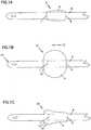
- FIG. 1Ashows a schematic view of a catheter in a deflated configuration 2 and illustrates how the balloon 4 is next to the catheter shaft 6.
- the balloon 4does not overlap either its distal end 7 or its proximal end 9.
- the balloon 4adds only a small increment to the diameter of the catheter shaft 6 because of how the uninflated balloon 4 lies flat over the catheter shaft 6.
- FIG. 1Bis a schematic view of a catheter in an inflated position 10 wherein the balloon 4 is cuffing.
- Cuffingrefers to the situation in which the balloon 4 tends to be shifted toward the bladder end 15 of the catheter (in the direction of arrow 12) forming a cuff 14, as the balloon 4 itself is pressed against the bladder wall when holding the catheter in place. Since the balloon 4 is attached at its distal end 7 to the shaft of the catheter 6, the balloon forms a cuff 14 as the outer expanded portion of the balloon 4 is pushed over the inner attached distal end 7 of the balloon 4.
- FIG. 1Cis a schematic view of a catheter in a deflated position 20 after having been inflated wherein the balloon has a cuff 14.
- the cuff 14results in the deflated balloon 4 having a larger diameter in an area 22 of the balloon 4 over the cuff 14 than it did when it was first inserted.
- a balloon that has cuffedmay be 12 French sizes larger at the cuff than the actual catheter shaft. The increased diameter can result in discomfort and injury to patients.
- an inner layeris formed over the shaft just in the area of the balloon.
- an outer layeris formed over the entire length of the shaft by dipping it in silicone balloon compound.
- the difference between the diameter of the balloon area and the diameter of the catheter shaft in the finished productcan be controlled simply by adjusting the thickness of the inner layer.
- the outer layercovers the entire length of the shaft. Therefore, the balloon area can be thickened by adding to the outer layer while not affecting the relative difference in diameters between the balloon area and the catheter shaft. While not intending to be bound by theory, it is believed that the added thickness in the balloon area results in a silicone rubber balloon that resists cuffing.
- the effective diameter of the shaft area and the diameter of the balloon areaare increased commensurately so that the differential between the shaft diameter and balloon diameter can be kept to an advantageous small amount, for example, about 4 French sizes (e.g., 1.33 mm / 0.052 inch) or less than or equal to 4 French sizes (1.33 mm / 0.052 inch).
- the approach of covering the entire catheter shaft with balloon compoundcan also result in a softer and therefore more comfortable shaft as a balloon compound can be used for the outer layer that has a durometer rating of approximately 20 when cured in contrast to the double lumen tube itself which has a durometer rating of approximately 65. Moreover, this approach can result in a stronger balloon that is less likely to burst.
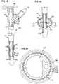
- FIG. 2a partial cut-away view of a portion of a Foley catheter is shown in accordance with an embodiment of the present invention.
- the catheterhas a finished balloon catheter shaft 104 and a fluid conduit access opening 156 in an exterior surface 162 of the catheter shaft 104.
- the balloon portion 158includes sections of two layers including the balloon layer 142 and the sheath layer 144.
- the balloon cavity 154is disposed under the balloon layer 142 and is in fluid communication with a capillary lumen 106 via a capillary lumen access opening 112.
- the Foley catheteralso includes a fluid conduit lumen 108.
- the balloon layeris an integral part of the catheter.
- a balloon layer that is an integral part of the cathetercan be formed by the dipping and stripping methods described herein.
- a balloon layer that is formed from cured material that is applied in cured form to a mandrel or shafte.g., as a preformed sleeve or as a tape wound around the shaft
- the balloonis formed with ribs made of a compound different from the balloon itself.
- the compound of the ribsstretches less easily than the compound of the balloon and results in a balloon that resists cuffing.
- the ribsfit in corresponding grooves in the main shaft of the catheter so that when the balloon is deflated it does not add to the outside diameter of the balloon.
- FIG. 3shows a cross-sectional view of an embodiment of the invention formed with ribs made of a compound different from the balloon itself.
- a double lumen tube 102includes a capillary lumen 106 and a fluid conduit lumen 108.
- the double lumen tube 102has undulations or channels 115 on its exterior surface.
- a balloon layer 142, surrounding the double lumen tube 102,includes a first region 141 and a second region 143.
- the first region 141includes ribs 160 including a less pliable silicone rubber than the silicone rubber of the second region 143. When the balloon is in a deflated position, the ribs 160 can fit in the undulations or channels 115.
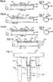
- the first step in making a balloon catheter in accordance with the present inventionis providing a double lumen tube 102, which is typically extruded.
- the double lumen tubecan be made by any known process which yields a double lumen tube.
- the double lumen tube 102includes a smaller capillary lumen 106 and a larger fluid conduit lumen 108.
- the tubeincludes a resilient polymeric material.
- the polymeric materialis a biocompatible polymeric material that can be inserted into a human body cavity.
- the tubeincludes silicone rubber.
- a capillary lumen access opening 112is created in an outer surface 114 of the double lumen tube 102.
- the capillary lumen access opening 112communicates with the capillary lumen 106.
- an intermediate tube 103is subsequently prepared from the double lumen tube 102 shown in FIG. 6 .
- a measured amount of a polymeric bonding compositionsuch as silicone rubber or another suitable polymeric bonding material, is injected into the capillary lumen 106 from the distal end 116 of the double lumen tube 102, so that the capillary lumen 106 is filled with a polymeric fill material 118 up to a point just below the capillary lumen access opening 112.
- a tip 120such as a rounded silicone rubber tip, can then be affixed to the distal end 116 of the tube 102 to complete the formation of the intermediate tube 103 shown in FIG. 10 .
- the distal end 116 of the tube 102is inserted into a molding apparatus (not shown) designed to mold a tip 120 on the end of the tube 102.
- an embodiment of the process of the inventioninvolves securing a plurality of intermediate tubes 103, like the intermediate 103 shown in FIG. 10 , to a rack or pallet 124 as shown in FIG. 11 .
- the rack or pallet 124will include a plurality of support rods 126, each equipped with a retaining clip 128.
- the intermediate tubes 103are secured on the support rods 126 by engaging individual support rods 126 in the larger of the two lumens, called the fluid conduit lumen 108, and sliding the intermediate tubes 103 up over the support rods 126 until the proximal ends 130 of the intermediate tubes 103 abut against the base of the retaining clips 128 or the tip 120 of each of the intermediate tubes 103 fits snugly against the distal tip of each of the support rods 126.
- the intermediate tubes 103can be secured on the support rods 126 without the aid of the retaining clips 128. This is because extruded double lumen tubes 102 used to make the intermediate tubes 103 generally have a slight bend in one direction or another when they are hung. This results in a slight bend in the intermediate tubes 103 that permits the intermediate tube 103 to be secured on a support rod 126 without the aid of a clip 128.
- the pallet 124can be transferred from place to place, and the intermediate tubes 103 on the pallet 124 can be dipped in a series of baths prepared to accomplish a series of process steps.
- the intermediate tube 103is made entirely of silicone rubber and is secured upon a support rod 126 made of spring steel.
- the tip 120 and the fill material 118 of the intermediate tube 103 shown in FIG. 10can be of the same material (silicone rubber) as the double lumen tube 102. Therefore, the tip 120 and the fill material 118 can form integral portions of the intermediate tube 103, which is shown in FIGS. 12-17 as an integral polymeric unit made of a single material.
- the first step in the automated coating or dipping process of forming the balloon portion of the balloon catheter, after the intermediate tubes 103 are secured to the pallet 124,is to coat the intermediate tubes 103 with a bond preventing agent, such as a removable bond preventing agent.
- a bond preventing agentsuch as a removable bond preventing agent.
- thisis accomplished by dipping each of the tubes 103 on the pallet 124 simultaneously into a first dip tank containing a bath of a removable bond preventing agent, such as a material which forms a semi-solid film on surfaces when cooled on contact followed by an opportunity for drying.
- Such materialsinclude petroleum jelly or petrolatum, other oil base substances which form a semisolid upon cooling to room temperature, liquid soaps which dry to form a semi-solid, aqueous soap or detergent solutions, aqueous or oil based film forming solids emulsions, and the like.
- hot petrolatumis used, and in another, a liquid soap is used, such as LIQUID IVORY® soap from Proctor & Gamble, Cincinnati, Ohio.
- the agentadheres to the outer surface 114 of the intermediate tube 103, and enters the capillary lumen access opening 112 and runs up into the capillary lumen 106 (as shown in FIG. 13 ).
- the agentis petrolatum, which is heated to about 140°-160° F (60°-71° C). In an embodiment, the petrolatum is heated to about 150° F (65.6°C). At these temperatures, the petrolatum will run up into the capillary lumen 106 through the capillary lumen access opening 112 with the assistance of the "capillary effect", which draws the fluid into the capillary lumen 106 to the level of the petrolatum in the first tank.
- the bond preventing agent in the first tankis liquid soap at room temperature (about 62°-74°F / 16.7°- 23.3°C).
- the liquid soapforms of semi-solid just as the hot petrolatum did as it cooled.
- the tubes 103are then dipped in a series of dip tanks provided to remove the bond preventing agent from a portion 114a of the outer surface 114 below the line designated B. After this portion 114a of the outer surface 114 is substantially stripped of any residue of the bond preventing agent, the intermediate tubes 103, now partially coated with bond preventing agent between the lines designated A and B as shown in FIG. 15 , are dipped in a polymeric bonding composition, such as silicone rubber, in a step or steps provided to coat the intermediate tube 103. The catheter is dipped so that the silicone rubber covers up to line C as shown in FIG. 16 .
- a polymeric bonding compositionsuch as silicone rubber
- thiscan be about 0.25 inches above the top of the band 138 of bond preventing agent.
- a solventis used to remove deposited balloon compound below line D of FIG. 16 .
- Suitable solventscan include xylene or toluene. This deposition process can be repeated until the balloon area (balloon layer) is the desired diameter relative to the shaft of the catheter.
- the difference in diametersis less than or equal to about 4 French sizes (e.g., about 0.052 inch), for example, no more than 4 French sizes (0.052 inch / 1.33 mm).
- the silicone rubbercan be cured before further processing steps. Accordingly, in an embodiment, the silicone rubber including the balloon layer is cured before any further layers of silicone rubber are applied to the catheter. However, in other embodiments, curing can be delayed until later points in the processing steps.
- the whole length of the intermediate catheteris dipped into a solution of silicone rubber (such as Dow Corning C6-515 or another appropriate balloon compound) creating a second or sheath layer 144 (also known as a second overcoat layer).
- silicone rubbersuch as Dow Corning C6-515 or another appropriate balloon compound
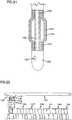
- the catheteris then dipped into a solution of thin finish-type silicone rubber (such as Dow Corning 4720) so that the finish-type silicone rubber covers the entire length of the catheter shaft and creates a finish layer 147 (as shown in FIG. 21 ).
- This finish layerprovides beneficial tactile properties to the exterior of the catheter.
- the proximal end 130 of the balloon catheter shaft 104is secured to an end piece 146 to form a completed Foley catheter 105 (shown in FIG. 18 ).
- the end piece 146can include a cap 148 for closing a proximal end access opening 149 to the fluid conduit lumen 108 and can be equipped with a luer valve 150 for engagement in and closure of the proximal capillary lumen access upper opening 152 communicating with the capillary lumen 106.
- the completed balloon catheter 104Prior to the attachment of the end piece 146 to the balloon catheter 104 to form the completed Foley catheter 105, the completed balloon catheter 104 is typically allowed to air dry to permit solvents in the first layer 142 (or balloon layer or first overcoat layer) and the second layer 144 (or sheath layer or second overcoat layer) to evaporate and is subsequently cured at an elevated temperature. Care is taken to keep the curing temperature below the boiling temperatures of the solvent so as to prevent unsightly bubbling of the solvent within the balloon layer 142 and the sheath layer 144.
- the completed Foley catheter 105also includes a fluid conduit access opening 156 in an exterior surface 162 of the completed Foley catheter 105. The fluid conduit access opening 156 communicates with the fluid conduit lumen 108.
- the end piece 146is made by a process of injection molding.
- the proximal end 130 of the balloon catheter shaft 104is inserted into the injection molding apparatus after the sheath layer 144 has been cured.
- the polymeric bonding compositionsuch as silicone rubber, is then injected into the mold (not shown) and the end piece 146 is molded onto the proximal end 130 of the balloon catheter shaft 104 to make the completed Foley catheter 105 shown in FIG. 18 .
- the balloon portion 158 of the balloon layer 142 and the sheath layer 144is the portion that is not bonded to the outer surface 114 of the intermediate tube 103.
- the balloon portion 158 of the balloon layer 142 and the sheath layer 144cooperates with the portion 114c of the outer surface 114 which remained coated with the bond preventing agent prior to the step of dipping the intermediate tube 103 in the polymeric bonding composition, to define a balloon cavity 154.
- the balloon cavity 154communicates with the capillary lumen 106 via the capillary lumen access opening 112. When a fluid is pumped or injected into the capillary access lumen 106, the balloon portion 158 and the balloon cavity 154 are expanded.
- the bond preventing agentcan be removed from the balloon lumen 154 and the capillary lumen 106 by using a hot aqueous solution.
- any of variety of known testscan be used to ensure that there are no leaks in the balloon portion 158 of the finished catheters 105.
- the catheters 105 that have passed all testsare then packaged, such as in a material which breathes such as Tyvek® (from DuPont), and boxed.
- the boxescan then be sterilized with ETO (Ethylene Oxide) and then stored for shipment.
- ribsare formed in the balloon portion 158 of the catheter.
- the extruded double lumen tube 102 used to make the intermediate tube 103is a tube which has a series of generally parallel undulations or channels running generally parallel with the longitudinal axis of the tube 103.
- a Foley catheter having ribs 160 on the inner surface on the balloon portion of the completed Foley catheterwill result because the bond preventing coating 138 on the intermediate tube will reciprocate the undulations 115 in the ribbed outer surface 114 of the intermediate tube 103.
- Embodiments of the catheter made with ribsmay or may not have the layer of balloon type silicone rubber coating the entire length of the catheter shaft as described above.
- the catheterincludes both the layer of silicone rubber (or sheath layer) covering the entire catheter shaft and the ribs in the balloon layer.
- the ribsare made of a silicone rubber having different properties than the silicone rubber used for the rest of the balloon.
- the silicone rubber used to make the ribscan be less pliable than the silicone rubber used to make the rest of the balloon. While not intending to be bound by theory, it is thought that by creating such ribs in the balloon in a direction parallel to the catheter shaft that the stretching of the balloon in that direction is limited resulting in a balloon that resisting cuffing. Referring now to FIG.
- a less pliable silicone rubberis used directly over the bond preventing coating 138, so that an inner region 141 which includes the ribs 160 is first formed, then the rest of the inner layer is formed with regular balloon compound so that the balloon layer 142 also includes a second region 143 of silicone rubber.
- balloon fabricationcan be almost completely automated. Entire sets of balloon catheters 104 are manufactured simultaneously.
- the pallet 124has 400 spring steel support rods 126 attached to a pallet in 20 rows of 20 rods, wherein each of the rods 126 is about 1 inch from each adjacent rod.
- Double lumen tubing(not shown) can be made by an extrusion process which is known to those of skill in the art.
- the tubes 102are cut to length as the tubing leaves the extruder (not shown).
- An opening 112is created in the outer surface 114, such as with a hollow drill bit or tube (not shown), so as to communicate with the capillary lumen 106.
- the distal portion 106a of the capillary lumen 106located between the distal end 116 of the tube 102 and the capillary lumen access opening 112, is injected with a measured amount of a polymeric bonding composition, such as silicone rubber, so that the distal portion 106a is filled and sealed.
- a rounded tip 120can be formed at the distal end 116 of the double lumen tube 102 by inserting the tube 102 in a molding device (not shown).
- 400 of the intermediate tubes 103are then mounted vertically on rigid spring steel support rods 126 on a pallet 124 in the manner previously described.
- the pallet 124is then moved via a transporting mechanism 122 (see FIG. 22 ) over a series of dip tanks as follows in one of these embodiments:
- the phrase "adapted and configured”describes a system, apparatus, or other structure that is constructed or configured to perform a particular task or adopt a particular configuration to.
- the phrase "adapted and configured”can be used interchangeably with other similar phrases such as arranged and configured, constructed and arranged, adapted, constructed, manufactured and arranged, and the like.
Landscapes
- Health & Medical Sciences (AREA)
- Life Sciences & Earth Sciences (AREA)
- Heart & Thoracic Surgery (AREA)
- Biomedical Technology (AREA)
- Animal Behavior & Ethology (AREA)
- Pulmonology (AREA)
- Engineering & Computer Science (AREA)
- Anesthesiology (AREA)
- Veterinary Medicine (AREA)
- Hematology (AREA)
- Biophysics (AREA)
- General Health & Medical Sciences (AREA)
- Public Health (AREA)
- Child & Adolescent Psychology (AREA)
- Epidemiology (AREA)
- Urology & Nephrology (AREA)
- Media Introduction/Drainage Providing Device (AREA)
- Materials For Medical Uses (AREA)
Description
- The invention relates to a Foley-type catheter constructed to reduce or eliminate the retention balloon from cuffing. More particularly, in certain embodiments, the invention relates to a catheter Including a sheath layer over the outside surface of the catheter, and to methods of making and using such a catheter. In an embodiment, the invention relates to a catheter with a retention balloon including ribs.
- Foley-type catheters are tube like devices that are used to drain urine from a patient's bladder. Foley catheters are inserted through the urethra and typically held in place with an Inflatable balloon. The balloon is in a deflated position when the catheter is first inserted. Then, once the catheter is in the proper position, the balloon is inflated with a fluid. The inflated balloon is larger than the diameter of the urethra and thereby physically prevents the catheter from being removed. Foley catheters are also known as "indwelling" catheters because they are designed to be left in place for a period of time.
- Latex rubber is commonly used for Foley catheters. However, latex rubber can be problematic as many patients have latex allergies. Silicone rubber has been used to make Foley catheters since it does not cause the same problems with irritation as does latex rubber. However, silicone rubber does not have the same elastic properties as latex rubber. As a result, the balloons on Foley catheters that are made with silicone rubber can exhibit "cuffing."
- Cuffing refers to the situation in which the balloon tends to be shifted toward the bladder end of the catheter as the balloon itself is pressed against the bladder wall when holding the catheter in place. Since the balloon is attached at its end to the shaft of the catheter, the balloon can form a cuff as the outer expanded portion of the balloon is pushed over the inner attached end of the balloon. This cuff can remain when the balloon is deflated before withdrawal of the catheter from the patient. The cuff results in the deflated balloon having a larger diameter than it did when it was first inserted. The increased diameter can result in discomfort and injury to patients. Accordingly, a need exists for a silicone rubber Foley catheter that resists cuffing.
US5599321 provides a catheter according to the pre-characterizing part of claim 1.WO95/09667 USS409495 andUS2002/0032406 provide examples of other catheter designs.- The invention relates to a Foley-type catheter constructed to reduce or eliminate retention balloon cuffing. More particularly, in certain embodiments, the invention relates to a catheter including a sheath layer over the outside surface of the catheter and to methods of making such a catheter.
- According to a first aspect the invention provides a catheter comprising:
- a central layer providing a catheter shaft and having a catheter tip, an exterior surface and an interior surface and defining a first lumen and a second lumen;
- a balloon layer surrounding the central layer, the balloon layer including a balloon portion, the balloon portion being the portion which is not bonded to the exterior surface of the central layer; the balloon portion being in the form of a cavity disposed between the exterior surface of the central layer and the balloon layer;
- wherein the balloon cavity is in fluid communication with the second lumen;
- wherein the balloon layer and the central layer are joined together at a distal end and at a proximal end of the balloon cavity relative to the catheter tip; and
- a sheath layer surrounding the balloon layer and extending at least over the balloon layer;
characterized in that, the balloon layer Is provided on the catheter shaft just in the area of the balloon portion and the sheath layer is provided on the catheter shaft over the entire length of the catheter shaft and the balloon layer does not cover the entire length of the catheter shaft to be inserted into the patient. - In an embodiment, the invention may further provide a catheter with a retention balloon including ribs.
- In the drawings, in which like reference numerals indicate corresponding parts throughout the several views,
FIG. 1A is a schematic view of a catheter is an original deflated configuration;FIG. 1B is a schematic view of a catheter in an inflated position wherein the balloon is cuffing;FIG. 1C is a schematic view of a catheter in a deflated position wherein the balloon has retained a cuff;FIG. 2 is a partial cut-away view of a portion of a Foley catheter made in accordance with an embodiment of the present invention;FIG. 3 shows a cross-sectional view of an embodiment of the invention formed with ribs made of a compound different from the balloon itself;FIG. 4 is a partial cut-away view of an extruded double lumen tube in partial cross-section;FIG. 5 is a cross-sectional view of the extruded double lumen tube as seen from the line 202-202' ofFIG. 4 ;FIG. 6 is a partial cut-away view of the tube shown inFIG. 4 after an opening is punched in the outer surface;FIG. 7 is a cross-sectional view of the tube as shown from the line 204-204' ofFIG. 6 ;FIG. 8 is a partial cut-away view of the double lumen tube shown inFIG. 6 after a portion of the first lumen has been filled with a polymeric bonding composition;FIG. 9 is a cross-sectional view of the tube as seen from the line 206-206' ofFIG. 8 ;FIG. 10 is a partial cut-away view of the double lumen tube shown inFIG. 8 after a tip is affixed to a distal end of the tube;FIG. 11 is a schematic view of a portion of a rack used to retain a plurality of tubes during a series of steps designed to provide the tube with an overcoat layer of a polymeric bonding composition;FIG. 12 is a partial cut-away view of an intermediate tube similar to the tube shown inFIG. 10 at an intermediate stage of manufacture prior to the first of a series of dipping steps;FIG. 13 is a partial cut-away view of an intermediate tube similar to that shown inFIG. 12 , but following a first dipping step wherein the outer surface is coated with a bond preventing agent up to the point designated by line A;FIG. 14 is a cross-sectional view of the intermediate tube ofFIG. 13 as shown from the line 211-211';FIG. 15 is a partial cut-away view of an intermediate tube similar to that shown inFIG. 13 , but after a subsequent dipping step or steps in which the coating of bond preventing agent on a portion of the outer surface of the intermediate tube has been removed;FIG. 16 is a partial cut-away view of an intermediate tube similar to that shown inFIG. 15 , but after subsequent steps in which a balloon compound has been deposited both slightly above and below the bond preventing agent;FIG. 17 is a partial cut-away view of an intermediate tube similar to that shown inFIG. 16 , but after a step of dipping the entire length of the catheter shaft in a balloon compound;FIG. 18 is a partial cut-away view of a Foley catheter made in accordance with the present invention following testing and cleaning and showing cut-away views of portions thereof;FIG. 19 is a partial cut-away view of a portion of the Foley catheter shown inFIG. 18 , but with the balloon portion of the catheter shown when expanded;FIG. 20 is a cross-sectional view of a Foley catheter made in accordance with the present invention showing ribs formed in the balloon portion of the catheter;FIG. 21 is a partial cut-away view of a portion of an embodiment of a Foley catheter with a finish layer.FIG. 22 is a schematic illustration of an apparatus used to automate the production of balloon catheters in accordance with the present invention.- While the invention is susceptible to various modifications and alternative forms, specifics thereof have been shown by way of example and drawings, and will be described in detail. It should be understood, however, that the invention is not limited to the particular embodiments described. On the contrary, the intention is to cover modifications, equivalents, and alternatives falling within the spirit and scope of the invention.
- As described above, balloon catheters made with silicone rubber can exhibit problematic cuffing.
FIG. 1A shows a schematic view of a catheter in a deflatedconfiguration 2 and illustrates how theballoon 4 is next to thecatheter shaft 6. In this configuration, theballoon 4 does not overlap either itsdistal end 7 or itsproximal end 9. Further, in the configuration shown inFIG. 1A , theballoon 4 adds only a small increment to the diameter of thecatheter shaft 6 because of how theuninflated balloon 4 lies flat over thecatheter shaft 6. - However, as described above, balloon catheters made with silicone rubber may exhibit problems with cuffing.
FIG. 1B is a schematic view of a catheter in aninflated position 10 wherein theballoon 4 is cuffing. Cuffing refers to the situation in which theballoon 4 tends to be shifted toward thebladder end 15 of the catheter (in the direction of arrow 12) forming acuff 14, as theballoon 4 itself is pressed against the bladder wall when holding the catheter in place. Since theballoon 4 is attached at itsdistal end 7 to the shaft of thecatheter 6, the balloon forms acuff 14 as the outer expanded portion of theballoon 4 is pushed over the inner attacheddistal end 7 of theballoon 4. - The
cuff 14 that is formed tends to remain when theballoon 4 is deflated before withdrawal of the catheter from the patient.FIG. 1C is a schematic view of a catheter in a deflatedposition 20 after having been inflated wherein the balloon has acuff 14. Thecuff 14 results in the deflatedballoon 4 having a larger diameter in anarea 22 of theballoon 4 over thecuff 14 than it did when it was first inserted. For example, a balloon that has cuffed may be 12 French sizes larger at the cuff than the actual catheter shaft. The increased diameter can result in discomfort and injury to patients. - The present inventors have created embodiments of catheters that can resist cuffing. In an embodiment of the invention, an inner layer is formed over the shaft just in the area of the balloon. Then an outer layer is formed over the entire length of the shaft by dipping it in silicone balloon compound. In this manner, the difference between the diameter of the balloon area and the diameter of the catheter shaft in the finished product can be controlled simply by adjusting the thickness of the inner layer. This is because in contrast to the inner layer, the outer layer covers the entire length of the shaft. Therefore, the balloon area can be thickened by adding to the outer layer while not affecting the relative difference in diameters between the balloon area and the catheter shaft. While not intending to be bound by theory, it is believed that the added thickness in the balloon area results in a silicone rubber balloon that resists cuffing.
- In certain embodiments, the effective diameter of the shaft area and the diameter of the balloon area are increased commensurately so that the differential between the shaft diameter and balloon diameter can be kept to an advantageous small amount, for example, about 4 French sizes (e.g., 1.33 mm / 0.052 inch) or less than or equal to 4 French sizes (1.33 mm / 0.052 inch).
- The approach of covering the entire catheter shaft with balloon compound can also result in a softer and therefore more comfortable shaft as a balloon compound can be used for the outer layer that has a durometer rating of approximately 20 when cured in contrast to the double lumen tube itself which has a durometer rating of approximately 65. Moreover, this approach can result in a stronger balloon that is less likely to burst.
- Referring to
FIG. 2 , a partial cut-away view of a portion of a Foley catheter is shown in accordance with an embodiment of the present invention. The catheter has a finishedballoon catheter shaft 104 and a fluid conduit access opening 156 in anexterior surface 162 of thecatheter shaft 104. Theballoon portion 158 includes sections of two layers including theballoon layer 142 and thesheath layer 144. Theballoon cavity 154 is disposed under theballoon layer 142 and is in fluid communication with acapillary lumen 106 via a capillarylumen access opening 112. The Foley catheter also includes afluid conduit lumen 108. - In an embodiment, the balloon layer is an integral part of the catheter. For example, a balloon layer that is an integral part of the catheter can be formed by the dipping and stripping methods described herein. For example, a balloon layer that is formed from cured material that is applied in cured form to a mandrel or shaft (e.g., as a preformed sleeve or as a tape wound around the shaft) is not an integral part of the catheter.
- In an embodiment of the invention, the balloon is formed with ribs made of a compound different from the balloon itself. The compound of the ribs stretches less easily than the compound of the balloon and results in a balloon that resists cuffing. In an embodiment, the ribs fit in corresponding grooves in the main shaft of the catheter so that when the balloon is deflated it does not add to the outside diameter of the balloon.
FIG. 3 shows a cross-sectional view of an embodiment of the invention formed with ribs made of a compound different from the balloon itself. Adouble lumen tube 102 includes acapillary lumen 106 and afluid conduit lumen 108. Thedouble lumen tube 102 has undulations orchannels 115 on its exterior surface. Aballoon layer 142, surrounding thedouble lumen tube 102, includes afirst region 141 and asecond region 143. Thefirst region 141 includesribs 160 including a less pliable silicone rubber than the silicone rubber of thesecond region 143. When the balloon is in a deflated position, theribs 160 can fit in the undulations orchannels 115.- Referring now to the drawings, and specifically to
FIGS. 4 and 5 , the first step in making a balloon catheter in accordance with the present invention is providing adouble lumen tube 102, which is typically extruded. However, the double lumen tube can be made by any known process which yields a double lumen tube. Thedouble lumen tube 102 includes asmaller capillary lumen 106 and a largerfluid conduit lumen 108. The tube includes a resilient polymeric material. In an embodiment, the polymeric material is a biocompatible polymeric material that can be inserted into a human body cavity. In a particular embodiment, the tube includes silicone rubber. - Referring now also to
FIGS. 6 and 7 , after the double lumen tube is cut to a desired size, a capillary lumen access opening 112 is created in anouter surface 114 of thedouble lumen tube 102. The capillary lumen access opening 112 communicates with thecapillary lumen 106. - Referring now to
FIGS. 8-10 , anintermediate tube 103 is subsequently prepared from thedouble lumen tube 102 shown inFIG. 6 . In the first step of this process, a measured amount of a polymeric bonding composition, such as silicone rubber or another suitable polymeric bonding material, is injected into thecapillary lumen 106 from thedistal end 116 of thedouble lumen tube 102, so that thecapillary lumen 106 is filled with apolymeric fill material 118 up to a point just below the capillarylumen access opening 112. Atip 120, such as a rounded silicone rubber tip, can then be affixed to thedistal end 116 of thetube 102 to complete the formation of theintermediate tube 103 shown inFIG. 10 . In a method of the invention, thedistal end 116 of thetube 102 is inserted into a molding apparatus (not shown) designed to mold atip 120 on the end of thetube 102. - Referring now also to
FIGS. 10-17 , an embodiment of the process of the invention involves securing a plurality ofintermediate tubes 103, like the intermediate 103 shown inFIG. 10 , to a rack orpallet 124 as shown inFIG. 11 . The rack orpallet 124 will include a plurality ofsupport rods 126, each equipped with a retainingclip 128. Theintermediate tubes 103 are secured on thesupport rods 126 by engagingindividual support rods 126 in the larger of the two lumens, called thefluid conduit lumen 108, and sliding theintermediate tubes 103 up over thesupport rods 126 until the proximal ends 130 of theintermediate tubes 103 abut against the base of the retainingclips 128 or thetip 120 of each of theintermediate tubes 103 fits snugly against the distal tip of each of thesupport rods 126. Although not shown, it is believed that theintermediate tubes 103 can be secured on thesupport rods 126 without the aid of the retaining clips 128. This is because extrudeddouble lumen tubes 102 used to make theintermediate tubes 103 generally have a slight bend in one direction or another when they are hung. This results in a slight bend in theintermediate tubes 103 that permits theintermediate tube 103 to be secured on asupport rod 126 without the aid of aclip 128. - When the
intermediate tubes 103 have been secured on thesupport rods 126, thepallet 124 can be transferred from place to place, and theintermediate tubes 103 on thepallet 124 can be dipped in a series of baths prepared to accomplish a series of process steps. In an embodiment of the method of the invention, theintermediate tube 103 is made entirely of silicone rubber and is secured upon asupport rod 126 made of spring steel. Thetip 120 and thefill material 118 of theintermediate tube 103 shown inFIG. 10 can be of the same material (silicone rubber) as thedouble lumen tube 102. Therefore, thetip 120 and thefill material 118 can form integral portions of theintermediate tube 103, which is shown inFIGS. 12-17 as an integral polymeric unit made of a single material. - The first step in the automated coating or dipping process of forming the balloon portion of the balloon catheter, after the
intermediate tubes 103 are secured to thepallet 124, is to coat theintermediate tubes 103 with a bond preventing agent, such as a removable bond preventing agent. In an embodiment, this is accomplished by dipping each of thetubes 103 on thepallet 124 simultaneously into a first dip tank containing a bath of a removable bond preventing agent, such as a material which forms a semi-solid film on surfaces when cooled on contact followed by an opportunity for drying. Examples of such materials include petroleum jelly or petrolatum, other oil base substances which form a semisolid upon cooling to room temperature, liquid soaps which dry to form a semi-solid, aqueous soap or detergent solutions, aqueous or oil based film forming solids emulsions, and the like. In one embodiment described herein, hot petrolatum is used, and in another, a liquid soap is used, such as LIQUID IVORY® soap from Proctor & Gamble, Cincinnati, Ohio. - When the
intermediate tubes 103 are removed from this first bath of removable bond preventing agent, the agent adheres to theouter surface 114 of theintermediate tube 103, and enters the capillary lumen access opening 112 and runs up into the capillary lumen 106 (as shown inFIG. 13 ). In one embodiment the agent is petrolatum, which is heated to about 140°-160° F (60°-71° C). In an embodiment, the petrolatum is heated to about 150° F (65.6°C). At these temperatures, the petrolatum will run up into thecapillary lumen 106 through the capillary lumen access opening 112 with the assistance of the "capillary effect", which draws the fluid into thecapillary lumen 106 to the level of the petrolatum in the first tank. As theintermediate tubes 103 are withdrawn from the hot petrolatum, petrolatum on each tube cools and solidifies to form asemi-solid coating 138 on theouter surface 114 and a semi-solid filling 134 in thecapillary lumen 106 and the capillary lumen access opening 112 which cooperate to plug the capillarylumen access opening 112. In an alternate embodiment, the bond preventing agent in the first tank is liquid soap at room temperature (about 62°-74°F / 16.7°- 23.3°C). When thetubes 103 are withdrawn from the first dip tank, the liquid soap forms of semi-solid just as the hot petrolatum did as it cooled. Although both of these bond preventing agents are effective, there is some advantage to using the soap because it does not require the added expense for heating. Furthermore, in certain embodiments, soap is easier to remove from thecapillary lumen 106 and the balloon cavity 154 (as shown inFIG. 18 ). - After the
intermediate tubes 103 are coated and the capillarylumen access openings 112 are plugged with bond preventing agent in this manner, thetubes 103 are then dipped in a series of dip tanks provided to remove the bond preventing agent from aportion 114a of theouter surface 114 below the line designated B. After thisportion 114a of theouter surface 114 is substantially stripped of any residue of the bond preventing agent, theintermediate tubes 103, now partially coated with bond preventing agent between the lines designated A and B as shown inFIG. 15 , are dipped in a polymeric bonding composition, such as silicone rubber, in a step or steps provided to coat theintermediate tube 103. The catheter is dipped so that the silicone rubber covers up to line C as shown inFIG. 16 . In some embodiments this can be about 0.25 inches above the top of theband 138 of bond preventing agent. Then a solvent is used to remove deposited balloon compound below line D ofFIG. 16 . Suitable solvents can include xylene or toluene. This deposition process can be repeated until the balloon area (balloon layer) is the desired diameter relative to the shaft of the catheter. In an embodiment the difference in diameters is less than or equal to about 4 French sizes (e.g., about 0.052 inch), for example, no more than 4 French sizes (0.052 inch / 1.33 mm). - After a desired amount of silicone rubber is deposited in the balloon layer, the silicone rubber can be cured before further processing steps. Accordingly, in an embodiment, the silicone rubber including the balloon layer is cured before any further layers of silicone rubber are applied to the catheter. However, in other embodiments, curing can be delayed until later points in the processing steps.
- Then the whole length of the intermediate catheter is dipped into a solution of silicone rubber (such as Dow Corning C6-515 or another appropriate balloon compound) creating a second or sheath layer 144 (also known as a second overcoat layer). By applying silicone rubber to the entire length of the shaft, the balloon is thickened but the difference in thickness between the balloon and the shaft is maintained. Optionally, the catheter is then dipped into a solution of thin finish-type silicone rubber (such as Dow Corning 4720) so that the finish-type silicone rubber covers the entire length of the catheter shaft and creates a finish layer 147 (as shown in
FIG. 21 ). This finish layer provides beneficial tactile properties to the exterior of the catheter. - In subsequent steps, the
proximal end 130 of theballoon catheter shaft 104 is secured to anend piece 146 to form a completed Foley catheter 105 (shown inFIG. 18 ). Theend piece 146 can include acap 148 for closing a proximal end access opening 149 to thefluid conduit lumen 108 and can be equipped with aluer valve 150 for engagement in and closure of the proximal capillary lumen accessupper opening 152 communicating with thecapillary lumen 106. Prior to the attachment of theend piece 146 to theballoon catheter 104 to form the completedFoley catheter 105, the completedballoon catheter 104 is typically allowed to air dry to permit solvents in the first layer 142 (or balloon layer or first overcoat layer) and the second layer 144 (or sheath layer or second overcoat layer) to evaporate and is subsequently cured at an elevated temperature. Care is taken to keep the curing temperature below the boiling temperatures of the solvent so as to prevent unsightly bubbling of the solvent within theballoon layer 142 and thesheath layer 144. The completedFoley catheter 105 also includes a fluid conduit access opening 156 in anexterior surface 162 of the completedFoley catheter 105. The fluid conduit access opening 156 communicates with thefluid conduit lumen 108. - In an embodiment of the present invention, the
end piece 146 is made by a process of injection molding. Typically, theproximal end 130 of theballoon catheter shaft 104 is inserted into the injection molding apparatus after thesheath layer 144 has been cured. The polymeric bonding composition, such as silicone rubber, is then injected into the mold (not shown) and theend piece 146 is molded onto theproximal end 130 of theballoon catheter shaft 104 to make the completedFoley catheter 105 shown inFIG. 18 . - The
balloon portion 158 of theballoon layer 142 and thesheath layer 144 is the portion that is not bonded to theouter surface 114 of theintermediate tube 103. Theballoon portion 158 of theballoon layer 142 and thesheath layer 144 cooperates with theportion 114c of theouter surface 114 which remained coated with the bond preventing agent prior to the step of dipping theintermediate tube 103 in the polymeric bonding composition, to define aballoon cavity 154. Theballoon cavity 154 communicates with thecapillary lumen 106 via the capillarylumen access opening 112. When a fluid is pumped or injected into thecapillary access lumen 106, theballoon portion 158 and theballoon cavity 154 are expanded. The bond preventing agent can be removed from theballoon lumen 154 and thecapillary lumen 106 by using a hot aqueous solution. - Any of variety of known tests can be used to ensure that there are no leaks in the
balloon portion 158 of thefinished catheters 105. After testing is completed, thecatheters 105 that have passed all tests, are then packaged, such as in a material which breathes such as Tyvek® (from DuPont), and boxed. The boxes can then be sterilized with ETO (Ethylene Oxide) and then stored for shipment. - In an embodiment of the present invention, ribs are formed in the
balloon portion 158 of the catheter. For this embodiment, the extrudeddouble lumen tube 102 used to make theintermediate tube 103 is a tube which has a series of generally parallel undulations or channels running generally parallel with the longitudinal axis of thetube 103. When such a tube is used, a Foleycatheter having ribs 160 on the inner surface on the balloon portion of the completed Foley catheter will result because thebond preventing coating 138 on the intermediate tube will reciprocate theundulations 115 in the ribbedouter surface 114 of theintermediate tube 103. Embodiments of the catheter made with ribs may or may not have the layer of balloon type silicone rubber coating the entire length of the catheter shaft as described above. As the ribs can serve to prevent cuffing, the extra thickness provided by the additional layer of silicone may be unnecessary depending on the application. Therefore, in some embodiments, the catheter includes both the layer of silicone rubber (or sheath layer) covering the entire catheter shaft and the ribs in the balloon layer. - In some embodiments, the ribs are made of a silicone rubber having different properties than the silicone rubber used for the rest of the balloon. For example, the silicone rubber used to make the ribs can be less pliable than the silicone rubber used to make the rest of the balloon. While not intending to be bound by theory, it is thought that by creating such ribs in the balloon in a direction parallel to the catheter shaft that the stretching of the balloon in that direction is limited resulting in a balloon that resisting cuffing. Referring now to
FIG. 20 , when making theballoon layer 142, a less pliable silicone rubber is used directly over thebond preventing coating 138, so that aninner region 141 which includes theribs 160 is first formed, then the rest of the inner layer is formed with regular balloon compound so that theballoon layer 142 also includes asecond region 143 of silicone rubber. - In the Applicants' use of the methods of the present invention, balloon fabrication can be almost completely automated. Entire sets of
balloon catheters 104 are manufactured simultaneously. Thepallet 124 has 400 springsteel support rods 126 attached to a pallet in 20 rows of 20 rods, wherein each of therods 126 is about 1 inch from each adjacent rod. Double lumen tubing (not shown) can be made by an extrusion process which is known to those of skill in the art. Thetubes 102 are cut to length as the tubing leaves the extruder (not shown). Anopening 112 is created in theouter surface 114, such as with a hollow drill bit or tube (not shown), so as to communicate with thecapillary lumen 106. Thedistal portion 106a of thecapillary lumen 106, located between thedistal end 116 of thetube 102 and the capillary lumen access opening 112, is injected with a measured amount of a polymeric bonding composition, such as silicone rubber, so that thedistal portion 106a is filled and sealed. Arounded tip 120 can be formed at thedistal end 116 of thedouble lumen tube 102 by inserting thetube 102 in a molding device (not shown). - In some embodiments of the present method, 400 of the
intermediate tubes 103 are then mounted vertically on rigid springsteel support rods 126 on apallet 124 in the manner previously described. Thepallet 124 is then moved via a transporting mechanism 122 (seeFIG. 22 ) over a series of dip tanks as follows in one of these embodiments: - (A) The
pallet 124 is stopped over afirst tank 133, which contains white USP petrolatum heated to about 67° C (about 150° F). The tank is raised so as to immerse theintermediate tubes 103 into the petrolatum to such a depth that the petrolatum reaches the proximal end of the desired balloon location. Thedip tank 133 is then lowered and a portion of theouter surface 114 of theintermediate tubes 103 are coated with petrolatum. This portion extends from the point at which the proximal end of theballoon portion 158 will begin to the distal end of thetip 120 of theintermediate tube 103. An intermediate tube after this step is as shown inFIG. 13 . - (B) The
pallet 124 is then automatically advanced and stopped over asecond dip tank 135 which contains white USP petrolatum heated to about 120° C (about 250° F). Thesecond dip tank 135 is raised so as to immerse theintermediate tubes 103 into the super-heated petrolatum so that the super-heated petrolatum comes into contact with the petrolatum coating onouter surface 114 of theintermediate tube 103 from the prior dipping step up to a location where a distal end of theballoon portion 158 will end. Thesecond dip tank 135 is then lowered. This dipping step causes the coating of petrolatum from the prior dipping step to be largely removed from aportion 114a of theouter surface 114 of theintermediate tube 103 from a location where the distal end of theballoon lumen 154 will be located (designated by line B) to thedistal end 120a of thetip 120 of theintermediate tube 103. Some residual petrolatum may remain on theouter surface 114 of theintermediate tube 103 in thisportion 114a of theouter surface 114. However, most of the petrolatum is removed. - (C) The
pallet 124 is then automatically advanced and stopped over athird dip tank 137 containing mineral spirits heated to about 200° F. Thethird dip tank 137 is then raised so as to immerse theintermediate tubes 103 into the mineral spirits to the same depth as they were immersed in the super-heated petrolatum in thesecond dip tank 135. Thetank 137 is then lowered and all but a trace amount of the petrolatum is removed from theportion 114a of theouter surface 114 below theportion 114c of theouter surface 114, which will eventually be proximate theballoon lumen 154. - (D) The
pallet 124 is then automatically advanced and stopped over afourth dip tank 139 containing a volatile organic solvent such as toluene, trichloroethane or the like. Thefourth tank 139 is then raised to immerse theintermediate catheters 103 to the same depth as previously immersed in the second andthird tanks portion 114a of theouter surface 114. Theintermediate catheter tube 103 now has aband 138 of semi-solid petrolatum located around the axial circumference of theintermediate tube 103 in the location where theballoon cavity 154 will be created. The petrolatum not only coats theportion 114c of theouter surface 114 located in this area, but also fills a portion of thecapillary lumen 106 and plugs the capillary lumen access opening 112, which will eventually be used to inflate theballoon portion 158 of the completedFoley catheter 105. An intermediate tube after this step is as shown inFIG. 15 . - (E) The
pallet 124 is then lowered and automatically advanced to afifth dip tank 141 containing a heptane dispersed solution of silicone rubber (such as Dow Corning C6-515 or another appropriate balloon compound). Thefifth tank 141 is then raised so that the balloon compound covers the balloon area. In some embodiments this can be about 0.25 inches above the top of theband 138 of bond preventing agent.
Optionally, where it is desired to create ribs on the interior of the balloon that are of a less pliable silicone rubber than the rest of the balloon, the first time of performing step (E) is done by using a dip tank filled with a dispersed solution of silicone rubber that is less pliable than the standard balloon compound used. For example, a higher modulus silicone such as a 50/50 mixture of Dow Corning Q7-4850 and Dow Corning Q7-4720 can be used for initial dips. Thereafter, when step (E) is repeated, the normal balloon compound is used. This results in a balloon with ribs wherein the ribs are less pliable than the rest of the balloon. - (F) The
pallet 124 is then advanced to asixth dip tank 143 containing a solvent effective to remove deposited balloon compound. Suitable solvents include xylene or toluene. Thesixth tank 143 is then raised so that the solvent removes the balloon compound below the balloon area. In some embodiments, this can be about 0.25 inches below the top of theband 138 of bond preventing agent. At this point the pallet can be air dried to remove solvents for approximately 30 minutes. Then steps (E) and (F) can be repeated until the balloon area is the desired diameter relative to the shaft of the catheter. In an embodiment this is less than or equal to about 4 French sizes (e.g., about 1.33 mm / 0.052 inch), for example, no more than 4 French sizes (1.33 mm / 0.052 inch), larger than the diameter of the shaft. The number of times that steps (E) and (F) are repeated depends on the type of silicone used for the balloon, the viscosity of the dip solution used, and other factors. In an embodiment, steps (E) and (F) are performed twice.
Optionally, after step (F), the silicone rubber that was applied during step (F) can be cured before further processing. Accordingly, in an embodiment of the invention, a step of curing the silicone rubber occurs between steps (F) and (G). One of skill in the art will appreciate that there are many methods of curing silicone rubber. By way of example, the silicone rubber can be cured through a heat cure step for approximately two hours at a temperature just below the boiling point of any solvent used in any of the silicone rubber dip solutions. - (G) The
pallet 124 is then advanced to aseventh dip tank 145 containing a heptane dispersed solution of silicone rubber (such as Dow Corning C6-515 or another appropriate balloon compound). Theseventh tank 145 is then raised so that the balloon compound covers the entire length of the catheter shaft. Then the balloon compound is allowed to air dry for a period of about 30 minutes. This step can be repeated until the ultimate desired thickness of the balloon is achieved. By applying balloon compound to the entire length of the shaft, the balloon is thickened but the same difference in thickness is maintained between the balloon and the shaft as was established in step (F). - (H) Optionally, the pallet can be advanced to an eighth dip tank (not shown) containing a thin finish-type silicone rubber (such as Dow Corning 4720). The eighth tank would be raised so that the finish-type silicone rubber covers the entire length of the catheter shaft. This layer provides beneficial tactile properties to the exterior of the catheter.
- (I) The pallet is then advanced through a drying area where solvents are allowed to evaporate for approximately two hours, and then through a heat cure step for approximately two hours, where the
balloon catheters 104 formed by this process are cured at a temperature just below the boiling point of any solvent used in any of the silicone rubber dip solutions. For toluene this temperature is about 93.33°C (200°F) though other temperatures can be used. One of skill in the art will appreciate that the drying and curing times are approximate and can be varied depending on the specific materials and solvents used. - (J) After the heat cure, the
balloon catheters 104 are allowed to cool and are then removed from thesupport rods 126. The proximal ends 130 of each of theballoon catheters 104 is then inserted into an injection molding apparatus (not shown), which forms theend piece 146 of the completedFoley catheter 105. - (K) The completed
Foley catheters 105 are then finished by punching a fluid conduit access opening 156 in theexterior surface 162 such that it communicates with thefluid conduit lumen 108 in a location below or distal to theballoon portion 158. - (L) The completed
Foley catheters 105 are then sent through a test sequence, during which theballoon portion 158 of each completedFoley catheter 105 is inflated and thepetrolatum band 138 within theballoon cavity 154 is largely removed by a hot aqueous solution. - One of skill in the art will appreciate that while the methods are described as they can be practiced in an automated or semi-automated fashion, the methods can also be practiced in a non-automated fashion as well with dipping steps and the like being performed by hand.
- The disclosures of USPN
5,670,111 (Conway et al. ), USPN5,360,402 (Conway et al. ), USPN5,269,770 (Conway et al. ), USPN5,261,896 (Conway et al. ), USPN5,137,671 (Conway et al. ), and USPN5,098,379 (Conway et al. ). - It should be noted that, as used in this specification and the appended claims, the singular forms "a," "an," and "the" include plural referents unless the content clearly dictates otherwise. Thus, for example, reference to a composition containing "a compound" includes a mixture of two or more compounds. It should also be noted that the term "or" is generally employed in its sense including "and/or" unless the content clearly dictates otherwise.
- It should also be noted that, as used in this specification and the appended claims, the phrase "adapted and configured" describes a system, apparatus, or other structure that is constructed or configured to perform a particular task or adopt a particular configuration to. The phrase "adapted and configured" can be used interchangeably with other similar phrases such as arranged and configured, constructed and arranged, adapted, constructed, manufactured and arranged, and the like.
- All publications and patent applications in this specification are indicative of the level of ordinary skill in the art to which this invention pertains.
- The invention has been described with reference to various specific embodiments and techniques. However, it should be understood that many variations and modifications may be made while remaining within the scope of the invention.
Claims (12)
- A catheter comprising:a central layer (103) providing a catheter shaft (104) and having a catheter tip (120), an exterior surface (162) and an interior surface and defining a first lumen (108) and a second lumen (106);a balloon layer (142) surrounding the central layer (103), the balloon layer (142) including a balloon portion (158), the balloon portion (158) being the portion which is not bonded to the exterior surface (162) of the central layer (103);the balloon portion (158) being in the form of a cavity disposed between the exterior surface (162) of the central layer (103) and the balloon layer (142);wherein the balloon cavity (154) is in fluid communication with the second lumen (106);wherein the balloon layer (142) and the central layer (103) are joined together at a distal end (116) and at a proximal end (130) of the balloon cavity (154) relative to the catheter tip (120); anda sheath layer (144) surrounding the balloon layer (142) and extending at least over the balloon layer (142);characterized in that, the balloon layer (142) is provided on the catheter shaft (104) just in the area (C to D) of the balloon portion (158) and the sheath layer (144) is provided on the catheter shaft (104) over the entire length of the catheter shaft (104) and the balloon layer (142) does not cover the entire length of the catheter shaft (104) to be inserted into the patient.
- The catheter of claim 1, wherein the central layer (103), the balloon layer (142), and the sheath layer (144) comprise silicone rubber.
- The catheter of claim 1, wherein the first lumen (108) comprises a fluid passage lumen and the second lumen (106) comprises a balloon inflation lumen,
- The catheter of claim 1, wherein the balloon layer (142) comprises silicone rubber.
- The catheter of claim 1, wherein the sheath layer (144) comprises silicone rubber.
- The catheter of claim 1, wherein the sheath layer (144) extends over the entire portion of the catheter to be inserted into the patient.
- The catheter of claim 1, further comprising a finish layer (147) disposed on the sheath layer (144).
- The catheter of claim 7, wherein the finish layer (147) comprises silicone rubber.
- The catheter of claim 1, wherein the difference between the diameter of the central layer (103) and the balloon layer (142) is less than or equal to 0.052 inches.
- A method for forming a cuff-resistant catheter comprising:providing a silicone rubber tube with a first lumen (108) and a second lumen (106);cutting the silicone rubber tube it to a desired length, wherein the cut silicone rubber tube has a distal end (116) and a proximal end (130);creating an access opening between an outer surface of the double lumen tube and the first lumen (108);filling the first lumen (108) with a polymeric bonding composition between the access opening and the distal end (116) of the silicone rubber tube;providing a catheter tip (120) on the distal end (116) of the silicone rubber tube;applying a bond preventing agent to the silicone rubber tube in a desired area;applying a balloon coat of silicone rubber to the silicone rubber tube In an area overlapping the bond preventing agent but not over the entire length of the silicone rubber tube;using a solvent to remove deposited balloon coat from a portion of the length of the silicone rubber tube proximal the end of the silicone rubber tube;applying a sheath coat (144) of silicone rubber over the entire length of the silicone rubber tube;andproviding an end piece onto the proximal end (130) of the silicone rubber tube.
- The method of claim 10, further comprising the step of applying a finish coat (147) of silicone rubber over the entire length of the silicone rubber tube wherein the finish coat comprises a silicone rubber that is different from the silicone rubber of the sheath coat (144).
- The method of claim 10 wherein the steps of applying bond preventing agent, applying a balloon coat of silicone rubber, and applying a sheath coat (144) of silicone rubber are automated.
Applications Claiming Priority (3)
| Application Number | Priority Date | Filing Date | Title |
|---|---|---|---|
| US53905404P | 2004-01-22 | 2004-01-22 | |
| US11/039,074US20050177104A1 (en) | 2004-01-22 | 2005-01-20 | Cuff resistant foley catheter |
| PCT/US2005/001606WO2005072808A1 (en) | 2004-01-22 | 2005-01-21 | Cuff resistant foley catheter |
Publications (2)
| Publication Number | Publication Date |
|---|---|
| EP1706167A1 EP1706167A1 (en) | 2006-10-04 |
| EP1706167B1true EP1706167B1 (en) | 2018-05-09 |
Family
ID=34829740
Family Applications (1)
| Application Number | Title | Priority Date | Filing Date |
|---|---|---|---|
| EP05711616.2AExpired - LifetimeEP1706167B1 (en) | 2004-01-22 | 2005-01-21 | Cuff resistant foley catheter |
Country Status (3)
| Country | Link |
|---|---|
| US (2) | US20050177104A1 (en) |
| EP (1) | EP1706167B1 (en) |
| WO (1) | WO2005072808A1 (en) |
Families Citing this family (20)
| Publication number | Priority date | Publication date | Assignee | Title |
|---|---|---|---|---|
| US20060079838A1 (en)* | 2004-10-08 | 2006-04-13 | Walker Steven C | Movable Balloon anchor for medical devices |
| US20060079845A1 (en)* | 2004-10-08 | 2006-04-13 | Eben Howard And Pamela A. Howard | Movable inflatable anchor for medical devices |
| US20060129136A1 (en)* | 2004-12-09 | 2006-06-15 | Meacham George B K | Catheter |
| US8864730B2 (en) | 2005-04-12 | 2014-10-21 | Rochester Medical Corporation | Silicone rubber male external catheter with absorbent and adhesive |
| JP2009519770A (en) | 2005-12-16 | 2009-05-21 | インターフェイス・アソシエイツ・インコーポレーテッド | Medical multilayer balloon and method for producing the same |
| US8287503B2 (en) | 2006-03-13 | 2012-10-16 | Applied Medical Resources Corporation | Balloon trocar |
| US8147453B2 (en) | 2006-03-13 | 2012-04-03 | Applied Medical Resources Corporation | Balloon trocar |
| WO2009135141A1 (en)* | 2008-05-01 | 2009-11-05 | Bristol-Myers Squibb Company | Rectal drain appliance |
| WO2010151682A2 (en)* | 2009-06-25 | 2010-12-29 | Rochester Medical Corporation | Silicone catheter containing chlorhexidine gluconate |
| US9707375B2 (en) | 2011-03-14 | 2017-07-18 | Rochester Medical Corporation, a subsidiary of C. R. Bard, Inc. | Catheter grip and method |
| BR112013032887B1 (en)* | 2011-07-01 | 2020-10-06 | Coloplast A/S | RECTAL CATHETER |
| US8888692B1 (en) | 2011-08-26 | 2014-11-18 | Applied Medical Resources Corporation | Trocar cannula assembly and method of manufacture |
| US10092728B2 (en) | 2012-11-20 | 2018-10-09 | Rochester Medical Corporation, a subsidiary of C.R. Bard, Inc. | Sheath for securing urinary catheter |
| US9872969B2 (en) | 2012-11-20 | 2018-01-23 | Rochester Medical Corporation, a subsidiary of C.R. Bard, Inc. | Catheter in bag without additional packaging |
| KR102301914B1 (en) | 2013-03-15 | 2021-09-15 | 어플라이드 메디컬 리소시스 코포레이션 | Trocar cannula assembly with low profile insertion configuration and method of manufacture |
| US9480824B2 (en)* | 2013-12-23 | 2016-11-01 | Hologic, Inc. | Cuff-resistant anchoring balloon for medical device |
| WO2016033234A1 (en) | 2014-08-26 | 2016-03-03 | C.R. Bard, Inc | Urinary catheter |
| AU2018337731C1 (en) | 2017-09-19 | 2024-02-01 | C.R. Bard, Inc. | Urinary catheter bridging device, systems and methods thereof |
| GB2584270B (en)* | 2019-03-26 | 2022-04-20 | Prosys International Ltd | Waste management appliance |
| CN118787842A (en)* | 2019-11-12 | 2024-10-18 | 微仙美国有限公司 | Balloon catheter with enhanced properties |
Family Cites Families (103)
| Publication number | Priority date | Publication date | Assignee | Title |
|---|---|---|---|---|
| US1235142A (en)* | 1917-05-21 | 1917-07-31 | Sarkis A Ichilian | Syringe. |
| US2043630A (en)* | 1935-11-09 | 1936-06-09 | Davol Rubber Co | Construction of rubber articles |
| US2320157A (en)* | 1936-06-06 | 1943-05-25 | Davol Rubber Co | Catheter |
| US2314262A (en)* | 1937-09-11 | 1943-03-16 | American Anode Inc | Method of making distensible bag catheters |
| US2248934A (en)* | 1937-12-24 | 1941-07-15 | Davol Rubber Co | Inflatable catheter |
| US2230226A (en)* | 1938-03-14 | 1941-02-04 | Davol Rubber Co | Catheter and its manufacture |
| US2308484A (en)* | 1939-01-16 | 1943-01-19 | Davol Rubber Co | Catheter |
| US2228992A (en)* | 1939-02-17 | 1941-01-14 | Dean Rubber Mfg Company | Method of producing beaded articles from liquid latex |
| US2322858A (en)* | 1940-12-31 | 1943-06-29 | Lee Rubber & Tire Corp | Self-retaining catheter |
| US2712161A (en)* | 1951-08-10 | 1955-07-05 | Rena Bell Hardman | Method of forming dipped articles |
| US3044468A (en)* | 1958-12-01 | 1962-07-17 | Davol Rubber Co | Catheter having built-in inflation means |
| US3076464A (en)* | 1960-06-24 | 1963-02-05 | Stig E Rosenberg | Women's garment made partly or wholly of deposited latex surfaced with flock |
| US3304353A (en)* | 1963-03-25 | 1967-02-14 | Pharmaseal Lab | Method of catheter manufacture |
| US3169527A (en)* | 1963-05-13 | 1965-02-16 | Sheridan Corp | Lubricated catheter |
| US3875937A (en)* | 1963-10-31 | 1975-04-08 | American Cyanamid Co | Surgical dressings of absorbable polymers |
| US3394705A (en)* | 1965-10-22 | 1968-07-30 | Daniel J. Abramson | Drainage balloon catheter having means for antiseptic treatment of the urethra |
| GB1149415A (en)* | 1966-06-20 | 1969-04-23 | Dow Corning | A device for use in contact with blood |
| US3463141A (en)* | 1967-05-15 | 1969-08-26 | Casimir Mozolf | Male contraceptive |
| US3503400A (en)* | 1967-07-12 | 1970-03-31 | Sven M Osthagen | Urethral valve |
| US3598127A (en)* | 1968-06-06 | 1971-08-10 | James G Wepsic | Catheter having antibacterial substance therein provided with means permitting slow release of said substance |
| US3593713A (en)* | 1968-07-12 | 1971-07-20 | Stanley A Bogoff | Catheter combination |
| US3566874A (en)* | 1968-08-13 | 1971-03-02 | Nat Patent Dev Corp | Catheter |
| US3556294A (en)* | 1968-11-25 | 1971-01-19 | Bard Inc C R | Catheter package with self-contained lubricant |
| US3642004A (en)* | 1970-01-05 | 1972-02-15 | Life Support Equipment Corp | Urethral valve |
| US3683928A (en)* | 1970-03-25 | 1972-08-15 | David H Kuntz | Urethral catheter applicator |
| US3708324A (en)* | 1970-06-01 | 1973-01-02 | Dow Corning | Method of growing silicone elastomer |
| US3882220A (en)* | 1971-08-23 | 1975-05-06 | Ryder Int Corp | Method of molding utilizing meltable core |
| US3797478A (en)* | 1972-07-11 | 1974-03-19 | M Walsh | Multi-functional valve for use in the urethra |
| US3879516A (en)* | 1972-12-07 | 1975-04-22 | Technibiotics | Method of constructing a catheter |
| US3894540A (en)* | 1973-10-09 | 1975-07-15 | Bonner F J Jun | Catheter |
| US3889685A (en)* | 1973-11-02 | 1975-06-17 | Cutter Lab | Tubular unit with vessel engaging cuff structure |
| US4029104A (en)* | 1976-03-08 | 1977-06-14 | Kerber Charles W | Calibrated leak balloon micro-catheter |
| DE2760437C2 (en)* | 1976-04-05 | 1990-03-22 | Agence Nationale De Valorisation De La Recherche (Anvar), Paris, Fr | |
| US4133303A (en)* | 1977-04-28 | 1979-01-09 | The Kendall Company | Hemostatic catheter and method |
| US4149539A (en)* | 1977-08-03 | 1979-04-17 | The Kendall Company | Hemostatic device |
| US4196731A (en)* | 1978-03-17 | 1980-04-08 | Baxter Travenol Laboratories, Inc. | Silicone-containing thermoplastic polymers for medical uses |
| US4198984A (en)* | 1978-05-04 | 1980-04-22 | The Kendall Company | Retaining member for a catheter side arm |
| US4284459A (en)* | 1978-07-03 | 1981-08-18 | The Kendall Company | Method for making a molded catheter |
| DE2837813C3 (en)* | 1978-08-30 | 1981-08-20 | Willy Rüsch GmbH & Co KG, 7053 Kernen | Method of making a medical tube or catheter |
| US4381008A (en)* | 1978-09-08 | 1983-04-26 | Johnson & Johnson | Methods of improving surface characteristics of extruded thermoplastic tubing and products produced thereby |
| US4249535A (en)* | 1979-02-02 | 1981-02-10 | Hargest Thomas S Iii | Gastric feeding device |
| US4269310A (en)* | 1979-05-14 | 1981-05-26 | Uson Aurelio C | Aseptic container and manipulator for a urethral catheter having an integral antiseptic solution and lubricant |
| US4266999A (en)* | 1979-07-30 | 1981-05-12 | Calspan Corporation | Catheter for long-term emplacement |
| US4318947A (en)* | 1979-12-26 | 1982-03-09 | The Kendall Company | Polymer coating and curing process for catheters |
| US4311146A (en)* | 1980-05-08 | 1982-01-19 | Sorenson Research Co., Inc. | Detachable balloon catheter apparatus and method |
| US4381380A (en)* | 1980-11-03 | 1983-04-26 | Leveen Harry H | Thermoplastic polyurethane article treated with iodine for antibacterial use |
| GB2099304B (en)* | 1981-02-06 | 1985-01-30 | Cornwell George Herbert Ivan | Incontinence control devices |
| FR2504014A1 (en)* | 1981-04-17 | 1982-10-22 | Porges | ENDO-TRACHEAL OR TRACHEOTOMIC BALLOON TUBE FOR ANESTHESIA |
| US4581026A (en)* | 1981-06-05 | 1986-04-08 | Hollister Incorporated | Male urinary collection system and external catheter therefor |
| US4515593A (en)* | 1981-12-31 | 1985-05-07 | C. R. Bard, Inc. | Medical tubing having exterior hydrophilic coating for microbiocide absorption therein and method for using same |
| US4571239A (en)* | 1982-03-01 | 1986-02-18 | Heyman Arnold M | Catheter-stylet assembly for slipover urethral instruments |
| US4634433A (en)* | 1982-10-07 | 1987-01-06 | Cook, Incorporated | Flexible sheath assembly for an indwelling catheter |
| JPS59502134A (en)* | 1982-10-08 | 1984-12-27 | ハ−ドキャッスル、ディビッド | Opening device to body cavity |
| US4603152A (en)* | 1982-11-05 | 1986-07-29 | Baxter Travenol Laboratories, Inc. | Antimicrobial compositions |
| US4592920A (en)* | 1983-05-20 | 1986-06-03 | Baxter Travenol Laboratories, Inc. | Method for the production of an antimicrobial catheter |
| US4571240A (en)* | 1983-08-12 | 1986-02-18 | Advanced Cardiovascular Systems, Inc. | Catheter having encapsulated tip marker |
| US4820292A (en)* | 1983-10-17 | 1989-04-11 | Enguay Pharmaceutical Associates | Anti-microbial sensitivity test and testing stratum |
| US4563184A (en)* | 1983-10-17 | 1986-01-07 | Bernard Korol | Synthetic resin wound dressing and method of treatment using same |
| US4747845A (en)* | 1983-10-17 | 1988-05-31 | Enquay Pharmaceutical Associates | Synthetic resin matrix system for the extended delivery of drugs |
| JPS6096456A (en)* | 1983-11-01 | 1985-05-30 | 住友ベークライト株式会社 | Non-rigid polyvinyl chloride group resin -silicon composite molded shape and manufacture thereof |
| US4652259A (en)* | 1984-04-10 | 1987-03-24 | Neil Alexander G B O | Catheter assembly |
| US4581028A (en)* | 1984-04-30 | 1986-04-08 | The Trustees Of Columbia University In The City Of New York | Infection-resistant materials and method of making same through use of sulfonamides |
| US4677143A (en)* | 1984-10-01 | 1987-06-30 | Baxter Travenol Laboratories, Inc. | Antimicrobial compositions |
| US4737219A (en)* | 1985-02-12 | 1988-04-12 | Becton, Dickinson And Company | Method for bonding polyurethane balloons to multilumen catheters |
| US4637907A (en)* | 1985-04-05 | 1987-01-20 | Mattel, Inc. | Latex dip tooling and method for forming same |
| US4601713A (en)* | 1985-06-11 | 1986-07-22 | Genus Catheter Technologies, Inc. | Variable diameter catheter |
| US4664657A (en)* | 1985-06-18 | 1987-05-12 | Becton, Dickinson And Company | Lubricant for catheter assemblies employing thermoplastic catheters |
| US4917686A (en)* | 1985-12-16 | 1990-04-17 | Colorado Biomedical, Inc. | Antimicrobial device and method |
| US5112306A (en)* | 1986-03-25 | 1992-05-12 | American Medical Systems, Inc. | Method and apparatus for valving body fluids |
| US4838876A (en)* | 1986-04-29 | 1989-06-13 | The Kendall Company | Silicone rubber catheter having improved surface morphology |
| US4739768B2 (en)* | 1986-06-02 | 1995-10-24 | Target Therapeutics Inc | Catheter for guide-wire tracking |
| JPS6415056A (en)* | 1987-07-09 | 1989-01-19 | Hanarou Maeda | Body indwelling tube |
| US4935260A (en)* | 1987-07-17 | 1990-06-19 | Shlenker Robin R T | Covering such as a suit, glove, condum or sheath forming a chemical barrier against harmful agents and methods of making the same |
| US4813935A (en)* | 1987-07-27 | 1989-03-21 | Habley Medical Technology Corporation | Urinary catheter |
| FR2619503A1 (en)* | 1987-08-20 | 1989-02-24 | Hutchinson | APPLICATION OF MICROCAPSULES TO THE MANUFACTURE OF A PROPHYLACTIC DEVICE IN ELASTOMERIC MATERIAL, SUCH AS A PRESERVATIVE OR ANALOGUE, AND METHOD OF MANUFACTURING THE SAME |
| US4772287A (en)* | 1987-08-20 | 1988-09-20 | Cedar Surgical, Inc. | Prosthetic disc and method of implanting |
| DK162185C (en)* | 1987-09-15 | 1998-02-23 | Linda Jonasson | Device for preventing involuntary discharge of urine |
| US4850969A (en)* | 1987-10-01 | 1989-07-25 | Retroperfusion Systems, Inc. | Retroperfusion catheter and tip construction for use therewith |
| US4902503A (en)* | 1987-11-25 | 1990-02-20 | Unitika Ltd. | Antimicrobial latex composition |
| US5019601A (en)* | 1987-12-29 | 1991-05-28 | Cuno, Incorporated | Elastomeric composition containing therapeutic agents and articles manufactured therefrom |
| US5019378A (en)* | 1987-12-29 | 1991-05-28 | Cuno, Incorporated | Elastomeric composition containing therapeutic agents and articles manufactured therefrom |
| US4981471A (en)* | 1988-01-15 | 1991-01-01 | Corpak, Inc. | Device for intubation of percutaneous endoscopic ostomy |
| US5019096A (en)* | 1988-02-11 | 1991-05-28 | Trustees Of Columbia University In The City Of New York | Infection-resistant compositions, medical devices and surfaces and methods for preparing and using same |
| US5013717A (en)* | 1988-04-18 | 1991-05-07 | Becton, Dickinson And Company | Blood compatible, lubricious article and composition and method therefor |
| US4994047A (en)* | 1988-05-06 | 1991-02-19 | Menlo Care, Inc. | Multi-layer cannula structure |
| AU4492989A (en)* | 1988-10-20 | 1990-05-14 | Fusen H. Chen | Incontinence device |
| US5013306A (en)* | 1989-01-18 | 1991-05-07 | Becton, Dickinson And Company | Anti-infective and antithrombogenic medical articles and method for their preparation |
| US4925668A (en)* | 1989-01-18 | 1990-05-15 | Becton, Dickinson And Company | Anti-infective and lubricious medical articles and method for their preparation |
| US5306226A (en)* | 1989-02-09 | 1994-04-26 | Salama Fouad A | Urinary control with inflatable seal and method of using same |
| US4932938A (en)* | 1989-05-05 | 1990-06-12 | Medical Engineering Corporation | Urethral indwelling catheter with incontinence control |
| US5089205A (en)* | 1989-09-25 | 1992-02-18 | Becton, Dickinson And Company | Process for producing medical devices having antimicrobial properties |
| US5290306A (en)* | 1989-11-29 | 1994-03-01 | Cordis Corporation | Puncture resistant balloon catheter |
| US5098379A (en)* | 1990-01-10 | 1992-03-24 | Rochester Medical Corporation | Catheter having lubricated outer sleeve and methods for making and using same |
| US5261896A (en)* | 1990-01-10 | 1993-11-16 | Rochester Medical Corporation | Sustained release bactericidal cannula |
| US5269770A (en)* | 1990-01-10 | 1993-12-14 | Rochester Medical Corporation | Microcidal agent releasing catheter with balloon |
| US5128088A (en)* | 1990-08-14 | 1992-07-07 | Hollister Incorporated | Continuous method for making adhesive-lined male external catheters |
| US5176666A (en)* | 1990-11-09 | 1993-01-05 | Rochester Medical Corporation | External urinary catheter having integral adhesive means |
| US5090424A (en)* | 1990-12-31 | 1992-02-25 | Uromed Corporation | Conformable urethral plug |
| EP0553960B1 (en)* | 1992-01-31 | 1997-08-27 | Advanced Cardiovascular Systems, Inc. | Protective membrane for stent-carrying ballon catheter |
| US5409495A (en)* | 1993-08-24 | 1995-04-25 | Advanced Cardiovascular Systems, Inc. | Apparatus for uniformly implanting a stent |
| JP3577082B2 (en)* | 1993-10-01 | 2004-10-13 | ボストン・サイエンティフィック・コーポレーション | Medical device balloon made of thermoplastic elastomer |
| US6102929A (en)* | 1994-09-15 | 2000-08-15 | Mentor Urology, Inc. | Prostatic tissue expander |
| EP0835673A3 (en)* | 1996-10-10 | 1998-09-23 | Schneider (Usa) Inc. | Catheter for tissue dilatation and drug delivery |
- 2005
- 2005-01-20USUS11/039,074patent/US20050177104A1/ennot_activeAbandoned
- 2005-01-21EPEP05711616.2Apatent/EP1706167B1/ennot_activeExpired - Lifetime
- 2005-01-21WOPCT/US2005/001606patent/WO2005072808A1/enactiveApplication Filing
- 2005-06-29USUS11/170,194patent/US20050288630A1/ennot_activeAbandoned
Non-Patent Citations (1)
| Title |
|---|
| None* |
Also Published As
| Publication number | Publication date |
|---|---|
| WO2005072808A1 (en) | 2005-08-11 |
| US20050288630A1 (en) | 2005-12-29 |
| US20050177104A1 (en) | 2005-08-11 |
| EP1706167A1 (en) | 2006-10-04 |
Similar Documents
| Publication | Publication Date | Title |
|---|---|---|
| EP1706167B1 (en) | Cuff resistant foley catheter | |
| EP0512041B1 (en) | Methods of making balloon catheters | |
| AU706705B2 (en) | Method of shaping structures with an overcoat layer including female urinary catheter | |
| US6383434B2 (en) | Method of shaping structures with an overcoat layer including female urinary catheter | |
| JP3494377B2 (en) | Catheter with smoothed outer sleeve and method of making same | |
| US5593718A (en) | Method of making catheter | |
| US5971954A (en) | Method of making catheter | |
| EP1898985A1 (en) | Method of making a catheter device | |
| EP0617631B1 (en) | Sustained-release bactericidal cannula | |
| US6740273B2 (en) | Method for making balloon catheter | |
| MX2014005144A (en) | Antifungal catheter. | |
| CA2073509A1 (en) | Microcidal agent releasing catheter | |
| US20080183103A1 (en) | Bulbous distal ended catheter | |
| JPS6115901Y2 (en) |
Legal Events
| Date | Code | Title | Description |
|---|---|---|---|
| PUAI | Public reference made under article 153(3) epc to a published international application that has entered the european phase | Free format text:ORIGINAL CODE: 0009012 | |
| 17P | Request for examination filed | Effective date:20060731 | |
| AK | Designated contracting states | Kind code of ref document:A1 Designated state(s):AT BE BG CH CY CZ DE DK EE ES FI FR GB GR HU IE IS IT LI LT LU MC NL PL PT RO SE SI SK TR | |
| DAX | Request for extension of the european patent (deleted) | ||
| 17Q | First examination report despatched | Effective date:20150401 | |
| GRAP | Despatch of communication of intention to grant a patent | Free format text:ORIGINAL CODE: EPIDOSNIGR1 | |
| STAA | Information on the status of an ep patent application or granted ep patent | Free format text:STATUS: GRANT OF PATENT IS INTENDED | |
| INTG | Intention to grant announced | Effective date:20171120 | |
| GRAS | Grant fee paid | Free format text:ORIGINAL CODE: EPIDOSNIGR3 | |
| GRAA | (expected) grant | Free format text:ORIGINAL CODE: 0009210 | |
| STAA | Information on the status of an ep patent application or granted ep patent | Free format text:STATUS: THE PATENT HAS BEEN GRANTED | |
| AK | Designated contracting states | Kind code of ref document:B1 Designated state(s):AT BE BG CH CY CZ DE DK EE ES FI FR GB GR HU IE IS IT LI LT LU MC NL PL PT RO SE SI SK TR | |
| REG | Reference to a national code | Ref country code:GB Ref legal event code:FG4D | |
| REG | Reference to a national code | Ref country code:CH Ref legal event code:EP Ref country code:AT Ref legal event code:REF Ref document number:997010 Country of ref document:AT Kind code of ref document:T Effective date:20180515 | |
| REG | Reference to a national code | Ref country code:DE Ref legal event code:R096 Ref document number:602005053929 Country of ref document:DE Ref country code:IE Ref legal event code:FG4D | |
| REG | Reference to a national code | Ref country code:NL Ref legal event code:MP Effective date:20180509 | |
| REG | Reference to a national code | Ref country code:LT Ref legal event code:MG4D | |
| PG25 | Lapsed in a contracting state [announced via postgrant information from national office to epo] | Ref country code:ES Free format text:LAPSE BECAUSE OF FAILURE TO SUBMIT A TRANSLATION OF THE DESCRIPTION OR TO PAY THE FEE WITHIN THE PRESCRIBED TIME-LIMIT Effective date:20180509 Ref country code:FI Free format text:LAPSE BECAUSE OF FAILURE TO SUBMIT A TRANSLATION OF THE DESCRIPTION OR TO PAY THE FEE WITHIN THE PRESCRIBED TIME-LIMIT Effective date:20180509 Ref country code:SE Free format text:LAPSE BECAUSE OF FAILURE TO SUBMIT A TRANSLATION OF THE DESCRIPTION OR TO PAY THE FEE WITHIN THE PRESCRIBED TIME-LIMIT Effective date:20180509 Ref country code:LT Free format text:LAPSE BECAUSE OF FAILURE TO SUBMIT A TRANSLATION OF THE DESCRIPTION OR TO PAY THE FEE WITHIN THE PRESCRIBED TIME-LIMIT Effective date:20180509 Ref country code:BG Free format text:LAPSE BECAUSE OF FAILURE TO SUBMIT A TRANSLATION OF THE DESCRIPTION OR TO PAY THE FEE WITHIN THE PRESCRIBED TIME-LIMIT Effective date:20180809 | |
| PG25 | Lapsed in a contracting state [announced via postgrant information from national office to epo] | Ref country code:NL Free format text:LAPSE BECAUSE OF FAILURE TO SUBMIT A TRANSLATION OF THE DESCRIPTION OR TO PAY THE FEE WITHIN THE PRESCRIBED TIME-LIMIT Effective date:20180509 Ref country code:GR Free format text:LAPSE BECAUSE OF FAILURE TO SUBMIT A TRANSLATION OF THE DESCRIPTION OR TO PAY THE FEE WITHIN THE PRESCRIBED TIME-LIMIT Effective date:20180810 | |
| REG | Reference to a national code | Ref country code:AT Ref legal event code:MK05 Ref document number:997010 Country of ref document:AT Kind code of ref document:T Effective date:20180509 | |
| PG25 | Lapsed in a contracting state [announced via postgrant information from national office to epo] | Ref country code:RO Free format text:LAPSE BECAUSE OF FAILURE TO SUBMIT A TRANSLATION OF THE DESCRIPTION OR TO PAY THE FEE WITHIN THE PRESCRIBED TIME-LIMIT Effective date:20180509 Ref country code:SK Free format text:LAPSE BECAUSE OF FAILURE TO SUBMIT A TRANSLATION OF THE DESCRIPTION OR TO PAY THE FEE WITHIN THE PRESCRIBED TIME-LIMIT Effective date:20180509 Ref country code:CZ Free format text:LAPSE BECAUSE OF FAILURE TO SUBMIT A TRANSLATION OF THE DESCRIPTION OR TO PAY THE FEE WITHIN THE PRESCRIBED TIME-LIMIT Effective date:20180509 Ref country code:EE Free format text:LAPSE BECAUSE OF FAILURE TO SUBMIT A TRANSLATION OF THE DESCRIPTION OR TO PAY THE FEE WITHIN THE PRESCRIBED TIME-LIMIT Effective date:20180509 Ref country code:AT Free format text:LAPSE BECAUSE OF FAILURE TO SUBMIT A TRANSLATION OF THE DESCRIPTION OR TO PAY THE FEE WITHIN THE PRESCRIBED TIME-LIMIT Effective date:20180509 Ref country code:DK Free format text:LAPSE BECAUSE OF FAILURE TO SUBMIT A TRANSLATION OF THE DESCRIPTION OR TO PAY THE FEE WITHIN THE PRESCRIBED TIME-LIMIT Effective date:20180509 Ref country code:PL Free format text:LAPSE BECAUSE OF FAILURE TO SUBMIT A TRANSLATION OF THE DESCRIPTION OR TO PAY THE FEE WITHIN THE PRESCRIBED TIME-LIMIT Effective date:20180509 | |
| REG | Reference to a national code | Ref country code:DE Ref legal event code:R097 Ref document number:602005053929 Country of ref document:DE | |
| PG25 | Lapsed in a contracting state [announced via postgrant information from national office to epo] | Ref country code:IT Free format text:LAPSE BECAUSE OF FAILURE TO SUBMIT A TRANSLATION OF THE DESCRIPTION OR TO PAY THE FEE WITHIN THE PRESCRIBED TIME-LIMIT Effective date:20180509 | |
| PLBE | No opposition filed within time limit | Free format text:ORIGINAL CODE: 0009261 | |
| STAA | Information on the status of an ep patent application or granted ep patent | Free format text:STATUS: NO OPPOSITION FILED WITHIN TIME LIMIT | |
| 26N | No opposition filed | Effective date:20190212 | |
| PG25 | Lapsed in a contracting state [announced via postgrant information from national office to epo] | Ref country code:SI Free format text:LAPSE BECAUSE OF FAILURE TO SUBMIT A TRANSLATION OF THE DESCRIPTION OR TO PAY THE FEE WITHIN THE PRESCRIBED TIME-LIMIT Effective date:20180509 | |
| PG25 | Lapsed in a contracting state [announced via postgrant information from national office to epo] | Ref country code:MC Free format text:LAPSE BECAUSE OF FAILURE TO SUBMIT A TRANSLATION OF THE DESCRIPTION OR TO PAY THE FEE WITHIN THE PRESCRIBED TIME-LIMIT Effective date:20180509 | |
| REG | Reference to a national code | Ref country code:CH Ref legal event code:PL | |
| PG25 | Lapsed in a contracting state [announced via postgrant information from national office to epo] | Ref country code:LU Free format text:LAPSE BECAUSE OF NON-PAYMENT OF DUE FEES Effective date:20190121 | |
| REG | Reference to a national code | Ref country code:BE Ref legal event code:MM Effective date:20190131 | |
| REG | Reference to a national code | Ref country code:IE Ref legal event code:MM4A | |
| PG25 | Lapsed in a contracting state [announced via postgrant information from national office to epo] | Ref country code:BE Free format text:LAPSE BECAUSE OF NON-PAYMENT OF DUE FEES Effective date:20190131 | |
| PG25 | Lapsed in a contracting state [announced via postgrant information from national office to epo] | Ref country code:LI Free format text:LAPSE BECAUSE OF NON-PAYMENT OF DUE FEES Effective date:20190131 Ref country code:CH Free format text:LAPSE BECAUSE OF NON-PAYMENT OF DUE FEES Effective date:20190131 | |
| PG25 | Lapsed in a contracting state [announced via postgrant information from national office to epo] | Ref country code:IE Free format text:LAPSE BECAUSE OF NON-PAYMENT OF DUE FEES Effective date:20190121 | |
| PG25 | Lapsed in a contracting state [announced via postgrant information from national office to epo] | Ref country code:TR Free format text:LAPSE BECAUSE OF FAILURE TO SUBMIT A TRANSLATION OF THE DESCRIPTION OR TO PAY THE FEE WITHIN THE PRESCRIBED TIME-LIMIT Effective date:20180509 | |
| PG25 | Lapsed in a contracting state [announced via postgrant information from national office to epo] | Ref country code:PT Free format text:LAPSE BECAUSE OF FAILURE TO SUBMIT A TRANSLATION OF THE DESCRIPTION OR TO PAY THE FEE WITHIN THE PRESCRIBED TIME-LIMIT Effective date:20180910 | |
| PGFP | Annual fee paid to national office [announced via postgrant information from national office to epo] | Ref country code:GB Payment date:20201218 Year of fee payment:17 Ref country code:FR Payment date:20201217 Year of fee payment:17 | |
| PG25 | Lapsed in a contracting state [announced via postgrant information from national office to epo] | Ref country code:CY Free format text:LAPSE BECAUSE OF FAILURE TO SUBMIT A TRANSLATION OF THE DESCRIPTION OR TO PAY THE FEE WITHIN THE PRESCRIBED TIME-LIMIT Effective date:20180509 | |
| PGFP | Annual fee paid to national office [announced via postgrant information from national office to epo] | Ref country code:DE Payment date:20201217 Year of fee payment:17 | |
| PG25 | Lapsed in a contracting state [announced via postgrant information from national office to epo] | Ref country code:IS Free format text:LAPSE BECAUSE OF FAILURE TO SUBMIT A TRANSLATION OF THE DESCRIPTION OR TO PAY THE FEE WITHIN THE PRESCRIBED TIME-LIMIT Effective date:20180909 | |
| PG25 | Lapsed in a contracting state [announced via postgrant information from national office to epo] | Ref country code:HU Free format text:LAPSE BECAUSE OF FAILURE TO SUBMIT A TRANSLATION OF THE DESCRIPTION OR TO PAY THE FEE WITHIN THE PRESCRIBED TIME-LIMIT; INVALID AB INITIO Effective date:20050121 | |
| REG | Reference to a national code | Ref country code:DE Ref legal event code:R119 Ref document number:602005053929 Country of ref document:DE | |
| GBPC | Gb: european patent ceased through non-payment of renewal fee | Effective date:20220121 | |
| PG25 | Lapsed in a contracting state [announced via postgrant information from national office to epo] | Ref country code:GB Free format text:LAPSE BECAUSE OF NON-PAYMENT OF DUE FEES Effective date:20220121 Ref country code:DE Free format text:LAPSE BECAUSE OF NON-PAYMENT OF DUE FEES Effective date:20220802 | |
| PG25 | Lapsed in a contracting state [announced via postgrant information from national office to epo] | Ref country code:FR Free format text:LAPSE BECAUSE OF NON-PAYMENT OF DUE FEES Effective date:20220131 |