EP1701816B1 - Laser based coating removal system and method of removing a coating from a surface - Google Patents
Laser based coating removal system and method of removing a coating from a surfaceDownload PDFInfo
- Publication number
- EP1701816B1 EP1701816B1EP05705268.0AEP05705268AEP1701816B1EP 1701816 B1EP1701816 B1EP 1701816B1EP 05705268 AEP05705268 AEP 05705268AEP 1701816 B1EP1701816 B1EP 1701816B1
- Authority
- EP
- European Patent Office
- Prior art keywords
- light
- coating
- laser
- scanning optics
- current position
- Prior art date
- Legal status (The legal status is an assumption and is not a legal conclusion. Google has not performed a legal analysis and makes no representation as to the accuracy of the status listed.)
- Expired - Lifetime
Links
- 239000011248coating agentSubstances0.000titleclaimsdescription104
- 238000000576coating methodMethods0.000titleclaimsdescription104
- 238000000034methodMethods0.000titleclaimsdescription28
- 238000005286illuminationMethods0.000claimsdescription44
- 239000002699waste materialSubstances0.000claimsdescription41
- 238000001228spectrumMethods0.000claimsdescription7
- 230000007246mechanismEffects0.000claimsdescription4
- 239000013307optical fiberSubstances0.000claimsdescription2
- 230000003287optical effectEffects0.000description18
- 239000000835fiberSubstances0.000description13
- 239000006227byproductSubstances0.000description11
- 239000003086colorantSubstances0.000description10
- 238000005259measurementMethods0.000description7
- 238000010304firingMethods0.000description6
- 238000013459approachMethods0.000description5
- 230000008569processEffects0.000description5
- 238000010586diagramMethods0.000description4
- 238000009826distributionMethods0.000description4
- 230000006870functionEffects0.000description4
- 239000007789gasSubstances0.000description4
- 238000010926purgeMethods0.000description4
- 230000003466anti-cipated effectEffects0.000description3
- 238000001514detection methodMethods0.000description3
- VYPSYNLAJGMNEJ-UHFFFAOYSA-NSilicium dioxideChemical compoundO=[Si]=OVYPSYNLAJGMNEJ-UHFFFAOYSA-N0.000description2
- 238000002679ablationMethods0.000description2
- 230000003247decreasing effectEffects0.000description2
- 238000013461designMethods0.000description2
- 239000000463materialSubstances0.000description2
- 238000012806monitoring deviceMethods0.000description2
- 238000012545processingMethods0.000description2
- 238000003860storageMethods0.000description2
- 239000012080ambient airSubstances0.000description1
- 230000008901benefitEffects0.000description1
- 230000005540biological transmissionEffects0.000description1
- 230000008859changeEffects0.000description1
- 238000010276constructionMethods0.000description1
- 238000007796conventional methodMethods0.000description1
- 230000007423decreaseEffects0.000description1
- 230000000694effectsEffects0.000description1
- 238000003754machiningMethods0.000description1
- 238000012986modificationMethods0.000description1
- 230000004048modificationEffects0.000description1
- 239000003973paintSubstances0.000description1
- 239000002245particleSubstances0.000description1
- 239000000047productSubstances0.000description1
- 230000001681protective effectEffects0.000description1
- 238000000926separation methodMethods0.000description1
- 239000000377silicon dioxideSubstances0.000description1
Images


Classifications
- B—PERFORMING OPERATIONS; TRANSPORTING
- B23—MACHINE TOOLS; METAL-WORKING NOT OTHERWISE PROVIDED FOR
- B23K—SOLDERING OR UNSOLDERING; WELDING; CLADDING OR PLATING BY SOLDERING OR WELDING; CUTTING BY APPLYING HEAT LOCALLY, e.g. FLAME CUTTING; WORKING BY LASER BEAM
- B23K26/00—Working by laser beam, e.g. welding, cutting or boring
- B23K26/02—Positioning or observing the workpiece, e.g. with respect to the point of impact; Aligning, aiming or focusing the laser beam
- B23K26/03—Observing, e.g. monitoring, the workpiece
- B23K26/032—Observing, e.g. monitoring, the workpiece using optical means
- B—PERFORMING OPERATIONS; TRANSPORTING
- B23—MACHINE TOOLS; METAL-WORKING NOT OTHERWISE PROVIDED FOR
- B23K—SOLDERING OR UNSOLDERING; WELDING; CLADDING OR PLATING BY SOLDERING OR WELDING; CUTTING BY APPLYING HEAT LOCALLY, e.g. FLAME CUTTING; WORKING BY LASER BEAM
- B23K26/00—Working by laser beam, e.g. welding, cutting or boring
- B23K26/02—Positioning or observing the workpiece, e.g. with respect to the point of impact; Aligning, aiming or focusing the laser beam
- B23K26/03—Observing, e.g. monitoring, the workpiece
- B—PERFORMING OPERATIONS; TRANSPORTING
- B23—MACHINE TOOLS; METAL-WORKING NOT OTHERWISE PROVIDED FOR
- B23K—SOLDERING OR UNSOLDERING; WELDING; CLADDING OR PLATING BY SOLDERING OR WELDING; CUTTING BY APPLYING HEAT LOCALLY, e.g. FLAME CUTTING; WORKING BY LASER BEAM
- B23K26/00—Working by laser beam, e.g. welding, cutting or boring
- B23K26/02—Positioning or observing the workpiece, e.g. with respect to the point of impact; Aligning, aiming or focusing the laser beam
- B23K26/04—Automatically aligning, aiming or focusing the laser beam, e.g. using the back-scattered light
- B—PERFORMING OPERATIONS; TRANSPORTING
- B23—MACHINE TOOLS; METAL-WORKING NOT OTHERWISE PROVIDED FOR
- B23K—SOLDERING OR UNSOLDERING; WELDING; CLADDING OR PLATING BY SOLDERING OR WELDING; CUTTING BY APPLYING HEAT LOCALLY, e.g. FLAME CUTTING; WORKING BY LASER BEAM
- B23K26/00—Working by laser beam, e.g. welding, cutting or boring
- B23K26/08—Devices involving relative movement between laser beam and workpiece
- B23K26/082—Scanning systems, i.e. devices involving movement of the laser beam relative to the laser head
- B—PERFORMING OPERATIONS; TRANSPORTING
- B23—MACHINE TOOLS; METAL-WORKING NOT OTHERWISE PROVIDED FOR
- B23K—SOLDERING OR UNSOLDERING; WELDING; CLADDING OR PLATING BY SOLDERING OR WELDING; CUTTING BY APPLYING HEAT LOCALLY, e.g. FLAME CUTTING; WORKING BY LASER BEAM
- B23K26/00—Working by laser beam, e.g. welding, cutting or boring
- B23K26/16—Removal of by-products, e.g. particles or vapours produced during treatment of a workpiece
- B—PERFORMING OPERATIONS; TRANSPORTING
- B23—MACHINE TOOLS; METAL-WORKING NOT OTHERWISE PROVIDED FOR
- B23K—SOLDERING OR UNSOLDERING; WELDING; CLADDING OR PLATING BY SOLDERING OR WELDING; CUTTING BY APPLYING HEAT LOCALLY, e.g. FLAME CUTTING; WORKING BY LASER BEAM
- B23K26/00—Working by laser beam, e.g. welding, cutting or boring
- B23K26/36—Removing material
- B23K26/361—Removing material for deburring or mechanical trimming
- B—PERFORMING OPERATIONS; TRANSPORTING
- B23—MACHINE TOOLS; METAL-WORKING NOT OTHERWISE PROVIDED FOR
- B23K—SOLDERING OR UNSOLDERING; WELDING; CLADDING OR PLATING BY SOLDERING OR WELDING; CUTTING BY APPLYING HEAT LOCALLY, e.g. FLAME CUTTING; WORKING BY LASER BEAM
- B23K26/00—Working by laser beam, e.g. welding, cutting or boring
- B23K26/36—Removing material
- B23K26/40—Removing material taking account of the properties of the material involved
- B—PERFORMING OPERATIONS; TRANSPORTING
- B23—MACHINE TOOLS; METAL-WORKING NOT OTHERWISE PROVIDED FOR
- B23K—SOLDERING OR UNSOLDERING; WELDING; CLADDING OR PLATING BY SOLDERING OR WELDING; CUTTING BY APPLYING HEAT LOCALLY, e.g. FLAME CUTTING; WORKING BY LASER BEAM
- B23K2103/00—Materials to be soldered, welded or cut
- B23K2103/16—Composite materials, e.g. fibre reinforced
- B23K2103/166—Multilayered materials
- B23K2103/172—Multilayered materials wherein at least one of the layers is non-metallic
Definitions
- the inventionrelates to ablating a coating using a laser.
- the inventionrelates to removing a laser-based coating removal system and to a method of removing a coating from a surface according to the preamble of claims 1 and 27 (see, for example, US 6 285 002 ).
- the energyis dispersed from the emitting end of an optical fiber in a widening cone.
- the energy intensityis generally symmetric about the central fiber axis (e.g., uniformly distributed in azimuth) at the emitting end.
- the distribution of emitted energy orthogonal to the azimuth angleis highly non-uniform, with highest intensity at the central axis, rapidly decreasing with increasing divergence angle relative to the central fiber axis, sometimes approximated by a power cosine function of the divergence angle.
- Energy beam guiding structuresare known that use refractive media (e. g. optical lenses) in combination with movable reflective media (e. g. mirrors) to focus and direct diverging radiant energy disposed around the input beam axis to a target of interest
- refractive mediae. g. optical lenses
- movable reflective mediae. g. mirrors
- the optical lensestypically convert (collimate) the dispersing radiant energy to a second beam with the radiant energy directed more parallel to the input beam axis.
- the second beam's energyis distributed over a cross-sectional area defined on a target surface oriented in a transverse plane intersecting the optical axis of the second beam.
- the size of the defined areaIs typically limited by the diameter of the lenses.
- the movable reflective mediaare coupled to transporting mechanisms and are positioned to modify the direction of the collimated beam as a function of time, typically in a raster pattern scan mode.
- the dynamic positioning of the reflective mediais generally arranged so that the energy of the second beam, averaged over a multiple number of scan cycles, is distributed as a less intense, more uniform energy intensity distribution over the desired target surface area.
- one or more condensing (focusing) lenscan be used to focus the collimated beam energy to a fine point at the target's surface. Combinations of mirrors and lenses are used to achieve both effects.
- the typical objective of these combined reflective and refractive elementsis to modify the beams intensity distribution over the width of a limited transverse area and to move the scan area over a target surface to produce a less intense, more uniform, energy intensity distribution over a larger area.
- the beamIs typically reflected from two raster scanning mirrors movably mounted in a housing where they are disposed with the first mirror intercepting the input beam, reflecting it to the second mirror, which then reflects the beam toward the target.
- Laser-based coating removal systemsuse pulses of light from high power lasers to ablate or vaporize the paint or other coating from a surface. Each pulse removes the coating from a small region, typically 0.1 to 100 square mm. The laser is pointed to a different area after each pulse, where the removal process is repeated until the entire surface is cleaned.
- each laser pulseremoves a predictable portion of the thickness of the coating, in the small region impacted by the pulse. This opens the possibility of selective stripping where, for example, the topcoat could be removed but not the primer.
- US 6,285,002discloses a non-mechanical scanning means which employs acoustooptical deflectors for scanning. Two acousto-optical deflectors are used to scan the ultra short laser pulse in the X-axis and the Y-axis. The scanning beam passes through a scan lens for focusing the beam on a target surface which is positioned on a X-axis or Y-axis for coarse or rough movement. It is further disclosed that a camera is installed in the optical layout to monitor the machining operation of the work surface.
- US 5,864,114describes an apparatus and method whereby the firing of a laser beam is controlled by a control device comprising a setting device to which coordinate data at each position on the structure surface and laser-firing specifications are entered.
- the removal progressIs monitored by a monitoring device.
- the monitoring devicecomprises an illumination device for illuminating the surface of the structure, an image pick-up device for picking up the image of the surface of the structure, and a processing device for processing image signals from the image pick-up device to monitor the progress of a target
- the present inventionare directed to a coating removal apparatus for and a method of removing a coating from a surface as defined in claims 1 and 27.
- Laser scanning opticspreferably also function as the sensing path for a color sensor to achieve a known correspondence between the scanning optics conditions and the local surface color parameters.
- the positions of focusing and scanning opticsdetermine a laser light path to a target location on the coated surface.
- illuminationis provided to the target position on the surface by one or more illuminators.
- the illuminationis reflected and collected by the scanning and focusing optics.
- the reflected lightis separated from the laser path at some location and sent to a photosensitive detector.
- a beam splitteris preferably used to re-direct the reflected light from the laser path to the photosensitive detector.
- the detected illumination signalis then compared with the specifications and this signal is used to determine whether to fire the laser at this particular target location.
- the scanning opticsinclude mirrors, also known as reflecting scanners.
- the scanning opticsinclude refracting scanners where the light is deflected by transmissive optics.
- Other variationsare directed to the illumination that provides the reflected light.
- the illuminationis provided at the surface.
- the illuminationis provided through the focusing and scanning optics. It is also possible to provide the illumination through the focusing and scanning optics and have the detector collecting the light directly from the surface.
- the laser sourceis coupled to the focusing optics.
- the laser sourceis coupled to the focusing and scanning optics via a fiber optic cable.
- the photosensitive detector and beam splitter, as well as the illuminatorare located at the laser end of the fiber optic cable.
- the illumination and detection processcan be accomplished in several manners. It can vary from the simplicity of a single sensor and illumination at either a single or wide range of wavelengths.
- the single detector with a wide spectrum illuminatorconstitutes a grayscale sensor measuring only the relative lightness of the surface.
- a spectrophotometer sensormeasures the reflectance at hundreds of different wavelengths. In the preferred embodiment, two colors, red and blue, are used for measurement.
- the colorscan be separated in various ways.
- One approachuses filters to separate the colors, where each separated color is sent to a corresponding detector.
- Another techniqueis to separate the colors using a grating. In the preferred embodiment, a single detector is used and the colors are separated temporally.
- the red illuminatoris energized and the red measurement made, then the blue illuminator is energized and the blue measurement made through the same detector.
- the blue illuminatoris energized and the blue measurement made, then the red illuminator is energized and the red measurement made.
- Embodiments of the present inventionare directed to an apparatus for and a method of utilizing a common optics path to provide laser pulses to a coated surface and to direct a light illumination reflected from the coated surface to a photosensitive detector and analyzer.
- the apparatusis an integrated device including a laser source, a beam splitter, scanning optics, a waste removal apparatus, one or more light illuminators, a photosensitive detector, a comparator, and a control logic circuit.
- the laser sourceis external to the integrated device and a fiber optic cable is used to connect the laser source to the integrated device.
- the focusing and scanning opticsare positioned such that a laser light path is directed to a first position on the coated surface.
- illuminatorsprovide illumination which is preferably directed to the first position of the coated surface.
- the illuminationis reflected and collected by the focusing and scanning optics and is separated from the laser path at some location by the beam splitter.
- the separated reflected lightis directed to the photosensitive detector.
- the comparatorcompares the reflected light detected by the photosensitive detector to predefined specifications in order to determine whether or not to fire the laser at the first position on the coated surface.
- the control logic circuitprovides control signals to the laser source to generate each laser pulse.
- the control logic circuitalso provides control signals to the scanning optics such that the scanning optics are properly aligned to direct the laser pulse to a determined position on the coated surface. After the laser pulse impinges the coated surface, the control logic circuit sends control signals to the scanning optics to realign themselves such that a subsequent laser pulse is directed to a second position on the coated surface. After the scanning optics are realigned, the control logic circuit sends a control signal to the laser source to generate the subsequent laser pulse, which is directed to the second position on the coated surface. Procession over the coated surface continues according to a predetermined coating removal pattern. At each position within the pattern, reflected light is collected and analyzed.
- a comparatordetermines if a sufficient amount of coating has not yet been removed. If it is determined that a sufficient amount of coating has not yet been removed, then a laser pulse is preferably fired at that position and then a determination is made of the next position. If it is determined that a sufficient amount of coating has been removed from the position, then the laser pulse is not fired and a determination is made for the next position. This process is repeated for an area until a predetermined percentage of the positions within the area do not require the laser to fire. In this case, the system then moves to the next area.
- a determination memoryis utilized such that if the comparator determines that a sufficient amount of coating has not yet been removed from a position on the coated surface, then the control logic circuit adds the position to a records list such that during a subsequent cycle performed according to the coating removal pattern, a laser pulse is preferably fired only at the positions listed in the records list.
- the waste removal apparatuspreferably collects the waste byproduct from the ablated surface and directs the collected waste to an externally coupled waste receptacle.
- the waste removal apparatusincludes local storage for the collected waste byproduct.
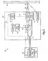
- FIG. 1illustrates a block diagram of a coating removal device according to an embodiment of the present invention.
- the coating removal device 10is an integrated device that includes a laser source 12, a beam splitter 14, scanning optics 16, illuminators 18, a photosensitive detector 20, a comparator 22, a control logic circuit 24, and a waste collector 26.
- the solid lines between elementsrepresent optical paths and the dashed lines represent data signal paths.
- the laser source 12generates a laser pulse, represented as light 30.
- Light 30passes through the beam splitter 14 to the scanning optics 16.
- the light 30is aligned and focused such that the light 30 impinges a specific position 52 on a coated surface 50.
- a laser scanning pathis defined as the path the laser pulse traverses to reach the coated surface 50.
- the laser scanning pathincludes the path through the beam splitter 14 and the scanning optics 16.
- a surface area of the position 52 onto which the light 30 impingescan be made as small or as large as necessary to perform the desired functionality of ablating the coating at the position 52.
- Increasing or decreasing the impinging surface arearespectively decreases or increases the light intensity delivered onto the surface area.
- the amount of light intensityis an adjustable parameter which is used to meet various application specifications. It is understood that the light intensity delivered over a given surface area depends not only on the given surface area but also in part to the laser source specifications and loss within the integrated apparatus.
- the light 30Upon impinging the position 52, the light 30 ablates a portion of the coating corresponding to the position 52. It is anticipated that each laser pulse removes a uniform amount of coating. The amount of coating removed includes the surface area impinged by the light 30 and a depth of the coating at the position 52. An anticipated depth can be calculated based on the intensity of the light 30, the surface area impinged, the nature of the coating, etc. In operation, the actual depth of the coating that is removed can vary from the calculated depth. Underneath the coating to be removed is either a different coating (an undercoating) comprising a different material or a different color, or the original surface material to which the coating was originally applied.
- the undercoating or original surfacereflects a wavelength of light different than that reflected by the coating being removed.
- the illuminators 18provide a light illumination 32 to the position 52 on the coated surface 50.
- Light illumination 32is reflected off the position 52 as reflected light 34 and through the scanning optics 16 to the beam splitter 14.
- the reflected light 34is split, or re-directed, from the laser scanning path as re-directed reflected light 36.
- the light 36is directed to the photosensitive detector 20 where characteristics of the reflected light are measured. Data corresponding to the measured characteristics is sent from the photosensitive detector 20 to the comparator 22 via a data line 40.
- a color sensing pathis defined as the path the reflected light traverses from the coated surface 50 to the photosensitive sensor 20.
- the color sensing pathincludes the path through the scanning optics 16 and the beam splitter 14.
- the color sensing pathincludes the optics that comprises the laser scanning path.
- the comparator 22compares the measured characteristics of the reflected light to previously defined parameters and thresholds.
- the previously defined parameters and thresholdscan be internally stored within the comparator 22, or they can be received from a separate memory for the purposes of being used in the comparison operation.
- the memoryis preferably a conventional memory type located within the integrated device 10. Included within the previously defined parameters are characteristics of the coating to be removed, for example the coating color.
- the results of the comparison made by the comparator 22are sent to the control logic circuit 24 via a data line 42.
- the comparisondetermines if the coating is sufficiently removed from the position 52.
- the wavelength of the reflected lightis measured.
- the reflected light wavelengthindicates a color of a top layer of the coated surface 50 at the position 52 after the portion of coating has been ablated by the impinging light 30. If this measured top layer color is substantially the same as a color of the coating to be removed, as defined by the stored coating parameters, then it is determined that a portion of the coating to be removed still remains at the position 52.
- the laser pulseis then fired at this position and the system then moves to the next position. This process is repeated for an area until a predetermined percentage of the positions within the area do not require the laser to fire. In this case, the system then moves to the next area.
- the control logic circuit 24sends a control signal to the scanning optics 16 via a data line 44, the control signal instructs the scanning optics 16 to realign such that a subsequent laser pulse is directed to a position on the coated surface 50 different than the position 52. After the scanning optics 16 are realigned to a subsequent position, a determination is then made as to whether or not the laser pulse should be fired at the new position.
- a delay in the color sensing circuitcauses an offset between the color sensing location, such as position 52, and the subsequent firing location. If this error is too large, performance maybe inadequate.
- a solution to this problemis to offset the position of the color sensing relative to the stripping position, to provide a look ahead function. Considerations are made for situations where the scanning direction or speed is changed. In these situations, the color sensor is moved to change the offset or multiple sensors are used for different scan speeds and directions.
- individual optical elements within the scanning optics 16are aligned using any conventional means for physically moving one or more of the individual optical elements.
- drive gearsare connected to the optical elements and a motor is connected to the drive gears.
- control signals sent by the control logic circuit 24provide instructions as to the movement of the drive gears using the motor.
- the waste collector 26collects the waste byproduct resulting from the laser pulse impinging the coated surface 50 and ablating the top layer coating.
- the waste collector 26includes a local storage for storing the collected ablated waste byproduct.
- An alternative waste collectoracts as a waste removal apparatus and is coupled to an external waste receptacle such that the collected waste byproduct is transported to the external waste receptacle, as shown in Figure 2 . Operation of the waste collector is described in more detail below.
- FIG. 2illustrates a coating removal device 100 according to another embodiment of the present invention.
- the coating removal device 100includes a head component 110 and a body component 120.
- the body component 120includes a laser source 122 and a waste receptacle 124.
- a fiber optic cable 116, a waste transport tube 114, and a data line 118couple the body component 120 to the head component 110.
- the fiber optic cable 116, the waste transport tube 114, and the data line 118are all preferably bundled together as a single link.
- the body component 120also preferably provides power to the head component 110 via a power line (not shown).
- the power lineis also preferably included within the bundled link between the body component 120 and the head component 110.
- the head component 110includes a power source (not shown) that is independent of the power source of the body component 120.
- the head component 110includes the beam splitter 14, the scanning optics 16, the illuminators 18, the photosensitive detector 20, the comparator 22, and the control logic circuit 24 which operate the same as described above in relation to Figure 1 .
- the fiber optic cable 116provides the light 30 (laser pulse) from the laser source 122.
- the control logic circuit 24provides control signals to the laser source 122 via the data line 118, in a manner similar to that described above in which the control logic circuit 24 provides control signals to the laser source 12 ( Figure 1 ) via data line 46 ( Figure 1 ).
- Illuminationas provided by the illuminators 18, and detection of the resulting reflected light, as performed by the photosensitive detector 20, can be accomplished in several different manners.
- the illuminatorscan be comprised of one to many individual illuminators that provide illumination from a single wavelength to a wide range of wavelengths.
- the photosensitive detector 20can comprise one to many sensors for detecting light.
- One method using a single sensor with a wide spectrum illuminatorconstitutes a grayscale sensor that measures the relative lightness of a surface.
- Another methoduses a spectrophotometer sensor that measures a reflectance at hundreds of different wavelengths.
- two color illumination and sensingis implemented where the two colors are red and blue.
- the preferred configuration of the illuminators 18includes two red illuminators and two blue illuminators. Alternatively, more or less red and blue illuminators can be used. It is contemplated that any illumination and sensing techniques can be used that enables the coating removal system to determine the color of a top layer of a coated surface.
- the illumination colorscan be separated using any conventional technique.
- One approachuses filters within the photosensitive detector such that the filters separate the colors and send each separated color to a corresponding sensor.
- Another approachis to separate the colors using a grating.
- color separationis performed using a single sensor within the photosensitive detector 20 and separating the colors temporally. To accomplish this, the red illuminators are energized and the corresponding reflected light is measured by the sensor in the photosensitive detector 20. Then, the blue illuminators are energized and the corresponding reflected light is measured by the same sensor. The order can be reversed such that the blue light is measured prior to the red light.
- the head component 110also includes a waste collector 112, which is coupled to the waste transport tube 114.
- the waste collector 112collects the waste byproduct resulting from a laser pulse impinging the coated surface 50.
- the collected waste byproductis transported through the waste transport tube 114 to the waste receptacle 124.
- the waste collector 112 and the waste collector 26are preferably of the type described in the co-owned, co-pending U.S. Patent Application Serial No.10/272,329 , filed on October, 15, 2002, and entitled "Laser Scanning Head with Rotary Scanning Coaxial Refractive Optics," which is hereby incorporated by reference.
- impact of the focused laser beam on the target surfaceejects ablation products in a direction generally counter to the direction of the incident beam.
- This waste byproductenters the head component 110 at an exit aperture of a nosepiece (not shown) and preferably mixes internally with a purge-gas stream.
- the nosepieceis preferably shaped internally to redirect the purge stream after it picks up the waste byproducts.
- the exiting waste streamis directed rearward in the nosepiece to a passageway within the housing.
- the passagewaydelivers the purge flow to the waste transport tube 114 for transport to the waste receptacle 124 in the body component 120.
- a vacuum blower(not shown) in the body component 120 draws the purge flow through the service hose.
- a converging nozzle internal to the nosepieceis mounted facing adjacent to the exit aperture.
- the exhaust streamdraws a protective high-speed airflow through the nozzle toward the exit aperture to prevent the gases and particles from the target spot from reaching and contaminating the scanner optics and drive gears used to move the scanning optics.
- the purge gasis preferably supplied through a tubular inlet on the side housing of the head component 110.
- a hose connected to a remote equipment unitsupplies non-combustible gases, or, if allowed in the work area, the inlet is open to ambient air.
- Imaging optics 16Numerous different optical configurations can be used within the scanning optics 16 ( Figures 1 and 2 ) to direct the light 30 to the coated surface 50 and to direct the reflected light 34 from the coated surface 50 the beam splitter 14.
- One such configurationincludes the use of focusing optics and reflecting scanners, for example mirrors.
- Another configurationas shown in Figure 4 , utilizes focusing optics and refracting scanners, such as prisms.
- the scanning optics 16have the ability to be optically configured in any number of different configurations, using any number of optical elements, such that the scanning optics 16 direct a laser light pulse from a first optical position (such as the beam splitter 14) to the coated surface and direct a reflected light from the coated surface back to the first optical position.
- Figure 3illustrates a coating removal system including a first configuration of the scanning optics.
- the scanning optics 16( Figures 1 and 2 ) include focusing optics 202 and 208, and reflecting scanners 204 and 206.
- the first configuration of the scanning optics 16is shown in Figure 3 as being applied to the coating removal system 100 ( Figure 2 ).
- the first configurationcan be equally applied to the coating removal system 10 ( Figure 1 ). For simplicity, not all elements of the coating removal system 100 are shown in Figure 3 .
- the focusing optics 202collimate the light 30 and direct the collimated light to the reflecting scanner 204.
- the light 30is reflected by the reflecting scanners 204 and 206 to the focusing optics 208.
- the focusing optics 208direct and focus the light 30 to a position, such as position 52, on the coated surface 50.
- the exact position on the coated surface 50, and the dimensions of the light impinging the coated surface 50,are determined by the alignments of the focusing optics 202, the reflecting scanners 204 and 206, and the scanning optics 208, which are controlled by control signals sent by the control logic circuit 24.
- the focusing optics 202 and 208are shown in Figure 3 as single elements, it should be clear to those skilled in the art that either or both of the focusing optics 202 and 208 can comprise one or more optical elements.
- two reflecting scanners 204 and 206are shown in Figure 3 , it should be clear that more, or less than two reflecting scanners can be used.
- Figure 3also illustrates a first configuration of the illuminators 18.
- the light illuminators 18include two red illuminators 212 and two blue illuminators 214.
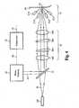
- Figure 4illustrates a coating removal system including a second configuration of the scanning optics.
- the coating removal system shown in Figure 4is the same as the coating removal system of Figure 3 except that the focusing optics 202, reflecting scanners 204 and 206, and focusing optics 208 of Figure 3 are replaced by focusing optics 302, refracting scanners 304 and 306, and focusing optics 308.
- the focusing optics 302collimate the light 30 and direct the collimated light to the refracting scanner 304.
- the light 30is refracted by the refracting scanners 304 and 306 to the focusing optics 308.
- the focusing optics 308direct and focus the light 30 to a position, such as position 52, on the coated surface 50.
- the exact position on the coated surface 50, and the dimensions of the light impinging the coated surface 50,are determined by the alignments of the focusing optics 302, the refracting scanners 304 and 306, and the scanning optics 308, which are controlled by control signals sent by the control logic circuit 24. Preferred operation of the focusing optics 302 and 308, and the refracting optics 304 and 306 is described in the previously referenced U.S. Patent Application Serial No. 10/272,329 .
- the focusing optics 302 and 308are shown in Figure 4 as single elements, it should be clear to those skilled in the art that either or both of the focusing optics 302 and 308 can comprise one or more optical elements.
- two refracting scanners 304 and 306are shown in Figure 4 , it should be clear that more, or less, than two reflecting scanners can be used.
- Figure 5illustrates an alternative configuration of a coating removal device 300.
- the beam splitter 14, the photosensitive detector 20, the comparator 22, and the control logic circuit 24are located in a body component 320 (instead of in the head component as in the head component 110 of coating removal device 100 of Figure 2 ).
- the coating removal device 300operates in a similar manner as the coating removal device 100 ( Figure 2 ) except that reflected light 34 is directed to the body component for detection and analysis.
- the control logic circuit 24, located in the body component 320 of Figure 5sends control signals to the scanning optics 16 in the head component 310 via data line 330.
- Focusing optics 322are included in the body component 320 to focus the light 30 into a first end of the fiber optic cable 116. The focusing optics 322 also direct the reflected light 34 received from the fiber optic cable 116 to the beam splitter 14.
- the coating removal device 10( Figure 1 ) can be adapted such that the laser source 12 and the beam splitter 14 are optically coupled to the scanning optics 16 via a fiber optic cable.
- the photosensitive detector 20can be positioned at the laser source end of the fiber optic cable.
- a coating removal devicedirects a laser pulse to a predetermined position on a coated surface.
- the laser pulseis directed to the predetermined position according to a laser path which includes a beam splitter, focusing optics, and scanning optics.
- the laser pulseupon impinging the predetermined position, ablates some or all of the coating at the predetermined position.
- light illuminatorsprovide light illumination to the predetermined position. Reflected light resulting from the light illumination is directed along a color sensing path to a photosensitive detector.
- the color sensing pathpreferably includes some or all of the optical components of the laser path.
- the beam splitterre-directs the reflected light from the laser path to the photosensitive detector where measurements are taken. These measurements are sent from the photosensitive detector to a comparator where an analysis is made that compares characteristics of the detected light to predefined parameters and thresholds.
- a color of the reflected lightis measured and compared to a known color of the coating that is to be removed. If the comparator determines that the detected light is of the same color as the known color, then it is concluded that coating still remains at the predetermined position on the coated surface. In this case, the laser pulse is fired at the predetermined position. If the comparator determines that the detected light is not the same color as the known color, then it is concluded that coating no longer remains at the predetermined position on the coated surface, and as such, the laser pulse does not need to be fired at the position. In either case, the control logic circuit instructs the focusing and scanning optics to realign to a next position on the coated surface.
- Coating that is ablated by an impinging laser pulseis collected as waste byproduct by a waste removal mechanism.
- the waste removal mechanismis preferably integrated within a common head assembly that includes the laser and color sensing optical paths.
- each laser pulse generated by the laser sourceis directed to a predetermined position on the coated surface.
- the control logic circuitinstructs the focusing and scanning optics to align themselves such that a subsequent laser pulse is directed to a second position different than the first position.
- the coatingis removed from the entire coated surface. That is, if the coated surface comprises a 10 feet by 10 feet surface area, then the coated surface is removed over the entire 100 square feet. In this case, it is most efficient to remove coating from progressively adjacent positions. In other words, where the second position is located adjacent to the first position. However, this is not always the case. In some applications, it is not desired that the entire surface area is to be removed of coating. Instead, only portions of the surface area are to have the coating removed.
- the exact pattern of the coating to be removedcan be any desired pattern.
- the control logic circuitpreferably orchestrates the desired pattern according to a stored algorithm or program.
- Figure 6illustrates an exemplary coating removal pattern.
- the larger boxrepresents a coated surface with a surface area of 7 units by 7 units.
- the shadowed boxeswhich are the odd numbered boxes, represent those positions on the coated surface at which the coating is to be removed.
- the clear boxeswhich are the even numbered boxes, represent those positions on the coated surface at which the coating is not to be removed. If the coating removal system starts removing coating at the box 1, then after the coating is removed, the next position to which the focusing and scanning optics will align is one of the odd numbered boxes. In most circumstances, the next position would be either box 3, 9, or 15, although the exact sequence, as well as the starting position can vary. In this manner, the coated surface can be "roughed up", where only certain positions on the coated surface have the coating removed.
- Figures 1-5each show illumination provided directly at the coated surface 50 by the illuminators 18. It is also contemplated within the present invention that the illuminators can be positioned such that the illumination provided by the illuminators 18 is directed through the scanning optics 16. It is also contemplated that the illumination provided through the scanning optics 16 can be detecting by a photosensitive detector collecting reflected light directly from the coated surface 50.
- the scanning optics 16are described according to the first configuration including focusing optics and reflecting scanners, and according to the second configuration including focusing optics and refracting scanners, it is also contemplated that the scanning optics 16 can comprise any combination of focusing optics, reflecting scanners, and refracting scanners. It is also contemplated that although Figures 3 and 4 each show two different sets of focusing optics, 202/208 and 302/308, each of the two sets can be replaced by a single set of focusing optics.
- sensing of the reflected lightcan be facilitated by providing a color sensing path that is different from the laser path.
- an alternative coating removal deviceis configured in which separate optical paths are configured, one for the laser path and one for the color sensing path.
- any number of optical elementssuch as lens and/or mirrors, can be used to direct the re-directed reflected light from the beam splitter to the photosensitive detector.
Landscapes
- Engineering & Computer Science (AREA)
- Physics & Mathematics (AREA)
- Optics & Photonics (AREA)
- Plasma & Fusion (AREA)
- Mechanical Engineering (AREA)
- Mechanical Optical Scanning Systems (AREA)
- Laser Beam Processing (AREA)
- Investigating Materials By The Use Of Optical Means Adapted For Particular Applications (AREA)
Description
- The invention relates to ablating a coating using a laser. In particular, the invention relates to removing a laser-based coating removal system and to a method of removing a coating from a surface according to the preamble of claims 1 and 27 (see, for example,
US 6 285 002 ). - Delivery of certain wavelengths of radiant energy is facilitated by transmission along flexible silica fibers. The energy is dispersed from the emitting end of an optical fiber in a widening cone. The energy intensity is generally symmetric about the central fiber axis (e.g., uniformly distributed in azimuth) at the emitting end. The distribution of emitted energy orthogonal to the azimuth angle is highly non-uniform, with highest intensity at the central axis, rapidly decreasing with increasing divergence angle relative to the central fiber axis, sometimes approximated by a power cosine function of the divergence angle.
- Energy beam guiding structures are known that use refractive media (e. g. optical lenses) in combination with movable reflective media (e. g. mirrors) to focus and direct diverging radiant energy disposed around the input beam axis to a target of interest The optical lenses typically convert (collimate) the dispersing radiant energy to a second beam with the radiant energy directed more parallel to the input beam axis. The second beam's energy is distributed over a cross-sectional area defined on a target surface oriented in a transverse plane intersecting the optical axis of the second beam. The size of the defined area Is typically limited by the diameter of the lenses. The movable reflective media are coupled to transporting mechanisms and are positioned to modify the direction of the collimated beam as a function of time, typically in a raster pattern scan mode. The dynamic positioning of the reflective media is generally arranged so that the energy of the second beam, averaged over a multiple number of scan cycles, is distributed as a less intense, more uniform energy intensity distribution over the desired target surface area. In addition, one or more condensing (focusing) lens can be used to focus the collimated beam energy to a fine point at the target's surface. Combinations of mirrors and lenses are used to achieve both effects. The typical objective of these combined reflective and refractive elements is to modify the beams intensity distribution over the width of a limited transverse area and to move the scan area over a target surface to produce a less intense, more uniform, energy intensity distribution over a larger area.
- In previous laser scanning heads, the beam Is typically reflected from two raster scanning mirrors movably mounted in a housing where they are disposed with the first mirror intercepting the input beam, reflecting it to the second mirror, which then reflects the beam toward the target.
- Laser-based coating removal systems use pulses of light from high power lasers to ablate or vaporize the paint or other coating from a surface. Each pulse removes the coating from a small region, typically 0.1 to 100 square mm. The laser is pointed to a different area after each pulse, where the removal process is repeated until the entire surface is cleaned.
- An advantage of lasers for coating removal is that each laser pulse removes a predictable portion of the thickness of the coating, in the small region impacted by the pulse. This opens the possibility of selective stripping where, for example, the topcoat could be removed but not the primer.
- There have been previous designs using color as a selection criterion for selective stripping, such as
U. S. Patent Numbers 5,643, 476 , and6,288, 362 , as well asU. S. . These conventional processes utilize a television camera to observe the field being stripped and a computer to analyze the image. The drawback of this approach is the difficulty in maintaining the correspondence between the TV field of view and that of the laser scanner. Any curvature or movement of the surface causes a mismatch between the camera and laser scanning coordinates. This results in a failure to strip desired locations as well as stripping undesired locations.Patent Application Number 10/272,329 US 6,285,002 discloses a non-mechanical scanning means which employs acoustooptical deflectors for scanning. Two acousto-optical deflectors are used to scan the ultra short laser pulse in the X-axis and the Y-axis. The scanning beam passes through a scan lens for focusing the beam on a target surface which is positioned on a X-axis or Y-axis for coarse or rough movement. It is further disclosed that a camera is installed in the optical layout to monitor the machining operation of the work surface.US 5,864,114 describes an apparatus and method whereby the firing of a laser beam is controlled by a control device comprising a setting device to which coordinate data at each position on the structure surface and laser-firing specifications are entered. The removal progress Is monitored by a monitoring device. Specifically, the monitoring device comprises an illumination device for illuminating the surface of the structure, an image pick-up device for picking up the image of the surface of the structure, and a processing device for processing image signals from the image pick-up device to monitor the progress of a target- The present invention are directed to a coating removal apparatus for and a method of removing a coating from a surface as defined in
claims 1 and 27. Laser scanning optics preferably also function as the sensing path for a color sensor to achieve a known correspondence between the scanning optics conditions and the local surface color parameters. - The positions of focusing and scanning optics determine a laser light path to a target location on the coated surface. Immediately prior to firing the laser light pulse onto the target position, illumination is provided to the target position on the surface by one or more illuminators. The illumination is reflected and collected by the scanning and focusing optics. The reflected light is separated from the laser path at some location and sent to a photosensitive detector. A beam splitter is preferably used to re-direct the reflected light from the laser path to the photosensitive detector. The detected illumination signal is then compared with the specifications and this signal is used to determine whether to fire the laser at this particular target location.
- There are several variations possible for implementing this design. In one configuration, the scanning optics include mirrors, also known as reflecting scanners. In another configuration, the scanning optics include refracting scanners where the light is deflected by transmissive optics. Other variations are directed to the illumination that provides the reflected light. Preferably, the illumination is provided at the surface. Alternatively, the illumination is provided through the focusing and scanning optics. It is also possible to provide the illumination through the focusing and scanning optics and have the detector collecting the light directly from the surface.
- Preferably, the laser source is coupled to the focusing optics. Alternatively, the laser source is coupled to the focusing and scanning optics via a fiber optic cable. In this alternative configuration, the photosensitive detector and beam splitter, as well as the illuminator, are located at the laser end of the fiber optic cable.
- The illumination and detection process can be accomplished in several manners. It can vary from the simplicity of a single sensor and illumination at either a single or wide range of wavelengths. In such a configuration, the single detector with a wide spectrum illuminator constitutes a grayscale sensor measuring only the relative lightness of the surface. At the more complex end of the scale, a spectrophotometer sensor measures the reflectance at hundreds of different wavelengths. In the preferred embodiment, two colors, red and blue, are used for measurement.
- The colors can be separated in various ways. One approach uses filters to separate the colors, where each separated color is sent to a corresponding detector. Another technique is to separate the colors using a grating. In the preferred embodiment, a single detector is used and the colors are separated temporally. Using this preferred approach, the red illuminator is energized and the red measurement made, then the blue illuminator is energized and the blue measurement made through the same detector. Alternatively, the blue illuminator is energized and the blue measurement made, then the red illuminator is energized and the red measurement made.
Figure 1 illustrates a block diagram of a coating removal device according to an embodiment of the present invention.Figure 2 illustrates a block diagram of a coating removal device according to another embodiment of the present invention.Figure 3 illustrates a coating removal system including a first configuration of the scanning optics.Figure 4 illustrates a coating removal system including a second configuration of the scanning optics.Figure 5 illustrates a block diagram of a coating removal device according to yet another embodiment of the present invention.Figure 6 illustrates an exemplary coating removal pattern.- Within the figures, similar elements maintain the same reference numerals.
- Embodiments of the present invention are directed to an apparatus for and a method of utilizing a common optics path to provide laser pulses to a coated surface and to direct a light illumination reflected from the coated surface to a photosensitive detector and analyzer. Preferably, the apparatus is an integrated device including a laser source, a beam splitter, scanning optics, a waste removal apparatus, one or more light illuminators, a photosensitive detector, a comparator, and a control logic circuit. Alternatively, the laser source is external to the integrated device and a fiber optic cable is used to connect the laser source to the integrated device.
- The focusing and scanning optics are positioned such that a laser light path is directed to a first position on the coated surface. Immediately prior to firing a laser light pulse on the first position of the coated surface, illuminators provide illumination which is preferably directed to the first position of the coated surface. The illumination is reflected and collected by the focusing and scanning optics and is separated from the laser path at some location by the beam splitter. The separated reflected light is directed to the photosensitive detector. The comparator compares the reflected light detected by the photosensitive detector to predefined specifications in order to determine whether or not to fire the laser at the first position on the coated surface.
- The control logic circuit provides control signals to the laser source to generate each laser pulse. The control logic circuit also provides control signals to the scanning optics such that the scanning optics are properly aligned to direct the laser pulse to a determined position on the coated surface. After the laser pulse impinges the coated surface, the control logic circuit sends control signals to the scanning optics to realign themselves such that a subsequent laser pulse is directed to a second position on the coated surface. After the scanning optics are realigned, the control logic circuit sends a control signal to the laser source to generate the subsequent laser pulse, which is directed to the second position on the coated surface. Procession over the coated surface continues according to a predetermined coating removal pattern. At each position within the pattern, reflected light is collected and analyzed. At each position, preferably a comparator determines if a sufficient amount of coating has not yet been removed. If it is determined that a sufficient amount of coating has not yet been removed, then a laser pulse is preferably fired at that position and then a determination is made of the next position. If it is determined that a sufficient amount of coating has been removed from the position, then the laser pulse is not fired and a determination is made for the next position. This process is repeated for an area until a predetermined percentage of the positions within the area do not require the laser to fire. In this case, the system then moves to the next area. Alternatively, a determination memory is utilized such that if the comparator determines that a sufficient amount of coating has not yet been removed from a position on the coated surface, then the control logic circuit adds the position to a records list such that during a subsequent cycle performed according to the coating removal pattern, a laser pulse is preferably fired only at the positions listed in the records list.
- Ablation of the coating causes a waste byproduct. The waste removal apparatus preferably collects the waste byproduct from the ablated surface and directs the collected waste to an externally coupled waste receptacle. Alternatively, the waste removal apparatus includes local storage for the collected waste byproduct.
Figure 1 illustrates a block diagram of a coating removal device according to an embodiment of the present invention. Thecoating removal device 10 is an integrated device that includes alaser source 12, abeam splitter 14, scanningoptics 16,illuminators 18, aphotosensitive detector 20, acomparator 22, acontrol logic circuit 24, and awaste collector 26. WithinFigure 1 , the solid lines between elements represent optical paths and the dashed lines represent data signal paths. Thelaser source 12 generates a laser pulse, represented as light 30.Light 30 passes through thebeam splitter 14 to thescanning optics 16. Within thescanning optics 16, the light 30 is aligned and focused such that the light 30 impinges aspecific position 52 on acoated surface 50. A laser scanning path is defined as the path the laser pulse traverses to reach thecoated surface 50. In reference toFigure 1 , the laser scanning path includes the path through thebeam splitter 14 and thescanning optics 16.- As is well known in the art of laser optics, a surface area of the
position 52 onto which the light 30 impinges can be made as small or as large as necessary to perform the desired functionality of ablating the coating at theposition 52. Increasing or decreasing the impinging surface area respectively decreases or increases the light intensity delivered onto the surface area. The amount of light intensity is an adjustable parameter which is used to meet various application specifications. It is understood that the light intensity delivered over a given surface area depends not only on the given surface area but also in part to the laser source specifications and loss within the integrated apparatus. - Upon impinging the
position 52, the light 30 ablates a portion of the coating corresponding to theposition 52. It is anticipated that each laser pulse removes a uniform amount of coating. The amount of coating removed includes the surface area impinged by the light 30 and a depth of the coating at theposition 52. An anticipated depth can be calculated based on the intensity of the light 30, the surface area impinged, the nature of the coating, etc. In operation, the actual depth of the coating that is removed can vary from the calculated depth. Underneath the coating to be removed is either a different coating (an undercoating) comprising a different material or a different color, or the original surface material to which the coating was originally applied. In either case, it is anticipated that the undercoating or original surface reflects a wavelength of light different than that reflected by the coating being removed. As such, it can be determined if the coating to be removed is in fact completely removed by measuring a wavelength of light reflected off theposition 52. Theilluminators 18 provide alight illumination 32 to theposition 52 on thecoated surface 50.Light illumination 32 is reflected off theposition 52 as reflected light 34 and through thescanning optics 16 to thebeam splitter 14. At thebeam splitter 14, the reflectedlight 34 is split, or re-directed, from the laser scanning path as re-directed reflectedlight 36. The light 36 is directed to thephotosensitive detector 20 where characteristics of the reflected light are measured. Data corresponding to the measured characteristics is sent from thephotosensitive detector 20 to thecomparator 22 via adata line 40. - A color sensing path is defined as the path the reflected light traverses from the
coated surface 50 to thephotosensitive sensor 20. In reference toFigure 1 , the color sensing path includes the path through thescanning optics 16 and thebeam splitter 14. Within the preferred embodiment, the color sensing path includes the optics that comprises the laser scanning path. - The
comparator 22 compares the measured characteristics of the reflected light to previously defined parameters and thresholds. The previously defined parameters and thresholds can be internally stored within thecomparator 22, or they can be received from a separate memory for the purposes of being used in the comparison operation. The memory is preferably a conventional memory type located within theintegrated device 10. Included within the previously defined parameters are characteristics of the coating to be removed, for example the coating color. - The results of the comparison made by the
comparator 22 are sent to thecontrol logic circuit 24 via adata line 42. The comparison determines if the coating is sufficiently removed from theposition 52. To make this determination, the wavelength of the reflected light is measured. The reflected light wavelength indicates a color of a top layer of thecoated surface 50 at theposition 52 after the portion of coating has been ablated by the impinginglight 30. If this measured top layer color is substantially the same as a color of the coating to be removed, as defined by the stored coating parameters, then it is determined that a portion of the coating to be removed still remains at theposition 52. In this case, the laser pulse is then fired at this position and the system then moves to the next position. This process is repeated for an area until a predetermined percentage of the positions within the area do not require the laser to fire. In this case, the system then moves to the next area. - If the comparison performed by the
comparator 22 determines that the top layer color is substantially different than the previously defined coating color, then it is concluded that directing another laser pulse onto theposition 52 is not necessary. After the laser pulse impinges theposition 52, or it is determined that firing the laser pulse at the position is not necessary, thecontrol logic circuit 24 sends a control signal to thescanning optics 16 via adata line 44, the control signal instructs thescanning optics 16 to realign such that a subsequent laser pulse is directed to a position on thecoated surface 50 different than theposition 52. After thescanning optics 16 are realigned to a subsequent position, a determination is then made as to whether or not the laser pulse should be fired at the new position. - In one embodiment, as the
scanning optics 16 are realigned, a delay in the color sensing circuit causes an offset between the color sensing location, such asposition 52, and the subsequent firing location. If this error is too large, performance maybe inadequate. A solution to this problem is to offset the position of the color sensing relative to the stripping position, to provide a look ahead function. Considerations are made for situations where the scanning direction or speed is changed. In these situations, the color sensor is moved to change the offset or multiple sensors are used for different scan speeds and directions. - Although not shown in the figures, individual optical elements within the
scanning optics 16 are aligned using any conventional means for physically moving one or more of the individual optical elements. For example, drive gears are connected to the optical elements and a motor is connected to the drive gears. In this example, control signals sent by thecontrol logic circuit 24 provide instructions as to the movement of the drive gears using the motor. - The
waste collector 26 collects the waste byproduct resulting from the laser pulse impinging thecoated surface 50 and ablating the top layer coating. Thewaste collector 26 includes a local storage for storing the collected ablated waste byproduct. An alternative waste collector acts as a waste removal apparatus and is coupled to an external waste receptacle such that the collected waste byproduct is transported to the external waste receptacle, as shown inFigure 2 . Operation of the waste collector is described in more detail below. Figure 2 illustrates acoating removal device 100 according to another embodiment of the present invention. Thecoating removal device 100 includes ahead component 110 and abody component 120. Thebody component 120 includes alaser source 122 and awaste receptacle 124. Afiber optic cable 116, awaste transport tube 114, and adata line 118 couple thebody component 120 to thehead component 110. Thefiber optic cable 116, thewaste transport tube 114, and thedata line 118 are all preferably bundled together as a single link. Thebody component 120 also preferably provides power to thehead component 110 via a power line (not shown). The power line is also preferably included within the bundled link between thebody component 120 and thehead component 110. Alternatively, thehead component 110 includes a power source (not shown) that is independent of the power source of thebody component 120.- The
head component 110 includes thebeam splitter 14, thescanning optics 16, theilluminators 18, thephotosensitive detector 20, thecomparator 22, and thecontrol logic circuit 24 which operate the same as described above in relation toFigure 1 . Thefiber optic cable 116 provides the light 30 (laser pulse) from thelaser source 122. Thecontrol logic circuit 24 provides control signals to thelaser source 122 via thedata line 118, in a manner similar to that described above in which thecontrol logic circuit 24 provides control signals to the laser source 12 (Figure 1 ) via data line 46 (Figure 1 ). - Illumination, as provided by the
illuminators 18, and detection of the resulting reflected light, as performed by thephotosensitive detector 20, can be accomplished in several different manners. The illuminators can be comprised of one to many individual illuminators that provide illumination from a single wavelength to a wide range of wavelengths. Similarly, thephotosensitive detector 20 can comprise one to many sensors for detecting light. One method using a single sensor with a wide spectrum illuminator, constitutes a grayscale sensor that measures the relative lightness of a surface. Another method uses a spectrophotometer sensor that measures a reflectance at hundreds of different wavelengths. In the preferred embodiment, two color illumination and sensing is implemented where the two colors are red and blue. The preferred configuration of theilluminators 18 includes two red illuminators and two blue illuminators. Alternatively, more or less red and blue illuminators can be used. It is contemplated that any illumination and sensing techniques can be used that enables the coating removal system to determine the color of a top layer of a coated surface. - The illumination colors can be separated using any conventional technique. One approach uses filters within the photosensitive detector such that the filters separate the colors and send each separated color to a corresponding sensor. Another approach is to separate the colors using a grating. In the preferred embodiment, color separation is performed using a single sensor within the
photosensitive detector 20 and separating the colors temporally. To accomplish this, the red illuminators are energized and the corresponding reflected light is measured by the sensor in thephotosensitive detector 20. Then, the blue illuminators are energized and the corresponding reflected light is measured by the same sensor. The order can be reversed such that the blue light is measured prior to the red light. - Referring again to
Figure 2 , thehead component 110 also includes awaste collector 112, which is coupled to thewaste transport tube 114. Thewaste collector 112 collects the waste byproduct resulting from a laser pulse impinging thecoated surface 50. The collected waste byproduct is transported through thewaste transport tube 114 to thewaste receptacle 124. Thewaste collector 112 and the waste collector 26 (Figure 1 ) are preferably of the type described in the co-owned, co-pendingU.S. Patent Application Serial No.10/272,329 , filed on October, 15, 2002, and entitled "Laser Scanning Head with Rotary Scanning Coaxial Refractive Optics," which is hereby incorporated by reference. - In the preferred embodiment, impact of the focused laser beam on the target surface ejects ablation products in a direction generally counter to the direction of the incident beam. This waste byproduct enters the
head component 110 at an exit aperture of a nosepiece (not shown) and preferably mixes internally with a purge-gas stream. The nosepiece is preferably shaped internally to redirect the purge stream after it picks up the waste byproducts. The exiting waste stream is directed rearward in the nosepiece to a passageway within the housing. The passageway delivers the purge flow to thewaste transport tube 114 for transport to thewaste receptacle 124 in thebody component 120. A vacuum blower (not shown) in thebody component 120 draws the purge flow through the service hose. - A converging nozzle internal to the nosepiece is mounted facing adjacent to the exit aperture. The exhaust stream draws a protective high-speed airflow through the nozzle toward the exit aperture to prevent the gases and particles from the target spot from reaching and contaminating the scanner optics and drive gears used to move the scanning optics.
- The purge gas is preferably supplied through a tubular inlet on the side housing of the
head component 110. A hose connected to a remote equipment unit supplies non-combustible gases, or, if allowed in the work area, the inlet is open to ambient air. - A more detailed description of the
preferred waste collector U.S. Patent Application Serial No. 10/272,329 . - Numerous different optical configurations can be used within the scanning optics 16 (
Figures 1 and2 ) to direct the light 30 to thecoated surface 50 and to direct the reflected light 34 from thecoated surface 50 thebeam splitter 14. One such configuration, as shown inFigure 3 , includes the use of focusing optics and reflecting scanners, for example mirrors. Another configuration, as shown inFigure 4 , utilizes focusing optics and refracting scanners, such as prisms. It is understood that thescanning optics 16 have the ability to be optically configured in any number of different configurations, using any number of optical elements, such that thescanning optics 16 direct a laser light pulse from a first optical position (such as the beam splitter 14) to the coated surface and direct a reflected light from the coated surface back to the first optical position. Figure 3 illustrates a coating removal system including a first configuration of the scanning optics. The scanning optics 16 (Figures 1 and2 ) include focusingoptics scanners scanning optics 16 is shown inFigure 3 as being applied to the coating removal system 100 (Figure 2 ). The first configuration can be equally applied to the coating removal system 10 (Figure 1 ). For simplicity, not all elements of thecoating removal system 100 are shown inFigure 3 .- The focusing
optics 202 collimate the light 30 and direct the collimated light to the reflectingscanner 204. The light 30 is reflected by the reflectingscanners optics 208. The focusingoptics 208 direct and focus the light 30 to a position, such asposition 52, on thecoated surface 50. The exact position on thecoated surface 50, and the dimensions of the light impinging thecoated surface 50, are determined by the alignments of the focusingoptics 202, the reflectingscanners scanning optics 208, which are controlled by control signals sent by thecontrol logic circuit 24. Although the focusingoptics Figure 3 as single elements, it should be clear to those skilled in the art that either or both of the focusingoptics scanners Figure 3 , it should be clear that more, or less than two reflecting scanners can be used. Figure 3 also illustrates a first configuration of theilluminators 18. In this first configuration, thelight illuminators 18 include twored illuminators 212 and twoblue illuminators 214.Figure 4 illustrates a coating removal system including a second configuration of the scanning optics. The coating removal system shown inFigure 4 is the same as the coating removal system ofFigure 3 except that the focusingoptics 202, reflectingscanners optics 208 ofFigure 3 are replaced by focusingoptics 302, refractingscanners optics 308. The focusingoptics 302 collimate the light 30 and direct the collimated light to the refractingscanner 304. The light 30 is refracted by the refractingscanners optics 308. The focusingoptics 308 direct and focus the light 30 to a position, such asposition 52, on thecoated surface 50. The exact position on thecoated surface 50, and the dimensions of the light impinging thecoated surface 50, are determined by the alignments of the focusingoptics 302, the refractingscanners scanning optics 308, which are controlled by control signals sent by thecontrol logic circuit 24. Preferred operation of the focusingoptics optics U.S. Patent Application Serial No. 10/272,329 . Although the focusingoptics Figure 4 as single elements, it should be clear to those skilled in the art that either or both of the focusingoptics scanners Figure 4 , it should be clear that more, or less, than two reflecting scanners can be used.Figure 5 illustrates an alternative configuration of acoating removal device 300. In this alternative configuration, thebeam splitter 14, thephotosensitive detector 20, thecomparator 22, and thecontrol logic circuit 24 are located in a body component 320 (instead of in the head component as in thehead component 110 ofcoating removal device 100 ofFigure 2 ). Thecoating removal device 300 operates in a similar manner as the coating removal device 100 (Figure 2 ) except that reflected light 34 is directed to the body component for detection and analysis. Thecontrol logic circuit 24, located in thebody component 320 ofFigure 5 , sends control signals to thescanning optics 16 in thehead component 310 viadata line 330. Focusingoptics 322 are included in thebody component 320 to focus the light 30 into a first end of thefiber optic cable 116. The focusingoptics 322 also direct the reflected light 34 received from thefiber optic cable 116 to thebeam splitter 14.- In a manner similar to that of
coating removal device 300, it is contemplated that the coating removal device 10 (Figure 1 ) can be adapted such that thelaser source 12 and thebeam splitter 14 are optically coupled to thescanning optics 16 via a fiber optic cable. In such a configuration, thephotosensitive detector 20 can be positioned at the laser source end of the fiber optic cable. - In operation, a coating removal device directs a laser pulse to a predetermined position on a coated surface. The laser pulse is directed to the predetermined position according to a laser path which includes a beam splitter, focusing optics, and scanning optics. The laser pulse, upon impinging the predetermined position, ablates some or all of the coating at the predetermined position. To determine if a proper amount of coating is removed from the predetermined position, light illuminators provide light illumination to the predetermined position. Reflected light resulting from the light illumination is directed along a color sensing path to a photosensitive detector. The color sensing path preferably includes some or all of the optical components of the laser path. The beam splitter re-directs the reflected light from the laser path to the photosensitive detector where measurements are taken. These measurements are sent from the photosensitive detector to a comparator where an analysis is made that compares characteristics of the detected light to predefined parameters and thresholds.
- In the preferred embodiment, a color of the reflected light is measured and compared to a known color of the coating that is to be removed. If the comparator determines that the detected light is of the same color as the known color, then it is concluded that coating still remains at the predetermined position on the coated surface. In this case, the laser pulse is fired at the predetermined position. If the comparator determines that the detected light is not the same color as the known color, then it is concluded that coating no longer remains at the predetermined position on the coated surface, and as such, the laser pulse does not need to be fired at the position. In either case, the control logic circuit instructs the focusing and scanning optics to realign to a next position on the coated surface.
- Coating that is ablated by an impinging laser pulse is collected as waste byproduct by a waste removal mechanism. The waste removal mechanism is preferably integrated within a common head assembly that includes the laser and color sensing optical paths.
- As described in detail above, each laser pulse generated by the laser source is directed to a predetermined position on the coated surface. After the coating is removed from a first position, the control logic circuit instructs the focusing and scanning optics to align themselves such that a subsequent laser pulse is directed to a second position different than the first position. In most applications, the coating is removed from the entire coated surface. That is, if the coated surface comprises a 10 feet by 10 feet surface area, then the coated surface is removed over the entire 100 square feet. In this case, it is most efficient to remove coating from progressively adjacent positions. In other words, where the second position is located adjacent to the first position. However, this is not always the case. In some applications, it is not desired that the entire surface area is to be removed of coating. Instead, only portions of the surface area are to have the coating removed. The exact pattern of the coating to be removed can be any desired pattern. The control logic circuit preferably orchestrates the desired pattern according to a stored algorithm or program.
Figure 6 illustrates an exemplary coating removal pattern. The larger box represents a coated surface with a surface area of 7 units by 7 units. The shadowed boxes, which are the odd numbered boxes, represent those positions on the coated surface at which the coating is to be removed. The clear boxes, which are the even numbered boxes, represent those positions on the coated surface at which the coating is not to be removed. If the coating removal system starts removing coating at the box 1, then after the coating is removed, the next position to which the focusing and scanning optics will align is one of the odd numbered boxes. In most circumstances, the next position would be eitherbox 3, 9, or 15, although the exact sequence, as well as the starting position can vary. In this manner, the coated surface can be "roughed up", where only certain positions on the coated surface have the coating removed.Figures 1-5 each show illumination provided directly at thecoated surface 50 by theilluminators 18. It is also contemplated within the present invention that the illuminators can be positioned such that the illumination provided by theilluminators 18 is directed through thescanning optics 16. It is also contemplated that the illumination provided through thescanning optics 16 can be detecting by a photosensitive detector collecting reflected light directly from thecoated surface 50.- Although the
scanning optics 16 are described according to the first configuration including focusing optics and reflecting scanners, and according to the second configuration including focusing optics and refracting scanners, it is also contemplated that thescanning optics 16 can comprise any combination of focusing optics, reflecting scanners, and refracting scanners. It is also contemplated that althoughFigures 3 and4 each show two different sets of focusing optics, 202/208 and 302/308, each of the two sets can be replaced by a single set of focusing optics. - In certain circumstances, sensing of the reflected light can be facilitated by providing a color sensing path that is different from the laser path. In this case, an alternative coating removal device is configured in which separate optical paths are configured, one for the laser path and one for the color sensing path.
- Although not shown in
Figures 1-5 , any number of optical elements, such as lens and/or mirrors, can be used to direct the re-directed reflected light from the beam splitter to the photosensitive detector. - The present invention has been described in terms of specific embodiments incorporating details to facilitate the understanding of the principles of construction and operation of the invention. Such reference herein to specific embodiments and details thereof is not intended to limit the scope of the claims appended hereto. It will be apparent to those skilled in the art that modifications may be made in the embodiment chosen for illustration without departing from the scope of the invention.
Claims (37)
- A laser-based coating removal system to remove a coating from a surface (50), the system comprising:a. a laser source (12) to provide a laser pulse;b. scanning optics (16) to direct the laser pulse along a laser path to a current position on the surface (50), whereby the laser pulse impinges the current position on the surface thereby ablating a portion of the coating from the current position andcharacterized byc. one or more light illuminators (18) to provide a light illumination along a light illumination path, the light illumination impinging the current position on the surface (50);d. a photosensitive detector (20) to receive light reflected from the surface (50) as a result of the impinging light illumination and to measure the reflected light; ande. a color sensing path to direct the reflected light from the surface (50) to the photosensitive detector (20), wherein the color sensing path includes the scanning optics (16) and the entire color sensing path from the surface (50) to the photosensitive detector (20) is separated from an entire light illumination path from the one or more light illuminators (18) to the surface (50).
- The system of claim 1 further comprising a control logic circuit coupled to the laser source, the scanning optics, and to the photosensitive detector, wherein the control logic circuit provides control signals to the laser source and the scanning optics.
- The system of claim 2 further comprising a comparator coupled to the photosensitive detector to compare the measured reflected light with predetermined parameters to determine if the coating is removed from the current position on the surface.
- The system of claim 3 wherein the control logic circuit provides a first control signal to the scanning optics to direct the laser pulse to the current position on the surface if it is determined that the coating is not removed from the current position.
- The system of claim 4 wherein the current position and each successive position on the surface is determined according to a coating removal pattern.
- The system of claim 5 wherein if it is determined that the coating is not removed from the current position, or each successive position, then the control logic circuit maintains a record list of each position at which the coating is not removed such that an additional laser pulse is directed to each position listed in the record list.
- The system of claim 1 wherein the scanning optics include one or more reflecting scanners.
- The system of claim 7 wherein the one or more reflecting scanners comprise a lens and mirror array.
- The system of claim 1 wherein the scanning optics include one or more refracting scanners.
- The system of claim 9 wherein the one or more refracting scanners comprise a lens and prism array.
- The system of claim 1 wherein the scanning optics include focusing optics.
- The system of claim 1 further comprising a beam splitter to direct the reflected light away from the laser path and toward the photosensitive detector.
- The system of claim 1 wherein the one or more light illuminators provide the light illumination directly to the surface.
- The system of claim 1 wherein the one or more light illuminators provide the light illumination to the surface via the scanning optics.
- The system of claim 1 further comprising an optical fiber coupled between the laser source and the scanning optics to provide the laser pulse from the laser source to the scanning optics.
- The system of claim 1 wherein the one or more light illuminators comprises a single wide spectrum illuminator.
- The system of claim 16 wherein the photosensitive detector comprises a single sensor to measure a relative lightness of the surface.
- The system of claim 16 wherein the photosensitive detector comprises a spectrophotometer sensor to measure the reflectance at a plurality of different wavelengths.
- The system of claim 1 wherein the one or more light illuminators comprises a red spectrum illuminator to provide a red light illumination and a blue spectrum illuminator to provide a blue light illumination.
- The system of claim 19 wherein the photosensitive detector temporally separates a reflected red light resulting from the impinging red spectrum illumination and a reflected blue light resulting from the impinging blue spectrum illumination.
- The system of claim 1 further comprising a waste collection mechanism to collect an ablated portion of the surface.
- An integrated device to remove a coating from a surface (50), comprising a laser-based coating removal system according to claim 1.
- The integrated device of claim 22 further comprising a control logic circuit coupled to the laser source, the scanning optics, and to the photosensitive detector, wherein the control logic circuit provides control signals to the laser source and the scanning optics.
- The integrated device of claim 22 wherein the scanning optics include one or more reflecting scanners.
- The integrated device of claim 22 wherein the scanning optics include one or more refracting scanners.
- A method of removing a coating from a surface (50), the method comprising:a. providing a laser pulse;b. directing the laser pulse along a laser path to a current position on the surface (50), whereby the laser pulse impinges the current position on the surface thereby ablating a portion of the coating from the current position; andcharacterized by the following steps:c. providing a light illumination along a light illumination path by one or more light illuminators (18) that impinges the current position on the surface (50);d. directing a reflected light along a color sensing path, the reflected light resulting from the light illumination impinging the surface (50), wherein the color sensing path includes at least a portion of the laser path;e. receiving the reflecting light at a photosensitive detector (20) wherein the color sensing path includes scanning optics and the entire color sensing path from the surface (50) to the photosensitive detector is separated from an entire light illumination path from the one or more light illuminators to the surface (50); andf. analyzing the received reflected light.
- The method of claim 26 further comprising comparing the analyzed reflected light with predetermined parameters to determine if the coating is removed from the current position on the surface.
- The method of claim 27 further comprising providing and directing a subsequent laser pulse to a next position on the surface.
- The method of claim 27 further comprising determining the current position, the next position, and each successive position on the surface according to a coating removal pattern.
- The method of claim 29 wherein if it is determined that the coating is not removed from the current position, then the method further comprises maintaining a record list of each position at which the coating is not removed, performing a subsequent coating removal cycle according to the coating removal pattern, and during the subsequent coating removal cycle providing and directing an additional laser pulse to each position listed on the record list.
- The method of claim 26 wherein directing the laser pulse along the current laser path includes reflecting the laser pulse.
- The method of claim 26 wherein directing the laser pulse along the current laser path includes refracting the laser pulse.
- The method of claim 26 wherein the light illumination is provided directly to the surface.
- The method of claim 26 wherein the light illumination is directed to the surface via at least a portion of the laser path.
- The method of claim 26 wherein providing the light illumination directed at the current position on the surface comprises providing a plurality of temporally distinct light illuminations
- The method of claim 35 wherein analyzing the received reflected light comprises temporally separating the reflected light.
- The method of claim 26 further comprising collecting the ablated portion of the surface.
Applications Claiming Priority (3)
| Application Number | Priority Date | Filing Date | Title |
|---|---|---|---|
| US53572504P | 2004-01-09 | 2004-01-09 | |
| US11/030,710US7633033B2 (en) | 2004-01-09 | 2005-01-05 | Color sensing for laser decoating |
| PCT/US2005/000511WO2005070093A2 (en) | 2004-01-09 | 2005-01-06 | Color sensing for laser decoating |
Publications (3)
| Publication Number | Publication Date |
|---|---|
| EP1701816A2 EP1701816A2 (en) | 2006-09-20 |
| EP1701816A4 EP1701816A4 (en) | 2008-12-10 |
| EP1701816B1true EP1701816B1 (en) | 2014-12-24 |
Family
ID=34742456
Family Applications (1)
| Application Number | Title | Priority Date | Filing Date |
|---|---|---|---|
| EP05705268.0AExpired - LifetimeEP1701816B1 (en) | 2004-01-09 | 2005-01-06 | Laser based coating removal system and method of removing a coating from a surface |
Country Status (5)
| Country | Link |
|---|---|
| US (5) | US7633033B2 (en) |
| EP (1) | EP1701816B1 (en) |
| JP (1) | JP4970050B2 (en) |
| CA (1) | CA2551647C (en) |
| WO (1) | WO2005070093A2 (en) |
Families Citing this family (83)
| Publication number | Priority date | Publication date | Assignee | Title |
|---|---|---|---|---|
| US7633033B2 (en) | 2004-01-09 | 2009-12-15 | General Lasertronics Corporation | Color sensing for laser decoating |
| US7800014B2 (en)* | 2004-01-09 | 2010-09-21 | General Lasertronics Corporation | Color sensing for laser decoating |
| EP1598121A3 (en)* | 2004-05-18 | 2007-02-14 | Airbus Deutschland GmbH | Laser-based stripping method |
| US20070012665A1 (en)* | 2005-07-12 | 2007-01-18 | Hewlett-Packard Development Company Lp | Laser ablation |
| WO2007028057A2 (en) | 2005-09-02 | 2007-03-08 | General Lasertronics Corporation | Color sensing for laser decoating |
| WO2007118939A1 (en)* | 2006-04-19 | 2007-10-25 | Arcelor France | Method of producing a welded part having very high mechanical properties from a rolled and coated sheet |
| US8536483B2 (en)* | 2007-03-22 | 2013-09-17 | General Lasertronics Corporation | Methods for stripping and modifying surfaces with laser-induced ablation |
| US8381690B2 (en) | 2007-12-17 | 2013-02-26 | International Paper Company | Controlling cooling flow in a sootblower based on lance tube temperature |
| US8585956B1 (en) | 2009-10-23 | 2013-11-19 | Therma-Tru, Inc. | Systems and methods for laser marking work pieces |
| DE102009050784B4 (en)* | 2009-10-27 | 2012-02-16 | Lessmüller Lasertechnik GmbH | Method for image-based control of machining processes and method for repairing defects on workpieces |
| US10112257B1 (en) | 2010-07-09 | 2018-10-30 | General Lasertronics Corporation | Coating ablating apparatus with coating removal detection |
| WO2012058406A1 (en)* | 2010-10-27 | 2012-05-03 | Qunzhou Bian | Ion mobility spectrometer clear-down |
| JP5459255B2 (en)* | 2011-04-08 | 2014-04-02 | 株式会社安川電機 | Robot system |
| WO2013059779A1 (en)* | 2011-10-21 | 2013-04-25 | American Laser Enterprises, Llc | System configured for removing a coating from a substrate using electromagnetic radiation |
| CN103170746A (en)* | 2011-12-26 | 2013-06-26 | 富泰华工业(深圳)有限公司 | Coating removing device and coating removing method thereof |
| CN102554473B (en)* | 2012-01-12 | 2016-01-20 | 深圳市木森科技有限公司 | A kind of method and apparatus of removing solder balls by laser |
| US9895771B2 (en) | 2012-02-28 | 2018-02-20 | General Lasertronics Corporation | Laser ablation for the environmentally beneficial removal of surface coatings |
| WO2013133415A1 (en) | 2012-03-09 | 2013-09-12 | 株式会社トヨコー | Laser irradiation device, laser irradiation system, and method for removing coating or adhering matter |
| WO2014079478A1 (en) | 2012-11-20 | 2014-05-30 | Light In Light Srl | High speed laser processing of transparent materials |
| US9381548B2 (en) | 2013-01-02 | 2016-07-05 | The Boeing Company | Systems for removing lubricants from superplastic-forming or hot-forming dies |
| US9272312B1 (en) | 2013-01-02 | 2016-03-01 | The Boeing Company | Methods and systems for removing lubricants from superplastic-forming or hot-forming dies |
| EP2754524B1 (en) | 2013-01-15 | 2015-11-25 | Corning Laser Technologies GmbH | Method of and apparatus for laser based processing of flat substrates being wafer or glass element using a laser beam line |
| EP2781296B1 (en) | 2013-03-21 | 2020-10-21 | Corning Laser Technologies GmbH | Device and method for cutting out contours from flat substrates using a laser |
| JP6270820B2 (en)* | 2013-03-27 | 2018-01-31 | 国立大学法人九州大学 | Laser annealing equipment |
| US10293436B2 (en) | 2013-12-17 | 2019-05-21 | Corning Incorporated | Method for rapid laser drilling of holes in glass and products made therefrom |
| US9676167B2 (en) | 2013-12-17 | 2017-06-13 | Corning Incorporated | Laser processing of sapphire substrate and related applications |
| US11556039B2 (en) | 2013-12-17 | 2023-01-17 | Corning Incorporated | Electrochromic coated glass articles and methods for laser processing the same |
| US9850160B2 (en) | 2013-12-17 | 2017-12-26 | Corning Incorporated | Laser cutting of display glass compositions |
| US9701563B2 (en) | 2013-12-17 | 2017-07-11 | Corning Incorporated | Laser cut composite glass article and method of cutting |
| US9815730B2 (en) | 2013-12-17 | 2017-11-14 | Corning Incorporated | Processing 3D shaped transparent brittle substrate |
| US20150165560A1 (en) | 2013-12-17 | 2015-06-18 | Corning Incorporated | Laser processing of slots and holes |
| US10442719B2 (en) | 2013-12-17 | 2019-10-15 | Corning Incorporated | Edge chamfering methods |
| US10086597B2 (en) | 2014-01-21 | 2018-10-02 | General Lasertronics Corporation | Laser film debonding method |
| US9541282B2 (en) | 2014-03-10 | 2017-01-10 | International Paper Company | Boiler system controlling fuel to a furnace based on temperature of a structure in a superheater section |
| CN106687419A (en) | 2014-07-08 | 2017-05-17 | 康宁股份有限公司 | Methods and apparatuses for laser processing materials |
| JP6788571B2 (en) | 2014-07-14 | 2020-11-25 | コーニング インコーポレイテッド | Interface blocks, systems and methods for cutting transparent substrates within a wavelength range using such interface blocks. |
| EP3169479B1 (en) | 2014-07-14 | 2019-10-02 | Corning Incorporated | Method of and system for arresting incident crack propagation in a transparent material |
| CN208586209U (en) | 2014-07-14 | 2019-03-08 | 康宁股份有限公司 | A system for forming contoured multiple defects in a workpiece |
| KR20170028943A (en)* | 2014-07-14 | 2017-03-14 | 코닝 인코포레이티드 | System for and method of processing transparent materials using laser beam focal lines adjustable in length and diameter |
| US10060688B2 (en) | 2014-07-25 | 2018-08-28 | Integrated Test & Measurement (ITM) | System and methods for detecting, monitoring, and removing deposits on boiler heat exchanger surfaces using vibrational analysis |
| US9927231B2 (en)* | 2014-07-25 | 2018-03-27 | Integrated Test & Measurement (ITM), LLC | System and methods for detecting, monitoring, and removing deposits on boiler heat exchanger surfaces using vibrational analysis |
| BR112017001511B1 (en) | 2014-07-25 | 2021-03-02 | International Paper Company | methods, system and computer program product to detect fouling of a boiler heat exchanger |
| CN105406028A (en)* | 2014-09-12 | 2016-03-16 | 东莞新能源科技有限公司 | Polar piece coating removing method |
| WO2016037352A1 (en)* | 2014-09-12 | 2016-03-17 | 东莞新能源科技有限公司 | Electrode plate coating removal method |
| US10047001B2 (en) | 2014-12-04 | 2018-08-14 | Corning Incorporated | Glass cutting systems and methods using non-diffracting laser beams |
| CN107406293A (en) | 2015-01-12 | 2017-11-28 | 康宁股份有限公司 | The substrate through heat tempering is cut by laser using Multiphoton Absorbtion method |
| US20160223775A1 (en)* | 2015-01-30 | 2016-08-04 | Corning Optical Communications LLC | Fiber stripping methods and apparatus |
| HUE055461T2 (en) | 2015-03-24 | 2021-11-29 | Corning Inc | Laser cutting and processing of display glass compositions |
| JP2018516215A (en) | 2015-03-27 | 2018-06-21 | コーニング インコーポレイテッド | Gas permeable window and manufacturing method thereof |
| US10018782B2 (en) | 2015-05-28 | 2018-07-10 | Corning Optical Communications LLC | Optical fiber stripping methods and apparatus |
| JP7082042B2 (en) | 2015-07-10 | 2022-06-07 | コーニング インコーポレイテッド | A method for continuously forming holes in a flexible substrate sheet and related products. |
| EP3359324B1 (en) | 2015-10-07 | 2021-11-17 | Corning Incorporated | Method of laser cutting a coated substrate |
| EP3402619B1 (en)* | 2016-01-14 | 2020-12-23 | Howmet Aerospace Inc. | Methods for producing forged products and other worked products |
| SG11201809797PA (en) | 2016-05-06 | 2018-12-28 | Corning Inc | Laser cutting and removal of contoured shapes from transparent substrates |
| CN105750743A (en)* | 2016-05-20 | 2016-07-13 | 上海市激光技术研究所 | Laser welding device and method based on laser cleaning pretreatment |
| US10410883B2 (en) | 2016-06-01 | 2019-09-10 | Corning Incorporated | Articles and methods of forming vias in substrates |
| US10794679B2 (en) | 2016-06-29 | 2020-10-06 | Corning Incorporated | Method and system for measuring geometric parameters of through holes |
| JP6348149B2 (en)* | 2016-07-08 | 2018-06-27 | ファナック株式会社 | Laser processing robot system that performs laser processing using a robot |
| KR20190035805A (en) | 2016-07-29 | 2019-04-03 | 코닝 인코포레이티드 | Apparatus and method for laser processing |
| EP3507057A1 (en) | 2016-08-30 | 2019-07-10 | Corning Incorporated | Laser processing of transparent materials |
| US10730783B2 (en) | 2016-09-30 | 2020-08-04 | Corning Incorporated | Apparatuses and methods for laser processing transparent workpieces using non-axisymmetric beam spots |
| EP3529214B1 (en) | 2016-10-24 | 2020-12-23 | Corning Incorporated | Substrate processing station for laser-based machining of sheet-like glass substrates |
| US10752534B2 (en) | 2016-11-01 | 2020-08-25 | Corning Incorporated | Apparatuses and methods for laser processing laminate workpiece stacks |
| CN110087818B (en)* | 2016-11-23 | 2020-12-29 | 艾普伦 | Method for laser lift-off of moving metal products and device for carrying out said method |
| US10259213B2 (en)* | 2016-12-12 | 2019-04-16 | Paper Converting Machine Company | Apparatus and method for printing roll cleaning |
| JP6464213B2 (en)* | 2017-02-09 | 2019-02-06 | ファナック株式会社 | Laser processing system having laser processing head and imaging device |
| US10688599B2 (en) | 2017-02-09 | 2020-06-23 | Corning Incorporated | Apparatus and methods for laser processing transparent workpieces using phase shifted focal lines |
| CN110366480A (en)* | 2017-02-28 | 2019-10-22 | 惠普发展公司,有限责任合伙企业 | Amount of radiation for expected surface property level determines |
| US10580725B2 (en) | 2017-05-25 | 2020-03-03 | Corning Incorporated | Articles having vias with geometry attributes and methods for fabricating the same |
| US11078112B2 (en) | 2017-05-25 | 2021-08-03 | Corning Incorporated | Silica-containing substrates with vias having an axially variable sidewall taper and methods for forming the same |
| US10626040B2 (en) | 2017-06-15 | 2020-04-21 | Corning Incorporated | Articles capable of individual singulation |
| KR101984647B1 (en)* | 2017-07-06 | 2019-06-03 | 삼성중공업 주식회사 | Laser cleaning device having a function of checking cleaning quality and method thereof |
| WO2019110114A1 (en)* | 2017-12-07 | 2019-06-13 | Bystronic Laser Ag | Device for monitoring beam treatment of a workpiece and use thereof, device for beam treatment of a workpiece and use thereof, method for monitoring beam treatment of a workpiece, method for beam treatment of a workpiece |
| US12180108B2 (en) | 2017-12-19 | 2024-12-31 | Corning Incorporated | Methods for etching vias in glass-based articles employing positive charge organic molecules |
| US11554984B2 (en) | 2018-02-22 | 2023-01-17 | Corning Incorporated | Alkali-free borosilicate glasses with low post-HF etch roughness |
| US11235359B2 (en)* | 2019-02-11 | 2022-02-01 | The Boeing Company | Robotic laser and vacuum cleaning for environmental gains |
| CN109877462A (en)* | 2019-02-28 | 2019-06-14 | 大族激光科技产业集团股份有限公司 | A kind of coat of metal removal system and coat of metal minimizing technology |
| ES2802900B2 (en)* | 2019-07-18 | 2021-06-22 | Univ Vigo | Method for cleaning chewing gum residue or its derivatives |
| US11173526B2 (en)* | 2019-11-27 | 2021-11-16 | Lockheed Martin Corporation | Automated structural laser cleaning system |
| US20210341140A1 (en) | 2020-05-01 | 2021-11-04 | International Paper Company | System and methods for controlling operation of a recovery boiler to reduce fouling |
| DE102020112472A1 (en) | 2020-05-07 | 2021-11-11 | Jenoptik Optical Systems Gmbh | Objective for a material processing device, material processing device and method for operating a material processing device |
| US11577341B2 (en) | 2020-05-11 | 2023-02-14 | The Boeing Company | Quality inspection of laser material processing |
| EP4088855B1 (en)* | 2021-03-30 | 2024-01-31 | The Boeing Company | Laser module end effector for robotic device |
Citations (1)
| Publication number | Priority date | Publication date | Assignee | Title |
|---|---|---|---|---|
| US5281798A (en)* | 1991-12-24 | 1994-01-25 | Maxwell Laboratories, Inc. | Method and system for selective removal of material coating from a substrate using a flashlamp |
Family Cites Families (183)
| Publication number | Priority date | Publication date | Assignee | Title |
|---|---|---|---|---|
| US3657707A (en)* | 1969-03-17 | 1972-04-18 | Precision Instr Co | Laser recording system with both surface defect and data error checking |
| US3626141A (en) | 1970-04-30 | 1971-12-07 | Quantronix Corp | Laser scribing apparatus |
| DE2145921C2 (en)* | 1971-09-14 | 1982-05-06 | Günther Dr. 8022 Grünwald Nath | Device for material processing by means of a laser beam with a flexible light guide |
| US3771880A (en) | 1971-09-29 | 1973-11-13 | Us Navy | Roughness analyzer |
| US3941973A (en)* | 1974-06-26 | 1976-03-02 | Raytheon Company | Laser material removal apparatus |
| US4114018A (en) | 1976-09-30 | 1978-09-12 | Lasag Ag | Method for ablating metal workpieces with laser radiation |
| IT1117550B (en)* | 1977-08-01 | 1986-02-17 | Righini Giancarlo | TRANSPORT AND FOCUS SYSTEM OF LASER RADIATION WITH OPTICAL FIBER PARTICULARLY FOR MEDICAL SURGICAL AND BIOLOGICAL APPLICATIONS |
| US4148057A (en)* | 1977-10-25 | 1979-04-03 | Solution Sciences, Inc. | Direct laser printing and forming apparatus |
| US4136779A (en) | 1977-12-22 | 1979-01-30 | Owens-Illinois, Inc. | Ampule score line detection |
| US4207874A (en) | 1978-03-27 | 1980-06-17 | Choy Daniel S J | Laser tunnelling device |
| US4328068A (en) | 1980-07-22 | 1982-05-04 | Rca Corporation | Method for end point detection in a plasma etching process |
| IT1167852B (en)* | 1981-03-24 | 1987-05-20 | Stefano Sottini | HIGH POWER LASER RADIATION TRANSMISSION DEVICE USING A VARIABLE SECTION OPTICAL FIBER AND ITS REALIZATION PROCEDURE |
| WO1983001400A1 (en) | 1981-10-22 | 1983-04-28 | First Of Chelsea Corp | Laser removal of materials from surfaces |
| US4449043A (en)* | 1981-10-30 | 1984-05-15 | The United States Of America As Represented By The Secretary Of The Air Force | Optical power source control system |
| USRE33777E (en)* | 1982-01-26 | 1991-12-24 | Avco Corporation | Laser removal of poor thermally-conductive materials |
| US4756765A (en)* | 1982-01-26 | 1988-07-12 | Avco Research Laboratory, Inc. | Laser removal of poor thermally-conductive materials |
| JPS58159501U (en)* | 1982-04-19 | 1983-10-24 | 旭光学工業株式会社 | Transmission fiber trouble detection safety device |
| YU44680B (en)* | 1982-07-30 | 1990-12-31 | Glaxo Lab Ltd | Process for obtaining very pure amorphous form of cephuroxim axetile |
| JPS5935892A (en)* | 1982-08-20 | 1984-02-27 | Nec Corp | Laser working device |
| US4676586A (en)* | 1982-12-20 | 1987-06-30 | General Electric Company | Apparatus and method for performing laser material processing through a fiber optic |
| DE3319203C2 (en) | 1983-05-27 | 1986-03-27 | Fa. Carl Zeiss, 7920 Heidenheim | Device for dose measurement during photocoagulation |
| DE3336229A1 (en)* | 1983-10-05 | 1985-04-25 | Resista Fabrik elektrischer Widerstände GmbH, 8300 Landshut | METHOD FOR ADJUSTING THE VALUE OF RESISTORS |
| US4588885A (en)* | 1984-02-07 | 1986-05-13 | International Technical Associates | Method of and apparatus for the removal of paint and the like from a substrate |
| US4986664A (en)* | 1984-02-07 | 1991-01-22 | International Technical Associates | System and process for controlled removal of material to produce a desired surface contour |
| US4737628A (en)* | 1984-02-07 | 1988-04-12 | International Technical Associates | Method and system for controlled and selective removal of material |
| US4564736A (en)* | 1984-05-07 | 1986-01-14 | General Electric Company | Industrial hand held laser tool and laser system |
| US4695698A (en)* | 1984-07-10 | 1987-09-22 | Larassay Holding Ag | Method of, and apparatus for, generating a predetermined pattern using laser radiation |
| US4566937A (en)* | 1984-10-10 | 1986-01-28 | The United States Of America As Represented By The United States Department Of Energy | Electron beam enhanced surface modification for making highly resolved structures |
| US4671848A (en)* | 1984-12-17 | 1987-06-09 | General Laser, Inc. | Method for laser-induced removal of a surface coating |
| JPS61161781A (en)* | 1985-01-10 | 1986-07-22 | Canon Inc | Laser adjusting device |
| JPS61188509A (en)* | 1985-02-16 | 1986-08-22 | Nippon Hoso Kyokai <Nhk> | optical coupling device |
| US4729621A (en)* | 1985-03-11 | 1988-03-08 | Shiley Inc. | Integral optical fiber coupler |
| EP0199868A1 (en)* | 1985-05-03 | 1986-11-05 | Hughes Technology Pty Ltd. | Safelaser pointers |
| JPH059688Y2 (en)* | 1985-09-02 | 1993-03-10 | ||
| US4707073A (en)* | 1985-09-04 | 1987-11-17 | Raytheon Company | Fiber optic beam delivery system for high-power laser |
| US4654532A (en)* | 1985-09-09 | 1987-03-31 | Ord, Inc. | Apparatus for improving the numerical aperture at the input of a fiber optics device |
| US4737004A (en)* | 1985-10-03 | 1988-04-12 | American Telephone And Telegraph Company, At&T Bell Laboratories | Expanded end optical fiber and associated coupling arrangements |
| US4749840A (en)* | 1986-05-16 | 1988-06-07 | Image Micro Systems, Inc. | Intense laser irradiation using reflective optics |
| DE3737455A1 (en) | 1986-11-06 | 1988-05-19 | Westinghouse Electric Corp | DEVICE AND METHOD FOR PRODUCING COLOR PATTERNS |
| US4818062A (en)* | 1987-04-28 | 1989-04-04 | Spectra Diode Laboratories, Inc. | Optical system with bright light output |
| US4818049A (en)* | 1987-06-10 | 1989-04-04 | Allied-Signal Inc. | Method and apparatus for efficiently conveying light over a distance and effecting controlled illumination by projection thereof |
| US4842360A (en) | 1987-06-18 | 1989-06-27 | Summit Technology, Inc. | High energy laser-to-waveguide coupling devices and methods |
| FR2617746A1 (en)* | 1987-07-10 | 1989-01-13 | Framatome Sa | WELDING DEVICE WITHIN A SMALL DIAMETER TUBE |
| US4944567A (en)* | 1987-11-05 | 1990-07-31 | Allied-Signal Inc. | Fiber optic laser beam delivery system |
| US4799755A (en)* | 1987-12-21 | 1989-01-24 | General Electric Company | Laser materials processing with a lensless fiber optic output coupler |
| JP2683926B2 (en)* | 1988-01-25 | 1997-12-03 | 三菱電機株式会社 | Insulation-coated wire stripping method and device |
| JPH01203090A (en) | 1988-02-09 | 1989-08-15 | Tomoki Takashima | Device for cleaning pipe |
| US4876444A (en) | 1988-03-07 | 1989-10-24 | Tennant Company | Protection from extraneous light for light guided vehicle |
| US4859075A (en) | 1988-03-14 | 1989-08-22 | Directed Energy, Inc. | Laser thermal testing method and system for use with a fire alarm system |
| US5364390A (en)* | 1988-05-19 | 1994-11-15 | Refractive Laser Research And Development, Inc. | Handpiece and related apparatus for laser surgery and dentistry |
| US4900891A (en) | 1988-06-20 | 1990-02-13 | Roger Vega | Laser ice removal system |
| US4844574A (en) | 1988-07-05 | 1989-07-04 | General Electric Company | Optical fiber output coupler for a power laser |
| US5531857A (en)* | 1988-07-08 | 1996-07-02 | Cauldron Limited Partnership | Removal of surface contaminants by irradiation from a high energy source |
| US4880959A (en) | 1988-10-26 | 1989-11-14 | International Business Machines Corporation | Process for interconnecting thin-film electrical circuits |
| GB2226970B (en) | 1989-01-11 | 1992-10-21 | British Aerospace | Methods of manufacture and surface treatment using laser radiation |
| FR2641718B1 (en)* | 1989-01-17 | 1992-03-20 | Ardt | METHOD FOR CLEANING THE SURFACE OF SOLID MATERIALS AND DEVICE FOR CARRYING OUT THIS METHOD, USING A PULSE PULSE LASER, SHORT PULSES, OF WHICH THE BEAM FOCUSES ON THE SURFACE TO BE CLEANED |
| US4928695A (en) | 1989-02-17 | 1990-05-29 | Leon Goldman | Laser diagnostic and treatment device |
| US4960988A (en)* | 1989-03-06 | 1990-10-02 | Murasa International | Safety shut-off protection system |
| JPH02263854A (en) | 1989-04-05 | 1990-10-26 | C I Kasei Co Ltd | Agricultural vinyl chloride resin coating material |
| US5014207A (en) | 1989-04-21 | 1991-05-07 | E. I. Du Pont De Nemours And Company | Solid imaging system |
| FR2649030B1 (en)* | 1989-06-28 | 1992-04-24 | Framatome Sa | LASER WELDING DEVICE WITHIN A TUBULAR ELEMENT |
| US4920994A (en) | 1989-09-12 | 1990-05-01 | The United States Of America As Represented By The United States Department Of Energy | Laser removal of sludge from steam generators |
| DE69026780T2 (en) | 1989-09-22 | 1996-11-07 | Fuji Photo Film Co Ltd | Scanning microscope and scanning mechanism therefor |
| FR2661371A1 (en) | 1990-04-25 | 1991-10-31 | Aron Rosa Daniele | Method and device for restoring a work of art |
| US5386112A (en)* | 1990-06-29 | 1995-01-31 | Dixon; Arthur E. | Apparatus and method for transmitted-light and reflected-light imaging |
| GB2246099A (en) | 1990-07-18 | 1992-01-22 | Silitek Corp | Marking indicia on keytops |
| US5040479A (en)* | 1990-07-24 | 1991-08-20 | Apollo Plastics Corporation | Illuminated multiple color button and method of manufacturing the same |
| US5068750A (en)* | 1990-10-22 | 1991-11-26 | Hughes Aircraft Company | Contaminant removal from telescope optical elements |
| US5355063A (en)* | 1990-11-01 | 1994-10-11 | Westinghouse Electric Corp. | Robotic system for servicing the heat exchanger tubes of a nuclear steam generator |
| US5216808A (en) | 1990-11-13 | 1993-06-08 | General Electric Company | Method for making or repairing a gas turbine engine component |
| US5210944A (en) | 1990-11-13 | 1993-05-18 | General Electric Company | Method for making a gas turbine engine component |
| US5107445A (en) | 1990-12-04 | 1992-04-21 | Luxtron Corporation | Modular luminescence-based measuring system using fast digital signal processing |
| US5784162A (en) | 1993-08-18 | 1998-07-21 | Applied Spectral Imaging Ltd. | Spectral bio-imaging methods for biological research, medical diagnostics and therapy |
| US5113802A (en)* | 1991-03-26 | 1992-05-19 | Union Camp Corporation | Method and apparatus for removing deposit from recovery boilers |
| JPH0582276A (en) | 1991-09-25 | 1993-04-02 | Matsushita Electric Works Ltd | Discharge lamp lighting device |
| US5229593A (en)* | 1991-10-08 | 1993-07-20 | International Business Machines Corporation | Apparatus and method for safe, free space laser communication |
| FR2683473B1 (en)* | 1991-11-13 | 1994-03-04 | Framatome | LASER WORKING DEVICE WITHIN A TUBULAR ELEMENT. |
| JPH05138377A (en) | 1991-11-18 | 1993-06-01 | Toshiba Corp | Laser processing equipment |
| US5571335A (en) | 1991-12-12 | 1996-11-05 | Cold Jet, Inc. | Method for removal of surface coatings |
| US5610753A (en)* | 1991-12-12 | 1997-03-11 | Eastman Kodak Company | Optical design of laser scanner to reduce thermal sensitivity |
| US5328517A (en)* | 1991-12-24 | 1994-07-12 | Mcdonnell Douglas Corporation | Method and system for removing a coating from a substrate using radiant energy and a particle stream |
| US5194723A (en)* | 1991-12-24 | 1993-03-16 | Maxwell Laboratories, Inc. | Photoacoustic control of a pulsed light material removal process |
| US5613509A (en)* | 1991-12-24 | 1997-03-25 | Maxwell Laboratories, Inc. | Method and apparatus for removing contaminants and coatings from a substrate using pulsed radiant energy and liquid carbon dioxide |
| US5395362A (en)* | 1992-01-14 | 1995-03-07 | Summit Technology | Methods and apparatus for distributing laser radiation |
| CA2091512A1 (en)* | 1992-03-13 | 1993-09-14 | Kohichi Haruta | Laser irradiation nozzle and laser apparatus using the same |
| FR2689423B1 (en) | 1992-04-01 | 1995-09-01 | Valinox | DEVICE AND METHOD FOR LASER BEAM CLEANING OF THE INTERNAL WALL OF TUBES. |
| JPH0694427A (en)* | 1992-07-31 | 1994-04-05 | Hitachi Ltd | Machining groove depth detecting method and device therefor, and ion-milling device and manufacture of electronic/optical element |
| US5291570A (en)* | 1992-09-09 | 1994-03-01 | Hobart Laser Products, Inc. | High power laser - optical fiber connection system |
| US5245682A (en)* | 1992-09-25 | 1993-09-14 | General Electric Company | Fiber optic delivered beam quality control system for power lasers |
| DE4241575A1 (en)* | 1992-12-10 | 1994-06-16 | Baldwin Gegenheimer Gmbh | Printing roller cleaning - uses laser beam to detach dirt and residue from surface without affecting surface character |
| CA2102884A1 (en)* | 1993-03-04 | 1994-09-05 | James J. Wynne | Dental procedures and apparatus using ultraviolet radiation |
| US5373140A (en)* | 1993-03-16 | 1994-12-13 | Vernay Laboratories, Inc. | System for cleaning molding equipment using a laser |
| US5805275A (en)* | 1993-04-08 | 1998-09-08 | Kollmorgen Corporation | Scanning optical rangefinder |
| US5581346A (en)* | 1993-05-10 | 1996-12-03 | Midwest Research Institute | System for characterizing semiconductor materials and photovoltaic device |
| US5333218A (en)* | 1993-05-24 | 1994-07-26 | General Electric Company | Optical fiber tapered output end preparation for improved high power laser/fiber delivered beam quality |
| EP0633541A1 (en) | 1993-07-06 | 1995-01-11 | Opticon Sensors Europe B.V. | Scanning device |
| DE4333501C2 (en) | 1993-10-01 | 1998-04-09 | Univ Stuttgart Strahlwerkzeuge | Method for determining the instantaneous penetration depth of a machining laser beam into a workpiece and device for carrying out this method |
| JP2781718B2 (en)* | 1993-10-19 | 1998-07-30 | ミヤチテクノス株式会社 | YAG laser processing machine |
| US5558666A (en)* | 1994-01-14 | 1996-09-24 | Coherent, Inc. | Handpiece for producing highly collimated laser beam for dermatological procedures |
| JP3159593B2 (en) | 1994-02-28 | 2001-04-23 | 三菱電機株式会社 | Laser processing method and apparatus |
| US5864114A (en)* | 1994-03-10 | 1999-01-26 | Toshiharu Ishikawa | Coating removal apparatus using coordinate-controlled laser beam |
| US5548113A (en)* | 1994-03-24 | 1996-08-20 | Trustees Of Boston University | Co-axial detection and illumination with shear force dithering in a near-field scanning optical microscope |
| US5656186A (en) | 1994-04-08 | 1997-08-12 | The Regents Of The University Of Michigan | Method for controlling configuration of laser induced breakdown and ablation |
| DE4422867A1 (en) | 1994-06-30 | 1996-01-04 | Itt Ind Gmbh Deutsche | Sensor with a programmable switching threshold |
| US5643476A (en)* | 1994-09-21 | 1997-07-01 | University Of Southern California | Laser system for removal of graffiti |
| US5451765A (en)* | 1994-10-31 | 1995-09-19 | Gerber; Peter | Eye safety protection system for a laser transmission system wherein laser energy scattered back along the beam path is detected |
| US5637245A (en)* | 1995-04-13 | 1997-06-10 | Vernay Laboratories, Inc. | Method and apparatus for minimizing degradation of equipment in a laser cleaning technique |
| US5662762A (en)* | 1995-07-07 | 1997-09-02 | Clover Industries, Inc. | Laser-based system and method for stripping coatings from substrates |
| US5780806A (en)* | 1995-07-25 | 1998-07-14 | Lockheed Idaho Technologies Company | Laser ablation system, and method of decontaminating surfaces |
| WO1998006676A1 (en)* | 1996-08-13 | 1998-02-19 | Nippon Sheet Glass Co., Ltd. | LASER MACHINING METHOD FOR GlASS SUBSTRATE, DIFFRACTION TYPE OPTICAL DEVICE FABRICATED BY THE MACHINING METHOD, AND METHOD OF MANUFACTURING OPTICAL DEVICE |
| US5845646A (en)* | 1996-11-05 | 1998-12-08 | Lemelson; Jerome | System and method for treating select tissue in a living being |
| US5986234A (en)* | 1997-03-28 | 1999-11-16 | The Regents Of The University Of California | High removal rate laser-based coating removal system |
| JPH10309516A (en)* | 1997-05-12 | 1998-11-24 | Sumitomo Heavy Ind Ltd | Method for removing coating by laser and laser processor |
| JPH1128900A (en)* | 1997-05-12 | 1999-02-02 | Sumitomo Heavy Ind Ltd | Paint removal method and laser processing device using laser light |
| JPH1126733A (en) | 1997-07-03 | 1999-01-29 | Seiko Epson Corp | Transfer method of thin film device, thin film device, thin film integrated circuit device, active matrix substrate, liquid crystal display device, and electronic equipment |
| US6074382A (en)* | 1997-08-29 | 2000-06-13 | Asah Medico A/S | Apparatus for tissue treatment |
| US6165170A (en)* | 1998-01-29 | 2000-12-26 | International Business Machines Corporation | Laser dermablator and dermablation |
| KR100260766B1 (en) | 1998-02-18 | 2000-08-01 | 구본준 | The equipment for laser annealing |
| US6288362B1 (en)* | 1998-04-24 | 2001-09-11 | James W. Thomas | Method and apparatus for treating surfaces and ablating surface material |
| US6494960B1 (en) | 1998-04-27 | 2002-12-17 | General Electric Company | Method for removing an aluminide coating from a substrate |
| US6437285B1 (en)* | 1998-06-02 | 2002-08-20 | General Lasertronics Corporation | Method and apparatus for treating interior cylindrical surfaces and ablating surface material thereon |
| JP3768029B2 (en)* | 1998-08-31 | 2006-04-19 | Ntn株式会社 | Pattern defect repair device |
| JP2000103607A (en) | 1998-09-30 | 2000-04-11 | Laser Oyo Kogaku Kenkyusho:Kk | Apparatus and method for generating excited nitrogen |
| US6313435B1 (en) | 1998-11-20 | 2001-11-06 | 3M Innovative Properties Company | Mask orbiting for laser ablated feature formation |
| US6285002B1 (en)* | 1999-05-10 | 2001-09-04 | Bryan Kok Ann Ngoi | Three dimensional micro machining with a modulated ultra-short laser pulse |
| JP2001068829A (en)* | 1999-06-21 | 2001-03-16 | Fine Device:Kk | Method and apparatus for cutting short-circuited part of printed wiring board |
| JP3756723B2 (en)* | 1999-07-27 | 2006-03-15 | 松下電工株式会社 | Processing method of printed wiring board |
| US6347976B1 (en) | 1999-11-30 | 2002-02-19 | The Boeing Company | Coating removal system having a solid particle nozzle with a detector for detecting particle flow and associated method |
| JP2001300755A (en) | 2000-04-19 | 2001-10-30 | Hitachi Constr Mach Co Ltd | Method and device for laser beam machining |
| KR100500343B1 (en)* | 2000-08-29 | 2005-07-12 | 미쓰비시덴키 가부시키가이샤 | Laser machining apparatus |
| DE10047113C2 (en) | 2000-09-22 | 2003-06-18 | Pepperl & Fuchs | sensor device |
| ATE291226T1 (en)* | 2001-01-05 | 2005-04-15 | Stiftung A Wegener Inst Polar | ANALYSIS METHOD FOR DETECTING SPATIAL TRACE ELEMENT DISTRIBUTION PATTERNS AND DEVICE FOR IMPLEMENTING THE METHOD |
| US6693255B2 (en) | 2001-03-22 | 2004-02-17 | R. F. Envirotech, Inc. | Laser ablation cleaning |
| JP2002350624A (en) | 2001-05-25 | 2002-12-04 | Canon Inc | Optical element, scanning optical system having the same, and image forming apparatus |
| US6629464B2 (en) | 2001-10-03 | 2003-10-07 | Ui Won Suh | Laser shock peening quality assurance by acoustic analysis |
| US7009141B1 (en)* | 2001-10-13 | 2006-03-07 | General Lasertronics Corp. | Rotary scanning laser head with coaxial refractive optics |
| US6635844B2 (en) | 2002-01-03 | 2003-10-21 | United Microelectronics Corp. | Apparatus for on-line cleaning a wafer chuck with laser |
| DE10210518A1 (en) | 2002-03-09 | 2003-10-02 | Mtu Aero Engines Gmbh | Process for stripping engine components and device for carrying out the process |
| US7408130B2 (en) | 2002-04-01 | 2008-08-05 | Honda Giken Kogyo Kabushiki Kaisha | YAG laser induced arc filler wire composite welding method and weldimg equipment |
| US6864478B2 (en)* | 2002-04-22 | 2005-03-08 | Visx, Incorporation | Beam position monitoring for laser eye surgery |
| US6664499B1 (en)* | 2002-07-11 | 2003-12-16 | The Boeing Company | Tube and duct trim machine |
| DE10243449B4 (en)* | 2002-09-19 | 2014-02-20 | Leica Microsystems Cms Gmbh | CARS microscope and method for CARS microscopy |
| US20050224474A1 (en) | 2002-10-17 | 2005-10-13 | Kilburn Chris A | Method and apparatus for removing a thermal barrier coating from a power generation component |
| AU2003278047A1 (en) | 2002-10-31 | 2004-05-25 | Stephen F. Corbin | System and method for closed-loop control of laser cladding by powder injection |
| US7154066B2 (en)* | 2002-11-06 | 2006-12-26 | Ultratech, Inc. | Laser scanning apparatus and methods for thermal processing |
| US9320792B2 (en) | 2002-11-08 | 2016-04-26 | Ablynx N.V. | Pulmonary administration of immunoglobulin single variable domains and constructs thereof |
| US20040199151A1 (en)* | 2003-04-03 | 2004-10-07 | Ceramoptec Industries, Inc. | Power regulated medical underskin irradiation treament system |
| GB2402230B (en) | 2003-05-30 | 2006-05-03 | Xsil Technology Ltd | Focusing an optical beam to two foci |
| JP4231349B2 (en)* | 2003-07-02 | 2009-02-25 | 株式会社ディスコ | Laser processing method and laser processing apparatus |
| US6964312B2 (en) | 2003-10-07 | 2005-11-15 | International Climbing Machines, Inc. | Surface traversing apparatus and method |
| US7397014B2 (en) | 2003-12-18 | 2008-07-08 | Retainagroup Limited | Portable laser apparatus for marking an object |
| US7800014B2 (en)* | 2004-01-09 | 2010-09-21 | General Lasertronics Corporation | Color sensing for laser decoating |
| US7633033B2 (en) | 2004-01-09 | 2009-12-15 | General Lasertronics Corporation | Color sensing for laser decoating |
| WO2005105306A2 (en) | 2004-04-30 | 2005-11-10 | Basell Polyolefine Gmbh | Process for the reduction and safe disposal of an activated chromium oxide catalyst |
| EP1598121A3 (en)* | 2004-05-18 | 2007-02-14 | Airbus Deutschland GmbH | Laser-based stripping method |
| JP2008502809A (en) | 2004-06-16 | 2008-01-31 | ピーピージー インダストリーズ オハイオ, インコーポレイテッド | Method for removing a polymer coating layer from a coated substrate |
| US20060151433A1 (en) | 2005-01-10 | 2006-07-13 | Chi-Lung Chang | Method for removing and recoating of diamond-like carbon films and its products thereof |
| US20060186098A1 (en) | 2005-02-23 | 2006-08-24 | Caristan Charles L | Method and apparatus for laser processing |
| US7336168B2 (en) | 2005-06-06 | 2008-02-26 | Lawrence Kates | System and method for variable threshold sensor |
| US7867404B2 (en) | 2005-11-15 | 2011-01-11 | Joel Allen Deutsch | Method for converting electrical components |
| WO2007101112A1 (en) | 2006-02-24 | 2007-09-07 | Uvtech Systems, Inc. | Method and apparatus for delivery of pulsed laser radiation |
| ATE518366T1 (en) | 2006-02-28 | 2011-08-15 | Brother Ind Ltd | VIDEO IMAGE DISPLAY DEVICE |
| US8319145B2 (en) | 2006-07-10 | 2012-11-27 | Lazare Kaplan International, Inc. | System and method for gemstone micro-inscription |
| US9089926B2 (en) | 2006-11-04 | 2015-07-28 | Trumpf Werkzeugmaschinen Gmbh + Co. Kg | Process monitoring the processing of a material |
| US8536483B2 (en) | 2007-03-22 | 2013-09-17 | General Lasertronics Corporation | Methods for stripping and modifying surfaces with laser-induced ablation |
| JP5240190B2 (en) | 2007-04-09 | 2013-07-17 | 旭硝子株式会社 | Production method of retardation plate |
| MX2009013616A (en) | 2007-06-12 | 2010-06-01 | Technolines Llc | High speed and high power laser scribing methods and systems. |
| US8182609B1 (en) | 2007-08-09 | 2012-05-22 | Rave, Llc | Apparatus and method for direct surface cleaning |
| US7535565B1 (en) | 2008-01-08 | 2009-05-19 | General Electric Company | System and method for detecting and analyzing compositions |
| JP5293993B2 (en) | 2008-01-09 | 2013-09-18 | ソニー株式会社 | Stereolithography apparatus and stereolithography method |
| US8687189B2 (en) | 2008-03-03 | 2014-04-01 | Ajjer, Llc | Analysis of arrays by laser induced breakdown spectroscopy |
| EP2105782A1 (en) | 2008-03-25 | 2009-09-30 | Wilhelm Anger | Method and device for processing coated spectacles |
| JP4618360B2 (en) | 2008-10-10 | 2011-01-26 | ソニー株式会社 | Laser annealing method and laser annealing apparatus |
| US8729427B2 (en) | 2009-03-27 | 2014-05-20 | Electro Scientific Industries, Inc. | Minimizing thermal effect during material removal using a laser |
| GB0907110D0 (en) | 2009-04-24 | 2009-06-03 | Rolls Royce Plc | Surface sensors |
| MX2011011369A (en) | 2009-04-27 | 2012-01-20 | Echelon Laser Systems Lp | Staggered laser-etch line graphic system, method and articles of manufacture. |
| US20110088720A1 (en) | 2009-10-20 | 2011-04-21 | General Electric Company | Methods for cleaning substrates |
| US9061375B2 (en) | 2009-12-23 | 2015-06-23 | General Electric Company | Methods for treating superalloy articles, and related repair processes |
| US8309880B2 (en) | 2010-01-29 | 2012-11-13 | Phoenix Silicon International Corporation | Coating layer removing apparatus and method for the same |
| GB2481190B (en) | 2010-06-04 | 2015-01-14 | Plastic Logic Ltd | Laser ablation |
| US8604380B2 (en) | 2010-08-19 | 2013-12-10 | Electro Scientific Industries, Inc. | Method and apparatus for optimally laser marking articles |
| US20130036380A1 (en) | 2011-08-02 | 2013-02-07 | Apple Inc. | Graphical User Interface for Tracking and Displaying Views of an Application |
| JP2013159743A (en) | 2012-02-07 | 2013-08-19 | Nitto Denko Corp | Method for peeling pressure-sensitive adhesive agent laminate and pressure-sensitive adhesive agent layer used therein |
- 2005
- 2005-01-05USUS11/030,710patent/US7633033B2/enactiveActive
- 2005-01-06EPEP05705268.0Apatent/EP1701816B1/ennot_activeExpired - Lifetime
- 2005-01-06CACA2551647Apatent/CA2551647C/ennot_activeExpired - Fee Related
- 2005-01-06JPJP2006549436Apatent/JP4970050B2/ennot_activeExpired - Lifetime
- 2005-01-06WOPCT/US2005/000511patent/WO2005070093A2/ennot_activeApplication Discontinuation
- 2009
- 2009-11-06USUS12/614,220patent/US8030594B2/ennot_activeExpired - Lifetime
- 2011
- 2011-08-30USUS13/221,508patent/US8269135B2/ennot_activeExpired - Fee Related
- 2012
- 2012-08-16USUS13/587,828patent/US8610025B2/ennot_activeExpired - Lifetime
- 2013
- 2013-11-12USUS14/078,332patent/US9375807B2/enactiveActive
Patent Citations (1)
| Publication number | Priority date | Publication date | Assignee | Title |
|---|---|---|---|---|
| US5281798A (en)* | 1991-12-24 | 1994-01-25 | Maxwell Laboratories, Inc. | Method and system for selective removal of material coating from a substrate using a flashlamp |
Also Published As
| Publication number | Publication date |
|---|---|
| EP1701816A4 (en) | 2008-12-10 |
| US9375807B2 (en) | 2016-06-28 |
| US20140069897A1 (en) | 2014-03-13 |
| US8269135B2 (en) | 2012-09-18 |
| US20120006806A1 (en) | 2012-01-12 |
| US20120321735A1 (en) | 2012-12-20 |
| CA2551647A1 (en) | 2005-08-04 |
| CA2551647C (en) | 2014-07-08 |
| WO2005070093A3 (en) | 2006-04-20 |
| US8030594B2 (en) | 2011-10-04 |
| JP4970050B2 (en) | 2012-07-04 |
| US7633033B2 (en) | 2009-12-15 |
| JP2007517674A (en) | 2007-07-05 |
| EP1701816A2 (en) | 2006-09-20 |
| US20050150878A1 (en) | 2005-07-14 |
| US8610025B2 (en) | 2013-12-17 |
| WO2005070093A2 (en) | 2005-08-04 |
| US20100044357A1 (en) | 2010-02-25 |
Similar Documents
| Publication | Publication Date | Title |
|---|---|---|
| EP1701816B1 (en) | Laser based coating removal system and method of removing a coating from a surface | |
| US7800014B2 (en) | Color sensing for laser decoating | |
| CN113365773B (en) | Method and apparatus for controlled processing of workpieces | |
| US9375974B2 (en) | Polygonal laser scanner and imaging system for coating removal | |
| US9370842B2 (en) | Methods for stripping and modifying surfaces with laser-induced ablation | |
| US11860091B2 (en) | Apparatus and method for in-situ optical inspection of laser-induced surface modifications and laser process control | |
| CN107835725B (en) | Laser processing apparatus | |
| JP4107833B2 (en) | Laser processing head | |
| CN111670345A (en) | Method and device for detecting the focal position of a laser beam | |
| US20180059407A1 (en) | Optical apparatus, machining apparatus, and article manufacturing method | |
| JP7064606B2 (en) | A device for identifying the focal position of a laser processing system, a laser processing system equipped with the device, and a method for specifying the focal position of the laser processing system. | |
| JP3007875B2 (en) | Laser output detection method and device, and laser output control method and device using the method | |
| EP1919651B1 (en) | Color sensing for laser decoating | |
| US11187838B2 (en) | Spectral filter for high-power fiber illumination sources | |
| CN117733321A (en) | Process monitor for laser processing heads | |
| US20240167948A1 (en) | Apparatus and method for in-situ optical inspection of laser-induced surface modifications and laser process control | |
| JP2002509032A (en) | Workpiece lighting device | |
| GB2627788A (en) | Ablation monitoring | |
| JPH0520194B2 (en) |
Legal Events
| Date | Code | Title | Description |
|---|---|---|---|
| PUAI | Public reference made under article 153(3) epc to a published international application that has entered the european phase | Free format text:ORIGINAL CODE: 0009012 | |
| 17P | Request for examination filed | Effective date:20060706 | |
| AK | Designated contracting states | Kind code of ref document:A2 Designated state(s):AT BE BG CH CY CZ DE DK EE ES FI FR GB GR HU IE IS IT LI LT LU MC NL PL PT RO SE SI SK TR | |
| AX | Request for extension of the european patent | Extension state:AL BA HR LV MK YU | |
| DAX | Request for extension of the european patent (deleted) | ||
| RBV | Designated contracting states (corrected) | Designated state(s):DE FR GB | |
| A4 | Supplementary search report drawn up and despatched | Effective date:20081106 | |
| 17Q | First examination report despatched | Effective date:20090519 | |
| GRAP | Despatch of communication of intention to grant a patent | Free format text:ORIGINAL CODE: EPIDOSNIGR1 | |
| INTG | Intention to grant announced | Effective date:20131004 | |
| GRAP | Despatch of communication of intention to grant a patent | Free format text:ORIGINAL CODE: EPIDOSNIGR1 | |
| INTG | Intention to grant announced | Effective date:20140313 | |
| GRAP | Despatch of communication of intention to grant a patent | Free format text:ORIGINAL CODE: EPIDOSNIGR1 | |
| INTG | Intention to grant announced | Effective date:20140714 | |
| GRAS | Grant fee paid | Free format text:ORIGINAL CODE: EPIDOSNIGR3 | |
| GRAA | (expected) grant | Free format text:ORIGINAL CODE: 0009210 | |
| AK | Designated contracting states | Kind code of ref document:B1 Designated state(s):DE FR GB | |
| REG | Reference to a national code | Ref country code:GB Ref legal event code:FG4D | |
| REG | Reference to a national code | Ref country code:DE Ref legal event code:R096 Ref document number:602005045505 Country of ref document:DE Effective date:20150219 | |
| REG | Reference to a national code | Ref country code:DE Ref legal event code:R097 Ref document number:602005045505 Country of ref document:DE | |
| PLBE | No opposition filed within time limit | Free format text:ORIGINAL CODE: 0009261 | |
| STAA | Information on the status of an ep patent application or granted ep patent | Free format text:STATUS: NO OPPOSITION FILED WITHIN TIME LIMIT | |
| 26N | No opposition filed | Effective date:20150925 | |
| REG | Reference to a national code | Ref country code:FR Ref legal event code:PLFP Year of fee payment:12 | |
| REG | Reference to a national code | Ref country code:FR Ref legal event code:PLFP Year of fee payment:13 | |
| REG | Reference to a national code | Ref country code:FR Ref legal event code:PLFP Year of fee payment:14 | |
| REG | Reference to a national code | Ref country code:DE Ref legal event code:R082 Ref document number:602005045505 Country of ref document:DE Representative=s name:D YOUNG & CO LLP, DE | |
| PGFP | Annual fee paid to national office [announced via postgrant information from national office to epo] | Ref country code:DE Payment date:20240207 Year of fee payment:20 Ref country code:GB Payment date:20240130 Year of fee payment:20 | |
| PGFP | Annual fee paid to national office [announced via postgrant information from national office to epo] | Ref country code:FR Payment date:20240131 Year of fee payment:20 | |
| REG | Reference to a national code | Ref country code:DE Ref legal event code:R071 Ref document number:602005045505 Country of ref document:DE | |
| REG | Reference to a national code | Ref country code:GB Ref legal event code:PE20 Expiry date:20250105 | |
| PG25 | Lapsed in a contracting state [announced via postgrant information from national office to epo] | Ref country code:GB Free format text:LAPSE BECAUSE OF EXPIRATION OF PROTECTION Effective date:20250105 |